US8038611B2 - Surgical methods and surgical kits - Google Patents
Surgical methods and surgical kitsDownload PDFInfo
- Publication number
- US8038611B2 US8038611B2US11/016,549US1654904AUS8038611B2US 8038611 B2US8038611 B2US 8038611B2US 1654904 AUS1654904 AUS 1654904AUS 8038611 B2US8038611 B2US 8038611B2
- Authority
- US
- United States
- Prior art keywords
- retractor
- base component
- blade
- connector arm
- connector
- Prior art date
- Legal status (The legal status is an assumption and is not a legal conclusion. Google has not performed a legal analysis and makes no representation as to the accuracy of the status listed.)
- Expired - Fee Related, expires
Links
Images


Classifications
- A—HUMAN NECESSITIES
- A61—MEDICAL OR VETERINARY SCIENCE; HYGIENE
- A61B—DIAGNOSIS; SURGERY; IDENTIFICATION
- A61B17/00—Surgical instruments, devices or methods
- A61B17/02—Surgical instruments, devices or methods for holding wounds open, e.g. retractors; Tractors
- A61B17/0218—Surgical instruments, devices or methods for holding wounds open, e.g. retractors; Tractors for minimally invasive surgery
- A—HUMAN NECESSITIES
- A61—MEDICAL OR VETERINARY SCIENCE; HYGIENE
- A61B—DIAGNOSIS; SURGERY; IDENTIFICATION
- A61B17/00—Surgical instruments, devices or methods
- A61B17/02—Surgical instruments, devices or methods for holding wounds open, e.g. retractors; Tractors
- A—HUMAN NECESSITIES
- A61—MEDICAL OR VETERINARY SCIENCE; HYGIENE
- A61B—DIAGNOSIS; SURGERY; IDENTIFICATION
- A61B17/00—Surgical instruments, devices or methods
- A61B17/34—Trocars; Puncturing needles
- A61B17/3417—Details of tips or shafts, e.g. grooves, expandable, bendable; Multiple coaxial sliding cannulas, e.g. for dilating
- A61B17/3421—Cannulas
- A61B17/3439—Cannulas with means for changing the inner diameter of the cannula, e.g. expandable
- A—HUMAN NECESSITIES
- A61—MEDICAL OR VETERINARY SCIENCE; HYGIENE
- A61B—DIAGNOSIS; SURGERY; IDENTIFICATION
- A61B17/00—Surgical instruments, devices or methods
- A61B17/02—Surgical instruments, devices or methods for holding wounds open, e.g. retractors; Tractors
- A61B17/0293—Surgical instruments, devices or methods for holding wounds open, e.g. retractors; Tractors with ring member to support retractor elements
- A—HUMAN NECESSITIES
- A61—MEDICAL OR VETERINARY SCIENCE; HYGIENE
- A61B—DIAGNOSIS; SURGERY; IDENTIFICATION
- A61B17/00—Surgical instruments, devices or methods
- A61B17/34—Trocars; Puncturing needles
- A61B17/3462—Trocars; Puncturing needles with means for changing the diameter or the orientation of the entrance port of the cannula, e.g. for use with different-sized instruments, reduction ports, adapter seals
- A—HUMAN NECESSITIES
- A61—MEDICAL OR VETERINARY SCIENCE; HYGIENE
- A61B—DIAGNOSIS; SURGERY; IDENTIFICATION
- A61B17/00—Surgical instruments, devices or methods
- A61B17/00234—Surgical instruments, devices or methods for minimally invasive surgery
- A61B2017/00238—Type of minimally invasive operation
- A61B2017/00261—Discectomy
- A—HUMAN NECESSITIES
- A61—MEDICAL OR VETERINARY SCIENCE; HYGIENE
- A61B—DIAGNOSIS; SURGERY; IDENTIFICATION
- A61B17/00—Surgical instruments, devices or methods
- A61B2017/00367—Details of actuation of instruments, e.g. relations between pushing buttons, or the like, and activation of the tool, working tip, or the like
- A61B2017/00407—Ratchet means
- A—HUMAN NECESSITIES
- A61—MEDICAL OR VETERINARY SCIENCE; HYGIENE
- A61B—DIAGNOSIS; SURGERY; IDENTIFICATION
- A61B17/00—Surgical instruments, devices or methods
- A61B17/02—Surgical instruments, devices or methods for holding wounds open, e.g. retractors; Tractors
- A61B17/025—Joint distractors
- A61B2017/0256—Joint distractors for the spine
- A—HUMAN NECESSITIES
- A61—MEDICAL OR VETERINARY SCIENCE; HYGIENE
- A61B—DIAGNOSIS; SURGERY; IDENTIFICATION
- A61B17/00—Surgical instruments, devices or methods
- A61B17/34—Trocars; Puncturing needles
- A61B17/3417—Details of tips or shafts, e.g. grooves, expandable, bendable; Multiple coaxial sliding cannulas, e.g. for dilating
- A61B17/3421—Cannulas
- A61B2017/3443—Cannulas with means for adjusting the length of a cannula
- A—HUMAN NECESSITIES
- A61—MEDICAL OR VETERINARY SCIENCE; HYGIENE
- A61B—DIAGNOSIS; SURGERY; IDENTIFICATION
- A61B90/00—Instruments, implements or accessories specially adapted for surgery or diagnosis and not covered by any of the groups A61B1/00 - A61B50/00, e.g. for luxation treatment or for protecting wound edges
- A61B90/30—Devices for illuminating a surgical field, the devices having an interrelation with other surgical devices or with a surgical procedure
- A61B2090/306—Devices for illuminating a surgical field, the devices having an interrelation with other surgical devices or with a surgical procedure using optical fibres
Definitions
- retractorsare available to keep an incision open and provide a clear view of the operating field.
- Retractorsare used in surgical operations to reposition muscular tissue, vessels, nerves, and other tissue with the aid of retractor blades, thereby providing access to the site of the operation.
- Surgical retractorsare particularly important in performing surgical procedures that involve the spinal column, where access to the surgical sight can be obtained, for example, through a posterior, posterior-lateral, anterior, lateral, or an anterior-lateral approach.
- a step-wise dilation of the surgical incisioncan be performed to gradually dilate the muscles and tissues to the required size to insert the retractor.
- Step-wise dilationcan involve the use of a series of dilators or cannulae with successively larger diameters. This method involves first inserting the smallest dilator or cannula into an incision. Then a second dilator or cannula, with a slightly larger diameter, is slid over the smaller dilator or cannula and into the incision, thereby causing the incision to expand to the slightly larger diameter of the second dilator or cannula.
- This processcan be repeated using a series of dilators or cannulae with successively larger diameters, until the incision is large enough to allow for insertion of the retractor. Once positioned, the retractors produce a small surgical site or window. However, most currently available retractors are large and cumbersome, requiring a long incision length that traumatizes the patient's muscles and tissue.
- the surgical retractorcomprises a frame and at least two retractor blades attached to the frame.
- the frameincludes a first base component, a second base component, and a connector.
- the connectorconnects the first base component and the second base component, and the first base component and/or the second base component are moveable along a length of the connector.
- the framemoves from a first position to a second position and causes a distance between the first base component and the second base component to change;
- the surgical retractors of the inventioncomprise a first retractor blade, a second retractor blade, a third retractor blade, a fourth retractor blade, a first connector, and a second connector.
- the first connectoris assembled to a proximal end of the first retractor blade and a proximal end of the second retractor blade, and the first retractor blade and/or the second retractor blade is movable along a line that is parallel to a length of the first connector.
- the second connectoris assembled to a proximal end of the third retractor blade and a proximal end of the fourth retractor blade, and the third retractor blade and/or the fourth retractor blade is movable along a line that is parallel to a length of the second connector.
- the first connector and/or the second connectoris movable along a line that intersects the first connector and the second connector.
- this inventionincludes an assembly comprising a surgical retractor (e.g., a surgical retractor of the invention) assembled to an obtruator.
- a surgical retractore.g., a surgical retractor of the invention
- the surgical retractors of the inventioncomprise a housing component having a central axis and a cylindrical expander component.
- the housing componentincludes a cylindrical portion and a blade portion.
- the cylindrincal portiondefines a conduit having an inner diameter normal to the central axis.
- the blade portionis contiguous with one end of the cylindrical portion and includes at least two blades.
- a distal portion of each bladeis moveable relative to the central axis. In a first position, the distal ends of the blade portion are proximate, and upon movement of the distal portion of the blades relative to the central axis, the blades move from a first position to a second position and form a conduit down the length of the central axis.
- the cylindrical expander portionhas an outer diameter that is smaller than the inner diameter of the cylindrical portion and the expander component is movably attached to the housing component.
- this inventionincludes an illuminated surgical cannula comprising a surgical cannula and an interface ring.
- the surgical cannulahas an outer diameter, an inner diameter, a distal end, and a proximal end, wherein an interior area is defined by the inner diameter, the distal end, and the proximal end.
- the interface ringis attached to the proximal end and includes a light source interface in photonic communication with an array of fiber optic wire. The array is arranged to direct light towards the distal end of the cannula.
- this inventionincludes surgical methods.
- the methodscomprise incising tissue of a mammal to create an incision, expanding the incision to create a pathway from the incision to a surgical site, directing a retractor (e.g., a retractor of the invention) into the pathway, creating a working channel through the retractor by separating at least two retractor blades, and performing at least a portion of a surgical procedure through the working channel.
- a retractore.g., a retractor of the invention
- the pathwayextends to a first vertebra and at least a portion of the surgical procedure is performed at the first vertebra
- the methodfurther includes directing an instrument or implant between at least two retractor blades to access a second vertebra adjacent to the first vertebra.
- the retractoris expanded by separating a first retractor blade from a second retractor blade by moving at least one of the first retractor blade and the second retractor blade along an first connector of the retractor and separating a third retractor blade from a fourth retractor blade by moving at least one of the third retractor blade and the fourth retractor blade along a second connector, wherein the second connector is oriented at an angle to the first connector.
- the retractors of this inventioncan be inserted into a body with the ease of a tubular-based system (e.g., a step-wise dilation system), while allowing the surgeon to further retract tissue and muscle once the retractor is located at its fixed position in the body.
- This inventionallows the insertion of a retractor with either step-wise dilation of a minimally invasive incision (e.g., a stab incision), by, for example, inserting the retractor over one or more dilators or without step-wise dilation of the incision by, for example, inserting the retractor through an open incision or through a minimally invasive incision that is expanded by methods other than sequential dilation.
- the inventionprovides methods and devices that reduce the invasiveness and trauma associated with surgical procedures.
- the illuminated cannula of this inventioneliminate the need for light sources that restrict the working space.
- FIG. 1illustrates a view of a portion of one embodiment of a retractor of the invention.
- FIG. 2illustrates a view of a partially disassembled portion of one embodiment of a retractor of the invention.
- FIG. 3illustrates a portion of a first base component of one embodiment of the invention.
- FIG. 4illustrates a ratchet release button of one embodiment of the invention.
- FIG. 5illustrates a second base component of one embodiment of the invention.
- FIGS. 6-8illustrate one embodiment of a retractor of the invention in three different positions or degrees of expansion.
- FIGS. 9-12illustrate four different views of one embodiment of a retractor of the invention.
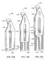
- FIGS. 13A-13Cillustrate the inner face of a blade of one embodiment of the invention with a blade extension at progressively longer telescopic lengths.
- FIG. 14illustrates a close up view of the distal end of the outer face of the blade extension shown in FIGS. 13A-13C .
- FIG. 15illustrates one embodiments of a retractor of the invention that includes blade extensions.
- FIG. 16A-16Millustrates another embodiment of a retractor of the invention.
- FIGS. 17A-17Cillustrate various blade shapes for some embodiments of retractors of the invention.
- FIGS. 17D-17Fillustrate optional blade features for some embodiments of retractors of the invention.
- FIG. 18illustrates one embodiment of a retractor of the invention.
- FIG. 19illustrates one embodiment of a retractor of the invention.
- FIG. 20illustrates one method of attaching additional blades to one embodiment of a retractor of an invention.
- FIGS. 21A-21Dillustrates one embodiment of a retractor of the invention.
- FIGS. 22A-22Hillustrate one embodiment of a method used to retract tissue near the spine of a human.
- FIG. 23illustrates one embodiment of an insertion tube.
- FIG. 24illustrates another embodiment of an insertion tube.
- FIG. 25illustrates one embodiment of an assembly of the invention that includes a retractor positioned over an obtruator and a series of dilators.
- FIG. 26illustrates one embodiment of a distraction instrument.
- FIGS. 27 and 28illustrate one method of expanding one embodiment of a retractor of the invention with one embodiment of a distraction instrument.
- FIGS. 29 and 30illustrates one embodiment of a retractor of the invention.
- FIG. 31illustrates one embodiment of a retractor of the invention with distal ends at a first position and FIG. 32 illustrates the retractor with distal ends at a second position.
- FIG. 33illustrates the retractor shown in FIGS. 31 and 32 with one embodiment of an attached expander component.
- FIG. 34illustrates one embodiment of an interface ring.
- FIG. 35illustrates a portion of one embodiment of a cannula of the invention.
- FIG. 36illustrates the interface ring of FIG. 34 assembled to a portion of the cannula of FIG. 35 .
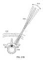
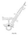
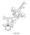
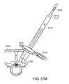
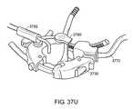
- FIGS. 37A-37Uillustrate embodiments of the invention that include a method of using a retractor (e.g., a retractor of the invention) during a surgical procedure on the spine of a human and related instruments and tools.
- a retractore.g., a retractor of the invention
- This inventionincludes surgical retractors that provide a surgical site.
- the surgical retractorcomprises an expandable frame attached to at least two retractor blades.
- the retractorsinclude an expandable frame.
- the expandable frameincludes two or more base components and at least one connector that connects the base components (e.g., 3, 4, 5, 6, 7, 8, or more than 8 base components and/or connectors). At least two of the base components are connected by one or more connectors (e.g., a ratchet arm or a hinge) that are moveable relative to at least one base component.
- the expandable framemoves from a first position to a second position, thereby causing an average distance between the base components to increase or decrease (i.e., the expandable base expands or contracts).
- Moving the connectors relative to at least one base componentcauses the expandable frame to move from a first position to a second position, thereby causing an average distance between the base components to increase or decrease.
- Moving the same, or another, connector relative to the same, or another, base componentcauses the expandable frame to move from the second position to a third position or back to the first position, thereby causing the average distance between the base components to increase or decrease.
- first positionAs used herein, the terms “first position,” “second position,” and “third position” are used to merely refer to dissimilar positions and are not meant to imply that all embodiments of the expandable frame can only be adjusted to one, two, or three positions.
- the expandable frameis adjustable to a finite number of position.
- the distance between one or more base componentscan be increased or decreased to any desired extent, thereby allowing the expandable frame to adjust to an almost infinite number of positions.
- the expandable framehas a major plane.
- the base components of the expandable frameare moveable along the connector in the major plane or a plane parallel to the major plane.
- the expandable frameincludes at least one pair of base components and at least one connector.
- Each pairincludes a first base component, a second base component, at least one connector extending from the first base component, and at least one connector extending from the second base component.
- the connector extending from each first base componentis in movable relation to each second base component and such relative movement causes movement of the first base component relative to the second base component.
- the connector extending from the second base componentis in moveable relation to another base component.
- the movement of one connector relative to a base componentis independent of movement of another connector relative to another base component of the expandable frame.
- the connectorextends between two or more base components and are in moveable relation to at least one base component.
- Examples of connectorsinclude ratchet arms, hinges, screws, gears (e.g., worm gears), tongue-and-groove connectors, slots, pins, telescoping tubes, or similar connecting devices.
- the expandable frameincludes one or more connectors (e.g., ratchet arms) that are arcuate or curved.
- arcuate connectorscause the expandable frame to have a substantially circular or elliptical shape during movement from one position to another (e.g., from a first position to a second position).
- the expandable frameincludes one or more connectors (e.g., ratchet arms) that are straight.
- the expandable frameincludes one or more mechanisms for fixing the position of one base component relative to another base component.
- one base componentmay be fixed in position relative to another base component by, for example, a series of interlocking teeth or grooves.
- the expandable framehas a connector that includes a hinge or the like, one base component may be fixed in position relative to another base component by a lever which engages a series of teeth on the hinge, thereby preventing the hinge from rotating.
- Other exemplary mechanisms for fixing the position of one base component relative to another base componentmay include hooks, levers, latches, screws, locking mechanisms, combinations thereof, and the like.
- one base componentmay be fixed in position relative to another base component by, for example, an automated mechanism, such as one or more motorized screws.
- the expandable framemay include one or more features that facilitate the support of one or more surgical instruments.
- surgical instrumentsinclude a light source (e.g., a surgical light), a suction device (e.g., a suction tube), a tissue cutting and evacuation instrument (e.g., a device for cutting and removing disk material, such as a pituitary, or a device for cutting and removing bone material, such as a ronguer), or other surgical instruments known in the art.
- At least two retractor bladesare attached to the expandable frame.
- Each retractor bladehas an inner face, an outer face, and a major axis running the length of the blade from a proximal end to an opposite distal end.
- the outer and/or inner face of one or more of the retractor bladesis arcuate in shape.
- the inner face of the retractor bladesdefine a conduit when the expandable frame is at one or more positions.
- the conduitis substantially cylindrical or substantially elliptical.
- one or more retractor bladescontact each other when the expandable frame is at one or more positions.
- at least some portion of the retractor bladese.g., the distal ends of one or more blades
- provide a surgical site when the expandable frame is at one or more positionse.g., when the expandable frame is partially or fully expanded.
- at least some portion of the retractor bladese.g., the distal ends of one or more blades
- the outer faces of two or more retractor bladesform a thin or relatively narrow blade, which can be useful for inserting the retractor between tissue (e.g., between muscle tissue), when the expandable frame is in at least one position.
- the outer faces of two or more retractor bladesdefine a thin or relatively narrow blade while the inner faces define a conduit when the expandable frame is in at least one position.
- the proximal ends of the retractor bladesare connected to the expandable frame via a connector.
- suitable connectorsinclude clips, hinges, rivets, adhesives, tressits, or the like.
- the retractor bladeis attached to, and extends from, a base component.
- a retractor blademay be attached to the expandable frame at an angle to the expandable frame (e.g., ⁇ 90°, an angle greater than 90°, or an angle lesser than 90°). In further embodiments, the angle at which a retractor blade is attached to an expandable frame may be adjusted.
- one continuous portion of materialforms both a base component and one or more additional portions of the retractor (e.g., one or more retractor blades or connectors).
- a base component and a ratchet armcan be formed from one continuous piece of plastic or metal, thereby reducing the number of pins or other attachment devices needed to attach a ratchet arm to a base component.
- suitable materials of construction for the various portions of the retractors of this inventioninclude metals and metal alloys (e.g., stainless steel, aluminum, titanium, nitinol, cobalt chrome, etc.) and/or plastics (e.g., carbon fiber reinforced polymer (CFRP), ultra-high molecular weight polyethylene (UHMWPE), ultem, radel, vectra, polycarbonate, etc.)
- metals and metal alloyse.g., stainless steel, aluminum, titanium, nitinol, cobalt chrome, etc.
- plasticse.g., carbon fiber reinforced polymer (CFRP), ultra-high molecular weight polyethylene (UHMWPE), ultem, radel, vectra, polycarbonate, etc.
- At least one bladeis orientated so that the major axis of the blade intersects the major plane of the expandable frame at a non-normal angle. In further embodiments, at least one blade is adjustably connected to the expandable frame so that the angle at which the major axis intersects the major plane can be varied to a desired extent. In still further embodiments, the blade is fixable so as to fix the intersection at a desired angle.
- At least one bladeis rotatable about the major axis of the blade.
- the bladeis fixable at a point of rotation about the major axis.
- the base componentsare arranged to define or form an access portal that provides an opening or window with an inner diameter that allows access to a surgical site when the expandable frame is in at least one position.
- an inner diameter of the access portalincreases or decreases.
- the expandable framecan be positioned in a relatively contracted position, thereby reducing the inner diameter and the size of an incision needed to insert the retractor into a mammal.
- an average diameter of the access portalis approximately equal to an average diameter between two base components when the expandable frame is in at least one position.
- the access portalis contiguous with a conduit formed by retractor blades when the expandable frame is in at least one position.
- one or more of the bladesmay include features that facilitate the support of surgical instruments.
- a surgical instrumente.g., one or more of the instruments described herein
- FIGS. 1 and 2illustrate two views of a portion of one embodiment of a retractor of the invention.
- Portion 100includes base component 102 with attached clip blade 104 .
- Base portion 102includes portions of a connector that comprises ratchet arm 106 and accommodating hole 108 .
- Portion 100also includes parts of a mechanism for fixing the position of a first base component relative to a second base component that comprises ratchet release button 110 .
- Ratchet release button 110 and ratchet arm 106are secured to base component 102 via an attachment mechanism comprising pins 112 , 114 , respectively.
- Base component 102includes an attachment point for supporting surgical instruments that comprises attachment hole 116 .
- Retractor blade 104has major axis 118 running from proximal end 120 to opposite distal end 122 .
- Retractor blade 104includes a blade attachment mechanism that comprises clip 124 that connects proximal end 120 to base component 102 . Both the inner and outer face of blade 104 are arcuate along axis 118 .
- FIG. 2illustrates partially disassembled portion 100 from an angle dissimilar to that shown in FIG. 1 .
- Clip 124slides into receptor 126 , thereby attaching proximal end 120 of blade 104 to base component 102 .
- Pin 112is inserted into base 102 , via pin hole 128 , and passes through channel 130 of ratchet release button 110 , thereby securing ratchet release button 110 to base component 102 .
- the view shown in FIG. 2illustrates teeth 132 running along a portion of the inside length of ratchet arm 106 .
- the connectorincludes a ratchet arm.
- a ratchet arm attached to a first base componentextends through an accommodating hole in another base component, thereby attaching the first and second base components.
- the second base componentcan move relative to the ratchet arm, and also move relative to the first base component, by sliding up or down the length of the ratchet arm.
- the fixing mechanismfixes the position of the ratchet arm at the second base component, thereby immobilizing the first and second base components relative to each other.
- FIGS. 3-5illustrate various portions of first base component 300 , second base component 500 , and a mechanism for fixing the position of a first base component relative to a second base component.
- FIG. 3illustrates first base component 300 that includes ratchet arm 302 , accommodation hole 304 , receptor 306 , and void 308 which accommodates ratchet release button 400 (illustrated in FIG. 4 ).
- Ratchet release button 400includes teeth 402 and channel 404 .
- FIG. 5illustrates second base component 500 that includes ratchet arm 502 , accommodation hole 504 , receptor 506 , and teeth 508 on ratchet arm 502 .
- the mechanism for fixing a first base component relative to a second base componentcomprises teeth 402 and teeth 508 , which are complementary to one another.
- ratchet arm 502is directed through accommodation hole 304 .
- FIG. 4illustrates ratchet release button 400 of first base component 300 .
- Teeth 402 of ratchet release button 400are complementary to teeth 508 .
- Teeth 402 and/or teeth 508can be orientated in such a way that first base component 300 can move down the length of ratchet arm 502 without engaging teeth 402 with teeth 508 when that movement places first base component 300 relatively further from second base component 500 . That is, teeth 402 and teeth 505 are orientated such that movement which distances first base component 300 from second base component 500 is relatively unhindered. However, teeth 508 and teeth 402 engage if the relative movement would decrease the distance between first base component 300 and second base component 500 .
- first base component 300Relative movement of first base component 300 towards second base component 500 is accomplished by pressing ratchet release button 400 to disengage teeth 402 from complementary teeth 508 . Once teeth 402 are disengaged from teeth 508 , first base component 300 can be moved closer to second base component 500 and to a desired relative position.
- the teeth of a ratchet release button and/or the teeth of a ratchet armare orientated in such a way that they engage, thereby impeding relative movement of one base component away from another.
- the teethare orientated to impede the relative movement of one base component away from another base component and impede the relative movement of one base component towards another.
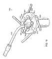
- FIGS. 6-8illustrates one embodiment of a retractor of the invention in three different positions or degrees of expansion.
- FIG. 6illustrates retractor 700 in a fully collapsed or contracted position.
- Retractor 700includes four retractor blades 702 , 704 , 706 , 708 and an expandable frame 710 having a major plane (parallel to plane XY).
- Retractor blades 702 , 704 , 706 , 708are attached at their respective proximal ends to expandable frame 710 .
- Retractor blades 702 , 704 , 706 , 708are arcuate or curved, and in this first position, their collective inner faces contact, thereby defining a conduit in the shape of a hollow cylinder.
- retractor 700In the contracted position illustrated in FIG. 6 , the inner diameter of access portal 712 , defined by base components 714 , 716 , 718 , 720 of expandable frame 710 , is reduced in size relative to its size in the positions illustrated in FIGS. 7 and 8 .
- Retractor 700includes four ratchet arms 722 , 724 , 726 , 728 and mechanisms for fixing the position of one base component relative to another base component that include ratchet release buttons 730 , 732 , 734 , 736 .
- Retractor 700is bisected by at least two planes that are substantially normal to the major plane.
- a first planeis parallel to the XZ plane and bisects retractor 700 , running approximately between base components 714 and 716 and between base components 718 and 720 .
- a second planeis parallel to the YZ plane and bisects retractor 700 , running approximately between base components 714 and 720 and between base components 716 and 718 .
- FIG. 7illustrates retractor 700 in a partially expanded, or partially translated, position.
- forceis applied to expandable frame 710 to move base component 714 along ratchet arm 722 and base component 718 along ratchet arm 726 .
- expandable frame 710moves approximately in, or parallel to, the major plane from a first position (i.e., the one illustrated in FIG. 6 ) to a second position (i.e., the one illustrated in FIG. 7 ) substantially along the first plane and generally away from the second plane.
- Ratchet arms 722 , 724 , 726 , 728are arcuate. Movement of base components 714 , 716 , 718 , 720 along arcuate ratchet arms 722 , 724 , 726 , 728 causes an asymmetric or uneven expansion and contraction of retractor 700 . That is, as expandable frame 710 expands, an average distance between the ends of ratchet blades 702 , 704 , 706 , 708 that are distal from expandable frame 710 increases more than the average distance between the ends proximal to expandable frame 710 and more than an average distance between base components 714 , 716 , 718 , 720 .
- this unequal expansionallows the distal ends of the retractor blades to retract deep tissue while reducing the size of an incision needed to accommodate the expandable frame.
- movement of the base componentsdoes not cause an asymmetric or uneven expansion and contraction of the retractor.
- the ratchet armsare straight, expansion and contraction of the expandable frame results in an equal amount of expansion and contraction of the distal ends of the blades.
- the shape of the ratchet armsis chosen in order to produce a desired degree of asymmetric expansion.
- ratchet arms 722 , 724 , 726 , 728causes base components 714 , 716 , 718 , 720 to move slightly out of the major plane as expandable frame 710 is moved to various positions or degrees of expansion and contraction.
- the base componentsare arranged in such a way that the expandable frame is substantially coplanar and arranged flat in the major plane.
- this inventionalso includes embodiments where one or more portions of the expandable frame is not substantially coplanar at one or more positions or degrees of expansion and contraction.
- FIG. 8illustrates retractor 700 in a position where expandable frame 710 is further expanded from the position illustrated in FIG. 7 .
- forceis applied to expandable frame 710 to move base component 716 along ratchet arm 724 and base component 720 along ratchet arm 728 , substantially along the major plane.
- expandable frame 710moves from the second position (i.e., the one shown in FIG. 7 ) to a third position (i.e., the one shown in FIG. 8 ) substantially along the second plane and generally away from the first plane.
- expandable frame 710is able to be expanded or contracted to many different positions by moving one or more of base components 714 , 716 , 718 , 720 along ratchet arms 722 , 724 , 726 , 728 , respectively. In this way, retractor 700 can be expanded or contracted to a wide variety of desired positions.
- Retractor 700illustrates a connector that includes ratchet arms 722 , 724 , 726 , 728 .
- FIG. 7illustrates ratchet arm 726 of base component 716 partially extending through neighboring base component 718 .
- ratchet arms 724 , 722 , and 728extend through or partially through base components 716 , 714 , and 720 , respectively.
- the connectorsconnect base components 714 , 716 , 718 , 720 and form expandable frame 710 .
- Retractor 700also illustrates a mechanism for fixing the position of a first base component relative to a second base component.
- FIG. 7illustrates ratchet release button 734 , which includes a series of teeth or grooves that engage a second series of complementary teeth or grooves on ratchet arm 726 , thereby fixing the position of base component 718 relative to ratchet arm 726 .
- ratchet release button 734fixes the position of base component 716 (i.e., the “first base component”) relative to base component 718 (i.e. the “second base component”).
- Pressing ratchet release button 734disengages the complementary teeth, and allows base component 718 to move along ratchet arm 726 and provides for the movement of base component 718 relative to base component 716 .
- the position of base component 716 relative to base component 714is adjustable by engaging or disengaging ratchet release button 732
- the position of base component 714 relative to base component 720is adjustable by engaging or disengaging ratchet release button 730
- the position of base component 720 relative to base component 718is adjustable by engaging or disengaging ratchet release button 736 .
- ratchet release buttons 736 and 732are pressed, thereby allowing expandable frame 710 to move along the second plane and generally towards the first plane.
- ratchet release buttons 734 and 730are used to adjust expandable frame 710 along the first plane and generally towards the second plane. In this manner, expandable frame 710 can be adjusted to one or more different positions, allowing retractor 700 to be expanded or contracted to a desired extent.
- the expandable frameincludes a connector that comprises one or more hinges which attach two or more base components.
- FIGS. 9-12illustrate four different views of retractor 900 .
- Retractor 900includes retractor blades 902 , 904 , 906 , 908 which are attached to expandable frame 910 .
- Expandable frame 910includes base components 912 , 914 , 916 , 918 .
- Each base component 912 , 914 , 916 , 918is constructed or formed from a continuous piece of material that includes each retractor blade 902 , 904 , 906 , 908 , respectively.
- Expandable frame 910includes ratchet arms 920 , 922 , which are attached to base components 918 , 916 , respectively.
- Ratchet arms 920extends from base component 918 into the accommodating hole of base component 912 , thereby connecting base component 918 to base component 912 .
- ratchet arm 922connects base component 916 to base component 914 .
- Retractor 900includes mechanisms for fixing the position of a first base component relative to a second base component that comprise ratchet release levers 924 , 926 .
- Ratchet release levers 924 , 926provides the same function as the ratchet release buttons illustrated previously and are used to release the positions of base component 914 relative to ratchet arm 922 and base component 912 relative to ratchet arm 920 , respectively.
- Expandable frame 910also includes a connector that comprise hinges 927 , 928 .
- Hinge 927rotatably connects base component 912 to base component 914 and hinge 928 rotatably connects base component 916 to base component 918 .
- Retractor 900also includes mechanisms for fixing the position of a first base component relative to a second base component that comprises levers 930 , 932 .
- Lever 930locks or immobilizes the rotation of hinge 927 , thereby fixing the position of base component 912 relative to base component 914 .
- Lever 932locks or immobilizes the rotation of hinge 928 , thereby fixing the position of base component 918 relative to base component 916 .
- Expandable frame 910defines access portal 934 .
- FIG. 10illustrates a top-down view of retractor 900 after expandable frame 910 has been moved from the first position, illustrated in FIG. 9 , to a second position.
- Ratchet arms 920 , 922are substantially straight and provide for movement of base component 912 relative to 918 and movement of base component 914 relative to base component 916 .
- Ratchet lever 926engages teeth 936 on the side of ratchet arm 920 , thereby fixing the position of base component 918 relative to base component 912 .
- ratchet lever 924engages teeth 938 on the side of ratchet arm 922 , thereby fixing the position of base component 916 relative to base component 914 .
- FIG. 11illustrates a side view of retractor 900 after expandable frame 910 has been moved from the second position to a third position by rotating about hinge 927 and hinge 928 (not shown in FIG. 11 ).
- Hinges 927 , 928provide for movement of base components 914 , 916 relative to base components 912 , 918 .
- the rotationresults in an average distance between distal ends of retractor blades 902 , 904 that is larger than both the average distance between the two proximal ends of retractor blades 902 , 904 and the average distance between the two base components 912 , 914 .
- FIG. 12illustrates an additional view of retractor 900 after expandable frame 910 has been moved to the third position.
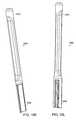
- one or more blades of a retractorinclude one or more blade extensions that are telescopically and slidably attached to the blade.
- the retractorincludes a blade extension fixation mechanism that, when engaged, immobilizes or secures the blade extension at a desired telescoped length.
- a blade extension fixation mechanismis one or more series of teeth or ridges on the blade and/or blade extension which slidably secure the extension to the blade.
- Another example of a blade extension fixation mechanismincludes a series of teeth on the blade and a tab on the blade extension. The tab engages the teeth on the blade to immobilize the blade extension. Applying force to the tab disengages it from the teeth and allows the blade extension to slide relative to the blade.
- Many other blade extension fixation mechanismsare encompassed by this invention, such as hooks, levers, latches, screws, locking mechanism, combinations thereof, and the like.
- the blade extension fixation mechanismscan include an automated mechanism, such as one or more motorized screws.
- a retractorincludes a mechanism for preventing the blade extension from disengaging from a blade as it moves relative to the blade.
- a mechanism for preventing the blade extension from disengaging from a bladeinclude one or more grooves or tracts on the blade and/or blade extension which slidably secure the extension to the blade. The grooves allow the extension to slide relative to the blade, but prevent the extension from disengaging from the blade.
- Many other mechanisms for preventing the blade extension from disengaging from a bladeare encompassed by this invention.
- the blade extensionincludes a telescope tab which provides a telescopic attachment point to ease the act of telescoping the blade extension.
- Blade 1300The inner face of blade 1300 is illustrated in FIGS. 13A , 13 B, and 13 C, with blade extension 1302 extending from distal end 1304 of blade 1300 at progressively longer telescopic lengths.
- Blade 1300includes an attachment mechanism that comprises clip 1306 at proximal end 1308 .
- Blade 1300includes blade extension fixation mechanism comprising two series of teeth 1310 which extend at least a portion of the length of blade extension 1302 .
- a complementary series of teethforcibly engage both tracts of teeth 1310 , keeping blade extension 1302 at a desired telescopic length.
- Blade extension 1302includes telescopic attachment point 1312 which protrudes through an opening in the inner face of blade 1300 .
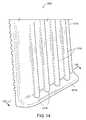
- one or more blades and/or blade extensionsinclude a toe-out protrusion extending from the distal end of the outer face.
- FIG. 14illustrates a close up view of distal end 1314 of the outer face of blade extension 1302 .
- Toe-out protrusion 1314extends from the outer face of blade extension 1302 .
- Toe-out protrusion 1314allows blade extension 1302 to more effectively retract tissue from a surgical site compared to a similar blade extension lacking a toe-out protrusion.
- Blade extension 1302also includes ridges 1316 which extend at least a portion of the length of blade extension 1302 , and provide more effective retraction of tissue from a surgical site compared to a similar blade extension lacking ridges.
- the toe-out protrusionextends at an angle from the face of the blade or blade extension at an angle (e.g., a right angle or an angle greater or lesser than 90°).
- the outer face of one or more blade and/or blade extensionsinclude a textured surface to assist the blades or extensions in gripping tissue. This provides for improved retraction of tissue at a surgical site.
- portions of the outer facescan have a rough texture, ridges (e.g., the ridges shown in FIG. 14 ), or similar surface textures.
- FIG. 15illustrates an embodiments of a retractor of the invention that includes blade extensions.
- Retractor 1500includes expandable frame 1502 in a fully expanded position with the greatest average distance between base components 1504 , 1506 , 1508 , 1510 .
- Blades 1512 , 1514 , 1516 , 1518includes blade extensions 1520 , 1522 , 1524 , 1526 , respectively.
- FIG. 15illustrates expandable frame 1502 at an expanded position without the blade extensions 1520 , 1522 , 1524 , 1526 telescoped from blades 1512 , 1514 , 1516 , 1518 , respectively.
- FIG. 16Aillustrates another embodiment of the invention that includes retractor 1600 .
- Retractor 1600includes expandable frame 1602 (which is at a slightly less expanded position than expandable frame 1502 illustrated in FIG. 15 ) and blade extensions 1620 , 1622 , 1624 , and 1626 partially telescoped from blades 1612 , 1614 , 1616 , and 1618 , respectively.
- Retractor 1600also comprises a plurality or connectors that include arms 1638 , 1640 , 1642 , and 1644 .
- FIG. 16Billustrates retractor 1600 with expandable frame 1602 in a contracted or condensed position and extensions 1620 , 1622 , 1624 , and 1626 partially telescoped from blades 1612 , 1614 , 1616 , and 1618 .
- Retractor 1600includes a plurality of universal attachment points, including attachment points or holes 1630 , 1632 , 1634 , and 1636 . Attachment holes 1630 , 1632 , 1634 , and 1636 can be used to attach surgical instruments, additional blades, retractor support structures (e.g., rigid arms), and the like.
- FIG. 16Cillustrates one perspective view of a portion of retractor 1600 that includes component 1608 , extension 1624 , and arm 1644 .
- FIG. 16Dillustrates another perspective view of a portion of retractor 1600 that includes component 1608 and extension 1624 .
- FIG. 16Eillustrates yet another perspective view of a portion of retractor 1600 that includes component 1608 , blade 1616 , and arm 1644 .
- extension 1624has been removed from blade 1616 .
- FIG. 16Fillustrates a perspective view of a portion of retractor 1600 that includes a disassembled view of the portion of retractor 1600 that is illustrated in FIG. 16E .
- Ratchet arm release button 1662is assembled to base component 1608 by using pin 1656 .
- Spring 1652provides sufficient force to engage arm 1642 (not illustrated in FIG. 16F ) and frustrate movement of component 1608 relative to arm 1642 , unless a practitioner depresses button 1662 .
- Retractore 1600is free to expand without pressing the buttons due to the ramping of the complementary teeth on the arms and buttons.
- the practitioner of the inventionpresses the buttons to disengage the teeth of the arms and buttons.
- Arm 1644is secured to base component 1608 with pin 1654 .
- Ratchet arm 1644includes a portion of a mechanism for securing the relative position of base component 1608 that includes teeth 1650 .
- FIG. 16Gillustrates another perspective view retractor 1600 that includes blade 1670 .
- Trapezoidal blade 1670is attached or assembled to arm 1642 .
- Handle 1672is used to assemble blade 1670 to retractor 1600 .
- a practitioner of the inventioncan use arm 1672 to assemble blade 1670 to retractor 1600 at attachment point 1632 (not illustrated in FIG. 16G ).
- blade 1670comprises an trapezoidal shape
- the blades of the retractors of the inventioncan comprise a form or a shape of blades known in the art.
- FIGS. 16H and 161illustrate two alternative blades 1672 and 1674 which are attached or assembled to arms 1676 and 1678 , respectively.
- an inserteris use to direct the retractors of the present invention to a desired location.
- FIG. 16Jillustrates a portion of the invention that includes inserter 1680 .
- Inserter 1680includes a plurality of attachment pins 1682 .
- Attachment pins 1682secure inserter 1680 to some or all of the attachment holes of the frame of the retractor of the invention.
- a practitioner of the inventionassembles or attaches inserter 1680 to a retractor of the invention and uses handles 1684 to position or direct retractor 1600 to a desired location within a mammalian anatomy.
- FIGS. 16K and 16Lillustrate perspective view of telescoping blade extender 1886 .
- Telescoping blade extender 1886includes distal end 1888 and proximal ends 1890 .
- a practitioneruses proximal ends 1890 to slide blade extension(s) 1620 , 1622 , 1624 , and/or 1626 with respect to blades 1612 , 1614 , 1616 , and 1618 to a desired location within a mammalian anatomy, respectively.
- FIG. 16Millustrates a perspective view of telescoping blade remover 1892 .
- Telescoping blade remover 1892includes distal end 1896 and proximal ends 1894 .
- a practitioneruses proximal ends 1894 to latch onto a blade extension and disengage it from a mammalian anatomy and/or reposition the extension to a desired location within a mammalian anatomy.
- the blades and blade extensions of this inventioncan be any size or shape desired.
- one or more blades or blade extensionsare shaped and/or sized for a specific task.
- a bladecan be shaped to retract muscle tissue, adipose tissue, nerve tissue, or other types of tissue.
- Examples of various blade with disparate trapezoidal shapesare illustrated in FIGS. 17A-17C .
- the blades illustrated in FIG. 17A-17Care just a few examples of trapezoidal geometries and this invention includes a wide range different blade shapes (e.g., blades with non-trapezoidal geometries).
- the retractors of this inventioninclude additional extensions at the distal ends of the blades or blade extensions.
- FIG. 17Dillustrate the distal end of blade 1700 , which includes pivoting extension 1702 that rotates about hinge 1704 .
- FIGS. 17E and 17Fillustrate another embodiment of an additional blade extension. Distal end of blade 1750 are slidably attached to two additional extensions 1752 by slides 1754 .
- additional extensionsare fixable into a desired position.
- one or more surgical instrumentsare attached to the retractor to provide additional utility.
- surgical instrumentsinclude surgical lighting source, a portion of a source for producing suction, or other surgical instruments that are known in the art.
- surgical instrumentsare attached to an expandable frame with a mechanism for supporting surgical instruments. The surgical instruments can be attached prior to, at some intermediate state of, or after the expansion of the retractor.
- the inner or outer face of the blades or blade extensionsinclude longitudinal grooves or tracts which can be used to slide or otherwise guide surgical instruments down the length of the blades or blade extensions and into or near a surgical site.
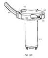
- FIG. 18illustrates retractor 1800 , which includes expandable frame 1802 .
- Expandable frame 1802includes base components 1804 , 1806 , 1808 , 1810 .
- Base components 1804 , 1806 , 1810define attachment holes 1812 , 1814 , 1816 , respectively.
- Light source 1818is attached to base component 1808 with a mechanism for supporting surgical instruments that comprises instrument clip 1820 at an attachment hole on base component 1808 .
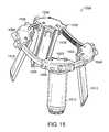
- FIG. 19illustrates retractor 1900 which includes expandable frame 1902 .
- Expandable frameincludes base components 1904 , 1906 , 1908 , 1910 .
- Base components 1904 , 1906 , 1908 , 1910define attachment hole 1912 .
- Attachment hole 1912provides an attachment site for instrument clips 1914 , 1916 .
- Instrument clips 1914 , 1916secure instruments, such as surgical lighting source 1918 , to the expandable frame.
- FIG. 20illustrates attachment of additional blades to retractor 2000 , which includes base components 2002 , 2004 .
- Base components 2002 , 2004are attached to expandable frame 2006 along exposed ratchet arms, such as ratchet arm 2008 .
- Base component 2004includes blade 2010 and ratchet release buttons 2012 .
- Ratchet release buttons 2012secure base component 2004 at a relative position to ratchet arm 2008 .
- FIGS. 21A-21Dillustrates retractor 4000 which is yet another embodiment of a retractor of the invention.
- FIG. 21Aillustrates retractor 4000 in a first position in which the retractor is fully collapsed or contracted position.
- FIG. 21Billustrates retractor 4000 in a second position in which the retractor has been expanded or opened.
- FIG. 21Cillustrates another view of retractor 4000 in the second position.
- FIG. 21Dillustrates a bottom view of retractor 4000 in the second position.
- Retractor 4000includes expandable frame 4010 having a major plane parallel to the XY plane. Expandable frame 4010 comprises a first base component 4014 , a second base component 4016 , a third base component 4018 , and a fourth base component 4020 . While retractor 4000 is illustrated in FIGS. 21A-21D as having four base components, in other embodiments, the retractor comprises two, three, or more than four base components. Optionally, retractor 4000 includes at least one mechanism for supporting surgical instruments (not illustrated in FIGS. 21A-21D ). Examples of suitable mechanisms for supporting surgical instruments include those that are described herein, such as instrument clips similar to that illustrated in relation to FIGS. 1 , 2 , and 18 , or attachment grooves.
- Base components 4014 , 4016 , 4018 , 4020are connected to one another using connectors that include two rods 4022 , 4024 .
- Rod 4022connects first base component 4014 , second base component 4016 and fourth base component 4020
- rod 4024connects second base component 4016 , third base component 4018 , and fourth base component 4020 .
- Rods 4022 and 4024extend completely through first base component 4014 and third base component 4018 , respectively. In the position illustrated in FIG. 21A , rods 4022 and 4024 also extend completely through second base component 4016 and third base component 4020 , respectively.
- Base components 4016 and 4020can translate along a length of rods 4022 and 4024 .
- Base component 4014can translate along a length of rod 4022 and base component 4018 can translate along a length of rod 4024 .
- the retractoralso includes one or more mechanisms for fixing the position of one base component (not illustrated in FIGS. 21A-21D ) relative to another base component.
- suitable mechanisms for fixing the position of one base component relative to another base componentare described herein, and include the mechanisms for fixing the position of one base component relative to another base component that are illustrated in FIGS. 1-3 , 6 - 8 , and 9 - 12 , as well as other ratchet, screw, or retaining mechanisms.
- Retractor 4000includes retractor blades 4002 , 4004 , 4006 , and 4008 , which are attached to base components 4016 , 4018 , 4014 , and 4020 , respectively.
- Retractor blades 4002 , 4004 , 4006 , 4008are arcuate or curved, and in the first position illustrated in FIG. 21A , their collective inner faces contact, thereby defining a conduit in the shape of a hollow circular cylinder having a smooth or substantially seamless profile.
- the conduitcan be an elliptical cylinder.
- retractor 4000includes a radiolucent material.
- a portion of the retractorcan include radiolucent plastics, aluminum, thin stainless steel, titanium, nitinol, or cobalt chrome.
- the retractor bladescan include integral sleeve inserts.
- a retractor bladecan include a blade extension that is telescopically and slidably attached to a retractor blade.
- the retractorcan also include a blade extension fixation mechanisms that, when engaged, immobilizes a blade extension relative to the remainder of the retractor blade. Examples of blade extensions and fixation mechanisms are described herein, such as in relation to FIGS. 13A-13C , 16 , and 17 D- 17 F.
- one or more of the retractor bladeshas a toe-out protrusion which allows the blades to grip tissue and provides for better retraction of tissue. Examples of such a toe-out protrusion are described herein, such as in relation to FIG. 14 .
- the major axis of retractor blades 4002 , 4004 , 4006 , 4008are normal to the major plane of the expandable frame.
- one or more of the bladesare attached to the expandable frame such that the blade is rotatable about the major axis of the blade and fixable at a desired point of rotation about the major axis.
- a bladecan be attached to the base component with a vertical hinge that allows the blade to be rotated from side to side.
- one or more of the bladesare attached to the expandable frame in such a way that the blade is rotatable about an axis that is parallel to the major plane of the expandable frame.
- a bladecan be attached to the base component with a horizontal hinge that allows the blade to be rotated up and down.
- Retractor 4000is bisected by at least two planes that are substantially normal to the major plane XY.
- a first planeis parallel to the XZ plane and bisects retractor 4000 , running approximately between base components 4014 and 4018 and bisects base components 4016 and 4020 .
- a second planeis parallel to the YZ plane and bisects retractor 4000 , running approximately between base components 4016 and 4020 and bisects base components 4014 and 4018 .
- the inner diameter of access portal 4012defined by base components 4014 , 4016 , 4018 , 4020 of expandable frame 4010 , is reduced in size relative to its size in the positions illustrated in FIGS. 21B-21D .
- retractor 4000can be expanded or deployed.
- a spreader instrument(such as the one described in relation to FIGS. 26-28 ) can be used to open the distal ends of the retractor blades.
- Retractor 4000can be used to retract and hold muscle at an angle that is about perpendicular to the greatest muscle force, thereby allowing for better or optimal placement of retractor blades due to anatomical constraints and reducing the problems associated with tissue creep which are caused by muscle and other tissue not being restrained from the working channel.
- FIG. 21Billustrates retractor 4000 in a partially expanded, or partially translated, position.
- forceis applied to expandable frame 4010 to move base component 4016 along rod 4022 and relative to base component 4020 and rod 4024 .
- a stoplocated at the ends of rods 4022 and 4024 prevents attached components from translating off of the ends and disengaging the rods.
- Base components 4014 and 4018can be slideably positioned at a desired position along rods 4022 or 4024 , respectively. In this manner, expandable frame 4010 moves approximately in, or parallel to, the major plane from a first position (i.e., the one illustrated in FIG.
- rods 4022 , 4024can be secured to rods 4022 , 4024 .
- expandable frame 4010is able to be expanded or contracted to many different positions by moving one or more of base components 4014 , 4016 , 4018 , 4020 along one of rods 4022 , 4024 . In this way, retractor 4000 can be expanded or contracted to a wide variety of desired positions.
- Rods 4022 , 4024are straight, so movement of the base components does not cause an asymmetric or uneven expansion and contraction of the retractor.
- expansion and contraction of the expandable frameresults in an equal amount of expansion and contraction of the distal ends of the blades and the base components remain coplanar with one another or arranged flat in the major plane XY.
- the shape of the rods or other connectoris chosen in order to produce a desired degree of asymmetric or curved expansion such that the expandable frame defines an access portal having an average diameter that is smaller than the greatest distance between the distal ends of any two blades when the expandable frame is in the second position.
- one or more portions of the expandable frameare not substantially coplanar at one or more positions or degrees of expansion and contraction.
- the blades and/or blade extensionsadd additional structural rigidity to the expandable frame when the expandable frame is at one or more positions.
- interlocking blades or blade extensionscan be mechanically connected to one another along some portion of their edges or sides, thereby providing additional structural rigidity.
- the retractors of this inventioncan be constructed of many different types of material, including a wide range of polymers, metals (e.g., titanium), and metal alloys (e.g., stainless steel, cobalt chrome, and titanium alloys). Some portions of the retractor may require a strong, rigid material (e.g., the bases, ratchet arms, and hinges of the expandable frame). Other portions of the retractor may require a flexible, durable material in order to withstand repeated distortions (e.g., a flexible tab of a fixing mechanism). Preferably, the materials of construction are biocompatible.
- the materials of constructioncan be chosen to provide favorable characteristics or lend additional advantages during some portion of the surgical process. For example, it is often necessary to take X-ray images and/or fluorimages of a subject during surgery.
- at least a portion of the retractoris constructed of radiolucent materials.
- this inventionincludes a method of forming a surgical site in an organism (e.g., a human or other mammal).
- the methodcomprises the steps of a) creating an incision in the skin of a mammal; b) retracting the tissue of the mammal at the incision with a retractor of this invention to form a surgical site.
- the surgical siteis formed at a spinal column.
- the surgical siteis formed during a surgical procedure that includes at least one member of the group consisting of a transforaminal lumbar interbody fusion procedure, a posterior lumbar interbody fusion procedure, a posterolateral fusion procedure, and other approaches (e.g., anterior, lateral, anterior-lateral, and other areas of the spine such as, for example, cervical or thoracic areas).
- the retractors of this inventionare also suitable for use in nonspinal surgical procedures.
- an obtruatoris inserted into the incision before the retractor is inserted.
- one obtruator and subsequent dilatorsare inserted to dilate the incision before the retractor is inserted.
- the retractoris assembled to an insertion tube before it is inserted into the organism.
- An insertion tubeprovides for easier insertion of a retractor into, and positioning within, an organism.
- the insertion tubeattaches to the expandable frame of a retractor.
- the retractoris inserted over an obtruator during insertion of the retractor to the depth of the surgical site or near the depth of the surgical site to be formed.
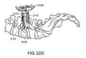
- FIGS. 22A-22Hillustrate one embodiment of such a method used to retract tissue near the spine of a human. Soft tissue and some bone mass has been omitted from the figures for clarity.
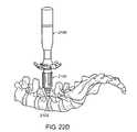
- FIG. 22Aillustrates obtruator 2100 after it has been inserted into an incision and forced down to the surgical site (i.e., next to the spinal column).
- the obtruatoris directed along a guide wire which has previously been tethered to the surgical site.
- retractor 2104is assembled to insertion tube 2106 .
- the combined assembly of retractor 2104 and insertion tube 2106defines a conduit that has an inner diameter that is greater than the outer diameter of obtruator 2100 . This allows the combined assembly of retractor 2104 and insertion tube 2106 to, in turn, be assembled over obtruator 2100 , as shown in FIG. 22B .
- retractor 2104is assembled over obtruator 2100 , a surgeon or other practitioner of this embodiment pushes retractor 2104 down the length of obtruator 2100 to surgical site 2102 by applying force on insertion tube 2106 , as shown in FIG. 22C .
- retractor 2104is at surgical site 2102 , obtruator 2100 is removed from the incision, leaving retractor 2104 in the incision and attached to insertion tube 2106 , as shown in FIG. 22D .
- Outer sleeve 2110contacts the frame and is used to position retractor 2104 to a desired depth and position (e.g., to the surgical site or above the surgical site to allow sufficient room for extension of the blade extensions). Alternatively or in addition, outer sleeve 2110 captures the proximal end of the blades that are inserted into the dovetail feature of the proximal end of retractor 2104 .
- Inner sleeve 2108is used to insert blades and/or blade extensions onto the retractor or to extend one or more blade extensions to a desired extent. Alternatively or in addition, inner sleeve 2108 is used to capture the distal end of the blade to prevent the blades from splaying when inserted into the incision.
- one or more blade extensions 2112can be extended to a desired extent around the surgical site 2102 , as shown in FIG. 22G .
- blade extensions 2112are attached to the outer face of the blades of retractor 2104 , however, in some embodiments, the blade extensions are attached to the inner face of the blades.
- the expandable frame of retractor 2104is moved to a desired position, such as the one shown in FIG. 22H .
- the surgical siteis formed by the distal ends of the blades and/or blade extensions 2112 .
- the retractoris attached to a surgical retractor positioning mechanism (e.g. one or more a rigid arms, not shown) which rigidly secures the retractor in the desired location.
- FIG. 24illustrates another embodiment of an insertion tube.
- Insertion tube 2300includes attachment portions 2302 , handle portion 2304 , and stop 2306 , all of which serve similar functions to the analogous portions in the embodiment of FIG. 23 .
- insertion tube 2300includes blade extension portion 2308 , which includes one or more extender tabs 2310 , which are mechanically connected to blade extender attachments 2312 .
- blade extension portion 2308which includes one or more extender tabs 2310 , which are mechanically connected to blade extender attachments 2312 .
- By pushing sliding extender tabs 2310a practitioner can lengthen blade extender attachments 2312 which are mechanically couple with one or more blade extensions in an attached retractor. In this manner, insertion tube 2300 allows a practitioner to insert a retractor, position a retractor, and/or extend one or more blade extenders to a desired telescopic length.
- a retractor of the inventionis assembled (e.g., mechanically attached, or slipped or positioned over) to one or more obtruator and dilators before insertion into an organism.
- FIG. 25illustrates such an assembly.
- Assembly 2400includes retractor 2402 , an insertion tube 2404 , an obtruator 2406 , and dilators 2408 and 2410 .
- FIG. 26illustrates one embodiment of a distraction instrument.
- Distraction instrument 2500has an attachment portion 2502 and a gripping portion 2504 . Applying force to gripping portion 2504 causes attachment portion 2502 to splay or expand. By connecting attachment portion 2502 to a retractor, the application of force to the gripping portion will move an expandable frame into a desired position.
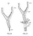
- the attachment portionis attached to the outer diameter of the retractor, while in other embodiments it is attached to an inner diameter of the retractor (as illustrated in FIGS. 27 and 28 ).
- the expandable frameis expanded or contracted with the use of one or more keys or screws that engage the teeth on one or more ratchet arms and cause one or more base components to move relative to a ratchet arm. This provides for independent adjustment or each ratchet arm to a desired position or desired extent of expansion.
- FIG. 27illustrates the attachment of distraction instrument 2600 to retractor 2602 .
- Attachment portion 2604attaches to an inner diameter of access portal 2606 of expandable frame 2608 .
- Squeezing gripping portion 2610 togethercauses attachment portion 2604 to splay, as illustrated in FIG. 28 , thereby moving expandable frame 2608 into a desired position.
- this inventionincludes a method of forming a surgical site in an organism.
- the methodcomprises the steps of creating an incision in the organism and retracting the tissue of the organism at the incision with a retractor of the invention to form a surgical site, thereby forming a surgical site defined at least in part by the distal ends of the blades.
- the organismis a mammal. In further embodiments, the mammal is a human.
- the surgical siteis formed near a spinal column.
- a surgical siteis formed during a surgical procedure that includes at least one member of the group consisting of a transforaminal lumbar interbody fusion procedure, a posterior lumbar interbody fusion procedure, and a posterolateral fusion procedure.
- the incisionis first dilated with at least one obtruator before inserting the retractor.
- a retractoris inserted over the obtruator during insertion of the retractor to the depth of the surgical site to be formed.
- the retractoris attached to a surgical retractor positioning mechanisms that rigidly secures the retractor in a desired location.
- a positioning mechanismis an adjustable rigid arm that attaches to a surgical table.
- this inventionincludes an assembly comprising a surgical retractor assembled to at least one obtruator.
- this inventionincludes a surgical retractor which is mechanically attached to an obtruator.
- the surgical retractoris not mechanically or rigidly attached to an obtruator, but is positioned or slid over an obtruator.
- this inventionincludes a surgical retractor, comprising an expandable frame that includes at least two base components, and at least one connector that connect the base components, wherein at least one base component is moveable along the connector; and at least two retractor blades attached to the expandable frame, wherein each blade has a proximal end attached to expandable frame, a distal end opposite the proximal end, and a major axis.
- the expandable framemoves from a first position to a second position, thereby increasing the average distance between two base components to a first distance and increasing the average distance between the distal ends of two retractor blades to a second distance, wherein the first distance is less than the second distance.
- this inventionincludes a surgical retractor, comprising an expandable frame that includes at least two base components, and at least one connector that connect the base components, wherein at least one base component is moveable along the connector; and at least two retractor blades attached to the expandable frame, wherein each blade has a proximal end attached to expandable frame, a distal end opposite the proximal end, a major axis, and an outer face.
- the expandable framemoves from a first position to a second position, thereby increasing the average distance between two base components.
- the combined outer faces of the retractor bladeare cylindrical when the expandable frame is in a first position.
- this inventionincludes a surgical retractor, comprising a housing component having a central axis and including a cylindrical portion, wherein the cylindrical portion defines a conduit having an inner diameter normal to the central axis; and a blade portion that is contiguous with one end of the cylindrical portion, wherein the blade portion includes at least two blades, wherein a distal portion of each blade is moveable relative to the central axis; and a cylindrical expander component having an outer diameter, wherein the outer diameter is smaller than the inner diameter of the cylindrical portion and the expander component is movably attached to the housing component.
- At least one bladeincludes a tow-out protrusion.
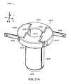
- FIGS. 29 and 30illustrates one embodiment of a retractor of the invention.
- FIG. 29illustrates retractor 2800 in a first position.
- Retractor 2800comprises housing component 2802 that has central axis 2804 .
- Housing component 2802includes cylindrical portion 2806 which defines a conduit having inner diameter 2808 normal to central axis 2804 .
- Blade portion 2810is contiguous with one end of cylindrical portion 2806 and includes blades 2812 .
- Blades 2812have distal portions 2814 that is moveable relative to central axis 2804 .
- Cylindrical expander component 2816is movably attached to housing component 2802 by screw threads 2818 .
- Cylindrical expander component 2816includes a blade expansion mechanism that comprises an extension 2820 that extends down the inner walls of cylindrical portion 2806 .
- FIG. 29illustrates retractor 2800 in a first position, where distal ends 2814 are proximate to one another.
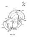
- FIG. 30illustrates retractor 2800 after expander component 2816 has been rotated relative to housing component 2802 . Such rotation causes expander component 2816 to press along screw threads 2818 , pressing extension 2820 into the inner wall of blade portion 2810 and causing blades 2812 to move radially from central axis 2804 , thereby expanding a surgical site.
- distal ends 2814were proximate to each other and blade portion 2810 formed a cone.
- distal ends 2814are splayed or distant from each other and central axis 2804 .
- the conical shape of blade portion 2810allow retractor 2800 to be easily inserted into an organism (e.g., through an incision) with a minimum of trauma to surrounding tissue. Once in a desired location, retractor 2800 can be expanded to the second position, thereby forming a surgical site and providing a practitioner access to that site.
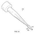
- FIG. 31illustrates retractor 3000 , with distal ends 3002 in a first position.
- FIG. 32illustrates retractor 3000 with distal ends 3002 in a second position.
- FIG. 33illustrates retractor 3000 with attached expander component 3004 .
- this inventionincludes a method of performing surgery on an organism, comprising the steps of creating an incision in the organism, retracting the tissue surrounding the incision with a retractor to form a surgical site, and performing a surgical procedure at the surgical site.
- an illuminated surgical cannulacomprises a surgical cannula that has an outer diameter, an inner diameter, a distal end, and a proximal end, wherein the inner diameter, the distal end, and the proximal end define an interior area; and an interface ring attached to the proximal end, wherein the interface ring includes a light source interface mechanism in photonic communication with an array of fiber optic wire, wherein the array is arranged to direct light towards the distal end of the cannula.
- the interior areais illuminated by the light source.
- the interface ringincludes a light source (e.g., a led light or some other light source).
- the cannulaincludes at least one fiber optic wire that is in photonic communication with the array of the interface ring at the proximal end and extends down at least a portion of the length of the cannula towards the distal end. In a further embodiment, at least a portion of the fiber optic wire is embedded in the cannula between the outer and inner diameters.
- FIG. 34illustrates one embodiment of an interface ring.
- Interface ring 3300includes a light source interface mechanism 3302 .
- Light source interface mechanism 3302directs light from an outside light source (e.g. a light source commonly used in an operating procedure) to an array 3304 of fiber optic wire 3306 .
- Interface ring 3300defines access portal 3308 that provides a practitioner access to an attached cannula.
- Array 3304is disposed around interface ring 3300 and projects light down the length of a cannula.
- array 3304directs light to a cannula that comprises at least a portion of a light-conducting material.
- an interface ringforms a complete circle and fits on top of a cannula or retractor of the invention.
- an interface ringforms a portion of a circle (e.g., a half circle or a quarter circle) and fits on top of a cannula or retractor of the invention.
- FIG. 35illustrates a portion of a cannula that includes a light-conducting material.
- Cannula 3400includes a plurality of fiber optic wires 3402 .
- Fiber optic wire 3402are embedded within the material forming the wall of cannula 3400 .
- FIG. 36illustrates interface ring 3300 assembled to a portion of a cannula 3400 .
- the cannula illustrated in the figuresis just one embodiment of a cannula of the invention.
- the illuminated cannula, or portions thereof (e.g., an interface ring),can be used with any retractor of the invention.
- this inventionfeatures methods of performing surgical procedures on the spine of a human using retractors of the present invention.
- FIGS. 37A-37Uillustrate embodiments of the invention that include a method of using a retractor (e.g., a retractor of the invention) during a surgical procedure on the spine of a human and related instruments and tools of the invention.
- a retractore.g., a retractor of the invention
- FIG. 37Aillustrates patient 3702 in a prone position on table 3704 (e.g., a Jackson Table or other table used for image procedures) in such a way so as to provide an unrestricted view for imaging.
- table 3704e.g., a Jackson Table or other table used for image procedures
- a framee.g., a Wilson frame
- socketse.g., a Clark Socket
- FIG. 37Aillustrates patient 3702 in a prone position on table 3704 (e.g., a Jackson Table or other table used for image procedures) in such a way so as to provide an unrestricted view for imaging.
- a framee.g., a Wilson frame
- socketse.g., a Clark Socket
- the multifidus and longisimus muscles that run parallel to the spineare dilated.
- fluoroscopyis used to locate a desired level and close attention is made to keep the targeted surgical site at the center of the fluoroscopic view.
- the center of the targetis generally the medial border of the facet joint of the desired disc level.
- An incision templatemay be used (with or without fluoroscopic guidance) to locate the incision's center over the disc space of the proper level to be operated on. Pressing the retractor into the skin of patient 3702 will make an imprint and provide a good indication of the size of the needed incision.
- a longitudinal incision slightly larger than the retractor of the inventione.g., a retractor of the invention that is in a semi- or fully-contracted or condensed form
- the retractor of the inventione.g., a retractor of the invention that is in a semi- or fully-contracted or condensed form
- only the skinis incised since dilators can be used to pierce and dilate the fascia.
- a dilatoris inserted into the incision, bluntly piercing the fascia to dilate the paravertebral muscle tissue down to the laminar level, as illustrated in FIG. 37B .
- the fasciais incised prior to the insertion of the first dilator.
- the dilator's positionmay be confirmed fluoroscopically. With careful tactile sensation, the paravertebral muscles are swept free from the lamina, base of the spinous process, and over the facet joint with a gentle wanding motion along line 3716 , thereby facilitating visualization and ensuring the subsequent dilators and retractor is fully seated against the facet.
- sequential dilationis performed by passing the next largest dilator 3710 over dilator 3706 and directed down to surgical site 3708 .
- dilator 3712is then passed over dilator 3710 and then dilator 3714 is passed over dilator 3712 .
- an introduceris utilized to insert the larger dilators.
- depth measurementsare taken from the where the skin contacts the dilator.
- the depthis most effectively measures with dilators 3710 or 3712 , as these dilators will be flush to the bone and produce the most accurate measurement.
- a retractor of the inventionis directed to surgical site 3708 .
- the retractoris directed to surgical site 3708 with an open Wiltse approach where the natural muscle plane is located through a mobilized midline incision or a lateral incision.
- FIG. 37Dillustrates assembled retractor 3730 .
- Retractor 3732includes base components 3734 , 3736 , 3738 , and 3740 .
- FIG. 37Eillustrates one step of the assembly process.
- Base component 3740includes arm 3742 .
- Base component 3734includes arm 3744 and defines arm hole 3750 .
- Release button 3752is depressed to disable the locking mechanism of component 3734 , and arm 3742 is directed through hole 3750 , thereby connecting or assembling component 3740 to component 3734 .
- component 3736is assembled to component 3738 .
- FIG. 37Eillustrates blade depth tower 3760 can be used to assist a practitioner of the invention in extending the blade extensions.
- Tower 3760includes ring 3762 which is assembled to shaft 3766 .
- Shaft 3766includes two series of markings (each corresponding to a different sized retractor) on shaft 3766 .
- Ring 3762is rotated, causing ring 3762 to translated up or down the length of shaft 3766 .
- a practitioner of the inventionrotates ring 3762 to a position along shaft 3766 .
- the markings on shaft 3766are used to determine the desired position.
- retractor 3730is directed over top end 3764 of shaft 3766 and down to ring 3730 .
- Top end 3764engages the blade extensions of retractor 3730 and extends them as retractor 3730 is directed down to ring 3762 .
- one or more rigid arms 3770can be attached or secured to retractor 3730 , as illustrated in FIG. 37L .
- Rigid arm 3770is secured to the surgical table and is attached to retractor 3730 at one of the attachment holes on the expandable frame. Rigid arm 3770 can be adjusted during the surgical procedure, thereby allowing a practitioner of the invention to direct retractor 3730 to a desired position.
- Dilators 3706 , 3710 , 3712 , and 3714are removed from patient 3702 , as illustrated in FIG. 37M . During removal of the dilators, care should be taken to ensure retractor 3730 remains fully seated against the lamina and facet to prevent creep of soft tissue.
- electrocauteryis used to remove any remaining muscle attached to the bone inside of the inserted retractor, thereby preventing or reducing bleeding from the tissue.
- the bonecan be gently palpated with an inactive, extended length bovie tip to ensure that it is against bone.
- a pituitary rongeurcan be used to pluck the fragments out of the exposure. Irrigation is optionally sued to ensure adequate visualization during these maneuvers.
- retractor 3732can be expanded using distractor instrument 3772 , as illustrated in FIG. 37N .
- Retractor 3732can be expanded in the cephlad-caudal and/or the medial-lateral directions by inserting instrument 3772 into the top of retractor 3732 and squeezing the handle of instrument 3772 to the desired extent.
- the teeth of the locking mechanism of the expandable frameallow for micro adjustment and will hold retractor 3732 at the expanded position.
- the distractor instrumentis used parallel to the curved racks to avoid undue stress on the retractor.
- blade pusher 3774may be used to deploy the telescoping blade extensions further to, for example, prevent soft tissue creep in the working space.
- FIG. 370illustrates a practitioner of the invention deploying the extensions with pusher 3774 .
- FIGS. 37P-37Rillustrate a practitioner of the invention removing or adjusting a blade extension upward with blade remover 3776 .
- FIGS. 37Q and 37Rillustrate a close-up view of remover 3776 engaging blade extension 3778 .
- Blade remover 3776is inserted into the tooth of telescoping blade extension 3778 and the handle of remover 3776 is moved outward to relieve the locking mechanism of extension 3778 , as illustrated in FIG. 37R . This allows extension 3778 to be removed and/or adjusted upward, as illustrated in FIG. 37P .
- FIGS. 37S-37Uillustrate such attachments.
- FIG. 37Sillustrates the attachment of medial-lateral blade 3780 to a portion of retractor 3730 that includes an attachment point of a base component of retractor 3730 .
- FIG. 37Tillustrates a top view of retractor 3730 after blade 3780 assembled to retractor 3730 .
- Blade 3780is secured to an attachment point and is supported by a portion of an arm.
- FIG. 37Uillustrates light source 3782 attached to retractor 3730 . If desired, light source 3782 is adjusted inward or outward, depending on the amount of expansion of retractor 3730 .
- this inventionincludes a surgical method comprising incising tissue of a mammal to create an incision, expanding the incision to create a pathway from the incision to a surgical site, directing a retractor (e.g., a retractor of the invention) into the pathway, creating a working channel, and performing at least a portion of a surgical procedure through the working channel.
- a retractore.g., a retractor of the invention
- the working channelcan be created by, for example, expanding the retractor by separating a first retractor blade from a second retractor blade by moving at least one of the first retractor blade and the second retractor blade along a first connector of the retractor, and separating a third retractor blade from a fourth retractor blade by moving at least one of the third retractor blade and the fourth retractor blade along a second connector, wherein the second connector is oriented at an angle to the first connector.
- this inventionprovides methods of providing access to vertebrae.
- the methodcomprises incising tissue of a mammal to create an incision, expanding the incision to create a pathway from the incision to a surgical site, directing a retractor (e.g., a retractor of the invention) into the pathway, creating a working channel through the retractor by separating at least two retractor blades, performing at least a portion of a surgical procedure through the working channel at a first vertebra, exposing a second vertebra that is adjacent to the first vertebra by directing an instrument or implant between two of the retractor blades to displace tissue adjacent to the second vertebra; and performing at least a portion of a surgical procedure through the working channel at the second vertebra.
- a retractore.g., a retractor of the invention
- the tissue adjacent to the second vertebracan be displaced by directing an instrument or implant between two of the retractor blades and cutting or moving the tissue away from near the second vertebra, thus allowing a practitioner to access two vertebrae without the need to increase the incision in the skin of a mammal and/or create a second incision in the skin of a mammal.
- the first, second, third, and/or fourth retractor bladesare moved along a nonlinear line (e.g., an acute line). In other embodiments, the blades are moved along a linear line (i.e., a straight line).
- this inventionincludes a kit comprising a surgical retractor, a retractor inserter that can be assembled to a frame of the retractor, a blade depth tower, a distractor, and at least one blade adjustment instrument (e.g., one of the instruments mentioned previously, such as, for example, a blade remover instrument, a blade pusher instrument).
- the kitincludes at least one obtruator and at least two dilators (e.g., two or more dilators of dissimilar diameter).
- the kitincludes at least portions of an attachment device (e.g., portions of a rigid attachment arm).
Landscapes
- Health & Medical Sciences (AREA)
- Life Sciences & Earth Sciences (AREA)
- Surgery (AREA)
- Heart & Thoracic Surgery (AREA)
- Engineering & Computer Science (AREA)
- Biomedical Technology (AREA)
- Nuclear Medicine, Radiotherapy & Molecular Imaging (AREA)
- Medical Informatics (AREA)
- Molecular Biology (AREA)
- Animal Behavior & Ethology (AREA)
- General Health & Medical Sciences (AREA)
- Public Health (AREA)
- Veterinary Medicine (AREA)
- Pathology (AREA)
- Surgical Instruments (AREA)
Abstract
Description
Claims (15)
Priority Applications (2)
| Application Number | Priority Date | Filing Date | Title |
|---|---|---|---|
| US11/016,549US8038611B2 (en) | 2003-12-18 | 2004-12-17 | Surgical methods and surgical kits |
| US13/220,752US8622897B2 (en) | 2003-12-18 | 2011-08-30 | Surgical methods and surgical kits |
Applications Claiming Priority (2)
| Application Number | Priority Date | Filing Date | Title |
|---|---|---|---|
| US53056503P | 2003-12-18 | 2003-12-18 | |
| US11/016,549US8038611B2 (en) | 2003-12-18 | 2004-12-17 | Surgical methods and surgical kits |
Related Child Applications (1)
| Application Number | Title | Priority Date | Filing Date |
|---|---|---|---|
| US13/220,752ContinuationUS8622897B2 (en) | 2003-12-18 | 2011-08-30 | Surgical methods and surgical kits |
Publications (2)
| Publication Number | Publication Date |
|---|---|
| US20050159650A1 US20050159650A1 (en) | 2005-07-21 |
| US8038611B2true US8038611B2 (en) | 2011-10-18 |
Family
ID=34710169
Family Applications (5)
| Application Number | Title | Priority Date | Filing Date |
|---|---|---|---|
| US11/016,549Expired - Fee RelatedUS8038611B2 (en) | 2003-12-18 | 2004-12-17 | Surgical methods and surgical kits |
| US11/016,347Active2026-05-16US7491168B2 (en) | 2003-12-18 | 2004-12-17 | Surgical retractor systems and illuminated cannulae |
| US12/241,963Active2027-05-10US8602984B2 (en) | 2003-12-18 | 2008-09-30 | Surgical retractor systems and illuminated cannulae |
| US13/220,752Expired - LifetimeUS8622897B2 (en) | 2003-12-18 | 2011-08-30 | Surgical methods and surgical kits |
| US14/072,211Active2025-11-13US10869657B2 (en) | 2003-12-18 | 2013-11-05 | Surgical retractor systems and illuminated cannulae |
Family Applications After (4)
| Application Number | Title | Priority Date | Filing Date |
|---|---|---|---|
| US11/016,347Active2026-05-16US7491168B2 (en) | 2003-12-18 | 2004-12-17 | Surgical retractor systems and illuminated cannulae |
| US12/241,963Active2027-05-10US8602984B2 (en) | 2003-12-18 | 2008-09-30 | Surgical retractor systems and illuminated cannulae |
| US13/220,752Expired - LifetimeUS8622897B2 (en) | 2003-12-18 | 2011-08-30 | Surgical methods and surgical kits |
| US14/072,211Active2025-11-13US10869657B2 (en) | 2003-12-18 | 2013-11-05 | Surgical retractor systems and illuminated cannulae |
Country Status (7)
| Country | Link |
|---|---|
| US (5) | US8038611B2 (en) |
| EP (2) | EP2332468B1 (en) |
| JP (2) | JP4717828B2 (en) |
| CN (1) | CN1913834B (en) |
| AU (2) | AU2004303424C1 (en) |
| CA (1) | CA2550605C (en) |
| WO (1) | WO2005060837A2 (en) |
Cited By (30)
| Publication number | Priority date | Publication date | Assignee | Title |
|---|---|---|---|---|
| US20080114208A1 (en)* | 2006-09-22 | 2008-05-15 | Alphatec Spine, Inc. | Retractor |
| US20110034781A1 (en)* | 2009-08-05 | 2011-02-10 | Thomas Stuart Loftus | Retractor component system and method of using same |
| US20120259177A1 (en)* | 2011-04-05 | 2012-10-11 | Warsaw Orthopedic, Inc. | Overlapping Retractor Blade Assemblies |
| US20120277757A1 (en)* | 2011-04-13 | 2012-11-01 | Curax, Llc | Multi-function cannulated surgical device |
| US8517935B2 (en) | 2006-01-04 | 2013-08-27 | DePuy Synthes Products, LLC | Surgical retractors and methods of minimally invasive surgery |
| WO2013148678A1 (en)* | 2012-03-30 | 2013-10-03 | DePuy Synthes Products, LLC | Methods and devices for tissue retraction |
| US8550995B2 (en) | 2006-01-04 | 2013-10-08 | DePuy Synthes Products, LLC | Surgical access devices and methods of minimally invasive surgery |
| US8622897B2 (en) | 2003-12-18 | 2014-01-07 | DePuy Synthes Products, LLC | Surgical methods and surgical kits |
| US20140114139A1 (en)* | 2012-10-24 | 2014-04-24 | Blackstone Medical, Inc. | Retractor device and method |
| US20140114137A1 (en)* | 2012-10-23 | 2014-04-24 | Neurostructures, Llc | Retractor |
| US8821394B2 (en) | 2012-03-30 | 2014-09-02 | DePuy Synthes Products, LLC | Methods and devices for tissue retraction |
| US9254126B2 (en) | 2006-01-05 | 2016-02-09 | DePuy Synthes Products, Inc. | Non-rigid surgical retractor |
| US20160174960A1 (en)* | 2011-05-10 | 2016-06-23 | Applied Medical Resources Corporation | Wound Retractor |
| US9549724B2 (en) | 2011-09-13 | 2017-01-24 | NSI-US, Inc. | Adaptor for surgical retractor blades |
| US9693762B2 (en)* | 2014-03-03 | 2017-07-04 | Alphatec Spine, Inc. | Soft tissue retractor |
| US9693761B2 (en) | 2012-10-24 | 2017-07-04 | Blackstone Medical, Inc. | Retractor device and method |
| US9951904B2 (en) | 2015-03-24 | 2018-04-24 | Stryker Corporation | Rotatable seat clamps for rail clamp |
| US10213192B2 (en) | 2015-07-15 | 2019-02-26 | Warsaw Orthopedic, Inc. | Surgical instrument and method of use |
| US10219831B2 (en) | 2014-11-13 | 2019-03-05 | Applied Medical Resources Corporation | Systems and methods for tissue removal |
| US10219798B2 (en) | 2015-07-15 | 2019-03-05 | Warsaw Orthopedic, Inc. | Surgical instrument and method of use |
| US10219830B2 (en) | 2014-04-23 | 2019-03-05 | Applied Medical Resources Corporation | System and methods for tissue removal |
| US10463352B2 (en) | 2014-08-18 | 2019-11-05 | Applied Medical Resources Corporation | Systems and methods for tissue containment and retrieval |
| US10478364B2 (en) | 2014-03-10 | 2019-11-19 | Stryker Corporation | Limb positioning system |
| US10568659B2 (en) | 2015-04-23 | 2020-02-25 | Applied Medical Resources Corporation | Systems and methods for tissue removal |
| US10799226B2 (en) | 2015-07-15 | 2020-10-13 | Warsaw Orthopedic, Inc. | Surgical adaptor and method |
| US11266391B2 (en) | 2019-02-11 | 2022-03-08 | Warsaw Orthopedic, Inc. | Surgical retractor and method |
| US11298119B2 (en)* | 2018-06-19 | 2022-04-12 | K2M, Inc. | Spinal retractor and method of use therefor |
| US11701098B2 (en) | 2019-02-11 | 2023-07-18 | Warsaw Orthopedic, Inc. | Surgical retractor system and method |
| US11871917B2 (en) | 2016-01-22 | 2024-01-16 | Applied Medical Resources Corporation | Systems and methods for tissue removal |
| US12150639B2 (en) | 2018-09-20 | 2024-11-26 | Applied Medical Resources Corporation | Tissue removal containment systems |
Families Citing this family (291)
| Publication number | Priority date | Publication date | Assignee | Title |
|---|---|---|---|---|
| US7144393B2 (en)* | 2001-05-15 | 2006-12-05 | Dipoto Gene P | Structure for receiving surgical instruments |
| JP3913506B2 (en)* | 2001-09-26 | 2007-05-09 | 三洋電機株式会社 | Disc recording or playback device with a tray that can be moved up and down |
| EP2343032B1 (en) | 2002-06-05 | 2012-05-09 | Applied Medical Resources Corporation | Wound retractor |
| US6849064B2 (en)* | 2002-10-25 | 2005-02-01 | James S. Hamada | Minimal access lumbar diskectomy instrumentation and method |
| US7946982B2 (en)* | 2002-10-25 | 2011-05-24 | K2M, Inc. | Minimal incision maximal access MIS spine instrumentation and method |
| US7850608B2 (en) | 2002-10-25 | 2010-12-14 | K2M, Inc. | Minimal incision maximal access MIS spine instrumentation and method |
| US7887482B2 (en)* | 2002-10-25 | 2011-02-15 | K2M, Inc. | Minimal access lumbar diskectomy instrumentation and method |
| US7935054B2 (en)* | 2002-10-25 | 2011-05-03 | K2M, Inc. | Minimal access lumbar diskectomy instrumentation and method |
| US7887539B2 (en) | 2003-01-24 | 2011-02-15 | Depuy Spine, Inc. | Spinal rod approximators |
| US7645232B2 (en)* | 2003-05-16 | 2010-01-12 | Zimmer Spine, Inc. | Access device for minimally invasive surgery |
| US7226451B2 (en)* | 2003-08-26 | 2007-06-05 | Shluzas Alan E | Minimally invasive access device and method |
| DE602004018342D1 (en) | 2003-08-26 | 2009-01-22 | Zimmer Spine Inc | ACCESS SYSTEMS FOR MINIMALLY INVASIVE SURGERY |
| US9055934B2 (en) | 2004-08-26 | 2015-06-16 | Zimmer Spine, Inc. | Methods and apparatus for access to and/or treatment of the spine |
| US20050137461A1 (en)* | 2003-12-18 | 2005-06-23 | Depuy Spine, Inc. | Telescoping blade assembly and instruments for adjusting an adjustable blade |
| US7195592B2 (en) | 2004-01-27 | 2007-03-27 | Sundaram Ravikumar | Surgical retractor apparatus for use with a surgical port |
| US7344495B2 (en)* | 2004-01-27 | 2008-03-18 | Arvik Enterprises, Llc | Surgical retractor apparatus for use with a surgical port |
| ITRM20040082A1 (en) | 2004-02-16 | 2004-05-16 | Sic Brevetti S R L | POST STERNOTOMY OR STERNAL FRACTURE REINFORCEMENT DEVICE. |
| US20050251192A1 (en)* | 2004-03-31 | 2005-11-10 | Shluzas Alan E | Access device having discrete visualization locations |
| US7556600B2 (en)* | 2004-09-09 | 2009-07-07 | Zimmer Spine, Inc. | Surgical retraction apparatus and associated methods |
| US7666189B2 (en)* | 2004-09-29 | 2010-02-23 | Synthes Usa, Llc | Less invasive surgical system and methods |
| WO2006042241A2 (en) | 2004-10-08 | 2006-04-20 | Nuvasive, Inc. | Surgical access system and related methods |
| US7651499B2 (en)* | 2004-10-26 | 2010-01-26 | Concept Matrix, Llc | Working channel for minimally invasive spine surgery |
| US7594888B2 (en)* | 2004-10-29 | 2009-09-29 | Depuy Spine, Inc. | Expandable ports and methods for minimally invasive surgery |
| US8568305B2 (en) | 2004-12-29 | 2013-10-29 | Us Spine, Inc. | Minimally-invasive portal system for performing lumbar decompression, instrumented fusion/stabilization, and the like |
| US20060217597A1 (en)* | 2005-02-18 | 2006-09-28 | Spotlight Surgical, Inc. | Surgical illumination system |
| EP1858422A4 (en) | 2005-02-23 | 2011-12-28 | Pioneer Surgical Technology Inc | Minimally invasive surgical system |
| WO2008024937A2 (en) | 2006-08-23 | 2008-02-28 | Pioneer Surgical Technology, Inc. | Minimally invasive surgical system |
| US7951175B2 (en) | 2005-03-04 | 2011-05-31 | Depuy Spine, Inc. | Instruments and methods for manipulating a vertebra |
| US7951172B2 (en) | 2005-03-04 | 2011-05-31 | Depuy Spine Sarl | Constrained motion bone screw assembly |
| US20060235279A1 (en)* | 2005-03-18 | 2006-10-19 | Hawkes David T | Less invasive access port system and method for using the same |
| US20060224044A1 (en)* | 2005-03-31 | 2006-10-05 | Depuy Spine, Inc. | Surgical retractors and methods of use |
| US20060224045A1 (en)* | 2005-03-31 | 2006-10-05 | Depuy Spine, Inc. | Integrated access device and light source for surgical procedures |
| US8454644B2 (en)* | 2005-04-06 | 2013-06-04 | Stryker Spine | Switching stick dilation method and apparatus |
| US7618177B2 (en)* | 2005-04-29 | 2009-11-17 | Alcon, Inc. | Multi-fiber variable intensity wide-angle illuminator |
| US8105236B2 (en)* | 2005-07-11 | 2012-01-31 | Kyphon Sarl | Surgical access device, system, and methods of use |
| US7909830B2 (en)* | 2005-08-25 | 2011-03-22 | Synthes Usa, Llc | Methods of spinal fixation and instrumentation |
| AU2006304141B2 (en) | 2005-10-14 | 2012-07-05 | Applied Medical Resources Corporation | Gel cap for wound retractor |
| US8251902B2 (en) | 2005-10-17 | 2012-08-28 | Lanx, Inc. | Pedicle guided retractor system |
| US7722651B2 (en) | 2005-10-21 | 2010-05-25 | Depuy Spine, Inc. | Adjustable bone screw assembly |
| GB0521582D0 (en) | 2005-10-22 | 2005-11-30 | Depuy Int Ltd | An implant for supporting a spinal column |
| US7874982B2 (en) | 2005-11-02 | 2011-01-25 | Depuy Spine, Inc. | Illuminated surgical access system including a surgical access device and coupled light emitter |
| US8480576B2 (en) | 2005-12-07 | 2013-07-09 | Faheem A. Sandhu | Access system for minimally invasive spinal surgery |
| US20070156025A1 (en)* | 2006-01-04 | 2007-07-05 | Connie Marchek | Surgical retractors and methods of minimally invasive surgery |
| US7918792B2 (en) | 2006-01-04 | 2011-04-05 | Depuy Spine, Inc. | Surgical retractor for use with minimally invasive spinal stabilization systems and methods of minimally invasive surgery |
| GB0600662D0 (en) | 2006-01-13 | 2006-02-22 | Depuy Int Ltd | Spinal support rod kit |
| US8409088B2 (en) | 2006-01-18 | 2013-04-02 | Invuity, Inc. | Retractor illumination system |
| US7985179B2 (en) | 2006-01-23 | 2011-07-26 | Pioneer Surgical Technology | Retraction apparatus and method of use |
| US8348952B2 (en) | 2006-01-26 | 2013-01-08 | Depuy International Ltd. | System and method for cooling a spinal correction device comprising a shape memory material for corrective spinal surgery |
| US8876687B2 (en)* | 2006-03-08 | 2014-11-04 | Zimmer Spine, Inc. | Surgical retractor and retractor assembly |
| WO2007121271A2 (en)* | 2006-04-11 | 2007-10-25 | Synthes (U.S.A) | Minimally invasive fixation system |
| US8696560B2 (en)* | 2006-05-02 | 2014-04-15 | K2M, Inc. | Minimally open retraction device |
| US8430813B2 (en)* | 2006-05-26 | 2013-04-30 | Depuy Spine, Inc. | Illuminated surgical access system including a surgical access device and integrated light emitter |
| US8047987B2 (en) | 2006-05-26 | 2011-11-01 | Invuity, Inc. | Blade insert illuminator |
| US8992425B2 (en) | 2006-06-06 | 2015-03-31 | Globus Medical, Inc. | Surgical retractor system |
| US7935053B2 (en) | 2006-06-06 | 2011-05-03 | Globus Medical, Inc | Surgical Retractor System |
| US8262569B2 (en)* | 2006-07-19 | 2012-09-11 | Zimmer Spine, Inc. | Surgical access system and method of using the same |
| US7892174B2 (en)* | 2006-07-19 | 2011-02-22 | Zimmer Spine, Inc. | Surgical access system and method of using the same |
| US8142355B2 (en)* | 2006-09-25 | 2012-03-27 | Spinal Elements, Inc. | Surgical tissue retractor |
| US20100286477A1 (en)* | 2009-05-08 | 2010-11-11 | Ouyang Xiaolong | Internal tissue visualization system comprising a rf-shielded visualization sensor module |
| US8343048B2 (en)* | 2006-10-31 | 2013-01-01 | Lanx, Inc. | Retractor system |
| US20080132766A1 (en)* | 2006-12-05 | 2008-06-05 | Zimmer Spine, Inc. | Surgical Access System And Method Of Using Same |
| US8636654B2 (en)* | 2006-12-18 | 2014-01-28 | Warsaw Orthopedic, Inc. | Retractors facilitating imaging during surgery |
| US20080161929A1 (en) | 2006-12-29 | 2008-07-03 | Mccormack Bruce | Cervical distraction device |
| US8062217B2 (en) | 2007-01-26 | 2011-11-22 | Theken Spine, Llc | Surgical retractor with removable blades and method of use |
| US20080188718A1 (en)* | 2007-01-26 | 2008-08-07 | James Spitler | Surgical retractor with adjustable blades and method of use |
| EP2114257B1 (en)* | 2007-02-09 | 2013-05-22 | Alphatec Spine, Inc. | Curvilinear spinal access device |
| US20090062619A1 (en)* | 2007-03-26 | 2009-03-05 | Bjork Todd M | Methods and apparatus for surgical retraction |
| WO2008131084A2 (en) | 2007-04-17 | 2008-10-30 | K2M, Inc. | Minimally open interbody access retraction device and surgical method |
| US8361126B2 (en) | 2007-07-03 | 2013-01-29 | Pioneer Surgical Technology, Inc. | Bone plate system |
| US8623019B2 (en) | 2007-07-03 | 2014-01-07 | Pioneer Surgical Technology, Inc. | Bone plate system |
| US8382785B2 (en)* | 2007-09-27 | 2013-02-26 | Swan Valley Medical Incorporated | Apparatus and method for performing cystotomy procedures |
| US8088066B2 (en) | 2007-10-24 | 2012-01-03 | Invuity, Inc. | Blade insert illuminator |
| GB0720762D0 (en) | 2007-10-24 | 2007-12-05 | Depuy Spine Sorl | Assembly for orthopaedic surgery |
| US8366754B2 (en)* | 2007-11-02 | 2013-02-05 | Kls-Martin, L.P. | Bi-directionally expandable sternal clamp device |
| WO2009089367A2 (en) | 2008-01-09 | 2009-07-16 | Providence Medical Technology, Inc. | Methods and apparatus for accessing and treating the facet joint |
| GB0800835D0 (en) | 2008-01-17 | 2008-02-27 | Cardioprec Ltd | Retractor |
| US8709015B2 (en) | 2008-03-10 | 2014-04-29 | DePuy Synthes Products, LLC | Bilateral vertebral body derotation system |
| US8608746B2 (en) | 2008-03-10 | 2013-12-17 | DePuy Synthes Products, LLC | Derotation instrument with reduction functionality |
| JP5443474B2 (en)* | 2008-05-07 | 2014-03-19 | ジンテス ゲゼルシャフト ミット ベシュレンクテル ハフツング | Method and apparatus for lateral access to intervertebral disc space |
| SE533231C2 (en)* | 2008-05-28 | 2010-07-27 | Ortoviva Ab | Moving device, its use and a system therefor |
| US8262570B2 (en)* | 2008-05-30 | 2012-09-11 | Pioneer Surgical Technology, Inc. | Retraction apparatus and method of use |
| US8361152B2 (en) | 2008-06-06 | 2013-01-29 | Providence Medical Technology, Inc. | Facet joint implants and delivery tools |
| EP2361046B1 (en) | 2008-06-06 | 2019-04-24 | Providence Medical Technology, Inc. | Cervical distraction/implant delivery device |
| US9381049B2 (en) | 2008-06-06 | 2016-07-05 | Providence Medical Technology, Inc. | Composite spinal facet implant with textured surfaces |
| US9333086B2 (en) | 2008-06-06 | 2016-05-10 | Providence Medical Technology, Inc. | Spinal facet cage implant |
| US11224521B2 (en) | 2008-06-06 | 2022-01-18 | Providence Medical Technology, Inc. | Cervical distraction/implant delivery device |
| US8267966B2 (en) | 2008-06-06 | 2012-09-18 | Providence Medical Technology, Inc. | Facet joint implants and delivery tools |
| CA2725811A1 (en) | 2008-06-06 | 2009-12-10 | Providence Medical Technology, Inc. | Facet joint implants and delivery tools |
| US10973556B2 (en) | 2008-06-17 | 2021-04-13 | DePuy Synthes Products, Inc. | Adjustable implant assembly |
| US20100022824A1 (en) | 2008-07-22 | 2010-01-28 | Cybulski James S | Tissue modification devices and methods of using the same |
| DE102008034722A1 (en)* | 2008-07-25 | 2010-02-04 | Karl Storz Gmbh & Co. Kg | Wound spreader with adjustable Valven |
| US11382711B2 (en) | 2008-08-13 | 2022-07-12 | Invuity, Inc. | Cyclo olefin polymer and copolymer medical devices |
| US8211012B2 (en)* | 2008-09-30 | 2012-07-03 | Aesculap Implant Systems, Llc | Tissue retractor system |
| US8226554B2 (en)* | 2008-10-30 | 2012-07-24 | Warsaw Orthopedic, Inc. | Retractor assemblies for surgery in a patient |
| US20100121155A1 (en)* | 2008-11-12 | 2010-05-13 | Ouyang Xiaolong | Minimally Invasive Tissue Modification Systems With Integrated Visualization |
| US20110009694A1 (en)* | 2009-07-10 | 2011-01-13 | Schultz Eric E | Hand-held minimally dimensioned diagnostic device having integrated distal end visualization |
| US20100121139A1 (en) | 2008-11-12 | 2010-05-13 | Ouyang Xiaolong | Minimally Invasive Imaging Systems |
| US8992558B2 (en) | 2008-12-18 | 2015-03-31 | Osteomed, Llc | Lateral access system for the lumbar spine |
| WO2010078436A2 (en)* | 2008-12-30 | 2010-07-08 | Brandon Mark L | Minimally invasive endoscopic systems for placing intramedullary nails and methods therefor |
| US8303497B2 (en)* | 2009-03-23 | 2012-11-06 | International Spinal Innovations, Llc | Minimally invasive surgical retractor with an expanded field of vision |
| US8834358B2 (en) | 2009-03-27 | 2014-09-16 | EndoSphere Surgical, Inc. | Cannula with integrated camera and illumination |
| CN102421384B (en)* | 2009-03-27 | 2014-11-12 | 内球外科股份有限公司 | Cannula with integrated camera and illumination |
| CN102448379B (en)* | 2009-04-03 | 2014-11-19 | 米切尔·A·哈登布鲁克 | Surgical retractor system |
| CN102497828B (en) | 2009-05-20 | 2015-09-09 | 斯恩蒂斯有限公司 | What patient installed retracts part |
| US8162827B2 (en)* | 2009-07-13 | 2012-04-24 | Custom Spine, Inc. | Adjustable polyaxial tissue retractor |
| EP4154824B1 (en)* | 2009-07-21 | 2024-09-04 | Applied Medical Resources Corporation | Surgical access device comprising internal retractor |
| CA2771337C (en)* | 2009-08-31 | 2018-05-01 | Jeremy J. Albrecht | Multifunctional surgical access system |
| WO2011022787A1 (en)* | 2009-08-31 | 2011-03-03 | Kevin Seex | Retractor blade including a flexible member for anchorage engagement |
| DE112010004338B4 (en) | 2009-11-10 | 2019-06-27 | Nuvasive, Inc. | DEVICE FOR IMPLEMENTING SPINE SURGERY |
| US8480683B2 (en) | 2009-11-24 | 2013-07-09 | Covidien Lp | Foam introduction system including modified port geometry |
| WO2011097315A1 (en) | 2010-02-02 | 2011-08-11 | Azadeh Farin | Spine surgery device |
| SE534703C2 (en)* | 2010-02-12 | 2011-11-22 | Elos Medical Ab | Wound hook with attachment pin that has a plygonic cross-sectional area |
| US8535318B2 (en) | 2010-04-23 | 2013-09-17 | DePuy Synthes Products, LLC | Minimally invasive instrument set, devices and related methods |
| US8721538B2 (en)* | 2010-05-10 | 2014-05-13 | St. Louis University | Distractor |
| US8814788B2 (en)* | 2010-05-13 | 2014-08-26 | Livac Pty Ltd | Suction retractor |
| CN109171845B (en)* | 2010-08-23 | 2021-04-13 | 纽文思公司 | Retractor Assembly |
| WO2012040206A1 (en) | 2010-09-20 | 2012-03-29 | Synthes Usa, Llc | Spinal access retractor |
| GB201015746D0 (en) | 2010-09-21 | 2010-10-27 | Cardioprec Ltd | Optical switch |
| US9913577B2 (en) | 2010-09-28 | 2018-03-13 | Obp Medical Corporation | Speculum |
| WO2012050973A1 (en)* | 2010-09-29 | 2012-04-19 | Ams Research Corporation | Systems, tools, and methods for treatments of pelvic conditions |
| US20120150213A1 (en)* | 2010-12-10 | 2012-06-14 | Charles Samuel Squire Gordon | Medical compression device |
| USD664651S1 (en)* | 2010-12-23 | 2012-07-31 | Karl Storz Gmbh & Co. Kg | Atrium retractor |
| USD664652S1 (en)* | 2010-12-23 | 2012-07-31 | Karl Storz Gmbh & Co. Kg | Atrium retractor |
| US9579095B2 (en) | 2011-03-08 | 2017-02-28 | Pioneer Surgical Technology, Inc. | Apparatus and method for enlarging an incision |
| US8702600B2 (en) | 2011-03-08 | 2014-04-22 | Pioneer Surgical Technology, Inc. | Apparatus and method for enlarging an incision |
| US10357239B2 (en) | 2011-03-08 | 2019-07-23 | Pioneer Surgical Technology, Inc. | Apparatus and method for enlarging an incision |
| US9907582B1 (en) | 2011-04-25 | 2018-03-06 | Nuvasive, Inc. | Minimally invasive spinal fixation system and related methods |
| US9307972B2 (en) | 2011-05-10 | 2016-04-12 | Nuvasive, Inc. | Method and apparatus for performing spinal fusion surgery |
| CN103717159B (en) | 2011-05-27 | 2016-08-17 | 新特斯有限责任公司 | Minimally Invasive Spinal Fixation System Including Vertebral Alignment Features |
| US8523767B2 (en) | 2011-06-16 | 2013-09-03 | Warsaw Orthopedic, Inc. | Add-on retractor element for retractor system |
| US9107650B2 (en)* | 2011-07-08 | 2015-08-18 | Spineology Inc. | Minimally invasive portal system |
| US20130035555A1 (en)* | 2011-08-05 | 2013-02-07 | Alexander James A | Systems, implants, tools, and methods for treatment of pelvic conditions |
| EP2750611B1 (en) | 2011-08-31 | 2016-11-23 | Lanx, Inc. | Lateral retractor system |
| US8998807B2 (en) | 2011-10-24 | 2015-04-07 | Warsaw Orthopedic, Inc. | Retractor extensions and methods of use |
| US9622779B2 (en) | 2011-10-27 | 2017-04-18 | DePuy Synthes Products, Inc. | Method and devices for a sub-splenius / supra-levator scapulae surgical access technique |
| US8795167B2 (en) | 2011-11-15 | 2014-08-05 | Baxano Surgical, Inc. | Spinal therapy lateral approach access instruments |
| US9198769B2 (en) | 2011-12-23 | 2015-12-01 | Pioneer Surgical Technology, Inc. | Bone anchor assembly, bone plate system, and method |
| CN102525577B (en)* | 2012-01-30 | 2013-10-23 | 上海拓腾医疗器械有限公司 | Spreader and spreading device for minimally invasive surgeries |
| US20130197313A1 (en)* | 2012-01-31 | 2013-08-01 | Shaw P. Wan | Surgical retractor with light |
| US9247866B2 (en) | 2012-04-23 | 2016-02-02 | Joshua Aferzon | Rotational stabilizing locking mechanism |
| US9480855B2 (en)* | 2012-09-26 | 2016-11-01 | DePuy Synthes Products, Inc. | NIR/red light for lateral neuroprotection |
| USD745156S1 (en) | 2012-10-23 | 2015-12-08 | Providence Medical Technology, Inc. | Spinal implant |
| USD732667S1 (en) | 2012-10-23 | 2015-06-23 | Providence Medical Technology, Inc. | Cage spinal implant |
| CN103126751B (en)* | 2013-01-31 | 2015-10-07 | 毛克亚 | The expansible channel system of novel high polymer material built-in fiber vertebral column minimally invasive |
| CN103126752B (en)* | 2013-01-31 | 2015-10-07 | 毛克亚 | The expansible channel system of novel high polymer material built-in LED light source vertebral column minimally invasive |
| KR101298059B1 (en)* | 2013-02-04 | 2013-08-20 | 순천향대학교 산학협력단 | Muscle retractor |
| US9408596B2 (en) | 2013-03-11 | 2016-08-09 | Spinal Elements, Inc. | Method of using a surgical tissue retractor |
| KR101816979B1 (en)* | 2013-03-14 | 2018-01-09 | 텔리플렉스 메디컬 인코포레이티드 | Dilating cannula with radially expandable flange and method of using the same |
| US20150257785A1 (en)* | 2013-03-15 | 2015-09-17 | Shay Kent Seitz | Cuffed Fluid Line Extraction Device for Extraction of Tissue Ingrowth Cuffs and Fluid Lines from a Body and Associated Methods of Use |
| US9125587B2 (en) | 2013-03-15 | 2015-09-08 | DePuy Synthes Products, Inc. | Surgical retractors |
| US9072501B2 (en) | 2013-03-15 | 2015-07-07 | Regents Of The University Of Minnesota | Micro-orifice surgical access system |
| JP6388914B2 (en) | 2013-04-17 | 2018-09-12 | デピュイ・シンセス・プロダクツ・インコーポレイテッド | Extendable dilator |
| JP6456924B2 (en) | 2013-04-30 | 2019-01-23 | シーダーズ−サイナイ メディカル センター | Fixation device and method for medical procedures |
| US9131933B2 (en) | 2013-05-01 | 2015-09-15 | Warsaw Orthopedic, Inc. | Surgical retractor and method of use |
| US8727975B1 (en)* | 2013-05-10 | 2014-05-20 | Spine Wave, Inc. | Retractor for use in spinal surgery |
| CN114983546A (en) | 2013-05-13 | 2022-09-02 | 尼奥医疗公司 | Orthopedic implant kit |
| CN103342076B (en)* | 2013-06-24 | 2015-03-25 | 上海齐迈五金有限公司 | Rotary clamping mechanism and application method thereof |
| US10863976B2 (en)* | 2013-10-07 | 2020-12-15 | Warsaw Orthopedic, Inc. | Spinal implant system and method for lumbar and lumbosacral fusion |
| CN103522229B (en)* | 2013-10-21 | 2016-07-06 | 上海齐迈五金有限公司 | A kind of rotation clamp system and using method thereof |
| TWI533834B (en)* | 2013-12-10 | 2016-05-21 | Ying-Jie Su | Magnetic manipulation of the surgical lighting device and a hand with a lighting function Assisted system |
| US9370295B2 (en) | 2014-01-13 | 2016-06-21 | Trice Medical, Inc. | Fully integrated, disposable tissue visualization device |
| US10342579B2 (en) | 2014-01-13 | 2019-07-09 | Trice Medical, Inc. | Fully integrated, disposable tissue visualization device |
| US11547446B2 (en) | 2014-01-13 | 2023-01-10 | Trice Medical, Inc. | Fully integrated, disposable tissue visualization device |
| JP6506567B2 (en)* | 2014-02-20 | 2019-04-24 | 株式会社ビー・アイ・テック | Manufacturing method of all resin retractor |
| US9955959B2 (en) | 2014-03-05 | 2018-05-01 | Boss Instruments, Ltd | Rotating retractor arm |
| US10349994B1 (en)* | 2014-03-31 | 2019-07-16 | The University Of Toledo | Bone graft material mixing and delivery device |
| US9848864B2 (en)* | 2014-05-27 | 2017-12-26 | Kyphon SÀRL | Adjustable cannula and methods of use |
| AU2015267055B2 (en) | 2014-05-27 | 2020-04-02 | Christopher U. Phan | Lateral mass fixation implant |
| JP2017520357A (en) | 2014-05-28 | 2017-07-27 | プロビデンス メディカル テクノロジー インコーポレイテッド | Outer mass fixing system |
| EP3164080A4 (en) | 2014-07-06 | 2018-06-27 | Garcia-Bengochea, Javier | Methods and devices for surgical access |
| WO2017008087A1 (en) | 2015-07-06 | 2017-01-12 | Javier Garcia-Bengochea | Methods and devices for surgical access |
| KR20240172766A (en) | 2014-08-15 | 2024-12-10 | 어플라이드 메디컬 리소시스 코포레이션 | Natural orifice surgery system |
| EP3190982B1 (en) | 2014-09-10 | 2020-06-24 | Spinal Elements, Inc. | Retractor |
| CN104323806A (en)* | 2014-10-20 | 2015-02-04 | 郑州人民医院 | Operation retractor provided with multi-claw adjusting function |
| CN107106814B (en) | 2014-10-29 | 2021-02-26 | 西达-赛奈医疗中心 | Apparatus, system and method for controlled delivery of therapeutic agents and related substances |
| WO2016085930A2 (en) | 2014-11-25 | 2016-06-02 | Applied Medical Resources Corporation | Circumferential wound retraction with support and guidance structures |
| US9867602B2 (en) | 2015-02-05 | 2018-01-16 | Obp Medical Corporation | Illuminated surgical retractor |
| US10420538B2 (en) | 2015-02-05 | 2019-09-24 | Obp Medical Corporation | Illuminated surgical retractor |
| US10433960B1 (en) | 2015-05-07 | 2019-10-08 | Cardioprecision Limited | Method and system for transcatheter intervention |
| US10881387B2 (en) | 2015-06-03 | 2021-01-05 | Obp Medical Corporation | Retractor |
| US10939899B2 (en) | 2015-06-03 | 2021-03-09 | Obp Medical Corporation | End cap assembly for retractor and other medical devices |
| ES2968069T3 (en)* | 2015-06-03 | 2024-05-07 | Obp Surgical Corp | Retractor |
| US10123791B2 (en)* | 2015-07-02 | 2018-11-13 | Atlantic Health System, Inc. | Lighted polyhedral retractor |
| WO2017027749A1 (en) | 2015-08-11 | 2017-02-16 | Trice Medical, Inc. | Fully integrated, disposable tissue visualization device |
| US10149674B2 (en) | 2015-08-12 | 2018-12-11 | K2M, Inc. | Orthopedic surgical system including surgical access systems, distraction systems, and methods of using same |
| US10499894B2 (en) | 2015-08-12 | 2019-12-10 | K2M, Inc. | Orthopedic surgical system including surgical access systems, distraction systems, and methods of using same |
| US10987129B2 (en) | 2015-09-04 | 2021-04-27 | Medos International Sarl | Multi-shield spinal access system |
| US11672562B2 (en) | 2015-09-04 | 2023-06-13 | Medos International Sarl | Multi-shield spinal access system |
| US11744447B2 (en) | 2015-09-04 | 2023-09-05 | Medos International | Surgical visualization systems and related methods |
| US12150636B2 (en) | 2015-09-04 | 2024-11-26 | Medos International Sárl | Surgical instrument connectors and related methods |
| US11439380B2 (en) | 2015-09-04 | 2022-09-13 | Medos International Sarl | Surgical instrument connectors and related methods |
| CN113143355A (en) | 2015-09-04 | 2021-07-23 | 美多斯国际有限公司 | Multi-shield spinal access system |
| US10092281B2 (en)* | 2015-10-06 | 2018-10-09 | Inmotus Medical Llc | Surgical retractor |
| WO2017062850A2 (en) | 2015-10-07 | 2017-04-13 | Applied Medical Resources Corporation | Wound retractor with multi-segment outer ring |
| USD841165S1 (en) | 2015-10-13 | 2019-02-19 | Providence Medical Technology, Inc. | Cervical cage |
| CN108289689A (en) | 2015-10-13 | 2018-07-17 | 普罗维登斯医疗技术公司 | Joint of vertebral column implantation material conveying device and system |
| US20190059869A1 (en)* | 2015-10-30 | 2019-02-28 | Cedars-Sinai Medical Center | Tissue retractor systems and methods |
| EP3426163A4 (en) | 2016-03-09 | 2019-12-11 | Spinal Elements Inc. | RETRACTOR |
| CN105708508A (en)* | 2016-04-22 | 2016-06-29 | 李鹏 | Cervical vertebra channel expanding device |
| WO2017200555A1 (en)* | 2016-05-20 | 2017-11-23 | Choicespine, Lp | Access instruments to extend a surgical working channel |
| TW201806562A (en) | 2016-06-28 | 2018-03-01 | 普羅維登斯醫療科技公司 | Spinal implant and methods of using the same |
| USD887552S1 (en) | 2016-07-01 | 2020-06-16 | Providence Medical Technology, Inc. | Cervical cage |
| US10722621B2 (en) | 2016-07-11 | 2020-07-28 | Obp Medical Corporation | Illuminated suction device |
| WO2018039228A1 (en) | 2016-08-23 | 2018-03-01 | Stryker European Holdings I, Llc | Instrumentation for the implantation of spinal implants |
| WO2018039403A1 (en)* | 2016-08-24 | 2018-03-01 | Terumo Cardiovascular Systems Corporation | Heart rotator |
| CN107837102A (en)* | 2016-09-19 | 2018-03-27 | 奥斯奥鹏外科产品股份公司 | A kind of dilator |
| AU2018230967B2 (en) | 2017-03-08 | 2024-08-01 | Medos International Sàrl | Devices and methods for surgical retraction |
| US20180333061A1 (en)* | 2017-05-18 | 2018-11-22 | DePuy Synthes Products, Inc. | Neural monitoring devices and methods |
| US11871968B2 (en) | 2017-05-19 | 2024-01-16 | Providence Medical Technology, Inc. | Spinal fixation access and delivery system |
| CN109602484B (en)* | 2017-06-03 | 2023-06-23 | 成都五义医疗科技有限公司 | Reducing sleeve device and puncture outfit |
| US10820896B2 (en) | 2017-06-12 | 2020-11-03 | Globus Medical Inc. | Surgical retractor |
| WO2018227446A1 (en) | 2017-06-15 | 2018-12-20 | DePuy Synthes Products, Inc. | Sst retractor with radiolucent feature |
| WO2019009004A1 (en)* | 2017-07-04 | 2019-01-10 | シャープ株式会社 | Endoscopic camera device and endoscopic monitoring camera system |
| US10952714B1 (en) | 2017-07-14 | 2021-03-23 | OrtoWay AB | Apparatus, methods and systems for spine surgery |
| US10687793B2 (en) | 2017-07-18 | 2020-06-23 | Obp Medical Corporation | Minimally invasive no touch (MINT) procedure for harvesting the great saphenous vein (GSV) and venous hydrodissector and retractor for use during the MINT procedure |
| WO2019036048A2 (en) | 2017-08-17 | 2019-02-21 | Stryker European Holdings I, Llc | Lateral access bridges, shims and lighting including rod lighting |
| CA2993590A1 (en) | 2017-09-06 | 2019-03-06 | Xpan Inc. | Radially expandable cannula system |
| US11559372B2 (en) | 2017-09-22 | 2023-01-24 | Medos International Sarl | Patient-mounted surgical retractor |
| JP7218360B2 (en) | 2017-09-22 | 2023-02-06 | メドス・インターナショナル・エスエイアールエル | patient-worn surgical support |
| US10278572B1 (en) | 2017-10-19 | 2019-05-07 | Obp Medical Corporation | Speculum |
| CN108403190B (en)* | 2017-12-08 | 2019-12-03 | 北京大学第一医院 | Sleeve for Minimally Invasive Surgery |
| US11648128B2 (en) | 2018-01-04 | 2023-05-16 | Providence Medical Technology, Inc. | Facet screw and delivery device |
| CN112040880B (en) | 2018-02-15 | 2025-03-14 | 米奈特朗尼克斯神经有限公司 | Medical devices for accessing the central nervous system |
| US10799229B2 (en) | 2018-02-20 | 2020-10-13 | Obp Medical Corporation | Illuminated medical devices |
| EP4606345A2 (en) | 2018-02-20 | 2025-08-27 | CooperSurgical, Inc. | Illuminated medical devices |
| US11806250B2 (en) | 2018-02-22 | 2023-11-07 | Warsaw Orthopedic, Inc. | Expandable spinal implant system and method of using same |
| EP3773235B1 (en) | 2018-03-29 | 2023-07-19 | Trice Medical, Inc. | Fully integrated endoscope with biopsy capabilities |
| EP3545857B1 (en) | 2018-03-30 | 2024-01-03 | Stryker European Operations Holdings LLC | Lateral access retractor and core insertion |
| JP7325074B2 (en)* | 2018-07-31 | 2023-08-14 | 国立大学法人東北大学 | Surgical retractor blades and surgical retractors |
| US20210298733A1 (en)* | 2018-08-09 | 2021-09-30 | Providence Medical Technology, Inc. | Devices and methods for visualization of a spinal surgical site |
| CN113226192A (en) | 2018-09-17 | 2021-08-06 | 德克萨斯大学系统董事会 | Adjustable locking type surgical retractor |
| CN109363737B (en)* | 2018-09-21 | 2020-12-15 | 宋作军 | Clinical wound expanding device for general surgery department |
| WO2020061464A1 (en) | 2018-09-21 | 2020-03-26 | Providence Medical Technology, Inc. | Vertebral joint access and decortication devices and methods of using |
| US11413029B2 (en) | 2018-10-24 | 2022-08-16 | Stryker European Operations Holdings Llc | Anterior to psoas instrumentation |
| US10869660B2 (en)* | 2019-02-01 | 2020-12-22 | Bret Michael Berry | Malleable retractor for spinal surgery |
| USD911521S1 (en) | 2019-02-19 | 2021-02-23 | Obp Medical Corporation | Handle for medical devices including surgical retractors |
| FR3093417B1 (en) | 2019-03-07 | 2024-06-21 | Allyon | TISSUE SPREADER TOOL DURING SURGERY OPERATIONS |
| CN113795211B (en) | 2019-03-26 | 2024-11-29 | 尼奥医疗公司 | System for tightening an orthopedic set screw at two different torque levels |
| USD933230S1 (en) | 2019-04-15 | 2021-10-12 | Providence Medical Technology, Inc. | Cervical cage |
| USD904607S1 (en) | 2019-05-07 | 2020-12-08 | Obp Medical Corporation | Nasal retractor |
| USD911525S1 (en) | 2019-06-21 | 2021-02-23 | Providence Medical Technology, Inc. | Spinal cage |
| ES2988747T3 (en) | 2019-07-02 | 2024-11-21 | Neo Medical Sa | System to prevent lateral tension on bone structures resulting from off-axis forces caused by the screwdriver and screw extender |
| US11439429B2 (en) | 2019-07-11 | 2022-09-13 | New View Surgical | Cannula assembly with deployable camera |
| CN112336387B (en)* | 2019-08-07 | 2024-10-22 | 上海三友医疗器械股份有限公司 | Open channel assembly |
| AU2020334143A1 (en) | 2019-08-21 | 2022-03-17 | Lsi Solutions, Inc. | Sternal ascender apparatus |
| WO2021055445A1 (en)* | 2019-09-20 | 2021-03-25 | Spinal Elements, Inc. | Retractor |
| US11389151B2 (en) | 2019-11-22 | 2022-07-19 | Institute for Musculoskeletal Science and Education, Ltd. | Modular retractor system |
| US11944356B2 (en) | 2019-11-22 | 2024-04-02 | Medos International Sarl | Control member for adjusting access tube position, and related systems and methods |
| US11204060B2 (en) | 2019-11-27 | 2021-12-21 | Medos International Sari | Selectively lockable ball and socket joint |
| US11564674B2 (en) | 2019-11-27 | 2023-01-31 | K2M, Inc. | Lateral access system and method of use |
| US11229464B2 (en) | 2019-12-04 | 2022-01-25 | Medos International Sarl | Apparatus for driver-specific backout prevention |
| US11759193B2 (en)* | 2019-12-20 | 2023-09-19 | Medos International Sarl | Retractor members, and related systems and methods |
| ES3034735T3 (en) | 2020-01-22 | 2025-08-22 | Minnetronix Neuro Inc | Medical device for accessing the central nervous system |
| US10959609B1 (en) | 2020-01-31 | 2021-03-30 | Obp Medical Corporation | Illuminated suction device |
| US10966702B1 (en) | 2020-02-25 | 2021-04-06 | Obp Medical Corporation | Illuminated dual-blade retractor |
| USD945621S1 (en) | 2020-02-27 | 2022-03-08 | Providence Medical Technology, Inc. | Spinal cage |
| CA3171410A1 (en) | 2020-03-13 | 2021-09-16 | Xpan Inc. | Radially expandable cannula devices, and systems and methods for using them |
| US11877779B2 (en) | 2020-03-26 | 2024-01-23 | Xtant Medical Holdings, Inc. | Bone plate system |
| US11627952B2 (en) | 2020-06-29 | 2023-04-18 | Surgalign Spine Technologies, Inc. | Surgical retractor |
| US12383249B2 (en) | 2020-07-10 | 2025-08-12 | Warsaw Orthopedic, Inc. | Tissue retractor, retraction modules, and associated methods |
| US12349889B2 (en) | 2020-07-10 | 2025-07-08 | Warsaw Orthopedic, Inc. | Tissue retractor, retraction modules, and associated methods |
| US11224415B1 (en) | 2020-07-10 | 2022-01-18 | Warsaw Orthopedic, Inc. | Tissue retractor |
| US12096923B2 (en) | 2020-07-10 | 2024-09-24 | Warsaw Orthopedic, Inc. | Tissue retractor, retraction modules, and associated methods |
| CN111839623B (en)* | 2020-07-29 | 2021-05-04 | 张鹏举 | A kind of pediatric anorectal surgical medical device and device expansion method |
| CN111973239B (en)* | 2020-09-09 | 2022-02-11 | 山东省日照市人民医院 | Retractor fixer that neurosurgery was used |
| US11285014B1 (en) | 2020-11-05 | 2022-03-29 | Warsaw Orthopedic, Inc. | Expandable inter-body device, system, and method |
| US12318308B2 (en) | 2020-11-05 | 2025-06-03 | Warsaw Orthopedic, Inc. | Dual expandable inter-body device |
| US11517443B2 (en) | 2020-11-05 | 2022-12-06 | Warsaw Orthopedic, Inc. | Dual wedge expandable implant, system and method of use |
| US12239544B2 (en) | 2020-11-05 | 2025-03-04 | Warsaw Orthopedic, Inc. | Rhomboid shaped implants |
| US11517363B2 (en) | 2020-11-05 | 2022-12-06 | Warsaw Orthopedic, Inc. | Screw driver and complimentary screws |
| US11291554B1 (en) | 2021-05-03 | 2022-04-05 | Medtronic, Inc. | Unibody dual expanding interbody implant |
| US11376134B1 (en) | 2020-11-05 | 2022-07-05 | Warsaw Orthopedic, Inc. | Dual expanding spinal implant, system, and method of use |
| US12171439B2 (en) | 2020-11-05 | 2024-12-24 | Warsaw Orthopedic, Inc. | Protected drill |
| US11833059B2 (en) | 2020-11-05 | 2023-12-05 | Warsaw Orthopedic, Inc. | Expandable inter-body device, expandable plate system, and associated methods |
| US11395743B1 (en) | 2021-05-04 | 2022-07-26 | Warsaw Orthopedic, Inc. | Externally driven expandable interbody and related methods |
| US12121453B2 (en) | 2020-11-05 | 2024-10-22 | Warsaw Orthopedic, Inc. | Dual wedge expandable implant with eyelets, system, and method of use |
| US11638653B2 (en) | 2020-11-05 | 2023-05-02 | Warsaw Orthopedic, Inc. | Surgery instruments with a movable handle |
| US11963881B2 (en) | 2020-11-05 | 2024-04-23 | Warsaw Orthopedic, Inc. | Expandable inter-body device, system, and method |
| CN112656458B (en)* | 2020-11-27 | 2022-08-30 | 中国人民解放军空军军医大学 | Fusion system device under spinal endoscopy |
| US12426870B2 (en) | 2021-01-03 | 2025-09-30 | Advanced Surgical Retractor Systems, Inc. | Surgical retractor |
| US11612499B2 (en) | 2021-06-24 | 2023-03-28 | Warsaw Orthopedic, Inc. | Expandable interbody implant |
| US12295865B2 (en) | 2021-06-24 | 2025-05-13 | Warsaw Orthopedic, Inc. | Expandable interbody implant and corresponding inserter |
| US12268614B2 (en) | 2021-06-24 | 2025-04-08 | Warsaw Orthopedic, Inc. | Interbody implant with adjusting shims |
| WO2022271280A1 (en) | 2021-06-24 | 2022-12-29 | Warsaw Orthopedic, Inc. | Expandable interbody implant and corresponding surgical tool |
| US11730608B2 (en) | 2021-07-13 | 2023-08-22 | Warsaw Orthopedic, Inc. | Monoblock expandable interbody implant |
| US12171419B2 (en) | 2021-10-06 | 2024-12-24 | K2M, Inc. | Offset Hohmann |
| US11850163B2 (en) | 2022-02-01 | 2023-12-26 | Warsaw Orthopedic, Inc. | Interbody implant with adjusting shims |
| CN115245354A (en)* | 2022-07-26 | 2022-10-28 | 南充市中心医院 | An adjustable spinal minimally invasive fixation channel |
| US12390206B2 (en)* | 2022-11-30 | 2025-08-19 | Thompson Surgical Instruments, Inc. | Compressor/distractor with tower traversal |
| US12318080B2 (en) | 2023-07-21 | 2025-06-03 | Coopersurgical, Inc. | Illuminated surgical retractor capable of hand-held operation and of being mounted to a fixed frame |
| CN120036854B (en)* | 2025-03-21 | 2025-09-23 | 北京力达康科技有限公司 | A 3D-printed titanium lumbar intervertebral retractor for minimally invasive transforaminal approach |
Citations (211)
| Publication number | Priority date | Publication date | Assignee | Title |
|---|---|---|---|---|
| US413013A (en) | 1889-10-15 | Ore-separator | ||
| US447761A (en) | 1891-03-10 | Speculum | ||
| US475975A (en) | 1892-05-31 | Speculum | ||
| US563236A (en) | 1896-06-30 | Speculum | ||
| US2053868A (en)* | 1934-01-09 | 1936-09-08 | Patrick P Grosso | Universal self-retaining retractor |
| US2320709A (en) | 1941-08-01 | 1943-06-01 | Nat Electric Instr Co Inc | Speculum |
| US2693795A (en) | 1950-09-09 | 1954-11-09 | Herman R Grieshaber | Surgical retractor |
| US3038468A (en) | 1960-11-15 | 1962-06-12 | Randal R Raeuchle | Surgical retractor |
| US3129706A (en) | 1962-11-13 | 1964-04-21 | Jr Walker Reynolds | Surgical retractor |
| US3227156A (en) | 1962-12-04 | 1966-01-04 | William K Gauthier | Abdominal retractor device |
| US3246646A (en) | 1962-10-31 | 1966-04-19 | Cordis Corp | Pivoted vaginal speculum having linear and angular blade adjusting means |
| US3486505A (en) | 1967-05-22 | 1969-12-30 | Gordon M Morrison | Orthopedic surgical instrument |
| US3522799A (en) | 1967-06-21 | 1970-08-04 | William K Gauthier | Surgical retractor device |
| US3771518A (en) | 1972-02-16 | 1973-11-13 | Static Spa | Apparatus for specific lumbar traction treatments |
| US3807393A (en) | 1972-03-01 | 1974-04-30 | Donald B Mc | Surgical retractor |
| US3848601A (en) | 1972-06-14 | 1974-11-19 | G Ma | Method for interbody fusion of the spine |
| US3965890A (en) | 1974-10-18 | 1976-06-29 | William Kohlmann Gauthier | Surgical retractor |
| US4010741A (en) | 1976-01-22 | 1977-03-08 | William Kohlmann Gauthier | Surgical retractor |
| US4130113A (en) | 1976-12-15 | 1978-12-19 | Richards Manufacturing Co., Inc. | Retractor |
| US4156424A (en) | 1978-05-01 | 1979-05-29 | Burgin Kermit H | Locking adjustable speculum |
| US4254763A (en) | 1979-06-07 | 1981-03-10 | Codman & Shurtleff, Inc. | Surgical retractor assembly |
| US4274398A (en) | 1979-05-14 | 1981-06-23 | Scott Jr Frank B | Surgical retractor utilizing elastic tubes frictionally held in spaced notches |
| US4421107A (en) | 1980-10-15 | 1983-12-20 | Estes Roger Q | Surgical retractor elements and assembly |
| US4434791A (en) | 1982-03-15 | 1984-03-06 | Humboldt Products Corp. | Surgical retractor array system |
| US4545374A (en) | 1982-09-03 | 1985-10-08 | Jacobson Robert E | Method and instruments for performing a percutaneous lumbar diskectomy |
| US4562832A (en) | 1984-01-21 | 1986-01-07 | Wilder Joseph R | Medical instrument and light pipe illumination assembly |
| US4573448A (en) | 1983-10-05 | 1986-03-04 | Pilling Co. | Method for decompressing herniated intervertebral discs |
| US4686966A (en) | 1986-02-24 | 1987-08-18 | Tsai Joy Y | Disposable duckbill speculum |
| US4747394A (en) | 1986-10-08 | 1988-05-31 | Watanabe Orthopedic Systems, Inc. | Spinal retractor |
| US4765311A (en) | 1986-04-24 | 1988-08-23 | Kulik Yaroslav P | Wound retractor |
| US4817587A (en) | 1987-08-31 | 1989-04-04 | Janese Woodrow W | Ring para-spinal retractor |
| US4862891A (en) | 1988-03-14 | 1989-09-05 | Canyon Medical Products | Device for sequential percutaneous dilation |
| US4872451A (en) | 1987-02-02 | 1989-10-10 | Moore Robert R | Glenohumeral ligament repair |
| WO1990001298A1 (en) | 1988-07-29 | 1990-02-22 | Michelson Gary K | Improved spinal retractor |
| US4907132A (en) | 1988-03-22 | 1990-03-06 | Lumitex, Inc. | Light emitting panel assemblies and method of making same |
| US4934352A (en) | 1982-10-22 | 1990-06-19 | Sullivan Jr Eugene M | Surgical retractor handle construction |
| US5000163A (en) | 1987-06-25 | 1991-03-19 | Surgical Dynamics, Inc. | Retraction device |
| US5052373A (en) | 1988-07-29 | 1991-10-01 | Michelson Gary K | Spinal retractor |
| US5052372A (en) | 1988-04-05 | 1991-10-01 | Shapiro Jerome J | Vaginal speculum having a unique single control |
| US5125396A (en) | 1990-10-05 | 1992-06-30 | Ray R Charles | Surgical retractor |
| US5135525A (en) | 1989-06-06 | 1992-08-04 | B. Braun Melsungen Ag | Catheter set for continuous spinal anaesthesia |
| US5158543A (en) | 1990-10-30 | 1992-10-27 | Lazarus Harrison M | Laparoscopic surgical system and method |
| US5171279A (en) | 1992-03-17 | 1992-12-15 | Danek Medical | Method for subcutaneous suprafascial pedicular internal fixation |
| US5231974A (en) | 1991-05-31 | 1993-08-03 | Giglio Steven R | Self retaining retractor |
| US5231973A (en) | 1989-12-21 | 1993-08-03 | Advanced Medical Devices Incorporated | Vaginal speculum |
| US5242443A (en) | 1991-08-15 | 1993-09-07 | Smith & Nephew Dyonics, Inc. | Percutaneous fixation of vertebrae |
| US5279567A (en) | 1992-07-02 | 1994-01-18 | Conmed Corporation | Trocar and tube with pressure signal |
| US5284129A (en) | 1992-08-28 | 1994-02-08 | Codman & Shurtleff, Inc. | Swivel ring surgical retractor |
| US5292309A (en) | 1993-01-22 | 1994-03-08 | Schneider (Usa) Inc. | Surgical depth measuring instrument and method |
| US5304183A (en) | 1992-03-23 | 1994-04-19 | Laparomed Corporation | Tethered clamp retractor |
| US5312360A (en) | 1990-11-20 | 1994-05-17 | Innerdyne Medical, Inc. | Tension guide and dilator |
| US5342384A (en) | 1992-08-13 | 1994-08-30 | Brigham & Women's Hospital | Surgical dilator |
| US5375481A (en) | 1993-11-12 | 1994-12-27 | Codman & Shurtleff, Inc. | Multi-position ratchet mechanism |
| US5382139A (en) | 1992-08-21 | 1995-01-17 | Kabushiki Kaisha Toyoda Jodoshokki Seisakusho | Guiding mechanism for reciprocating piston of piston type compressor |
| US5400774A (en) | 1993-11-08 | 1995-03-28 | Villalta; Josue J. | Four blade medical retractor |
| US5415666A (en) | 1992-03-23 | 1995-05-16 | Advanced Surgical, Inc. | Tethered clamp retractor |
| US5429121A (en) | 1991-03-20 | 1995-07-04 | Per Jettman | Surgical retractor |
| US5439464A (en) | 1993-03-09 | 1995-08-08 | Shapiro Partners Limited | Method and instruments for performing arthroscopic spinal surgery |
| US5472426A (en) | 1991-09-12 | 1995-12-05 | B.E.I. Medical | Cervical discectomy instruments |
| WO1996002195A1 (en) | 1994-07-19 | 1996-02-01 | Jako Geza J | Retractors, tool, and method for direct access endoscopic surgery |
| US5493464A (en) | 1993-03-17 | 1996-02-20 | Fujitsu Limited | Thin-film magnetic head with separate recording and reproducing gaps |
| US5509893A (en) | 1991-06-06 | 1996-04-23 | Meditech International Pty Ltd. | Speculum |
| US5520610A (en) | 1991-05-31 | 1996-05-28 | Giglio; Steven R. | Self retaining retractor |
| US5554101A (en) | 1991-08-05 | 1996-09-10 | United States Surgical Corporation | Surgical retractor |
| US5667481A (en) | 1995-02-01 | 1997-09-16 | Villalta; Josue J. | Four blade medical retractor |
| US5681265A (en) | 1994-09-02 | 1997-10-28 | Yufu Seiki Co., Ltd. | Cylindrical anal retractor |
| US5702177A (en) | 1996-03-25 | 1997-12-30 | Lin; Ching-Yuan | Orbital lamp |
| US5728046A (en) | 1995-06-23 | 1998-03-17 | Aesculap Ag | Surgical retractor |
| WO1998017208A2 (en) | 1996-10-22 | 1998-04-30 | Surgical Dynamics, Inc. | Apparatus for fusing adjacent bone structures |
| US5746720A (en) | 1995-10-18 | 1998-05-05 | Stouder, Jr.; Albert E. | Method and apparatus for insertion of a cannula and trocar |
| US5755660A (en)* | 1995-10-31 | 1998-05-26 | Tyagi; Narendra S. | Combination surgical retractor, light source, spreader, and suction apparatus |
| US5762629A (en) | 1991-10-30 | 1998-06-09 | Smith & Nephew, Inc. | Oval cannula assembly and method of use |
| US5769782A (en) | 1997-04-28 | 1998-06-23 | Phan; Charlie Dung | Measured retractor |
| US5779629A (en)* | 1997-10-02 | 1998-07-14 | Hohlen; Robert D. | Dual axis retractor |
| US5792044A (en) | 1996-03-22 | 1998-08-11 | Danek Medical, Inc. | Devices and methods for percutaneous surgery |
| US5810721A (en) | 1996-03-04 | 1998-09-22 | Heartport, Inc. | Soft tissue retractor and method for providing surgical access |
| US5816257A (en) | 1995-12-20 | 1998-10-06 | Origin Medsystems, Inc. | Gasless retroperitoneal surgical procedure |
| US5875782A (en) | 1996-11-14 | 1999-03-02 | Cardiothoracic Systems, Inc. | Methods and devices for minimally invasive coronary artery revascularization on a beating heart without cardiopulmonary bypass |
| US5879291A (en) | 1997-10-08 | 1999-03-09 | Ethicon Endo-Surgery, Inc. | Device used with a surgical retractor to elevate body parts |
| US5882344A (en) | 1995-10-18 | 1999-03-16 | Stouder, Jr.; Albert E. | Adjustable length cannula and trocar |
| US5891147A (en) | 1996-06-25 | 1999-04-06 | Sdgi Holdings, Inc. | Minimally invasive spinal surgical methods & instruments |
| US5893831A (en) | 1998-03-19 | 1999-04-13 | Koros; Tibor B. | Retractor blade locking mechanism |
| US5897490A (en) | 1997-10-08 | 1999-04-27 | Ethicon Endo-Surgery, Inc. | Surgical retraction apparatus |
| US5899901A (en) | 1991-05-18 | 1999-05-04 | Middleton; Jeffrey Keith | Spinal fixation system |
| US5902233A (en) | 1996-12-13 | 1999-05-11 | Thompson Surgical Instruments, Inc. | Angling surgical retractor apparatus and method of retracting anatomy |
| US5902315A (en) | 1997-08-28 | 1999-05-11 | Ethicon Endo-Surgery, Inc. | Optical tissue dissector/retractor |
| US5928139A (en) | 1998-04-24 | 1999-07-27 | Koros; Tibor B. | Retractor with adjustable length blades and light pipe guides |
| US5931777A (en) | 1998-03-11 | 1999-08-03 | Sava; Gerard A. | Tissue retractor and method for use |
| US5944658A (en) | 1997-09-23 | 1999-08-31 | Koros; Tibor B. | Lumbar spinal fusion retractor and distractor system |
| US5947896A (en) | 1996-04-26 | 1999-09-07 | United States Surgical Corporation | Heart stabilizer apparatus and method for use |
| US5951467A (en) | 1999-03-23 | 1999-09-14 | Applied Medical Technology, Inc. | Reconfigurable and self-retaining surgical retractor |
| US5968098A (en) | 1996-10-22 | 1999-10-19 | Surgical Dynamics, Inc. | Apparatus for fusing adjacent bone structures |
| US5967970A (en) | 1997-09-26 | 1999-10-19 | Cowan; Michael A. | System and method for balloon-assisted retraction tube |
| US5967973A (en) | 1996-04-26 | 1999-10-19 | United States Surgical | Surgical retractor and method of surgery |
| US5967972A (en) | 1997-03-28 | 1999-10-19 | Kapp Surgical Instrument, Inc. | Minimally invasive surgical retractor and method of operation |
| US5976146A (en) | 1997-07-11 | 1999-11-02 | Olympus Optical Co., Ltd. | Surgical operation system and method of securing working space for surgical operation in body |
| US5981147A (en) | 1994-03-09 | 1999-11-09 | Mac Dermid Incorporated | Stable, ionomeric photoresist emulsion and process of preparation and use thereof |
| US5984867A (en) | 1997-05-02 | 1999-11-16 | Heartport, Inc. | Surgical retractor and method of retracting |
| US6030340A (en) | 1997-12-19 | 2000-02-29 | United States Surgical | Surgical retractor |
| US6042542A (en) | 1998-11-10 | 2000-03-28 | Koros; Tibor B. | Rotatable retractor blade with detachable clamp |
| US6048309A (en) | 1996-03-04 | 2000-04-11 | Heartport, Inc. | Soft tissue retractor and delivery device therefor |
| US6063088A (en) | 1997-03-24 | 2000-05-16 | United States Surgical Corporation | Method and instrumentation for implant insertion |
| US6074343A (en) | 1999-04-16 | 2000-06-13 | Nathanson; Michael | Surgical tissue retractor |
| US6083154A (en) | 1997-10-23 | 2000-07-04 | Sofamor S.N.C. | Surgical instrumentation and method for retracting and shifting tissues |
| US6090043A (en) | 1999-05-17 | 2000-07-18 | Applied Medical Technology, Inc. | Tissue retractor retention band |
| US6090113A (en) | 1996-12-27 | 2000-07-18 | Stryker France S.A. | Adjustable osteosynthesis system of the rachis |
| US6120434A (en) | 1994-08-29 | 2000-09-19 | Olympus Optical Co., Ltd. | Method of securing a cavity using a rigid sheath with transparent cap |
| US6139493A (en) | 1998-07-08 | 2000-10-31 | Koros; Tibor B. | Retractor with adjustable length blades and light pipe guides |
| US6152871A (en) | 1996-03-22 | 2000-11-28 | Sdgi Holdings, Inc. | Apparatus for percutaneous surgery |
| US6159179A (en) | 1999-03-12 | 2000-12-12 | Simonson; Robert E. | Cannula and sizing and insertion method |
| US6162170A (en) | 1996-03-22 | 2000-12-19 | Sdgi Holdings, Inc. | Devices and methods for percutaneous surgery |
| US6187000B1 (en) | 1998-08-20 | 2001-02-13 | Endius Incorporated | Cannula for receiving surgical instruments |
| US6197002B1 (en) | 1997-12-10 | 2001-03-06 | Phillips Plastics Corporation | Laparoscopic tool and method |
| US6200263B1 (en) | 1998-01-23 | 2001-03-13 | United States Surgical Corporation | Surgical instrument holder |
| US6206862B1 (en) | 1999-05-03 | 2001-03-27 | Joseph A. Giamanco | Shower douching system |
| EP1090586A2 (en) | 1999-09-30 | 2001-04-11 | General Electric Company | Methods and apparatus for cardiac imaging with conventional computed tomography |
| EP1090589A1 (en) | 1999-10-06 | 2001-04-11 | Codman & Shurtleff, Inc. | Surgical retractor assembly with controlled rotation |
| US6224608B1 (en) | 1990-08-10 | 2001-05-01 | United States Surgical Corporation | Tissue holding device and method |
| US6224545B1 (en) | 1998-07-24 | 2001-05-01 | Core Surgical, Inc. | Surgical retractor and method for use |
| US6261295B1 (en) | 1998-05-06 | 2001-07-17 | Cortek, Inc. | Cutting jig and guide for tome apparatus for spinal implant |
| US6264650B1 (en) | 1995-06-07 | 2001-07-24 | Arthrocare Corporation | Methods for electrosurgical treatment of intervertebral discs |
| US6267763B1 (en) | 1999-03-31 | 2001-07-31 | Surgical Dynamics, Inc. | Method and apparatus for spinal implant insertion |
| US6277094B1 (en) | 1999-04-28 | 2001-08-21 | Medtronic, Inc. | Apparatus and method for dilating ligaments and tissue by the alternating insertion of expandable tubes |
| US6293950B1 (en) | 1999-01-15 | 2001-09-25 | Luitpold Pharmaceuticals, Inc. | Resorbable pin systems |
| US20010029377A1 (en) | 1998-10-02 | 2001-10-11 | Synthes U.S.A. | Spinal disc space distractor |
| US6306170B2 (en) | 1997-04-25 | 2001-10-23 | Tegementa, L.L.C. | Threaded fusion cage anchoring device and method |
| WO2001080725A1 (en) | 2000-04-21 | 2001-11-01 | Viamedics, Llc | Surgical access device |
| US6322500B1 (en) | 1996-12-23 | 2001-11-27 | University Of Massachusetts | Minimally invasive surgical apparatus |
| US6331157B2 (en) | 1999-04-15 | 2001-12-18 | Heartport, Inc. | Apparatus and methods for off-pump cardiac surgery |
| US20020002324A1 (en) | 1998-12-01 | 2002-01-03 | Mcmanus Ronan Bernard | Device for use in surgery |
| US6342036B1 (en) | 2001-02-02 | 2002-01-29 | Cheryl A. Cooper | Self-retaining vaginal retractor |
| US20020022764A1 (en) | 1996-03-22 | 2002-02-21 | Smith Maurice M. | Devices and methods for percutaneous surgery |
| EP1195141A2 (en) | 2000-09-27 | 2002-04-10 | DePuy Acromed, Inc. | Surgical retractor system |
| US6371968B1 (en) | 1996-05-09 | 2002-04-16 | Olympus Optical Co., Ltd. | Cavity retaining tool for bone surgery, a cavity retaining tool for general surgery, an endoscopic surgery system involving the use of a cavity retaining tool, and a procedure for surgery |
| US6371959B1 (en) | 2000-04-05 | 2002-04-16 | Michael E. Trice | Radiolucent position locating device and drill guide |
| US20020058948A1 (en) | 2000-10-12 | 2002-05-16 | Yvan Arlettaz | Targeting system and method for distal locking of intramedullary nails |
| US6395007B1 (en) | 1999-03-16 | 2002-05-28 | American Osteomedix, Inc. | Apparatus and method for fixation of osteoporotic bone |
| US20020080248A1 (en) | 1997-11-24 | 2002-06-27 | Adair Edwin L. | Reduced area imaging devices utilizing selected charge integration periods |
| US6416465B2 (en) | 2000-04-14 | 2002-07-09 | Salvador A. Brau | Surgical retractor and related surgical approach to access the anterior lumbar region |
| US6427034B1 (en) | 1996-12-31 | 2002-07-30 | 3M Innovative Properties Company | Flexible optical circuit appliques |
| WO2002060330A1 (en) | 2001-01-29 | 2002-08-08 | Stephen Ritland | Retractor and method for spinal pedicle screw placement |
| US6431025B1 (en) | 1996-08-30 | 2002-08-13 | Tibor Koros | Ratchet mechanism for a surgical retractor assembly |
| US20020143235A1 (en) | 2001-03-29 | 2002-10-03 | Endius Incorporated | Apparatus for supporting an endoscope |
| US6461330B1 (en) | 1999-04-08 | 2002-10-08 | Machida Endoscope Co., Ltd. | Surgical operation guiding apparatus |
| US6468207B1 (en) | 2000-02-04 | 2002-10-22 | Lone Star Medical Products, Inc. | Deep tissue surgical retractor apparatus and method of retracting tissue |
| US20030004401A1 (en) | 2001-06-29 | 2003-01-02 | Robert Ball | Self retaining retractor ring |
| FR2807313B1 (en) | 2000-04-07 | 2003-01-10 | Materiel Orthopedique En Abreg | ORTHOPEDIC SOFT TISSUE RETRACTOR ASSEMBLY, PARTICULARLY FOR RACHIS SURGERY |
| US6527466B1 (en) | 2002-03-06 | 2003-03-04 | Thomas & Betts International, Inc. | Universal swivel mount |
| US6530926B1 (en) | 2000-08-01 | 2003-03-11 | Endius Incorporated | Method of securing vertebrae |
| US20030060687A1 (en) | 2001-09-25 | 2003-03-27 | Kleeman Thomas J. | Methods and devices for inserting and manipulating surgical instruments |
| US6592582B2 (en) | 2001-09-28 | 2003-07-15 | Ethicon, Inc. | Vessel harvesting retractor with electrosurgical plunger |
| US6599292B1 (en) | 1998-01-05 | 2003-07-29 | Tegementa, L.L.C. | Distraction device for vertebral disc procedures and method of distracting |
| US20030149341A1 (en) | 2002-02-06 | 2003-08-07 | Clifton Guy L. | Retractor and/or distractor for anterior cervical fusion |
| US6616605B2 (en) | 2001-02-15 | 2003-09-09 | Genesee Biomedical, Inc. | Quadretractor and method of use |
| US20030191371A1 (en) | 2002-04-05 | 2003-10-09 | Smith Maurice M. | Devices and methods for percutaneous tissue retraction and surgery |
| US20030220650A1 (en) | 2002-03-18 | 2003-11-27 | Major Eric D. | Minimally invasive bone manipulation device and method of use |
| US6656176B2 (en) | 2001-09-28 | 2003-12-02 | Ethicon, Inc. | Vessel harvesting retractor with integral electrosurgical clamping elements |
| US20040002629A1 (en) | 2002-06-26 | 2004-01-01 | Branch Charles L. | Instruments and methods for minimally invasive tissue retraction and surgery |
| US6689054B2 (en) | 1996-04-26 | 2004-02-10 | Teleflex - Ct Devices | Ball and socket coronary stabilizer |
| US6692434B2 (en) | 2000-09-29 | 2004-02-17 | Stephen Ritland | Method and device for retractor for microsurgical intermuscular lumbar arthrodesis |
| US20040034351A1 (en) | 2002-08-14 | 2004-02-19 | Sherman Michael C. | Techniques for spinal surgery and attaching constructs to vertebral elements |
| US6716218B2 (en) | 2001-02-28 | 2004-04-06 | Hol-Med Corporation | Instrument for bone distraction and compression having ratcheting tips |
| US6729205B2 (en) | 2001-03-28 | 2004-05-04 | Burns P. Phillips | Multi-position ratchet mechanism |
| US20040087833A1 (en) | 2002-10-30 | 2004-05-06 | Thomas Bauer | Retractor |
| US6740102B2 (en) | 2001-09-28 | 2004-05-25 | Ethicon, Inc. | Vessel harvesting retractor with bilateral electrosurgical ligation |
| US6755839B2 (en) | 2002-06-19 | 2004-06-29 | Sdgi Holdings, Inc. | Adjustable surgical guide and method of treating vertebral members |
| US20040138662A1 (en) | 2002-10-30 | 2004-07-15 | Landry Michael E. | Spinal stabilization systems and methods |
| US6764444B2 (en) | 2002-06-28 | 2004-07-20 | Ethicon, Inc. | Mounting arrangement for suction device for surgical applications |
| US20040143169A1 (en) | 2002-08-02 | 2004-07-22 | Branch Charles L. | Systems and techniques for illuminating a surgical space |
| US20040143167A1 (en) | 2002-08-02 | 2004-07-22 | Branch Charles L. | Systems and techniques for illuminating a surgical space |
| US6814700B1 (en) | 1996-03-04 | 2004-11-09 | Heartport, Inc. | Soft tissue retractor and method for providing surgical access |
| US20040230191A1 (en) | 2002-11-23 | 2004-11-18 | George Frey | Distraction and retraction system for spinal surgery |
| US6869398B2 (en) | 2003-01-06 | 2005-03-22 | Theodore G. Obenchain | Four-blade surgical speculum |
| EP0931509B1 (en) | 1998-01-23 | 2005-04-27 | Ethicon Endo-Surgery, Inc. | Apparatus for pivoting a surgical retractor |
| US6893394B2 (en) | 2002-12-19 | 2005-05-17 | Ethicon, Inc. | Illuminated and vacuum assisted retractor |
| US6896680B2 (en) | 2001-03-01 | 2005-05-24 | Gary K. Michelson | Arcuate dynamic lordotic guard with movable extensions for creating an implantation space posteriorly in the lumbar spine |
| US20050131422A1 (en) | 2003-12-16 | 2005-06-16 | Anderson David G. | Methods and devices for spinal fixation element placement |
| US20050137461A1 (en) | 2003-12-18 | 2005-06-23 | Depuy Spine, Inc. | Telescoping blade assembly and instruments for adjusting an adjustable blade |
| US20050159650A1 (en) | 2003-12-18 | 2005-07-21 | Depuy Spine, Inc. | Surgical methods and surgical kits |
| US20050171551A1 (en)* | 2003-10-21 | 2005-08-04 | William Sukovich | Instrument and method for preparing a bone to receive an implant |
| US6929606B2 (en) | 2001-01-29 | 2005-08-16 | Depuy Spine, Inc. | Retractor and method for spinal pedicle screw placement |
| US6939297B2 (en) | 1999-04-15 | 2005-09-06 | Heartport, Inc. | Apparatus and methods for cardiac surgery |
| US20050215866A1 (en) | 2004-03-25 | 2005-09-29 | Depuy Spine, Inc. | Surgical retractor positioning device |
| US20050273133A1 (en) | 2003-08-26 | 2005-12-08 | Shluzas Alan E | Access systems and methods for minimally invasive surgery |
| US7008432B2 (en) | 1999-12-10 | 2006-03-07 | Synthes | Device for distracting or compressing bones on bone fragments |
| US20060074278A1 (en) | 2004-09-02 | 2006-04-06 | Dominique Petit | Tissue retractor producing a widened operating channel |
| US20060084844A1 (en) | 2004-10-19 | 2006-04-20 | Nehls Daniel G | Retractor and distractor system for use in anterior cervical disc surgery |
| US7074226B2 (en) | 2002-09-19 | 2006-07-11 | Sdgi Holdings, Inc. | Oval dilator and retractor set and method |
| US7081118B2 (en) | 2002-08-22 | 2006-07-25 | Helmut Weber | Medical tool |
| US7087055B2 (en) | 2002-06-25 | 2006-08-08 | Sdgi Holdings, Inc. | Minimally invasive expanding spacer and method |
| US7097647B2 (en) | 2003-01-25 | 2006-08-29 | Christopher Paige Segler | Tarsal joint space distractor |
| US20060195017A1 (en) | 2004-11-22 | 2006-08-31 | Shluzas Alan E | Expandable device for providing access to the spine |
| US20060207612A1 (en) | 2005-02-08 | 2006-09-21 | Jasper Jackson | Tissue anchoring system for percutaneous glossoplasty |
| US20060224044A1 (en) | 2005-03-31 | 2006-10-05 | Depuy Spine, Inc. | Surgical retractors and methods of use |
| US7150714B2 (en) | 2004-06-14 | 2006-12-19 | Ebi, L.P. | Minimally invasive surgical spinal exposure system |
| US7156085B2 (en) | 2004-09-24 | 2007-01-02 | Buzz Bee Toys (H.K.) Co., Limited | Toy gun |
| US20070038033A1 (en) | 2005-04-25 | 2007-02-15 | Depuy Spine, Inc. | Cassette based surgical retractor |
| US7179261B2 (en) | 2003-12-16 | 2007-02-20 | Depuy Spine, Inc. | Percutaneous access devices and bone anchor assemblies |
| US20070060795A1 (en) | 2005-09-14 | 2007-03-15 | Spotlight Surgical, Inc. | Lighted surgical retractors with LED illumination light engines |
| US7198598B2 (en) | 1996-03-22 | 2007-04-03 | Warsaw Orthopedic, Inc. | Devices and methods for percutaneous surgery |
| US7207949B2 (en) | 2003-09-25 | 2007-04-24 | Nuvasive, Inc. | Surgical access system and related methods |
| US20070106123A1 (en) | 2005-09-26 | 2007-05-10 | Josef Gorek | Minimally invasive retractor and methods of use |
| US20070156024A1 (en) | 2006-01-04 | 2007-07-05 | William Frasier | Surgical Retractors and Methods of Minimally Invasive Surgery |
| US20070156023A1 (en) | 2006-01-05 | 2007-07-05 | Depuy Spine, Inc. | Non-rigid surgical retractor |
| US20070156025A1 (en) | 2006-01-04 | 2007-07-05 | Connie Marchek | Surgical retractors and methods of minimally invasive surgery |
| US20070156026A1 (en) | 2006-01-04 | 2007-07-05 | William Frasier | Surgical access devices and methods of minimally invasive surgery |
| US7264589B2 (en) | 1999-10-04 | 2007-09-04 | Minnesota Scientific, Inc. | Method for humerus retraction |
| US20070208228A1 (en) | 2006-03-01 | 2007-09-06 | Nicholas Pavento | Surgical retractors and methods of minimally invasive surgery |
| US20080021285A1 (en) | 2006-01-04 | 2008-01-24 | Anne Drzyzga | Surgical retractor for use with minimally invasive spinal stabilization systems and methods of minimally invasive surgery |
| US20090018399A1 (en) | 2004-10-08 | 2009-01-15 | Scot Martinelli | Surgical access system and related methods |
| EP1192905B1 (en) | 2000-10-02 | 2010-11-10 | Aesculap AG | Surgical retractor |
Family Cites Families (97)
| Publication number | Priority date | Publication date | Assignee | Title |
|---|---|---|---|---|
| US596399A (en) | 1897-12-28 | Speculum | ||
| US554101A (en)* | 1896-02-04 | Astronomical chart | ||
| US55511A (en) | 1866-06-12 | Improvement in speculums | ||
| US605652A (en) | 1898-06-14 | Endoscopic instrument | ||
| US458708A (en) | 1891-09-01 | Speculum | ||
| US147867A (en) | 1874-02-24 | Improvement in speculums | ||
| US755601A (en)* | 1902-11-18 | 1904-03-29 | Gustaf A Anderson | Hose-nozzle. |
| US761821A (en) | 1904-01-27 | 1904-06-07 | William H Clark | Rimless trivalve vaginal speculum. |
| US1246340A (en) | 1916-08-21 | 1917-11-13 | Isaac J Smit | Self-illuminated surgical illuminating-speculum. |
| US1275520A (en) | 1917-06-14 | 1918-08-13 | William L Bell | Gauze-dam surgical instrument. |
| US1260604A (en) | 1918-01-11 | 1918-03-26 | Charles Verbsky | Speculum. |
| US1587897A (en) | 1925-07-27 | 1926-06-08 | Will J Cameron | Speculum |
| US2532162A (en) | 1948-01-09 | 1950-11-28 | James W Goss | Object supporting means |
| US2592190A (en) | 1948-08-27 | 1952-04-08 | Nat Electric Instr Company Inc | Illuminated speculum |
| US2954025A (en) | 1956-09-04 | 1960-09-27 | Herman R Grieshaber | Speculum |
| FR1394945A (en) | 1964-02-26 | 1965-04-09 | Comp Generale Electricite | Circular section waveguide for transmission of light or infrared waves |
| US3384078A (en) | 1965-11-01 | 1968-05-21 | William K. Gauthier | Adjustable retractor blade |
| US3575163A (en) | 1968-02-12 | 1971-04-20 | Monarch Molding Inc | Vaginal speculum |
| US3563236A (en) | 1968-02-15 | 1971-02-16 | Trelleborgs Gummifabriks Ab | Face pieces for protective masks |
| US3650266A (en) | 1970-02-02 | 1972-03-21 | Illinois Tool Works | Speculum |
| US3716047A (en) | 1970-12-21 | 1973-02-13 | Welch Allyn Inc | Disposable light-conductive speculum |
| US3815585A (en) | 1971-01-14 | 1974-06-11 | Bio Analytical Labor Inc | Disposable vaginal speculum |
| US4048987A (en)* | 1973-08-06 | 1977-09-20 | James Kevin Hurson | Surgical acid |
| NL7810273A (en) | 1978-10-12 | 1980-04-15 | Lamaf Kunststoffen Bv | SPECULUM. |
| US5179938A (en) | 1983-02-17 | 1993-01-19 | The Trylon Corporation | Apparatus for endoscopic examination of body cavity using chemiluminescent light source |
| DE3322117A1 (en)* | 1983-06-20 | 1984-12-20 | Diamalt AG, 8000 München | METHOD FOR PRODUCING N (ARROW UP) (TAU) (ARROW UP) SUBSTITUTED HISTIDE INDIATIVATIVES, N (ARROW UP) (TAU) (ARROW UP) SUBSTITUTED HISTIDE INDIATIVES AND THEIR USE |
| US4597382A (en) | 1984-03-16 | 1986-07-01 | Perez Jr Raul | Medical speculum and procedure |
| DE3509787C2 (en) | 1984-04-04 | 1987-03-19 | Aesculap-Werke Ag Vormals Jetter & Scheerer, 7200 Tuttlingen | Surgical instrument for spreading wound edges |
| IN164361B (en) | 1985-01-23 | 1989-03-04 | Trylon Ass Ltd | |
| US4726356A (en)* | 1985-11-12 | 1988-02-23 | Kapp Surgical Instrument, Inc. | Cardiovascular and thoracic retractor |
| US4805984A (en) | 1985-11-21 | 1989-02-21 | Minnesota Mining And Manufacturing Company | Totally internally reflecting light conduit |
| US4896661A (en) | 1988-02-05 | 1990-01-30 | Pfizer, Inc. | Multi purpose orthopedic ratcheting forceps |
| JPH02198764A (en) | 1989-01-24 | 1990-08-07 | Nippei Toyama Corp | Work driver for spider of triport joint |
| GB8901877D0 (en) | 1989-01-27 | 1989-03-15 | Danvag Ltd | Instrument for vaginal inspection and/or exploration |
| US5007409A (en) | 1989-10-12 | 1991-04-16 | Pope Susan G | Medical speculum blade sheath |
| US5072720A (en) | 1990-01-08 | 1991-12-17 | Francis Walter C | Vaginal speculum |
| US5088472A (en)* | 1990-04-04 | 1992-02-18 | Mehdi Fakhrai | Retractor |
| US5195505A (en) | 1990-12-27 | 1993-03-23 | United States Surgical Corporation | Surgical retractor |
| AU3938493A (en) | 1992-04-08 | 1993-11-18 | Geza J. Jako | Percutaneous surgical endoscopy |
| US5297538A (en) | 1992-04-10 | 1994-03-29 | Daniel Elie C | Surgical retractor/compressor |
| US5772583A (en)* | 1994-01-21 | 1998-06-30 | Wright; John T. M. | Sternal retractor with attachments for mitral & tricuspid valve repair |
| US5460165A (en) | 1994-05-17 | 1995-10-24 | Mayes; Robyn J. | Protective sheath for a speculum and method of use |
| US5499964A (en) | 1994-09-16 | 1996-03-19 | Welch Al Iyn, Inc. | Speculum with smoke evacuation channel |
| US5795291A (en)* | 1994-11-10 | 1998-08-18 | Koros; Tibor | Cervical retractor system |
| WO1996028083A1 (en) | 1995-03-09 | 1996-09-19 | Mca Medical Products Pty. Ltd. | A speculum |
| JPH08311441A (en)* | 1995-05-24 | 1996-11-26 | Tokuyama Corp | Photochromic cured product manufacturing method |
| SE9502425D0 (en) | 1995-07-04 | 1995-07-04 | Norell Nils Erik | vaginal speculum |
| US5616117A (en) | 1995-08-03 | 1997-04-01 | Ohio Medical Instrument Company, Inc. | Self locking surgical retractor |
| AU2666097A (en) | 1996-04-10 | 1997-10-29 | Endoscopic Technologies, Inc. | Improving visualization during closed-chest surgery |
| JPH1014927A (en)* | 1996-06-12 | 1998-01-20 | J Viraruta Joshua | Medical retractor |
| AUPO244596A0 (en) | 1996-09-18 | 1996-10-10 | Pracas, Alexandre Yorge Nunes da Silva | Speculum |
| FR2753622B1 (en) | 1996-09-24 | 1998-12-18 | SPECULUM, ESPECIALLY A VAGINAL SPECULUM FOR SINGLE USE | |
| US5785648A (en) | 1996-10-09 | 1998-07-28 | David Min, M.D., Inc. | Speculum |
| US6176824B1 (en) | 1996-10-29 | 2001-01-23 | James M. Davis | Fiberoptically illuminated appliances |
| US5827286A (en) | 1997-02-14 | 1998-10-27 | Incavo; Stephen J. | Incrementally adjustable tibial osteotomy fixation device and method |
| US5772582A (en) | 1997-04-08 | 1998-06-30 | Bionix Development Corp. | Nasal speculum |
| US6591049B2 (en) | 1997-07-02 | 2003-07-08 | Lumitex, Inc. | Light delivery systems and applications thereof |
| AUPO906797A0 (en) | 1997-09-09 | 1997-10-02 | Mca Medical Products Pty Ltd | A speculum |
| US6338712B2 (en)* | 1997-09-17 | 2002-01-15 | Origin Medsystems, Inc. | Device to permit offpump beating heart coronary bypass surgery |
| US5899854A (en) | 1998-04-20 | 1999-05-04 | University Of New Mexico | Speculum and method for inserting an elongated instrument into an animal's body |
| DE69920896T2 (en) | 1998-04-23 | 2005-11-17 | Boston Scientific Ltd., St. Michael | MEDICAL DEVICE WHICH ENABLES ACCESS TO THE BODY |
| US5868668A (en) | 1998-07-15 | 1999-02-09 | Weiss; Sol | Surgical instrument |
| US5885210A (en) | 1998-09-21 | 1999-03-23 | Cox; Victor M. | Surgical retractor |
| US6024697A (en) | 1999-01-11 | 2000-02-15 | Pisarik; Paul | Multi-bladed speculum for dilating a body cavity |
| US6196969B1 (en) | 1999-05-21 | 2001-03-06 | Lab Engineering & Manufacturing, Inc. | Tissue retractor adapted for the attachment of an auxiliary element |
| US6200324B1 (en) | 1999-09-01 | 2001-03-13 | Gerald J. Regni, Jr. | Method and apparatus for shaping a site for anchoring an implant and to provide bone augementation and shape conformity |
| AU4512801A (en) | 1999-12-02 | 2001-06-18 | Scott Resnick | Speculum |
| US6593394B1 (en) | 2000-01-03 | 2003-07-15 | Prosperous Kingdom Limited | Bioactive and osteoporotic bone cement |
| US6428473B1 (en)* | 2000-02-18 | 2002-08-06 | Genzyme Corporation | Illuminated rectal retractor |
| US6428474B1 (en) | 2000-05-24 | 2002-08-06 | Sol Weiss | Surgical instrument |
| US6661605B1 (en) | 2000-07-28 | 2003-12-09 | Seagate Technology Llc | Transducing head having a reduced thermal pole tip recession |
| US6432049B1 (en) | 2000-08-29 | 2002-08-13 | Linda Kay Banta | Adjustable vaginal speculum light |
| US6830547B2 (en) | 2000-10-17 | 2004-12-14 | Sol Weiss | Attachment devices for surgical instruments |
| US6394950B1 (en) | 2000-10-17 | 2002-05-28 | Sol Weiss | Surgical instrument |
| US6702740B2 (en) | 2001-02-23 | 2004-03-09 | Karen Herold | Bartholin gland speculum |
| US6595917B2 (en) | 2001-02-27 | 2003-07-22 | German Nieto | Disposable speculum with included light and mechanisms for examination and gynecological surgery |
| FR2826253B1 (en) | 2001-06-21 | 2004-03-12 | Sofradim Production | ASSEMBLY COMPRISING A FASTENING ATTACHMENT FOR MEDICAL USE AND A DEVICE FOR THE POSITIONING OF THIS ATTACHMENT |
| US20030163030A1 (en) | 2002-02-25 | 2003-08-28 | Arriaga Moises A. | Hollow endoscopy |
| US20030176772A1 (en) | 2002-03-12 | 2003-09-18 | Yang Yeong Fang | Disposable vaginal speculum having light device |
| US7278995B2 (en) | 2002-06-04 | 2007-10-09 | Howmedica Osteonics Corp. | Apparatus for securing a spinal rod system |
| US7473222B2 (en) | 2002-06-26 | 2009-01-06 | Warsaw Orthopedic, Inc. | Instruments and methods for minimally invasive tissue retraction and surgery |
| US9259144B2 (en) | 2002-07-11 | 2016-02-16 | Nuvasive, Inc. | Surgical access system and related methods |
| US7410283B2 (en) | 2002-11-19 | 2008-08-12 | Den-Mat Holdings Llc | Dental light guide |
| US6880948B2 (en) | 2002-12-16 | 2005-04-19 | Zeolux Corporation | Illuminant and method |
| US7691057B2 (en) | 2003-01-16 | 2010-04-06 | Nuvasive, Inc. | Surgical access system and related methods |
| US7156805B2 (en) | 2003-03-31 | 2007-01-02 | Depuy Spine, Inc. | Surgical retractor |
| US7141015B2 (en) | 2003-05-09 | 2006-11-28 | Bernard Joseph Ruane | Expandable and pivotally adjustable surgical retractor |
| US20050015096A1 (en) | 2003-07-18 | 2005-01-20 | Oliver Dana A. | Tissue and membrane fixation apparatus and methods for use thereof |
| US7481766B2 (en) | 2003-08-14 | 2009-01-27 | Synthes (U.S.A.) | Multiple-blade retractor |
| FR2859375B1 (en) | 2003-09-05 | 2006-05-05 | Bernard Letellier | PHYSIOLOGICAL SPECULUM |
| US20050243592A1 (en) | 2004-04-16 | 2005-11-03 | Rust Thomas F | High density data storage device having eraseable bit cells |
| US7909843B2 (en) | 2004-06-30 | 2011-03-22 | Thompson Surgical Instruments, Inc. | Elongateable surgical port and dilator |
| DE102004045502A1 (en) | 2004-09-20 | 2006-04-06 | Karl Storz Gmbh & Co. Kg | Expandable medical instrument for endoscopic procedures |
| JPWO2006098374A1 (en) | 2005-03-15 | 2008-08-28 | オムロン株式会社 | Imaging apparatus, signal processing apparatus, and signal processing method |
| US7491208B2 (en) | 2005-04-28 | 2009-02-17 | Warsaw Orthopedic, Inc. | Instrument and method for guiding surgical implants and instruments during surgery |
| US20060285339A1 (en) | 2005-06-20 | 2006-12-21 | William Frasier | Adjustable light source holder |
| EP1931264A1 (en) | 2005-10-07 | 2008-06-18 | Alphatec Spine, Inc. | Retractor and methods of use |
- 2004
- 2004-12-17USUS11/016,549patent/US8038611B2/ennot_activeExpired - Fee Related
- 2004-12-17AUAU2004303424Apatent/AU2004303424C1/ennot_activeCeased
- 2004-12-17EPEP11154715.4Apatent/EP2332468B1/ennot_activeExpired - Lifetime
- 2004-12-17WOPCT/US2004/042593patent/WO2005060837A2/enactiveApplication Filing
- 2004-12-17USUS11/016,347patent/US7491168B2/enactiveActive
- 2004-12-17CACA2550605Apatent/CA2550605C/ennot_activeExpired - Fee Related
- 2004-12-17JPJP2006545510Apatent/JP4717828B2/ennot_activeExpired - Fee Related
- 2004-12-17CNCN2004800416609Apatent/CN1913834B/ennot_activeExpired - Fee Related
- 2004-12-17EPEP04814738.3Apatent/EP1706041B1/ennot_activeExpired - Lifetime
- 2008
- 2008-09-30USUS12/241,963patent/US8602984B2/enactiveActive
- 2009
- 2009-04-16AUAU2009201497Apatent/AU2009201497B2/ennot_activeCeased
- 2011
- 2011-02-22JPJP2011035551Apatent/JP5313276B2/ennot_activeExpired - Fee Related
- 2011-08-30USUS13/220,752patent/US8622897B2/ennot_activeExpired - Lifetime
- 2013
- 2013-11-05USUS14/072,211patent/US10869657B2/enactiveActive
Patent Citations (257)
| Publication number | Priority date | Publication date | Assignee | Title |
|---|---|---|---|---|
| US413013A (en) | 1889-10-15 | Ore-separator | ||
| US447761A (en) | 1891-03-10 | Speculum | ||
| US475975A (en) | 1892-05-31 | Speculum | ||
| US563236A (en) | 1896-06-30 | Speculum | ||
| US2053868A (en)* | 1934-01-09 | 1936-09-08 | Patrick P Grosso | Universal self-retaining retractor |
| US2320709A (en) | 1941-08-01 | 1943-06-01 | Nat Electric Instr Co Inc | Speculum |
| US2693795A (en) | 1950-09-09 | 1954-11-09 | Herman R Grieshaber | Surgical retractor |
| US3038468A (en) | 1960-11-15 | 1962-06-12 | Randal R Raeuchle | Surgical retractor |
| US3246646A (en) | 1962-10-31 | 1966-04-19 | Cordis Corp | Pivoted vaginal speculum having linear and angular blade adjusting means |
| US3129706A (en) | 1962-11-13 | 1964-04-21 | Jr Walker Reynolds | Surgical retractor |
| US3227156A (en) | 1962-12-04 | 1966-01-04 | William K Gauthier | Abdominal retractor device |
| US3486505A (en) | 1967-05-22 | 1969-12-30 | Gordon M Morrison | Orthopedic surgical instrument |
| US3522799A (en) | 1967-06-21 | 1970-08-04 | William K Gauthier | Surgical retractor device |
| US3771518A (en) | 1972-02-16 | 1973-11-13 | Static Spa | Apparatus for specific lumbar traction treatments |
| US3807393A (en) | 1972-03-01 | 1974-04-30 | Donald B Mc | Surgical retractor |
| US3848601A (en) | 1972-06-14 | 1974-11-19 | G Ma | Method for interbody fusion of the spine |
| US3965890A (en) | 1974-10-18 | 1976-06-29 | William Kohlmann Gauthier | Surgical retractor |
| US4010741A (en) | 1976-01-22 | 1977-03-08 | William Kohlmann Gauthier | Surgical retractor |
| US4130113A (en) | 1976-12-15 | 1978-12-19 | Richards Manufacturing Co., Inc. | Retractor |
| US4263899A (en) | 1978-05-01 | 1981-04-28 | Burgin Kermit H | Locking adjustable speculum |
| US4156424A (en) | 1978-05-01 | 1979-05-29 | Burgin Kermit H | Locking adjustable speculum |
| US4274398A (en) | 1979-05-14 | 1981-06-23 | Scott Jr Frank B | Surgical retractor utilizing elastic tubes frictionally held in spaced notches |
| US4254763A (en) | 1979-06-07 | 1981-03-10 | Codman & Shurtleff, Inc. | Surgical retractor assembly |
| US4421107A (en) | 1980-10-15 | 1983-12-20 | Estes Roger Q | Surgical retractor elements and assembly |
| US4434791A (en) | 1982-03-15 | 1984-03-06 | Humboldt Products Corp. | Surgical retractor array system |
| US4545374A (en) | 1982-09-03 | 1985-10-08 | Jacobson Robert E | Method and instruments for performing a percutaneous lumbar diskectomy |
| US4934352A (en) | 1982-10-22 | 1990-06-19 | Sullivan Jr Eugene M | Surgical retractor handle construction |
| US4573448A (en) | 1983-10-05 | 1986-03-04 | Pilling Co. | Method for decompressing herniated intervertebral discs |
| US4562832A (en) | 1984-01-21 | 1986-01-07 | Wilder Joseph R | Medical instrument and light pipe illumination assembly |
| US4686966A (en) | 1986-02-24 | 1987-08-18 | Tsai Joy Y | Disposable duckbill speculum |
| US4765311A (en) | 1986-04-24 | 1988-08-23 | Kulik Yaroslav P | Wound retractor |
| US4747394A (en) | 1986-10-08 | 1988-05-31 | Watanabe Orthopedic Systems, Inc. | Spinal retractor |
| US4872451A (en) | 1987-02-02 | 1989-10-10 | Moore Robert R | Glenohumeral ligament repair |
| US5000163A (en) | 1987-06-25 | 1991-03-19 | Surgical Dynamics, Inc. | Retraction device |
| US4817587A (en) | 1987-08-31 | 1989-04-04 | Janese Woodrow W | Ring para-spinal retractor |
| US4862891A (en) | 1988-03-14 | 1989-09-05 | Canyon Medical Products | Device for sequential percutaneous dilation |
| US4907132A (en) | 1988-03-22 | 1990-03-06 | Lumitex, Inc. | Light emitting panel assemblies and method of making same |
| US5052372A (en) | 1988-04-05 | 1991-10-01 | Shapiro Jerome J | Vaginal speculum having a unique single control |
| WO1990001298A1 (en) | 1988-07-29 | 1990-02-22 | Michelson Gary K | Improved spinal retractor |
| US5052373A (en) | 1988-07-29 | 1991-10-01 | Michelson Gary K | Spinal retractor |
| EP0428567B1 (en) | 1988-07-29 | 1996-05-15 | MICHELSON, Gary Karlin | Improved spinal retractor |
| US5135525A (en) | 1989-06-06 | 1992-08-04 | B. Braun Melsungen Ag | Catheter set for continuous spinal anaesthesia |
| US5231973A (en) | 1989-12-21 | 1993-08-03 | Advanced Medical Devices Incorporated | Vaginal speculum |
| US6224608B1 (en) | 1990-08-10 | 2001-05-01 | United States Surgical Corporation | Tissue holding device and method |
| US5125396A (en) | 1990-10-05 | 1992-06-30 | Ray R Charles | Surgical retractor |
| US5158543A (en) | 1990-10-30 | 1992-10-27 | Lazarus Harrison M | Laparoscopic surgical system and method |
| US5312360A (en) | 1990-11-20 | 1994-05-17 | Innerdyne Medical, Inc. | Tension guide and dilator |
| US5429121A (en) | 1991-03-20 | 1995-07-04 | Per Jettman | Surgical retractor |
| US5899901A (en) | 1991-05-18 | 1999-05-04 | Middleton; Jeffrey Keith | Spinal fixation system |
| US5231974A (en) | 1991-05-31 | 1993-08-03 | Giglio Steven R | Self retaining retractor |
| US5520610A (en) | 1991-05-31 | 1996-05-28 | Giglio; Steven R. | Self retaining retractor |
| US5509893A (en) | 1991-06-06 | 1996-04-23 | Meditech International Pty Ltd. | Speculum |
| US5554101A (en) | 1991-08-05 | 1996-09-10 | United States Surgical Corporation | Surgical retractor |
| US5242443A (en) | 1991-08-15 | 1993-09-07 | Smith & Nephew Dyonics, Inc. | Percutaneous fixation of vertebrae |
| US5472426A (en) | 1991-09-12 | 1995-12-05 | B.E.I. Medical | Cervical discectomy instruments |
| US5762629A (en) | 1991-10-30 | 1998-06-09 | Smith & Nephew, Inc. | Oval cannula assembly and method of use |
| US6793656B1 (en) | 1992-03-17 | 2004-09-21 | Sdgi Holdings, Inc. | Systems and methods for fixation of adjacent vertebrae |
| US5569248A (en) | 1992-03-17 | 1996-10-29 | Danek Medical, Inc. | Apparatus for subcutaneous suprafascial pedicular internal fixation |
| US5728097A (en) | 1992-03-17 | 1998-03-17 | Sdgi Holding, Inc. | Method for subcutaneous suprafascial internal fixation |
| US6033406A (en) | 1992-03-17 | 2000-03-07 | Sdgi Holdings, Inc. | Method for subcutaneous suprafascial pedicular internal fixation |
| US5171279A (en) | 1992-03-17 | 1992-12-15 | Danek Medical | Method for subcutaneous suprafascial pedicular internal fixation |
| US5304183A (en) | 1992-03-23 | 1994-04-19 | Laparomed Corporation | Tethered clamp retractor |
| US5415666A (en) | 1992-03-23 | 1995-05-16 | Advanced Surgical, Inc. | Tethered clamp retractor |
| US5279567A (en) | 1992-07-02 | 1994-01-18 | Conmed Corporation | Trocar and tube with pressure signal |
| US5342384A (en) | 1992-08-13 | 1994-08-30 | Brigham & Women's Hospital | Surgical dilator |
| US5382139A (en) | 1992-08-21 | 1995-01-17 | Kabushiki Kaisha Toyoda Jodoshokki Seisakusho | Guiding mechanism for reciprocating piston of piston type compressor |
| US5284129A (en) | 1992-08-28 | 1994-02-08 | Codman & Shurtleff, Inc. | Swivel ring surgical retractor |
| US5292309A (en) | 1993-01-22 | 1994-03-08 | Schneider (Usa) Inc. | Surgical depth measuring instrument and method |
| US5439464A (en) | 1993-03-09 | 1995-08-08 | Shapiro Partners Limited | Method and instruments for performing arthroscopic spinal surgery |
| US5493464A (en) | 1993-03-17 | 1996-02-20 | Fujitsu Limited | Thin-film magnetic head with separate recording and reproducing gaps |
| US5400774A (en) | 1993-11-08 | 1995-03-28 | Villalta; Josue J. | Four blade medical retractor |
| US5375481A (en) | 1993-11-12 | 1994-12-27 | Codman & Shurtleff, Inc. | Multi-position ratchet mechanism |
| US5981147A (en) | 1994-03-09 | 1999-11-09 | Mac Dermid Incorporated | Stable, ionomeric photoresist emulsion and process of preparation and use thereof |
| US5503617A (en) | 1994-07-19 | 1996-04-02 | Jako; Geza J. | Retractor and method for direct access endoscopic surgery |
| US5813978A (en) | 1994-07-19 | 1998-09-29 | Atlantis Surgical, Inc. | Method and apparatus for direct access endoscopic surgery |
| WO1996002195A1 (en) | 1994-07-19 | 1996-02-01 | Jako Geza J | Retractors, tool, and method for direct access endoscopic surgery |
| EP0698374A2 (en) | 1994-07-19 | 1996-02-28 | International Surgical Technology, Inc. | Apparatus for direct access endoscopic surgery |
| US6120434A (en) | 1994-08-29 | 2000-09-19 | Olympus Optical Co., Ltd. | Method of securing a cavity using a rigid sheath with transparent cap |
| US5681265A (en) | 1994-09-02 | 1997-10-28 | Yufu Seiki Co., Ltd. | Cylindrical anal retractor |
| US5667481A (en) | 1995-02-01 | 1997-09-16 | Villalta; Josue J. | Four blade medical retractor |
| US6264650B1 (en) | 1995-06-07 | 2001-07-24 | Arthrocare Corporation | Methods for electrosurgical treatment of intervertebral discs |
| US5728046A (en) | 1995-06-23 | 1998-03-17 | Aesculap Ag | Surgical retractor |
| US5882344A (en) | 1995-10-18 | 1999-03-16 | Stouder, Jr.; Albert E. | Adjustable length cannula and trocar |
| US5746720A (en) | 1995-10-18 | 1998-05-05 | Stouder, Jr.; Albert E. | Method and apparatus for insertion of a cannula and trocar |
| US5755660A (en)* | 1995-10-31 | 1998-05-26 | Tyagi; Narendra S. | Combination surgical retractor, light source, spreader, and suction apparatus |
| US5816257A (en) | 1995-12-20 | 1998-10-06 | Origin Medsystems, Inc. | Gasless retroperitoneal surgical procedure |
| US6814700B1 (en) | 1996-03-04 | 2004-11-09 | Heartport, Inc. | Soft tissue retractor and method for providing surgical access |
| US6142935A (en) | 1996-03-04 | 2000-11-07 | Heartport, Inc. | Illuminating soft tissue retractor |
| US6048309A (en) | 1996-03-04 | 2000-04-11 | Heartport, Inc. | Soft tissue retractor and delivery device therefor |
| US5810721A (en) | 1996-03-04 | 1998-09-22 | Heartport, Inc. | Soft tissue retractor and method for providing surgical access |
| US20050043592A1 (en) | 1996-03-04 | 2005-02-24 | Heartport, Inc. | Soft tissue retractor and method for providing surgical access |
| US6162170A (en) | 1996-03-22 | 2000-12-19 | Sdgi Holdings, Inc. | Devices and methods for percutaneous surgery |
| US6520907B1 (en) | 1996-03-22 | 2003-02-18 | Sdgi Holdings, Inc. | Methods for accessing the spinal column |
| US6152871A (en) | 1996-03-22 | 2000-11-28 | Sdgi Holdings, Inc. | Apparatus for percutaneous surgery |
| US6679833B2 (en) | 1996-03-22 | 2004-01-20 | Sdgi Holdings, Inc. | Devices and methods for percutaneous surgery |
| US5902231A (en) | 1996-03-22 | 1999-05-11 | Sdgi Holdings, Inc. | Devices and methods for percutaneous surgery |
| US20020022764A1 (en) | 1996-03-22 | 2002-02-21 | Smith Maurice M. | Devices and methods for percutaneous surgery |
| US5792044A (en) | 1996-03-22 | 1998-08-11 | Danek Medical, Inc. | Devices and methods for percutaneous surgery |
| US5954635A (en) | 1996-03-22 | 1999-09-21 | Sdgi Holdings Inc. | Devices and methods for percutaneous surgery |
| US6217509B1 (en) | 1996-03-22 | 2001-04-17 | Sdgi Holdings, Inc. | Devices and methods for percutaneous surgery |
| US7198598B2 (en) | 1996-03-22 | 2007-04-03 | Warsaw Orthopedic, Inc. | Devices and methods for percutaneous surgery |
| US6176823B1 (en) | 1996-03-22 | 2001-01-23 | Sdgi Holdings, Inc. | Fixture for supporting a viewing element within a cannula |
| US6206822B1 (en) | 1996-03-22 | 2001-03-27 | Sdgi Holdings, Inc. | Devices and methods for percutaneous surgery |
| US5702177A (en) | 1996-03-25 | 1997-12-30 | Lin; Ching-Yuan | Orbital lamp |
| US5947896A (en) | 1996-04-26 | 1999-09-07 | United States Surgical Corporation | Heart stabilizer apparatus and method for use |
| US6537212B2 (en) | 1996-04-26 | 2003-03-25 | United States Surgical Corporation | Surgical retractor |
| US5967973A (en) | 1996-04-26 | 1999-10-19 | United States Surgical | Surgical retractor and method of surgery |
| US20020193666A1 (en) | 1996-04-26 | 2002-12-19 | Sherts Charles R. | Surgical retractor |
| US20010009971A1 (en) | 1996-04-26 | 2001-07-26 | Sherts Charles R. | Surgical retractor |
| US20040242969A1 (en) | 1996-04-26 | 2004-12-02 | Sherts Charles R. | Surgical retractor |
| US6689054B2 (en) | 1996-04-26 | 2004-02-10 | Teleflex - Ct Devices | Ball and socket coronary stabilizer |
| US6733445B2 (en) | 1996-04-26 | 2004-05-11 | United States Surgical Corporation | Surgical retractor |
| US6371968B1 (en) | 1996-05-09 | 2002-04-16 | Olympus Optical Co., Ltd. | Cavity retaining tool for bone surgery, a cavity retaining tool for general surgery, an endoscopic surgery system involving the use of a cavity retaining tool, and a procedure for surgery |
| US5891147A (en) | 1996-06-25 | 1999-04-06 | Sdgi Holdings, Inc. | Minimally invasive spinal surgical methods & instruments |
| US6431025B1 (en) | 1996-08-30 | 2002-08-13 | Tibor Koros | Ratchet mechanism for a surgical retractor assembly |
| US5968098A (en) | 1996-10-22 | 1999-10-19 | Surgical Dynamics, Inc. | Apparatus for fusing adjacent bone structures |
| WO1998017208A2 (en) | 1996-10-22 | 1998-04-30 | Surgical Dynamics, Inc. | Apparatus for fusing adjacent bone structures |
| US5875782A (en) | 1996-11-14 | 1999-03-02 | Cardiothoracic Systems, Inc. | Methods and devices for minimally invasive coronary artery revascularization on a beating heart without cardiopulmonary bypass |
| US5902233A (en) | 1996-12-13 | 1999-05-11 | Thompson Surgical Instruments, Inc. | Angling surgical retractor apparatus and method of retracting anatomy |
| US6322500B1 (en) | 1996-12-23 | 2001-11-27 | University Of Massachusetts | Minimally invasive surgical apparatus |
| US6090113A (en) | 1996-12-27 | 2000-07-18 | Stryker France S.A. | Adjustable osteosynthesis system of the rachis |
| US6427034B1 (en) | 1996-12-31 | 2002-07-30 | 3M Innovative Properties Company | Flexible optical circuit appliques |
| US6063088A (en) | 1997-03-24 | 2000-05-16 | United States Surgical Corporation | Method and instrumentation for implant insertion |
| US5967972A (en) | 1997-03-28 | 1999-10-19 | Kapp Surgical Instrument, Inc. | Minimally invasive surgical retractor and method of operation |
| US6306170B2 (en) | 1997-04-25 | 2001-10-23 | Tegementa, L.L.C. | Threaded fusion cage anchoring device and method |
| US5769782A (en) | 1997-04-28 | 1998-06-23 | Phan; Charlie Dung | Measured retractor |
| US5984867A (en) | 1997-05-02 | 1999-11-16 | Heartport, Inc. | Surgical retractor and method of retracting |
| US6416468B2 (en) | 1997-05-02 | 2002-07-09 | Heartport, Inc. | Method of retracting a portion of a patient's body |
| US5976146A (en) | 1997-07-11 | 1999-11-02 | Olympus Optical Co., Ltd. | Surgical operation system and method of securing working space for surgical operation in body |
| US5902315A (en) | 1997-08-28 | 1999-05-11 | Ethicon Endo-Surgery, Inc. | Optical tissue dissector/retractor |
| US5944658A (en) | 1997-09-23 | 1999-08-31 | Koros; Tibor B. | Lumbar spinal fusion retractor and distractor system |
| US5967970A (en) | 1997-09-26 | 1999-10-19 | Cowan; Michael A. | System and method for balloon-assisted retraction tube |
| US5779629A (en)* | 1997-10-02 | 1998-07-14 | Hohlen; Robert D. | Dual axis retractor |
| US5879291A (en) | 1997-10-08 | 1999-03-09 | Ethicon Endo-Surgery, Inc. | Device used with a surgical retractor to elevate body parts |
| EP0908140B1 (en) | 1997-10-08 | 2004-02-04 | Ethicon Endo-Surgery, Inc. | A device for pivoting a surgical retractor |
| US5897490A (en) | 1997-10-08 | 1999-04-27 | Ethicon Endo-Surgery, Inc. | Surgical retraction apparatus |
| US6083154A (en) | 1997-10-23 | 2000-07-04 | Sofamor S.N.C. | Surgical instrumentation and method for retracting and shifting tissues |
| US20020080248A1 (en) | 1997-11-24 | 2002-06-27 | Adair Edwin L. | Reduced area imaging devices utilizing selected charge integration periods |
| US6982740B2 (en) | 1997-11-24 | 2006-01-03 | Micro-Medical Devices, Inc. | Reduced area imaging devices utilizing selected charge integration periods |
| US6197002B1 (en) | 1997-12-10 | 2001-03-06 | Phillips Plastics Corporation | Laparoscopic tool and method |
| US6030340A (en) | 1997-12-19 | 2000-02-29 | United States Surgical | Surgical retractor |
| US6599292B1 (en) | 1998-01-05 | 2003-07-29 | Tegementa, L.L.C. | Distraction device for vertebral disc procedures and method of distracting |
| US6200263B1 (en) | 1998-01-23 | 2001-03-13 | United States Surgical Corporation | Surgical instrument holder |
| EP0931509B1 (en) | 1998-01-23 | 2005-04-27 | Ethicon Endo-Surgery, Inc. | Apparatus for pivoting a surgical retractor |
| US5931777A (en) | 1998-03-11 | 1999-08-03 | Sava; Gerard A. | Tissue retractor and method for use |
| US5893831A (en) | 1998-03-19 | 1999-04-13 | Koros; Tibor B. | Retractor blade locking mechanism |
| US5928139A (en) | 1998-04-24 | 1999-07-27 | Koros; Tibor B. | Retractor with adjustable length blades and light pipe guides |
| US6261295B1 (en) | 1998-05-06 | 2001-07-17 | Cortek, Inc. | Cutting jig and guide for tome apparatus for spinal implant |
| US6139493A (en) | 1998-07-08 | 2000-10-31 | Koros; Tibor B. | Retractor with adjustable length blades and light pipe guides |
| US6224545B1 (en) | 1998-07-24 | 2001-05-01 | Core Surgical, Inc. | Surgical retractor and method for use |
| US6187000B1 (en) | 1998-08-20 | 2001-02-13 | Endius Incorporated | Cannula for receiving surgical instruments |
| US6712825B2 (en) | 1998-10-02 | 2004-03-30 | Max Aebi | Spinal disc space distractor |
| US20010029377A1 (en) | 1998-10-02 | 2001-10-11 | Synthes U.S.A. | Spinal disc space distractor |
| US6042542A (en) | 1998-11-10 | 2000-03-28 | Koros; Tibor B. | Rotatable retractor blade with detachable clamp |
| US20020002324A1 (en) | 1998-12-01 | 2002-01-03 | Mcmanus Ronan Bernard | Device for use in surgery |
| US6293950B1 (en) | 1999-01-15 | 2001-09-25 | Luitpold Pharmaceuticals, Inc. | Resorbable pin systems |
| US6159179A (en) | 1999-03-12 | 2000-12-12 | Simonson; Robert E. | Cannula and sizing and insertion method |
| US6395007B1 (en) | 1999-03-16 | 2002-05-28 | American Osteomedix, Inc. | Apparatus and method for fixation of osteoporotic bone |
| US5951467A (en) | 1999-03-23 | 1999-09-14 | Applied Medical Technology, Inc. | Reconfigurable and self-retaining surgical retractor |
| US6267763B1 (en) | 1999-03-31 | 2001-07-31 | Surgical Dynamics, Inc. | Method and apparatus for spinal implant insertion |
| US6461330B1 (en) | 1999-04-08 | 2002-10-08 | Machida Endoscope Co., Ltd. | Surgical operation guiding apparatus |
| US6331157B2 (en) | 1999-04-15 | 2001-12-18 | Heartport, Inc. | Apparatus and methods for off-pump cardiac surgery |
| US6939297B2 (en) | 1999-04-15 | 2005-09-06 | Heartport, Inc. | Apparatus and methods for cardiac surgery |
| US6074343A (en) | 1999-04-16 | 2000-06-13 | Nathanson; Michael | Surgical tissue retractor |
| US6277094B1 (en) | 1999-04-28 | 2001-08-21 | Medtronic, Inc. | Apparatus and method for dilating ligaments and tissue by the alternating insertion of expandable tubes |
| US6206862B1 (en) | 1999-05-03 | 2001-03-27 | Joseph A. Giamanco | Shower douching system |
| US6090043A (en) | 1999-05-17 | 2000-07-18 | Applied Medical Technology, Inc. | Tissue retractor retention band |
| EP1090586A2 (en) | 1999-09-30 | 2001-04-11 | General Electric Company | Methods and apparatus for cardiac imaging with conventional computed tomography |
| US6639965B1 (en) | 1999-09-30 | 2003-10-28 | General Electric Company | Methods and apparatus for cardiac imaging with conventional computed tomography |
| US7264589B2 (en) | 1999-10-04 | 2007-09-04 | Minnesota Scientific, Inc. | Method for humerus retraction |
| US6530883B2 (en)* | 1999-10-06 | 2003-03-11 | Codman & Shurtleff, Inc. | Surgical retractor assembly |
| EP1090589A1 (en) | 1999-10-06 | 2001-04-11 | Codman & Shurtleff, Inc. | Surgical retractor assembly with controlled rotation |
| US6241659B1 (en) | 1999-10-06 | 2001-06-05 | Codman & Shurtleff, Inc. | Surgical retractor assembly with controlled rotation |
| US7008432B2 (en) | 1999-12-10 | 2006-03-07 | Synthes | Device for distracting or compressing bones on bone fragments |
| US6468207B1 (en) | 2000-02-04 | 2002-10-22 | Lone Star Medical Products, Inc. | Deep tissue surgical retractor apparatus and method of retracting tissue |
| US6371959B1 (en) | 2000-04-05 | 2002-04-16 | Michael E. Trice | Radiolucent position locating device and drill guide |
| FR2807313B1 (en) | 2000-04-07 | 2003-01-10 | Materiel Orthopedique En Abreg | ORTHOPEDIC SOFT TISSUE RETRACTOR ASSEMBLY, PARTICULARLY FOR RACHIS SURGERY |
| US6416465B2 (en) | 2000-04-14 | 2002-07-09 | Salvador A. Brau | Surgical retractor and related surgical approach to access the anterior lumbar region |
| WO2001080725A1 (en) | 2000-04-21 | 2001-11-01 | Viamedics, Llc | Surgical access device |
| US6530926B1 (en) | 2000-08-01 | 2003-03-11 | Endius Incorporated | Method of securing vertebrae |
| US6464634B1 (en) | 2000-09-27 | 2002-10-15 | Depuy Acromed, Inc. | Surgical retractor system |
| EP1195141A2 (en) | 2000-09-27 | 2002-04-10 | DePuy Acromed, Inc. | Surgical retractor system |
| US6692434B2 (en) | 2000-09-29 | 2004-02-17 | Stephen Ritland | Method and device for retractor for microsurgical intermuscular lumbar arthrodesis |
| EP1192905B1 (en) | 2000-10-02 | 2010-11-10 | Aesculap AG | Surgical retractor |
| US20020058948A1 (en) | 2000-10-12 | 2002-05-16 | Yvan Arlettaz | Targeting system and method for distal locking of intramedullary nails |
| WO2002060330A1 (en) | 2001-01-29 | 2002-08-08 | Stephen Ritland | Retractor and method for spinal pedicle screw placement |
| US6929606B2 (en) | 2001-01-29 | 2005-08-16 | Depuy Spine, Inc. | Retractor and method for spinal pedicle screw placement |
| US6951538B2 (en) | 2001-01-29 | 2005-10-04 | Depuy Spine, Inc. | Retractor and method for spinal pedicle screw placement |
| US6342036B1 (en) | 2001-02-02 | 2002-01-29 | Cheryl A. Cooper | Self-retaining vaginal retractor |
| US6616605B2 (en) | 2001-02-15 | 2003-09-09 | Genesee Biomedical, Inc. | Quadretractor and method of use |
| US6716218B2 (en) | 2001-02-28 | 2004-04-06 | Hol-Med Corporation | Instrument for bone distraction and compression having ratcheting tips |
| US6896680B2 (en) | 2001-03-01 | 2005-05-24 | Gary K. Michelson | Arcuate dynamic lordotic guard with movable extensions for creating an implantation space posteriorly in the lumbar spine |
| US6729205B2 (en) | 2001-03-28 | 2004-05-04 | Burns P. Phillips | Multi-position ratchet mechanism |
| US20020143235A1 (en) | 2001-03-29 | 2002-10-03 | Endius Incorporated | Apparatus for supporting an endoscope |
| US6530880B2 (en) | 2001-03-29 | 2003-03-11 | Endius Incorporated | Apparatus for supporting an endoscope |
| US6659945B2 (en) | 2001-06-29 | 2003-12-09 | Depuy Orthopaedics, Inc. | Self retaining retractor ring |
| US20030004401A1 (en) | 2001-06-29 | 2003-01-02 | Robert Ball | Self retaining retractor ring |
| US6723043B2 (en) | 2001-09-25 | 2004-04-20 | Sdgi Holdings, Inc. | Methods and devices for inserting and manipulating surgical instruments |
| US20030060687A1 (en) | 2001-09-25 | 2003-03-27 | Kleeman Thomas J. | Methods and devices for inserting and manipulating surgical instruments |
| US6740102B2 (en) | 2001-09-28 | 2004-05-25 | Ethicon, Inc. | Vessel harvesting retractor with bilateral electrosurgical ligation |
| US6656176B2 (en) | 2001-09-28 | 2003-12-02 | Ethicon, Inc. | Vessel harvesting retractor with integral electrosurgical clamping elements |
| US6592582B2 (en) | 2001-09-28 | 2003-07-15 | Ethicon, Inc. | Vessel harvesting retractor with electrosurgical plunger |
| US20030149341A1 (en) | 2002-02-06 | 2003-08-07 | Clifton Guy L. | Retractor and/or distractor for anterior cervical fusion |
| US6527466B1 (en) | 2002-03-06 | 2003-03-04 | Thomas & Betts International, Inc. | Universal swivel mount |
| US20030220650A1 (en) | 2002-03-18 | 2003-11-27 | Major Eric D. | Minimally invasive bone manipulation device and method of use |
| US20030191371A1 (en) | 2002-04-05 | 2003-10-09 | Smith Maurice M. | Devices and methods for percutaneous tissue retraction and surgery |
| US7261688B2 (en) | 2002-04-05 | 2007-08-28 | Warsaw Orthopedic, Inc. | Devices and methods for percutaneous tissue retraction and surgery |
| US6755839B2 (en) | 2002-06-19 | 2004-06-29 | Sdgi Holdings, Inc. | Adjustable surgical guide and method of treating vertebral members |
| US7087055B2 (en) | 2002-06-25 | 2006-08-08 | Sdgi Holdings, Inc. | Minimally invasive expanding spacer and method |
| US20040002629A1 (en) | 2002-06-26 | 2004-01-01 | Branch Charles L. | Instruments and methods for minimally invasive tissue retraction and surgery |
| US6945933B2 (en) | 2002-06-26 | 2005-09-20 | Sdgi Holdings, Inc. | Instruments and methods for minimally invasive tissue retraction and surgery |
| US6764444B2 (en) | 2002-06-28 | 2004-07-20 | Ethicon, Inc. | Mounting arrangement for suction device for surgical applications |
| US20040143169A1 (en) | 2002-08-02 | 2004-07-22 | Branch Charles L. | Systems and techniques for illuminating a surgical space |
| US7556601B2 (en) | 2002-08-02 | 2009-07-07 | Warsaw Orthopedic, Inc. | Systems and techniques for illuminating a surgical space |
| US7223233B2 (en) | 2002-08-02 | 2007-05-29 | Warsaw Orthopedic, Inc. | Systems and techniques for illuminating a surgical space |
| US20040143167A1 (en) | 2002-08-02 | 2004-07-22 | Branch Charles L. | Systems and techniques for illuminating a surgical space |
| US7052497B2 (en) | 2002-08-14 | 2006-05-30 | Sdgi Holdings, Inc. | Techniques for spinal surgery and attaching constructs to vertebral elements |
| US20040034351A1 (en) | 2002-08-14 | 2004-02-19 | Sherman Michael C. | Techniques for spinal surgery and attaching constructs to vertebral elements |
| US7081118B2 (en) | 2002-08-22 | 2006-07-25 | Helmut Weber | Medical tool |
| US20060247651A1 (en) | 2002-09-19 | 2006-11-02 | Roehm Thomas E Iii | Oval dilator and retractor set and method |
| US7074226B2 (en) | 2002-09-19 | 2006-07-11 | Sdgi Holdings, Inc. | Oval dilator and retractor set and method |
| US20040087833A1 (en) | 2002-10-30 | 2004-05-06 | Thomas Bauer | Retractor |
| US7250052B2 (en) | 2002-10-30 | 2007-07-31 | Abbott Spine Inc. | Spinal stabilization systems and methods |
| US20040138662A1 (en) | 2002-10-30 | 2004-07-15 | Landry Michael E. | Spinal stabilization systems and methods |
| US20040230191A1 (en) | 2002-11-23 | 2004-11-18 | George Frey | Distraction and retraction system for spinal surgery |
| US6893394B2 (en) | 2002-12-19 | 2005-05-17 | Ethicon, Inc. | Illuminated and vacuum assisted retractor |
| US6869398B2 (en) | 2003-01-06 | 2005-03-22 | Theodore G. Obenchain | Four-blade surgical speculum |
| US7097647B2 (en) | 2003-01-25 | 2006-08-29 | Christopher Paige Segler | Tarsal joint space distractor |
| US20050273133A1 (en) | 2003-08-26 | 2005-12-08 | Shluzas Alan E | Access systems and methods for minimally invasive surgery |
| US7179225B2 (en) | 2003-08-26 | 2007-02-20 | Shluzas Alan E | Access systems and methods for minimally invasive surgery |
| US7207949B2 (en) | 2003-09-25 | 2007-04-24 | Nuvasive, Inc. | Surgical access system and related methods |
| US20050171551A1 (en)* | 2003-10-21 | 2005-08-04 | William Sukovich | Instrument and method for preparing a bone to receive an implant |
| US20050131422A1 (en) | 2003-12-16 | 2005-06-16 | Anderson David G. | Methods and devices for spinal fixation element placement |
| US7179261B2 (en) | 2003-12-16 | 2007-02-20 | Depuy Spine, Inc. | Percutaneous access devices and bone anchor assemblies |
| US20050159650A1 (en) | 2003-12-18 | 2005-07-21 | Depuy Spine, Inc. | Surgical methods and surgical kits |
| US20050159651A1 (en) | 2003-12-18 | 2005-07-21 | Depuy Spine, Inc. | Surgical retractor systems and illuminated cannulae |
| US20090018400A1 (en) | 2003-12-18 | 2009-01-15 | Depuy Spine, Inc. | Surgical retractor systems and illuminated cannulae |
| US7491168B2 (en) | 2003-12-18 | 2009-02-17 | Depuy Spine, Inc. | Surgical retractor systems and illuminated cannulae |
| US20050137461A1 (en) | 2003-12-18 | 2005-06-23 | Depuy Spine, Inc. | Telescoping blade assembly and instruments for adjusting an adjustable blade |
| US20050215866A1 (en) | 2004-03-25 | 2005-09-29 | Depuy Spine, Inc. | Surgical retractor positioning device |
| US7150714B2 (en) | 2004-06-14 | 2006-12-19 | Ebi, L.P. | Minimally invasive surgical spinal exposure system |
| US20060074278A1 (en) | 2004-09-02 | 2006-04-06 | Dominique Petit | Tissue retractor producing a widened operating channel |
| US7156085B2 (en) | 2004-09-24 | 2007-01-02 | Buzz Bee Toys (H.K.) Co., Limited | Toy gun |
| US20090018399A1 (en) | 2004-10-08 | 2009-01-15 | Scot Martinelli | Surgical access system and related methods |
| US20060084844A1 (en) | 2004-10-19 | 2006-04-20 | Nehls Daniel G | Retractor and distractor system for use in anterior cervical disc surgery |
| US20060195017A1 (en) | 2004-11-22 | 2006-08-31 | Shluzas Alan E | Expandable device for providing access to the spine |
| US20060207612A1 (en) | 2005-02-08 | 2006-09-21 | Jasper Jackson | Tissue anchoring system for percutaneous glossoplasty |
| US20060224044A1 (en) | 2005-03-31 | 2006-10-05 | Depuy Spine, Inc. | Surgical retractors and methods of use |
| US20070038033A1 (en) | 2005-04-25 | 2007-02-15 | Depuy Spine, Inc. | Cassette based surgical retractor |
| US20070060795A1 (en) | 2005-09-14 | 2007-03-15 | Spotlight Surgical, Inc. | Lighted surgical retractors with LED illumination light engines |
| US20070106123A1 (en) | 2005-09-26 | 2007-05-10 | Josef Gorek | Minimally invasive retractor and methods of use |
| US20070156025A1 (en) | 2006-01-04 | 2007-07-05 | Connie Marchek | Surgical retractors and methods of minimally invasive surgery |
| US20080021285A1 (en) | 2006-01-04 | 2008-01-24 | Anne Drzyzga | Surgical retractor for use with minimally invasive spinal stabilization systems and methods of minimally invasive surgery |
| US20070156026A1 (en) | 2006-01-04 | 2007-07-05 | William Frasier | Surgical access devices and methods of minimally invasive surgery |
| US20070156024A1 (en) | 2006-01-04 | 2007-07-05 | William Frasier | Surgical Retractors and Methods of Minimally Invasive Surgery |
| US20070156023A1 (en) | 2006-01-05 | 2007-07-05 | Depuy Spine, Inc. | Non-rigid surgical retractor |
| US20070208228A1 (en) | 2006-03-01 | 2007-09-06 | Nicholas Pavento | Surgical retractors and methods of minimally invasive surgery |
Non-Patent Citations (1)
| Title |
|---|
| Mayer, H. M., M.D., "A new Microsurgical Technique for Minimally Invasive Anterior Lumbar Interbody Fusion"; Spine; vol. 22(6); 1997; pp. 691-700. |
Cited By (53)
| Publication number | Priority date | Publication date | Assignee | Title |
|---|---|---|---|---|
| US10869657B2 (en) | 2003-12-18 | 2020-12-22 | DePuy Synthes Products, Inc. | Surgical retractor systems and illuminated cannulae |
| US8622897B2 (en) | 2003-12-18 | 2014-01-07 | DePuy Synthes Products, LLC | Surgical methods and surgical kits |
| US8517935B2 (en) | 2006-01-04 | 2013-08-27 | DePuy Synthes Products, LLC | Surgical retractors and methods of minimally invasive surgery |
| US8550995B2 (en) | 2006-01-04 | 2013-10-08 | DePuy Synthes Products, LLC | Surgical access devices and methods of minimally invasive surgery |
| US9254126B2 (en) | 2006-01-05 | 2016-02-09 | DePuy Synthes Products, Inc. | Non-rigid surgical retractor |
| US20080114208A1 (en)* | 2006-09-22 | 2008-05-15 | Alphatec Spine, Inc. | Retractor |
| US8882661B2 (en)* | 2006-09-22 | 2014-11-11 | Alphatec Spine, Inc. | Retractor |
| US8182519B2 (en)* | 2009-08-05 | 2012-05-22 | Thomas Stuart Loftus | Method for performing minimally invasive surgury |
| US8317692B2 (en)* | 2009-08-05 | 2012-11-27 | Thomas Stuart Loftus | Blade body for use with a surgical retractor |
| US8152720B2 (en)* | 2009-08-05 | 2012-04-10 | Thomas Stuart Loftus | Retracto component system and method of using same |
| US20110034781A1 (en)* | 2009-08-05 | 2011-02-10 | Thomas Stuart Loftus | Retractor component system and method of using same |
| US20110034780A1 (en)* | 2009-08-05 | 2011-02-10 | Thomas Stuart Loftus | Blade body for use with a surgical retractor |
| US20110034779A1 (en)* | 2009-08-05 | 2011-02-10 | Thomas Stuart Loftus | Method for performing minimally invasive surgury |
| US20120259177A1 (en)* | 2011-04-05 | 2012-10-11 | Warsaw Orthopedic, Inc. | Overlapping Retractor Blade Assemblies |
| US20120277757A1 (en)* | 2011-04-13 | 2012-11-01 | Curax, Llc | Multi-function cannulated surgical device |
| US20160174960A1 (en)* | 2011-05-10 | 2016-06-23 | Applied Medical Resources Corporation | Wound Retractor |
| US9549724B2 (en) | 2011-09-13 | 2017-01-24 | NSI-US, Inc. | Adaptor for surgical retractor blades |
| US9521997B2 (en) | 2012-03-30 | 2016-12-20 | DePuy Synthes Products, Inc. | Methods and devices for tissue retraction |
| US8821394B2 (en) | 2012-03-30 | 2014-09-02 | DePuy Synthes Products, LLC | Methods and devices for tissue retraction |
| WO2013148678A1 (en)* | 2012-03-30 | 2013-10-03 | DePuy Synthes Products, LLC | Methods and devices for tissue retraction |
| US9271711B2 (en) | 2012-03-30 | 2016-03-01 | DePuy Synthes Products, Inc. | Methods and devices for tissue retraction |
| US20140114137A1 (en)* | 2012-10-23 | 2014-04-24 | Neurostructures, Llc | Retractor |
| US9084591B2 (en)* | 2012-10-23 | 2015-07-21 | Neurostructures, Inc. | Retractor |
| US20140114139A1 (en)* | 2012-10-24 | 2014-04-24 | Blackstone Medical, Inc. | Retractor device and method |
| US9693761B2 (en) | 2012-10-24 | 2017-07-04 | Blackstone Medical, Inc. | Retractor device and method |
| US9855027B2 (en)* | 2012-10-24 | 2018-01-02 | Blackstone Medical, Inc. | Retractor device and method |
| US9693762B2 (en)* | 2014-03-03 | 2017-07-04 | Alphatec Spine, Inc. | Soft tissue retractor |
| US11134935B2 (en) | 2014-03-03 | 2021-10-05 | Alphatec Spine, Inc. | Soft tissue retractor |
| US11826030B2 (en) | 2014-03-03 | 2023-11-28 | Alphatec Spine, Inc. | Soft tissue retractor |
| US10478364B2 (en) | 2014-03-10 | 2019-11-19 | Stryker Corporation | Limb positioning system |
| US10219830B2 (en) | 2014-04-23 | 2019-03-05 | Applied Medical Resources Corporation | System and methods for tissue removal |
| US11737782B2 (en) | 2014-04-23 | 2023-08-29 | Applied Medical Resources Corporation | Systems and methods for tissue removal |
| US10987132B2 (en) | 2014-04-23 | 2021-04-27 | Applied Medical Resources Corporation | Systems and methods for tissue removal |
| US10463352B2 (en) | 2014-08-18 | 2019-11-05 | Applied Medical Resources Corporation | Systems and methods for tissue containment and retrieval |
| US11918197B2 (en) | 2014-08-18 | 2024-03-05 | Applied Medical Resources Corporation | Systems and methods for tissue containment and retrieval |
| US10219831B2 (en) | 2014-11-13 | 2019-03-05 | Applied Medical Resources Corporation | Systems and methods for tissue removal |
| US10842530B2 (en) | 2014-11-13 | 2020-11-24 | Applied Medical Resources Corporation | Systems and methods for tissue removal |
| US11547444B2 (en) | 2014-11-13 | 2023-01-10 | Applied Medical Resources Corporation | Systems and methods for tissue removal |
| US12274473B2 (en) | 2014-11-13 | 2025-04-15 | Applied Medical Resources Corporation | Systems and methods for tissue removal |
| US9951904B2 (en) | 2015-03-24 | 2018-04-24 | Stryker Corporation | Rotatable seat clamps for rail clamp |
| US11744612B2 (en) | 2015-04-23 | 2023-09-05 | Applied Medical Resources Corporation | Systems and methods for tissue removal |
| US12390209B2 (en) | 2015-04-23 | 2025-08-19 | Applied Medical Resources Corporation | Systems and methods for tissue removal |
| US10568659B2 (en) | 2015-04-23 | 2020-02-25 | Applied Medical Resources Corporation | Systems and methods for tissue removal |
| US11622757B2 (en) | 2015-07-15 | 2023-04-11 | Warsaw Orthopedics Inc. | Surgical adaptor and method |
| US10799226B2 (en) | 2015-07-15 | 2020-10-13 | Warsaw Orthopedic, Inc. | Surgical adaptor and method |
| US10219798B2 (en) | 2015-07-15 | 2019-03-05 | Warsaw Orthopedic, Inc. | Surgical instrument and method of use |
| US10213192B2 (en) | 2015-07-15 | 2019-02-26 | Warsaw Orthopedic, Inc. | Surgical instrument and method of use |
| US11871917B2 (en) | 2016-01-22 | 2024-01-16 | Applied Medical Resources Corporation | Systems and methods for tissue removal |
| US11298119B2 (en)* | 2018-06-19 | 2022-04-12 | K2M, Inc. | Spinal retractor and method of use therefor |
| US12150639B2 (en) | 2018-09-20 | 2024-11-26 | Applied Medical Resources Corporation | Tissue removal containment systems |
| US11701098B2 (en) | 2019-02-11 | 2023-07-18 | Warsaw Orthopedic, Inc. | Surgical retractor system and method |
| US11266391B2 (en) | 2019-02-11 | 2022-03-08 | Warsaw Orthopedic, Inc. | Surgical retractor and method |
| USD954260S1 (en) | 2019-02-11 | 2022-06-07 | Warsaw Orthopedic, Inc. | Surgical retractor |
Also Published As
| Publication number | Publication date |
|---|---|
| US20050159650A1 (en) | 2005-07-21 |
| CN1913834B (en) | 2010-12-01 |
| AU2009201497B2 (en) | 2012-01-19 |
| JP5313276B2 (en) | 2013-10-09 |
| US10869657B2 (en) | 2020-12-22 |
| WO2005060837A2 (en) | 2005-07-07 |
| CA2550605A1 (en) | 2005-07-07 |
| US8622897B2 (en) | 2014-01-07 |
| US7491168B2 (en) | 2009-02-17 |
| CN1913834A (en) | 2007-02-14 |
| EP2332468A1 (en) | 2011-06-15 |
| EP1706041A2 (en) | 2006-10-04 |
| AU2004303424C1 (en) | 2009-11-05 |
| US20140058210A1 (en) | 2014-02-27 |
| EP1706041B1 (en) | 2015-11-18 |
| WO2005060837A3 (en) | 2006-10-05 |
| CA2550605C (en) | 2012-05-08 |
| JP4717828B2 (en) | 2011-07-06 |
| AU2004303424B2 (en) | 2009-02-05 |
| JP2011125733A (en) | 2011-06-30 |
| EP2332468B1 (en) | 2016-11-09 |
| JP2007514501A (en) | 2007-06-07 |
| US20090018400A1 (en) | 2009-01-15 |
| US20110313256A1 (en) | 2011-12-22 |
| AU2004303424A1 (en) | 2005-07-07 |
| AU2009201497A1 (en) | 2009-05-14 |
| US8602984B2 (en) | 2013-12-10 |
| US20050159651A1 (en) | 2005-07-21 |
Similar Documents
| Publication | Publication Date | Title |
|---|---|---|
| US8038611B2 (en) | Surgical methods and surgical kits | |
| US10874387B2 (en) | Surgical retractor system | |
| US11812940B2 (en) | Minimally open interbody access retraction device and surgical method | |
| US7935053B2 (en) | Surgical Retractor System | |
| CN204218948U (en) | A kind of surgical retractors | |
| JP2009500143A (en) | Surgical access device, system, and method of use | |
| PT2066223E (en) | Minimally invasive retractor | |
| CN102448379A (en) | Surgical retractor system |
Legal Events
| Date | Code | Title | Description |
|---|---|---|---|
| AS | Assignment | Owner name:DEPUY SPINE, INC., MASSACHUSETTS Free format text:ASSIGNMENT OF ASSIGNORS INTEREST;ASSIGNORS:RAYMOND, DOUGLAS;MARCHEK, CONNIE;HIGGINBOTHAM, THOMAS W.;AND OTHERS;REEL/FRAME:015968/0708;SIGNING DATES FROM 20050315 TO 20050321 Owner name:DEPUY SPINE, INC., MASSACHUSETTS Free format text:ASSIGNMENT OF ASSIGNORS INTEREST;ASSIGNORS:RAYMOND, DOUGLAS;MARCHEK, CONNIE;HIGGINBOTHAM, THOMAS W.;AND OTHERS;SIGNING DATES FROM 20050315 TO 20050321;REEL/FRAME:015968/0708 | |
| ZAAA | Notice of allowance and fees due | Free format text:ORIGINAL CODE: NOA | |
| ZAAB | Notice of allowance mailed | Free format text:ORIGINAL CODE: MN/=. | |
| ZAAA | Notice of allowance and fees due | Free format text:ORIGINAL CODE: NOA | |
| ZAAB | Notice of allowance mailed | Free format text:ORIGINAL CODE: MN/=. | |
| ZAAA | Notice of allowance and fees due | Free format text:ORIGINAL CODE: NOA | |
| ZAAB | Notice of allowance mailed | Free format text:ORIGINAL CODE: MN/=. | |
| ZAAA | Notice of allowance and fees due | Free format text:ORIGINAL CODE: NOA | |
| ZAAB | Notice of allowance mailed | Free format text:ORIGINAL CODE: MN/=. | |
| STCF | Information on status: patent grant | Free format text:PATENTED CASE | |
| FPAY | Fee payment | Year of fee payment:4 | |
| MAFP | Maintenance fee payment | Free format text:PAYMENT OF MAINTENANCE FEE, 8TH YEAR, LARGE ENTITY (ORIGINAL EVENT CODE: M1552); ENTITY STATUS OF PATENT OWNER: LARGE ENTITY Year of fee payment:8 | |
| FEPP | Fee payment procedure | Free format text:MAINTENANCE FEE REMINDER MAILED (ORIGINAL EVENT CODE: REM.); ENTITY STATUS OF PATENT OWNER: LARGE ENTITY | |
| LAPS | Lapse for failure to pay maintenance fees | Free format text:PATENT EXPIRED FOR FAILURE TO PAY MAINTENANCE FEES (ORIGINAL EVENT CODE: EXP.); ENTITY STATUS OF PATENT OWNER: LARGE ENTITY | |
| STCH | Information on status: patent discontinuation | Free format text:PATENT EXPIRED DUE TO NONPAYMENT OF MAINTENANCE FEES UNDER 37 CFR 1.362 | |
| FP | Lapsed due to failure to pay maintenance fee | Effective date:20231018 |