US8038602B2 - Portable imaging system employing a miniature endoscope - Google Patents
Portable imaging system employing a miniature endoscopeDownload PDFInfo
- Publication number
- US8038602B2 US8038602B2US11/075,827US7582705AUS8038602B2US 8038602 B2US8038602 B2US 8038602B2US 7582705 AUS7582705 AUS 7582705AUS 8038602 B2US8038602 B2US 8038602B2
- Authority
- US
- United States
- Prior art keywords
- sheath
- imaging
- handle
- disposable
- tube
- Prior art date
- Legal status (The legal status is an assumption and is not a legal conclusion. Google has not performed a legal analysis and makes no representation as to the accuracy of the status listed.)
- Expired - Fee Related, expires
Links
- 238000003384imaging methodMethods0.000titleclaimsdescription120
- 239000000835fiberSubstances0.000claimsabstractdescription87
- 238000000034methodMethods0.000claimsabstractdescription64
- 238000005286illuminationMethods0.000claimsabstractdescription59
- 239000013307optical fiberSubstances0.000claimsdescription26
- 239000000523sampleSubstances0.000claimsdescription23
- 230000007246mechanismEffects0.000claimsdescription14
- 239000012530fluidSubstances0.000claimsdescription12
- 238000003780insertionMethods0.000claimsdescription12
- 230000037431insertionEffects0.000claimsdescription12
- 230000003287optical effectEffects0.000claimsdescription9
- 210000001519tissueAnatomy0.000claimsdescription8
- 230000000399orthopedic effectEffects0.000claimsdescription7
- 230000001954sterilising effectEffects0.000claimsdescription6
- 239000003814drugSubstances0.000claimsdescription5
- 229940079593drugDrugs0.000claimsdescription4
- 230000002262irrigationEffects0.000claimsdescription4
- 238000003973irrigationMethods0.000claimsdescription4
- 206010000060Abdominal distensionDiseases0.000claimsdescription3
- 210000001188articular cartilageAnatomy0.000claimsdescription2
- 210000003041ligamentAnatomy0.000claimsdescription2
- 210000000513rotator cuffAnatomy0.000claimsdescription2
- 238000001514detection methodMethods0.000claims2
- 238000003745diagnosisMethods0.000abstractdescription5
- 238000012545processingMethods0.000description12
- 230000005540biological transmissionEffects0.000description7
- 230000006870functionEffects0.000description7
- 230000008878couplingEffects0.000description6
- 238000010168coupling processMethods0.000description6
- 238000005859coupling reactionMethods0.000description6
- 238000004659sterilization and disinfectionMethods0.000description6
- 230000036541healthEffects0.000description5
- 229920001690polydopaminePolymers0.000description5
- 230000004888barrier functionEffects0.000description4
- 238000004891communicationMethods0.000description4
- 238000013500data storageMethods0.000description4
- 238000002405diagnostic procedureMethods0.000description4
- 238000002839fiber optic waveguideMethods0.000description4
- 239000000463materialSubstances0.000description4
- 230000008569processEffects0.000description4
- 238000012552reviewMethods0.000description4
- 229910001220stainless steelInorganic materials0.000description4
- 239000010935stainless steelSubstances0.000description4
- 238000001356surgical procedureMethods0.000description4
- 208000037265diseases, disorders, signs and symptomsDiseases0.000description3
- 208000035475disorderDiseases0.000description3
- 238000002483medicationMethods0.000description3
- 230000008439repair processEffects0.000description3
- 238000012546transferMethods0.000description3
- 208000027418Wounds and injuryDiseases0.000description2
- 239000000853adhesiveSubstances0.000description2
- 230000001070adhesive effectEffects0.000description2
- 230000001419dependent effectEffects0.000description2
- 239000011521glassSubstances0.000description2
- 208000014674injuryDiseases0.000description2
- 239000007788liquidSubstances0.000description2
- 210000000056organAnatomy0.000description2
- 230000002093peripheral effectEffects0.000description2
- 230000002980postoperative effectEffects0.000description2
- 230000001681protective effectEffects0.000description2
- 238000012958reprocessingMethods0.000description2
- 230000000717retained effectEffects0.000description2
- 238000012549trainingMethods0.000description2
- 230000008733traumaEffects0.000description2
- 239000011800void materialSubstances0.000description2
- 206010002091AnaesthesiaDiseases0.000description1
- 239000004593EpoxySubstances0.000description1
- 238000012307MRI techniqueMethods0.000description1
- FAPWRFPIFSIZLT-UHFFFAOYSA-MSodium chlorideChemical compound[Na+].[Cl-]FAPWRFPIFSIZLT-UHFFFAOYSA-M0.000description1
- 241000700605VirusesSpecies0.000description1
- 230000003187abdominal effectEffects0.000description1
- 230000037005anaesthesiaEffects0.000description1
- 238000004458analytical methodMethods0.000description1
- 230000002421anti-septic effectEffects0.000description1
- 238000013459approachMethods0.000description1
- 238000011881arthroscopic irrigationMethods0.000description1
- 230000008901benefitEffects0.000description1
- 239000008280bloodSubstances0.000description1
- 210000004369bloodAnatomy0.000description1
- 238000004422calculation algorithmMethods0.000description1
- 238000000701chemical imagingMethods0.000description1
- 238000011109contaminationMethods0.000description1
- 238000012937correctionMethods0.000description1
- 238000013479data entryMethods0.000description1
- 238000007435diagnostic evaluationMethods0.000description1
- 238000002059diagnostic imagingMethods0.000description1
- 230000002708enhancing effectEffects0.000description1
- 238000011156evaluationMethods0.000description1
- 239000002920hazardous wasteSubstances0.000description1
- 230000035876healingEffects0.000description1
- RGNPBRKPHBKNKX-UHFFFAOYSA-NhexaflumuronChemical compoundC1=C(Cl)C(OC(F)(F)C(F)F)=C(Cl)C=C1NC(=O)NC(=O)C1=C(F)C=CC=C1FRGNPBRKPHBKNKX-UHFFFAOYSA-N0.000description1
- 238000002347injectionMethods0.000description1
- 239000007924injectionSubstances0.000description1
- 238000007689inspectionMethods0.000description1
- 230000003993interactionEffects0.000description1
- 239000004973liquid crystal related substanceSubstances0.000description1
- 238000007726management methodMethods0.000description1
- 230000006855networkingEffects0.000description1
- 230000008520organizationEffects0.000description1
- 238000004806packaging method and processMethods0.000description1
- 238000012856packingMethods0.000description1
- 230000036407painEffects0.000description1
- 239000013316polymer of intrinsic microporositySubstances0.000description1
- 238000011176poolingMethods0.000description1
- 238000002360preparation methodMethods0.000description1
- 238000001454recorded imageMethods0.000description1
- 230000009467reductionEffects0.000description1
- 238000002271resectionMethods0.000description1
- 238000005070samplingMethods0.000description1
- 238000013515scriptMethods0.000description1
- 239000007787solidSubstances0.000description1
- 239000000243solutionSubstances0.000description1
- 238000001228spectrumMethods0.000description1
- 238000010561standard procedureMethods0.000description1
- 239000000126substanceSubstances0.000description1
- 230000008961swellingEffects0.000description1
- 230000001360synchronised effectEffects0.000description1
- 230000001225therapeutic effectEffects0.000description1
- 230000000451tissue damageEffects0.000description1
- 231100000827tissue damageToxicity0.000description1
- 230000000699topical effectEffects0.000description1
- 230000000007visual effectEffects0.000description1
- 238000012800visualizationMethods0.000description1
Images


Classifications
- A—HUMAN NECESSITIES
- A61—MEDICAL OR VETERINARY SCIENCE; HYGIENE
- A61B—DIAGNOSIS; SURGERY; IDENTIFICATION
- A61B1/00—Instruments for performing medical examinations of the interior of cavities or tubes of the body by visual or photographical inspection, e.g. endoscopes; Illuminating arrangements therefor
- A61B1/00002—Operational features of endoscopes
- A61B1/00059—Operational features of endoscopes provided with identification means for the endoscope
- A—HUMAN NECESSITIES
- A61—MEDICAL OR VETERINARY SCIENCE; HYGIENE
- A61B—DIAGNOSIS; SURGERY; IDENTIFICATION
- A61B1/00—Instruments for performing medical examinations of the interior of cavities or tubes of the body by visual or photographical inspection, e.g. endoscopes; Illuminating arrangements therefor
- A61B1/00131—Accessories for endoscopes
- A61B1/00135—Oversleeves mounted on the endoscope prior to insertion
- A—HUMAN NECESSITIES
- A61—MEDICAL OR VETERINARY SCIENCE; HYGIENE
- A61B—DIAGNOSIS; SURGERY; IDENTIFICATION
- A61B1/00—Instruments for performing medical examinations of the interior of cavities or tubes of the body by visual or photographical inspection, e.g. endoscopes; Illuminating arrangements therefor
- A61B1/00142—Instruments for performing medical examinations of the interior of cavities or tubes of the body by visual or photographical inspection, e.g. endoscopes; Illuminating arrangements therefor with means for preventing contamination, e.g. by using a sanitary sheath
- A—HUMAN NECESSITIES
- A61—MEDICAL OR VETERINARY SCIENCE; HYGIENE
- A61B—DIAGNOSIS; SURGERY; IDENTIFICATION
- A61B1/00—Instruments for performing medical examinations of the interior of cavities or tubes of the body by visual or photographical inspection, e.g. endoscopes; Illuminating arrangements therefor
- A61B1/00163—Optical arrangements
- A61B1/00165—Optical arrangements with light-conductive means, e.g. fibre optics
- A—HUMAN NECESSITIES
- A61—MEDICAL OR VETERINARY SCIENCE; HYGIENE
- A61B—DIAGNOSIS; SURGERY; IDENTIFICATION
- A61B1/00—Instruments for performing medical examinations of the interior of cavities or tubes of the body by visual or photographical inspection, e.g. endoscopes; Illuminating arrangements therefor
- A61B1/06—Instruments for performing medical examinations of the interior of cavities or tubes of the body by visual or photographical inspection, e.g. endoscopes; Illuminating arrangements therefor with illuminating arrangements
- A61B1/0607—Instruments for performing medical examinations of the interior of cavities or tubes of the body by visual or photographical inspection, e.g. endoscopes; Illuminating arrangements therefor with illuminating arrangements for annular illumination
- A—HUMAN NECESSITIES
- A61—MEDICAL OR VETERINARY SCIENCE; HYGIENE
- A61B—DIAGNOSIS; SURGERY; IDENTIFICATION
- A61B1/00—Instruments for performing medical examinations of the interior of cavities or tubes of the body by visual or photographical inspection, e.g. endoscopes; Illuminating arrangements therefor
- A61B1/06—Instruments for performing medical examinations of the interior of cavities or tubes of the body by visual or photographical inspection, e.g. endoscopes; Illuminating arrangements therefor with illuminating arrangements
- A61B1/0638—Instruments for performing medical examinations of the interior of cavities or tubes of the body by visual or photographical inspection, e.g. endoscopes; Illuminating arrangements therefor with illuminating arrangements providing two or more wavelengths
- A—HUMAN NECESSITIES
- A61—MEDICAL OR VETERINARY SCIENCE; HYGIENE
- A61B—DIAGNOSIS; SURGERY; IDENTIFICATION
- A61B1/00—Instruments for performing medical examinations of the interior of cavities or tubes of the body by visual or photographical inspection, e.g. endoscopes; Illuminating arrangements therefor
- A61B1/06—Instruments for performing medical examinations of the interior of cavities or tubes of the body by visual or photographical inspection, e.g. endoscopes; Illuminating arrangements therefor with illuminating arrangements
- A61B1/07—Instruments for performing medical examinations of the interior of cavities or tubes of the body by visual or photographical inspection, e.g. endoscopes; Illuminating arrangements therefor with illuminating arrangements using light-conductive means, e.g. optical fibres
- A—HUMAN NECESSITIES
- A61—MEDICAL OR VETERINARY SCIENCE; HYGIENE
- A61B—DIAGNOSIS; SURGERY; IDENTIFICATION
- A61B5/00—Measuring for diagnostic purposes; Identification of persons
- A61B5/0059—Measuring for diagnostic purposes; Identification of persons using light, e.g. diagnosis by transillumination, diascopy, fluorescence
- A61B5/0082—Measuring for diagnostic purposes; Identification of persons using light, e.g. diagnosis by transillumination, diascopy, fluorescence adapted for particular medical purposes
- A61B5/0084—Measuring for diagnostic purposes; Identification of persons using light, e.g. diagnosis by transillumination, diascopy, fluorescence adapted for particular medical purposes for introduction into the body, e.g. by catheters
- G—PHYSICS
- G02—OPTICS
- G02B—OPTICAL ELEMENTS, SYSTEMS OR APPARATUS
- G02B23/00—Telescopes, e.g. binoculars; Periscopes; Instruments for viewing the inside of hollow bodies; Viewfinders; Optical aiming or sighting devices
- G02B23/24—Instruments or systems for viewing the inside of hollow bodies, e.g. fibrescopes
- G02B23/2407—Optical details
- G02B23/2461—Illumination
- G02B23/2469—Illumination using optical fibres
- G—PHYSICS
- G02—OPTICS
- G02B—OPTICAL ELEMENTS, SYSTEMS OR APPARATUS
- G02B23/00—Telescopes, e.g. binoculars; Periscopes; Instruments for viewing the inside of hollow bodies; Viewfinders; Optical aiming or sighting devices
- G02B23/24—Instruments or systems for viewing the inside of hollow bodies, e.g. fibrescopes
- G02B23/2476—Non-optical details, e.g. housings, mountings, supports
- G—PHYSICS
- G02—OPTICS
- G02B—OPTICAL ELEMENTS, SYSTEMS OR APPARATUS
- G02B27/00—Optical systems or apparatus not provided for by any of the groups G02B1/00 - G02B26/00, G02B30/00
- G02B27/0025—Optical systems or apparatus not provided for by any of the groups G02B1/00 - G02B26/00, G02B30/00 for optical correction, e.g. distorsion, aberration
Definitions
- Endoscopesenable visual examination of structure inside cavities.
- the use of endoscopespermits inspection of organs for the purposes of diagnosis, viewing of a surgical site, sampling tissue, or facilitating the safe manipulation of other surgical instruments.
- Laparoscopesare used particularly for examining organs in the abdominal area.
- Laparoscopestypically include a light pipe for illuminating the region to be viewed, at least one lens assembly for focusing and relaying the image of the illuminated object, and a housing for the entire assembly which is structured to minimize tissue damage during the surgical procedure.
- the light pipecan include a fiber optic element for illuminating the site.
- the laparoscope housingincludes a distal section that can be inserted within a body cavity and a proximal section which can include a handle that a user grips to position the distal end near the surgical site.
- Existing endoscopescan include an imaging device such as a charged coupled device (CCD). This device can capture an image of an object being viewed and convey it to a display device, such as a monitor.
- CCDcharged coupled device
- the present inventionrelates to a small diameter imaging probe or endoscope having improved durability, resolution, and field of view.
- the distal end of the probe including a disposable sheathcan be inserted into the tissue under examination.
- the probeis less than 3 millimeters in diameter, and preferably less than 2 millimeters in diameter, to reduce trauma at the point of insertion and thereby provide access to sites that are otherwise unavailable for endoscopic procedures.
- the endoscopehas a fiber optic waveguide that transmits an image from a distal end to a proximal end.
- a lens systemis positioned at the distal end of the fiber optic waveguide.
- An imaging deviceis optically coupled to the proximal end of fiber optic waveguide.
- a sheathextends about the fiber optic waveguide, the sheath including illumination fibers.
- the lens systemhaving a first lens element, a second lens element and an aperture stop.
- the lens systemcouples light from any given position on the object to a plurality of optical fibers such that the numerical aperture of light varies as a function of the angle relative to the longitudinal axis of the lens system. This provides more efficient coupling to the fiber apertures. This is accomplished using a non-telecentric lens system.
- a preferred embodiment of the lens systemincludes a pair of lenses and an aperture stop.
- the lensesare shaped to improve light collection around the periphery of the distal lens. This provides a clearer image across the entire field of view of the device.
- the aperture stopis positioned to provide efficient coupling to the array of fibers.
- the imaging devicecan be a charged coupled device (CCD), a CMOS imaging device or other solid state imaging sensor having a two dimensional array of pixel elements.
- CCDcharged coupled device
- CMOS imaging deviceor other solid state imaging sensor having a two dimensional array of pixel elements.
- the imaging sensoris mounted on a circuit board in a handle assembly.
- the sensorcan capture an image as an object being viewed and an image processing circuit mounted onto the circuit board transfers the image data over a video cable to a computer for storage, processing and/or display.
- the miniature endoscope systemcan be used for orthopedic, rhematologic, general laparoscopic, gynecological or ear, nose and throat procedures, for example. Although many applications require a small diameter to reduce trauma, certain applications can accommodate larger diameters.
- the probecan include an open channel in either the sheath or the imaging probe to provide for the insertion of other operative elements to flush the site with fluid, direct light or other energy source onto a treatment site, or to remove a tissue sample.
- the sheath assemblycan include a concentric array of illumination fibers extending to a connector on a sheath hub assembly.
- the illumination fiberscan couple to a fiber connector in the probe assembly that is coupled directly via fiber optic cable extending from the handle to a light source housing.
- the housingcan include a video disk recorder that writes the video onto disk.
- an illumination bundlecan be positioned within the probe such that the sheath is thinner or can accommodate a larger working channel.
- the present systemhas four preferred applications for orthopedic use: in-office diagnostics, operating room surgical resections/procedures, in office post-operative evaluation, and therapeutic usage for the delivery of medications into joints, while confirming their correct location under direct visualization.
- the systemcan be used in the operating room instead of a standard arthroscope.
- the amount of pain and swelling following an arthroscopic procedurewill be substantially reduced if not eliminated.
- the patientcan return to the office or playing field the next day.
- the systemis used for the postoperative assessment of the healing process for tissue and bond graft procedures, which are not currently possible using conventional MRI techniques. Examples include: assessment of articular cartilage resurfacing procedures, meniscal repairs, labral repairs, rotator cuff repairs, fracture reductions of joint surfaces, ligament integrity, and other usages.
- the systemincludes a computer (or other viewing system), camera, light source and reusable handle that does not require reprocessing between procedures and a sterile barrier and lens components that is single patient use and disposable.
- the systemeliminates the space requirements, cost of reprocessing equipment, manpower and costs associated with the time sensitive endoscope re-sterilization.
- FIG. 1illustrates a schematic illustration of a miniature endoscope system according to the invention
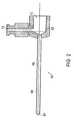
- FIG. 2is a cross-sectional view of cannula
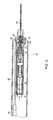
- FIG. 3is a cross-sectional view of a trocar within a cannula
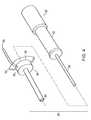
- FIG. 4is a perspective view of the miniature endoscope
- FIG. 5is a sectional view of the miniature endoscope with a cannula overlying the disposable sheath;
- FIG. 6Ais a sectional view of the disposable sheath/illuminator unit
- FIG. 6Bis an enlarged sectional view of the distal end to the disposable sheath
- FIG. 7Ais a sectional view of the proximal end of the disposable sheath/illumination unit taken along line 7 A- 7 A of FIG. 6A ;
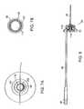
- FIG. 7Bis a front view of the distal end of the disposable sheath taken along the line 7 B- 7 B of FIG. 6A and FIG. 6B ;
- FIG. 8is a side view of the disposable sheath/illumination unit showing the illumination pigtail
- FIG. 9is a sectional view of an imaging unit of the miniature endoscope.
- FIG. 10Ais an enlarged view of the distal end of the imaging unit as indicated by the portion defined 10 A in FIG. 9 ;
- FIG. 10Bis a front view of the distal end of the imaging unit taken along the line 10 B- 10 B of FIG. 10A ;
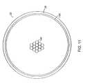
- FIG. 11is a schematic of an enlarged partial sectional view of the imaging unit taken along the line 11 - 11 of FIG. 10A ;
- FIG. 12is an enlarged view of the distal lens system
- FIG. 13is a graph of the sine of the maximum ray angle versus normalized image height for different lens systems for the distal end of the endoscope
- FIG. 14is an enlarged view of another embodiment of a distal lens system
- FIG. 15is a sectional view of another embodiment of an endoscope
- FIG. 16Ais a sectional view of the endoscope taken along line 16 A- 16 A of FIG. 15 ;
- FIG. 16Bis a sectional view of the endoscope taken along line 16 B- 16 B of FIG. 15 ;
- FIG. 16Cis an enlarged sectional view of the imaging unit as indicated by the portion defined by 10 C in FIG. 16B ;
- FIG. 17Ais a sectional view of another embodiment of an endoscope
- FIG. 17Bis a sectional view of the endoscope taken along the line 17 B- 17 B of FIG. 17A ;
- FIG. 18is a side view of a two-part disposable sheath/illuminator unit
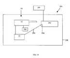
- FIG. 19is a schematic of a control unit for a preferred embodiment of the invention.
- FIG. 20illustrates a preferred method of using the invention
- FIG. 21illustrates a preferred embodiment of a portable endoscopic system in accordance with the invention
- FIG. 1An embodiment of the invention is illustrated in FIG. 1 that shows a miniature endoscope 20 .
- the endoscope 20has an imaging unit 22 and a sheath/illuminator unit 24 .
- the endoscope 20has an image transmission path such as a plurality of optical fibers 26 , as best seen at fibers 146 in FIGS. 11 and 12 , in an elongated tube 28 of a rod tip 29 used to view objects to be examined.
- the optical fibers 26are optically coupled to an imaging device 30 , such as a charged coupled device as seen in FIG. 9 , or other pixilated flat panel sensor, in a handle 32 .
- an imaging device 30such as a charged coupled device as seen in FIG. 9 , or other pixilated flat panel sensor
- a disposable sheath 34 of the sheath/illuminator unit 24overlies the elongated tube 28 of the rod tip 29 , which contains the optical fibers 26 .
- the disposable sheath 34has at the proximal end a base 35 with a mounting mechanism 36 for securing to the handle 32 .
- the disposable sheath 34 of the sheath/illuminator unit 24has a plurality of optical fibers for transmitting light to the distal end of the disposable sheath 34 and the distal probe 29 .
- the distal end of the disposable sheath/illuminator unit 24has a connection 38 to connect to a light source 40 .
- the handle 32can house a power input 41 , used to provide power to the endoscope 20 . It is recognized that the light source 40 and/or power source can be mounted within the handle 32 .
- the handle 32can also house an image output 42 .
- the image output 42provides a connection between an imaging device in the imaging unit 22 of the endoscope 20 and an electronic storage and/or display device.
- the storage deviceis a computer 44 , which is connected to a monitor 46 .
- a control unit 250is described in greater detail with respect to FIG. 19 .
- the sheath/illuminator unit 24has the disposable sheath 34 that is a sleeve assembly 52 that is carried by the base 35 secured to the imaging unit 22 that overlies the elongated tube 28 to create a sterilized barrier.
- the sheath/illumination unit 24has a sterilized drape 52 which is mounted to the base 35 of the sheath/illuminator unit 24 and is positioned to overlie the remaining portion of the imaging unit 22 to provide a sterile environment.
- the endoscope 20needs to be positioned in the body to view the desired location.
- One such methodis to insert a cannula 60 into the body and thread the endoscope 20 through the cannula 60 .
- One method of inserting the cannula 60 into the body and then inserting the endoscope 20 into a body using the cannula 60is described below.
- a cannula 60such as seen in FIG. 2 , is first inserted into a site within a body.
- the cannula 60has a base 62 and a tube 64 .
- the tube 64has a shaft 66 which extends from the distal end 68 to a void 70 in the base 62 .
- the tube 64is made of a flexible material such as plastic or thin wall stainless steel.
- the cannula 60has a luer 72 for insertion of medications or fluids or for attachment to a suction device.
- a trocar 76For insertion of the cannula 60 into the body, a trocar 76 , as seen in FIG. 3 , is inserted into cannula 60 with a rigid shaft 78 of the trocar 76 received within the shaft 66 of the cannula 60 .
- the rigid shaft 78 of the trocar 76extends slightly beyond the distal end of the tube 64 of the cannula 60 and has a stylet 80 to cut into the tissue at the surgical site if necessary.
- the cannula 60 and trocar 76are of a relative minimal cost and can be reused after sterilization or disposed of after use, because of several components in the endoscope 20 such as components in the imaging unit 22 , it is not desirous to dispose of the entire endoscope 20 .
- the endoscope 20uses a disposable sleeve or sheath 34 to aid in maintaining a sterile environment and reduce or eliminate the sterilization requirements prior to reuse.
- the endoscope 20has the reusable imaging unit 22 and the disposable sheath/illuminator unit 24 .
- the disposable sheath/illuminator unit 24has a elongated tube for overlying and encircling the elongated tube 28 of the imaging unit 22 .
- the elongated tube of the sheath/illuminator unit 24has a sealed distal end 84 and several embodiments includes fiber optics for transmitting the illumination from a external light source 40 , such as seen in FIG. 1 , to the distal end 84 .
- a base 35At the proximal end of the sheath/illuminator unit 24 is a base 35 with a mounting mechanism 36 for securing to the imaging unit 22 of the endoscope 20 .
- An optical pigtail 88projects from the base 35 for connecting to the light source 40 .
- the sheath/illuminator unit 24has a the drape 52 which is mounted to the base 35 and is extended over the handle 32 of the imaging unit 22 .
- the handle 32 of the imaging unit 22contains optics and the imaging device 32 to receive the image transmitted through the optical fibers 26 located in the elongated tube 28 of the imaging unit 22 as described in further detail below with respect to FIGS. 9-11 .
- FIG. 5is a sectional view of the miniature endoscope 20 including the reusable imaging unit 22 with imaging an optical fiber 26 and the disposable sheath/illuminator unit 24 .
- the cannula 60is shown overlying the disposable sheath 34 of the sheath/illuminator unit 24 , which overlies the probe 29 of the imaging unit 22 .
- the reusable imaging unit 22 of the endoscope 20is encircled by the disposable sterile sheath/illuminator unit 24 .
- the disposable/sheath illuminator unit 24has the disposable sheath 34 that is sealed at the distal end 84 and encircles and surrounds the elongated tube 28 carrying the optical fibers 26 of the imaging unit 22 .
- the mounting mechanism 36 on the base 35 of the sheath/illuminator unit 24is secured to a mounting mechanism 92 on the imaging unit 22 .
- the disposable sheath/illuminator unit 24has the drape 52 which surrounds the handle of the imaging unit 22 .
- the sheath/illuminator unit 24has the illumination pigtail connecting to a light source 40 as seen in FIG. 1 .
- the illumination pigtail 88is optically coupled to the optical fibers in the sheath as explained in further detail below.
- the sheath unit 24has the disposable sheath 34 with an elongated outer sheath 98 which extends from the base 35 to the distal end 84 .
- the illuminator pigtail 88extends from the base and is optically coupled to illumination fibers within the sheath 34 as seen in FIG. 7A .
- the drape 52is carried by the base 35 of the sheath/illuminator unit 24 for overlying the handle 35 of the imaging unit 22 when the two units 22 and 24 are combined.
- FIG. 6Bis an enlarged view of the distal end 84 of the disposable sheath 34 of the sheath/illuminator unit 24 .
- the disposable sheath 34has the outer sheath 98 which extends from within the base 35 , as seen in FIG. 6A , and serves as protective covering and a sterile barrier for the sheath unit 24 .
- Spaced and collinear with the outer sheath 98is an inner tube 100 of the disposable sheath 34 .
- the inner tube 100defines a cylindrical void on space 102 for receiving the elongated tube 28 of the probe 29 of the imaging unit 22 .
- the inner tube 100likewise from the distal end 84 of the disposable sheath 34 to the base 35 of the sheath/illuminator unit 22 .
- the inner tube 100extends further than the outer sheath 98 to create a channel 106 to receive a plurality of illumination fibers 108 as best seen in FIGS. 6A and 7A .
- a window 110which is secured to the inner tube 100 to make a sterile 84 barrier between the airspace 102 for receiving the elongated tube 28 of the image unit 22 and the outer portion of the sheath/illuminator unit 24 which is in contact with the body.
- the outer sheath 98 of the disposable sheath 34 of the sheath/illuminator unit 24is made of a stainless steel material and has an outer diameter of about 0.038 inches.
- the inner tube 100is likewise made of a stainless steel material.
- the illumination fibers 108are made of a glass or plastic fiber. Depending on the size of the device, the maximum number of illumination fibers 108 used to fill channel 106 .
- the disposable sheath 34extends 2.246 inches from the base 35 of the sheath/illuminator unit 24 .
- FIG. 7Ais a sectional view through the base 35 of the disposable sheath 24 .
- the outer sheath 98is shown in the lower half of FIG. 7A and terminates prior to the portion sectioned in the upper half of FIG. 7A .
- the inner tube 100which defines the airspace 102 to receive the elongated tube 28 of the imaging unit 22 extends to a receiving chamber 114 as seen in FIG. 6A and therefore is shown in both the upper and lower portions of FIG. 7A .
- the lightis transmitted from the illumination pigtail 88 through fibers 108 , as seen in FIG. 6A , to a transmission unit 118 as seen in the upper half of FIG. 7A which abuts the illumination fibers 108 located between the outer sheath 98 and the inner tube 100 of the disposable sheath 34 of the sheath/illuminator unit 24 .
- FIG. 7Bshows the distal end 84 of the disposable sheath/illumination unit 24 .
- the window 110overlies and seals the airspace 102 that receives the imaging unit 22 and is encircled by the inner tube 100 .
- Interposed between the outer sheath 98 and the inner tube 100is the plurality of illumination fibers 108 .
- the distal end of the illumination fibers 108are not protected and exposed to the body.
- FIG. 8is similar to FIG. 6A in that it shows the disposable sheath/illumination unit 24 . In addition, FIG. 8 shows the entire illumination pigtail which is broken away in FIG. 6A .
- the illumination pigtail 88has a connection 38 for connecting to a connector on the light source 40 .
- the illumination pigtail 88has a plurality of optical fibers which run from the connection 38 to the fibers 108 which transmit the light received from the light source 40 to the transmission unit 118 shown in FIG. 7A and exit at 84 .
- the imaging unit 22has the probe 29 with the elongated tube 28 that extends from the handle 32 .
- the imaging deviceAt the proximal end of the handle 32 , is the imaging device.
- a charged coupled device (CCD) 30 Bwhich converts the optical image into an electrical image is carried in the detachable housing 120 A of the handle 32 .
- a plurality of lenses 122 AInterposed between the optical fiber or fibers 26 which extend in the elongated tube 28 and the CCD 30 B is a plurality of lenses 122 A for projecting the image of the proximal end 124 of the optical fiber or fibers 26 to the CCD 30 B.
- the glass window 122 Bis attached to housing 120 B and provides a seal to the scope. It also protects the lenses from contamination.
- the imaging unit 22enlarges the image from the end of the fiber optic 26 and couples it to the charged coupled device 30 B.
- the charged coupled deviceis connected to a electronic storage and/or display device such as a computer 44 which is connected to a monitor 46 as seen in FIG. 1 .
- the handle 32 of the imaging unit 22has a mounting mechanism 128 for coupling with the mounting mechanisms 36 of the sheath illuminator unit 24 .
- the mounting mechanism 128has slots 130 for receiving pins located on the mounting mechanisms 36 .
- the mounting mechanism 128has a projection 134 , from which the probe 29 projects, that is received by the receiving chamber 114 of the sheath/illuminator unit 24 as seen in FIG. 6A .
- FIG. 10AAn enlarged view of the distal end of the imaging unit 22 is shown in FIG. 10A .
- the rod tip 29 of the imaging unit 22has the elongated tube 28 that extends from the distal end 126 to the housing 120 of the handle 32 .
- a tube 138which extends a slight distance from the distal end 126 and just a slight distance beyond the ends of the optical or image fibers 26 .
- the tube 138is commonly referred to as the long tube in that a shorter and smaller diameter tube 140 which is collinear with the long tube 138 is received within the long tube 138 and extends a lens system 142 at the distal end 126 .
- the elongated or outer tube 128 , long tube 138 and small tube 140are mounted so that their distal ends are flush and are secured by an adhesive such as a modicalgrade epoxy.
- an adhesivesuch as a modicalgrade epoxy.
- the lens system 142At the end of the elongated tube 28 of the imaging unit 22 is the lens system 142 that is described in further detail below.
- the elongated tube 28 of the imaging unit 22is received within the disposable sheath/illumination unit 24 and therefore does not need to be sterilized prior to the first use.
- FIG. 10Bis an end-view of the distal end 126 of the imaging unit 22 .
- the lens system 142 , the small tube 140 , the long tube 138 and the outer or elongated tube 28are shown and are all collinear.
- FIG. 11a sectional view of the imaging unit 22 of the endoscope 20 is shown.
- the probe 29 of the imaging unit 22has a plurality of fibers 146 for transmitting the image from the distal end 126 of the rod tip 29 to the handle 32 .
- Encircling the fiber 146 at the distal end of the rod tip 29is the long tube 138 for holding the fibers 146 of the image fibers 26 in position.
- the outer or elongated tube 28encircles the long tube 138 and protects the fibers 146 of the image fibers 26 from their beginning near the distal end 126 of the rod tip 29 to the other end within the handle 32 .
- the fibersare in a disorder pack method.
- This disorder pack methodlimits transmission of images/light from one lens 142 to another as the image fiber bundle 26 extends from near the distal end 126 of the imaging unit 22 towards the proximal end of the fibers located within the handle 32 .
- the disorder packing of fibersis achieved by varying the doping of the fibers, which is the area to be examined.
- FIG. 12a sectional view of the distal end of the rod tip 29 of the imaging unit 22 within the disposable sheath 34 of the sheath/illuminating unit 24 is shown.
- the disposable sheath 34has the outer sheath 98 collinear with the inner tube 100 .
- the plurality of illumination fibers 108Interposed between the outer sheath 98 and the inner tube 100 is the plurality of illumination fibers 108 as best seen in FIG. 7B for illumination.
- the windowAt the distal end of the disposable sheath is the window that is secured, such as by cementing, to create a boundary to the air space or inner channel 102 that receives the rod tip 29 of the imaging unit 22 .
- the imaging unit 22has the elongated or outer tube 28 that extends from the distal end 126 to within the handle 32 as shown in FIG. 9 .
- a larger longer sleeve, referred to as the long tube 138encircles the tube 140 and the beginning of the fibers 146 of the image fibers 26 .
- the distal lens system 142 as shown in FIG. 12is an achromatic lens system having a pair of lenses 150 and 152 and an aperture stop 154 .
- the lenses 150 and 152each have a convex surface 156 that faces each other.
- the second lens 152closer to the distal end 126 , has a planar surface 158 which abuts the optical aperture stop 154 .
- the aperture stop 154 and the lenses 150 and 152are designed so that the sine of the maximum ray angle approaches the fibers at N.A. (numerical aperture).
- the ray tracings 160 in FIG. 12illustrate the projection of an image off the page to the right at the proper focal length and how this image is translated through the aperture stop 154 and through the lenses 152 and 150 to the plurality of fibers 146 in the image fibers 26 .
- the lens systemis non-telecentric.
- FIG. 13a graph of the sign of the maximum ray angle versus the normalized image height for three different lens systems including a prior art lens system is shown.
- the graph in FIG. 13shows a line for the maximum sign of a ray angle for a 50 degree lens system and a second line for a maximum sign of ray angle of a 70 degree lens system.
- the maximum signis approximately 0.32. Therefore, the N.A. (numerical aperture) of the fiber is approximately the same.
- the 50 degree field of view systemhas an sign of a maximum ray angle of approximately 0.25. Therefore, the fibers have this numerical aperture.
- the systemcan provide a field of view at any selected level from 30-80 degrees, for example.
- the endoscope 20has 10,000 fiber elements.
- each fiber element 146has a diameter of 4.4 microns.
- the overall diameter of the fiber 26is 0.46 mounting mechanism.
- the elongated or outer tube 28 of the imaging unitis made from stainless steel. It is recognized, that the scope can be formed in many sizes, the following table is merely an illustration of various intervening size scopes.
- FIG. 14shown an alternative embodiment of the rod tip 29 of the imaging unit 22 of the endoscope 20 with a grin lens 168 .
- the grin lens 168 as shown in FIG. 14is a single element gradient index lens.
- the rod tip 29 of the image unit 22 as shown in FIG. 14has an elongated or outer tube 28 that extends from the distal end 126 to the handle 32 , not shown in FIG. 14 .
- a tube 138extends a slight distance from the distal end 126 .
- This tube 138is commonly referred to as the long tube, it extends just slightly beyond the ends of the optical image fibers 26 .
- the lens 170is a single lens there is no need for a small tube 140 for retaining the elements of a lens system.
- the grin lens 168in general does not provide as good of image quality as that of the acromat lens system 142 described above in that the image becomes less clear (i.e., blurry and distorted) towards the edge of the image.
- the color correctionchanges in intensity as a function of wavelength, is not as good as in the acromat lens system.
- the GRIN lens system 168maybe desirable in situations where cost is a higher factor than the overall image quality.
- the depth of fieldsmay be limited. While only 2 different degrees of freedom are shown, it is recognized that lens systems with other fields of view can be made.
- FIG. 15is a sectional view of alternative endoscope 170 .
- the illuminator pigtail 172is a part of the handle 174 of the imaging unit 176 and is therefore not part of a disposable sheath/illuminator unit 178 .
- An optical fiber bundle 180is used for transmitting the illumination light from the pigtail 172 to a handle interface 182 in the handle 184 where the light is transferred to a light interface 184 on the sheath/illuminator unit 178 to transmit light from the handle 184 to the disposable sheath 186 .
- FIG. 16Ais a sectional view showing the interface.
- FIG. 16Ais a sectional view of the base 188 of the disposable/sheath illuminator unit 178 .
- the upper portion of FIG. 16Ashows the drape 52 spaced from the base 188 .
- the base 188has a light interface 184 that receives light from the handle interface 182 carried on the handle 174 .
- the sheath/illuminator unit 178has one of the illumination fibers 190 replaced by a tube or channel 192 .
- the tube 192which is seen in FIGS. 15 and 16 A- 16 C is capable of receiving a laser fiber.
- the userpasses a laser fiber though the tube 190 from the proximal end of the illumination unit 178 in the base 188 as seen in FIG. 15 , to the distal end of the illumination unit so that the user while viewing the image through the imaging fibers and CCD can complete a process using the laser fiber.
- FIG. 16Ashows a cross-sectional view through the base 188 of the sheath/illuminator unit 178 shows the tube 192 extending through the base into the annular ring containing the illumination fibers 190 . Similar to that shown in FIG. 7A , FIG. 16A shows an inner tube 194 around which the illumination fibers 190 are located. The inner tube 194 defines an airspace through which the probe 29 of the imaging unit 176 of the endoscope 170 passes.
- FIG. 16Bis a sectional view of the disposable sheath 186 showing an outer tube 196 of the disposable sheath 186 and circling the illumination fibers 190 and a signal hypotube 192 .
- the inner tube 194surrounds the airspace 102 which receives the probe 29 of the imaging unit 176 .
- FIG. 16Cis an enlarged view showing the hypertube 192 with its opening to receive the laser fiber in the annular ray containing the illumination fibers 190 between the inner tube 194 and outer sheath 196 .
- FIGS. 15-16Cdo not show a cannula 60 , it is recognized in most uses of the endoscope 20 or 170 , a cannula 60 can be used for extra protection of the endoscope 20 or 170 .
- FIG. 17Aa sectional view of an alternative endoscope 200 is shown.
- the endoscope 200has an imaging unit 202 and a sheath unit 204 .
- the sheath 204 that is disposabledoes not include any part of the illumination unit.
- the illumination source 40is connected to the handle 206 of the imaging unit 202 by an illumination pigtail 208 similar to that shown in FIG. 15 . But in contrast, there is no coupling such that that the light is transmitted to the disposable sheath 204 . Rather, as seen in FIG. 17A , the illuminator pigtail 208 is a part of the handle 206 of the imaging unit 202 .
- An optical fiber 210is used for transmitting the illumination light from the pigtail 208 to an interface 212 in the handle 206 .
- the interface 212is located within the handle 206 and transfer the light to an annular ring 214 of a plurality of illumination fiber 216 .
- the probe 218has an outer tube 220 and an inner tube 222 . Interposed between the tubes 220 and 222 is the annular space for receiving the plurality of illumination fiber 216 . Located in the inner tube 222 , which is similar to the elongated tube 28 in the first embodiment, is the image fiber bundle 26 . The fiber bundle 26 is spaced from the inner tube 222 . A long tube 224 , which extends for a slight distance from the distal end 126 to just beyond the ends of the image fiber bundle 26 , is interposed between the fibers 26 and the inner tube 222 .
- the sheath 204has a single outer layer 226 .
- a window curved to avoid retroreflectionis secured to the distal end of the single outer layer 226 .
- a two piece disposable sheath/illuminator unit 230is shown.
- the endoscopehas a first unit 232 of the two piece disposable sheath/illumination unit 230 , a mounting and cover unit 232 , that is mounted to the handle 32 of the imaging unit 22 .
- the mounting and cover unit 232has a drape 52 that extends over the handle 32 of the imaging unit 22 and the illumination pigtail 88 when used.
- the drape 52is retained on a disposable sleeve 234 to hold the drape 52 until positioned over the handle 32 .
- the second unit 236 of the disposable sheath/illumination unit 230 , a disposable sheath 236contains the elongated tube that covers the probe 29 .
- This second unit 236has a mounting mechanism 238 to secure to the first unit 232 . It is therefore possible to remove the disposable sheath, the second unit, 236 and replace it with a new one while keeping the drape 52 that is mounted to the mounting and cover unit 232 over the handle.
- FIG. 19is a schematic of a control unit 250 for the endoscope.
- This control unit 250has a power source output 252 , an input 254 for the image from the CCD and a light source 256 .
- the unithas a recording device 258 such as a CD writer to create a storable medium to retain data such as a baseline for the patient.
- the endoscopeis used as shown generally in the process sequence 270 of FIG. 20 .
- the patientcomes to the user/physician's office.
- the physician or technicianuses a double gloved technique where two sterilized gloves are placed on each of the physician's hands.
- the physiciantakes the handle/illuminator unit which is not sterilized in one hand and secure the sterilized sheath/illuminator unit with the other hand.
- the physicianthen takes the lighting cord and secure the light cord to the pigtail on the disposable sheath/illuminator unit.
- the power and image outputare likewise connected to the control unit.
- the drape portion of the sheath assemblyis extended 272 over the handle and down the cords to such a length to provide a sterile field.
- the physiciantakes off the first pair of gloves and is ready to begin the procedure.
- the cannula with the trocaris inserted into the body by a standard technique of probing with the physician's hand.
- the trocaris removed 274 and the tip of the endoscope is placed into the cannula.
- the endoscopeis secured to the cannula using a screw or other attachment mechanism.
- the systemis actuated 276 and video recording is initiated so that the physician is able to move the cannula in and out and around to position the probe for viewing of the desired site or a monitor.
- the physiciancan perform a procedure 278 at the site using other instruments such as a laser scalpel or cautery tool, or electrosurgical tool and/or the operative channel in the probe or sheath assembly.
- the entire examination or operative procedurecan be recorded 280 on a video disk or other memory device.
- the procedureis concluded and the sheath assembly can be disposed 282 of and another sterile sheath assembly can be attached 284 to the probe for another procedure.
- a preferred embodimentprovides multi spectral imaging capability.
- This embodimentincludes the use of a light source and a detector to provide images over the wavelength range of 700 nm-1200 nm. This allows the user to see through blood to observe tissue.
- UVultraviolet
- Another embodimentuses the ultraviolet (UV) region of the electromagnetic spectrum (10 nm-380 nm) to be able to treat tissue.
- Ultraviolet lightin the range of 325-250 nm can pull together and cauterize.
- Lasers or conventional broadband light sourcescan be used to provide light to the illumination system.
- the imaging fiber bindlecan also be used for illumination with a beam splitter in the handle to couple light from one or more sources individually or simultaneously to the fiber bundle.
- Embodiments of the inventioncan be employed in office-based settings for performing diagnostic imaging of interior surfaces of a body.
- Office-basedrefers to locations other than essentially sterile environments such as, by way of example, hospital operating rooms, hospital procedure rooms, rooms proximate to sterilization means such as autoclaves, and the like. Examples of office locations are, but are not limited to, examination rooms at a physician's office, training rooms adjacent to locker rooms in sporting complexes, ambulances, residences, field hospitals, hospital corridors, examination rooms, emergency rooms, office buildings, stores, and the like.
- the miniature endoscope 20operates as a fluidless system, although fluid can be used if desired.
- a fluidless systemrefers to the fact that no liquid media, irrigation or distention fluid (e.g., saline solution) has to be injected into a patient's body in the vicinity of the target area, i.e. the area that will be viewed using the invention.
- the miniature endoscopecan simply be inserted through a patient's skin, and used to view a target area without requiring additional instruments, injection means, consumable substances and without generating excess hazardous waste, other than the disposable portion, such as would be generated if irrigation fluids were injected into and removed from the target area.
- the disposable portion 20may comprise a disposable needle covering employing a transparent window in its distal end.
- the transparent windowprevents fluids from a patient's body from coming into contact with non-disposable portions (e.g., 32 ) of the system.
- Nondisposable portions operating in conjunction with the disposable portion 20may include a thin shaft which slides inside the introducer and contains a fiber optic illumination system for conducting images of the target area to a miniature camera located in a handle 32 .
- the fiber optic illumination systemmay comprise a protective window and high resolution fiber optics and lens transmission means for conveying images to the camera.
- the disposable portionmay also include a slide port for introduction of surgical instruments or for evacuation of fluids by suction or for introduction of medications to the target area.
- FIG. 21illustrates exemplary embodiments of a portable endoscopic system 291 comprising, among other things, miniature endoscope 20 , handle 32 , imaging unit 22 , cable 290 and laptop 292 .
- the endoscopic unit and imaging unit 22are connected directly to laptop 292 by way of cable 290 .
- imaging unit 22may output a video signal that is sent to a video in jack on laptop 292 .
- Laptop 292is then used to enter patient information, session details, and is used to display real-time image data as the procedure is carried out.
- PCMCIApersonal computer memory card international association
- PCMCIA cardmay be an industry standard card as known in the art, or it may be specially adapted for use with the miniature endoscope.
- a specially adapted PCMCIA cardmay include hardware for receiving and processing video signals received from the imaging unit.
- the output of PCMCIA card 294may be an industry standard data format for conveying processed image data to a display associated with laptop.
- a portable endoscopic system 291that includes imaging unit or an interface box 32 and an interface box cable 290 for conveying data to laptop 292 .
- Interface boxmay include more sophisticated imaging, image processing, and data communication hardware and/or software than can be employed in PCMCIA card 294 or directly inside laptop 292 .
- the interface box 296may be configured to perform real-time image enhancement on data received through the distal end of miniature endoscope 20 .
- Image enhancementmay be used to produce images suitable for performing diagnostics while making use of less costly components in miniature endoscope 20 .
- a GRIN lensmay be employed in miniature endoscope 20 to provide image data to interface box.
- Interface boxmay employ image processing algorithms for enhancing the image quality produced by the edges of GRIN lenses.
- Interface boxmay then convey image data to laptop 292 in an industry standard format by way of cable.
- the systemcan also include mounting on a cart 298 for transport, as display 295 and a light source system 296 .
- the systemcan include a standard lamp for visible light imaging as well as infrared or ultraviolet light sources for imaging or treatment.
- a generalized architecturecan be used including a central processing unit (CPU), which is typically comprised of a microprocessor associated with random access memory (RAM) and read-only memory (ROM). Often, CPU is also provided with cache memory and programmable FlashROM.
- the interface between the microprocessor and the various types of CPU memoryis often referred to as a local bus, but also may be a more generic or industry standard bus.
- CPUprocesses and interprets machine-readable, or function-executable, instructions associated with an operating system, user-developed applications, diagnostic tools, patient data hospital servers, health provider computers, and computers associated with remote experts.
- GUIgraphical user interface
- HDDhard-disk drives
- CD-Rcompact disc drives
- CD-RWcompact disc drives
- DVD-RDVD-R
- proprietary disk and tape drivese.g., Iomega ZipTM and JazTM, etc.
- storage drivesmay be accessible over a computer network such as network-based storage system.
- the RAMis capable of storing machine-readable instructions and information necessary to operate software applications for processing and displaying image data received from miniature endoscope.
- a personal computer, laptop, or belt-wearable computeris often provided with a high speed serial port (RS-232, RS-422, etc.), an enhanced parallel port (EPP), and one or more universal serial bus (USB) ports.
- the computing platformmay also be provided with a local area network (LAN) interface, such as an Ethernet card, and other high-speed interfaces such as the High Performance Serial Bus IEEE-1394.
- LANlocal area network
- Computing platformssuch as wireless telephones and wireless networked PDA's may also be provided with a radio frequency (RF) interface with antenna, as well.
- RFradio frequency
- the computing platformmay be provided with an infrared data arrangement (IrDA) interface, too.
- IrDAinfrared data arrangement
- ISAIndustry Standard Architecture
- EISAEnhanced Industry Standard Architecture
- PCIPeripheral Component Interconnect
- PCMCIAPersonal Computer Memory Card International Association
- proprietary interface slotsfor the addition of other hardware, such as sound cards, memory boards, and graphics accelerators.
- many unitssuch as laptop computers and PDA's, are provided with one or more external expansion slots allowing the user the ability to easily install and remove hardware expansion devices, such as PCMCIA cards, SmartMedia cards, and various proprietary modules such as removable hard drives, CD drives, and floppy drives.
- hardware expansion devicessuch as PCMCIA cards, SmartMedia cards, and various proprietary modules such as removable hard drives, CD drives, and floppy drives.
- the storage drives, communication interfaces, internal expansion slots and external expansion slotsare interconnected with the CPU via a standard or industry open bus architecture, such as ISA, EISA, or PCI.
- a computing platformis usually provided with one or more user input devices, such as a keyboard or a keypad, and mouse or pointer device, and/or a touch-screen display.
- user input devicessuch as a keyboard or a keypad, and mouse or pointer device, and/or a touch-screen display.
- a full size keyboardis often provided along with a mouse or pointer device, such as a track ball or TrackPointTM.
- a simple keypadmay be provided with one or more function-specific keys.
- a touch-screenis usually provided, often with handwriting recognition capabilities, and in the case of a laptop, a small keyboard and touch-sensitive display may be provided.
- a microphonesuch as the microphone of a web-enabled wireless telephone or the microphone of a personal computer, is supplied with the computing platform.
- This microphonemay be used for entering user choices, such as voice navigation of web sites, user menus associated with operating miniature endoscope 20 , conveying data to remote locations, or auto-dialing telephone numbers.
- Voice recognition capabilitiesnormally in the form of software may be employed for facilitating speech based interaction with the computer.
- Many computing platformsare also equipped with a camera device, such as a still digital camera or full motion video digital camera which can be used for facilitating collaboration between the person performing the endoscopic procedure and a remote expert that may be guiding the procedure and interpreting results in essentially real-time by way of a networked display device.
- a camera devicesuch as a still digital camera or full motion video digital camera which can be used for facilitating collaboration between the person performing the endoscopic procedure and a remote expert that may be guiding the procedure and interpreting results in essentially real-time by way of a networked display device.
- the displaymay take many forms, including a Cathode Ray Tube (CRT), a Thin Flat Transistor (TFT) array, a simple set of light emitting diodes (LED), liquid crystal display (LCD) indicators, a heads-up (i.e. hands free) display, or a projection display.
- CTRCathode Ray Tube
- TFTThin Flat Transistor
- LEDsimple set of light emitting diodes
- LCDliquid crystal display
- heads-upi.e. hands free
- One or more speakers and/or annunciatorsare often associated with computing platforms, too.
- the speakersmay be used to reproduce audio instructions.
- Annuciatorsmay take the form of simple beep emitters or buzzers, commonly found on certain devices such as PDAs and PIMs. Annunciators may be used to alert the operator of system that an error has occurred.
- These user input and output devicesmay be directly interconnected to the CPU via a proprietary bus structure and/or interfaces, or they may be interconnected through one or more industry open buses such as ISA, EISA, PCI, etc.
- the computing platformis also provided with one or more software and firmware programs to implement the desired functionality of the computing platforms.
- OSoperating system
- portable or device-independent programsmay be provided, which must be interpreted by an OS-native platform-specific interpreter, such as JavaTM scripts and programs.
- computing platformsare also provided with a form of web browser or micro-browser, which may also include one or more extensions to the browser such as browser plug-ins and configured to facilitate transmission and reception of image data over network.
- the computing deviceis often provided with an operating system, such as Microsoft WindowsTM, UNIX®, IBM OS/2TM, or AIX®, LINUX, MAC OSTM, Sun SolarisTM, or other platform specific operating systems.
- an operating systemsuch as Microsoft WindowsTM, UNIX®, IBM OS/2TM, or AIX®, LINUX, MAC OSTM, Sun SolarisTM, or other platform specific operating systems.
- Smaller devicessuch as PDA's and wireless telephones may be equipped with other forms of operating systems such as real-time operating systems (RTOS) or Palm Computing's PalmOSTM.
- RTOSreal-time operating systems
- Palm Computing's PalmOSTMPalm Computing's PalmOSTM.
- BIOSbasic input and output functions
- hardware device drivers 356are often provided to allow the operating system and programs to interface to and control the specific hardware functions provided with the computing platform.
- one or more embedded firmware programs 358are commonly provided with many computing platforms, which are executed by onboard or “embedded” microprocessors as part of the peripheral device, such as a microcontroller or a hard drive, a communication processor, network interface card, or sound or graphics card.
- An exemplary systemuses portable system operating in conjunction with a network.
- a doctor's officecontaining portable system, a network, a health insurance provider having data storage associated therewith, a hospital server having data storage, a remote expert computer and a network-based storage system.
- Networkmay be any type of network running any kind of network protocol.
- networkmay be an intranet such as a local area network (LAN) operating within a corporate location or university campus, a metropolitan area network (MAN) operating within a geographic region such as a city and its surrounding suburbs, or a wide area network (WAN) such as the world wide web.
- LANlocal area network
- MANmetropolitan area network
- WANwide area network
- networkmay run any type of networking protocol such as, for example, transmission control protocol and Internet protocol (TCP/IP), asynchronous transfer mode (ATM), synchronous optical network (Sonet), frame relay, integrated services digital network (ISDN), open shortest path first (OSPF), etc.
- Networkmay employ a plurality of links for coupling network elements and locations. Links may be comprised of hardwired links and/or wireless links. Examples of hardwired links are, but are not limited to, coaxial cable, twisted pair cable, optical fibers, etc.; and examples of wireless links are, but are not limited to, radio frequency (RF) such as IEEE 802.11 based links, or free space optical links.
- Networkmay also comprise gateways and/or firewalls for providing access to network and for providing protection against undesirable network traffic such as denial-of-service attacks as well as network traffic containing malicious code such as computer worms and viruses.
- Data conveyed from portable system to networkmay be directed to a health insurance provider.
- the health insurance providermay archive received data on data storage by way of link for future use.
- Health insurance providermay employ its own experts, alone or in combination with automated analysis systems, to review data obtained during an endoscopic procedure using the invention.
- Portable systemmay also convey data to a hospital server.
- the hospital servermay further include data storage coupled thereto by link.
- Hospital servermay serve as a pooling resource for maintaining data associated with patients having an affiliation therewith.
- Data obtained using portable systemmay further be sent to a remote expert computer by way of network.
- a remote expertusing remote expert computer, may review image data post mortem or in quasi-real-time.
- the remote expertmay provide a second opinion prior to scheduling more invasive procedures or the remote expert may provide the primary diagnosis in situations where a skilled operator is performing the procedure with miniature endoscope 20 .
- disaster relief personnelmay be on scene at a remote location and performing a diagnostic procedure on a disaster victim.
- a remote expertmay be viewing image data received over a free space satellite network in real-time to direct the on-scene personnel with respect to the diagnostic procedure.
- the remote expertmay then direct an on-scene person to mark an insertion location on a victim/patient, to introduce the needle covering, to maneuver the endoscope 20 , and then may use real-time data to recommend accurate treatment for the victim without having to be on site.
- Data from portable systemmay further be conveyed to network-based storage system.
- Network-based storage systemmay serve as secure and redundant storage for image data resident on laptop.
- network-based storage systemmay serve to keep image data in a location that is more readily accessed for replay than if the data were kept solely on laptop.
- the system and other remote entitiesmay be communicated with using portable system without departing from the spirit of the invention.
- a preferred method for using the miniature endoscope 20 in conjunction with portable system to perform diagnostic proceduresIn which the transport by cart into an examination room or other site where the procedure will be performed. Then a camera is coupled to the viewing system. Next, an insertion site is prepared on a patient's body. Preparation of the insertion site may include, among other things, marking the site using a medically approved writing instrument, cleansing the area with an antiseptic solution, etc.
- a disposable needle coveringmay be coupled to the imaging and viewing system. As previously discussed herein, only disposable portions of miniature endoscope 20 contact the patient so no special sterilization processes need be applied on site. The needle covering of miniature endoscope 20 is then inserted into a target area of a patient.
- the imaging and viewing systemmay be activated. Image data is viewed and recorded using laptop during the diagnostic procedure.
- the needleis withdrawn from the target area. After needle withdrawal, the insertion location may be dressed using sutures, liquid adhesives approved for topical wound dressing, butterfly closures, or conventional small wound dressings such as gauze or bandages.
- Recorded image datacan be reviewed by the diagnostician and shown to the patient in the procedure room. After review, recorded data can be archived locally on laptop, on removable storage media, or by way of network-based storage system. In addition, image data long with alphanumeric and/or voice annotations may be sent to one or more remote locations using network. Then the portable system may be returned to its storage location, and the patient immediately discharged after the procedure, since no complex anesthesia was required.
- the portable systemmay be deployed in a distributed architecture where the user is located at a first geographic location, with a patient and the miniature endoscope comprising elements 20 , 21 and 22 while the laptop display is located a distance away and is coupled to the miniature endoscope by way of a wireless network.
- the inventionmay be deployed in a ruggedized configuration for use in battlefield triage and/or for responding to disasters in remote and rugged locations.
- the portable endoscopic systemmay be integrated into mechanized conveyances such as trains, ambulances, air planes, ships, vehicles, etc.
- images generated using the portable endoscopic systemmay be replayed and used for training purposes.
- the portable endoscopic systemmay comprise a belt-wearable computer having a short range high bandwidth link to handle for receiving image data.
- handlemay comprise a self-contained power source such as a rechargeable battery.
- This embodimentmay further utilize a heads-up display worn on a user's head. Such a configuration provides the user with maximum mobility and minimum weight.
- the belt-wearable embodimentmay further communicate with network by way of a wireless link.
- laptopcan be replaced with a customized processing device that can take on essentially any form factor and user interface configuration.
- a customized processing devicethat can take on essentially any form factor and user interface configuration.
- the customized processing devicemay gather image data and store it for later review or it may automatically transmit data to a remote location using a wireless RF or free space optical link.
Landscapes
- Health & Medical Sciences (AREA)
- Life Sciences & Earth Sciences (AREA)
- Physics & Mathematics (AREA)
- Surgery (AREA)
- Optics & Photonics (AREA)
- Biomedical Technology (AREA)
- Animal Behavior & Ethology (AREA)
- Veterinary Medicine (AREA)
- Public Health (AREA)
- Engineering & Computer Science (AREA)
- Biophysics (AREA)
- Heart & Thoracic Surgery (AREA)
- Medical Informatics (AREA)
- Molecular Biology (AREA)
- Pathology (AREA)
- General Health & Medical Sciences (AREA)
- Nuclear Medicine, Radiotherapy & Molecular Imaging (AREA)
- Radiology & Medical Imaging (AREA)
- Astronomy & Astrophysics (AREA)
- General Physics & Mathematics (AREA)
- Endoscopes (AREA)
- Instruments For Viewing The Inside Of Hollow Bodies (AREA)
Abstract
Description
| 3k | 10k | 30k | 50k | 100k | |
| Sheath/ | 1-4 mm | → | → | → | → |
| Illumination unit | |||||
| outer diameter | |||||
| Imaging Unit rod | 0.5-3.5 mm | → | → | → | → |
| tip outer | |||||
| diameter | |||||
| No. of fiber | 3,000 | 10,000 | 30,000 | 50,000 | 100,000 |
| elements | |||||
| Fiber image | 0.46 mm | 0.75 mm | |||
| diameter | |||||
| Fiber pixel size | 4.4 microns | 4.4 microns | 4.4 microns | ||
| (individual fiber) | |||||
| Lens Type | Achromatic or | Achromatic or | Achromatic | Achromatic | Achromatic |
| Selfoc Grin | Selfoc Grin | ||||
| Depth of Field | 3 mm-20 mm | → | → | → | |
| (DOF) | |||||
| Field of View | Dependent on | → | → | → | → |
| (FOV) | |||||
Claims (16)
Priority Applications (16)
| Application Number | Priority Date | Filing Date | Title |
|---|---|---|---|
| US11/075,827US8038602B2 (en) | 2001-10-19 | 2005-03-08 | Portable imaging system employing a miniature endoscope |
| CN2012104228959ACN102973237A (en) | 2005-03-08 | 2006-03-08 | Portable imaging system employing a miniature endoscope |
| JP2008500898AJP2008532641A (en) | 2005-03-08 | 2006-03-08 | Portable imaging system using ultra-small endoscope |
| PCT/US2006/008342WO2006096797A2 (en) | 2005-03-08 | 2006-03-08 | Portable imaging system employing a miniature endoscope |
| EP20120161806EP2502551A1 (en) | 2005-03-08 | 2006-03-08 | Portable imaging system employing a minature endoscope |
| CN2006800105191ACN101208037B (en) | 2005-03-08 | 2006-03-08 | Portable Imaging System Using a Miniature Endoscope |
| CA002600443ACA2600443A1 (en) | 2005-03-08 | 2006-03-08 | Portable imaging system employing a miniature endoscope |
| EP06737509AEP1855580A4 (en) | 2005-03-08 | 2006-03-08 | Portable imaging system employing a miniature endoscope |
| US11/512,715US20070167681A1 (en) | 2001-10-19 | 2006-08-30 | Portable imaging system employing a miniature endoscope |
| US11/788,747US10595710B2 (en) | 2001-10-19 | 2007-04-20 | Portable imaging system employing a miniature endoscope |
| US12/439,116US11484189B2 (en) | 2001-10-19 | 2007-08-30 | Portable imaging system employing a miniature endoscope |
| JP2013190212AJP2014036868A (en) | 2005-03-08 | 2013-09-13 | Portable imaging system using ultraminiature endoscope |
| JP2015215533AJP2016052533A (en) | 2005-03-08 | 2015-11-02 | Portable imaging system using ultra compact endoscope |
| JP2017213777AJP2018038847A (en) | 2005-03-08 | 2017-11-06 | Portable imaging system employing miniature endoscope |
| JP2019168222AJP2020022761A (en) | 2005-03-08 | 2019-09-17 | Portable imaging system using ultracompact endoscope |
| US16/824,461US20210007585A1 (en) | 2005-03-08 | 2020-03-19 | Portable imaging system employing a miniature endoscope |
Applications Claiming Priority (2)
| Application Number | Priority Date | Filing Date | Title |
|---|---|---|---|
| US10/042,126US6863651B2 (en) | 2001-10-19 | 2001-10-19 | Miniature endoscope with imaging fiber system |
| US11/075,827US8038602B2 (en) | 2001-10-19 | 2005-03-08 | Portable imaging system employing a miniature endoscope |
Related Parent Applications (1)
| Application Number | Title | Priority Date | Filing Date |
|---|---|---|---|
| US10/042,126Continuation-In-PartUS6863651B2 (en) | 2001-10-19 | 2001-10-19 | Miniature endoscope with imaging fiber system |
Related Child Applications (1)
| Application Number | Title | Priority Date | Filing Date |
|---|---|---|---|
| PCT/US2006/008342Continuation-In-PartWO2006096797A2 (en) | 2001-10-19 | 2006-03-08 | Portable imaging system employing a miniature endoscope |
Publications (2)
| Publication Number | Publication Date |
|---|---|
| US20050283048A1 US20050283048A1 (en) | 2005-12-22 |
| US8038602B2true US8038602B2 (en) | 2011-10-18 |
Family
ID=36954019
Family Applications (1)
| Application Number | Title | Priority Date | Filing Date |
|---|---|---|---|
| US11/075,827Expired - Fee RelatedUS8038602B2 (en) | 2001-10-19 | 2005-03-08 | Portable imaging system employing a miniature endoscope |
Country Status (6)
| Country | Link |
|---|---|
| US (1) | US8038602B2 (en) |
| EP (2) | EP2502551A1 (en) |
| JP (5) | JP2008532641A (en) |
| CN (2) | CN102973237A (en) |
| CA (1) | CA2600443A1 (en) |
| WO (1) | WO2006096797A2 (en) |
Cited By (24)
| Publication number | Priority date | Publication date | Assignee | Title |
|---|---|---|---|---|
| US20080240538A1 (en)* | 2007-03-29 | 2008-10-02 | Siemens Aktiengessellschaft | Image processing system for an x-ray installation |
| US20080300456A1 (en)* | 2007-05-31 | 2008-12-04 | Irion Klaus M | Video Endoscope |
| US20090147076A1 (en)* | 2007-12-10 | 2009-06-11 | Hasan Ertas | Wide angle HDTV endoscope |
| US20100284580A1 (en)* | 2009-05-07 | 2010-11-11 | Ouyang Xiaolong | Tissue visualization systems and methods for using the same |
| US20120265010A1 (en)* | 2011-04-12 | 2012-10-18 | Endo Optiks, Inc. | Laser Video Endoscope |
| US20140316194A1 (en)* | 2013-04-19 | 2014-10-23 | Henke-Sass, Wolf Gmbh | Endoscope with a rigid curved shaft as well as process for producing such an endoscope |
| US9370295B2 (en) | 2014-01-13 | 2016-06-21 | Trice Medical, Inc. | Fully integrated, disposable tissue visualization device |
| US9943214B2 (en) | 2014-07-02 | 2018-04-17 | Xenocor, Inc. | Medical borescopes and related methods and systems |
| US10045686B2 (en) | 2008-11-12 | 2018-08-14 | Trice Medical, Inc. | Tissue visualization and modification device |
| US10226167B2 (en) | 2010-05-13 | 2019-03-12 | Beaver-Visitec International, Inc. | Laser video endoscope |
| US10342416B2 (en) | 2011-10-13 | 2019-07-09 | Koninklijke Philips N.V. | Medical probe with multi-fiber lumen |
| US10342579B2 (en) | 2014-01-13 | 2019-07-09 | Trice Medical, Inc. | Fully integrated, disposable tissue visualization device |
| US10405886B2 (en) | 2015-08-11 | 2019-09-10 | Trice Medical, Inc. | Fully integrated, disposable tissue visualization device |
| US10429627B2 (en) | 2014-11-24 | 2019-10-01 | University Of Utah Research Foundation | Computational microscopy through a cannula |
| US11096557B2 (en) | 2016-03-14 | 2021-08-24 | Eyelum Ltd. | Endoscopy system having a miniature closed head |
| US11324387B2 (en) | 2014-07-02 | 2022-05-10 | Xenocor, Inc. | Medical borescopes and related tip assemblies |
| US11337598B2 (en) | 2010-05-13 | 2022-05-24 | Beaver-Visitec International, Inc. | Laser video endoscope |
| US11419694B2 (en) | 2017-03-28 | 2022-08-23 | Fujifilm Corporation | Endoscope system measuring size of subject using measurement auxiliary light |
| US11484189B2 (en) | 2001-10-19 | 2022-11-01 | Visionscope Technologies Llc | Portable imaging system employing a miniature endoscope |
| US11490785B2 (en) | 2017-03-28 | 2022-11-08 | Fujifilm Corporation | Measurement support device, endoscope system, and processor measuring size of subject using measurement auxiliary light |
| US11547446B2 (en) | 2014-01-13 | 2023-01-10 | Trice Medical, Inc. | Fully integrated, disposable tissue visualization device |
| US11622753B2 (en) | 2018-03-29 | 2023-04-11 | Trice Medical, Inc. | Fully integrated endoscope with biopsy capabilities and methods of use |
| US11849917B2 (en) | 2017-09-11 | 2023-12-26 | Eyelum Ltd. | Disposable miniature endoscopy system |
| US12035889B2 (en) | 2008-07-22 | 2024-07-16 | Trice Medical, Inc. | Tissue modification devices and methods of using the same |
Families Citing this family (138)
| Publication number | Priority date | Publication date | Assignee | Title |
|---|---|---|---|---|
| US10595710B2 (en)* | 2001-10-19 | 2020-03-24 | Visionscope Technologies Llc | Portable imaging system employing a miniature endoscope |
| US8038602B2 (en)* | 2001-10-19 | 2011-10-18 | Visionscope Llc | Portable imaging system employing a miniature endoscope |
| EP1550311B1 (en)* | 2002-09-13 | 2011-08-17 | Karl Storz Imaging Inc. | Video recording and image capture device |
| FR2899087B1 (en)* | 2006-04-03 | 2008-06-20 | V I M S Video Interventionnell | PROTECTION FOR ENDOSCOPE AND CORRESPONDING ENDOSCOPE |
| WO2007148238A1 (en)* | 2006-06-20 | 2007-12-27 | Koninklijke Philips Electronics, N.V. | Electronic capsule for treating gastrointestinal disease |
| JP5395671B2 (en) | 2006-11-16 | 2014-01-22 | ストライカー・コーポレーション | Wireless endoscope camera |
| CN102112163A (en)* | 2008-07-28 | 2011-06-29 | 脊柱诊察公司 | Penetrating member with direct visualization |
| US20100217080A1 (en)* | 2009-02-24 | 2010-08-26 | Visionscope Technologies, Llc | Disposable Sheath for Use with an Imaging System |
| JP2010213950A (en)* | 2009-03-18 | 2010-09-30 | Fujifilm Corp | Endoscope auxiliary device and endoscope system using the same |
| US9101268B2 (en) | 2009-06-18 | 2015-08-11 | Endochoice Innovation Center Ltd. | Multi-camera endoscope |
| US9706903B2 (en) | 2009-06-18 | 2017-07-18 | Endochoice, Inc. | Multiple viewing elements endoscope system with modular imaging units |
| US9101287B2 (en) | 2011-03-07 | 2015-08-11 | Endochoice Innovation Center Ltd. | Multi camera endoscope assembly having multiple working channels |
| US9872609B2 (en) | 2009-06-18 | 2018-01-23 | Endochoice Innovation Center Ltd. | Multi-camera endoscope |
| US10524645B2 (en) | 2009-06-18 | 2020-01-07 | Endochoice, Inc. | Method and system for eliminating image motion blur in a multiple viewing elements endoscope |
| US9901244B2 (en) | 2009-06-18 | 2018-02-27 | Endochoice, Inc. | Circuit board assembly of a multiple viewing elements endoscope |
| WO2010146587A1 (en) | 2009-06-18 | 2010-12-23 | Peer Medical Ltd. | Multi-camera endoscope |
| US8926502B2 (en) | 2011-03-07 | 2015-01-06 | Endochoice, Inc. | Multi camera endoscope having a side service channel |
| US11864734B2 (en) | 2009-06-18 | 2024-01-09 | Endochoice, Inc. | Multi-camera endoscope |
| US10130246B2 (en) | 2009-06-18 | 2018-11-20 | Endochoice, Inc. | Systems and methods for regulating temperature and illumination intensity at the distal tip of an endoscope |
| US9492063B2 (en) | 2009-06-18 | 2016-11-15 | Endochoice Innovation Center Ltd. | Multi-viewing element endoscope |
| US9642513B2 (en) | 2009-06-18 | 2017-05-09 | Endochoice Inc. | Compact multi-viewing element endoscope system |
| US11278190B2 (en) | 2009-06-18 | 2022-03-22 | Endochoice, Inc. | Multi-viewing element endoscope |
| US9474440B2 (en) | 2009-06-18 | 2016-10-25 | Endochoice, Inc. | Endoscope tip position visual indicator and heat management system |
| US11547275B2 (en) | 2009-06-18 | 2023-01-10 | Endochoice, Inc. | Compact multi-viewing element endoscope system |
| US12137873B2 (en) | 2009-06-18 | 2024-11-12 | Endochoice, Inc. | Compact multi-viewing element endoscope system |
| US10165929B2 (en) | 2009-06-18 | 2019-01-01 | Endochoice, Inc. | Compact multi-viewing element endoscope system |
| US9713417B2 (en) | 2009-06-18 | 2017-07-25 | Endochoice, Inc. | Image capture assembly for use in a multi-viewing elements endoscope |
| US9402533B2 (en) | 2011-03-07 | 2016-08-02 | Endochoice Innovation Center Ltd. | Endoscope circuit board assembly |
| NZ626274A (en)* | 2010-05-04 | 2015-03-27 | Ethicon Llc | Laser cutting system and methods for creating self-retaining sutures |
| DE102010022430A1 (en)* | 2010-06-01 | 2011-12-01 | Karl Storz Gmbh & Co. Kg | Field of view device for an endoscope |
| US12220105B2 (en) | 2010-06-16 | 2025-02-11 | Endochoice, Inc. | Circuit board assembly of a multiple viewing elements endoscope |
| CN102469920B (en)* | 2010-06-25 | 2016-03-09 | 柯尼卡美能达精密光学株式会社 | Probe, diagnostic device and method of use thereof |
| US9560953B2 (en) | 2010-09-20 | 2017-02-07 | Endochoice, Inc. | Operational interface in a multi-viewing element endoscope |
| EP2618718B1 (en) | 2010-09-20 | 2020-04-15 | EndoChoice Innovation Center Ltd. | Multi-camera endoscope having fluid channels |
| US10663714B2 (en) | 2010-10-28 | 2020-05-26 | Endochoice, Inc. | Optical system for an endoscope |
| US12204087B2 (en) | 2010-10-28 | 2025-01-21 | Endochoice, Inc. | Optical systems for multi-sensor endoscopes |
| CN103403605A (en)* | 2010-10-28 | 2013-11-20 | 恩多巧爱思创新中心有限公司 | Optical systems for multi-sensor endoscopes |
| US9706908B2 (en) | 2010-10-28 | 2017-07-18 | Endochoice, Inc. | Image capture and video processing systems and methods for multiple viewing element endoscopes |
| US20130253368A1 (en)* | 2010-12-08 | 2013-09-26 | Chandrakanth Are | Portable laparoscope system |
| DE102010053814B4 (en)* | 2010-12-08 | 2018-03-22 | Markus Friedrich | Endoscope for medical purposes |
| US11889986B2 (en) | 2010-12-09 | 2024-02-06 | Endochoice, Inc. | Flexible electronic circuit board for a multi-camera endoscope |
| US9320419B2 (en) | 2010-12-09 | 2016-04-26 | Endochoice Innovation Center Ltd. | Fluid channeling component of a multi-camera endoscope |
| CN107361721B (en) | 2010-12-09 | 2019-06-18 | 恩多巧爱思创新中心有限公司 | Flexible electronic circuit boards for multi-camera endoscopes |
| US10517464B2 (en) | 2011-02-07 | 2019-12-31 | Endochoice, Inc. | Multi-element cover for a multi-camera endoscope |
| EP2672878B1 (en) | 2011-02-07 | 2017-11-22 | Endochoice Innovation Center Ltd. | Multi-element cover for a multi-camera endoscope |
| CN102122067A (en)* | 2011-03-17 | 2011-07-13 | 天津市圣威科技发展有限公司 | Hand-held endoscope with liquid substance transmission channel and rotatable display |
| WO2012170401A2 (en) | 2011-06-06 | 2012-12-13 | Percuvision, Llc | Sensing catheter emitting radiant energy |
| EP2604172B1 (en) | 2011-12-13 | 2015-08-12 | EndoChoice Innovation Center Ltd. | Rotatable connector for an endoscope |
| CA2798716A1 (en) | 2011-12-13 | 2013-06-13 | Peermedical Ltd. | Removable tip endoscope |
| US10064554B2 (en) | 2011-12-14 | 2018-09-04 | The Trustees Of The University Of Pennsylvania | Fiber optic flow and oxygenation monitoring using diffuse correlation and reflectance |
| CN103181747A (en)* | 2011-12-30 | 2013-07-03 | 上海市第七人民医院 | Portable wireless endoscope display |
| CN102697478A (en)* | 2012-01-18 | 2012-10-03 | 广州宝胆医疗器械科技有限公司 | Wireless cholecystoscope system |
| CN102697480A (en)* | 2012-01-18 | 2012-10-03 | 广州宝胆医疗器械科技有限公司 | Wireless arthroscope system |
| CN102727170A (en)* | 2012-01-18 | 2012-10-17 | 广州宝胆医疗器械科技有限公司 | Wireless colonoscope system |
| CN102697447A (en)* | 2012-01-18 | 2012-10-03 | 广州宝胆医疗器械科技有限公司 | Wireless hysteroscopy system |
| CN102727164A (en)* | 2012-01-18 | 2012-10-17 | 广州宝胆医疗器械科技有限公司 | Wireless bronchoscope system |
| CN102727168A (en)* | 2012-01-18 | 2012-10-17 | 广州宝胆医疗器械科技有限公司 | Wireless vaginoscope system |
| CN102727167A (en)* | 2012-01-18 | 2012-10-17 | 广州宝胆医疗器械科技有限公司 | Wireless esophagoscope system |
| CN102697464A (en)* | 2012-01-18 | 2012-10-03 | 广州宝胆医疗器械科技有限公司 | Wireless percutaneous nephroscope system |
| CN102697477A (en)* | 2012-01-18 | 2012-10-03 | 广州宝胆医疗器械科技有限公司 | Wireless ventriculoscope system |
| CN102697472A (en)* | 2012-01-18 | 2012-10-03 | 广州宝胆医疗器械科技有限公司 | Wireless protoscope system |
| CN102727165A (en)* | 2012-01-18 | 2012-10-17 | 广州宝胆医疗器械科技有限公司 | Wireless bronchoscope system |
| CN102727169A (en)* | 2012-01-18 | 2012-10-17 | 广州宝胆医疗器械科技有限公司 | Wireless cystoscope system |
| CN103239198A (en)* | 2012-02-03 | 2013-08-14 | 恒景科技股份有限公司 | Endoscope and wireless transmission system thereof |
| US20150141752A1 (en)* | 2012-05-19 | 2015-05-21 | Capso Vision, Inc. | Optical Wireless Docking System for Capsule Camera |
| US9560954B2 (en) | 2012-07-24 | 2017-02-07 | Endochoice, Inc. | Connector for use with endoscope |
| EP2919642A1 (en)* | 2012-11-19 | 2015-09-23 | Academisch Medisch Centrum | Arthroscopic instrument assembly, and method of localizing musculoskeletal structures during arthroscopic surgery |
| US20140200402A1 (en) | 2013-01-16 | 2014-07-17 | Phillip Jack Snoke | Medical Device Introduction Systems and Methods |
| US20160278615A1 (en)* | 2013-02-05 | 2016-09-29 | Scopernicus, LLC | Wireless endoscopic surgical device |
| US11382492B2 (en) | 2013-02-05 | 2022-07-12 | Scopernicus, LLC | Wireless endoscopic surgical device |
| US20140221740A1 (en)* | 2013-02-05 | 2014-08-07 | Paul John Kawula | Wireless endoscopic surgical device |
| US12207796B2 (en) | 2013-03-28 | 2025-01-28 | Endochoice Inc. | Multi-jet controller for an endoscope |
| US10595714B2 (en) | 2013-03-28 | 2020-03-24 | Endochoice, Inc. | Multi-jet controller for an endoscope |
| US9636003B2 (en) | 2013-06-28 | 2017-05-02 | Endochoice, Inc. | Multi-jet distributor for an endoscope |
| US9993142B2 (en) | 2013-03-28 | 2018-06-12 | Endochoice, Inc. | Fluid distribution device for a multiple viewing elements endoscope |
| US9986899B2 (en) | 2013-03-28 | 2018-06-05 | Endochoice, Inc. | Manifold for a multiple viewing elements endoscope |
| WO2014182723A1 (en) | 2013-05-07 | 2014-11-13 | Endochoice, Inc. | White balance enclosed for use with a multi-viewing elements endoscope |
| US10499794B2 (en) | 2013-05-09 | 2019-12-10 | Endochoice, Inc. | Operational interface in a multi-viewing element endoscope |
| US9949623B2 (en) | 2013-05-17 | 2018-04-24 | Endochoice, Inc. | Endoscope control unit with braking system |
| US9538909B2 (en)* | 2013-07-08 | 2017-01-10 | Omnivision Technologies, Inc. | Self-illuminating CMOS imaging package |
| US9510739B2 (en)* | 2013-07-12 | 2016-12-06 | Gyrus Acmi, Inc. | Endoscope small imaging system |
| US10064541B2 (en) | 2013-08-12 | 2018-09-04 | Endochoice, Inc. | Endoscope connector cover detection and warning system |
| US9901407B2 (en)* | 2013-08-23 | 2018-02-27 | Stryker European Holdings I, Llc | Computer-implemented technique for determining a coordinate transformation for surgical navigation |
| CN104517985B (en)* | 2013-09-26 | 2017-10-10 | 上海澳华光电内窥镜有限公司 | The cutting method for packing and endoscope-use image device of a kind of endoscope-use image device |
| US9943218B2 (en) | 2013-10-01 | 2018-04-17 | Endochoice, Inc. | Endoscope having a supply cable attached thereto |
| US9968242B2 (en) | 2013-12-18 | 2018-05-15 | Endochoice, Inc. | Suction control unit for an endoscope having two working channels |
| WO2015112747A2 (en) | 2014-01-22 | 2015-07-30 | Endochoice, Inc. | Image capture and video processing systems and methods for multiple viewing element endoscopes |
| CN104880816B (en)* | 2014-02-27 | 2018-03-20 | 北京威斯顿亚太光电仪器有限公司 | A kind of detachable optics hard tube mirror based on optical fibre illumination |
| US9445723B2 (en)* | 2014-04-09 | 2016-09-20 | Koninklijke Philips N.V. | Devices, systems and methods for authenticated intravascular device use and reuse |
| CN103932658A (en)* | 2014-04-25 | 2014-07-23 | 中国人民解放军总医院海南分院 | Endoscope video signal wireless transmission system |
| US11234581B2 (en) | 2014-05-02 | 2022-02-01 | Endochoice, Inc. | Elevator for directing medical tool |
| CN103919522B (en)* | 2014-05-13 | 2016-05-11 | 厦门大学 | A kind of MANET formula wireless video image laryngoscope system |
| EP3689219B1 (en) | 2014-07-21 | 2023-08-30 | EndoChoice, Inc. | Multi-focal, multi-camera endoscope systems |
| JP2016029961A (en)* | 2014-07-25 | 2016-03-07 | 一般社団法人メディカル・イメージング・コンソーシアム | Endoscope apparatus |
| US10542877B2 (en) | 2014-08-29 | 2020-01-28 | Endochoice, Inc. | Systems and methods for varying stiffness of an endoscopic insertion tube |
| CN104188615A (en)* | 2014-08-29 | 2014-12-10 | 广州耀远实业有限公司 | Mobile endoscope image system and remote endoscope system |
| CN104217382A (en)* | 2014-09-15 | 2014-12-17 | 张克民 | Novel intelligent orthopaedic system |
| CN106604690A (en) | 2014-09-24 | 2017-04-26 | 波士顿科学医学有限公司 | Laser lithotripsy system |
| US20160081749A1 (en)* | 2014-09-24 | 2016-03-24 | Ams Research, Llc | Surgical laser systems and laser lithotripsy techniques |
| EP3235241B1 (en) | 2014-12-18 | 2023-09-06 | EndoChoice, Inc. | System for processing video images generated by a multiple viewing elements endoscope |
| WO2016112034A2 (en) | 2015-01-05 | 2016-07-14 | Endochoice, Inc. | Tubed manifold of a multiple viewing elements endoscope |
| US10376181B2 (en) | 2015-02-17 | 2019-08-13 | Endochoice, Inc. | System for detecting the location of an endoscopic device during a medical procedure |
| WO2016148751A1 (en)* | 2015-03-18 | 2016-09-22 | A.M. Surgical, Inc. | Video assisted surgery device |
| US10078207B2 (en) | 2015-03-18 | 2018-09-18 | Endochoice, Inc. | Systems and methods for image magnification using relative movement between an image sensor and a lens assembly |
| US10401611B2 (en) | 2015-04-27 | 2019-09-03 | Endochoice, Inc. | Endoscope with integrated measurement of distance to objects of interest |
| CN107529972B (en)* | 2015-04-30 | 2020-04-21 | 索尼奥林巴斯医疗解决方案公司 | Signal processing equipment and medical observation system |
| US10516865B2 (en) | 2015-05-17 | 2019-12-24 | Endochoice, Inc. | Endoscopic image enhancement using contrast limited adaptive histogram equalization (CLAHE) implemented in a processor |
| US20170119474A1 (en) | 2015-10-28 | 2017-05-04 | Endochoice, Inc. | Device and Method for Tracking the Position of an Endoscope within a Patient's Body |
| CN105361842A (en)* | 2015-10-28 | 2016-03-02 | 李京 | 3D endoscope breast augmentation technique |
| EP4579310A3 (en) | 2015-11-24 | 2025-09-10 | Endochoice, Inc. | Disposable air/water and suction valves for an endoscope |
| JP2019507628A (en) | 2016-02-24 | 2019-03-22 | エンドチョイス インコーポレイテッドEndochoice, Inc. | Circuit board assembly for multiple view element endoscopes using CMOS sensors |
| KR101782722B1 (en)* | 2016-03-08 | 2017-09-27 | 주식회사 메디칼파크 | Disposable intubation device |
| US10292570B2 (en) | 2016-03-14 | 2019-05-21 | Endochoice, Inc. | System and method for guiding and tracking a region of interest using an endoscope |
| EP3429478B1 (en) | 2016-06-21 | 2021-04-21 | Endochoice, Inc. | Endoscope system with multiple connection interfaces to interface with different video data signal sources |
| KR101796773B1 (en)* | 2016-09-09 | 2017-11-10 | 순천향대학교 산학협력단 | Lighting unit for laparoscopic surgery and laparoscopic surgery system having thereof |
| JP6498654B2 (en)* | 2016-11-17 | 2019-04-10 | 一般財団法人バイオダイナミックス研究所 | Light irradiation probe for light irradiation treatment by endoscope |
| CN106474579B (en)* | 2016-12-27 | 2019-02-15 | 青岛市市立医院 | A bladder positioning catheterization device for cesarean section |
| US10413167B2 (en) | 2017-05-30 | 2019-09-17 | Synaptive Medical (Barbados) Inc. | Micro-optical surgical probes and micro-optical probe tips and methods of manufacture therefor |
| US12102295B2 (en)* | 2017-09-18 | 2024-10-01 | Periwinkle Technologies Pvt. Ltd. | Digital device facilitating body cavity screening and diagnosis |
| KR102038073B1 (en)* | 2017-09-20 | 2019-10-29 | 순천향대학교 산학협력단 | Manufacturing method of optical fiber tube and lighting unit for laparoscopic surgery |
| US10758214B2 (en)* | 2017-11-13 | 2020-09-01 | UVision360, Inc. | Biopsy device and method |
| DE102018110095A1 (en)* | 2018-04-26 | 2019-10-31 | avateramedical GmBH | Sterile endoscope cover |
| CN108968888B (en)* | 2018-05-02 | 2021-01-29 | 中国人民解放军第二军医大学第二附属医院 | Portable neuroendoscopy system suitable for marine naval vessel uses |
| EP3876813A4 (en)* | 2018-11-05 | 2022-08-10 | Medivators Inc. | ENDOSCOPIC FLUORESCENCE DETECTION DEVICE |
| EP4400569A3 (en) | 2018-11-05 | 2024-10-09 | Medivators Inc. | Composition for cleaning and assessing cleanliness in real-time |
| US11497581B2 (en) | 2018-11-05 | 2022-11-15 | Medivators Inc. | Endoscope cleaning and inspection system and method |
| USD908161S1 (en) | 2019-01-15 | 2021-01-19 | Moleculight, Inc. | Handheld imaging device |
| USD908881S1 (en) | 2019-01-17 | 2021-01-26 | Sbi Alapharma Canada, Inc. | Handheld endoscopic imaging device |
| USD910182S1 (en) | 2019-01-17 | 2021-02-09 | Sbi Alapharma Canada, Inc. | Handheld multi-modal imaging device |
| CN113518910B (en)* | 2019-01-17 | 2025-08-05 | 莫勒库莱特股份有限公司 | Modular system for multimodal imaging and analysis |
| EP3911222A4 (en)* | 2019-01-17 | 2023-02-01 | SBI Alapharma Canada, Inc. | Modular endoscopic system for visualization of disease |
| US11259694B2 (en) | 2019-01-31 | 2022-03-01 | Canon U.S.A., Inc. | Window assembly for endoscopic probe |
| US10863886B2 (en) | 2019-05-03 | 2020-12-15 | UVision360, Inc. | Rotatable introducers |
| DE102019133042A1 (en)* | 2019-12-04 | 2021-06-10 | Schott Ag | Endoscope, single-use endoscope system and light source for endoscope |
| WO2021236945A1 (en)* | 2020-05-20 | 2021-11-25 | Arthrex, Inc. | Endoscopic camera sheath |
| KR102346311B1 (en)* | 2020-10-12 | 2022-01-03 | 주식회사 밀알 | Laparoscopic |
| KR20220112402A (en)* | 2021-02-04 | 2022-08-11 | 주식회사 메디칼파크 | Disposable endoscope and disposable intubation device with endoscope function |
| US20240180430A1 (en)* | 2021-04-01 | 2024-06-06 | H.T Bioimaging Ltd | Heat diffusion imaging system, method and device |
Citations (127)
| Publication number | Priority date | Publication date | Assignee | Title |
|---|---|---|---|---|
| US3261349A (en) | 1963-08-29 | 1966-07-19 | American Cystoscope Makers Inc | Endoscope |
| US3902880A (en) | 1974-01-16 | 1975-09-02 | American Optical Corp | Method of making a fiber optic illuminating halo |
| US3941121A (en) | 1974-12-20 | 1976-03-02 | The University Of Cincinnati | Focusing fiber-optic needle endoscope |
| US4254762A (en)* | 1979-10-23 | 1981-03-10 | Inbae Yoon | Safety endoscope system |
| EP0072205B1 (en) | 1981-08-05 | 1985-10-30 | Olympus Optical Co., Ltd. | Endoscope cover glass fitting |
| US4593973A (en) | 1982-06-26 | 1986-06-10 | Sumitomo Electric Industries, Ltd. | Composite optical fiber and imaging catheter and method for producing the same |
| US4607622A (en) | 1985-04-11 | 1986-08-26 | Charles D. Fritch | Fiber optic ocular endoscope |
| US4610242A (en) | 1984-04-18 | 1986-09-09 | Codman & Shurtleff, Inc. | Endoscope insertion cannula assembly |
| US4641912A (en) | 1984-12-07 | 1987-02-10 | Tsvi Goldenberg | Excimer laser delivery system, angioscope and angioplasty system incorporating the delivery system and angioscope |
| US4755029A (en) | 1986-05-22 | 1988-07-05 | Olympus Optical Co., Ltd. | Objective for an endoscope |
| US4790295A (en) | 1986-12-16 | 1988-12-13 | Olympus Optical Co., Ltd. | Endoscope having transparent resin sealing layer |
| US4802461A (en) | 1987-08-26 | 1989-02-07 | Candela Laser Corporation | Rigid endoscope with flexible tip |
| US4854302A (en) | 1987-11-12 | 1989-08-08 | Welch Allyn, Inc. | Video equipped endoscope with needle probe |
| US4878485A (en) | 1989-02-03 | 1989-11-07 | Adair Edwin Lloyd | Rigid video endoscope with heat sterilizable sheath |
| US4904246A (en) | 1988-07-19 | 1990-02-27 | Snyder Laboratories, Inc. | Cannula assembly |
| US4921326A (en) | 1989-03-23 | 1990-05-01 | Victor F. Wild | Fiber optic probe |
| US4947245A (en) | 1988-05-23 | 1990-08-07 | Sumitomo Electric Industries, Ltd. | Image picking-up and processing apparatus |
| US4979498A (en) | 1989-10-30 | 1990-12-25 | Machida Incorporated | Video cervicoscope system |
| EP0461669A1 (en) | 1990-06-15 | 1991-12-18 | Nihon Kohden Corporation | Structure of rod lens for endoscopes |
| US5074642A (en) | 1989-11-14 | 1991-12-24 | Hicks John W | Multifiber endoscope with fibers having different indices of refraction |
| US5121740A (en) | 1991-05-06 | 1992-06-16 | Martin Uram | Laser video endoscope |
| US5156142A (en) | 1988-11-18 | 1992-10-20 | Effner Gmbh | Endoscope |
| US5159919A (en) | 1990-02-01 | 1992-11-03 | Machida Endoscope Co., Ltd. | Endoscope cover |
| US5168863A (en) | 1990-08-27 | 1992-12-08 | Medical Concepts, Inc. | Sterile endoscopic system |
| US5172685A (en) | 1988-05-27 | 1992-12-22 | The University Of Connecticut | Endoscope and video laser camera system therefor |
| US5184602A (en) | 1988-11-18 | 1993-02-09 | Effner Biomet Gmbh | Endoscope, in particular an arthroscope |
| EP0549097A1 (en) | 1991-12-24 | 1993-06-30 | Citation Medical Corporation | Portable arthroscope with periscope optics |
| US5237984A (en) | 1991-06-24 | 1993-08-24 | Xomed-Treace Inc. | Sheath for endoscope |
| US5274500A (en) | 1992-07-23 | 1993-12-28 | Kansas City Medical, Inc. | Video camera drape with lens |
| US5290279A (en) | 1991-12-19 | 1994-03-01 | Meditron Devices, Inc. | Arthroscopic tool combining five functions in one |
| EP0586162A1 (en) | 1992-08-24 | 1994-03-09 | Ethicon Inc. | Glare elimination device |
| US5323767A (en) | 1991-02-04 | 1994-06-28 | Citation Medical Corporation | Portable arthroscope with periscope optics |
| US5323766A (en) | 1991-05-06 | 1994-06-28 | Endo Optiks Corporation | Illuminating endo-photocoagulation probe |
| US5329936A (en) | 1991-02-04 | 1994-07-19 | Citation Medical Corporation | Portable arthroscope with periscope optics |
| US5337734A (en) | 1992-10-29 | 1994-08-16 | Advanced Polymers, Incorporated | Disposable sheath with optically transparent window formed continuously integral therewith |
| US5341240A (en) | 1992-02-06 | 1994-08-23 | Linvatec Corporation | Disposable endoscope |
| US5347990A (en) | 1992-10-08 | 1994-09-20 | Wendell V. Ebling | Endoscope with sterile sleeve |
| US5369525A (en) | 1992-12-02 | 1994-11-29 | United States Surgical Corporation | Ring lens assembly for an optical viewing device |
| US5402768A (en) | 1992-09-01 | 1995-04-04 | Adair; Edwin L. | Endoscope with reusable core and disposable sheath with passageways |
| EP0647425A1 (en) | 1993-10-08 | 1995-04-12 | United States Surgical Corporation | Endoscope attachment for changing angle of view |
| US5458132A (en) | 1993-03-15 | 1995-10-17 | Olympus Optical Co., Ltd. | Endoscope cover-sheathed endoscope system |
| US5476090A (en) | 1992-07-15 | 1995-12-19 | Fuji Photo Optical Co., Ltd. | Hard enclosure and sheath for same |
| US5483951A (en) | 1994-02-25 | 1996-01-16 | Vision-Sciences, Inc. | Working channels for a disposable sheath for an endoscope |
| US5496259A (en) | 1993-09-13 | 1996-03-05 | Welch Allyn, Inc. | Sterile protective sheath and drape for video laparoscope and method of use |
| US5538497A (en) | 1992-10-28 | 1996-07-23 | Oktas | Endoscope having parasitic light elements |
| US5569161A (en) | 1992-10-08 | 1996-10-29 | Wendell V. Ebling | Endoscope with sterile sleeve |
| US5575757A (en) | 1992-10-09 | 1996-11-19 | Smith & Nephew Endoscopy Inc. | Endoscope with focusing mechanism |
| US5587839A (en) | 1994-10-18 | 1996-12-24 | Fuji Photo Optical Co., Ltd. | Objective lens system for endoscope |
| US5591192A (en) | 1995-02-01 | 1997-01-07 | Ethicon Endo-Surgery, Inc. | Surgical penetration instrument including an imaging element |
| US5591160A (en) | 1993-09-24 | 1997-01-07 | Reynard; Michael | Fiber optic sleeve for surgical instruments |
| US5599278A (en) | 1994-03-15 | 1997-02-04 | Erich M. N. Hibbard | Autoclavable rigid endoscope |
| US5617498A (en) | 1994-12-05 | 1997-04-01 | Cawood; Charles D. | Light-transmitting outer casings for endoscopes and methods of making |
| US5630784A (en) | 1992-12-18 | 1997-05-20 | Schott Fiber Optics Inc. | Method of making and using a rigid endoscope having a modified high refractive index tunnel rod |
| US5630788A (en)* | 1994-08-12 | 1997-05-20 | Imagyn Medical, Inc. | Endoscope with curved end image guide |
| US5685822A (en) | 1996-08-08 | 1997-11-11 | Vision-Sciences, Inc. | Endoscope with sheath retaining device |
| US5690605A (en) | 1993-11-05 | 1997-11-25 | Hamlin; David | Endoscopic device |
| US5702348A (en) | 1996-07-24 | 1997-12-30 | Vision-Sciences, Inc. | Disposable endoscopic sheath support and positioning assembly |
| US5704892A (en) | 1992-09-01 | 1998-01-06 | Adair; Edwin L. | Endoscope with reusable core and disposable sheath with passageways |
| US5751341A (en) | 1993-01-05 | 1998-05-12 | Vista Medical Technologies, Inc. | Stereoscopic endoscope system |
| US5776049A (en) | 1992-12-24 | 1998-07-07 | Olympus Optical Co., Ltd. | Stereo endoscope and stereo endoscope imaging apparatus |
| US5788628A (en) | 1994-05-26 | 1998-08-04 | Asahi Kogaku Kogyo Kabushiki Kaisha | Endoscope |
| US5817015A (en) | 1993-06-22 | 1998-10-06 | Adair; Edwin L. | Endoscope with reusable core and disposable sheath with passageways |
| US5827177A (en) | 1997-02-18 | 1998-10-27 | Vision-Sciences, Inc. | Endoscope sheath assembly with isolating fabric sleeve |
| US5879289A (en) | 1996-07-15 | 1999-03-09 | Universal Technologies International, Inc. | Hand-held portable endoscopic camera |
| US5879287A (en) | 1995-11-17 | 1999-03-09 | Machida Endoscope Co., Ltd. | Endoscope for medical use |
| US5882295A (en) | 1998-04-13 | 1999-03-16 | Spectrum Medical Industries, Inc. | Video camera drape |
| US5892630A (en) | 1992-02-10 | 1999-04-06 | Linvatec Corporation | Disposable endoscope |
| US5919130A (en) | 1995-03-14 | 1999-07-06 | Welch Allyn, Inc. | Video otoscope |
| US5928137A (en) | 1996-05-03 | 1999-07-27 | Green; Philip S. | System and method for endoscopic imaging and endosurgery |
| US5941817A (en) | 1996-11-14 | 1999-08-24 | Vista Medical Technologies, Inc. | Endoscope wherein electrical components are electrically isolated from patient-engaging components |
| US5947958A (en) | 1995-09-14 | 1999-09-07 | Conceptus, Inc. | Radiation-transmitting sheath and methods for its use |
| US5960145A (en)* | 1997-01-21 | 1999-09-28 | Sanchez; Jorge O. | Optical fiber image conduit and method using same |
| US5961445A (en) | 1995-05-31 | 1999-10-05 | Machida Endoscope Co., Ltd. | Endoscope having replaceable objective unit |
| US5984861A (en) | 1997-09-29 | 1999-11-16 | Boston Scientific Corporation | Endofluorescence imaging module for an endoscope |
| US5997472A (en)* | 1995-04-14 | 1999-12-07 | Vipera Systems, Inc. | Endodiagnostic method using differential thermal relaxation and IR imaging |
| US6013025A (en) | 1996-07-11 | 2000-01-11 | Micro Medical Devices, Inc. | Integrated illumination and imaging system |
| GB2339922A (en) | 1998-05-08 | 2000-02-09 | Smiths Industries Plc | Endoscope with removable sheath |
| US6035229A (en)* | 1994-07-14 | 2000-03-07 | Washington Research Foundation | Method and apparatus for detecting Barrett's metaplasia of the esophagus |
| US6059720A (en) | 1997-03-07 | 2000-05-09 | Asahi Kogaku Kogyo Kabushiki Kaisha | Endoscope system with amplification of fluorescent image |
| US6086542A (en) | 1997-07-01 | 2000-07-11 | Linvatec Corporation | Pressure sensing input/output scope sheath |
| US6086554A (en) | 1998-06-04 | 2000-07-11 | Cabot Technology Corporation | Surgical suction/irrigation probe assembly with a rotatable adaptor |
| US6086528A (en)* | 1997-09-11 | 2000-07-11 | Adair; Edwin L. | Surgical devices with removable imaging capability and methods of employing same |
| US6179776B1 (en) | 1999-03-12 | 2001-01-30 | Scimed Life Systems, Inc. | Controllable endoscopic sheath apparatus and related method of use |
| US6190353B1 (en) | 1995-10-13 | 2001-02-20 | Transvascular, Inc. | Methods and apparatus for bypassing arterial obstructions and/or performing other transvascular procedures |
| US6275255B1 (en) | 1997-10-06 | 2001-08-14 | Micro-Medical Devices, Inc. | Reduced area imaging devices |
| US6293910B1 (en) | 1997-02-13 | 2001-09-25 | Matsushita Electric Industrial Co., Ltd. | Endoscope, method of manufacturing the same, and insertion member |
| US6310642B1 (en) | 1997-11-24 | 2001-10-30 | Micro-Medical Devices, Inc. | Reduced area imaging devices incorporated within surgical instruments |
| US6322498B1 (en) | 1996-10-04 | 2001-11-27 | University Of Florida | Imaging scope |
| US20020013513A1 (en) | 2000-07-25 | 2002-01-31 | Bala John L. | Micro-endoscopic system |
| US6350231B1 (en) | 1999-01-21 | 2002-02-26 | Vision Sciences, Inc. | Apparatus and method for forming thin-walled elastic components from an elastomeric material |
| US6387044B1 (en) | 1998-12-02 | 2002-05-14 | J. Morita Manufacturing Corporation | Laparoscope apparatus |
| US6393431B1 (en) | 1997-04-04 | 2002-05-21 | Welch Allyn, Inc. | Compact imaging instrument system |
| US6411835B1 (en) | 1997-01-13 | 2002-06-25 | Medispectra, Inc. | Spectral volume microprobe arrays |
| US20020087047A1 (en) | 1999-09-13 | 2002-07-04 | Visionscope, Inc. | Miniature endoscope system |
| US6419654B1 (en)* | 2000-02-01 | 2002-07-16 | Jeffrey S. Kadan | Diagnostic needle arthroscopy and lavage system |
| US6432047B1 (en) | 1999-02-25 | 2002-08-13 | Micro Medical Devices, Inc. | Endoscopic surgical procedures and endoscopic apparatus comprising segmented fiber optic cables |
| US20020156380A1 (en)* | 1993-10-29 | 2002-10-24 | Michael S. Feld | Raman endoscope |
| US6478730B1 (en)* | 1998-09-09 | 2002-11-12 | Visionscope, Inc. | Zoom laparoscope |
| US6487440B2 (en) | 1998-07-08 | 2002-11-26 | Lifespex, Inc. | Optical probe having and methods for difuse and uniform light irradiation |
| US6503196B1 (en) | 1997-01-10 | 2003-01-07 | Karl Storz Gmbh & Co. Kg | Endoscope having a composite distal closure element |
| US6527704B1 (en) | 1999-03-10 | 2003-03-04 | Stryker Corporation | Endoscopic camera system integrated with a trocar sleeve |
| US6530881B1 (en) | 1999-01-21 | 2003-03-11 | Vision Sciences, Inc. | Sheath apparatus for endoscopes and methods for forming same |
| US20030050534A1 (en)* | 2001-09-07 | 2003-03-13 | Yuri Kazakevich | Endoscopic system with a solid-state light source |
| US6549794B1 (en) | 1999-09-24 | 2003-04-15 | Cytometrics, Llc | Single use disposable protective cap |
| US20030083552A1 (en) | 2001-10-19 | 2003-05-01 | Visionscope, Inc. | Miniature endoscope with imaging fiber system |
| US6561973B1 (en) | 2000-07-25 | 2003-05-13 | John L. Bala | Micro-endoscopic system |
| US6599238B2 (en) | 1997-11-07 | 2003-07-29 | Matsushita Electric Industrial Co., Ltd. | Video scope with discriminating cover |
| US20030163030A1 (en) | 2002-02-25 | 2003-08-28 | Arriaga Moises A. | Hollow endoscopy |
| US6612981B2 (en) | 2000-04-10 | 2003-09-02 | Olympus Optical Co., Ltd. | Endoscope apparatus |
| US20030167000A1 (en) | 2000-02-08 | 2003-09-04 | Tarun Mullick | Miniature ingestible capsule |
| US6643538B1 (en)* | 2000-10-20 | 2003-11-04 | Southeastern Universities Research Assn. | Directional intraoperative probe |
| US6659940B2 (en) | 2000-04-10 | 2003-12-09 | C2Cure Inc. | Image sensor and an endoscope using the same |
| US6695772B1 (en) | 2001-11-26 | 2004-02-24 | Visionary Biomedical, Inc. | Small diameter cannula devices, systems and methods |
| US6712757B2 (en) | 2001-05-16 | 2004-03-30 | Stephen Becker | Endoscope sleeve and irrigation device |
| US6730019B2 (en) | 2000-10-24 | 2004-05-04 | Karl Storz Gmbh & Co. Kg | Endoscope with LED illumination |
| US6740030B2 (en) | 2002-01-04 | 2004-05-25 | Vision Sciences, Inc. | Endoscope assemblies having working channels with reduced bending and stretching resistance |
| US6761684B1 (en) | 2000-08-10 | 2004-07-13 | Linvatec Corporation | Endoscope tip protection system |
| US20040210107A1 (en) | 2003-03-31 | 2004-10-21 | Pentax Corporation | Endoscope system for fluorescent observation |
| US6808505B2 (en) | 2000-02-01 | 2004-10-26 | Kadan Jeffrey S | Diagnostic needle arthroscopy and lavage system |
| US6826422B1 (en) | 1997-01-13 | 2004-11-30 | Medispectra, Inc. | Spectral volume microprobe arrays |
| US20050113641A1 (en)* | 2003-11-22 | 2005-05-26 | Bala John L. | Endoscopic imaging and intervention system |
| US6936004B2 (en) | 2001-09-06 | 2005-08-30 | Pentax Corporation | Probe and fluorescent diagnostic system |
| US20050215859A1 (en) | 2002-11-08 | 2005-09-29 | Scimed Life Systems, Inc. | Endoscopic imaging system including removable deflection device |
| US6955644B2 (en) | 2003-03-06 | 2005-10-18 | Precision Optics Corporation | Autoclavable endoscope |
| US20050234298A1 (en) | 2004-01-29 | 2005-10-20 | Cannuflow Incorporated | Atraumatic arthroscopic instrument sheath |
| US20050267330A1 (en) | 2004-05-12 | 2005-12-01 | Deppmeier Thomas R | Endoscope and related system |
| US20070021713A1 (en) | 2004-01-19 | 2007-01-25 | Atul Kumar | System for distending body tissue cavities by continuous flow irrigation |
Family Cites Families (33)
| Publication number | Priority date | Publication date | Assignee | Title |
|---|---|---|---|---|
| JPH01244732A (en)* | 1988-03-28 | 1989-09-29 | Asahi Optical Co Ltd | Endoscope with sheath |
| JPH03136630A (en)* | 1989-10-24 | 1991-06-11 | Olympus Optical Co Ltd | Endoscope guide tube |
| US5207213A (en)* | 1991-02-01 | 1993-05-04 | Circon Corporation | Laparoscope having means for removing image impeding material from a distal lens |
| CA2094633A1 (en)* | 1992-06-01 | 1993-12-02 | John Bradley Clayton | Endoscope with internal light source |
| JPH0638902U (en)* | 1992-11-05 | 1994-05-24 | オリンパス光学工業株式会社 | Endoscope catheter |
| US5387044A (en)* | 1993-12-15 | 1995-02-07 | Accardo; Thomas A. | Screen filler applicator for the screen printing industry |
| JPH09285443A (en)* | 1996-04-25 | 1997-11-04 | Fuji Photo Optical Co Ltd | Electronic endoscope apparatus |
| JP3667455B2 (en)* | 1996-06-14 | 2005-07-06 | 株式会社町田製作所 | Endoscope fluid supply apparatus and endoscope apparatus |
| US6554765B1 (en)* | 1996-07-15 | 2003-04-29 | East Giant Limited | Hand held, portable camera with adaptable lens system |
| JP3422213B2 (en)* | 1997-03-24 | 2003-06-30 | 富士写真光機株式会社 | Endoscope guide device |
| JPH1156774A (en)* | 1997-06-09 | 1999-03-02 | Matsushita Electric Ind Co Ltd | Imaging device |
| IL121450A0 (en)* | 1997-08-01 | 1998-02-08 | Smollett Neil | Ophthalmic surgical equipment |
| US7030904B2 (en)* | 1997-10-06 | 2006-04-18 | Micro-Medical Devices, Inc. | Reduced area imaging device incorporated within wireless endoscopic devices |
| IL122111A (en)* | 1997-11-04 | 2004-06-01 | Sightline Techn Ltd | Video rectoscope |
| DE19800312A1 (en)* | 1998-01-07 | 1999-07-08 | Wolf Gmbh Richard | Diagnostic device for imaging of fluorescent biological tissue areas |
| EP0941691A1 (en)* | 1998-03-11 | 1999-09-15 | Welch Allyn, Inc. | Compact video imaging assembly |
| JP4276741B2 (en)* | 1999-07-28 | 2009-06-10 | オリンパス株式会社 | Endoscope device |
| DE60043392D1 (en)* | 1999-09-13 | 2010-01-07 | Visionscope Technologies Llc | MINIATURE ENDOSCOPE ARRANGEMENT |
| JP2001309884A (en)* | 2000-02-21 | 2001-11-06 | Asahi Optical Co Ltd | Endoscope apparatus and video camera for endoscope |
| JP2001257913A (en)* | 2000-03-14 | 2001-09-21 | Victor Co Of Japan Ltd | Image pickup system |
| JP2001286440A (en)* | 2000-04-10 | 2001-10-16 | Asahi Optical Co Ltd | TV device for portable endoscope |
| JP2002102142A (en)* | 2000-09-27 | 2002-04-09 | Asahi Optical Co Ltd | Fluorescent endoscope apparatus and fluorescent endoscope system |
| US7057639B2 (en)* | 2001-02-28 | 2006-06-06 | Eastman Kodak Company | Intra-oral camera with integral display |
| JP2002360513A (en)* | 2001-06-08 | 2002-12-17 | Fuji Photo Film Co Ltd | Endoscope apparatus |
| JP4754743B2 (en)* | 2001-09-18 | 2011-08-24 | オリンパス株式会社 | Endoscope device |
| JP3706326B2 (en)* | 2001-10-17 | 2005-10-12 | オリンパス株式会社 | Endoscope device |
| US8038602B2 (en)* | 2001-10-19 | 2011-10-18 | Visionscope Llc | Portable imaging system employing a miniature endoscope |
| WO2003103482A1 (en)* | 2002-06-06 | 2003-12-18 | Optiscope Technologies Ltd. | Optical device for endoscope |
| WO2004016155A2 (en)* | 2002-08-16 | 2004-02-26 | The Government Of United States Of America As Represented By The Secretary Of The Department Of Health And Human Services | Apparatus for multifocal deposition and analysis and methods for its use |
| JP4007937B2 (en)* | 2003-04-07 | 2007-11-14 | オリンパス株式会社 | Mouthpiece and oral imaging apparatus using the mouthpiece |
| JP4395330B2 (en)* | 2003-06-09 | 2010-01-06 | ファイバーテック株式会社 | Endoscope |
| JP2005287723A (en)* | 2004-03-31 | 2005-10-20 | Terumo Corp | Medical tubular instrument and energy irradiation apparatus with the same |
| JP3108837U (en)* | 2004-11-12 | 2005-04-28 | 一 村上 | Small camera radio system for tracheal intubation |
- 2005
- 2005-03-08USUS11/075,827patent/US8038602B2/ennot_activeExpired - Fee Related
- 2006
- 2006-03-08EPEP20120161806patent/EP2502551A1/ennot_activeWithdrawn
- 2006-03-08EPEP06737509Apatent/EP1855580A4/ennot_activeCeased
- 2006-03-08CACA002600443Apatent/CA2600443A1/ennot_activeAbandoned
- 2006-03-08CNCN2012104228959Apatent/CN102973237A/enactivePending
- 2006-03-08CNCN2006800105191Apatent/CN101208037B/ennot_activeExpired - Fee Related
- 2006-03-08JPJP2008500898Apatent/JP2008532641A/enactivePending
- 2006-03-08WOPCT/US2006/008342patent/WO2006096797A2/enactiveApplication Filing
- 2013
- 2013-09-13JPJP2013190212Apatent/JP2014036868A/ennot_activeWithdrawn
- 2015
- 2015-11-02JPJP2015215533Apatent/JP2016052533A/ennot_activeWithdrawn
- 2017
- 2017-11-06JPJP2017213777Apatent/JP2018038847A/enactivePending
- 2019
- 2019-09-17JPJP2019168222Apatent/JP2020022761A/enactivePending
Patent Citations (137)
| Publication number | Priority date | Publication date | Assignee | Title |
|---|---|---|---|---|
| US3261349A (en) | 1963-08-29 | 1966-07-19 | American Cystoscope Makers Inc | Endoscope |
| US3902880A (en) | 1974-01-16 | 1975-09-02 | American Optical Corp | Method of making a fiber optic illuminating halo |
| US3941121A (en) | 1974-12-20 | 1976-03-02 | The University Of Cincinnati | Focusing fiber-optic needle endoscope |
| US4254762A (en)* | 1979-10-23 | 1981-03-10 | Inbae Yoon | Safety endoscope system |
| EP0072205B1 (en) | 1981-08-05 | 1985-10-30 | Olympus Optical Co., Ltd. | Endoscope cover glass fitting |
| US4593973A (en) | 1982-06-26 | 1986-06-10 | Sumitomo Electric Industries, Ltd. | Composite optical fiber and imaging catheter and method for producing the same |
| US4610242A (en) | 1984-04-18 | 1986-09-09 | Codman & Shurtleff, Inc. | Endoscope insertion cannula assembly |
| US4641912A (en) | 1984-12-07 | 1987-02-10 | Tsvi Goldenberg | Excimer laser delivery system, angioscope and angioplasty system incorporating the delivery system and angioscope |
| US4607622A (en) | 1985-04-11 | 1986-08-26 | Charles D. Fritch | Fiber optic ocular endoscope |
| US4755029A (en) | 1986-05-22 | 1988-07-05 | Olympus Optical Co., Ltd. | Objective for an endoscope |
| US4790295A (en) | 1986-12-16 | 1988-12-13 | Olympus Optical Co., Ltd. | Endoscope having transparent resin sealing layer |
| US4802461A (en) | 1987-08-26 | 1989-02-07 | Candela Laser Corporation | Rigid endoscope with flexible tip |
| EP0316244B1 (en) | 1987-11-12 | 1992-01-29 | Welch Allyn, Inc. | Video equipped endoscope with needle probe |
| US4854302A (en) | 1987-11-12 | 1989-08-08 | Welch Allyn, Inc. | Video equipped endoscope with needle probe |
| US4947245A (en) | 1988-05-23 | 1990-08-07 | Sumitomo Electric Industries, Ltd. | Image picking-up and processing apparatus |
| US5172685A (en) | 1988-05-27 | 1992-12-22 | The University Of Connecticut | Endoscope and video laser camera system therefor |
| US4904246A (en) | 1988-07-19 | 1990-02-27 | Snyder Laboratories, Inc. | Cannula assembly |
| US5156142A (en) | 1988-11-18 | 1992-10-20 | Effner Gmbh | Endoscope |
| US5184602A (en) | 1988-11-18 | 1993-02-09 | Effner Biomet Gmbh | Endoscope, in particular an arthroscope |
| US4878485A (en) | 1989-02-03 | 1989-11-07 | Adair Edwin Lloyd | Rigid video endoscope with heat sterilizable sheath |
| US4921326A (en) | 1989-03-23 | 1990-05-01 | Victor F. Wild | Fiber optic probe |
| US4979498A (en) | 1989-10-30 | 1990-12-25 | Machida Incorporated | Video cervicoscope system |
| US5074642A (en) | 1989-11-14 | 1991-12-24 | Hicks John W | Multifiber endoscope with fibers having different indices of refraction |
| US5159919A (en) | 1990-02-01 | 1992-11-03 | Machida Endoscope Co., Ltd. | Endoscope cover |
| EP0461669A1 (en) | 1990-06-15 | 1991-12-18 | Nihon Kohden Corporation | Structure of rod lens for endoscopes |
| US5168863A (en) | 1990-08-27 | 1992-12-08 | Medical Concepts, Inc. | Sterile endoscopic system |
| US5323767A (en) | 1991-02-04 | 1994-06-28 | Citation Medical Corporation | Portable arthroscope with periscope optics |
| US5329936A (en) | 1991-02-04 | 1994-07-19 | Citation Medical Corporation | Portable arthroscope with periscope optics |
| US5121740A (en) | 1991-05-06 | 1992-06-16 | Martin Uram | Laser video endoscope |
| US5323766A (en) | 1991-05-06 | 1994-06-28 | Endo Optiks Corporation | Illuminating endo-photocoagulation probe |
| US5237984A (en) | 1991-06-24 | 1993-08-24 | Xomed-Treace Inc. | Sheath for endoscope |
| US5290279A (en) | 1991-12-19 | 1994-03-01 | Meditron Devices, Inc. | Arthroscopic tool combining five functions in one |
| EP0549097A1 (en) | 1991-12-24 | 1993-06-30 | Citation Medical Corporation | Portable arthroscope with periscope optics |
| US5341240A (en) | 1992-02-06 | 1994-08-23 | Linvatec Corporation | Disposable endoscope |
| US5892630A (en) | 1992-02-10 | 1999-04-06 | Linvatec Corporation | Disposable endoscope |
| US5476090A (en) | 1992-07-15 | 1995-12-19 | Fuji Photo Optical Co., Ltd. | Hard enclosure and sheath for same |
| US5274500A (en) | 1992-07-23 | 1993-12-28 | Kansas City Medical, Inc. | Video camera drape with lens |
| EP0586162A1 (en) | 1992-08-24 | 1994-03-09 | Ethicon Inc. | Glare elimination device |
| US5406938A (en) | 1992-08-24 | 1995-04-18 | Ethicon, Inc. | Glare elimination device |
| US5704892A (en) | 1992-09-01 | 1998-01-06 | Adair; Edwin L. | Endoscope with reusable core and disposable sheath with passageways |
| US5402768A (en) | 1992-09-01 | 1995-04-04 | Adair; Edwin L. | Endoscope with reusable core and disposable sheath with passageways |
| US5347990A (en) | 1992-10-08 | 1994-09-20 | Wendell V. Ebling | Endoscope with sterile sleeve |
| US5569161A (en) | 1992-10-08 | 1996-10-29 | Wendell V. Ebling | Endoscope with sterile sleeve |
| US5575757A (en) | 1992-10-09 | 1996-11-19 | Smith & Nephew Endoscopy Inc. | Endoscope with focusing mechanism |
| US5538497A (en) | 1992-10-28 | 1996-07-23 | Oktas | Endoscope having parasitic light elements |
| US5337734A (en) | 1992-10-29 | 1994-08-16 | Advanced Polymers, Incorporated | Disposable sheath with optically transparent window formed continuously integral therewith |
| US5369525A (en) | 1992-12-02 | 1994-11-29 | United States Surgical Corporation | Ring lens assembly for an optical viewing device |
| US5630784A (en) | 1992-12-18 | 1997-05-20 | Schott Fiber Optics Inc. | Method of making and using a rigid endoscope having a modified high refractive index tunnel rod |
| US5776049A (en) | 1992-12-24 | 1998-07-07 | Olympus Optical Co., Ltd. | Stereo endoscope and stereo endoscope imaging apparatus |
| US5751341A (en) | 1993-01-05 | 1998-05-12 | Vista Medical Technologies, Inc. | Stereoscopic endoscope system |
| US5458132A (en) | 1993-03-15 | 1995-10-17 | Olympus Optical Co., Ltd. | Endoscope cover-sheathed endoscope system |
| US5817015A (en) | 1993-06-22 | 1998-10-06 | Adair; Edwin L. | Endoscope with reusable core and disposable sheath with passageways |
| US5496259A (en) | 1993-09-13 | 1996-03-05 | Welch Allyn, Inc. | Sterile protective sheath and drape for video laparoscope and method of use |
| US5591160A (en) | 1993-09-24 | 1997-01-07 | Reynard; Michael | Fiber optic sleeve for surgical instruments |
| US5700236A (en) | 1993-10-08 | 1997-12-23 | United States Surgical Corporation | Endoscope attachment for changing angle of view |
| US5573493A (en) | 1993-10-08 | 1996-11-12 | United States Surgical Corporation | Endoscope attachment for changing angle of view |
| EP0647425A1 (en) | 1993-10-08 | 1995-04-12 | United States Surgical Corporation | Endoscope attachment for changing angle of view |
| US20020156380A1 (en)* | 1993-10-29 | 2002-10-24 | Michael S. Feld | Raman endoscope |
| US5690605A (en) | 1993-11-05 | 1997-11-25 | Hamlin; David | Endoscopic device |
| US5483951A (en) | 1994-02-25 | 1996-01-16 | Vision-Sciences, Inc. | Working channels for a disposable sheath for an endoscope |
| US5599278A (en) | 1994-03-15 | 1997-02-04 | Erich M. N. Hibbard | Autoclavable rigid endoscope |
| US5788628A (en) | 1994-05-26 | 1998-08-04 | Asahi Kogaku Kogyo Kabushiki Kaisha | Endoscope |
| US6035229A (en)* | 1994-07-14 | 2000-03-07 | Washington Research Foundation | Method and apparatus for detecting Barrett's metaplasia of the esophagus |
| US5630788A (en)* | 1994-08-12 | 1997-05-20 | Imagyn Medical, Inc. | Endoscope with curved end image guide |
| US5587839A (en) | 1994-10-18 | 1996-12-24 | Fuji Photo Optical Co., Ltd. | Objective lens system for endoscope |
| US5617498A (en) | 1994-12-05 | 1997-04-01 | Cawood; Charles D. | Light-transmitting outer casings for endoscopes and methods of making |
| US5591192A (en) | 1995-02-01 | 1997-01-07 | Ethicon Endo-Surgery, Inc. | Surgical penetration instrument including an imaging element |
| US5919130A (en) | 1995-03-14 | 1999-07-06 | Welch Allyn, Inc. | Video otoscope |
| US5997472A (en)* | 1995-04-14 | 1999-12-07 | Vipera Systems, Inc. | Endodiagnostic method using differential thermal relaxation and IR imaging |
| US5961445A (en) | 1995-05-31 | 1999-10-05 | Machida Endoscope Co., Ltd. | Endoscope having replaceable objective unit |
| US5947958A (en) | 1995-09-14 | 1999-09-07 | Conceptus, Inc. | Radiation-transmitting sheath and methods for its use |
| US6190353B1 (en) | 1995-10-13 | 2001-02-20 | Transvascular, Inc. | Methods and apparatus for bypassing arterial obstructions and/or performing other transvascular procedures |
| US5879287A (en) | 1995-11-17 | 1999-03-09 | Machida Endoscope Co., Ltd. | Endoscope for medical use |
| US5928137A (en) | 1996-05-03 | 1999-07-27 | Green; Philip S. | System and method for endoscopic imaging and endosurgery |
| US6306083B1 (en) | 1996-07-11 | 2001-10-23 | Micro Medical Devices, Inc. | Integrated illumination and imaging system |
| US6013025A (en) | 1996-07-11 | 2000-01-11 | Micro Medical Devices, Inc. | Integrated illumination and imaging system |
| US5879289A (en) | 1996-07-15 | 1999-03-09 | Universal Technologies International, Inc. | Hand-held portable endoscopic camera |
| US5702348A (en) | 1996-07-24 | 1997-12-30 | Vision-Sciences, Inc. | Disposable endoscopic sheath support and positioning assembly |
| US5876329A (en) | 1996-08-08 | 1999-03-02 | Vision-Sciences, Inc. | Endoscope with sheath retaining device |
| US5685822A (en) | 1996-08-08 | 1997-11-11 | Vision-Sciences, Inc. | Endoscope with sheath retaining device |
| US6322498B1 (en) | 1996-10-04 | 2001-11-27 | University Of Florida | Imaging scope |
| US5941817A (en) | 1996-11-14 | 1999-08-24 | Vista Medical Technologies, Inc. | Endoscope wherein electrical components are electrically isolated from patient-engaging components |
| US6503196B1 (en) | 1997-01-10 | 2003-01-07 | Karl Storz Gmbh & Co. Kg | Endoscope having a composite distal closure element |
| US6411835B1 (en) | 1997-01-13 | 2002-06-25 | Medispectra, Inc. | Spectral volume microprobe arrays |
| US6826422B1 (en) | 1997-01-13 | 2004-11-30 | Medispectra, Inc. | Spectral volume microprobe arrays |
| US5960145A (en)* | 1997-01-21 | 1999-09-28 | Sanchez; Jorge O. | Optical fiber image conduit and method using same |
| US6293910B1 (en) | 1997-02-13 | 2001-09-25 | Matsushita Electric Industrial Co., Ltd. | Endoscope, method of manufacturing the same, and insertion member |
| US5827177A (en) | 1997-02-18 | 1998-10-27 | Vision-Sciences, Inc. | Endoscope sheath assembly with isolating fabric sleeve |
| US6059720A (en) | 1997-03-07 | 2000-05-09 | Asahi Kogaku Kogyo Kabushiki Kaisha | Endoscope system with amplification of fluorescent image |
| US6393431B1 (en) | 1997-04-04 | 2002-05-21 | Welch Allyn, Inc. | Compact imaging instrument system |
| US6086542A (en) | 1997-07-01 | 2000-07-11 | Linvatec Corporation | Pressure sensing input/output scope sheath |
| US6086528A (en)* | 1997-09-11 | 2000-07-11 | Adair; Edwin L. | Surgical devices with removable imaging capability and methods of employing same |
| US5984861A (en) | 1997-09-29 | 1999-11-16 | Boston Scientific Corporation | Endofluorescence imaging module for an endoscope |
| US6275255B1 (en) | 1997-10-06 | 2001-08-14 | Micro-Medical Devices, Inc. | Reduced area imaging devices |
| US6599238B2 (en) | 1997-11-07 | 2003-07-29 | Matsushita Electric Industrial Co., Ltd. | Video scope with discriminating cover |
| US6310642B1 (en) | 1997-11-24 | 2001-10-30 | Micro-Medical Devices, Inc. | Reduced area imaging devices incorporated within surgical instruments |
| US5882295A (en) | 1998-04-13 | 1999-03-16 | Spectrum Medical Industries, Inc. | Video camera drape |
| GB2339922A (en) | 1998-05-08 | 2000-02-09 | Smiths Industries Plc | Endoscope with removable sheath |
| US6086554A (en) | 1998-06-04 | 2000-07-11 | Cabot Technology Corporation | Surgical suction/irrigation probe assembly with a rotatable adaptor |
| US6487440B2 (en) | 1998-07-08 | 2002-11-26 | Lifespex, Inc. | Optical probe having and methods for difuse and uniform light irradiation |
| US6478730B1 (en)* | 1998-09-09 | 2002-11-12 | Visionscope, Inc. | Zoom laparoscope |
| US6387044B1 (en) | 1998-12-02 | 2002-05-14 | J. Morita Manufacturing Corporation | Laparoscope apparatus |
| US6530881B1 (en) | 1999-01-21 | 2003-03-11 | Vision Sciences, Inc. | Sheath apparatus for endoscopes and methods for forming same |
| US6350231B1 (en) | 1999-01-21 | 2002-02-26 | Vision Sciences, Inc. | Apparatus and method for forming thin-walled elastic components from an elastomeric material |
| US6432047B1 (en) | 1999-02-25 | 2002-08-13 | Micro Medical Devices, Inc. | Endoscopic surgical procedures and endoscopic apparatus comprising segmented fiber optic cables |
| US6527704B1 (en) | 1999-03-10 | 2003-03-04 | Stryker Corporation | Endoscopic camera system integrated with a trocar sleeve |
| US6761685B2 (en) | 1999-03-12 | 2004-07-13 | Scimed Life Systems, Inc. | Controllable endoscopic sheath apparatus and related method of use |
| US6179776B1 (en) | 1999-03-12 | 2001-01-30 | Scimed Life Systems, Inc. | Controllable endoscopic sheath apparatus and related method of use |
| US20010000040A1 (en) | 1999-03-12 | 2001-03-15 | Ronald Adams | Controllable endoscopic sheath apparatus and related method of use |
| US20020087047A1 (en) | 1999-09-13 | 2002-07-04 | Visionscope, Inc. | Miniature endoscope system |
| US6549794B1 (en) | 1999-09-24 | 2003-04-15 | Cytometrics, Llc | Single use disposable protective cap |
| US6419654B1 (en)* | 2000-02-01 | 2002-07-16 | Jeffrey S. Kadan | Diagnostic needle arthroscopy and lavage system |
| US6808505B2 (en) | 2000-02-01 | 2004-10-26 | Kadan Jeffrey S | Diagnostic needle arthroscopy and lavage system |
| US20030167000A1 (en) | 2000-02-08 | 2003-09-04 | Tarun Mullick | Miniature ingestible capsule |
| US6659940B2 (en) | 2000-04-10 | 2003-12-09 | C2Cure Inc. | Image sensor and an endoscope using the same |
| US6612981B2 (en) | 2000-04-10 | 2003-09-02 | Olympus Optical Co., Ltd. | Endoscope apparatus |
| US20040085441A1 (en) | 2000-04-10 | 2004-05-06 | Olympus Optical, Co., Ltd. | Endoscope apparatus |
| US6561973B1 (en) | 2000-07-25 | 2003-05-13 | John L. Bala | Micro-endoscopic system |
| US20020013513A1 (en) | 2000-07-25 | 2002-01-31 | Bala John L. | Micro-endoscopic system |
| US6761684B1 (en) | 2000-08-10 | 2004-07-13 | Linvatec Corporation | Endoscope tip protection system |
| US6643538B1 (en)* | 2000-10-20 | 2003-11-04 | Southeastern Universities Research Assn. | Directional intraoperative probe |
| US6730019B2 (en) | 2000-10-24 | 2004-05-04 | Karl Storz Gmbh & Co. Kg | Endoscope with LED illumination |
| US6712757B2 (en) | 2001-05-16 | 2004-03-30 | Stephen Becker | Endoscope sleeve and irrigation device |
| US6936004B2 (en) | 2001-09-06 | 2005-08-30 | Pentax Corporation | Probe and fluorescent diagnostic system |
| US20030050534A1 (en)* | 2001-09-07 | 2003-03-13 | Yuri Kazakevich | Endoscopic system with a solid-state light source |
| US20030083552A1 (en) | 2001-10-19 | 2003-05-01 | Visionscope, Inc. | Miniature endoscope with imaging fiber system |
| US6863651B2 (en) | 2001-10-19 | 2005-03-08 | Visionscope, Llc | Miniature endoscope with imaging fiber system |
| US6695772B1 (en) | 2001-11-26 | 2004-02-24 | Visionary Biomedical, Inc. | Small diameter cannula devices, systems and methods |
| US6740030B2 (en) | 2002-01-04 | 2004-05-25 | Vision Sciences, Inc. | Endoscope assemblies having working channels with reduced bending and stretching resistance |
| US20030163030A1 (en) | 2002-02-25 | 2003-08-28 | Arriaga Moises A. | Hollow endoscopy |
| US20050215859A1 (en) | 2002-11-08 | 2005-09-29 | Scimed Life Systems, Inc. | Endoscopic imaging system including removable deflection device |
| US6955644B2 (en) | 2003-03-06 | 2005-10-18 | Precision Optics Corporation | Autoclavable endoscope |
| US20040210107A1 (en) | 2003-03-31 | 2004-10-21 | Pentax Corporation | Endoscope system for fluorescent observation |
| US20050113641A1 (en)* | 2003-11-22 | 2005-05-26 | Bala John L. | Endoscopic imaging and intervention system |
| US20070021713A1 (en) | 2004-01-19 | 2007-01-25 | Atul Kumar | System for distending body tissue cavities by continuous flow irrigation |
| US20050234298A1 (en) | 2004-01-29 | 2005-10-20 | Cannuflow Incorporated | Atraumatic arthroscopic instrument sheath |
| US20050267330A1 (en) | 2004-05-12 | 2005-12-01 | Deppmeier Thomas R | Endoscope and related system |
Non-Patent Citations (3)
| Title |
|---|
| InnerVue Diagnostic Scope System-www.innervescope.com. |
| InnerVue Diagnostic Scope System—www.innervescope.com. |
| Rol, P., et al. "Optical Properties of Minituarized Endoscopes for Ophthalmic Use", Optical Engineering, vol. 34, No. 7, pp. 2070-2077. |
Cited By (34)
| Publication number | Priority date | Publication date | Assignee | Title |
|---|---|---|---|---|
| US11484189B2 (en) | 2001-10-19 | 2022-11-01 | Visionscope Technologies Llc | Portable imaging system employing a miniature endoscope |
| US8706797B2 (en)* | 2007-03-29 | 2014-04-22 | Siemens Aktiengesellschaft | Image processing system for an x-ray installation |
| US20080240538A1 (en)* | 2007-03-29 | 2008-10-02 | Siemens Aktiengessellschaft | Image processing system for an x-ray installation |
| US20080300456A1 (en)* | 2007-05-31 | 2008-12-04 | Irion Klaus M | Video Endoscope |
| US20090147076A1 (en)* | 2007-12-10 | 2009-06-11 | Hasan Ertas | Wide angle HDTV endoscope |
| US8360964B2 (en)* | 2007-12-10 | 2013-01-29 | Stryker Corporation | Wide angle HDTV endoscope |
| US12035889B2 (en) | 2008-07-22 | 2024-07-16 | Trice Medical, Inc. | Tissue modification devices and methods of using the same |
| US10045686B2 (en) | 2008-11-12 | 2018-08-14 | Trice Medical, Inc. | Tissue visualization and modification device |
| US20100284580A1 (en)* | 2009-05-07 | 2010-11-11 | Ouyang Xiaolong | Tissue visualization systems and methods for using the same |
| US11337598B2 (en) | 2010-05-13 | 2022-05-24 | Beaver-Visitec International, Inc. | Laser video endoscope |
| US10226167B2 (en) | 2010-05-13 | 2019-03-12 | Beaver-Visitec International, Inc. | Laser video endoscope |
| US20120265010A1 (en)* | 2011-04-12 | 2012-10-18 | Endo Optiks, Inc. | Laser Video Endoscope |
| US10342416B2 (en) | 2011-10-13 | 2019-07-09 | Koninklijke Philips N.V. | Medical probe with multi-fiber lumen |
| US9888833B2 (en)* | 2013-04-19 | 2018-02-13 | Henke-Sass, Wolf Gmbh | Endoscope with a rigid curved shaft as well as process for producing such an endoscope |
| US20140316194A1 (en)* | 2013-04-19 | 2014-10-23 | Henke-Sass, Wolf Gmbh | Endoscope with a rigid curved shaft as well as process for producing such an endoscope |
| US11547446B2 (en) | 2014-01-13 | 2023-01-10 | Trice Medical, Inc. | Fully integrated, disposable tissue visualization device |
| US10092176B2 (en) | 2014-01-13 | 2018-10-09 | Trice Medical, Inc. | Fully integrated, disposable tissue visualization device |
| US10342579B2 (en) | 2014-01-13 | 2019-07-09 | Trice Medical, Inc. | Fully integrated, disposable tissue visualization device |
| US10398298B2 (en) | 2014-01-13 | 2019-09-03 | Trice Medical, Inc. | Fully integrated, disposable tissue visualization device |
| US9370295B2 (en) | 2014-01-13 | 2016-06-21 | Trice Medical, Inc. | Fully integrated, disposable tissue visualization device |
| US9610007B2 (en) | 2014-01-13 | 2017-04-04 | Trice Medical, Inc. | Fully integrated, disposable tissue visualization device |
| US10335015B2 (en) | 2014-07-02 | 2019-07-02 | Xenocor, Inc. | Medical borescopes and related tip assemblies |
| US12429685B2 (en) | 2014-07-02 | 2025-09-30 | Xenocor, Inc. | Medical borescopes and related tip assemblies |
| US11324387B2 (en) | 2014-07-02 | 2022-05-10 | Xenocor, Inc. | Medical borescopes and related tip assemblies |
| US9943214B2 (en) | 2014-07-02 | 2018-04-17 | Xenocor, Inc. | Medical borescopes and related methods and systems |
| US11846766B2 (en) | 2014-07-02 | 2023-12-19 | Xenocor, Inc. | Medical borescopes and related tip assemblies |
| US10429627B2 (en) | 2014-11-24 | 2019-10-01 | University Of Utah Research Foundation | Computational microscopy through a cannula |
| US10405886B2 (en) | 2015-08-11 | 2019-09-10 | Trice Medical, Inc. | Fully integrated, disposable tissue visualization device |
| US10945588B2 (en) | 2015-08-11 | 2021-03-16 | Trice Medical, Inc. | Fully integrated, disposable tissue visualization device |
| US11096557B2 (en) | 2016-03-14 | 2021-08-24 | Eyelum Ltd. | Endoscopy system having a miniature closed head |
| US11490785B2 (en) | 2017-03-28 | 2022-11-08 | Fujifilm Corporation | Measurement support device, endoscope system, and processor measuring size of subject using measurement auxiliary light |
| US11419694B2 (en) | 2017-03-28 | 2022-08-23 | Fujifilm Corporation | Endoscope system measuring size of subject using measurement auxiliary light |
| US11849917B2 (en) | 2017-09-11 | 2023-12-26 | Eyelum Ltd. | Disposable miniature endoscopy system |
| US11622753B2 (en) | 2018-03-29 | 2023-04-11 | Trice Medical, Inc. | Fully integrated endoscope with biopsy capabilities and methods of use |
Also Published As
| Publication number | Publication date |
|---|---|
| CN101208037A (en) | 2008-06-25 |
| WO2006096797A3 (en) | 2007-12-13 |
| JP2014036868A (en) | 2014-02-27 |
| EP1855580A2 (en) | 2007-11-21 |
| JP2016052533A (en) | 2016-04-14 |
| CN102973237A (en) | 2013-03-20 |
| JP2008532641A (en) | 2008-08-21 |
| JP2018038847A (en) | 2018-03-15 |
| JP2020022761A (en) | 2020-02-13 |
| EP2502551A1 (en) | 2012-09-26 |
| WO2006096797A2 (en) | 2006-09-14 |
| CN101208037B (en) | 2012-11-28 |
| US20050283048A1 (en) | 2005-12-22 |
| EP1855580A4 (en) | 2009-11-04 |
| CA2600443A1 (en) | 2006-09-14 |
Similar Documents
| Publication | Publication Date | Title |
|---|---|---|
| US8038602B2 (en) | Portable imaging system employing a miniature endoscope | |
| US20210007585A1 (en) | Portable imaging system employing a miniature endoscope | |
| US11484189B2 (en) | Portable imaging system employing a miniature endoscope | |
| US20180220878A1 (en) | Disposable sheath for a miniature endoscope | |
| US10905322B2 (en) | Bala Laparoscope System | |
| JP2012518464A (en) | Disposable sheath for use in imaging systems | |
| Mueller et al. | An accessible laparoscope for surgery in low-and middle-income countries |
Legal Events
| Date | Code | Title | Description |
|---|---|---|---|
| AS | Assignment | Owner name:VISIONSCOPE LLC, NEW HAMPSHIRE Free format text:ASSIGNMENT OF ASSIGNORS INTEREST;ASSIGNOR:VISIONSCOPE INC.;REEL/FRAME:018519/0747 Effective date:20040206 | |
| AS | Assignment | Owner name:VISIONSCOPE, LLC, NEW HAMPSHIRE Free format text:ASSIGNMENT OF ASSIGNORS INTEREST;ASSIGNORS:GILL, THOMAS J.;MCDONALD, JAMES E.;REEL/FRAME:019806/0277 Effective date:20070319 | |
| AS | Assignment | Owner name:VISIONSCOPE TECHNOLOGIES LLC, NEW HAMPSHIRE Free format text:ASSIGNMENT OF ASSIGNORS INTEREST;ASSIGNOR:VISIONSCOPE LLC;REEL/FRAME:019943/0192 Effective date:20070822 | |
| ZAAA | Notice of allowance and fees due | Free format text:ORIGINAL CODE: NOA | |
| ZAAB | Notice of allowance mailed | Free format text:ORIGINAL CODE: MN/=. | |
| STCF | Information on status: patent grant | Free format text:PATENTED CASE | |
| AS | Assignment | Owner name:SILVERSTONE III, L.P., NEW YORK Free format text:SECURITY INTEREST;ASSIGNOR:VISIONSCOPE TECHNOLOGIES LLC;REEL/FRAME:033428/0690 Effective date:20140723 | |
| REMI | Maintenance fee reminder mailed | ||
| FPAY | Fee payment | Year of fee payment:4 | |
| SULP | Surcharge for late payment | ||
| AS | Assignment | Owner name:MCCARTER & ENGLISH LLP, MASSACHUSETTS Free format text:LIEN BY OPERATION OF MASSACHUSETTS LAW;ASSIGNOR:VISIONSCOPE TECHNOLOGIES LLC;REEL/FRAME:042671/0171 Effective date:19980909 | |
| AS | Assignment | Owner name:MCCARTER & ENGLISH LLP, MASSACHUSETTS Free format text:LIEN BY OPERATION OF MASSACHUSETTS LAW;ASSIGNOR:VISIONSCOPE TECHNOLOGIES LLC;REEL/FRAME:042746/0638 Effective date:19980909 | |
| AS | Assignment | Owner name:VISIONQUEST HOLDINGS, LLC, MASSACHUSETTS Free format text:ASSIGNMENT OF ASSIGNORS INTEREST;ASSIGNOR:SILVERSTONE III, LP;REEL/FRAME:042870/0502 Effective date:20170626 Owner name:VISIONQUEST HOLDINGS, LLC, MASSACHUSETTS Free format text:RELEASE BY SECURED PARTY;ASSIGNOR:SILVERSTONE III, LP;REEL/FRAME:042870/0518 Effective date:20170626 | |
| MAFP | Maintenance fee payment | Free format text:PAYMENT OF MAINTENANCE FEE, 8TH YR, SMALL ENTITY (ORIGINAL EVENT CODE: M2552); ENTITY STATUS OF PATENT OWNER: SMALL ENTITY Year of fee payment:8 | |
| FEPP | Fee payment procedure | Free format text:MAINTENANCE FEE REMINDER MAILED (ORIGINAL EVENT CODE: REM.); ENTITY STATUS OF PATENT OWNER: SMALL ENTITY | |
| LAPS | Lapse for failure to pay maintenance fees | Free format text:PATENT EXPIRED FOR FAILURE TO PAY MAINTENANCE FEES (ORIGINAL EVENT CODE: EXP.); ENTITY STATUS OF PATENT OWNER: SMALL ENTITY | |
| STCH | Information on status: patent discontinuation | Free format text:PATENT EXPIRED DUE TO NONPAYMENT OF MAINTENANCE FEES UNDER 37 CFR 1.362 | |
| FP | Lapsed due to failure to pay maintenance fee | Effective date:20231018 |