US8038453B2 - Ground connector - Google Patents
Ground connectorDownload PDFInfo
- Publication number
- US8038453B2 US8038453B2US12/380,511US38051109AUS8038453B2US 8038453 B2US8038453 B2US 8038453B2US 38051109 AUS38051109 AUS 38051109AUS 8038453 B2US8038453 B2US 8038453B2
- Authority
- US
- United States
- Prior art keywords
- section
- ground connector
- shaped
- post
- general
- Prior art date
- Legal status (The legal status is an assumption and is not a legal conclusion. Google has not performed a legal analysis and makes no representation as to the accuracy of the status listed.)
- Active, expires
Links
Images


Classifications
- H—ELECTRICITY
- H01—ELECTRIC ELEMENTS
- H01R—ELECTRICALLY-CONDUCTIVE CONNECTIONS; STRUCTURAL ASSOCIATIONS OF A PLURALITY OF MUTUALLY-INSULATED ELECTRICAL CONNECTING ELEMENTS; COUPLING DEVICES; CURRENT COLLECTORS
- H01R4/00—Electrically-conductive connections between two or more conductive members in direct contact, i.e. touching one another; Means for effecting or maintaining such contact; Electrically-conductive connections having two or more spaced connecting locations for conductors and using contact members penetrating insulation
- H01R4/58—Electrically-conductive connections between two or more conductive members in direct contact, i.e. touching one another; Means for effecting or maintaining such contact; Electrically-conductive connections having two or more spaced connecting locations for conductors and using contact members penetrating insulation characterised by the form or material of the contacting members
- H01R4/64—Connections between or with conductive parts having primarily a non-electric function, e.g. frame, casing, rail
- H—ELECTRICITY
- H01—ELECTRIC ELEMENTS
- H01R—ELECTRICALLY-CONDUCTIVE CONNECTIONS; STRUCTURAL ASSOCIATIONS OF A PLURALITY OF MUTUALLY-INSULATED ELECTRICAL CONNECTING ELEMENTS; COUPLING DEVICES; CURRENT COLLECTORS
- H01R4/00—Electrically-conductive connections between two or more conductive members in direct contact, i.e. touching one another; Means for effecting or maintaining such contact; Electrically-conductive connections having two or more spaced connecting locations for conductors and using contact members penetrating insulation
- H01R4/58—Electrically-conductive connections between two or more conductive members in direct contact, i.e. touching one another; Means for effecting or maintaining such contact; Electrically-conductive connections having two or more spaced connecting locations for conductors and using contact members penetrating insulation characterised by the form or material of the contacting members
- H01R4/66—Connections with the terrestrial mass, e.g. earth plate, earth pin
Definitions
- the inventionrelates to a raised floor system and, more particularly, to grounding in a raised floor system.
- a ground connectorcomprising a first section and a second section.
- the first sectioncomprises a first member with a threaded post, a second member pivotably connected to the first member, and a worm drive on the first member.
- the second membercomprises teeth configured to be engaged by the worm drive to clamp a pedestal directly between the first and second members.
- the second sectionis movably located on the threaded post and configured to directly contact and clamp a conductor towards the pedestal.
- a ground connectorincluding a first section and a second section.
- the first sectionincludes a first member with a threaded post, and a system including a screw configured to clamp the first section against opposite sides of a support.
- the second sectionis movably located on the threaded post and configured to directly contact and clamp a conductor towards the support.
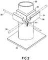
- FIG. 2is a perspective view of an electrical connector attached to one of the pedestals
- FIG. 5is a perspective view of another one of the members of the connector shown in FIGS. 2-3 ;
- FIGS. 6-9are perspective views an alternate embodiment of one of the sections of the connector shown in FIGS. 2-3 .
- FIG. 1there is shown a view of a raised floor system 10 incorporating features of the invention.
- a view of a raised floor system 10incorporating features of the invention.
- the inventionwill be described with reference to the example embodiments shown in the drawings, it should be understood that the invention can be embodied in many alternate forms of embodiments.
- any suitable size, shape or type of elements or materialscould be used.
- the system 10generally comprises pedestals 12 and panels 14 .
- the panels 14are conventional panels of a raised floor system.
- Each pedestal 12generally comprises a first section 16 and a second section 18 .
- the second section 18is adjustably connected to the first section 16 in this embodiment.
- the second sectionmight not be movably connected to the first section.
- the first section 16comprises a base 20 and a post 22 .
- the base and postare preferably comprised of metal.
- the post 22is stationarily attached to the base, such as by welding.
- the base and postcould be integrally formed or connected in any other suitable method.
- the base 20is sized and shaped to sit or rest on a floor, such as a concrete floor of an office building for example.
- the base 20has a general square or rectangular planar shape, but could have other shapes. In an alternate embodiment the base could be sized and shaped to connect to another member.
- the post 22extends upward from the base 20 .
- the post 22has a general tube shape. In the embodiment shown the tube shape is generally circular in cross section, but could have alternative cross sectional shapes.
- An apertureextends into the top end of the post 22 into the central channel of the tube shape.
- the second section 18generally comprises a post 26 and a top support 28 .
- the post 26 and top support 28are conventional in this embodiment.
- the post 26is a threaded post with threads on its exterior side.
- the top support 28is connected to the top end of the post 26 .
- the top side of the top support 28is adapted to support the panels 14 thereon.
- the second section 18comprises an adjuster, such as a nut.
- the adjusteris connected to the threads of the post 26 .
- the bottom side of the nutrests on the top end of the post 22 .
- any suitable type of height adjustment system between the first and second sectionscould be provided.
- the bottom end of the post 26extends into the center channel of the post 22 through the open top end of the post 22 .
- the post 26With the nut resting on the top support surface of the post 22 , when the nut is turned the post 26 can move up and down relative to the post 22 .
- the height of the top support 28 relative to the base 20can be adjusted.
- the system 10includes a grounding system which is used to ground the raised floor system to ground.
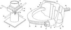
- the grounding systemincludes electrical conductors 30 , 32 and electrical ground connectors 34 .
- the connector 34generally comprises a first section 36 and a second section 38 .
- the first section 36generally comprises a first member 40 , a second member 42 and a worm drive 44 .
- the first member 40is a one-piece substantially rigid metal member.
- the first member 40has a general V shaped member 48 and a threaded post 46 .
- the member 48has two sections 50 , 52 which are generally orthogonal to each other. Exterior facing sides of the sections 50 , 52 each have two conductor receiving grooves 54 , 56 therealong. In this embodiment the grooves have different sizes, but they could have the same size.
- the opposite facing side 58is configured to be located directly against the exterior surface of the post 22 .
- the second member 42is pivotably connected to a first end 60 of the first member 40 at pivot connection 62 .
- the second member 42is a one-piece substantially rigid metal member having a general curved shape. However, the member 42 might not be rigid.
- a first end 64is pivotably connected at the pivot connection 62 .
- a side of the second member 42has teeth 66 which extend to a second end 68 of the second member 42 .
- the worm drive 44is located at the second end 70 of the first member 40 .
- the worm drive 44has a housing 72 formed by part of the first member 40 and a worm screw 74 in the housing 72 .
- the housing 72could be a separate member which is attached to the first member 40 .
- the housing 72is sized and shaped with an aperture 76 to allow the second end 68 of the second member to pass therethrough.
- the threads of the worm screw 74are sized and shaped to engage the teeth 66 on the second member 42 . When the screw 74 is rotated by a user, the second member 42 can be moved inward or outward relative to the aperture 76 .
- the space between opposite sides of the surface 58 of the first member 40 and the inward facing surface of the second member 42can be increased to decreased.
- the members 40 , 42can clamp the post 22 directly therebetween to mechanically and electrically connect the first section 36 to the post 22 .
- the second section 38has a one-piece member 78 and a fastener 81 (see FIG. 2 ), such as a nut.
- the one-piece member 78is preferably made of metal and comprises a general V shape with two generally orthogonal sections 80 , 82 and a through-hole 84 between the two generally orthogonal sections.
- the post 46is located through the through-hole 84 .
- the inner facing sides of the sections 80 , 82comprise conductor receiving grooves 86 , 88 .
- the conductors 30 , 32can be located in the grooves 54 , 56 , 86 , 88 and the nut 81 tightened to clamp the conductors directly between the members 40 , 78 .
- the conductors 30 , 32can be electrically connected to each other and to the post 22 .
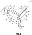
- the first sectionhas a one-piece metal member 90 comprising a threaded post 92 and a general C shaped section 94 .
- the threaded post 92is located at a first end of the C shaped section 94 .
- a screw 96is connected to an opposite second end of the C shaped section 94 .
- a tip of the screw 96can be tightened directly onto post 22 to attached the member 90 to the post.
- the member 78 and nut 81can be used on the threaded post 92 to clamp the conductors 30 , 32 directly against the exterior side of the post 22 .
- a ground connectorcomprising a first section comprising a first member 40 with a threaded post 46 , a second member 42 pivotably connected to the first member, and a worm drive 44 on the first member 40 , wherein the second member comprises teeth 66 configured to be engaged by the worm drive to clamp a pedestal directly between the first and second members; and a second section 38 movably located on the threaded post and configured to directly contact and clamp a conductor towards the pedestal.
- the first membercan comprise a general V shaped member 40 with an inner surface 58 sized and shaped to directly contact the pedestal, and outer surfaces having conductor receiving grooves 54 , 56 .
- the outer surfaces of the first membercan comprise two surfaces which are generally orthogonal to each other.
- the second sectioncan comprise a one piece member 78 having a general V shape with two generally orthogonal sections and a through-hole 84 between the two generally orthogonal sections, wherein the post 46 extends through the through-hole.
- the two generally orthogonal sections 80 , 82can have inward facing sides with conductor receiving grooves 86 , 88 therealong.
- a fastener 81 on the post 46can be configured to press the one piece member 78 towards the pedestal.
- the second member 42can be a one piece member having a general curved shape with a first end pivotably connected to a first end of the first member, and a second end having the teeth thereon, and wherein the worm drive is rotatably connected to a second end of the first member.
- a ground connectorcan be provided comprising a first section comprising a first member 40 , 90 with a threaded post 46 , 92 , and a system comprising a screw 74 , 96 configured to clamp the first section against opposite sides of a support 22 ; and a second section 42 movably located on the threaded post and configured to directly contact and clamp a conductor towards the support.
- the first membercan be a one-piece member with a general C shaped section 94 and the threaded post extending from one end of the C shaped section, and wherein the screw is connected to an opposite second end of the general C shaped section, and wherein an end of the screw is located to directly contact the support.
- a methodcomprising connecting a first section of a ground connector to a pedestal, wherein the first section comprises a first member with a threaded post, a second member pivotably connected to the first member, and a worm drive on the first member, wherein the second member comprises teeth engaged by the worm drive to clamp a pedestal directly between the first and second members; and positioning a second section on the threaded post to directly contact and clamp a conductor towards the pedestal.
Landscapes
- Details Of Connecting Devices For Male And Female Coupling (AREA)
- Coupling Device And Connection With Printed Circuit (AREA)
Abstract
Description
Claims (18)
Priority Applications (2)
| Application Number | Priority Date | Filing Date | Title |
|---|---|---|---|
| US12/380,511US8038453B2 (en) | 2009-02-27 | 2009-02-27 | Ground connector |
| CA2692105ACA2692105C (en) | 2009-02-27 | 2010-02-03 | Ground connector |
Applications Claiming Priority (1)
| Application Number | Priority Date | Filing Date | Title |
|---|---|---|---|
| US12/380,511US8038453B2 (en) | 2009-02-27 | 2009-02-27 | Ground connector |
Publications (2)
| Publication Number | Publication Date |
|---|---|
| US20100221934A1 US20100221934A1 (en) | 2010-09-02 |
| US8038453B2true US8038453B2 (en) | 2011-10-18 |
Family
ID=42663746
Family Applications (1)
| Application Number | Title | Priority Date | Filing Date |
|---|---|---|---|
| US12/380,511Active2030-01-25US8038453B2 (en) | 2009-02-27 | 2009-02-27 | Ground connector |
Country Status (2)
| Country | Link |
|---|---|
| US (1) | US8038453B2 (en) |
| CA (1) | CA2692105C (en) |
Cited By (7)
| Publication number | Priority date | Publication date | Assignee | Title |
|---|---|---|---|---|
| US20100299909A1 (en)* | 2009-02-27 | 2010-12-02 | Burndy Technology Llc | Ground connector |
| US20120088380A1 (en)* | 2010-10-07 | 2012-04-12 | Smith Lawrence J | Electric ground clamp with pivoted jaws and single attached adjusting bolt and terminal block |
| US9787004B2 (en) | 2015-05-20 | 2017-10-10 | Thomas & Betts International Llc | Floor ground clamp |
| US20180294582A1 (en)* | 2017-04-05 | 2018-10-11 | Mike Vernica | Armored Cable Ground Clamp |
| US10811791B2 (en) | 2018-02-05 | 2020-10-20 | Panduit Corp. | Grounding cross connectors including clamping pads for coupling at least two conductors |
| US12000267B2 (en) | 2021-09-24 | 2024-06-04 | DynaEnergetics Europe GmbH | Communication and location system for an autonomous frack system |
| US12312925B2 (en) | 2021-12-22 | 2025-05-27 | DynaEnergetics Europe GmbH | Manually oriented internal shaped charge alignment system and method of use |
Families Citing this family (3)
| Publication number | Priority date | Publication date | Assignee | Title |
|---|---|---|---|---|
| US8938918B2 (en)* | 2008-12-22 | 2015-01-27 | Hubbell Incorporated | Raised floor system grounding |
| US8864502B2 (en) | 2012-05-04 | 2014-10-21 | Thomas & Betts International, Inc. | Mechanical grounding connector |
| CN114171947B (en)* | 2021-11-26 | 2023-12-01 | 贵州电网有限责任公司 | Junction pole with telescopic supporting rod |
Citations (25)
| Publication number | Priority date | Publication date | Assignee | Title |
|---|---|---|---|---|
| US774099A (en) | 1904-03-10 | 1904-11-01 | Joseph Maxfield Narsh | Fence-post. |
| US846202A (en) | 1906-09-21 | 1907-03-05 | Philip J Harrah | Fence-post. |
| US1056173A (en) | 1912-11-06 | 1913-03-18 | Henry Higgin | Metal fence-post. |
| US2364419A (en) | 1943-05-06 | 1944-12-05 | Elza C Barnes | Fence post |
| US2915268A (en) | 1955-05-17 | 1959-12-01 | Parisienne De Const Electromec | Ring clamp |
| US2942898A (en) | 1958-04-23 | 1960-06-28 | Burndy Corp | Connector |
| US3435126A (en) | 1967-01-04 | 1969-03-25 | Douglas L P Hamilton | Means securing a cable sheath to a grounding and supporting member |
| US3861771A (en) | 1973-11-23 | 1975-01-21 | Electro Clamp Corp | Cable connector with five point grip and non-twist, non-pullout function and with ratchet latch |
| US4114977A (en) | 1977-05-09 | 1978-09-19 | Utm Power Products, Inc. | Single wedge-type grid wire connector |
| US4303216A (en) | 1979-06-25 | 1981-12-01 | Hollingsead International, Inc. | Releasable clamp assembly |
| US4428104A (en) | 1982-03-09 | 1984-01-31 | Communications Technology Corporation | Ground clamp |
| USRE31689E (en) | 1978-04-25 | 1984-10-02 | Panduit Corp. | Cable tie |
| US5286211A (en) | 1993-01-29 | 1994-02-15 | The Whitaker Corporation | Ground connector |
| US5632633A (en)* | 1994-01-17 | 1997-05-27 | The Whitaker Corporation | Method of manufacturing a grounding connector and improved grounding connector |
| USD389052S (en) | 1996-02-07 | 1998-01-13 | Nifco Inc. | Clamp |
| US5729872A (en) | 1996-12-06 | 1998-03-24 | Ginocchio; Mark H. | Method of storing bundled items |
| USD473130S1 (en) | 2001-08-28 | 2003-04-15 | Gloria Island Ltd. | Cable clamp with grounding connection |
| US6742223B1 (en) | 2003-01-28 | 2004-06-01 | Chun Yuan Chang | Clamping device for storing bundled items |
| US6763555B2 (en) | 2002-02-07 | 2004-07-20 | The United Seal Company | Uni-directional worm drive clamp |
| US6986673B2 (en)* | 2004-04-09 | 2006-01-17 | Thomas & Betts International, Inc. | Grounding clamp for raised floor |
| US7052331B2 (en) | 2003-09-25 | 2006-05-30 | Maxwell Scott D | Symmetrically adjustable corrosion-resistant battery cable connector |
| US7096543B2 (en) | 2001-11-09 | 2006-08-29 | Peter Castellanos | Clamp |
| US20080202794A1 (en) | 2007-02-22 | 2008-08-28 | Cho May K | Ratchet-head conductor locking medium voltage electrical bus polymer insulator with pin mount |
| US7794243B1 (en)* | 2009-02-27 | 2010-09-14 | Burndy Technology, LLC | Ground connector |
| US7803001B2 (en)* | 2008-12-10 | 2010-09-28 | Burndy Technology, LLC | Ground connector |
- 2009
- 2009-02-27USUS12/380,511patent/US8038453B2/enactiveActive
- 2010
- 2010-02-03CACA2692105Apatent/CA2692105C/enactiveActive
Patent Citations (25)
| Publication number | Priority date | Publication date | Assignee | Title |
|---|---|---|---|---|
| US774099A (en) | 1904-03-10 | 1904-11-01 | Joseph Maxfield Narsh | Fence-post. |
| US846202A (en) | 1906-09-21 | 1907-03-05 | Philip J Harrah | Fence-post. |
| US1056173A (en) | 1912-11-06 | 1913-03-18 | Henry Higgin | Metal fence-post. |
| US2364419A (en) | 1943-05-06 | 1944-12-05 | Elza C Barnes | Fence post |
| US2915268A (en) | 1955-05-17 | 1959-12-01 | Parisienne De Const Electromec | Ring clamp |
| US2942898A (en) | 1958-04-23 | 1960-06-28 | Burndy Corp | Connector |
| US3435126A (en) | 1967-01-04 | 1969-03-25 | Douglas L P Hamilton | Means securing a cable sheath to a grounding and supporting member |
| US3861771A (en) | 1973-11-23 | 1975-01-21 | Electro Clamp Corp | Cable connector with five point grip and non-twist, non-pullout function and with ratchet latch |
| US4114977A (en) | 1977-05-09 | 1978-09-19 | Utm Power Products, Inc. | Single wedge-type grid wire connector |
| USRE31689E (en) | 1978-04-25 | 1984-10-02 | Panduit Corp. | Cable tie |
| US4303216A (en) | 1979-06-25 | 1981-12-01 | Hollingsead International, Inc. | Releasable clamp assembly |
| US4428104A (en) | 1982-03-09 | 1984-01-31 | Communications Technology Corporation | Ground clamp |
| US5286211A (en) | 1993-01-29 | 1994-02-15 | The Whitaker Corporation | Ground connector |
| US5632633A (en)* | 1994-01-17 | 1997-05-27 | The Whitaker Corporation | Method of manufacturing a grounding connector and improved grounding connector |
| USD389052S (en) | 1996-02-07 | 1998-01-13 | Nifco Inc. | Clamp |
| US5729872A (en) | 1996-12-06 | 1998-03-24 | Ginocchio; Mark H. | Method of storing bundled items |
| USD473130S1 (en) | 2001-08-28 | 2003-04-15 | Gloria Island Ltd. | Cable clamp with grounding connection |
| US7096543B2 (en) | 2001-11-09 | 2006-08-29 | Peter Castellanos | Clamp |
| US6763555B2 (en) | 2002-02-07 | 2004-07-20 | The United Seal Company | Uni-directional worm drive clamp |
| US6742223B1 (en) | 2003-01-28 | 2004-06-01 | Chun Yuan Chang | Clamping device for storing bundled items |
| US7052331B2 (en) | 2003-09-25 | 2006-05-30 | Maxwell Scott D | Symmetrically adjustable corrosion-resistant battery cable connector |
| US6986673B2 (en)* | 2004-04-09 | 2006-01-17 | Thomas & Betts International, Inc. | Grounding clamp for raised floor |
| US20080202794A1 (en) | 2007-02-22 | 2008-08-28 | Cho May K | Ratchet-head conductor locking medium voltage electrical bus polymer insulator with pin mount |
| US7803001B2 (en)* | 2008-12-10 | 2010-09-28 | Burndy Technology, LLC | Ground connector |
| US7794243B1 (en)* | 2009-02-27 | 2010-09-14 | Burndy Technology, LLC | Ground connector |
Cited By (10)
| Publication number | Priority date | Publication date | Assignee | Title |
|---|---|---|---|---|
| US20100299909A1 (en)* | 2009-02-27 | 2010-12-02 | Burndy Technology Llc | Ground connector |
| US8341822B2 (en)* | 2009-02-27 | 2013-01-01 | Hubbell Incorporated | Ground connector |
| US20120088380A1 (en)* | 2010-10-07 | 2012-04-12 | Smith Lawrence J | Electric ground clamp with pivoted jaws and single attached adjusting bolt and terminal block |
| US8449308B2 (en)* | 2010-10-07 | 2013-05-28 | Bridgeport Fittings, Inc. | Electric ground clamp with pivoted jaws and single attached adjusting bolt and terminal block |
| US9787004B2 (en) | 2015-05-20 | 2017-10-10 | Thomas & Betts International Llc | Floor ground clamp |
| US20180294582A1 (en)* | 2017-04-05 | 2018-10-11 | Mike Vernica | Armored Cable Ground Clamp |
| US10811791B2 (en) | 2018-02-05 | 2020-10-20 | Panduit Corp. | Grounding cross connectors including clamping pads for coupling at least two conductors |
| US11251547B2 (en) | 2018-02-05 | 2022-02-15 | Panduit Corp. | Grounding cross connectors including clamping pads for coupling at least two conductors |
| US12000267B2 (en) | 2021-09-24 | 2024-06-04 | DynaEnergetics Europe GmbH | Communication and location system for an autonomous frack system |
| US12312925B2 (en) | 2021-12-22 | 2025-05-27 | DynaEnergetics Europe GmbH | Manually oriented internal shaped charge alignment system and method of use |
Also Published As
| Publication number | Publication date |
|---|---|
| CA2692105A1 (en) | 2010-08-27 |
| US20100221934A1 (en) | 2010-09-02 |
| CA2692105C (en) | 2017-09-12 |
Similar Documents
| Publication | Publication Date | Title |
|---|---|---|
| US7794243B1 (en) | Ground connector | |
| US8038453B2 (en) | Ground connector | |
| US7803001B2 (en) | Ground connector | |
| US10227783B2 (en) | Raised floor system grounding | |
| US20220263458A1 (en) | Rail accessory mount | |
| US6986673B2 (en) | Grounding clamp for raised floor | |
| CN102640356B (en) | Elastic terminal | |
| US9714671B2 (en) | End clip for recessed rail | |
| JPH06243912A (en) | Grounding connector | |
| MX2012005795A (en) | Salt form of a multi-arm polymer-drug conjugate. | |
| US7650725B2 (en) | Floor access panel with electrical grounding device | |
| US20120108112A1 (en) | Swivel Ground Clamp for Bare Armor Wire | |
| US10673190B2 (en) | Pad extending member | |
| US20210310610A1 (en) | Display mounting bracket | |
| US8313334B2 (en) | Pedestal ground connector | |
| JP2012199518A (en) | Conductive device as component of solar power generation array | |
| KR101127466B1 (en) | Support for conducting wire of a thunderbolt with lightening rod | |
| CN203356895U (en) | Harness clamping position fixing tool | |
| CN209880832U (en) | Lightning protection grounding body interconnection device | |
| KR20140089694A (en) | Support for conducting wire of a thunderbolt | |
| AU2016101448A4 (en) | Television antenna mounting assembly | |
| JP3164568U (en) | Outlet bar | |
| JPH045643Y2 (en) | ||
| JP2017184658A (en) | Fishing rod receiving fixture | |
| AU2016203189A1 (en) | Tiltable poles and accessories |
Legal Events
| Date | Code | Title | Description |
|---|---|---|---|
| AS | Assignment | Owner name:FCI AMERICAS TECHNOLOGY, INC., NEVADA Free format text:ASSIGNMENT OF ASSIGNORS INTEREST;ASSIGNORS:ROBICHEAU, RICHARD E.;RZASA, MICHAEL;REEL/FRAME:023209/0455 Effective date:20090828 | |
| AS | Assignment | Owner name:BURNDY TECHNOLOGY LLC, NEW HAMPSHIRE Free format text:ASSIGNMENT OF ASSIGNORS INTEREST;ASSIGNOR:FCI AMERICAS TECHNOLOGY, INC.;REEL/FRAME:023618/0888 Effective date:20091203 | |
| AS | Assignment | Owner name:HUBBELL INCORPORATED, CONNECTICUT Free format text:ASSIGNMENT OF ASSIGNORS INTEREST;ASSIGNOR:BURNDY TECHNOLOGY LLC;REEL/FRAME:025406/0729 Effective date:20101104 | |
| FEPP | Fee payment procedure | Free format text:PAYOR NUMBER ASSIGNED (ORIGINAL EVENT CODE: ASPN); ENTITY STATUS OF PATENT OWNER: LARGE ENTITY | |
| STCF | Information on status: patent grant | Free format text:PATENTED CASE | |
| FPAY | Fee payment | Year of fee payment:4 | |
| FEPP | Fee payment procedure | Free format text:MAINTENANCE FEE REMINDER MAILED (ORIGINAL EVENT CODE: REM.); ENTITY STATUS OF PATENT OWNER: LARGE ENTITY | |
| FEPP | Fee payment procedure | Free format text:7.5 YR SURCHARGE - LATE PMT W/IN 6 MO, LARGE ENTITY (ORIGINAL EVENT CODE: M1555); ENTITY STATUS OF PATENT OWNER: LARGE ENTITY | |
| MAFP | Maintenance fee payment | Free format text:PAYMENT OF MAINTENANCE FEE, 8TH YEAR, LARGE ENTITY (ORIGINAL EVENT CODE: M1552); ENTITY STATUS OF PATENT OWNER: LARGE ENTITY Year of fee payment:8 | |
| FEPP | Fee payment procedure | Free format text:MAINTENANCE FEE REMINDER MAILED (ORIGINAL EVENT CODE: REM.); ENTITY STATUS OF PATENT OWNER: LARGE ENTITY | |
| FEPP | Fee payment procedure | Free format text:11.5 YR SURCHARGE- LATE PMT W/IN 6 MO, LARGE ENTITY (ORIGINAL EVENT CODE: M1556); ENTITY STATUS OF PATENT OWNER: LARGE ENTITY | |
| MAFP | Maintenance fee payment | Free format text:PAYMENT OF MAINTENANCE FEE, 12TH YEAR, LARGE ENTITY (ORIGINAL EVENT CODE: M1553); ENTITY STATUS OF PATENT OWNER: LARGE ENTITY Year of fee payment:12 |