US8038371B2 - Push button holesaw mandrel assembly - Google Patents
Push button holesaw mandrel assemblyDownload PDFInfo
- Publication number
- US8038371B2 US8038371B2US11/787,267US78726707AUS8038371B2US 8038371 B2US8038371 B2US 8038371B2US 78726707 AUS78726707 AUS 78726707AUS 8038371 B2US8038371 B2US 8038371B2
- Authority
- US
- United States
- Prior art keywords
- holesaw
- push button
- mandrel assembly
- mandrel
- rollers
- Prior art date
- Legal status (The legal status is an assumption and is not a legal conclusion. Google has not performed a legal analysis and makes no representation as to the accuracy of the status listed.)
- Active, expires
Links
Images


Classifications
- B—PERFORMING OPERATIONS; TRANSPORTING
- B23—MACHINE TOOLS; METAL-WORKING NOT OTHERWISE PROVIDED FOR
- B23B—TURNING; BORING
- B23B51/00—Tools for drilling machines
- B23B51/04—Drills for trepanning
- B23B51/0473—Details about the connection between the driven shaft and the tubular cutting part; Arbors
- Y—GENERAL TAGGING OF NEW TECHNOLOGICAL DEVELOPMENTS; GENERAL TAGGING OF CROSS-SECTIONAL TECHNOLOGIES SPANNING OVER SEVERAL SECTIONS OF THE IPC; TECHNICAL SUBJECTS COVERED BY FORMER USPC CROSS-REFERENCE ART COLLECTIONS [XRACs] AND DIGESTS
- Y10—TECHNICAL SUBJECTS COVERED BY FORMER USPC
- Y10T—TECHNICAL SUBJECTS COVERED BY FORMER US CLASSIFICATION
- Y10T403/00—Joints and connections
- Y10T403/70—Interfitted members
- Y10T403/7005—Lugged member, rotary engagement
- Y—GENERAL TAGGING OF NEW TECHNOLOGICAL DEVELOPMENTS; GENERAL TAGGING OF CROSS-SECTIONAL TECHNOLOGIES SPANNING OVER SEVERAL SECTIONS OF THE IPC; TECHNICAL SUBJECTS COVERED BY FORMER USPC CROSS-REFERENCE ART COLLECTIONS [XRACs] AND DIGESTS
- Y10—TECHNICAL SUBJECTS COVERED BY FORMER USPC
- Y10T—TECHNICAL SUBJECTS COVERED BY FORMER US CLASSIFICATION
- Y10T408/00—Cutting by use of rotating axially moving tool
- Y10T408/89—Tool or Tool with support
- Y10T408/895—Having axial, core-receiving central portion
- Y—GENERAL TAGGING OF NEW TECHNOLOGICAL DEVELOPMENTS; GENERAL TAGGING OF CROSS-SECTIONAL TECHNOLOGIES SPANNING OVER SEVERAL SECTIONS OF THE IPC; TECHNICAL SUBJECTS COVERED BY FORMER USPC CROSS-REFERENCE ART COLLECTIONS [XRACs] AND DIGESTS
- Y10—TECHNICAL SUBJECTS COVERED BY FORMER USPC
- Y10T—TECHNICAL SUBJECTS COVERED BY FORMER US CLASSIFICATION
- Y10T408/00—Cutting by use of rotating axially moving tool
- Y10T408/89—Tool or Tool with support
- Y10T408/907—Tool or Tool with support including detailed shank
- Y—GENERAL TAGGING OF NEW TECHNOLOGICAL DEVELOPMENTS; GENERAL TAGGING OF CROSS-SECTIONAL TECHNOLOGIES SPANNING OVER SEVERAL SECTIONS OF THE IPC; TECHNICAL SUBJECTS COVERED BY FORMER USPC CROSS-REFERENCE ART COLLECTIONS [XRACs] AND DIGESTS
- Y10—TECHNICAL SUBJECTS COVERED BY FORMER USPC
- Y10T—TECHNICAL SUBJECTS COVERED BY FORMER US CLASSIFICATION
- Y10T408/00—Cutting by use of rotating axially moving tool
- Y10T408/94—Tool-support
- Y10T408/95—Tool-support with tool-retaining means
Definitions
- the present disclosurerelates to holesaws and, more particularly, to a mandrel assembly which receives holesaws.
- the base of the holesawdoes not include holes to receive the pins on the mandrel assemblies. This is due to the fact that the diameter of the base is too small to register with the pins. Also, during use, due to the threaded engagement of the spud with the small holesaw, the holesaw is torqued down onto the collar of the mandrel assembly. Accordingly, a wrench or the like is required to loosen the holesaw from the mandrel collar in order to remove the holesaw from the mandrel assembly.
- the artdoes not provide a small holesaw mandrel which enables the user to quickly remove, by hand, the holesaw from the mandrel assembly. Thus, it is desirable to have a mandrel assembly which enables the quick release of small diameter holesaws.
- the present disclosureprovides the art with a holesaw mandrel assembly which enables a quick release of holesaws from the mandrel assembly.
- the present holesaw mandrel assemblyprovides a friction face that abuts the holesaw. The friction face axially moves away from the holesaw into a release position. The holesaw assembly enables the friction face to move automatically back to its original position.
- the holesaw mandrel assemblyprovides a push button action to enable the axial movement of the friction face.
- a holesaw mandrel assemblycomprises a mandrel having a body with a first end to couple with a drill motor. A second end extends from the body. The second end includes a thread to receive a holesaw. A first member is positioned on the second end. The first member axially moves on the second end. A friction surface is on the first member. The friction surface is adapted to contact or engage a base surface of the holesaw such that upon contact with the friction surface, the holesaw is fixed in position. The friction surface moves between a first contact and second release position. A mechanism, on the first member, moves the friction surface between the first and second positions. The mechanism is biased to return the first member to its first position from its second or released position.
- the mechanismincludes a second member movable transverse to the mandrel axis to enable the axial movement of the first member. At least one roller is positioned between the first and second member.
- the second memberincludes a body including at least one recess to receive the at least one roller.
- the mechanismincludes at least one cage to retain the at least one roller.
- a holesaw mandrel assemblycomprises a mandrel which includes a body with a first end to couple with a drill motor. A second end extends from the body. The second end includes a thread to receive a holesaw. A first member is on the second end. The first member axially moves on the second end. A push button mechanism is coupled with the first member. At least one roller is associated with the push button mechanism. The at least one roller is in contact with the push button member. The push button member moves between a first and a second position to enable the first member to move axially along the second end.
- the push button mechanismWhen the push button mechanism is in its first position, the first member is fixed so that a holesaw may be screwed onto the thread and abuts the first member to secure a holesaw in a use position on the first member. When the push button mechanism is moved to its second position, the first member moves axially away from the holesaw to enable the holesaw to be easily removed from the thread.
- the push button mechanismincludes at least one recess which is adjacent to the at least one roller. When the push button mechanism is in its second position, the at least one roller is positioned in the at least one recess. A plurality of rollers is present with at least two rollers sandwiching the push button mechanism. A pair of friction plates are positioned such that the at least two roller each contact one of the pair of friction plates. A biasing member moves the push button mechanism between the first and second positions.
- a holesaw mandrel assemblycomprises a mandrel with a body which includes a first end to couple with a drill motor. A second end extends from the body. The second end includes a thread to receive a holesaw. A first member is on the second end. The first member axially moves on the second end. A friction surface is on the first member. The friction surface is adapted to contact the base surface of the holesaw such that upon contact with the friction surface, the holesaw is fixed in position. The friction surface moves between a first contact and a second release position.
- a mechanismis coupled with the first member to move the friction surface between the first and second positions. The mechanism comprises a push button member extending through the first member.
- the push button memberincludes a body member with two side faces with a plurality of recesses on each side face.
- a plurality of rollersequal in number to the plurality of recesses, is positioned on the two sides of the body member.
- the plurality of rollersis positioned adjacent to the plurality of recesses.
- the first memberis in its first position.
- the rollersare in the recesses, the first member is in the second position.
- the push button membermoves between the first and second positions, via a spring, wherein the plurality of rollers move in and out of the adjacent recesses.
- a pair or cagesretain the roller in position.
- a pair of friction membersare positioned adjacent the rollers. One friction member is on each side of the push button member and in contact with the rollers.
- FIG. 1is a perspective view of a holesaw mandrel.
- FIG. 2is a cross section view of the mandrel of FIG. 1 in a first position.
- FIG. 3is a view like FIG. 2 in a second position.
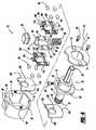
- FIG. 4is an exploded perspective view of the mandrel of FIG. 1 .
- the mandrel assembly 10includes a mandrel 12 , a first movable member 14 , and a mechanism 16 for moving the first member 14 between a first and second position.
- the mandrel 12includes a body 18 with a first projecting end 20 and a second extending end 22 .
- the first projecting end 20is cylindrical and may have an outer polygonal surface to connect the mandrel 12 with a rotating tool, such as a drill.
- the body 18has a first cylindrical portion 24 and a larger plate portion 26 .
- the first portion 24includes an aperture 28 to receive a fastener 30 which retains a pilot drill bit 32 in a bore 34 .
- the pilot drill bit 32extends through the second extending member 22 .
- the second plate 26has an overall elongated D-shape and includes a flat receiving surface 36 .
- the second extending end 22 of the mandrel 12includes a first cylindrical portion 40 and a threaded spud 42 .
- the threaded spud 42receives a holesaw 38 in a conventional manner.
- the first cylindrical portion 40extends from the larger second plate portion 26 .
- the first member 14has an overall cup shaped configuration.
- the first memberincludes a bore 48 through the base portion 50 of the cup shaped first member 14 .
- the base portion 50includes a friction face 52 which receives the base of the holesaw 38 as seen in FIG. 2 .
- the bore 48enables the first member 14 to be positioned on the second end 22 of the mandrel 12 .
- the bore 48opens into a larger cylindrical open space 54 inside the cylindrical wall 56 of the cup shaped first member 14 .
- the wall 56includes an arcuate cut-out portion 58 as well as a bore 60 which receives a portion of the moving mechanism 16 .
- a back plate 62is connected with the wall 56 .
- the back plate 62is substantially parallel to the base portion 50 .
- the back plate 62includes a pair of apertures 64 which receive fasteners 68 to retain a securement plate 70 onto the first member 14 .
- the securement plate 70includes an aperture 71 to receive the mandrel cylindrical portion 24 as well as a pair of apertures 73 to receive fasteners 68 .
- the back plate 62includes a cut-out 72 , having an overall elongated D-shape, to receive the moving mechanism 16 and the mandrel plate portion 26 .
- the mechanism 16which moves the first member 14 between a first and second position, is positioned transverse to the longitudinal axis 74 of the mandrel 12 .
- the mechanism 16includes a push button 80 which is positioned in the aperture 60 .
- the push button 80through its movement which will be explained later, enables the axial movement of the first member 14 on the mandrel 12 .
- the push button 80is coupled with or unitarily formed with a plate member 82 .
- the plate member 82includes a projection 84 which seats inside of the push button 80 .
- the plate member 82has an overall rectangular annular shape with an elongated elliptical opening 86 in the middle of the plate member 82 .
- the elliptical opening 86receives the mandrel second end 22 .
- the plate member 82includes a pair of side faces 88 and 90 .
- the side faces 88 and 90each include at least one and preferably a plurality of recesses 92 .
- the plate member 82includes a tail 94 and recess 95 which are associated with the biasing spring 96 .
- the spring 96biases the push button 80 between its first and second positions.
- At least one and preferably a plurality of rollers 98are positioned on each side face 88 and 90 of the plate member 82 .
- the rollers 98when the push button 80 is in a first position as seen in FIG. 2 , rest on the planar side faces 88 , 90 of the plate member 82 . In the push button 80 second position as seen in FIG. 3 , the rollers move from the planar side faces 88 , 90 into the recesses 92 .
- a pair of cages 100 and 102holds the rollers 98 in position.
- the cages 100 and 102are identical and the disclosure of one equally applies to the other.
- the cages 100 , 102have an overall rectangular shape with an elliptical aperture 104 , to receive the mandrel second end 22 , in the middle of the body 106 .
- the body 106has two sides 108 and 110 , each of which includes at least one, and shown with a pair of apertures 112 .
- the apertures 112receive the rollers 98 in the cages 100 and 102 .
- a projecting member 114extends from the body 106 into the push button member 80 .
- a cut out 116is opposite the projecting member 114 to enable the biasing spring 96 to seat in the cut out portion 116 .
- a pair of friction plates 118 and 120sandwiches the rollers and cages against the plate 82 .
- the friction plates 118 and 120are substantially identical and the explanation with respect to one applies to both.
- the friction plates 118have an overall D shape with a circular aperture 122 .
- the aperture 122is circular and sized to fit onto the second extending member 22 of the mandrel 12 .
- the friction plates 118 and 120have flat planar surfaces 124 and 126 .
- the flat planar surfaces 124 , 126provide a rolling surface for the rollers 98 .
- One of the flat planar surfaces of the plate 118abuts the flat surface 36 of the second plate member 26 of the mandrel 12 while the other abuts the flat inside surface of base 50 . It should be noted that the friction plates may be removed and the flat surface 36 and inside surface of the base 50 may be used as the rolling surfaces for the rollers 98 .
- the friction plates 118 and 120 as well as cages 100 and 102 with rollers 98 sandwiching plate 82are all positioned onto the extending member 22 of the mandrel 12 . This is best illustrated in FIGS. 2 and 3 .
- the biasing spring 96abuts one side of the wall 56 opposite to the aperture 60 .
- the push button 80projects from the aperture 60 in the arcuate cut out portion 58 .
- the plate 70 and the screw 68retain the mandrel 12 in an assembled position with the first member 14 and the moving mechanism 16 , positioned inside of the first member 14 , on the mandrel 12 .
- a holesaw 38is screwed onto spud 42 until it abuts the friction surface 52 of the first member 14 (see FIG. 2 ). At this time, the holesaw 38 is in a use position abutting the friction surface 52 which receives the force from the holesaw 38 torque during operation.
- the holesaw 38is removed from the mandrel. In order to do this, push button 80 is moved inward tranversed to the longitudinal axis 74 of the mandrel 12 . As this occurs, plate 82 is moved laterally against the spring 96 . As the plate 82 continues to move, the cages 100 and 102 move laterally half the distance of the plate 82 .
- the rollers 98fall into the recesses 92 in the plate 82 .
- the first member 14moves away from a holesaw 38 as seen in FIG. 3 .
- a gap 130is created between the holesaw 38 and the friction surface 52 of the first member 14 . This enables the user to easily remove the holesaw 38 from the threaded spud 42 .
- the spring 96is able to move the plate 82 as well as the cages 100 , 102 , it enables the cages 100 , 102 and plate 82 to align and register with one another so that the rollers 98 are in a proper first position with respect to the recesses 92 as shown in FIG. 2 .
- the mandrel assembly 10is ready for its next use.
Landscapes
- Engineering & Computer Science (AREA)
- Mechanical Engineering (AREA)
- Rolls And Other Rotary Bodies (AREA)
- Jigs For Machine Tools (AREA)
Abstract
Description
Claims (15)
Priority Applications (4)
| Application Number | Priority Date | Filing Date | Title |
|---|---|---|---|
| US11/787,267US8038371B2 (en) | 2007-04-13 | 2007-04-13 | Push button holesaw mandrel assembly |
| US12/062,787US8038372B2 (en) | 2007-04-13 | 2008-04-04 | Push button holesaw mandrel assembly |
| EP12189987.6AEP2604367B1 (en) | 2007-04-13 | 2008-04-10 | Holesaw mandrel assembly |
| EP08154347.2AEP1982785B1 (en) | 2007-04-13 | 2008-04-10 | Holesaw mandrel assembly |
Applications Claiming Priority (1)
| Application Number | Priority Date | Filing Date | Title |
|---|---|---|---|
| US11/787,267US8038371B2 (en) | 2007-04-13 | 2007-04-13 | Push button holesaw mandrel assembly |
Related Child Applications (1)
| Application Number | Title | Priority Date | Filing Date |
|---|---|---|---|
| US12/062,787Continuation-In-PartUS8038372B2 (en) | 2007-04-13 | 2008-04-04 | Push button holesaw mandrel assembly |
Publications (2)
| Publication Number | Publication Date |
|---|---|
| US20080253851A1 US20080253851A1 (en) | 2008-10-16 |
| US8038371B2true US8038371B2 (en) | 2011-10-18 |
Family
ID=39853858
Family Applications (1)
| Application Number | Title | Priority Date | Filing Date |
|---|---|---|---|
| US11/787,267Active2030-07-31US8038371B2 (en) | 2007-04-13 | 2007-04-13 | Push button holesaw mandrel assembly |
Country Status (1)
| Country | Link |
|---|---|
| US (1) | US8038371B2 (en) |
Cited By (4)
| Publication number | Priority date | Publication date | Assignee | Title |
|---|---|---|---|---|
| US20090136310A1 (en)* | 2007-11-28 | 2009-05-28 | Michael Naughton | Cutting tool assembly including a release mechanism |
| US8827604B1 (en)* | 2010-08-09 | 2014-09-09 | Tim Corey | Hole saw apparatus |
| US20160345619A1 (en)* | 2014-12-02 | 2016-12-01 | Monarch Media Llc. | Coconut removal device and method therefor |
| US11317647B2 (en)* | 2014-12-02 | 2022-05-03 | Monarch Media, Llc | Coconut water removal device and method therefor |
Families Citing this family (4)
| Publication number | Priority date | Publication date | Assignee | Title |
|---|---|---|---|---|
| US8434976B2 (en)* | 2009-03-20 | 2013-05-07 | Black & Decker Inc. | Small hole saw mandrel assembly |
| US8721236B2 (en)* | 2009-10-23 | 2014-05-13 | Milwaukee Electric Tool Corporation | Power tool arbor device |
| BR112012026814A2 (en)* | 2010-04-20 | 2016-07-12 | Starrett L S Co | spindle and hollow saw spindle system |
| WO2016068716A1 (en)* | 2014-10-29 | 2016-05-06 | Ztools As | Hole saw speed coupler |
Citations (80)
| Publication number | Priority date | Publication date | Assignee | Title |
|---|---|---|---|---|
| US2435648A (en) | 1945-08-27 | 1948-02-10 | Bart W Frevel | Hole cutter |
| US2778091A (en)* | 1955-02-28 | 1957-01-22 | Palley Zoltan O St | Hole saw |
| US2779361A (en)* | 1954-03-17 | 1957-01-29 | Miller Mfg Corp | Sawing tool for cutting circular holes |
| US2917975A (en)* | 1955-09-29 | 1959-12-22 | Sheffield Twist Drill & Steel | Arbors for milling machine cutters and like rotary tools |
| US3220449A (en) | 1964-03-04 | 1965-11-30 | Robert P Franklin | Self-cleaning hole saw |
| US3267975A (en) | 1964-06-16 | 1966-08-23 | Black & Decker Mfg Co | Coupling means for hole saw assembly |
| US3293740A (en) | 1964-06-16 | 1966-12-27 | Black & Decker Mfg Co | Method of producing a hole saw mandrel |
| US3360025A (en) | 1965-09-14 | 1967-12-26 | Sr John Gallo | Double edge hole saw and mandrel |
| US3758221A (en) | 1971-12-29 | 1973-09-11 | Black & Decker Mfg Co | Hole saw assembly |
| US3784316A (en) | 1972-07-12 | 1974-01-08 | Capewell Mfg Co | Hole saw and reversible quick disconnect drive therefor |
| US3825362A (en)* | 1973-02-26 | 1974-07-23 | Hougen Everett | Arbor for an annular hole cutter |
| US3837759A (en) | 1972-07-12 | 1974-09-24 | Capewell Mfg Co | Hole saw and quick disconnect drive therefor |
| US3880546A (en) | 1974-03-13 | 1975-04-29 | Segal F | Hole saw assembly |
| US3970407A (en) | 1974-11-25 | 1976-07-20 | Uffman Leroy E | Rotary cutter |
| US3973862A (en)* | 1975-06-02 | 1976-08-10 | Segal F | Pilot drill locating means for hole saw assembly |
| US4036560A (en) | 1975-11-03 | 1977-07-19 | Stanadyne, Inc. | Heavy duty hole saw and arbor assembly |
| US4072441A (en) | 1976-04-15 | 1978-02-07 | Parker Manufacturing Company | Hole saw |
| US4077737A (en) | 1976-10-18 | 1978-03-07 | Morse Mansfield K | Integral hole saw and arbor construction |
| US4303357A (en) | 1980-05-19 | 1981-12-01 | William Makar | Quick-change hole saw mandrel |
| US4422811A (en) | 1981-01-16 | 1983-12-27 | Ingersoll-Rand Company | Hole saw |
| US4490080A (en) | 1983-02-18 | 1984-12-25 | Precision Industries, Inc. | Hole cutting tool |
| US4588335A (en) | 1984-09-14 | 1986-05-13 | Pearson Jr Claude C | Quick change tool retention device for power operated mechanism |
| US4669928A (en) | 1986-10-07 | 1987-06-02 | Eugenio Mediavilla | Hole saw mandrel |
| US4741651A (en) | 1986-04-25 | 1988-05-03 | Despres Roger J | Hole saw |
| US4755087A (en) | 1987-03-13 | 1988-07-05 | Parent Philip V | Hole saw plug ejector |
| US4929128A (en)* | 1989-06-23 | 1990-05-29 | Affleck Robert J | Masonry drill assembly |
| US4968189A (en) | 1989-10-20 | 1990-11-06 | Pidgeon Joseph A | Hole saw driver-extruder and hole enlarger |
| US5035548A (en) | 1990-10-31 | 1991-07-30 | Pidgeon Joseph A | Hole saw driver and extruder |
| US5061126A (en) | 1990-05-04 | 1991-10-29 | Rule Industries | Hole saw and mandrel assembly |
| US5076741A (en) | 1990-11-13 | 1991-12-31 | Littlehorn James M | Plug ejecting holesaw |
| US5096341A (en)* | 1986-04-25 | 1992-03-17 | Despres Roger J | Hole saw and drive |
| US5108235A (en) | 1991-05-14 | 1992-04-28 | Greenlee Textron Inc. | Hole saw arbor |
| US5154552A (en) | 1991-12-31 | 1992-10-13 | American Saw & Mfg. Company | Quick-release arbor for hole saws |
| US5171111A (en) | 1991-07-05 | 1992-12-15 | Kansai Kogu Manufacturing Co., Ltd. | Drilling tool |
| US5175963A (en)* | 1988-07-15 | 1993-01-05 | Robert Bosch Gmbh | Clamping device for axially clamping of a tool, especially a disc |
| GB2257381A (en) | 1991-07-09 | 1993-01-13 | Eldon Tool Company Limited | Arbor for hole saw. |
| US5226762A (en) | 1992-08-06 | 1993-07-13 | Ecker Robert J | Sealed hole-saw arbor |
| US5246317A (en) | 1991-12-31 | 1993-09-21 | American Saw & Mfg. Company | Quick-release arbor for hole saws |
| US5352071A (en) | 1993-06-07 | 1994-10-04 | Greenlee Textron Inc. | Hole saw arbor with retaining mechanism |
| US5429457A (en)* | 1993-06-30 | 1995-07-04 | Nitto Kohki Co., Ltd. | Annular cutter |
| US5435672A (en)* | 1994-08-05 | 1995-07-25 | Vermont American Corporation | Hole saw having plug ejection feature |
| US5597274A (en) | 1995-08-17 | 1997-01-28 | Behner; Ray E. | Hole cutter |
| US5624213A (en)* | 1995-05-11 | 1997-04-29 | Evergreen Tool Co., Inc. | Hole producing assembly |
| WO1997015413A1 (en) | 1995-10-27 | 1997-05-01 | Sandvik Ab: (Publ) | Hole saw |
| US5639193A (en)* | 1995-05-11 | 1997-06-17 | Evergreen Tool Co., Inc. | Cylindrical cutter |
| US5658102A (en) | 1995-09-12 | 1997-08-19 | The L. S. Starrett Company | Hole saw arbor method and apparatus |
| US5690452A (en) | 1996-06-27 | 1997-11-25 | Baublits; David G. | Spring loaded automatic plug ejector or hole saws |
| US5868532A (en) | 1997-03-24 | 1999-02-09 | American Saw & Mfg. Company | Arbor for engaging a saw |
| US5957636A (en) | 1998-08-15 | 1999-09-28 | Boisvert; Marc H. | Quick change tool locking and alignment system |
| US5967709A (en) | 1995-01-31 | 1999-10-19 | Thuesen; Jorgen | Adaptor for rotating tools |
| EP0951375A1 (en) | 1996-12-19 | 1999-10-27 | Sandvik Aktiebolag | Holesaw |
| EP0958083A1 (en) | 1995-10-18 | 1999-11-24 | THUESEN, Jorgen | Adaptor for rotating tools |
| US6341925B1 (en) | 2000-03-02 | 2002-01-29 | Roger J. Despres | Plug ejecting hole saw with twist-locking interchangeable saw cups |
| US6357973B2 (en) | 1999-06-28 | 2002-03-19 | Walley Chao | Connection device of boring saw |
| EP1193014A1 (en) | 2000-09-01 | 2002-04-03 | Credo Tool Company | Mandrel assembly for hole saw and drill bit |
| US6379089B1 (en) | 1999-06-30 | 2002-04-30 | Nicotec Co., Ltd. | Separation type hole saw |
| US20020122703A1 (en) | 2001-02-16 | 2002-09-05 | Peter Czyzewski | Quick change adaptor for hole saw |
| US6554292B1 (en) | 2001-06-20 | 2003-04-29 | Rohm Gmbh | Drill chuck for smooth- and hex-shank bits |
| US6604744B2 (en) | 2001-01-16 | 2003-08-12 | Newfrey Llc | Rapid load drill bit adapter |
| US6641338B2 (en) | 2000-03-02 | 2003-11-04 | Roger J. Despres | Plug ejecting hole saw with interchangeable saw cups having different size attachment bores |
| WO2004011179A1 (en) | 2002-07-26 | 2004-02-05 | Gsm Industrier Ab | Hole saw arbor |
| US6705807B1 (en) | 1999-11-24 | 2004-03-16 | Black & Decker Inc. | Hole saw and connection method |
| EP1462198A1 (en) | 2000-09-01 | 2004-09-29 | Credo Technology Corporation | Quick change mandrel assembly for hole saw and drill bit |
| WO2004085104A1 (en) | 2003-03-28 | 2004-10-07 | Kym John Keightley | An improved hole saw boss |
| WO2005000506A2 (en) | 2003-06-27 | 2005-01-06 | Jore Corporation | Hole saw arbor |
| US20050025591A1 (en)* | 2003-06-24 | 2005-02-03 | Korb William B. | Arbor for hole cutter and related method of use |
| US6851678B2 (en) | 2002-02-20 | 2005-02-08 | Rohm Gmbh | Drill for smooth- and hex-shank bits |
| US6887018B2 (en)* | 2002-07-23 | 2005-05-03 | Hilti Aktiengesellschaft | Chuck for annular core bit |
| EP1555076A1 (en) | 2004-01-17 | 2005-07-20 | A.V. Custom style B.V. | Quick change mandrel assembly and adapter for a hole saw and hole saw |
| WO2005120754A1 (en) | 2004-06-08 | 2005-12-22 | Kym John Keightley | A hole saw assembly |
| US7001116B2 (en)* | 2003-03-29 | 2006-02-21 | Eazypower Corporation | Workpiece removal device for a hole saw |
| US20060088393A1 (en) | 2004-10-26 | 2006-04-27 | Cooper Vincent P | Extended sleeve removable chuck |
| US7097397B2 (en) | 2003-08-22 | 2006-08-29 | Kym John Keightley | Hole-saw assembly including two hole-saws |
| US7101124B2 (en) | 2001-09-21 | 2006-09-05 | Kym John Keightley | Hole saw assembly |
| US7112016B2 (en) | 2003-02-18 | 2006-09-26 | Greenlee Textron Inc. | Universal quick change hole saw arbor |
| WO2006122417A1 (en) | 2005-05-17 | 2006-11-23 | Maxtech Consumer Products Limited | Universal quick connect system for a hole saw |
| US7163362B2 (en) | 2003-06-06 | 2007-01-16 | Keightley Kym John | Hole saw assembly |
| US7488146B2 (en)* | 2006-11-16 | 2009-02-10 | Black & Decker Inc. | Large holesaw mandrel assembly |
| US7517179B2 (en)* | 2006-11-16 | 2009-04-14 | Black & Decker Inc. | Small holesaw mandrel assembly |
| US20100239381A1 (en)* | 2009-03-20 | 2010-09-23 | Black & Decker Inc. | Small Hole Saw Mandrel Assembly |
- 2007
- 2007-04-13USUS11/787,267patent/US8038371B2/enactiveActive
Patent Citations (85)
| Publication number | Priority date | Publication date | Assignee | Title |
|---|---|---|---|---|
| US2435648A (en) | 1945-08-27 | 1948-02-10 | Bart W Frevel | Hole cutter |
| US2779361A (en)* | 1954-03-17 | 1957-01-29 | Miller Mfg Corp | Sawing tool for cutting circular holes |
| US2778091A (en)* | 1955-02-28 | 1957-01-22 | Palley Zoltan O St | Hole saw |
| US2917975A (en)* | 1955-09-29 | 1959-12-22 | Sheffield Twist Drill & Steel | Arbors for milling machine cutters and like rotary tools |
| US3220449A (en) | 1964-03-04 | 1965-11-30 | Robert P Franklin | Self-cleaning hole saw |
| US3267975A (en) | 1964-06-16 | 1966-08-23 | Black & Decker Mfg Co | Coupling means for hole saw assembly |
| US3293740A (en) | 1964-06-16 | 1966-12-27 | Black & Decker Mfg Co | Method of producing a hole saw mandrel |
| US3360025A (en) | 1965-09-14 | 1967-12-26 | Sr John Gallo | Double edge hole saw and mandrel |
| US3758221A (en) | 1971-12-29 | 1973-09-11 | Black & Decker Mfg Co | Hole saw assembly |
| US3784316A (en) | 1972-07-12 | 1974-01-08 | Capewell Mfg Co | Hole saw and reversible quick disconnect drive therefor |
| US3837759A (en) | 1972-07-12 | 1974-09-24 | Capewell Mfg Co | Hole saw and quick disconnect drive therefor |
| US3825362A (en)* | 1973-02-26 | 1974-07-23 | Hougen Everett | Arbor for an annular hole cutter |
| US3880546A (en) | 1974-03-13 | 1975-04-29 | Segal F | Hole saw assembly |
| US3970407A (en) | 1974-11-25 | 1976-07-20 | Uffman Leroy E | Rotary cutter |
| US3973862A (en)* | 1975-06-02 | 1976-08-10 | Segal F | Pilot drill locating means for hole saw assembly |
| US4036560A (en) | 1975-11-03 | 1977-07-19 | Stanadyne, Inc. | Heavy duty hole saw and arbor assembly |
| US4072441A (en) | 1976-04-15 | 1978-02-07 | Parker Manufacturing Company | Hole saw |
| US4077737A (en) | 1976-10-18 | 1978-03-07 | Morse Mansfield K | Integral hole saw and arbor construction |
| US4303357A (en) | 1980-05-19 | 1981-12-01 | William Makar | Quick-change hole saw mandrel |
| US4422811A (en) | 1981-01-16 | 1983-12-27 | Ingersoll-Rand Company | Hole saw |
| US4490080A (en) | 1983-02-18 | 1984-12-25 | Precision Industries, Inc. | Hole cutting tool |
| US4588335A (en) | 1984-09-14 | 1986-05-13 | Pearson Jr Claude C | Quick change tool retention device for power operated mechanism |
| US5096341A (en)* | 1986-04-25 | 1992-03-17 | Despres Roger J | Hole saw and drive |
| US4741651A (en) | 1986-04-25 | 1988-05-03 | Despres Roger J | Hole saw |
| US4669928A (en) | 1986-10-07 | 1987-06-02 | Eugenio Mediavilla | Hole saw mandrel |
| US4755087A (en) | 1987-03-13 | 1988-07-05 | Parent Philip V | Hole saw plug ejector |
| US5175963A (en)* | 1988-07-15 | 1993-01-05 | Robert Bosch Gmbh | Clamping device for axially clamping of a tool, especially a disc |
| US4929128A (en)* | 1989-06-23 | 1990-05-29 | Affleck Robert J | Masonry drill assembly |
| US4968189A (en) | 1989-10-20 | 1990-11-06 | Pidgeon Joseph A | Hole saw driver-extruder and hole enlarger |
| US5061126A (en) | 1990-05-04 | 1991-10-29 | Rule Industries | Hole saw and mandrel assembly |
| US5035548A (en) | 1990-10-31 | 1991-07-30 | Pidgeon Joseph A | Hole saw driver and extruder |
| US5076741A (en) | 1990-11-13 | 1991-12-31 | Littlehorn James M | Plug ejecting holesaw |
| US5108235A (en) | 1991-05-14 | 1992-04-28 | Greenlee Textron Inc. | Hole saw arbor |
| US5171111A (en) | 1991-07-05 | 1992-12-15 | Kansai Kogu Manufacturing Co., Ltd. | Drilling tool |
| GB2257381A (en) | 1991-07-09 | 1993-01-13 | Eldon Tool Company Limited | Arbor for hole saw. |
| US5154552A (en) | 1991-12-31 | 1992-10-13 | American Saw & Mfg. Company | Quick-release arbor for hole saws |
| US5246317A (en) | 1991-12-31 | 1993-09-21 | American Saw & Mfg. Company | Quick-release arbor for hole saws |
| US5226762A (en) | 1992-08-06 | 1993-07-13 | Ecker Robert J | Sealed hole-saw arbor |
| US5352071A (en) | 1993-06-07 | 1994-10-04 | Greenlee Textron Inc. | Hole saw arbor with retaining mechanism |
| US5429457A (en)* | 1993-06-30 | 1995-07-04 | Nitto Kohki Co., Ltd. | Annular cutter |
| US5435672A (en)* | 1994-08-05 | 1995-07-25 | Vermont American Corporation | Hole saw having plug ejection feature |
| US5967709A (en) | 1995-01-31 | 1999-10-19 | Thuesen; Jorgen | Adaptor for rotating tools |
| US5639193A (en)* | 1995-05-11 | 1997-06-17 | Evergreen Tool Co., Inc. | Cylindrical cutter |
| US5624213A (en)* | 1995-05-11 | 1997-04-29 | Evergreen Tool Co., Inc. | Hole producing assembly |
| US5597274A (en) | 1995-08-17 | 1997-01-28 | Behner; Ray E. | Hole cutter |
| US5658102A (en) | 1995-09-12 | 1997-08-19 | The L. S. Starrett Company | Hole saw arbor method and apparatus |
| EP0958083A1 (en) | 1995-10-18 | 1999-11-24 | THUESEN, Jorgen | Adaptor for rotating tools |
| WO1997015413A1 (en) | 1995-10-27 | 1997-05-01 | Sandvik Ab: (Publ) | Hole saw |
| US5690452A (en) | 1996-06-27 | 1997-11-25 | Baublits; David G. | Spring loaded automatic plug ejector or hole saws |
| US6120221A (en) | 1996-12-19 | 2000-09-19 | Sandvik Aktiebolag | Holesaw |
| EP0951375A1 (en) | 1996-12-19 | 1999-10-27 | Sandvik Aktiebolag | Holesaw |
| US5868532A (en) | 1997-03-24 | 1999-02-09 | American Saw & Mfg. Company | Arbor for engaging a saw |
| US5957636A (en) | 1998-08-15 | 1999-09-28 | Boisvert; Marc H. | Quick change tool locking and alignment system |
| US6357973B2 (en) | 1999-06-28 | 2002-03-19 | Walley Chao | Connection device of boring saw |
| US6379089B1 (en) | 1999-06-30 | 2002-04-30 | Nicotec Co., Ltd. | Separation type hole saw |
| US6705807B1 (en) | 1999-11-24 | 2004-03-16 | Black & Decker Inc. | Hole saw and connection method |
| US6341925B1 (en) | 2000-03-02 | 2002-01-29 | Roger J. Despres | Plug ejecting hole saw with twist-locking interchangeable saw cups |
| US6641338B2 (en) | 2000-03-02 | 2003-11-04 | Roger J. Despres | Plug ejecting hole saw with interchangeable saw cups having different size attachment bores |
| US6409436B1 (en) | 2000-03-02 | 2002-06-25 | Roger J. Despres | Plug ejecting hole saw with twist-locking interchangeable saw cups |
| EP1462198A1 (en) | 2000-09-01 | 2004-09-29 | Credo Technology Corporation | Quick change mandrel assembly for hole saw and drill bit |
| US6623220B2 (en) | 2000-09-01 | 2003-09-23 | Credo Tool Corporation | Quick change mandrel assembly for use with a hole saw and a pilot drill bit |
| EP1193014A1 (en) | 2000-09-01 | 2002-04-03 | Credo Tool Company | Mandrel assembly for hole saw and drill bit |
| US6604744B2 (en) | 2001-01-16 | 2003-08-12 | Newfrey Llc | Rapid load drill bit adapter |
| US20020122703A1 (en) | 2001-02-16 | 2002-09-05 | Peter Czyzewski | Quick change adaptor for hole saw |
| US6554292B1 (en) | 2001-06-20 | 2003-04-29 | Rohm Gmbh | Drill chuck for smooth- and hex-shank bits |
| US7101124B2 (en) | 2001-09-21 | 2006-09-05 | Kym John Keightley | Hole saw assembly |
| US6851678B2 (en) | 2002-02-20 | 2005-02-08 | Rohm Gmbh | Drill for smooth- and hex-shank bits |
| US6887018B2 (en)* | 2002-07-23 | 2005-05-03 | Hilti Aktiengesellschaft | Chuck for annular core bit |
| WO2004011179A1 (en) | 2002-07-26 | 2004-02-05 | Gsm Industrier Ab | Hole saw arbor |
| US7112016B2 (en) | 2003-02-18 | 2006-09-26 | Greenlee Textron Inc. | Universal quick change hole saw arbor |
| WO2004085104A1 (en) | 2003-03-28 | 2004-10-07 | Kym John Keightley | An improved hole saw boss |
| US7001116B2 (en)* | 2003-03-29 | 2006-02-21 | Eazypower Corporation | Workpiece removal device for a hole saw |
| US7163362B2 (en) | 2003-06-06 | 2007-01-16 | Keightley Kym John | Hole saw assembly |
| US20050025591A1 (en)* | 2003-06-24 | 2005-02-03 | Korb William B. | Arbor for hole cutter and related method of use |
| US7073992B2 (en) | 2003-06-24 | 2006-07-11 | Irwin Industrial Tool Company | Arbor for hole cutter and related method of use |
| US7104738B2 (en) | 2003-06-27 | 2006-09-12 | Jore Corporation | Hole saw arbor |
| WO2005000506A2 (en) | 2003-06-27 | 2005-01-06 | Jore Corporation | Hole saw arbor |
| US7097397B2 (en) | 2003-08-22 | 2006-08-29 | Kym John Keightley | Hole-saw assembly including two hole-saws |
| EP1555076A1 (en) | 2004-01-17 | 2005-07-20 | A.V. Custom style B.V. | Quick change mandrel assembly and adapter for a hole saw and hole saw |
| WO2005120754A1 (en) | 2004-06-08 | 2005-12-22 | Kym John Keightley | A hole saw assembly |
| US20060088393A1 (en) | 2004-10-26 | 2006-04-27 | Cooper Vincent P | Extended sleeve removable chuck |
| WO2006122417A1 (en) | 2005-05-17 | 2006-11-23 | Maxtech Consumer Products Limited | Universal quick connect system for a hole saw |
| US7488146B2 (en)* | 2006-11-16 | 2009-02-10 | Black & Decker Inc. | Large holesaw mandrel assembly |
| US7517179B2 (en)* | 2006-11-16 | 2009-04-14 | Black & Decker Inc. | Small holesaw mandrel assembly |
| US20100239381A1 (en)* | 2009-03-20 | 2010-09-23 | Black & Decker Inc. | Small Hole Saw Mandrel Assembly |
Cited By (6)
| Publication number | Priority date | Publication date | Assignee | Title |
|---|---|---|---|---|
| US20090136310A1 (en)* | 2007-11-28 | 2009-05-28 | Michael Naughton | Cutting tool assembly including a release mechanism |
| US8328475B2 (en)* | 2007-11-28 | 2012-12-11 | Milwaukee Electric Tool Corporation | Cutting tool assembly including a release mechanism |
| US8827604B1 (en)* | 2010-08-09 | 2014-09-09 | Tim Corey | Hole saw apparatus |
| US20160345619A1 (en)* | 2014-12-02 | 2016-12-01 | Monarch Media Llc. | Coconut removal device and method therefor |
| US20170339999A1 (en)* | 2014-12-02 | 2017-11-30 | Monarch Media Llc. | Device and method for removing coconut water and meat |
| US11317647B2 (en)* | 2014-12-02 | 2022-05-03 | Monarch Media, Llc | Coconut water removal device and method therefor |
Also Published As
| Publication number | Publication date |
|---|---|
| US20080253851A1 (en) | 2008-10-16 |
Similar Documents
| Publication | Publication Date | Title |
|---|---|---|
| EP1982785B1 (en) | Holesaw mandrel assembly | |
| US8038371B2 (en) | Push button holesaw mandrel assembly | |
| US8434976B2 (en) | Small hole saw mandrel assembly | |
| US7517179B2 (en) | Small holesaw mandrel assembly | |
| US7997843B2 (en) | Fastener for securing together two panels | |
| US6568894B2 (en) | Fastener devices, such as lock-pins | |
| US7195247B2 (en) | Tool joint | |
| EP1721707B1 (en) | Bi-directional adjustable spanner with a driving roller | |
| US8020472B2 (en) | Nut capturing socket assembly | |
| US9555524B2 (en) | Clamping device for clamping a fastener | |
| US20120048071A1 (en) | Angle adjustable handle for a hand tool | |
| US8757952B2 (en) | Fastener for securing together two panels | |
| US11173585B2 (en) | Shaft securing mechanism | |
| JP2005291362A (en) | Fixing device for structural member | |
| US20170036330A1 (en) | Quick-connect chuck mechanism for screwdriver bits and the like | |
| US20170197298A1 (en) | Stepless wrench with toothless drive | |
| EP1737620B1 (en) | Torque limiting handle | |
| US20120013081A1 (en) | Clamping and releasing assembly | |
| US10414029B2 (en) | Ratchet wrench | |
| US20090019972A1 (en) | Guiding device for use in a rotatably interchangeable driver | |
| US20210299829A1 (en) | Torque Structure | |
| US7059222B2 (en) | Slide stop device of a hexagonal spanner | |
| KR20110070746A (en) | Socket wrench | |
| KR20040066101A (en) | Fastening device and method for attaching an object to a support structure | |
| JPH08229712A (en) | Chuck claw installation structure to claw shaft in chuck device |
Legal Events
| Date | Code | Title | Description |
|---|---|---|---|
| AS | Assignment | Owner name:BLACK & DECKER INC., DELAWARE Free format text:ASSIGNMENT OF ASSIGNORS INTEREST;ASSIGNORS:MILLER, MARK D.;BRUNSON, MARK E.;THOMAS, RICKEY J.;REEL/FRAME:019479/0829;SIGNING DATES FROM 20070531 TO 20070601 Owner name:BLACK & DECKER INC., DELAWARE Free format text:ASSIGNMENT OF ASSIGNORS INTEREST;ASSIGNORS:MILLER, MARK D.;BRUNSON, MARK E.;THOMAS, RICKEY J.;SIGNING DATES FROM 20070531 TO 20070601;REEL/FRAME:019479/0829 | |
| AS | Assignment | Owner name:BLACK & DECKER INC., DELAWARE Free format text:ASSIGNMENT OF ASSIGNORS INTEREST;ASSIGNORS:MILLER, MARK D.;BRUNSON, MARK E.;THOMAS, RICKEY J.;REEL/FRAME:019549/0466;SIGNING DATES FROM 20070531 TO 20070601 Owner name:BLACK & DECKER INC., DELAWARE Free format text:ASSIGNMENT OF ASSIGNORS INTEREST;ASSIGNORS:MILLER, MARK D.;BRUNSON, MARK E.;THOMAS, RICKEY J.;SIGNING DATES FROM 20070531 TO 20070601;REEL/FRAME:019549/0466 | |
| FEPP | Fee payment procedure | Free format text:PAYOR NUMBER ASSIGNED (ORIGINAL EVENT CODE: ASPN); ENTITY STATUS OF PATENT OWNER: LARGE ENTITY | |
| STCF | Information on status: patent grant | Free format text:PATENTED CASE | |
| FPAY | Fee payment | Year of fee payment:4 | |
| MAFP | Maintenance fee payment | Free format text:PAYMENT OF MAINTENANCE FEE, 8TH YEAR, LARGE ENTITY (ORIGINAL EVENT CODE: M1552); ENTITY STATUS OF PATENT OWNER: LARGE ENTITY Year of fee payment:8 | |
| MAFP | Maintenance fee payment | Free format text:PAYMENT OF MAINTENANCE FEE, 12TH YEAR, LARGE ENTITY (ORIGINAL EVENT CODE: M1553); ENTITY STATUS OF PATENT OWNER: LARGE ENTITY Year of fee payment:12 |