US8037896B2 - Pressure regulation in remote zones - Google Patents
Pressure regulation in remote zonesDownload PDFInfo
- Publication number
- US8037896B2 US8037896B2US11/333,142US33314206AUS8037896B2US 8037896 B2US8037896 B2US 8037896B2US 33314206 AUS33314206 AUS 33314206AUS 8037896 B2US8037896 B2US 8037896B2
- Authority
- US
- United States
- Prior art keywords
- pressure
- zone
- flow rate
- measurement
- measurement chamber
- Prior art date
- Legal status (The legal status is an assumption and is not a legal conclusion. Google has not performed a legal analysis and makes no representation as to the accuracy of the status listed.)
- Expired - Lifetime, expires
Links
Images
Classifications
- G—PHYSICS
- G05—CONTROLLING; REGULATING
- G05D—SYSTEMS FOR CONTROLLING OR REGULATING NON-ELECTRIC VARIABLES
- G05D16/00—Control of fluid pressure
- G05D16/20—Control of fluid pressure characterised by the use of electric means
- G05D16/2006—Control of fluid pressure characterised by the use of electric means with direct action of electric energy on controlling means
- G05D16/2013—Control of fluid pressure characterised by the use of electric means with direct action of electric energy on controlling means using throttling means as controlling means
- G05D16/2026—Control of fluid pressure characterised by the use of electric means with direct action of electric energy on controlling means using throttling means as controlling means with a plurality of throttling means
- G05D16/206—Control of fluid pressure characterised by the use of electric means with direct action of electric energy on controlling means using throttling means as controlling means with a plurality of throttling means the plurality of throttling means being arranged for the control of a plurality of diverging pressures from a single pressure
- G—PHYSICS
- G05—CONTROLLING; REGULATING
- G05D—SYSTEMS FOR CONTROLLING OR REGULATING NON-ELECTRIC VARIABLES
- G05D16/00—Control of fluid pressure
- G05D16/20—Control of fluid pressure characterised by the use of electric means
- G—PHYSICS
- G05—CONTROLLING; REGULATING
- G05D—SYSTEMS FOR CONTROLLING OR REGULATING NON-ELECTRIC VARIABLES
- G05D16/00—Control of fluid pressure
- G05D16/20—Control of fluid pressure characterised by the use of electric means
- G05D16/2006—Control of fluid pressure characterised by the use of electric means with direct action of electric energy on controlling means
- G05D16/2013—Control of fluid pressure characterised by the use of electric means with direct action of electric energy on controlling means using throttling means as controlling means
- G05D16/2026—Control of fluid pressure characterised by the use of electric means with direct action of electric energy on controlling means using throttling means as controlling means with a plurality of throttling means
- H—ELECTRICITY
- H01—ELECTRIC ELEMENTS
- H01L—SEMICONDUCTOR DEVICES NOT COVERED BY CLASS H10
- H01L21/00—Processes or apparatus adapted for the manufacture or treatment of semiconductor or solid state devices or of parts thereof
- H01L21/02—Manufacture or treatment of semiconductor devices or of parts thereof
- H01L21/04—Manufacture or treatment of semiconductor devices or of parts thereof the devices having potential barriers, e.g. a PN junction, depletion layer or carrier concentration layer
- H01L21/18—Manufacture or treatment of semiconductor devices or of parts thereof the devices having potential barriers, e.g. a PN junction, depletion layer or carrier concentration layer the devices having semiconductor bodies comprising elements of Group IV of the Periodic Table or AIIIBV compounds with or without impurities, e.g. doping materials
- H01L21/30—Treatment of semiconductor bodies using processes or apparatus not provided for in groups H01L21/20 - H01L21/26
- H01L21/302—Treatment of semiconductor bodies using processes or apparatus not provided for in groups H01L21/20 - H01L21/26 to change their surface-physical characteristics or shape, e.g. etching, polishing, cutting
- H01L21/306—Chemical or electrical treatment, e.g. electrolytic etching
- H01L21/30625—With simultaneous mechanical treatment, e.g. mechanico-chemical polishing
- Y—GENERAL TAGGING OF NEW TECHNOLOGICAL DEVELOPMENTS; GENERAL TAGGING OF CROSS-SECTIONAL TECHNOLOGIES SPANNING OVER SEVERAL SECTIONS OF THE IPC; TECHNICAL SUBJECTS COVERED BY FORMER USPC CROSS-REFERENCE ART COLLECTIONS [XRACs] AND DIGESTS
- Y10—TECHNICAL SUBJECTS COVERED BY FORMER USPC
- Y10T—TECHNICAL SUBJECTS COVERED BY FORMER US CLASSIFICATION
- Y10T137/00—Fluid handling
- Y10T137/7722—Line condition change responsive valves
- Y10T137/7758—Pilot or servo controlled
- Y10T137/7761—Electrically actuated valve
- Y—GENERAL TAGGING OF NEW TECHNOLOGICAL DEVELOPMENTS; GENERAL TAGGING OF CROSS-SECTIONAL TECHNOLOGIES SPANNING OVER SEVERAL SECTIONS OF THE IPC; TECHNICAL SUBJECTS COVERED BY FORMER USPC CROSS-REFERENCE ART COLLECTIONS [XRACs] AND DIGESTS
- Y10—TECHNICAL SUBJECTS COVERED BY FORMER USPC
- Y10T—TECHNICAL SUBJECTS COVERED BY FORMER US CLASSIFICATION
- Y10T137/00—Fluid handling
- Y10T137/7722—Line condition change responsive valves
- Y10T137/7837—Direct response valves [i.e., check valve type]
- Y10T137/7838—Plural
- Y—GENERAL TAGGING OF NEW TECHNOLOGICAL DEVELOPMENTS; GENERAL TAGGING OF CROSS-SECTIONAL TECHNOLOGIES SPANNING OVER SEVERAL SECTIONS OF THE IPC; TECHNICAL SUBJECTS COVERED BY FORMER USPC CROSS-REFERENCE ART COLLECTIONS [XRACs] AND DIGESTS
- Y10—TECHNICAL SUBJECTS COVERED BY FORMER USPC
- Y10T—TECHNICAL SUBJECTS COVERED BY FORMER US CLASSIFICATION
- Y10T137/00—Fluid handling
- Y10T137/8593—Systems
- Y10T137/87169—Supply and exhaust
- Y10T137/87193—Pilot-actuated
- Y10T137/87209—Electric
- Y—GENERAL TAGGING OF NEW TECHNOLOGICAL DEVELOPMENTS; GENERAL TAGGING OF CROSS-SECTIONAL TECHNOLOGIES SPANNING OVER SEVERAL SECTIONS OF THE IPC; TECHNICAL SUBJECTS COVERED BY FORMER USPC CROSS-REFERENCE ART COLLECTIONS [XRACs] AND DIGESTS
- Y10—TECHNICAL SUBJECTS COVERED BY FORMER USPC
- Y10T—TECHNICAL SUBJECTS COVERED BY FORMER US CLASSIFICATION
- Y10T137/00—Fluid handling
- Y10T137/8593—Systems
- Y10T137/87265—Dividing into parallel flow paths with recombining
- Y10T137/8733—Fluid pressure regulator in at least one branch
- Y—GENERAL TAGGING OF NEW TECHNOLOGICAL DEVELOPMENTS; GENERAL TAGGING OF CROSS-SECTIONAL TECHNOLOGIES SPANNING OVER SEVERAL SECTIONS OF THE IPC; TECHNICAL SUBJECTS COVERED BY FORMER USPC CROSS-REFERENCE ART COLLECTIONS [XRACs] AND DIGESTS
- Y10—TECHNICAL SUBJECTS COVERED BY FORMER USPC
- Y10T—TECHNICAL SUBJECTS COVERED BY FORMER US CLASSIFICATION
- Y10T137/00—Fluid handling
- Y10T137/8593—Systems
- Y10T137/87265—Dividing into parallel flow paths with recombining
- Y10T137/8741—With common operator
- Y—GENERAL TAGGING OF NEW TECHNOLOGICAL DEVELOPMENTS; GENERAL TAGGING OF CROSS-SECTIONAL TECHNOLOGIES SPANNING OVER SEVERAL SECTIONS OF THE IPC; TECHNICAL SUBJECTS COVERED BY FORMER USPC CROSS-REFERENCE ART COLLECTIONS [XRACs] AND DIGESTS
- Y10—TECHNICAL SUBJECTS COVERED BY FORMER USPC
- Y10T—TECHNICAL SUBJECTS COVERED BY FORMER US CLASSIFICATION
- Y10T137/00—Fluid handling
- Y10T137/8593—Systems
- Y10T137/87265—Dividing into parallel flow paths with recombining
- Y10T137/87507—Electrical actuator
- Y—GENERAL TAGGING OF NEW TECHNOLOGICAL DEVELOPMENTS; GENERAL TAGGING OF CROSS-SECTIONAL TECHNOLOGIES SPANNING OVER SEVERAL SECTIONS OF THE IPC; TECHNICAL SUBJECTS COVERED BY FORMER USPC CROSS-REFERENCE ART COLLECTIONS [XRACs] AND DIGESTS
- Y10—TECHNICAL SUBJECTS COVERED BY FORMER USPC
- Y10T—TECHNICAL SUBJECTS COVERED BY FORMER US CLASSIFICATION
- Y10T137/00—Fluid handling
- Y10T137/8593—Systems
- Y10T137/877—With flow control means for branched passages
- Y10T137/87708—With common valve operator
- Y10T137/87772—With electrical actuation
Definitions
- some machines and equipmentmay include chambers that are pressurized or evacuated during operation of the equipment.
- examples of such machinesmay include, but are not limited to, chemical mechanical polishing (CMP) machines.
- CMPchemical mechanical polishing
- a pressure sensor inside a measurement chambermay only measure pressure within that measurement chamber, not within a zone that is coupled to the chamber but remotely located with respect to the sensor.
- a pressure control systemthat only uses pressure measurements by a pressure sensor located inside the measurement chamber may have to assume that the pressure in the remote zone is equal to the pressure in the measurement chamber.
- the pressure in the remote zonemay not be equal to the measurement chamber pressure.
- the pressure in the remote zonemay be not affected in the same way so that the pressure in the two locations are not equal. This may result in a substantial degradation of the performance of the pressure control system.
- a system for remotely controlling pressure within a zoneincludes a pressure sensor, a valve system, a zone pressure estimator, and a controller.
- the pressure sensoris configured to measure pressure within an enclosure (e.g. measurement chamber) connectable to the zone through a conduit, wherein the zone is located remotely from the enclosure where the pressure is measured.
- the valve systemis configured to regulate flow of a fluid into and out of the enclosure and through the conduit into the zone.
- the valve systemincludes at least an inlet proportional valve configured to regulate an input flow rate of the fluid into the enclosure, and an outlet proportional valve configured to regulate an output flow rate of the fluid out of the enclosure.
- the zone pressure estimatoris configured to compute an estimated pressure within the zone as a function of the pressure measured by the pressure sensor, and as a function of known characteristics of the conduit.
- the controlleris configured to regulate pressure within the zone by operating the inlet proportional valve and the outlet proportional valve so as to control the input flow rate and the output flow rate as a function of the estimated pressure from the zone pressure estimator and
- the systemincludes a pressure measurement system, a valve system, a zone pressure estimator, and a controller.
- the pressure measurement systemis configured to measure pressure of the fluid in each of the i enclosures.
- the valve systemincludes, for each enclosure i, at least one inlet proportional valve configured to regulate an input flow rate of the fluid into the enclosure i, and at least one outlet proportional valve configured to regulate an output flow rate of the fluid out of the enclosure i.
- the zone pressure estimatoris coupled to the pressure measurement system.
- the zone pressure estimatoris configured to, for each zone i, receive an indication of the measured pressure in the enclosure i from the pressure sensor system, and compute an estimated pressure within the zone i as a function of the measured pressure in the enclosure i, and as a function of known characteristics of the conduit i and the zone i.
- the controlleris configured to control pressure within each zone i by operating the inlet proportional valve and outlet proportional valve of each enclosure i so as to control the input flow rate of the fluid into the enclosure i and the outlet flow rate of the fluid out of the enclosure i as a function of a pressure set point for the zone i and the estimated pressure within the zone i from the zone pressure estimator.
- the methodincludes measuring pressure of the fluid within each of the i enclosures.
- the methodfurther includes computing an estimated pressure within each zone i as a function of the measured pressure in the enclosure i, and as a function of known characteristics of the conduit i and the zone i.
- the methodfurther includes, for each zone i, operating an inlet proportional valve and an outlet proportional valve of each enclosure i so as to control the input flow rate of the fluid into the enclosure i and the output flow rate of the fluid out of the enclosure i as a function of a pressure set point for the zone i and the estimated pressure within the zone i, thereby regulating pressure within the zone i in accordance with the pressure set point.
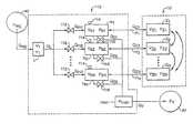
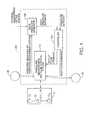
- FIG. 1is an overall functional block diagram that illustrates a pressure control system that regulates pressure in one or more remote zones, in accordance with one embodiment of the description in this disclosure.
- zoneshall mean an enclosed volume.
- a system and methodare described for controlling pressure in remotes zones using an observer-based solution that accurately estimates the pressure of each remote zone whose pressure is to be controlled.
- the closed-loop control performancemay be significantly improved. For example, localized pressure transients that occur in the measurement chamber but do not occur in the remote zone itself may be overcome.
- the pressure control system 100may include a pressure measurement and fluid control system 110 (shown in more detail in FIG. 2 ), a zone pressure estimator 120 , and a controller 130 .
- the pressure control system 100may remotely control pressure in each remote zone Zi, using a zone pressure estimator 120 to estimate the pressure within the remote zone Zi based on the measured pressure inside an enclosure bi (shown in FIG. 2 ) connected to the zone Zi through a conduit Fi (shown in FIG. 2 ), and by controlling flow of a fluid into and out of the enclosure bi based on the estimated pressure from the zone pressure estimator 120 .
- the enclosures bimay be pressure measurement chambers, although any other type of enclosed volume that can enclose the fluid therewithin can be used.
- the pressure measurement and fluid control system 110may include a pressure measurement system, and a fluid control system.
- the pressure measurement system in 110may include, for example, a plurality of pressure sensors 114 (seen in FIG. 2 ), each connected to an enclosure bi, and configured to measure pressure inside the enclosure bi.
- a fluid control system in 110may include a valve system ( 112 and 116 seen in FIG. 2 ) that controls flow rate of fluid into and out of each enclosure bi.
- the zone pressure estimator 120may receive pressure measurements from the pressure measurement system, and may also receive (e.g. from a customer, an operator, or other personnel) physical parameters of the system 100 , which may include, for example, known characteristics of the conduit and the zone.
- the zone pressure estimator 120may further be configured to use the pressure measurements and the physical parameters to calculate and provide pressure estimates for each zone Zi using computational methods described in detail below.
- the controller 130may also receive pressure set points for each of the remote zones Zi, and may use the zone pressure estimates (from the zone pressure estimator 120 ) and the pressure set points to control the fluid control system. In particular, the controller 130 may control the valve system so that the flow rate of the fluid into and out of each enclosure bi is such that pressure within each zone Zi is regulated in accordance with the pressure set points.
- the valve systemmay include, for each enclosure bi, at least one an inlet proportional valve 112 configured to regulate an input flow rate of the fluid into the enclosure bi, and an outlet proportional valve 116 configured to regulate an output flow rate of the fluid out of the enclosure bi.
- the controller 130may be configured to regulate pressure within each zone Zi by operating the inlet proportional valve 112 and the outlet proportional valve 116 so as to control the input flow rate and the output flow rate as a function of the estimated pressure from the zone pressure estimator 120 and of a pressure set point.
- the controller 130may send an input flow command signal an output flow command signal to the valve system within block 110 (described in more detail in FIG. 2 ), so as to control the input flow rate and the output flow rate according to the input flow command signal and the output flow command signal, respectively.
- the controllermay be configured to effect PI (Proportional-Integral) control (described in more detail below) of the input flow rate and the output flow rate into and out of each enclosure, although other control methods may also be used.
- PIProportional-Integral
- control system 100 and methodis described as a proportional-plus-integral (PI) type control system and method, many other types of control systems and methods can be used, including but not limited to proportional, integral, proportional-plus-derivative (PD), and proportional-plus-integral-plus-derivative (PID) types of feedback control systems and methods.
- PIproportional-plus-integral
- PDproportional-plus-derivative
- PIDproportional-plus-integral-plus-derivative
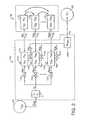
- FIG. 2also illustrates a pressure measurement and fluid control system used in one embodiment of the pressure control system 100 described in this disclosure.
- Each measurement chamber b iincludes an inlet valve 112 configured to regulate input flow rate of the fluid into b i , and an outlet valve 116 configured to regulate output flow rate of the fluid out of b i .
- Each measurement chamber b iis located along a fluid flow line that goes from the pressurized fluid source 40 through an inlet manifold “L” into the inlet valve 112 for the enclosure b i , and out of the outlet valve 116 for the enclosure b i through a flow constrictor manifold (shown as “man” in FIG. 2 ) to the vacuum exhaust 30 .
- a pressure sensor 114(typically a transducer) is operatively connected to each measurement chamber b j to measure the pressure within b i .
- the flow constrictor manifoldmay be a venturi manifold, although other types of flow constrictors may also be used.
- the remote zones Zi(shown inside block 10 in FIG. 2 ) may have rigid or flexible walls, and may be coupled or non-coupled.
- the remote zones Zi with flexible wallsmay have volumes that can expand and contract. The volumes of the zones Zi with flexible walls may interact with each other, e.g. push against each other.
- the coupling between the various zones Zimay occur in a number of ways.
- Volumetric coupling at a zone Zi that has walls that are flexible (and thus can expand and contract)may occur due to volume expansion/contraction and volume-to-volume interaction.
- the interactionmay occur, for example, by one zone Zi expanding and pushing against another zone Zi thereby increasing pressure within the second zone Zi.
- Outlet coupling at the exhaustmay occur if the vacuum pressure level drifts, cause outlet flows to change, and in extreme cases results in flows transitioning between choked and unchoked. This may be especially critical in the case of a venturi pump with high flow being dumped into the venturi line.
- the zone Zi wallsmay be rigid or flexible.
- Inlet couplingmay occur if the set point in one zone Zi is set sufficiently high such that there is a significant in-rush of flow into its manifold, resulting in a drop of line pressure, i.e. transient behavior.
- This line pressure dropmay affect all the other zones Zi fed by the source.
- the zone Zi wallsmay be rigid or flexible.
- a system with only one zone and rigid wallsmay be considered as a “non-coupled, single-zone system.” Multiple instances of such a rigid zone that are fed by independent inlets and that dump into independent exhausts may be an example of a “non-coupled, multi-zone system.”
- a single zone with flexible walls that can expand or contractmay be considered to be a “coupled, single-zone system.”
- the illustrative embodiments shown in FIGS. 1 and 2may be a “coupled, multi-zone systems,” in which the level of coupling may be quantified based on inlet, outlet, and volumetric coupling.
- the zone pressure estimator 120may estimate the pressure in each of the zones Zi by using the pressure measurements of the pressure sensors 114 , the physical parameters of each enclosure bi (e.g. measurement chamber) and each zone Zi, and a model-based algorithm (described below) to accurately estimate the pressure of the zones Zi.
- a pressure control systemthat uses the zone pressure estimator 120 in a closed loop for controlling the pressure in the zones Zi may overcome localized pressure transients in the measurement chambers that may not occur in the zones Zi themselves. In this way, the closed-loop control performance of the pressure control system 100 may significantly improve.
- the zone pressure estimator 120may easily integrate into an advanced control system, and may compensates for multiple zones Z i that exhibit static and/or dynamic coupling of inlet pressure/flow, outlet pressure/flow, and zone volume interaction.
- the zone pressure estimator 120places no restrictions on the size or volumes of the remotes zones Z i .
- the zone pressure estimator 120is valid for different ranges of pressure set points and, when incorporated into an advanced control system, will ensure consistent transient and steady-state behavior.
- the controller 130is configured to receive the pressure set point for each of the i zones, receive the zone pressure estimate for each of the i zones from the zone pressure estimator 120 , and to regulate the pressure in each zone in accordance with pressure set point by operating the inlet and outlet proportional valves 112 , 116 by controlling the flow of the fluid into and out of the measuring chamber bi connected to zone i.
- the controller 130may send an input flow command signal to the inlet proportional valve 112 of enclosure bi and an output flow command signal to the output proportional valve 116 of enclosure bi so as to control the input flow rate into enclosure i and the output flow rate out of enclosure bi according to the input flow command signal and the output flow command signal, respectively.
- the controllermay effect PI control of the input flow rate and the output flow rate, although other types of proportional valve control may also be used.
- Q in,idenotes the input flow rate into enclosure i
- Q out,idenotes the output flow rate out of enclosure b i
- ⁇ Pindenotes a proportional gain for the input flow rate
- ⁇ Iindenotes an integral gain for the input flow rate
- ⁇ Poutdenotes a proportional gain for the output flow rate
- ⁇ Ioutdenotes an integral gain for the output flow rate
- P z,idenotes the estimated pressure within the zone Z i
- P tdenotes a desired pressure trajectory from one pressure setpoint to another pressure setpoint
- P t ⁇ P z,idenotes a tracking error.
- the pressure trajectories P tmay be constructed using a number of techniques, including but not limited to polynomials, and solutions of first or higher order differential equations.
- model-based computational methodused to operate the zone pressure estimator 120 to estimate the pressure in each zone Zi is described below.
- This model-based computational methodmay be based upon the dynamics of the measurement chambers, as well as the dynamics and volumetric coupling of the remote zones Zi, described below.
- P b,iis the pressure measured by the pressure transducer 114 in the measurement chamber for the i th zone
- P STPis the pressure at standard temperature and pressure (STP) conditions
- Q in,idenotes the input flow
- Q o,i and Q z,idenote the output flows.
- Q o,iis the flow from the i th measurement chamber b i to the venturi manifold
- Q z,iis the flow to the i th zone.
- V b,idenotes the volume of the measurement chamber b i for the i th zone.
- d orifice,idenotes the diameter of the fixed orifice in the measurement chamber that feeds the venturi manifold and P man denotes the pressure in the venturi manifold connected to the vacuum exhaust 30 .
- the flow through the orificemay be choked or unchoked depending on the pressure differential across the fixed orifice.
- C tube,i and ⁇ tube,iare constants associated with the conduit F i that connects the measurement chamber b i to the zone Z i .
- C tube,irepresents a conductance of the conduit F i , in SI units [(m 3 /s)/(s-Pa)] and ⁇ tube,i representing a flow equilibration time constant across the conduit, also in SI units.
- V z0,iis the initial volume of each zone under standard temperature and pressure (STP) conditions
- ⁇ Vis the volume expansion/contraction time constant
- ⁇ iirepresents the expansion/contraction coefficient
- ⁇ ijrepresents the coupling coefficient between zone i and zone j.
- the control objective for the controller 130is to regulate the pressures within the remote zones Z i .
- the pressure transducer 114 for b iis housed in the measurement chamber b i , as opposed to in the zone Z i .
- the measurement chambers b iare separated from the remote zones Z i by conduits F i .
- the observer-based model for the pressure control algorithmmay be developed in a number of ways.
- a flow sensore.g., an anemometer, thermal-based sensor, pressure-based sensor, etc.
- Another approachmay be to develop an intermediate flow observer by rewriting the zone flow equation in its discrete form:
- ⁇ ⁇ V ⁇ z , i ( n )⁇ V ⁇ z , i ( n - 1 ) + ⁇ ⁇ ⁇ t ⁇ v [ V z0 , i + ⁇ ii ⁇ ( P ⁇ z , i ( n - 1 ) - P STP ) + ⁇ i ⁇ j ⁇ ⁇ ⁇ ij ⁇ ( P ⁇ z , i ( n - 1 ) - P ⁇ z , j ( n - 1 ) ) ] ( 1 + ⁇ ⁇ ⁇ t ⁇ v ) ( 7 )
- ⁇ ⁇ P ⁇ z , i ( n )⁇ P ⁇ z , i ( n - 1 ) + ⁇ ⁇ ⁇ ⁇ t ⁇ ( P STP V ⁇ z , i ( n ) ⁇ Q ⁇ z , i ( n ) + P ⁇ z , i ( n - 1 ) ⁇ v ⁇ V ⁇ z , i ( n ) [ V ⁇ z , i ( n ) - V z ⁇ 0 , i - ⁇ ii ⁇ ( P ⁇ z , i ( n - 1 ) - P STP ) - ⁇ i ⁇ j ⁇ ⁇ ⁇ ij ⁇ ( P ⁇ z , i ( n - 1 ) - P ⁇ z , j ( n - 1 ) ) ] ) , ( 8
- ⁇ circumflex over (P) ⁇ z,i (n)denotes the nth sample of a pressure estimate of the ith zone
- ⁇ circumflex over (Q) ⁇ z,i (n)is obtained from the flow estimate defined in (6) or can be replaced by the direct flow measurement Q z when available
- ⁇ circumflex over (V) ⁇ z,i (n)is obtained from (7).
Landscapes
- Physics & Mathematics (AREA)
- Fluid Mechanics (AREA)
- General Physics & Mathematics (AREA)
- Engineering & Computer Science (AREA)
- Automation & Control Theory (AREA)
- Control Of Fluid Pressure (AREA)
- Measuring Fluid Pressure (AREA)
Abstract
Description
Qin,i=
Qout,i=
In the above equations, Qin,idenotes the input flow rate into enclosure i, Qout,idenotes the output flow rate out of enclosure bi,
Qo,i=ƒ(Pb,i,Pman,dorifice,i) ∀i=1,2, . . . ,N, (2)
Claims (9)
Qin,i=κPin(P1−Pz,i)+κlin∂(P1−Pz,i)dt;
Qout,i=κPout(P1−Pz,i)+κIout∂(P1−Pz,i)dt; and
Qin,i=κPin(P1−Pz,i)+κlin∂(P1−Pz,i)dt;
Qout,i=κPout(P1−Pz,i)+κIout∂(P1−Pz,i)dt; and
Priority Applications (10)
| Application Number | Priority Date | Filing Date | Title |
|---|---|---|---|
| US11/333,142US8037896B2 (en) | 2004-03-09 | 2006-01-17 | Pressure regulation in remote zones |
| DE112006003678.5TDE112006003678B4 (en) | 2006-01-17 | 2006-11-08 | Pressure regulation in remote zones |
| PCT/US2006/043692WO2007123576A1 (en) | 2006-01-17 | 2006-11-08 | Pressure regulation in remote zones |
| GB0811130AGB2446358B (en) | 2006-01-17 | 2006-11-08 | Pressure regulation in remote zones |
| CNA2006800508421ACN101356481A (en) | 2006-01-17 | 2006-11-08 | Pressure regulation in remote zones |
| JP2008551255AJP2009524147A (en) | 2006-01-17 | 2006-11-08 | Pressure regulation in remote compartment |
| TW96101519ATWI406119B (en) | 2006-01-17 | 2007-01-16 | A system for remotely controlling pressure within a zone and a chemical mechanical polishing machine system |
| KR1020087019811AKR101259779B1 (en) | 2006-01-17 | 2008-08-12 | Pressure regulation within remote zone |
| US13/271,447US8689822B2 (en) | 2004-03-09 | 2011-10-12 | Pressure regulation in remote zones |
| JP2012268442AJP2013065345A (en) | 2006-01-17 | 2012-12-07 | Pressure regulation in remote zone |
Applications Claiming Priority (2)
| Application Number | Priority Date | Filing Date | Title |
|---|---|---|---|
| US10/796,723US6986359B2 (en) | 2004-03-09 | 2004-03-09 | System and method for controlling pressure in remote zones |
| US11/333,142US8037896B2 (en) | 2004-03-09 | 2006-01-17 | Pressure regulation in remote zones |
Related Parent Applications (1)
| Application Number | Title | Priority Date | Filing Date |
|---|---|---|---|
| US10/796,723Continuation-In-PartUS6986359B2 (en) | 2004-03-09 | 2004-03-09 | System and method for controlling pressure in remote zones |
Related Child Applications (1)
| Application Number | Title | Priority Date | Filing Date |
|---|---|---|---|
| US13/271,447DivisionUS8689822B2 (en) | 2004-03-09 | 2011-10-12 | Pressure regulation in remote zones |
Publications (2)
| Publication Number | Publication Date |
|---|---|
| US20060169327A1 US20060169327A1 (en) | 2006-08-03 |
| US8037896B2true US8037896B2 (en) | 2011-10-18 |
Family
ID=37865673
Family Applications (2)
| Application Number | Title | Priority Date | Filing Date |
|---|---|---|---|
| US11/333,142Expired - LifetimeUS8037896B2 (en) | 2004-03-09 | 2006-01-17 | Pressure regulation in remote zones |
| US13/271,447Expired - LifetimeUS8689822B2 (en) | 2004-03-09 | 2011-10-12 | Pressure regulation in remote zones |
Family Applications After (1)
| Application Number | Title | Priority Date | Filing Date |
|---|---|---|---|
| US13/271,447Expired - LifetimeUS8689822B2 (en) | 2004-03-09 | 2011-10-12 | Pressure regulation in remote zones |
Country Status (8)
| Country | Link |
|---|---|
| US (2) | US8037896B2 (en) |
| JP (2) | JP2009524147A (en) |
| KR (1) | KR101259779B1 (en) |
| CN (1) | CN101356481A (en) |
| DE (1) | DE112006003678B4 (en) |
| GB (1) | GB2446358B (en) |
| TW (1) | TWI406119B (en) |
| WO (1) | WO2007123576A1 (en) |
Cited By (3)
| Publication number | Priority date | Publication date | Assignee | Title |
|---|---|---|---|---|
| US20110186144A1 (en)* | 2010-01-29 | 2011-08-04 | Advanced Manufacturing Technology For Bottles, Inc. | Pressurized Fluid Positioner Control System |
| CN111623158A (en)* | 2020-06-07 | 2020-09-04 | 常州市瑾瑜精密科技有限公司 | Valve control system |
| US11320843B2 (en)* | 2019-10-17 | 2022-05-03 | Dongguan Hesheng Machinery & Electric Co., Ltd. | Air compression system with pressure detection |
Families Citing this family (119)
| Publication number | Priority date | Publication date | Assignee | Title |
|---|---|---|---|---|
| JP5082989B2 (en)* | 2008-03-31 | 2012-11-28 | 日立金属株式会社 | Flow control device, verification method thereof, and flow control method |
| US8302420B2 (en)* | 2009-04-27 | 2012-11-06 | Hermes Microvision, Inc. | Method for venting gas into closed space and gas supply assembly thereof |
| US8783027B2 (en)* | 2009-09-18 | 2014-07-22 | Siemens Energy, Inc. | Pressure regulation circuit for turbine generators |
| GB2474892B (en)* | 2009-10-30 | 2011-09-21 | Siemens Vai Metals Tech Ltd | Flow control valve |
| US9127361B2 (en)* | 2009-12-07 | 2015-09-08 | Mks Instruments, Inc. | Methods of and apparatus for controlling pressure in multiple zones of a process tool |
| JP5496771B2 (en)* | 2010-05-13 | 2014-05-21 | 株式会社Kelk | Temperature control method using temperature control device |
| US9324576B2 (en) | 2010-05-27 | 2016-04-26 | Applied Materials, Inc. | Selective etch for silicon films |
| US10283321B2 (en) | 2011-01-18 | 2019-05-07 | Applied Materials, Inc. | Semiconductor processing system and methods using capacitively coupled plasma |
| US8999856B2 (en) | 2011-03-14 | 2015-04-07 | Applied Materials, Inc. | Methods for etch of sin films |
| US9064815B2 (en) | 2011-03-14 | 2015-06-23 | Applied Materials, Inc. | Methods for etch of metal and metal-oxide films |
| US9267739B2 (en) | 2012-07-18 | 2016-02-23 | Applied Materials, Inc. | Pedestal with multi-zone temperature control and multiple purge capabilities |
| US9373517B2 (en) | 2012-08-02 | 2016-06-21 | Applied Materials, Inc. | Semiconductor processing with DC assisted RF power for improved control |
| US9023734B2 (en) | 2012-09-18 | 2015-05-05 | Applied Materials, Inc. | Radical-component oxide etch |
| US9132436B2 (en) | 2012-09-21 | 2015-09-15 | Applied Materials, Inc. | Chemical control features in wafer process equipment |
| US8921234B2 (en) | 2012-12-21 | 2014-12-30 | Applied Materials, Inc. | Selective titanium nitride etching |
| US10256079B2 (en) | 2013-02-08 | 2019-04-09 | Applied Materials, Inc. | Semiconductor processing systems having multiple plasma configurations |
| US9362130B2 (en) | 2013-03-01 | 2016-06-07 | Applied Materials, Inc. | Enhanced etching processes using remote plasma sources |
| US9040422B2 (en) | 2013-03-05 | 2015-05-26 | Applied Materials, Inc. | Selective titanium nitride removal |
| US20140271097A1 (en) | 2013-03-15 | 2014-09-18 | Applied Materials, Inc. | Processing systems and methods for halide scavenging |
| US20140311581A1 (en)* | 2013-04-19 | 2014-10-23 | Applied Materials, Inc. | Pressure controller configuration for semiconductor processing applications |
| US9493879B2 (en) | 2013-07-12 | 2016-11-15 | Applied Materials, Inc. | Selective sputtering for pattern transfer |
| US9773648B2 (en) | 2013-08-30 | 2017-09-26 | Applied Materials, Inc. | Dual discharge modes operation for remote plasma |
| US9576809B2 (en) | 2013-11-04 | 2017-02-21 | Applied Materials, Inc. | Etch suppression with germanium |
| US9520303B2 (en) | 2013-11-12 | 2016-12-13 | Applied Materials, Inc. | Aluminum selective etch |
| US9245762B2 (en) | 2013-12-02 | 2016-01-26 | Applied Materials, Inc. | Procedure for etch rate consistency |
| US9499898B2 (en) | 2014-03-03 | 2016-11-22 | Applied Materials, Inc. | Layered thin film heater and method of fabrication |
| US9299537B2 (en) | 2014-03-20 | 2016-03-29 | Applied Materials, Inc. | Radial waveguide systems and methods for post-match control of microwaves |
| US9903020B2 (en) | 2014-03-31 | 2018-02-27 | Applied Materials, Inc. | Generation of compact alumina passivation layers on aluminum plasma equipment components |
| US9309598B2 (en) | 2014-05-28 | 2016-04-12 | Applied Materials, Inc. | Oxide and metal removal |
| US9425058B2 (en) | 2014-07-24 | 2016-08-23 | Applied Materials, Inc. | Simplified litho-etch-litho-etch process |
| US9496167B2 (en) | 2014-07-31 | 2016-11-15 | Applied Materials, Inc. | Integrated bit-line airgap formation and gate stack post clean |
| US9659753B2 (en) | 2014-08-07 | 2017-05-23 | Applied Materials, Inc. | Grooved insulator to reduce leakage current |
| US9553102B2 (en) | 2014-08-19 | 2017-01-24 | Applied Materials, Inc. | Tungsten separation |
| US9355862B2 (en) | 2014-09-24 | 2016-05-31 | Applied Materials, Inc. | Fluorine-based hardmask removal |
| US9613822B2 (en) | 2014-09-25 | 2017-04-04 | Applied Materials, Inc. | Oxide etch selectivity enhancement |
| US9355922B2 (en) | 2014-10-14 | 2016-05-31 | Applied Materials, Inc. | Systems and methods for internal surface conditioning in plasma processing equipment |
| US9966240B2 (en) | 2014-10-14 | 2018-05-08 | Applied Materials, Inc. | Systems and methods for internal surface conditioning assessment in plasma processing equipment |
| US11637002B2 (en) | 2014-11-26 | 2023-04-25 | Applied Materials, Inc. | Methods and systems to enhance process uniformity |
| US10573496B2 (en) | 2014-12-09 | 2020-02-25 | Applied Materials, Inc. | Direct outlet toroidal plasma source |
| US10224210B2 (en) | 2014-12-09 | 2019-03-05 | Applied Materials, Inc. | Plasma processing system with direct outlet toroidal plasma source |
| US9502258B2 (en) | 2014-12-23 | 2016-11-22 | Applied Materials, Inc. | Anisotropic gap etch |
| US11257693B2 (en) | 2015-01-09 | 2022-02-22 | Applied Materials, Inc. | Methods and systems to improve pedestal temperature control |
| US9449846B2 (en) | 2015-01-28 | 2016-09-20 | Applied Materials, Inc. | Vertical gate separation |
| US20160225652A1 (en) | 2015-02-03 | 2016-08-04 | Applied Materials, Inc. | Low temperature chuck for plasma processing systems |
| US9728437B2 (en) | 2015-02-03 | 2017-08-08 | Applied Materials, Inc. | High temperature chuck for plasma processing systems |
| US9881805B2 (en) | 2015-03-02 | 2018-01-30 | Applied Materials, Inc. | Silicon selective removal |
| US9691645B2 (en) | 2015-08-06 | 2017-06-27 | Applied Materials, Inc. | Bolted wafer chuck thermal management systems and methods for wafer processing systems |
| US9741593B2 (en) | 2015-08-06 | 2017-08-22 | Applied Materials, Inc. | Thermal management systems and methods for wafer processing systems |
| US9349605B1 (en) | 2015-08-07 | 2016-05-24 | Applied Materials, Inc. | Oxide etch selectivity systems and methods |
| US10504700B2 (en) | 2015-08-27 | 2019-12-10 | Applied Materials, Inc. | Plasma etching systems and methods with secondary plasma injection |
| US10522371B2 (en) | 2016-05-19 | 2019-12-31 | Applied Materials, Inc. | Systems and methods for improved semiconductor etching and component protection |
| US10504754B2 (en) | 2016-05-19 | 2019-12-10 | Applied Materials, Inc. | Systems and methods for improved semiconductor etching and component protection |
| US9865484B1 (en) | 2016-06-29 | 2018-01-09 | Applied Materials, Inc. | Selective etch using material modification and RF pulsing |
| US10062575B2 (en) | 2016-09-09 | 2018-08-28 | Applied Materials, Inc. | Poly directional etch by oxidation |
| US10629473B2 (en) | 2016-09-09 | 2020-04-21 | Applied Materials, Inc. | Footing removal for nitride spacer |
| US9721789B1 (en) | 2016-10-04 | 2017-08-01 | Applied Materials, Inc. | Saving ion-damaged spacers |
| US9934942B1 (en) | 2016-10-04 | 2018-04-03 | Applied Materials, Inc. | Chamber with flow-through source |
| US10546729B2 (en) | 2016-10-04 | 2020-01-28 | Applied Materials, Inc. | Dual-channel showerhead with improved profile |
| US10062585B2 (en) | 2016-10-04 | 2018-08-28 | Applied Materials, Inc. | Oxygen compatible plasma source |
| US10062579B2 (en) | 2016-10-07 | 2018-08-28 | Applied Materials, Inc. | Selective SiN lateral recess |
| US9947549B1 (en) | 2016-10-10 | 2018-04-17 | Applied Materials, Inc. | Cobalt-containing material removal |
| US9768034B1 (en) | 2016-11-11 | 2017-09-19 | Applied Materials, Inc. | Removal methods for high aspect ratio structures |
| US10163696B2 (en) | 2016-11-11 | 2018-12-25 | Applied Materials, Inc. | Selective cobalt removal for bottom up gapfill |
| US10242908B2 (en) | 2016-11-14 | 2019-03-26 | Applied Materials, Inc. | Airgap formation with damage-free copper |
| US10026621B2 (en) | 2016-11-14 | 2018-07-17 | Applied Materials, Inc. | SiN spacer profile patterning |
| US10566206B2 (en) | 2016-12-27 | 2020-02-18 | Applied Materials, Inc. | Systems and methods for anisotropic material breakthrough |
| US10403507B2 (en) | 2017-02-03 | 2019-09-03 | Applied Materials, Inc. | Shaped etch profile with oxidation |
| US10431429B2 (en) | 2017-02-03 | 2019-10-01 | Applied Materials, Inc. | Systems and methods for radial and azimuthal control of plasma uniformity |
| US10043684B1 (en) | 2017-02-06 | 2018-08-07 | Applied Materials, Inc. | Self-limiting atomic thermal etching systems and methods |
| US10319739B2 (en) | 2017-02-08 | 2019-06-11 | Applied Materials, Inc. | Accommodating imperfectly aligned memory holes |
| US10943834B2 (en) | 2017-03-13 | 2021-03-09 | Applied Materials, Inc. | Replacement contact process |
| US10794613B2 (en) | 2017-03-13 | 2020-10-06 | Kevin Michael Murphy, Llc | Overflow protection and monitoring apparatus and methods of installing same |
| US10319649B2 (en) | 2017-04-11 | 2019-06-11 | Applied Materials, Inc. | Optical emission spectroscopy (OES) for remote plasma monitoring |
| US11276559B2 (en) | 2017-05-17 | 2022-03-15 | Applied Materials, Inc. | Semiconductor processing chamber for multiple precursor flow |
| US11276590B2 (en) | 2017-05-17 | 2022-03-15 | Applied Materials, Inc. | Multi-zone semiconductor substrate supports |
| JP7176860B6 (en) | 2017-05-17 | 2022-12-16 | アプライド マテリアルズ インコーポレイテッド | Semiconductor processing chamber to improve precursor flow |
| US10497579B2 (en) | 2017-05-31 | 2019-12-03 | Applied Materials, Inc. | Water-free etching methods |
| US10049891B1 (en) | 2017-05-31 | 2018-08-14 | Applied Materials, Inc. | Selective in situ cobalt residue removal |
| US10920320B2 (en) | 2017-06-16 | 2021-02-16 | Applied Materials, Inc. | Plasma health determination in semiconductor substrate processing reactors |
| US10541246B2 (en) | 2017-06-26 | 2020-01-21 | Applied Materials, Inc. | 3D flash memory cells which discourage cross-cell electrical tunneling |
| US10727080B2 (en) | 2017-07-07 | 2020-07-28 | Applied Materials, Inc. | Tantalum-containing material removal |
| US10541184B2 (en) | 2017-07-11 | 2020-01-21 | Applied Materials, Inc. | Optical emission spectroscopic techniques for monitoring etching |
| US10354889B2 (en) | 2017-07-17 | 2019-07-16 | Applied Materials, Inc. | Non-halogen etching of silicon-containing materials |
| US10170336B1 (en) | 2017-08-04 | 2019-01-01 | Applied Materials, Inc. | Methods for anisotropic control of selective silicon removal |
| US10043674B1 (en) | 2017-08-04 | 2018-08-07 | Applied Materials, Inc. | Germanium etching systems and methods |
| US10297458B2 (en) | 2017-08-07 | 2019-05-21 | Applied Materials, Inc. | Process window widening using coated parts in plasma etch processes |
| US10283324B1 (en) | 2017-10-24 | 2019-05-07 | Applied Materials, Inc. | Oxygen treatment for nitride etching |
| US10128086B1 (en) | 2017-10-24 | 2018-11-13 | Applied Materials, Inc. | Silicon pretreatment for nitride removal |
| US10256112B1 (en) | 2017-12-08 | 2019-04-09 | Applied Materials, Inc. | Selective tungsten removal |
| US10903054B2 (en) | 2017-12-19 | 2021-01-26 | Applied Materials, Inc. | Multi-zone gas distribution systems and methods |
| US11328909B2 (en) | 2017-12-22 | 2022-05-10 | Applied Materials, Inc. | Chamber conditioning and removal processes |
| US10854426B2 (en) | 2018-01-08 | 2020-12-01 | Applied Materials, Inc. | Metal recess for semiconductor structures |
| US10679870B2 (en) | 2018-02-15 | 2020-06-09 | Applied Materials, Inc. | Semiconductor processing chamber multistage mixing apparatus |
| US10964512B2 (en) | 2018-02-15 | 2021-03-30 | Applied Materials, Inc. | Semiconductor processing chamber multistage mixing apparatus and methods |
| TWI766433B (en) | 2018-02-28 | 2022-06-01 | 美商應用材料股份有限公司 | Systems and methods to form airgaps |
| US10593560B2 (en) | 2018-03-01 | 2020-03-17 | Applied Materials, Inc. | Magnetic induction plasma source for semiconductor processes and equipment |
| US10319600B1 (en) | 2018-03-12 | 2019-06-11 | Applied Materials, Inc. | Thermal silicon etch |
| US10497573B2 (en) | 2018-03-13 | 2019-12-03 | Applied Materials, Inc. | Selective atomic layer etching of semiconductor materials |
| US10573527B2 (en) | 2018-04-06 | 2020-02-25 | Applied Materials, Inc. | Gas-phase selective etching systems and methods |
| US10490406B2 (en) | 2018-04-10 | 2019-11-26 | Appled Materials, Inc. | Systems and methods for material breakthrough |
| US10699879B2 (en) | 2018-04-17 | 2020-06-30 | Applied Materials, Inc. | Two piece electrode assembly with gap for plasma control |
| US10886137B2 (en) | 2018-04-30 | 2021-01-05 | Applied Materials, Inc. | Selective nitride removal |
| JP7068062B2 (en)* | 2018-06-18 | 2022-05-16 | 株式会社堀場製作所 | Fluid control device and flow rate control device |
| US10872778B2 (en) | 2018-07-06 | 2020-12-22 | Applied Materials, Inc. | Systems and methods utilizing solid-phase etchants |
| US10755941B2 (en) | 2018-07-06 | 2020-08-25 | Applied Materials, Inc. | Self-limiting selective etching systems and methods |
| US10672642B2 (en) | 2018-07-24 | 2020-06-02 | Applied Materials, Inc. | Systems and methods for pedestal configuration |
| US11049755B2 (en) | 2018-09-14 | 2021-06-29 | Applied Materials, Inc. | Semiconductor substrate supports with embedded RF shield |
| US10892198B2 (en) | 2018-09-14 | 2021-01-12 | Applied Materials, Inc. | Systems and methods for improved performance in semiconductor processing |
| US11062887B2 (en) | 2018-09-17 | 2021-07-13 | Applied Materials, Inc. | High temperature RF heater pedestals |
| US11417534B2 (en) | 2018-09-21 | 2022-08-16 | Applied Materials, Inc. | Selective material removal |
| US11682560B2 (en) | 2018-10-11 | 2023-06-20 | Applied Materials, Inc. | Systems and methods for hafnium-containing film removal |
| US11121002B2 (en) | 2018-10-24 | 2021-09-14 | Applied Materials, Inc. | Systems and methods for etching metals and metal derivatives |
| US11437242B2 (en) | 2018-11-27 | 2022-09-06 | Applied Materials, Inc. | Selective removal of silicon-containing materials |
| US11721527B2 (en) | 2019-01-07 | 2023-08-08 | Applied Materials, Inc. | Processing chamber mixing systems |
| US10920319B2 (en) | 2019-01-11 | 2021-02-16 | Applied Materials, Inc. | Ceramic showerheads with conductive electrodes |
| DE102019106682B4 (en)* | 2019-03-15 | 2022-07-07 | Bürkert Werke GmbH & Co. KG | pressure regulator |
| JP7602350B2 (en)* | 2020-11-11 | 2024-12-18 | 株式会社堀場エステック | Concentration control system, concentration control method, and program for concentration control system |
| JP7535469B2 (en)* | 2020-11-24 | 2024-08-16 | 株式会社堀場エステック | Flow control device, flow control method, and program for flow control device |
| TWI785608B (en)* | 2021-05-12 | 2022-12-01 | 復盛股份有限公司 | Fluid machinery and control method thereof |
Citations (18)
| Publication number | Priority date | Publication date | Assignee | Title |
|---|---|---|---|---|
| US4456038A (en)* | 1981-03-25 | 1984-06-26 | Hennessy Industries, Inc. | Apparatus for pressurizing tires to a desired level |
| US4961441A (en)* | 1989-11-13 | 1990-10-09 | Salter Stuart C | Method and system for controlling a pressure regulator |
| US5325884A (en)* | 1991-07-10 | 1994-07-05 | Conservair Technologies | Compressed air control system |
| US5443087A (en)* | 1993-12-13 | 1995-08-22 | Melea Limited | Method and system for controlling a pressurized fluid and valve assembly for use therein |
| US5551770A (en) | 1994-10-27 | 1996-09-03 | Ford Motor Company | Method for estimating pressure in a pressure actuated controller |
| EP0847835A1 (en) | 1996-12-12 | 1998-06-17 | Wacker Siltronic Gesellschaft für Halbleitermaterialien Aktiengesellschaft | Method and apparatus for polishing semiconductor substrates |
| US5840060A (en)* | 1991-08-21 | 1998-11-24 | Smith & Nephew, Inc. | Fluid management system |
| US5916016A (en) | 1997-10-23 | 1999-06-29 | Vlsi Technology, Inc. | Methods and apparatus for polishing wafers |
| US5964653A (en) | 1997-07-11 | 1999-10-12 | Applied Materials, Inc. | Carrier head with a flexible membrane for a chemical mechanical polishing system |
| US6277009B1 (en) | 1997-12-31 | 2001-08-21 | Applied Materials, Inc. | Carrier head including a flexible membrane and a compliant backing member for a chemical mechanical polishing apparatus |
| US6435956B1 (en) | 1999-02-02 | 2002-08-20 | Ebara Corporation | Wafer holder and polishing device |
| US20020142704A1 (en)* | 2001-03-28 | 2002-10-03 | Taiwan Semiconductor Manufacturing Co., Ltd. | Linear chemical mechanical polishing apparatus equipped with programmable pneumatic support platen and method of using |
| US6506105B1 (en) | 2000-05-12 | 2003-01-14 | Multi-Planar Technologies, Inc. | System and method for pneumatic diaphragm CMP head having separate retaining ring and multi-region wafer pressure control |
| US6722946B2 (en)* | 2002-01-17 | 2004-04-20 | Nutool, Inc. | Advanced chemical mechanical polishing system with smart endpoint detection |
| US20040118403A1 (en) | 2000-12-29 | 2004-06-24 | O'connor Gerard Michael | Characterisation of mask systems |
| US6758233B2 (en)* | 2000-02-09 | 2004-07-06 | Saskatchewan Research Council | High volume electronic gas regulator |
| US20050189018A1 (en)* | 2004-02-12 | 2005-09-01 | Brodeur Craig L. | System and method for flow monitoring and control |
| US20050199287A1 (en) | 2004-03-09 | 2005-09-15 | Ali Shajii | System and method for controlling pressure in remote zones |
Family Cites Families (11)
| Publication number | Priority date | Publication date | Assignee | Title |
|---|---|---|---|---|
| JPS61170633A (en) | 1985-01-24 | 1986-08-01 | Mitsui Eng & Shipbuild Co Ltd | Pressure control device for cavitation tank |
| US5762539A (en) | 1996-02-27 | 1998-06-09 | Ebara Corporation | Apparatus for and method for polishing workpiece |
| US5957751A (en) | 1997-05-23 | 1999-09-28 | Applied Materials, Inc. | Carrier head with a substrate detection mechanism for a chemical mechanical polishing system |
| US6368189B1 (en) | 1999-03-03 | 2002-04-09 | Mitsubishi Materials Corporation | Apparatus and method for chemical-mechanical polishing (CMP) head having direct pneumatic wafer polishing pressure |
| DE19956553B4 (en) | 1999-11-24 | 2010-11-25 | Robert Bosch Gmbh | Method for estimating the pressure in a wheel brake cylinder and control unit for carrying out the method |
| US6439956B1 (en)* | 2000-11-13 | 2002-08-27 | Interact Accessories, Inc. | RC car device |
| US6568416B2 (en)* | 2001-02-28 | 2003-05-27 | Brian L. Andersen | Fluid flow control system, fluid delivery and control system for a fluid delivery line, and method for controlling pressure oscillations within fluid of a fluid delivery line |
| US6766260B2 (en) | 2002-01-04 | 2004-07-20 | Mks Instruments, Inc. | Mass flow ratio system and method |
| SG144762A1 (en) | 2002-07-19 | 2008-08-28 | Entegris Inc | Fluid flow measuring and proportional fluid flow control device |
| CN100374768C (en)* | 2002-07-19 | 2008-03-12 | 诚实公司 | Liquid flow control apparatus and method |
| JP2004090744A (en) | 2002-08-30 | 2004-03-25 | Hitachi Unisia Automotive Ltd | Brake pressure estimation device |
- 2006
- 2006-01-17USUS11/333,142patent/US8037896B2/ennot_activeExpired - Lifetime
- 2006-11-08WOPCT/US2006/043692patent/WO2007123576A1/enactiveApplication Filing
- 2006-11-08DEDE112006003678.5Tpatent/DE112006003678B4/ennot_activeExpired - Fee Related
- 2006-11-08JPJP2008551255Apatent/JP2009524147A/enactivePending
- 2006-11-08GBGB0811130Apatent/GB2446358B/ennot_activeExpired - Fee Related
- 2006-11-08CNCNA2006800508421Apatent/CN101356481A/enactivePending
- 2007
- 2007-01-16TWTW96101519Apatent/TWI406119B/ennot_activeIP Right Cessation
- 2008
- 2008-08-12KRKR1020087019811Apatent/KR101259779B1/ennot_activeExpired - Fee Related
- 2011
- 2011-10-12USUS13/271,447patent/US8689822B2/ennot_activeExpired - Lifetime
- 2012
- 2012-12-07JPJP2012268442Apatent/JP2013065345A/enactivePending
Patent Citations (19)
| Publication number | Priority date | Publication date | Assignee | Title |
|---|---|---|---|---|
| US4456038A (en)* | 1981-03-25 | 1984-06-26 | Hennessy Industries, Inc. | Apparatus for pressurizing tires to a desired level |
| US4961441A (en)* | 1989-11-13 | 1990-10-09 | Salter Stuart C | Method and system for controlling a pressure regulator |
| US5325884A (en)* | 1991-07-10 | 1994-07-05 | Conservair Technologies | Compressed air control system |
| US5840060A (en)* | 1991-08-21 | 1998-11-24 | Smith & Nephew, Inc. | Fluid management system |
| US5443087A (en)* | 1993-12-13 | 1995-08-22 | Melea Limited | Method and system for controlling a pressurized fluid and valve assembly for use therein |
| US5551770A (en) | 1994-10-27 | 1996-09-03 | Ford Motor Company | Method for estimating pressure in a pressure actuated controller |
| EP0847835A1 (en) | 1996-12-12 | 1998-06-17 | Wacker Siltronic Gesellschaft für Halbleitermaterialien Aktiengesellschaft | Method and apparatus for polishing semiconductor substrates |
| US5980361A (en) | 1996-12-12 | 1999-11-09 | Wacker Siltronic Gesellschaft Fur Halbleitermaterialien Ag | Method and device for polishing semiconductor wafers |
| US5964653A (en) | 1997-07-11 | 1999-10-12 | Applied Materials, Inc. | Carrier head with a flexible membrane for a chemical mechanical polishing system |
| US5916016A (en) | 1997-10-23 | 1999-06-29 | Vlsi Technology, Inc. | Methods and apparatus for polishing wafers |
| US6277009B1 (en) | 1997-12-31 | 2001-08-21 | Applied Materials, Inc. | Carrier head including a flexible membrane and a compliant backing member for a chemical mechanical polishing apparatus |
| US6435956B1 (en) | 1999-02-02 | 2002-08-20 | Ebara Corporation | Wafer holder and polishing device |
| US6758233B2 (en)* | 2000-02-09 | 2004-07-06 | Saskatchewan Research Council | High volume electronic gas regulator |
| US6506105B1 (en) | 2000-05-12 | 2003-01-14 | Multi-Planar Technologies, Inc. | System and method for pneumatic diaphragm CMP head having separate retaining ring and multi-region wafer pressure control |
| US20040118403A1 (en) | 2000-12-29 | 2004-06-24 | O'connor Gerard Michael | Characterisation of mask systems |
| US20020142704A1 (en)* | 2001-03-28 | 2002-10-03 | Taiwan Semiconductor Manufacturing Co., Ltd. | Linear chemical mechanical polishing apparatus equipped with programmable pneumatic support platen and method of using |
| US6722946B2 (en)* | 2002-01-17 | 2004-04-20 | Nutool, Inc. | Advanced chemical mechanical polishing system with smart endpoint detection |
| US20050189018A1 (en)* | 2004-02-12 | 2005-09-01 | Brodeur Craig L. | System and method for flow monitoring and control |
| US20050199287A1 (en) | 2004-03-09 | 2005-09-15 | Ali Shajii | System and method for controlling pressure in remote zones |
Non-Patent Citations (5)
| Title |
|---|
| Examination Report received in corresponding Great Britain Application No. GB0811130.4 dated Aug. 2, 2010. |
| Notification of Grant from related United Kingdom Patent Application No. GB0811130.4, dated Apr. 5, 2011, 2 pages. |
| PCT International Search Report for related PCT Application No. PCT/US2006/043692 (4 pages). |
| PCT Written Opinion of the International Searching Authority for related PCT Application No. PCT/US2006/043692 (8 pages). |
| The Response filed to the Examination Report in related United Kingdom Patent Application No. GB0811130.4, dated Feb. 1, 2011. |
Cited By (4)
| Publication number | Priority date | Publication date | Assignee | Title |
|---|---|---|---|---|
| US20110186144A1 (en)* | 2010-01-29 | 2011-08-04 | Advanced Manufacturing Technology For Bottles, Inc. | Pressurized Fluid Positioner Control System |
| US8347920B2 (en)* | 2010-01-29 | 2013-01-08 | Flexibility Engineering, Llc | Pressurized fluid positioner control system |
| US11320843B2 (en)* | 2019-10-17 | 2022-05-03 | Dongguan Hesheng Machinery & Electric Co., Ltd. | Air compression system with pressure detection |
| CN111623158A (en)* | 2020-06-07 | 2020-09-04 | 常州市瑾瑜精密科技有限公司 | Valve control system |
Also Published As
| Publication number | Publication date |
|---|---|
| US8689822B2 (en) | 2014-04-08 |
| DE112006003678B4 (en) | 2017-05-11 |
| GB2446358B (en) | 2011-05-04 |
| US20120202408A1 (en) | 2012-08-09 |
| KR20080083713A (en) | 2008-09-18 |
| US20060169327A1 (en) | 2006-08-03 |
| KR101259779B1 (en) | 2013-05-03 |
| DE112006003678T5 (en) | 2008-12-11 |
| WO2007123576A1 (en) | 2007-11-01 |
| JP2013065345A (en) | 2013-04-11 |
| GB0811130D0 (en) | 2008-07-23 |
| CN101356481A (en) | 2009-01-28 |
| JP2009524147A (en) | 2009-06-25 |
| TW200745804A (en) | 2007-12-16 |
| TWI406119B (en) | 2013-08-21 |
| GB2446358A (en) | 2008-08-06 |
Similar Documents
| Publication | Publication Date | Title |
|---|---|---|
| US8037896B2 (en) | Pressure regulation in remote zones | |
| US10801867B2 (en) | Method and apparatus for self verification of pressured based mass flow controllers | |
| KR100427563B1 (en) | Parallel bypass type fluid feeding device, and method and device for controlling fluid variable type pressure system flow rate used for the device | |
| US8316879B2 (en) | Method and device for controlling pressure of vacuum container | |
| US9864383B2 (en) | Method and system for determining characteristic parameters of a hydraulic network | |
| US7204155B2 (en) | Method and apparatus for pressure control and flow measurement | |
| EP2089679B1 (en) | Controller gain scheduling for mass flow controllers | |
| US7621290B2 (en) | Gas delivery method and system including a flow ratio controller using antisymmetric optimal control | |
| CN100407083C (en) | Flow Measurement Modules and Methods | |
| US7673645B2 (en) | Gas delivery method and system including a flow ratio controller using a multiple antisymmetric optimal control arrangement | |
| JP5665794B2 (en) | Gas shunt supply device for semiconductor manufacturing equipment | |
| KR102755306B1 (en) | Method and device for multi-channel mass flow rate and flow rate control system | |
| WO2001004717A1 (en) | System and method for a variable gain proportional-integral (pi) controller | |
| JP2000077394A (en) | Semiconductor manufacturing equipment | |
| US9523365B2 (en) | Decoupling of controlled variables in a fluid conveying system with dead time | |
| TW201945657A (en) | Flow rate control method and flow rate control device | |
| US20180120864A1 (en) | Nonlinear control of mass flow controller devices using sliding mode | |
| TWI877310B (en) | Methods and apparatus for pressure based mass flow ratio control | |
| JP3387849B2 (en) | Variable fluid flow control method and device using flow factor | |
| JP2024521576A (en) | Method and apparatus for pressure-based mass flow ratio control - Patents.com | |
| KR102584401B1 (en) | Apparatus for controling fluid and method for controling fluid | |
| JP2018513331A (en) | Valve and control method |
Legal Events
| Date | Code | Title | Description |
|---|---|---|---|
| AS | Assignment | Owner name:MKS INSTRUMENTS, INC., MASSACHUSETTS Free format text:ASSIGNMENT OF ASSIGNORS INTEREST;ASSIGNORS:SHAJII, ALI;NAGARKATTI, SIDDHARTH P.;HILL, GORDON;REEL/FRAME:017496/0439 Effective date:20060322 | |
| STCF | Information on status: patent grant | Free format text:PATENTED CASE | |
| FPAY | Fee payment | Year of fee payment:4 | |
| AS | Assignment | Owner name:BARCLAYS BANK PLC, NEW YORK Free format text:SECURITY AGREEMENT;ASSIGNORS:MKS INSTRUMENTS, INC.;NEWPORT CORPORATION;REEL/FRAME:038663/0139 Effective date:20160429 Owner name:DEUTSCHE BANK AG NEW YORK BRANCH, NEW YORK Free format text:SECURITY AGREEMENT;ASSIGNORS:MKS INSTRUMENTS, INC.;NEWPORT CORPORATION;REEL/FRAME:038663/0265 Effective date:20160429 | |
| AS | Assignment | Owner name:BARCLAYS BANK PLC, AS COLLATERAL AGENT, NEW YORK Free format text:PATENT SECURITY AGREEMENT (ABL);ASSIGNORS:ELECTRO SCIENTIFIC INDUSTRIES, INC.;MKS INSTRUMENTS, INC.;NEWPORT CORPORATION;REEL/FRAME:048211/0312 Effective date:20190201 Owner name:MKS INSTRUMENTS, INC., MASSACHUSETTS Free format text:RELEASE BY SECURED PARTY;ASSIGNOR:DEUTSCHE BANK AG NEW YORK BRANCH;REEL/FRAME:048226/0095 Effective date:20190201 Owner name:NEWPORT CORPORATION, CALIFORNIA Free format text:RELEASE BY SECURED PARTY;ASSIGNOR:DEUTSCHE BANK AG NEW YORK BRANCH;REEL/FRAME:048226/0095 Effective date:20190201 | |
| MAFP | Maintenance fee payment | Free format text:PAYMENT OF MAINTENANCE FEE, 8TH YEAR, LARGE ENTITY (ORIGINAL EVENT CODE: M1552); ENTITY STATUS OF PATENT OWNER: LARGE ENTITY Year of fee payment:8 | |
| AS | Assignment | Owner name:BARCLAYS BANK PLC, AS COLLATERAL AGENT, NEW YORK Free format text:CORRECTIVE ASSIGNMENT TO CORRECT THE REMOVE U.S. PATENT NO.7,919,646 PREVIOUSLY RECORDED ON REEL 048211 FRAME 0312. ASSIGNOR(S) HEREBY CONFIRMS THE PATENT SECURITY AGREEMENT (ABL);ASSIGNORS:ELECTRO SCIENTIFIC INDUSTRIES, INC.;MKS INSTRUMENTS, INC.;NEWPORT CORPORATION;REEL/FRAME:055668/0687 Effective date:20190201 | |
| AS | Assignment | Owner name:JPMORGAN CHASE BANK, N.A., AS COLLATERAL AGENT, ILLINOIS Free format text:SECURITY INTEREST;ASSIGNORS:MKS INSTRUMENTS, INC.;NEWPORT CORPORATION;ELECTRO SCIENTIFIC INDUSTRIES, INC.;REEL/FRAME:061572/0069 Effective date:20220817 | |
| AS | Assignment | Owner name:ELECTRO SCIENTIFIC INDUSTRIES, INC., OREGON Free format text:RELEASE BY SECURED PARTY;ASSIGNOR:BARCLAYS BANK PLC;REEL/FRAME:063009/0001 Effective date:20220817 Owner name:NEWPORT CORPORATION, MASSACHUSETTS Free format text:RELEASE BY SECURED PARTY;ASSIGNOR:BARCLAYS BANK PLC;REEL/FRAME:063009/0001 Effective date:20220817 Owner name:MKS INSTRUMENTS, INC., MASSACHUSETTS Free format text:RELEASE BY SECURED PARTY;ASSIGNOR:BARCLAYS BANK PLC;REEL/FRAME:063009/0001 Effective date:20220817 Owner name:ELECTRO SCIENTIFIC INDUSTRIES, INC., OREGON Free format text:RELEASE BY SECURED PARTY;ASSIGNOR:BARCLAYS BANK PLC;REEL/FRAME:062739/0001 Effective date:20220817 Owner name:NEWPORT CORPORATION, MASSACHUSETTS Free format text:RELEASE BY SECURED PARTY;ASSIGNOR:BARCLAYS BANK PLC;REEL/FRAME:062739/0001 Effective date:20220817 Owner name:MKS INSTRUMENTS, INC., MASSACHUSETTS Free format text:RELEASE BY SECURED PARTY;ASSIGNOR:BARCLAYS BANK PLC;REEL/FRAME:062739/0001 Effective date:20220817 | |
| MAFP | Maintenance fee payment | Free format text:PAYMENT OF MAINTENANCE FEE, 12TH YEAR, LARGE ENTITY (ORIGINAL EVENT CODE: M1553); ENTITY STATUS OF PATENT OWNER: LARGE ENTITY Year of fee payment:12 |