US8037895B2 - Coolant line clip assemblies for use with fluid delivery systems - Google Patents
Coolant line clip assemblies for use with fluid delivery systemsDownload PDFInfo
- Publication number
- US8037895B2 US8037895B2US12/123,645US12364508AUS8037895B2US 8037895 B2US8037895 B2US 8037895B2US 12364508 AUS12364508 AUS 12364508AUS 8037895 B2US8037895 B2US 8037895B2
- Authority
- US
- United States
- Prior art keywords
- tubing
- luer
- clip
- housing
- passageway
- Prior art date
- Legal status (The legal status is an assumption and is not a legal conclusion. Google has not performed a legal analysis and makes no representation as to the accuracy of the status listed.)
- Active, expires
Links
Images


Classifications
- F—MECHANICAL ENGINEERING; LIGHTING; HEATING; WEAPONS; BLASTING
- F16—ENGINEERING ELEMENTS AND UNITS; GENERAL MEASURES FOR PRODUCING AND MAINTAINING EFFECTIVE FUNCTIONING OF MACHINES OR INSTALLATIONS; THERMAL INSULATION IN GENERAL
- F16L—PIPES; JOINTS OR FITTINGS FOR PIPES; SUPPORTS FOR PIPES, CABLES OR PROTECTIVE TUBING; MEANS FOR THERMAL INSULATION IN GENERAL
- F16L3/00—Supports for pipes, cables or protective tubing, e.g. hangers, holders, clamps, cleats, clips, brackets
- F16L3/08—Supports for pipes, cables or protective tubing, e.g. hangers, holders, clamps, cleats, clips, brackets substantially surrounding the pipe, cable or protective tubing
- F16L3/12—Supports for pipes, cables or protective tubing, e.g. hangers, holders, clamps, cleats, clips, brackets substantially surrounding the pipe, cable or protective tubing comprising a member substantially surrounding the pipe, cable or protective tubing
- F16L3/1226—Supports for pipes, cables or protective tubing, e.g. hangers, holders, clamps, cleats, clips, brackets substantially surrounding the pipe, cable or protective tubing comprising a member substantially surrounding the pipe, cable or protective tubing elongated supports, e.g. to support a curved pipe
- A—HUMAN NECESSITIES
- A61—MEDICAL OR VETERINARY SCIENCE; HYGIENE
- A61B—DIAGNOSIS; SURGERY; IDENTIFICATION
- A61B18/00—Surgical instruments, devices or methods for transferring non-mechanical forms of energy to or from the body
- A61B18/18—Surgical instruments, devices or methods for transferring non-mechanical forms of energy to or from the body by applying electromagnetic radiation, e.g. microwaves
- A61B18/1815—Surgical instruments, devices or methods for transferring non-mechanical forms of energy to or from the body by applying electromagnetic radiation, e.g. microwaves using microwaves
- A—HUMAN NECESSITIES
- A61—MEDICAL OR VETERINARY SCIENCE; HYGIENE
- A61B—DIAGNOSIS; SURGERY; IDENTIFICATION
- A61B18/00—Surgical instruments, devices or methods for transferring non-mechanical forms of energy to or from the body
- A61B2018/00005—Cooling or heating of the probe or tissue immediately surrounding the probe
- A61B2018/00011—Cooling or heating of the probe or tissue immediately surrounding the probe with fluids
- A61B2018/00023—Cooling or heating of the probe or tissue immediately surrounding the probe with fluids closed, i.e. without wound contact by the fluid
- Y—GENERAL TAGGING OF NEW TECHNOLOGICAL DEVELOPMENTS; GENERAL TAGGING OF CROSS-SECTIONAL TECHNOLOGIES SPANNING OVER SEVERAL SECTIONS OF THE IPC; TECHNICAL SUBJECTS COVERED BY FORMER USPC CROSS-REFERENCE ART COLLECTIONS [XRACs] AND DIGESTS
- Y10—TECHNICAL SUBJECTS COVERED BY FORMER USPC
- Y10T—TECHNICAL SUBJECTS COVERED BY FORMER US CLASSIFICATION
- Y10T137/00—Fluid handling
- Y10T137/0318—Processes
- Y10T137/0402—Cleaning, repairing, or assembling
- Y—GENERAL TAGGING OF NEW TECHNOLOGICAL DEVELOPMENTS; GENERAL TAGGING OF CROSS-SECTIONAL TECHNOLOGIES SPANNING OVER SEVERAL SECTIONS OF THE IPC; TECHNICAL SUBJECTS COVERED BY FORMER USPC CROSS-REFERENCE ART COLLECTIONS [XRACs] AND DIGESTS
- Y10—TECHNICAL SUBJECTS COVERED BY FORMER USPC
- Y10T—TECHNICAL SUBJECTS COVERED BY FORMER US CLASSIFICATION
- Y10T137/00—Fluid handling
- Y10T137/598—With repair, tapping, assembly, or disassembly means
- Y10T137/6116—With holding means functioning only during transportation assembly or disassembly
- Y—GENERAL TAGGING OF NEW TECHNOLOGICAL DEVELOPMENTS; GENERAL TAGGING OF CROSS-SECTIONAL TECHNOLOGIES SPANNING OVER SEVERAL SECTIONS OF THE IPC; TECHNICAL SUBJECTS COVERED BY FORMER USPC CROSS-REFERENCE ART COLLECTIONS [XRACs] AND DIGESTS
- Y10—TECHNICAL SUBJECTS COVERED BY FORMER USPC
- Y10T—TECHNICAL SUBJECTS COVERED BY FORMER US CLASSIFICATION
- Y10T24/00—Buckles, buttons, clasps, etc.
- Y10T24/44—Clasp, clip, support-clamp, or required component thereof
- Y10T24/44573—Clasp, clip, support-clamp, or required component thereof including track or way guided and retained gripping member
Definitions
- the present disclosurerelates to fluid delivery systems. More particularly, the present disclosure relates to coolant line clip assemblies for use with coolant delivery systems configured for delivering and circulating a quantity of coolant.
- Microwave antennasare used for various types of tissue ablation procedures.
- microwave antennasinclude a probe configured to deliver thermal microwave energy to tissue for ablation purposes.
- Microwave antennasmay include and/or be in operative communication with a coolant delivery system configured to circulate coolant (e.g., sterile water) from the microwave generator and/or coolant delivery system to the probe via a flexible coolant line. Chilling the probe allows the antenna and transmission lines associated with the probe to operate at higher powers over an extended period of time. Chilling of the antenna portion also allows for a greater depth of penetration of the probe. Moreover, by cooling an outer probe surface around the antenna, the therapeutic heating radius is increased.
- coolante.g., sterile water
- lesions created by microwave antennastypically yield tear drop profiles resulting in so called “tracking” caused by conductive energy which tracks proximally beyond the antenna. Cooling the antenna may help eliminate this profile and may provide for a more elliptical to spherical lesion with limited tracking. All of these design features translate into large, controllable lesions.
- coolant linesconfigured for use with coolant delivery systems are typically made from lightweight flexible material (PVC for example) that is formed into suitable lengths of tubing.
- PVClightweight flexible material
- inadvertent blockagesmay develop along the length of the tubing. For instance, practitioners pulling on the coolant line may cause kinks to form along the length of the tubing and, or in addition thereto, the weight of the tubing may cause the tubing to collapse.
- a coolant line clip capable of preventing blockages from developing along the length of the coolant line, while allowing maximum coolant flow through the probe to facilitate tissue ablationwould be useful in microwave ablation and/or other surgical procedures requiring coolant lines.
- the present disclosureprovides a fluid clip for use with a coolant system for electrosurgical procedures.
- the fluid clipincludes a clip housing that is substantially J-shaped defining a radius at the distal end thereof and is dimensioned to prevent the tubing from kinking.
- the fluid clip housinghas proximal and distal ends and a channel defined therethrough.
- the distal end of the clip housingincludes a mechanical interface disposed thereon that facilitates secure engagement of the tubing therein.
- the channelis dimensioned to receive tubing for carrying a cooling fluid from a cooling source.
- the fluid clipincludes a luer that includes a passageway defined therethrough. The passageway is dimensioned to securely receive the tubing such that the tubing extends through the luer for reception within the channel defined in the clip housing.
- the luerincludes one or more interface on a surface thereof that matingly engages a corresponding interface on the clip housing.
- the interface on the luercooperates with the interface on the clip housing to limit rotation of the tubing.
- the interface on the luerincludes a pair of opposing wings that matingly engage a corresponding pair of slots defined within the clip housing.
- the luerincludes a housing having a proximal flange that extends therefrom and is moveable relative to the luer housing to secure the tubing within the passageway.
- the luer housingincludes an inner peripheral surface that is dimensioned to crimp the proximal flange upon reception therein, which, in turn, secures tubing within the passageway.
- the luerincludes a housing having a proximal flange that extends therefrom.
- the proximal flangeincludes an inner peripheral surface that forms part of the passageway.
- the inner peripheral surfaceis dimensioned to securely engage the tubing when the tubing is received therethrough.
- the interface at the distal end of the hosingincludes a pair of opposing flanges that cooperate to facilitate secure engagement of the tubing to the distal end of the clip housing.
- the interface at the distal end of the hosingincludes a pair of opposing flanges that cooperate in an overlapping manner to facilitate secure engagement of the tubing to the distal end of the clip housing.
- the present disclosurealso provides a method of preventing kinking in tubing in an electrosurgical cooling system.
- the methodincludes the steps of providing a clip housing having proximal and distal ends and a channel defined therethough and a luer including a passageway defined therethrough. The channel and the passageway are dimensioned to receive tubing for carrying a cooling fluid from a cooling source.
- the methodincludes the steps of: inserting the tubing into and through the passageway in the luer and securing the luer to the tubing; inserting the tubing into and through the channel of the clip housing such that the tubing extends therefrom for engagement with a surgical instrument; and operatively engaging mating mechanical interfaces on the luer with corresponding mechanical interfaces on the clip housing to limit rotation of the tubing.
- the step of inserting the tubing into and through the passageway in the luerincludes the step of crimping a portion of the luer to secure the tubing.
- the luer of the providing stepincludes a luer housing having a proximal flange that extends therefrom and the step of crimping includes the step of moving one of the luer housing and the proximal flange relative to one another to crimp the tubing.
- the method of preventing kinking in tubing in an electrosurgical cooling systemfurther comprises the step of operatively engaging the tubing in the distal end of the clip housing.
- the present disclosurefurther provides a coolant delivery system for use with a microwave antenna.
- the coolant delivery systemincludes one or more lengths of tubing having one end adapted to connect to a microwave antenna and a second end adapted to connect to a coolant reservoir configured to store at least one type of coolant.
- the coolant delivery systemincludes a clip housing having proximal and distal ends and a channel defined therethrough. The channel configured to receive the one or more lengths tubing for carrying a cooling fluid from the coolant reservoir.
- the coolant delivery systemalso includes a luer that includes a passageway defined therethrough. The passageway is configured to securely receive the one or more lengths of tubing such that the tubing extends through the luer for reception within the channel defined in the clip housing.
- the luerincludes one or more interfaces on a surface thereof that matingly engage a corresponding interface on the clip housing to limit rotation of the tubing.
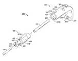
- FIG. 1is a perspective view of a microwave antenna assembly that employs a coolant delivery system in accordance with an embodiment of the present disclosure
- FIG. 2is a cross-sectional view of the antenna assembly depicted in FIG. 1 ;
- FIG. 3Ais an exploded, perspective view of a coolant line clip and a length of tubing including a luer fitting for use with the coolant delivery system depicted in FIG. 1 in accordance with an embodiment of the present disclosure
- FIG. 3Bis a front, perspective view of the coolant line clip connected to the length of tubing depicted in FIG. 3A ;
- FIG. 3Cis a side, perspective view of the coolant line clip connected to the length of tubing depicted in FIG. 3B ;
- FIG. 3Dis a cross-sectional view of the coolant line clip depicted in FIG. 3B ;
- FIG. 3Eis a partial cut-away view of the coolant line clip taken along the line segment “ 3 E- 3 E” in FIG. 3B ;
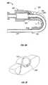
- FIG. 4is a perspective view of the coolant line clip that includes a line lock in accordance with another embodiment of the present disclosure
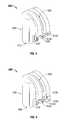
- FIG. 5is a perspective view of the coolant line clip that includes a line lock in accordance with an embodiment of the present disclosure.
- FIG. 6is a flow chart of a method for preventing kinking in tubing in an electrosurgical cooling system in accordance with an embodiment of the present disclosure.
- proximalas is traditional, will refer to the end that is closer to the user, while the term “distal” will refer to the end that is farther from the user.
- the probe assembly 100includes a radiating portion 106 connected by a feedline 114 (or shaft) via a cable 116 that ultimately couples to a generator 30 via connector 118 .
- Probe assembly 100is a dipole microwave antenna assembly, but other suitable antenna assemblies, e.g., monopole or leaky wave antenna assemblies, may also be utilized.
- Radiating portion 106includes a distal end 122 having a tapered end 126 ( FIG. 2 ) that terminates at a tip 110 to facilitate insertion into tissue with minimal resistance. In those cases where the radiating portion 106 is inserted into a pre-existing opening, tip 110 may be rounded or flat.
- Feedline 114includes a coaxial cable made of a conductive metal which may be semi-rigid or flexible. Feedline 114 may also have a variable length from a proximal end of radiating portion 106 to a distal end of cable 116 , depending on particular purpose.
- Probe assembly 100includes a cooling handle assembly 102 having an elongate outer jacket 108 extending therefrom. Outer jacket 108 extends and terminates at tip 110 .
- Microwave antenna 104is positioned within handle assembly 102 such that the radiating portion 106 of antenna 104 extends distally into outer jacket 108 towards tip 110 .
- inflow tubing 124extends into a proximal end of handle body 112 and distally into a portion of outer jacket 108 .
- outflow tubing 126extends from within handle body 112 such that the distal ends of inflow tubing 124 and outflow tubing 126 are in fluid communication with one another.
- In-flow tubing 124 and out-flow tubing 126may be housed together within a casing or jacket (not explicitly shown).
- inflow tubing 124 and outflow tubing 126are positioned within handle body 112 such that coolant (e.g., sterilized water) may be pumped into handle body 112 via a pump 210 ( FIG. 1 ) through inflow tubing 124 .
- coolante.g., sterilized water
- Coolant entering handle body 112comes into direct contact with at least a portion of the shaft of antenna 104 to allow for convective cooling of the antenna shaft to occur.
- the coolantexits handle body 112 via outflow tubing 126 ( FIG. 2 ).
- the coolantis pumped, by way of pump 210 , using any combination of positive and/or negative pressure through inlet tube 124 and outlet tube 126 , respectively.
- the coolantIn pumping the coolant through probe assembly 100 , the coolant typically passes through probe assembly 100 at a uniform flow rate. In another variation, the flow rate may be intermittent such that a volume of coolant may be pumped and allowed to warm up by absorbing heat from the antenna.
- Temperature sensors(not explicitly shown), such as thermistors, thermocouples, etc may be incorporated within or openly associated with the outer jacket 108 to sense the fluid and/or outer jacket 108 temperatures.
- the coolant delivery systemmay be configured to automatically pump additional coolant into antenna assembly 100 once the sensed temperature reaches a predetermined level or it may be configured to notify the user via an audible or visual alarm.
- the coolantis stored in reservoir 212 and has a temperature that varies depending upon desired cooling rates and the desired tissue impedance matching properties.
- Biocompatible coolantshaving sufficient specific heat values for absorbing heat generated by microwave ablation antennas may be utilized, e.g., liquids including, but not limited to, sterile water, saline, Fluorinert, liquid chlorodifluoromethane, and so on.
- gasessuch as nitrous oxide, nitrogen, carbon dioxide, etc. may also be utilized as the coolant.
- probe assembly 100 and coolant delivery system 200For a more detailed description of probe assembly 100 and coolant delivery system 200 , and operative components associated therewith, reference is made to commonly owned U.S. patent application Ser. No. 11/053,987, filed on Feb. 8, 2005, entitled “DEVICES AND METHODS FOR COOLING MICROWAVE ANTENNAS.”
- clip 300is adapted to couple to one or more coolant lines (e.g., inflow tube 124 and/or outflow tube 126 ) of coolant delivery system 200 for use with microwave probe antenna assembly 100 .
- coolant linese.g., inflow tube 124 and/or outflow tube 126
- clip 300is described in terms of use with in-flow tube 124 .
- clip 300is shown and configured to support tubing 124 of coolant system 200 .
- Clip 300includes a clip housing 305 having first and second ends, 302 and 304 , located respectively, at proximal and distal ends thereof. Ends 302 and 304 are configured such that tubing 124 remains in a substantially fixed position along a curve or contour of clip housing 305 during normal operation thereof. Each of the ends 302 , 304 includes respective first openings 302 a and 304 a .
- Clip housing 305also includes a radius “R” ( FIG. 3D ) that allows tubing 124 to flex while coolant flows therethrough.
- a channel 308is defined in clip 300 and extends from first and second openings, 302 a and 304 a , respectively, to provide support for tubing 124 .
- Clip housing 305also includes one or more mechanical interfaces 312 disposed at proximate first and second ends 302 and 304 .
- first opening 302 aincludes an outer periphery 315 defined to mechanically engage a luer fitting 400 (as explained below) and an inner periphery 320 having a suitable diameter for receiving tubing 124 .
- First opening 302 aalso includes a substantially circumferential shape and extends within clip housing 305 toward a distal end thereof. The inner periphery may taper from the first proximal end 302 of clip housing 305 toward the second or distal end 304 to ensure a tight fit between tubing 124 and/or luer fitting 400 and opening 302 a , as best seen in FIG. 3D .
- First opening 302 amay include additional structure that facilitates attachment of the tubing 124 to clip housing 305 , e.g., indents, detents, and the like (not explicitly shown).
- An opening 306 having a suitable diameter and configured to receive tubing 124is defined at a distal end of inner periphery 320 of first opening 302 a , as shown in FIG. 3C and FIG. 3A (in phantom).
- the outer periphery 315includes a mechanical interface configured to engage a corresponding interface disposed on luer fitting 400 .
- the interfacemay be any suitable structure, such as, for example, intents, detents, slits, slots and the like.
- the interfaceincludes two opposing slots 310 a and 310 b each configured to engage corresponding wings 410 a and 410 b of the luer type fitting 400 .
- wings 410 a and 410 bprevent tubing 124 from twisting while tubing 124 is engaged with clip 300 , reducing the risk of impeding coolant flow to and through the probe assembly 100 .
- Other types of mechanical interfacemay be employed to accomplish similar purposes.
- tubing 124is initially inserted into a passageway 405 defined in luer fitting 400 such that the tubing extends therethrough for engagement with clip housing 305 as explained in more detail below.
- Proximal flange 406is configured for slideable reception within luer housing 408 and includes an outer surface 406 ′ having a generally circular shape that is dimensioned to slidingly engage an inner peripheral surface 408 ′ of housing 408 .
- Surface 408 ′may be tapered along a length thereof to facilitate engaging the tube within luer housing 408 .
- Flange 406also includes an inner periphery 407 that defines passageway 405 .
- the tube 124is secured by sliding flange 406 into luer housing 408 such that the tapered inner surface 408 ′ of luer housing 406 crimps and secures the tube 124 in a uniformly concentric manner.
- inner periphery 407may be tapered along a length thereof to facilitate securing the tube 124 within luer fitting 400 .
- the outer surface 406 ′ of flange 406may be tapered such that the tube 124 is crimped and secured upon reception of the flange into luer housing 408 .
- inner peripheral surface 408 ′is not necessarily tapered.
- luer fitting 400includes a housing 408 that includes an integrally-formed proximal flange 406 that extends therefrom.
- the proximal flange 406receives the tube 124 for passage through passageway 405 for engagement with clip housing 305 .
- the tube 124is permitted to rotate within the luer fitting 400 that may be suitable for a particular surgical purpose.
- the surgical instrument(not shown) may need a particularly-designed coupling (not shown) to avoid twisting the tube 124 during use.
- the distal end of the tube 124is fed through opening 302 a in clip housing 305 , around channel 308 , and through exit opening 304 a disposed in end 304 .
- the luer fitting 400is then oriented such that the two opposing wings 410 a and 410 b align with the corresponding slots 310 a and 310 b , respectively, in clip housing 305 and moved into secure engagement therewith.
- the engagement of the wings 410 a and 410 b within respective slots 310 a and 310 bprevents the tube 124 from twisting during use. Because the clip 300 and luer 400 assembly maintains the tubing 124 substantially fixed, movement of the probe 100 and/or the tubing 124 adjacent thereto will not cause the tubing to kink during normal operation thereof.
- channel 308is configured to extend from opening 306 along a length of clip housing 305 to second opening 304 a disposed in distal end 304 .
- the surface 308 ′ of channel 308is configured to provide support for tubing 124 within clip 300 .
- the surface 308 ′ of channel 308has a diameter that is slightly greater than the diameter of tubing 124 such that tubing 124 easily rests therein.
- surface 308 ′may include a diameter that is slightly less than or equal to tubing 124 such that tubing 124 is further secured within clip housing 305 .
- Channel 308may be coated with a material that reduces static and kinetic coefficients of friction between the tubing 124 and the channel surface 308 ′.
- channel surface 308 ′may be coated with nylon, TEFLONTM and the like.
- channel 308is open along a length of clip housing 305 to enable a visual confirmation of coolant flow, or lack thereof, through the tubing 124 .
- Channel 305includes a generally J-shape having a suitable radius “R” that allows tube 124 to flex during operation of coolant delivery system 200 (see FIG. 3D ).
- Radius “R”includes a sufficient diameter that provides adequate structural support for tubing 124 , while providing clip housing 305 and, thus, tubing 124 some degree of flexibility.
- the distal end 304includes an opening 304 a extending therethrough that is dimensioned to mechanically engage the tubing 124 as the tubing extends therethrough.
- an alternative clip 600may be utilized.
- Clip 600includes a clip housing 605 , one or more slots 610 , and a generally J-shaped support channel 608 (similar to the J-channel described above) that extends to a distal end 604 .
- the distal end 604includes a pair of opposing flanges 612 a and 612 b that are flexible to facilitate insertion of the tube 124 therein.
- the two opposing flanges 612 a and 612 bare preferably made from a semi-resilient material to flex inwardly or outwardly to facilitate insertion of the tube in the clip housing 605 .
- the flanges 612 a and 612 bmay be dimensioned to flex inwardly such that the tube 124 may be essentially snap-fit into secure engagement with the distal end 604 .
- the flanges 612 a and 612 bmay be dimensioned to flew outwardly (either together or independently) to facilitate secure engagement with the tube 124 .
- FIG. 5shows another embodiment of a clip 500 that includes a housing 505 , one or more slots 510 , and a generally J-shaped support channel 508 that extends to a distal end 504 .
- the distal end 404includes a pair of opposing flanges 512 a and 512 b that are flexible to facilitate insertion of the tube 124 therein.
- the two opposing flanges 512 a and 512 bare preferably made from a semi-resilient material to flex inwardly or outwardly to facilitate insertion of the tube in the clip housing 505 .
- Flanges 512 a and 512 bare dimensioned to flex outwardly to secure tube 124 into secure engagement with the distal end 504 .
- Flange 512 aincludes a distal end 513 a that includes a mechanical interface, e.g., nub, is biased inwardly to enhance retention of the tube 124 within distal end 504 . More particularly, upon insertion, tube 124 forces flange 512 a outwardly past a distal end 513 b of flange 512 b and, once the tube 124 is seated within channel 508 , the biasing overlapping force of flange 512 a against flange 512 b enhances the retention of both flanges 512 a and 512 b (with the distal ends 513 a and 513 b working in cooperation) against the tube 124 .
- a mechanical interfacee.g., nub
- Clip housing 305 and luer housing 405may be made from any suitable material including but not limited to, metal, metal alloy, plastic, plastic composite, and the like. In embodiments, it may prove useful to fabricate clip housing 305 and luer housing 405 from one or more biocompatible materials such as, for example, silicone elastomer, polyvinyl chloride, natural or synthetic rubber, polyurethane and so on. Clip housing 305 and luer housing 405 may be formed by stamping, overmolding, injection molding, or by other suitable means known in the art.
- clip 300 and luer 400have been described herein as connecting to an end of tubing 124 that is connected to probe assembly 100 , it is within the purview of the present disclosure to have clip 300 and luer 400 adapted to connect to an end of tube 124 that is connected to the coolant system 200 .
- clip 300 and luer 400may operate and include structure similar to that as described hereinabove.
- Clip 300 and/or luer 400may be adapted to connect to one or more other clips 300 and/or luers 400 .
- one or more clips 300 and/or luers 400may include interlocking interfaces configured to couple one or more clips together. This may be useful when tubing 124 is employed in limited working areas.
- Clip housing 305may have more than one channel 308 .
- one clip 300may be employed to couple to multiple coolant lines (e.g., coolant lines that include in-flow and out-flow lines).
- clip housing 305may have a C-shape, U-shape, M-shape, and so on (none of which is explicitly shown) each having respective ends converging toward each other and each having suitable radii at their respective converging locations.
- clip 300 and luer 400While the structural and operative features of clip 300 and luer 400 have been described in terms of use with a single length of tubing, it is within the purview of the present disclosure to provide a clip 300 and luer 400 that may couple to coolant lines and/or cables that are housed within one cover, jacket, or sheath.
- clip 300 and luer 400may be configured similarly as described hereinabove, but may have components including respective openings that are configured to accommodate larger diameter structure.
- clip housing 305may have an additional, or larger diameter, opening 306 at the distal end of inner periphery 320 , wherein two channels (not shown) may extend from opening 306 , as described above with regard to channel 308 , and accommodate both lengths of tubing.
- a second opening (not shown), or other suitable structure, at second end 304may be employed to maintain the lengths of tubing as described above.
- the present disclosureprovides a method 700 of preventing kinking in tubing in a cooling system.
- a clip housinghaving proximal and distal ends and a channel defined therethrough and a luer including a passageway defined therethrough is provided.
- the channel and the passagewayare dimensioned to receive tubing for carrying a cooling fluid from a cooling source.
- the tubingis inserted into and through the passageway in the luer and the luer is secured to the tubing.
- the tubingis inserted into and through the channel of the clip housing such that the tubing extends therefrom for engagement with an instrument.
- mating mechanical interfaces on the luerare operatively engaged with corresponding mechanical interfaces on the clip housing to limit rotation of the tubing.
- the present disclosurealso provides a coolant delivery system for use with a microwave antenna.
- the coolant delivery systemincludes one or more lengths of tubing having one end adapted to connect to a microwave antenna and a second end adapted to connect to a coolant reservoir configured to store at least one type of coolant.
- the coolant delivery systemincludes a clip housing having proximal and distal ends and a channel defined therethrough. The channel configured to receive the one or more lengths tubing for carrying a cooling fluid from the coolant reservoir.
- the coolant delivery systemalso includes a luer that includes a passageway defined therethrough. The passageway is configured to securely receive the one or more lengths of tubing such that the tubing extends through the luer for reception within the channel defined in the clip housing.
- the luerincludes one or more interfaces on a surface thereof that matingly engage a corresponding interface on the clip housing to limit rotation of the tubing.
Landscapes
- Health & Medical Sciences (AREA)
- Engineering & Computer Science (AREA)
- Life Sciences & Earth Sciences (AREA)
- Surgery (AREA)
- Electromagnetism (AREA)
- Animal Behavior & Ethology (AREA)
- Nuclear Medicine, Radiotherapy & Molecular Imaging (AREA)
- Otolaryngology (AREA)
- Veterinary Medicine (AREA)
- General Engineering & Computer Science (AREA)
- Biomedical Technology (AREA)
- Heart & Thoracic Surgery (AREA)
- Medical Informatics (AREA)
- Molecular Biology (AREA)
- Physics & Mathematics (AREA)
- General Health & Medical Sciences (AREA)
- Public Health (AREA)
- Mechanical Engineering (AREA)
- Surgical Instruments (AREA)
Abstract
Description
Claims (20)
Priority Applications (2)
| Application Number | Priority Date | Filing Date | Title |
|---|---|---|---|
| US12/123,645US8037895B2 (en) | 2008-05-20 | 2008-05-20 | Coolant line clip assemblies for use with fluid delivery systems |
| US13/268,054US8424553B2 (en) | 2008-05-20 | 2011-10-07 | Coolant line clip assemblies for use with fluid delivery systems |
Applications Claiming Priority (1)
| Application Number | Priority Date | Filing Date | Title |
|---|---|---|---|
| US12/123,645US8037895B2 (en) | 2008-05-20 | 2008-05-20 | Coolant line clip assemblies for use with fluid delivery systems |
Related Child Applications (1)
| Application Number | Title | Priority Date | Filing Date |
|---|---|---|---|
| US13/268,054ContinuationUS8424553B2 (en) | 2008-05-20 | 2011-10-07 | Coolant line clip assemblies for use with fluid delivery systems |
Publications (2)
| Publication Number | Publication Date |
|---|---|
| US20090289151A1 US20090289151A1 (en) | 2009-11-26 |
| US8037895B2true US8037895B2 (en) | 2011-10-18 |
Family
ID=41341367
Family Applications (2)
| Application Number | Title | Priority Date | Filing Date |
|---|---|---|---|
| US12/123,645Active2030-05-26US8037895B2 (en) | 2008-05-20 | 2008-05-20 | Coolant line clip assemblies for use with fluid delivery systems |
| US13/268,054Expired - Fee RelatedUS8424553B2 (en) | 2008-05-20 | 2011-10-07 | Coolant line clip assemblies for use with fluid delivery systems |
Family Applications After (1)
| Application Number | Title | Priority Date | Filing Date |
|---|---|---|---|
| US13/268,054Expired - Fee RelatedUS8424553B2 (en) | 2008-05-20 | 2011-10-07 | Coolant line clip assemblies for use with fluid delivery systems |
Country Status (1)
| Country | Link |
|---|---|
| US (2) | US8037895B2 (en) |
Cited By (3)
| Publication number | Priority date | Publication date | Assignee | Title |
|---|---|---|---|---|
| US20120029502A1 (en)* | 2008-05-20 | 2012-02-02 | Vivant Medical, Inc. | Coolant Line Clip Assemblies For Use With Fluid Delivery Systems |
| US20140024246A1 (en)* | 2012-07-20 | 2014-01-23 | Airbus Operations Gmbh | Cable support device and electrical connector assembly |
| US20140167591A1 (en)* | 2010-03-26 | 2014-06-19 | Whirlpool Corporation | Method and apparatus for routing utilities in a refrigerator |
Citations (44)
| Publication number | Priority date | Publication date | Assignee | Title |
|---|---|---|---|---|
| US1911229A (en) | 1932-02-12 | 1933-05-30 | Harry F Gleim | Injecting device |
| US3942528A (en) | 1974-07-18 | 1976-03-09 | Loeser Edward A | Non-kinking intravenous tube loop device |
| US4435174A (en) | 1982-04-12 | 1984-03-06 | American Hospital Supply Corporation | Catheter guide |
| USD273993S (en) | 1982-02-05 | 1984-05-22 | Pudenz-Schulte Med, Research Corp. | Catheter clip |
| US4645492A (en) | 1983-10-11 | 1987-02-24 | Medical Engineering Corporation | Catheter anchoring device |
| US4758174A (en) | 1987-01-20 | 1988-07-19 | Molex Incorporated | Environmentally sealed electrical connector |
| US4802864A (en) | 1987-01-20 | 1989-02-07 | Molex Incorporated | Right angle strain relief adapter for electrical connectors |
| US5192273A (en) | 1989-07-24 | 1993-03-09 | Steven F. Bierman | Catheterization system |
| US5314411A (en) | 1989-07-24 | 1994-05-24 | Steven F. Bierman, M.D. | Catheterization system with universal retention device and method of use |
| USD350201S (en) | 1992-10-08 | 1994-08-30 | Abbott Laboratories | External retaining device for a feeding tube |
| US5354282A (en) | 1990-05-04 | 1994-10-11 | Bierman Steven F | Catheter anchoring system |
| US5456671A (en) | 1989-07-24 | 1995-10-10 | Bierman; Steven F. | Catheter anchoring system |
| US5578013A (en) | 1989-07-24 | 1996-11-26 | Venetec International, Inc. | Catheter anchoring system |
| US5620333A (en) | 1994-12-07 | 1997-04-15 | Burndy Corporation | Electrical connector strain relief hood |
| US5640476A (en) | 1995-07-14 | 1997-06-17 | Siecor Corporation | Guide sleeve for fiber optic cable |
| US5672847A (en) | 1995-11-13 | 1997-09-30 | Piatt; John Allen | Computer cable bender |
| US5690616A (en) | 1996-01-16 | 1997-11-25 | Mogg; Alan David | Catheter clamp |
| US5702371A (en) | 1989-07-24 | 1997-12-30 | Venetec International, Inc. | Tube fitting anchoring system |
| US5710851A (en) | 1995-11-06 | 1998-01-20 | Amphenol Corporation | Strain relief system for a fiber optic connector |
| US5860952A (en) | 1996-01-11 | 1999-01-19 | C. R. Bard, Inc. | Corporeal access tube assembly and method |
| US5890926A (en) | 1997-03-26 | 1999-04-06 | The Whitaker Corporation | Cable bend controller |
| US5910128A (en) | 1996-01-11 | 1999-06-08 | C. R. Bard, Inc. | Retention balloon and corporeal access tube assembly |
| US5916199A (en) | 1996-07-11 | 1999-06-29 | Miles; John E. | Tapeless tubing anchoring system with intravenous applications |
| US5957894A (en)* | 1997-01-03 | 1999-09-28 | Sherwood Services Ag | Intravenous connection clip |
| US6001081A (en) | 1997-09-02 | 1999-12-14 | Dionex Corp. | Kink inhibiting device |
| US6013875A (en) | 1998-08-04 | 2000-01-11 | Fridenberg; Stephen J. | Transitional sleeving for coaxial cable |
| US6036673A (en) | 1996-01-11 | 2000-03-14 | C. R. Bard, Inc. | Bolster for corporeal access tube assembly |
| US6159198A (en) | 1998-07-16 | 2000-12-12 | Medtronic, Inc. | Introducer system |
| US6427953B1 (en) | 2001-06-22 | 2002-08-06 | Bellsouth Intellectual Property Corporation | Cable supporting apparatus |
| US6428515B1 (en) | 2000-06-01 | 2002-08-06 | Venetec International, Inc. | Anchoring system for leur lock connector |
| US6554489B2 (en) | 2001-03-28 | 2003-04-29 | Corning Cable Systems Llc | Fiber optic cable guide and method of application |
| US6634801B1 (en) | 2000-11-14 | 2003-10-21 | Stratos Lightwave, Inc. | Adjustable strain relief boot |
| US6695490B2 (en) | 2000-04-21 | 2004-02-24 | Yazaki Corporation | Optical ring network, optical connector, and hybrid connector |
| US6808315B2 (en) | 2001-11-14 | 2004-10-26 | Autonetworks Technologies, Ltd. | Optical connector integrally formed so as to limit the bend radius of an optical fiber cord |
| US6817780B2 (en) | 2003-01-15 | 2004-11-16 | Fci Americas Technology, Inc. | Guide boot for a fiber-optic cable |
| US6878136B2 (en) | 2002-02-28 | 2005-04-12 | Medical Product Specialists | Huber needle with anti-rebound safety mechanism |
| US6918894B2 (en) | 2002-02-28 | 2005-07-19 | Medical Product Specialists | Huber needle with anti-rebound safety mechanism |
| USD525359S1 (en) | 2004-09-02 | 2006-07-18 | Medical Components, Inc. | Precurved catheter clip |
| US7198066B2 (en) | 2001-10-23 | 2007-04-03 | Novarix Ltd., Oxford Centre For Innovation | Device for supporting and stabilising a tubing for fluid transport and such a tubing |
| USD543277S1 (en) | 2005-01-18 | 2007-05-22 | White James E | Y-injection site patient bracelet fob for I.V. administration sets |
| US7229051B2 (en) | 2005-02-14 | 2007-06-12 | Mailhot Jr Robert | Support device for guidewires and catheters and method of use thereof |
| US7312407B2 (en) | 2006-01-28 | 2007-12-25 | Gerald Case | Non-metallic elbow conduit transition fitting |
| US7354421B2 (en) | 2002-10-01 | 2008-04-08 | Venetec International, Inc. | Catheter securement device |
| US7799015B2 (en)* | 2003-10-16 | 2010-09-21 | Medical Components, Inc. | Method for securing a clip to a conduit connection |
Family Cites Families (3)
| Publication number | Priority date | Publication date | Assignee | Title |
|---|---|---|---|---|
| US20060161115A1 (en)* | 2004-11-05 | 2006-07-20 | Fangrow Thomas F | Soft-grip medical connector |
| FR2918284B1 (en)* | 2007-07-02 | 2009-08-28 | Vygon Sa | DEVICE FOR INTRODUCING A CATHETER GUIDE WIRE IN A VESSEL |
| US8037895B2 (en)* | 2008-05-20 | 2011-10-18 | Vivant Medical, Inc. | Coolant line clip assemblies for use with fluid delivery systems |
- 2008
- 2008-05-20USUS12/123,645patent/US8037895B2/enactiveActive
- 2011
- 2011-10-07USUS13/268,054patent/US8424553B2/ennot_activeExpired - Fee Related
Patent Citations (48)
| Publication number | Priority date | Publication date | Assignee | Title |
|---|---|---|---|---|
| US1911229A (en) | 1932-02-12 | 1933-05-30 | Harry F Gleim | Injecting device |
| US3942528A (en) | 1974-07-18 | 1976-03-09 | Loeser Edward A | Non-kinking intravenous tube loop device |
| USD273993S (en) | 1982-02-05 | 1984-05-22 | Pudenz-Schulte Med, Research Corp. | Catheter clip |
| US4435174A (en) | 1982-04-12 | 1984-03-06 | American Hospital Supply Corporation | Catheter guide |
| US4645492A (en) | 1983-10-11 | 1987-02-24 | Medical Engineering Corporation | Catheter anchoring device |
| US4758174A (en) | 1987-01-20 | 1988-07-19 | Molex Incorporated | Environmentally sealed electrical connector |
| US4802864A (en) | 1987-01-20 | 1989-02-07 | Molex Incorporated | Right angle strain relief adapter for electrical connectors |
| US5578013A (en) | 1989-07-24 | 1996-11-26 | Venetec International, Inc. | Catheter anchoring system |
| US5314411A (en) | 1989-07-24 | 1994-05-24 | Steven F. Bierman, M.D. | Catheterization system with universal retention device and method of use |
| US5456671A (en) | 1989-07-24 | 1995-10-10 | Bierman; Steven F. | Catheter anchoring system |
| US5192273A (en) | 1989-07-24 | 1993-03-09 | Steven F. Bierman | Catheterization system |
| US5947931A (en) | 1989-07-24 | 1999-09-07 | Venetec International, Inc. | Tube fitting anchoring system |
| US5702371A (en) | 1989-07-24 | 1997-12-30 | Venetec International, Inc. | Tube fitting anchoring system |
| US5354282A (en) | 1990-05-04 | 1994-10-11 | Bierman Steven F | Catheter anchoring system |
| USD350201S (en) | 1992-10-08 | 1994-08-30 | Abbott Laboratories | External retaining device for a feeding tube |
| US5620333A (en) | 1994-12-07 | 1997-04-15 | Burndy Corporation | Electrical connector strain relief hood |
| US5640476A (en) | 1995-07-14 | 1997-06-17 | Siecor Corporation | Guide sleeve for fiber optic cable |
| US5710851A (en) | 1995-11-06 | 1998-01-20 | Amphenol Corporation | Strain relief system for a fiber optic connector |
| US5672847A (en) | 1995-11-13 | 1997-09-30 | Piatt; John Allen | Computer cable bender |
| US6036673A (en) | 1996-01-11 | 2000-03-14 | C. R. Bard, Inc. | Bolster for corporeal access tube assembly |
| US5860952A (en) | 1996-01-11 | 1999-01-19 | C. R. Bard, Inc. | Corporeal access tube assembly and method |
| US5910128A (en) | 1996-01-11 | 1999-06-08 | C. R. Bard, Inc. | Retention balloon and corporeal access tube assembly |
| US5690616A (en) | 1996-01-16 | 1997-11-25 | Mogg; Alan David | Catheter clamp |
| US5916199A (en) | 1996-07-11 | 1999-06-29 | Miles; John E. | Tapeless tubing anchoring system with intravenous applications |
| US5957894A (en)* | 1997-01-03 | 1999-09-28 | Sherwood Services Ag | Intravenous connection clip |
| US5890926A (en) | 1997-03-26 | 1999-04-06 | The Whitaker Corporation | Cable bend controller |
| US6001081A (en) | 1997-09-02 | 1999-12-14 | Dionex Corp. | Kink inhibiting device |
| US6544247B1 (en) | 1998-07-16 | 2003-04-08 | Medtronic, Inc. | Introducer system |
| US6159198A (en) | 1998-07-16 | 2000-12-12 | Medtronic, Inc. | Introducer system |
| US6013875A (en) | 1998-08-04 | 2000-01-11 | Fridenberg; Stephen J. | Transitional sleeving for coaxial cable |
| US6695490B2 (en) | 2000-04-21 | 2004-02-24 | Yazaki Corporation | Optical ring network, optical connector, and hybrid connector |
| US6428515B1 (en) | 2000-06-01 | 2002-08-06 | Venetec International, Inc. | Anchoring system for leur lock connector |
| US6634801B1 (en) | 2000-11-14 | 2003-10-21 | Stratos Lightwave, Inc. | Adjustable strain relief boot |
| US6554489B2 (en) | 2001-03-28 | 2003-04-29 | Corning Cable Systems Llc | Fiber optic cable guide and method of application |
| US6427953B1 (en) | 2001-06-22 | 2002-08-06 | Bellsouth Intellectual Property Corporation | Cable supporting apparatus |
| US6477770B1 (en) | 2001-06-22 | 2002-11-12 | Bellsouth Intellectual Property Corporation | Cable supporting methods |
| US7198066B2 (en) | 2001-10-23 | 2007-04-03 | Novarix Ltd., Oxford Centre For Innovation | Device for supporting and stabilising a tubing for fluid transport and such a tubing |
| US6808315B2 (en) | 2001-11-14 | 2004-10-26 | Autonetworks Technologies, Ltd. | Optical connector integrally formed so as to limit the bend radius of an optical fiber cord |
| US6878136B2 (en) | 2002-02-28 | 2005-04-12 | Medical Product Specialists | Huber needle with anti-rebound safety mechanism |
| US6918894B2 (en) | 2002-02-28 | 2005-07-19 | Medical Product Specialists | Huber needle with anti-rebound safety mechanism |
| US7354421B2 (en) | 2002-10-01 | 2008-04-08 | Venetec International, Inc. | Catheter securement device |
| US6932515B2 (en) | 2003-01-15 | 2005-08-23 | Fci Americas Technology, Inc. | Guide boot for a fiber-optic cable |
| US6817780B2 (en) | 2003-01-15 | 2004-11-16 | Fci Americas Technology, Inc. | Guide boot for a fiber-optic cable |
| US7799015B2 (en)* | 2003-10-16 | 2010-09-21 | Medical Components, Inc. | Method for securing a clip to a conduit connection |
| USD525359S1 (en) | 2004-09-02 | 2006-07-18 | Medical Components, Inc. | Precurved catheter clip |
| USD543277S1 (en) | 2005-01-18 | 2007-05-22 | White James E | Y-injection site patient bracelet fob for I.V. administration sets |
| US7229051B2 (en) | 2005-02-14 | 2007-06-12 | Mailhot Jr Robert | Support device for guidewires and catheters and method of use thereof |
| US7312407B2 (en) | 2006-01-28 | 2007-12-25 | Gerald Case | Non-metallic elbow conduit transition fitting |
Cited By (5)
| Publication number | Priority date | Publication date | Assignee | Title |
|---|---|---|---|---|
| US20120029502A1 (en)* | 2008-05-20 | 2012-02-02 | Vivant Medical, Inc. | Coolant Line Clip Assemblies For Use With Fluid Delivery Systems |
| US8424553B2 (en)* | 2008-05-20 | 2013-04-23 | Covidien Lp | Coolant line clip assemblies for use with fluid delivery systems |
| US20140167591A1 (en)* | 2010-03-26 | 2014-06-19 | Whirlpool Corporation | Method and apparatus for routing utilities in a refrigerator |
| US9719717B2 (en)* | 2010-03-26 | 2017-08-01 | Whirlpool Corporation | Method and apparatus for routing utilities in a refrigerator |
| US20140024246A1 (en)* | 2012-07-20 | 2014-01-23 | Airbus Operations Gmbh | Cable support device and electrical connector assembly |
Also Published As
| Publication number | Publication date |
|---|---|
| US8424553B2 (en) | 2013-04-23 |
| US20120029502A1 (en) | 2012-02-02 |
| US20090289151A1 (en) | 2009-11-26 |
Similar Documents
| Publication | Publication Date | Title |
|---|---|---|
| EP2295000B1 (en) | Devices for cooling microwave antennas | |
| CN102245258B (en) | Coolant injection tube | |
| AU2009201253B8 (en) | Re-hydration antenna for ablation | |
| AU2006201855B2 (en) | Reinforced high strength microwave antenna | |
| CN101437477B (en) | Heat exchange conduit with multilumen tube with liquid return channel | |
| AU734265B2 (en) | Urethral warming catheter | |
| US8292880B2 (en) | Targeted cooling of deployable microwave antenna | |
| US20150164587A1 (en) | Intracooled percutaneous microwave ablation probe | |
| US8333762B2 (en) | Irrigated catheter with improved irrigation flow | |
| US9057468B2 (en) | Wedge coupling | |
| US8424553B2 (en) | Coolant line clip assemblies for use with fluid delivery systems | |
| US20200188684A1 (en) | Polymer Introducer for Use with an RF Ablation Probe and Associated RF Ablation Probe Assembly | |
| US11957409B2 (en) | Irrigation cooling structure for microwave ablation tissue probe | |
| CN113543691A (en) | Systems and methods for energy delivery | |
| CN110063789B (en) | Microwave ablation device | |
| CN221533857U (en) | Adjustable curved sheath pipe | |
| CN221555732U (en) | Adjustable curved sheath pipe | |
| AU2004260453B2 (en) | Devices and methods for cooling microwave antennas |
Legal Events
| Date | Code | Title | Description |
|---|---|---|---|
| AS | Assignment | Owner name:VIVANT MEDICAL, INC., COLORADO Free format text:ASSIGNMENT OF ASSIGNORS INTEREST;ASSIGNOR:DECARLO, ARNOLD V.;REEL/FRAME:021476/0478 Effective date:20080903 | |
| STCF | Information on status: patent grant | Free format text:PATENTED CASE | |
| AS | Assignment | Owner name:VIVANT LLC, COLORADO Free format text:CHANGE OF NAME;ASSIGNOR:VIVANT MEDICAL, INC.;REEL/FRAME:030138/0053 Effective date:20121226 Owner name:COVIDIEN LP, MASSACHUSETTS Free format text:ASSIGNMENT OF ASSIGNORS INTEREST;ASSIGNOR:VIVANT LLC;REEL/FRAME:030135/0582 Effective date:20130402 | |
| FPAY | Fee payment | Year of fee payment:4 | |
| AS | Assignment | Owner name:VIVANT MEDICAL LLC, COLORADO Free format text:CHANGE OF NAME;ASSIGNOR:VIVANT MEDICAL, INC.;REEL/FRAME:038299/0168 Effective date:20121226 | |
| AS | Assignment | Owner name:COVIDIEN LP, MASSACHUSETTS Free format text:ASSIGNMENT OF ASSIGNORS INTEREST;ASSIGNOR:VIVANT MEDICAL LLC;REEL/FRAME:038343/0394 Effective date:20121228 | |
| MAFP | Maintenance fee payment | Free format text:PAYMENT OF MAINTENANCE FEE, 8TH YEAR, LARGE ENTITY (ORIGINAL EVENT CODE: M1552); ENTITY STATUS OF PATENT OWNER: LARGE ENTITY Year of fee payment:8 | |
| MAFP | Maintenance fee payment | Free format text:PAYMENT OF MAINTENANCE FEE, 12TH YEAR, LARGE ENTITY (ORIGINAL EVENT CODE: M1553); ENTITY STATUS OF PATENT OWNER: LARGE ENTITY Year of fee payment:12 |