US8037348B2 - Vibration-aware data reassignment - Google Patents
Vibration-aware data reassignmentDownload PDFInfo
- Publication number
- US8037348B2 US8037348B2US11/962,270US96227007AUS8037348B2US 8037348 B2US8037348 B2US 8037348B2US 96227007 AUS96227007 AUS 96227007AUS 8037348 B2US8037348 B2US 8037348B2
- Authority
- US
- United States
- Prior art keywords
- data
- storage medium
- vibration
- reassignment
- temporary
- Prior art date
- Legal status (The legal status is an assumption and is not a legal conclusion. Google has not performed a legal analysis and makes no representation as to the accuracy of the status listed.)
- Expired - Fee Related, expires
Links
Images


Classifications
- G—PHYSICS
- G06—COMPUTING OR CALCULATING; COUNTING
- G06F—ELECTRIC DIGITAL DATA PROCESSING
- G06F11/00—Error detection; Error correction; Monitoring
- G06F11/07—Responding to the occurrence of a fault, e.g. fault tolerance
- G06F11/14—Error detection or correction of the data by redundancy in operation
- G06F11/1402—Saving, restoring, recovering or retrying
- G06F11/1415—Saving, restoring, recovering or retrying at system level
- G06F11/1441—Resetting or repowering
- G—PHYSICS
- G11—INFORMATION STORAGE
- G11B—INFORMATION STORAGE BASED ON RELATIVE MOVEMENT BETWEEN RECORD CARRIER AND TRANSDUCER
- G11B19/00—Driving, starting, stopping record carriers not specifically of filamentary or web form, or of supports therefor; Control thereof; Control of operating function ; Driving both disc and head
- G11B19/02—Control of operating function, e.g. switching from recording to reproducing
- G11B19/04—Arrangements for preventing, inhibiting, or warning against double recording on the same blank or against other recording or reproducing malfunctions
- G11B19/041—Detection or prevention of read or write errors
- G11B19/042—Detection or prevention of read or write errors due to external shock or vibration
- G—PHYSICS
- G11—INFORMATION STORAGE
- G11B—INFORMATION STORAGE BASED ON RELATIVE MOVEMENT BETWEEN RECORD CARRIER AND TRANSDUCER
- G11B20/00—Signal processing not specific to the method of recording or reproducing; Circuits therefor
- G11B20/10—Digital recording or reproducing
- G11B20/18—Error detection or correction; Testing, e.g. of drop-outs
- G11B20/1879—Direct read-after-write methods
- G—PHYSICS
- G11—INFORMATION STORAGE
- G11B—INFORMATION STORAGE BASED ON RELATIVE MOVEMENT BETWEEN RECORD CARRIER AND TRANSDUCER
- G11B20/00—Signal processing not specific to the method of recording or reproducing; Circuits therefor
- G11B20/10—Digital recording or reproducing
- G11B20/12—Formatting, e.g. arrangement of data block or words on the record carriers
- G11B2020/1264—Formatting, e.g. arrangement of data block or words on the record carriers wherein the formatting concerns a specific kind of data
- G11B2020/1265—Control data, system data or management information, i.e. data used to access or process user data
- G11B2020/1281—Servo information
- G—PHYSICS
- G11—INFORMATION STORAGE
- G11B—INFORMATION STORAGE BASED ON RELATIVE MOVEMENT BETWEEN RECORD CARRIER AND TRANSDUCER
- G11B20/00—Signal processing not specific to the method of recording or reproducing; Circuits therefor
- G11B20/10—Digital recording or reproducing
- G11B20/14—Digital recording or reproducing using self-clocking codes
- G11B20/1403—Digital recording or reproducing using self-clocking codes characterised by the use of two levels
- G11B2020/1484—Codewords used in servo patterns
- G—PHYSICS
- G11—INFORMATION STORAGE
- G11B—INFORMATION STORAGE BASED ON RELATIVE MOVEMENT BETWEEN RECORD CARRIER AND TRANSDUCER
- G11B2220/00—Record carriers by type
- G11B2220/20—Disc-shaped record carriers
- G11B2220/25—Disc-shaped record carriers characterised in that the disc is based on a specific recording technology
- G11B2220/2508—Magnetic discs
- G11B2220/2516—Hard disks
Definitions
- the present disclosurerelates generally to data storage systems, and more particularly, but not by limitation, to data reassignment in data storage systems.
- a disc driveis an example of a type of non-solid state storage system.
- a disc driveincludes at least one rotating disc or storage medium for storage of digital information in a plurality of circular, concentric data tracks. Further, the data tracks (or similarly groups of locations in a solid state device) can be divided into a plurality of data sectors.
- the storage mediumpasses under a respective bearing slider surface.
- Each slidercarries one or more transducers, which writes information to and reads information from the data surfaces of the disc(s). The slider and transducers are often together referred to as a “head.”
- one or more sectors of the storage mediumcan become defective. For example, it sometimes happens that sectors of a storage medium become defective during the manufacturing process of the storage medium. Further, in some instances sectors can become defective during normal operation. Defects can arise in any of the data sectors at various times during the lifetime of the storage system (grown defects). For a disc drive, grown defects include, for example, invading foreign particles which become embedded onto a surface of the storage medium, or external shocks to the storage system which can cause the transducer to nick or crash onto a surface of the storage medium. Defective data sectors pose either temporary or permanent data retrieval problems. To accommodate media defects such as grown defects, a number of spare sectors can be provided on the storage medium. The spare sectors are used to replace defective sectors on the storage medium.
- a data storage systemis subjected to momentary shock and/or vibration which can cause data errors, for example during a data write and/or read operation.
- data storage systemssuch as disc drives
- disc drivesare recently being used to a greater extent in hand-held consumer electronics, such as digital music players, cell phones and personal data assistants.
- a disc drive in a hand-held devicecan undergo frequent shock events, such as accidental drops.
- some hand-held devicesthemselves are active shock generators.
- a hand-held phone set on a vibration modecauses momentary shock events during vibration. Even a ring tone on a hand-held phone can provide a source of momentary shock if the volume is set high enough.
- An aspect of the present disclosurerelates to performing a data operation in a data storage system.
- a temporary data reassignmentis performed for a portion of data based on a vibration condition of the data storage system.
- One exemplary aspectrelates to a method of performing a data operation.
- the methodincludes implementing a data operation for a portion of data and detecting a data error during the data operation.
- the methodfurther includes obtaining an indication of a vibration condition associated with a device with which the data operation is performed and implementing a temporary reassignment of the portion of data based on the vibration condition.
- a controlleris configured to implement a data write operation of a portion of data to the target storage medium and detect a data error during the write operation.
- the controlleris further configured to receive a signal from the vibration detection component indicative of a vibration condition during the write operation and implement a temporary reassignment of data to the temporary data storage location based on the vibration condition.
- Another exemplary aspectrelates to a method that includes detecting a data error during a data operation and obtaining a vibration status from a vibration detection component. Further, in response to the detected data error, and based on the vibration status, the data operation is either retried or the data operation is reassigned. In response to retrying the data operation, the steps of detecting a data error and obtaining a vibration status are repeated.
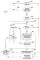
- FIG. 1is a schematic diagram of one embodiment of a data storage system.
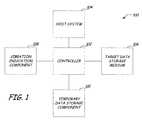
- FIG. 2is an exploded perspective view of one embodiment of a disc drive.
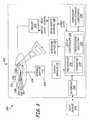
- FIG. 3illustrates a schematic diagram of the disc drive illustrated in FIG. 3 .
- FIG. 4is a flow diagram of a method of performing a data write operation in a data storage system
- FIG. 5is a schematic diagram of one embodiment of a temporary data storage component.
- FIG. 6illustrates a method for creating the temporary data storage component of FIG. 5 .
- FIG. 7illustrates one embodiment of a method for storing data in a temporary data storage component.
- FIG. 8is a schematic diagram illustrating portions of an exemplary target storage medium and a temporary data storage component.
- FIG. 9illustrates one embodiment of a method for performing a temporary data reassignment including a retry loop.
- FIG. 10illustrates one embodiment of a method for writing data stored in a temporary data storage component to a target storage medium.
- FIG. 1is a schematic diagram illustrating one embodiment of a data storage system 100 .
- System 100includes a controller 102 configured to control certain operations of data storage system 100 in a known manner.
- Controller 102is communicatively coupled to a host device or system 104 and is configured to transmit, receive, access, and/or process data within system 100 .
- controller 102can communicate data with one or more devices, components, applications, and/or subsystems of system 100 such as, but not limited to, a transmitter, receiver, data storage device, format conversion device, encoder (compressor), decoder (decompressor), buffer, multiplexor, or modulator.
- controller 102is configured to receive data from host system 104 and provide the data to be stored on target data storage medium 106 . Further, controller 102 is configured to access target data storage medium 106 to retrieve data stored on medium 106 . Controller 102 can provide the retrieved data to host system 104 and/or other components of system 100 . Controller 102 can also be configured, if desired, to perform seek operations to locate desired portions of storage medium 106 . For example, controller 102 can include a servo controller configured to seek a read/write head to a desired track of storage medium 106 .
- Target data storage medium 106can include any type of storage medium configured to store data, including solid-state media and non-solid state media.
- storage medium 106can include a hard disc, floppy and/or removable disc, random access memory (RAM), magnetoresistive random access memory (MRAM), dynamic random access memory (DRAM), electrically erasable programmable read-only memory (EEPROM), a flash memory drive, and/or any other type of storage device.
- RAMrandom access memory
- MRAMmagnetoresistive random access memory
- DRAMdynamic random access memory
- EEPROMelectrically erasable programmable read-only memory
- flash memory driveand/or any other type of storage device.
- storage medium 106includes one or more hard discs, such as magnetic and/or optical discs.
- portions of data storage medium 106can become defective.
- one or more sectors of data storage medium 106can experience grown defects.
- controller 102can be configured to perform data reallocation or reassignment.
- a number of spare sectorscan be provided on target storage medium 106 and can be utilized to replace the defective sectors encountered during operation.
- system 100can include a temporary data storage component 110 configured to store data.
- Controller 102is communicatively coupled to temporary data storage component 110 and is configured to send data to and receive data from component 110 .
- temporary data storage component 110is utilized to store data temporarily within system 100 .
- component 110can be used as a buffer for storing data to be written to target data storage medium 106 .
- controller 102is configured to implement a temporary data reassignment such that data to be written to target data storage medium 106 is temporarily stored in component 110 .
- temporary data storage component 110examples include both solid-state media and non-solid state media.
- temporary data storage component 110can include a hard disc, floppy and/or removable disc, random access memory (RAM), magnetoresistive random access memory (MRAM), electrically erasable programmable read-only memory (EEPROM), a flash memory drive, and/or any other type of storage device.
- RAMrandom access memory
- MRAMmagnetoresistive random access memory
- EEPROMelectrically erasable programmable read-only memory
- flash memory driveand/or any other type of storage device.
- data storage component 110can be separate from target storage medium 106 .
- all or part of component 110can be included within target storage medium 106 .
- system 100is employed in an environment in which data storage medium 106 can frequently be exposed to momentary shock and vibrations due to the portability and/or functionality of the environment in which it is located.
- data storage medium 106can be provided in a consumer electronic device, such as, but not limited to, portable electronic devices, digital music players, mobile phones, personal data assistants, etc.
- a momentary shock or vibrationcan cause a data error during a data write (or read) operation to target storage medium 106 .
- system 100can also include a vibration indication component 108 configured to provide a signal indicative of a vibration condition to controller 102 .
- vibration indication component 108can include a shock detection circuit configured to provide a signal indicative of a vibration amplitude.
- vibration indication component 108can also be configured to provide servo error code associated with a write and/or read operation.
- a position error signalPES
- a position error signal (PES)that is above a threshold amplitude or has some known characteristic can indicate the presence of a vibration during a data operation.
- FIGS. 2 and 3illustrate one particular embodiment of a data storage system 200 having a rotatable data storage medium.
- data storage system 200includes a disc drive.
- one or more embodiments of the present disclosureare also useful in other types of data storage systems.
- data storage system 200includes a housing 202 having a cover 204 and a base 206 .
- cover 204attaches to base 206 to form an enclosure 208 enclosed by a perimeter wall 210 of base 206 .
- the components of data storage system 200are assembled to base 206 and are enclosed in enclosure 208 of housing 202 .
- disc drive 200includes a disc or storage medium 212 .
- FIG. 2illustrates storage medium 212 as a single disc, those skilled in the art should understand that more than one disc can be used in data storage system 200 .
- Storage medium 212stores information in a plurality of circular, concentric data tracks which are further subdivided into data sectors.
- Storage medium 212is mounted on a spindle motor assembly 214 by a disc clamp 216 and pin 218 .
- Spindle motor assembly 214rotates medium 212 causing its data surfaces to pass under respective hydrodynamic bearing slider surfaces.
- Each surface of medium 212has an associated slider 220 , which carries transducers that communicate with the surface of the medium. The slider and transducers are often together referred to as a read/write head.
- sliders 220are supported by suspension assemblies 222 , which are, in turn, attached to track accessing arms 224 of an actuator mechanism 226 .
- Actuator mechanism 226is rotated about a shaft 228 by a voice coil motor 230 , which is controlled by servo control circuitry within internal circuit 232 .
- Voice coil motor 230rotates actuator mechanism 226 to position sliders 220 relative to desired data tracks, between a disc inner diameter 231 and a disc outer diameter 233 .
- FIG. 3is a simplified block diagram of data storage system 200 illustrated in FIG. 2 having housing 202 .
- Data storage system 200includes a controller 236 and processing circuitry 234 used for controlling certain operations of data storage system 200 in a known manner.
- Data storage system 200can include a preamplifier (preamp) 238 for generating a write signal applied to sliders 220 during a write operation, and for amplifying a read signal emanating from slider 220 during a read operation.
- preamppreamplifier
- a read/write channel 240receives data from processing circuitry 234 during a write operation, and provides encoded write data to preamplifier 238 .
- preampprocesses a read signal generated by preamp 238 in order to detect and decode data recorded on medium 212 .
- the decoded datais provided to processing circuitry 234 and ultimately through interface 242 to a host device 244 .
- storage medium 212is logically divided into a plurality of data segments.
- An example data track 236 and example data segments 238 - 241are illustrated in FIG. 3 .
- data segments 238 - 241are considered to be data sectors for storage of user data.
- data segments 238 - 241can also be considered data wedges. Data wedges can span across more than one data sector as well as include partial data sectors.
- Data storage system 200includes servo controller 236 which generates control signals applied to VCM 230 and spindle motor 214 .
- Processing circuitry 234instructs servo controller 236 to move read/write head 220 to desired tracks.
- Servo controller 236is also responsive to servo data, such as servo burst information recorded on medium 212 in embedded servo fields or servo wedges included in the data tracks.
- Both track seeking and track following operationstypically include generation of a position error signal (PES) by PES module 232 which gives an indication of the radial position of the read/write head with respect to the tracks on the disc.
- PESposition error signal
- a write and/or read operation of system 200can be block or suspended.
- controller 236can be configured to implement a retry of a blocked or suspended data operation.
- a vibration detection componentcan include a component configured to check a servo error code associated with a data operation.
- a position error signal (PES) module 232can be configured to generate a PES during a write operation.
- the PESgives an indication of the radial position of a read/write head with respect to particular tracks on storage medium 212 .
- the PEScan be utilized to indicate vibration within data storage system 200 .
- controller 236can be configured to detect when the PES deviation exceeds a threshold value and, in response, control a data operation within system 200 .
- controller 236can cause at least a portion of the write operation to be blocked based on the PES generated by PES module 232 .
- a vibration detection componentcan include a component configured to receive an indication of a vibration condition from host 244 .
- Host 244is communicatively coupled to controller 236 via interface 242 .
- host device 244can be configured to implement a component (not shown in FIG. 3 ) that includes a source of vibration or shock.
- host device 244can be configured to active a component, such as a vibrator, ringer, and/or speaker, that generates a vibration within system 200 .
- Host 244can provide an indication that a source of vibration is about to be activated.
- Controller 236can be configured to control data operations (e.g., data read and/or write operations) based on vibration indications received from host device 244 .
- data segmentscan become defective or “bad” during normal operation of data storage system 200 .
- one or more segments (e.g., sectors 238 - 241 ) on medium 212can be determined to contain a media defect.
- segments of medium 212can experience grown defects which include, for example, invading foreign particles which become embedded onto the surface of the disc, or external shocks to the storage system which can cause the transducer to nick or crash onto the surface of the disc.
- Such media defectspose either temporary or permanent data retrieval problems.
- controller 236 and/or processing circuitry 234can be configured to carry out a reallocation or reassignment of data.
- storage medium 212can include a reserve of spare segments for replacing the defective segments. If a defective segment is discovered, data in the defective segment is reassigned to a spare segment.
- the determination of the defectiveness of a segmentis often determined during a write or read operation. For instance, during a data operation, such as a data write operation, controller 236 can encounter a data error. The controller 236 can implement a data retry in an attempt to correct the encountered data error.
- system 200can be configured to perform a “mini-cert” operation in which a write verify is performed followed by a read operation to determine if the sector contains a media defect. If the system 200 determines that a media defect exists, the system 200 can perform a data reassignment to a spare sector of medium 212 .
- data storage system 200can include a temporary data storage component 270 .
- temporary data storage component 270is substantially similar to component 110 illustrated in FIG. 1 .
- Examples of temporary data storage component 270include both solid-state media and non-solid state media.
- temporary data storage component 270can include a hard disc, floppy and/or removable disc, random access memory (RAM), magnetoresistive random access memory (MRAM), electrically erasable programmable read-only memory (EEPROM), a flash memory drive, and/or any other type of storage device.
- RAMrandom access memory
- MRAMmagnetoresistive random access memory
- EEPROMelectrically erasable programmable read-only memory
- flash memory driveand/or any other type of storage device.
- data storage component 270can be separate from storage medium 212 .
- temporary data storage component 270is illustrated within housing 202 , it is noted that in other embodiments temporary data storage component 270 can be provided outside housing 202 and/or remote from data storage system 200 . Temporary data storage component 270 is configured to provide one or more temporary data storage locations for storing data. For example, temporary data storage component 270 can operate as a cache or buffer memory for temporarily storing data provided by controller 236 .
- data storage system 200 illustrated in FIGS. 2 and 3can be used, for example, in hand-held consumer electronic products, such as digital music players, cell phones, personal data assistants and etc.
- data storage system 200can frequently be exposed to momentary shock and/or vibration events due to the portability of hand-held devices in which it is located.
- vibrations and/or shock eventscan cause data errors during operation of system 200 .
- burst errorsare types of error that data storage system 200 can experience.
- vibrations and/or shockcan cause the read/write head 220 to significantly deviate from a center of a desired track of medium 212 thus causing a data error in a data write operation to the desired track, for instance.
- the vibration and/or shockcan cause system 200 to determine incorrectly that one or more segments of medium 212 contain media defects.
- vibration and/or momentary shockcan cause a data storage system to identify sectors as containing media defects and implement a data reassignment to spare sectors of the storage medium even though the underlying media of the original sector is not defective.
- the data storage system 200may reassign many of the data segments attempted to be written, and therefore consecutively reassign data segments that may not need to be reassigned because the underlying media of the data segments are not defective. This type of behavior is known as consecutive reassignment.
- data storage system 200may attempt to repeatedly rewrite the same data to many different spare sectors. This type of behavior is known as repeated reassignment.
- Repeated reassignment and reassignment of consecutive data segmentscan have many detrimental consequences. For example, repeatable reassignment and consecutive reassignment of data segments can vastly limit an amount of capacity that a data storage system can utilize.
- a data storage systemcan run out of precious spare data segment space.
- a repeated reassignmentconsumes at least one new spare data segment for each repeat.
- a disc drive that runs out of spare data segmentsis unable to handle new grown defects and functions abnormally.
- the host operationscan time out. Each data segment in error can undergo a series of time-consuming defect tests before it is finally considered defective and is reassigned. Consecutive or repeated reassignment can significantly prolong write operations.
- a reassignment list or table associated with the spare sectors of medium 212can grow rapidly and become full with repeated and consecutive reassignments. Consecutive reassignments generate many reassignment entries and although repeated reassignment generates only a single reassignment entry, each reassignment entry due to repeated reassignment occupies more space than a single entry because all previously used replacement segments must be recorded with the reassignment list such that previously used replacement segments will not be used as replacement segments again upon new reassigning.
- a full reassignment listrenders a disc drive unable to handle new grown defects. Further, vibration and/or shock present at medium 212 during a data reassignment to medium 212 can cause a reassignment table failure in which an error occurs while writing data to the reassignment table.
- processing circuitrysuch as processing circuitry 234 ( FIG. 3 ) handles write errors during write operations and limits, or prevents, false media defects, repeated reassignment of data segments, and/or consecutive reassignment of data segments.
- FIG. 4illustrates a flow diagram of a method 400 of performing a data write operation in a data storage system, such as the data storage system illustrated in FIG. 3 . While method 400 is described in the context of a data write operation, it is noted that the concepts described herein can be utilized in the context of other data operations including, but not limited to, data read operations, data processing operations, data transmit and receive operations, and data access operations.
- a data write operationincludes writing data to one or more target locations (such as sectors) of a target storage medium, such as storage medium 212 .
- a data erroris encountered at step 404 .
- a data error during a write operationcan be caused by, for example, a media defect and/or misalignment of the read/write head over the storage medium. For instance, vibration and/or momentary shock can cause the read/write head to deviate from a desired position over a target track.
- the sectors of the target storage medium that are determined to contain data errorsare referred to as error sectors.
- an indication of a vibration condition present during the data write operationis obtained.
- the indicationcan include, for example, an output from shock detection circuit, such as shock sensor 231 and/or checking servo error code associated with the data write operation. For instance, a position error signal (PES) associated with the write operation can be checked.
- PESposition error signal
- the servo error code or PEScan provide evidence that a vibration was present during the data write operation.
- a temporary data reassignmentis implemented based on the vibration condition indication obtained at step 406 .
- the temporary data reassignmentcan be implemented at step 408 if step 406 indicated that a significant vibration was present during the write operation to the error sector at step 402 .
- the temporary data reassignmentincludes storing the data from the write attempt at step 402 to a temporary data storage location at step 410 .
- datacan be stored to a temporary data storage location in a temporary data storage component, such as component 270 illustrated in FIG. 3 .
- temporary data storage component 270can be positioned within the same housing as the target storage medium (i.e., medium 212 ) or can be positioned remote from the target storage medium. In either case, the temporary data storage location can also be exposed to momentary shock and/or vibration during a data write (or read) operation to the temporary data storage location. In one embodiment, the temporary data storage location is configured such that a write (or read) operation of data to the temporary data storage location is less susceptible to data errors caused by vibration than a write operation of data to the target storage medium.
- the temporary data storage locationcan include solid-state memory such as, but not limited to, flash memory.
- the methodcontinues to decision block 412 wherein the method determines if the write operation has completed. For instance, the method returns to step 402 and continues to write data to any remaining sectors of the target storage medium. If block 412 determines that the write operation has completed, the method 400 proceeds to step 414 wherein data stored on the temporary storage component is written back the target storage medium. In one embodiment, data is written from the temporary storage component to the target storage medium after the vibration condition has terminated and/or when the data storage system is idle. The data can be written back to the original error sectors of the target storage medium or can be written to a spare sector of the target storage medium.
- FIG. 5illustrates one embodiment of a temporary data storage component 500 .
- Component 500is one example of a temporary data storage component that can be utilized in system 200 .
- Component 500includes a temporary data store 502 comprising one or more storage locations 503 .
- locations 503can include sectors or segments of a storage medium, including solid-state and/or non-solid state storage media.
- Examples of temporary data storage component 500include a hard disc, floppy and/or removable disc, random access memory (RAM), magnetoresistive random access memory (MRAM), dynamic random access memory (DRAM), electrically erasable programmable read-only memory (EEPROM), a flash memory drive, and/or any other type of storage device.
- RAMrandom access memory
- MRAMmagnetoresistive random access memory
- DRAMdynamic random access memory
- EEPROMelectrically erasable programmable read-only memory
- flash memory driveand/or any other type of storage device.
- Temporary data storage component 500also includes a spare table 504 and a temporary data reassignment table 506 . Although illustrated as residing within component 500 , one or more of spare table 504 and reassignment table 506 can be external to component 500 .
- Spare table 504includes information relating to the available spare locations 503 and/or their physical location within temporary data storage component 500 .
- temporary data reassignment table 506includes entries that map temporary data storage locations 503 to error sector of a target storage medium (i.e. medium 212 ) for which data is stored in component 500 .
- FIG. 6illustrates a method 600 for establishing temporary data storage component 500 .
- temporary spare locations 503are allocated within temporary data storage component 500 .
- temporary spare table 504is created in temporary data storage component 500 .
- the temporary reassignment table 506is created.
- FIG. 7illustrates one embodiment of a method 700 for storing data in temporary data storage component 500 .
- method 700is implemented by controller 236 illustrated in FIG. 3 . Further, in one example method 700 is utilized for storing data at step 410 illustrated in FIG. 4 .
- Method 700begins at step 702 wherein a portion of data is identified to be written to temporary storage component 500 . For example, a portion of data from an error sector of a target storage medium, for example medium 212 , is identified.
- temporary data storage component 500is searched to determine an availability of one or more storage locations 503 .
- spare table 504is accessed to determine the physical locations of the storage locations 503 in component 500 .
- step 704can determine whether a sufficient number of segments or sectors in store 502 are available to store the portion of data identified at step 702 . If a number of store locations 503 necessary to store the portion of data are determined to be available, the method stores the data to one or more storage locations 503 at step 706 .
- an entryis created in the temporary reassignment table 506 that maps the one or more storage locations 503 to corresponding error sectors of the target storage medium.
- the entries in spare table 504 and/or temporary reassignment table 506can be later utilized in retrieving stored data from component 500 .
- FIG. 8is a schematic diagram illustrating a portion of an exemplary target storage medium 802 , such as storage medium 212 .
- Target data storage medium 802includes one or more sectors 803 to which data is written during a data operation.
- FIG. 8also illustrates a plurality of temporary data storage locations (i.e., spares) 804 of a temporary data storage component (i.e. component 500 ).
- datais written to sectors 803 in a sequential manner wherein data is first written to sectors 0 and 1 of medium 802 .
- sectors 806i.e., sector 2
- a temporary data reassignmentis implemented wherein the data from the write attempt to sector 806 is temporarily stored in a portion 810 of temporary data storage locations 804 .
- an entryis created in a temporary reassignment table (i.e. table 506 ). The entry includes data that maps portion 810 to error sector 806 .
- the data write operationscontinues such that data is written to sectors 3 and 4 of medium 802 .
- a data erroris encountered.
- a temporary data reassignmentis implemented wherein the data from the write attempt to sector 808 is stored in a portion 812 of temporary data storage locations 804 .
- an entryis created in the temporary reassignment table. The entry includes data that maps portion 812 to error sector 808 .
- FIG. 9illustrates one embodiment of a method 900 for performing a temporary data reassignment including a retry loop 921 .
- Method 900will be described below in the context of data storage system 200 , illustrated in FIG. 2 . However, the concepts described below can be implemented in other data storage system types and configurations.
- Method 900begins at block 902 and a write command is performed at step 904 .
- the write commandcan include writing data to one or more target sectors of a target storage medium (i.e., medium 212 ).
- method 900ends at block 908 . If the write command is not completed, the method continues to decision block 910 wherein a portion of data is written to a sector of the target storage medium. Block 910 determines whether a write error was encountered during the write operation. If a write error was not encountered, the method 900 returns to block 904 wherein the write command continues for any remaining sectors.
- step 910determines that a write error was encountered during the write operation
- the methodcontinues to decision block 912 wherein the write error is verified. For example, a write retry operation can be performed. If the error has cleared, the method returns to block 904 . If the write error has not cleared, the method continues to block 914 wherein a vibration condition status is obtained from one or more vibration detection components.
- the vibration condition statuscan indicate whether a significant vibration was present at the storage system during the write operation.
- step 914can include receiving a signal from a shock detection circuit, such as shock sensor 231 .
- the shock detection circuitprovides a signal indicative of an amplitude of an observed vibration, for example.
- step 914can include checking a servo error code. As discussed above, a position error signal (PES) associated with the write operation can be checked to determine if the PES exceeded a threshold value during the write operation.
- PESposition error signal
- step 916the method determines whether a vibration was detected at block 914 . If a vibration was not detected, the method continues to block 918 wherein a conventional sector reassignment is implemented. For example, in one embodiment step 918 includes replacing the defective sector with a spare sector provided on target data storage medium 212 .
- retry loop 921determines at decision block 920 whether the vibration condition has exceeded a pre-determined threshold duration. If a threshold duration has not been exceeded, retry loop 921 returns to block 912 wherein the method 900 determines whether the error has cleared. It is noted that retry loop 921 can also include an optional decision block 923 that determines if an amplitude of the vibration has fallen to a acceptable level before performing a write retry/verify at step 912 . In one embodiment, step 923 is substantially similar to steps 914 and 916 .
- a data write retry and/or verifycan be implemented to determine if the write command can be successfully completed. If the error has not cleared at block 912 , loop 921 continues to blocks 914 and 916 to determine a vibration condition status. As illustrated, loop 921 generally indicates a delayed reassignment loop that repeatedly retries the write operation and detects vibration.
- Step 922determines whether a spare data storage location is available on a temporary data storage component, such as component 500 illustrated in FIG. 5 . For example, decision block 922 determines whether a spare location is available in the temporary data storage component. If a temporary data storage location is not available, the method 900 continues to step 918 wherein the error sector is reassigned to a spare sector associated with the target storage medium (i.e., medium 212 ). In this manner, the data from the error sector is stored to a spare sector on the target storage medium.
- the target storage mediumi.e., medium 212
- step 922the method 900 implements a temporary data reassignment that includes storing the data from the error sector to a temporary storage location at step 924 .
- step 924implements method 700 illustrated in FIG. 7 .
- step 918After the data is written to a spare sector on target storage medium (step 918 ) or to a temporary storage location (step 924 ), the method 900 proceeds to step 904 wherein the write command is continued for any remaining sectors.
- FIG. 10illustrates a method 1000 for writing data stored in the temporary data storage component 500 back to the target storage medium (i.e. medium 212 ).
- the methodbegins at block 1001 .
- the method 1000determines whether the data storage system is stable and/or idle. For example, step 1002 determines whether the data storage system is currently performing a data write or read operation, and/or whether a vibration is present at the storage system. If the system is not sufficiently idle and/or stable, the method ends at block 1003 . If the system is determined to be stable, the method 1000 proceeds to decision block 1004 wherein the temporary reassignment table is checked to determine if the table contains at least one entry mapping data stored in the temporary storage component. If the temporary reassignment table is empty, the method 1000 proceeds to block 1003 wherein the method terminates.
- step 1006the method 1000 proceeds to step 1006 wherein one or more of the temporary reassignment entries in the reassignment table are retrieved.
- entries in the reassignment tablecan contain information mapping data stored in the temporary storage locations to original error sectors on the target storage medium.
- the original error sectors on the target storage mediumare checked to determine whether the error sectors contain a media defect.
- step 1008can include a write and/or read verify.
- the methodproceeds to block 1012 wherein the error sector is reassigned to a spare sector on the target storage medium. If the error sector passes the test at step 1010 , data is written from the temporary storage component to the original sector on the disk. Following a successful write of data at steps 1012 or 1014 , the temporary reassignment entry is deleted from the temporary reassignment table at step 1016 and the method returns to block 1002 .
Landscapes
- Engineering & Computer Science (AREA)
- Signal Processing (AREA)
- Theoretical Computer Science (AREA)
- Quality & Reliability (AREA)
- Physics & Mathematics (AREA)
- General Engineering & Computer Science (AREA)
- General Physics & Mathematics (AREA)
- Signal Processing For Digital Recording And Reproducing (AREA)
Abstract
Description
Claims (19)
Priority Applications (1)
| Application Number | Priority Date | Filing Date | Title |
|---|---|---|---|
| US11/962,270US8037348B2 (en) | 2007-12-21 | 2007-12-21 | Vibration-aware data reassignment |
Applications Claiming Priority (1)
| Application Number | Priority Date | Filing Date | Title |
|---|---|---|---|
| US11/962,270US8037348B2 (en) | 2007-12-21 | 2007-12-21 | Vibration-aware data reassignment |
Publications (2)
| Publication Number | Publication Date |
|---|---|
| US20090164843A1 US20090164843A1 (en) | 2009-06-25 |
| US8037348B2true US8037348B2 (en) | 2011-10-11 |
Family
ID=40790111
Family Applications (1)
| Application Number | Title | Priority Date | Filing Date |
|---|---|---|---|
| US11/962,270Expired - Fee RelatedUS8037348B2 (en) | 2007-12-21 | 2007-12-21 | Vibration-aware data reassignment |
Country Status (1)
| Country | Link |
|---|---|
| US (1) | US8037348B2 (en) |
Cited By (9)
| Publication number | Priority date | Publication date | Assignee | Title |
|---|---|---|---|---|
| US20110125976A1 (en)* | 2004-10-12 | 2011-05-26 | Vanman Robert V | Method of and system for mobile surveillance and event recording |
| US20150331637A1 (en)* | 2014-05-16 | 2015-11-19 | Western Digital Technologies, Inc. | Vibration mitigation for a data storage device |
| US9257143B1 (en)* | 2014-12-23 | 2016-02-09 | Western Digital Technologies, Inc. | Precautionary measures for data storage device environmental conditions |
| US9298380B1 (en)* | 2014-01-22 | 2016-03-29 | Western Digital Technologies, Inc. | Data storage device with selective write to a first storage media or a second storage media |
| CN105590642A (en)* | 2014-11-06 | 2016-05-18 | 西部数据技术公司 | Mechanical Shock Mitigation For Data Storage |
| US9594628B2 (en) | 2014-07-30 | 2017-03-14 | Segate Technology Llc | Operational vibration compensation through media cache management |
| US9860536B2 (en) | 2008-02-15 | 2018-01-02 | Enforcement Video, Llc | System and method for high-resolution storage of images |
| US10341605B1 (en) | 2016-04-07 | 2019-07-02 | WatchGuard, Inc. | Systems and methods for multiple-resolution storage of media streams |
| US11264056B1 (en)* | 2020-10-01 | 2022-03-01 | Seagate Technology Llc | System and method for write-retry management |
Families Citing this family (5)
| Publication number | Priority date | Publication date | Assignee | Title |
|---|---|---|---|---|
| US9606858B2 (en)* | 2010-04-26 | 2017-03-28 | International Business Machines Corporation | Temporarily storing an encoded data slice |
| GB2506164A (en) | 2012-09-24 | 2014-03-26 | Ibm | Increased database performance via migration of data to faster storage |
| US9304930B2 (en)* | 2014-03-21 | 2016-04-05 | Seagate Technology Llc | HDD write buffer zone for vibration condition |
| US10593362B2 (en)* | 2017-08-14 | 2020-03-17 | Seagate Technology Llc | Interlaced magnetic recording storage system |
| US11462245B1 (en) | 2021-08-25 | 2022-10-04 | Seagate Technology Llc | Vibration-induced on-cylinder limit adjustment |
Citations (36)
| Publication number | Priority date | Publication date | Assignee | Title |
|---|---|---|---|---|
| US5130969A (en) | 1989-02-15 | 1992-07-14 | Sony Corporation | Apparatus having defective sector compensation coupled with analog information mode and digital information mode recording/reproducing capability |
| US5493676A (en)* | 1993-06-29 | 1996-02-20 | Unisys Corporation | Severe environment data recording system |
| US5710943A (en)* | 1995-06-30 | 1998-01-20 | Maxtor Corporation | Time based data retention in a variable data rate disk drive |
| US5857059A (en)* | 1991-10-31 | 1999-01-05 | Canon Kabushiki Kaisha | Information recording apparatus |
| US5872905A (en) | 1996-03-14 | 1999-02-16 | Matsushita Electric Industrial Co., Ltd. | Recording area management method, error recovery processing method, and storage apparatus |
| US5918001A (en) | 1996-02-16 | 1999-06-29 | International Business Machines Corporation | Disk drive apparatus and error recovery method in the disk drive |
| US6034831A (en) | 1997-05-09 | 2000-03-07 | International Business Machines Corporation | Dynamic reverse reassign apparatus and method for a data recording disk drive |
| US6078452A (en) | 1998-06-22 | 2000-06-20 | Western Digital Corporation | Disk drive employing method of writing a data block to a data sector following a defective servo sector |
| US6098185A (en) | 1997-10-31 | 2000-08-01 | Stmicroelectronics, N.V. | Header-formatted defective sector management system |
| US6223303B1 (en) | 1998-06-29 | 2001-04-24 | Western Digital Corporation | Disk drive having two tiered defect list comprising marginal and reserved data sectors |
| US6282670B1 (en) | 1997-07-02 | 2001-08-28 | International Business Machines Corporation | Managing defective media in a RAID system |
| US6442715B1 (en)* | 1998-11-05 | 2002-08-27 | Stmicroelectrics N.V. | Look-ahead reallocation disk drive defect management |
| US6490691B1 (en) | 1998-11-26 | 2002-12-03 | International Business Machines Corporation | Error recovery in a disk drive |
| US20030028841A1 (en) | 2001-07-31 | 2003-02-06 | Rushton Nigel Kevin | Data transfer device and method |
| US6530034B1 (en) | 1998-11-09 | 2003-03-04 | International Business Machines Corporation | Method and apparatus for error recovery in a storage device |
| US6545833B1 (en) | 1999-05-07 | 2003-04-08 | Seagate Technology Llc | Method to eliminate reassignments |
| US6557141B1 (en) | 1999-12-01 | 2003-04-29 | Storage Technology Corporation | Magnetic media certification |
| US6574699B1 (en) | 1999-12-07 | 2003-06-03 | International Business Machines Corporation | Fast track reassign in a rotating storage media |
| US6654193B1 (en) | 2001-04-30 | 2003-11-25 | Western Digital Technologies, Inc. | Disk drive for relocating a block of data sectors near a defective servo sector to expedite write operations |
| US6711628B1 (en) | 2002-02-22 | 2004-03-23 | Western Digital Technologies, Inc. | Disk drive aborting a write command before a last target sector reached if an abnormal condition detected and selecting a second command according to a rotational positioning optimization algorithm |
| US6728060B1 (en) | 1999-10-28 | 2004-04-27 | Seagate Technology Llc | Disc drive with delayed reassignment write |
| US6898036B2 (en) | 2001-12-31 | 2005-05-24 | Storage Technology Corporation | System and method for recovery from writing errors during data storage |
| US20050213446A1 (en)* | 2004-02-24 | 2005-09-29 | Norio Tanaka | Optical disk device and method of control of an optical disk |
| US6995943B1 (en)* | 2001-12-11 | 2006-02-07 | Maxtor Corporation | Off-track error recovery method and apparatus for disk drive |
| US7047438B2 (en) | 2002-11-21 | 2006-05-16 | Hitachi Global Storage Technologies Netherlands B.V. | Accommodation of media defect growth on a data storage medium through dynamic remapping |
| US7051154B1 (en) | 1999-07-23 | 2006-05-23 | Seagate Technology, Llc | Caching data from a pool reassigned disk sectors |
| US20060171057A1 (en) | 2005-02-02 | 2006-08-03 | Samsung Electronics Co., Ltd. | Method, medium, and apparatus for processing defects of an HDD |
| US20060215307A1 (en)* | 2005-03-25 | 2006-09-28 | Fujitsu Limited | Storage apparatus, control method and program |
| US20070070542A1 (en) | 2005-09-26 | 2007-03-29 | Fujitsu Limited | Disk control apparatus, disk control method, and computer product |
| US7304816B2 (en)* | 2002-09-16 | 2007-12-04 | Seagate Technology Llc | Disc drive failure prediction |
| US20080189578A1 (en)* | 2007-02-05 | 2008-08-07 | Microsoft Corporation | Disk failure prevention and error correction |
| US7468857B2 (en)* | 2006-02-10 | 2008-12-23 | Maxtor Corporation | Acceleration feed-forward correction enabled or disabled based on track follow loop signals |
| US7490263B2 (en) | 2006-01-17 | 2009-02-10 | Allen King | Apparatus, system, and method for a storage device's enforcing write recovery of erroneous data |
| US7627778B2 (en)* | 2006-12-21 | 2009-12-01 | Seagate Technology Llc | Prediction-based data reassignment |
| US7656599B2 (en)* | 2006-08-29 | 2010-02-02 | Toshiba Storage Device Corporation | Control apparatus, storage apparatus, and computer product |
| US7697226B2 (en)* | 2006-08-29 | 2010-04-13 | Toshiba Storage Device Corporation | Control apparatus, storage apparatus, and computer product |
- 2007
- 2007-12-21USUS11/962,270patent/US8037348B2/ennot_activeExpired - Fee Related
Patent Citations (36)
| Publication number | Priority date | Publication date | Assignee | Title |
|---|---|---|---|---|
| US5130969A (en) | 1989-02-15 | 1992-07-14 | Sony Corporation | Apparatus having defective sector compensation coupled with analog information mode and digital information mode recording/reproducing capability |
| US5857059A (en)* | 1991-10-31 | 1999-01-05 | Canon Kabushiki Kaisha | Information recording apparatus |
| US5493676A (en)* | 1993-06-29 | 1996-02-20 | Unisys Corporation | Severe environment data recording system |
| US5710943A (en)* | 1995-06-30 | 1998-01-20 | Maxtor Corporation | Time based data retention in a variable data rate disk drive |
| US5918001A (en) | 1996-02-16 | 1999-06-29 | International Business Machines Corporation | Disk drive apparatus and error recovery method in the disk drive |
| US5872905A (en) | 1996-03-14 | 1999-02-16 | Matsushita Electric Industrial Co., Ltd. | Recording area management method, error recovery processing method, and storage apparatus |
| US6034831A (en) | 1997-05-09 | 2000-03-07 | International Business Machines Corporation | Dynamic reverse reassign apparatus and method for a data recording disk drive |
| US6282670B1 (en) | 1997-07-02 | 2001-08-28 | International Business Machines Corporation | Managing defective media in a RAID system |
| US6098185A (en) | 1997-10-31 | 2000-08-01 | Stmicroelectronics, N.V. | Header-formatted defective sector management system |
| US6078452A (en) | 1998-06-22 | 2000-06-20 | Western Digital Corporation | Disk drive employing method of writing a data block to a data sector following a defective servo sector |
| US6223303B1 (en) | 1998-06-29 | 2001-04-24 | Western Digital Corporation | Disk drive having two tiered defect list comprising marginal and reserved data sectors |
| US6442715B1 (en)* | 1998-11-05 | 2002-08-27 | Stmicroelectrics N.V. | Look-ahead reallocation disk drive defect management |
| US6530034B1 (en) | 1998-11-09 | 2003-03-04 | International Business Machines Corporation | Method and apparatus for error recovery in a storage device |
| US6490691B1 (en) | 1998-11-26 | 2002-12-03 | International Business Machines Corporation | Error recovery in a disk drive |
| US6545833B1 (en) | 1999-05-07 | 2003-04-08 | Seagate Technology Llc | Method to eliminate reassignments |
| US7051154B1 (en) | 1999-07-23 | 2006-05-23 | Seagate Technology, Llc | Caching data from a pool reassigned disk sectors |
| US6728060B1 (en) | 1999-10-28 | 2004-04-27 | Seagate Technology Llc | Disc drive with delayed reassignment write |
| US6557141B1 (en) | 1999-12-01 | 2003-04-29 | Storage Technology Corporation | Magnetic media certification |
| US6574699B1 (en) | 1999-12-07 | 2003-06-03 | International Business Machines Corporation | Fast track reassign in a rotating storage media |
| US6654193B1 (en) | 2001-04-30 | 2003-11-25 | Western Digital Technologies, Inc. | Disk drive for relocating a block of data sectors near a defective servo sector to expedite write operations |
| US20030028841A1 (en) | 2001-07-31 | 2003-02-06 | Rushton Nigel Kevin | Data transfer device and method |
| US6995943B1 (en)* | 2001-12-11 | 2006-02-07 | Maxtor Corporation | Off-track error recovery method and apparatus for disk drive |
| US6898036B2 (en) | 2001-12-31 | 2005-05-24 | Storage Technology Corporation | System and method for recovery from writing errors during data storage |
| US6711628B1 (en) | 2002-02-22 | 2004-03-23 | Western Digital Technologies, Inc. | Disk drive aborting a write command before a last target sector reached if an abnormal condition detected and selecting a second command according to a rotational positioning optimization algorithm |
| US7304816B2 (en)* | 2002-09-16 | 2007-12-04 | Seagate Technology Llc | Disc drive failure prediction |
| US7047438B2 (en) | 2002-11-21 | 2006-05-16 | Hitachi Global Storage Technologies Netherlands B.V. | Accommodation of media defect growth on a data storage medium through dynamic remapping |
| US20050213446A1 (en)* | 2004-02-24 | 2005-09-29 | Norio Tanaka | Optical disk device and method of control of an optical disk |
| US20060171057A1 (en) | 2005-02-02 | 2006-08-03 | Samsung Electronics Co., Ltd. | Method, medium, and apparatus for processing defects of an HDD |
| US20060215307A1 (en)* | 2005-03-25 | 2006-09-28 | Fujitsu Limited | Storage apparatus, control method and program |
| US20070070542A1 (en) | 2005-09-26 | 2007-03-29 | Fujitsu Limited | Disk control apparatus, disk control method, and computer product |
| US7490263B2 (en) | 2006-01-17 | 2009-02-10 | Allen King | Apparatus, system, and method for a storage device's enforcing write recovery of erroneous data |
| US7468857B2 (en)* | 2006-02-10 | 2008-12-23 | Maxtor Corporation | Acceleration feed-forward correction enabled or disabled based on track follow loop signals |
| US7656599B2 (en)* | 2006-08-29 | 2010-02-02 | Toshiba Storage Device Corporation | Control apparatus, storage apparatus, and computer product |
| US7697226B2 (en)* | 2006-08-29 | 2010-04-13 | Toshiba Storage Device Corporation | Control apparatus, storage apparatus, and computer product |
| US7627778B2 (en)* | 2006-12-21 | 2009-12-01 | Seagate Technology Llc | Prediction-based data reassignment |
| US20080189578A1 (en)* | 2007-02-05 | 2008-08-07 | Microsoft Corporation | Disk failure prevention and error correction |
Non-Patent Citations (1)
| Title |
|---|
| U.S. Appl. No. 11/614,780, Prediction-Based Data Reassignment, filed Dec. 21, 2006. |
Cited By (18)
| Publication number | Priority date | Publication date | Assignee | Title |
|---|---|---|---|---|
| US10075669B2 (en) | 2004-10-12 | 2018-09-11 | WatchGuard, Inc. | Method of and system for mobile surveillance and event recording |
| US20110125976A1 (en)* | 2004-10-12 | 2011-05-26 | Vanman Robert V | Method of and system for mobile surveillance and event recording |
| US9756279B2 (en)* | 2004-10-12 | 2017-09-05 | Enforcement Video, Llc | Method of and system for mobile surveillance and event recording |
| US9871993B2 (en) | 2004-10-12 | 2018-01-16 | WatchGuard, Inc. | Method of and system for mobile surveillance and event recording |
| US10063805B2 (en) | 2004-10-12 | 2018-08-28 | WatchGuard, Inc. | Method of and system for mobile surveillance and event recording |
| US10334249B2 (en) | 2008-02-15 | 2019-06-25 | WatchGuard, Inc. | System and method for high-resolution storage of images |
| US9860536B2 (en) | 2008-02-15 | 2018-01-02 | Enforcement Video, Llc | System and method for high-resolution storage of images |
| US9298380B1 (en)* | 2014-01-22 | 2016-03-29 | Western Digital Technologies, Inc. | Data storage device with selective write to a first storage media or a second storage media |
| US20150331637A1 (en)* | 2014-05-16 | 2015-11-19 | Western Digital Technologies, Inc. | Vibration mitigation for a data storage device |
| US9472222B2 (en)* | 2014-05-16 | 2016-10-18 | Western Digital Technologies, Inc. | Vibration mitigation for a data storage device |
| US9594628B2 (en) | 2014-07-30 | 2017-03-14 | Segate Technology Llc | Operational vibration compensation through media cache management |
| CN105590642A (en)* | 2014-11-06 | 2016-05-18 | 西部数据技术公司 | Mechanical Shock Mitigation For Data Storage |
| CN105590642B (en)* | 2014-11-06 | 2019-04-12 | 西部数据技术公司 | The device and method of mechanical vibration damping for data storage |
| US9257143B1 (en)* | 2014-12-23 | 2016-02-09 | Western Digital Technologies, Inc. | Precautionary measures for data storage device environmental conditions |
| US10341605B1 (en) | 2016-04-07 | 2019-07-02 | WatchGuard, Inc. | Systems and methods for multiple-resolution storage of media streams |
| US11264056B1 (en)* | 2020-10-01 | 2022-03-01 | Seagate Technology Llc | System and method for write-retry management |
| US20220223177A1 (en)* | 2020-10-01 | 2022-07-14 | Seagate Technology Llc | System and method for write-retry management |
| US11682429B2 (en)* | 2020-10-01 | 2023-06-20 | Seagate Technology Llc | System and method for write-retry management |
Also Published As
| Publication number | Publication date |
|---|---|
| US20090164843A1 (en) | 2009-06-25 |
Similar Documents
| Publication | Publication Date | Title |
|---|---|---|
| US8037348B2 (en) | Vibration-aware data reassignment | |
| US8565053B1 (en) | Methods and devices for preventing media errors due to media scratches | |
| US7274639B1 (en) | Disk drive performing multi-level prioritization of entries in a suspect sector list to identify and relocate defective data sectors | |
| CN100570713C (en) | Magnetic recording device, magnetic recording method, and magnetic recording program | |
| US7293226B2 (en) | Method and apparatus for adaptively performing defect scan according to channel characteristics | |
| US8131920B2 (en) | Method and system for dynamically allocating read and write sequence randomizer | |
| US7032127B1 (en) | Method and apparatus for identifying defective areas on a disk surface of a disk drive based on defect density | |
| KR100238156B1 (en) | Detecting method of defect in magnetic storage device | |
| US10867633B1 (en) | Reduced adjacent track erasure from write retry | |
| US7206990B2 (en) | Data sector error handling mechanism | |
| JP3865723B2 (en) | Method for recording data in hard disk drive and control device therefor | |
| US20050188238A1 (en) | Background media scan for recovery of data errors | |
| US20040268033A1 (en) | Refreshing data in a data storage device | |
| US7715140B2 (en) | Method of determining size of error and write control method for hard disc drive, hard disc drive using the write control method, and media storing computer programs for executing the methods | |
| US20060171057A1 (en) | Method, medium, and apparatus for processing defects of an HDD | |
| US7627778B2 (en) | Prediction-based data reassignment | |
| JP3645049B2 (en) | Servo address device and positioning method for read, write and seek operations in a direct access storage device | |
| US8069384B2 (en) | Scanning reassigned data storage locations | |
| US7746586B2 (en) | Media drive, processing method for recording data onto a medium, processing method for data read from a medium, and method for controlling a process for reading data from a medium | |
| US6993688B2 (en) | Data sector error tracking and correction mechanism | |
| US6760170B2 (en) | Servo test method | |
| US7487388B2 (en) | Method of recovering reallocation sectors in data storage system and disc drive using the same | |
| US7817364B2 (en) | Defect reallocation for data tracks having large sector size | |
| US6941488B2 (en) | Retrieval of a single complete copy from multiple stored copies of information | |
| US6263462B1 (en) | Testing method and tester |
Legal Events
| Date | Code | Title | Description |
|---|---|---|---|
| AS | Assignment | Owner name:SEAGATE TECHNOLOGY LLC,CALIFORNIA Free format text:ASSIGNMENT OF ASSIGNORS INTEREST;ASSIGNORS:CHEN, HUAYUAN;WEI, BO;CHEOK, STEVEN TIANCHYE;AND OTHERS;SIGNING DATES FROM 20071219 TO 20071221;REEL/FRAME:020311/0411 Owner name:SEAGATE TECHNOLOGY LLC, CALIFORNIA Free format text:ASSIGNMENT OF ASSIGNORS INTEREST;ASSIGNORS:CHEN, HUAYUAN;WEI, BO;CHEOK, STEVEN TIANCHYE;AND OTHERS;SIGNING DATES FROM 20071219 TO 20071221;REEL/FRAME:020311/0411 | |
| AS | Assignment | Owner name:WELLS FARGO BANK, NATIONAL ASSOCIATION, AS COLLATERAL AGENT AND SECOND PRIORITY REPRESENTATIVE, CALIFORNIA Free format text:SECURITY AGREEMENT;ASSIGNORS:MAXTOR CORPORATION;SEAGATE TECHNOLOGY LLC;SEAGATE TECHNOLOGY INTERNATIONAL;REEL/FRAME:022757/0017 Effective date:20090507 Owner name:JPMORGAN CHASE BANK, N.A., AS ADMINISTRATIVE AGENT AND FIRST PRIORITY REPRESENTATIVE, NEW YORK Free format text:SECURITY AGREEMENT;ASSIGNORS:MAXTOR CORPORATION;SEAGATE TECHNOLOGY LLC;SEAGATE TECHNOLOGY INTERNATIONAL;REEL/FRAME:022757/0017 Effective date:20090507 Owner name:JPMORGAN CHASE BANK, N.A., AS ADMINISTRATIVE AGENT Free format text:SECURITY AGREEMENT;ASSIGNORS:MAXTOR CORPORATION;SEAGATE TECHNOLOGY LLC;SEAGATE TECHNOLOGY INTERNATIONAL;REEL/FRAME:022757/0017 Effective date:20090507 Owner name:WELLS FARGO BANK, NATIONAL ASSOCIATION, AS COLLATE Free format text:SECURITY AGREEMENT;ASSIGNORS:MAXTOR CORPORATION;SEAGATE TECHNOLOGY LLC;SEAGATE TECHNOLOGY INTERNATIONAL;REEL/FRAME:022757/0017 Effective date:20090507 | |
| AS | Assignment | Owner name:SEAGATE TECHNOLOGY INTERNATIONAL, CALIFORNIA Free format text:RELEASE;ASSIGNOR:JPMORGAN CHASE BANK, N.A., AS ADMINISTRATIVE AGENT;REEL/FRAME:025662/0001 Effective date:20110114 Owner name:SEAGATE TECHNOLOGY HDD HOLDINGS, CALIFORNIA Free format text:RELEASE;ASSIGNOR:JPMORGAN CHASE BANK, N.A., AS ADMINISTRATIVE AGENT;REEL/FRAME:025662/0001 Effective date:20110114 Owner name:SEAGATE TECHNOLOGY LLC, CALIFORNIA Free format text:RELEASE;ASSIGNOR:JPMORGAN CHASE BANK, N.A., AS ADMINISTRATIVE AGENT;REEL/FRAME:025662/0001 Effective date:20110114 Owner name:MAXTOR CORPORATION, CALIFORNIA Free format text:RELEASE;ASSIGNOR:JPMORGAN CHASE BANK, N.A., AS ADMINISTRATIVE AGENT;REEL/FRAME:025662/0001 Effective date:20110114 | |
| AS | Assignment | Owner name:THE BANK OF NOVA SCOTIA, AS ADMINISTRATIVE AGENT, CANADA Free format text:SECURITY AGREEMENT;ASSIGNOR:SEAGATE TECHNOLOGY LLC;REEL/FRAME:026010/0350 Effective date:20110118 Owner name:THE BANK OF NOVA SCOTIA, AS ADMINISTRATIVE AGENT, Free format text:SECURITY AGREEMENT;ASSIGNOR:SEAGATE TECHNOLOGY LLC;REEL/FRAME:026010/0350 Effective date:20110118 | |
| ZAAA | Notice of allowance and fees due | Free format text:ORIGINAL CODE: NOA | |
| ZAAB | Notice of allowance mailed | Free format text:ORIGINAL CODE: MN/=. | |
| STCF | Information on status: patent grant | Free format text:PATENTED CASE | |
| FEPP | Fee payment procedure | Free format text:PAYOR NUMBER ASSIGNED (ORIGINAL EVENT CODE: ASPN); ENTITY STATUS OF PATENT OWNER: LARGE ENTITY | |
| AS | Assignment | Owner name:THE BANK OF NOVA SCOTIA, AS ADMINISTRATIVE AGENT, CANADA Free format text:SECURITY AGREEMENT;ASSIGNORS:SEAGATE TECHNOLOGY LLC;EVAULT, INC. (F/K/A I365 INC.);SEAGATE TECHNOLOGY US HOLDINGS, INC.;REEL/FRAME:029127/0527 Effective date:20120718 Owner name:WELLS FARGO BANK, NATIONAL ASSOCIATION, AS COLLATERAL AGENT, CALIFORNIA Free format text:SECOND LIEN PATENT SECURITY AGREEMENT;ASSIGNORS:SEAGATE TECHNOLOGY LLC;EVAULT, INC. (F/K/A I365 INC.);SEAGATE TECHNOLOGY US HOLDINGS, INC.;REEL/FRAME:029253/0585 Effective date:20120718 Owner name:THE BANK OF NOVA SCOTIA, AS ADMINISTRATIVE AGENT, Free format text:SECURITY AGREEMENT;ASSIGNORS:SEAGATE TECHNOLOGY LLC;EVAULT, INC. (F/K/A I365 INC.);SEAGATE TECHNOLOGY US HOLDINGS, INC.;REEL/FRAME:029127/0527 Effective date:20120718 Owner name:WELLS FARGO BANK, NATIONAL ASSOCIATION, AS COLLATE Free format text:SECOND LIEN PATENT SECURITY AGREEMENT;ASSIGNORS:SEAGATE TECHNOLOGY LLC;EVAULT, INC. (F/K/A I365 INC.);SEAGATE TECHNOLOGY US HOLDINGS, INC.;REEL/FRAME:029253/0585 Effective date:20120718 | |
| AS | Assignment | Owner name:EVAULT INC. (F/K/A I365 INC.), CALIFORNIA Free format text:TERMINATION AND RELEASE OF SECURITY INTEREST IN PATENT RIGHTS;ASSIGNOR:WELLS FARGO BANK, NATIONAL ASSOCIATION, AS COLLATERAL AGENT AND SECOND PRIORITY REPRESENTATIVE;REEL/FRAME:030833/0001 Effective date:20130312 Owner name:SEAGATE TECHNOLOGY LLC, CALIFORNIA Free format text:TERMINATION AND RELEASE OF SECURITY INTEREST IN PATENT RIGHTS;ASSIGNOR:WELLS FARGO BANK, NATIONAL ASSOCIATION, AS COLLATERAL AGENT AND SECOND PRIORITY REPRESENTATIVE;REEL/FRAME:030833/0001 Effective date:20130312 Owner name:SEAGATE TECHNOLOGY INTERNATIONAL, CAYMAN ISLANDS Free format text:TERMINATION AND RELEASE OF SECURITY INTEREST IN PATENT RIGHTS;ASSIGNOR:WELLS FARGO BANK, NATIONAL ASSOCIATION, AS COLLATERAL AGENT AND SECOND PRIORITY REPRESENTATIVE;REEL/FRAME:030833/0001 Effective date:20130312 Owner name:SEAGATE TECHNOLOGY US HOLDINGS, INC., CALIFORNIA Free format text:TERMINATION AND RELEASE OF SECURITY INTEREST IN PATENT RIGHTS;ASSIGNOR:WELLS FARGO BANK, NATIONAL ASSOCIATION, AS COLLATERAL AGENT AND SECOND PRIORITY REPRESENTATIVE;REEL/FRAME:030833/0001 Effective date:20130312 | |
| FPAY | Fee payment | Year of fee payment:4 | |
| FEPP | Fee payment procedure | Free format text:7.5 YR SURCHARGE - LATE PMT W/IN 6 MO, LARGE ENTITY (ORIGINAL EVENT CODE: M1555); ENTITY STATUS OF PATENT OWNER: LARGE ENTITY | |
| MAFP | Maintenance fee payment | Free format text:PAYMENT OF MAINTENANCE FEE, 8TH YEAR, LARGE ENTITY (ORIGINAL EVENT CODE: M1552); ENTITY STATUS OF PATENT OWNER: LARGE ENTITY Year of fee payment:8 | |
| FEPP | Fee payment procedure | Free format text:MAINTENANCE FEE REMINDER MAILED (ORIGINAL EVENT CODE: REM.); ENTITY STATUS OF PATENT OWNER: LARGE ENTITY | |
| LAPS | Lapse for failure to pay maintenance fees | Free format text:PATENT EXPIRED FOR FAILURE TO PAY MAINTENANCE FEES (ORIGINAL EVENT CODE: EXP.); ENTITY STATUS OF PATENT OWNER: LARGE ENTITY | |
| STCH | Information on status: patent discontinuation | Free format text:PATENT EXPIRED DUE TO NONPAYMENT OF MAINTENANCE FEES UNDER 37 CFR 1.362 | |
| FP | Lapsed due to failure to pay maintenance fee | Effective date:20231011 | |
| AS | Assignment | Owner name:SEAGATE TECHNOLOGY US HOLDINGS, INC., CALIFORNIA Free format text:RELEASE BY SECURED PARTY;ASSIGNOR:WELLS FARGO BANK, NATIONAL ASSOCIATION, AS COLLATERAL AGENT;REEL/FRAME:067471/0955 Effective date:20240516 Owner name:EVAULT, INC. (F/K/A I365 INC.), CALIFORNIA Free format text:RELEASE BY SECURED PARTY;ASSIGNOR:WELLS FARGO BANK, NATIONAL ASSOCIATION, AS COLLATERAL AGENT;REEL/FRAME:067471/0955 Effective date:20240516 Owner name:SEAGATE TECHNOLOGY LLC, CALIFORNIA Free format text:RELEASE BY SECURED PARTY;ASSIGNOR:WELLS FARGO BANK, NATIONAL ASSOCIATION, AS COLLATERAL AGENT;REEL/FRAME:067471/0955 Effective date:20240516 | |
| AS | Assignment | Owner name:EVAULT INC, CALIFORNIA Free format text:RELEASE BY SECURED PARTY;ASSIGNOR:WELLS FARGO BANK, NATIONAL ASSOCIATION, AS COLLATERAL AGENT;REEL/FRAME:068457/0076 Effective date:20240723 Owner name:SEAGATE TECHNOLOGY LLC, CALIFORNIA Free format text:RELEASE BY SECURED PARTY;ASSIGNOR:WELLS FARGO BANK, NATIONAL ASSOCIATION, AS COLLATERAL AGENT;REEL/FRAME:068457/0076 Effective date:20240723 | |
| AS | Assignment | Owner name:SEAGATE TECHNOLOGY LLC, CALIFORNIA Free format text:RELEASE BY SECURED PARTY;ASSIGNOR:THE BANK OF NOVA SCOTIA;REEL/FRAME:070363/0903 Effective date:20241223 Owner name:EVAULT, INC. (F/K/A I365 INC.), CALIFORNIA Free format text:RELEASE BY SECURED PARTY;ASSIGNOR:THE BANK OF NOVA SCOTIA;REEL/FRAME:070363/0903 Effective date:20241223 Owner name:SEAGATE TECHNOLOGY US HOLDINGS, INC., CALIFORNIA Free format text:RELEASE BY SECURED PARTY;ASSIGNOR:THE BANK OF NOVA SCOTIA;REEL/FRAME:070363/0903 Effective date:20241223 | |
| AS | Assignment | Owner name:SEAGATE TECHNOLOGY PUBLIC LIMITED COMPANY, CALIFORNIA Free format text:RELEASE BY SECURED PARTY;ASSIGNOR:THE BANK OF NOVA SCOTIA;REEL/FRAME:072193/0001 Effective date:20250303 Owner name:SEAGATE TECHNOLOGY, CALIFORNIA Free format text:RELEASE BY SECURED PARTY;ASSIGNOR:THE BANK OF NOVA SCOTIA;REEL/FRAME:072193/0001 Effective date:20250303 Owner name:SEAGATE TECHNOLOGY HDD HOLDINGS, CALIFORNIA Free format text:RELEASE BY SECURED PARTY;ASSIGNOR:THE BANK OF NOVA SCOTIA;REEL/FRAME:072193/0001 Effective date:20250303 Owner name:I365 INC., CALIFORNIA Free format text:RELEASE BY SECURED PARTY;ASSIGNOR:THE BANK OF NOVA SCOTIA;REEL/FRAME:072193/0001 Effective date:20250303 Owner name:SEAGATE TECHNOLOGY LLC, CALIFORNIA Free format text:RELEASE BY SECURED PARTY;ASSIGNOR:THE BANK OF NOVA SCOTIA;REEL/FRAME:072193/0001 Effective date:20250303 Owner name:SEAGATE TECHNOLOGY INTERNATIONAL, CAYMAN ISLANDS Free format text:RELEASE BY SECURED PARTY;ASSIGNOR:THE BANK OF NOVA SCOTIA;REEL/FRAME:072193/0001 Effective date:20250303 Owner name:SEAGATE HDD CAYMAN, CAYMAN ISLANDS Free format text:RELEASE BY SECURED PARTY;ASSIGNOR:THE BANK OF NOVA SCOTIA;REEL/FRAME:072193/0001 Effective date:20250303 Owner name:SEAGATE TECHNOLOGY (US) HOLDINGS, INC., CALIFORNIA Free format text:RELEASE BY SECURED PARTY;ASSIGNOR:THE BANK OF NOVA SCOTIA;REEL/FRAME:072193/0001 Effective date:20250303 |