US8034110B2 - Spinal fusion implant - Google Patents
Spinal fusion implantDownload PDFInfo
- Publication number
- US8034110B2 US8034110B2US11/496,564US49656406AUS8034110B2US 8034110 B2US8034110 B2US 8034110B2US 49656406 AUS49656406 AUS 49656406AUS 8034110 B2US8034110 B2US 8034110B2
- Authority
- US
- United States
- Prior art keywords
- implant
- cage
- insertion guide
- space
- patient
- Prior art date
- Legal status (The legal status is an assumption and is not a legal conclusion. Google has not performed a legal analysis and makes no representation as to the accuracy of the status listed.)
- Active, expires
Links
- 239000007943implantSubstances0.000titleclaimsabstractdescription133
- 230000004927fusionEffects0.000titleclaimsabstractdescription10
- 238000003780insertionMethods0.000claimsabstractdescription83
- 230000037431insertionEffects0.000claimsabstractdescription83
- 238000000034methodMethods0.000claimsabstractdescription47
- 210000003734kidneyAnatomy0.000claimsdescription3
- 238000001356surgical procedureMethods0.000abstractdescription8
- 238000002324minimally invasive surgeryMethods0.000description14
- 230000008901benefitEffects0.000description6
- 239000000463materialSubstances0.000description6
- 210000000988bone and boneAnatomy0.000description5
- 238000001746injection mouldingMethods0.000description4
- 238000013459approachMethods0.000description3
- 230000008468bone growthEffects0.000description3
- 239000002131composite materialSubstances0.000description2
- 238000010586diagramMethods0.000description2
- 238000002513implantationMethods0.000description2
- 229910052751metalInorganic materials0.000description2
- 239000002184metalSubstances0.000description2
- 210000005036nerveAnatomy0.000description2
- 230000001537neural effectEffects0.000description2
- 230000001131transforming effectEffects0.000description2
- 208000008035Back PainDiseases0.000description1
- 229920000049Carbon (fiber)Polymers0.000description1
- 241001269524DuraSpecies0.000description1
- 241000283073Equus caballusSpecies0.000description1
- RTAQQCXQSZGOHL-UHFFFAOYSA-NTitaniumChemical compound[Ti]RTAQQCXQSZGOHL-UHFFFAOYSA-N0.000description1
- 239000000853adhesiveSubstances0.000description1
- 230000001070adhesive effectEffects0.000description1
- 230000002146bilateral effectEffects0.000description1
- 239000000560biocompatible materialSubstances0.000description1
- 230000015572biosynthetic processEffects0.000description1
- 239000004917carbon fiberSubstances0.000description1
- 238000010276constructionMethods0.000description1
- 150000002739metalsChemical class0.000description1
- VNWKTOKETHGBQD-UHFFFAOYSA-NmethaneChemical compoundCVNWKTOKETHGBQD-UHFFFAOYSA-N0.000description1
- HLXZNVUGXRDIFK-UHFFFAOYSA-Nnickel titaniumChemical compound[Ti].[Ti].[Ti].[Ti].[Ti].[Ti].[Ti].[Ti].[Ti].[Ti].[Ti].[Ni].[Ni].[Ni].[Ni].[Ni].[Ni].[Ni].[Ni].[Ni].[Ni].[Ni].[Ni].[Ni].[Ni]HLXZNVUGXRDIFK-UHFFFAOYSA-N0.000description1
- 229910001000nickel titaniumInorganic materials0.000description1
- 229920000642polymerPolymers0.000description1
- 239000007787solidSubstances0.000description1
- 229910001220stainless steelInorganic materials0.000description1
- 239000010935stainless steelSubstances0.000description1
- 239000000126substanceSubstances0.000description1
- 210000000538tailAnatomy0.000description1
- 239000010936titaniumSubstances0.000description1
- 229910052719titaniumInorganic materials0.000description1
Images


Classifications
- A—HUMAN NECESSITIES
- A61—MEDICAL OR VETERINARY SCIENCE; HYGIENE
- A61F—FILTERS IMPLANTABLE INTO BLOOD VESSELS; PROSTHESES; DEVICES PROVIDING PATENCY TO, OR PREVENTING COLLAPSING OF, TUBULAR STRUCTURES OF THE BODY, e.g. STENTS; ORTHOPAEDIC, NURSING OR CONTRACEPTIVE DEVICES; FOMENTATION; TREATMENT OR PROTECTION OF EYES OR EARS; BANDAGES, DRESSINGS OR ABSORBENT PADS; FIRST-AID KITS
- A61F2/00—Filters implantable into blood vessels; Prostheses, i.e. artificial substitutes or replacements for parts of the body; Appliances for connecting them with the body; Devices providing patency to, or preventing collapsing of, tubular structures of the body, e.g. stents
- A61F2/02—Prostheses implantable into the body
- A61F2/30—Joints
- A61F2/44—Joints for the spine, e.g. vertebrae, spinal discs
- A61F2/4455—Joints for the spine, e.g. vertebrae, spinal discs for the fusion of spinal bodies, e.g. intervertebral fusion of adjacent spinal bodies, e.g. fusion cages
- A—HUMAN NECESSITIES
- A61—MEDICAL OR VETERINARY SCIENCE; HYGIENE
- A61F—FILTERS IMPLANTABLE INTO BLOOD VESSELS; PROSTHESES; DEVICES PROVIDING PATENCY TO, OR PREVENTING COLLAPSING OF, TUBULAR STRUCTURES OF THE BODY, e.g. STENTS; ORTHOPAEDIC, NURSING OR CONTRACEPTIVE DEVICES; FOMENTATION; TREATMENT OR PROTECTION OF EYES OR EARS; BANDAGES, DRESSINGS OR ABSORBENT PADS; FIRST-AID KITS
- A61F2/00—Filters implantable into blood vessels; Prostheses, i.e. artificial substitutes or replacements for parts of the body; Appliances for connecting them with the body; Devices providing patency to, or preventing collapsing of, tubular structures of the body, e.g. stents
- A61F2/02—Prostheses implantable into the body
- A61F2/30—Joints
- A61F2/44—Joints for the spine, e.g. vertebrae, spinal discs
- A61F2/442—Intervertebral or spinal discs, e.g. resilient
- A61F2/4425—Intervertebral or spinal discs, e.g. resilient made of articulated components
- A—HUMAN NECESSITIES
- A61—MEDICAL OR VETERINARY SCIENCE; HYGIENE
- A61F—FILTERS IMPLANTABLE INTO BLOOD VESSELS; PROSTHESES; DEVICES PROVIDING PATENCY TO, OR PREVENTING COLLAPSING OF, TUBULAR STRUCTURES OF THE BODY, e.g. STENTS; ORTHOPAEDIC, NURSING OR CONTRACEPTIVE DEVICES; FOMENTATION; TREATMENT OR PROTECTION OF EYES OR EARS; BANDAGES, DRESSINGS OR ABSORBENT PADS; FIRST-AID KITS
- A61F2/00—Filters implantable into blood vessels; Prostheses, i.e. artificial substitutes or replacements for parts of the body; Appliances for connecting them with the body; Devices providing patency to, or preventing collapsing of, tubular structures of the body, e.g. stents
- A61F2/02—Prostheses implantable into the body
- A61F2/30—Joints
- A61F2/44—Joints for the spine, e.g. vertebrae, spinal discs
- A61F2/4455—Joints for the spine, e.g. vertebrae, spinal discs for the fusion of spinal bodies, e.g. intervertebral fusion of adjacent spinal bodies, e.g. fusion cages
- A61F2/4465—Joints for the spine, e.g. vertebrae, spinal discs for the fusion of spinal bodies, e.g. intervertebral fusion of adjacent spinal bodies, e.g. fusion cages having a circular or kidney shaped cross-section substantially perpendicular to the axis of the spine
- A—HUMAN NECESSITIES
- A61—MEDICAL OR VETERINARY SCIENCE; HYGIENE
- A61F—FILTERS IMPLANTABLE INTO BLOOD VESSELS; PROSTHESES; DEVICES PROVIDING PATENCY TO, OR PREVENTING COLLAPSING OF, TUBULAR STRUCTURES OF THE BODY, e.g. STENTS; ORTHOPAEDIC, NURSING OR CONTRACEPTIVE DEVICES; FOMENTATION; TREATMENT OR PROTECTION OF EYES OR EARS; BANDAGES, DRESSINGS OR ABSORBENT PADS; FIRST-AID KITS
- A61F2/00—Filters implantable into blood vessels; Prostheses, i.e. artificial substitutes or replacements for parts of the body; Appliances for connecting them with the body; Devices providing patency to, or preventing collapsing of, tubular structures of the body, e.g. stents
- A61F2/02—Prostheses implantable into the body
- A61F2/30—Joints
- A61F2/44—Joints for the spine, e.g. vertebrae, spinal discs
- A61F2/4455—Joints for the spine, e.g. vertebrae, spinal discs for the fusion of spinal bodies, e.g. intervertebral fusion of adjacent spinal bodies, e.g. fusion cages
- A61F2/447—Joints for the spine, e.g. vertebrae, spinal discs for the fusion of spinal bodies, e.g. intervertebral fusion of adjacent spinal bodies, e.g. fusion cages substantially parallelepipedal, e.g. having a rectangular or trapezoidal cross-section
- A—HUMAN NECESSITIES
- A61—MEDICAL OR VETERINARY SCIENCE; HYGIENE
- A61F—FILTERS IMPLANTABLE INTO BLOOD VESSELS; PROSTHESES; DEVICES PROVIDING PATENCY TO, OR PREVENTING COLLAPSING OF, TUBULAR STRUCTURES OF THE BODY, e.g. STENTS; ORTHOPAEDIC, NURSING OR CONTRACEPTIVE DEVICES; FOMENTATION; TREATMENT OR PROTECTION OF EYES OR EARS; BANDAGES, DRESSINGS OR ABSORBENT PADS; FIRST-AID KITS
- A61F2/00—Filters implantable into blood vessels; Prostheses, i.e. artificial substitutes or replacements for parts of the body; Appliances for connecting them with the body; Devices providing patency to, or preventing collapsing of, tubular structures of the body, e.g. stents
- A61F2/02—Prostheses implantable into the body
- A61F2/30—Joints
- A61F2/46—Special tools for implanting artificial joints
- A61F2/4603—Special tools for implanting artificial joints for insertion or extraction of endoprosthetic joints or of accessories thereof
- A61F2/4611—Special tools for implanting artificial joints for insertion or extraction of endoprosthetic joints or of accessories thereof of spinal prostheses
- A—HUMAN NECESSITIES
- A61—MEDICAL OR VETERINARY SCIENCE; HYGIENE
- A61F—FILTERS IMPLANTABLE INTO BLOOD VESSELS; PROSTHESES; DEVICES PROVIDING PATENCY TO, OR PREVENTING COLLAPSING OF, TUBULAR STRUCTURES OF THE BODY, e.g. STENTS; ORTHOPAEDIC, NURSING OR CONTRACEPTIVE DEVICES; FOMENTATION; TREATMENT OR PROTECTION OF EYES OR EARS; BANDAGES, DRESSINGS OR ABSORBENT PADS; FIRST-AID KITS
- A61F2/00—Filters implantable into blood vessels; Prostheses, i.e. artificial substitutes or replacements for parts of the body; Appliances for connecting them with the body; Devices providing patency to, or preventing collapsing of, tubular structures of the body, e.g. stents
- A61F2/02—Prostheses implantable into the body
- A61F2/28—Bones
- A61F2002/2835—Bone graft implants for filling a bony defect or an endoprosthesis cavity, e.g. by synthetic material or biological material
- A—HUMAN NECESSITIES
- A61—MEDICAL OR VETERINARY SCIENCE; HYGIENE
- A61F—FILTERS IMPLANTABLE INTO BLOOD VESSELS; PROSTHESES; DEVICES PROVIDING PATENCY TO, OR PREVENTING COLLAPSING OF, TUBULAR STRUCTURES OF THE BODY, e.g. STENTS; ORTHOPAEDIC, NURSING OR CONTRACEPTIVE DEVICES; FOMENTATION; TREATMENT OR PROTECTION OF EYES OR EARS; BANDAGES, DRESSINGS OR ABSORBENT PADS; FIRST-AID KITS
- A61F2/00—Filters implantable into blood vessels; Prostheses, i.e. artificial substitutes or replacements for parts of the body; Appliances for connecting them with the body; Devices providing patency to, or preventing collapsing of, tubular structures of the body, e.g. stents
- A61F2/02—Prostheses implantable into the body
- A61F2/30—Joints
- A61F2002/30001—Additional features of subject-matter classified in A61F2/28, A61F2/30 and subgroups thereof
- A61F2002/30108—Shapes
- A61F2002/3011—Cross-sections or two-dimensional shapes
- A61F2002/30112—Rounded shapes, e.g. with rounded corners
- A61F2002/30133—Rounded shapes, e.g. with rounded corners kidney-shaped or bean-shaped
- A—HUMAN NECESSITIES
- A61—MEDICAL OR VETERINARY SCIENCE; HYGIENE
- A61F—FILTERS IMPLANTABLE INTO BLOOD VESSELS; PROSTHESES; DEVICES PROVIDING PATENCY TO, OR PREVENTING COLLAPSING OF, TUBULAR STRUCTURES OF THE BODY, e.g. STENTS; ORTHOPAEDIC, NURSING OR CONTRACEPTIVE DEVICES; FOMENTATION; TREATMENT OR PROTECTION OF EYES OR EARS; BANDAGES, DRESSINGS OR ABSORBENT PADS; FIRST-AID KITS
- A61F2/00—Filters implantable into blood vessels; Prostheses, i.e. artificial substitutes or replacements for parts of the body; Appliances for connecting them with the body; Devices providing patency to, or preventing collapsing of, tubular structures of the body, e.g. stents
- A61F2/02—Prostheses implantable into the body
- A61F2/30—Joints
- A61F2002/30001—Additional features of subject-matter classified in A61F2/28, A61F2/30 and subgroups thereof
- A61F2002/30316—The prosthesis having different structural features at different locations within the same prosthesis; Connections between prosthetic parts; Special structural features of bone or joint prostheses not otherwise provided for
- A61F2002/30329—Connections or couplings between prosthetic parts, e.g. between modular parts; Connecting elements
- A61F2002/30383—Connections or couplings between prosthetic parts, e.g. between modular parts; Connecting elements made by laterally inserting a protrusion, e.g. a rib into a complementarily-shaped groove
- A—HUMAN NECESSITIES
- A61—MEDICAL OR VETERINARY SCIENCE; HYGIENE
- A61F—FILTERS IMPLANTABLE INTO BLOOD VESSELS; PROSTHESES; DEVICES PROVIDING PATENCY TO, OR PREVENTING COLLAPSING OF, TUBULAR STRUCTURES OF THE BODY, e.g. STENTS; ORTHOPAEDIC, NURSING OR CONTRACEPTIVE DEVICES; FOMENTATION; TREATMENT OR PROTECTION OF EYES OR EARS; BANDAGES, DRESSINGS OR ABSORBENT PADS; FIRST-AID KITS
- A61F2/00—Filters implantable into blood vessels; Prostheses, i.e. artificial substitutes or replacements for parts of the body; Appliances for connecting them with the body; Devices providing patency to, or preventing collapsing of, tubular structures of the body, e.g. stents
- A61F2/02—Prostheses implantable into the body
- A61F2/30—Joints
- A61F2002/30001—Additional features of subject-matter classified in A61F2/28, A61F2/30 and subgroups thereof
- A61F2002/30316—The prosthesis having different structural features at different locations within the same prosthesis; Connections between prosthetic parts; Special structural features of bone or joint prostheses not otherwise provided for
- A61F2002/30329—Connections or couplings between prosthetic parts, e.g. between modular parts; Connecting elements
- A61F2002/30471—Connections or couplings between prosthetic parts, e.g. between modular parts; Connecting elements connected by a hinged linkage mechanism, e.g. of the single-bar or multi-bar linkage type
- A—HUMAN NECESSITIES
- A61—MEDICAL OR VETERINARY SCIENCE; HYGIENE
- A61F—FILTERS IMPLANTABLE INTO BLOOD VESSELS; PROSTHESES; DEVICES PROVIDING PATENCY TO, OR PREVENTING COLLAPSING OF, TUBULAR STRUCTURES OF THE BODY, e.g. STENTS; ORTHOPAEDIC, NURSING OR CONTRACEPTIVE DEVICES; FOMENTATION; TREATMENT OR PROTECTION OF EYES OR EARS; BANDAGES, DRESSINGS OR ABSORBENT PADS; FIRST-AID KITS
- A61F2/00—Filters implantable into blood vessels; Prostheses, i.e. artificial substitutes or replacements for parts of the body; Appliances for connecting them with the body; Devices providing patency to, or preventing collapsing of, tubular structures of the body, e.g. stents
- A61F2/02—Prostheses implantable into the body
- A61F2/30—Joints
- A61F2002/30001—Additional features of subject-matter classified in A61F2/28, A61F2/30 and subgroups thereof
- A61F2002/30316—The prosthesis having different structural features at different locations within the same prosthesis; Connections between prosthetic parts; Special structural features of bone or joint prostheses not otherwise provided for
- A61F2002/30535—Special structural features of bone or joint prostheses not otherwise provided for
- A61F2002/30537—Special structural features of bone or joint prostheses not otherwise provided for adjustable
- A61F2002/30538—Special structural features of bone or joint prostheses not otherwise provided for adjustable for adjusting angular orientation
- A—HUMAN NECESSITIES
- A61—MEDICAL OR VETERINARY SCIENCE; HYGIENE
- A61F—FILTERS IMPLANTABLE INTO BLOOD VESSELS; PROSTHESES; DEVICES PROVIDING PATENCY TO, OR PREVENTING COLLAPSING OF, TUBULAR STRUCTURES OF THE BODY, e.g. STENTS; ORTHOPAEDIC, NURSING OR CONTRACEPTIVE DEVICES; FOMENTATION; TREATMENT OR PROTECTION OF EYES OR EARS; BANDAGES, DRESSINGS OR ABSORBENT PADS; FIRST-AID KITS
- A61F2/00—Filters implantable into blood vessels; Prostheses, i.e. artificial substitutes or replacements for parts of the body; Appliances for connecting them with the body; Devices providing patency to, or preventing collapsing of, tubular structures of the body, e.g. stents
- A61F2/02—Prostheses implantable into the body
- A61F2/30—Joints
- A61F2002/30001—Additional features of subject-matter classified in A61F2/28, A61F2/30 and subgroups thereof
- A61F2002/30316—The prosthesis having different structural features at different locations within the same prosthesis; Connections between prosthetic parts; Special structural features of bone or joint prostheses not otherwise provided for
- A61F2002/30535—Special structural features of bone or joint prostheses not otherwise provided for
- A61F2002/30565—Special structural features of bone or joint prostheses not otherwise provided for having spring elements
- A61F2002/30571—Leaf springs
- A—HUMAN NECESSITIES
- A61—MEDICAL OR VETERINARY SCIENCE; HYGIENE
- A61F—FILTERS IMPLANTABLE INTO BLOOD VESSELS; PROSTHESES; DEVICES PROVIDING PATENCY TO, OR PREVENTING COLLAPSING OF, TUBULAR STRUCTURES OF THE BODY, e.g. STENTS; ORTHOPAEDIC, NURSING OR CONTRACEPTIVE DEVICES; FOMENTATION; TREATMENT OR PROTECTION OF EYES OR EARS; BANDAGES, DRESSINGS OR ABSORBENT PADS; FIRST-AID KITS
- A61F2/00—Filters implantable into blood vessels; Prostheses, i.e. artificial substitutes or replacements for parts of the body; Appliances for connecting them with the body; Devices providing patency to, or preventing collapsing of, tubular structures of the body, e.g. stents
- A61F2/02—Prostheses implantable into the body
- A61F2/30—Joints
- A61F2002/30001—Additional features of subject-matter classified in A61F2/28, A61F2/30 and subgroups thereof
- A61F2002/30316—The prosthesis having different structural features at different locations within the same prosthesis; Connections between prosthetic parts; Special structural features of bone or joint prostheses not otherwise provided for
- A61F2002/30535—Special structural features of bone or joint prostheses not otherwise provided for
- A61F2002/30579—Special structural features of bone or joint prostheses not otherwise provided for with mechanically expandable devices, e.g. fixation devices
- A—HUMAN NECESSITIES
- A61—MEDICAL OR VETERINARY SCIENCE; HYGIENE
- A61F—FILTERS IMPLANTABLE INTO BLOOD VESSELS; PROSTHESES; DEVICES PROVIDING PATENCY TO, OR PREVENTING COLLAPSING OF, TUBULAR STRUCTURES OF THE BODY, e.g. STENTS; ORTHOPAEDIC, NURSING OR CONTRACEPTIVE DEVICES; FOMENTATION; TREATMENT OR PROTECTION OF EYES OR EARS; BANDAGES, DRESSINGS OR ABSORBENT PADS; FIRST-AID KITS
- A61F2/00—Filters implantable into blood vessels; Prostheses, i.e. artificial substitutes or replacements for parts of the body; Appliances for connecting them with the body; Devices providing patency to, or preventing collapsing of, tubular structures of the body, e.g. stents
- A61F2/02—Prostheses implantable into the body
- A61F2/30—Joints
- A61F2/30767—Special external or bone-contacting surface, e.g. coating for improving bone ingrowth
- A61F2/30771—Special external or bone-contacting surface, e.g. coating for improving bone ingrowth applied in original prostheses, e.g. holes or grooves
- A61F2002/30772—Apertures or holes, e.g. of circular cross section
- A61F2002/30784—Plurality of holes
- A—HUMAN NECESSITIES
- A61—MEDICAL OR VETERINARY SCIENCE; HYGIENE
- A61F—FILTERS IMPLANTABLE INTO BLOOD VESSELS; PROSTHESES; DEVICES PROVIDING PATENCY TO, OR PREVENTING COLLAPSING OF, TUBULAR STRUCTURES OF THE BODY, e.g. STENTS; ORTHOPAEDIC, NURSING OR CONTRACEPTIVE DEVICES; FOMENTATION; TREATMENT OR PROTECTION OF EYES OR EARS; BANDAGES, DRESSINGS OR ABSORBENT PADS; FIRST-AID KITS
- A61F2/00—Filters implantable into blood vessels; Prostheses, i.e. artificial substitutes or replacements for parts of the body; Appliances for connecting them with the body; Devices providing patency to, or preventing collapsing of, tubular structures of the body, e.g. stents
- A61F2/02—Prostheses implantable into the body
- A61F2/30—Joints
- A61F2/44—Joints for the spine, e.g. vertebrae, spinal discs
- A61F2002/4415—Joints for the spine, e.g. vertebrae, spinal discs elements of the prosthesis being arranged in a chain like manner
- A—HUMAN NECESSITIES
- A61—MEDICAL OR VETERINARY SCIENCE; HYGIENE
- A61F—FILTERS IMPLANTABLE INTO BLOOD VESSELS; PROSTHESES; DEVICES PROVIDING PATENCY TO, OR PREVENTING COLLAPSING OF, TUBULAR STRUCTURES OF THE BODY, e.g. STENTS; ORTHOPAEDIC, NURSING OR CONTRACEPTIVE DEVICES; FOMENTATION; TREATMENT OR PROTECTION OF EYES OR EARS; BANDAGES, DRESSINGS OR ABSORBENT PADS; FIRST-AID KITS
- A61F2/00—Filters implantable into blood vessels; Prostheses, i.e. artificial substitutes or replacements for parts of the body; Appliances for connecting them with the body; Devices providing patency to, or preventing collapsing of, tubular structures of the body, e.g. stents
- A61F2/02—Prostheses implantable into the body
- A61F2/30—Joints
- A61F2/46—Special tools for implanting artificial joints
- A61F2002/4635—Special tools for implanting artificial joints using minimally invasive surgery
- A—HUMAN NECESSITIES
- A61—MEDICAL OR VETERINARY SCIENCE; HYGIENE
- A61F—FILTERS IMPLANTABLE INTO BLOOD VESSELS; PROSTHESES; DEVICES PROVIDING PATENCY TO, OR PREVENTING COLLAPSING OF, TUBULAR STRUCTURES OF THE BODY, e.g. STENTS; ORTHOPAEDIC, NURSING OR CONTRACEPTIVE DEVICES; FOMENTATION; TREATMENT OR PROTECTION OF EYES OR EARS; BANDAGES, DRESSINGS OR ABSORBENT PADS; FIRST-AID KITS
- A61F2220/00—Fixations or connections for prostheses classified in groups A61F2/00 - A61F2/26 or A61F2/82 or A61F9/00 or A61F11/00 or subgroups thereof
- A61F2220/0025—Connections or couplings between prosthetic parts, e.g. between modular parts; Connecting elements
- A61F2220/0091—Connections or couplings between prosthetic parts, e.g. between modular parts; Connecting elements connected by a hinged linkage mechanism, e.g. of the single-bar or multi-bar linkage type
- A—HUMAN NECESSITIES
- A61—MEDICAL OR VETERINARY SCIENCE; HYGIENE
- A61F—FILTERS IMPLANTABLE INTO BLOOD VESSELS; PROSTHESES; DEVICES PROVIDING PATENCY TO, OR PREVENTING COLLAPSING OF, TUBULAR STRUCTURES OF THE BODY, e.g. STENTS; ORTHOPAEDIC, NURSING OR CONTRACEPTIVE DEVICES; FOMENTATION; TREATMENT OR PROTECTION OF EYES OR EARS; BANDAGES, DRESSINGS OR ABSORBENT PADS; FIRST-AID KITS
- A61F2230/00—Geometry of prostheses classified in groups A61F2/00 - A61F2/26 or A61F2/82 or A61F9/00 or A61F11/00 or subgroups thereof
- A61F2230/0002—Two-dimensional shapes, e.g. cross-sections
- A61F2230/0004—Rounded shapes, e.g. with rounded corners
- A61F2230/0015—Kidney-shaped, e.g. bean-shaped
- A—HUMAN NECESSITIES
- A61—MEDICAL OR VETERINARY SCIENCE; HYGIENE
- A61F—FILTERS IMPLANTABLE INTO BLOOD VESSELS; PROSTHESES; DEVICES PROVIDING PATENCY TO, OR PREVENTING COLLAPSING OF, TUBULAR STRUCTURES OF THE BODY, e.g. STENTS; ORTHOPAEDIC, NURSING OR CONTRACEPTIVE DEVICES; FOMENTATION; TREATMENT OR PROTECTION OF EYES OR EARS; BANDAGES, DRESSINGS OR ABSORBENT PADS; FIRST-AID KITS
- A61F2230/00—Geometry of prostheses classified in groups A61F2/00 - A61F2/26 or A61F2/82 or A61F9/00 or A61F11/00 or subgroups thereof
- A61F2230/0063—Three-dimensional shapes
- A61F2230/0095—Saddle-shaped
- A—HUMAN NECESSITIES
- A61—MEDICAL OR VETERINARY SCIENCE; HYGIENE
- A61F—FILTERS IMPLANTABLE INTO BLOOD VESSELS; PROSTHESES; DEVICES PROVIDING PATENCY TO, OR PREVENTING COLLAPSING OF, TUBULAR STRUCTURES OF THE BODY, e.g. STENTS; ORTHOPAEDIC, NURSING OR CONTRACEPTIVE DEVICES; FOMENTATION; TREATMENT OR PROTECTION OF EYES OR EARS; BANDAGES, DRESSINGS OR ABSORBENT PADS; FIRST-AID KITS
- A61F2250/00—Special features of prostheses classified in groups A61F2/00 - A61F2/26 or A61F2/82 or A61F9/00 or A61F11/00 or subgroups thereof
- A61F2250/0004—Special features of prostheses classified in groups A61F2/00 - A61F2/26 or A61F2/82 or A61F9/00 or A61F11/00 or subgroups thereof adjustable
- A61F2250/0006—Special features of prostheses classified in groups A61F2/00 - A61F2/26 or A61F2/82 or A61F9/00 or A61F11/00 or subgroups thereof adjustable for adjusting angular orientation
Definitions
- the present inventionrelates to a spinal implant, the accompanying instrumentation and the method of use of both. More particularly, the present invention relates to a device and instrumentation for use in a minimally invasive vertebral fusion procedure.
- PLIFposterior lumbar interbody fusion
- a larger implantbetter fills the intervertebral space and distributes compressive loads.
- a larger implantalso reduces the need for multiple implants, which may require multiple approaches to insertion and placement.
- MISMinimally Invasive Surgery necessitates the use of less invasive techniques that use smaller access portals to perform the fusion that limit the size of implant that can be used.
- T-PLIFTransforaminal Posterial Lumbar Interbody Fusion
- an implantis inserted through a unilateral or bilateral posterior approach.
- the T-PLIF techniqueavoids damage to the nerve structures such as the dura, cauda equine, and the nerve root, but the transforaminal window through which the procedure is performed is limited making the insertion and positioning of the implant difficult.
- an implantthat can suitably fill the intervertebral space but can be inserted and positioned through a small access portal, such as the transforaminal window used in a T-PLIF procedure.
- the present inventionprovides a device and methodology for use in spinal fusion surgeries.
- An implant, instrumentation, and methodologyare provided for forming a rigid structure between adjoining vertebrae in a patient.
- the implantis a cage defined by at least a first end, second end, first side, and second side surface.
- the cageincorporates one or more flexible joints that allow the cage to be deformed for insertion into a patient.
- the ability to deform the cageallows a greater ease and flexibility in inserting and positioning the implant.
- MISminimally invasive surgery
- an implantfor forming a rigid structure between adjoining vertebrae in a patient.
- the implantincludes a cage defined by at least a first end, second end, first side, and second side surface, and one or more flexible joints incorporated into the cage allowing the cage to be deformed for insertion into a patient.
- the implantfurther comprises surface configurations on at least one of the first and second side surfaces of the cage for slidably attaching the implant to an insertion guide.
- the one or more flexible joints of the implantallow the cage to conform to the shape of the insertion guide as the implant is slid along the length of the guide.
- a methodfor fusing vertebrae of a patient. The method involves the steps of providing an implant of the present invention, and inserting the implant into the space between adjoining vertebrae in a patient to form a rigid structure between the adjoining vertebrae.
- a systemfor forming a rigid structure between adjoining vertebrae in a patient.
- the systemincludes an implant of the present invention having surface configurations on at least one of the first and second side surfaces of the cage for slidably attaching the implant to an insertion guide; and an insertion guide configured to interface with the surface configurations of the implant for positioning the implant during insertion.
- a methodfor fusing vertebrae of a patient.
- the methodinvolves providing a system of the present invention comprising a implant with surface configurations and an insertion guide; inserting the insertion guide into the space between adjoining vertebrae in the patient; and sliding the implant along the length of the insertion guide to position the implant in the space between adjoining vertebrae, wherein the implant is slidably attached to the insertion guide by the surface configurations.
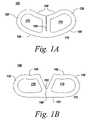
- FIG. 1A-1Billustrate one embodiment of an implant having a flexible joint.
- FIG. 2A-2Billustrate another embodiment of an implant a having a number of flexible joints.
- FIGS. 3A-3Billustrate another embodiment of an implant having another type of flexible joint.
- FIG. 4illustrates a flow diagram for an exemplary embodiment of a method of fusing a spine using the implant of the present invention.
- FIG. 5A-5Billustrate another embodiment of an implant having a number of flexible joints and surface configurations.
- FIG. 6illustrates the deformable nature of the implant of the present invention.
- FIG. 7illustrate an embodiment of the system of the present invention wherein the implant has surface configurations that slidably attach the implant to an insertion guide.
- FIG. 8illustrates a flow diagram for an exemplary embodiment of a method of fusing a spine using the system of the present invention
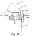
- FIGS. 9A-9Dillustrate one embodiment of how the implant of the system of the present invention is inserted by sliding the implant along the insertion guide as set forth in the exemplary embodiment of the method of FIG. 8 .
- the present inventionprovides an improved surgical implant and method for performing spinal fusion surgery in a patient.
- the implantcomprises a cage having one or more flexible joints.
- the cageis defined by at least a first end, second end, first side, and second side surface.
- the first and second side surfacesextend substantially parallel to each other to span a space between adjoining vertebrae and the first and second ends interconnect the first side surface and the second side surface.
- the one or more flexible jointsallow the cage to be deformed for insertion into a patient.
- the ability to deform the cageallows a greater ease and flexibility in inserting and positioning the implant.
- MISminimally invasive surgery
- the implantmay further have surface configurations for slidably attaching the implant to a guide used to insert the implant. Embodiments of the implant and methods of use are described below.
- FIGS. 1A and 1Bdepict one embodiment of an implant 100 for forming a rigid structure between adjoining vertebrae in a patient.
- the implantcomprises a cage 110 having first end 120 , second end 130 , first side 140 , and second side 150 surfaces.
- the first 140 and second 150 side surfacesextend substantially parallel to each other to span a space between adjoining vertebrae.
- the first 120 and second 130 end surfacesinterconnect said first side surface 140 and second side surface 150 .
- a flexible joint 160is incorporated into the cage allowing the cage to be deformed for insertion into a patient.
- FIG. 1Adepicts the cage 110 of the implant in a rest state.
- the first 140 and second 150 side surfacesare curved giving the cage a curved kidney shape. This curvature and shape provide greater coverage and support then tradition straight-sided implants and is particularly adapted for use in a T-PLIF procedure. While, this shape provides greater biomechanical stability it makes it more difficult to insert and position due to its increased width.
- FIG. 1Bshows the cage 110 in a deformed state wherein the first side surface 140 has been divided or split at the flexible joint 160 giving the cage a substantially straight-sided profile. This allows the cage implant 100 to be used with traditional insertion devices configured to be used with traditional straight-sided implants.
- the cageis designed to provide spacing between adjoining vertebrae while encouraging bone growth.
- the cage 110may be formed of any biocompatible material suitable for surgical implantation in a patient.
- the cageis form of a polymer or composite through a process such as injection molding.
- Bio-compatible metalsmay also be used to add strength or rigidity. Examples of suitable materials include, but are not limited to, PEAK, carbon fiber, titanium, stainless steel, Nitinol, and the like, or any combination thereof.
- the cavities 170 created by the cage 110allow the bone to grow through the cage to fuse the vertebrae.
- a substance, such as bone chips, or bone graftmay be placed in the cavities 170 to encourage bone growth.
- the flexible joint 160comprises a living hinge that is formed as part of the cage during the injection molding process.
- the jointmay not be formed as part of the cage.
- the cagemay comprise two parts that are joined together using a non-unitary joint mechanism that is embedded in or secured to the two parts.
- Other implementations and embodimentswill be apparent to one skilled in the art given the benefit of this disclosure.
- FIGS. 2A and 2Bdepict another embodiment of the implant 200 of the invention.
- this implant 200comprises a cage 210 having first end 220 , second end 230 , first side 240 , and second side 250 surfaces.
- the first 240 and second 250 side surfacesare curved and extend substantially parallel to each other to span a space between adjoining vertebrae.
- the first 220 and second 230 end surfacesinterconnect said first side surface 240 and second side surface 250 providing cavities 270 within the cage 210 .
- multiple flexible joints 260are used to allow the cage to be deformed for insertion into a patient.
- FIG. 1AFIG.
- FIG. 2Adepicts the cage 210 of the implant 200 in a rest state with first 240 and second 250 side surfaces curved to give the cage a curved kidney shape.
- FIG. 2Bshows the cage 210 in a deformed state wherein the first side surface 240 has been divided or split at two flexible joints 160 to give the cage a substantially straight-sided profile.
- the flexible joints 260comprise living hinges that are formed as part of the cage during the injection molding process.
- the flexible joints 260also include a spring mechanism 280 to reinforce the living hinges and return the cage 210 to a rest state after being deformed.
- the spring 280is formed of a piece of metal attached to the cage.
- the spring 280may be formed of plastic or a composite material.
- the spring 280may be embedded in the cage 210 during the formation of the cage 210 , for example, during injection molding.
- the spring 280may be attached to the cage 210 using adhesive, rivets, or other fastening means.
- the spring 280may also serve as the flexible joint 260 .
- Other embodiments and configurationswill be apparent to one skilled in the art given the benefit of this disclosure.
- FIGS. 2A and 2Balso includes an opening 225 in the first end surface 220 for receiving an instrument such as an inserter for attaching the implant to the inserter.
- the opening 225may be in the second end surface 230 or each end surface may have such an opening. Examples of inserters the use of inserters in conjunction with implants can be seen in WO2005077288 A1
- FIGS. 3A-3Bdepict another example of other possible shapes and flexible joints.
- FIGS. 3A and 3Bare a top view depicting a straight sided square shaped implant 300 .
- flexible jointsare used to connect the first 340 and second 350 side surfaces to the first 320 and second 330 end surfaces of the cage 310 .
- Thisallows the cage 310 to be transformed down to a smaller size as shown in FIG. 3B .
- the ability to transform the cage 310allows the cage to be inserted through a smaller access port for insertion in between vertebrae.
- FIG. 4is a flow chart 400 of an exemplary method for fusing vertebrae of a patient.
- the methodinvolves substantially the steps of providing an implant of the present invention (step 420 ) and inserting the implant into the space between adjoining vertebrae in a patient to form a rigid structure between the adjoining vertebrae (step 430 ).
- the method 400may further include the steps of preparing the space between adjoining vertebrae (step 410 ) as well as the steps of transforming the cage of the implant to a smaller profile (step 425 ) before implantation and transforming the cage back to the original profile after insertion ( 435 ).
- the step of preparing the space between adjoining vertebraemay include removing the disk material between the vertebrae. Then the space between the vertebrae may be distracted to relieve pressure from neural elements and provide space for the entry of surgical tools and the insertion of the implant. Preferably the surgery including the insertion is performed using a MIS technique such a T-PLIF procedure.
- the cage of the implantmay need to be transformed or otherwise deformed in order to fit through the access port or window (step 425 ) and be positioned in the space between vertebrae. Once in position, the cage may then be transformed back or otherwise returned to its rest state (step 435 ). In certain embodiments this is performed by a spring incorporated or attached to the one or more flexible joints.
- the implant 500may further include surface configurations 590 on at least one of the first 540 and second 550 side surfaces of the cage 510 for slidably attaching the implant 500 to an insertion guide.
- the surface configurations 590are tabs or fingers formed on the first side surface 540 .
- the flexible joints 560 of the implant 500allow the cage 510 to deform (i.e. straighten) to conform to the shape of the insertion guide. This is described in more detail below.
- the cage 510further includes textured edges 515 on the first end 520 , second end 530 , first side 540 , and second side 550 surfaces for engaging the bone of the adjoining vertebrae to secure the implant in place in the space between vertebrae.
- textured edges 515 on the first end 520 , second end 530 , first side 540 , and second side 550 surfacesfor engaging the bone of the adjoining vertebrae to secure the implant in place in the space between vertebrae.
- Other possible configurations and textures for securing the implant 500will be apparent to one skilled in the art given the benefit of this disclosure.
- FIG. 6depicts one advantage of the cage 510 of the implant being able to deform.
- the ability of the implant 500 of the present invention to deformallows the profile of the cage to be transformed to a smaller profile. When thus transformed, the implant can be passed through a passage smaller than what is required by a traditional curved implant 600 .
- the deformed (compressed) implant 500(including surface configurations) requires only 11.9 mm of space as opposed to the 12.7 mm of space required for a fixed, non-deformable, curved implant 600 of the same size.
- a systemfor forming a rigid structure between adjoining vertebrae in a patient.
- FIG. 7An example of such a system can be seen in FIG. 7 .
- the system 700includes an implant 500 of the present invention as shown in FIGS. 5A and 5B having surface configurations 590 for slidably attaching the implant 500 to an insertion guide 710 .
- the flexible joints 560 of the implantmay allow the cage 510 to conform to the shape of the insertion guide 710 .
- the cage 510is deformed so as to have a smaller straight-sided profile when attached to a straight portion of the insertion guide 710 .
- the insertion guide 710may have a curved end 720 to further assist in the insertion and positioning of the implant 510 .
- the flexible joints 560 of the implant 500allow the implant to curve to conform to the curved end 720 of the insertion guide 710 .
- the implant 500may slide along the insertion guide 710 using an inserter configured to mate with opening 525 .
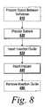
- FIG. 8is a flow chart 800 of an exemplary method for fusing vertebrae of a patient.
- the methodinvolves substantially the steps of providing a system of the present invention having an implant with surface configurations and an insertion guide (Step 820 ), inserting the insertion guide into the space between adjoining vertebrae (Step 830 ), and sliding the implant along the length of the insertion guide to position the implant in the space between adjoining vertebrae, (Step 840 ).
- the method 800may further include the steps of preparing the space between adjoining vertebrae (Step 810 ) as well as the step of removing the insertion guide after the implant has been inserted (Step 850 ).
- the step of preparing the space between adjoining vertebraemay include removing the disk material between the vertebrae. Then the space between the vertebrae may be distracted to relieve pressure from neural elements and provide space for the entry of surgical tools and the insertion of the implant. Preferably the surgery including the insertion is performed using a MIS technique such a T-PLIF procedure.
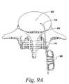
- FIG. 9A-DExamples of this methodology using a T-PLIF technique can be seen in FIG. 9A-D .
- the insertion guide with a curved tip 720is used to deform and guide the implant 500 so as to be inserted into and positioned in the space 920 between vertebrae as seen in FIG. 9A .
- the implantis slid along the length of the insertion guide 710 .
- the implant 600may be slid along the insertion guide 710 using an insertion tool (not shown) mated with the opening 525 configured to receive the insertion tool. Examples of suitable insertion devices and their use is discussed in WO2005077288 A1.
- the insertion guide 710is used to guide the implant 500 through the access window 910 and position the implant in location in the space 920 between vertebrae.
- the use of the curved tip 720allows the implant 510 to be positioned at a desired angle, preferably around 45°, even though the angle of approach through the access window 910 may be closer to 35°.
- the insertion guide 710may be removed and the implant allowed to transform or otherwise return to its rest state as seen in FIG. 9D . In certain embodiments this is performed by a spring incorporated or attached to the one or more flexible joints.
- the apparatus and techniques of the present inventionprovide numerous advantages.
- the implant of the present inventioncan be used in minimally invasive surgery (MIS) wherein the cage can be deformed for easier insertion and positioning through a smaller access port.
- the cagemay have surface configurations for use with an insertion guide.
- the cage of the implantcan be deformed to conform to the shape of the guide which allows for curved guides which in turn provide more accurate insertion and positioning.
Landscapes
- Health & Medical Sciences (AREA)
- Engineering & Computer Science (AREA)
- Biomedical Technology (AREA)
- Orthopedic Medicine & Surgery (AREA)
- Neurology (AREA)
- Transplantation (AREA)
- Heart & Thoracic Surgery (AREA)
- Oral & Maxillofacial Surgery (AREA)
- Cardiology (AREA)
- Vascular Medicine (AREA)
- Life Sciences & Earth Sciences (AREA)
- Animal Behavior & Ethology (AREA)
- General Health & Medical Sciences (AREA)
- Public Health (AREA)
- Veterinary Medicine (AREA)
- Physical Education & Sports Medicine (AREA)
- Prostheses (AREA)
Abstract
Description
Claims (13)
Priority Applications (11)
| Application Number | Priority Date | Filing Date | Title |
|---|---|---|---|
| US11/496,564US8034110B2 (en) | 2006-07-31 | 2006-07-31 | Spinal fusion implant |
| PCT/US2007/017100WO2008016598A2 (en) | 2006-07-31 | 2007-07-31 | Spinal fusion implant |
| EP07836359.5AEP2076221B1 (en) | 2006-07-31 | 2007-07-31 | Spinal fusion implant |
| US13/230,163US8579983B2 (en) | 2006-07-31 | 2011-09-12 | Spinal fusion implant |
| US14/053,821US8936643B2 (en) | 2006-07-31 | 2013-10-15 | Spinal fusion implant |
| US14/574,441US9387091B2 (en) | 2006-07-31 | 2014-12-18 | Spinal fusion implant |
| US14/723,580US9320614B2 (en) | 2006-07-31 | 2015-05-28 | Spinal fusion implant |
| US15/181,542US9713538B2 (en) | 2006-07-31 | 2016-06-14 | Spinal fusion implant |
| US15/332,404US9737413B2 (en) | 2006-07-31 | 2016-10-24 | Spinal fusion implant |
| US15/641,456US10010428B2 (en) | 2006-07-31 | 2017-07-05 | Spinal fusion implant |
| US15/994,249US10695191B2 (en) | 2006-07-31 | 2018-05-31 | Spinal fusion implant |
Applications Claiming Priority (1)
| Application Number | Priority Date | Filing Date | Title |
|---|---|---|---|
| US11/496,564US8034110B2 (en) | 2006-07-31 | 2006-07-31 | Spinal fusion implant |
Related Child Applications (1)
| Application Number | Title | Priority Date | Filing Date |
|---|---|---|---|
| US13/230,163ContinuationUS8579983B2 (en) | 2006-07-31 | 2011-09-12 | Spinal fusion implant |
Publications (2)
| Publication Number | Publication Date |
|---|---|
| US20080058933A1 US20080058933A1 (en) | 2008-03-06 |
| US8034110B2true US8034110B2 (en) | 2011-10-11 |
Family
ID=38997675
Family Applications (9)
| Application Number | Title | Priority Date | Filing Date |
|---|---|---|---|
| US11/496,564Active2027-06-13US8034110B2 (en) | 2006-07-31 | 2006-07-31 | Spinal fusion implant |
| US13/230,163Active2026-08-24US8579983B2 (en) | 2006-07-31 | 2011-09-12 | Spinal fusion implant |
| US14/053,821ActiveUS8936643B2 (en) | 2006-07-31 | 2013-10-15 | Spinal fusion implant |
| US14/574,441ActiveUS9387091B2 (en) | 2006-07-31 | 2014-12-18 | Spinal fusion implant |
| US14/723,580ActiveUS9320614B2 (en) | 2006-07-31 | 2015-05-28 | Spinal fusion implant |
| US15/181,542ActiveUS9713538B2 (en) | 2006-07-31 | 2016-06-14 | Spinal fusion implant |
| US15/332,404ActiveUS9737413B2 (en) | 2006-07-31 | 2016-10-24 | Spinal fusion implant |
| US15/641,456ActiveUS10010428B2 (en) | 2006-07-31 | 2017-07-05 | Spinal fusion implant |
| US15/994,249Active2027-01-16US10695191B2 (en) | 2006-07-31 | 2018-05-31 | Spinal fusion implant |
Family Applications After (8)
| Application Number | Title | Priority Date | Filing Date |
|---|---|---|---|
| US13/230,163Active2026-08-24US8579983B2 (en) | 2006-07-31 | 2011-09-12 | Spinal fusion implant |
| US14/053,821ActiveUS8936643B2 (en) | 2006-07-31 | 2013-10-15 | Spinal fusion implant |
| US14/574,441ActiveUS9387091B2 (en) | 2006-07-31 | 2014-12-18 | Spinal fusion implant |
| US14/723,580ActiveUS9320614B2 (en) | 2006-07-31 | 2015-05-28 | Spinal fusion implant |
| US15/181,542ActiveUS9713538B2 (en) | 2006-07-31 | 2016-06-14 | Spinal fusion implant |
| US15/332,404ActiveUS9737413B2 (en) | 2006-07-31 | 2016-10-24 | Spinal fusion implant |
| US15/641,456ActiveUS10010428B2 (en) | 2006-07-31 | 2017-07-05 | Spinal fusion implant |
| US15/994,249Active2027-01-16US10695191B2 (en) | 2006-07-31 | 2018-05-31 | Spinal fusion implant |
Country Status (3)
| Country | Link |
|---|---|
| US (9) | US8034110B2 (en) |
| EP (1) | EP2076221B1 (en) |
| WO (1) | WO2008016598A2 (en) |
Cited By (63)
| Publication number | Priority date | Publication date | Assignee | Title |
|---|---|---|---|---|
| US20100191337A1 (en)* | 2006-03-08 | 2010-07-29 | Seaspine, Inc. | Interbody device for spinal applications |
| US20100198263A1 (en)* | 2007-08-09 | 2010-08-05 | Nonlinear Technologies Ltd. | Device and method for spinous process distraction |
| US20130138214A1 (en)* | 2010-05-27 | 2013-05-30 | Flexmedex, LLC | Support device and method of use |
| US20140046446A1 (en)* | 2012-08-08 | 2014-02-13 | James C. Robinson | Percutaneous cage delivery systems devices and methods |
| US20140135935A1 (en)* | 2007-06-15 | 2014-05-15 | Ldr Medical | Nucleus Prosthesis |
| US20140379086A1 (en)* | 2011-09-20 | 2014-12-25 | The University Of Toledo | Expandable Inter-Vertebral Cage and Method of Installing Same |
| US8936643B2 (en) | 2006-07-31 | 2015-01-20 | DePuy Synthes Products, LLC | Spinal fusion implant |
| US9050112B2 (en) | 2011-08-23 | 2015-06-09 | Flexmedex, LLC | Tissue removal device and method |
| US9216096B2 (en) | 2010-03-16 | 2015-12-22 | Pinnacle Spine Group, Llc | Intervertebral implants and related tools |
| US9259329B2 (en) | 2004-09-21 | 2016-02-16 | Stout Medical Group, L.P. | Expandable support device and method of use |
| US9289240B2 (en) | 2005-12-23 | 2016-03-22 | DePuy Synthes Products, Inc. | Flexible elongated chain implant and method of supporting body tissue with same |
| US9380932B1 (en) | 2011-11-02 | 2016-07-05 | Pinnacle Spine Group, Llc | Retractor devices for minimally invasive access to the spine |
| US9421056B2 (en) | 2007-09-28 | 2016-08-23 | DePuy Synthes Products, Inc. | Balloon with shape control for spinal procedures |
| US9592063B2 (en) | 2010-06-24 | 2017-03-14 | DePuy Synthes Products, Inc. | Universal trial for lateral cages |
| US9592132B2 (en) | 2015-01-09 | 2017-03-14 | Shape Memory Orthopedics | Shape-memory spinal fusion system |
| US9770339B2 (en) | 2005-07-14 | 2017-09-26 | Stout Medical Group, L.P. | Expandable support device and method of use |
| US9931224B2 (en) | 2009-11-05 | 2018-04-03 | DePuy Synthes Products, Inc. | Self-pivoting spinal implant and associated instrumentation |
| US10022245B2 (en) | 2012-12-17 | 2018-07-17 | DePuy Synthes Products, Inc. | Polyaxial articulating instrument |
| US10070968B2 (en) | 2010-08-24 | 2018-09-11 | Flexmedex, LLC | Support device and method for use |
| US10070970B2 (en) | 2013-03-14 | 2018-09-11 | Pinnacle Spine Group, Llc | Interbody implants and graft delivery systems |
| US10070969B2 (en) | 2013-01-17 | 2018-09-11 | Stryker European Holdings I, Llc | Annulus plug for intervertebral disc repair |
| US10285819B2 (en) | 2008-11-12 | 2019-05-14 | Stout Medical Group, L.P. | Fixation device and method |
| US10537435B2 (en) | 2007-05-17 | 2020-01-21 | DePuy Synthes Products, Inc. | Self-distracting cage |
| US10617530B2 (en) | 2011-07-14 | 2020-04-14 | Seaspine, Inc. | Laterally deflectable implant |
| US10744000B1 (en) | 2016-10-25 | 2020-08-18 | Samy Abdou | Devices and methods for vertebral bone realignment |
| US10758289B2 (en) | 2006-05-01 | 2020-09-01 | Stout Medical Group, L.P. | Expandable support device and method of use |
| US10857004B2 (en)* | 2009-12-07 | 2020-12-08 | Samy Abdou | Devices and methods for minimally invasive spinal stabilization and instrumentation |
| US10940014B2 (en) | 2008-11-12 | 2021-03-09 | Stout Medical Group, L.P. | Fixation device and method |
| US10966843B2 (en) | 2017-07-18 | 2021-04-06 | DePuy Synthes Products, Inc. | Implant inserters and related methods |
| US10973648B1 (en) | 2016-10-25 | 2021-04-13 | Samy Abdou | Devices and methods for vertebral bone realignment |
| US11006982B2 (en) | 2012-02-22 | 2021-05-18 | Samy Abdou | Spinous process fixation devices and methods of use |
| US11045331B2 (en) | 2017-08-14 | 2021-06-29 | DePuy Synthes Products, Inc. | Intervertebral implant inserters and related methods |
| US20210236300A1 (en)* | 2020-02-05 | 2021-08-05 | K2M, Inc. | Flexible Interbody Implant |
| US11096799B2 (en) | 2004-11-24 | 2021-08-24 | Samy Abdou | Devices and methods for inter-vertebral orthopedic device placement |
| WO2021216856A1 (en) | 2020-04-23 | 2021-10-28 | Rv Medical Llc | Screwless interbody device for spinal surgery |
| US11173040B2 (en)* | 2012-10-22 | 2021-11-16 | Cogent Spine, LLC | Devices and methods for spinal stabilization and instrumentation |
| US11179248B2 (en) | 2018-10-02 | 2021-11-23 | Samy Abdou | Devices and methods for spinal implantation |
| US11246718B2 (en) | 2015-10-14 | 2022-02-15 | Samy Abdou | Devices and methods for vertebral stabilization |
| US11324608B2 (en) | 2011-09-23 | 2022-05-10 | Samy Abdou | Spinal fixation devices and methods of use |
| US11344424B2 (en) | 2017-06-14 | 2022-05-31 | Medos International Sarl | Expandable intervertebral implant and related methods |
| US11369490B2 (en) | 2011-03-22 | 2022-06-28 | DePuy Synthes Products, Inc. | Universal trial for lateral cages |
| US11426290B2 (en) | 2015-03-06 | 2022-08-30 | DePuy Synthes Products, Inc. | Expandable intervertebral implant, system, kit and method |
| US11432942B2 (en) | 2006-12-07 | 2022-09-06 | DePuy Synthes Products, Inc. | Intervertebral implant |
| US11446155B2 (en) | 2017-05-08 | 2022-09-20 | Medos International Sarl | Expandable cage |
| US11446156B2 (en) | 2018-10-25 | 2022-09-20 | Medos International Sarl | Expandable intervertebral implant, inserter instrument, and related methods |
| US11452607B2 (en) | 2010-10-11 | 2022-09-27 | DePuy Synthes Products, Inc. | Expandable interspinous process spacer implant |
| US11497619B2 (en) | 2013-03-07 | 2022-11-15 | DePuy Synthes Products, Inc. | Intervertebral implant |
| US11510788B2 (en) | 2016-06-28 | 2022-11-29 | Eit Emerging Implant Technologies Gmbh | Expandable, angularly adjustable intervertebral cages |
| US11559336B2 (en) | 2012-08-28 | 2023-01-24 | Samy Abdou | Spinal fixation devices and methods of use |
| US11596522B2 (en) | 2016-06-28 | 2023-03-07 | Eit Emerging Implant Technologies Gmbh | Expandable and angularly adjustable intervertebral cages with articulating joint |
| US11602438B2 (en) | 2008-04-05 | 2023-03-14 | DePuy Synthes Products, Inc. | Expandable intervertebral implant |
| US11607321B2 (en) | 2009-12-10 | 2023-03-21 | DePuy Synthes Products, Inc. | Bellows-like expandable interbody fusion cage |
| US11612491B2 (en) | 2009-03-30 | 2023-03-28 | DePuy Synthes Products, Inc. | Zero profile spinal fusion cage |
| US11622868B2 (en) | 2007-06-26 | 2023-04-11 | DePuy Synthes Products, Inc. | Highly lordosed fusion cage |
| US11737881B2 (en) | 2008-01-17 | 2023-08-29 | DePuy Synthes Products, Inc. | Expandable intervertebral implant and associated method of manufacturing the same |
| US11752009B2 (en) | 2021-04-06 | 2023-09-12 | Medos International Sarl | Expandable intervertebral fusion cage |
| US11806245B2 (en) | 2020-03-06 | 2023-11-07 | Eit Emerging Implant Technologies Gmbh | Expandable intervertebral implant |
| US11850160B2 (en) | 2021-03-26 | 2023-12-26 | Medos International Sarl | Expandable lordotic intervertebral fusion cage |
| US11872139B2 (en) | 2010-06-24 | 2024-01-16 | DePuy Synthes Products, Inc. | Enhanced cage insertion assembly |
| USRE49973E1 (en) | 2013-02-28 | 2024-05-21 | DePuy Synthes Products, Inc. | Expandable intervertebral implant, system, kit and method |
| US12090064B2 (en) | 2022-03-01 | 2024-09-17 | Medos International Sarl | Stabilization members for expandable intervertebral implants, and related systems and methods |
| USD1095838S1 (en) | 2021-10-15 | 2025-09-30 | Rv Medical Llc | Interbody device |
| US12440346B2 (en) | 2023-03-31 | 2025-10-14 | DePuy Synthes Products, Inc. | Expandable intervertebral implant |
Families Citing this family (31)
| Publication number | Priority date | Publication date | Assignee | Title |
|---|---|---|---|---|
| US7267687B2 (en)* | 2001-10-02 | 2007-09-11 | Rex Medical, L.P | Spinal implant and method of use |
| US8623088B1 (en) | 2005-07-15 | 2014-01-07 | Nuvasive, Inc. | Spinal fusion implant and related methods |
| USD741488S1 (en) | 2006-07-17 | 2015-10-20 | Nuvasive, Inc. | Spinal fusion implant |
| CA2668655A1 (en) | 2006-11-16 | 2008-05-29 | Rex Medical, L.P. | Spinal implant and method of use |
| US20080255664A1 (en) | 2007-04-10 | 2008-10-16 | Mdesign International | Percutaneously deliverable orthopedic joint device |
| EP2208481B1 (en)* | 2007-07-27 | 2016-12-28 | R Tree Innovations, LLC | Inter-Body Implantation System |
| US9101491B2 (en) | 2007-12-28 | 2015-08-11 | Nuvasive, Inc. | Spinal surgical implant and related methods |
| US8216317B2 (en) | 2008-03-31 | 2012-07-10 | Stryker Spine | Spinal implant apparatus and methods |
| KR20120013940A (en)* | 2009-04-15 | 2012-02-15 | 신세스 게엠바하 | Spinal Implant System for Flexible Intervertebral Spacer |
| ES2563172T3 (en)* | 2009-07-09 | 2016-03-11 | R Tree Innovations, Llc | Flexible intersomatic implant |
| US20110029083A1 (en)* | 2009-07-31 | 2011-02-03 | Warsaw Orthopedic, Inc. | Flexible Spinal Implant |
| JP2013504389A (en) | 2009-09-11 | 2013-02-07 | アーティキュリンクス, インコーポレイテッド | Disc-shaped orthopedic device |
| USD731063S1 (en) | 2009-10-13 | 2015-06-02 | Nuvasive, Inc. | Spinal fusion implant |
| FR2958151B1 (en)* | 2010-04-06 | 2012-04-27 | Hassan Razian | SYSTEM FOR REPLACING AN INTERVERTEBRAL DISC. |
| US20110264219A1 (en)* | 2010-04-22 | 2011-10-27 | Rouben David P | Spacer for spinal fusion |
| US8623091B2 (en) | 2010-06-29 | 2014-01-07 | DePuy Synthes Products, LLC | Distractible intervertebral implant |
| EP3017793A3 (en) | 2010-07-15 | 2016-08-17 | Spine Wave, Inc. | A plastically deformable inter-osseous device |
| EP2618788B1 (en)* | 2010-09-23 | 2017-12-20 | DePuy Synthes Products, LLC | Multi-segment lateral cages adapted to flex substantially in the coronal plane |
| US8858637B2 (en) | 2010-09-30 | 2014-10-14 | Stryker Spine | Surgical implant with guiding rail |
| US8603175B2 (en) | 2010-09-30 | 2013-12-10 | Stryker Spine | Method of inserting surgical implant with guiding rail |
| US8425529B2 (en) | 2010-09-30 | 2013-04-23 | Stryker Spine | Instrument for inserting surgical implant with guiding rail |
| KR101877806B1 (en)* | 2010-10-05 | 2018-07-12 | 모건 피. 로리오 | Minimally invasive intervertebral systems and methods |
| US9149286B1 (en) | 2010-11-12 | 2015-10-06 | Flexmedex, LLC | Guidance tool and method for use |
| US8512408B2 (en) | 2010-12-17 | 2013-08-20 | Warsaw Orthopedic, Inc. | Flexiable spinal implant |
| FR2981262B1 (en)* | 2011-10-14 | 2014-09-19 | Pierre Roussouly | INTERSOMATIC IMPLANT |
| US9226764B2 (en) | 2012-03-06 | 2016-01-05 | DePuy Synthes Products, Inc. | Conformable soft tissue removal instruments |
| US9532881B2 (en) | 2012-08-12 | 2017-01-03 | Brian Albert Hauck | Memory material implant system and methods of use |
| US10478313B1 (en) | 2014-01-10 | 2019-11-19 | Nuvasive, Inc. | Spinal fusion implant and related methods |
| US9730802B1 (en) | 2014-01-14 | 2017-08-15 | Nuvasive, Inc. | Spinal fusion implant and related methods |
| FR3091648B1 (en) | 2019-01-10 | 2020-12-25 | Razian Hassan | Intervertebral cage |
| JP6700511B1 (en)* | 2019-08-30 | 2020-05-27 | リーガエース株式会社 | System for guiding interbody spacers between bodies |
Citations (21)
| Publication number | Priority date | Publication date | Assignee | Title |
|---|---|---|---|---|
| US4743256A (en) | 1985-10-04 | 1988-05-10 | Brantigan John W | Surgical prosthetic implant facilitating vertebral interbody fusion and method |
| US4834757A (en) | 1987-01-22 | 1989-05-30 | Brantigan John W | Prosthetic implant |
| US5192327A (en) | 1991-03-22 | 1993-03-09 | Brantigan John W | Surgical prosthetic implant for vertebrae |
| US5425772A (en) | 1993-09-20 | 1995-06-20 | Brantigan; John W. | Prosthetic implant for intervertebral spinal fusion |
| US5554191A (en)* | 1994-01-26 | 1996-09-10 | Biomat | Intersomatic vertebral cage |
| US5716415A (en) | 1993-10-01 | 1998-02-10 | Acromed Corporation | Spinal implant |
| US5984922A (en) | 1993-07-09 | 1999-11-16 | Mckay; Douglas William | Spinal fixation device and method |
| US6039761A (en)* | 1997-02-12 | 2000-03-21 | Li Medical Technologies, Inc. | Intervertebral spacer and tool and method for emplacement thereof |
| US6193757B1 (en)* | 1998-10-29 | 2001-02-27 | Sdgi Holdings, Inc. | Expandable intervertebral spacers |
| US6206923B1 (en)* | 1999-01-08 | 2001-03-27 | Sdgi Holdings, Inc. | Flexible implant using partially demineralized bone |
| US6245108B1 (en) | 1999-02-25 | 2001-06-12 | Spineco | Spinal fusion implant |
| US6325827B1 (en)* | 1999-02-01 | 2001-12-04 | Blacksheep Technologies, Inc. | Intervertebral implant |
| US6387130B1 (en)* | 1999-04-16 | 2002-05-14 | Nuvasive, Inc. | Segmented linked intervertebral implant systems |
| US20030093153A1 (en)* | 2001-09-28 | 2003-05-15 | Banick Christopher M. | Skeletal stabilization implant |
| US6689132B2 (en)* | 2002-05-15 | 2004-02-10 | Spineco, Inc. | Spinal implant insertion tool |
| US6719794B2 (en)* | 2001-05-03 | 2004-04-13 | Synthes (U.S.A.) | Intervertebral implant for transforaminal posterior lumbar interbody fusion procedure |
| US20040127990A1 (en)* | 2002-12-31 | 2004-07-01 | Bartish, Charles M. | Novel banana cage |
| WO2005077288A1 (en) | 2004-02-09 | 2005-08-25 | Depuy Spine, Inc. | Systems and methods for spinal surgery |
| US6974480B2 (en) | 2001-05-03 | 2005-12-13 | Synthes (Usa) | Intervertebral implant for transforaminal posterior lumbar interbody fusion procedure |
| US20060142858A1 (en)* | 2004-12-16 | 2006-06-29 | Dennis Colleran | Expandable implants for spinal disc replacement |
| US7520900B2 (en)* | 2000-08-30 | 2009-04-21 | Warsaw Orthopedic, Inc. | Intervertebral disc nucleus implants and methods |
Family Cites Families (179)
| Publication number | Priority date | Publication date | Assignee | Title |
|---|---|---|---|---|
| US2170111A (en) | 1936-05-28 | 1939-08-22 | Rohm & Haas | Manufacture of amines |
| NL45585C (en) | 1936-05-28 | 1900-01-01 | ||
| US2229024A (en) | 1939-05-23 | 1941-01-21 | Rohm & Haas | Aromatic ether of polyalkoxyalkylalkylene polyamines and process for obtaining them |
| US2826532A (en) | 1952-04-15 | 1958-03-11 | Gen Aniline & Film Corp | Process of stabilizing polyvinyl pyrrolidone-iodine compositions |
| US2900305A (en) | 1952-04-15 | 1959-08-18 | Gen Aniline & Film Corp | Preparation of iodine polyvinylpyrrolidone adducts |
| BE615889A (en) | 1952-04-15 | 1900-01-01 | ||
| US2710277A (en) | 1952-04-23 | 1955-06-07 | West Laboratories Inc | Iodine phosphate ester compositions |
| US2977315A (en) | 1956-09-12 | 1961-03-28 | Lazarus Lab Inc | Water soluble iodine-phosphoric-acidsynthetic detergent composition |
| US3228828A (en) | 1963-02-15 | 1966-01-11 | Standard Naphthalene Products | Insecticide composition comprising naphthalene and paraffinic hydrocarbon |
| SU557755A3 (en) | 1968-08-19 | 1977-05-05 | Янссен Фармасьютика Н.В. (Фирма) | Method for preparing imidazole derivatives |
| US4352883A (en) | 1979-03-28 | 1982-10-05 | Damon Corporation | Encapsulation of biological material |
| US4440921A (en) | 1982-06-21 | 1984-04-03 | Research Corporation | Coupling of polyorganophosphazenes to carboxylic acid |
| US4495174A (en) | 1982-06-21 | 1985-01-22 | Research Corporation | Anesthetic polyorganophosphazenes |
| US4645503A (en) | 1985-08-27 | 1987-02-24 | Orthomatrix Inc. | Moldable bone-implant material |
| US5133755A (en) | 1986-01-28 | 1992-07-28 | Thm Biomedical, Inc. | Method and apparatus for diodegradable, osteogenic, bone graft substitute device |
| US4880622A (en) | 1986-05-20 | 1989-11-14 | Research Corporation Technologies, Inc. | Water-soluble phosphazene polymers having pharmacological applications |
| US4871366A (en) | 1986-05-27 | 1989-10-03 | Clemson University | Soft tissue implants for promoting tissue adhesion to same |
| GB8620937D0 (en) | 1986-08-29 | 1986-10-08 | Shepperd J A N | Spinal implant |
| US4772287A (en) | 1987-08-20 | 1988-09-20 | Cedar Surgical, Inc. | Prosthetic disc and method of implanting |
| CA1333209C (en) | 1988-06-28 | 1994-11-29 | Gary Karlin Michelson | Artificial spinal fusion implants |
| US5059193A (en) | 1989-11-20 | 1991-10-22 | Spine-Tech, Inc. | Expandable spinal implant and surgical method |
| US6203565B1 (en) | 1990-06-28 | 2001-03-20 | Peter M. Bonutti | Surgical devices assembled using heat bondable materials |
| US5410016A (en) | 1990-10-15 | 1995-04-25 | Board Of Regents, The University Of Texas System | Photopolymerizable biodegradable hydrogels as tissue contacting materials and controlled-release carriers |
| US6197325B1 (en) | 1990-11-27 | 2001-03-06 | The American National Red Cross | Supplemented and unsupplemented tissue sealants, methods of their production and use |
| US5390683A (en) | 1991-02-22 | 1995-02-21 | Pisharodi; Madhavan | Spinal implantation methods utilizing a middle expandable implant |
| US5123926A (en) | 1991-02-22 | 1992-06-23 | Madhavan Pisharodi | Artificial spinal prosthesis |
| WO1993002021A1 (en) | 1991-07-23 | 1993-02-04 | Tri-Tex Australia Pty Ltd | Non-bituminous sound deadening material |
| DE4131943C1 (en) | 1991-09-25 | 1992-09-17 | Georg 8386 Reisbach De Aigner | |
| NL9200288A (en) | 1992-02-17 | 1993-09-16 | Acromed Bv | DEVICE FOR FIXING AT LEAST A PART OF THE CERVICAL AND / OR THORACAL SPIRIT COLUMN. |
| ES2153378T3 (en) | 1992-02-28 | 2001-03-01 | Univ Texas | PHOTOPOLIMERIZABLE BIODEGRADABLE HYDROGELS AS FABRIC CONTACT MATERIALS AND CONTROLLED DISCHARGE CARRIER. |
| US5985307A (en) | 1993-04-14 | 1999-11-16 | Emory University | Device and method for non-occlusive localized drug delivery |
| US5522895A (en) | 1993-07-23 | 1996-06-04 | Rice University | Biodegradable bone templates |
| US5443514A (en) | 1993-10-01 | 1995-08-22 | Acromed Corporation | Method for using spinal implants |
| US5397364A (en) | 1993-10-12 | 1995-03-14 | Danek Medical, Inc. | Anterior interbody fusion device |
| US5888220A (en) | 1994-05-06 | 1999-03-30 | Advanced Bio Surfaces, Inc. | Articulating joint repair |
| US6248131B1 (en) | 1994-05-06 | 2001-06-19 | Advanced Bio Surfaces, Inc. | Articulating joint repair |
| US5571189A (en) | 1994-05-20 | 1996-11-05 | Kuslich; Stephen D. | Expandable fabric implant for stabilizing the spinal motion segment |
| AU2621295A (en) | 1994-05-24 | 1995-12-18 | Smith & Nephew Plc | Intervertebral disc implant |
| US5562736A (en) | 1994-10-17 | 1996-10-08 | Raymedica, Inc. | Method for surgical implantation of a prosthetic spinal disc nucleus |
| AU3795395A (en) | 1994-11-30 | 1996-06-06 | Ethicon Inc. | Hard tissue bone cements and substitutes |
| US5665122A (en) | 1995-01-31 | 1997-09-09 | Kambin; Parviz | Expandable intervertebral cage and surgical method |
| US5860973A (en) | 1995-02-27 | 1999-01-19 | Michelson; Gary Karlin | Translateral spinal implant |
| US6147168A (en) | 1995-03-06 | 2000-11-14 | Ethicon, Inc. | Copolymers of absorbable polyoxaesters |
| US5658335A (en) | 1995-03-09 | 1997-08-19 | Cohort Medical Products Group, Inc. | Spinal fixator |
| US6027742A (en) | 1995-05-19 | 2000-02-22 | Etex Corporation | Bioresorbable ceramic composites |
| US5676976A (en) | 1995-05-19 | 1997-10-14 | Etex Corporation | Synthesis of reactive amorphous calcium phosphates |
| US5833657A (en) | 1995-05-30 | 1998-11-10 | Ethicon, Inc. | Single-walled balloon catheter with non-linear compliance characteristic |
| US5702449A (en) | 1995-06-07 | 1997-12-30 | Danek Medical, Inc. | Reinforced porous spinal implants |
| US6113624A (en) | 1995-10-02 | 2000-09-05 | Ethicon, Inc. | Absorbable elastomeric polymer |
| KR100415064B1 (en) | 1995-10-20 | 2005-04-06 | 신테스 아게 츄어 | Intervertebral implant |
| DE59510855D1 (en) | 1995-11-08 | 2004-03-18 | Ct Pulse Orthopedics Ltd | Intervertebral prosthesis |
| US5807327A (en) | 1995-12-08 | 1998-09-15 | Ethicon, Inc. | Catheter assembly |
| US5824084A (en) | 1996-07-03 | 1998-10-20 | The Cleveland Clinic Foundation | Method of preparing a composite bone graft |
| FR2753368B1 (en) | 1996-09-13 | 1999-01-08 | Chauvin Jean Luc | EXPANSIONAL OSTEOSYNTHESIS CAGE |
| US5782832A (en) | 1996-10-01 | 1998-07-21 | Surgical Dynamics, Inc. | Spinal fusion implant and method of insertion thereof |
| EP0873145A2 (en) | 1996-11-15 | 1998-10-28 | Advanced Bio Surfaces, Inc. | Biomaterial system for in situ tissue repair |
| US5836948A (en) | 1997-01-02 | 1998-11-17 | Saint Francis Medical Technologies, Llc | Spine distraction implant and method |
| US6083522A (en) | 1997-01-09 | 2000-07-04 | Neucoll, Inc. | Devices for tissue repair and methods for preparation and use thereof |
| US5866165A (en) | 1997-01-15 | 1999-02-02 | Orquest, Inc. | Collagen-polysaccharide matrix for bone and cartilage repair |
| WO1998034552A1 (en) | 1997-02-06 | 1998-08-13 | Surgical Dynamics | Expandable non-threaded spinal fusion device |
| DE19710392C1 (en) | 1997-03-13 | 1999-07-01 | Haehnel Michael | Slipped disc implant comprises an extensible, hinged or wound body |
| US6071982A (en) | 1997-04-18 | 2000-06-06 | Cambridge Scientific, Inc. | Bioerodible polymeric semi-interpenetrating network alloys for surgical plates and bone cements, and method for making same |
| US5800549A (en) | 1997-04-30 | 1998-09-01 | Howmedica Inc. | Method and apparatus for injecting an elastic spinal implant |
| US6045579A (en) | 1997-05-01 | 2000-04-04 | Spinal Concepts, Inc. | Adjustable height fusion device |
| CA2328229C (en) | 1997-07-09 | 2007-04-17 | Tegementa, L.L.C. | Interbody device and method for treatment of osteoporotic vertebral collapse |
| US5837752A (en) | 1997-07-17 | 1998-11-17 | Massachusetts Institute Of Technology | Semi-interpenetrating polymer networks |
| US6241771B1 (en) | 1997-08-13 | 2001-06-05 | Cambridge Scientific, Inc. | Resorbable interbody spinal fusion devices |
| US5865848A (en) | 1997-09-12 | 1999-02-02 | Artifex, Ltd. | Dynamic intervertebral spacer and method of use |
| US5824094A (en) | 1997-10-17 | 1998-10-20 | Acromed Corporation | Spinal disc |
| AT405367B (en) | 1998-01-23 | 1999-07-26 | Fuss Franz K Dipl Biomech Dr | Implant |
| US7087082B2 (en) | 1998-08-03 | 2006-08-08 | Synthes (Usa) | Bone implants with central chambers |
| DE19807236C2 (en) | 1998-02-20 | 2000-06-21 | Biedermann Motech Gmbh | Intervertebral implant |
| US6224631B1 (en) | 1998-03-20 | 2001-05-01 | Sulzer Spine-Tech Inc. | Intervertebral implant with reduced contact area and method |
| US6835208B2 (en) | 1998-03-30 | 2004-12-28 | J. Alexander Marchosky | Prosthetic system |
| WO1999049818A1 (en) | 1998-03-30 | 1999-10-07 | Marchosky J Alexander | Prosthetic system |
| US6171610B1 (en) | 1998-04-24 | 2001-01-09 | University Of Massachusetts | Guided development and support of hydrogel-cell compositions |
| US6368325B1 (en) | 1998-05-27 | 2002-04-09 | Nuvasive, Inc. | Bone blocks and methods for inserting bone blocks into intervertebral spaces |
| US6126689A (en) | 1998-06-15 | 2000-10-03 | Expanding Concepts, L.L.C. | Collapsible and expandable interbody fusion device |
| FR2782632B1 (en) | 1998-08-28 | 2000-12-29 | Materiel Orthopedique En Abreg | EXPANSIBLE INTERSOMATIC FUSION CAGE |
| US6165486A (en) | 1998-11-19 | 2000-12-26 | Carnegie Mellon University | Biocompatible compositions and methods of using same |
| US6147135A (en) | 1998-12-31 | 2000-11-14 | Ethicon, Inc. | Fabrication of biocompatible polymeric composites |
| DE19903762C1 (en) | 1999-01-30 | 2000-11-16 | Aesculap Ag & Co Kg | Surgical instrument for inserting intervertebral implants |
| US8133421B2 (en) | 1999-02-23 | 2012-03-13 | Warsaw Orthopedic, Inc. | Methods of making shaped load-bearing osteoimplant |
| US6113638A (en) | 1999-02-26 | 2000-09-05 | Williams; Lytton A. | Method and apparatus for intervertebral implant anchorage |
| CA2363254C (en) | 1999-03-07 | 2009-05-05 | Discure Ltd. | Method and apparatus for computerized surgery |
| US6805697B1 (en) | 1999-05-07 | 2004-10-19 | University Of Virginia Patent Foundation | Method and system for fusing a spinal region |
| FR2794362B1 (en) | 1999-06-02 | 2001-09-21 | Henry Graf | INTERVERTEBRAL IMPLANT AND POSITIONING ASSEMBLY OF SUCH AN IMPLANT |
| US6277149B1 (en) | 1999-06-08 | 2001-08-21 | Osteotech, Inc. | Ramp-shaped intervertebral implant |
| US6264695B1 (en) | 1999-09-30 | 2001-07-24 | Replication Medical, Inc. | Spinal nucleus implant |
| US6494883B1 (en) | 2000-05-26 | 2002-12-17 | Bret A. Ferree | Bone reinforcers |
| US6592625B2 (en) | 1999-10-20 | 2003-07-15 | Anulex Technologies, Inc. | Spinal disc annulus reconstruction method and spinal disc annulus stent |
| US6648915B2 (en) | 1999-12-23 | 2003-11-18 | John A. Sazy | Intervertebral cage and method of use |
| US6899716B2 (en) | 2000-02-16 | 2005-05-31 | Trans1, Inc. | Method and apparatus for spinal augmentation |
| US6740093B2 (en) | 2000-02-28 | 2004-05-25 | Stephen Hochschuler | Method and apparatus for treating a vertebral body |
| US6332894B1 (en) | 2000-03-07 | 2001-12-25 | Zimmer, Inc. | Polymer filled spinal fusion cage |
| US6482234B1 (en) | 2000-04-26 | 2002-11-19 | Pearl Technology Holdings, Llc | Prosthetic spinal disc |
| US6964667B2 (en) | 2000-06-23 | 2005-11-15 | Sdgi Holdings, Inc. | Formed in place fixation system with thermal acceleration |
| CN1192750C (en) | 2000-08-28 | 2005-03-16 | 迪斯科动力学公司 | Prosthesis of vertebral disc |
| CA2429149C (en) | 2000-12-15 | 2010-08-24 | Spineology, Inc. | Annulus-reinforcing band |
| US20020193883A1 (en) | 2001-01-25 | 2002-12-19 | Wironen John F. | Injectable porous bone graft materials |
| US6595998B2 (en) | 2001-03-08 | 2003-07-22 | Spinewave, Inc. | Tissue distraction device |
| US6849093B2 (en) | 2001-03-09 | 2005-02-01 | Gary K. Michelson | Expansion constraining member adapted for use with an expandable interbody spinal fusion implant and method for use thereof |
| US6368351B1 (en) | 2001-03-27 | 2002-04-09 | Bradley J. Glenn | Intervertebral space implant for use in spinal fusion procedures |
| ATE278427T1 (en) | 2001-04-02 | 2004-10-15 | Stratec Medical Ag | BIOACTIVE SURFACE LAYER, ESPECIALLY FOR MEDICAL IMPLANTS AND PROStheses |
| US6632235B2 (en) | 2001-04-19 | 2003-10-14 | Synthes (U.S.A.) | Inflatable device and method for reducing fractures in bone and in treating the spine |
| EP2055267B1 (en) | 2001-05-01 | 2013-04-17 | Amedica Corporation | Radiolucent bone graft |
| US6558424B2 (en) | 2001-06-28 | 2003-05-06 | Depuy Acromed | Modular anatomic fusion device |
| US20040220669A1 (en) | 2001-06-27 | 2004-11-04 | Armin Studer | Intervertebral disk prosthesis |
| US7156877B2 (en) | 2001-06-29 | 2007-01-02 | The Regents Of The University Of California | Biodegradable/bioactive nucleus pulposus implant and method for treating degenerated intervertebral discs |
| US6987136B2 (en) | 2001-07-13 | 2006-01-17 | Vita Special Purpose Corporation | Bioactive spinal implant material and method of manufacture thereof |
| US20030028251A1 (en) | 2001-07-30 | 2003-02-06 | Mathews Hallett H. | Methods and devices for interbody spinal stabilization |
| US6375682B1 (en) | 2001-08-06 | 2002-04-23 | Lewis W. Fleischmann | Collapsible, rotatable and expandable spinal hydraulic prosthetic device |
| US6648917B2 (en) | 2001-10-17 | 2003-11-18 | Medicinelodge, Inc. | Adjustable bone fusion implant and method |
| US8025684B2 (en) | 2001-11-09 | 2011-09-27 | Zimmer Spine, Inc. | Instruments and methods for inserting a spinal implant |
| US20050261682A1 (en) | 2002-04-13 | 2005-11-24 | Ferree Bret A | Vertebral shock absorbers |
| US7582058B1 (en) | 2002-06-26 | 2009-09-01 | Nuvasive, Inc. | Surgical access system and related methods |
| US6793678B2 (en) | 2002-06-27 | 2004-09-21 | Depuy Acromed, Inc. | Prosthetic intervertebral motion disc having dampening |
| US20040087947A1 (en) | 2002-08-28 | 2004-05-06 | Roy Lim | Minimally invasive expanding spacer and method |
| US20040049270A1 (en) | 2002-09-10 | 2004-03-11 | Gewirtz Robert J. | Bone graft device |
| EP1542616B1 (en) | 2002-09-20 | 2015-04-22 | Endologix, Inc. | Stent-graft with positioning anchor |
| US6979352B2 (en) | 2002-11-21 | 2005-12-27 | Depuy Acromed | Methods of performing embolism-free vertebroplasty and devices therefor |
| US7828849B2 (en) | 2003-02-03 | 2010-11-09 | Warsaw Orthopedic, Inc. | Expanding interbody implant and articulating inserter and method |
| AU2004212942A1 (en) | 2003-02-14 | 2004-09-02 | Depuy Spine, Inc. | In-situ formed intervertebral fusion device |
| US7655010B2 (en) | 2003-09-30 | 2010-02-02 | Depuy Spine, Inc. | Vertebral fusion device and method for using same |
| US20050119752A1 (en) | 2003-11-19 | 2005-06-02 | Synecor Llc | Artificial intervertebral disc |
| PL1705265T3 (en) | 2003-12-04 | 2015-12-31 | Nippon Steel & Sumitomo Metal Corp | Surface adjustment treatment prior to chemical treatment of steel product |
| US7217291B2 (en) | 2003-12-08 | 2007-05-15 | St. Francis Medical Technologies, Inc. | System and method for replacing degenerated spinal disks |
| US7850733B2 (en) | 2004-02-10 | 2010-12-14 | Atlas Spine, Inc. | PLIF opposing wedge ramp |
| US7703727B2 (en) | 2004-07-21 | 2010-04-27 | Selness Jerry N | Universal adjustable spacer assembly |
| US7503920B2 (en) | 2004-08-11 | 2009-03-17 | Tzony Siegal | Spinal surgery system and method |
| US20060036241A1 (en) | 2004-08-11 | 2006-02-16 | Tzony Siegal | Spinal surgery system and method |
| US8236029B2 (en) | 2004-08-11 | 2012-08-07 | Nlt Spine Ltd. | Devices for introduction into a body via a substantially straight conduit to for a predefined curved configuration, and methods employing such devices |
| US7905920B2 (en)* | 2004-08-19 | 2011-03-15 | Foster-Miller, Inc. | Support system for intervertebral fusion |
| US7799081B2 (en) | 2004-09-14 | 2010-09-21 | Aeolin, Llc | System and method for spinal fusion |
| JP2008517723A (en) | 2004-10-25 | 2008-05-29 | アルファスパイン インコーポレイテッド | Expandable intervertebral spacer method and device |
| US20060122701A1 (en) | 2004-11-23 | 2006-06-08 | Kiester P D | Posterior lumbar interbody fusion expandable cage with lordosis and method of deploying the same |
| EP1833375B1 (en)* | 2005-01-05 | 2013-07-17 | NLT Spine Ltd. | Straight introduction device that assumes curved configuration |
| US7655046B2 (en) | 2005-01-20 | 2010-02-02 | Warsaw Orthopedic, Inc. | Expandable spinal fusion cage and associated instrumentation |
| US7731751B2 (en) | 2005-03-31 | 2010-06-08 | Life Spine, Inc. | Expandable spinal devices and method of insertion |
| US7942903B2 (en) | 2005-04-12 | 2011-05-17 | Moskowitz Ahmnon D | Bi-directional fixating transvertebral body screws and posterior cervical and lumbar interarticulating joint calibrated stapling devices for spinal fusion |
| US7575580B2 (en) | 2005-04-15 | 2009-08-18 | Warsaw Orthopedic, Inc. | Instruments, implants and methods for positioning implants into a spinal disc space |
| US7799083B2 (en) | 2005-05-02 | 2010-09-21 | Seaspine, Inc. | Prosthesis for restoring motion in an appendage or spinal joint and an intervertebral spacer |
| WO2006130796A2 (en) | 2005-06-02 | 2006-12-07 | Zimmer Spine, Inc. | Interbody fusion ring and method of using the same |
| AU2006279558B2 (en) | 2005-08-16 | 2012-05-17 | Izi Medical Products, Llc | Spinal tissue distraction devices |
| US8882841B2 (en)* | 2005-09-16 | 2014-11-11 | Us Spine, Inc. | Steerable interbody fusion cage |
| US9028550B2 (en) | 2005-09-26 | 2015-05-12 | Coalign Innovations, Inc. | Selectively expanding spine cage with enhanced bone graft infusion |
| US20070178222A1 (en) | 2006-01-30 | 2007-08-02 | Storey Daniel M | Radiopaque coatings for polymer substrates |
| US8034110B2 (en) | 2006-07-31 | 2011-10-11 | Depuy Spine, Inc. | Spinal fusion implant |
| US20080161927A1 (en) | 2006-10-18 | 2008-07-03 | Warsaw Orthopedic, Inc. | Intervertebral Implant with Porous Portions |
| US8840621B2 (en) | 2006-11-03 | 2014-09-23 | Innovative Spine, Inc. | Spinal access systems and methods |
| EP1925272B1 (en) | 2006-11-23 | 2010-01-13 | BIEDERMANN MOTECH GmbH | Expandable intervertebral implant |
| WO2008070863A2 (en) | 2006-12-07 | 2008-06-12 | Interventional Spine, Inc. | Intervertebral implant |
| US7947078B2 (en) | 2007-01-09 | 2011-05-24 | Nonlinear Technologies Ltd. | Devices for forming curved or closed-loop structures |
| EP2114257B1 (en) | 2007-02-09 | 2013-05-22 | Alphatec Spine, Inc. | Curvilinear spinal access device |
| US8425602B2 (en) | 2007-02-09 | 2013-04-23 | Alphatec Spine, Inc. | Curvilinear spinal access method and device |
| EP2124778B1 (en) | 2007-02-21 | 2019-09-25 | Benvenue Medical, Inc. | Devices for treating the spine |
| US8262666B2 (en) | 2007-04-27 | 2012-09-11 | Atlas Spine, Inc. | Implantable distractor |
| US8900307B2 (en) | 2007-06-26 | 2014-12-02 | DePuy Synthes Products, LLC | Highly lordosed fusion cage |
| WO2009019669A1 (en) | 2007-08-09 | 2009-02-12 | Nonlinear Technologies Ltd. | Device and method for spinous process distraction |
| US9101491B2 (en) | 2007-12-28 | 2015-08-11 | Nuvasive, Inc. | Spinal surgical implant and related methods |
| US8267939B2 (en) | 2008-02-28 | 2012-09-18 | Stryker Spine | Tool for implanting expandable intervertebral implant |
| US8936641B2 (en) | 2008-04-05 | 2015-01-20 | DePuy Synthes Products, LLC | Expandable intervertebral implant |
| CA2731351A1 (en) | 2008-07-27 | 2010-02-04 | Nonlinear Technologies Ltd. | Tool and corresponding method for removal of material from within a body |
| US8328812B2 (en) | 2008-07-27 | 2012-12-11 | NLT-Spine Ltd. | Tool and corresponding method for removal of material from within a body |
| AU2009329873A1 (en) | 2008-12-26 | 2011-11-03 | Scott Spann | Minimally-invasive retroperitoneal lateral approach for spinal surgery |
| US8382842B2 (en) | 2009-05-14 | 2013-02-26 | Stout Medical Group, L.P. | Expandable support device and method of use |
| US20110029083A1 (en) | 2009-07-31 | 2011-02-03 | Warsaw Orthopedic, Inc. | Flexible Spinal Implant |
| US20110029085A1 (en) | 2009-07-31 | 2011-02-03 | Warsaw Orthopedic, Inc. | Flexible spinal implant |
| US8556979B2 (en) | 2009-10-15 | 2013-10-15 | Globus Medical, Inc. | Expandable fusion device and method of installation thereof |
| JP5774028B2 (en) | 2010-02-16 | 2015-09-02 | エヌエルティー スパイン エルティーディー. | Medical device locking mechanism |
| US9907560B2 (en) | 2010-06-24 | 2018-03-06 | DePuy Synthes Products, Inc. | Flexible vertebral body shavers |
| BR112013002765A2 (en) | 2010-07-15 | 2017-09-19 | Nlt Spine Ltd | deflectable implant, system and methods for implantation |
| CN103096843A (en) | 2010-07-21 | 2013-05-08 | Nlt脊椎有限公司 | Spinal surgery implants and delivery system |
| EP2608747A4 (en) | 2010-08-24 | 2015-02-11 | Flexmedex Llc | Support device and method for use |
| US8845734B2 (en) | 2010-09-03 | 2014-09-30 | Globus Medical, Inc. | Expandable fusion device and method of installation thereof |
| CN103648415A (en) | 2011-05-12 | 2014-03-19 | Nlt脊椎有限公司 | Tissue disruption device and corresponding methods |
| CN104582639A (en) | 2012-05-29 | 2015-04-29 | Nlt-脊椎有限公司 | Laterally deflectable implant |
| US9480574B2 (en) | 2013-03-14 | 2016-11-01 | Benvenue Medical, Inc. | Spinal fusion implants and devices and methods for deploying such implants |
| WO2014185989A2 (en) | 2013-05-14 | 2014-11-20 | Spine View, Inc. | Intervertebral devices and related methods |
- 2006
- 2006-07-31USUS11/496,564patent/US8034110B2/enactiveActive
- 2007
- 2007-07-31EPEP07836359.5Apatent/EP2076221B1/enactiveActive
- 2007-07-31WOPCT/US2007/017100patent/WO2008016598A2/enactiveApplication Filing
- 2011
- 2011-09-12USUS13/230,163patent/US8579983B2/enactiveActive
- 2013
- 2013-10-15USUS14/053,821patent/US8936643B2/enactiveActive
- 2014
- 2014-12-18USUS14/574,441patent/US9387091B2/enactiveActive
- 2015
- 2015-05-28USUS14/723,580patent/US9320614B2/enactiveActive
- 2016
- 2016-06-14USUS15/181,542patent/US9713538B2/enactiveActive
- 2016-10-24USUS15/332,404patent/US9737413B2/enactiveActive
- 2017
- 2017-07-05USUS15/641,456patent/US10010428B2/enactiveActive
- 2018
- 2018-05-31USUS15/994,249patent/US10695191B2/enactiveActive
Patent Citations (24)
| Publication number | Priority date | Publication date | Assignee | Title |
|---|---|---|---|---|
| US4743256A (en) | 1985-10-04 | 1988-05-10 | Brantigan John W | Surgical prosthetic implant facilitating vertebral interbody fusion and method |
| US4834757A (en) | 1987-01-22 | 1989-05-30 | Brantigan John W | Prosthetic implant |
| US4878915A (en) | 1987-01-22 | 1989-11-07 | Brantigan John W | Surgical prosthetic implant facilitating vertebral interbody fusion |
| US5192327A (en) | 1991-03-22 | 1993-03-09 | Brantigan John W | Surgical prosthetic implant for vertebrae |
| US5984922A (en) | 1993-07-09 | 1999-11-16 | Mckay; Douglas William | Spinal fixation device and method |
| US5425772A (en) | 1993-09-20 | 1995-06-20 | Brantigan; John W. | Prosthetic implant for intervertebral spinal fusion |
| US5716415A (en) | 1993-10-01 | 1998-02-10 | Acromed Corporation | Spinal implant |
| US5554191A (en)* | 1994-01-26 | 1996-09-10 | Biomat | Intersomatic vertebral cage |
| US6039761A (en)* | 1997-02-12 | 2000-03-21 | Li Medical Technologies, Inc. | Intervertebral spacer and tool and method for emplacement thereof |
| US6193757B1 (en)* | 1998-10-29 | 2001-02-27 | Sdgi Holdings, Inc. | Expandable intervertebral spacers |
| US6833006B2 (en)* | 1998-10-29 | 2004-12-21 | Sdgi Holdings, Inc. | Expandable intervertebral spacers |
| US6206923B1 (en)* | 1999-01-08 | 2001-03-27 | Sdgi Holdings, Inc. | Flexible implant using partially demineralized bone |
| US6325827B1 (en)* | 1999-02-01 | 2001-12-04 | Blacksheep Technologies, Inc. | Intervertebral implant |
| US6676703B2 (en) | 1999-02-25 | 2004-01-13 | Depuy Acromed, Inc. | Spinal fusion implant |
| US6245108B1 (en) | 1999-02-25 | 2001-06-12 | Spineco | Spinal fusion implant |
| US6387130B1 (en)* | 1999-04-16 | 2002-05-14 | Nuvasive, Inc. | Segmented linked intervertebral implant systems |
| US7520900B2 (en)* | 2000-08-30 | 2009-04-21 | Warsaw Orthopedic, Inc. | Intervertebral disc nucleus implants and methods |
| US6719794B2 (en)* | 2001-05-03 | 2004-04-13 | Synthes (U.S.A.) | Intervertebral implant for transforaminal posterior lumbar interbody fusion procedure |
| US6974480B2 (en) | 2001-05-03 | 2005-12-13 | Synthes (Usa) | Intervertebral implant for transforaminal posterior lumbar interbody fusion procedure |
| US20030093153A1 (en)* | 2001-09-28 | 2003-05-15 | Banick Christopher M. | Skeletal stabilization implant |
| US6689132B2 (en)* | 2002-05-15 | 2004-02-10 | Spineco, Inc. | Spinal implant insertion tool |
| US20040127990A1 (en)* | 2002-12-31 | 2004-07-01 | Bartish, Charles M. | Novel banana cage |
| WO2005077288A1 (en) | 2004-02-09 | 2005-08-25 | Depuy Spine, Inc. | Systems and methods for spinal surgery |
| US20060142858A1 (en)* | 2004-12-16 | 2006-06-29 | Dennis Colleran | Expandable implants for spinal disc replacement |
Non-Patent Citations (1)
| Title |
|---|
| International Search Report and Written Opinion for Application No. PCT/US07/17100, dated Aug. 11, 2008. |
Cited By (135)
| Publication number | Priority date | Publication date | Assignee | Title |
|---|---|---|---|---|
| US9314349B2 (en) | 2004-09-21 | 2016-04-19 | Stout Medical Group, L.P. | Expandable support device and method of use |
| US11051954B2 (en) | 2004-09-21 | 2021-07-06 | Stout Medical Group, L.P. | Expandable support device and method of use |
| US9259329B2 (en) | 2004-09-21 | 2016-02-16 | Stout Medical Group, L.P. | Expandable support device and method of use |
| US11096799B2 (en) | 2004-11-24 | 2021-08-24 | Samy Abdou | Devices and methods for inter-vertebral orthopedic device placement |
| US11992423B2 (en) | 2004-11-24 | 2024-05-28 | Samy Abdou | Devices and methods for inter-vertebral orthopedic device placement |
| US9770339B2 (en) | 2005-07-14 | 2017-09-26 | Stout Medical Group, L.P. | Expandable support device and method of use |
| US10881520B2 (en) | 2005-12-23 | 2021-01-05 | DePuy Synthes Products, Inc. | Flexible elongated chain implant and method of supporting body tissue with same |
| US9956085B2 (en) | 2005-12-23 | 2018-05-01 | DePuy Synthes Products, Inc. | Flexible elongated chain implant and method of supporting body tissue with same |
| US9289240B2 (en) | 2005-12-23 | 2016-03-22 | DePuy Synthes Products, Inc. | Flexible elongated chain implant and method of supporting body tissue with same |
| US11406508B2 (en) | 2005-12-23 | 2022-08-09 | DePuy Synthes Products, Inc. | Flexible elongated chain implant and method of supporting body tissue with same |
| US20100191337A1 (en)* | 2006-03-08 | 2010-07-29 | Seaspine, Inc. | Interbody device for spinal applications |
| US8409290B2 (en) | 2006-03-08 | 2013-04-02 | Seaspine, Inc. | Interbody device for spinal applications |
| US10813677B2 (en) | 2006-05-01 | 2020-10-27 | Stout Medical Group, L.P. | Expandable support device and method of use |
| US11141208B2 (en) | 2006-05-01 | 2021-10-12 | Stout Medical Group, L.P. | Expandable support device and method of use |
| US10758289B2 (en) | 2006-05-01 | 2020-09-01 | Stout Medical Group, L.P. | Expandable support device and method of use |
| US10010428B2 (en) | 2006-07-31 | 2018-07-03 | DePuy Synthes Products, Inc. | Spinal fusion implant |
| US9320614B2 (en) | 2006-07-31 | 2016-04-26 | DePuy Synthes Products, Inc. | Spinal fusion implant |
| US9387091B2 (en) | 2006-07-31 | 2016-07-12 | DePuy Synthes Products, Inc. | Spinal fusion implant |
| US8936643B2 (en) | 2006-07-31 | 2015-01-20 | DePuy Synthes Products, LLC | Spinal fusion implant |
| US9713538B2 (en) | 2006-07-31 | 2017-07-25 | DePuy Synthes Products, Inc. | Spinal fusion implant |
| US10695191B2 (en) | 2006-07-31 | 2020-06-30 | DePuy Synthes Products, Inc. | Spinal fusion implant |
| US9737413B2 (en) | 2006-07-31 | 2017-08-22 | DePuy Synthes Products, Inc. | Spinal fusion implant |
| US11712345B2 (en) | 2006-12-07 | 2023-08-01 | DePuy Synthes Products, Inc. | Intervertebral implant |
| US11642229B2 (en) | 2006-12-07 | 2023-05-09 | DePuy Synthes Products, Inc. | Intervertebral implant |
| US11432942B2 (en) | 2006-12-07 | 2022-09-06 | DePuy Synthes Products, Inc. | Intervertebral implant |
| US11497618B2 (en) | 2006-12-07 | 2022-11-15 | DePuy Synthes Products, Inc. | Intervertebral implant |
| US11660206B2 (en) | 2006-12-07 | 2023-05-30 | DePuy Synthes Products, Inc. | Intervertebral implant |
| US10537435B2 (en) | 2007-05-17 | 2020-01-21 | DePuy Synthes Products, Inc. | Self-distracting cage |
| US11432939B2 (en) | 2007-05-17 | 2022-09-06 | DePuy Synthes Products, Inc. | Self-distracting cage |
| US9526622B2 (en)* | 2007-06-15 | 2016-12-27 | Ldr Medical | Nucleus prosthesis |
| US20140135935A1 (en)* | 2007-06-15 | 2014-05-15 | Ldr Medical | Nucleus Prosthesis |
| US11622868B2 (en) | 2007-06-26 | 2023-04-11 | DePuy Synthes Products, Inc. | Highly lordosed fusion cage |
| US8672977B2 (en)* | 2007-08-09 | 2014-03-18 | Nlt Spine Ltd. | Device and method for spinous process distraction |
| US20100198263A1 (en)* | 2007-08-09 | 2010-08-05 | Nonlinear Technologies Ltd. | Device and method for spinous process distraction |
| US9421056B2 (en) | 2007-09-28 | 2016-08-23 | DePuy Synthes Products, Inc. | Balloon with shape control for spinal procedures |
| US9936938B2 (en) | 2007-09-28 | 2018-04-10 | DePuy Synthes Products, Inc. | Balloon with shape control for spinal procedures |
| US10786231B2 (en) | 2007-09-28 | 2020-09-29 | DePuy Synthes Products, Inc. | Balloon with shape control for spinal procedures |
| US12426868B2 (en) | 2007-09-28 | 2025-09-30 | DePuy Synthes Products, Inc. | Balloon with shape control for spinal procedures |
| US11737881B2 (en) | 2008-01-17 | 2023-08-29 | DePuy Synthes Products, Inc. | Expandable intervertebral implant and associated method of manufacturing the same |
| US11707359B2 (en) | 2008-04-05 | 2023-07-25 | DePuy Synthes Products, Inc. | Expandable intervertebral implant |
| US11602438B2 (en) | 2008-04-05 | 2023-03-14 | DePuy Synthes Products, Inc. | Expandable intervertebral implant |
| US12011361B2 (en) | 2008-04-05 | 2024-06-18 | DePuy Synthes Products, Inc. | Expandable intervertebral implant |
| US11701234B2 (en) | 2008-04-05 | 2023-07-18 | DePuy Synthes Products, Inc. | Expandable intervertebral implant |
| US12023255B2 (en) | 2008-04-05 | 2024-07-02 | DePuy Synthes Products, Inc. | Expandable inter vertebral implant |
| US11712341B2 (en) | 2008-04-05 | 2023-08-01 | DePuy Synthes Products, Inc. | Expandable intervertebral implant |
| US11617655B2 (en) | 2008-04-05 | 2023-04-04 | DePuy Synthes Products, Inc. | Expandable intervertebral implant |
| US11712342B2 (en) | 2008-04-05 | 2023-08-01 | DePuy Synthes Products, Inc. | Expandable intervertebral implant |
| US10940014B2 (en) | 2008-11-12 | 2021-03-09 | Stout Medical Group, L.P. | Fixation device and method |
| US10292828B2 (en) | 2008-11-12 | 2019-05-21 | Stout Medical Group, L.P. | Fixation device and method |
| US10285819B2 (en) | 2008-11-12 | 2019-05-14 | Stout Medical Group, L.P. | Fixation device and method |
| US10285820B2 (en) | 2008-11-12 | 2019-05-14 | Stout Medical Group, L.P. | Fixation device and method |
| US11612491B2 (en) | 2009-03-30 | 2023-03-28 | DePuy Synthes Products, Inc. | Zero profile spinal fusion cage |
| US12097124B2 (en) | 2009-03-30 | 2024-09-24 | DePuy Synthes Products, Inc. | Zero profile spinal fusion cage |
| US11712349B2 (en) | 2009-11-05 | 2023-08-01 | DePuy Synthes Products, Inc. | Self-pivoting spinal implant and associated instrumentation |
| US10195049B2 (en) | 2009-11-05 | 2019-02-05 | DePuy Synthes Products, Inc. | Self-pivoting spinal implant and associated instrumentation |
| US10792166B2 (en) | 2009-11-05 | 2020-10-06 | DePuy Synthes Products, Inc. | Self-pivoting spinal implant and associated instrumentation |
| US9931224B2 (en) | 2009-11-05 | 2018-04-03 | DePuy Synthes Products, Inc. | Self-pivoting spinal implant and associated instrumentation |
| US11918486B2 (en) | 2009-12-07 | 2024-03-05 | Samy Abdou | Devices and methods for minimally invasive spinal stabilization and instrumentation |
| US10945861B2 (en) | 2009-12-07 | 2021-03-16 | Samy Abdou | Devices and methods for minimally invasive spinal stabilization and instrumentation |
| US10857004B2 (en)* | 2009-12-07 | 2020-12-08 | Samy Abdou | Devices and methods for minimally invasive spinal stabilization and instrumentation |
| US11607321B2 (en) | 2009-12-10 | 2023-03-21 | DePuy Synthes Products, Inc. | Bellows-like expandable interbody fusion cage |
| US9649203B2 (en) | 2010-03-16 | 2017-05-16 | Pinnacle Spine Group, Llc | Methods of post-filling an intervertebral implant |
| US9788973B2 (en) | 2010-03-16 | 2017-10-17 | Pinnacle Spine Group, Llc | Spinal implant |
| US9216096B2 (en) | 2010-03-16 | 2015-12-22 | Pinnacle Spine Group, Llc | Intervertebral implants and related tools |
| US20130138214A1 (en)* | 2010-05-27 | 2013-05-30 | Flexmedex, LLC | Support device and method of use |
| US9801639B2 (en) | 2010-06-24 | 2017-10-31 | DePuy Synthes Products, Inc. | Lateral spondylolisthesis reduction cage |
| US11872139B2 (en) | 2010-06-24 | 2024-01-16 | DePuy Synthes Products, Inc. | Enhanced cage insertion assembly |
| US9592063B2 (en) | 2010-06-24 | 2017-03-14 | DePuy Synthes Products, Inc. | Universal trial for lateral cages |
| US10405989B2 (en) | 2010-06-24 | 2019-09-10 | DePuy Synthes Products, Inc. | Lateral spondylolisthesis reduction cage |
| US10449057B2 (en) | 2010-06-24 | 2019-10-22 | DePuy Synthes Products, Inc. | Lateral spondylolisthesis reduction cage |
| US10588754B2 (en) | 2010-06-24 | 2020-03-17 | DePuy Snythes Products, Inc. | Lateral spondylolisthesis reduction cage and instruments and methods for non-parallel disc space preparation |
| US9907560B2 (en) | 2010-06-24 | 2018-03-06 | DePuy Synthes Products, Inc. | Flexible vertebral body shavers |
| US10646350B2 (en) | 2010-06-24 | 2020-05-12 | DePuy Synthes Products, Inc. | Multi-segment lateral cages adapted to flex substantially in the coronal plane |
| US12318304B2 (en) | 2010-06-24 | 2025-06-03 | DePuy Synthes Products, Inc. | Lateral spondylolisthesis reduction cage |
| US9801640B2 (en) | 2010-06-24 | 2017-10-31 | DePuy Synthes Products, Inc. | Lateral spondylolisthesis reduction cage |
| US11911287B2 (en) | 2010-06-24 | 2024-02-27 | DePuy Synthes Products, Inc. | Lateral spondylolisthesis reduction cage |
| US9763678B2 (en) | 2010-06-24 | 2017-09-19 | DePuy Synthes Products, Inc. | Multi-segment lateral cage adapted to flex substantially in the coronal plane |
| US10070968B2 (en) | 2010-08-24 | 2018-09-11 | Flexmedex, LLC | Support device and method for use |
| US11452607B2 (en) | 2010-10-11 | 2022-09-27 | DePuy Synthes Products, Inc. | Expandable interspinous process spacer implant |
| US11369490B2 (en) | 2011-03-22 | 2022-06-28 | DePuy Synthes Products, Inc. | Universal trial for lateral cages |
| US10617530B2 (en) | 2011-07-14 | 2020-04-14 | Seaspine, Inc. | Laterally deflectable implant |
| US12029655B2 (en) | 2011-07-14 | 2024-07-09 | Seaspine, Inc. | Laterally deflectable implant |
| US9050112B2 (en) | 2011-08-23 | 2015-06-09 | Flexmedex, LLC | Tissue removal device and method |
| US20140379086A1 (en)* | 2011-09-20 | 2014-12-25 | The University Of Toledo | Expandable Inter-Vertebral Cage and Method of Installing Same |
| US9561115B2 (en)* | 2011-09-20 | 2017-02-07 | The University Of Toledo | Expandable inter-vertebral cage and method of installing same |
| US11517449B2 (en) | 2011-09-23 | 2022-12-06 | Samy Abdou | Spinal fixation devices and methods of use |
| US12167973B2 (en) | 2011-09-23 | 2024-12-17 | Samy Abdou | Spinal fixation devices and methods of use |
| US11324608B2 (en) | 2011-09-23 | 2022-05-10 | Samy Abdou | Spinal fixation devices and methods of use |
| US9380932B1 (en) | 2011-11-02 | 2016-07-05 | Pinnacle Spine Group, Llc | Retractor devices for minimally invasive access to the spine |
| US11839413B2 (en) | 2012-02-22 | 2023-12-12 | Samy Abdou | Spinous process fixation devices and methods of use |
| US11006982B2 (en) | 2012-02-22 | 2021-05-18 | Samy Abdou | Spinous process fixation devices and methods of use |
| US20140046446A1 (en)* | 2012-08-08 | 2014-02-13 | James C. Robinson | Percutaneous cage delivery systems devices and methods |
| US9278011B2 (en)* | 2012-08-08 | 2016-03-08 | Spectrum Spine Ip Holdings, Llc | Percutaneous cage delivery systems devices and methods |
| US11559336B2 (en) | 2012-08-28 | 2023-01-24 | Samy Abdou | Spinal fixation devices and methods of use |
| US11918483B2 (en) | 2012-10-22 | 2024-03-05 | Cogent Spine Llc | Devices and methods for spinal stabilization and instrumentation |
| US11173040B2 (en)* | 2012-10-22 | 2021-11-16 | Cogent Spine, LLC | Devices and methods for spinal stabilization and instrumentation |
| US10022245B2 (en) | 2012-12-17 | 2018-07-17 | DePuy Synthes Products, Inc. | Polyaxial articulating instrument |
| US10070969B2 (en) | 2013-01-17 | 2018-09-11 | Stryker European Holdings I, Llc | Annulus plug for intervertebral disc repair |
| USRE49973E1 (en) | 2013-02-28 | 2024-05-21 | DePuy Synthes Products, Inc. | Expandable intervertebral implant, system, kit and method |
| US11497619B2 (en) | 2013-03-07 | 2022-11-15 | DePuy Synthes Products, Inc. | Intervertebral implant |
| US11850164B2 (en) | 2013-03-07 | 2023-12-26 | DePuy Synthes Products, Inc. | Intervertebral implant |
| US10070970B2 (en) | 2013-03-14 | 2018-09-11 | Pinnacle Spine Group, Llc | Interbody implants and graft delivery systems |
| US9592132B2 (en) | 2015-01-09 | 2017-03-14 | Shape Memory Orthopedics | Shape-memory spinal fusion system |
| US11426290B2 (en) | 2015-03-06 | 2022-08-30 | DePuy Synthes Products, Inc. | Expandable intervertebral implant, system, kit and method |
| US11246718B2 (en) | 2015-10-14 | 2022-02-15 | Samy Abdou | Devices and methods for vertebral stabilization |
| US12433757B2 (en) | 2016-06-28 | 2025-10-07 | Eit Emerging Implant Technologies Gmbh | Expandable, angularly adjustable and articulating intervertebral cages |
| US12390343B2 (en) | 2016-06-28 | 2025-08-19 | Eit Emerging Implant Technologies Gmbh | Expandable, angularly adjustable intervertebral cages |
| US11510788B2 (en) | 2016-06-28 | 2022-11-29 | Eit Emerging Implant Technologies Gmbh | Expandable, angularly adjustable intervertebral cages |
| US11596523B2 (en) | 2016-06-28 | 2023-03-07 | Eit Emerging Implant Technologies Gmbh | Expandable and angularly adjustable articulating intervertebral cages |
| US11596522B2 (en) | 2016-06-28 | 2023-03-07 | Eit Emerging Implant Technologies Gmbh | Expandable and angularly adjustable intervertebral cages with articulating joint |
| US11259935B1 (en) | 2016-10-25 | 2022-03-01 | Samy Abdou | Devices and methods for vertebral bone realignment |
| US11752008B1 (en) | 2016-10-25 | 2023-09-12 | Samy Abdou | Devices and methods for vertebral bone realignment |
| US10744000B1 (en) | 2016-10-25 | 2020-08-18 | Samy Abdou | Devices and methods for vertebral bone realignment |
| US10973648B1 (en) | 2016-10-25 | 2021-04-13 | Samy Abdou | Devices and methods for vertebral bone realignment |
| US11058548B1 (en) | 2016-10-25 | 2021-07-13 | Samy Abdou | Devices and methods for vertebral bone realignment |
| US12427031B2 (en) | 2017-05-08 | 2025-09-30 | Medos International Sarl | Expandable cage |
| US11446155B2 (en) | 2017-05-08 | 2022-09-20 | Medos International Sarl | Expandable cage |
| US11344424B2 (en) | 2017-06-14 | 2022-05-31 | Medos International Sarl | Expandable intervertebral implant and related methods |
| US10966843B2 (en) | 2017-07-18 | 2021-04-06 | DePuy Synthes Products, Inc. | Implant inserters and related methods |
| US11690734B2 (en) | 2017-08-14 | 2023-07-04 | DePuy Synthes Products, Inc. | Intervertebral implant inserters and related methods |
| US11045331B2 (en) | 2017-08-14 | 2021-06-29 | DePuy Synthes Products, Inc. | Intervertebral implant inserters and related methods |
| US11179248B2 (en) | 2018-10-02 | 2021-11-23 | Samy Abdou | Devices and methods for spinal implantation |
| US11446156B2 (en) | 2018-10-25 | 2022-09-20 | Medos International Sarl | Expandable intervertebral implant, inserter instrument, and related methods |
| US12167967B2 (en)* | 2020-02-05 | 2024-12-17 | K2M, Inc. | Flexible interbody implant |
| US20230310173A1 (en)* | 2020-02-05 | 2023-10-05 | K2M, Inc. | Flexible Interbody Implant |
| US20210236300A1 (en)* | 2020-02-05 | 2021-08-05 | K2M, Inc. | Flexible Interbody Implant |
| US11707361B2 (en)* | 2020-02-05 | 2023-07-25 | K2M, Inc. | Flexible interbody implant |
| US11806245B2 (en) | 2020-03-06 | 2023-11-07 | Eit Emerging Implant Technologies Gmbh | Expandable intervertebral implant |
| WO2021216856A1 (en) | 2020-04-23 | 2021-10-28 | Rv Medical Llc | Screwless interbody device for spinal surgery |
| US11850160B2 (en) | 2021-03-26 | 2023-12-26 | Medos International Sarl | Expandable lordotic intervertebral fusion cage |
| US11752009B2 (en) | 2021-04-06 | 2023-09-12 | Medos International Sarl | Expandable intervertebral fusion cage |
| US12023258B2 (en) | 2021-04-06 | 2024-07-02 | Medos International Sarl | Expandable intervertebral fusion cage |
| USD1095838S1 (en) | 2021-10-15 | 2025-09-30 | Rv Medical Llc | Interbody device |
| US12090064B2 (en) | 2022-03-01 | 2024-09-17 | Medos International Sarl | Stabilization members for expandable intervertebral implants, and related systems and methods |
| US12440346B2 (en) | 2023-03-31 | 2025-10-14 | DePuy Synthes Products, Inc. | Expandable intervertebral implant |
Also Published As
| Publication number | Publication date |
|---|---|
| US8579983B2 (en) | 2013-11-12 |
| US8936643B2 (en) | 2015-01-20 |
| US20180338842A1 (en) | 2018-11-29 |
| US10010428B2 (en) | 2018-07-03 |
| EP2076221A4 (en) | 2011-09-28 |
| US9713538B2 (en) | 2017-07-25 |
| US10695191B2 (en) | 2020-06-30 |
| US20160287406A1 (en) | 2016-10-06 |
| US20140052259A1 (en) | 2014-02-20 |
| US20150105860A1 (en) | 2015-04-16 |
| US20170360573A1 (en) | 2017-12-21 |
| WO2008016598A3 (en) | 2008-11-06 |
| WO2008016598A8 (en) | 2008-04-03 |
| EP2076221A2 (en) | 2009-07-08 |
| EP2076221B1 (en) | 2019-01-09 |
| US20110320002A1 (en) | 2011-12-29 |
| US20170035579A1 (en) | 2017-02-09 |
| US9737413B2 (en) | 2017-08-22 |
| US20080058933A1 (en) | 2008-03-06 |
| US9320614B2 (en) | 2016-04-26 |
| WO2008016598A2 (en) | 2008-02-07 |
| US9387091B2 (en) | 2016-07-12 |
| US20150265419A1 (en) | 2015-09-24 |
Similar Documents
| Publication | Publication Date | Title |
|---|---|---|
| US10695191B2 (en) | Spinal fusion implant | |
| US10940013B2 (en) | Interbody implantation system and method | |
| US20210290407A1 (en) | Modular plate and cage elements and related methods | |
| US8728124B2 (en) | Spinal rod extenders and methods of use | |
| EP2750634B1 (en) | Devices for cervical lateral fixation | |
| US8940030B1 (en) | Spinal fixation system and related methods | |
| US10548740B1 (en) | Devices and methods for vertebral bone realignment | |
| US20110166660A1 (en) | Implant with spiral anchor | |
| US20080306598A1 (en) | Spinal implant with biologic sponge | |
| JP2017518854A (en) | Independent interbody implant | |
| US20080243252A1 (en) | Spinal implant system | |
| AU2007289258A1 (en) | Spinal rod extenders and methods of use | |
| US20070123859A1 (en) | Laminar hook spring | |
| AU2015221944B2 (en) | Connector for spinal implant system |
Legal Events
| Date | Code | Title | Description |
|---|---|---|---|
| AS | Assignment | Owner name:UGS CORP., TEXAS Free format text:ASSIGNMENT OF ASSIGNORS INTEREST;ASSIGNOR:ELECTRONIC DATA SYSTEMS CORPORATION;REEL/FRAME:019123/0875 Effective date:20070307 Owner name:ELECTRONIC DATA SYSTEM CORPORATION, TEXAS Free format text:ASSIGNMENT OF ASSIGNORS INTEREST;ASSIGNOR:GARNER, RONALD;REEL/FRAME:019123/0879 Effective date:20070308 | |
| AS | Assignment | Owner name:DEPUY SPINE, INC., MASSACHUSETTS Free format text:ASSIGNMENT OF ASSIGNORS INTEREST;ASSIGNOR:UGS CORP.;REEL/FRAME:019164/0418 Effective date:20070313 | |
| AS | Assignment | Owner name:DEPUY SPINE, INC., MASSACHUSETTS Free format text:ASSIGNMENT OF ASSIGNORS INTEREST;ASSIGNORS:DZIEDZIC, SARA;MAHONEY, MICHAEL;RUBERTE, RAMON;REEL/FRAME:019176/0500;SIGNING DATES FROM 20061017 TO 20061025 Owner name:DEPUY SPINE, INC., MASSACHUSETTS Free format text:ASSIGNMENT OF ASSIGNORS INTEREST;ASSIGNORS:DZIEDZIC, SARA;MAHONEY, MICHAEL;RUBERTE, RAMON;SIGNING DATES FROM 20061017 TO 20061025;REEL/FRAME:019176/0500 | |
| STCF | Information on status: patent grant | Free format text:PATENTED CASE | |
| FPAY | Fee payment | Year of fee payment:4 | |
| AS | Assignment | Owner name:HAND INNOVATIONS LLC, FLORIDA Free format text:ASSIGNMENT OF ASSIGNORS INTEREST;ASSIGNOR:DEPUY SPINE, LLC;REEL/FRAME:037858/0445 Effective date:20121230 Owner name:DEPUY SYNTHES PRODUCTS, LLC, MASSACHUSETTS Free format text:CHANGE OF NAME;ASSIGNOR:HAND INNOVATIONS LLC;REEL/FRAME:037961/0424 Effective date:20121231 Owner name:DEPUY SYNTHES PRODUCTS, INC., MASSACHUSETTS Free format text:CONVERSION;ASSIGNOR:DEPUY SYNTHES PRODUCTS, LLC;REEL/FRAME:037961/0427 Effective date:20141219 Owner name:DEPUY SPINE, LLC, MASSACHUSETTS Free format text:CHANGE OF NAME;ASSIGNOR:DEPUY SPINE, INC.;REEL/FRAME:037961/0407 Effective date:20121230 | |
| MAFP | Maintenance fee payment | Free format text:PAYMENT OF MAINTENANCE FEE, 8TH YEAR, LARGE ENTITY (ORIGINAL EVENT CODE: M1552); ENTITY STATUS OF PATENT OWNER: LARGE ENTITY Year of fee payment:8 | |
| MAFP | Maintenance fee payment | Free format text:PAYMENT OF MAINTENANCE FEE, 12TH YEAR, LARGE ENTITY (ORIGINAL EVENT CODE: M1553); ENTITY STATUS OF PATENT OWNER: LARGE ENTITY Year of fee payment:12 |