US8034020B2 - Optical flow sensor - Google Patents
Optical flow sensorDownload PDFInfo
- Publication number
- US8034020B2 US8034020B2US12/142,215US14221508AUS8034020B2US 8034020 B2US8034020 B2US 8034020B2US 14221508 AUS14221508 AUS 14221508AUS 8034020 B2US8034020 B2US 8034020B2
- Authority
- US
- United States
- Prior art keywords
- fluid
- delivery channel
- sensor
- aliquot
- optical flow
- Prior art date
- Legal status (The legal status is an assumption and is not a legal conclusion. Google has not performed a legal analysis and makes no representation as to the accuracy of the status listed.)
- Active, expires
Links
Images


Classifications
- A—HUMAN NECESSITIES
- A61—MEDICAL OR VETERINARY SCIENCE; HYGIENE
- A61M—DEVICES FOR INTRODUCING MEDIA INTO, OR ONTO, THE BODY; DEVICES FOR TRANSDUCING BODY MEDIA OR FOR TAKING MEDIA FROM THE BODY; DEVICES FOR PRODUCING OR ENDING SLEEP OR STUPOR
- A61M5/00—Devices for bringing media into the body in a subcutaneous, intra-vascular or intramuscular way; Accessories therefor, e.g. filling or cleaning devices, arm-rests
- A61M5/14—Infusion devices, e.g. infusing by gravity; Blood infusion; Accessories therefor
- A61M5/168—Means for controlling media flow to the body or for metering media to the body, e.g. drip meters, counters ; Monitoring media flow to the body
- A61M5/16886—Means for controlling media flow to the body or for metering media to the body, e.g. drip meters, counters ; Monitoring media flow to the body for measuring fluid flow rate, i.e. flowmeters
- G—PHYSICS
- G01—MEASURING; TESTING
- G01F—MEASURING VOLUME, VOLUME FLOW, MASS FLOW OR LIQUID LEVEL; METERING BY VOLUME
- G01F1/00—Measuring the volume flow or mass flow of fluid or fluent solid material wherein the fluid passes through a meter in a continuous flow
- G01F1/704—Measuring the volume flow or mass flow of fluid or fluent solid material wherein the fluid passes through a meter in a continuous flow using marked regions or existing inhomogeneities within the fluid stream, e.g. statistically occurring variations in a fluid parameter
- G01F1/7044—Measuring the volume flow or mass flow of fluid or fluent solid material wherein the fluid passes through a meter in a continuous flow using marked regions or existing inhomogeneities within the fluid stream, e.g. statistically occurring variations in a fluid parameter using thermal tracers
- G—PHYSICS
- G01—MEASURING; TESTING
- G01F—MEASURING VOLUME, VOLUME FLOW, MASS FLOW OR LIQUID LEVEL; METERING BY VOLUME
- G01F1/00—Measuring the volume flow or mass flow of fluid or fluent solid material wherein the fluid passes through a meter in a continuous flow
- G01F1/704—Measuring the volume flow or mass flow of fluid or fluent solid material wherein the fluid passes through a meter in a continuous flow using marked regions or existing inhomogeneities within the fluid stream, e.g. statistically occurring variations in a fluid parameter
- G01F1/708—Measuring the time taken to traverse a fixed distance
- G01F1/7086—Measuring the time taken to traverse a fixed distance using optical detecting arrangements
- A—HUMAN NECESSITIES
- A61—MEDICAL OR VETERINARY SCIENCE; HYGIENE
- A61M—DEVICES FOR INTRODUCING MEDIA INTO, OR ONTO, THE BODY; DEVICES FOR TRANSDUCING BODY MEDIA OR FOR TAKING MEDIA FROM THE BODY; DEVICES FOR PRODUCING OR ENDING SLEEP OR STUPOR
- A61M2205/00—General characteristics of the apparatus
- A61M2205/33—Controlling, regulating or measuring
- A61M2205/3306—Optical measuring means
- A—HUMAN NECESSITIES
- A61—MEDICAL OR VETERINARY SCIENCE; HYGIENE
- A61M—DEVICES FOR INTRODUCING MEDIA INTO, OR ONTO, THE BODY; DEVICES FOR TRANSDUCING BODY MEDIA OR FOR TAKING MEDIA FROM THE BODY; DEVICES FOR PRODUCING OR ENDING SLEEP OR STUPOR
- A61M2205/00—General characteristics of the apparatus
- A61M2205/33—Controlling, regulating or measuring
- A61M2205/3379—Masses, volumes, levels of fluids in reservoirs, flow rates
- A—HUMAN NECESSITIES
- A61—MEDICAL OR VETERINARY SCIENCE; HYGIENE
- A61M—DEVICES FOR INTRODUCING MEDIA INTO, OR ONTO, THE BODY; DEVICES FOR TRANSDUCING BODY MEDIA OR FOR TAKING MEDIA FROM THE BODY; DEVICES FOR PRODUCING OR ENDING SLEEP OR STUPOR
- A61M2205/00—General characteristics of the apparatus
- A61M2205/36—General characteristics of the apparatus related to heating or cooling
- A61M2205/368—General characteristics of the apparatus related to heating or cooling by electromagnetic radiation, e.g. IR waves
Definitions
- Embodiments of the present inventiongenerally relate to flow sensors and, in particular, relate to optical flow sensors.
- Intravenous (“IV”) fluid delivery systemsare used to deliver fluids (e.g., medicines, transfusions, etc.) to patients at controlled rates.
- an open-loop control systemmay be used.
- An open-loop control systemincludes a processor that varies the speed of a relatively accurate fluid pump used to infuse a medicinal fluid into a patient based upon a predefined algorithm and as a function of various parameters, such as temperature, fluid type, and desired flow rate.
- These open-loop, processor-controlled pumping systemsare generally expensive and complex. Moreover, compensation for variations in pump accuracy must be employed in such systems to achieve an acceptable level of accuracy.
- the rate of fluid deliveryis also affected by the precision of disposable components used in the fluid path that conveys the fluid to the patient.
- Open-loop control systemsare not capable of compensating for variations in the internal diameter and material hardness of fluid lines and pumping components, which may change over time as the components are repeatedly stressed. As a result, higher cost disposable components with tight tolerances must be used in such systems to avoid a loss of accuracy.
- Embodiments described hereinaddress the foregoing problems by providing a low-cost, low-complexity system for delivery of medicinal fluids utilizing a closed-loop control system that provides high accuracy in the rate of fluid delivery to a patient.
- the closed loop systemmeasures fluid flow rate using a low cost flow sensor and adjusts an inexpensive fluid delivery pump based upon the measured flow rate to achieve a desired flow rate.
- An inexpensive pumpcan be used in such a system, as the accuracy of the pump is not important to achieving a desired delivery rate.
- the tolerance specifications of the disposable components used in the systemcan be greatly relaxed, as the closed-loop system can easily compensate for a lack of precision in these components.
- the process control logic used in a closed-loop infusion systemis relatively simple and easy to implement.
- Certain embodimentsprovide an optical flow sensor.
- the sensorcomprises a heater configured to heat an aliquot of fluid in an adjacent fluid-delivery channel, and a sensor disposed adjacent to the fluid-delivery channel downstream from the heater.
- the sensoris configured to illuminate fluid in the fluid-delivery channel, to collect reflected light from the illuminated fluid, and to determine when the heated aliquot passes the sensor based upon an amount of the reflected light.
- Certain embodimentsprovide a method for determining a flow rate of a fluid.
- the methodcomprises heating an aliquot of the fluid at a first position of a fluid-delivery channel, illuminating fluid in the fluid-delivery channel at a second position downstream from the first position, measuring an amount of light reflected from the illuminated fluid to determine a change in the amount corresponding to the heated aliquot passing the second position, and calculating the flow rate of the fluid based upon a distance between the first position and the second position and a time between the heating the aliquot and the heated aliquot passing the second position.
- Certain embodimentsprovide a medicinal fluid administering system.
- the systemcomprises a fluid delivery system for administering a fluid to a patient, and an optical flow sensor for measuring a rate of the fluid administered to the patient.
- the optical flow sensorcomprises a laser configured to heat an aliquot of the fluid in an adjacent fluid-delivery channel, and a sensor disposed adjacent to the fluid-delivery channel downstream from the laser.
- the sensoris configured to illuminate the fluid in the fluid-delivery channel, to collect reflected light from the illuminated fluid, and to determine when the heated aliquot passes the sensor based upon an amount of the reflected light.
- FIG. 1is a block diagram illustrating an exemplary optical flow sensor according to certain embodiments
- FIG. 2is a block diagram illustrating an exemplary optical flow sensor according to certain embodiments
- FIG. 3is a block diagram illustrating a medicinal fluid administering system according to certain embodiments
- FIG. 4is a block diagram illustrating a medicinal fluid administering system according to certain embodiments.
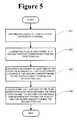
- FIG. 5is a flow chart illustrating a method for determining a flow rate of a fluid according to certain embodiments.
- FIG. 6is a block diagram illustrating a computer system upon which certain embodiments may be implemented.
- thermal “time of flight” methodinvolves measuring the motion of a small heated volume of fluid down a flow path to determine a flow rate of the fluid.
- An aliquot of fluidis heated at a first position in the flow path, and at a predetermined second position downstream from the first, the passage of the heated aliquot of fluid is detected by a sensor.
- the sensormay measure different parameters of the fluid in the flow path to determine when the heated portion passes the sensor. For example, the sensor may shine a light through a fluid-delivery channel through which the fluid flows to determine when the heated aliquot passes.
- a measured change in index of refraction at the sensorindicates the passage of the heated aliquot of fluid.
- less-than-transparent fluidse.g., translucent and opaque fluids such as lipids, packed cells, total parenteral nutrition (“TPN”), blood, breast milk, etc.
- an optical flow sensorprovides accurate measurement of flow rate for any fluid, whether opaque or transparent, at a relatively low cost.
- FIG. 1A block diagram illustrating an exemplary optical flow sensor according to certain embodiments is illustrated in FIG. 1 .
- Optical flow sensor 100includes a heater 101 configured to heat an aliquot 102 of fluid 103 in a fluid-delivery channel 104 adjacent to heater 101 .
- heater 101may be a laser.
- heater 101may be any one of a number of other heating devices, including electrical heaters, resistors, etc.
- Optical flow sensor 100further includes a sensor 105 disposed adjacent to fluid-delivery channel 104 downstream a predetermined distance d from heater 101 .
- Sensor 105is configured to illuminate fluid 103 in fluid-delivery channel 104 .
- sensor 105may illuminate fluid 103 with an LED 106 .
- sensor 105may illuminate fluid 103 with any one of a number of other light sources, including, for example, a laser, an incandescent filament, a fluorescent bulb, etc.
- sensor 105may illuminate fluid 103 with radiation of any wavelength, including visible light, infrared, ultraviolet, etc.
- Sensor 105is further configured to collect reflected light from the illuminated fluid 103 , and to determine when heated aliquot 102 passes sensor 105 based upon an amount of the reflected light.
- sensor 105may include a photodetector 107 optically coupled to fluid-delivery channel 104 with a polished fiber, a lens, a prism, or the like.
- sensor 105includes a first highly polished fiber 108 that optically couples LED 106 to fluid-delivery channel 104 , and a second highly polished fiber 109 that optically couples photodetector 107 to fluid-delivery channel 104 .
- photodetector 107may be an optical photodetector.
- photodetector 107may be any one of a number of other light or radiation sensors, including a photoresistor, a photovoltaic cell, a photodiode, etc.
- both LED 106 and photodetector 107are disposed on the same side of fluid-delivery channel 104 .
- This arrangementallows optical flow sensor 100 to determine the flow rate of fluids not previously suitable for time-of-flight rate sensing, such as opaque fluids, non-homogenous fluids, non-Newtonian fluids and the like.
- FIG. 2is a block diagram illustrating an optical flow sensor 200 according to another exemplary embodiment.
- Optical flow sensor 200includes a heater 201 configured to heat an aliquot 202 of fluid 203 in a fluid-delivery channel 204 adjacent to heater 201 .
- Optical flow sensor 200further includes a sensor 205 disposed adjacent to fluid-delivery channel 204 downstream a predetermined distance d from heater 201 .
- Sensor 205is configured to illuminate fluid 203 in fluid-delivery channel 204 with an LED 206 optically coupled to fluid-delivery channel 204 with a lens 208 .
- Sensor 205is further configured to collect reflected light from the illuminated fluid 203 , and to determine when heated aliquot 202 passes sensor 205 based upon an amount of the reflected light.
- sensor 205includes a photodetector 207 optically coupled to fluid-delivery channel 204 with a lens 209 .
- both LED 206 and photodetector 207are disposed on the same side of fluid-delivery channel 204 .
- This arrangementallows optical flow sensor 200 to determine the flow rate of fluids not previously suitable for time-of-flight rate sensing, such as opaque fluids, non-homogenous fluids, non-Newtonian fluids and the like.
- FIG. 3illustrates a medicinal fluid administering system in accordance with one exemplary embodiment.
- Medicinal fluid administering system 300includes a fluid delivery system for administering a fluid to a patient and optical flow sensor 200 , which is configured to measure a rate at which the fluid is administered to the patient.
- the fluid delivery systemincludes a fluid reservoir 301 , from which fluid 313 is pumped by a pump 302 through a fluid delivery path 303 a to the optical flow sensor 310 and on (via delivery path 303 b ) to the patient.
- the optical flow sensor 310includes a heater 311 configured to heat an aliquot 312 of fluid 313 in a fluid-delivery channel 314 adjacent to heater 311 .
- Optical flow sensor 310further includes a sensor 315 disposed adjacent to fluid-delivery channel 314 downstream a predetermined distance d from heater 311 .
- Sensor 315is configured to illuminate fluid 313 in fluid-delivery channel 314 with an LED 316 optically coupled to fluid-delivery channel 314 with a lens.
- Sensor 315is further configured to collect reflected light from the illuminated fluid 313 , and to determine when heated aliquot 312 passes sensor 315 based upon an amount of the reflected light.
- sensor 315includes a photodetector 317 optically coupled to fluid-delivery channel 314 with a lens.
- FIG. 4illustrates a medicinal fluid administering system utilizing a closed-loop control system in accordance with one exemplary embodiment.
- Medicinal fluid administering system 400includes a fluid delivery system for administering a fluid to a patient and optical flow sensor 200 , which is configured to measure a rate at which the fluid is administered to the patient.
- the fluid delivery systemincludes a fluid reservoir 401 , from which fluid 413 is pumped by a pump 402 through a fluid delivery path 403 a to the optical flow sensor 410 and on (via delivery path 403 b ) to the patient.
- the optical flow sensor 410includes a heater 411 configured to heat an aliquot 412 of fluid 413 in a fluid-delivery channel 414 adjacent to heater 411 .
- Optical flow sensor 410further includes a sensor 415 disposed adjacent to fluid-delivery channel 414 downstream a predetermined distance d from heater 411 .
- Sensor 415is configured to illuminate fluid 413 in fluid-delivery channel 414 with an LED 416 optically coupled to fluid-delivery channel 414 with a lens.
- Sensor 415is further configured to collect reflected light from the illuminated fluid 413 , and to determine when heated aliquot 412 passes sensor 415 based upon an amount of the reflected light.
- sensor 415includes a photodetector 417 optically coupled to fluid-delivery channel 414 with a lens.
- System 400further includes a controller 418 configured to calculate a flow rate of fluid 413 based by dividing the time between heater 411 heating aliquot 412 and heated aliquot 412 being detected by sensor 415 .
- Controller 418may be further configured to adjust a pumping rate of pump 402 based upon a difference between the calculated flow rate and a desired flow rate (e.g., by reducing or increasing the pump speed).
- FIG. 5is a flow chart illustrating a method for determining a flow rate of a fluid in accordance with one embodiment of the present invention.
- the methodbegins in step 501 , in which an aliquot of fluid is heated at a first position of a fluid-delivery channel.
- fluid in the fluid-delivery channelis illuminated at a second position, downstream from the first position.
- the amount of light reflected from the illuminated fluidis measured in step 503 to determine a change in the amount corresponding to the heated aliquot passing the second position.
- the flow rate of the fluidis calculated based upon a distance between the first position and the second position, and upon a time between heating the aliquot and the heated aliquot passing the second position.
- FIG. 6is a block diagram that illustrates a computer system 600 upon which certain embodiments may be implemented.
- Computer system 600includes a bus 602 or other communication mechanism for communicating information, and a processor 604 coupled with bus 602 for processing information.
- Computer system 600also includes a memory 606 , such as a random access memory (“RAM”) or other dynamic storage device, coupled to bus 602 for storing information and instructions to be executed by processor 604 .
- Memory 606may also be used for storing temporary variables or other intermediate information during execution of instructions by processor 604 .
- Computer system 600further includes a data storage device 610 , such as a magnetic disk or optical disk, coupled to bus 602 for storing information and instructions.
- Computer system 600may be coupled via I/O module 608 to a display device (not illustrated), such as a cathode ray tube (“CRT”) or liquid crystal display (“LCD”) for displaying information to a computer user.
- a display devicesuch as a cathode ray tube (“CRT”) or liquid crystal display (“LCD”) for displaying information to a computer user.
- An input devicesuch as, for example, a keyboard or a mouse may also be coupled to computer system 600 via I/O module 608 for communicating information and command selections to processor 604 .
- determining a flow rate of a fluidis performed by a computer system 600 in response to processor 604 executing one or more sequences of one or more instructions contained in memory 606 .
- Such instructionsmay be read into memory 606 from another machine-readable medium, such as data storage device 610 .
- Execution of the sequences of instructions contained in main memory 606causes processor 604 to perform the process steps described herein.
- processors in a multi-processing arrangementmay also be employed to execute the sequences of instructions contained in memory 606 .
- hard-wired circuitrymay be used in place of or in combination with software instructions to implement various embodiments. Thus, embodiments are not limited to any specific combination of hardware circuitry and software.
- machine-readable mediumrefers to any medium that participates in providing instructions to processor 604 for execution. Such a medium may take many forms, including, but not limited to, non-volatile media, volatile media, and transmission media.
- Non-volatile mediainclude, for example, optical or magnetic disks, such as data storage device 610 .
- Volatile mediainclude dynamic memory, such as memory 606 .
- Transmission mediainclude coaxial cables, copper wire, and fiber optics, including the wires that comprise bus 602 . Transmission media can also take the form of acoustic or light waves, such as those generated during radio frequency and infrared data communications.
- Machine-readable mediainclude, for example, floppy disk, a flexible disk, hard disk, magnetic tape, any other magnetic medium, a CD-ROM, DVD, any other optical medium, punch cards, paper tape, any other physical medium with patterns of holes, a RAM, a PROM, an EPROM, a FLASH EPROM, any other memory chip or cartridge, a carrier wave, or any other medium from which a computer can read.
Landscapes
- Physics & Mathematics (AREA)
- Fluid Mechanics (AREA)
- Health & Medical Sciences (AREA)
- General Physics & Mathematics (AREA)
- Heart & Thoracic Surgery (AREA)
- Engineering & Computer Science (AREA)
- Anesthesiology (AREA)
- Biomedical Technology (AREA)
- Vascular Medicine (AREA)
- Hematology (AREA)
- Life Sciences & Earth Sciences (AREA)
- Animal Behavior & Ethology (AREA)
- General Health & Medical Sciences (AREA)
- Public Health (AREA)
- Veterinary Medicine (AREA)
- Infusion, Injection, And Reservoir Apparatuses (AREA)
Abstract
Description
Claims (7)
Priority Applications (2)
| Application Number | Priority Date | Filing Date | Title |
|---|---|---|---|
| US12/142,215US8034020B2 (en) | 2008-06-19 | 2008-06-19 | Optical flow sensor |
| US13/243,962US20120059318A1 (en) | 2008-06-19 | 2011-09-23 | Optical flow sensor |
Applications Claiming Priority (1)
| Application Number | Priority Date | Filing Date | Title |
|---|---|---|---|
| US12/142,215US8034020B2 (en) | 2008-06-19 | 2008-06-19 | Optical flow sensor |
Related Child Applications (1)
| Application Number | Title | Priority Date | Filing Date |
|---|---|---|---|
| US13/243,962DivisionUS20120059318A1 (en) | 2008-06-19 | 2011-09-23 | Optical flow sensor |
Publications (2)
| Publication Number | Publication Date |
|---|---|
| US20090318858A1 US20090318858A1 (en) | 2009-12-24 |
| US8034020B2true US8034020B2 (en) | 2011-10-11 |
Family
ID=41431962
Family Applications (2)
| Application Number | Title | Priority Date | Filing Date |
|---|---|---|---|
| US12/142,215Active2028-12-01US8034020B2 (en) | 2008-06-19 | 2008-06-19 | Optical flow sensor |
| US13/243,962AbandonedUS20120059318A1 (en) | 2008-06-19 | 2011-09-23 | Optical flow sensor |
Family Applications After (1)
| Application Number | Title | Priority Date | Filing Date |
|---|---|---|---|
| US13/243,962AbandonedUS20120059318A1 (en) | 2008-06-19 | 2011-09-23 | Optical flow sensor |
Country Status (1)
| Country | Link |
|---|---|
| US (2) | US8034020B2 (en) |
Cited By (29)
| Publication number | Priority date | Publication date | Assignee | Title |
|---|---|---|---|---|
| US20150246175A1 (en)* | 2014-02-28 | 2015-09-03 | Gary David Shubinsky | Infusion system and method which utilizes dual wavelength optical air-in-line detection |
| US20150354345A1 (en)* | 2014-06-06 | 2015-12-10 | Schlumberger Technology Corporation | Methods and Systems for Analyzing Flow |
| US20160228626A1 (en)* | 2015-02-06 | 2016-08-11 | Worth Innovations, Llc | Illumination Device for Breast Milk Pumping |
| US9839731B2 (en) | 2013-11-19 | 2017-12-12 | Patrick O'Malley | Light-based accessory apparatuses for breast pumps |
| US9995611B2 (en) | 2012-03-30 | 2018-06-12 | Icu Medical, Inc. | Air detection system and method for detecting air in a pump of an infusion system |
| US10022498B2 (en) | 2011-12-16 | 2018-07-17 | Icu Medical, Inc. | System for monitoring and delivering medication to a patient and method of using the same to minimize the risks associated with automated therapy |
| US10046112B2 (en) | 2013-05-24 | 2018-08-14 | Icu Medical, Inc. | Multi-sensor infusion system for detecting air or an occlusion in the infusion system |
| US10166328B2 (en) | 2013-05-29 | 2019-01-01 | Icu Medical, Inc. | Infusion system which utilizes one or more sensors and additional information to make an air determination regarding the infusion system |
| US10430761B2 (en) | 2011-08-19 | 2019-10-01 | Icu Medical, Inc. | Systems and methods for a graphical interface including a graphical representation of medical data |
| US10463788B2 (en) | 2012-07-31 | 2019-11-05 | Icu Medical, Inc. | Patient care system for critical medications |
| US10596316B2 (en) | 2013-05-29 | 2020-03-24 | Icu Medical, Inc. | Infusion system and method of use which prevents over-saturation of an analog-to-digital converter |
| US10635784B2 (en) | 2007-12-18 | 2020-04-28 | Icu Medical, Inc. | User interface improvements for medical devices |
| US10656894B2 (en) | 2017-12-27 | 2020-05-19 | Icu Medical, Inc. | Synchronized display of screen content on networked devices |
| US10850024B2 (en) | 2015-03-02 | 2020-12-01 | Icu Medical, Inc. | Infusion system, device, and method having advanced infusion features |
| US11135360B1 (en) | 2020-12-07 | 2021-10-05 | Icu Medical, Inc. | Concurrent infusion with common line auto flush |
| US11191897B2 (en) | 2019-03-04 | 2021-12-07 | Eitan Medical Ltd. | In cycle pressure measurement |
| US11246985B2 (en) | 2016-05-13 | 2022-02-15 | Icu Medical, Inc. | Infusion pump system and method with common line auto flush |
| US11278671B2 (en) | 2019-12-04 | 2022-03-22 | Icu Medical, Inc. | Infusion pump with safety sequence keypad |
| US11324888B2 (en) | 2016-06-10 | 2022-05-10 | Icu Medical, Inc. | Acoustic flow sensor for continuous medication flow measurements and feedback control of infusion |
| US11344673B2 (en) | 2014-05-29 | 2022-05-31 | Icu Medical, Inc. | Infusion system and pump with configurable closed loop delivery rate catch-up |
| US11344668B2 (en) | 2014-12-19 | 2022-05-31 | Icu Medical, Inc. | Infusion system with concurrent TPN/insulin infusion |
| US11883361B2 (en) | 2020-07-21 | 2024-01-30 | Icu Medical, Inc. | Fluid transfer devices and methods of use |
| US11890451B2 (en) | 2019-03-05 | 2024-02-06 | Eitan Medical Ltd. | Anti-free-flow valve |
| US12011567B2 (en) | 2018-02-11 | 2024-06-18 | Eitan Medical Ltd. | Flex-stroke infusion pump |
| US12186528B2 (en) | 2019-03-05 | 2025-01-07 | Eitan Medical Ltd. | Infusion pump cassette latch |
| US12214162B2 (en) | 2019-03-05 | 2025-02-04 | Eitan Medical Ltd. | Infusion pump with valve compensation |
| US12318576B2 (en) | 2019-03-05 | 2025-06-03 | Eitan Medical Ltd. | Infusion pump with toggling capability |
| US12350233B2 (en) | 2021-12-10 | 2025-07-08 | Icu Medical, Inc. | Medical fluid compounding systems with coordinated flow control |
| USD1091564S1 (en) | 2021-10-13 | 2025-09-02 | Icu Medical, Inc. | Display screen or portion thereof with graphical user interface for a medical device |
Families Citing this family (24)
| Publication number | Priority date | Publication date | Assignee | Title |
|---|---|---|---|---|
| US9151646B2 (en) | 2011-12-21 | 2015-10-06 | Deka Products Limited Partnership | System, method, and apparatus for monitoring, regulating, or controlling fluid flow |
| EP2665412B1 (en)* | 2011-01-17 | 2018-06-20 | Biosynergetics, Inc. | In-line flow meter |
| US10488848B2 (en) | 2011-12-21 | 2019-11-26 | Deka Products Limited Partnership | System, method, and apparatus for monitoring, regulating, or controlling fluid flow |
| US10228683B2 (en) | 2011-12-21 | 2019-03-12 | Deka Products Limited Partnership | System, method, and apparatus for monitoring, regulating, or controlling fluid flow |
| US9746093B2 (en) | 2011-12-21 | 2017-08-29 | Deka Products Limited Partnership | Flow meter and related system and apparatus |
| US9372486B2 (en) | 2011-12-21 | 2016-06-21 | Deka Products Limited Partnership | System, method, and apparatus for monitoring, regulating, or controlling fluid flow |
| US9746094B2 (en) | 2011-12-21 | 2017-08-29 | Deka Products Limited Partnership | Flow meter having a background pattern with first and second portions |
| US9724466B2 (en) | 2011-12-21 | 2017-08-08 | Deka Products Limited Partnership | Flow meter |
| US9435455B2 (en) | 2011-12-21 | 2016-09-06 | Deka Products Limited Partnership | System, method, and apparatus for monitoring, regulating, or controlling fluid flow |
| US9759343B2 (en) | 2012-12-21 | 2017-09-12 | Deka Products Limited Partnership | Flow meter using a dynamic background image |
| USD751690S1 (en) | 2013-11-06 | 2016-03-15 | Deka Products Limited Partnership | Apparatus to control fluid flow through a tube |
| USD745661S1 (en) | 2013-11-06 | 2015-12-15 | Deka Products Limited Partnership | Apparatus to control fluid flow through a tube |
| USD751689S1 (en) | 2013-11-06 | 2016-03-15 | Deka Products Limited Partnership | Apparatus to control fluid flow through a tube |
| USD752209S1 (en) | 2013-11-06 | 2016-03-22 | Deka Products Limited Partnership | Apparatus to control fluid flow through a tube |
| USD749206S1 (en) | 2013-11-06 | 2016-02-09 | Deka Products Limited Partnership | Apparatus to control fluid flow through a tube |
| US10796797B2 (en)* | 2015-01-30 | 2020-10-06 | Moxxly, LLC | Sensor network for breast pumping mothers |
| CN108697845B (en) | 2016-01-28 | 2021-09-17 | 德卡产品有限公司 | Apparatus for monitoring, regulating or controlling fluid flow |
| USD905848S1 (en) | 2016-01-28 | 2020-12-22 | Deka Products Limited Partnership | Apparatus to control fluid flow through a tube |
| RU168516U1 (en)* | 2016-02-26 | 2017-02-07 | Общество с ограниченной ответственностью "Вебзавод" | AUTONOMOUS OPTICAL LIQUID FLOW METER FOR MEDICAL DROPS |
| USD854145S1 (en) | 2016-05-25 | 2019-07-16 | Deka Products Limited Partnership | Apparatus to control fluid flow through a tube |
| RU2669485C1 (en)* | 2017-06-27 | 2018-10-11 | Общество с ограниченной ответственностью "Вебзавод" | Method for recording and counting the number of drops in an autonomous system for optical monitoring of intravenous infusion |
| WO2021021596A1 (en) | 2019-07-26 | 2021-02-04 | Deka Products Limited Partnership | Apparatus for monitoring, regulating, or controlling fluid flow |
| USD964563S1 (en) | 2019-07-26 | 2022-09-20 | Deka Products Limited Partnership | Medical flow clamp |
| WO2025117543A1 (en)* | 2023-11-28 | 2025-06-05 | Flextronics Ap, Llc | Fluidic analysis and control through image processing |
Citations (4)
| Publication number | Priority date | Publication date | Assignee | Title |
|---|---|---|---|---|
| US5533412A (en) | 1993-07-07 | 1996-07-09 | Ic Sensors, Inc. | Pulsed thermal flow sensor system |
| US6304328B1 (en)* | 1998-08-14 | 2001-10-16 | Research Foundation Of State University Of New York, The Office Of Technology Licensing, Suny | Non-contact temperature and concentration measurement on liquid surfaces |
| US6386050B1 (en)* | 1999-12-21 | 2002-05-14 | Agilent Technologies, Inc. | Non-invasive fluid flow sensing based on injected heat tracers and indirect temperature monitoring |
| US6582393B2 (en) | 2001-05-29 | 2003-06-24 | Therafuse, Inc. | Compensating drug delivery system |
Family Cites Families (1)
| Publication number | Priority date | Publication date | Assignee | Title |
|---|---|---|---|---|
| US8449500B2 (en)* | 2007-11-16 | 2013-05-28 | Baxter International Inc. | Flow pulsatility dampening devices for closed-loop controlled infusion systems |
- 2008
- 2008-06-19USUS12/142,215patent/US8034020B2/enactiveActive
- 2011
- 2011-09-23USUS13/243,962patent/US20120059318A1/ennot_activeAbandoned
Patent Citations (4)
| Publication number | Priority date | Publication date | Assignee | Title |
|---|---|---|---|---|
| US5533412A (en) | 1993-07-07 | 1996-07-09 | Ic Sensors, Inc. | Pulsed thermal flow sensor system |
| US6304328B1 (en)* | 1998-08-14 | 2001-10-16 | Research Foundation Of State University Of New York, The Office Of Technology Licensing, Suny | Non-contact temperature and concentration measurement on liquid surfaces |
| US6386050B1 (en)* | 1999-12-21 | 2002-05-14 | Agilent Technologies, Inc. | Non-invasive fluid flow sensing based on injected heat tracers and indirect temperature monitoring |
| US6582393B2 (en) | 2001-05-29 | 2003-06-24 | Therafuse, Inc. | Compensating drug delivery system |
Cited By (54)
| Publication number | Priority date | Publication date | Assignee | Title |
|---|---|---|---|---|
| US10635784B2 (en) | 2007-12-18 | 2020-04-28 | Icu Medical, Inc. | User interface improvements for medical devices |
| US11004035B2 (en) | 2011-08-19 | 2021-05-11 | Icu Medical, Inc. | Systems and methods for a graphical interface including a graphical representation of medical data |
| US12346879B2 (en) | 2011-08-19 | 2025-07-01 | Icu Medical, Inc. | Systems and methods for a graphical interface including a graphical representation of medical data |
| US11599854B2 (en) | 2011-08-19 | 2023-03-07 | Icu Medical, Inc. | Systems and methods for a graphical interface including a graphical representation of medical data |
| US10430761B2 (en) | 2011-08-19 | 2019-10-01 | Icu Medical, Inc. | Systems and methods for a graphical interface including a graphical representation of medical data |
| US11972395B2 (en) | 2011-08-19 | 2024-04-30 | Icu Medical, Inc. | Systems and methods for a graphical interface including a graphical representation of medical data |
| US11376361B2 (en) | 2011-12-16 | 2022-07-05 | Icu Medical, Inc. | System for monitoring and delivering medication to a patient and method of using the same to minimize the risks associated with automated therapy |
| US10022498B2 (en) | 2011-12-16 | 2018-07-17 | Icu Medical, Inc. | System for monitoring and delivering medication to a patient and method of using the same to minimize the risks associated with automated therapy |
| US11933650B2 (en) | 2012-03-30 | 2024-03-19 | Icu Medical, Inc. | Air detection system and method for detecting air in a pump of an infusion system |
| US10578474B2 (en) | 2012-03-30 | 2020-03-03 | Icu Medical, Inc. | Air detection system and method for detecting air in a pump of an infusion system |
| US9995611B2 (en) | 2012-03-30 | 2018-06-12 | Icu Medical, Inc. | Air detection system and method for detecting air in a pump of an infusion system |
| US10463788B2 (en) | 2012-07-31 | 2019-11-05 | Icu Medical, Inc. | Patient care system for critical medications |
| US11623042B2 (en) | 2012-07-31 | 2023-04-11 | Icu Medical, Inc. | Patient care system for critical medications |
| US12280239B2 (en) | 2012-07-31 | 2025-04-22 | Icu Medical, Inc. | Patient care system for critical medications |
| US10046112B2 (en) | 2013-05-24 | 2018-08-14 | Icu Medical, Inc. | Multi-sensor infusion system for detecting air or an occlusion in the infusion system |
| US12048831B2 (en) | 2013-05-24 | 2024-07-30 | Icu Medical, Inc. | Multi-sensor infusion system for detecting air or an occlusion in the infusion system |
| US10874793B2 (en) | 2013-05-24 | 2020-12-29 | Icu Medical, Inc. | Multi-sensor infusion system for detecting air or an occlusion in the infusion system |
| US11433177B2 (en) | 2013-05-29 | 2022-09-06 | Icu Medical, Inc. | Infusion system which utilizes one or more sensors and additional information to make an air determination regarding the infusion system |
| US10596316B2 (en) | 2013-05-29 | 2020-03-24 | Icu Medical, Inc. | Infusion system and method of use which prevents over-saturation of an analog-to-digital converter |
| US12059551B2 (en) | 2013-05-29 | 2024-08-13 | Icu Medical, Inc. | Infusion system and method of use which prevents over-saturation of an analog-to-digital converter |
| US10166328B2 (en) | 2013-05-29 | 2019-01-01 | Icu Medical, Inc. | Infusion system which utilizes one or more sensors and additional information to make an air determination regarding the infusion system |
| US11596737B2 (en) | 2013-05-29 | 2023-03-07 | Icu Medical, Inc. | Infusion system and method of use which prevents over-saturation of an analog-to-digital converter |
| US9839731B2 (en) | 2013-11-19 | 2017-12-12 | Patrick O'Malley | Light-based accessory apparatuses for breast pumps |
| US10342917B2 (en)* | 2014-02-28 | 2019-07-09 | Icu Medical, Inc. | Infusion system and method which utilizes dual wavelength optical air-in-line detection |
| US20150246175A1 (en)* | 2014-02-28 | 2015-09-03 | Gary David Shubinsky | Infusion system and method which utilizes dual wavelength optical air-in-line detection |
| US12083310B2 (en) | 2014-02-28 | 2024-09-10 | Icu Medical, Inc. | Infusion system and method which utilizes dual wavelength optical air-in-line detection |
| US11344673B2 (en) | 2014-05-29 | 2022-05-31 | Icu Medical, Inc. | Infusion system and pump with configurable closed loop delivery rate catch-up |
| US20150354345A1 (en)* | 2014-06-06 | 2015-12-10 | Schlumberger Technology Corporation | Methods and Systems for Analyzing Flow |
| US11344668B2 (en) | 2014-12-19 | 2022-05-31 | Icu Medical, Inc. | Infusion system with concurrent TPN/insulin infusion |
| US20160228626A1 (en)* | 2015-02-06 | 2016-08-11 | Worth Innovations, Llc | Illumination Device for Breast Milk Pumping |
| US12115337B2 (en) | 2015-03-02 | 2024-10-15 | Icu Medical, Inc. | Infusion system, device, and method having advanced infusion features |
| US10850024B2 (en) | 2015-03-02 | 2020-12-01 | Icu Medical, Inc. | Infusion system, device, and method having advanced infusion features |
| US12201811B2 (en) | 2016-05-13 | 2025-01-21 | Icu Medical, Inc. | Infusion pump system and method with common line auto flush |
| US11246985B2 (en) | 2016-05-13 | 2022-02-15 | Icu Medical, Inc. | Infusion pump system and method with common line auto flush |
| US11324888B2 (en) | 2016-06-10 | 2022-05-10 | Icu Medical, Inc. | Acoustic flow sensor for continuous medication flow measurements and feedback control of infusion |
| US12076531B2 (en) | 2016-06-10 | 2024-09-03 | Icu Medical, Inc. | Acoustic flow sensor for continuous medication flow measurements and feedback control of infusion |
| US11868161B2 (en) | 2017-12-27 | 2024-01-09 | Icu Medical, Inc. | Synchronized display of screen content on networked devices |
| US10656894B2 (en) | 2017-12-27 | 2020-05-19 | Icu Medical, Inc. | Synchronized display of screen content on networked devices |
| US11029911B2 (en) | 2017-12-27 | 2021-06-08 | Icu Medical, Inc. | Synchronized display of screen content on networked devices |
| US12333201B2 (en) | 2017-12-27 | 2025-06-17 | Icu Medical, Inc. | Synchronized display of screen content on networked devices |
| US12011567B2 (en) | 2018-02-11 | 2024-06-18 | Eitan Medical Ltd. | Flex-stroke infusion pump |
| US11191897B2 (en) | 2019-03-04 | 2021-12-07 | Eitan Medical Ltd. | In cycle pressure measurement |
| US12318576B2 (en) | 2019-03-05 | 2025-06-03 | Eitan Medical Ltd. | Infusion pump with toggling capability |
| US12186528B2 (en) | 2019-03-05 | 2025-01-07 | Eitan Medical Ltd. | Infusion pump cassette latch |
| US12214162B2 (en) | 2019-03-05 | 2025-02-04 | Eitan Medical Ltd. | Infusion pump with valve compensation |
| US11890451B2 (en) | 2019-03-05 | 2024-02-06 | Eitan Medical Ltd. | Anti-free-flow valve |
| US12268843B2 (en) | 2019-12-04 | 2025-04-08 | Icu Medical, Inc. | Infusion pump with safety sequence keypad |
| US11278671B2 (en) | 2019-12-04 | 2022-03-22 | Icu Medical, Inc. | Infusion pump with safety sequence keypad |
| US12310921B2 (en) | 2020-07-21 | 2025-05-27 | Icu Medical, Inc. | Fluid transfer devices and methods of use |
| US11883361B2 (en) | 2020-07-21 | 2024-01-30 | Icu Medical, Inc. | Fluid transfer devices and methods of use |
| US11135360B1 (en) | 2020-12-07 | 2021-10-05 | Icu Medical, Inc. | Concurrent infusion with common line auto flush |
| US12390586B2 (en) | 2020-12-07 | 2025-08-19 | Icu Medical, Inc. | Concurrent infusion with common line auto flush |
| USD1091564S1 (en) | 2021-10-13 | 2025-09-02 | Icu Medical, Inc. | Display screen or portion thereof with graphical user interface for a medical device |
| US12350233B2 (en) | 2021-12-10 | 2025-07-08 | Icu Medical, Inc. | Medical fluid compounding systems with coordinated flow control |
Also Published As
| Publication number | Publication date |
|---|---|
| US20120059318A1 (en) | 2012-03-08 |
| US20090318858A1 (en) | 2009-12-24 |
Similar Documents
| Publication | Publication Date | Title |
|---|---|---|
| US8034020B2 (en) | Optical flow sensor | |
| JP7349483B2 (en) | Liquid measurement system, device, and method optimized with temperature sensing | |
| US20250041509A1 (en) | Infusion system and method which utilizes dual wavelength optical air-in-line detection | |
| US6932796B2 (en) | Liquid metering system | |
| CN100411697C (en) | Encoding and detection of injector information | |
| US7847276B2 (en) | Impulse analysis for flow sensor-based fluid control system | |
| EP2689226B1 (en) | Sensor device for use in a medical fluid delivery system | |
| KR101943635B1 (en) | Thermal mass flow meter and Thermal mass flow measurement system | |
| EP2332598B1 (en) | Holographic occlusion detection system for infusion pumps | |
| CN109564124A (en) | Dosimetry system and method | |
| JP2018531366A (en) | Direct light differential measurement system | |
| JP2018531366A6 (en) | Direct light differential measurement system | |
| TW202415933A (en) | Multi-channel optical pressure sensor | |
| CN109789269A (en) | The medical supply with thermal type mass flow sensor for bubble detection | |
| CN103293157B (en) | Optical measuring device, optical measuring system and optical measuring method | |
| US20220236091A1 (en) | Thermal mass flowmeter | |
| US20250127411A1 (en) | Head-mounted apparatus and sensing method | |
| US20230414864A1 (en) | Methods and systems for optical-based fluid control in a fluid delivery system | |
| Oh et al. | Enhanced accuracy in gravity-based intravenous infusion using pulse oximeter drop counting and measured single-drop weights | |
| KR20250132517A (en) | Portable ventricular assist system with multi-channel optical pressure sensor |
Legal Events
| Date | Code | Title | Description |
|---|---|---|---|
| AS | Assignment | Owner name:CARDINAL HEALTH 303, INC., CALIFORNIA Free format text:ASSIGNMENT OF ASSIGNORS INTEREST;ASSIGNOR:DEWEY, PAUL;REEL/FRAME:021121/0031 Effective date:20080612 | |
| AS | Assignment | Owner name:CAREFUSION 303, INC.,CALIFORNIA Free format text:CHANGE OF NAME;ASSIGNOR:CARDINAL HEALTH 303, INC.;REEL/FRAME:023730/0406 Effective date:20090729 Owner name:CAREFUSION 303, INC., CALIFORNIA Free format text:CHANGE OF NAME;ASSIGNOR:CARDINAL HEALTH 303, INC.;REEL/FRAME:023730/0406 Effective date:20090729 | |
| AS | Assignment | Owner name:CAREFUSION 303, INC.,CALIFORNIA Free format text:CHANGE OF NAME;ASSIGNOR:CARDINAL HEALTH 303, INC.;REEL/FRAME:023800/0598 Effective date:20090801 Owner name:CAREFUSION 303, INC., CALIFORNIA Free format text:CHANGE OF NAME;ASSIGNOR:CARDINAL HEALTH 303, INC.;REEL/FRAME:023800/0598 Effective date:20090801 | |
| STCF | Information on status: patent grant | Free format text:PATENTED CASE | |
| FPAY | Fee payment | Year of fee payment:4 | |
| MAFP | Maintenance fee payment | Free format text:PAYMENT OF MAINTENANCE FEE, 8TH YEAR, LARGE ENTITY (ORIGINAL EVENT CODE: M1552); ENTITY STATUS OF PATENT OWNER: LARGE ENTITY Year of fee payment:8 | |
| MAFP | Maintenance fee payment | Free format text:PAYMENT OF MAINTENANCE FEE, 12TH YEAR, LARGE ENTITY (ORIGINAL EVENT CODE: M1553); ENTITY STATUS OF PATENT OWNER: LARGE ENTITY Year of fee payment:12 |