US8033983B2 - Medical implant - Google Patents
Medical implantDownload PDFInfo
- Publication number
- US8033983B2 US8033983B2US10/640,838US64083803AUS8033983B2US 8033983 B2US8033983 B2US 8033983B2US 64083803 AUS64083803 AUS 64083803AUS 8033983 B2US8033983 B2US 8033983B2
- Authority
- US
- United States
- Prior art keywords
- envelope
- assembly
- sleeve
- sling
- sleeves
- Prior art date
- Legal status (The legal status is an assumption and is not a legal conclusion. Google has not performed a legal analysis and makes no representation as to the accuracy of the status listed.)
- Expired - Fee Related, expires
Links
Images


Classifications
- A—HUMAN NECESSITIES
- A61—MEDICAL OR VETERINARY SCIENCE; HYGIENE
- A61B—DIAGNOSIS; SURGERY; IDENTIFICATION
- A61B17/00—Surgical instruments, devices or methods
- A61B17/00234—Surgical instruments, devices or methods for minimally invasive surgery
- A—HUMAN NECESSITIES
- A61—MEDICAL OR VETERINARY SCIENCE; HYGIENE
- A61B—DIAGNOSIS; SURGERY; IDENTIFICATION
- A61B17/00—Surgical instruments, devices or methods
- A61B17/04—Surgical instruments, devices or methods for suturing wounds; Holders or packages for needles or suture materials
- A61B17/06—Needles ; Sutures; Needle-suture combinations; Holders or packages for needles or suture materials
- A61B17/06066—Needles, e.g. needle tip configurations
- A61B17/06109—Big needles, either gripped by hand or connectable to a handle
- A—HUMAN NECESSITIES
- A61—MEDICAL OR VETERINARY SCIENCE; HYGIENE
- A61F—FILTERS IMPLANTABLE INTO BLOOD VESSELS; PROSTHESES; DEVICES PROVIDING PATENCY TO, OR PREVENTING COLLAPSING OF, TUBULAR STRUCTURES OF THE BODY, e.g. STENTS; ORTHOPAEDIC, NURSING OR CONTRACEPTIVE DEVICES; FOMENTATION; TREATMENT OR PROTECTION OF EYES OR EARS; BANDAGES, DRESSINGS OR ABSORBENT PADS; FIRST-AID KITS
- A61F2/00—Filters implantable into blood vessels; Prostheses, i.e. artificial substitutes or replacements for parts of the body; Appliances for connecting them with the body; Devices providing patency to, or preventing collapsing of, tubular structures of the body, e.g. stents
- A61F2/0004—Closure means for urethra or rectum, i.e. anti-incontinence devices or support slings against pelvic prolapse
- A61F2/0031—Closure means for urethra or rectum, i.e. anti-incontinence devices or support slings against pelvic prolapse for constricting the lumen; Support slings for the urethra
- A61F2/0036—Closure means for urethra or rectum, i.e. anti-incontinence devices or support slings against pelvic prolapse for constricting the lumen; Support slings for the urethra implantable
- A61F2/0045—Support slings
- A—HUMAN NECESSITIES
- A61—MEDICAL OR VETERINARY SCIENCE; HYGIENE
- A61F—FILTERS IMPLANTABLE INTO BLOOD VESSELS; PROSTHESES; DEVICES PROVIDING PATENCY TO, OR PREVENTING COLLAPSING OF, TUBULAR STRUCTURES OF THE BODY, e.g. STENTS; ORTHOPAEDIC, NURSING OR CONTRACEPTIVE DEVICES; FOMENTATION; TREATMENT OR PROTECTION OF EYES OR EARS; BANDAGES, DRESSINGS OR ABSORBENT PADS; FIRST-AID KITS
- A61F2/00—Filters implantable into blood vessels; Prostheses, i.e. artificial substitutes or replacements for parts of the body; Appliances for connecting them with the body; Devices providing patency to, or preventing collapsing of, tubular structures of the body, e.g. stents
- A61F2/0063—Implantable repair or support meshes, e.g. hernia meshes
- A—HUMAN NECESSITIES
- A61—MEDICAL OR VETERINARY SCIENCE; HYGIENE
- A61B—DIAGNOSIS; SURGERY; IDENTIFICATION
- A61B17/00—Surgical instruments, devices or methods
- A61B17/34—Trocars; Puncturing needles
- A61B17/3468—Trocars; Puncturing needles for implanting or removing devices, e.g. prostheses, implants, seeds, wires
- A—HUMAN NECESSITIES
- A61—MEDICAL OR VETERINARY SCIENCE; HYGIENE
- A61B—DIAGNOSIS; SURGERY; IDENTIFICATION
- A61B17/00—Surgical instruments, devices or methods
- A61B2017/00743—Type of operation; Specification of treatment sites
- A61B2017/00805—Treatment of female stress urinary incontinence
- A—HUMAN NECESSITIES
- A61—MEDICAL OR VETERINARY SCIENCE; HYGIENE
- A61B—DIAGNOSIS; SURGERY; IDENTIFICATION
- A61B17/00—Surgical instruments, devices or methods
- A61B17/04—Surgical instruments, devices or methods for suturing wounds; Holders or packages for needles or suture materials
- A61B17/06—Needles ; Sutures; Needle-suture combinations; Holders or packages for needles or suture materials
- A61B17/06004—Means for attaching suture to needle
- A61B2017/06019—Means for attaching suture to needle by means of a suture-receiving lateral eyelet machined in the needle
- A—HUMAN NECESSITIES
- A61—MEDICAL OR VETERINARY SCIENCE; HYGIENE
- A61B—DIAGNOSIS; SURGERY; IDENTIFICATION
- A61B17/00—Surgical instruments, devices or methods
- A61B17/04—Surgical instruments, devices or methods for suturing wounds; Holders or packages for needles or suture materials
- A61B17/06—Needles ; Sutures; Needle-suture combinations; Holders or packages for needles or suture materials
- A61B17/06004—Means for attaching suture to needle
- A61B2017/06042—Means for attaching suture to needle located close to needle tip
- A—HUMAN NECESSITIES
- A61—MEDICAL OR VETERINARY SCIENCE; HYGIENE
- A61B—DIAGNOSIS; SURGERY; IDENTIFICATION
- A61B17/00—Surgical instruments, devices or methods
- A61B17/04—Surgical instruments, devices or methods for suturing wounds; Holders or packages for needles or suture materials
- A61B17/06—Needles ; Sutures; Needle-suture combinations; Holders or packages for needles or suture materials
- A61B2017/06052—Needle-suture combinations in which a suture is extending inside a hollow tubular needle, e.g. over the entire length of the needle
- A—HUMAN NECESSITIES
- A61—MEDICAL OR VETERINARY SCIENCE; HYGIENE
- A61B—DIAGNOSIS; SURGERY; IDENTIFICATION
- A61B17/00—Surgical instruments, devices or methods
- A61B17/04—Surgical instruments, devices or methods for suturing wounds; Holders or packages for needles or suture materials
- A61B17/06—Needles ; Sutures; Needle-suture combinations; Holders or packages for needles or suture materials
- A61B17/06066—Needles, e.g. needle tip configurations
- A61B2017/06076—Needles, e.g. needle tip configurations helically or spirally coiled
- A—HUMAN NECESSITIES
- A61—MEDICAL OR VETERINARY SCIENCE; HYGIENE
- A61B—DIAGNOSIS; SURGERY; IDENTIFICATION
- A61B17/00—Surgical instruments, devices or methods
- A61B17/04—Surgical instruments, devices or methods for suturing wounds; Holders or packages for needles or suture materials
- A61B17/06—Needles ; Sutures; Needle-suture combinations; Holders or packages for needles or suture materials
- A61B17/06166—Sutures
- A61B2017/06171—Sutures helically or spirally coiled
Definitions
- the inventionrelates generally to implanting a device such as a surgical sling at an anatomical site in the body of a mammal. More particularly, the invention relates to delivering and placing the surgical sling (entirely or partially within an envelope or a sheath) at an anatomical site in the body of a female patient or a male patient.
- surgical slingsmay be used to support and/or reinforce a damaged or weakened portion in the body of a patient.
- a sling used for such a purposegenerally is made sufficiently porous to allow for growth of tissue through the mesh after implantation.
- the healing tissuegrows through openings in, for example, an implanted synthetic mesh, thereby assimilating the tissue with the mesh and adding structural integrity to the tissue.
- Surgical slingsmay be produced with yarns including monofilament and multifilament yarns. Multifilament yarns have small void areas or interstitial spaces between the yarn filaments.
- the yarns in the surgical slingmay be made of materials such as polypropylene and polyesters.
- the crevices and voids of a surgical slingmay harbor bacteria or other pathogens that contaminate the surgical sling during implantation.
- the bacteria or other pathogens harbored in the slingare introduced to the anatomical site where the sling is implanted.
- the anatomical site being repairedis poorly accessible to antimicrobial drugs applied intraoperatively to combat bacteria or other pathogens that may be picked up and introduced to the anatomical site during the surgery to implant the mesh.
- the inventionrelates to an implant, such as a surgical sling or mesh, for implantation at an anatomical site in the body of a patient, such as at the mid-urethra.
- the implantcan be disposed within an envelope or a sheath for delivery to and placement at the anatomical site, and such a combination (of an implant and an envelope) is referred to herein as an implant assembly.
- Implants and implant assemblies according to the inventionare relatively inexpensive, provide effective therapy, and require minimal training before use. Implants and implant assemblies according to the invention can be used to treat female urinary incontinence, including stress incontinence, for example.
- the inventionalso relates generally to methods of making and using implants and implant assemblies.
- the inventionaddresses deficiencies in the prior art by providing an implant assembly that reduces or prevents contamination of the implant and contamination of the patient's tissue during delivery of the implant assembly to the anatomical site.
- An operatorcan adjust and position the implant assembly at the anatomical site in the patient's body and maintain the correct position of the implant at the anatomical site during and after withdrawal of an envelope, which at least partially encloses the implant.
- the implant or implant assemblycan be easily associated with a delivery device.
- the delivery devicecan be used to position the implant assembly (such as a sling in an envelope) at the patient's urethra.
- Transvaginal, transabdominal (e.g., percutaneous), supra-pubic, pre-pubic, or transobturator approachescan be used to install and position the implants and the implant assemblies.
- exemplary delivery devices and methodologies that may be employed in combination with the implant assemblies of the inventioncan be found in U.S. patent application Ser. Nos. 10/093,498, 10/093,398, 10/093,450, 10/093,371, 10/094,352, and 10/093,424 filed in the United States Patent Office on Mar. 7, 2002, U.S. provisional patent application Ser. No. 60/418,827 filed in the United States Patent Office Oct. 15, 2002, U.S. provisional patent application Ser. No. 60/418,642 filed in the United States Patent Office Oct. 15, 2002, and U.S. provisional patent application Ser. No. 60/434,167 filed in the United States Patent Office Dec. 17, 2002, the disclosures of which are incorporated herein by reference.
- the inventionprovides an assembly for delivering an implant to an anatomical location in a body.
- the assemblyincludes an envelope having two sleeves.
- the two sleeves of the envelopeenclose the implant, such as a sling for the treatment of female urinary incontinence.
- the assemblyfurther includes a scaffold.
- the scaffoldis sized and shaped to be enclosed within a lumen of the envelope.
- the scaffoldis configured to couple the first sleeve and the second sleeve together.
- each of the sleeves of the envelopeis about the same length.
- the scaffoldincludes a fold to form a hinge between the first and second sleeves.
- the scaffoldmay be manufactured, for example, from rigid or flexible materials.
- At least one sleeve of the envelopeincludes a tongue, which overlaps at least a portion of the implant enclosed within the envelope.
- the tongue of the first sleeveis positioned within the lumen of the second sleeve.
- the tongueis an integral part of at least one sleeve.
- the assemblyincludes a tab joined to the envelope.
- the tabmay be a positioning member for positioning the implant in the body of the patient.
- the envelopeincludes a first sleeve section and a second sleeve section which interoperate to enclose at least a portion of the implant.
- a tab on the end of the first sleeve sectionis passed through the first sleeve section to a first end of the envelope.
- a tab access for accessing the tabis located at the first end of the envelope. The tab is accessible through the tab access to position the implant in the patient's body.
- a tab on the end of the second sleeve sectionis passed through the second sleeve section to a second end of the envelope and the tab is accessible through a tab access located at the second end of the envelope.
- the tab accessis a linear cut through at least one sleeve from the outside of the sleeve, into the lumen of the sleeve.
- the tab accessis a perforation or a series of perforations through the sleeve.
- the assemblyincludes an envelope with one or more sleeves having a first side and a second side.
- the envelopeencloses at least a portion of an implant, for example, a sling having a length and a width.
- the first side of the envelopeincludes at least one discontinuity that exposes the width along a first portion of the sling.
- the discontinuityis a gap disposed between the first and second portions of the first side of the envelope.
- the mid-length portion of the slingis devoid of covering (e.g., not enclosed) by the envelope. This mid-length portion of the sling may be de-tanged.
- the first side of the envelopehas a first slit-shaped aperture and a second slit-shaped aperture.
- the first and second slit-shaped aperturesmay be intermediately located along the length of the sling.
- the sling that is at least partially enclosed by the envelopethreads out of the envelope through the first slit-shaped aperture and threads back into the envelope through the second slit-shaped aperture, which creates a mid-length envelopeless sling loop that is external to the envelope.
- the mid-length envelopeless sling loopmay be de-tanged and is devoid of covering, e.g., external to the envelope.
- Additional embodiments of the assembly according to the inventioninclude at least one loading member included on an end of an envelope.
- the loading memberfacilitates interoperability of the envelope with a delivery device.
- the loading membermay be bonded to the implant, the envelope, the scaffold, or some combination.
- the loading membermay be, for example, a guide member, a guide tube, or some other type of male or female structure (such as a hook, loop, etc.) disposed at an end of the envelope for mating with a complementary structure on the delivery device.
- At least one of the sleeves of the envelopemay be manufactured from a composite of two or more materials. In one embodiment, the two sleeves of the invention are joined by a hinge.
- the envelope of the delivery devicemay include a visual indication mark, for example, a spacer, a clamp, a tinted area or other indication mark that provides a visual indication of the placement of the sling delivery device, i.e., the envelope and/or implant.
- the visual indicationmay be employed to inform the operator about the orientation of, for example, the sling.
- an assemblyin another aspect, includes an envelope having at least two sleeves that enclose at least a portion of the implant.
- the assemblyincludes a scaffold that is sized and shaped to fit within the lumen of the envelope.
- at least one of the sleeveshas a tongue portion that overlaps the implant.
- the assemblyincludes an envelope having at least one tab passed through a sleeve section to an end of the envelope and at least one tab access for accessing the tab that is located at an end of the envelope.
- the implant assemblyis positioned at the anatomical site in the patient's body.
- the envelopeis withdrawn from the patient's body.
- the envelopemay be withdrawn from the patient's body by pulling the tabs and pulling the hinge and the remaining portions of the envelope from the body of the patient.
- the implant assemblyis positioned at the mid urethra and a tab on a first sleeve section of an envelope is pulled through the tab access on an end of the envelope. The pulled tab tears a portion of the envelope away from the implant and a hinge section is pulled intravaginally to withdraw the envelope from a patient's body.
- the envelopemay also be withdrawn by cutting the tab accesses, separating the envelope into two sides along the cut tab access, accessing the internal tabs, pulling the internal tabs, and pulling the hinge and remaining portions of the envelope intravaginally from the body of the patient via the vagina.
- the envelopemay be withdrawn by cutting the hinge section and separating the first sleeve from the second sleeve.
- the envelopemay be withdrawn by cutting the scaffold and separating the first sleeve from the second sleeve.
- the envelopemay be withdrawn by cutting and separating the external tabs or the loading members, separating the first sleeve from the second sleeve and scaffold, separating the second sleeve from the scaffold, then pulling the scaffold from the body of the patient.
- the implantAfter withdrawal of the envelope, the implant remains where it was positioned at the anatomical site, for example, at the mid-urethra of the patient to treat female urinary incontinence.
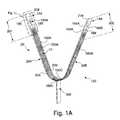
- FIG. 1Aillustrates one embodiment of an assembly for delivering an implant to a body.
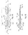
- FIG. 1Billustrates an embodiment of one of the sleeves illustrated in FIG. 1A .
- FIG. 1Cillustrates a cross section at 1 C- 1 C of the embodiment of the sleeve illustrated in FIG. 1B .
- FIG. 1Dillustrates an embodiment of one of the sleeves illustrated in FIG. 1A .
- FIG. 1Eillustrates a cross section at 1 E- 1 E of the embodiment of the sleeve illustrated in FIG. 1D .
- FIG. 1Fillustrates another embodiment of one of the sleeves illustrated in FIG. 1A .
- FIG. 1Gillustrates a cross section at 1 G- 1 G of the embodiment of the sleeve illustrated in FIG. 1F .
- FIG. 1Hillustrates one embodiment of a method for making the assembly for delivering an implant to a body illustrated in FIG. 1A .
- FIG. 1Iillustrates a top view of one embodiment of an assembly for delivering an implant to a body illustrated in FIG. 1A .
- FIG. 1Jillustrates one embodiment of a placement fork according to the invention.
- FIG. 1Killustrates a cross section at 1 K- 1 K of an embodiment of the assembly for delivering an implant to a body illustrated in FIG. 1I .
- FIG. 1Lillustrates an embodiment of a portion of the assembly for delivering an implant to a body illustrated in FIG. 1A .
- FIG. 1Millustrates another embodiment of the assembly for delivering an implant to a body illustrated in FIG. 1A .
- FIG. 2Aillustrates another embodiment of an assembly for delivering an implant to a body.
- FIG. 2Billustrates another embodiment of a portion of the assembly for delivering an implant to a body illustrated in FIG. 2A .
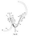
- FIG. 2Cillustrates another embodiment of an assembly for delivering an implant to a body illustrated in FIG. 2A .
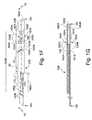
- FIG. 3Aillustrates one embodiment of an assembly for delivering an implant to a body.
- FIGS. 3B-3Gillustrate one embodiment of a method of making an assembly for delivering an implant to a body illustrated in FIG. 3A .
- FIG. 3Hillustrates a top view of one embodiment of the assembly for delivering an implant to a body illustrated in FIG. 3A .
- FIG. 3Iillustrates a cross-section at 3 I- 3 I of one embodiment of the assembly for delivering an implant to a body illustrated in FIG. 3H .
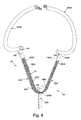
- FIG. 4illustrates another embodiment of an assembly for delivering an implant to a body.
- FIG. 5Aillustrates one embodiment of an assembly for delivering an implant to a body.
- FIG. 5Billustrates a top view of one embodiment of a scaffold for use in the assembly illustrated in FIG. 5A for delivering an implant to a body.
- FIG. 5Cillustrates a side view of the scaffold illustrated in FIG. 5B .
- FIG. 5Dillustrates another embodiment of the scaffold for use in the assembly illustrated in FIG. 5A .
- FIG. 5Eillustrates another embodiment of one of the sleeves illustrated in FIG. 5A .
- FIG. 5Fillustrates another one of the sleeves for use in the assembly illustrated in FIG. 5A for delivering an implant to a body.
- FIG. 5Gillustrates one embodiment of a method of making the assembly for delivering an implant to a body illustrated in FIG. 5A .
- FIG. 5Hillustrates a top view of one embodiment of the assembly for delivering an implant to a body illustrated in FIG. 5A .
- FIG. 5Iillustrates a cross-section at 5 I- 5 I of one embodiment of the assembly for delivering an implant to a body illustrated in FIG. 5H .
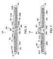
- FIG. 6illustrates a fragmented plan view of another embodiment of an assembly for delivering an implant to a body.
- FIG. 7illustrates a fragmented plan view of another embodiment of an assembly for delivering an implant to a body.
- the invention described hereinis an assembly for implanting an implant into the body of a patient.
- the assembly 120includes an envelope 20 enclosing an implant for example a sling 10 .
- an implantfor example, a surgical sling 10 formed from a mesh or other suitable material
- the implantis a surgical mesh.
- the surgical sling 10may be fabricated from one or more yarns and the yarns may be made from one or more materials. Materials that may be employed include polypropylene, polyesters, polyolefins, polytetrafluoroethylene, polyethylene, polyurethanes, nylons, and co-polymers, without limitation such as those described in U.S. Pat. No. 6,042,592, the entirety of which is incorporated by reference herein.
- the sling 10may also be a hybrid of synthetic materials and tissues.
- the sling 10may also be made from absorbable materials, such as, polyglycolic acid, polylactic acid and other suitable absorbable materials.
- Exemplary slings 10that may be employed with the invention are described in, for example, U.S. patent application Ser. No. 09/916,983 filed Jul. 27, 2001, provisional patent application Ser. No. 60/388,109 filed Jun. 12, 2002, U.S. patent application Ser. No. 10/460,112 filed Jun. 12, 2003, U.S. patent application Ser. No. 10/092,872 filed Mar. 7, 2002, provisional patent application Ser. No. 60/449,465 filed Feb. 24, 2003, and provisional patent application Ser. No. 60/465,722 filed Apr. 25, 2003 the entirety of all of which are incorporated by reference herein.
- Other exemplary slings 10that may be employed with the invention are described in the U.S. patent application Ser. No.
- the assembly 120 of the inventionwhich includes the envelope 20 and the sling 10 , may further include one or more spacers (not shown).
- spacersthat may be employed with the invention are described, for example, in provisional patent application Ser. No. 60/434,167 filed Dec. 17, 2002, provisional patent application Ser. No. 60/449,465 filed Feb. 24, 2003 and in the U.S. patent application Ser. No. 10/641,376, filed Aug. 14, 2003, entitled “Spacer for Sling Delivery System” by Chu et al. filed on even date herewith, the entirety of all of which are incorporated herein by reference.
- Each of the one or more yarns used to make the sling 10may include a plurality of filaments. Alternatively, a monofilament yarn may be employed.
- the sling 10is formed from a mesh and the mesh may be a polypropylene monofilament tricot mesh for use in surgical applications.
- each yarnmay have void areas between yarn filaments. The process used to fabricate the mesh may create crevices in the mesh. Multifilament yarns have multiple voids or interstitial spaces between the yarn filaments.
- Meshaccording to the invention, may be produced according to a variety of fabrication processes known to the skilled artisan including, but not limited to, knitting, weaving, or braiding.
- the surgical meshis enclosed within the envelope 20 that entirely or partially surrounds the surgical mesh.
- the envelope 20 surrounding the meshreduces the likelihood that the mesh will become contaminated with foreign matter, such as bacteria, during mesh placement at an anatomical site in the body of the patient.
- the illustrative envelopes 20may be of varying construction, for example, the envelope 20 may be used to assist in handling the sling 10 and/or to assist in adjusting the sling 10 during surgical placement. The envelope 20 also aids in preventing the sling 10 from stretching or becoming misshapen due to handling prior to placement at the anatomical site.
- the envelope 20may be likened to a pouch or a sleeve that partially or entirely surrounds the sling 10 .
- the thickness of the material used to make the envelope 20may range from about 0.0001 inch to about 0.01 inch, preferably being about 0.0003 inch thick.
- the envelope 20defines a lumen 185 through which at least a portion of the sling 10 can pass.
- the material used to make the envelope 20may be selected from the group including polypropylene, polyethylene, polyester, polytetrafluoroethylene (e.g., TEFLON®), TYVEK®, MYLAR®, and co-polymers, thereof.
- the material used to make the envelope 20is an absorbent material, such as, for example, a sponge-like material.
- the envelope 20may be pre-soaked in a solution containing a drug such as an antibiotic prior to surgical implantation of the implant 10 in a patient's body.
- sling 10is made of a non-wettable material such as a polypropylene, polyethylene, polyester, polytetrafluoroethylene, TYVEK available from DuPont, Pa., MYLAR available from DuPont, Pa., or co-polymers thereof.
- Polytetrafluoroethylenewhich is suitable for use in accordance with the present invention, is available from DuPont (Wilmington, Del., under the trade designation TEFLON).
- Such non-wettable materialsdo not take up any liquids, for example, therapeutic agents in solution.
- the sling 10may be treated with a substance that is wettable such as, for example, a wettable coating composition.
- the wettable coating compositionmay be a synthetic coating (e.g., polyvinylpyrrlidone or PVP), a natural coating (e.g., collagen) or a physically absorbent material (e.g., sponge comprising cellulose or open celled polyurethane).
- the wettable coating compositionmay be hydrophilic. Suitable hydrophilic coatings may be water soluble and include, for example, such coatings available under the trade designations Hydroplus and Hydropass.
- a hydrophobic coatingmay be employed on one or more surfaces of the sling 10 . Suitable hydrophobic coatings that may be employed in accordance with the invention include but are not limited to polytetrafluoroethylene, silicon, and Pyrelene.
- Therapeutic agentsmay also be employed with sling 10 .
- the hydrophilic coating and the therapeutic agentare mixed to form a single coating.
- the therapeutic agentsmay be compressed into the material of the sling 10 , rather than being applied as a coating.
- the therapeutic agentscan be, for example, hydrophilic or hydrophobic.
- Hydrophilic drugsthat may be employed in accordance with the invention include oxybutynin chloride, lidocaine, ketorolac, ketorolac tromethamine, which is available under the trade designation Toradol from Roche Pharmaceuticals (Nutley, N.J.) and hyoscyamine sulfate which is available under the trade designation CYTOSPAZ from Polymedica (Woburn, Mass.), for example.
- Suitable hydrophobic drugsinclude but are not limited to ibuprofen, ketoprofen, and diclofenac.
- the drugcan be mixed with the coating and applied with the coating. Where the bonding between the coatings and drugs is weak, the drug that is absorbed will readily release to be delivered to the sides it contacts. Alternatively, a stronger bonding affinity may provide a slower timed release of the drug.
- drugscomprising a complementary charge will bond to the coating when the coating and the drug are exposed to one another.
- the strength of any bondingwill impact how readily the drug is released from the sling 10 .
- the ionic bonding between the coating and the drugis weak, the drug will release more readily.
- covalent bonding between the side coating and the drugshould be avoided.
- the therapeutic agent for use in connection with the present inventioncan be any pharmaceutically acceptable therapeutic agent.
- Preferred therapeutic agentsinclude anti-inflammatory agents, analgesic agents, local anesthetic agents, antispasmodic agents, and combinations thereof.
- Anti-inflammatory agentsinclude steroidal and non-steroidal anti-inflammatory agents.
- non-steroidal anti-inflammatory drugsinclude aminoarylcarboxylic acid derivatives such as enfenamic acid, etofenamate, flufenamic acid, isonixin, meclofenamic acid, mefanamic acid, niflumic acid, talniflumate, terofenamate and tolfenamic acid; arylacetic acid derivatives such as acemetacin, alclofenac, amfenac, bufexamac, cinmetacin, clopirac, diclofenac sodium, etodolac, felbinac, fenclofenac, fenclorac, fenclozic acid, fentiazac, glucametacin, ibufenac, indomethacin, isofezolac, isoxepac, lonazolac, metiazinic acid, ox
- steroidal anti-inflammatory agentsinclude 21-acetoxyprefnenolone, aalclometasone, algestone, amicinonide, beclomethasone, betamethasone, budesonide, chloroprednisone, clobetasol, clobetasone, clocortolone, cloprednol, corticosterone, cortisone, cortivazol, deflazacort, desonide, desoximetasone, dexamethasone, diflorasone, diflucortolone, difluprednate, enoxolone, fluazacort, flucloronide, flumehtasone, flunisolide, fluocinolone acetonide, fluocinonide, fluocortin butyl, fluocortolone, fluorometholone, fluperolone acetate, fluprednidene a
- Analgesic agentsinclude narcotic and non-narcotic analgesics.
- Narcotic analgesic agentsinclude alfentanil, allylprodine, alphaprodine, anileridine, benzylmorphine, bezitramide, buprenorphine, butorphanol, clonitazene, codeine, codeine methyl bromide, codeine phosphate, codeine sulfate, desomorphine, dextromoramide, dezocine, diampromide, dihydrocodeine, dihydrocodeinone enol acetate, dihydromorphine, dimenoxadol, dimepheptanol, dimethylthiambutene, dioxaphetyl butyrate, dipipanone, eptazocine, ethoheptazine, ethylmethlythiambutene, ethylmorphine, etonitazene, f
- Non-narcotic analgesicsinclude aceclofenac, acetaminophen, acetaminosalol, acetanilide, acetylsalicylsalicylic acid, alclofenac, alminoprofen, aloxiprin, aluminum bis(acetylsalicylate), aminochlorthenoxazin, 2-amino-4-picoline, aminopropylon, aminopyrine, ammonium salicylate, amtolmetin guacil, antipyrine, antipyrine salicylate, antrafenine, apazone, aspirin, benorylate, benoxaprofen, benzpiperylon, benzydamine, bermoprofen, brofenac, p-bromoacetanilide, 5-bromosalicylic acid acetate, bucetin, bufexamac, bumadizon, butacetin, calcium acetylsalicylate, carbamazepine, carbi
- Local anesthetic agentsinclude amucaine, amolanone, amylocaine hydrochloride, benoxinate, benzocaine, betoxycaine, biphenamine, bupivacaine, butacaine, butaben, butanilicaine, butethamine, butoxycaine, carticaine, chloroprocaine hydrochloride, cocaethylene, cocaine, cyclomethycaine, dibucaine hydrochloride, dimethisoquin, dimethocaine, diperadon hydrochloride, dyclonine, ecgonidine, ecgonine, ethyl chloride, beta-eucaine, euprocin, fenalcomine, fomocaine, hexylcaine hydrochloride, hydroxytetracaine, isobutyl paminobenzoate, leucinocaine mesylate, levoxadrol, lidocaine, mepivacaine, meprylcaine, metabutoxycaine
- Antispasmodic agentsinclude alibendol, ambucetamide, aminopromazine, apoatropine, bevonium methyl sulfate, bietamiverine, butaverine, butropium bromide, n-butylscopolammonium bromide, caroverine, cimetropium bromide, cinnamedrine, clebopride, coniine hydrobromide, coniine hydrochloride, cyclonium iodide, difemerine, diisopromine, dioxaphetyl butyrate, diponium bromide, drofenine, emepronium bromide, ethaverine, feclemine, fenalamide, fenoverine, fenpiprane, fenpiverinium bromide, fentonium bromide, flavoxate, flopropione, gluconic acid, guaiactamine
- ketorolac and pharmaceutically acceptable salts thereofe.g., the tromethamine salt thereof, sold under the commercial name Toradol®
- 4-diethylamino-2-butynylphenylcyclohexylglycolate and pharmaceutically acceptable salts thereofe.g., 4-diethylamino-2-butynylphenylcyclohexylglycolate hydrochloride, also known as oxybutynin chloride, sold under the commercial name Ditropan®).
- the amount of the therapeutic agent present in the polymeric matrixis an amount effective to reduce the pain or discomfort associated with the medical device.
- the therapeutic agentis present in a polymeric matrix in a range from about 0.1% to about 30% by weight of the polymeric matrix (including 0.1%, 0.2%, 0.5%, 1%, 2%, 3%, 4%, 5%, 6%, 7%, 8%, 9%, 10%, 11%, 12%, 13%, 14%, 15%, 16%, 17%, 18%, 19%, 20%, 21%, 22%, 23%, 24%, 25%, 26%, 27%, 28%, 29%, 30% and ranges between any two of these points, for instance, 0.1-10%, 10-20% and 20-30%, etc.).
- oxybutynin chloride and ketorolac tromethamineare used a range of 2-20% is typical, more typically 5-15%.
- the operatorwithdraws the envelope 20 from the patient's body.
- the method of envelope 20 withdrawalmay vary according to the various envelope 20 constructions.
- the envelope 20may be withdrawn from the body without being torn.
- the operatortears or cuts the envelope 20 prior to withdrawal.
- the envelope 20 of FIGS. 1A , 1 H and 1 Kincludes a first sleeve 20 A, a second sleeve 20 B, tabs 188 , 198 , tab accesses 153 A, 153 B, 163 A and 163 B and the envelope hinge 200 .
- the tabs 188 and 198are internal tabs enclosed within the envelope 20 .
- the tab 188may be accessed from the inside of the envelope 20 and pulled outside the envelope 20 via the tab access 153 A.
- the envelope 20encloses the sling 10 .
- the tab accesses 153 A and 153 Bsimplify accessing the tabs 188 and 198 to enable withdrawal of envelope 20 .
- sleeve 20 Aincludes an inner surface 30 , an outer surface 40 , a proximal end 154 , a distal end 150 , a first lumen 185 A, a tab 188 coupled to a top section 150 A, and a bottom section 150 B.
- the sleeve 20 Afurther includes the tab access 153 A.
- the tab access 153 A and 153 Bmay be one or more cuts 220 A and 230 A, respectively, disposed through a surface or a tearable region 222 A of a sleeve 20 A of envelope 20 .
- the tearable region 222 Aincludes a material that is easily torn open. Such easily torn materials include, but are not limited to, a material with a molecular orientation such as a linear low density polyethylene or linear polytetrafluoroethylene.
- the envelope 20may be manufactured partially or entirely from these materials.
- the envelope 20may include sections including linear low density polyethylene along with sections including a series of perforations, cuts or apertures. Referring to FIGS. 1A , 1 D and 1 F, the envelope 20 includes a tearable region 222 A and 222 B with tabs 188 and 198 , respectively, that may be torn away.
- the tab access 153 Ais formed from one or more perforations, apertures or cuts 220 A that are disposed lengthwise along the length of the top surface 250 A of the first sleeve 20 A of envelope 20 .
- the tab access 153 Amay be placed transverse or at another angle relative to the length of a sleeve 20 A of envelope 20 .
- the tab access 153 Aincludes the series of cuts 220 A disposed on the top surface 250 A along the length of sleeve 20 A between one aperture, a first hole 151 A, and another aperture, a second hole 152 A.
- the tab access 153 Bincludes the series of cuts 230 A disposed on the bottom surface 250 B between one aperture, the first hole 151 B, and another aperture, the second hole 152 B.
- the diameter of the holes 151 A, 152 A, 151 B and 152 Bmay range between about 1/64 inches and about 1 ⁇ 4 inches, preferably being about 3/32 inches.
- the sleeve 20 A top surface 250 A and bottom surface 250 Bhave tab accesses 153 A and 153 B respectively.
- either the top surface 250 A or the bottom surface 250 B of sleeve 20 Ahas a tab access 153 A or 153 B.
- FIGS. 1A , 1 D and 1 Eillustrate another illustrative embodiment of the sleeve 20 A of assembly 120 .
- the tab 188is coupled to the top section 150 A and pulled into the first lumen 185 A of sleeve 20 A.
- the tab 188is positioned in the first lumen 185 A between the first hole 151 A and the second hole 152 A of tab access 153 A.
- sleeve 20 Ahas two first holes 151 A and 151 B, two second holes 152 A and 152 B, and the tab 188 . Referring now to FIG.
- the first holes 151 A and 151 Bmay be positioned between about 0.5 inch to about 2 inches, preferably about 1.5 inches from the proximal end 154 of sleeve 20 A. Each of the first holes 151 A and 151 B may be positioned at the same distance, or, alternatively, at different distances from the proximal end 154 .
- the second holes 152 A and 152 Bmay be positioned between about 0.05 inch to about 1 inch, preferably about 0.5 inch from the proximal end 154 of sleeve 20 A. Each of the second holes 152 A and 152 B may be positioned at the same distance, or, alternatively, at different distances from the proximal end 154 .
- the tab 188 that is coupled to top section 150 A and pulled into the first lumen 185 A of sleeve 20 Amay be positioned between about 0.25 inch to about 1.75 inch, preferably about 1 inch from the proximal end 154 of sleeve 20 A.
- FIG. 1Fillustrates a second sleeve 20 B of the envelope 20 shown in FIG. 1A .
- FIGS. 1F and 1Gillustrate the sleeve 20 B including an inner surface 30 , an outer surface 40 , a proximal end 160 , a distal end 164 , a second lumen 185 B, a tab 198 coupled to a top section 160 A, and a bottom section 160 B.
- the sleeve 20 Bfurther includes the tab accesses 163 A and 163 B.
- the tab access 163 Ais formed from one or more perforations, apertures or cuts 220 B disposed lengthwise along the length of the top surface 260 A of sleeve 20 B.
- the tab access 163 Bis formed from one or more perforations, apertures or cuts 230 B that are disposed lengthwise along the length of the bottom surface 260 B of sleeve 20 B.
- the tab accesses 163 A and 163 Bmay be placed transverse or at another angle relative to the length of sleeve 20 B of envelope 20 .
- the tab access 163 Aincludes a series of cuts 220 B disposed on the top surface 260 A lengthwise along the length of sleeve 20 B between one aperture, a first hole 161 A, and another aperture, a second hole 162 A.
- the tab access 163 Bincludes a series of cuts 230 B disposed on the bottom surface 260 B lengthwise along the length of sleeve 20 B between one aperture, a first hole 161 B, and another aperture, a second hole 162 B.
- the diameter of the holes 161 A, 162 A, 161 B and 162 Bmay range between about 1/64 inches and about 1 ⁇ 4 inches, preferably about 3/32 inches.
- either the top surface 260 A or the bottom surface 260 B of sleeve 20 Bhas a tab access 163 A or 163 B.
- the tab 198is coupled to the top section 160 A and is pulled into the second lumen 185 B of sleeve 20 B such that the tab 198 is positioned in the second lumen 185 B between the first holes 161 A and 161 B and the second holes 162 A and 162 B.
- FIGS. 1F and 1Gillustrate the sleeve 20 B having two first holes 161 A and 161 B, two second holes 162 A and 162 B and the tab 198 .
- the first holes 161 A and 161 Bmay be positioned between about 0.5 inch to about 2 inches, preferably about 1.5 inches from the distal end 164 of sleeve 20 B.
- Each of the first holes 161 A and 161 Bmay be positioned at the same distance, or, alternatively, at different distances from the distal end 164 of sleeve 20 B.
- the second holes 162 A and 162 Bmay be positioned between about 0.05 inch to about 1 inch, preferably about 0.5 inch from the distal end 164 of sleeve 20 B. Each of the second holes 162 A and 162 B may be positioned at the same distance, or, alternatively, at different distances from the distal end 164 .
- the tab 198 that is coupled to top section 160 A and pulled into the second lumen 185 B of sleeve 20 Bmay be positioned between the first holes 161 A and 161 B and the second holes 162 A and 162 B. In one embodiment, the tab 198 is positioned between about 0.25 inch to about 1.75 inch, preferably 1 inch from the distal end 164 of sleeve 20 B. Referring now to FIGS. 1A , 1 H, and 1 K, the tab accesses 153 A and 153 B are positioned at the first end 201 of the envelope 20 and the tab accesses 163 A and 163 B are positioned at the second end 202 of envelope 20
- the bottom section 150 B of the first sleeve 20 Ais placed at about a 90° angle relative to the length of the first sleeve 20 A.
- the bottom section 160 B of the second sleeve 20 Bis placed at about a 90° angle relative to the length of the second sleeve 20 B.
- the sleeves 20 A and 20 Bare aligned in proximity to one another such that the bottom sections 150 B and 160 B of sleeves 20 A and 20 B, respectively, face one another. Referring now to FIGS.
- the bottom sections 150 B and 160 Bact as hinge sections when the bottom sections 150 B and 160 B are joined to one another by adhesive, staples, heat bonding or other means known to the skilled person to form hinge 200 .
- a clip(not shown) may be employed to join the bottom sections 150 B and 160 B, forming hinge 200 .
- the sleeves 20 A and 20 Bform envelope 20 and the proximal end 154 of first sleeve 20 A is positioned on the opposite end from the distal end 164 of the second sleeve 20 B.
- the tab access 153 Ais located at a first end 201 of the envelope 20 and the tab access 163 A is located at the second end 202 of the envelope 20 .
- the tabs 188 and 198are located at the first end 201 and the second end 202 , respectively, of the envelope 20 .
- the tab 188is passed through the lumen 185 A of sleeve 20 A and is placed at the first end 201 of envelope 20 about the region of the tab access 153 A and the tab 198 is passed through the lumen 185 B of sleeve 20 B and is placed at the second end 202 of envelope 20 about the region of the tab access 163 A.
- the bottom sections 150 B and 160 B of sleeve 20 A and sleeve 20 Bform the hinge 200 of the envelope 20 .
- the envelope 20has a proximal end 154 and a distal end 164 , formed by the proximal end 154 and distal end 164 of sleeves 20 A and 20 B, respectively.
- the length of envelope 20from the proximal end 154 to the distal end 164 ranges between about 4.0 inches to about 28.0 inches, or between about 12.0 inches and about 24.0 inches, most preferably 20.0 inches.
- the top section 150 Ais not fully pulled into the sleeve 20 A, such that an overlap region 150 C of the top section 150 A remains on the outer surface 40 .
- the top section 160 A of sleeve 20 Bis not fully pulled into the sleeve 20 B, such that an overlap region 160 C of top section 160 A remains on the outer surface 40 .
- the overlap regions 150 C and 160 Crange between about 0.04 inches to about 1.2 inches, preferably about 0.3 inches.
- the overlap region 160 C of sleeve 20 B of envelope 20may lay on top of the overlap region 150 C of sleeve 20 A of envelope 20 .
- the overlap regions 150 C and 160 Cprotect the sling 10 enclosed within envelope 20 .
- the overlap regions 150 C and 160 C of the envelope 20prevents the sling 10 from stretching caused by, for example, a hemostat inadvertently applied to the sling 10 during surgery.
- the tab accesses, 153 A, 153 B, 163 A and 163 B or a portion of a tab accessfor example one or more hole 151 A, 152 A, 151 B and 152 B and/or one or more cut 220 A, 220 B, 230 A, and 230 B may be employed to sterilize envelope 20 and/or the sling 10 enclosed therein.
- ethylene oxide (ETO) gasis supplied to the lumen 185 of envelope 20 through a portion of or the entire tab access 153 A, 153 B, 163 A or 163 B.
- ETOis be supplied into the first hole 151 B of envelope 20 prior to operator placement inside the patient's body.
- a placement fork 170is employed to position an implant, such as a sling 10 , within envelope 20 .
- the placement fork 170has a fork handle 173 and fork prongs 171 .
- the placement fork 170has one or more fork prongs 171 .
- the placement fork 170has two or more fork prongs 171 .
- the fork prongs 171may be configured to have a pointed end 175 .
- the fork prongs 171may be configured with a flat end 175 .
- the fork prongs 171are configured with a rounded end 175 .
- a fork prong 171has a sharp end 175 or a dull end 175 .
- Placement forks 170may have multiple fork prongs 171 having different configurations.
- the placement fork 171is employed to place a sling 10 for treatment of female urinary incontinence in sleeves 20 A and 20 B of envelope 20 .
- sleeves 20 A and 20 Bmeasure 9.75 inches and the sling 10 measures 18 inches.
- the length of each fork prong 171may range from about 0.300 inch to about 0.400 inch, preferably about 0.350 inch long.
- the diameter of each fork prong 171may measure between about 0.028 inch to about 0.040 inch, preferably about 0.030 inch. In one embodiment, there are two fork prongs 171 on the placement fork 170 .
- each fork prong 171is spaced from about 0.090 inch to about 0.110 inch, preferably about 0.100 inch from the adjacent fork prong 171 on the placement fork 170 .
- the fork prongs 171have rounded ends 175 .
- the fork handle 173 lengthmay range from about 10 inches to about 12 inches, preferably about 11 inches long.
- the placement fork 170may be configured to fit within the lumen 185 of envelope 20 .
- the fork handle 173 and the fork prongs 171 of the placement fork 170may be fabricated from various materials, including medical grade stainless steel, for example 304 stainless tool steel, or medical grade plastic, for example nylon or TEFLON®.
- a material, such as a soft plasticmay be employed to cover the placement fork 170 handle 173 to provide ease of gripping and/or comfort to the operator using the placement fork 170 .
- the placement fork 170may be held by the fork handle 173 .
- the fork prongs 171may be used to position the sling 10 inside envelope 20 .
- the placement fork 170may have one or more fork prongs 171 . In one embodiment, the positioning fork 170 has two fork prongs 171 .
- the implanta sling 10
- the implantis pierced by the fork prongs 171 and positioned in the lumen 185 B of second sleeve 20 B of envelope 20 . Thereafter, the sling 10 is positioned in the lumen 185 A of first sleeve 20 A of envelope 20 .
- the prongs 171 of the placement fork 170are employed to position the sling 10 within the lumen 185 B of the second sleeve 20 B and within the lumen 185 A of the first sleeve 20 A, without piercing the sling 10 .
- the length of the handle 173 of placement fork 170may be selected according to the combined lengths of the sleeves 20 A and 20 B.
- the overlap regions 150 C and 160 Ccover the sling 10 enclosed within envelope 20 .
- the sling 10is placed within the envelope 20 after the bottom sections 150 B and 160 B of sleeves 20 A and 20 B are joined to form hinge 200 .
- the tabs 208 and 218are joined to the envelope 20 after the hinge 200 is formed.
- the tabs 208 and 218are external to the envelope 20 and they are positioning members for positioning the envelope 20 inside the body of the patient.
- the tabs 208 and 218are positioned at the proximal end 154 and the distal end 164 of envelope 20 , respectively.
- the implantfor example the sling 10
- the implantmay be manually inserted into lumen 185 of envelope 20 .
- the sling 10may be inserted into lumen 185 with the aid of a placement fork 170 described above with reference to FIG. 1J .
- the sling 10is manually placed within the first lumen 185 A of the first sleeve 20 A and/or placed with the aid of the placement fork 170 or a grasping device, such as, for example, forceps. Thereafter, sleeve 20 B is joined with the sleeve 20 A to form the envelope 20 , including the hinge 200 . The remaining portion of the sling 10 may be placed within the second lumen 185 B of sleeve 20 B prior to or after forming the hinge 200 .
- the sling 10is placed, via the tab accesses, 153 A, 153 B, 163 A, and 163 B, within the envelope 20 after the sleeves 20 A and 20 B are joined at hinge 200 .
- the sling 10is inserted into, for example, cut 230 B of tab access 163 B manually and/or with the aid of a grasping device or the placement fork 170 and the sling 10 is positioned within lumen 185 .
- the sling 10is placed within the envelope 20 via the tab accesses, 153 A, 153 B, 163 A, and/or 163 B after the sleeves 20 A and 20 B are joined at hinge 200 , and after tabs 208 and 218 are joined to the envelope 20 .
- the inventionincludes a method for positioning the sling 10 at an anatomical site in the body of a patient.
- the operatorpositions the assembly 120 of the envelope 20 enclosing sling 10 at the anatomical site, for example, the urethra 999 or bladderneck of a female patient.
- the tab 188 and the tab access 153 Aare located at the first end 201 of the envelope. The operator accesses the tab 188 by pulling tab 188 through cut 220 A of tab access 153 A.
- the top section 150 A of sleeve 20 Ais torn away from the envelope 20 in a single piece to expose the implant sling 10 .
- Tab 188 , the top section 150 A, the top of sleeve 20 A, and a portion of the proximal top section 154 Aare torn away from the envelope 20 and the implant sling 10 is exposed.
- the exposed portion of the sling 10is adjacent the urethra 999 .
- the operatorsimilarly accesses tab 198 by pulling tab 198 through cut 220 B of tab access 163 A.
- the tab 198 and the tab access 163 Aare located at the second end 202 of the envelope 20 .
- the operator intravaginallygrasps hinge 200 and simultaneously pulls tab 198 .
- the force exerted on tab 198 coupled to the top section 160 Atears the envelope 20 along the top surface 260 A of the sleeve 20 B away from the envelope 20 .
- the force exerted on tab 198 coupled to the top section 160 Atears these portions of sleeve 20 B away from the envelope 20 .
- tab 198the top section 160 A, the top of sleeve 20 B, and a portion of the distal top section 164 A are withdrawn from envelope 20 .
- the portion of the sling 10 previously enclosed by the envelope 20is thereby exposed.
- the hinge 200 and the remainder of envelope 20 including the tabs 208 and 218are withdrawn via the patient's vagina.
- the sling 10remains inside the body of the patient at the anatomical site where the operator positioned the sling 10 , for example, at the anatomical site of the urethra 999 .
- FIGS. 2A-2Cillustrate the envelope 20 , described in accordance with FIGS. 1A-1M , further including a first guide tube 350 A and a second guide tube 350 B.
- the assembly 120includes the envelope 20 including first sleeve 20 A, second sleeve 20 B, tabs 188 , 198 , tab accesses 153 A, 153 B, 163 A, and 163 B, the envelope hinge 200 , the envelope 20 enclosing all or part of sling 10 .
- a first guide tube 350 Ais coupled to the proximal end 154 of first sleeve 20 A and the second guide tube 350 B is coupled to the distal end 164 of the second sleeve 20 B of envelope 20 .
- the first guide tube 350 A, the proximal end 154 , and the tab access 153 A and the second guide tube 350 B, the distal end 164 , and the tab access 163 Aare positioned on opposite ends of the envelope 20 formed by sleeve 20 A and sleeve 20 B.
- the tab access 153 A and 153 Bare positioned at the first end 201 of the envelope 20 and the tab accesses 163 A and 163 B are positioned at the second end 202 of the envelope 20 .
- the guide tubes 350 A and 350 Bfacilitate interoperability of the assembly 120 with a delivery device.
- Other structures that facilitate interoperability of the assembly 120 with a delivery device to introduce the assembly 120 to the body of the patientmay be employed in accordance with the assembly 120 of the invention.
- Suitable configurations and structuresinclude, for example, loops, apertures, male and/or female connectors, guide tubes and the like.
- Such other structures that may be employedare described in more detail in the U.S. patent application Ser. Nos. 10/093,371, 10/093,398, 10/093,424, 10/093,450, 10/093,498, and 10/094,352 filed in the United States Patent Office on Mar. 7, 2002, which are based on and claim priority to provisional patent application Ser. No.
- the operatormay employ the assembly 120 of the invention to position the implant at an anatomical site in the body of a patient.
- the operatorwill employ the first and second guide tube 350 A and 350 B to position the envelope 20 enclosing sling 10 at an anatomical site in the body of a patient.
- Other structures as described and incorporated herein abovemay be used to position the envelope 20 enclosing sling 10 at an anatomical site in the body of a patient.
- the envelope 20may be positioned with the aid of a delivery device that may be employed to access the patient's urethra 999 according to supra-pubic, pre-pubic, transvaginal, or transobturator approaches.
- the operatorpositions the envelope 20 enclosing sling 10 , at the anatomical site, for example, the urethra 999 or bladderneck.
- the operatoraccesses the tab 188 by pulling tab 188 through cut 220 A of tab access 153 A.
- the operatorintravaginally grasps hinge 200 and simultaneously pulls the tab 188 in the direction indicated by arrow 189 .
- the force on tab 188 coupled to the top section 150 Atears the envelope 20 along the top portion of the first sleeve 20 A. Thereafter, the top section 150 A of sleeve 20 A is torn away from the envelope 20 in a single piece to expose the implant sling 10 .
- Tab 188the top section 150 A, the top surface 250 A of sleeve 20 A, and a portion of the proximal top section 154 A are torn away from the envelope 20 and the implant sling 10 is exposed.
- the exposed portion of the sling 10is adjacent the urethra 999 .
- tab 198similarly accesses tab 198 by pulling tab 198 through cut 220 B of tab access 163 A.
- the operatorintravaginally grasps hinge 200 and simultaneously pulls tab 198 .
- the force exerted on tab 198 coupled to the top section 160 Atears these portions of sleeve 20 B away from the envelope 20 .
- tab 198 , the top section 160 A, the top surface 260 A of sleeve 20 B, and a portion of the distal top section 164 Aare withdrawn from envelope 20 .
- the portion of the sling 10 previously enclosedis thereby exposed.
- the hinge 200 and the remainder of envelope 20 including the first guide tube 350 A and the guide tube 350 Bare withdrawn via the patient's vagina.
- the sling 10remains inside the body of the patient at the anatomical site where the operator positioned the sling 10 , for example, at the anatomical site of the urethra 999 .
- the tab accesses 153 A and 153 Binclude perforations (not shown) about the perimeter of the perpendicular axis 24 A of sleeve 20 A of envelope 20 .
- the operatorcan access the tab 188 by grasping and withdrawing, for example, the guide tube 350 A and the portion of the envelope 20 lying between the perforation and the envelope 20 proximal end 154 .
- the tab 188is thereby exposed and is accessible to the operator.
- the envelope 20 tab access 153 Ahas perforations about the perimeter of the perpendicular axis 24 A of envelope 20 and also has a nick (not shown) at one or more portions of the perforated perimeter that enables the tab access 153 A to be pulled or torn to expose the tab 188 enclosed within the envelope 20 .
- the tab access 153 A and 153 Bincludes shapes (not shown) cut out of one or more of the top surfaces 250 A, 260 A and bottom surfaces 250 B, 260 B of sleeves 20 A and 20 B, respectively.
- Suitable cut out shapesinclude, oval and triangle, and the triangular cut out shape may have, for example, rounded edges.
- the envelope 20 enclosing an sling 10is positioned inside the body of a patient.
- the tab access 153 Aincluding a cut 220 A disposed between the first hole 151 A and the second hole 152 A
- the tab access 153 Bincluding a cut 230 A disposed between the first hole 151 B and the second hole 152 B, are cut at position 437 A.
- the cut at position 437 Acuts through the second holes 152 A and 152 B.
- the guide tube 350 A and a portion of the envelope materialare withdrawn.
- the sides of envelope 20 sleeve 20 Aare pulled apart by opening and separating each of the cuts 220 A and 230 A.
- the sides of envelope 20separate until the point where the first holes 151 A and 151 B are located.
- the first holes 151 A and 151 Bmay provide, for example, relief to the cuts 220 A and 230 A.
- tab accesses 163 A, 163 B on sleeve 20 Bare cut at position 437 B and tab 198 is similarly accessed by separating the sides of the envelope 20 .
- the guide tube 350 B and a portion of the envelopeare withdrawn.
- the operatorcuts the envelope 20 at position 437 A, withdraws the first guide tube 350 A, and separates the envelope 20 to provide accesses to the tab 188 .
- the operatorintravaginally grasps hinge 200 and simultaneously pulls the tab 188 and the force on tab 188 coupled to the top section 150 A tears the envelope 20 along the top portion of the first sleeve 20 A.
- the top section 150 A of sleeve 20 Ais torn away from the envelope 20 in a single piece to expose the implant sling 10 .
- Tab 188the top section 150 A, the top surface 250 A of sleeve 20 A, and a portion of the proximal top section 154 A are torn away from the envelope 20 and the implant sling 10 is exposed.
- the exposed portion of the sling 10is adjacent the anatomical site
- the operatorcuts the envelope 20 at position 437 B, withdraws the second guide tube 350 B, and separates the envelope 20 to provide accesses to the tab 198 .
- the operatorgrasps hinge 200 and simultaneously pulls tab 198 .
- the force exerted on tab 198 coupled to the top section 160 Atears these portions of sleeve 20 B away from the envelope 20 .
- tab 198 , the top section 160 A, the top surface 260 A of sleeve 20 B, and a portion of the distal top section 164 Aare withdrawn from envelope 20 .
- the portion of the sling 10 previously enclosedis thereby exposed.
- the hinge 200 and the remainder of envelope 20are withdrawn via the vagina.
- This embodimentavoids guide tubes 350 A and 350 B being pulled back through the patient's body when the operator withdraws the remainder of the envelope.
- the sling 10remains inside the body of the patient at the anatomical site where the operator positioned the sling 10 .
- the tab access 153 A and 153 Bis a cut out shape, for example, an oval (not shown).
- the cut out ovalmay be cut over positions 437 A and 437 B.
- positions 437 A, 437 Bwithdrawing a portion of the envelope 20 and first guide tube 350 A and a portion of the envelope 20 and a second guide tube 350 B.
- the portion of the envelope 20 below positions 437 A and 437 Bmay be separated until the point at the bottom of the oval, providing access to the tabs 188 , 198 enclosed within the envelope 20 .
- the inventionincludes an assembly 120 for delivering the envelope 20 and an implant, for example, a sling 10 to an anatomical site in the body of a patient.
- the assembly 120includes the envelope 20 including two or more sleeves 20 A, 20 B, one or more tabs 208 , 218 and a tongue 155 .
- the tongue 155simplifies placement and/or withdrawal of the envelope 20 from inside the body of the patient and prevents damage to the sling 10 thereby maintaining the integrity of the sling 10 enclosed by the envelope 20 .
- the tongue 155is an extension of the top section 150 A of the sleeve 20 A.
- the tongue 155extends from one end of the sleeve 20 A.
- the tongue 155is separate, i.e., non-contiguous with the bottom section 150 B of the sleeve 20 A.
- tongue 155extends from the top section 150 A beyond the lumen 185 A of the sleeve 20 A.
- the tonguemay be flexible and it may be any flat shape, for example, rectangular or oval.
- the length of the tonguemeasures between about 0.2 inches and about 5 inches, preferably about 1 inch in length.
- the width of the tonguemeasures between about 0.1 inches and about 2.0 inches.
- the thickness of the tongue 155is at least as thick as the sleeve from which the tongue is made. In another embodiment, the tongue 155 is bonded at an end of sleeve 20 A, in such embodiments the tongue 155 thickness may be greater, less, or equal to the thickness of the sleeve 20 A to which the tongue 155 is bonded.
- the tongue 155may be bonded to sleeve 20 A by adhesives, sutures, or heat bonding as well as by other bonding means known to the skilled person.
- the tongueis made by cutting two angles into the first sleeve 20 A, as indicated by the arrow 176 and arrow 178 .
- the angles 176 and 178are cut in the range of from about 40° to about 170°, or about 80° to about 130°, preferably about 110°, from the longitudinal axis 22 A of the sleeve 20 A illustrated in FIG. 3B .
- the angles 176 and 178are obtuse, ranging from greater than 90° to about 130° as measured from the longitudinal axis 22 A on the side of the distal end 150 of the sleeve 20 A.
- the two angles 176 and 178are cut into the first sleeve 20 A for a distance between about 0.01 inch and about 0.05 inch, preferably about 0.04 inch into the sleeve 20 A as measured along the perpendicular axis 24 A.
- the angles 176 and 178 and the depth of the cut into the sleeve 20 A along the perpendicular axis 24 A at which the angles 176 and 178 are placeddetermines the placement of tongue 155 of envelope 20 , by, for example, sizing or placing the tongue 155 to cover the sling 10 enclosed by envelope 20 .
- the distal end portion 150 of sleeve 20 Ais trimmed along the longitudinal axis 22 A from the distal end 150 to angle 176 and from the distal end 150 to the angle 178 .
- the amount of the first sleeve 20 A that is trimmed along the longitudinal axis 22 A from the distal end 150 to each respective angle 176 and 178is substantially the same.
- the first sleeve 20 Ahas a first lumen 185 A, and its structure is tube-like, and after the first sleeve 20 A is trimmed, the distal end 150 portion has a top section 150 A and a bottom section 150 B.
- the longitudinal axis 22 A of first sleeve 20 A from the angle 178 to the end 150 of top section 150 Amay measure between about 2.0 inches to about 14.0 inches, preferably about 10.0 inches.
- the top section 150 Ais trimmed along the perpendicular axis 24 A forming a tongue 155 which measures between about 0.2 inches and about 5 inches, preferably about 1 inch in length as measured along the longitudinal axis 22 A of envelope 20 .
- the envelope 20may be trimmed by employing, for example, a razor.
- the width of the tongue 155 measured along the perpendicular axis 24 A of envelope 20is sized so that it is equal to or smaller than the inner diameter of a second lumen 185 B of the second sleeve 20 B of envelope 20 , illustrated in FIG. 3F .
- the width of the tongue 155may measure between about 0.1 inches and about 2.0 inches.
- the second sleeve 20 B of the envelope 20 shown in FIG. 3Ais illustrated.
- the second sleeve 20 Bhas the inner surface 30 , the outer surface 40 , the proximal end 160 , and the distal end 164 .
- the second sleeve 20 Bincludes the second lumen 185 B.
- the length of the second sleeve 20 B between the proximal end 160 and the distal end 164 , along the longitudinal axis 22 B,is between about 4.0 inches and about 28.0 inches, preferably about 20.0 inches.
- the perpendicular axis 24 B of second sleeve 20 Bmeasures between about 0.2 inches to about 2.0 inches, preferably between about 0.4 inches and about 0.8 inches, preferably about 0.6 inches.
- the two angles 176 , 178are cut into the second sleeve 20 B in the range of about 40° to about 170°, or about 80° to about 130°, preferably about 90° from the longitudinal axis 22 B of second sleeve 20 B proximal end 160 .
- the two angles 176 and 178are cut into the second sleeve 20 B for a distance between about 0.01 inch and about 0.05 inch, preferably about 0.04 inch into the sleeve 20 A as measured along the perpendicular axis 24 B.
- the second sleeve 20 Bis trimmed along the longitudinal axis 22 B from the proximal end 160 to the angle 176 and from the proximal end 160 to the angle 178 .
- the amount of the second sleeve 20 B that is trimmed along the longitudinal axis 22 B from the proximal end 160 to each respective angle, 176 and 178is substantially the same.
- the second sleeve 20 B second lumen 185 Bincludes a tube-like structure. Referring now to FIGS. 3E and 3F , after the tube-like second sleeve 20 B is trimmed, the proximal end 160 includes a top section and a bottom section 160 B. Referring now to FIG.
- the longitudinal axis 22 B of second sleeve 20 B from the angle 176 and the angle 178 to the end of bottom section 160 Bmay measure between about 2.0 inches to about 14.0 inches, preferably about 10.0 inches.
- the top sectionis trimmed along the perpendicular axis 24 B of sleeve 20 B, from the legs of angles 176 and 178 , which are at an angle to the longitudinal axis 22 B of sleeve 20 B.
- the bottom section 150 B of the first sleeve 20 Ais placed at about a 90° angle relative to the longitudinal axis 22 A of the first sleeve 20 A.
- the bottom section 160 B of the second sleeve 20 Bis placed at about a 90° angle relative to longitudinal axis 22 B of the second sleeve 20 B.
- the sleeves 20 A and 20 Bare aligned in proximity to one another such that the bottom sections 150 B and 160 B of sleeves 20 A and 20 B, respectively, face one another.
- the bottom sections 150 B and 160 Bare joined to one another by adhesive, staples, heat bonding or other means known to the skilled person to form hinge 200 .
- a clip(not shown) may be employed to join bottom sections 150 B and 160 B, which act as hinge sections when they form hinge 200 .
- the proximal end 154 of first sleeve 20 A and the distal end 164 of the second sleeve 20 Bare positioned on opposite ends of the envelope 20 formed by sleeve 20 A and sleeve 20 B.
- the length of envelope 20measured along the longitudinal axis 22 from proximal end 154 to the distal end 164 , ranges between about 4.0 inches to about 28.0 inches, or between about 12.0 inches and about 24.0 inches, most preferably 20.0 inches.
- the tongue 155 of the first sleeve 20 Ais tucked inside the lumen 185 B of the second sleeve 20 B.
- the tongue 155is sized and shaped so that it fits within the lumen 185 B of the second sleeve 20 B.
- the sling 10 enclosed within envelope 20is shielded by the tongue 155 in the region 255 of the envelope 20 corresponding to the tongue 155 .
- the tongue 155 of the envelope 20prevents damage to the sling 10 caused by, for example, patient tissue rubbing against the sling 10 in the region of the envelope 20 corresponding to the tongue 155 during sling 10 placement. Also, the tongue 155 prevents abrasion to patient tissue caused by the sling 10 during envelope 20 placement.
- two sleeves 20 Aeach having a tongue 155 .
- the two sleeves 20 Aare positioned so that their tongues 155 face one another and are positioned on the same plane.
- Each sleeve 20 A tongue 155is configured to fit inside the lumen 185 A of sleeve 20 A that it faces.
- the two sleeve 20 A tongues 155combine to provide the desired coverage and protection of the sling 10 enclosed within the envelope 20 .
- two sleeves 20 A having a perpendicular axis 24 A measuring about 1 inchmay be identically cut to provide a tongue 155 width that measures about 0.5 inch, as measured from angle 178 along the perpendicular axis 24 A.
- the two sleeves 20 Aare positioned so that their tongues 155 face one another and are positioned on the same plane.
- Each of the two sleeves 20 A tongue 155is inserted into the lumen 185 A of the sleeve 20 A that it faces and the two tongues 155 protect a sling 10 enclosed by the two sleeves 20 A when they form an envelope 20 .
- sleeves 20 A and 20 Bare joined to form envelope 20 .
- the first lumen 185 A and the second lumen 185 Bform the single lumen 185 of the envelope 20 .
- the joined bottom sections 150 B and 160 B of sleeves 20 A and 20 Bact as hinge sections to form hinge 200 of envelope 20 .
- Various methodsmay be employed to join bottom sections 150 B and 160 B, for example, heat bonding, adhesives, or staples.
- a clip(not shown) may be employed to join bottom sections 150 B and 160 B, forming hinge 200 .
- the length of hinge 200may range between about 2.0 inches to about 14.0 inches in length.
- the hinge 200may be trimmed to a shorter length that may be grasped by the operator during the method of delivering the implant assembly, described below.
- One or both of sleeves 20 A and 20 B of envelope 20may be made from a composite of two or more materials.
- the inventionis a method for delivering an implant assembly 120 to a patient's body.
- the sling 10is placed within the envelope 20 as is described above with reference to FIGS. 1J and 1K . At least a portion of the sling 10 is enclosed within the envelope 20 and in one embodiment, the envelope 20 encloses substantially all of the sling 10 .
- the inventionis a method for positioning an implant, for example, a sling 10 at an anatomical site in the body of a patient.
- the operatorpositions the envelope 20 enclosing sling 10 , at the anatomical site, for example, the urethra 999 or bladderneck.
- Position 200 Ais the area of the hinge 200 adjacent implant sling 10 , where bottom sections 150 B and 160 B of sleeves 20 A and 20 B are not sealed.
- the operatorcuts one bottom section, 150 B or 160 B, at position 200 A to free it from the other bottom section 150 B or 160 B.
- the operatorcuts hinge 200 at position 200 A and thereafter withdraws hinge 200 via the vagina.
- the joined bottom sections 150 B and 160 B of hinge 200are pulled apart.
- the operatorunfastens and withdraws a clip (not shown) surrounding the bottom sections 150 B and 160 B, which act as hinge sections, that form hinge 200 .
- the operatornext grasps tab 208 and pulls tab 208 and the attached sleeve 20 A in the direction indicated by arrow 289 , withdrawing the tab 208 and attached sleeve 20 A. Thereafter, the operator grasps tab 218 and pulls tab 218 and the attached sleeve 20 B in the direction indicated by arrow 389 , withdrawing the tab 218 and attached sleeve 20 B.
- the sling 10 previously enclosed by the envelope 20is thereby exposed and the sling 10 remains inside the body of the patient at the anatomical site where the sling 10 was positioned by the operator, for example, at the anatomical site of the urethra 999 .
- FIG. 4illustrates the envelope 20 having the tongue 155 , as described above with reference to FIGS. 3A-3I , further including the first guide tube 350 A and the second guide tube 350 B, as described above with reference to FIGS. 2A-2C .
- the guide tubes 350 A and 350 Bmay provide the operator a mechanical advantage and simplify grasping and withdrawing the sleeves 20 A and 20 B during the surgical procedure to position the sling 10 at an anatomical site in the body of a patient, for example, at the urethra 999 .
- the inventionincludes an assembly 120 for delivering an envelope 20 and an implant sling 10 to an anatomical site in the body of a patient.
- the assembly 120includes the envelope 20 including two or more sleeves 20 A, 20 B, one or more guide tubes 350 A, 350 B, and a scaffold 305 .
- the scaffold 305joins sleeve 20 A and 20 B to form envelope 20 .
- the scaffold 305has a fold 310 that is positioned, for example, between sleeves 20 A and 20 B.
- the fold 310 positioned between sleeves 20 A and 20 Bforms a hinge 200 .
- the scaffold 305simplifies placement and/or withdrawal of the envelope 20 from inside the body of the patient and maintains the integrity of the envelope 20 .
- the scaffold 305generally is a flat piece of material that is dimensioned to fit within the lumens 185 A and 185 B of the sleeves 20 A and 20 B to join the sleeves 20 A and 20 B that form the envelope 20 .
- the scaffold 305may be fabricated from one or more materials such as, for example, polypropylene, polyethylene, polyester, polytetrafluoroethylene, TYVEK®, MYLAR®, and co-polymers thereof as well as one or more dissolvable materials or one or more absorbent materials such as, for example, a sponge-like material such as polyglycolic acid, polylactic acid and other suitable absorbable materials.
- the scaffold 305may be firm or rigid, but preferably, it is flexible.
- the scaffold thicknessmay range from about 1 mil to about 6 mil, preferably about 3.5 mils.
- the scaffold 305 longitudinal axis 32is measured from the scaffold 305 first side 305 A to the scaffold second side 305 B.
- the longitudinal axis 32ranges between about 4 inches and about 60 inches, preferably being about 23 inches.
- the scaffold perpendicular axis 34ranges between about 0.2 inches to about 2 inches, preferably between about 0.4 inches to about 0.8 inches, preferably being about 0.6 inches.
- FIGS. 5A and 5Dillustrate the scaffold 305 having a fold 310 .
- the fold 310may be employed to position an implant enclosed by envelope 20 .
- the fold 310may aid in withdrawal of the scaffold 305 or withdrawal of the envelope 20 after assembly 120 placement (described below).
- a portion of the scaffold 305 longitudinal axis 32is pinched to form a fold 310 .
- Adhesives, staples, heat bonding or other bonding means known to the skilled personmay be employed to maintain the fold 310 in the scaffold 305 .
- the fold 310as measured perpendicular to the longitudinal axis 32 of scaffold 305 , ranges from about 0.5 inches to about 6 inches, preferably 2 inches long.
- two or more pieces of materialmay be bonded together by adhesives, staples, heat bonding or other bonding means known to the skilled person to make scaffold 305 and the two pieces of material may form a bond joint to provide the fold 310 .
- the scaffold 305 thickness and the material used to manufacture the scaffold 305may be selected to provide the envelope 20 with integrity appropriate for the surgical procedure, e.g., to withstand the forces imposed on the envelope 20 when placing the sling 10 in the patients body.
- the scaffold 305 materialmay be selected because it forms a strong bond with the sleeve 20 A, 20 B or the guide tube 350 A, 350 B.
- the scaffold 305 materialmay be the same or different than the material used to manufacture the sleeves 20 A, 20 B.
- the scaffold 305may be bonded inside the lumens 185 A and 185 B of the sleeves 20 A and 20 B by adhesives, suturing, heat bonding or any other means known to the skilled person.
- the scaffold 305is bonded to a portion of the sleeve 20 A inside the lumen 185 A.
- the assembly 120includes an envelope 20 including a first sleeve 20 A, a second sleeve 20 B, the scaffold 305 and a sling 10 .
- Guide tubes 350 A and 350 Bare disposed on the proximal end 154 and the distal end 164 of the envelope 20 .
- the sleeve 20 Amay have a tongue 155 prepared in the same manner as was described with respect to the FIGS. 3B-3D .
- the bottom section 150 Bdescribed in relation to FIG.
- 3Dis removed by trimming the bottom section 150 B along the perpendicular axis 24 A of sleeve 20 A.
- the bottom section 150 B of sleeve 20 Ais trimmed along the perpendicular axis 24 A from about the angle 176 vertex to about the angle 178 vertex.
- the second sleeve 20 B of the envelope 20 shown in FIG. 5Ais illustrated.
- the second sleeve 20 Bhas an inner surface 30 , an outer surface 40 , a proximal end 160 , and a distal end 164 .
- the second sleeve 20 Bis a tube-like structure including a second lumen 185 B.
- the length of the second sleeve 20 B between the proximal end 160 and the distal end 164 , along the longitudinal axis 22 Bmeasures between about 2.0 inches and about 14.0 inches, preferably being about 10.0 inches.
- the perpendicular axis 24 B of second sleeve 20 Bmeasures between about 0.2 inches to about 2.0 inches, preferably between about 0.4 inches and about 0.8 inches, preferably about 0.6 inches.
- the first side 305 A of scaffold 305is inserted into lumen 185 A and the second side 305 B of scaffold 305 is inserted into lumen 185 B.
- the scaffold 305may be bonded to a portion or along the entire length of the lumens 185 A and 185 B of sleeves 20 A and 20 B, respectively, by employing adhesive, staples, heat bonding or other means known to the skilled person.
- the scaffold 305is simply positioned inside the lumens 185 A and 185 B of the sleeves 20 A and 20 B without being bonded to the sleeves 20 A or 20 B of envelope 20 .
- One or both of sleeves 20 A and 20 Bmay be made from a composite of two or more materials.
- sleeve 20 Ameasured from the proximal end 154 to the end of the tongue 155 along the longitudinal axis 22 A measures about 10.75 inches, with the length of tongue 155 measuring about 1 inch, and the longitudinal axis 22 B of sleeve 20 B measures about 9.75 inches.
- the scaffold 305joins sleeves 20 A and 20 B to form envelope 20 and the sling 10 is positioned inside the lumen 185 of envelope 20 .
- the envelope 20measures about 19.5 inches.
- sling 10measuring about 14 inches long is enclosed by envelope 20
- about 5.5 inches of space of lumen 185is free from the sling 10 .
- the proximal end 154 and the distal end 164 of envelope 20may each extend up to about 2 inches beyond the sling 10 .
- the scaffold 305may be used to join two sleeves 20 B and 20 B that do not have a tongue 155 . In such embodiments, a portion of the sling 10 enclosed by the envelope 20 may be exposed.
- sleeves 20 A and 20 B of envelope 20may be made from a composite of two or more materials.
- the scaffold 305may or may not have a fold 310 .
- the scaffold 305may be used to join sleeves 20 A and 20 B with or without guide tubes 350 A and 350 B.
- the scaffold 305joins sleeves 20 A and 20 B having tabs (not shown).
- the sling 10is placed within the lumen 185 of envelope 20 after sleeves 20 A and 20 B are joined when scaffold 305 is positioned between the sleeves 20 A and 20 B, but prior to guide tubes 350 A and 350 B being joined to the envelope 20 .
- a first guide tube 350 A and a second guide tube 350 Bare described above with reference to FIGS. 2A-2C .
- Tabs 208 and 218 described with reference to FIGS. 1A and 3Amay alternatively be joined to the envelope 20 proximal end 154 and distal end 164 , respectively.
- the implantfor example a sling 10
- the implantmay be inserted into the lumen 185 of envelope 20 manually and/or with the aid of a grasping device or with the aid of a placement fork 170 described above with reference to FIG. 1J .
- the envelope 20may enclose at least a portion of the sling 10 .
- the envelope 20includes a tongue 155 , which may be employed to overlay or protect the sling 10 enclosed within envelope 20 .
- the sling 10 inside lumen 185lies between scaffold 305 and the top surfaces, 250 A and 260 A of the sleeves 20 A and 20 B of envelope 20 .
- at least the first end 305 A of scaffold 305is placed inside of the first lumen 185 A of sleeve 20 A and the sling 10 is placed within the first lumen 185 A of the first sleeve 20 A manually and/or with the aid of a grasping device or with the aid of a placement fork 170 .
- sleeve 20 Bis joined with sleeve 20 A by inserting at least the second end 305 B of scaffold 305 inside the lumen 185 B of sleeve 20 B to form envelope 20 .
- first end 305 A and the second end 305 B of scaffold 305are bonded inside the lumens 185 A and 185 B of the sleeves 20 A and 20 B, respectively.
- the remaining portion of sling 10may be placed within the second lumen 185 B of sleeve 20 B.
- the remaining portion of sling 10may be placed within the second lumen 185 B of sleeve 20 B prior to or after forming a fold 310 within scaffold 305 .
- the operatormay employ the assembly 120 of the invention illustrated in FIG. 5A to position the sling 10 at an anatomical site in the body of a patient.
- the operatorwill employ the first and second guide tubes 350 A and 350 B to position the envelope 20 enclosing sling 10 at an anatomical site in the body of a patient with the aid of a delivery device.
- Suitable delivery devicesmay be used to position the envelope 20 of the assembly 120 enclosing at least a portion of an implant according to a plurality of surgical approaches, for example, according to transvaginal, transabdominal (e.g., percutaneous), supra-pubic, pre-pubic, or transobturator approachs.
- the operatorpositions the envelope 20 enclosing sling 10 at the anatomical site, for example, the urethra 999 or bladderneck.
- the operatorgrasps the scaffold 305 that is between the sleeves 20 A and 20 B and then cuts the scaffold 305 .
- the operatorcuts and withdraws the fold 310 within the scaffold 305 .
- the operatorgrasps the first guide tube 350 A and pulls guide tube 350 A, the attached sleeve 20 A, and a portion of scaffold 305 in the direction indicated by arrow 289 , withdrawing the guide tube 350 A, attached sleeve 20 A and a portion of scaffold 305 from the patient's body.
- the operatorgrasps the second guide tube 350 B and pulls guide tube 350 B, the attached sleeve 20 B and a portion of scaffold 305 in the direction indicated by arrow 389 , withdrawing the guide tube 350 B, the attached sleeve 20 B and a portion of scaffold 305 from the patient's body.
- the guide tubes 350 A and 350 Bprovide the operator with a mechanical advantage simplifying grasping the sleeves 20 A and 20 B during the surgical procedure.
- the sling 10 previously enclosed by the envelope 20is thereby exposed and remains inside the body of the patient at the anatomical site where the sling 10 was positioned by the operator, for example, at the anatomical site of the urethra 999 .
- the operatorcuts envelope 20 at position 437 A and withdraws the first guide tube 350 A and a portion of envelope 20 .
- the operatorcuts envelope 20 at position 437 B and withdraws the second guide tube 350 B and a portion of the envelope 20 .
- the scaffold 305may be bonded to the lumens 185 A and 185 B of envelope 20 .
- the operatorcuts the scaffold 305 and grasps and withdraws the first envelope 20 A and a portion of scaffold 305 from the patient. Thereafter, the operator grasps and withdraws the second envelope 20 B and a portion of scaffold 305 from the patient.
- the sling 10 previously enclosed by the envelope 20is thereby exposed and remains inside the body of the patient at the anatomical site where the sling 10 was positioned by the operator, for example, at the anatomical site of the urethra 999 .
- the guide tube 350 A, the proximal end 154 of sleeve 20 A and the scaffold 305 first end 305 Aare bonded together.
- the guide tube 350 B, the distal end 164 of sleeve 20 B and the scaffold 305 second end 305 Bare bonded together.
- the operatorcuts and withdraws guide tubes 350 A and 350 B at positions 437 A and 437 B on envelope 20 .
- the operatorgrasps scaffold 305 between the sleeves 20 A and 20 B and intravaginally withdraws the scaffold 305 from the envelope 20 .
- the scaffold 305 fold 310is grasped.
- the operatorgrasps and withdraws the first sleeve 20 A and thereafter grasps and withdraws the second sleeve 20 B.
- the sling 10 previously enclosed by the envelope 20is thereby exposed and the sling 10 remains inside the body of the patient at the anatomical site where the sling 10 was positioned by the operator, for example, at the anatomical site of the urethra 999 .
- the operatorfirst grasps and withdraws the first sleeve 20 A, then grasps and withdraws the second sleeve 20 B, and finally grasps and withdraws the scaffold 305 .
- the scaffold 305acts as a slide that enables the sleeves 20 A and 20 B to disengage from the envelope 20 .
- the implant assembly 120and more specifically, the envelope 20 of the assembly 120 has a proximal end 154 and a distal end 164 and the envelope 20 encloses at least a portion of the implant, for example a sling 10 for treatment of female urinary incontinence.
- the implant sling 10may be made from a mesh.
- the envelope 20includes a single sleeve 20 C.
- the sling 10includes a de-tanged mid-length portion 244 , which has end points 249 A and 249 B, and two tanged end-length portions 248 A and 248 B.
- Suitable implant slings 10include the de-tanged slings such as the slings described in, for example, U.S. Ser. No. 10/092,872 filed Mar. 7, 2002, the entirety of which is incorporated by reference herein.
- the two tanged end-length portions 248 A and 248 Bextend from the end points 249 A, 249 B of the de-tanged mid-length portion 244 to sling ends 252 A and 252 B, respectively.
- the two tanged end-length portions 248 A and 248 Bare, in a preferred embodiment, of substantially equal length, such that the de-tanged mid-length portion 244 is substantially centered along the long axis of the sling 10 .
- the envelope 20includes a first sleeve surface 256 extending along the long axis of the envelope 20 and a second sleeve surface 258 disposed on the opposite side of the envelope 20 from the first sleeve surface 256 .
- the first sleeve surface 256has at least one discontinuity 264 .
- the discontinuity 264 in the first sleeve surface 256is, for example, a gap 268 , indicated by double-ended arrows 269 .
- the gap 268is defined by a first sleeve end point 276 A and a second sleeve end point 276 B.
- the envelope 20includes two discontinuities 264 in the first sleeve surface 256 , for example, slit-shaped apertures 272 A, 272 B.
- the first sleeve surface 256 , or the second sleeve surface 258may include any number of discontinuities 264 .
- a first region 273 A in the first sleeve surface 256extends from the proximal end 154 to the end point 276 A and a second region 273 B in the first sleeve surface 256 extends from the distal end 164 to the end point 276 B.
- the separation of the first region 273 A from the second region 273 B by the gap 268allows the envelope 20 to be removed when the physician cuts the second sleeve surface 258 .
- the gapalso aids in removal of the envelope 20 by preventing friction between the first region 273 A and the second region 273 B that might otherwise occur if the regions 273 A and 273 B overlapped. Friction between the regions 273 A and 273 B would make the process of removing the envelope 20 from about the sling 10 more difficult.
- the gap 268eliminates the possibility that the first region 273 A and the second region 273 B may stick to one another.
- the gap 268 in the first sleeve surface 256may be made in a variety of ways.
- the envelope 20is flattened and a rectangular window, having width substantially equal to the width of the first sleeve surface 256 , is cut out of a mid-length section of the first sleeve surface 256 .
- the de-tanged mid-length portion 244 of the sling 10is preferably in alignment with, and therefore exposed at, the gap 268 .
- end points 249 A, 249 B of the de-tanged mid-length portion 244preferably coincide with the first sleeve end point 276 A and the second sleeve end point 276 B, respectively.
- the sling 10is shown to be at least partially enclosed by the envelope 20 .
- the sling 10exits the envelope 20 at one slit-shaped aperture 272 A and 272 B, and re-enters the envelope 20 at the other slit-shaped aperture 272 B and 272 A.
- the end points 249 A and 249 B of the de-tanged mid-length portion 244coincide with the slit-shaped apertures 272 A and 272 B of the first sleeve surface 256 , such that the de-tanged mid-length portion 244 of the sling 10 is located outside the envelope 20 , between the slit-shaped apertures 272 A and 272 B, and the two tanged end-length portions 248 A and 248 B are enclosed within the envelope 20 .
Landscapes
- Health & Medical Sciences (AREA)
- Life Sciences & Earth Sciences (AREA)
- Surgery (AREA)
- Biomedical Technology (AREA)
- Engineering & Computer Science (AREA)
- Heart & Thoracic Surgery (AREA)
- Animal Behavior & Ethology (AREA)
- General Health & Medical Sciences (AREA)
- Public Health (AREA)
- Veterinary Medicine (AREA)
- Medical Informatics (AREA)
- Nuclear Medicine, Radiotherapy & Molecular Imaging (AREA)
- Molecular Biology (AREA)
- Urology & Nephrology (AREA)
- Transplantation (AREA)
- Vascular Medicine (AREA)
- Oral & Maxillofacial Surgery (AREA)
- Cardiology (AREA)
- Prostheses (AREA)
Abstract
Description
Claims (37)
Priority Applications (2)
| Application Number | Priority Date | Filing Date | Title |
|---|---|---|---|
| US10/640,838US8033983B2 (en) | 2001-03-09 | 2003-08-14 | Medical implant |
| US13/243,743US8858578B2 (en) | 2001-03-09 | 2011-09-23 | Medical implant |
Applications Claiming Priority (11)
| Application Number | Priority Date | Filing Date | Title |
|---|---|---|---|
| US27484301P | 2001-03-09 | 2001-03-09 | |
| US28686301P | 2001-04-26 | 2001-04-26 | |
| US10/093,371US6991597B2 (en) | 2001-03-09 | 2002-03-07 | System for implanting an implant and method thereof |
| US10/093,398US8162816B2 (en) | 2001-03-09 | 2002-03-07 | System for implanting an implant and method thereof |
| US10/093,424US6936052B2 (en) | 2001-03-09 | 2002-03-07 | System for implanting an implant and method thereof |
| US10/094,352US7235043B2 (en) | 2001-03-09 | 2002-03-07 | System for implanting an implant and method thereof |
| US10/093,498US7025772B2 (en) | 2001-03-09 | 2002-03-07 | System for implanting an implant and method thereof |
| US10/093,450US8617048B2 (en) | 2001-03-09 | 2002-03-07 | System for implanting an implant and method thereof |
| US40355502P | 2002-08-14 | 2002-08-14 | |
| US44946503P | 2003-02-24 | 2003-02-24 | |
| US10/640,838US8033983B2 (en) | 2001-03-09 | 2003-08-14 | Medical implant |
Related Parent Applications (6)
| Application Number | Title | Priority Date | Filing Date |
|---|---|---|---|
| US10/093,371Continuation-In-PartUS6991597B2 (en) | 2001-03-09 | 2002-03-07 | System for implanting an implant and method thereof |
| US10/093,498Continuation-In-PartUS7025772B2 (en) | 2001-03-09 | 2002-03-07 | System for implanting an implant and method thereof |
| US10/093,424Continuation-In-PartUS6936052B2 (en) | 2001-03-09 | 2002-03-07 | System for implanting an implant and method thereof |
| US10/093,450Continuation-In-PartUS8617048B2 (en) | 2001-03-09 | 2002-03-07 | System for implanting an implant and method thereof |
| US10/093,398Continuation-In-PartUS8162816B2 (en) | 2001-03-09 | 2002-03-07 | System for implanting an implant and method thereof |
| US10/094,352Continuation-In-PartUS7235043B2 (en) | 2001-03-09 | 2002-03-07 | System for implanting an implant and method thereof |
Related Child Applications (1)
| Application Number | Title | Priority Date | Filing Date |
|---|---|---|---|
| US13/243,743ContinuationUS8858578B2 (en) | 2001-03-09 | 2011-09-23 | Medical implant |
Publications (2)
| Publication Number | Publication Date |
|---|---|
| US20040073234A1 US20040073234A1 (en) | 2004-04-15 |
| US8033983B2true US8033983B2 (en) | 2011-10-11 |
Family
ID=46299765
Family Applications (2)
| Application Number | Title | Priority Date | Filing Date |
|---|---|---|---|
| US10/640,838Expired - Fee RelatedUS8033983B2 (en) | 2001-03-09 | 2003-08-14 | Medical implant |
| US13/243,743Expired - LifetimeUS8858578B2 (en) | 2001-03-09 | 2011-09-23 | Medical implant |
Family Applications After (1)
| Application Number | Title | Priority Date | Filing Date |
|---|---|---|---|
| US13/243,743Expired - LifetimeUS8858578B2 (en) | 2001-03-09 | 2011-09-23 | Medical implant |
Country Status (1)
| Country | Link |
|---|---|
| US (2) | US8033983B2 (en) |
Cited By (72)
| Publication number | Priority date | Publication date | Assignee | Title |
|---|---|---|---|---|
| US20080300607A1 (en)* | 2005-12-28 | 2008-12-04 | C.R. Bard, Inc. | Apparatus and Method for Introducing Implants |
| US20120016370A1 (en)* | 2001-03-09 | 2012-01-19 | Boston Scientific Scimed, Inc. | Medical implant |
| US8480559B2 (en) | 2006-09-13 | 2013-07-09 | C. R. Bard, Inc. | Urethral support system |
| US8574149B2 (en) | 2007-11-13 | 2013-11-05 | C. R. Bard, Inc. | Adjustable tissue support member |
| US8845512B2 (en) | 2005-11-14 | 2014-09-30 | C. R. Bard, Inc. | Sling anchor system |
| US9844378B2 (en) | 2014-04-29 | 2017-12-19 | Covidien Lp | Surgical stapling apparatus and methods of adhering a surgical buttress thereto |
| US9895151B2 (en) | 2013-02-04 | 2018-02-20 | Covidien Lp | Circular stapling device including buttress material |
| US9936941B2 (en) | 2012-02-07 | 2018-04-10 | Arthrocare Corporation | Surgical instrument for manipulating and passing suture |
| US9974542B2 (en) | 2013-01-23 | 2018-05-22 | Covidien Lp | Surgical apparatus including surgical buttress |
| US10022125B2 (en) | 2007-06-18 | 2018-07-17 | Covidien Lp | Interlocking buttress material retention system |
| US10098639B2 (en) | 2011-12-14 | 2018-10-16 | Covidien Lp | Buttress attachment to the cartridge surface |
| US10111659B2 (en) | 2007-03-06 | 2018-10-30 | Covidien Lp | Surgical stapling apparatus |
| US10154840B2 (en) | 2004-10-18 | 2018-12-18 | Covidien Lp | Annular adhesive structure |
| US10245031B2 (en) | 2012-11-30 | 2019-04-02 | Covidien Lp | Surgical apparatus including surgical buttress |
| US10285704B2 (en) | 2012-10-10 | 2019-05-14 | Covidien Lp | Buttress fixation for a circular stapler |
| US10321908B2 (en) | 2011-12-14 | 2019-06-18 | Covidien Lp | Surgical stapling apparatus including buttress attachment via tabs |
| US10321911B2 (en) | 2013-02-25 | 2019-06-18 | Covidien Lp | Circular stapling device with buttress |
| US10327772B2 (en) | 2009-03-31 | 2019-06-25 | Covidien Lp | Center cinch and release of buttress material |
| US10349942B2 (en) | 2012-12-13 | 2019-07-16 | Covidien Lp | Folded buttress for use with a surgical apparatus |
| US10357249B2 (en) | 2011-12-14 | 2019-07-23 | Covidien Lp | Surgical stapling apparatus including releasable surgical buttress |
| US10368869B2 (en) | 2009-03-31 | 2019-08-06 | Covidien Lp | Surgical stapling apparatus |
| US10420556B2 (en) | 2012-11-09 | 2019-09-24 | Covidien Lp | Surgical stapling apparatus including buttress attachment |
| US10470771B2 (en) | 2005-03-15 | 2019-11-12 | Covidien Lp | Circular anastomosis structures |
| US10478191B2 (en) | 2013-02-04 | 2019-11-19 | Covidien Lp | Buttress attachment for circular stapling device |
| US10485540B2 (en) | 2012-07-18 | 2019-11-26 | Covidien Lp | Surgical apparatus including surgical buttress |
| US10576298B2 (en) | 2009-10-15 | 2020-03-03 | Covidien Lp | Buttress brachytherapy and integrated staple line markers for margin identification |
| US10617419B2 (en) | 2008-12-16 | 2020-04-14 | Covidien Lp | Surgical apparatus including surgical buttress |
| US10667814B2 (en) | 2011-10-26 | 2020-06-02 | Covidien Lp | Buttress release from surgical stapler by knife pushing |
| US10687818B2 (en) | 2011-04-27 | 2020-06-23 | Covidien Lp | Circular stapler and staple line reinforcment material |
| US10695066B2 (en) | 2012-01-26 | 2020-06-30 | Covidien Lp | Surgical device including buttress material |
| US10722234B2 (en) | 2013-02-28 | 2020-07-28 | Covidien Lp | Adherence concepts for non-woven absorbable felt buttresses |
| US10758237B2 (en) | 2018-04-30 | 2020-09-01 | Covidien Lp | Circular stapling apparatus with pinned buttress |
| US10786255B2 (en) | 2011-12-14 | 2020-09-29 | Covidien Lp | Buttress assembly for use with surgical stapling device |
| US10806459B2 (en) | 2018-09-14 | 2020-10-20 | Covidien Lp | Drug patterned reinforcement material for circular anastomosis |
| US10849625B2 (en) | 2017-08-07 | 2020-12-01 | Covidien Lp | Surgical buttress retention systems for surgical stapling apparatus |
| US10874768B2 (en) | 2017-01-20 | 2020-12-29 | Covidien Lp | Drug eluting medical device |
| US10881395B2 (en) | 2012-08-20 | 2021-01-05 | Covidien Lp | Buttress attachment features for surgical stapling apparatus |
| US10925607B2 (en) | 2017-02-28 | 2021-02-23 | Covidien Lp | Surgical stapling apparatus with staple sheath |
| US10945733B2 (en) | 2017-08-23 | 2021-03-16 | Covidien Lp | Surgical buttress reload and tip attachment assemblies for surgical stapling apparatus |
| US10952729B2 (en) | 2018-10-03 | 2021-03-23 | Covidien Lp | Universal linear buttress retention/release assemblies and methods |
| US10959731B2 (en) | 2016-06-14 | 2021-03-30 | Covidien Lp | Buttress attachment for surgical stapling instrument |
| US11026686B2 (en) | 2016-11-08 | 2021-06-08 | Covidien Lp | Structure for attaching buttress to anvil and/or cartridge of surgical stapling instrument |
| US11045200B2 (en) | 2004-10-18 | 2021-06-29 | Covidien Lp | Support structures and methods of using the same |
| US11065000B2 (en) | 2018-02-22 | 2021-07-20 | Covidien Lp | Surgical buttresses for surgical stapling apparatus |
| US11096610B2 (en) | 2017-03-28 | 2021-08-24 | Covidien Lp | Surgical implants including sensing fibers |
| US11141151B2 (en) | 2017-12-08 | 2021-10-12 | Covidien Lp | Surgical buttress for circular stapling |
| US11219460B2 (en) | 2018-07-02 | 2022-01-11 | Covidien Lp | Surgical stapling apparatus with anvil buttress |
| US11284896B2 (en) | 2018-05-09 | 2022-03-29 | Covidien Lp | Surgical buttress loading and attaching/detaching assemblies |
| US11337699B2 (en) | 2020-04-28 | 2022-05-24 | Covidien Lp | Magnesium infused surgical buttress for surgical stapler |
| US11399833B2 (en) | 2020-10-19 | 2022-08-02 | Covidien Lp | Anvil buttress attachment for surgical stapling apparatus |
| US11426163B2 (en) | 2018-05-09 | 2022-08-30 | Covidien Lp | Universal linear surgical stapling buttress |
| US11432818B2 (en) | 2018-05-09 | 2022-09-06 | Covidien Lp | Surgical buttress assemblies |
| US11478245B2 (en) | 2019-05-08 | 2022-10-25 | Covidien Lp | Surgical stapling device |
| US11510670B1 (en) | 2021-06-23 | 2022-11-29 | Covidien Lp | Buttress attachment for surgical stapling apparatus |
| US11523824B2 (en) | 2019-12-12 | 2022-12-13 | Covidien Lp | Anvil buttress loading for a surgical stapling apparatus |
| US11534170B2 (en) | 2021-01-04 | 2022-12-27 | Covidien Lp | Anvil buttress attachment for surgical stapling apparatus |
| US11547407B2 (en) | 2020-03-19 | 2023-01-10 | Covidien Lp | Staple line reinforcement for surgical stapling apparatus |
| US11571208B2 (en) | 2019-10-11 | 2023-02-07 | Covidien Lp | Surgical buttress loading units |
| US11596399B2 (en) | 2021-06-23 | 2023-03-07 | Covidien Lp | Anvil buttress attachment for surgical stapling apparatus |
| US11596403B2 (en) | 2019-05-08 | 2023-03-07 | Covidien Lp | Surgical stapling device |
| US11672538B2 (en) | 2021-06-24 | 2023-06-13 | Covidien Lp | Surgical stapling device including a buttress retention assembly |
| US11678879B2 (en) | 2021-07-01 | 2023-06-20 | Covidien Lp | Buttress attachment for surgical stapling apparatus |
| US11684368B2 (en) | 2021-07-14 | 2023-06-27 | Covidien Lp | Surgical stapling device including a buttress retention assembly |
| US11707276B2 (en) | 2020-09-08 | 2023-07-25 | Covidien Lp | Surgical buttress assemblies and techniques for surgical stapling |
| US11730472B2 (en) | 2019-04-25 | 2023-08-22 | Covidien Lp | Surgical system and surgical loading units thereof |
| US11751875B2 (en) | 2021-10-13 | 2023-09-12 | Coviden Lp | Surgical buttress attachment assemblies for surgical stapling apparatus |
| US11801052B2 (en) | 2021-08-30 | 2023-10-31 | Covidien Lp | Assemblies for surgical stapling instruments |
| US11806017B2 (en) | 2021-11-23 | 2023-11-07 | Covidien Lp | Anvil buttress loading system for surgical stapling apparatus |
| US11969169B2 (en) | 2019-09-10 | 2024-04-30 | Covidien Lp | Anvil buttress loading unit for a surgical stapling apparatus |
| US12070213B2 (en) | 2022-02-24 | 2024-08-27 | Covidien Lp | Surgical medical devices |
| US12076013B2 (en) | 2021-08-03 | 2024-09-03 | Covidien Lp | Surgical buttress attachment assemblies for surgical stapling apparatus |
| US12109099B1 (en) | 2020-09-04 | 2024-10-08 | Athena Surgical, LLC | Surgical implant delivery system and related methods |
Families Citing this family (23)
| Publication number | Priority date | Publication date | Assignee | Title |
|---|---|---|---|---|
| US8545386B2 (en) | 2003-08-14 | 2013-10-01 | Boston Scientific Scimed, Inc. | Surgical slings |
| US8500624B2 (en)* | 2004-10-25 | 2013-08-06 | Boston Scientific Scimed, Inc. | Systems and methods for sling delivery and placement |
| JP2009515564A (en) | 2005-08-04 | 2009-04-16 | シー・アール・バード・インコーポレイテツド | Pelvic implant system and method |
| US7935046B2 (en)* | 2005-08-11 | 2011-05-03 | Boston Scientific Scimed, Inc. | Systems, methods and devices relating to a removable sleeve for an implantable sling |
| US7878970B2 (en)* | 2005-09-28 | 2011-02-01 | Boston Scientific Scimed, Inc. | Apparatus and method for suspending a uterus |
| US7637860B2 (en)* | 2005-11-16 | 2009-12-29 | Boston Scientific Scimed, Inc. | Devices for minimally invasive pelvic surgery |
| US7704248B2 (en)* | 2005-12-21 | 2010-04-27 | Boston Scientific Scimed, Inc. | Ablation device with compression balloon |
| US9144483B2 (en) | 2006-01-13 | 2015-09-29 | Boston Scientific Scimed, Inc. | Placing fixation devices |
| US8170686B2 (en)* | 2006-03-14 | 2012-05-01 | Boston Scientific Scimed, Inc. | Heatable sling support for an anatomical location |
| CA2644983C (en) | 2006-03-16 | 2015-09-29 | Boston Scientific Limited | System and method for treating tissue wall prolapse |
| EP2015681B1 (en) | 2006-05-03 | 2018-03-28 | Datascope Corp. | Tissue closure device |
| US20090171141A1 (en)* | 2007-12-27 | 2009-07-02 | Chu Michael S H | Anterior Repair - Needle Path and Incision Sites |
| US9078728B2 (en) | 2007-12-28 | 2015-07-14 | Boston Scientific Scimed, Inc. | Devices and methods for delivering female pelvic floor implants |
| US8430807B2 (en)* | 2007-12-28 | 2013-04-30 | Boston Scientific Scimed, Inc. | Devices and methods for treating pelvic floor dysfunctions |
| US9282958B2 (en)* | 2007-12-28 | 2016-03-15 | Boston Scientific Scimed, Inc. | Devices and method for treating pelvic dysfunctions |
| US9125716B2 (en)* | 2009-04-17 | 2015-09-08 | Boston Scientific Scimed, Inc. | Delivery sleeve for pelvic floor implants |
| US8911348B2 (en) | 2010-09-02 | 2014-12-16 | Boston Scientific Scimed, Inc. | Pelvic implants and methods of implanting the same |
| US9168120B2 (en) | 2011-09-09 | 2015-10-27 | Boston Scientific Scimed, Inc. | Medical device and methods of delivering the medical device |
| US9775699B2 (en) | 2012-04-13 | 2017-10-03 | Boston Scientific Scimed, Inc. | Adjustable implant for the treatment of urinary incontinence |
| US9554886B2 (en) | 2012-04-23 | 2017-01-31 | Boston Scientific Scimed, Inc. | Medical assembly with tactile feedback |
| CN105120767A (en)* | 2013-04-01 | 2015-12-02 | 泰尔茂株式会社 | Medical tube, medical tube assembly, and intrapelvic treatment kit |
| WO2015077356A1 (en) | 2013-11-19 | 2015-05-28 | Wheeler William K | Fastener applicator with interlock |
| JP7348199B2 (en) | 2018-03-28 | 2023-09-20 | データスコープ コーポレイション | Device for atrial appendage exclusion |
Citations (495)
| Publication number | Priority date | Publication date | Assignee | Title |
|---|---|---|---|---|
| US246648A (en) | 1881-09-06 | Daniel l | ||
| US1030530A (en) | 1911-07-17 | 1912-06-25 | Don H Palmer | Speculum. |
| US1066025A (en) | 1912-06-27 | 1913-07-01 | Ludwig Lieberknecht | Surgical instrument. |
| US1179910A (en) | 1914-04-15 | 1916-04-18 | Edwin J Greenfield | Surgical saw. |
| US1310982A (en) | 1919-07-22 | Planograph co | ||
| US1417669A (en) | 1921-03-05 | 1922-05-30 | Langworthy Mitchell | Surgical saw |
| US1517787A (en) | 1921-07-09 | 1924-12-02 | Langbein Edward | Nasal and laryngeal snare |
| US1612697A (en) | 1926-03-29 | 1926-12-28 | Howard L Cecil | Instrument for removing ureteral calculi |
| US1677671A (en) | 1926-07-02 | 1928-07-17 | Wilford A Councill | Ureteral stone extractor and dilator |
| US2113246A (en) | 1937-05-17 | 1938-04-05 | Wappler Frederick Charles | Endoscopic forceps |
| US2199025A (en) | 1936-06-08 | 1940-04-30 | Carl E Conn | Means and method of closing surgical incisions |
| US2200120A (en) | 1938-04-30 | 1940-05-07 | Walter W Nauth | Fracture nail guide |
| US2454680A (en) | 1945-01-22 | 1948-11-23 | Marion F Stephens | Post-adjusting means for wire and nail directing apparatus |
| US2487502A (en) | 1945-09-26 | 1949-11-08 | American Cystoscope Makers Inc | Instrument for electrosurgical resection |
| US2556783A (en) | 1950-05-16 | 1951-06-12 | American Cystoscope Makers Inc | Surgical forceps |
| US2635238A (en) | 1949-07-11 | 1953-04-21 | Garland Mather | Apparatus for clamping umbilical cords and the like |
| US2655921A (en) | 1951-07-09 | 1953-10-20 | Edward J Haboush | Vibratory tool for operating bone sets, bone chisels, and bone nail drivers |
| US2666430A (en) | 1949-05-31 | 1954-01-19 | Gispert Humberto Altamirano | Hip nail aiming and guiding device |
| US2671444A (en) | 1951-12-08 | 1954-03-09 | Jr Benjamin F Pease | Nonmetallic mesh surgical insert for hernia repair |
| US2738790A (en) | 1954-08-12 | 1956-03-20 | George P Pilling & Son Company | Suturing instrument |
| US2751903A (en) | 1954-04-22 | 1956-06-26 | Harry S Ivory | Adjustable retractor for surgical use |
| US2917878A (en) | 1958-11-13 | 1959-12-22 | American Cyanamid Co | Method of sterile packing |
| US3003155A (en) | 1956-07-06 | 1961-10-10 | Felix C Mielzynski | Hair darts for implanting in live or artificial media |
| US3054406A (en) | 1958-10-17 | 1962-09-18 | Phillips Petroleum Co | Surgical mesh |
| US3124136A (en) | 1964-03-10 | Method of repairing body tissue | ||
| US3181533A (en) | 1962-01-15 | 1965-05-04 | William C Heath | Surgical snare |
| US3212502A (en) | 1963-01-25 | 1965-10-19 | Hu C Myers | Knotless adhesive impregnated sutures and method of use thereof |
| US3314431A (en) | 1964-10-05 | 1967-04-18 | Jr Raymond M Smith | Stylet for insertion of endotracheal catheter |
| US3364200A (en) | 1960-03-28 | 1968-01-16 | Johnson & Johnson | Oxidized cellulose product and method for preparing the same |
| US3388847A (en) | 1965-08-20 | 1968-06-18 | Kasulin Vyacheslav Sergeevich | Surgical instrument for suturing hollow organs |
| US3551987A (en) | 1968-09-12 | 1971-01-05 | Jack E Wilkinson | Stapling clamp for gastrointestinal surgery |
| US3580313A (en) | 1969-01-07 | 1971-05-25 | Mcknight Charles A | Surgical instrument |
| US3593903A (en) | 1968-07-12 | 1971-07-20 | Vnii Khirurgicheskoi Apparatur | Surgical instrument for suturing hollow organs in infants |
| US3596656A (en) | 1969-01-21 | 1971-08-03 | Bernd B Kaute | Fracture fixation device |
| US3620212A (en) | 1970-06-15 | 1971-11-16 | Robert D Fannon Jr | Intrauterine contraceptive device |
| US3666750A (en) | 1969-12-15 | 1972-05-30 | Johnson & Johnson | Hemostatic material |
| US3699969A (en) | 1971-06-01 | 1972-10-24 | William Glenn Allen | Method for implanting natural or synthetic fibers into living tissue |
| US3705575A (en) | 1969-09-26 | 1972-12-12 | Lynn Euryl Edwards | Incontinence device for female use |
| US3710795A (en) | 1970-09-29 | 1973-01-16 | Alza Corp | Drug-delivery device with stretched, rate-controlling membrane |
| US3710592A (en) | 1970-07-30 | 1973-01-16 | I Scow | Crocheting apparatus |
| US3739784A (en) | 1971-12-01 | 1973-06-19 | Olympus Optical Co | Surgical instrument |
| US3744495A (en) | 1970-01-02 | 1973-07-10 | M Johnson | Method of securing prolapsed vagina in cattle |
| US3823705A (en) | 1972-12-26 | 1974-07-16 | Dow Corning | Blood vessel bridging device |
| DE2305815A1 (en) | 1973-02-07 | 1974-08-08 | Kurt Seuberth | DEVICE FOR SEPARATING SURGICAL FEEDS |
| US3857396A (en) | 1973-08-22 | 1974-12-31 | C Hardwick | Suture clamp |
| US3875937A (en) | 1963-10-31 | 1975-04-08 | American Cyanamid Co | Surgical dressings of absorbable polymers |
| US3877434A (en) | 1974-02-11 | 1975-04-15 | Sherwood Medical Ind Inc | Vascular tourniquet |
| US3890977A (en) | 1974-03-01 | 1975-06-24 | Bruce C Wilson | Kinetic memory electrodes, catheters and cannulae |
| US3892232A (en) | 1973-09-24 | 1975-07-01 | Alonzo J Neufeld | Method and apparatus for performing percutaneous bone surgery |
| US3918455A (en) | 1974-04-29 | 1975-11-11 | Albany Int Corp | Combined surgical suture and needle |
| DE2428319A1 (en) | 1974-06-12 | 1976-01-02 | Harry H Leveen | Gallstone extracting and locating device - has wire spiral at end of rod expanded and passed around stone |
| US3937223A (en)* | 1974-04-19 | 1976-02-10 | American Cyanamid Company | Compacted surgical hemostatic felt |
| US3995619A (en) | 1975-10-14 | 1976-12-07 | Glatzer Stephen G | Combination subcutaneous suture remover, biopsy sampler and syringe |
| US4006747A (en) | 1975-04-23 | 1977-02-08 | Ethicon, Inc. | Surgical method |
| DE2532242A1 (en) | 1975-07-18 | 1977-02-10 | Gerhard Seeh | Suturing needle with thread feed and release - has sliding plunger in sealed needle shaft |
| US4065816A (en) | 1975-05-22 | 1978-01-03 | Philip Nicholas Sawyer | Surgical method of using a sterile packaged prosthesis |
| US4085756A (en) | 1975-07-09 | 1978-04-25 | Kenneth Weaver | Method and apparatus for performing an electrosurgical procedure |
| US4159716A (en) | 1977-10-17 | 1979-07-03 | Borchers Clinton H | Method of compressing and realigning bone structures to correct splay foot |
| US4172458A (en) | 1977-11-07 | 1979-10-30 | Pereyra Armand J | Surgical ligature carrier |
| US4175557A (en) | 1975-11-24 | 1979-11-27 | International Paper Company | Polymeric sheets |
| FR2432861A2 (en) | 1978-08-07 | 1980-03-07 | Synthelabo | Sleeve joining two lengths of surgical suture - has two sutures inserted into opposite ends of axial bored sleeve and is shrunk-fitted to grip them |
| US4193137A (en) | 1977-05-06 | 1980-03-18 | Meadox Medicals, Inc. | Warp-knitted double-velour prosthesis |
| US4217890A (en) | 1978-11-03 | 1980-08-19 | Owens Milton L | Surgical sling for positioning a harvested kidney during surgical reattachment |
| US4235337A (en)* | 1978-01-06 | 1980-11-25 | Angelo Dotta | Rapidly opening sealed package for wound dressing adhesive tape |
| US4347847A (en) | 1980-06-06 | 1982-09-07 | Usher Francis C | Method of hernia repair |
| US4363319A (en) | 1980-06-30 | 1982-12-14 | Applied Medical Devices, Inc. | Ready-to-use bandage incorporating a coagulant composition and method of preparing same |
| US4367816A (en) | 1981-06-10 | 1983-01-11 | Wilkes Kenneth R | Tear strip for gas sterilizable package and package |
| US4371124A (en) | 1979-10-18 | 1983-02-01 | Brunswick Corporation | Drag system for spinning style fishing reel |
| DE8203923U1 (en) | 1982-02-12 | 1983-04-07 | Henkel KGaA, 4000 Düsseldorf | Storage container with child lock |
| US4391869A (en) | 1980-10-06 | 1983-07-05 | Johnson & Johnson Baby Products Company | Nonwoven fibrous product |
| US4392495A (en) | 1981-08-31 | 1983-07-12 | Bayers Jon Herbert | Apparatus for and method of suturing tissue |
| US4400833A (en) | 1981-06-10 | 1983-08-30 | Kurland Kenneth Z | Means and method of implanting bioprosthetics |
| DE3206846A1 (en) | 1982-02-26 | 1983-09-15 | Ludwig Prof. Dr.med. 8602 Schlüsselfeld Demling | MECHANICAL LITHOTRIPTOR |
| US4409974A (en) | 1981-06-29 | 1983-10-18 | Freedland Jeffrey A | Bone-fixating surgical implant device |
| US4415111A (en) | 1980-04-22 | 1983-11-15 | Mcharrie John C | Stapling devices |
| US4414967A (en) | 1981-06-22 | 1983-11-15 | Minnesota Mining And Manufacturing Company | Internal fixation of bone, tendon, and ligaments |
| US4418822A (en)* | 1981-06-11 | 1983-12-06 | Angelo Dotta | Sealed package for wound dressing adhesive tape |
| US4421112A (en) | 1982-05-20 | 1983-12-20 | Minnesota Mining And Manufacturing Company | Tibial osteotomy guide assembly and method |
| US4422567A (en) | 1981-11-17 | 1983-12-27 | Haynes Taylor H | Medical suturing device |
| US4438769A (en) | 1982-04-15 | 1984-03-27 | Pratt Clyde R | Medical staple device |
| US4445898A (en) | 1982-03-16 | 1984-05-01 | Hollister Incorporated | Fecal incontinence device with separable release sheets |
| US4452245A (en) | 1980-06-06 | 1984-06-05 | Usher Francis C | Surgical mesh and method |
| US4520821A (en) | 1982-04-30 | 1985-06-04 | The Regents Of The University Of California | Growing of long-term biological tissue correction structures in vivo |
| DE3340581C1 (en) | 1983-11-07 | 1985-06-05 | Ludwig Prof. Dr.med. 8602 Schlüsselfeld Demling | Mechanical lithotriptor |
| US4527726A (en) | 1983-07-18 | 1985-07-09 | Minnesota Mining And Manufacturing Company | Bone stapler |
| GB2151142A (en) | 1983-12-13 | 1985-07-17 | Wolf Gmbh Richard | Endoscope and auxiliary instrument with a deflectable leading end |
| US4535768A (en) | 1981-08-26 | 1985-08-20 | South African Inventions Development Corporation | Set of surgical instruments |
| US4537185A (en) | 1983-06-10 | 1985-08-27 | Denis P. Stednitz | Cannulated fixation screw |
| US4545374A (en) | 1982-09-03 | 1985-10-08 | Jacobson Robert E | Method and instruments for performing a percutaneous lumbar diskectomy |
| US4549545A (en) | 1984-03-05 | 1985-10-29 | Ethicon Inc. | Segmented polyurethane surgical buttressing pledgets |
| DE3521717A1 (en) | 1984-06-18 | 1985-12-19 | Olympus Optical Co., Ltd., Tokio/Tokyo | BASKET PLIERS |
| US4569469A (en) | 1985-02-15 | 1986-02-11 | Minnesota Mining And Manufacturing Company | Bone stapler cartridge |
| US4576167A (en) | 1981-09-03 | 1986-03-18 | United States Surgical Corporation | Surgical stapler apparatus with curved shaft |
| DE8604065U1 (en) | 1986-02-15 | 1986-05-22 | Pauldrach, Georg, 3008 Garbsen | Device for removing gallstones |
| US4592339A (en) | 1985-06-12 | 1986-06-03 | Mentor Corporation | Gastric banding device |
| DE3440889C1 (en) | 1984-11-09 | 1986-06-19 | Werner Dr.med. 4330 Mülheim Schubert | Device for removing concretions |
| DE3603344A1 (en) | 1985-02-08 | 1986-08-14 | Olympus Optical Co., Ltd., Tokio/Tokyo | DEVICE FOR CRUSHING STONES, ESPECIALLY KIDNEY AND GALLET STONES OR THE LIKE |
| US4606335A (en) | 1984-08-20 | 1986-08-19 | Highland Orthopedic Center | Cerclage wire passer |
| US4606343A (en) | 1980-08-18 | 1986-08-19 | United States Surgical Corporation | Self-powered surgical fastening instrument |
| EP0140557A3 (en) | 1983-09-12 | 1986-09-03 | Edward Lee Blackwood | Surgical instrument |
| US4614187A (en) | 1984-04-02 | 1986-09-30 | Mulhollan James S | Needle extractor |
| US4625726A (en) | 1984-08-07 | 1986-12-02 | Duthoy Everette J | Kidney stone retriever |
| US4632100A (en) | 1985-08-29 | 1986-12-30 | Marlowe E. Goble | Suture anchor assembly |
| US4633873A (en) | 1984-04-26 | 1987-01-06 | American Cyanamid Company | Surgical repair mesh |
| US4635634A (en) | 1985-07-12 | 1987-01-13 | Santos Manuel V | Surgical clip applicator system |
| US4652264A (en) | 1985-04-25 | 1987-03-24 | American Cyanamid Company | Prosthetic tubular article |
| US4655219A (en) | 1983-07-22 | 1987-04-07 | American Hospital Supply Corporation | Multicomponent flexible grasping device |
| US4655221A (en) | 1985-05-06 | 1987-04-07 | American Cyanamid Company | Method of using a surgical repair mesh |
| US4664305A (en) | 1982-05-04 | 1987-05-12 | Blake Joseph W Iii | Surgical stapler |
| US4665906A (en) | 1983-10-14 | 1987-05-19 | Raychem Corporation | Medical devices incorporating sim alloy elements |
| US4669473A (en) | 1985-09-06 | 1987-06-02 | Acufex Microsurgical, Inc. | Surgical fastener |
| DE8707515U1 (en) | 1987-05-21 | 1987-07-30 | Seuberth, Kurt, 91301 Forchheim | Device for capturing and removing foreign bodies from inside the body |
| DE8707516U1 (en) | 1987-05-21 | 1987-08-20 | Seuberth, Kurt, 91301 Forchheim | Device for capturing and removing foreign bodies from inside the body |
| US4688555A (en) | 1986-04-25 | 1987-08-25 | Circon Corporation | Endoscope with cable compensating mechanism |
| EP0153831A3 (en) | 1984-02-13 | 1987-09-09 | Bahaa Botros Seedhom | Instruments for use in the surgical replacement of ligaments |
| US4694781A (en) | 1985-11-29 | 1987-09-22 | Howe Steve R | Container for attachment to animal ear tags |
| DE3709706A1 (en) | 1986-03-28 | 1987-10-08 | Olympus Optical Co | MEDICAL INSTRUMENT |
| EP0241240A2 (en) | 1986-04-07 | 1987-10-14 | E. Marlowe Goble | Suture anchor apparatus |
| DE3714560A1 (en) | 1986-05-02 | 1987-11-05 | Olympus Optical Co | DEVICE FOR CRUSHING BODY STONES |
| US4705040A (en) | 1985-11-18 | 1987-11-10 | Medi-Tech, Incorporated | Percutaneous fixation of hollow organs |
| US4739751A (en) | 1986-10-03 | 1988-04-26 | Temple University | Apparatus and method for reconstructive surgery |
| US4741335A (en) | 1984-02-03 | 1988-05-03 | Olympus Optical Co., Ltd. | Calculus crushing apparatus |
| US4741330A (en) | 1983-05-19 | 1988-05-03 | Hayhurst John O | Method and apparatus for anchoring and manipulating cartilage |
| US4744353A (en) | 1986-04-18 | 1988-05-17 | Mcfarland Joseph R | Method for attaching soft tissue to bone tissue |
| US4750492A (en) | 1985-02-27 | 1988-06-14 | Richards Medical Company | Absorbable suture apparatus, method and installer |
| US4763669A (en) | 1986-01-09 | 1988-08-16 | Jaeger John C | Surgical instrument with adjustable angle of operation |
| DE3704094A1 (en) | 1985-12-13 | 1988-08-18 | Harald Maslanka | Surgical instrument |
| US4769038A (en) | 1986-03-18 | 1988-09-06 | C. R. Bard, Inc. | Prostheses and techniques and repair of inguinal and femoral hernias |
| EP0281763A2 (en) | 1987-03-07 | 1988-09-14 | Howmedica GmbH | Accessory instrument for positioning implantation holes of attachment nails |
| DE3709067A1 (en) | 1987-03-19 | 1988-09-29 | Ewald Hensler | Medical, especially surgical, instrument |
| US4776337A (en) | 1985-11-07 | 1988-10-11 | Expandable Grafts Partnership | Expandable intraluminal graft, and method and apparatus for implanting an expandable intraluminal graft |
| US4784126A (en) | 1983-10-04 | 1988-11-15 | South African Inventions Development Corporation | Surgical device |
| US4784138A (en) | 1986-12-05 | 1988-11-15 | Trek Medical Products, Inc. | Method for implanting retinal tack |
| US4784137A (en) | 1987-11-16 | 1988-11-15 | Kulik Yaroslav P | Surgical suturing instrument |
| DE3739254A1 (en) | 1987-11-19 | 1989-06-01 | Ewald Hensler | Medical, in particular surgical, instrument |
| US4854316A (en) | 1986-10-03 | 1989-08-08 | Davis Emsley A | Apparatus and method for repairing and preventing para-stomal hernias |
| US4857041A (en) | 1986-05-07 | 1989-08-15 | National Research Development Corporation | Urinary incontinence prostheses |
| GB2214814A (en) | 1988-01-28 | 1989-09-13 | Bio Medical Eng | Surgical apparatus for guiding a wire or suture in a loop |
| US4870957A (en) | 1988-12-27 | 1989-10-03 | Marlowe Goble E | Ligament anchor system |
| US4872451A (en) | 1987-02-02 | 1989-10-10 | Moore Robert R | Glenohumeral ligament repair |
| US4873977A (en) | 1987-02-11 | 1989-10-17 | Odis L. Avant | Stapling method and apparatus for vesicle-urethral re-anastomosis following retropubic prostatectomy and other tubular anastomosis |
| US4880015A (en) | 1988-06-03 | 1989-11-14 | Nierman David M | Biopsy forceps |
| US4883048A (en) | 1986-10-03 | 1989-11-28 | Purnell Mark L | Apparatus and method for use in performing a surgical operation |
| US4889119A (en) | 1985-07-17 | 1989-12-26 | Ethicon, Inc. | Surgical fastener made from glycolide-rich polymer blends |
| US4898156A (en) | 1987-05-18 | 1990-02-06 | Mitek Surgical Products, Inc. | Suture anchor |
| US4899743A (en) | 1987-12-15 | 1990-02-13 | Mitek Surgical Products, Inc. | Suture anchor installation tool |
| US4905692A (en) | 1984-01-10 | 1990-03-06 | K. T. Medical, Inc. | Medical and orthopedic support fabric |
| US4911165A (en) | 1983-01-12 | 1990-03-27 | Ethicon, Inc. | Pliabilized polypropylene surgical filaments |
| US4920958A (en) | 1986-11-05 | 1990-05-01 | Minnesota Mining And Manufacturing Company | Drill guide assembly |
| US4920986A (en) | 1986-10-14 | 1990-05-01 | Zedlani Pty. Limited | Urinary incontinence device |
| US4926722A (en) | 1988-08-19 | 1990-05-22 | Petersen Manufacturing Co., Inc. | Quick-action bar clamp |
| US4938760A (en) | 1989-03-29 | 1990-07-03 | American Medical Systems, Inc. | Female suspension procedure |
| US4940467A (en) | 1988-02-03 | 1990-07-10 | Tronzo Raymond G | Variable length fixation device |
| US4944741A (en) | 1988-12-09 | 1990-07-31 | Hasson Harrith M | Laproscopic instrument with pivotable support arm |
| US4945920A (en) | 1988-03-28 | 1990-08-07 | Cordis Corporation | Torqueable and formable biopsy forceps |
| US4946468A (en) | 1989-06-06 | 1990-08-07 | Mitek Surgical Products, Inc. | Suture anchor and suture anchor installation tool |
| US4957498A (en) | 1987-11-05 | 1990-09-18 | Concept, Inc. | Suturing instrument |
| US4960420A (en) | 1988-08-23 | 1990-10-02 | Marlowe Goble E | Channel ligament clamp and system |
| US4968315A (en) | 1987-12-15 | 1990-11-06 | Mitek Surgical Products, Inc. | Suture anchor and suture anchor installation tool |
| US4973300A (en) | 1989-09-22 | 1990-11-27 | Pioneering Technologies, Inc. | Cardiac sling for circumflex coronary artery surgery |
| US4978351A (en) | 1988-09-28 | 1990-12-18 | Rozas Fernando C | Guiding instrument to pierce the bone cortical, auxiliary in the location of the holes for intra-marrow pins |
| US4986831A (en) | 1988-04-25 | 1991-01-22 | Angeion Corporation | Medical implant |
| US4988339A (en) | 1988-12-30 | 1991-01-29 | Vadher Dinesh L | Retractable needle/syringe devices for blood collection, catheterization, and medicinal injection procedures |
| US4997434A (en) | 1983-02-16 | 1991-03-05 | Seedhom Bahaa B | Prosthetic ligaments and instruments for use in the surgical replacement of ligaments |
| US4997436A (en) | 1988-06-03 | 1991-03-05 | Oberlander Michael A | Arthroscopic clip insertion tool |
| US4997433A (en) | 1990-01-16 | 1991-03-05 | Marlowe Goble E | Endosteal fixation stud and system |
| EP0417031A2 (en) | 1989-09-08 | 1991-03-13 | FOGARTY, Thomas J. | Improved method and apparatus for providing intrapericardial access and inserting intrapericardial electrodes |
| US5002551A (en) | 1985-08-22 | 1991-03-26 | Johnson & Johnson Medical, Inc. | Method and material for prevention of surgical adhesions |
| US5002550A (en) | 1989-06-06 | 1991-03-26 | Mitek Surgical Products, Inc. | Suture anchor installation tool |
| US5007894A (en) | 1989-02-10 | 1991-04-16 | Goran Enhorning | Female incontinence device |
| US5012822A (en) | 1988-10-11 | 1991-05-07 | Schwarz Gerald R | Method for controlling urinary incontinence |
| US5013316A (en) | 1990-03-26 | 1991-05-07 | Marlowe Goble E | Soft tissue anchor system |
| US5013292A (en) | 1989-02-24 | 1991-05-07 | R. Laborie Medical Corporation | Surgical correction of female urinary stress incontinence and kit therefor |
| US5019032A (en) | 1990-04-03 | 1991-05-28 | Robertson Jack R | Refined suspension procedure with implement for treating female stress incontinence |
| US5026398A (en) | 1988-07-01 | 1991-06-25 | The Minnesota Mining And Manufacturing Company | Abrasion resistant prosthetic device |
| US5030219A (en) | 1990-01-22 | 1991-07-09 | Boehringer Mannheim Corporation | Glenoid component installation tools |
| EP0437063A2 (en) | 1990-01-12 | 1991-07-17 | VANCE PRODUCTS INCORPORATED d/b/a COOK UROLOGICAL INCORPORATED | Instrument for securing a suture needle |
| EP0160870B1 (en) | 1984-05-04 | 1991-07-24 | Boston Scientific Corporation | Medical retriever device |
| US5040715A (en) | 1989-05-26 | 1991-08-20 | United States Surgical Corporation | Apparatus and method for placing staples in laparoscopic or endoscopic procedures |
| US5052607A (en) | 1990-03-30 | 1991-10-01 | Duo-Fast Corporation | Fastener driving tool with pointing device |
| EP0450608A1 (en) | 1990-04-04 | 1991-10-09 | Richard Wolf GmbH | Medical forceps |
| US5057114A (en) | 1990-09-18 | 1991-10-15 | Cook Incorporated | Medical retrieval basket |
| US5057112A (en) | 1990-01-04 | 1991-10-15 | Intermedics Orthopedics, Inc. | Pneumatically powered orthopedic broach |
| US5059199A (en) | 1989-04-12 | 1991-10-22 | Olympus Optical Co., Ltd. | Treating device for endoscopes |
| US5061181A (en) | 1987-01-08 | 1991-10-29 | Core-Vent Corporation | Dental implant including plural anchoring means |
| US5064434A (en) | 1990-04-04 | 1991-11-12 | Haber Terry M | Genitourinary implant |
| US5078731A (en) | 1990-06-05 | 1992-01-07 | Hayhurst John O | Suture clip |
| US5078730A (en) | 1990-11-06 | 1992-01-07 | Mitek Surgical Products, Inc. | Holder for suture anchor assembly |
| US5080674A (en) | 1988-09-08 | 1992-01-14 | Zimmer, Inc. | Attachment mechanism for securing an additional portion to an implant |
| US5084058A (en) | 1990-04-25 | 1992-01-28 | Mitek Surgical Products, Inc. | Suture rundown tool and cutter system |
| US5085661A (en) | 1990-10-29 | 1992-02-04 | Gerald Moss | Surgical fastener implantation device |
| US5087263A (en) | 1990-04-25 | 1992-02-11 | Mitek Surgical Products, Inc. | Suture throw holder and rundown system |
| DE4024636A1 (en) | 1990-08-03 | 1992-02-13 | Lazic Peter Mikroinstrumente | Surgical clip application pincers - are made of sterilisable material and has tube between claws and grip halves |
| US5089013A (en) | 1990-02-01 | 1992-02-18 | Ethicon, Inc. | Suture coated with a polyvinyl ester |
| US5088323A (en) | 1990-01-16 | 1992-02-18 | Ltj Enterprises, Inc. | Actuator for visual indicator |
| US5098440A (en) | 1990-08-14 | 1992-03-24 | Cordis Corporation | Object retrieval method and apparatus |
| US5100417A (en) | 1990-07-13 | 1992-03-31 | American Cyanamid Company | Suture anchor and driver assembly |
| US5102421A (en) | 1990-06-14 | 1992-04-07 | Wm. E. Anpach, III | Suture anchor and method of forming |
| US5108397A (en) | 1990-04-19 | 1992-04-28 | Joseph White | Method and apparatus for stabilization of pelvic fractures |
| US5112344A (en) | 1988-10-04 | 1992-05-12 | Petros Peter E | Surgical instrument and method of utilization of such |
| US5112337A (en) | 1991-02-05 | 1992-05-12 | Depuy Du Pont Orthopaedics | Variable angle, selective length tibial drill guide |
| EP0484671A2 (en) | 1990-10-05 | 1992-05-13 | United States Surgical Corporation | Endoscopic surgical instrument |
| US5116338A (en) | 1988-02-03 | 1992-05-26 | Pfizer Hospital Products Group, Inc. | Apparatus for knee prosthesis |
| US5122155A (en) | 1990-10-11 | 1992-06-16 | Eberbach Mark A | Hernia repair apparatus and method of use |
| US5123924A (en) | 1990-04-25 | 1992-06-23 | Spire Corporation | Surgical implants and method |
| US5129902A (en) | 1990-04-20 | 1992-07-14 | Marlowe Goble E | Endosteal ligament retainer and process |
| US5133723A (en) | 1990-04-25 | 1992-07-28 | Mitek Surgical Products, Inc. | Suture rundown tool and cutter system |
| US5141520A (en) | 1991-10-29 | 1992-08-25 | Marlowe Goble E | Harpoon suture anchor |
| US5147374A (en) | 1991-12-05 | 1992-09-15 | Alfredo Fernandez | Prosthetic mesh patch for hernia repair |
| US5149329A (en) | 1990-12-12 | 1992-09-22 | Wayne State University | Surgical suture carrier and method for urinary bladder neck suspension |
| US5152790A (en) | 1991-03-21 | 1992-10-06 | American Cyanamid Company | Ligament reconstruction graft anchor apparatus |
| US5152749A (en) | 1991-06-28 | 1992-10-06 | American Medical Systems, Inc. | Instrument placement apparatus |
| US5152279A (en) | 1991-11-15 | 1992-10-06 | Wilk Peter J | Retractor and associated method for use in laparoscopic surgery |
| US5156315A (en) | 1990-09-17 | 1992-10-20 | United States Surgical Corporation | Arcuate apparatus for applying two-part surgical fasteners |
| US5163942A (en) | 1991-12-09 | 1992-11-17 | Everest Medical Corporation | Surgical instrument with grasping loop for laparoscopic procedures |
| US5163946A (en) | 1990-04-25 | 1992-11-17 | Mitek Surgical Products, Inc. | Suture rundown tool and cutter system |
| US5174300A (en) | 1991-04-04 | 1992-12-29 | Symbiosis Corporation | Endoscopic surgical instruments having rotatable end effectors |
| US5176692A (en) | 1991-12-09 | 1993-01-05 | Wilk Peter J | Method and surgical instrument for repairing hernia |
| US5178630A (en) | 1990-08-28 | 1993-01-12 | Meadox Medicals, Inc. | Ravel-resistant, self-supporting woven graft |
| US5180388A (en) | 1990-06-28 | 1993-01-19 | American Cyanamid Company | Bone pinning system |
| US5188636A (en) | 1992-05-07 | 1993-02-23 | Ethicon, Inc. | Purse string suture instrument |
| US5192008A (en) | 1992-01-23 | 1993-03-09 | Dai Shyun Enterprise Co., Ltd. | Pulling mechanism of an adhesive-dispensing gun |
| US5195542A (en) | 1989-04-27 | 1993-03-23 | Dominique Gazielly | Reinforcement and supporting device for the rotator cuff of a shoulder joint of a person |
| US5197968A (en) | 1991-08-14 | 1993-03-30 | Mectra Labs, Inc. | Disposable tissue retrieval assembly |
| DE4131176A1 (en) | 1991-09-19 | 1993-04-01 | Wolf Gmbh Richard | MEDICAL PLIERS |
| US5203787A (en) | 1990-11-19 | 1993-04-20 | Biomet, Inc. | Suture retaining arrangement |
| US5203784A (en) | 1989-09-08 | 1993-04-20 | Linvatec Corporation | Bioabsorbable tack for joining bodily tissue and apparatus for deploying same |
| US5207679A (en) | 1991-09-26 | 1993-05-04 | Mitek Surgical Products, Inc. | Suture anchor and installation tool |
| US5209747A (en) | 1990-12-13 | 1993-05-11 | Knoepfler Dennis J | Adjustable angle medical forceps |
| US5217486A (en) | 1992-02-18 | 1993-06-08 | Mitek Surgical Products, Inc. | Suture anchor and installation tool |
| US5217462A (en) | 1991-03-05 | 1993-06-08 | Pfizer Hospital Products Group, Inc. | Screw and driver |
| US5222508A (en) | 1992-10-09 | 1993-06-29 | Osvaldo Contarini | Method for suturing punctures of the human body |
| US5224946A (en) | 1990-07-02 | 1993-07-06 | American Cyanamid Company | Bone anchor and method of anchoring a suture to a bone |
| EP0555103A1 (en) | 1992-02-07 | 1993-08-11 | Symbiosis Corporation | Ratchet locking mechanism for surgical instruments |
| US5236445A (en) | 1990-07-02 | 1993-08-17 | American Cyanamid Company | Expandable bone anchor and method of anchoring a suture to a bone |
| US5242457A (en) | 1992-05-08 | 1993-09-07 | Ethicon, Inc. | Surgical instrument and staples for applying purse string sutures |
| US5250033A (en) | 1992-10-28 | 1993-10-05 | Interventional Thermodynamics, Inc. | Peel-away introducer sheath having proximal fitting |
| US5251638A (en) | 1992-04-16 | 1993-10-12 | Cordis Corporation | Biopsy forceps device having improved handle assembly |
| EP0565049A1 (en) | 1992-04-06 | 1993-10-13 | United States Surgical Corporation | Surgical instrument locking mechanism |
| US5254133A (en) | 1991-04-24 | 1993-10-19 | Seid Arnold S | Surgical implantation device and related method of use |
| US5254130A (en) | 1992-04-13 | 1993-10-19 | Raychem Corporation | Surgical device |
| DE4212430A1 (en) | 1992-04-14 | 1993-10-21 | Franz Diemer | Surgical instrument for laparoscopic cholecystectomy - uses retractable wire basket to chop up gall-bladder and pieces fall into small bag |
| US5256150A (en) | 1991-12-13 | 1993-10-26 | Endovascular Technologies, Inc. | Large-diameter expandable sheath and method |
| US5256133A (en) | 1990-09-05 | 1993-10-26 | Spitz Robert M | Device for correcting stress urinary incontinence |
| US5258016A (en) | 1990-07-13 | 1993-11-02 | American Cyanamid Company | Suture anchor and driver assembly |
| US5258000A (en) | 1991-11-25 | 1993-11-02 | Cook Incorporated | Tissue aperture repair device |
| US5263969A (en) | 1992-04-17 | 1993-11-23 | Phillips Edward H | Tool for the laparoscopic introduction of a mesh prosthesis |
| EP0571057A1 (en) | 1992-05-21 | 1993-11-24 | Ethicon Inc. | Needle holder for endoscopic surgery |
| US5268001A (en) | 1990-09-25 | 1993-12-07 | Innovasive Devices, Inc. | Bone fastener |
| US5279311A (en) | 1992-05-29 | 1994-01-18 | Linvatec Corporation | Suture shuttle device |
| GB2268690A (en) | 1992-07-15 | 1994-01-19 | Lopez Francisco Garcia | Vaginal autosuture device |
| US5281237A (en) | 1992-09-25 | 1994-01-25 | Gimpelson Richard J | Surgical stitching device and method of use |
| US5282812A (en) | 1991-07-10 | 1994-02-01 | Suarez Jr Luis | Clamp for use in vascular surgery |
| US5290217A (en) | 1991-10-10 | 1994-03-01 | Earl K. Sipes | Method and apparatus for hernia repair |
| US5290294A (en) | 1990-04-17 | 1994-03-01 | Brian Cox | Method and apparatus for removal of a foreign body cavity |
| US5289963A (en) | 1991-10-18 | 1994-03-01 | United States Surgical Corporation | Apparatus and method for applying surgical staples to attach an object to body tissue |
| US5292328A (en) | 1991-10-18 | 1994-03-08 | United States Surgical Corporation | Polypropylene multifilament warp knitted mesh and its use in surgery |
| US5304220A (en) | 1991-07-03 | 1994-04-19 | Maginot Thomas J | Method and apparatus for implanting a graft prosthesis in the body of a patient |
| US5311858A (en) | 1992-06-15 | 1994-05-17 | Adair Edwin Lloyd | Imaging tissue or stone removal basket |
| EP0598607A2 (en) | 1992-11-18 | 1994-05-25 | Ethicon, Inc. | Atraumatic endoscopic apparatus |
| US5316543A (en) | 1990-11-27 | 1994-05-31 | Cook Incorporated | Medical apparatus and methods for treating sliding hiatal hernias |
| EP0599772A1 (en) | 1992-11-13 | 1994-06-01 | Technion Research And Development Foundation Ltd. | Stapler device particularly useful in medical suturing |
| US5328077A (en) | 1992-11-19 | 1994-07-12 | Lou Ek Seng | Method and apparatus for treating female urinary incontinence |
| US5334208A (en) | 1990-07-09 | 1994-08-02 | Wilson-Cook Medical Inc. | Method for retrieving stents |
| US5333624A (en) | 1992-02-24 | 1994-08-02 | United States Surgical Corporation | Surgical attaching apparatus |
| US5337736A (en) | 1992-09-30 | 1994-08-16 | Reddy Pratap K | Method of using a laparoscopic retractor |
| US5354292A (en) | 1993-03-02 | 1994-10-11 | Braeuer Harry L | Surgical mesh introduce with bone screw applicator for the repair of an inguinal hernia |
| US5356064A (en) | 1991-10-18 | 1994-10-18 | United States Surgical Corporation | Apparatus and method for applying surgical staples to attach an object to body tissue |
| US5362294A (en) | 1992-09-25 | 1994-11-08 | Seitzinger Michael R | Sling for positioning internal organ during laparoscopic surgery and method of use |
| EP0337918B1 (en) | 1988-04-05 | 1994-11-09 | FOGARTY, Thomas J. | Endarterectomy apparatus |
| US5364406A (en) | 1991-07-22 | 1994-11-15 | Sewell Jr Frank | Laparoscopic surgical staple |
| US5366460A (en) | 1990-10-11 | 1994-11-22 | Cook Incorporated | Apparatus and method for laparoscope hernia repair |
| US5368602A (en) | 1993-02-11 | 1994-11-29 | De La Torre; Roger A. | Surgical mesh with semi-rigid border members |
| US5368595A (en) | 1990-09-06 | 1994-11-29 | United States Surgical Corporation | Implant assist apparatus |
| US5370662A (en) | 1993-06-23 | 1994-12-06 | Kevin R. Stone | Suture anchor assembly |
| US5370282A (en) | 1992-09-19 | 1994-12-06 | Hilti Aktiengesellschaft | Advancing mechanism for a dispensing tool |
| US5370650A (en) | 1992-02-24 | 1994-12-06 | United States Surgical Corporation | Articulating mesh deployment apparatus |
| US5372146A (en) | 1990-11-06 | 1994-12-13 | Branch; Thomas P. | Method and apparatus for re-approximating tissue |
| US5376094A (en) | 1993-08-19 | 1994-12-27 | Boston Scientific Corporation | Improved actuating handle with pulley system for providing mechanical advantage to a surgical working element |
| US5381943A (en) | 1992-10-09 | 1995-01-17 | Ethicon, Inc. | Endoscopic surgical stapling instrument with pivotable and rotatable staple cartridge |
| US5383477A (en) | 1991-08-02 | 1995-01-24 | Dematteis; Ralph A. | Method and apparatus for laparoscopic repair of hernias |
| US5383928A (en) | 1992-06-10 | 1995-01-24 | Emory University | Stent sheath for local drug delivery |
| US5397332A (en) | 1993-09-02 | 1995-03-14 | Ethicon, Inc. | Surgical mesh applicator |
| US5411506A (en) | 1994-04-11 | 1995-05-02 | Mitek Surgical Products, Inc. | Anchor driver |
| US5417712A (en) | 1994-02-17 | 1995-05-23 | Mitek Surgical Products, Inc. | Bone anchor |
| US5417203A (en) | 1992-04-23 | 1995-05-23 | United States Surgical Corporation | Articulating endoscopic surgical apparatus |
| US5423860A (en) | 1993-05-28 | 1995-06-13 | American Cyanamid Company | Protective carrier for suture anchor |
| US5425737A (en) | 1992-04-08 | 1995-06-20 | American Cyanamid Co. | Surgical purse string suturing instrument and method |
| US5425489A (en) | 1990-12-20 | 1995-06-20 | United States Surgical Corporation | Fascia clip and instrument |
| US5425984A (en) | 1991-07-19 | 1995-06-20 | United States Surgical Corporation | Bioabsorbable melt spun fiber based on glycolide-containing copolymer |
| US5431173A (en) | 1991-05-29 | 1995-07-11 | Origin Medsystems, Inc. | Method and apparatus for body structure manipulation and dissection |
| US5437603A (en) | 1993-09-14 | 1995-08-01 | C.R. Bard, Inc. | Apparatus and method for implanting prostheses within periurethral tissues |
| US5441508A (en) | 1989-04-27 | 1995-08-15 | Gazielly; Dominique | Reinforcement and supporting device for the rotator cuff of a shoulder joint of a person |
| US5441502A (en) | 1993-02-17 | 1995-08-15 | Mitek Surgical Products, Inc. | System and method for re-attaching soft tissue to bone |
| US5451235A (en) | 1991-11-05 | 1995-09-19 | C.R. Bard, Inc. | Occluder and method for repair of cardiac and vascular defects |
| FR2718012A1 (en) | 1994-03-30 | 1995-10-06 | T2C Sarl | Intra-bone anchoring. |
| US5456722A (en) | 1993-01-06 | 1995-10-10 | Smith & Nephew Richards Inc. | Load bearing polymeric cable |
| US5474543A (en) | 1993-05-17 | 1995-12-12 | Mckay; Hunter A. | Single needle apparatus and method for performing retropublic urethropexy |
| EP0686373A1 (en) | 1994-06-09 | 1995-12-13 | Bristol-Myers Squibb Company | Suture anchor |
| US5500001A (en) | 1993-06-18 | 1996-03-19 | Linvatec Corporation | Suture anchor for soft tissue fixation |
| US5499991A (en) | 1994-12-19 | 1996-03-19 | Linvatec Corporation | Endoscopic needle with suture retriever |
| US5501690A (en) | 1994-09-02 | 1996-03-26 | Ethicon Endo-Surgery | Suturing device |
| US5507754A (en) | 1993-08-20 | 1996-04-16 | United States Surgical Corporation | Apparatus and method for applying and adjusting an anchoring device |
| US5507796A (en) | 1994-04-28 | 1996-04-16 | Hasson; Harrith M. | Method of suspending a pelvic organ and instrument for performing the method |
| SE503271C2 (en) | 1994-08-30 | 1996-04-29 | Medscand Ab | Instruments for the treatment of urinary incontinence in women and methods for such treatment |
| US5520696A (en) | 1994-09-27 | 1996-05-28 | Mitek Surgical Products, Inc. | Bone anchor installation tool |
| US5522845A (en) | 1994-09-27 | 1996-06-04 | Mitek Surgical Products, Inc. | Bone anchor and bone anchor installation |
| US5522843A (en) | 1994-02-23 | 1996-06-04 | Orthopaedic Biosystems Limited, Inc. | Apparatus for attaching soft tissue to bone |
| US5527341A (en) | 1991-05-24 | 1996-06-18 | Synthes (U.S.A) | Resorbable tendon and bone augmentation device |
| US5538427A (en) | 1991-02-25 | 1996-07-23 | Louisiana State University | Subperiosteal bone anchor |
| US5540703A (en) | 1993-01-06 | 1996-07-30 | Smith & Nephew Richards Inc. | Knotted cable attachment apparatus formed of braided polymeric fibers |
| US5544664A (en) | 1991-12-03 | 1996-08-13 | Benderev; Theodore V. | Method of advancing a suture through tissue |
| US5549619A (en) | 1991-06-04 | 1996-08-27 | Clinical Product Development Limited | Medical/surgical devices |
| US5549617A (en) | 1993-08-20 | 1996-08-27 | United States Surgical Corporation | Apparatus and method for applying and adjusting an anchoring device |
| US5569273A (en) | 1995-07-13 | 1996-10-29 | C. R. Bard, Inc. | Surgical mesh fabric |
| US5571117A (en) | 1995-03-06 | 1996-11-05 | Emory University | Method of endoscopic stapling and suturing and instrument therefor |
| US5578057A (en) | 1993-07-28 | 1996-11-26 | Mitek Surgical Products, Inc. | Anchoring device installation tool assembly and method |
| US5582188A (en) | 1991-12-03 | 1996-12-10 | Benderev; Theodore V. | Method of tensioning a suspended tissue mass |
| US5584835A (en) | 1993-10-18 | 1996-12-17 | Greenfield; Jon B. | Soft tissue to bone fixation device and method |
| US5584695A (en) | 1994-03-07 | 1996-12-17 | Memory Medical Systems, Inc. | Bone anchoring apparatus and method |
| US5591163A (en) | 1995-06-14 | 1997-01-07 | Incont, Inc. | Apparatus and method for laparoscopic urethropexy |
| US5591207A (en) | 1995-03-30 | 1997-01-07 | Linvatec Corporation | Driving system for inserting threaded suture anchors |
| US5601575A (en) | 1994-09-02 | 1997-02-11 | Ethicon Endo-Surgery, Inc. | Needle driving device |
| US5607432A (en) | 1995-01-23 | 1997-03-04 | Linvatec Corporation | Threaded suture anchor retriever |
| EP0538984B1 (en) | 1991-07-29 | 1997-03-05 | Linvatec Corporation | Surgical forceps |
| US5618314A (en) | 1993-12-13 | 1997-04-08 | Harwin; Steven F. | Suture anchor device |
| US5624446A (en) | 1992-09-11 | 1997-04-29 | University Of Washington | System for repair of capsulo-labral separations |
| US5634931A (en) | 1994-09-29 | 1997-06-03 | Surgical Sense, Inc. | Hernia mesh patches and methods of their use |
| US5634944A (en) | 1995-02-23 | 1997-06-03 | The Nemours Foundation | Body membrane prosthesis |
| US5637112A (en) | 1992-06-08 | 1997-06-10 | Orthopedic Systems, Inc. | Apparatus for attaching suture to bone |
| US5639274A (en) | 1995-06-02 | 1997-06-17 | Fischell; Robert E. | Integrated catheter system for balloon angioplasty and stent delivery |
| EP0334046B1 (en) | 1988-03-24 | 1997-06-18 | American Cyanamid Company | Surgical composite structure having absorbable and nonabsorbable components |
| US5641566A (en) | 1994-07-27 | 1997-06-24 | W. L. Gore & Associates, Inc. | High strength porous PTFE sheet material |
| US5641502A (en) | 1995-06-07 | 1997-06-24 | United States Surgical Corporation | Biodegradable moldable surgical material |
| US5643320A (en) | 1995-03-13 | 1997-07-01 | Depuy Inc. | Soft tissue anchor and method |
| US5643288A (en) | 1995-06-14 | 1997-07-01 | Incont, Inc. | Apparatus and method for laparoscopic urethropexy |
| US5643596A (en) | 1993-11-03 | 1997-07-01 | Clarion Pharmaceuticals, Inc. | Hemostatic patch |
| US5645589A (en) | 1994-08-22 | 1997-07-08 | Li Medical Technologies, Inc. | Anchor and method for securement into a bore |
| US5647836A (en) | 1995-09-28 | 1997-07-15 | Blake, Iii; Joseph W. | Method and means for treating female urinary incontinence |
| US5649940A (en) | 1994-09-28 | 1997-07-22 | Innovasive Devices, Inc. | Suture tensioning device |
| US5653373A (en) | 1990-09-17 | 1997-08-05 | United States Surgical Corporation | Arcuate apparatus for applying two-part surgical fasteners |
| US5658296A (en) | 1994-11-21 | 1997-08-19 | Boston Scientific Corporation | Method for making surgical retrieval baskets |
| US5660854A (en) | 1994-11-28 | 1997-08-26 | Haynes; Duncan H | Drug releasing surgical implant or dressing material |
| US5662654A (en) | 1995-06-14 | 1997-09-02 | Incont, Inc. | Bone anchor, insertion tool and surgical kit employing same |
| US5662658A (en) | 1996-01-19 | 1997-09-02 | Mitek Surgical Products, Inc. | Bone anchor inserter, method for loading same, method for holding and delivering a bone anchor, and method for inserting a bone anchor in a bone |
| US5674247A (en) | 1994-12-14 | 1997-10-07 | Influence Inc. | Staple and tread assembly particularly for use in power-driven staplers for medical suturing |
| US5681301A (en) | 1996-01-24 | 1997-10-28 | Johnson & Johnson Worldwide Absorbent Products | Backing web in an absorbent article |
| US5681352A (en) | 1996-03-06 | 1997-10-28 | Kinetikos Medical Incorporated | Method and apparatus for anchoring surgical ties to bone |
| US5681310A (en) | 1994-07-20 | 1997-10-28 | Yuan; Hansen A. | Vertebral auxiliary fixation device having holding capability |
| US5683418A (en) | 1994-04-29 | 1997-11-04 | Mitek Surgical Products, Inc. | Wedge shaped suture anchor and method of implantation |
| US5683378A (en) | 1995-06-27 | 1997-11-04 | Christy; William J. | Endoscopic wound access and anchoring device method |
| SE506164C2 (en) | 1995-10-09 | 1997-11-17 | Medscand Medical Ab | Instruments for the treatment of urinary incontinence in women |
| US5690649A (en) | 1995-12-05 | 1997-11-25 | Li Medical Technologies, Inc. | Anchor and anchor installation tool and method |
| US5690677A (en) | 1994-02-17 | 1997-11-25 | Arthrex, Inc. | Method for installing a suture anchor through a cannulated tissue-shifting guide |
| US5697931A (en) | 1995-06-14 | 1997-12-16 | Incont, Inc. | Apparatus and method for laparoscopic urethopexy |
| US5700286A (en) | 1994-12-13 | 1997-12-23 | Advanced Cardiovascular Systems, Inc. | Polymer film for wrapping a stent structure |
| US5702415A (en) | 1993-05-26 | 1997-12-30 | Stryker Corporation | Chuck and blade for powered medical handpiece |
| US5702215A (en) | 1995-06-05 | 1997-12-30 | Li Medical Technologies, Inc. | Retractable fixation device |
| US5702397A (en) | 1996-02-20 | 1997-12-30 | Medicinelodge, Inc. | Ligament bone anchor and method for its use |
| US5707647A (en) | 1994-04-08 | 1998-01-13 | Atrix Laboratories, Inc. | Adjunctive polymer system for use with medical device |
| FR2739016B1 (en) | 1995-09-22 | 1998-02-06 | Comte Georges | DEVICE FOR ANCHORING A SUTURE THREAD IN A PORTION OF BONES IN PARTICULAR |
| US5725529A (en) | 1990-09-25 | 1998-03-10 | Innovasive Devices, Inc. | Bone fastener |
| US5728100A (en) | 1994-02-23 | 1998-03-17 | Orthopaedic Biosystems Limited, Inc. | Medullary Anchor |
| US5733337A (en) | 1995-04-07 | 1998-03-31 | Organogenesis, Inc. | Tissue repair fabric |
| US5742943A (en) | 1996-06-28 | 1998-04-28 | Johnson & Johnson Medical, Inc. | Slip-coated elastomeric flexible articles and their method of manufacture |
| US5752963A (en) | 1996-08-19 | 1998-05-19 | Bristol-Myers Squibb Company | Suture anchor driver |
| US5766221A (en) | 1991-12-03 | 1998-06-16 | Boston Scientific Technology, Inc. | Bone anchor implantation device |
| US5769864A (en) | 1994-09-29 | 1998-06-23 | Surgical Sense, Inc. | Hernia mesh patch |
| US5776184A (en) | 1993-04-26 | 1998-07-07 | Medtronic, Inc. | Intravasoular stent and method |
| US5782862A (en) | 1996-07-01 | 1998-07-21 | Bonutti; Peter M. | Suture anchor inserter assembly and method |
| US5782834A (en) | 1993-01-29 | 1998-07-21 | Smith & Nephew, Inc. | Surgical instrument |
| US5785640A (en) | 1996-05-23 | 1998-07-28 | Kresch; Arnold J. | Method for treating female incontinence |
| US5788710A (en) | 1996-04-30 | 1998-08-04 | Boston Scientific Corporation | Calculus removal |
| US5814071A (en) | 1994-11-10 | 1998-09-29 | Innovasive Devices, Inc. | Suture anchor assembly and methods |
| US5814051A (en) | 1997-06-06 | 1998-09-29 | Mitex Surgical Products, Inc. | Suture anchor insertion system |
| US5814072A (en) | 1996-11-15 | 1998-09-29 | Bonutti; Peter M. | Method and apparatus for use in anchoring a suture |
| US5813975A (en) | 1994-11-09 | 1998-09-29 | Valenti; Gabriele | Double layer dynamic prosthesis for surgical treatment of the inguinal hernia |
| US5816258A (en) | 1996-06-13 | 1998-10-06 | General Surgical Innovations, Inc. | Bladder neck suspension method |
| US5824049A (en) | 1995-06-07 | 1998-10-20 | Med Institute, Inc. | Coated implantable medical device |
| US5824082A (en) | 1997-07-14 | 1998-10-20 | Brown; Roderick B. | Patch for endoscopic repair of hernias |
| US5827291A (en) | 1996-11-05 | 1998-10-27 | Linvatec Corporation | Suture anchor driver with suture retainer |
| US5836314A (en) | 1991-12-03 | 1998-11-17 | Boston Scientific Technology, Inc. | Surgical treatment of stress urinary incontinence |
| US5836961A (en) | 1992-06-02 | 1998-11-17 | General Surgical Innovations, Inc. | Apparatus and method for developing an anatomic space for laparoscopic hernia repair and patch for use therewith |
| US5840011A (en) | 1995-11-17 | 1998-11-24 | Ethicon, Inc. | Implant for suspension of the urinary bladder in cases of incontinence of urine in women |
| US5849004A (en) | 1996-07-17 | 1998-12-15 | Bramlet; Dale G. | Surgical anchor |
| US5851219A (en) | 1995-02-23 | 1998-12-22 | Mitek Surgical Products, Inc. | Suture anchor assembly |
| US5851210A (en) | 1997-03-21 | 1998-12-22 | Torossian; Richard | Stent delivery system and method |
| US5860993A (en) | 1996-09-25 | 1999-01-19 | Medworks Corp. | Suture cutter |
| US5868747A (en) | 1994-12-02 | 1999-02-09 | Johnson & Johnson Professional, Inc. | Directional bone fixation device |
| US5868789A (en) | 1997-02-03 | 1999-02-09 | Huebner; Randall J. | Removable suture anchor apparatus |
| US5871503A (en) | 1993-09-20 | 1999-02-16 | Bartlett; Edwin C. | Apparatus and method for anchoring sutures |
| US5899909A (en) | 1994-08-30 | 1999-05-04 | Medscand Medical Ab | Surgical instrument for treating female urinary incontinence |
| US5916225A (en) | 1994-09-29 | 1999-06-29 | Surgical Sense, Inc. | Hernia mesh patch |
| US5922026A (en) | 1997-05-01 | 1999-07-13 | Origin Medsystems, Inc. | Surgical method and prosthetic strip therefor |
| US5934283A (en) | 1997-04-15 | 1999-08-10 | Uroplasty, Inc. | Pubovaginal sling device |
| US5935122A (en) | 1991-12-13 | 1999-08-10 | Endovascular Technologies, Inc. | Dual valve, flexible expandable sheath and method |
| US5935138A (en) | 1997-09-24 | 1999-08-10 | Ethicon, Inc. | Spiral needle for endoscopic surgery |
| US5954057A (en) | 1997-02-12 | 1999-09-21 | Li Medical Technologies, Inc. | Soft tissue suspension clip, clip assembly, emplacement tool and method |
| US5972000A (en) | 1992-11-13 | 1999-10-26 | Influence Medical Technologies, Ltd. | Non-linear anchor inserter device and bone anchors |
| US5989180A (en) | 1997-04-11 | 1999-11-23 | C.R. Bard, Inc. | Removable external closure device for managing female urinary incontinence |
| US5997554A (en) | 1995-06-14 | 1999-12-07 | Medworks Corporation | Surgical template and surgical method employing same |
| US6010447A (en) | 1998-07-31 | 2000-01-04 | Kardjian; Paul M. | Bladder sling |
| US6030393A (en) | 1998-09-15 | 2000-02-29 | Corlew; Earvin L. | Needle and procedure for relieving urinary incontinence |
| US6030337A (en) | 1998-07-30 | 2000-02-29 | American Medical Systems, Inc. | Continence augmentor and methods for urinary control |
| US6039686A (en) | 1997-03-18 | 2000-03-21 | Kovac; S. Robert | System and a method for the long term cure of recurrent urinary female incontinence |
| US6042536A (en) | 1998-08-13 | 2000-03-28 | Contimed, Inc. | Bladder sling |
| US6042583A (en) | 1995-06-14 | 2000-03-28 | Medworks Corporation | Bone anchor-insertion tool and surgical method employing same |
| US6042534A (en) | 1997-02-13 | 2000-03-28 | Scimed Life Systems, Inc. | Stabilization sling for use in minimally invasive pelvic surgery |
| US6050937A (en) | 1998-09-21 | 2000-04-18 | Benderev; Theodore V. | Surgical tension/pressure monitor |
| US6053935A (en) | 1996-11-08 | 2000-04-25 | Boston Scientific Corporation | Transvaginal anchor implantation device |
| US6056687A (en) | 1997-12-04 | 2000-05-02 | American Medical Systems, Inc. | Device for alleviating urinary incontinence |
| US6059801A (en) | 1997-03-24 | 2000-05-09 | Samimi; Darius | Bladder saver retropubic ligature carrier device |
| US6068591A (en) | 1998-02-17 | 2000-05-30 | Bruckner; Norman I. | Pubo-urethral support harness apparatus for percutaneous treatment of female stress urinary incontinence |
| US6090116A (en) | 1997-10-03 | 2000-07-18 | D'aversa; Margaret M. | Knitted surgical mesh |
| US6099538A (en) | 1999-02-02 | 2000-08-08 | T.A.G. Medical Products | Set of surgical tools and surgical method for connecting soft bone parts to one another or to connective tissue |
| US6099547A (en) | 1997-02-13 | 2000-08-08 | Scimed Life Systems, Inc. | Method and apparatus for minimally invasive pelvic surgery |
| US6102921A (en) | 1990-12-21 | 2000-08-15 | University Of New Mexico | Nerve anastomosis sling and method |
| US6113611A (en) | 1998-05-28 | 2000-09-05 | Advanced Vascular Technologies, Llc | Surgical fastener and delivery system |
| US6117067A (en) | 1998-03-10 | 2000-09-12 | Gil-Vernet; Josema | Device for the height-adjustable fixing and support of internal anatomical organs |
| EP0677297B1 (en) | 1993-09-24 | 2000-12-13 | Takiron Co. Ltd. | Implantation material |
| WO2000074633A2 (en) | 1999-06-09 | 2000-12-14 | Ethicon, Inc. | Method and apparatus for adjusting flexible areal polymer implants |
| US6168801B1 (en) | 1998-09-09 | 2001-01-02 | Cardiac Pacemakers, Inc. | Controlled release drug delivery |
| US6200330B1 (en) | 1998-11-23 | 2001-03-13 | Theodore V. Benderev | Systems for securing sutures, grafts and soft tissue to bone and periosteum |
| US6200261B1 (en) | 1998-03-04 | 2001-03-13 | American Medical Systems, Inc. | Valve and methods for urinary control |
| US6221005B1 (en) | 1998-02-17 | 2001-04-24 | Norman I. Bruckner | Pubo-urethral support harness apparatus for percutaneous treatment of female stress urinary incontinence with urethal hypemobility |
| US6231581B1 (en) | 1998-12-16 | 2001-05-15 | Boston Scientific Corporation | Implantable device anchors |
| US6241736B1 (en) | 1998-05-12 | 2001-06-05 | Scimed Life Systems, Inc. | Manual bone anchor placement devices |
| US6264676B1 (en) | 1996-11-08 | 2001-07-24 | Scimed Life Systems, Inc. | Protective sheath for transvaginal anchor implantation devices |
| US6273852B1 (en) | 1999-06-09 | 2001-08-14 | Ethicon, Inc. | Surgical instrument and method for treating female urinary incontinence |
| US20010018549A1 (en) | 2000-01-21 | 2001-08-30 | Victor Scetbon | Percutaneous device and method for treating urinary stress incontinence in women using a sub-urethral tape |
| US6292491B1 (en) | 1998-08-25 | 2001-09-18 | Cisco Technology, Inc. | Distributed FIFO queuing for ATM systems |
| GB2353220B (en) | 1999-10-22 | 2001-09-19 | George Kaladelfos | Surgical instrument |
| US6299607B1 (en) | 1997-11-21 | 2001-10-09 | The Procter & Gamble Company | Individual packages for absorbent interlabial devices |
| US6306079B1 (en) | 1999-12-07 | 2001-10-23 | Arnaldo F. Trabucco | Mesh pubovaginal sling |
| US6312448B1 (en) | 1996-11-15 | 2001-11-06 | Peter M. Bonutti | Apparatus and method for use in positioning an anchor |
| US6328758B1 (en) | 1998-04-21 | 2001-12-11 | Tornier Sa | Suture anchor with reversible expansion |
| US20020015648A1 (en) | 1999-09-30 | 2002-02-07 | Naofumi Kosugi | Fan unit, fan assembly, and an apparatus comprising the fan assembly |
| US20020028980A1 (en) | 2000-09-07 | 2002-03-07 | American Medical Systems | Implantable article and method |
| US6355065B1 (en) | 1999-09-01 | 2002-03-12 | Shlomo Gabbay | Implantable support apparatus and method of using same |
| WO2002026108A2 (en) | 2000-09-26 | 2002-04-04 | Ethicon, Inc. | Surgical apparatus and methods for delivery of a sling in the treatment of female urinary incontinence |
| US20020052654A1 (en) | 1999-05-10 | 2002-05-02 | C.R. Bard, Inc. | Prosthetic repair fabric |
| US6382214B1 (en) | 1998-04-24 | 2002-05-07 | American Medical Systems, Inc. | Methods and apparatus for correction of urinary and gynecological pathologies including treatment of male incontinence and female cystocele |
| US20020055748A1 (en) | 1997-02-13 | 2002-05-09 | Gellman Barry N. | Devices for minimally invasive pelvic surgery |
| US6387041B1 (en) | 1999-01-08 | 2002-05-14 | Boaz Harari | Tack device |
| US6391060B1 (en) | 1997-10-22 | 2002-05-21 | Sofradim Productions | Prosthetic implant for obstructing an anatomical duct, and obstructing assembly comprising same |
| US20020068948A1 (en) | 2000-05-01 | 2002-06-06 | Johan Stormby | Aiming device for surgical instrument and method for use for treating female urinary incontinence |
| US6402767B1 (en) | 1997-05-22 | 2002-06-11 | Kensey Nash Corporation | Anastomosis connection system and method of use |
| US20020072694A1 (en) | 2000-09-07 | 2002-06-13 | Snitkin Eva S. | Coated sling material |
| US6406234B2 (en) | 1998-06-04 | 2002-06-18 | Synthes (Usa) | Blind rivet with fastener |
| US6406423B1 (en) | 2000-01-21 | 2002-06-18 | Sofradim Production | Method for surgical treatment of urinary incontinence and device for carrying out said method |
| US6406480B1 (en) | 1992-11-13 | 2002-06-18 | American Med Syst | Bone anchor inserter with retractable shield |
| US20020077526A1 (en) | 1999-06-09 | 2002-06-20 | Kammerer Gene W. | Surgical instrument and method for treating female urinary incontinence |
| US6416462B1 (en) | 1999-01-19 | 2002-07-09 | Tyco Healthcare Group Lp | Sheath and applicator for surgical instrument |
| US20020091298A1 (en) | 2000-10-20 | 2002-07-11 | Susanne Landgrebe | System with a surgical needle and a handle |
| US20020099259A1 (en) | 2001-01-23 | 2002-07-25 | Anderson Kimberly A. | Surgical instrument and method |
| US20020099258A1 (en) | 2001-01-23 | 2002-07-25 | Staskin David R. | Sling delivery system and method of use |
| US20020116025A1 (en) | 2000-12-12 | 2002-08-22 | Johnson & Johnson International | Instrument for simulating the effect of suburethro-cervical support on urinary incontinence |
| US6447524B1 (en) | 2000-10-19 | 2002-09-10 | Ethicon Endo-Surgery, Inc. | Fastener for hernia mesh fixation |
| US20020128670A1 (en) | 2000-11-22 | 2002-09-12 | Ulf Ulmsten | Surgical instrument and method for treating female urinary incontinence |
| US6451032B1 (en) | 1997-08-01 | 2002-09-17 | Sofradim Production | Composite prosthesis for preventing post-surgical adhesions and method for obtaining same |
| US20020138025A1 (en) | 2001-03-09 | 2002-09-26 | Scimed Life Systems, Inc. | Medical slings |
| US20020143234A1 (en) | 2001-04-03 | 2002-10-03 | Lovuolo Michael | Method and device for anchor implantation and support of bodily structures |
| US20020147382A1 (en) | 2001-01-23 | 2002-10-10 | Neisz Johann J. | Surgical articles and methods |
| US20020151762A1 (en) | 2001-01-23 | 2002-10-17 | Rocheleau Gary A. | Sling assembly with secure and convenient attachment |
| US20020151910A1 (en) | 2001-03-09 | 2002-10-17 | Gellman Barry N. | System for implanting an implant and method thereof |
| US20020161382A1 (en) | 2001-03-29 | 2002-10-31 | Neisz Johann J. | Implant inserted without bone anchors |
| US6475139B1 (en) | 1999-06-09 | 2002-11-05 | Ethicon, Inc. | Visually-directed surgical instrument and method for treating female urinary incontinence |
| US6478763B1 (en) | 1999-06-28 | 2002-11-12 | The Procter & Gamble Company | Packing device for retrieving a tampon placed therein |
| US20020188169A1 (en) | 1999-06-09 | 2002-12-12 | Kammerer Gene W. | Surgical instrument and method for treating female urinary incontinence |
| US6494879B2 (en) | 1998-10-15 | 2002-12-17 | Scimed Life Systems, Inc. | Treating urinary retention |
| US20030004580A1 (en) | 1999-12-29 | 2003-01-02 | Raimo Sump | Strip-like implant |
| US20030004395A1 (en) | 2000-10-05 | 2003-01-02 | Sofradim Production | Suburethral support assembly in treatment of female urinary stress incontinence |
| US20030010929A1 (en) | 2000-01-31 | 2003-01-16 | Jorg Priewe | Areal implant with x-ray-visible elements |
| US20030023135A1 (en) | 2001-06-29 | 2003-01-30 | Ulf Ulmsten | System and method for assessing urinary function |
| US20030023137A1 (en) | 2001-07-27 | 2003-01-30 | Gellman Barry N. | Medical slings |
| US6517566B1 (en) | 1998-05-11 | 2003-02-11 | Surgical Connections, Inc. | Devices and methods for treating e.g. urinary stress incontinence |
| US6530879B1 (en) | 1998-05-04 | 2003-03-11 | Adamed, Sp. Z.O.O. | Intravaginal set, a method of treatment of prolaps of urogenital organ and urinary stress incontinence in women and an application of a intravaginal set |
| US20030062052A1 (en) | 2001-10-03 | 2003-04-03 | Surx, Inc. | Urethral support for incontinence |
| US20030065402A1 (en) | 2001-10-03 | 2003-04-03 | Ameican Medical Systems | Implantable article |
| US20030100954A1 (en) | 2000-04-20 | 2003-05-29 | Barbara Schuldt-Hempe | Implant |
| US6582443B2 (en) | 2000-12-27 | 2003-06-24 | Ams Research Corporation | Apparatus and methods for enhancing the functional longevity and for facilitating the implantation of medical devices |
| US6589277B1 (en) | 1999-10-11 | 2003-07-08 | Laboratoire Perouse Implant | Flanged prosthesis |
| US20030130670A1 (en) | 2001-01-23 | 2003-07-10 | Anderson Kimberly A. | Pelvic floor implant system and method of assembly |
| US6596002B2 (en) | 2000-04-20 | 2003-07-22 | Sofradim Production | Abdominal wall reinforcement for the treatment of inguinal hernias by an anterior route |
| DE20204669U1 (en) | 2002-03-23 | 2003-08-07 | Aesculap AG & Co. KG, 78532 Tuttlingen | Strip for treating urinary incontinence, especially for women, by implantation in abdomen, is flexible and preferably consists (partly) of resorbable material, e.g. polyvinyl alcohol |
| US20030171644A1 (en) | 2002-03-07 | 2003-09-11 | Anderson Kimberly A. | Transobturator surgical articles and methods |
| US6638211B2 (en) | 2000-07-05 | 2003-10-28 | Mentor Corporation | Method for treating urinary incontinence in women and implantable device intended to correct urinary incontinence |
| US20030212305A1 (en) | 2002-03-07 | 2003-11-13 | Anderson Kimberly A. | Transobturator surgical articles and methods |
| US6660010B2 (en) | 1998-01-27 | 2003-12-09 | Scimed Life Systems, Inc. | Bone anchor placement device with recessed anchor mount |
| US6702827B1 (en) | 2000-10-06 | 2004-03-09 | American Medical Systems | Sling adjustment and tensioning accessory |
| US6719137B2 (en)* | 2000-02-18 | 2004-04-13 | Angelo Dotta | Sealed package for adhesive wound dressing, and apparatus therefore |
| US20040087970A1 (en) | 2001-03-09 | 2004-05-06 | Chu Michael S.H. | Systems, methods and devices relating to delivery of medical implants |
| US20040116944A1 (en) | 2002-12-17 | 2004-06-17 | Scimed Life Systems, Inc. | Spacer for sling delivery system |
| US20040249240A1 (en) | 2001-08-03 | 2004-12-09 | Helmut Goldmann | Incontinence strip for treating urinary incontinence |
| EP1191902B1 (en) | 1999-04-30 | 2005-03-09 | HK Medical Technologies Incorporated | Intraurethral device |
Family Cites Families (7)
| Publication number | Priority date | Publication date | Assignee | Title |
|---|---|---|---|---|
| US3245855A (en)* | 1962-01-18 | 1966-04-12 | Carl B Stenvall | Method for making adhesive bandage |
| US7131943B2 (en)* | 2000-03-09 | 2006-11-07 | Ethicon, Inc. | Surgical instrument and method for treating organ prolapse conditions |
| US6685626B2 (en)* | 2001-02-02 | 2004-02-03 | Regeneration Technologies, Inc. | Compositions, devices, methods, and kits for induction of adhesions |
| US8033983B2 (en)* | 2001-03-09 | 2011-10-11 | Boston Scientific Scimed, Inc. | Medical implant |
| DE60330860D1 (en)* | 2002-06-12 | 2010-02-25 | Boston Scient Ltd The Corporat | MEDICAL SLING |
| US7303525B2 (en)* | 2003-08-22 | 2007-12-04 | Ams Research Corporation | Surgical article and methods for treating female urinary incontinence |
| US7713187B2 (en)* | 2003-10-03 | 2010-05-11 | Boston Scientific Scimed, Inc. | Systems and methods for delivering a medical implant to an anatomical location in a patient |
- 2003
- 2003-08-14USUS10/640,838patent/US8033983B2/ennot_activeExpired - Fee Related
- 2011
- 2011-09-23USUS13/243,743patent/US8858578B2/ennot_activeExpired - Lifetime
Patent Citations (590)
| Publication number | Priority date | Publication date | Assignee | Title |
|---|---|---|---|---|
| US246648A (en) | 1881-09-06 | Daniel l | ||
| US1310982A (en) | 1919-07-22 | Planograph co | ||
| US3124136A (en) | 1964-03-10 | Method of repairing body tissue | ||
| US1030530A (en) | 1911-07-17 | 1912-06-25 | Don H Palmer | Speculum. |
| US1066025A (en) | 1912-06-27 | 1913-07-01 | Ludwig Lieberknecht | Surgical instrument. |
| US1179910A (en) | 1914-04-15 | 1916-04-18 | Edwin J Greenfield | Surgical saw. |
| US1417669A (en) | 1921-03-05 | 1922-05-30 | Langworthy Mitchell | Surgical saw |
| US1517787A (en) | 1921-07-09 | 1924-12-02 | Langbein Edward | Nasal and laryngeal snare |
| US1612697A (en) | 1926-03-29 | 1926-12-28 | Howard L Cecil | Instrument for removing ureteral calculi |
| US1677671A (en) | 1926-07-02 | 1928-07-17 | Wilford A Councill | Ureteral stone extractor and dilator |
| US2199025A (en) | 1936-06-08 | 1940-04-30 | Carl E Conn | Means and method of closing surgical incisions |
| US2113246A (en) | 1937-05-17 | 1938-04-05 | Wappler Frederick Charles | Endoscopic forceps |
| US2200120A (en) | 1938-04-30 | 1940-05-07 | Walter W Nauth | Fracture nail guide |
| US2454680A (en) | 1945-01-22 | 1948-11-23 | Marion F Stephens | Post-adjusting means for wire and nail directing apparatus |
| US2487502A (en) | 1945-09-26 | 1949-11-08 | American Cystoscope Makers Inc | Instrument for electrosurgical resection |
| US2666430A (en) | 1949-05-31 | 1954-01-19 | Gispert Humberto Altamirano | Hip nail aiming and guiding device |
| US2635238A (en) | 1949-07-11 | 1953-04-21 | Garland Mather | Apparatus for clamping umbilical cords and the like |
| US2556783A (en) | 1950-05-16 | 1951-06-12 | American Cystoscope Makers Inc | Surgical forceps |
| US2655921A (en) | 1951-07-09 | 1953-10-20 | Edward J Haboush | Vibratory tool for operating bone sets, bone chisels, and bone nail drivers |
| US2671444A (en) | 1951-12-08 | 1954-03-09 | Jr Benjamin F Pease | Nonmetallic mesh surgical insert for hernia repair |
| US2751903A (en) | 1954-04-22 | 1956-06-26 | Harry S Ivory | Adjustable retractor for surgical use |
| US2738790A (en) | 1954-08-12 | 1956-03-20 | George P Pilling & Son Company | Suturing instrument |
| US3003155A (en) | 1956-07-06 | 1961-10-10 | Felix C Mielzynski | Hair darts for implanting in live or artificial media |
| US3054406A (en) | 1958-10-17 | 1962-09-18 | Phillips Petroleum Co | Surgical mesh |
| US2917878A (en) | 1958-11-13 | 1959-12-22 | American Cyanamid Co | Method of sterile packing |
| US3364200A (en) | 1960-03-28 | 1968-01-16 | Johnson & Johnson | Oxidized cellulose product and method for preparing the same |
| US3181533A (en) | 1962-01-15 | 1965-05-04 | William C Heath | Surgical snare |
| US3212502A (en) | 1963-01-25 | 1965-10-19 | Hu C Myers | Knotless adhesive impregnated sutures and method of use thereof |
| US3875937A (en) | 1963-10-31 | 1975-04-08 | American Cyanamid Co | Surgical dressings of absorbable polymers |
| US3314431A (en) | 1964-10-05 | 1967-04-18 | Jr Raymond M Smith | Stylet for insertion of endotracheal catheter |
| US3388847A (en) | 1965-08-20 | 1968-06-18 | Kasulin Vyacheslav Sergeevich | Surgical instrument for suturing hollow organs |
| US3593903A (en) | 1968-07-12 | 1971-07-20 | Vnii Khirurgicheskoi Apparatur | Surgical instrument for suturing hollow organs in infants |
| US3551987A (en) | 1968-09-12 | 1971-01-05 | Jack E Wilkinson | Stapling clamp for gastrointestinal surgery |
| US3580313A (en) | 1969-01-07 | 1971-05-25 | Mcknight Charles A | Surgical instrument |
| US3596656A (en) | 1969-01-21 | 1971-08-03 | Bernd B Kaute | Fracture fixation device |
| US3705575A (en) | 1969-09-26 | 1972-12-12 | Lynn Euryl Edwards | Incontinence device for female use |
| US3666750A (en) | 1969-12-15 | 1972-05-30 | Johnson & Johnson | Hemostatic material |
| US3744495A (en) | 1970-01-02 | 1973-07-10 | M Johnson | Method of securing prolapsed vagina in cattle |
| US3620212A (en) | 1970-06-15 | 1971-11-16 | Robert D Fannon Jr | Intrauterine contraceptive device |
| US3710592A (en) | 1970-07-30 | 1973-01-16 | I Scow | Crocheting apparatus |
| US3710795A (en) | 1970-09-29 | 1973-01-16 | Alza Corp | Drug-delivery device with stretched, rate-controlling membrane |
| US3699969A (en) | 1971-06-01 | 1972-10-24 | William Glenn Allen | Method for implanting natural or synthetic fibers into living tissue |
| US3739784A (en) | 1971-12-01 | 1973-06-19 | Olympus Optical Co | Surgical instrument |
| US3823705A (en) | 1972-12-26 | 1974-07-16 | Dow Corning | Blood vessel bridging device |
| DE2305815A1 (en) | 1973-02-07 | 1974-08-08 | Kurt Seuberth | DEVICE FOR SEPARATING SURGICAL FEEDS |
| US3857396A (en) | 1973-08-22 | 1974-12-31 | C Hardwick | Suture clamp |
| US3892232A (en) | 1973-09-24 | 1975-07-01 | Alonzo J Neufeld | Method and apparatus for performing percutaneous bone surgery |
| US3877434A (en) | 1974-02-11 | 1975-04-15 | Sherwood Medical Ind Inc | Vascular tourniquet |
| US3890977A (en) | 1974-03-01 | 1975-06-24 | Bruce C Wilson | Kinetic memory electrodes, catheters and cannulae |
| US3937223A (en)* | 1974-04-19 | 1976-02-10 | American Cyanamid Company | Compacted surgical hemostatic felt |
| US3918455A (en) | 1974-04-29 | 1975-11-11 | Albany Int Corp | Combined surgical suture and needle |
| DE2428319A1 (en) | 1974-06-12 | 1976-01-02 | Harry H Leveen | Gallstone extracting and locating device - has wire spiral at end of rod expanded and passed around stone |
| US4006747A (en) | 1975-04-23 | 1977-02-08 | Ethicon, Inc. | Surgical method |
| US4065816A (en) | 1975-05-22 | 1978-01-03 | Philip Nicholas Sawyer | Surgical method of using a sterile packaged prosthesis |
| US4085756A (en) | 1975-07-09 | 1978-04-25 | Kenneth Weaver | Method and apparatus for performing an electrosurgical procedure |
| DE2532242A1 (en) | 1975-07-18 | 1977-02-10 | Gerhard Seeh | Suturing needle with thread feed and release - has sliding plunger in sealed needle shaft |
| US3995619A (en) | 1975-10-14 | 1976-12-07 | Glatzer Stephen G | Combination subcutaneous suture remover, biopsy sampler and syringe |
| US4175557A (en) | 1975-11-24 | 1979-11-27 | International Paper Company | Polymeric sheets |
| US4193137A (en) | 1977-05-06 | 1980-03-18 | Meadox Medicals, Inc. | Warp-knitted double-velour prosthesis |
| US4159716A (en) | 1977-10-17 | 1979-07-03 | Borchers Clinton H | Method of compressing and realigning bone structures to correct splay foot |
| US4172458A (en) | 1977-11-07 | 1979-10-30 | Pereyra Armand J | Surgical ligature carrier |
| US4235337A (en)* | 1978-01-06 | 1980-11-25 | Angelo Dotta | Rapidly opening sealed package for wound dressing adhesive tape |
| FR2432861A2 (en) | 1978-08-07 | 1980-03-07 | Synthelabo | Sleeve joining two lengths of surgical suture - has two sutures inserted into opposite ends of axial bored sleeve and is shrunk-fitted to grip them |
| US4217890A (en) | 1978-11-03 | 1980-08-19 | Owens Milton L | Surgical sling for positioning a harvested kidney during surgical reattachment |
| US4371124A (en) | 1979-10-18 | 1983-02-01 | Brunswick Corporation | Drag system for spinning style fishing reel |
| US4415111A (en) | 1980-04-22 | 1983-11-15 | Mcharrie John C | Stapling devices |
| US4347847A (en) | 1980-06-06 | 1982-09-07 | Usher Francis C | Method of hernia repair |
| US4452245A (en) | 1980-06-06 | 1984-06-05 | Usher Francis C | Surgical mesh and method |
| US4363319A (en) | 1980-06-30 | 1982-12-14 | Applied Medical Devices, Inc. | Ready-to-use bandage incorporating a coagulant composition and method of preparing same |
| US4606343A (en) | 1980-08-18 | 1986-08-19 | United States Surgical Corporation | Self-powered surgical fastening instrument |
| US4391869A (en) | 1980-10-06 | 1983-07-05 | Johnson & Johnson Baby Products Company | Nonwoven fibrous product |
| US4400833A (en) | 1981-06-10 | 1983-08-30 | Kurland Kenneth Z | Means and method of implanting bioprosthetics |
| US4367816A (en) | 1981-06-10 | 1983-01-11 | Wilkes Kenneth R | Tear strip for gas sterilizable package and package |
| US4418822A (en)* | 1981-06-11 | 1983-12-06 | Angelo Dotta | Sealed package for wound dressing adhesive tape |
| US4414967A (en) | 1981-06-22 | 1983-11-15 | Minnesota Mining And Manufacturing Company | Internal fixation of bone, tendon, and ligaments |
| US4409974A (en) | 1981-06-29 | 1983-10-18 | Freedland Jeffrey A | Bone-fixating surgical implant device |
| US4535768A (en) | 1981-08-26 | 1985-08-20 | South African Inventions Development Corporation | Set of surgical instruments |
| US4392495A (en) | 1981-08-31 | 1983-07-12 | Bayers Jon Herbert | Apparatus for and method of suturing tissue |
| US4576167A (en) | 1981-09-03 | 1986-03-18 | United States Surgical Corporation | Surgical stapler apparatus with curved shaft |
| US4422567A (en) | 1981-11-17 | 1983-12-27 | Haynes Taylor H | Medical suturing device |
| DE8203923U1 (en) | 1982-02-12 | 1983-04-07 | Henkel KGaA, 4000 Düsseldorf | Storage container with child lock |
| DE3206846A1 (en) | 1982-02-26 | 1983-09-15 | Ludwig Prof. Dr.med. 8602 Schlüsselfeld Demling | MECHANICAL LITHOTRIPTOR |
| US4445898A (en) | 1982-03-16 | 1984-05-01 | Hollister Incorporated | Fecal incontinence device with separable release sheets |
| US4438769A (en) | 1982-04-15 | 1984-03-27 | Pratt Clyde R | Medical staple device |
| US4520821A (en) | 1982-04-30 | 1985-06-04 | The Regents Of The University Of California | Growing of long-term biological tissue correction structures in vivo |
| US4664305A (en) | 1982-05-04 | 1987-05-12 | Blake Joseph W Iii | Surgical stapler |
| US4421112A (en) | 1982-05-20 | 1983-12-20 | Minnesota Mining And Manufacturing Company | Tibial osteotomy guide assembly and method |
| US4545374A (en) | 1982-09-03 | 1985-10-08 | Jacobson Robert E | Method and instruments for performing a percutaneous lumbar diskectomy |
| US4911165A (en) | 1983-01-12 | 1990-03-27 | Ethicon, Inc. | Pliabilized polypropylene surgical filaments |
| US4997434A (en) | 1983-02-16 | 1991-03-05 | Seedhom Bahaa B | Prosthetic ligaments and instruments for use in the surgical replacement of ligaments |
| US4741330A (en) | 1983-05-19 | 1988-05-03 | Hayhurst John O | Method and apparatus for anchoring and manipulating cartilage |
| US4537185A (en) | 1983-06-10 | 1985-08-27 | Denis P. Stednitz | Cannulated fixation screw |
| US4527726A (en) | 1983-07-18 | 1985-07-09 | Minnesota Mining And Manufacturing Company | Bone stapler |
| US4655219A (en) | 1983-07-22 | 1987-04-07 | American Hospital Supply Corporation | Multicomponent flexible grasping device |
| EP0140557A3 (en) | 1983-09-12 | 1986-09-03 | Edward Lee Blackwood | Surgical instrument |
| US4784126A (en) | 1983-10-04 | 1988-11-15 | South African Inventions Development Corporation | Surgical device |
| US4665906A (en) | 1983-10-14 | 1987-05-19 | Raychem Corporation | Medical devices incorporating sim alloy elements |
| DE3340581C1 (en) | 1983-11-07 | 1985-06-05 | Ludwig Prof. Dr.med. 8602 Schlüsselfeld Demling | Mechanical lithotriptor |
| GB2151142A (en) | 1983-12-13 | 1985-07-17 | Wolf Gmbh Richard | Endoscope and auxiliary instrument with a deflectable leading end |
| US4905692A (en) | 1984-01-10 | 1990-03-06 | K. T. Medical, Inc. | Medical and orthopedic support fabric |
| US4741335A (en) | 1984-02-03 | 1988-05-03 | Olympus Optical Co., Ltd. | Calculus crushing apparatus |
| EP0153831A3 (en) | 1984-02-13 | 1987-09-09 | Bahaa Botros Seedhom | Instruments for use in the surgical replacement of ligaments |
| US4549545A (en) | 1984-03-05 | 1985-10-29 | Ethicon Inc. | Segmented polyurethane surgical buttressing pledgets |
| US4614187A (en) | 1984-04-02 | 1986-09-30 | Mulhollan James S | Needle extractor |
| US4633873A (en) | 1984-04-26 | 1987-01-06 | American Cyanamid Company | Surgical repair mesh |
| US4838884A (en) | 1984-04-26 | 1989-06-13 | American Cyanamid Company | Method of using a surgical repair mesh |
| EP0160870B1 (en) | 1984-05-04 | 1991-07-24 | Boston Scientific Corporation | Medical retriever device |
| US4633871A (en) | 1984-06-18 | 1987-01-06 | Olympus Optical Company, Ltd. | Basket forceps assembly |
| DE3521717A1 (en) | 1984-06-18 | 1985-12-19 | Olympus Optical Co., Ltd., Tokio/Tokyo | BASKET PLIERS |
| US4625726A (en) | 1984-08-07 | 1986-12-02 | Duthoy Everette J | Kidney stone retriever |
| US4606335A (en) | 1984-08-20 | 1986-08-19 | Highland Orthopedic Center | Cerclage wire passer |
| DE3440889C1 (en) | 1984-11-09 | 1986-06-19 | Werner Dr.med. 4330 Mülheim Schubert | Device for removing concretions |
| US4691705A (en) | 1985-02-08 | 1987-09-08 | Olympus Optical Co., Ltd. | Calculus crushing apparatus |
| DE3603344A1 (en) | 1985-02-08 | 1986-08-14 | Olympus Optical Co., Ltd., Tokio/Tokyo | DEVICE FOR CRUSHING STONES, ESPECIALLY KIDNEY AND GALLET STONES OR THE LIKE |
| US4569469A (en) | 1985-02-15 | 1986-02-11 | Minnesota Mining And Manufacturing Company | Bone stapler cartridge |
| US4750492A (en) | 1985-02-27 | 1988-06-14 | Richards Medical Company | Absorbable suture apparatus, method and installer |
| US4652264A (en) | 1985-04-25 | 1987-03-24 | American Cyanamid Company | Prosthetic tubular article |
| US4655221A (en) | 1985-05-06 | 1987-04-07 | American Cyanamid Company | Method of using a surgical repair mesh |
| US4592339A (en) | 1985-06-12 | 1986-06-03 | Mentor Corporation | Gastric banding device |
| US4635634A (en) | 1985-07-12 | 1987-01-13 | Santos Manuel V | Surgical clip applicator system |
| US4889119A (en) | 1985-07-17 | 1989-12-26 | Ethicon, Inc. | Surgical fastener made from glycolide-rich polymer blends |
| US5002551A (en) | 1985-08-22 | 1991-03-26 | Johnson & Johnson Medical, Inc. | Method and material for prevention of surgical adhesions |
| US4632100A (en) | 1985-08-29 | 1986-12-30 | Marlowe E. Goble | Suture anchor assembly |
| US4669473A (en) | 1985-09-06 | 1987-06-02 | Acufex Microsurgical, Inc. | Surgical fastener |
| US4776337B1 (en) | 1985-11-07 | 2000-12-05 | Cordis Corp | Expandable intraluminal graft and method and apparatus for implanting an expandable intraluminal graft |
| US4776337A (en) | 1985-11-07 | 1988-10-11 | Expandable Grafts Partnership | Expandable intraluminal graft, and method and apparatus for implanting an expandable intraluminal graft |
| US4705040A (en) | 1985-11-18 | 1987-11-10 | Medi-Tech, Incorporated | Percutaneous fixation of hollow organs |
| US4694781A (en) | 1985-11-29 | 1987-09-22 | Howe Steve R | Container for attachment to animal ear tags |
| DE3704094A1 (en) | 1985-12-13 | 1988-08-18 | Harald Maslanka | Surgical instrument |
| US4763669A (en) | 1986-01-09 | 1988-08-16 | Jaeger John C | Surgical instrument with adjustable angle of operation |
| DE8604065U1 (en) | 1986-02-15 | 1986-05-22 | Pauldrach, Georg, 3008 Garbsen | Device for removing gallstones |
| US4769038A (en) | 1986-03-18 | 1988-09-06 | C. R. Bard, Inc. | Prostheses and techniques and repair of inguinal and femoral hernias |
| DE3709706A1 (en) | 1986-03-28 | 1987-10-08 | Olympus Optical Co | MEDICAL INSTRUMENT |
| US4909789A (en) | 1986-03-28 | 1990-03-20 | Olympus Optical Co., Ltd. | Observation assisting forceps |
| EP0241240A2 (en) | 1986-04-07 | 1987-10-14 | E. Marlowe Goble | Suture anchor apparatus |
| US4738255A (en) | 1986-04-07 | 1988-04-19 | Biotron Labs, Inc. | Suture anchor system |
| US4744353A (en) | 1986-04-18 | 1988-05-17 | Mcfarland Joseph R | Method for attaching soft tissue to bone tissue |
| US4688555A (en) | 1986-04-25 | 1987-08-25 | Circon Corporation | Endoscope with cable compensating mechanism |
| DE3714560A1 (en) | 1986-05-02 | 1987-11-05 | Olympus Optical Co | DEVICE FOR CRUSHING BODY STONES |
| US4768505A (en) | 1986-05-02 | 1988-09-06 | Olympus Optical Co., Ltd. | Calculus crushing apparatus |
| US4857041A (en) | 1986-05-07 | 1989-08-15 | National Research Development Corporation | Urinary incontinence prostheses |
| US4883048A (en) | 1986-10-03 | 1989-11-28 | Purnell Mark L | Apparatus and method for use in performing a surgical operation |
| US4739751A (en) | 1986-10-03 | 1988-04-26 | Temple University | Apparatus and method for reconstructive surgery |
| US4854316A (en) | 1986-10-03 | 1989-08-08 | Davis Emsley A | Apparatus and method for repairing and preventing para-stomal hernias |
| US5036867A (en) | 1986-10-14 | 1991-08-06 | Zedlani Pty. Limited | Urinary incontinence device |
| US4920986A (en) | 1986-10-14 | 1990-05-01 | Zedlani Pty. Limited | Urinary incontinence device |
| US4920958A (en) | 1986-11-05 | 1990-05-01 | Minnesota Mining And Manufacturing Company | Drill guide assembly |
| US4784138A (en) | 1986-12-05 | 1988-11-15 | Trek Medical Products, Inc. | Method for implanting retinal tack |
| US5061181A (en) | 1987-01-08 | 1991-10-29 | Core-Vent Corporation | Dental implant including plural anchoring means |
| US4872451A (en) | 1987-02-02 | 1989-10-10 | Moore Robert R | Glenohumeral ligament repair |
| US4873977A (en) | 1987-02-11 | 1989-10-17 | Odis L. Avant | Stapling method and apparatus for vesicle-urethral re-anastomosis following retropubic prostatectomy and other tubular anastomosis |
| EP0281763A2 (en) | 1987-03-07 | 1988-09-14 | Howmedica GmbH | Accessory instrument for positioning implantation holes of attachment nails |
| DE3709067A1 (en) | 1987-03-19 | 1988-09-29 | Ewald Hensler | Medical, especially surgical, instrument |
| US5192303A (en) | 1987-05-18 | 1993-03-09 | Mitek Surgical Products, Inc. | Suture anchor |
| US5046513A (en) | 1987-05-18 | 1991-09-10 | Mitek Surgical Products, Inc. | Method for anchoring suture to bone |
| US4898156A (en) | 1987-05-18 | 1990-02-06 | Mitek Surgical Products, Inc. | Suture anchor |
| US5725557A (en) | 1987-05-18 | 1998-03-10 | Mitek Surgical Products, Inc. | Suture anchor |
| DE8707516U1 (en) | 1987-05-21 | 1987-08-20 | Seuberth, Kurt, 91301 Forchheim | Device for capturing and removing foreign bodies from inside the body |
| DE8707515U1 (en) | 1987-05-21 | 1987-07-30 | Seuberth, Kurt, 91301 Forchheim | Device for capturing and removing foreign bodies from inside the body |
| US4957498A (en) | 1987-11-05 | 1990-09-18 | Concept, Inc. | Suturing instrument |
| US4784137A (en) | 1987-11-16 | 1988-11-15 | Kulik Yaroslav P | Surgical suturing instrument |
| DE3739254A1 (en) | 1987-11-19 | 1989-06-01 | Ewald Hensler | Medical, in particular surgical, instrument |
| US4899743A (en) | 1987-12-15 | 1990-02-13 | Mitek Surgical Products, Inc. | Suture anchor installation tool |
| US4968315A (en) | 1987-12-15 | 1990-11-06 | Mitek Surgical Products, Inc. | Suture anchor and suture anchor installation tool |
| GB2214814A (en) | 1988-01-28 | 1989-09-13 | Bio Medical Eng | Surgical apparatus for guiding a wire or suture in a loop |
| US4940467A (en) | 1988-02-03 | 1990-07-10 | Tronzo Raymond G | Variable length fixation device |
| US5116338A (en) | 1988-02-03 | 1992-05-26 | Pfizer Hospital Products Group, Inc. | Apparatus for knee prosthesis |
| EP0334046B1 (en) | 1988-03-24 | 1997-06-18 | American Cyanamid Company | Surgical composite structure having absorbable and nonabsorbable components |
| US4945920A (en) | 1988-03-28 | 1990-08-07 | Cordis Corporation | Torqueable and formable biopsy forceps |
| EP0337918B1 (en) | 1988-04-05 | 1994-11-09 | FOGARTY, Thomas J. | Endarterectomy apparatus |
| US4986831A (en) | 1988-04-25 | 1991-01-22 | Angeion Corporation | Medical implant |
| US4880015A (en) | 1988-06-03 | 1989-11-14 | Nierman David M | Biopsy forceps |
| US4997436A (en) | 1988-06-03 | 1991-03-05 | Oberlander Michael A | Arthroscopic clip insertion tool |
| US5026398A (en) | 1988-07-01 | 1991-06-25 | The Minnesota Mining And Manufacturing Company | Abrasion resistant prosthetic device |
| US4926722A (en) | 1988-08-19 | 1990-05-22 | Petersen Manufacturing Co., Inc. | Quick-action bar clamp |
| US4960420A (en) | 1988-08-23 | 1990-10-02 | Marlowe Goble E | Channel ligament clamp and system |
| US5080674A (en) | 1988-09-08 | 1992-01-14 | Zimmer, Inc. | Attachment mechanism for securing an additional portion to an implant |
| US4978351A (en) | 1988-09-28 | 1990-12-18 | Rozas Fernando C | Guiding instrument to pierce the bone cortical, auxiliary in the location of the holes for intra-marrow pins |
| US5112344A (en) | 1988-10-04 | 1992-05-12 | Petros Peter E | Surgical instrument and method of utilization of such |
| US5012822A (en) | 1988-10-11 | 1991-05-07 | Schwarz Gerald R | Method for controlling urinary incontinence |
| US4944741A (en) | 1988-12-09 | 1990-07-31 | Hasson Harrith M | Laproscopic instrument with pivotable support arm |
| US4870957A (en) | 1988-12-27 | 1989-10-03 | Marlowe Goble E | Ligament anchor system |
| US4988339A (en) | 1988-12-30 | 1991-01-29 | Vadher Dinesh L | Retractable needle/syringe devices for blood collection, catheterization, and medicinal injection procedures |
| US5007894A (en) | 1989-02-10 | 1991-04-16 | Goran Enhorning | Female incontinence device |
| US5013292A (en) | 1989-02-24 | 1991-05-07 | R. Laborie Medical Corporation | Surgical correction of female urinary stress incontinence and kit therefor |
| US4969892A (en) | 1989-03-29 | 1990-11-13 | Ams, Inc. | Suturing anchoring device for use in a female suspension procedure |
| US4938760A (en) | 1989-03-29 | 1990-07-03 | American Medical Systems, Inc. | Female suspension procedure |
| US5059199A (en) | 1989-04-12 | 1991-10-22 | Olympus Optical Co., Ltd. | Treating device for endoscopes |
| US5195542A (en) | 1989-04-27 | 1993-03-23 | Dominique Gazielly | Reinforcement and supporting device for the rotator cuff of a shoulder joint of a person |
| US5441508A (en) | 1989-04-27 | 1995-08-15 | Gazielly; Dominique | Reinforcement and supporting device for the rotator cuff of a shoulder joint of a person |
| US5040715A (en) | 1989-05-26 | 1991-08-20 | United States Surgical Corporation | Apparatus and method for placing staples in laparoscopic or endoscopic procedures |
| US5040715B1 (en) | 1989-05-26 | 1994-04-05 | United States Surgical Corp | Apparatus and method for placing staples in laparoscopic or endoscopic procedures |
| US4946468A (en) | 1989-06-06 | 1990-08-07 | Mitek Surgical Products, Inc. | Suture anchor and suture anchor installation tool |
| US5002550A (en) | 1989-06-06 | 1991-03-26 | Mitek Surgical Products, Inc. | Suture anchor installation tool |
| US5203784A (en) | 1989-09-08 | 1993-04-20 | Linvatec Corporation | Bioabsorbable tack for joining bodily tissue and apparatus for deploying same |
| EP0417031A2 (en) | 1989-09-08 | 1991-03-13 | FOGARTY, Thomas J. | Improved method and apparatus for providing intrapericardial access and inserting intrapericardial electrodes |
| US4973300A (en) | 1989-09-22 | 1990-11-27 | Pioneering Technologies, Inc. | Cardiac sling for circumflex coronary artery surgery |
| US5057112A (en) | 1990-01-04 | 1991-10-15 | Intermedics Orthopedics, Inc. | Pneumatically powered orthopedic broach |
| EP0437063A3 (en) | 1990-01-12 | 1991-08-21 | Vance Products Incorporated D/B/A Cook Urological Incorporated And Cook Ob/Gyn | Instrument for securing a suture needle |
| EP0437063A2 (en) | 1990-01-12 | 1991-07-17 | VANCE PRODUCTS INCORPORATED d/b/a COOK UROLOGICAL INCORPORATED | Instrument for securing a suture needle |
| US5088323A (en) | 1990-01-16 | 1992-02-18 | Ltj Enterprises, Inc. | Actuator for visual indicator |
| US4997433A (en) | 1990-01-16 | 1991-03-05 | Marlowe Goble E | Endosteal fixation stud and system |
| US5030219A (en) | 1990-01-22 | 1991-07-09 | Boehringer Mannheim Corporation | Glenoid component installation tools |
| US5089013A (en) | 1990-02-01 | 1992-02-18 | Ethicon, Inc. | Suture coated with a polyvinyl ester |
| US5013316A (en) | 1990-03-26 | 1991-05-07 | Marlowe Goble E | Soft tissue anchor system |
| US5052607A (en) | 1990-03-30 | 1991-10-01 | Duo-Fast Corporation | Fastener driving tool with pointing device |
| US5019032A (en) | 1990-04-03 | 1991-05-28 | Robertson Jack R | Refined suspension procedure with implement for treating female stress incontinence |
| EP0450608A1 (en) | 1990-04-04 | 1991-10-09 | Richard Wolf GmbH | Medical forceps |
| US5064434A (en) | 1990-04-04 | 1991-11-12 | Haber Terry M | Genitourinary implant |
| US5290294A (en) | 1990-04-17 | 1994-03-01 | Brian Cox | Method and apparatus for removal of a foreign body cavity |
| US5108397A (en) | 1990-04-19 | 1992-04-28 | Joseph White | Method and apparatus for stabilization of pelvic fractures |
| US5129902A (en) | 1990-04-20 | 1992-07-14 | Marlowe Goble E | Endosteal ligament retainer and process |
| US5084058A (en) | 1990-04-25 | 1992-01-28 | Mitek Surgical Products, Inc. | Suture rundown tool and cutter system |
| US5123924A (en) | 1990-04-25 | 1992-06-23 | Spire Corporation | Surgical implants and method |
| US5133723A (en) | 1990-04-25 | 1992-07-28 | Mitek Surgical Products, Inc. | Suture rundown tool and cutter system |
| US5087263A (en) | 1990-04-25 | 1992-02-11 | Mitek Surgical Products, Inc. | Suture throw holder and rundown system |
| US5163946A (en) | 1990-04-25 | 1992-11-17 | Mitek Surgical Products, Inc. | Suture rundown tool and cutter system |
| US5078731A (en) | 1990-06-05 | 1992-01-07 | Hayhurst John O | Suture clip |
| US5102421A (en) | 1990-06-14 | 1992-04-07 | Wm. E. Anpach, III | Suture anchor and method of forming |
| US5180388A (en) | 1990-06-28 | 1993-01-19 | American Cyanamid Company | Bone pinning system |
| US5224946A (en) | 1990-07-02 | 1993-07-06 | American Cyanamid Company | Bone anchor and method of anchoring a suture to a bone |
| US5236445A (en) | 1990-07-02 | 1993-08-17 | American Cyanamid Company | Expandable bone anchor and method of anchoring a suture to a bone |
| US5334208A (en) | 1990-07-09 | 1994-08-02 | Wilson-Cook Medical Inc. | Method for retrieving stents |
| US5258016A (en) | 1990-07-13 | 1993-11-02 | American Cyanamid Company | Suture anchor and driver assembly |
| US5100417A (en) | 1990-07-13 | 1992-03-31 | American Cyanamid Company | Suture anchor and driver assembly |
| DE4024636A1 (en) | 1990-08-03 | 1992-02-13 | Lazic Peter Mikroinstrumente | Surgical clip application pincers - are made of sterilisable material and has tube between claws and grip halves |
| US5098440A (en) | 1990-08-14 | 1992-03-24 | Cordis Corporation | Object retrieval method and apparatus |
| US5178630A (en) | 1990-08-28 | 1993-01-12 | Meadox Medicals, Inc. | Ravel-resistant, self-supporting woven graft |
| US5256133A (en) | 1990-09-05 | 1993-10-26 | Spitz Robert M | Device for correcting stress urinary incontinence |
| US5368595A (en) | 1990-09-06 | 1994-11-29 | United States Surgical Corporation | Implant assist apparatus |
| US5653373A (en) | 1990-09-17 | 1997-08-05 | United States Surgical Corporation | Arcuate apparatus for applying two-part surgical fasteners |
| US5379933A (en) | 1990-09-17 | 1995-01-10 | United States Surgical Corporation | Arcuate apparatus for applying two-part surgical fasteners |
| US5156315A (en) | 1990-09-17 | 1992-10-20 | United States Surgical Corporation | Arcuate apparatus for applying two-part surgical fasteners |
| US5057114A (en) | 1990-09-18 | 1991-10-15 | Cook Incorporated | Medical retrieval basket |
| US5725529A (en) | 1990-09-25 | 1998-03-10 | Innovasive Devices, Inc. | Bone fastener |
| US5268001A (en) | 1990-09-25 | 1993-12-07 | Innovasive Devices, Inc. | Bone fastener |
| EP0484671A2 (en) | 1990-10-05 | 1992-05-13 | United States Surgical Corporation | Endoscopic surgical instrument |
| US5122155A (en) | 1990-10-11 | 1992-06-16 | Eberbach Mark A | Hernia repair apparatus and method of use |
| US5366460A (en) | 1990-10-11 | 1994-11-22 | Cook Incorporated | Apparatus and method for laparoscope hernia repair |
| US5085661A (en) | 1990-10-29 | 1992-02-04 | Gerald Moss | Surgical fastener implantation device |
| US5372146A (en) | 1990-11-06 | 1994-12-13 | Branch; Thomas P. | Method and apparatus for re-approximating tissue |
| US5078730A (en) | 1990-11-06 | 1992-01-07 | Mitek Surgical Products, Inc. | Holder for suture anchor assembly |
| US5203787A (en) | 1990-11-19 | 1993-04-20 | Biomet, Inc. | Suture retaining arrangement |
| US5316543A (en) | 1990-11-27 | 1994-05-31 | Cook Incorporated | Medical apparatus and methods for treating sliding hiatal hernias |
| US5149329A (en) | 1990-12-12 | 1992-09-22 | Wayne State University | Surgical suture carrier and method for urinary bladder neck suspension |
| US5209747A (en) | 1990-12-13 | 1993-05-11 | Knoepfler Dennis J | Adjustable angle medical forceps |
| US5425489A (en) | 1990-12-20 | 1995-06-20 | United States Surgical Corporation | Fascia clip and instrument |
| US6102921A (en) | 1990-12-21 | 2000-08-15 | University Of New Mexico | Nerve anastomosis sling and method |
| US5112337A (en) | 1991-02-05 | 1992-05-12 | Depuy Du Pont Orthopaedics | Variable angle, selective length tibial drill guide |
| US5538427A (en) | 1991-02-25 | 1996-07-23 | Louisiana State University | Subperiosteal bone anchor |
| US5217462A (en) | 1991-03-05 | 1993-06-08 | Pfizer Hospital Products Group, Inc. | Screw and driver |
| US5152790A (en) | 1991-03-21 | 1992-10-06 | American Cyanamid Company | Ligament reconstruction graft anchor apparatus |
| US5174300A (en) | 1991-04-04 | 1992-12-29 | Symbiosis Corporation | Endoscopic surgical instruments having rotatable end effectors |
| US5254133A (en) | 1991-04-24 | 1993-10-19 | Seid Arnold S | Surgical implantation device and related method of use |
| US5527341A (en) | 1991-05-24 | 1996-06-18 | Synthes (U.S.A) | Resorbable tendon and bone augmentation device |
| US5431173A (en) | 1991-05-29 | 1995-07-11 | Origin Medsystems, Inc. | Method and apparatus for body structure manipulation and dissection |
| US5549619A (en) | 1991-06-04 | 1996-08-27 | Clinical Product Development Limited | Medical/surgical devices |
| US5152749A (en) | 1991-06-28 | 1992-10-06 | American Medical Systems, Inc. | Instrument placement apparatus |
| US5304220A (en) | 1991-07-03 | 1994-04-19 | Maginot Thomas J | Method and apparatus for implanting a graft prosthesis in the body of a patient |
| US5282812A (en) | 1991-07-10 | 1994-02-01 | Suarez Jr Luis | Clamp for use in vascular surgery |
| US5425984A (en) | 1991-07-19 | 1995-06-20 | United States Surgical Corporation | Bioabsorbable melt spun fiber based on glycolide-containing copolymer |
| US5364406A (en) | 1991-07-22 | 1994-11-15 | Sewell Jr Frank | Laparoscopic surgical staple |
| EP0538984B1 (en) | 1991-07-29 | 1997-03-05 | Linvatec Corporation | Surgical forceps |
| US5383477A (en) | 1991-08-02 | 1995-01-24 | Dematteis; Ralph A. | Method and apparatus for laparoscopic repair of hernias |
| US5197968A (en) | 1991-08-14 | 1993-03-30 | Mectra Labs, Inc. | Disposable tissue retrieval assembly |
| DE4131176A1 (en) | 1991-09-19 | 1993-04-01 | Wolf Gmbh Richard | MEDICAL PLIERS |
| US5312433A (en) | 1991-09-19 | 1994-05-17 | Richard Wolf Gmbh | Surgical forceps |
| US5207679A (en) | 1991-09-26 | 1993-05-04 | Mitek Surgical Products, Inc. | Suture anchor and installation tool |
| US5290217A (en) | 1991-10-10 | 1994-03-01 | Earl K. Sipes | Method and apparatus for hernia repair |
| US5289963A (en) | 1991-10-18 | 1994-03-01 | United States Surgical Corporation | Apparatus and method for applying surgical staples to attach an object to body tissue |
| US5292328A (en) | 1991-10-18 | 1994-03-08 | United States Surgical Corporation | Polypropylene multifilament warp knitted mesh and its use in surgery |
| US5356064A (en) | 1991-10-18 | 1994-10-18 | United States Surgical Corporation | Apparatus and method for applying surgical staples to attach an object to body tissue |
| US5364002A (en) | 1991-10-18 | 1994-11-15 | United States Surgical Corporation | Apparatus and method for applying surgical staples to attach an object to body tissue |
| US5366479A (en) | 1991-10-18 | 1994-11-22 | United States Surgical Corporation | Surgical staple for attaching an object to body tissue |
| US5141520A (en) | 1991-10-29 | 1992-08-25 | Marlowe Goble E | Harpoon suture anchor |
| US5451235A (en) | 1991-11-05 | 1995-09-19 | C.R. Bard, Inc. | Occluder and method for repair of cardiac and vascular defects |
| US5152279A (en) | 1991-11-15 | 1992-10-06 | Wilk Peter J | Retractor and associated method for use in laparoscopic surgery |
| US5258000A (en) | 1991-11-25 | 1993-11-02 | Cook Incorporated | Tissue aperture repair device |
| US5544664A (en) | 1991-12-03 | 1996-08-13 | Benderev; Theodore V. | Method of advancing a suture through tissue |
| US5620012A (en) | 1991-12-03 | 1997-04-15 | Benderev; Theodore V. | Method of percutaneously anchoring a suture to a bone |
| US5836315A (en) | 1991-12-03 | 1998-11-17 | Boston Scientific Technology, Inc. | Method of tensioning a suspended tissue mass |
| US5582188A (en) | 1991-12-03 | 1996-12-10 | Benderev; Theodore V. | Method of tensioning a suspended tissue mass |
| US6077216A (en) | 1991-12-03 | 2000-06-20 | Boston Scientific Technology, Inc. | Device for transvaginally suspending the bladder neck |
| US5836314A (en) | 1991-12-03 | 1998-11-17 | Boston Scientific Technology, Inc. | Surgical treatment of stress urinary incontinence |
| US5766221A (en) | 1991-12-03 | 1998-06-16 | Boston Scientific Technology, Inc. | Bone anchor implantation device |
| US5842478A (en) | 1991-12-03 | 1998-12-01 | Boston Scientific Technology, Inc. | Method of securing a bone anchor |
| US5611515A (en) | 1991-12-03 | 1997-03-18 | Boston Scientic Corporation | Bladder neck suspension procedure |
| US5147374A (en) | 1991-12-05 | 1992-09-15 | Alfredo Fernandez | Prosthetic mesh patch for hernia repair |
| US5176692A (en) | 1991-12-09 | 1993-01-05 | Wilk Peter J | Method and surgical instrument for repairing hernia |
| US5163942A (en) | 1991-12-09 | 1992-11-17 | Everest Medical Corporation | Surgical instrument with grasping loop for laparoscopic procedures |
| US5935122A (en) | 1991-12-13 | 1999-08-10 | Endovascular Technologies, Inc. | Dual valve, flexible expandable sheath and method |
| US5256150A (en) | 1991-12-13 | 1993-10-26 | Endovascular Technologies, Inc. | Large-diameter expandable sheath and method |
| US5192008A (en) | 1992-01-23 | 1993-03-09 | Dai Shyun Enterprise Co., Ltd. | Pulling mechanism of an adhesive-dispensing gun |
| EP0555103A1 (en) | 1992-02-07 | 1993-08-11 | Symbiosis Corporation | Ratchet locking mechanism for surgical instruments |
| EP0558993A2 (en) | 1992-02-18 | 1993-09-08 | Mitek Surgical Products, Inc | Suture anchor and installation tool |
| US5217486A (en) | 1992-02-18 | 1993-06-08 | Mitek Surgical Products, Inc. | Suture anchor and installation tool |
| US5370650A (en) | 1992-02-24 | 1994-12-06 | United States Surgical Corporation | Articulating mesh deployment apparatus |
| US5333624A (en) | 1992-02-24 | 1994-08-02 | United States Surgical Corporation | Surgical attaching apparatus |
| EP0565049A1 (en) | 1992-04-06 | 1993-10-13 | United States Surgical Corporation | Surgical instrument locking mechanism |
| US5425743A (en) | 1992-04-06 | 1995-06-20 | United States Surgical Corporation | Surgical instrument locking mechanism |
| US5425737A (en) | 1992-04-08 | 1995-06-20 | American Cyanamid Co. | Surgical purse string suturing instrument and method |
| US5254130A (en) | 1992-04-13 | 1993-10-19 | Raychem Corporation | Surgical device |
| DE4212430A1 (en) | 1992-04-14 | 1993-10-21 | Franz Diemer | Surgical instrument for laparoscopic cholecystectomy - uses retractable wire basket to chop up gall-bladder and pieces fall into small bag |
| US5251638A (en) | 1992-04-16 | 1993-10-12 | Cordis Corporation | Biopsy forceps device having improved handle assembly |
| US5263969A (en) | 1992-04-17 | 1993-11-23 | Phillips Edward H | Tool for the laparoscopic introduction of a mesh prosthesis |
| US5417203A (en) | 1992-04-23 | 1995-05-23 | United States Surgical Corporation | Articulating endoscopic surgical apparatus |
| US5188636A (en) | 1992-05-07 | 1993-02-23 | Ethicon, Inc. | Purse string suture instrument |
| US5242457A (en) | 1992-05-08 | 1993-09-07 | Ethicon, Inc. | Surgical instrument and staples for applying purse string sutures |
| EP0571057A1 (en) | 1992-05-21 | 1993-11-24 | Ethicon Inc. | Needle holder for endoscopic surgery |
| US5279311A (en) | 1992-05-29 | 1994-01-18 | Linvatec Corporation | Suture shuttle device |
| US5836961A (en) | 1992-06-02 | 1998-11-17 | General Surgical Innovations, Inc. | Apparatus and method for developing an anatomic space for laparoscopic hernia repair and patch for use therewith |
| US5637112A (en) | 1992-06-08 | 1997-06-10 | Orthopedic Systems, Inc. | Apparatus for attaching suture to bone |
| US5383928A (en) | 1992-06-10 | 1995-01-24 | Emory University | Stent sheath for local drug delivery |
| US5311858A (en) | 1992-06-15 | 1994-05-17 | Adair Edwin Lloyd | Imaging tissue or stone removal basket |
| GB2268690A (en) | 1992-07-15 | 1994-01-19 | Lopez Francisco Garcia | Vaginal autosuture device |
| US5624446A (en) | 1992-09-11 | 1997-04-29 | University Of Washington | System for repair of capsulo-labral separations |
| US5700266A (en) | 1992-09-11 | 1997-12-23 | The University Of Washington | System for repair of capsulo-labral separations |
| US5370282A (en) | 1992-09-19 | 1994-12-06 | Hilti Aktiengesellschaft | Advancing mechanism for a dispensing tool |
| US5281237A (en) | 1992-09-25 | 1994-01-25 | Gimpelson Richard J | Surgical stitching device and method of use |
| US5362294A (en) | 1992-09-25 | 1994-11-08 | Seitzinger Michael R | Sling for positioning internal organ during laparoscopic surgery and method of use |
| US5337736A (en) | 1992-09-30 | 1994-08-16 | Reddy Pratap K | Method of using a laparoscopic retractor |
| US5222508A (en) | 1992-10-09 | 1993-06-29 | Osvaldo Contarini | Method for suturing punctures of the human body |
| US5381943A (en) | 1992-10-09 | 1995-01-17 | Ethicon, Inc. | Endoscopic surgical stapling instrument with pivotable and rotatable staple cartridge |
| US5250033A (en) | 1992-10-28 | 1993-10-05 | Interventional Thermodynamics, Inc. | Peel-away introducer sheath having proximal fitting |
| EP0599772A1 (en) | 1992-11-13 | 1994-06-01 | Technion Research And Development Foundation Ltd. | Stapler device particularly useful in medical suturing |
| US5520700A (en) | 1992-11-13 | 1996-05-28 | Technion Research & Development Foundation, Ltd. | Stapler device particularly useful in medical suturing |
| US5972000A (en) | 1992-11-13 | 1999-10-26 | Influence Medical Technologies, Ltd. | Non-linear anchor inserter device and bone anchors |
| US5807403A (en) | 1992-11-13 | 1998-09-15 | Technion Research And Development Foundation, Ltd. | Medical anchor device with suture thread and method for implantation into bone |
| US6406480B1 (en) | 1992-11-13 | 2002-06-18 | American Med Syst | Bone anchor inserter with retractable shield |
| US6334446B1 (en) | 1992-11-13 | 2002-01-01 | American Medical Systems, Inc. | Medical sling procedures and anchor insertion methods and devices |
| EP0598607A2 (en) | 1992-11-18 | 1994-05-25 | Ethicon, Inc. | Atraumatic endoscopic apparatus |
| US5328077A (en) | 1992-11-19 | 1994-07-12 | Lou Ek Seng | Method and apparatus for treating female urinary incontinence |
| US5456722A (en) | 1993-01-06 | 1995-10-10 | Smith & Nephew Richards Inc. | Load bearing polymeric cable |
| US5540703A (en) | 1993-01-06 | 1996-07-30 | Smith & Nephew Richards Inc. | Knotted cable attachment apparatus formed of braided polymeric fibers |
| US5782834A (en) | 1993-01-29 | 1998-07-21 | Smith & Nephew, Inc. | Surgical instrument |
| US5368602A (en) | 1993-02-11 | 1994-11-29 | De La Torre; Roger A. | Surgical mesh with semi-rigid border members |
| US5441502A (en) | 1993-02-17 | 1995-08-15 | Mitek Surgical Products, Inc. | System and method for re-attaching soft tissue to bone |
| US5354292A (en) | 1993-03-02 | 1994-10-11 | Braeuer Harry L | Surgical mesh introduce with bone screw applicator for the repair of an inguinal hernia |
| US5776184A (en) | 1993-04-26 | 1998-07-07 | Medtronic, Inc. | Intravasoular stent and method |
| US5474543A (en) | 1993-05-17 | 1995-12-12 | Mckay; Hunter A. | Single needle apparatus and method for performing retropublic urethropexy |
| US5702415A (en) | 1993-05-26 | 1997-12-30 | Stryker Corporation | Chuck and blade for powered medical handpiece |
| US5423860A (en) | 1993-05-28 | 1995-06-13 | American Cyanamid Company | Protective carrier for suture anchor |
| US5500001A (en) | 1993-06-18 | 1996-03-19 | Linvatec Corporation | Suture anchor for soft tissue fixation |
| US5501683A (en) | 1993-06-18 | 1996-03-26 | Linvatec Corporation | Suture anchor for soft tissue fixation |
| US5443482A (en) | 1993-06-23 | 1995-08-22 | Kevin R. Stone | Suture anchor assembly |
| US5370662A (en) | 1993-06-23 | 1994-12-06 | Kevin R. Stone | Suture anchor assembly |
| US5578057A (en) | 1993-07-28 | 1996-11-26 | Mitek Surgical Products, Inc. | Anchoring device installation tool assembly and method |
| US5376094A (en) | 1993-08-19 | 1994-12-27 | Boston Scientific Corporation | Improved actuating handle with pulley system for providing mechanical advantage to a surgical working element |
| US5507754A (en) | 1993-08-20 | 1996-04-16 | United States Surgical Corporation | Apparatus and method for applying and adjusting an anchoring device |
| US5549617A (en) | 1993-08-20 | 1996-08-27 | United States Surgical Corporation | Apparatus and method for applying and adjusting an anchoring device |
| US5562689A (en) | 1993-08-20 | 1996-10-08 | United States Surgical Corporation | Apparatus and method for applying and adjusting an anchoring device |
| US5397332A (en) | 1993-09-02 | 1995-03-14 | Ethicon, Inc. | Surgical mesh applicator |
| US5437603A (en) | 1993-09-14 | 1995-08-01 | C.R. Bard, Inc. | Apparatus and method for implanting prostheses within periurethral tissues |
| US5871503A (en) | 1993-09-20 | 1999-02-16 | Bartlett; Edwin C. | Apparatus and method for anchoring sutures |
| EP0677297B1 (en) | 1993-09-24 | 2000-12-13 | Takiron Co. Ltd. | Implantation material |
| US5584835A (en) | 1993-10-18 | 1996-12-17 | Greenfield; Jon B. | Soft tissue to bone fixation device and method |
| US5643596A (en) | 1993-11-03 | 1997-07-01 | Clarion Pharmaceuticals, Inc. | Hemostatic patch |
| US5645849A (en) | 1993-11-03 | 1997-07-08 | Clarion Pharmaceuticals, Inc. | Hemostatic patch |
| US5618314A (en) | 1993-12-13 | 1997-04-08 | Harwin; Steven F. | Suture anchor device |
| US5690677A (en) | 1994-02-17 | 1997-11-25 | Arthrex, Inc. | Method for installing a suture anchor through a cannulated tissue-shifting guide |
| US5417712A (en) | 1994-02-17 | 1995-05-23 | Mitek Surgical Products, Inc. | Bone anchor |
| US5522843A (en) | 1994-02-23 | 1996-06-04 | Orthopaedic Biosystems Limited, Inc. | Apparatus for attaching soft tissue to bone |
| US5728100A (en) | 1994-02-23 | 1998-03-17 | Orthopaedic Biosystems Limited, Inc. | Medullary Anchor |
| US5584695A (en) | 1994-03-07 | 1996-12-17 | Memory Medical Systems, Inc. | Bone anchoring apparatus and method |
| FR2718012A1 (en) | 1994-03-30 | 1995-10-06 | T2C Sarl | Intra-bone anchoring. |
| US5707647A (en) | 1994-04-08 | 1998-01-13 | Atrix Laboratories, Inc. | Adjunctive polymer system for use with medical device |
| US5411506A (en) | 1994-04-11 | 1995-05-02 | Mitek Surgical Products, Inc. | Anchor driver |
| US5507796A (en) | 1994-04-28 | 1996-04-16 | Hasson; Harrith M. | Method of suspending a pelvic organ and instrument for performing the method |
| US5683418A (en) | 1994-04-29 | 1997-11-04 | Mitek Surgical Products, Inc. | Wedge shaped suture anchor and method of implantation |
| US5573548A (en) | 1994-06-09 | 1996-11-12 | Zimmer, Inc. | Suture anchor |
| EP0686373A1 (en) | 1994-06-09 | 1995-12-13 | Bristol-Myers Squibb Company | Suture anchor |
| US5681310A (en) | 1994-07-20 | 1997-10-28 | Yuan; Hansen A. | Vertebral auxiliary fixation device having holding capability |
| US5641566A (en) | 1994-07-27 | 1997-06-24 | W. L. Gore & Associates, Inc. | High strength porous PTFE sheet material |
| US5645915A (en) | 1994-07-27 | 1997-07-08 | W. L. Gore & Associates, Inc. | High strength porous PTFE sheet material |
| US5645589A (en) | 1994-08-22 | 1997-07-08 | Li Medical Technologies, Inc. | Anchor and method for securement into a bore |
| EP0778749B1 (en) | 1994-08-30 | 2000-12-27 | Ethicon, Inc. | Surgical instrument for treating female urinary incontinence |
| US5899909A (en) | 1994-08-30 | 1999-05-04 | Medscand Medical Ab | Surgical instrument for treating female urinary incontinence |
| SE503271C2 (en) | 1994-08-30 | 1996-04-29 | Medscand Ab | Instruments for the treatment of urinary incontinence in women and methods for such treatment |
| CA2198778C (en) | 1994-08-30 | 2003-05-06 | Jan Claren | Surgical instrument for treating female urinary incontinence |
| US5601575A (en) | 1994-09-02 | 1997-02-11 | Ethicon Endo-Surgery, Inc. | Needle driving device |
| US5501690A (en) | 1994-09-02 | 1996-03-26 | Ethicon Endo-Surgery | Suturing device |
| US5520696A (en) | 1994-09-27 | 1996-05-28 | Mitek Surgical Products, Inc. | Bone anchor installation tool |
| US5522845A (en) | 1994-09-27 | 1996-06-04 | Mitek Surgical Products, Inc. | Bone anchor and bone anchor installation |
| US5690655A (en) | 1994-09-28 | 1997-11-25 | Innovasive Devices, Inc. | Suture tensioning device |
| US5649940A (en) | 1994-09-28 | 1997-07-22 | Innovasive Devices, Inc. | Suture tensioning device |
| US5916225A (en) | 1994-09-29 | 1999-06-29 | Surgical Sense, Inc. | Hernia mesh patch |
| US6224616B1 (en) | 1994-09-29 | 2001-05-01 | Bard Asdi Inc. | Hernia mesh patch |
| US5634931A (en) | 1994-09-29 | 1997-06-03 | Surgical Sense, Inc. | Hernia mesh patches and methods of their use |
| US5769864A (en) | 1994-09-29 | 1998-06-23 | Surgical Sense, Inc. | Hernia mesh patch |
| US5813975A (en) | 1994-11-09 | 1998-09-29 | Valenti; Gabriele | Double layer dynamic prosthesis for surgical treatment of the inguinal hernia |
| US5814071A (en) | 1994-11-10 | 1998-09-29 | Innovasive Devices, Inc. | Suture anchor assembly and methods |
| US5658296A (en) | 1994-11-21 | 1997-08-19 | Boston Scientific Corporation | Method for making surgical retrieval baskets |
| US5660854A (en) | 1994-11-28 | 1997-08-26 | Haynes; Duncan H | Drug releasing surgical implant or dressing material |
| US5868747A (en) | 1994-12-02 | 1999-02-09 | Johnson & Johnson Professional, Inc. | Directional bone fixation device |
| US5700286A (en) | 1994-12-13 | 1997-12-23 | Advanced Cardiovascular Systems, Inc. | Polymer film for wrapping a stent structure |
| US5674247A (en) | 1994-12-14 | 1997-10-07 | Influence Inc. | Staple and tread assembly particularly for use in power-driven staplers for medical suturing |
| US5499991A (en) | 1994-12-19 | 1996-03-19 | Linvatec Corporation | Endoscopic needle with suture retriever |
| US5607432A (en) | 1995-01-23 | 1997-03-04 | Linvatec Corporation | Threaded suture anchor retriever |
| US5851219A (en) | 1995-02-23 | 1998-12-22 | Mitek Surgical Products, Inc. | Suture anchor assembly |
| US5634944A (en) | 1995-02-23 | 1997-06-03 | The Nemours Foundation | Body membrane prosthesis |
| US5571117A (en) | 1995-03-06 | 1996-11-05 | Emory University | Method of endoscopic stapling and suturing and instrument therefor |
| US5643320A (en) | 1995-03-13 | 1997-07-01 | Depuy Inc. | Soft tissue anchor and method |
| US5591207A (en) | 1995-03-30 | 1997-01-07 | Linvatec Corporation | Driving system for inserting threaded suture anchors |
| US5733337A (en) | 1995-04-07 | 1998-03-31 | Organogenesis, Inc. | Tissue repair fabric |
| US5639274A (en) | 1995-06-02 | 1997-06-17 | Fischell; Robert E. | Integrated catheter system for balloon angioplasty and stent delivery |
| US5702215A (en) | 1995-06-05 | 1997-12-30 | Li Medical Technologies, Inc. | Retractable fixation device |
| US5641502A (en) | 1995-06-07 | 1997-06-24 | United States Surgical Corporation | Biodegradable moldable surgical material |
| US5824049A (en) | 1995-06-07 | 1998-10-20 | Med Institute, Inc. | Coated implantable medical device |
| US5997554A (en) | 1995-06-14 | 1999-12-07 | Medworks Corporation | Surgical template and surgical method employing same |
| US5643288A (en) | 1995-06-14 | 1997-07-01 | Incont, Inc. | Apparatus and method for laparoscopic urethropexy |
| US6042583A (en) | 1995-06-14 | 2000-03-28 | Medworks Corporation | Bone anchor-insertion tool and surgical method employing same |
| US5591163A (en) | 1995-06-14 | 1997-01-07 | Incont, Inc. | Apparatus and method for laparoscopic urethropexy |
| US5662654A (en) | 1995-06-14 | 1997-09-02 | Incont, Inc. | Bone anchor, insertion tool and surgical kit employing same |
| US5697931A (en) | 1995-06-14 | 1997-12-16 | Incont, Inc. | Apparatus and method for laparoscopic urethopexy |
| US5683378A (en) | 1995-06-27 | 1997-11-04 | Christy; William J. | Endoscopic wound access and anchoring device method |
| US5569273A (en) | 1995-07-13 | 1996-10-29 | C. R. Bard, Inc. | Surgical mesh fabric |
| FR2739016B1 (en) | 1995-09-22 | 1998-02-06 | Comte Georges | DEVICE FOR ANCHORING A SUTURE THREAD IN A PORTION OF BONES IN PARTICULAR |
| US5647836A (en) | 1995-09-28 | 1997-07-15 | Blake, Iii; Joseph W. | Method and means for treating female urinary incontinence |
| EP0854691B1 (en) | 1995-10-09 | 2002-01-02 | Ethicon, Inc. | Surgical instrument for treating female urinary incontinence |
| EP1151722A3 (en) | 1995-10-09 | 2002-01-30 | Ethicon, Inc. | Surgical instrument for treating female urinary incontinence |
| EP1151722A2 (en) | 1995-10-09 | 2001-11-07 | Ethicon, Inc. | Surgical instrument for treating female urinary incontinence |
| US6491703B1 (en) | 1995-10-09 | 2002-12-10 | Ethicon, Inc. | Surgical instrument for treating female urinary incontinence |
| US20020165566A1 (en) | 1995-10-09 | 2002-11-07 | Ulf Ulmsten | Surgical instrument and method for treating female urinary incontinence |
| EP1159921A2 (en) | 1995-10-09 | 2001-12-05 | Ethicon, Inc. | Surgical instrument for treating female urinary incontinence |
| SE506164C2 (en) | 1995-10-09 | 1997-11-17 | Medscand Medical Ab | Instruments for the treatment of urinary incontinence in women |
| US5840011A (en) | 1995-11-17 | 1998-11-24 | Ethicon, Inc. | Implant for suspension of the urinary bladder in cases of incontinence of urine in women |
| US5690649A (en) | 1995-12-05 | 1997-11-25 | Li Medical Technologies, Inc. | Anchor and anchor installation tool and method |
| US5662658A (en) | 1996-01-19 | 1997-09-02 | Mitek Surgical Products, Inc. | Bone anchor inserter, method for loading same, method for holding and delivering a bone anchor, and method for inserting a bone anchor in a bone |
| US5681301A (en) | 1996-01-24 | 1997-10-28 | Johnson & Johnson Worldwide Absorbent Products | Backing web in an absorbent article |
| US5702397A (en) | 1996-02-20 | 1997-12-30 | Medicinelodge, Inc. | Ligament bone anchor and method for its use |
| US5681352A (en) | 1996-03-06 | 1997-10-28 | Kinetikos Medical Incorporated | Method and apparatus for anchoring surgical ties to bone |
| US6319262B1 (en) | 1996-04-30 | 2001-11-20 | Boston Scientific Corporation | Calculus removal |
| US5957932A (en) | 1996-04-30 | 1999-09-28 | Boston Scientific Corporation | Calculus removal |
| US5788710A (en) | 1996-04-30 | 1998-08-04 | Boston Scientific Corporation | Calculus removal |
| US5785640A (en) | 1996-05-23 | 1998-07-28 | Kresch; Arnold J. | Method for treating female incontinence |
| US5816258A (en) | 1996-06-13 | 1998-10-06 | General Surgical Innovations, Inc. | Bladder neck suspension method |
| US5742943A (en) | 1996-06-28 | 1998-04-28 | Johnson & Johnson Medical, Inc. | Slip-coated elastomeric flexible articles and their method of manufacture |
| US5782862A (en) | 1996-07-01 | 1998-07-21 | Bonutti; Peter M. | Suture anchor inserter assembly and method |
| US5849004A (en) | 1996-07-17 | 1998-12-15 | Bramlet; Dale G. | Surgical anchor |
| US5752963A (en) | 1996-08-19 | 1998-05-19 | Bristol-Myers Squibb Company | Suture anchor driver |
| US5860993A (en) | 1996-09-25 | 1999-01-19 | Medworks Corp. | Suture cutter |
| US5827291A (en) | 1996-11-05 | 1998-10-27 | Linvatec Corporation | Suture anchor driver with suture retainer |
| US6053935A (en) | 1996-11-08 | 2000-04-25 | Boston Scientific Corporation | Transvaginal anchor implantation device |
| US6319272B1 (en) | 1996-11-08 | 2001-11-20 | Boston Scientific Corporation | Transvaginal anchor implantation device and method of use |
| US6264676B1 (en) | 1996-11-08 | 2001-07-24 | Scimed Life Systems, Inc. | Protective sheath for transvaginal anchor implantation devices |
| US6428562B2 (en) | 1996-11-15 | 2002-08-06 | Peter M. Bonutti | Apparatus and method for use in positioning an anchor |
| US6312448B1 (en) | 1996-11-15 | 2001-11-06 | Peter M. Bonutti | Apparatus and method for use in positioning an anchor |
| US5814072A (en) | 1996-11-15 | 1998-09-29 | Bonutti; Peter M. | Method and apparatus for use in anchoring a suture |
| US5868789A (en) | 1997-02-03 | 1999-02-09 | Huebner; Randall J. | Removable suture anchor apparatus |
| US5954057A (en) | 1997-02-12 | 1999-09-21 | Li Medical Technologies, Inc. | Soft tissue suspension clip, clip assembly, emplacement tool and method |
| US6245082B1 (en) | 1997-02-13 | 2001-06-12 | Scimed Life Systems, Inc. | System for attaching a urethral sling to a suture |
| US6099547A (en) | 1997-02-13 | 2000-08-08 | Scimed Life Systems, Inc. | Method and apparatus for minimally invasive pelvic surgery |
| US6042534A (en) | 1997-02-13 | 2000-03-28 | Scimed Life Systems, Inc. | Stabilization sling for use in minimally invasive pelvic surgery |
| US6423080B1 (en) | 1997-02-13 | 2002-07-23 | Scimed Life Systems, Inc. | Percutaneous and hiatal devices and methods for use in minimally invasive pelvic surgery |
| US20020055748A1 (en) | 1997-02-13 | 2002-05-09 | Gellman Barry N. | Devices for minimally invasive pelvic surgery |
| US6039686A (en) | 1997-03-18 | 2000-03-21 | Kovac; S. Robert | System and a method for the long term cure of recurrent urinary female incontinence |
| US6328686B1 (en) | 1997-03-18 | 2001-12-11 | American Medical Systems, Inc. | Transvaginal system and method for treating female urinary incontinence |
| US6322492B1 (en) | 1997-03-18 | 2001-11-27 | American Medical Systems, Inc. | Transvaginal method for securing a bone anchor |
| US20020022841A1 (en) | 1997-03-18 | 2002-02-21 | Kovac S. Robert | Sling system for treating incontinence |
| US5851210A (en) | 1997-03-21 | 1998-12-22 | Torossian; Richard | Stent delivery system and method |
| US6059801A (en) | 1997-03-24 | 2000-05-09 | Samimi; Darius | Bladder saver retropubic ligature carrier device |
| US5989180A (en) | 1997-04-11 | 1999-11-23 | C.R. Bard, Inc. | Removable external closure device for managing female urinary incontinence |
| US5934283A (en) | 1997-04-15 | 1999-08-10 | Uroplasty, Inc. | Pubovaginal sling device |
| US5922026A (en) | 1997-05-01 | 1999-07-13 | Origin Medsystems, Inc. | Surgical method and prosthetic strip therefor |
| US6402767B1 (en) | 1997-05-22 | 2002-06-11 | Kensey Nash Corporation | Anastomosis connection system and method of use |
| US5814051A (en) | 1997-06-06 | 1998-09-29 | Mitex Surgical Products, Inc. | Suture anchor insertion system |
| US5824082A (en) | 1997-07-14 | 1998-10-20 | Brown; Roderick B. | Patch for endoscopic repair of hernias |
| US6451032B1 (en) | 1997-08-01 | 2002-09-17 | Sofradim Production | Composite prosthesis for preventing post-surgical adhesions and method for obtaining same |
| US5935138A (en) | 1997-09-24 | 1999-08-10 | Ethicon, Inc. | Spiral needle for endoscopic surgery |
| US6090116A (en) | 1997-10-03 | 2000-07-18 | D'aversa; Margaret M. | Knitted surgical mesh |
| US6391060B1 (en) | 1997-10-22 | 2002-05-21 | Sofradim Productions | Prosthetic implant for obstructing an anatomical duct, and obstructing assembly comprising same |
| US6299607B1 (en) | 1997-11-21 | 2001-10-09 | The Procter & Gamble Company | Individual packages for absorbent interlabial devices |
| US6461291B1 (en) | 1997-12-04 | 2002-10-08 | American Medical Systems Inc. | Device for alleviating urinary incontinence |
| US6056687A (en) | 1997-12-04 | 2000-05-02 | American Medical Systems, Inc. | Device for alleviating urinary incontinence |
| US6660010B2 (en) | 1998-01-27 | 2003-12-09 | Scimed Life Systems, Inc. | Bone anchor placement device with recessed anchor mount |
| US6221005B1 (en) | 1998-02-17 | 2001-04-24 | Norman I. Bruckner | Pubo-urethral support harness apparatus for percutaneous treatment of female stress urinary incontinence with urethal hypemobility |
| US6068591A (en) | 1998-02-17 | 2000-05-30 | Bruckner; Norman I. | Pubo-urethral support harness apparatus for percutaneous treatment of female stress urinary incontinence |
| US6200261B1 (en) | 1998-03-04 | 2001-03-13 | American Medical Systems, Inc. | Valve and methods for urinary control |
| US6443886B2 (en) | 1998-03-04 | 2002-09-03 | American Medical Systems Inc. | Valve and methods for urinary control |
| US6117067A (en) | 1998-03-10 | 2000-09-12 | Gil-Vernet; Josema | Device for the height-adjustable fixing and support of internal anatomical organs |
| US6328758B1 (en) | 1998-04-21 | 2001-12-11 | Tornier Sa | Suture anchor with reversible expansion |
| US6382214B1 (en) | 1998-04-24 | 2002-05-07 | American Medical Systems, Inc. | Methods and apparatus for correction of urinary and gynecological pathologies including treatment of male incontinence and female cystocele |
| US20030023136A1 (en) | 1998-04-24 | 2003-01-30 | Shlomo Raz | Methods and apparatus for correction of urinary and gynecological pathologies, including treatment of male incontinence, and female cystocele |
| US6502578B2 (en) | 1998-04-24 | 2003-01-07 | Ams Research Corporation | Method and apparatus for correction for gynecological pathologies including treatment of female cystocele |
| US6530879B1 (en) | 1998-05-04 | 2003-03-11 | Adamed, Sp. Z.O.O. | Intravaginal set, a method of treatment of prolaps of urogenital organ and urinary stress incontinence in women and an application of a intravaginal set |
| US6517566B1 (en) | 1998-05-11 | 2003-02-11 | Surgical Connections, Inc. | Devices and methods for treating e.g. urinary stress incontinence |
| US6241736B1 (en) | 1998-05-12 | 2001-06-05 | Scimed Life Systems, Inc. | Manual bone anchor placement devices |
| US6113611A (en) | 1998-05-28 | 2000-09-05 | Advanced Vascular Technologies, Llc | Surgical fastener and delivery system |
| US6406234B2 (en) | 1998-06-04 | 2002-06-18 | Synthes (Usa) | Blind rivet with fastener |
| US6030337A (en) | 1998-07-30 | 2000-02-29 | American Medical Systems, Inc. | Continence augmentor and methods for urinary control |
| US6387040B1 (en) | 1998-07-30 | 2002-05-14 | American Medical Systems, Inc. | Urinary continence device and methods for urinary control |
| US6010447A (en) | 1998-07-31 | 2000-01-04 | Kardjian; Paul M. | Bladder sling |
| US6110101A (en) | 1998-08-13 | 2000-08-29 | Conticare Medical, Inc. | Bladder sling |
| US6042536A (en) | 1998-08-13 | 2000-03-28 | Contimed, Inc. | Bladder sling |
| US6292491B1 (en) | 1998-08-25 | 2001-09-18 | Cisco Technology, Inc. | Distributed FIFO queuing for ATM systems |
| US6168801B1 (en) | 1998-09-09 | 2001-01-02 | Cardiac Pacemakers, Inc. | Controlled release drug delivery |
| US6030393A (en) | 1998-09-15 | 2000-02-29 | Corlew; Earvin L. | Needle and procedure for relieving urinary incontinence |
| US6050937A (en) | 1998-09-21 | 2000-04-18 | Benderev; Theodore V. | Surgical tension/pressure monitor |
| US6494879B2 (en) | 1998-10-15 | 2002-12-17 | Scimed Life Systems, Inc. | Treating urinary retention |
| US6200330B1 (en) | 1998-11-23 | 2001-03-13 | Theodore V. Benderev | Systems for securing sutures, grafts and soft tissue to bone and periosteum |
| US6231581B1 (en) | 1998-12-16 | 2001-05-15 | Boston Scientific Corporation | Implantable device anchors |
| US6387041B1 (en) | 1999-01-08 | 2002-05-14 | Boaz Harari | Tack device |
| US6416462B1 (en) | 1999-01-19 | 2002-07-09 | Tyco Healthcare Group Lp | Sheath and applicator for surgical instrument |
| US6099538A (en) | 1999-02-02 | 2000-08-08 | T.A.G. Medical Products | Set of surgical tools and surgical method for connecting soft bone parts to one another or to connective tissue |
| EP1191902B1 (en) | 1999-04-30 | 2005-03-09 | HK Medical Technologies Incorporated | Intraurethral device |
| US20020052654A1 (en) | 1999-05-10 | 2002-05-02 | C.R. Bard, Inc. | Prosthetic repair fabric |
| US6908425B2 (en) | 1999-06-09 | 2005-06-21 | Ethicon Inc. | Surgical instrument and method for treating female urinary incontinence |
| US6475139B1 (en) | 1999-06-09 | 2002-11-05 | Ethicon, Inc. | Visually-directed surgical instrument and method for treating female urinary incontinence |
| US20020077526A1 (en) | 1999-06-09 | 2002-06-20 | Kammerer Gene W. | Surgical instrument and method for treating female urinary incontinence |
| WO2000074633A2 (en) | 1999-06-09 | 2000-12-14 | Ethicon, Inc. | Method and apparatus for adjusting flexible areal polymer implants |
| US20020188169A1 (en) | 1999-06-09 | 2002-12-12 | Kammerer Gene W. | Surgical instrument and method for treating female urinary incontinence |
| US20010049467A1 (en) | 1999-06-09 | 2001-12-06 | Jorn Lehe | Surgical instrument and method for treating female urinary incontinence |
| US20030023138A1 (en) | 1999-06-09 | 2003-01-30 | Luscombe Brian H. | Surgical instrument and method for treating female urinary incontinence |
| US6273852B1 (en) | 1999-06-09 | 2001-08-14 | Ethicon, Inc. | Surgical instrument and method for treating female urinary incontinence |
| US6478763B1 (en) | 1999-06-28 | 2002-11-12 | The Procter & Gamble Company | Packing device for retrieving a tampon placed therein |
| US6355065B1 (en) | 1999-09-01 | 2002-03-12 | Shlomo Gabbay | Implantable support apparatus and method of using same |
| US20020015648A1 (en) | 1999-09-30 | 2002-02-07 | Naofumi Kosugi | Fan unit, fan assembly, and an apparatus comprising the fan assembly |
| US6589277B1 (en) | 1999-10-11 | 2003-07-08 | Laboratoire Perouse Implant | Flanged prosthesis |
| GB2353220B (en) | 1999-10-22 | 2001-09-19 | George Kaladelfos | Surgical instrument |
| US6306079B1 (en) | 1999-12-07 | 2001-10-23 | Arnaldo F. Trabucco | Mesh pubovaginal sling |
| US20030004580A1 (en) | 1999-12-29 | 2003-01-02 | Raimo Sump | Strip-like implant |
| GB2359256B (en) | 2000-01-21 | 2004-03-03 | Sofradim Production | Percutaneous device for treating urinary stress incontinence in women using a sub-urethral tape |
| US20010018549A1 (en) | 2000-01-21 | 2001-08-30 | Victor Scetbon | Percutaneous device and method for treating urinary stress incontinence in women using a sub-urethral tape |
| US6478727B2 (en) | 2000-01-21 | 2002-11-12 | Sofradim Production | Percutaneous device and method for treating urinary stress incontinence in women using a sub-urethral tape |
| US6406423B1 (en) | 2000-01-21 | 2002-06-18 | Sofradim Production | Method for surgical treatment of urinary incontinence and device for carrying out said method |
| US20030010929A1 (en) | 2000-01-31 | 2003-01-16 | Jorg Priewe | Areal implant with x-ray-visible elements |
| US6719137B2 (en)* | 2000-02-18 | 2004-04-13 | Angelo Dotta | Sealed package for adhesive wound dressing, and apparatus therefore |
| US20030100954A1 (en) | 2000-04-20 | 2003-05-29 | Barbara Schuldt-Hempe | Implant |
| US6596002B2 (en) | 2000-04-20 | 2003-07-22 | Sofradim Production | Abdominal wall reinforcement for the treatment of inguinal hernias by an anterior route |
| US20020068948A1 (en) | 2000-05-01 | 2002-06-06 | Johan Stormby | Aiming device for surgical instrument and method for use for treating female urinary incontinence |
| US6638211B2 (en) | 2000-07-05 | 2003-10-28 | Mentor Corporation | Method for treating urinary incontinence in women and implantable device intended to correct urinary incontinence |
| US20020072694A1 (en) | 2000-09-07 | 2002-06-13 | Snitkin Eva S. | Coated sling material |
| US20020028980A1 (en) | 2000-09-07 | 2002-03-07 | American Medical Systems | Implantable article and method |
| US6638210B2 (en) | 2000-09-26 | 2003-10-28 | Ethicon, Inc. | Surgical apparatus and methods for delivery of a sling in the treatment of female urinary incontinence |
| US20020091373A1 (en) | 2000-09-26 | 2002-07-11 | Yitzhak Berger | Surgical apparatus and methods for delivery of a sling in the treatment of female urinary incontinence |
| WO2002026108A2 (en) | 2000-09-26 | 2002-04-04 | Ethicon, Inc. | Surgical apparatus and methods for delivery of a sling in the treatment of female urinary incontinence |
| US20030004395A1 (en) | 2000-10-05 | 2003-01-02 | Sofradim Production | Suburethral support assembly in treatment of female urinary stress incontinence |
| US6685629B2 (en) | 2000-10-05 | 2004-02-03 | Sofradim Production | Suburethral support assembly in treatment of female urinary stress incontinence |
| US6702827B1 (en) | 2000-10-06 | 2004-03-09 | American Medical Systems | Sling adjustment and tensioning accessory |
| US6447524B1 (en) | 2000-10-19 | 2002-09-10 | Ethicon Endo-Surgery, Inc. | Fastener for hernia mesh fixation |
| US20020091298A1 (en) | 2000-10-20 | 2002-07-11 | Susanne Landgrebe | System with a surgical needle and a handle |
| US20020128670A1 (en) | 2000-11-22 | 2002-09-12 | Ulf Ulmsten | Surgical instrument and method for treating female urinary incontinence |
| US20020116025A1 (en) | 2000-12-12 | 2002-08-22 | Johnson & Johnson International | Instrument for simulating the effect of suburethro-cervical support on urinary incontinence |
| US6582443B2 (en) | 2000-12-27 | 2003-06-24 | Ams Research Corporation | Apparatus and methods for enhancing the functional longevity and for facilitating the implantation of medical devices |
| US20040106845A1 (en) | 2001-01-23 | 2004-06-03 | American Medical Systems | Surgical instrument and method |
| US6802807B2 (en) | 2001-01-23 | 2004-10-12 | American Medical Systems, Inc. | Surgical instrument and method |
| US20020107430A1 (en) | 2001-01-23 | 2002-08-08 | Neisz Johann J. | Implantable article and method |
| US20030045774A1 (en) | 2001-01-23 | 2003-03-06 | Staskin David R. | Sling delivery system and method of use |
| WO2002058563A1 (en) | 2001-01-23 | 2002-08-01 | American Medical Systems, Inc. | Implantable sling |
| US20030050530A1 (en) | 2001-01-23 | 2003-03-13 | Neisz Johann J. | Surgical articles and methods |
| US20040015048A1 (en) | 2001-01-23 | 2004-01-22 | American Medical Systems | Implantable article and method |
| US6652450B2 (en) | 2001-01-23 | 2003-11-25 | American Medical Systems, Inc. | Implantable article and method for treating urinary incontinence using means for repositioning the implantable article |
| US20020099258A1 (en) | 2001-01-23 | 2002-07-25 | Staskin David R. | Sling delivery system and method of use |
| US20020099259A1 (en) | 2001-01-23 | 2002-07-25 | Anderson Kimberly A. | Surgical instrument and method |
| US20040068159A1 (en) | 2001-01-23 | 2004-04-08 | Neisz Johann J. | Surgical articles and methods |
| US6641525B2 (en) | 2001-01-23 | 2003-11-04 | Ams Research Corporation | Sling assembly with secure and convenient attachment |
| US20030130670A1 (en) | 2001-01-23 | 2003-07-10 | Anderson Kimberly A. | Pelvic floor implant system and method of assembly |
| US20020151762A1 (en) | 2001-01-23 | 2002-10-17 | Rocheleau Gary A. | Sling assembly with secure and convenient attachment |
| US20020147382A1 (en) | 2001-01-23 | 2002-10-10 | Neisz Johann J. | Surgical articles and methods |
| US6612977B2 (en) | 2001-01-23 | 2003-09-02 | American Medical Systems Inc. | Sling delivery system and method of use |
| US20020156489A1 (en) | 2001-03-09 | 2002-10-24 | Scimed Life Systems, Inc. | System for implanting an implant and method thereof |
| EP1365688B1 (en) | 2001-03-09 | 2011-02-16 | Boston Scientific Limited | System for implanting a sling |
| US20040087970A1 (en) | 2001-03-09 | 2004-05-06 | Chu Michael S.H. | Systems, methods and devices relating to delivery of medical implants |
| US20020151910A1 (en) | 2001-03-09 | 2002-10-17 | Gellman Barry N. | System for implanting an implant and method thereof |
| US20020138025A1 (en) | 2001-03-09 | 2002-09-26 | Scimed Life Systems, Inc. | Medical slings |
| US20020151909A1 (en) | 2001-03-09 | 2002-10-17 | Gellman Barry N. | System for implanting an implant and method thereof |
| US20030009181A1 (en) | 2001-03-09 | 2003-01-09 | Gellman Barry N. | System for implanting an implant and method thereof |
| US7235043B2 (en)* | 2001-03-09 | 2007-06-26 | Boston Scientific Scimed Inc. | System for implanting an implant and method thereof |
| US6991597B2 (en)* | 2001-03-09 | 2006-01-31 | Boston Scientific Scimed, Inc. | System for implanting an implant and method thereof |
| US7025772B2 (en)* | 2001-03-09 | 2006-04-11 | Scimed Life Systems, Inc. | System for implanting an implant and method thereof |
| US20020156488A1 (en) | 2001-03-09 | 2002-10-24 | Gellman Barry N. | System for implanting an implant and method thereof |
| US20020156487A1 (en) | 2001-03-09 | 2002-10-24 | Gellman Barry N. | System for implanting an implant and method thereof |
| US20020161382A1 (en) | 2001-03-29 | 2002-10-31 | Neisz Johann J. | Implant inserted without bone anchors |
| US6595911B2 (en) | 2001-04-03 | 2003-07-22 | Lovuolo Michael | Method and device for anchor implantation and support of bodily structures |
| US20020143234A1 (en) | 2001-04-03 | 2002-10-03 | Lovuolo Michael | Method and device for anchor implantation and support of bodily structures |
| US20030023135A1 (en) | 2001-06-29 | 2003-01-30 | Ulf Ulmsten | System and method for assessing urinary function |
| US20030028075A1 (en) | 2001-06-29 | 2003-02-06 | Ulf Ulmsten | System and method for assessing urinary function |
| US20030023137A1 (en) | 2001-07-27 | 2003-01-30 | Gellman Barry N. | Medical slings |
| US6755781B2 (en) | 2001-07-27 | 2004-06-29 | Scimed Life Systems, Inc. | Medical slings |
| US20040249240A1 (en) | 2001-08-03 | 2004-12-09 | Helmut Goldmann | Incontinence strip for treating urinary incontinence |
| US6830052B2 (en) | 2001-10-03 | 2004-12-14 | Solarant Medical, Inc. | Urethral support for incontinence |
| US6648921B2 (en) | 2001-10-03 | 2003-11-18 | Ams Research Corporation | Implantable article |
| US20030065402A1 (en) | 2001-10-03 | 2003-04-03 | Ameican Medical Systems | Implantable article |
| US20030062052A1 (en) | 2001-10-03 | 2003-04-03 | Surx, Inc. | Urethral support for incontinence |
| US6911003B2 (en) | 2002-03-07 | 2005-06-28 | Ams Research Corporation | Transobturator surgical articles and methods |
| US20030171644A1 (en) | 2002-03-07 | 2003-09-11 | Anderson Kimberly A. | Transobturator surgical articles and methods |
| US20030176875A1 (en) | 2002-03-07 | 2003-09-18 | Anderson Kimberly A. | Transobturator surgical articles and methods |
| US20030212305A1 (en) | 2002-03-07 | 2003-11-13 | Anderson Kimberly A. | Transobturator surgical articles and methods |
| DE20204669U1 (en) | 2002-03-23 | 2003-08-07 | Aesculap AG & Co. KG, 78532 Tuttlingen | Strip for treating urinary incontinence, especially for women, by implantation in abdomen, is flexible and preferably consists (partly) of resorbable material, e.g. polyvinyl alcohol |
| US20040116944A1 (en) | 2002-12-17 | 2004-06-17 | Scimed Life Systems, Inc. | Spacer for sling delivery system |
Non-Patent Citations (103)
| Title |
|---|
| A Superior Approach to Tensionless Sling Placement, SPARC sling system for stress urinary incontinence, American Medical Systems, Inc., 4 pages (2001). |
| Adamiak et al., "The Efficacy and Safety of the Tension-Free Vaginal Tape Procedure Do Not Depend on the Method of Analgesia", European Urology, 2002, vol. 42, pp. 29-33. |
| Agarwala et al., "Minimally invasive management of urinary incontinence", Current Opinion in Obstetrics and Gynecology, 2002, vol. 14, No. 4, pp. 429-433. |
| Amid, Parviz K., et al., "Experimental evaluation of a new composite mesh with the selective property of incorporation to the abdominal wall without adhering to the intestines", Journal of Biomedical Materials Research, vol. 28, pp. 373-375 (1994). |
| Araki et al., "The Loop-Loosening Procedure for Urination Difficulties after Stamey Suspension of the Vesical Neck," The Journal of Urology, Aug. 1990, vol. 144, pp. 319-323. |
| Bayer et al., "A New Approach to Primary Strengthening of Colostomy with Marlex® Mesh to Prevent Paracolostomy Hernia," Surgery, Gynecology & Obstetrics, Dec. 1986, vol. 163, pp. 579-580. |
| Beck et al., "A 25-Year Experience with 519 Anterior Colporrhaphy Procedures," Obstetrics & Gynecology, Dec. 1991, vol. 78, No. 6, pp. 1011-1018. |
| Benderev, "A Modified Percutaneous Outpatient Bladder Neck Suspension System," The Journal of Urology, Dec. 1994, vol. 152, pp. 2316-2320. |
| Benderev, "A New Endoscopic Bladder Neck Suspension for the Outpatient Treatment of Stress urinary Incontinence," The Journal of Urology, Apr. 1993, No. 4, videotape, V-40, p. 197A. |
| Benderev, "Anchor Fixation and Other Modifications of Endoscopic Bladder Neck Suspension," Urology, Nov. 1992, vol. 40, No. 5, pp. 409-418. |
| Blaivas, "Pubovaginal Fascial Sling for the Treatment of Complicated Stress Urinary Incontinence," The Journal of Urology, Jun. 1991, vol. 145, pp. 1214-1218. |
| Blaivas, "Successful Pubovaginal Sling Surgery," Contemporary Urology, Jul. 1993, pp. 40-63. |
| Brenner, "Mesh Materials in Hernia Repair," Expert Meeting on Hernia Surgery, St. Moritz, 1994. Basel Karger, 1995, pp. 172-179. |
| Carachi, R., et al., "Collagen-Coated Vicryl Mesh: A New Bioprosthesis in Pediatric Surgical Practice", Journal of Pediatric Surgery, vol. 30, No. 9 pp. 1302-1305 (1995). |
| Cruikshank, "Reconstructive Procedures for the Gynecologic Surgeon," American Journal of Obstetrics and Gynecology, Feb. 1993, vol. 168, No. 2, pp. 469-475. |
| DeLancey, "Structural Support of the Urethra as it Relates to Stress urinary Incontinence: The Hammock Hypothesis," American Journal of Obstetrics and Gynecology, Jun. 1994, vol. 170, No. 6, pp. 1713-1723. |
| Delorme, "La bandelette trans-obturatrice: un procede mini-invasif pour trailer I'incontinence urinair d'effort de la femme", Progres en Urologie, vol. 11, pp. 1306-1313, 2001 (English summary therein). |
| Falconer et al., "Clinical Outcome and Changes in Connective Tissue Metabolism after Intravaginal Slingplasty in Stress Incontinent Women", International Urogynecology Journal, 1996, vol. 7, pp. 133-137. |
| Falconer et al., "Clinical Outcome and Changes in Connective Tissue Metabolism after Intravaginal Slingplasty in Stress Incontinent Women," The International Urogynecology Journal, 1996, vol. 7, 133-137. |
| Falk et al., United States Statutory Invention Registration, Reg. No. H1028, Mar. 3, 1992, United States Patent Office, Washington D.C. |
| Fianu et al., "Absorbable Polyglactin Mesh for Retropubic Sling Operations in Female Urinary Stress Incontinence", Scandinavian Journal of Urology and Nephrology, Mar. 1985, vol. 29, No. 1, pp. 45-50. |
| Forneret et al., "Cost-Effective Treatment of Female Stress Urinary Incontinence: Modified Pereyra Bladder Neck Suspension," Urology, Apr. 1985, vol. 25, No. 4, pp. 365-367. |
| Giesy et al., "Ureteral Instrumentation: A New System for Continued Access via a Safety Guidewire", The Journal of Urology, No. 4, Part 2, p. 282A, Apr. 1988. |
| Gittes et al., "No-Incision Pubovaginal Suspension for Stress Incontinence," The Journal of Urology, Sep. 1987, vol. 138, pp. 568-570. |
| Haab et al., "Feasibility of Outpatient Percutaneous Bladder Neck Suspension Under Local Anesthesia," Urology, vol. 50, pp. 585-587, 1997. |
| Hancock et al., "Transpubic Suspension of the Bladder Neck for Urinary Incontinence," The Journal of Urology, May 1980, vol. 123, pp. 667-668. |
| Henriksson et al., "A Urodynamic Comparison between Abdominal Urethrocystopexy and Vaginal Sling Plasty in Female Stress Incontinence", Urologia Internationalis, 1978, vol. 33, No. 1-3, pp. 111-116. |
| Henriksson, et al., "A urodynamic evaluation of the effects of abdominal urethrocystopexy and vaginal sling urethroplasty in women with stress incontinence", American Journal of Obstetrics and Gynecology, 1978, vol. 131, No. 1, pp. 77-82. |
| Hoffman et al., "Transvestibular Retropubic Bladder Neck Suspension: A Pilot Study," The Journal of Reproductive Medicine, Mar. 1995, vol. 40, No. 3, pp. 181-184. |
| Iglesia et al., "The Use of Mesh in Gynecologic Surgery," International Urogynecology Journal, 1997, vol. 8, pp. 105-115. |
| IVS Tunneller-A Universal Instrument for Intra-Vaginal Tape Placement, Tyco Healthcare UK Limited, 4 pages. |
| Jacquetin, B., "Utilisation du TVT dans la chirurgie de I'incontinence urinaire feminine", J. Gynecol Obste Biol Reprod 2000, vol. 29, pp. 242-247 (English summary therein). |
| Kersey, "The gauze hammock sling operation in the treatment of stress incontinence", British Journal of Obstetrics and Gynaecology, Oct. 1983, vol. 90, pp. 945-949. |
| Kovac et al., "Pubic Bone Suburethral Stabilization Sling for Recurrent Urinary Incontinence," Obstetrics & Gynecology, Apr. 1997, vol. 89, No. 4, pp. 624-627. |
| Leach et al., "Modified Pereyra Bladder Neck Suspension after Previously Failed Anti-Incontinence Surgery," Urology, Apr. 1984, vol. 23, No. 4, pp. 359-362. |
| Leach et al., "Percutaneous Bladder Neck Suspension," Urologic Clincs of North America, Aug. 1996, vol. 23, No. 3, pp. 511-516. |
| Leach, "Bone Fixation Technique for Transvaginal Needle Suspension", Urology, May 1988, vol. 31, No. 5, pp. 388-390. |
| losif et al., "Urodynamic studies of women with prolapse and stress incontinence before and after surgical repair", Zentralblatt für Gynäkologie, 1979, vol. 101, pp. 1433-1442. |
| Mascio, et al., "Therapy of Urinary Stess Incontinence in Women Using Mitek® GII Anchors," The Mitek Brochure, 1993. |
| Mattox et al., "Modification of the Miya Hook in Vaginal Colpopexy," The Journal of Reproductive Medicine, Oct. 1995, vol. 40, No. 10, pp. 681-683. |
| Mattox, T.F., et al., "Modification of the Miya Hook in Vaginal Colpopexy," The Journal of Reproductive Medicine, 40(10):681-683 (1995). |
| McGuire, "The Sling Procedure for Urinary Stress Incontinence" Profiles in Urology. |
| McKiel et al., Marshall-Marchetti Procedure: Modification, The Journal of Urology, 1966, vol. 96, pp. 737-739. |
| Mitchell, et al., "Hook Needle and Retractor for Posterior Urethroplasty," British Journal of Urology, 1970, vol. 42, pp. 599-600. |
| Mitchell, J.P., "Hook Needle and Retractor for Posterior Urethroplasty," British Journal of Urology, 42:599-600 (1970). |
| Nativ et al., "Bladder Neck Suspension Using Bone Anchors for the Treatment of Female Stress Incontinence," ASAIO Journal, 1997, pp. 204-208. |
| Nichols et al., "Identification of Pubourethral Ligaments and their Role in Transvaginal Surgical Correction of Stress Incontinence," American Journal of Obstetrics and Gynecology, Jan. 1973, vol. 115, No. 1, pp. 123-128. |
| Norris et al., "Use of Synthetic Material in Sling Surgery: A Minimally Invasive Approach", Journal of Endourology, vol. 10, No. 3, Jun. 1996. |
| Patent Cooperation Treaty, International Search Report, International Application No. PCT/US 02/07076, mailed on Oct. 17, 2002, 10 pages. |
| Pereyra, "A Simplified Surgical Procedure for the Correction of Stress Incontinence in Women," West. J. Surg. Obstetrics and Gynecology, Jul.-Aug. 1959, pp. 223-226. |
| Petros et al., "An Integral Theory and its Method for the Diagnosis and Management of Female Urinary Incontinence", Scandinavian Journal of Urology and Nephrology, 1993, Supplement No. 153. |
| Petros et al., "The Autogenic Ligament Procedure: A Technique for Planned Formation of an Artificial Neo-Ligament", Acta Obstetricia et Gynecologica Scandinavica, 1990, vol. 69, Supplement 153, pp. 43-51. |
| Petros et al., "The Tuck Procedure: A Simplified Vaginal Repair for Treatment of Female Urinary Incontinence", Acta Obstetricia et Gynecologica Scandinavica, 1990, vol. 69, Supp. 153, pp. 41-42. |
| Petros et al., "Urethral Pressure Increase on Effort Originates from within the Urethra, and Continence from Musculovaginal Closure", Neurourology and Urodynamics, 1995, vol. 14, No. 4, pp. 337-350. |
| Petros, "Ambulatory Surgery for Urinary Incontinence and Vaginal Prolapse," The Medical Journal of Australia, Jul. 1994, vol. 161, pp. 171-172. |
| Petros, "Medium-term Follow-up of the Intravaginal Slingplasty Operation Indicates Minimal Deterioration of Urinary Continence With Time", Aust. And N.Z. Journal of Obstetrics and Gynecology, vol. 39, pp. 354-356, 1999. |
| Petros, "The Intravaginal Slingplasty Operation, a Minimally Invasive Technique for Cure of Urinary Incontinence in the Female", Aust. NZ Journal of Obstetrics & Gynaecology, 1996, 36:4, pp. 453-461. |
| Petros, "The Intravaginal Slingplasty Operation, a Minimally Invasive Technique for Cure of Urinary Incontinence in the Female," Aust. And N.Z. Journal of Obstetrics and Gynecology, 1996, vol. 4, pp. 453-461. |
| Petros, P., "An Integral Theory of Bladder Neck Opening, Closure and Urinary Incontinence int he Female", International Journal of Gynecology & Obstetrics, XXIII World COngress of Gynaecology and Obstetrics (FIGO) 1991. |
| Rackley et al., "Tension-Free Vaginal Tape and Percutaneous Vaginal Tape Sling Procedures," Techniques in Urology 7(2):90-100 (2001). |
| Raz et al., "Fascial Sling to Correct Male Neurogenic Sphincter Incompetence: The McGuire/Raz Approach", The Journal of Urology, vol. 139, pp. 528-531, 1988. |
| Raz et al., "Vaginal Wall Sling", The Journal of Urology, vol. 141, No. 1, pp. 43-46, Jan. 1989. |
| Raz, "Modified Bladder Neck Suspension for Female Stress incontinence," Urology, Jan. 1981, vol. 17, No. 1, pp. 82-85. |
| Rezapour et al., "Tension-Free Vaginal Tape (TVT) in Woman with Recurrent Stress Urinary Incontinence-A Long-term Follow up", International Urogynecology Journal, 2001, vol. 12 (Suppl 2), pp. S9-S11. |
| Riachi et al., "Repeat Tension-Free Transvaginal Tape (TVT) Sling for the Treatment of Recurrent Stress Urinary Incontinence", International Urogynecology Journal, 2002, vol. 13, No. 2, pp. 133-135. |
| Richardson et al., "Treatment of Stress Urinary Incontinence Due to Paravaginal Fascial Defect," Obstetrics & Gynecology, Mar. 1981, vol. 57, No. 3, pp. 357-362. |
| Richmond et al., "Modification of the Bankart Reconstruction with a Suture Anchor," The American Journal of Sports Medicine 1991, vol. 19, No. 4, pp. 343-346. |
| Robertson et al., "Soft Tissue Fixation to Bone," The American Journal of Sports Medicine, 1986, vol. 14, No. 5, pp. 398-403. |
| Schaeffer et al., "Endoscopic Suspension of Vesical Neck for Urinary Incontinence," Urology, May 1984, vol. 23, No. 5, pp. 484-494. |
| Schatzker et al., "The Rationale of Operative Fracture Care," 1987, pp. XIV-XV and 159. |
| Scheuer, "The Modified Pereyra Bladder Neck Suspension Procedure Using Mitek® GII Anchors," The Mitek Brochure, 1993. |
| Spencer et al., "A Comparison of Endoscopic Suspension of the Vesical Neck with Suprapubic Vesicourethropexy for Treatment of Stress Urinary Incontinence," The journal of Urology, Mar. 1987, vol. 137, pp. 411-415. |
| Stamey, "Endoscopic Suspension of the Vesical Neck for Urinary Incontinence in Females," Ann. Surg., Oct. 1980, vol. 192, No. 4, pp. 465-471. |
| Stamey, "Endoscopic Suspension of the Vesical Neck for Urinary Incontinence," Surgery, Gynecology & Obstetrics, Apr. 1973, vol. 136, No. 4, pp. 547-554. |
| Stamey, "Endoscopic Suspension of the Vesical Neck," 1986, pp. 115-132. |
| Staskin et al., "The Gore-tex sling procedure for female sphincteric incontinence: indications, technique, and results", World Journal of Urology, vol. 15, No. 5, pp. 295-299, 1997. |
| Staskin, "Sling Surgery for the Treatment of Female Stress Incontinence", Problems in Urology, vol. 5, No. 1, pp. 106-122, Mar. 1991. |
| Sussman et al., "The Raz Bladder Neck Suspension: Five Year Experience", The Journal of Urology, vol. 145, p. 223A, 1993. |
| Tension-Free Support for Incontinence, 1, 2, 3, 4, 5 Years of Proven Performance, Lasting freedom for your SUI patients, Gynecare TVT, 6 pages (2002). |
| The essence of a contemporary synthetic sling self-anchoring complete adjustability elastic, Safyre(TM) Autofixation System, Promedon, 4 pages (2002). |
| The essence of a contemporary synthetic sling self-anchoring complete adjustability elastic, Safyre™ Autofixation System, Promedon, 4 pages (2002). |
| The Tension-Free Solution to Female Incontinence, Gynecare TVT, 4 pages. |
| Trockman et al., "Modified Pereyra Bladder Neck Suspension: 10-Year Mean Follow Up Using Outcomes Analysis in 125 Patents," The Journal of Urology, Nov. 1995, vol. 154, pp. 1841-1847. |
| Ulmsten et al., "A Multicenter Study of Tension-Free Baginal Tape (TVT) for Surgical Treatment of Stress Urinary Incontinence," International Urolgynecology Journal 9:210-213 (1998). |
| Ulmsten et al., "A three-year follow up of tension free vaginal tape for surgical treatment of female stress urinary incontinence", British Journal of Obstetrics and Gynaecology, Apr. 1999, vol. 106, pp. 345-350. |
| Ulmsten et al., "An Ambulatory Surgical Procedure Under Local Anesthesia for Treatment of Female Urinary Incontinence", International Urogynecology Journal, 1996, vol. 7, pp. 81-86. |
| Ulmsten et al., "An Ambulatory Surgical Procedure Under Local Anesthesia for Treatment of Female Urinary Incontinence," International Urogynecology Journal, 1996, vol. 7, pp. 81-86. |
| Ulmsten et al., "Connective Tissue Factors in the Aetiology of Female Pelvic Disorders", Ann. Med., vol. 22, No. 6, p. 3, Dec. 1990. |
| Ulmsten et al., "Intravaginal Slingplasty (IVS): An Ambulatory surgical Procedure for Treatment of Female Urinary Incontinence", Scand J Urol Nephrol, 1995, vol. 29, pp. 75-82. |
| Ulmsten et al., "Intravaginal Slingplasty (IVS): An Ambulatory Surgical Procedure for Treatment of Female Urinary Incontinence," Scandinavian Journal of Urology and Nephrology, Mar. 1995, vol. 29, No. 1, pp. 75-82. |
| Ulmsten et al., "Intravaginal Slingplasty", Zentralbl Gynakol, 116 (1994), pp. 398-404. |
| Ulmsten et al., "Surgery for Female Urinary Incontinence", Current Opinion in Obstetrics & Gynecology, vol. 4, No. 3, pp. 456-462, 1992. |
| Ulmsten, "An Introduction to Tension-Free Vaginal Tape (TVT)—A New Surgical Procedure for Treatment of Female Urinary Incontinence", International Urogynecology Journal, vol. 12, Suppl. 2, pp. S3-S4, 2001. |
| Ulmsten, "The Basic Understanding and Clinical Results of Tension-Free Vaginal Tape for Stress Urinary Incontinence", Der Urologe [A] Apr. 2001, pp. 269-273. |
| Urken, "About Lifecell-Our Science," Lifecell, 2001. |
| Vasavada et al., "Incisionless Pubovaginal Fascial Sling Using Transvaginal Bone Anchors for the Treatment of Stress Urinary Incontinence," Digital Urology Journal, 2001. |
| Wang et al., "Tension-Free Vaginal Tape, A Minimally Invasive Solution to Stress Urinary Incontinence in Women", The Journal of Reproductive Medicine, May 1998, vol. 43, No. 5, pp. 429-434. |
| Webster et al., "Voiding Dysfunction Follow-up Cystourethropexy: Its Evaluation and Management," The Journal of Urology, Sep. 1990, vol. 144, pp. 670-673. |
| Webster, "Female Urinary Incontinence," Urologic Surgery, 1983, Third Edition, pp. 665-679. |
| Winter, "Peripubic Urethropexy for Urinary Stress Incontinence in Women," Urology, Oct. 1982, vol. 20, No. 4, pp. 408-411. |
| Zacharin, "Abdonimoperineal Urethral Suspension in the Management of Recurrent Stress Incontinence of Urine-A 15-Year Experience," Obstetrics & Gynecology, Nov. 1983, vol. 62, No. 5, pp. 644-654. |
| Zimmern et al., "A Prospective Evaluation of Four-Corner Bladder Neck Suspension for Grade II/III Cystocele Repair," Neurology and Urodynamics, 1990, vol. 9, pp. 195 and 231. |
| Zimmern et al., "Transvaginal Closure of the Bladder Neck," Seminars in Urology, Feb. 1986, vol. 4, No. 1, pp. 30-32. |
Cited By (110)
| Publication number | Priority date | Publication date | Assignee | Title |
|---|---|---|---|---|
| US20120016370A1 (en)* | 2001-03-09 | 2012-01-19 | Boston Scientific Scimed, Inc. | Medical implant |
| US8858578B2 (en)* | 2001-03-09 | 2014-10-14 | Boston Scientific Scimed, Inc. | Medical implant |
| US10154840B2 (en) | 2004-10-18 | 2018-12-18 | Covidien Lp | Annular adhesive structure |
| US10813636B2 (en) | 2004-10-18 | 2020-10-27 | Covidien Lp | Annular adhesive structure |
| US11045200B2 (en) | 2004-10-18 | 2021-06-29 | Covidien Lp | Support structures and methods of using the same |
| US10470771B2 (en) | 2005-03-15 | 2019-11-12 | Covidien Lp | Circular anastomosis structures |
| US8845512B2 (en) | 2005-11-14 | 2014-09-30 | C. R. Bard, Inc. | Sling anchor system |
| US20100010501A2 (en)* | 2005-12-28 | 2010-01-14 | C.R. Bard, Inc. | Apparatus and method for introducing implants |
| US20080300607A1 (en)* | 2005-12-28 | 2008-12-04 | C.R. Bard, Inc. | Apparatus and Method for Introducing Implants |
| US8480559B2 (en) | 2006-09-13 | 2013-07-09 | C. R. Bard, Inc. | Urethral support system |
| US11510668B2 (en) | 2007-03-06 | 2022-11-29 | Covidien Lp | Surgical stapling apparatus |
| US10111659B2 (en) | 2007-03-06 | 2018-10-30 | Covidien Lp | Surgical stapling apparatus |
| US10828027B2 (en) | 2007-03-06 | 2020-11-10 | Covidien Lp | Surgical stapling apparatus |
| US10022125B2 (en) | 2007-06-18 | 2018-07-17 | Covidien Lp | Interlocking buttress material retention system |
| US10675032B2 (en) | 2007-06-18 | 2020-06-09 | Covidien Lp | Interlocking buttress material retention system |
| US11419608B2 (en) | 2007-06-18 | 2022-08-23 | Covidien Lp | Interlocking buttress material retention system |
| US8574149B2 (en) | 2007-11-13 | 2013-11-05 | C. R. Bard, Inc. | Adjustable tissue support member |
| US10617419B2 (en) | 2008-12-16 | 2020-04-14 | Covidien Lp | Surgical apparatus including surgical buttress |
| US12201297B2 (en) | 2009-03-31 | 2025-01-21 | Covidien Lp | Surgical stapling apparatus |
| US11666334B2 (en) | 2009-03-31 | 2023-06-06 | Covidien Lp | Surgical stapling apparatus |
| US11116503B2 (en) | 2009-03-31 | 2021-09-14 | Covidien Lp | Center cinch and release of buttress material |
| US10327772B2 (en) | 2009-03-31 | 2019-06-25 | Covidien Lp | Center cinch and release of buttress material |
| US10368869B2 (en) | 2009-03-31 | 2019-08-06 | Covidien Lp | Surgical stapling apparatus |
| US10576298B2 (en) | 2009-10-15 | 2020-03-03 | Covidien Lp | Buttress brachytherapy and integrated staple line markers for margin identification |
| US11771430B2 (en) | 2011-04-27 | 2023-10-03 | Covidien Lp | Stapler and staple line reinforcement material |
| US10687818B2 (en) | 2011-04-27 | 2020-06-23 | Covidien Lp | Circular stapler and staple line reinforcment material |
| US10667814B2 (en) | 2011-10-26 | 2020-06-02 | Covidien Lp | Buttress release from surgical stapler by knife pushing |
| US10828034B2 (en) | 2011-12-14 | 2020-11-10 | Covidien Lp | Buttress attachment to the cartridge surface |
| US10357249B2 (en) | 2011-12-14 | 2019-07-23 | Covidien Lp | Surgical stapling apparatus including releasable surgical buttress |
| US10098639B2 (en) | 2011-12-14 | 2018-10-16 | Covidien Lp | Buttress attachment to the cartridge surface |
| US10321908B2 (en) | 2011-12-14 | 2019-06-18 | Covidien Lp | Surgical stapling apparatus including buttress attachment via tabs |
| US11229434B2 (en) | 2011-12-14 | 2022-01-25 | Covidien Lp | Surgical stapling apparatus including releasable surgical buttress |
| US10786255B2 (en) | 2011-12-14 | 2020-09-29 | Covidien Lp | Buttress assembly for use with surgical stapling device |
| US10695066B2 (en) | 2012-01-26 | 2020-06-30 | Covidien Lp | Surgical device including buttress material |
| US11419609B2 (en) | 2012-01-26 | 2022-08-23 | Covidien Lp | Surgical device including buttress material |
| US9936941B2 (en) | 2012-02-07 | 2018-04-10 | Arthrocare Corporation | Surgical instrument for manipulating and passing suture |
| US11399832B2 (en) | 2012-07-18 | 2022-08-02 | Covidien Lp | Surgical apparatus including surgical buttress |
| US10485540B2 (en) | 2012-07-18 | 2019-11-26 | Covidien Lp | Surgical apparatus including surgical buttress |
| US10881395B2 (en) | 2012-08-20 | 2021-01-05 | Covidien Lp | Buttress attachment features for surgical stapling apparatus |
| US10285704B2 (en) | 2012-10-10 | 2019-05-14 | Covidien Lp | Buttress fixation for a circular stapler |
| US11759211B2 (en) | 2012-10-10 | 2023-09-19 | Covidien Lp | Buttress fixation for a circular stapler |
| US11207072B2 (en) | 2012-10-10 | 2021-12-28 | Covidien Lp | Buttress fixation for a circular stapler |
| US10420556B2 (en) | 2012-11-09 | 2019-09-24 | Covidien Lp | Surgical stapling apparatus including buttress attachment |
| US10245031B2 (en) | 2012-11-30 | 2019-04-02 | Covidien Lp | Surgical apparatus including surgical buttress |
| US11026688B2 (en) | 2012-12-13 | 2021-06-08 | Covidien Lp | Folded buttress for use with a surgical apparatus |
| US10349942B2 (en) | 2012-12-13 | 2019-07-16 | Covidien Lp | Folded buttress for use with a surgical apparatus |
| US11806018B2 (en) | 2012-12-13 | 2023-11-07 | Coviden Lp | Folded buttress for use with a surgical apparatus |
| US9974542B2 (en) | 2013-01-23 | 2018-05-22 | Covidien Lp | Surgical apparatus including surgical buttress |
| US11484316B2 (en) | 2013-02-04 | 2022-11-01 | Covidien Lp | Circular stapling device including buttress material |
| US10478191B2 (en) | 2013-02-04 | 2019-11-19 | Covidien Lp | Buttress attachment for circular stapling device |
| US10595872B2 (en) | 2013-02-04 | 2020-03-24 | Covidien Lp | Circular stapling device including buttress material |
| US9895151B2 (en) | 2013-02-04 | 2018-02-20 | Covidien Lp | Circular stapling device including buttress material |
| US11076857B2 (en) | 2013-02-25 | 2021-08-03 | Covidien Lp | Circular stapling device with buttress |
| US10321911B2 (en) | 2013-02-25 | 2019-06-18 | Covidien Lp | Circular stapling device with buttress |
| US10722234B2 (en) | 2013-02-28 | 2020-07-28 | Covidien Lp | Adherence concepts for non-woven absorbable felt buttresses |
| US9844378B2 (en) | 2014-04-29 | 2017-12-19 | Covidien Lp | Surgical stapling apparatus and methods of adhering a surgical buttress thereto |
| US10959731B2 (en) | 2016-06-14 | 2021-03-30 | Covidien Lp | Buttress attachment for surgical stapling instrument |
| US11596404B2 (en) | 2016-11-08 | 2023-03-07 | Covidien Lp | Structure for attaching buttress to anvil and/or cartridge of surgical stapling instrument |
| US11026686B2 (en) | 2016-11-08 | 2021-06-08 | Covidien Lp | Structure for attaching buttress to anvil and/or cartridge of surgical stapling instrument |
| US11571498B2 (en) | 2017-01-20 | 2023-02-07 | Covidien Lp | Drug eluting medical device |
| US10874768B2 (en) | 2017-01-20 | 2020-12-29 | Covidien Lp | Drug eluting medical device |
| US10925607B2 (en) | 2017-02-28 | 2021-02-23 | Covidien Lp | Surgical stapling apparatus with staple sheath |
| US11096610B2 (en) | 2017-03-28 | 2021-08-24 | Covidien Lp | Surgical implants including sensing fibers |
| US11426164B2 (en) | 2017-08-07 | 2022-08-30 | Covidien Lp | Surgical buttress retention systems for surgical stapling apparatus |
| US10849625B2 (en) | 2017-08-07 | 2020-12-01 | Covidien Lp | Surgical buttress retention systems for surgical stapling apparatus |
| US11801053B2 (en) | 2017-08-23 | 2023-10-31 | Covidien Lp | Surgical buttress reload and tip attachment assemblies for surgical stapling apparatus |
| US11446033B2 (en) | 2017-08-23 | 2022-09-20 | Covidien Lp | Surgical buttress reload and tip attachment assemblies for surgical stapling apparatus |
| US10945733B2 (en) | 2017-08-23 | 2021-03-16 | Covidien Lp | Surgical buttress reload and tip attachment assemblies for surgical stapling apparatus |
| US11653916B2 (en) | 2017-12-08 | 2023-05-23 | Covidien Lp | Surgical buttress for circular stapling |
| US11141151B2 (en) | 2017-12-08 | 2021-10-12 | Covidien Lp | Surgical buttress for circular stapling |
| US11065000B2 (en) | 2018-02-22 | 2021-07-20 | Covidien Lp | Surgical buttresses for surgical stapling apparatus |
| US10758237B2 (en) | 2018-04-30 | 2020-09-01 | Covidien Lp | Circular stapling apparatus with pinned buttress |
| US11350940B2 (en) | 2018-04-30 | 2022-06-07 | Covidien Lp | Circular stapling apparatus with pinned buttress |
| US11426163B2 (en) | 2018-05-09 | 2022-08-30 | Covidien Lp | Universal linear surgical stapling buttress |
| US11284896B2 (en) | 2018-05-09 | 2022-03-29 | Covidien Lp | Surgical buttress loading and attaching/detaching assemblies |
| US11432818B2 (en) | 2018-05-09 | 2022-09-06 | Covidien Lp | Surgical buttress assemblies |
| US11931039B2 (en) | 2018-05-09 | 2024-03-19 | Covidien Lp | Surgical buttress loading and attaching/detaching assemblies |
| US11219460B2 (en) | 2018-07-02 | 2022-01-11 | Covidien Lp | Surgical stapling apparatus with anvil buttress |
| US10806459B2 (en) | 2018-09-14 | 2020-10-20 | Covidien Lp | Drug patterned reinforcement material for circular anastomosis |
| US11376008B2 (en) | 2018-09-14 | 2022-07-05 | Covidien Lp | Drug patterned reinforcement material for circular anastomosis |
| US10952729B2 (en) | 2018-10-03 | 2021-03-23 | Covidien Lp | Universal linear buttress retention/release assemblies and methods |
| US11627964B2 (en) | 2018-10-03 | 2023-04-18 | Covidien Lp | Universal linear buttress retention/release assemblies and methods |
| US11730472B2 (en) | 2019-04-25 | 2023-08-22 | Covidien Lp | Surgical system and surgical loading units thereof |
| US11596403B2 (en) | 2019-05-08 | 2023-03-07 | Covidien Lp | Surgical stapling device |
| US11478245B2 (en) | 2019-05-08 | 2022-10-25 | Covidien Lp | Surgical stapling device |
| US11969169B2 (en) | 2019-09-10 | 2024-04-30 | Covidien Lp | Anvil buttress loading unit for a surgical stapling apparatus |
| US11571208B2 (en) | 2019-10-11 | 2023-02-07 | Covidien Lp | Surgical buttress loading units |
| US11523824B2 (en) | 2019-12-12 | 2022-12-13 | Covidien Lp | Anvil buttress loading for a surgical stapling apparatus |
| US12376854B2 (en) | 2019-12-12 | 2025-08-05 | Covidien Lp | Anvil buttress loading for a surgical stapling apparatus |
| US11547407B2 (en) | 2020-03-19 | 2023-01-10 | Covidien Lp | Staple line reinforcement for surgical stapling apparatus |
| US11337699B2 (en) | 2020-04-28 | 2022-05-24 | Covidien Lp | Magnesium infused surgical buttress for surgical stapler |
| US12109099B1 (en) | 2020-09-04 | 2024-10-08 | Athena Surgical, LLC | Surgical implant delivery system and related methods |
| US11707276B2 (en) | 2020-09-08 | 2023-07-25 | Covidien Lp | Surgical buttress assemblies and techniques for surgical stapling |
| US11399833B2 (en) | 2020-10-19 | 2022-08-02 | Covidien Lp | Anvil buttress attachment for surgical stapling apparatus |
| US11957348B2 (en) | 2020-10-19 | 2024-04-16 | Covidien Lp | Anvil buttress attachment for surgical stapling apparatus |
| US12004746B2 (en) | 2021-01-04 | 2024-06-11 | Covidien Lp | Anvil buttress attachment for surgical stapling apparatus |
| US11534170B2 (en) | 2021-01-04 | 2022-12-27 | Covidien Lp | Anvil buttress attachment for surgical stapling apparatus |
| US12127740B2 (en) | 2021-06-23 | 2024-10-29 | Covidien Lp | Buttress attachment for surgical stapling apparatus |
| US11510670B1 (en) | 2021-06-23 | 2022-11-29 | Covidien Lp | Buttress attachment for surgical stapling apparatus |
| US11596399B2 (en) | 2021-06-23 | 2023-03-07 | Covidien Lp | Anvil buttress attachment for surgical stapling apparatus |
| US11672538B2 (en) | 2021-06-24 | 2023-06-13 | Covidien Lp | Surgical stapling device including a buttress retention assembly |
| US12102322B2 (en) | 2021-07-01 | 2024-10-01 | Covidien Lp | Buttress attachment for surgical stapling apparatus |
| US11678879B2 (en) | 2021-07-01 | 2023-06-20 | Covidien Lp | Buttress attachment for surgical stapling apparatus |
| US11684368B2 (en) | 2021-07-14 | 2023-06-27 | Covidien Lp | Surgical stapling device including a buttress retention assembly |
| US12076013B2 (en) | 2021-08-03 | 2024-09-03 | Covidien Lp | Surgical buttress attachment assemblies for surgical stapling apparatus |
| US11801052B2 (en) | 2021-08-30 | 2023-10-31 | Covidien Lp | Assemblies for surgical stapling instruments |
| US11751875B2 (en) | 2021-10-13 | 2023-09-12 | Coviden Lp | Surgical buttress attachment assemblies for surgical stapling apparatus |
| US11806017B2 (en) | 2021-11-23 | 2023-11-07 | Covidien Lp | Anvil buttress loading system for surgical stapling apparatus |
| US12137908B2 (en) | 2021-11-23 | 2024-11-12 | Covidien Lp | Anvil buttress loading system for surgical stapling apparatus |
| US12070213B2 (en) | 2022-02-24 | 2024-08-27 | Covidien Lp | Surgical medical devices |
Also Published As
| Publication number | Publication date |
|---|---|
| US8858578B2 (en) | 2014-10-14 |
| US20120016370A1 (en) | 2012-01-19 |
| US20040073234A1 (en) | 2004-04-15 |
Similar Documents
| Publication | Publication Date | Title |
|---|---|---|
| US8033983B2 (en) | Medical implant | |
| US8628464B2 (en) | Flattened tubular mesh sling and related methods | |
| US9655706B2 (en) | Reinforced mesh for retropubic implants | |
| US7637860B2 (en) | Devices for minimally invasive pelvic surgery | |
| US9801703B2 (en) | Medical slings | |
| US8016741B2 (en) | Systems, devices, and methods for sub-urethral support | |
| US8905911B2 (en) | Surgical slings | |
| US20050038452A1 (en) | Medical slings | |
| EP2097013B1 (en) | Systems and devices for treating pelvic floor disorders | |
| EP1653880B1 (en) | Medical sling | |
| US20160120629A1 (en) | Tension-adjustable surgical sling assembly | |
| CA2495314C (en) | Medical implant | |
| EP1803415B1 (en) | Medical implant |
Legal Events
| Date | Code | Title | Description |
|---|---|---|---|
| AS | Assignment | Owner name:SCIMED LIFE SYSTEMS, INC., MINNESOTA Free format text:ASSIGNMENT OF ASSIGNORS INTEREST;ASSIGNORS:CHU, MICHAEL S.H.;INTOCCIA, ALFRED;MCGRATH, MICHAEL G.;AND OTHERS;REEL/FRAME:014750/0804 Effective date:20030902 | |
| AS | Assignment | Owner name:BOSTON SCIENTIFIC SCIMED, INC., MINNESOTA Free format text:CHANGE OF NAME;ASSIGNOR:SCIMED LIFE SYSTEMS, INC.;REEL/FRAME:018505/0868 Effective date:20050101 Owner name:BOSTON SCIENTIFIC SCIMED, INC.,MINNESOTA Free format text:CHANGE OF NAME;ASSIGNOR:SCIMED LIFE SYSTEMS, INC.;REEL/FRAME:018505/0868 Effective date:20050101 | |
| FEPP | Fee payment procedure | Free format text:PAYOR NUMBER ASSIGNED (ORIGINAL EVENT CODE: ASPN); ENTITY STATUS OF PATENT OWNER: LARGE ENTITY | |
| ZAAA | Notice of allowance and fees due | Free format text:ORIGINAL CODE: NOA | |
| ZAAB | Notice of allowance mailed | Free format text:ORIGINAL CODE: MN/=. | |
| STCF | Information on status: patent grant | Free format text:PATENTED CASE | |
| FPAY | Fee payment | Year of fee payment:4 | |
| MAFP | Maintenance fee payment | Free format text:PAYMENT OF MAINTENANCE FEE, 8TH YEAR, LARGE ENTITY (ORIGINAL EVENT CODE: M1552); ENTITY STATUS OF PATENT OWNER: LARGE ENTITY Year of fee payment:8 | |
| FEPP | Fee payment procedure | Free format text:MAINTENANCE FEE REMINDER MAILED (ORIGINAL EVENT CODE: REM.); ENTITY STATUS OF PATENT OWNER: LARGE ENTITY | |
| LAPS | Lapse for failure to pay maintenance fees | Free format text:PATENT EXPIRED FOR FAILURE TO PAY MAINTENANCE FEES (ORIGINAL EVENT CODE: EXP.); ENTITY STATUS OF PATENT OWNER: LARGE ENTITY | |
| STCH | Information on status: patent discontinuation | Free format text:PATENT EXPIRED DUE TO NONPAYMENT OF MAINTENANCE FEES UNDER 37 CFR 1.362 | |
| FP | Lapsed due to failure to pay maintenance fee | Effective date:20231011 |