US8033811B2 - Pantograph assembly for digital manufacturing system - Google Patents
Pantograph assembly for digital manufacturing systemDownload PDFInfo
- Publication number
- US8033811B2 US8033811B2US12/180,140US18014008AUS8033811B2US 8033811 B2US8033811 B2US 8033811B2US 18014008 AUS18014008 AUS 18014008AUS 8033811 B2US8033811 B2US 8033811B2
- Authority
- US
- United States
- Prior art keywords
- extruder
- extrusion
- head
- extruders
- deposition
- Prior art date
- Legal status (The legal status is an assumption and is not a legal conclusion. Google has not performed a legal analysis and makes no representation as to the accuracy of the status listed.)
- Expired - Fee Related, expires
Links
- 238000004519manufacturing processMethods0.000titleclaimsabstractdescription41
- 238000001125extrusionMethods0.000claimsabstractdescription154
- 239000000463materialSubstances0.000claimsabstractdescription103
- 230000008021depositionEffects0.000claimsdescription67
- 230000007246mechanismEffects0.000claimsdescription45
- 230000009977dual effectEffects0.000claimsdescription26
- 230000009471actionEffects0.000claimsdescription4
- 238000006073displacement reactionMethods0.000claimsdescription3
- 230000003247decreasing effectEffects0.000claims1
- 238000000151depositionMethods0.000description48
- 239000010410layerSubstances0.000description30
- 238000000034methodMethods0.000description10
- NJPPVKZQTLUDBO-UHFFFAOYSA-NnovaluronChemical compoundC1=C(Cl)C(OC(F)(F)C(OC(F)(F)F)F)=CC=C1NC(=O)NC(=O)C1=C(F)C=CC=C1FNJPPVKZQTLUDBO-UHFFFAOYSA-N0.000description10
- 239000000758substrateSubstances0.000description9
- 238000011960computer-aided designMethods0.000description7
- 230000008569processEffects0.000description6
- 238000010926purgeMethods0.000description5
- 230000004888barrier functionEffects0.000description4
- 238000005137deposition processMethods0.000description4
- 239000002356single layerSubstances0.000description3
- 238000013461designMethods0.000description2
- 230000003993interactionEffects0.000description2
- 238000001459lithographyMethods0.000description2
- 238000003754machiningMethods0.000description2
- 238000000926separation methodMethods0.000description2
- 239000007787solidSubstances0.000description2
- 230000007704transitionEffects0.000description2
- 229910000639Spring steelInorganic materials0.000description1
- 229920006362Teflon®Polymers0.000description1
- 239000003570airSubstances0.000description1
- 239000012080ambient airSubstances0.000description1
- 238000000429assemblyMethods0.000description1
- 230000000712assemblyEffects0.000description1
- 239000011324beadSubstances0.000description1
- 239000000919ceramicSubstances0.000description1
- 239000003086colorantSubstances0.000description1
- 238000004891communicationMethods0.000description1
- 230000006835compressionEffects0.000description1
- 238000007906compressionMethods0.000description1
- 238000011161developmentMethods0.000description1
- 230000000694effectsEffects0.000description1
- 230000009969flowable effectEffects0.000description1
- 230000000977initiatory effectEffects0.000description1
- 230000008018meltingEffects0.000description1
- 238000002844meltingMethods0.000description1
- 230000003278mimic effectEffects0.000description1
- 238000000110selective laser sinteringMethods0.000description1
- 238000007711solidificationMethods0.000description1
- 230000008023solidificationEffects0.000description1
- 238000000638solvent extractionMethods0.000description1
- 238000012360testing methodMethods0.000description1
- 239000012815thermoplastic materialSubstances0.000description1
Images


Classifications
- B—PERFORMING OPERATIONS; TRANSPORTING
- B29—WORKING OF PLASTICS; WORKING OF SUBSTANCES IN A PLASTIC STATE IN GENERAL
- B29C—SHAPING OR JOINING OF PLASTICS; SHAPING OF MATERIAL IN A PLASTIC STATE, NOT OTHERWISE PROVIDED FOR; AFTER-TREATMENT OF THE SHAPED PRODUCTS, e.g. REPAIRING
- B29C31/00—Handling, e.g. feeding of the material to be shaped, storage of plastics material before moulding; Automation, i.e. automated handling lines in plastics processing plants, e.g. using manipulators or robots
- B29C31/04—Feeding of the material to be moulded, e.g. into a mould cavity
- B29C31/042—Feeding of the material to be moulded, e.g. into a mould cavity using dispensing heads, e.g. extruders, placed over or apart from the moulds
- B—PERFORMING OPERATIONS; TRANSPORTING
- B29—WORKING OF PLASTICS; WORKING OF SUBSTANCES IN A PLASTIC STATE IN GENERAL
- B29C—SHAPING OR JOINING OF PLASTICS; SHAPING OF MATERIAL IN A PLASTIC STATE, NOT OTHERWISE PROVIDED FOR; AFTER-TREATMENT OF THE SHAPED PRODUCTS, e.g. REPAIRING
- B29C48/00—Extrusion moulding, i.e. expressing the moulding material through a die or nozzle which imparts the desired form; Apparatus therefor
- B29C48/25—Component parts, details or accessories; Auxiliary operations
- B29C48/266—Means for allowing relative movements between the apparatus parts, e.g. for twisting the extruded article or for moving the die along a surface to be coated
- B—PERFORMING OPERATIONS; TRANSPORTING
- B29—WORKING OF PLASTICS; WORKING OF SUBSTANCES IN A PLASTIC STATE IN GENERAL
- B29C—SHAPING OR JOINING OF PLASTICS; SHAPING OF MATERIAL IN A PLASTIC STATE, NOT OTHERWISE PROVIDED FOR; AFTER-TREATMENT OF THE SHAPED PRODUCTS, e.g. REPAIRING
- B29C64/00—Additive manufacturing, i.e. manufacturing of three-dimensional [3D] objects by additive deposition, additive agglomeration or additive layering, e.g. by 3D printing, stereolithography or selective laser sintering
- B29C64/10—Processes of additive manufacturing
- B29C64/106—Processes of additive manufacturing using only liquids or viscous materials, e.g. depositing a continuous bead of viscous material
- B29C64/118—Processes of additive manufacturing using only liquids or viscous materials, e.g. depositing a continuous bead of viscous material using filamentary material being melted, e.g. fused deposition modelling [FDM]
- B—PERFORMING OPERATIONS; TRANSPORTING
- B33—ADDITIVE MANUFACTURING TECHNOLOGY
- B33Y—ADDITIVE MANUFACTURING, i.e. MANUFACTURING OF THREE-DIMENSIONAL [3-D] OBJECTS BY ADDITIVE DEPOSITION, ADDITIVE AGGLOMERATION OR ADDITIVE LAYERING, e.g. BY 3-D PRINTING, STEREOLITHOGRAPHY OR SELECTIVE LASER SINTERING
- B33Y30/00—Apparatus for additive manufacturing; Details thereof or accessories therefor
- B—PERFORMING OPERATIONS; TRANSPORTING
- B33—ADDITIVE MANUFACTURING TECHNOLOGY
- B33Y—ADDITIVE MANUFACTURING, i.e. MANUFACTURING OF THREE-DIMENSIONAL [3-D] OBJECTS BY ADDITIVE DEPOSITION, ADDITIVE AGGLOMERATION OR ADDITIVE LAYERING, e.g. BY 3-D PRINTING, STEREOLITHOGRAPHY OR SELECTIVE LASER SINTERING
- B33Y40/00—Auxiliary operations or equipment, e.g. for material handling
- B—PERFORMING OPERATIONS; TRANSPORTING
- B29—WORKING OF PLASTICS; WORKING OF SUBSTANCES IN A PLASTIC STATE IN GENERAL
- B29C—SHAPING OR JOINING OF PLASTICS; SHAPING OF MATERIAL IN A PLASTIC STATE, NOT OTHERWISE PROVIDED FOR; AFTER-TREATMENT OF THE SHAPED PRODUCTS, e.g. REPAIRING
- B29C48/00—Extrusion moulding, i.e. expressing the moulding material through a die or nozzle which imparts the desired form; Apparatus therefor
- B29C48/03—Extrusion moulding, i.e. expressing the moulding material through a die or nozzle which imparts the desired form; Apparatus therefor characterised by the shape of the extruded material at extrusion
- B29C48/05—Filamentary, e.g. strands
Definitions
- the present inventionrelates to digital manufacturing (DM) systems, such as rapid prototyping and rapid manufacturing systems, that use various methods, such as fused deposition modeling, stereo-lithography, selective laser sintering, and similar techniques, for building three-dimensional (3D) objects.
- DMdigital manufacturing
- the present inventionrelates to extrusion based layered deposition systems for producing multiple, identical objects.
- An extrusion based layered deposition systemdeposits a flowable build material to build a 3D solid object from a computer-aided design (CAD) model, typically in a rapid prototyping or manufacturing setting.
- CADcomputer-aided design
- Various such systemsare described in U.S. Pat. Nos. 5,968,561 to Batchelder et al., 6,722,872 to Swanson et al. and 7,314,591 to Priedeman, Jr., all of which are assigned to Stratasys, Inc., Eden Prairie, Minn.
- the build materialis heated and extruded through a first extrusion nozzle carried by an extrusion head, and is deposited in a layer-by-layer manner as a sequence of roads on a substrate in a planar (X, Y) surface.
- the extruded build materialfuses to previously deposited build material, and solidifies upon a decrease in temperature.
- the position of the extrusion head relative to the substrateis then incremented perpendicularly to the planar surface in a Z-direction, and the process is repeated to form a 3D object resembling the CAD model.
- a second extrusion nozzledeposits layers of a support material to build up a support utilizing a deposition process similar to that used for depositing the build material.
- the support materialis formulated to adhere to the build material during deposition, and to easily separate from the solidified build material after the build process is completed.
- the second extrusion nozzleis often movable in the Z-direction relative to first extrusion nozzle.
- the calibrationis conducted manually by shimming the second extrusion nozzle after running the extrusion head through a series of test patterns. Such a method is, however, time consuming and not repeatable, but produces movement of the second extrusion nozzle within an acceptable tolerance limit for production of a single 3D object.
- Movement of the extrusion head within the (X, Y) plane relative to the substrate, movement of the substrate in the Z-direction relative to the extrusion head, and movement of the extrusion nozzles in the Z-direction relative to each otherare coordinated through a computer that manipulates drive systems for the extrusion head.
- the computerconverts data representing the CAD model into build data that determines when to activate the build and support extrusion nozzles.
- the build datais obtained by dividing the CAD model of the 3D object into multiple horizontally sliced layers and determining the location of support structures. Then, for each sliced layer, the computer generates a build path for depositing roads of build material and support material on the substrate to form the 3D object and corresponding supports.
- a single extrusion based layered deposition systemis capable of rapidly producing a single 3D object with build data generated from a CAD model through carefully orchestrated movements of the extrusion head, substrate and extruders.
- the present inventionis directed to a digital manufacturing system for producing first and second replica three-dimensional objects.
- the digital manufacturing systemcomprises a platen, a gantry, an pantograph extrusion head system and first and second sets of extruders.
- the platendefines a planar workspace upon which the first and second three-dimensional objects are produced.
- the gantrydefines a planar headspace disposed parallel to the workspace.
- the pantograph extrusion head systemis mounted to the gantry for movement in the headspace.
- the first and second sets of extrudersare connected to the pantograph extrusion head system and are configured to deposit extrusion material on the workspace to build the first and second three-dimensional objects, respectively.
- Each set of extruderscomprises a first extruder mounted to the pantograph extrusion head system; a second extruder mounted to the pantograph extrusion head system so as to be actuatable relative to the workspace from a first to a second position; and a flexible linkage connecting the second extruder to the first extruder.
- the flexible linkagesposition the second extruders in approximately equal known spatial relationships to the first extruders in the second positions.
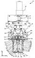
- FIG. 1is a front view of an extrusion based layered deposition system having a pantograph assembly for producing replica three-dimensional parts.
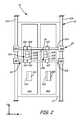
- FIG. 2is a top view of a gantry system having dual extrusion heads for use in the pantograph assembly of FIG. 1 .
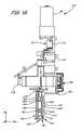
- FIG. 3Ais a front view of an extrusion head having a stationary extruder and a movable extruder connected by a hinge mechanism in the pantograph assembly of FIGS. 1 and 2 .
- FIG. 3Bis a side view of the extrusion head of FIG. 3A showing assembly of the movable extruder and an actuation motor.
- FIG. 3Cis a bottom view of the extrusion head of FIG. 3A in which alignment of the movable extruder with the stationary extruder is shown.
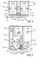
- FIG. 4is a front view of a stationary extruder and a movable extruder connected by a hinge mechanism used in the extrusion head of FIGS. 3A-3C .
- FIG. 5is a rear perspective view of the stationary extruder and the movable extruder of FIG. 4 showing assembly of the hinge mechanism and the extrusion head.
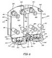
- FIG. 6is a front perspective view of the hinge mechanism of FIG. 4 shown with components of the stationary and movable extruders omitted such that a top of the hinge mechanism is visible.
- FIG. 7is a diagrammatic side view of the hinge mechanism of FIG. 6 showing interaction of an interference feature with the hinge mechanism to limit movement of the moveable extruder.
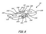
- FIG. 8is a perspective view of a second embodiment of a hinge mechanism for connecting stationary and movable extruders in a dual extruder head assembly.
- FIG. 1is a front view of extrusion based layered deposition system 10 having dual deposition heads 12 A and 12 B of the pantograph assembly of the present invention.
- Deposition system 10comprises cabinet 14 having door 16 that together enclose build chamber 18 in a suitable build environment.
- Deposition system 10also includes gantry 20 and platen 22 , which are disposed within build chamber 18 behind door 16 .
- Suitable deposition systems for use with the present inventioninclude fused deposition modeling systems developed by Stratasys, Inc., Eden Prairie, Minn.
- Deposition heads 12 A and 12 Binclude dual tip extruders 24 A and 24 B, respectively, which are configured to receive strands of extrusion material from filament load systems 25 A and 25 B.
- Controller 27commands movement and controls operation of heads 12 A and 12 B and load systems 25 A and 25 B such that extruders 24 A and 24 B simultaneously deposit layers of extrusion material onto a substrate, such as platen 22 , to build replica three-dimensional objects 26 A and 26 B.
- Platen 22 and gantry 20are configured to move deposition heads 12 A and 12 B in three-dimensional space, as defined by an (X, Y, Z) Cartesian coordinate system, relative to platen 22 .
- platen 22includes lifters 28 , such as electric motors and lead screws, that move platen 22 in a Z-direction orthogonal to an (X,Y) plane defined by gantry 20 .
- Gantry 20comprises a guide rail system having Y-bridge 30 and X-bridge 32 that define a headspace within which heads 12 A and 12 B move. Heads 12 A and 12 B move within the (X,Y) plane above platen 22 through a motorized drive system (not shown), as is known in the art.
- Controller 27which typically comprises a computer-operated system, coordinates operation of the motorized drive system and lifters 28 based on (X,Y,Z)-coordinate build data derived from the geometry of objects 26 A and 26 B.
- build datais typically derived from a digital CAD model representing objects 26 A and 26 B.
- dual tip extruders 24 A and 24 Bdeposit incremental layers of material onto platen 22 to build 3D of objects 26 A and 26 B.
- Objects 26 A and 26 Bcomprise replica parts, such as production manufacturing components or rapid prototypes, which often include complex geometries extending into space, as defined by the (X, Y, Z) Cartesian coordinate system.
- the geometriesoften result in deposited layers of the material being wider or laterally displaced in the (X, Y) plane than the previous layers such that the deposited layers are unsupported by the previous layers.
- the supportsare themselves comprised of layers of extrusion material deposited onto platen 22 by dual tip extruders 24 A and 24 B.
- Filament load systems 25 A and 25 Binclude multiple filament feed spools that are configured to deliver multiple strands of build and support material to heads 12 A and 12 B, respectively, such as through a flexible feed tube.
- filament load systems 25 A and 25 Bcomprise feed systems described and referenced in U.S. Pat. Nos. 6,923,634 to Swanson, et al. and 6,022,207 to Dahlin, et al., which are assigned to Stratasys, Inc., Eden Prairie, Minn.
- Deposition heads 12 A and 12 Binclude dual tip extruders 24 A and 24 B, respectively, which are configured to deposit the build material and the support material in planar (X, Y) layers to form replica objects 26 A and 26 B and supports 34 A and 34 B, respectively.
- Extruders 24 A and 24 Bare supplied with similar build and support materials so extrusion head 12 B deposits material with the same flow dynamics as extrusion head 12 A.
- the materials for extruders 24 A and 24 Bshould have similar thermal profiles such that the layers comprising objects 26 A and 26 B are built up in the same fashion.
- the materials, however,need not be identical so they can be, for example, different colors.
- Heads 12 A and 12 Brespectively include umbilical systems 35 A and 35 B, which provide independent electronic communication with controller 27 such as for providing power to heads 12 A and 12 B and operating extruders 24 A and 24 B.
- controller 27such as for providing power to heads 12 A and 12 B and operating extruders 24 A and 24 B.
- head 12 Ais mechanically linked to head 12 B with pantograph connector 36 in a trailer-like configuration.
- Controller 27 and the motorized drive systemneed only directly manipulate head 12 A on gantry 20 .
- heads 12 A and 12 Bcomprise a pantograph extrusion head system in which head 12 A is an individually operable robot and connector 36 rigidly connects head 12 B to head 12 A such that movement of head 12 A in the (X-Y) plane results in head 12 B undergoing the same displacements in the (X-Y) plane.
- controller 27need only operate a single motorized drive system to manipulate both of heads 12 A and 12 B.
- heads 12 A and 12 Beach include motorized drive systems, such as two-dimensional linear stepper motors, and are independently operated by controller 27 .
- motorized drive systemssuch as two-dimensional linear stepper motors
- controller 27particular attention must be given to developing collision avoidance rules to avoid interference between heads 12 A and 12 B.
- multiple dual tip extrudersare incorporated into a single head such that only a single motorized drive system is needed. The need for development of collision avoidance rules can be avoided in single motorized drive systems, such as in the single head embodiment and the dual head trailer embodiment shown in FIG. 1 , however, by dividing platen 22 into distinct workspaces for extruders 24 A and 24 B, as is discussed in detail with reference to FIG. 2 .
- FIG. 2is a top view of gantry 20 for use in extrusion based layered deposition system 10 .
- Gantry 20is displaced in the Z-direction above platen 22 to manipulate the pantograph assembly of heads 12 A and 12 B in the (X-Y) plane.
- Gantry 20comprises Y-bridge 30 , which comprises rails 30 A and 30 B, and X-bridge 32 , which comprises rails 32 A and 32 B.
- Rails 32 A and 32 B of X-bridge 32are fixed such that they are stationary inside build space 18 with respect to cabinet 14 ( FIG. 1 ).
- Rails 30 A and 30 B of Y-bridge 30are joined to rails 32 A and 32 B through bearings 38 A- 38 D.
- Heads 12 A and 12 Bare configured to ride on rails 30 A and 30 B through bearings 40 A- 40 F. Heads 12 A and 12 B are linked by pantograph connector 36 and include dual tip extruders 24 A and 24 B, respectively. Dual tip extruder 24 A includes stationary extruder 42 A and movable extruder 44 A, and dual tip extruder 24 B includes stationary extruder 42 B and movable extruder 44 B. Platen 22 comprises a substrate partitioned into workspaces 46 A and 46 B upon which extruders 42 A- 44 B are configured to deposit build and support materials. Heads 12 A and 12 B are connected in a pantograph assembly through their linkage with connector 36 and gantry 20 to build replica objects 26 A and 26 B, respectively, on workspace 46 A and workspace 46 B.
- Workspaces 46 A and 46 Bcomprise zones of platen 22 within which heads 12 A and 12 B are configured to operate. More specifically, workspaces 46 A and 46 B comprise build areas to which extruders 42 A and 44 A, and 42 B and 44 B, respectively, have complete access without encumbrance from gantry 20 and the head to which they are not mounted. For example, workspace 46 A comprises a “fenced” area through which extruders 42 B and 44 B will never pass during building of object 26 A and support 34 A. Although partitioning of platen 22 into distinct build zones restricts the size of parts that can be produced with system 10 , workspaces 46 A and 46 B facilitate fitting of gantry 20 with both deposition head 12 A and deposition head 12 B.
- a typical extrusion based layered deposition systemis designed having a build envelope, as defined by the size of build chamber 18 , that would encompass ninety-five percent of the parts to be produced by a particular manufacturer. As such, most of the workspace defined by platen 22 is unused in the production of a typical single part. There is, therefore, space available on platen 22 for building additional parts.
- typical extrusion based layered deposition systemsinclude a gantry system that is designed with stiffnesses, clearances and tolerances for positioning a variety of extrusion heads having varying masses.
- the stiffnesses of the bridge rails, and the clearances between the bridge rails and the deposition headsare sized to accommodate much larger deposition heads than are often used in a particular system.
- a typical gantryis designed with significant margin in the mass that the drive system is capable of accurately positioning. There is, therefore, load capacity available on gantry 20 for supporting additional extrusion heads.
- the drive systemhas capacity for moving additional mass.
- extrusion based layered deposition 10utilizes the excess capacities of gantry 20 , the motorized drive system and platen 22 to accommodate a second extrusion head that is connected through a pantograph assembly to build a second identical, or nearly identical, object on platen 22 .
- multiple pantograph extrusion headscan be added to gantry 20 , depending on the size of the extrusion heads and the capacities of gantry 20 and the motorized drive system.
- the part sizes for each of the objectsis limited such that no object will overlap or overhang the workspace for another object to ensure collision avoidance.
- the pantograph assembly of the present inventioncan be easily incorporated as an upgrade to existing machines by connecting head 12 B to an existing head with connector 36 .
- a typical extrusion headincludes four bearings, positioned similarly to bearings 40 A- 40 D shown in FIG. 2 , to provide proper stability on rails 30 A and 30 B.
- Head 12 B of the present inventionneed only include two bearings, bearings 40 E and 40 F, to provide stability when linked with head 12 A through connector 36 .
- Connector 36thus needs to rigidly connect head 12 B to head 12 A to remove any slop between movement of head 12 A and head 12 B.
- Connector 36comprises a rigid beam produced of any suitably stiff material and is connected to heads 12 A and 12 B by any suitable rigid connection.
- Connector 36can also be configured to be expediently disconnected from heads 12 A and 12 B such that system 10 can convert easily between single and replica manufacturing.
- connector 36is disconnected from head 12 A such that head 12 B can be parked on Y-bridge 30 in an out of the way position, such as near bearings 38 B and 38 D.
- Connector 36is also disconnected from head 12 B to avoid interference with movement of head 12 A.
- typical single head extrusion based layered deposition systemsincorporate four filament feed spools: two for dispensing build material, and two for dispensing support material.
- An automatic change-over mechanismallows the second spool of each type to feed when the first is exhausted.
- the same four spoolscan feed the now four liquefiers without the automatic change-over option.
- four additional spoolsare installed into the filament loading system.
- each of the four spoolsis co-wound with as many filaments as installed deposition heads, preferably in a zip-cord configuration, so that no additional spools are needed.
- head 12 A and head 12 Bcan each include two bearings to ride on rails 30 A and 30 B and connector 36 is semi-permanently attached to both heads.
- system 10can be designed as a pantograph assembly with gantry 20 , head 12 A, head 12 B and connector 36 custom designed for replica manufacturing, rather than as attachments or upgrades to existing single manufacturing systems.
- extrusion based layered deposition systemsalso include other system components for facilitating replica manufacturing.
- system 10includes additional purging and wiping systems.
- one purge bucket and one tip wiperis located within build space 18 so that each deposition head has access. Such a system, however, has potential for violating collision avoidance rules.
- a tip wiper and purge bucketare themselves movable in build space 18 to avoid collision with extrusion heads 12 A and 12 B or objects 26 A and 26 B.
- tip wipers and purge bucketsare provided in build space 18 for each of heads 12 A and 12 B so that purging and tip wiping for nozzles 68 A and 68 B can be conducted in parallel.
- a typical extrusion based layered deposition systemincludes a thermal barrier system for isolating build space 18 from gantry 20 .
- a typical thermal barrier systemincludes four sections of a flexible thermal barrier bellows that surround the extrusion head. Two flexible bellows provide separation of build space 18 for movement of the head in the Y-direction, and two flexible bellows provide separation of build space 18 for movement of the head in the X-direction.
- Such a systemis illustrated in the aforementioned U.S. Pat. No. 6,722,872.
- head 12 BWith the addition of an additional extrusion head, such as head 12 B, a gap is produced in the bellows between the head.
- a fifth, inflexible thermal barrier sectionis added between the heads.
- the pantograph assemblyis used to produce customized parts that have different features built on common platforms.
- the replica manufacturing headsproduce in parallel the platform portions of customized parts that have common features.
- the extrusion headsproduce in series the customized features on the platform portions.
- the customized portionscan be produced serially either by using both the first and second deposition heads, such as in a dedicated replica manufacturing system, or by using only the first deposition head, such as in an upgraded manufacturing system, after removing the replica deposition head.
- extrusion heads 12 A and 12 BUpon initiation of a build operation, extrusion heads 12 A and 12 B are positioned above workspace 46 A and workspace 46 B, respectively. Heads 12 A and 12 B are set to a build state in which dual tip extruders 24 A and 24 B are configured to deposit build material with extruders 42 A and 42 B. Extruders 42 A and 42 B deposit the build material in a sequence of roads to form a first, single layer for each of objects 26 A and 26 B. After the first layers of build material are completed, extrusion heads 12 A and 12 B are then toggled to a support state, which allows dual tip extruders 24 A and 24 B to deposit support material with extruders 44 A and 44 B.
- Extruders 44 A and 44 Bdeposit the support material in a sequence of roads to form a first, single layer for each of supports 34 A and 34 B upon which subsequent layers of build or support material will be deposited during the fabrication of objects 26 A and 26 B.
- Connector 36tethers head 12 B to head 12 A so that head 12 B mimics the movements of head 12 A in the (X, Y) plane.
- extruders 42 B and 44 Bmimic the movements of extruders 42 A and 44 A to produce duplicate build and support layers for objects 26 A and 26 B.
- platen 22is adjusted in the Z-direction such that subsequent layers of build and support material can be deposited atop the first layers.
- platen 22is lowered in the Z-direction, or brought further away from gantry 20 , by lifters 28 ( FIG. 1 ) such that the Z-direction distance between the first layers of deposited material and gantry 20 will be approximately equal to the distance between platen 22 and gantry 20 before the first layers of material were deposited.
- platen 22is moved a distance equal to the thickness of a single layer of deposited material, which may vary from object to object depending on material and the part being produced.
- gantry 20can be configured to translate in the Z-direction, while platen 22 remains stationary within cabinet 14 ( FIG. 1 ). While platen 22 adjusts the Z-direction relationship between gantry 20 and workspaces 46 A and 46 B, controller 27 ( FIG.
- the drive systemdirectly manipulates head 12 A on gantry 24 to move dual tip extruder 14 A in the (X, Y) plane based on the build data.
- the layering processis repeated until each layer of objects 26 A and 26 B and supports 34 A and 34 B are completed.
- objects 26 A and 26 Bare removed from build chamber 18 .
- Supports 34 A and 34 Bare typically adhered to objects 26 A and 26 B, respectively.
- the support materialis selected to easily be pulled or broken away from the build material when properly solidified.
- finished object 26 Bwill be identical, or nearly identical within acceptable tolerance limits, to finished object 26 A due, in part, to the tethering effects of the pantograph assembly, including connector 36 .
- extruders 42 A and 42 B, and extruders 42 B and 44 Bare provided with respective hinge mechanisms to replicate toggling of heads 12 A and 12 B between the build state and the support state.
- FIG. 3Ais a front view of extrusion head 12 A having stationary extruder 42 A and movable extruder 44 A coupled to head body 48 for use in the pantograph assembly of FIGS. 1 and 2 .
- FIG. 3Bis a side view of extrusion head 12 A of FIG. 3A .
- FIG. 3Cis a bottom view of extrusion head 12 A of FIG. 3A .
- FIGS. 3A-3Care discussed concurrently and show an extrusion head representative of both heads 12 A and 12 B.
- Head body 48connects to stationary extruder block 50 A and movable extruder block 50 B, which is configured to toggle movable extruder 44 A with respect to stationary extruder 42 A between a build state and a support state.
- Head 12 Ais provided with a pair of linkages that facilitate toggling of movable extruder 44 A.
- Connector 52comprises a rigid linkage that maintains the upper end of movable extruder 44 A spaced from stationary extruder 42 A in the X-direction.
- Hinge mechanism 54comprises a flexible linkage that constrains three-dimensional movement of extruder 44 A such that the displacement of movable extruder 44 A can be replicated in head 12 B ( FIG. 2 ).
- Head 12 Aalso includes motor bracket 56 , extruder motor 58 , stationary feed motor 60 A, movable feed motor 60 B, stationary feed system 62 A and movable feed system 62 B.
- Head body 48comprises a base block upon which the components of head 12 A are mounted, and is mounted to Y-bridge 30 with bearings 40 A- 40 D ( FIG. 2 ). Head body 48 thus does not move in the Z-direction with respect to Y-bridge 30 or gantry 20 , but rather translates in the (X, Y) plane within the headspace.
- stationary extruder 42 Ais configured to extrude build material for fabricating object 26 A
- movable extruder 44 Ais configured to extrude support material for fabricating support 34 A.
- suitable materials for use with the present inventioninclude any type of extrudable material (e.g., thermoplastic materials).
- Suitable build and support materials for use with the present inventionare described in U.S. Pat. No. 7,122,246 to Comb et al., which is assigned to Stratasys, Inc.
- the build material and support materialare different from each other in that they have different thermal profiles in order to, for example, be easily separated after solidification.
- movable extruder 44 Ais spatially and thermally separated from stationary extruder 42 A.
- movable extruder 44 Acomprises liquefier tube 64 B, which extends through and is brazed to liquefier block 66 B.
- Extrusion nozzle 68 Bis positioned at an end of liquefier tube 64 B to dispense material from extruder 44 A.
- Heater 70 Bwhich in one embodiment comprises a ceramic heater, extends the length of liquefier block 66 B to melt or liquefy support material within liquefier tube 64 B.
- Movable extruder 44 Aalso includes cover plate 72 B, which acts as a heat shield to prevent heat from escaping liquefier block 66 B, and nozzle shield 74 B, which comprises a TEFLON® shield from which accumulated extrusion material is easily removed. Cover plate 72 B and nozzle shield 74 B also prevent burning or melting of already deposited material.
- Stationary extruder 42 Aincludes similar components, such as liquefier tube 64 A, extrusion nozzle 68 A, heater 70 A, cover plate 72 A and nozzle shield 74 A. Further explanation of liquefier tubes and heaters suitable for use in the present invention is provided in U.S.
- Feed system 62 A and feed system 62 Bare configured to deliver continuous filament strands or a series of filament segments of extrusion material to liquefier tubes 64 A and 64 B.
- movable feed system 62 Bincludes wheels 76 B, between which a filament is pushed into liquefier tube 64 B. Wheels 76 B are driven by gear system 78 B, which is powered by movable feed motor 60 B.
- Stationary extruder 42 Aincludes similar components, such as wheels 76 A and gear system 78 A.
- Feed motors 60 A and 60 Beach also include a position encoder, a driver and a feedback loop with controller 27 ( FIG. 1 ), respectively. The extrusion rate of head 12 A is balanced to that of head 12 B ( FIG.
- Extrusion material from loading systems 25 A and 25 B( FIG. 1 ) is fed into liquefier tubes 64 A and 64 B with mechanical force by wheels 76 A and 76 B.
- Solid filamententers liquefier tubes 64 A and 64 B at one end, is melted by heaters 70 A and 70 B, and is extruded through nozzles 68 A and 68 B as liquefied material.
- extruders 44 A and 44 Brequire thermal gradients to produce melted extrusion material. Heated material is needed near nozzles 68 A and 68 B, while cooled material is needed near wheels 76 A and 76 B.
- each additional deposition headsuch as head 12 B, includes a similarly positioned bellows tube.
- heads 12 A and 12 Bare provided with thermoelectrics to electrically pump heat away from the cool end of extruders 44 A and 44 B to a convector, which is then cooled by circulating heated ambient air of the build chamber by the convector.
- each extruder 44 A and 44 Bincludes a temperature sensor for providing temperature control feedback to controller 27 . Further explanation of feed systems suitable for use in the present invention is provided in U.S. Pat. No.
- Extruders 42 A and 44 Aare configured to deliver liquefied build and support material to platen 22 ( FIG. 2 ) to build up objects 26 A and 26 B and supports 34 A and 34 B.
- head 12 Ais configured to be adjusted between a build state and a support state, where extruder 42 A deposits build material for object 26 A in the build state and extruder 44 A deposits support material for support 34 A in the support state.
- Stationary extruder block 50 Ais directly coupled to head body 48 with, for example, threaded fasteners extending through stationary extruder block 50 A at opening 80 .
- Stationary extruder 42 Ais coupled to extruder block 50 A with angle bracket 82 A.
- Angle bracket 82 Ais joined to back plate 84 A with studs 86 A and 86 B (positioned behind studs 87 A and 87 B in FIG. 3B and shown in FIG. 6 ).
- Standoffs 88 A- 88 Djoin back plate 84 A with cover plate 72 A, between which is positioned liquefier block 66 A and heater 70 A.
- stationary extruder 42 Ais rigidly connected to head body 48 and thus moves where head body 48 moves.
- stationary extruder 42 Ais stationary in the Z-direction with respect to gantry 20 .
- Movable extruder block 50 Bis coupled to head body 48 through extruder motor 58 and jack assembly 90 .
- Jack assembly 90includes a threaded screw (not shown) that is driven by motor 58 .
- the threaded screwextends through head body 48 at opening 80 to engage movable extruder block 50 B.
- Extruder block 50 Balso includes a bearing shaft (not shown) that extends into a bore in head body 48 .
- movable extruder block 50 Bis configured to translate linearly in the Z-direction relative to head body 48 and gantry 20 .
- Movable extruder 44 Ais coupled to extruder block 50 B with angle bracket 82 B.
- Angle bracket 82 Bis joined to back plate 84 B with studs 87 A and 87 B.
- Standoffs 89 A- 89 Djoin back plate 84 B with cover plate 72 B, between which is positioned liquefier block 66 B and heater 70 B.
- movable extrudertranslates in the Z-direction with extruder block 50 B.
- Manipulation of movable extruder body 50 B by extruder motor 58is coordinated by controller 27 ( FIG. 1 ) in conjunction with actuation of platen 22 ( FIG. 1 ) by lifters 28 .
- controller 27FIG. 1
- movable extruder body 50 Bis actuated in the Z-direction to extend movable nozzle 68 B beyond stationary nozzle 68 A.
- movable nozzle 68 Balso becomes positioned closer to platen 22 than stationary nozzle 68 A.
- Platen 22must be translated in the Z-direction an amount equal to the distance nozzle 68 B is positioned below nozzle 68 A so that the support material deposited by nozzle 68 B is deposited in the same plane, with respect to platen 22 , as the build material is deposited by nozzle 68 A of stationary extruder 42 A. It is desirable to be able to consistently actuate movable extruder body 50 B in the Z-direction so that platen 22 can be adjusted commensurately with movement of nozzle 68 B. Furthermore, in replica manufacturing where two heads are producing two identical parts, it is also desirable to replicate the movement of movable extruder 44 B ( FIG.
- extruder 42 A and extruder 44 Ashould be the same distance above platen 22 when active, which may be slightly different than the distance extruders 42 B and 44 B are above platen 22 when active.
- Hinge mechanism 54connects nozzle 68 A with nozzle 68 B on each head to maintain the spatial relationships between the nozzles within a small tolerance range that is acceptable for the given objects 26 A and 26 B being produced.
- deposition head 12 Ais provided with connector 52 and hinge mechanism 54 to guide toggling of movable extruder 44 A between the build state and the support state.
- Connector 52comprises a pinned connector that is allowed to pivot on stationary extruder 42 A and movable extruder 44 A at standoffs 88 A and 89 A.
- Connector 52is loosely pinned such that connector 52 provides coarse alignment of movable extruder 44 A with stationary extruder 42 A.
- Connector 52maintains extruder 44 A in an upright position and aligns liquefier tube 64 A with wheels 76 A of feed system 62 A to facilitate feeding of extrusion material filaments.
- Hinge mechanism 54provides fine alignment of movable extruder 44 A with stationary extruder 42 A such that the spatial relationship between nozzle 68 A and 68 B in the support state is known and replicable.
- hinge mechanism 54assists in maintaining nozzle 68 B in a known position with respect to nozzle 68 A for three parameters: a distance d (X,Y) between the nozzles in the (X, Y) plane ( FIG. 3C ), an angle ⁇ of a line extending through the nozzles with respect to gantry 20 ( FIG. 3C ), and a distance d (Z) between the tips of the nozzles with respect to the Z-direction ( FIG. 4 ).
- FIG. 3Cillustrates the relationship of nozzles 68 A and 68 B with reference to distance d (X,Y) and angle ⁇ .
- Distance d (X,Y)represents the absolute distance between nozzle 68 A and nozzle 68 B in the (X, Y) plane, without reference to the heights of nozzles 68 A and 68 B in the Z-direction, or the orientation of extruder 24 A in the (X, Y) plane.
- Distance d (X,Y)thus comprises a vector typically having a substantial X-direction component and a minor Y-direction component.
- Angle ⁇represents the orientation of extruder 24 A and nozzles 68 A and 68 B in the (X, Y) plane with respect to gantry 20 ( FIG. 2 ).
- gantry 20is positioned above platen 22 such that Y-Bridge 30 and X-bridge 32 are orthogonal to each other and the Z-direction.
- the X-axisextends generally parallel to X-bridge 30 .
- Line lextends through the centers of nozzles 68 A and 68 B at angle ⁇ with respect to the reference X-direction axis.
- Angle ⁇comprises an indication of how far in the Y-direction nozzle 68 B is offset from nozzle 68 A.
- FIG. 4is a front view of stationary extruder 42 A and movable extruder 44 A connected by hinge mechanism 54 .
- FIG. 4illustrates the relationship of stationary nozzle 68 A and movable nozzle 68 B with reference to distance d (Z) .
- Extruders 42 A and 44 Aare suspended from extruder blocks 50 A and 50 B ( FIG. 3A ) by angle brackets 82 A and 82 B, respectively.
- Liquefier tubes 64 A and 64 Bextend through extruders 42 A and 42 B behind cover plates 72 A and 72 B and up to nozzles 68 A and 68 B, respectively.
- Nozzles 68 A and 68 Bextend through nozzle shields 74 A and 74 B, respectively, such that their tips form the downward-most extent of extruders 42 A and 44 A in the Z-direction.
- FIG. 4shows movable extruder 44 A in an arbitrary position between the build state and the support state. In the support state, movable extruder 44 A is positioned in a lower position such that nozzle 68 B is below nozzle 68 A and distance d (Z) has a positive value. In the build state, movable extruder 44 A is positioned in an upper position such that nozzle 68 B is above nozzle 68 A and distance d (Z) has a negative value.
- Hinge mechanism 54ensures that every time movable extruder 44 A is fully positioned in the build state, distance d (Z) is the same to within an acceptable tolerance. In one embodiment, hinge mechanism 54 ensures that movable nozzle 68 B is positioned below stationary nozzle 68 A a distance d (Z) to within a tolerance of approximately 0.001 inches ( ⁇ 0.025 mm) in the support state. Hinge mechanism 54 , which is discussed in greater detail with reference to FIGS. 5 and 6 , comprises stationary yoke 92 A, movable yoke 92 B, link 94 A, fasteners 95 A and 95 B, and interference feature 96 .
- FIG. 5is a rear perspective view of stationary extruder 42 A and movable extruder 44 A of FIG. 4 showing assembly of hinge mechanism 54 with back plates 84 A and 84 B.
- Hinge mechanism 54comprises stationary yoke 92 A, movable yoke 92 B, link 94 B and fasteners 95 C and 95 D.
- Back plates 84 A and 84 Bare connected to angle brackets 82 A and 82 B, respectively. As discussed with reference to FIGS.
- angle bracket 82 Ais fixedly attached to extruder block 50 A such that nozzle 42 A is three-dimensionally stabilized
- angle bracket 82 Bis adjustably attached to extruder block 50 B through jack assembly 90 , which does not provide three-dimensional stability to movable extruder 44 A.
- Fastener 97which is connected to stud 87 A (not shown) connects back plate 84 B to angle bracket 82 B, and thus provides the actuating force for movement of extruder 44 A in the Z-direction.
- Fastener 97does not, however, stabilize plate 84 B.
- the Z-direction position, or distance d (Z)of plate 84 B is dictated by the precision with which jack assembly 90 ( FIG.
- Connector 52provides rotational stability to an upper portion of plate 84 B, while hinge mechanism 54 provides further restraint on movement of back plate 84 B and nozzle 68 B.
- Stationary yoke 92 Ais connected to back plate 84 A with, for example, threaded fasteners at bores 98 A.
- movable yoke 92 Bis connected to back plate 84 B with, for example, threaded fasteners at bores 98 B.
- Yokes 92 A and 92 Bare substantially parallel to the bottom surfaces of plates 84 A and 84 B such that yokes 92 A and 92 B are orthogonal to the Z-direction.
- Yokes 92 A and 92 Bextend perpendicularly from plates 84 A and 84 B to receive nozzles 68 A and 68 B.
- Yokes 92 A and 92 Bare connected by link 94 A and fasteners 95 A and 95 B ( FIG. 4 ), and link 94 B and fasteners 95 C and 95 D ( FIG. 5 ).
- Yokes 92 A and 92 B, and links 94 A and 94 Bassemble to form a double action hinge that, with the addition of interference feature 96 , stabilizes the position of nozzle 68 B in the build state of head 12 A.
- FIG. 6is a front perspective view of hinge mechanism 54 of FIG. 4 shown with cover plates, liquefier blocks, and liquefier tubes omitted such that top surfaces of stationary yoke 92 A and movable yoke 92 B are visible.
- Hinge mechanism 54includes links 94 A and 94 B, fasteners 95 A and 95 B, interference feature 96 , and nozzle pockets 100 A and 100 B.
- Back plate 84 Ais connected to angle bracket 82 A through studs 86 A and 86 B such that stationary extruder 42 A is stationary in the Z-direction.
- Back plate 84 Bis connected to angle bracket 82 B through stud 87 A such that movable extruder 44 A is adjustable in the Z-direction.
- Movable extruder 44 Ais connected to stationary extruder 42 A with connector 52 and hinge mechanism 54 .
- Connector 52pivots about standoffs 88 A and 89 A at upper portions of back plates 84 A and 84 B to maintain movable extruder 44 A in an upright position and spaced from stationary extruder 42 A.
- Movable nozzle 68 Bis maintained in a known spatial relationship with respect to stationary nozzle 68 A through hinge mechanism 54 .
- Stationary yoke 92 A and movable yoke 92 Bare rigidly connected to back plates 84 A and 84 B, respectively, and provide shelves for receiving nozzles 68 A and 68 B.
- nozzle pockets 100 A and 100 Bare recessed into yokes 92 A and 92 B, respectively, to allow liquefier blocks 66 A and 66 B to be secured within yokes 92 A and 92 B.
- Pockets 100 A and 100 Binclude bores 102 A and 102 B for receiving nozzles 68 A and 68 B.
- Nozzles 68 A and 68 Bfit snuggly within bores 102 A and 102 B while flanges 104 A and 104 B prevent nozzles from passing through yokes 92 A and 92 B.
- Nozzles 68 A and 68 Bcomprise orifii that receive extrusion materials from liquefier tubes 64 A and 64 B to regulate dispensing of the material.
- Nozzles 68 A and 68 Bare typically necked down at their tips so that the extrusion material can be dispensed during an extrusion operation in beads or roads of a diameter smaller than the diameter of tubes 64 A and 64 B.
- stationary nozzle 68 Ais held generally orthogonally above platen 22 ( FIG. 1 ) by the relative parallel relationship between stationary yoke 92 A and platen 22 .
- stationary extruder 42 Adeposits roads of build material perpendicularly to platen 22 .
- movable extruder 44 Ais retracted such that nozzle 68 B is positioned above nozzle 68 A in the Z-direction.
- a side surface of movable yoke 92 Acomes to rest against a side surface of stationary plate 92 .
- nozzle 68 BIn the build state, it is not necessary for nozzle 68 B to be positioned precisely above nozzle 68 A because it is not actively depositing extrusion material onto platen 22 . Nozzle 68 B, as well as all of extruder 44 A, need only be positioned out of the way of nozzle 68 A so as to not interfere with the active extrusion process. In the support state, however, as discussed above, nozzle 68 B is positioned precisely below nozzle 68 A using interference feature 96 .
- angle bracket 82 Bis lowered by jack assembly 90 ( FIG. 1 ). Movable nozzle is lowered toward platen 22 and is held generally perpendicularly above platen 22 by the relative parallel relationship between movable yoke 92 B and platen 22 . Due to the double action hinge provided by links 94 A and 94 B, movable yoke 92 B is maintained generally parallel to platen 22 throughout the transition process. In another embodiment, links 94 A and 94 B are replaced with linkages comprising segments of flexible spring steel. In any embodiment, however, movable yoke 92 B is permitted to translate parallel to platen 22 .
- Links 94 A and 94 Balso guide movable yoke 92 B along an arcuate trajectory while being lowered, the radius of which is dictated by the length of links 94 A and 94 B.
- flange 106 of interference feature 96engages stationary yoke 92 A to stop further movement of nozzle 68 B in the Z-direction.
- Flange 106is displaced in the Z-direction from movable plate 92 B by pedestal 108 such that movable plate 92 B is positioned lower than stationary plate 92 A.
- links 94 A and 94 Bprevent movable plate 92 B from moving closer to stationary plate 92 A in the (X, Y) plane.
- FIG. 7is a diagrammatic side view of hinge mechanism 54 of FIG. 6 showing interaction of interference feature 96 with stationary yoke 92 A to inhibit movement of movable yoke 92 B.
- Link 94 Ais shown in phantom in FIG. 7 and fasteners 95 A and 95 B are omitted to show more clearly interference feature 96 .
- Interference feature 96comprises planar flange 106 that is displaced from movable yoke 92 B by pedestal 108 .
- Pedestal 108projects from movable yoke 92 B in the in the Z-direction. Pedestal 108 is positioned on movable yoke 92 B along a side adjacent stationary yoke 92 A.
- Flange 106projects from pedestal 108 in the (X, Y) plane so as to extend above stationary yoke 92 A.
- a bottom surface of flange 106engages a top surface of stationary yoke 92 A.
- flange 106interferes with the capacity of movable yoke 92 B to translate downward in the Z-direction.
- movable yoke 92 Bis limited in moving below stationary yoke 92 A the distance between the bottom surface of flange 106 and the top surface of yoke 92 B.
- the hinge distance d H(Z) to which movable yoke 92 B moves beneath stationary yoke 92 A, or the Z-direction distance between the centers of yokes 92 A and 92 Bis equivalent to distance d (Z) between nozzles 68 A and 68 B ( FIG. 4 ).
- Interference feature 96thus replaces the need for measuring distance d (Z) and placing shims within extruder 44 A or head 12 A to fix distance d (Z) .
- Hinge mechanism 54also fixes distance d (X, Y) between nozzles 68 A and 68 B ( FIG. 3C ) through engagement of interference feature 96 with yoke 92 A in the support state.
- yoke 92 A and 92 Bare coplanar, the hinge distance d H(X,Y) between yokes 92 A and 92 B is greatest. From such a position, arcuate trajectory t of movable yoke 92 B, which is dictated by link 94 A, brings movable plate 92 B toward contact with stationary plate 92 A.
- Flange 102prevents further downward or Z-direction movement of movable yoke 92 B such that further movement along trajectory t tends to pushe movable yoke 92 B toward stationary yoke 92 A.
- Links 94 A and 94 Bprevent yoke 92 B from moving any closer to yoke 92 A due to their engagement with screws 95 A and 95 B.
- links 94 A and 94 Bare put into compression between screws 95 A and 95 B by the force pushing movable yoke 92 B toward yoke 92 A, the force actuating extruder 44 A.
- hinge distance d H(X,Y)shortens so that movable yoke 92 B cannot become any closer to stationary plate 92 A, thus fixing the distance d (X,Y) between nozzles 68 A and 68 B ( FIG. 4 ).
- the widths w of links 94 A and 94 B, and the heights h of yokes 92 A and 92 Bdetermine the mode through which yokes 92 A and 92 B will engage.
- links 94 A and 94 Bmust be sized wide enough to allow jack assembly 90 to translate movable extruder 44 A from the build state to the support state, and the heights of yokes 92 A and 92 B must be selected to ensure that flange 106 will engage stationary plate 92 A.
- the width w of links 94 A and 94 Bis selected to be the length of the hypotenuse of a right triangle having sides with lengths equaling hinge distances d H(X,Y) and d H(Z) .
- Yokes 92 A and 92 Bthen, must have heights h that enables flange 106 to engage yoke 92 A.
- Hinge mechanism 54also assists in limiting movement of yoke 92 B in the (X, Y) plane such that angle ⁇ ( FIG. 3C ) is inhibited from changing.
- links 94 A and 94 Binhibit movable yoke 92 B from translating in the Y-direction by the use of right angles and shoulder screws for fasteners 95 A and 95 B.
- yokes 92 A and 92 B, and links 94 A and 94 Bcan be fabricated to a precise level such that tolerance stack-ups are within an acceptable range, such as approximately +/ ⁇ 0.002 inches ( ⁇ 0.051 mm).
- Fasteners 95 A and 95 Bcomprise shoulder screws that are tightly secured to yokes 92 A and 92 B while also permitting links 94 A and 94 B to pivot.
- hinge mechanism 54is manually shimmed to ensure that angle ⁇ is the same in heads 12 A and 12 B ( FIG. 2 ), i.e. that movable extruders 44 A and 44 B are positioned similarly with respect to stationary extruders 42 A and 42 B in the (X, Y) plane.
- angle bracket 82 Bcan be rotated on its connection with movable extruder block 50 B ( FIG. 3B ) to adjust the placement of back plate 84 B in the Y-direction and angle ⁇ .
- hinge mechanism 54is substituted with a plate that is fixed to stationary extruder 42 A and that is wide enough to include a pair of bores that are set at a fixed distance for receiving extrusion tubes 64 A and 64 B ( FIG.
- Movable liquefier tube 64 Bwould be inserted and withdrawn from one of the bores as movable extruder 44 A is toggled between the build and support states. In such an embodiment, however, movable liquefier tube 64 B needs to be precisely aligned with the fixed bore. Additionally, steps must be taken to prevent extrusion material from accumulating on the fixed plate. In another embodiment, other double action hinges can be used, as is shown in FIG. 8 .
- FIG. 8is a perspective view of hinge mechanism 110 for connecting stationary and movable extruders in a dual extruder head assembly.
- Hinge mechanism 110includes first yoke 112 A, second yoke 112 B, link 114 A, link 114 B, fasteners 116 A- 116 D, nozzle bores 118 A and 118 B, fastening bores 120 A- 120 D, and interference feature 122 .
- Hinge mechanism 110is similar to hinge mechanism 54 in that yokes 112 A and 112 B are connected by links 114 A and 114 B to form a dual hinge mechanism that permits one of the yokes to be fixed, while the other is permitted to translate in the Z-direction parallel to platen 22 ( FIG. 1 ).
- Second yoke 112 Balso includes interference feature 122 similar to that of interference feature 96 that inhibits Z-direction movement of second yoke 112 B.
- Links 114 A and 114 Balso permit second yoke 112 B to rotate about fasteners 116 A- 116 D such that second yoke 112 B is able to abut first yoke 112 A and be inhibited from moving in the X-direction.
- yokes 112 A and 112 B, links 114 A and 114 B and fasteners 116 A- 116 Dcan be precision manufactured and assembled to limit angle ⁇ and movement of second yoke 112 B in the Y-direction.
- hinge mechanism 110functions in a similar manner as hinge mechanism 54 to position a movable extruder into a know spatial relationship with respect to a stationary extruder.
- Hinge mechanism 110includes features that permit use with different types of extruders.
- yokes 112 A and 112 Bdo not include nozzle pockets, but rather are configured to be abutted adjacent bottom surfaces of extruders such that extrusion nozzles are permitted to extend through bores 118 A and 118 B.
- yokes 112 A and 112 Binclude fastening bores 120 A- 120 D that extend through yokes 112 A and 112 B in the Z-direction.
- nozzle bores 118 A and 118 Bcomprise bores having complete three-hundred-sixty degree perimeters such that bores 118 A and 118 B completely surround extrusion nozzles to provide another degree of immobility.
- pantograph assembliesthat include multiple, dual tip deposition heads and hinge mechanisms of the present invention
- extrusion based layered deposition systemsare able to manufacture multiple replica objects that achieve a high degree of similarity.
Landscapes
- Engineering & Computer Science (AREA)
- Chemical & Material Sciences (AREA)
- Materials Engineering (AREA)
- Manufacturing & Machinery (AREA)
- Mechanical Engineering (AREA)
- Physics & Mathematics (AREA)
- Optics & Photonics (AREA)
- Robotics (AREA)
- Extrusion Moulding Of Plastics Or The Like (AREA)
Abstract
Description
Claims (20)
Priority Applications (2)
| Application Number | Priority Date | Filing Date | Title |
|---|---|---|---|
| US12/180,140US8033811B2 (en) | 2008-07-25 | 2008-07-25 | Pantograph assembly for digital manufacturing system |
| PCT/US2009/051243WO2010011645A2 (en) | 2008-07-25 | 2009-07-21 | Pantograph assembly for digital manufacturing system |
Applications Claiming Priority (1)
| Application Number | Priority Date | Filing Date | Title |
|---|---|---|---|
| US12/180,140US8033811B2 (en) | 2008-07-25 | 2008-07-25 | Pantograph assembly for digital manufacturing system |
Publications (2)
| Publication Number | Publication Date |
|---|---|
| US20100021580A1 US20100021580A1 (en) | 2010-01-28 |
| US8033811B2true US8033811B2 (en) | 2011-10-11 |
Family
ID=41568873
Family Applications (1)
| Application Number | Title | Priority Date | Filing Date |
|---|---|---|---|
| US12/180,140Expired - Fee RelatedUS8033811B2 (en) | 2008-07-25 | 2008-07-25 | Pantograph assembly for digital manufacturing system |
Country Status (2)
| Country | Link |
|---|---|
| US (1) | US8033811B2 (en) |
| WO (1) | WO2010011645A2 (en) |
Cited By (42)
| Publication number | Priority date | Publication date | Assignee | Title |
|---|---|---|---|---|
| US20120189729A1 (en)* | 2011-01-20 | 2012-07-26 | Pax Charles E | Multi-extruder |
| US20140242208A1 (en)* | 2013-02-27 | 2014-08-28 | CEL Technology Limited | Fluid-dispensing head for a 3d printer |
| US8827684B1 (en) | 2013-12-23 | 2014-09-09 | Radiant Fabrication | 3D printer and printhead unit with multiple filaments |
| US8944802B2 (en) | 2013-01-25 | 2015-02-03 | Radiant Fabrication, Inc. | Fixed printhead fused filament fabrication printer and method |
| US8961167B2 (en) | 2012-12-21 | 2015-02-24 | Stratasys, Inc. | Automated additive manufacturing system for printing three-dimensional parts, printing farm thereof, and method of use thereof |
| US9168697B2 (en) | 2012-08-16 | 2015-10-27 | Stratasys, Inc. | Additive manufacturing system with extended printing volume, and methods of use thereof |
| US9174388B2 (en) | 2012-08-16 | 2015-11-03 | Stratasys, Inc. | Draw control for extrusion-based additive manufacturing systems |
| US9216544B2 (en) | 2012-12-21 | 2015-12-22 | Stratasys, Inc. | Automated additive manufacturing system for printing three-dimensional parts, printing farm thereof, and method of use thereof |
| US20160101568A1 (en)* | 2014-10-08 | 2016-04-14 | Xerox Corporation | System and method for test pattern formation during three-dimensional object printing |
| US9327350B2 (en) | 2012-08-16 | 2016-05-03 | Stratasys, Inc. | Additive manufacturing technique for printing three-dimensional parts with printed receiving surfaces |
| DE102015103377A1 (en)* | 2014-11-13 | 2016-05-19 | Multec Gmbh | Print head and extruder nozzle for 3D printing |
| US9364986B1 (en) | 2012-05-22 | 2016-06-14 | Rapid Prototype and Manufacturing LLC | Method for three-dimensional manufacturing and high density articles produced thereby |
| US9399320B2 (en) | 2013-03-08 | 2016-07-26 | Stratasys, Inc. | Three-dimensional parts having interconnected hollow patterns, and method for generating and printing thereof |
| US9421713B2 (en) | 2013-03-08 | 2016-08-23 | Stratasys, Inc. | Additive manufacturing method for printing three-dimensional parts with purge towers |
| US9511547B2 (en) | 2012-08-16 | 2016-12-06 | Stratasys, Inc. | Method for printing three-dimensional parts with additive manufacturing systems using scaffolds |
| US9610733B2 (en) | 2015-01-06 | 2017-04-04 | Stratasys, Inc. | Additive manufacturing with soluble build sheet and part marking |
| US9636868B2 (en) | 2012-08-16 | 2017-05-02 | Stratasys, Inc. | Additive manufacturing system with extended printing volume, and methods of use thereof |
| US9694545B2 (en) | 2014-12-18 | 2017-07-04 | Stratasys, Inc. | Remotely-adjustable purge station for use in additive manufacturing systems |
| US9744730B2 (en) | 2013-11-22 | 2017-08-29 | Stratasys, Inc. | Magnetic platen assembly for additive manufacturing system |
| US9802360B2 (en) | 2013-06-04 | 2017-10-31 | Stratsys, Inc. | Platen planarizing process for additive manufacturing system |
| US9808986B2 (en) | 2014-12-29 | 2017-11-07 | Zyzprinting, Inc. | Printing head assembly |
| US9878481B2 (en) | 2015-03-02 | 2018-01-30 | Makerbot Industries, Llc | Extruder for three-dimensional printers |
| US10029415B2 (en) | 2012-08-16 | 2018-07-24 | Stratasys, Inc. | Print head nozzle for use with additive manufacturing system |
| US10046091B2 (en) | 2015-03-20 | 2018-08-14 | Elwha Llc | Printing systems and related methods |
| US10093039B2 (en) | 2013-03-08 | 2018-10-09 | Stratasys, Inc. | Three-dimensional parts having interconnected Hollow patterns, method of manufacturing and method of producing composite part |
| US10232443B2 (en) | 2015-12-16 | 2019-03-19 | Desktop Metal, Inc. | Fused filament fabrication |
| US10456992B2 (en) | 2014-09-04 | 2019-10-29 | Stacker, LLC | Modular user-configurable multi-part 3D layering system and hot end assembly |
| USD888115S1 (en) | 2017-03-16 | 2020-06-23 | Stratasys, Inc. | Nozzle |
| US10780628B2 (en) | 2014-07-18 | 2020-09-22 | Fusion3 Design LLC | Apparatus and method for fabricating three-dimensional objects |
| US10967573B2 (en) | 2019-04-02 | 2021-04-06 | NEXA3D Inc. | Tank assembly and components thereof for a 3D printing system |
| US10987864B2 (en) | 2016-10-19 | 2021-04-27 | Hewlett-Packard Development Company, L.P. | Flushing a fluid ejection device |
| US11020899B2 (en) | 2012-08-16 | 2021-06-01 | Stratasys, Inc. | Additive manufacturing system with extended printing volume, and methods of use thereof |
| US11167473B2 (en) | 2019-03-18 | 2021-11-09 | NEXA3D Inc. | System for additive manufacture |
| US11203156B2 (en) | 2018-08-20 | 2021-12-21 | NEXA3D Inc. | Methods and systems for photo-curing photo-sensitive material for printing and other applications |
| US11220055B2 (en) | 2018-11-09 | 2022-01-11 | NEXA3D Inc. | Three-dimensional printing system |
| US11247387B2 (en) | 2018-08-30 | 2022-02-15 | Stratasys, Inc. | Additive manufacturing system with platen having vacuum and air bearing |
| US11760015B2 (en) | 2021-07-23 | 2023-09-19 | Stratasys, Inc. | Local Z print head positioning system in a 3D printer |
| US11809160B2 (en) | 2021-12-09 | 2023-11-07 | Autodesk, Inc. | Multi-tooltip control for computer-aided manufacturing |
| US20240001610A1 (en)* | 2020-12-03 | 2024-01-04 | Mark One S.R.L. | An extruding device for making three-dimensional objects |
| US11919242B2 (en) | 2021-12-27 | 2024-03-05 | Stratasys, Inc. | Tip calibration in an additive manufacturing system |
| US11994412B2 (en) | 2021-12-27 | 2024-05-28 | Stratasys, Inc. | Induction sensing method for locating center of metallic nozzle tip |
| US12290984B2 (en) | 2021-12-30 | 2025-05-06 | Stratasys, Inc. | Method of moving a print head between a plurality of partitioned chambers in an additive manufacturing system |
Families Citing this family (59)
| Publication number | Priority date | Publication date | Assignee | Title |
|---|---|---|---|---|
| US8222908B2 (en)* | 2010-02-16 | 2012-07-17 | Stratasys, Inc. | Capacitive detector for use in extrusion-based digital manufacturing systems |
| EP2545343A2 (en)* | 2010-03-11 | 2013-01-16 | Stratasys, Inc. | Optical encoder |
| EP2655046B1 (en) | 2010-12-22 | 2019-05-22 | Stratasys, Inc. | Print head assembly for use in fused deposition modeling system |
| US8465111B2 (en) | 2010-12-22 | 2013-06-18 | Stratasys, Inc. | Print head for use in fused deposition modeling system |
| US8419996B2 (en) | 2010-12-22 | 2013-04-16 | Stratasys, Inc. | Print head assembly for use in fused deposition modeling system |
| US9238329B2 (en) | 2010-12-22 | 2016-01-19 | Stratasys, Inc. | Voice coil mechanism for use in additive manufacturing system |
| US8663533B2 (en) | 2010-12-22 | 2014-03-04 | Stratasys, Inc. | Method of using print head assembly in fused deposition modeling system |
| USD660353S1 (en) | 2010-12-22 | 2012-05-22 | Stratasys, Inc. | Print head |
| ITMO20110198A1 (en)* | 2011-08-02 | 2013-02-03 | Sacmi | DEVICE FOR SEPARATING PLASTIC MATERIAL DOSES |
| DE102011111498A1 (en)* | 2011-08-31 | 2013-02-28 | Voxeljet Technology Gmbh | Device for the layered construction of models |
| US9108360B2 (en) | 2011-09-23 | 2015-08-18 | Stratasys, Inc. | Gantry assembly for use in additive manufacturing system |
| US8985497B2 (en) | 2011-12-22 | 2015-03-24 | Stratasys, Inc. | Consumable assembly with payout tube for additive manufacturing system |
| US9050788B2 (en) | 2011-12-22 | 2015-06-09 | Stratasys, Inc. | Universal adapter for consumable assembly used with additive manufacturing system |
| US9321608B2 (en) | 2011-12-22 | 2016-04-26 | Stratasys, Inc. | Spool assembly with locking mechanism for additive manufacturing system, and methods of use thereof |
| US9073263B2 (en) | 2011-12-22 | 2015-07-07 | Stratasys, Inc. | Spool assembly for additive manufacturing system, and methods of manufacture and use thereof |
| US9205690B2 (en) | 2012-03-16 | 2015-12-08 | Stratasys, Inc. | Automated calibration method for additive manufacturing system, and method of use thereof |
| US20130255346A1 (en)* | 2012-03-29 | 2013-10-03 | A. Raymond Et Cie | Metal-stamping die manufactured by additive manufacturing |
| US20130287933A1 (en)* | 2012-04-25 | 2013-10-31 | Pierre J. Kaiser | Three-dimensional (3d) printing |
| US9321609B2 (en)* | 2012-12-07 | 2016-04-26 | Stratasys, Inc. | Filament drive mechanism for use in additive manufacturing system |
| US9090428B2 (en) | 2012-12-07 | 2015-07-28 | Stratasys, Inc. | Coil assembly having permeable hub |
| US20140246809A1 (en)* | 2013-03-04 | 2014-09-04 | California Institute Of Technology | Systems and methods implementing additive manufacturing processes that utilize multiple build heads |
| CN103332023A (en)* | 2013-06-05 | 2013-10-02 | 吴江中瑞机电科技有限公司 | A speed-adjustable double-end filament yielding mechanism of a fused-deposition-type three-dimensional printer |
| US20140363532A1 (en)* | 2013-06-10 | 2014-12-11 | Kirk W. Wolfgram | Multiple color extrusion type three dimensional printer |
| WO2015038072A1 (en)* | 2013-09-12 | 2015-03-19 | Bio3D Technologies Pte Ltd | A 3d printer with a plurality of interchangeable printing modules and methods of using said printer |
| EP2851179B1 (en)* | 2013-09-19 | 2017-11-22 | SDD Holding B.V. | Device for printing simultaneously three dimensional objects |
| US9669586B2 (en) | 2013-10-01 | 2017-06-06 | Autodesk, Inc. | Material dispensing system |
| US10471666B2 (en) | 2013-10-04 | 2019-11-12 | Kanawha Automation, Llc | Dynamic additive manufacturing system |
| WO2015058182A1 (en)* | 2013-10-18 | 2015-04-23 | +Mfg, LLC | Method and apparatus for fabrication of articles by molten and semi-molten deposition |
| NL2012198C2 (en)* | 2014-02-04 | 2015-08-06 | Leapfrog B V | DEVICE FOR FORMING A WORKPIECE THROUGH 3D EXTRUSION. |
| US9011136B1 (en)* | 2014-02-19 | 2015-04-21 | Massivit 3D Printing Technologies Ltd | Additive manufacturing device |
| JP5931948B2 (en)* | 2014-03-18 | 2016-06-08 | 株式会社東芝 | Nozzle, additive manufacturing apparatus, and manufacturing method of additive manufacturing |
| US10005126B2 (en) | 2014-03-19 | 2018-06-26 | Autodesk, Inc. | Systems and methods for improved 3D printing |
| US9895841B2 (en) | 2014-05-09 | 2018-02-20 | Autodesk, Inc. | User specific design customization for 3D printing |
| US9533449B2 (en) | 2014-06-19 | 2017-01-03 | Autodesk, Inc. | Material deposition systems with four or more axes |
| US9796140B2 (en) | 2014-06-19 | 2017-10-24 | Autodesk, Inc. | Automated systems for composite part fabrication |
| US10252463B2 (en)* | 2014-07-22 | 2019-04-09 | Nabil A. Amro | Compact instrument with exchangeable modules for multiple microfabrication and/or nanofabrication methods |
| FR3024958B1 (en)* | 2014-08-25 | 2017-08-04 | Philippe Michel Gilbert Boichut | THREE-DIMENSIONAL PRINTING DEVICE WITH DOUBLE HEADS OF MOBILE EXTRUSIONS |
| CN104309129B (en)* | 2014-11-03 | 2017-02-15 | 英华达(上海)科技有限公司 | Shower nozzle adjusting device and method and three-dimensional shaping equipment and method |
| EP3020550B1 (en)* | 2014-11-13 | 2018-03-07 | multec GmbH | Print head and extrusion nozzle for 3d printing |
| NL2015361B1 (en)* | 2015-08-28 | 2017-03-20 | Ultimaker Bv | Print bed levelling system and method for additive manufacturing. |
| US10399326B2 (en) | 2015-10-30 | 2019-09-03 | Stratasys, Inc. | In-situ part position measurement |
| US10562227B2 (en)* | 2015-12-01 | 2020-02-18 | Massachusetts Institute Of Technology | Systems, devices, and methods for high-throughput three-dimensional printing |
| CN105500715B (en)* | 2016-01-12 | 2018-04-03 | 无锡职业技术学院 | A kind of accurate 3D printer |
| NL2016164B1 (en)* | 2016-01-27 | 2017-08-01 | Ultimaker Bv | Nozzle lifting assembly. |
| AU2017228507A1 (en)* | 2016-03-03 | 2018-09-13 | Desktop Metal, Inc. | Additive manufacturing with metallic build materials |
| FR3052698B1 (en)* | 2016-06-15 | 2019-08-09 | Centre National De La Recherche Scientifique | METHOD AND APPARATUS FOR MANUFACTURING A MECATRONIC SYSTEM BY THREE-DIMENSIONAL PRINTING |
| US10953598B2 (en)* | 2016-11-04 | 2021-03-23 | Continuous Composites Inc. | Additive manufacturing system having vibrating nozzle |
| JP6963109B2 (en)* | 2017-09-14 | 2021-11-05 | ディーエム3ディー テクノロジー,リミティド ライアビリティ カンパニー | Multi-nozzle metal addition manufacturing equipment |
| US10919222B2 (en)* | 2017-12-29 | 2021-02-16 | Continuous Composites Inc. | System and method for additively manufacturing functional elements into existing components |
| LU100933B1 (en)* | 2018-09-20 | 2020-03-23 | BigRep GmbH | Nozzle melt accumulation detection |
| US10723074B1 (en) | 2019-01-04 | 2020-07-28 | Thermwood Corporation | Print head for additive manufacturing |
| CA3125946A1 (en)* | 2019-01-09 | 2020-07-16 | Am Design E.U. | Tool unit |
| US11712057B2 (en)* | 2020-02-10 | 2023-08-01 | Purdue Research Foundation | Convergent manufacturing platform capable of additive-subtractive-assembly processes and systems |
| US11938677B2 (en)* | 2020-05-14 | 2024-03-26 | John Martin Harra | Positioning system |
| CN111649329B (en)* | 2020-05-27 | 2025-02-25 | 二重(镇江)重型装备有限责任公司 | A pressure vessel cylinder inner wall heating tool |
| CN112776331A (en)* | 2021-01-20 | 2021-05-11 | 浙江嘉兴智叠智能科技有限公司 | Small-sized spray head folding and unfolding device for 3D printer |
| US11642845B2 (en)* | 2021-04-27 | 2023-05-09 | Essentium Ipco, Llc | Three-dimensional printer comprising first and second print heads and first, second, and third dividers |
| WO2023122645A1 (en)* | 2021-12-22 | 2023-06-29 | Essentium Ipco, Llc | Independent mode on independent dual head printer |
| EP4353450A1 (en)* | 2022-10-13 | 2024-04-17 | SOMIC Verpackungsmaschinen GmbH & Co. KG | Additive manufacturing apparatus |
Citations (18)
| Publication number | Priority date | Publication date | Assignee | Title |
|---|---|---|---|---|
| US5216616A (en)* | 1989-06-26 | 1993-06-01 | Masters William E | System and method for computer automated manufacture with reduced object shape distortion |
| US5503785A (en) | 1994-06-02 | 1996-04-02 | Stratasys, Inc. | Process of support removal for fused deposition modeling |
| US5633021A (en)* | 1994-10-19 | 1997-05-27 | Bpm Technology, Inc. | Apparatus for making a three-dimensional article |
| US5740051A (en) | 1991-01-25 | 1998-04-14 | Sanders Prototypes, Inc. | 3-D model making |
| US5833914A (en)* | 1993-12-24 | 1998-11-10 | K-Net Systems, Inc. | Apparatus and method of laminate molding using releaser |
| US5968561A (en) | 1998-01-26 | 1999-10-19 | Stratasys, Inc. | High performance rapid prototyping system |
| US6022207A (en) | 1998-01-26 | 2000-02-08 | Stratasys, Inc. | Rapid prototyping system with filament supply spool monitoring |
| US6406658B1 (en) | 1999-02-08 | 2002-06-18 | 3D Systems, Inc. | Stereolithographic method and apparatus for production of three dimensional objects using multiple beams of different diameters |
| US20040005374A1 (en)* | 2002-05-16 | 2004-01-08 | Subhash Narang | Creating objects through X and Z movement of print heads |
| US6722872B1 (en) | 1999-06-23 | 2004-04-20 | Stratasys, Inc. | High temperature modeling apparatus |
| US6923634B2 (en) | 1999-06-23 | 2005-08-02 | Stratasys, Inc. | Filament loading system in an extrusion apparatus |
| US7077638B2 (en) | 1995-09-27 | 2006-07-18 | 3D Systems, Inc. | Selective deposition modeling method and apparatus for forming three-dimensional objects and supports |
| US7122246B2 (en) | 2001-09-21 | 2006-10-17 | Stratasys, Inc. | High-precision modeling filament |
| US20070228592A1 (en) | 2006-04-03 | 2007-10-04 | Stratasys, Inc. | Auto tip calibration in an extrusion apparatus |
| US20070228590A1 (en) | 2006-04-03 | 2007-10-04 | Stratasys, Inc. | Single-motor extrusion head having multiple extrusion lines |
| US7314591B2 (en) | 2001-05-11 | 2008-01-01 | Stratasys, Inc. | Method for three-dimensional modeling |
| US7384255B2 (en) | 2005-07-01 | 2008-06-10 | Stratasys, Inc. | Rapid prototyping system with controlled material feedstock |
| WO2009017739A1 (en) | 2007-07-31 | 2009-02-05 | Stratasys, Inc. | Extrusion head for use in extrusion-based layered deposition system |
- 2008
- 2008-07-25USUS12/180,140patent/US8033811B2/ennot_activeExpired - Fee Related
- 2009
- 2009-07-21WOPCT/US2009/051243patent/WO2010011645A2/enactiveApplication Filing
Patent Citations (18)
| Publication number | Priority date | Publication date | Assignee | Title |
|---|---|---|---|---|
| US5216616A (en)* | 1989-06-26 | 1993-06-01 | Masters William E | System and method for computer automated manufacture with reduced object shape distortion |
| US5740051A (en) | 1991-01-25 | 1998-04-14 | Sanders Prototypes, Inc. | 3-D model making |
| US5833914A (en)* | 1993-12-24 | 1998-11-10 | K-Net Systems, Inc. | Apparatus and method of laminate molding using releaser |
| US5503785A (en) | 1994-06-02 | 1996-04-02 | Stratasys, Inc. | Process of support removal for fused deposition modeling |
| US5633021A (en)* | 1994-10-19 | 1997-05-27 | Bpm Technology, Inc. | Apparatus for making a three-dimensional article |
| US7077638B2 (en) | 1995-09-27 | 2006-07-18 | 3D Systems, Inc. | Selective deposition modeling method and apparatus for forming three-dimensional objects and supports |
| US5968561A (en) | 1998-01-26 | 1999-10-19 | Stratasys, Inc. | High performance rapid prototyping system |
| US6022207A (en) | 1998-01-26 | 2000-02-08 | Stratasys, Inc. | Rapid prototyping system with filament supply spool monitoring |
| US6406658B1 (en) | 1999-02-08 | 2002-06-18 | 3D Systems, Inc. | Stereolithographic method and apparatus for production of three dimensional objects using multiple beams of different diameters |
| US6722872B1 (en) | 1999-06-23 | 2004-04-20 | Stratasys, Inc. | High temperature modeling apparatus |
| US6923634B2 (en) | 1999-06-23 | 2005-08-02 | Stratasys, Inc. | Filament loading system in an extrusion apparatus |
| US7314591B2 (en) | 2001-05-11 | 2008-01-01 | Stratasys, Inc. | Method for three-dimensional modeling |
| US7122246B2 (en) | 2001-09-21 | 2006-10-17 | Stratasys, Inc. | High-precision modeling filament |
| US20040005374A1 (en)* | 2002-05-16 | 2004-01-08 | Subhash Narang | Creating objects through X and Z movement of print heads |
| US7384255B2 (en) | 2005-07-01 | 2008-06-10 | Stratasys, Inc. | Rapid prototyping system with controlled material feedstock |
| US20070228592A1 (en) | 2006-04-03 | 2007-10-04 | Stratasys, Inc. | Auto tip calibration in an extrusion apparatus |
| US20070228590A1 (en) | 2006-04-03 | 2007-10-04 | Stratasys, Inc. | Single-motor extrusion head having multiple extrusion lines |
| WO2009017739A1 (en) | 2007-07-31 | 2009-02-05 | Stratasys, Inc. | Extrusion head for use in extrusion-based layered deposition system |
Non-Patent Citations (3)
| Title |
|---|
| Batchelder et al., Liquefier Assembly for Use in Extrusion-Based Digital Manufacturing Systems,U.S. Appl. No. 12/150,669, filed Apr. 30, 2008. |
| International Search Report and Written Opinion of PCT/US2009/051243 filed Jul. 21, 2009. |
| Leavitt, Extrusion Head for Use in Extrusion-Based Layered Deposition System, U.S. Appl. No. 11/888,076, filed Jul. 31, 2007. |
Cited By (57)
| Publication number | Priority date | Publication date | Assignee | Title |
|---|---|---|---|---|
| US20120189729A1 (en)* | 2011-01-20 | 2012-07-26 | Pax Charles E | Multi-extruder |
| US8512024B2 (en)* | 2011-01-20 | 2013-08-20 | Makerbot Industries, Llc | Multi-extruder |
| US9364986B1 (en) | 2012-05-22 | 2016-06-14 | Rapid Prototype and Manufacturing LLC | Method for three-dimensional manufacturing and high density articles produced thereby |
| US9168697B2 (en) | 2012-08-16 | 2015-10-27 | Stratasys, Inc. | Additive manufacturing system with extended printing volume, and methods of use thereof |
| US10029415B2 (en) | 2012-08-16 | 2018-07-24 | Stratasys, Inc. | Print head nozzle for use with additive manufacturing system |
| US9511547B2 (en) | 2012-08-16 | 2016-12-06 | Stratasys, Inc. | Method for printing three-dimensional parts with additive manufacturing systems using scaffolds |
| US10399281B2 (en) | 2012-08-16 | 2019-09-03 | Stratasys, Inc. | Additive manufacturing technique for printing three-dimensional parts with printed receiving surfaces |
| US9174388B2 (en) | 2012-08-16 | 2015-11-03 | Stratasys, Inc. | Draw control for extrusion-based additive manufacturing systems |
| US10549517B2 (en) | 2012-08-16 | 2020-02-04 | Stratasys, Inc. | Additive manufacturing system with extended printing volume, and methods of use thereof |
| US11273596B2 (en) | 2012-08-16 | 2022-03-15 | Stratasys, Inc. | Print head nozzle for use with additive manufacturing system |
| US10035306B2 (en) | 2012-08-16 | 2018-07-31 | Stratasys, Inc. | Additive manufacturing system with extended printing volume, and methods of use thereof |
| US9327350B2 (en) | 2012-08-16 | 2016-05-03 | Stratasys, Inc. | Additive manufacturing technique for printing three-dimensional parts with printed receiving surfaces |
| US11020899B2 (en) | 2012-08-16 | 2021-06-01 | Stratasys, Inc. | Additive manufacturing system with extended printing volume, and methods of use thereof |
| US9636868B2 (en) | 2012-08-16 | 2017-05-02 | Stratasys, Inc. | Additive manufacturing system with extended printing volume, and methods of use thereof |
| US9216544B2 (en) | 2012-12-21 | 2015-12-22 | Stratasys, Inc. | Automated additive manufacturing system for printing three-dimensional parts, printing farm thereof, and method of use thereof |
| US8961167B2 (en) | 2012-12-21 | 2015-02-24 | Stratasys, Inc. | Automated additive manufacturing system for printing three-dimensional parts, printing farm thereof, and method of use thereof |
| US8944802B2 (en) | 2013-01-25 | 2015-02-03 | Radiant Fabrication, Inc. | Fixed printhead fused filament fabrication printer and method |
| US9314970B2 (en)* | 2013-02-27 | 2016-04-19 | CEL Technology Limited | Fluid-dispensing head for a 3D printer |
| US20140242208A1 (en)* | 2013-02-27 | 2014-08-28 | CEL Technology Limited | Fluid-dispensing head for a 3d printer |
| US9399320B2 (en) | 2013-03-08 | 2016-07-26 | Stratasys, Inc. | Three-dimensional parts having interconnected hollow patterns, and method for generating and printing thereof |
| US9421713B2 (en) | 2013-03-08 | 2016-08-23 | Stratasys, Inc. | Additive manufacturing method for printing three-dimensional parts with purge towers |
| US10093039B2 (en) | 2013-03-08 | 2018-10-09 | Stratasys, Inc. | Three-dimensional parts having interconnected Hollow patterns, method of manufacturing and method of producing composite part |
| US9802360B2 (en) | 2013-06-04 | 2017-10-31 | Stratsys, Inc. | Platen planarizing process for additive manufacturing system |
| US10661499B2 (en) | 2013-06-04 | 2020-05-26 | Stratasys, Inc. | Platen planarizing process for additive manufacturing system |
| US9744730B2 (en) | 2013-11-22 | 2017-08-29 | Stratasys, Inc. | Magnetic platen assembly for additive manufacturing system |
| US8827684B1 (en) | 2013-12-23 | 2014-09-09 | Radiant Fabrication | 3D printer and printhead unit with multiple filaments |
| US10780628B2 (en) | 2014-07-18 | 2020-09-22 | Fusion3 Design LLC | Apparatus and method for fabricating three-dimensional objects |
| US10456992B2 (en) | 2014-09-04 | 2019-10-29 | Stacker, LLC | Modular user-configurable multi-part 3D layering system and hot end assembly |
| US10052823B2 (en)* | 2014-10-08 | 2018-08-21 | Xerox Corporation | System and method for test pattern formation during three-dimensional object printing |
| US20160101568A1 (en)* | 2014-10-08 | 2016-04-14 | Xerox Corporation | System and method for test pattern formation during three-dimensional object printing |
| DE102015103377B4 (en)* | 2014-11-13 | 2021-04-29 | Multec Gmbh | Print head for 3D printing |
| DE102015103377A1 (en)* | 2014-11-13 | 2016-05-19 | Multec Gmbh | Print head and extruder nozzle for 3D printing |
| US10414094B2 (en) | 2014-12-18 | 2019-09-17 | Stratasys, Inc. | Remotely-adjustable purge station for use in additive manufacturing systems |
| US9694545B2 (en) | 2014-12-18 | 2017-07-04 | Stratasys, Inc. | Remotely-adjustable purge station for use in additive manufacturing systems |
| US9808986B2 (en) | 2014-12-29 | 2017-11-07 | Zyzprinting, Inc. | Printing head assembly |
| US9610733B2 (en) | 2015-01-06 | 2017-04-04 | Stratasys, Inc. | Additive manufacturing with soluble build sheet and part marking |
| US9878481B2 (en) | 2015-03-02 | 2018-01-30 | Makerbot Industries, Llc | Extruder for three-dimensional printers |
| US10046091B2 (en) | 2015-03-20 | 2018-08-14 | Elwha Llc | Printing systems and related methods |
| US10232443B2 (en) | 2015-12-16 | 2019-03-19 | Desktop Metal, Inc. | Fused filament fabrication |
| US10987864B2 (en) | 2016-10-19 | 2021-04-27 | Hewlett-Packard Development Company, L.P. | Flushing a fluid ejection device |
| USD1014586S1 (en) | 2017-03-16 | 2024-02-13 | Stratasys, Inc. | Nozzle |
| USD888115S1 (en) | 2017-03-16 | 2020-06-23 | Stratasys, Inc. | Nozzle |
| US11865768B2 (en) | 2018-08-20 | 2024-01-09 | NEXA3D Inc. | Methods for photo-curing photo-sensitive material for printing and other applications |
| US11203156B2 (en) | 2018-08-20 | 2021-12-21 | NEXA3D Inc. | Methods and systems for photo-curing photo-sensitive material for printing and other applications |
| US11247387B2 (en) | 2018-08-30 | 2022-02-15 | Stratasys, Inc. | Additive manufacturing system with platen having vacuum and air bearing |
| US11220055B2 (en) | 2018-11-09 | 2022-01-11 | NEXA3D Inc. | Three-dimensional printing system |
| US11167473B2 (en) | 2019-03-18 | 2021-11-09 | NEXA3D Inc. | System for additive manufacture |
| US11559945B2 (en) | 2019-04-02 | 2023-01-24 | NEXA3D Inc. | Membrane assembly for a 3D printing system |
| US10967573B2 (en) | 2019-04-02 | 2021-04-06 | NEXA3D Inc. | Tank assembly and components thereof for a 3D printing system |
| US20240001610A1 (en)* | 2020-12-03 | 2024-01-04 | Mark One S.R.L. | An extruding device for making three-dimensional objects |
| US11760015B2 (en) | 2021-07-23 | 2023-09-19 | Stratasys, Inc. | Local Z print head positioning system in a 3D printer |
| US12350884B2 (en) | 2021-07-23 | 2025-07-08 | Stratasys, Inc. | Local z print head positioning system in a 3D printer |
| US11809160B2 (en) | 2021-12-09 | 2023-11-07 | Autodesk, Inc. | Multi-tooltip control for computer-aided manufacturing |
| US11919242B2 (en) | 2021-12-27 | 2024-03-05 | Stratasys, Inc. | Tip calibration in an additive manufacturing system |
| US11994412B2 (en) | 2021-12-27 | 2024-05-28 | Stratasys, Inc. | Induction sensing method for locating center of metallic nozzle tip |
| US12186990B2 (en) | 2021-12-27 | 2025-01-07 | Stratasys, Inc. | Tip calibration in an additive manufacturing system |
| US12290984B2 (en) | 2021-12-30 | 2025-05-06 | Stratasys, Inc. | Method of moving a print head between a plurality of partitioned chambers in an additive manufacturing system |
Also Published As
| Publication number | Publication date |
|---|---|
| WO2010011645A3 (en) | 2010-08-19 |
| WO2010011645A2 (en) | 2010-01-28 |
| US20100021580A1 (en) | 2010-01-28 |
Similar Documents
| Publication | Publication Date | Title |
|---|---|---|
| US8033811B2 (en) | Pantograph assembly for digital manufacturing system | |
| US10967626B2 (en) | Printhead module for additive manufacturing system | |
| US11207826B2 (en) | Additive manufacturing system having blade and dispenser on common support | |
| US10994484B2 (en) | Apparatuses and methods for fabricating parts on a multi gantry machine during additive manufacturing | |
| US11485079B2 (en) | System for leveling heated platen in 3D printer | |
| CN108025499B (en) | Array of printhead modules for additive manufacturing systems | |
| US10562289B2 (en) | Print foundation positioning and printing methods for additive manufacturing system | |
| EP3504047B1 (en) | Baffle doors for additive manufacturing system | |
| US11458681B2 (en) | Recoating assembly for an additive manufacturing machine | |
| EP2170571A1 (en) | Extrusion head for use in extrusion-based layered deposition system | |
| US12350884B2 (en) | Local z print head positioning system in a 3D printer | |
| US11858214B2 (en) | 3D printer with self-supporting thermal isolator | |
| US20230211556A1 (en) | 3d printer with a plurality of partitioned chambers | |
| US20230211553A1 (en) | Method of moving a print head between a plurality of partitioned chambers in an additive manufacturing system | |
| US11904542B2 (en) | Platen with grid assembly for 3D printing | |
| CN112805406B (en) | Injection molded structural joint | |
| US20190375205A1 (en) | In-situ part position measurement | |
| US10889044B2 (en) | Method of printing parts in a layerwise manner with one or more internal woven panels under tension | |
| US20220016708A1 (en) | Large area recoating for additive manufacturing | |
| US20250214304A1 (en) | Method of concurrently 3d printing extruded parts having dissimilar slice heights | |
| US20240359404A1 (en) | 3d printer with head carriage with filament cutter and removable print head |
Legal Events
| Date | Code | Title | Description |
|---|---|---|---|
| AS | Assignment | Owner name:STRATASYS, INC., MINNESOTA Free format text:ASSIGNMENT OF ASSIGNORS INTEREST;ASSIGNORS:SWANSON, WILLIAM J.;CRUMP, STEVEN SCOTT;REEL/FRAME:021472/0554;SIGNING DATES FROM 20080821 TO 20080826 Owner name:STRATASYS, INC., MINNESOTA Free format text:ASSIGNMENT OF ASSIGNORS INTEREST;ASSIGNORS:SWANSON, WILLIAM J.;CRUMP, STEVEN SCOTT;SIGNING DATES FROM 20080821 TO 20080826;REEL/FRAME:021472/0554 | |
| ZAAA | Notice of allowance and fees due | Free format text:ORIGINAL CODE: NOA | |
| ZAAB | Notice of allowance mailed | Free format text:ORIGINAL CODE: MN/=. | |
| STCF | Information on status: patent grant | Free format text:PATENTED CASE | |
| FPAY | Fee payment | Year of fee payment:4 | |
| MAFP | Maintenance fee payment | Free format text:PAYMENT OF MAINTENANCE FEE, 8TH YEAR, LARGE ENTITY (ORIGINAL EVENT CODE: M1552); ENTITY STATUS OF PATENT OWNER: LARGE ENTITY Year of fee payment:8 | |
| FEPP | Fee payment procedure | Free format text:MAINTENANCE FEE REMINDER MAILED (ORIGINAL EVENT CODE: REM.); ENTITY STATUS OF PATENT OWNER: LARGE ENTITY | |
| LAPS | Lapse for failure to pay maintenance fees | Free format text:PATENT EXPIRED FOR FAILURE TO PAY MAINTENANCE FEES (ORIGINAL EVENT CODE: EXP.); ENTITY STATUS OF PATENT OWNER: LARGE ENTITY | |
| STCH | Information on status: patent discontinuation | Free format text:PATENT EXPIRED DUE TO NONPAYMENT OF MAINTENANCE FEES UNDER 37 CFR 1.362 | |
| FP | Lapsed due to failure to pay maintenance fee | Effective date:20231011 |