US8033709B2 - Light guide plate, and backlight module and liquid crystal display incorporating same - Google Patents
Light guide plate, and backlight module and liquid crystal display incorporating sameDownload PDFInfo
- Publication number
- US8033709B2 US8033709B2US11/461,801US46180106AUS8033709B2US 8033709 B2US8033709 B2US 8033709B2US 46180106 AUS46180106 AUS 46180106AUS 8033709 B2US8033709 B2US 8033709B2
- Authority
- US
- United States
- Prior art keywords
- guide plate
- light
- light guide
- incidence
- backlight module
- Prior art date
- Legal status (The legal status is an assumption and is not a legal conclusion. Google has not performed a legal analysis and makes no representation as to the accuracy of the status listed.)
- Active
Links
- 239000004973liquid crystal related substanceSubstances0.000titleclaimsabstractdescription21
- 230000003287optical effectEffects0.000claimsdescription6
- 229920000520poly(3-hydroxybutyrate-co-3-hydroxyvalerate)Polymers0.000claimsdescription3
- 229920003229poly(methyl methacrylate)Polymers0.000claimsdescription3
- 239000004926polymethyl methacrylateSubstances0.000claimsdescription3
- 239000011159matrix materialSubstances0.000claims1
- 238000009826distributionMethods0.000abstractdescription4
- 230000002708enhancing effectEffects0.000abstractdescription4
- 238000009792diffusion processMethods0.000abstractdescription2
- 230000001737promoting effectEffects0.000abstract1
- 239000000758substrateSubstances0.000description5
- 239000000463materialSubstances0.000description3
- 238000012986modificationMethods0.000description2
- 230000004048modificationEffects0.000description2
- 230000015572biosynthetic processEffects0.000description1
- 239000003086colorantSubstances0.000description1
- 238000004512die castingMethods0.000description1
- 238000004519manufacturing processMethods0.000description1
- 230000010287polarizationEffects0.000description1
- 238000003825pressingMethods0.000description1
Images


Classifications
- G—PHYSICS
- G02—OPTICS
- G02B—OPTICAL ELEMENTS, SYSTEMS OR APPARATUS
- G02B6/00—Light guides; Structural details of arrangements comprising light guides and other optical elements, e.g. couplings
- G02B6/0001—Light guides; Structural details of arrangements comprising light guides and other optical elements, e.g. couplings specially adapted for lighting devices or systems
- G02B6/0011—Light guides; Structural details of arrangements comprising light guides and other optical elements, e.g. couplings specially adapted for lighting devices or systems the light guides being planar or of plate-like form
- G02B6/0013—Means for improving the coupling-in of light from the light source into the light guide
- G02B6/0015—Means for improving the coupling-in of light from the light source into the light guide provided on the surface of the light guide or in the bulk of it
- G02B6/0016—Grooves, prisms, gratings, scattering particles or rough surfaces
- G—PHYSICS
- G02—OPTICS
- G02B—OPTICAL ELEMENTS, SYSTEMS OR APPARATUS
- G02B6/00—Light guides; Structural details of arrangements comprising light guides and other optical elements, e.g. couplings
- G02B6/0001—Light guides; Structural details of arrangements comprising light guides and other optical elements, e.g. couplings specially adapted for lighting devices or systems
- G02B6/0011—Light guides; Structural details of arrangements comprising light guides and other optical elements, e.g. couplings specially adapted for lighting devices or systems the light guides being planar or of plate-like form
- G02B6/0065—Manufacturing aspects; Material aspects
- G—PHYSICS
- G02—OPTICS
- G02B—OPTICAL ELEMENTS, SYSTEMS OR APPARATUS
- G02B6/00—Light guides; Structural details of arrangements comprising light guides and other optical elements, e.g. couplings
- G02B6/0001—Light guides; Structural details of arrangements comprising light guides and other optical elements, e.g. couplings specially adapted for lighting devices or systems
- G02B6/0011—Light guides; Structural details of arrangements comprising light guides and other optical elements, e.g. couplings specially adapted for lighting devices or systems the light guides being planar or of plate-like form
- G02B6/0066—Light guides; Structural details of arrangements comprising light guides and other optical elements, e.g. couplings specially adapted for lighting devices or systems the light guides being planar or of plate-like form characterised by the light source being coupled to the light guide
- G02B6/0073—Light emitting diode [LED]
Definitions
- the present inventionrelates to a light guide plate for use in a liquid crystal display.
- the inventionrelates to a light guide plate for use in a liquid crystal display that has a sidelight emission type of backlight module.
- LCDsLiquid crystal displays
- CRTcathode ray tube
- the liquid crystal panels of the LCDsare not self-illuminant, lights need to be supplied by a backlight module. These lights can partially penetrate through the liquid crystal panel to form images. In addition, voltages are needed for the liquid crystal panel to twist or tilt the liquid crystals. Consequently, the backlight module serves as the illuminant element in the LCD.
- the light quality of the backlight modulewhich is associated with the property of the tilted liquid crystals in the liquid crystal panel and the appropriate control of switch elements, determine brightness, performance uniformity and image quality of the LCDs.
- the backlight modules of side light emission typeare widely applied in LCD TVs, desktop LCD monitors, LCD display on mobile phones and so on.
- This particular type of backlight modulescomprises a light guide plate and a light source.
- the light incidence face of the light guide plateis substantially perpendicular to the light emission face of the light guide plate.
- the light sourceis disposed adjacent to the light incidence face. When the lights are guided into the light incidence face, the lights are then reflected onto the light emission face with the guidance of the light guide plate. Subsequently, the lights that are emitted out from the light emission face are provided onto the liquid crystal panel which is disposed above the backlight module.
- the aforesaid light sourceis, but not limited to, an LED (light emitting diode), a fluorescent lamp, or a cold cathode fluorescent lamp.
- the primary objective of this inventionis to provide a light guide plate, wherein the light incidence face of the light guide plate is formed with at least one surface.
- the surfaceis defined by at least one annular protrusion or recess to enhance diffusive capability and uniformity of lights which are guided into the light guide plate.
- Another objective of this inventionis to provide a backlight module comprising the above-mentioned light guide plate. At the least, a surface should be formed by the light incidence face of the light guide plate. The surface is also defined by at least one annular protrusion or recess, thereby enhancing light brightness and uniformity of the backlight module.
- the light guide plate of the backlight moduleincludes a light incidence face formed with at least one surface which is defined by at least one annular protrusion or recess, thereby creating uniform luminosity and enhancing the entire brightness of the LCD.
- FIG. 1is a schematic view illustrating the first embodiment of the present invention
- FIG. 2is a schematic view illustrating the second embodiment of the present invention.
- FIG. 3 ais a schematic view illustrating the light guide plate in FIG. 2 ;
- FIG. 3 bis a cross-sectional view showing an embodiment of the configuration of the incidence area on the light guide plate of the present invention.
- FIG. 3 cis a cross-sectional view illustrating another embodiment of the configuration of the incidence area on the light guide plate of the present invention.
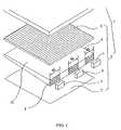
- FIG. 1is an exploded view illustrating the LCD of the first embodiment of the present invention in a schematic manner.
- the LCD 1has a liquid crystal panel 3 , an optical sheet 6 , and a backlight module 2 disposed under the liquid crystal panel 3 .
- the liquid crystal panel 3substantially comprises an upper substrate, a lower substrate (not shown), and a liquid crystal layer (not shown) disposed therebetween.
- the upper and lower substratescould respectively be a color filter substrate and an active array substrate.
- the backlight module 2further comprises a light guide plate 4 and at least one light source. It is preferable, as shown in the figure, to have a plurality of light sources.
- the plurality of light sourcescan be LEDs (light emit diodes) 5 .
- LEDslight emit diodes
- three LEDs 5are illustrated.
- the LEDs 5could be red, green, blue, white, or the combination thereof. It is understandable that the quantity, dimension, applied material, and colors of the LEDs 5 are not limited and could be freely adjusted according to the actual needs. Nevertheless, a preferred material of the light guide plate 4 is Poly (3-hydroxybutyrate-co-3-hydroxyvalerate) (PMMA).
- the light guide plate 4has an incidence face 8 and an emission face 12 (i.e. the end face which faces the users).
- the emission face 12is substantially perpendicular to the incidence face 8 .
- the incidence face 8has at least one incidence area 8 A and at least one surface 80 which formed along the incidence area 8 A.
- the embodiment as shownillustrates the plurality of surfaces 80 which are formed by a plurality of closed curves that form the three incidence areas 8 A.
- the surface 80could be formed by means of pressing or die casting.
- the surface 80could be integrated with the light guide plate 4 or attached onto the incidence area 8 A.
- the surfaces 80could be regularly or irregularly disposed onto the incidence area 8 A.
- the surfaces 80 of the present inventionare defined by a plurality of closed curves.
- each closed curvesis elliptical, circular, or another shape with endless contours.
- the surfaces 80should possess approximately 50% ⁇ 99% of the incidence area 8 A.
- the LEDs 5is disposed on the side of the incidence area 8 A for providing lights that are emitted onto the light guide plate 4 .
- the lightscould be uniformly emitted onto the liquid crystal panel 3 from the emission face 12 of the light guide plate 4 by being diffused at the surface 80 of the incidence area 8 A.
- an optical sheet 6should be disposed between the backlight module 2 and the liquid crystal panel 3 .
- the optical sheet 6could be a prism sheet, diffusion sheet, brightness enhancing sheet, or polarizing sheet. This optical sheet is used to enhance and uniform the lights provided by the backlight module 2 , or alter the polarization direction of the lights as desired. Therefore, the liquid crystal panel 3 would possess a better displaying quality.
- the LCD 1could further comprise a reflective sheet 7 disposed under the backlight module 2 for the lights provided from the LEDs 5 to reflect onto the light guide plate 4 .
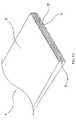
- FIG. 2is an exploded view illustrating another embodiment of the present invention.
- the light source of the present embodimentis an elongated light source covering the area where the whole incidence face 8 exists.
- the light sourceis commonly a cold cathode fluorescent lamp 9 , which is disposed adjacent to the side of the incidence face 8 of the light guide plate 4 , so that the whole incidence face 8 serves as the light incidence area 8 A.
- the formation and distribution of the surfaces 80 in this embodimentare similar to that of the former embodiment.
- FIG. 3 ais a schematic view illustrating the light guide plate 4 in FIG. 2 .
- the light guide plate 4includes the incidence face 8 and the emission face 12 that is substantially perpendicular to the incidence face 8 .
- the whole incidence face 8is a light incidence area which comprises the surfaces 80 defined by a plurality of closed curves 81 . In this embodiment, theses surfaces 80 possess 50% ⁇ 90% of the incidence face 8 .
- FIG. 3 bis a cross-sectional view showing the configuration of the incidence area 8 A of the light guide plate 4 .
- the light guide plate 4has the incidence face 8 and the emission face 12 .
- the incidence face 8comprises a plurality of surfaces 80 which are convex surfaces formed by at least one annular protrusion. The configurations, distribution densities, distributing and forming manners are disclosed in the description relating to FIG. 1 to FIG. 3 a.
- FIG. 3 cis a cross-sectional view illustrating another embodiment in view of FIG. 3 b .
- the light guide plate 4has the incidence face 8 and the emission face 12 .
- the incidence face 8comprises a plurality of surfaces 80 which are concave surfaces formed by at least one recess. The configurations, distribution densities, distributing and forming manners are disclosed in the description relating to FIG. 1 to FIG. 3 a.
Landscapes
- Physics & Mathematics (AREA)
- General Physics & Mathematics (AREA)
- Optics & Photonics (AREA)
- Planar Illumination Modules (AREA)
- Light Guides In General And Applications Therefor (AREA)
Abstract
Description
Claims (14)
Applications Claiming Priority (3)
| Application Number | Priority Date | Filing Date | Title |
|---|---|---|---|
| TW095108785ATW200734762A (en) | 2006-03-15 | 2006-03-15 | Light guide plate, and backlight module and liquid crystal display comprising the same |
| TW95108785 | 2006-03-15 | ||
| TW95108785A | 2006-03-15 |
Publications (2)
| Publication Number | Publication Date |
|---|---|
| US20070217224A1 US20070217224A1 (en) | 2007-09-20 |
| US8033709B2true US8033709B2 (en) | 2011-10-11 |
Family
ID=38517633
Family Applications (1)
| Application Number | Title | Priority Date | Filing Date |
|---|---|---|---|
| US11/461,801ActiveUS8033709B2 (en) | 2006-03-15 | 2006-08-02 | Light guide plate, and backlight module and liquid crystal display incorporating same |
Country Status (2)
| Country | Link |
|---|---|
| US (1) | US8033709B2 (en) |
| TW (1) | TW200734762A (en) |
Cited By (31)
| Publication number | Priority date | Publication date | Assignee | Title |
|---|---|---|---|---|
| US20080170173A1 (en)* | 2007-01-11 | 2008-07-17 | Samsung Electronics Co., Ltd. | Compact backlight assembly capable of adjusting light color level |
| US20130033893A1 (en)* | 2011-08-03 | 2013-02-07 | Japan Display East Inc. | Display device |
| USD681262S1 (en)* | 2012-07-24 | 2013-04-30 | Sang Chul Lee | Light guide plate |
| US20150009709A1 (en)* | 2012-02-29 | 2015-01-08 | Kolon Industries, Inc. | Light guide plate and backlight unit |
| US9223138B2 (en) | 2011-12-23 | 2015-12-29 | Microsoft Technology Licensing, Llc | Pixel opacity for augmented reality |
| US9297996B2 (en) | 2012-02-15 | 2016-03-29 | Microsoft Technology Licensing, Llc | Laser illumination scanning |
| US9304235B2 (en) | 2014-07-30 | 2016-04-05 | Microsoft Technology Licensing, Llc | Microfabrication |
| US9368546B2 (en) | 2012-02-15 | 2016-06-14 | Microsoft Technology Licensing, Llc | Imaging structure with embedded light sources |
| US9372347B1 (en) | 2015-02-09 | 2016-06-21 | Microsoft Technology Licensing, Llc | Display system |
| US9423360B1 (en) | 2015-02-09 | 2016-08-23 | Microsoft Technology Licensing, Llc | Optical components |
| US9429692B1 (en) | 2015-02-09 | 2016-08-30 | Microsoft Technology Licensing, Llc | Optical components |
| US9513480B2 (en) | 2015-02-09 | 2016-12-06 | Microsoft Technology Licensing, Llc | Waveguide |
| US9535253B2 (en) | 2015-02-09 | 2017-01-03 | Microsoft Technology Licensing, Llc | Display system |
| US9558590B2 (en) | 2012-03-28 | 2017-01-31 | Microsoft Technology Licensing, Llc | Augmented reality light guide display |
| US9578318B2 (en) | 2012-03-14 | 2017-02-21 | Microsoft Technology Licensing, Llc | Imaging structure emitter calibration |
| US9581820B2 (en) | 2012-06-04 | 2017-02-28 | Microsoft Technology Licensing, Llc | Multiple waveguide imaging structure |
| US9606586B2 (en) | 2012-01-23 | 2017-03-28 | Microsoft Technology Licensing, Llc | Heat transfer device |
| US9717981B2 (en) | 2012-04-05 | 2017-08-01 | Microsoft Technology Licensing, Llc | Augmented reality and physical games |
| US9726887B2 (en) | 2012-02-15 | 2017-08-08 | Microsoft Technology Licensing, Llc | Imaging structure color conversion |
| US9779643B2 (en) | 2012-02-15 | 2017-10-03 | Microsoft Technology Licensing, Llc | Imaging structure emitter configurations |
| US9827209B2 (en) | 2015-02-09 | 2017-11-28 | Microsoft Technology Licensing, Llc | Display system |
| US10018844B2 (en) | 2015-02-09 | 2018-07-10 | Microsoft Technology Licensing, Llc | Wearable image display system |
| US10191515B2 (en) | 2012-03-28 | 2019-01-29 | Microsoft Technology Licensing, Llc | Mobile device light guide display |
| US10192358B2 (en) | 2012-12-20 | 2019-01-29 | Microsoft Technology Licensing, Llc | Auto-stereoscopic augmented reality display |
| US10254942B2 (en) | 2014-07-31 | 2019-04-09 | Microsoft Technology Licensing, Llc | Adaptive sizing and positioning of application windows |
| US10317677B2 (en) | 2015-02-09 | 2019-06-11 | Microsoft Technology Licensing, Llc | Display system |
| US10502876B2 (en) | 2012-05-22 | 2019-12-10 | Microsoft Technology Licensing, Llc | Waveguide optics focus elements |
| US10592080B2 (en) | 2014-07-31 | 2020-03-17 | Microsoft Technology Licensing, Llc | Assisted presentation of application windows |
| US10678412B2 (en) | 2014-07-31 | 2020-06-09 | Microsoft Technology Licensing, Llc | Dynamic joint dividers for application windows |
| US11068049B2 (en) | 2012-03-23 | 2021-07-20 | Microsoft Technology Licensing, Llc | Light guide display and field of view |
| US11086216B2 (en) | 2015-02-09 | 2021-08-10 | Microsoft Technology Licensing, Llc | Generating electronic components |
Families Citing this family (20)
| Publication number | Priority date | Publication date | Assignee | Title |
|---|---|---|---|---|
| TW200728855A (en)* | 2006-01-23 | 2007-08-01 | Au Optronics Corp | Backlight structure |
| TWI482995B (en)* | 2009-07-20 | 2015-05-01 | Ind Tech Res Inst | Light collecting device and lighting equipment |
| TWI405008B (en)* | 2009-12-04 | 2013-08-11 | Au Optronics Corp | Backlight module and display device having the same |
| US20120120080A1 (en)* | 2010-11-16 | 2012-05-17 | Qualcomm Mems Technologies, Inc. | Light guide with diffusive light input interface |
| KR20120088121A (en)* | 2011-01-31 | 2012-08-08 | 삼성전자주식회사 | Backlight assembly and display apparatus having the same |
| US9201185B2 (en)* | 2011-02-04 | 2015-12-01 | Microsoft Technology Licensing, Llc | Directional backlighting for display panels |
| TWI448737B (en)* | 2011-09-14 | 2014-08-11 | Entire Technology Co Ltd | Optical strip and backlight module and lcd device having the optical strip |
| US9354748B2 (en) | 2012-02-13 | 2016-05-31 | Microsoft Technology Licensing, Llc | Optical stylus interaction |
| US9460029B2 (en) | 2012-03-02 | 2016-10-04 | Microsoft Technology Licensing, Llc | Pressure sensitive keys |
| US9075566B2 (en) | 2012-03-02 | 2015-07-07 | Microsoft Technoogy Licensing, LLC | Flexible hinge spine |
| US9870066B2 (en) | 2012-03-02 | 2018-01-16 | Microsoft Technology Licensing, Llc | Method of manufacturing an input device |
| US20130300590A1 (en) | 2012-05-14 | 2013-11-14 | Paul Henry Dietz | Audio Feedback |
| US8947353B2 (en) | 2012-06-12 | 2015-02-03 | Microsoft Corporation | Photosensor array gesture detection |
| US9256089B2 (en) | 2012-06-15 | 2016-02-09 | Microsoft Technology Licensing, Llc | Object-detecting backlight unit |
| US8964379B2 (en) | 2012-08-20 | 2015-02-24 | Microsoft Corporation | Switchable magnetic lock |
| CN104459867A (en)* | 2013-09-23 | 2015-03-25 | 纬创资通股份有限公司 | Light guide plate and backlight module |
| CN104597553B (en)* | 2013-10-30 | 2017-09-12 | 纬创资通股份有限公司 | Light guide plate |
| CN105278028A (en)* | 2014-06-20 | 2016-01-27 | 群创光电股份有限公司 | Light guide plate and display device using the light guide plate |
| EP3295226A1 (en)* | 2015-05-13 | 2018-03-21 | Corning Incorporated | Light guides with reduced hot spots and methods for making the same |
| CN108663743B (en)* | 2018-05-21 | 2019-08-02 | 京东方科技集团股份有限公司 | Backlight module and display device |
Citations (8)
| Publication number | Priority date | Publication date | Assignee | Title |
|---|---|---|---|---|
| US6065845A (en)* | 1997-03-18 | 2000-05-23 | Seiko Epson Corporation | Lighting device, liquid crystal display device and electronic equipment |
| US6435686B1 (en)* | 1999-02-26 | 2002-08-20 | The Ohtsu Tire & Rubber Co., Ltd. | Light conducting plate for a back lighting device and back lighting device |
| US20030076669A1 (en)* | 2001-10-22 | 2003-04-24 | Kabushiki Kaisha Advanced Display | Surface light source device and liquid crystal display device using it |
| US6601962B1 (en)* | 1999-05-11 | 2003-08-05 | Nichia Corporation | Surface light emitting device |
| CN1601353A (en) | 2003-09-23 | 2005-03-30 | 统宝光电股份有限公司 | Backlight module for flat panel display |
| US20050185915A1 (en)* | 2004-02-19 | 2005-08-25 | Hon Hai Precision Industry Co., Ltd. | Light guide plate with subwavelength grating and backlight module using the same |
| US7011440B2 (en)* | 2002-12-20 | 2006-03-14 | Hon Hai Precision Ind. Co., Ltd. | Planar surface illuminator |
| US20060072339A1 (en)* | 2004-10-01 | 2006-04-06 | Hsiao-I Li | Backlight module |
- 2006
- 2006-03-15TWTW095108785Apatent/TW200734762A/enunknown
- 2006-08-02USUS11/461,801patent/US8033709B2/enactiveActive
Patent Citations (8)
| Publication number | Priority date | Publication date | Assignee | Title |
|---|---|---|---|---|
| US6065845A (en)* | 1997-03-18 | 2000-05-23 | Seiko Epson Corporation | Lighting device, liquid crystal display device and electronic equipment |
| US6435686B1 (en)* | 1999-02-26 | 2002-08-20 | The Ohtsu Tire & Rubber Co., Ltd. | Light conducting plate for a back lighting device and back lighting device |
| US6601962B1 (en)* | 1999-05-11 | 2003-08-05 | Nichia Corporation | Surface light emitting device |
| US20030076669A1 (en)* | 2001-10-22 | 2003-04-24 | Kabushiki Kaisha Advanced Display | Surface light source device and liquid crystal display device using it |
| US7011440B2 (en)* | 2002-12-20 | 2006-03-14 | Hon Hai Precision Ind. Co., Ltd. | Planar surface illuminator |
| CN1601353A (en) | 2003-09-23 | 2005-03-30 | 统宝光电股份有限公司 | Backlight module for flat panel display |
| US20050185915A1 (en)* | 2004-02-19 | 2005-08-25 | Hon Hai Precision Industry Co., Ltd. | Light guide plate with subwavelength grating and backlight module using the same |
| US20060072339A1 (en)* | 2004-10-01 | 2006-04-06 | Hsiao-I Li | Backlight module |
Non-Patent Citations (5)
| Title |
|---|
| Chinese language office action dated Dec. 22, 2009. |
| English language translation of abstract and pertinent parts of TW 200636355. |
| English language translation of abstract and pertinent parts of TW M282191. |
| English language translation of abstract of TW 2005535506. |
| English language translation of relevant parts of CN 1601353. |
Cited By (37)
| Publication number | Priority date | Publication date | Assignee | Title |
|---|---|---|---|---|
| US8197112B2 (en)* | 2007-01-11 | 2012-06-12 | Samsung Electronics Co., Ltd. | Backlight assembly having color level sensor |
| US20080170173A1 (en)* | 2007-01-11 | 2008-07-17 | Samsung Electronics Co., Ltd. | Compact backlight assembly capable of adjusting light color level |
| US20130033893A1 (en)* | 2011-08-03 | 2013-02-07 | Japan Display East Inc. | Display device |
| US8727594B2 (en)* | 2011-08-03 | 2014-05-20 | Japan Display Inc. | Display device |
| US9223138B2 (en) | 2011-12-23 | 2015-12-29 | Microsoft Technology Licensing, Llc | Pixel opacity for augmented reality |
| US9606586B2 (en) | 2012-01-23 | 2017-03-28 | Microsoft Technology Licensing, Llc | Heat transfer device |
| US9368546B2 (en) | 2012-02-15 | 2016-06-14 | Microsoft Technology Licensing, Llc | Imaging structure with embedded light sources |
| US9779643B2 (en) | 2012-02-15 | 2017-10-03 | Microsoft Technology Licensing, Llc | Imaging structure emitter configurations |
| US9726887B2 (en) | 2012-02-15 | 2017-08-08 | Microsoft Technology Licensing, Llc | Imaging structure color conversion |
| US9684174B2 (en) | 2012-02-15 | 2017-06-20 | Microsoft Technology Licensing, Llc | Imaging structure with embedded light sources |
| US9297996B2 (en) | 2012-02-15 | 2016-03-29 | Microsoft Technology Licensing, Llc | Laser illumination scanning |
| US20150009709A1 (en)* | 2012-02-29 | 2015-01-08 | Kolon Industries, Inc. | Light guide plate and backlight unit |
| US9578318B2 (en) | 2012-03-14 | 2017-02-21 | Microsoft Technology Licensing, Llc | Imaging structure emitter calibration |
| US9807381B2 (en) | 2012-03-14 | 2017-10-31 | Microsoft Technology Licensing, Llc | Imaging structure emitter calibration |
| US11068049B2 (en) | 2012-03-23 | 2021-07-20 | Microsoft Technology Licensing, Llc | Light guide display and field of view |
| US9558590B2 (en) | 2012-03-28 | 2017-01-31 | Microsoft Technology Licensing, Llc | Augmented reality light guide display |
| US10191515B2 (en) | 2012-03-28 | 2019-01-29 | Microsoft Technology Licensing, Llc | Mobile device light guide display |
| US10388073B2 (en) | 2012-03-28 | 2019-08-20 | Microsoft Technology Licensing, Llc | Augmented reality light guide display |
| US9717981B2 (en) | 2012-04-05 | 2017-08-01 | Microsoft Technology Licensing, Llc | Augmented reality and physical games |
| US10478717B2 (en) | 2012-04-05 | 2019-11-19 | Microsoft Technology Licensing, Llc | Augmented reality and physical games |
| US10502876B2 (en) | 2012-05-22 | 2019-12-10 | Microsoft Technology Licensing, Llc | Waveguide optics focus elements |
| US9581820B2 (en) | 2012-06-04 | 2017-02-28 | Microsoft Technology Licensing, Llc | Multiple waveguide imaging structure |
| USD681262S1 (en)* | 2012-07-24 | 2013-04-30 | Sang Chul Lee | Light guide plate |
| US10192358B2 (en) | 2012-12-20 | 2019-01-29 | Microsoft Technology Licensing, Llc | Auto-stereoscopic augmented reality display |
| US9304235B2 (en) | 2014-07-30 | 2016-04-05 | Microsoft Technology Licensing, Llc | Microfabrication |
| US10254942B2 (en) | 2014-07-31 | 2019-04-09 | Microsoft Technology Licensing, Llc | Adaptive sizing and positioning of application windows |
| US10592080B2 (en) | 2014-07-31 | 2020-03-17 | Microsoft Technology Licensing, Llc | Assisted presentation of application windows |
| US10678412B2 (en) | 2014-07-31 | 2020-06-09 | Microsoft Technology Licensing, Llc | Dynamic joint dividers for application windows |
| US10018844B2 (en) | 2015-02-09 | 2018-07-10 | Microsoft Technology Licensing, Llc | Wearable image display system |
| US9827209B2 (en) | 2015-02-09 | 2017-11-28 | Microsoft Technology Licensing, Llc | Display system |
| US9535253B2 (en) | 2015-02-09 | 2017-01-03 | Microsoft Technology Licensing, Llc | Display system |
| US10317677B2 (en) | 2015-02-09 | 2019-06-11 | Microsoft Technology Licensing, Llc | Display system |
| US9513480B2 (en) | 2015-02-09 | 2016-12-06 | Microsoft Technology Licensing, Llc | Waveguide |
| US9429692B1 (en) | 2015-02-09 | 2016-08-30 | Microsoft Technology Licensing, Llc | Optical components |
| US9423360B1 (en) | 2015-02-09 | 2016-08-23 | Microsoft Technology Licensing, Llc | Optical components |
| US9372347B1 (en) | 2015-02-09 | 2016-06-21 | Microsoft Technology Licensing, Llc | Display system |
| US11086216B2 (en) | 2015-02-09 | 2021-08-10 | Microsoft Technology Licensing, Llc | Generating electronic components |
Also Published As
| Publication number | Publication date |
|---|---|
| US20070217224A1 (en) | 2007-09-20 |
| TW200734762A (en) | 2007-09-16 |
Similar Documents
| Publication | Publication Date | Title |
|---|---|---|
| US8033709B2 (en) | Light guide plate, and backlight module and liquid crystal display incorporating same | |
| JP3923867B2 (en) | Planar light source device and liquid crystal display device using the same | |
| JP3931070B2 (en) | Planar light source device and liquid crystal display device including the same | |
| US7708428B2 (en) | Backlight assembly and display device having the same | |
| US7791683B2 (en) | Backlight systems for liquid crystal displays | |
| US7583018B2 (en) | Light source apparatus and display apparatus | |
| CN100399143C (en) | Backlight component | |
| US8339426B2 (en) | Illuminator and display having same | |
| US20060262564A1 (en) | Backlight and liquid crystal display device | |
| JP2006286906A (en) | Light emitting diode device, backlight device using the same, and liquid crystal display device | |
| JP2005347214A (en) | Planar light source device and display device using the same | |
| JP2005044661A (en) | Planar light source device and display device using the same | |
| KR20060050158A (en) | Surface light source device, lighting unit and beam control member | |
| CN101336350A (en) | Lighting device and liquid crystal display device | |
| JP2010097909A (en) | Backlight and liquid crystal display device | |
| US7125141B2 (en) | Apparatus for homogeneously distributing lights | |
| KR101408324B1 (en) | Led lens for wide diffusion light | |
| US20120063162A1 (en) | Illuminating Device and Liquid Crystal Display Device | |
| US7830474B2 (en) | Lighting device and liquid crystal display using it | |
| US9052543B2 (en) | Liquid crystal display | |
| US20070236929A1 (en) | Backlight module having reflection layer and liquid crystal display using same | |
| US7810979B2 (en) | Illuminating device with primary color LED and fluorescent light sources, and liquid crystal display device | |
| JP4760048B2 (en) | Backlight device and liquid crystal display device | |
| JP2005197072A (en) | Flat light source device | |
| US20080094539A1 (en) | Liquid crystal display with black/white liquid crystal display panel |
Legal Events
| Date | Code | Title | Description |
|---|---|---|---|
| AS | Assignment | Owner name:AU OPTRONICS CORP., TAIWAN Free format text:ASSIGNMENT OF ASSIGNORS INTEREST;ASSIGNORS:KAO, KO-CHIA;CHEN, CHIH-KUANG;REEL/FRAME:018042/0595 Effective date:20060720 | |
| STCF | Information on status: patent grant | Free format text:PATENTED CASE | |
| FPAY | Fee payment | Year of fee payment:4 | |
| MAFP | Maintenance fee payment | Free format text:PAYMENT OF MAINTENANCE FEE, 8TH YEAR, LARGE ENTITY (ORIGINAL EVENT CODE: M1552); ENTITY STATUS OF PATENT OWNER: LARGE ENTITY Year of fee payment:8 | |
| MAFP | Maintenance fee payment | Free format text:PAYMENT OF MAINTENANCE FEE, 12TH YEAR, LARGE ENTITY (ORIGINAL EVENT CODE: M1553); ENTITY STATUS OF PATENT OWNER: LARGE ENTITY Year of fee payment:12 | |
| AS | Assignment | Owner name:AUO CORPORATION, TAIWAN Free format text:CHANGE OF NAME;ASSIGNOR:AU OPTRONICS CORPORATION;REEL/FRAME:063785/0830 Effective date:20220718 | |
| AS | Assignment | Owner name:OPTRONIC SCIENCES LLC, TEXAS Free format text:ASSIGNMENT OF ASSIGNORS INTEREST;ASSIGNOR:AUO CORPORATION;REEL/FRAME:064658/0572 Effective date:20230802 |