US8032652B2 - Initiating peer-to-peer tunnels - Google Patents
Initiating peer-to-peer tunnelsDownload PDFInfo
- Publication number
- US8032652B2 US8032652B2US12/433,610US43361009AUS8032652B2US 8032652 B2US8032652 B2US 8032652B2US 43361009 AUS43361009 AUS 43361009AUS 8032652 B2US8032652 B2US 8032652B2
- Authority
- US
- United States
- Prior art keywords
- client
- peer
- traffic
- tunnel
- controller
- Prior art date
- Legal status (The legal status is an assumption and is not a legal conclusion. Google has not performed a legal analysis and makes no representation as to the accuracy of the status listed.)
- Active, expires
Links
- 230000000977initiatory effectEffects0.000titleabstractdescription4
- 238000000034methodMethods0.000claimsabstractdescription21
- 230000007704transitionEffects0.000claimsdescription6
- 230000003111delayed effectEffects0.000claims8
- 230000011664signalingEffects0.000claims6
- 230000008569processEffects0.000abstractdescription5
- 230000002457bidirectional effectEffects0.000abstractdescription3
- 230000000717retained effectEffects0.000abstractdescription2
- 238000013459approachMethods0.000description3
- 238000012544monitoring processMethods0.000description3
- 230000005540biological transmissionEffects0.000description2
- 230000000694effectsEffects0.000description2
- 238000007689inspectionMethods0.000description2
- 238000004377microelectronicMethods0.000description2
- 230000005641tunnelingEffects0.000description2
- 101150012579ADSL geneProteins0.000description1
- 102100020775Adenylosuccinate lyaseHuman genes0.000description1
- 108700040193Adenylosuccinate lyasesProteins0.000description1
- RYGMFSIKBFXOCR-UHFFFAOYSA-NCopperChemical compound[Cu]RYGMFSIKBFXOCR-UHFFFAOYSA-N0.000description1
- 241000700605VirusesSpecies0.000description1
- 230000004075alterationEffects0.000description1
- 230000015572biosynthetic processEffects0.000description1
- 229910052802copperInorganic materials0.000description1
- 239000010949copperSubstances0.000description1
- 230000001934delayEffects0.000description1
- 238000001514detection methodMethods0.000description1
- 238000001914filtrationMethods0.000description1
- 230000007246mechanismEffects0.000description1
- 230000004048modificationEffects0.000description1
- 238000012986modificationMethods0.000description1
- 239000013307optical fiberSubstances0.000description1
- 230000000737periodic effectEffects0.000description1
- 230000004044responseEffects0.000description1
Images


Classifications
- H—ELECTRICITY
- H04—ELECTRIC COMMUNICATION TECHNIQUE
- H04L—TRANSMISSION OF DIGITAL INFORMATION, e.g. TELEGRAPHIC COMMUNICATION
- H04L67/00—Network arrangements or protocols for supporting network services or applications
- H04L67/01—Protocols
- H04L67/10—Protocols in which an application is distributed across nodes in the network
- H04L67/104—Peer-to-peer [P2P] networks
- H04L67/1042—Peer-to-peer [P2P] networks using topology management mechanisms
- H—ELECTRICITY
- H04—ELECTRIC COMMUNICATION TECHNIQUE
- H04L—TRANSMISSION OF DIGITAL INFORMATION, e.g. TELEGRAPHIC COMMUNICATION
- H04L67/00—Network arrangements or protocols for supporting network services or applications
- H04L67/01—Protocols
- H04L67/10—Protocols in which an application is distributed across nodes in the network
- H04L67/104—Peer-to-peer [P2P] networks
- H04L67/1074—Peer-to-peer [P2P] networks for supporting data block transmission mechanisms
Definitions
- the present inventionrelates to digital networks, and in particular, to the problem of initiating traffic in peer-to-peer tunnels in switched digital systems.
- Modern digital networks operating under IEEE 803.2 and 802.11 standardsare called upon to support a wide range of wired and wireless clients.
- the transition of traffic from the slow pipe to the fast pipemay result in issues such as out-of-order arrival of packets, with fast pipe packets arriving at the destination before packets already in the slow pipe. While some applications may not be affected by such out-of-order arrival, other applications such as multimedia are affected, resulting in, for example, stuttered or dropped audio and/or video.
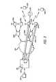
- FIG. 1shows a network
- FIG. 2shows details of network devices
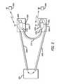
- FIG. 3shows tunnels in a network
- FIG. 4shows an additional network
- FIG. 5shows queued startup in a network.
- Embodiments of the inventionrelate to methods of initiating tunneling traffic in a digital network.
- a digital networkhas one or more central controllers to which a plurality of access nodes are connected.
- Each access nodeprovides a combination of wireless and/or wired access to resources available through the central controller.
- the access nodesmay be directly connected to the controller, or they may connect to the controller through routed networks such as a corporate Intranet, wider Internet, through private networks such as VPNs, or through a combination of wired and wireless backhaul.
- the access nodesestablish communications with the controller using tunnels.
- An example of a tunnelis a GRE tunnel. Traffic to and from clients connected to an access node is routed through the tunnel and through the central controller to which the access node is connected.
- a mobility controller processruns in the controller, monitoring traffic to and from clients.
- the set of access nodes known to the controller and other associated controllersis defined as the mobility domain.
- the mobility controllerWhen the mobility controller recognizes that traffic is being sent from a first client in the mobility domain to a second client in the mobility domain, the mobility controller evaluates whether the traffic is eligible for peer-to-peer forwarding. If the traffic is eligible for per-to-peer forwarding, the mobility manager instructs the access node to which the first client is connected to establish a peer-to-peer tunnel to the access node to which the second client is connected, and to direct the traffic through the peer-to-peer tunnel.
- traffic through the peer-to-peer tunnelmay begin flowing as soon as the peer-to-peer (“fast”) tunnel is established, or traffic in one or both directions through the tunnel may be queued until traffic flowing through the controller-terminated (“slow”) tunnels has completed.
- Completion of slow traffic through the controller-terminated tunnelsmay be sensed in a number of ways.
- Slow tunnel trafficmay be timed out, and queued traffic released after a preset time since the last packet was sent through the slow tunnel.
- the identity of the last packet sent through the slow tunnelmay be retained, and queued traffic released when an acknowledgement for that packet is received.
- a special packetmay be sent through the slow tunnel and queued traffic released when an acknowledgement for that packet is received.
- FIG. 1shows a digital network.
- Router 100connects to a network, not shown.
- Router 100also provides services to controller 200 .
- Controller 200has a plurality of ports, 230 a , 230 b for supporting devices such as access nodes 400 a , 400 b , 400 c , 400 d.
- these ports 120 a , 120 bconnect through switched network 290 to routers 300 a and 300 b.
- Access nodes 400 a , 400 b , 400 c , 400 dprovide wireless and possibly wired services to clients. As shown in FIG. 1 , wireless client 500 a is connected to access node 400 a . Access node 400 b supports wireless client 500 b and wired client 510 b . Access node supports wireless client 500 c.
- controllers 200are a purpose-built digital devices having a CPU 210 , memory hierarchy 220 , and a plurality of network interfaces 230 .
- CPU 210may be a MIPS-class processor from companies such as Raza Microelectronics or Cavium Networks, although CPUs from companies such as Intel, AMD, IBM, Freescale, or the like may also be used.
- Memory hierarchy 220includes read-only memory for device startup and initialization, high-speed read-write memory such as DRAM for containing programs and data during operation, and bulk memory such as hard disk or compact flash for permanent file storage of programs and data.
- Network interfaces 230are typically IEEE 802.3 Ethernet interfaces to copper, although high-speed optical fiber interfaces may also be used.
- Controller 200typically operates under the control of purpose-built embedded software, typically running under a Linux operating system, or an operating system for embedded devices such as VXWorks. Controller 200 may have dedicated hardware for encryption, and/or for routing packets between network interfaces 230 .
- access nodes 400 a , 400 b , 400 c and 400 dare also purpose-built digital devices. These access nodes include CPU 410 , memory hierarchy 420 , wired interface 430 , and wireless interface 440 . As with controller 200 , the CPU commonly used for such access nodes is a MIPS-class CPU such as one from Raza Microelectronics or Cavium Networks, although processors from other vendors such as Intel, AMD, Freescale, and IBM may be used.
- the memory hierarchycomprises read-only storage for device startup and initialization, fast read-write storage such as DRAM for holding operating programs and data, and permanent bulk file storage such as compact flash.
- Wireless access nodes 300typically operate under control of purpose-built programs running on an embedded operating system such as Linux or VXWorks.
- Wireless interface 340is typically an interface operating to the family of IEEE 802.11 standards including but not limited to 802.11a, b, g, and/or n.
- Multiple wired interfaces 430may be provided, with one wired interface 430 a being used to connect the access node to its controller, and the other wired interfaces 430 b used to host wired devices as clients. While wired interfaces such as 802.3 Ethernet may be used, USB may also be used to support printers, mass storage devices, and wireless back-haul links such as 3G or WiMAX modems.
- FIGS. 1 and 2depict a wired backhaul connecting access nodes 400 to controller 200
- a combination of wired and wireless backhaulsmay also be used, for example, using WiMAX, 3G, or other high-speed wireless connections.
- a wired connection to a modemsuch as an ADSL modem or a cable modem may be used, such a modem may also be built into access node 400 .
- Routers 300are also purpose-built digital devices, and similar to controller 200 , they contain a CPU, memory hierarchy, and a plurality of interfaces. Routers typically run dedicated software devoted to the tasks required. Routers are commercially available from a number of companies such as Cisco-Linksys, Hewlett Packard, D-Link, and others.
- Wireless clients 500are also digital devices, similarly having CPU 510 , memory hierarchy 520 , wireless interface 530 , and I/O devices 540 .
- wireless device 500may be a general purpose computer such as a laptop, or may be a purpose-built device such as a Wi-Fi phone or a handheld scanner.
- CPU 510may be a processor from companies such as Intel, AMD, Freescale, or the like.
- Acorn or MIPS class processorsmay be preferred.
- Memory hierarchy 520comprises the similar set of read-only memory for device startup and initialization, fast read-write memory for device operation and holding programs and data during execution, and permanent bulk file storage using devices such as flash, compact flash, and/or hard disks.
- Additional I/O devices 540may be present, such as keyboards, displays, speakers, barcode scanners, and the like.
- access nodes 400 a , 400 b , 400 c , 400 destablish communications with controller 200 , in the case of FIG. 3 , through routers 300 and switched network 200 .
- tunnels 600 a , 600 bsuch as GRE tunnels are established between the access node and controller 200 .
- Such tunnels 600 a , 600 bmay be established on a per-access node basis, or on a per network basis, with one tunnel established for each advertised wireless network (BSSD) or one tunnel established for each wired port on an access node.
- BSSDadvertised wireless network
- wireless client 500 ais connected to access node 400 a
- client 500 bis connected to access node 400 b
- traffic from client 500 apasses through access node 400 a , tunnel 600 a , to controller 200
- Controller 200identifies the traffic destination as client 500 b , and sends the traffic though tunnel 600 b to access node 400 b and client 500 b.
- This routingis performed by controller 200 using the IP addresses of clients 500 a and 500 b , as well as the MAC (media access controller) addresses of clients 500 a , 500 b and access nodes 400 a and 400 b .
- client 500 awishes to send data to client 500 b , it in essence forms an IP packet with client 500 b 's IP address as the destination, and with client 500 a 's IP address and MAC address as the source. This information is encapsulated and sent to controller 200 .
- Controller 200keeps tables of all access nodes it controls, and all clients associated with those nodes, including IP and MAC addresses. In this way, when it examines the packet from client 500 a , it can determine that client 500 b , the destination, is connected to access node 400 b , and direct the traffic through tunnel 600 b to that access point, and the destination device.
- controller 200Even if clients 500 a and 500 b are sitting in the same office suite, ten meters apart, traffic between them is routed through controller 200 .
- Mobility manager 280is a process running in controller 200 . By accessing controller 200 's tables of access nodes and their clients, mobility manager 280 can detect when a client is exchanging data with another client in its mobility domain.
- mobility manager 280when mobility manager 280 detects that client 500 a is communicating with client 500 b , also in the mobility domain of controller 200 , mobility manager 280 evaluates if this traffic is eligible for peer-to-peer forwarding. If the traffic is eligible for peer-to-peer forwarding, mobility manager 280 instructs access node 400 a to establish peer-to-peer tunnel 610 between access node 400 a and access 400 b , and to route that traffic between clients 500 a and 500 b through tunnel 610 rather than through tunnel 600 a . While the peer-to-peer tunnel is being established, traffic between clients flows through the controller. In this manner traffic between clients 500 a and 500 b rather than traveling through tunnels 600 a and 600 b and controller 200 , instead travels through tunnel 610 once the tunnel is established.
- a peer-to-peer tunnelmay be established any time mobility manager 280 detects connections and data exchanges between clients in its mobility domain. Or, peer-to-peer tunnels may be evaluated and only established on an authenticated basis according to pre-established rules. Peer-to-peer tunnels may be limited by client identity, including but not limited to client IP address, client MAC address, client authentication, and the like, destination identity, port, traffic type, and so on. As an example, assume a high-speed printer is connected as a client to access node 400 a . Appropriate rules for the establishment of peer-to-peer tunnels for a printer would be limited to ports and protocols needed for printer use for local authorized users, with no access allowed for guests.
- traffic to e-mail serverswould not be eligible for peer-to-per forwarding, so that such traffic would always pass through controller 280 and be subject to firewalling, virus detection, deep packet inspection, and the like.
- network time protocol traffic on port 123would be eligible for peer-to-peer forwarding to reduce transit delays for time data.
- Peer-to-peer tunnelsmay be established on a session basis, or may be aged. As an example, for a device such as a high-speed printer, a peer-to-peer tunnel with a timeout of thirty seconds may be appropriate; if no activity passes through the tunnel for that predetermined period of time, the tunnel is discontinued. If bursts of traffic between two clients exceed the time-out period, the peer-to-peer tunnel will be discontinued, but the next traffic between the clients, which will once more be routed through controller 200 , causes the peer-to-peer tunnel to be re-established.
- Peer-to-peer tunnelsmay be permitted for authorized users of the database for the specific protocols and ports used for database access, with all other traffic routed through controller 200 for filtering, firewalling, and authentication.
- database traffic using port 3306 between server 510 b and client 500 amay be routed through a peer-to-peer tunnel 610
- traffic on port 80 between client 500 a and server 510 bis still routed initially through controller 200 .
- mobility managers 280 operating in each controllermay cooperate in supporting peer-to-peer tunneling within the mobility domain.
- a mobility manager 280broadcasts updates of connected clients to other mobility managers in the mobility domain. These updates may be made on a periodic basis, may be event-driven, such as on client connection or disconnection, or on a combination.
- peer-to-peer forwardingmay be extended to cross controller boundaries.
- mobility managers 280may send queries to other mobility managers within the domain to inquire if a destination is a client of another mobility manager within the mobility domain. It may be useful in some embodiments to apply additional authentication when controller boundaries are crossed. As an example, consider an enterprise network spread over many locations, perhaps over many time zones. While establishing a peer-to-peer tunnel between a streaming media device such as a security webcam and a monitoring station offloads that streaming traffic from passing through the controller, other policies may wish to restrict access to such cameras to only users connected to the controller at the particular site, not allowing access across controller boundaries, or only allowing access across controller boundaries to certain classes of users.
- client 500 a of FIG. 4is receiving a video stream from a wireless camera 500 b .
- this trafficwill be routed through controller 200 via tunnels 600 b and 600 a .
- tunnel 610is established for this traffic between wireless camera 500 b and client 500 a.
- out-of-order deliverymay not be an issue.
- peer-to-peer tunnel trafficmay begin as soon as the tunnel is established, or traffic for the peer-to-peer tunnel may be queued until traffic has completed flowing through the controller-terminated “slow” tunnel.
- This queue and release modelmay be applied bidirectionally or unidirectionally.
- packets for the peer-to-peer tunnelare placed 460 in a queue 450 in the access node. This queue is released, and packets sent 470 through the peer-to-peer tunnel in a first-in-first-out fashion once traffic through the slow tunnel, in this example 600 b and 600 a , has completed.
- a special packetmay be sent through the slow tunnel; the queue is release when an ACK is received from the destination, indicating the special packet has arrived.
- the identification of the last packet sent through the slow tunnelmay be kept, and the queue released when an ACK is received from the destination indicating that this packet has arrived.
- a timermay be used, releasing the queue after a predetermined amount of time since the last packet was sent through the slow tunnel has elapsed.
- the value of this timermay be set by controller 200 , or it may be set by the access node.
- the access nodemay track the time the last packet was sent, and the time between sending a packet through the slow tunnel and the arrival of an ACK from the destination, and use a value based on such transit times.
- the timer approachprovides a useful backup mechanism in the event a marked packet is lost in transit.
- low-level responsessuch as ACKs are not queued, and once the peer-to-peer tunnel is established, these packets may be sent through the peer-to-peer tunnel, even if queueing is in effect.
- Such queueingmay be bidirectional, or unidirectional.
- a clientreceiving a video stream from a monitoring camera
- an essentially one-way flow of dataa unidirectional approach is adequate.
- bidirectional queuingis appropriate.
Landscapes
- Engineering & Computer Science (AREA)
- Computer Networks & Wireless Communication (AREA)
- Signal Processing (AREA)
- Business, Economics & Management (AREA)
- General Business, Economics & Management (AREA)
- Data Exchanges In Wide-Area Networks (AREA)
Abstract
Description
Claims (15)
Priority Applications (5)
| Application Number | Priority Date | Filing Date | Title |
|---|---|---|---|
| US12/433,610US8032652B2 (en) | 2009-04-30 | 2009-04-30 | Initiating peer-to-peer tunnels |
| US13/233,976US8788700B2 (en) | 2009-04-30 | 2011-09-15 | Initiating peer-to-peer tunnels |
| US14/293,352US9444888B2 (en) | 2009-04-24 | 2014-06-02 | Initiating peer-to-peer tunnels |
| US14/295,143US9456033B2 (en) | 2009-04-24 | 2014-06-03 | Initiating peer-to-peer tunnels |
| US15/267,856US20170013054A1 (en) | 2009-04-30 | 2016-09-16 | Initiating peer-to-peer tunnels |
Applications Claiming Priority (1)
| Application Number | Priority Date | Filing Date | Title |
|---|---|---|---|
| US12/433,610US8032652B2 (en) | 2009-04-30 | 2009-04-30 | Initiating peer-to-peer tunnels |
Related Parent Applications (1)
| Application Number | Title | Priority Date | Filing Date |
|---|---|---|---|
| US12/429,981ContinuationUS9049045B2 (en) | 2009-04-24 | 2009-04-24 | Peer-to-peer forwarding for packet-switched traffic |
Related Child Applications (3)
| Application Number | Title | Priority Date | Filing Date |
|---|---|---|---|
| US13/233,976ContinuationUS8788700B2 (en) | 2009-04-24 | 2011-09-15 | Initiating peer-to-peer tunnels |
| US14/293,352ContinuationUS9444888B2 (en) | 2009-04-24 | 2014-06-02 | Initiating peer-to-peer tunnels |
| US14/295,143ContinuationUS9456033B2 (en) | 2009-04-24 | 2014-06-03 | Initiating peer-to-peer tunnels |
Publications (2)
| Publication Number | Publication Date |
|---|---|
| US20100281180A1 US20100281180A1 (en) | 2010-11-04 |
| US8032652B2true US8032652B2 (en) | 2011-10-04 |
Family
ID=43031233
Family Applications (5)
| Application Number | Title | Priority Date | Filing Date |
|---|---|---|---|
| US12/433,610Active2029-09-07US8032652B2 (en) | 2009-04-24 | 2009-04-30 | Initiating peer-to-peer tunnels |
| US13/233,976ActiveUS8788700B2 (en) | 2009-04-24 | 2011-09-15 | Initiating peer-to-peer tunnels |
| US14/293,352ActiveUS9444888B2 (en) | 2009-04-24 | 2014-06-02 | Initiating peer-to-peer tunnels |
| US14/295,143Active2029-05-23US9456033B2 (en) | 2009-04-24 | 2014-06-03 | Initiating peer-to-peer tunnels |
| US15/267,856AbandonedUS20170013054A1 (en) | 2009-04-30 | 2016-09-16 | Initiating peer-to-peer tunnels |
Family Applications After (4)
| Application Number | Title | Priority Date | Filing Date |
|---|---|---|---|
| US13/233,976ActiveUS8788700B2 (en) | 2009-04-24 | 2011-09-15 | Initiating peer-to-peer tunnels |
| US14/293,352ActiveUS9444888B2 (en) | 2009-04-24 | 2014-06-02 | Initiating peer-to-peer tunnels |
| US14/295,143Active2029-05-23US9456033B2 (en) | 2009-04-24 | 2014-06-03 | Initiating peer-to-peer tunnels |
| US15/267,856AbandonedUS20170013054A1 (en) | 2009-04-30 | 2016-09-16 | Initiating peer-to-peer tunnels |
Country Status (1)
| Country | Link |
|---|---|
| US (5) | US8032652B2 (en) |
Cited By (3)
| Publication number | Priority date | Publication date | Assignee | Title |
|---|---|---|---|---|
| US20100275017A1 (en)* | 2009-04-24 | 2010-10-28 | Aruba Networks, Inc. | Peer-to-Peer Forwarding for Packet-Switched Traffic |
| US8788700B2 (en) | 2009-04-30 | 2014-07-22 | Aruba Networks, Inc. | Initiating peer-to-peer tunnels |
| US20160283928A1 (en)* | 2015-03-25 | 2016-09-29 | Intel Corporation | Secure transactions with connected peripherals |
Families Citing this family (7)
| Publication number | Priority date | Publication date | Assignee | Title |
|---|---|---|---|---|
| EP2070271A1 (en)* | 2006-09-28 | 2009-06-17 | Nxp B.V. | Improved process for transferring data in a dual transfer mode between a mobile network and mobile stations, and corresponding circuit mobility management entity |
| TWI429308B (en)* | 2011-02-14 | 2014-03-01 | Wistron Corp | Method and mobile communication system capable of establishing peer-to-peer transmission |
| US9207938B2 (en) | 2012-08-29 | 2015-12-08 | Hewlett-Packard Development Company, L.P. | Instruction forwarding based on predication criteria |
| US9880528B2 (en) | 2013-08-21 | 2018-01-30 | Medtronic Minimed, Inc. | Medical devices and related updating methods and systems |
| US9889257B2 (en)* | 2013-08-21 | 2018-02-13 | Medtronic Minimed, Inc. | Systems and methods for updating medical devices |
| US9516554B2 (en)* | 2014-07-23 | 2016-12-06 | Alcatel Lucent | Method of coordinating a path switch and network elements associated therewith |
| US10931477B2 (en)* | 2016-03-18 | 2021-02-23 | Plume Design, Inc. | Layer two network tunnels for Wi-Fi client bridging in a distributed Wi-Fi network |
Citations (3)
| Publication number | Priority date | Publication date | Assignee | Title |
|---|---|---|---|---|
| US20040185777A1 (en)* | 2003-02-28 | 2004-09-23 | Lucent Technologies Inc. | Portable wireless gateway |
| US20060190719A1 (en)* | 2004-07-23 | 2006-08-24 | Citrix Systems, Inc. | Systems and methods for communicating a lossy protocol via a lossless protocol using false acknowledgements |
| US20070064605A1 (en)* | 2005-09-02 | 2007-03-22 | Intel Corporation | Network load balancing apparatus, systems, and methods |
Family Cites Families (25)
| Publication number | Priority date | Publication date | Assignee | Title |
|---|---|---|---|---|
| US6076168A (en)* | 1997-10-03 | 2000-06-13 | International Business Machines Corporation | Simplified method of configuring internet protocol security tunnels |
| US6580704B1 (en)* | 1999-08-26 | 2003-06-17 | Nokia Corporation | Direct mode communication method between two mobile terminals in access point controlled wireless LAN systems |
| US7130921B2 (en) | 2002-03-15 | 2006-10-31 | International Business Machines Corporation | Centrally enhanced peer-to-peer resource sharing method and apparatus |
| USRE43127E1 (en)* | 2002-06-12 | 2012-01-24 | Intellectual Ventures I Llc | Event-based multichannel direct link |
| US7899932B2 (en) | 2003-01-15 | 2011-03-01 | Panasonic Corporation | Relayed network address translator (NAT) traversal |
| GB0402739D0 (en) | 2004-02-09 | 2004-03-10 | Saviso Group Ltd | Methods and apparatus for routing in a network |
| US7206859B2 (en) | 2004-02-18 | 2007-04-17 | Motorola, Inc. | Method for optimized local routing between mobile nodes |
| US7616613B2 (en) | 2004-05-05 | 2009-11-10 | Cisco Technology, Inc. | Internet protocol authentication in layer-3 multipoint tunneling for wireless access points |
| US7840217B2 (en)* | 2004-07-23 | 2010-11-23 | Cisco Technology, Inc. | Methods and apparatus for achieving route optimization and location privacy in an IPV6 network |
| US7639681B2 (en) | 2004-11-23 | 2009-12-29 | Microsoft Corporation | System and method for a distributed server for peer-to-peer networks |
| US7577125B2 (en)* | 2005-07-08 | 2009-08-18 | Microsoft Corporation | Direct wireless client to client communication |
| US8130759B2 (en) | 2005-07-29 | 2012-03-06 | Opnet Technologies, Inc. | Routing validation |
| US8077683B2 (en)* | 2005-11-03 | 2011-12-13 | Interdigital Technology Corporation | Method and system for performing peer-to-peer communication between stations within a basic service set |
| US8296437B2 (en)* | 2005-12-29 | 2012-10-23 | Logmein, Inc. | Server-mediated setup and maintenance of peer-to-peer client computer communications |
| EP1999871A2 (en) | 2006-03-10 | 2008-12-10 | Peerant Inc. | Peer to peer inbound contact center |
| WO2007120915A2 (en) | 2006-04-17 | 2007-10-25 | Starent Networks Corporation | System and method for traffic localization |
| US8499095B1 (en)* | 2006-05-25 | 2013-07-30 | Cisco Technology, Inc. | Methods and apparatus for providing shortcut switching for a virtual private network |
| US8144593B2 (en)* | 2006-11-17 | 2012-03-27 | Qualcomm Incorporated | Method and apparatus for efficient routing in communication networks |
| US7912063B2 (en) | 2007-05-21 | 2011-03-22 | Arrowspan, Inc. | Secure communications for wireless mesh network access points |
| US8085793B2 (en)* | 2007-09-24 | 2011-12-27 | Telefonaktiebolaget Lm Ericsson (Publ) | Traffic localization with proxy mobility |
| EP2250827B1 (en)* | 2008-02-04 | 2014-03-12 | Telefonaktiebolaget L M Ericsson (publ) | A method and an apparatus for providing route optimisation |
| US8040845B2 (en)* | 2008-09-12 | 2011-10-18 | Telefonaktiebolaget L M Ericsson (Publ) | Efficient routing between a mobile node and a correspondent node in a proxy mobile IP network |
| US8599843B2 (en)* | 2009-03-02 | 2013-12-03 | Futurewei Technologies, Inc. | Apparatus and method for route optimization for proxy mobile internet protocol version six local routing |
| US8032652B2 (en) | 2009-04-30 | 2011-10-04 | Aruba Networks, Inc. | Initiating peer-to-peer tunnels |
| US9049045B2 (en) | 2009-04-24 | 2015-06-02 | Aruba Networks, Inc. | Peer-to-peer forwarding for packet-switched traffic |
- 2009
- 2009-04-30USUS12/433,610patent/US8032652B2/enactiveActive
- 2011
- 2011-09-15USUS13/233,976patent/US8788700B2/enactiveActive
- 2014
- 2014-06-02USUS14/293,352patent/US9444888B2/enactiveActive
- 2014-06-03USUS14/295,143patent/US9456033B2/enactiveActive
- 2016
- 2016-09-16USUS15/267,856patent/US20170013054A1/ennot_activeAbandoned
Patent Citations (3)
| Publication number | Priority date | Publication date | Assignee | Title |
|---|---|---|---|---|
| US20040185777A1 (en)* | 2003-02-28 | 2004-09-23 | Lucent Technologies Inc. | Portable wireless gateway |
| US20060190719A1 (en)* | 2004-07-23 | 2006-08-24 | Citrix Systems, Inc. | Systems and methods for communicating a lossy protocol via a lossless protocol using false acknowledgements |
| US20070064605A1 (en)* | 2005-09-02 | 2007-03-22 | Intel Corporation | Network load balancing apparatus, systems, and methods |
Non-Patent Citations (4)
| Title |
|---|
| Dommety, Network Working Group Request for Comments: 2890, Category: Standards Track, "Key and Sequence No. Extensions to GRE", Sep. 2000, pp. 1-7. |
| Farinacci et al., Network Working Group Request for Comments: 2784, Category: Standards Track, "Generic Routing Encapsulation (GRE)", Mar. 2000, pp. 1-9. |
| Hanks, Li, Farinacci & Traina, Network Working Group Request for Comments: 1701, Category: Informational, "Generic Routing Encapsulation (GRE)", Oct. 1994, pp. 1-8. |
| Hanks, Li, Farinacci & Traina, Network Working Group Request for Comments: 1702, Category: Informational, "Generic Routing Encapsulation over IPv4 Networks", Oct. 1994, pp. 1-4. |
Cited By (7)
| Publication number | Priority date | Publication date | Assignee | Title |
|---|---|---|---|---|
| US20100275017A1 (en)* | 2009-04-24 | 2010-10-28 | Aruba Networks, Inc. | Peer-to-Peer Forwarding for Packet-Switched Traffic |
| US9049045B2 (en) | 2009-04-24 | 2015-06-02 | Aruba Networks, Inc. | Peer-to-peer forwarding for packet-switched traffic |
| US9444888B2 (en) | 2009-04-24 | 2016-09-13 | Aruba Networks, Inc. | Initiating peer-to-peer tunnels |
| US9456033B2 (en) | 2009-04-24 | 2016-09-27 | Aruba Networks, Inc. | Initiating peer-to-peer tunnels |
| US8788700B2 (en) | 2009-04-30 | 2014-07-22 | Aruba Networks, Inc. | Initiating peer-to-peer tunnels |
| US20160283928A1 (en)* | 2015-03-25 | 2016-09-29 | Intel Corporation | Secure transactions with connected peripherals |
| US10496974B2 (en)* | 2015-03-25 | 2019-12-03 | Intel Corporation | Secure transactions with connected peripherals |
Also Published As
| Publication number | Publication date |
|---|---|
| US8788700B2 (en) | 2014-07-22 |
| US20120072532A1 (en) | 2012-03-22 |
| US20100281180A1 (en) | 2010-11-04 |
| US20140289338A1 (en) | 2014-09-25 |
| US20140280733A1 (en) | 2014-09-18 |
| US9456033B2 (en) | 2016-09-27 |
| US20170013054A1 (en) | 2017-01-12 |
| US9444888B2 (en) | 2016-09-13 |
Similar Documents
| Publication | Publication Date | Title |
|---|---|---|
| US8032652B2 (en) | Initiating peer-to-peer tunnels | |
| US9049045B2 (en) | Peer-to-peer forwarding for packet-switched traffic | |
| US11258531B2 (en) | System and method for peak flow detection in a communication network | |
| US10305904B2 (en) | Facilitating secure network traffic by an application delivery controller | |
| US10530641B2 (en) | Uninterrupted flow processing by a software defined network (SDN) appliance despite a lost or disrupted connection with an SDN controller | |
| US8199761B2 (en) | Communications multiplexing with packet-communication networks | |
| US7995469B2 (en) | System and method for providing intelligent quality of service management in a system with a plurality of telecommunication connections | |
| EP2055052B1 (en) | Triggering bandwidth reservation and priority remarking | |
| US20160014126A1 (en) | Facilitating a Secure 3 Party Network Session by a Network Device | |
| CN101199187A (en) | System and method for optimization of communication between network nodes | |
| WO2008157087A2 (en) | Proxy-based malware scan | |
| US10652310B2 (en) | Secure remote computer network | |
| CN114363242A (en) | Dynamic multi-path optimization method, system and device based on cloud-network fusion technology | |
| CN114337939A (en) | Network system and network optimization method based on cloud-network integration technology | |
| CN114337931A (en) | Packet loss compensation method, system and equipment based on cloud network fusion technology | |
| US20170163422A1 (en) | Quality of service for web real-time communication networks | |
| US20170332423A9 (en) | Peer-to-Peer Forwarding for Packet-Switched Traffic | |
| JP2003338843A (en) | Routing apparatus and routing method | |
| CN105743925A (en) | Data transmission control method and video monitoring system | |
| US20140022888A1 (en) | Server Arbitrated Reliable Multicast System and a Process for Accessing the Same | |
| US8792823B2 (en) | Approach for quality of service control on un-wanted services (e.g. voice over internet protocol or multimedia) over wireline and wireless IP network | |
| US11956328B1 (en) | Avoiding stuck subscriber sessions on a disaggregated broadband network gateway | |
| CN212435737U (en) | A system for accessing network resources | |
| Vanparia et al. | Comparing Study of Transport Layer Protocols SCTP with TCP and UDP | |
| But et al. | ANGEL: architecture |
Legal Events
| Date | Code | Title | Description |
|---|---|---|---|
| AS | Assignment | Owner name:ARUBA NETWORKS, INC., CALIFORNIA Free format text:ASSIGNMENT OF ASSIGNORS INTEREST;ASSIGNOR:IYER, PRADEEP J.;REEL/FRAME:022623/0734 Effective date:20090429 | |
| STCF | Information on status: patent grant | Free format text:PATENTED CASE | |
| CC | Certificate of correction | ||
| FPAY | Fee payment | Year of fee payment:4 | |
| AS | Assignment | Owner name:HEWLETT-PACKARD DEVELOPMENT COMPANY, L.P., TEXAS Free format text:ASSIGNMENT OF ASSIGNORS INTEREST;ASSIGNOR:ARUBA NETWORKS, INC.;REEL/FRAME:035814/0518 Effective date:20150529 | |
| AS | Assignment | Owner name:ARUBA NETWORKS, INC., CALIFORNIA Free format text:ASSIGNMENT OF ASSIGNORS INTEREST;ASSIGNOR:HEWLETT-PACKARD DEVELOPMENT COMPANY, L.P.;REEL/FRAME:036379/0274 Effective date:20150807 | |
| AS | Assignment | Owner name:HEWLETT PACKARD ENTERPRISE DEVELOPMENT LP, TEXAS Free format text:ASSIGNMENT OF ASSIGNORS INTEREST;ASSIGNOR:ARUBA NETWORKS, INC.;REEL/FRAME:045921/0055 Effective date:20171115 | |
| MAFP | Maintenance fee payment | Free format text:PAYMENT OF MAINTENANCE FEE, 8TH YEAR, LARGE ENTITY (ORIGINAL EVENT CODE: M1552); ENTITY STATUS OF PATENT OWNER: LARGE ENTITY Year of fee payment:8 | |
| MAFP | Maintenance fee payment | Free format text:PAYMENT OF MAINTENANCE FEE, 12TH YEAR, LARGE ENTITY (ORIGINAL EVENT CODE: M1553); ENTITY STATUS OF PATENT OWNER: LARGE ENTITY Year of fee payment:12 |