US8032254B2 - Method and apparatus for configuring an HVAC controller - Google Patents
Method and apparatus for configuring an HVAC controllerDownload PDFInfo
- Publication number
- US8032254B2 US8032254B2US12/323,394US32339408AUS8032254B2US 8032254 B2US8032254 B2US 8032254B2US 32339408 AUS32339408 AUS 32339408AUS 8032254 B2US8032254 B2US 8032254B2
- Authority
- US
- United States
- Prior art keywords
- button
- screen
- hvac controller
- display
- controller
- Prior art date
- Legal status (The legal status is an assumption and is not a legal conclusion. Google has not performed a legal analysis and makes no representation as to the accuracy of the status listed.)
- Active, expires
Links
Images


Classifications
- F—MECHANICAL ENGINEERING; LIGHTING; HEATING; WEAPONS; BLASTING
- F24—HEATING; RANGES; VENTILATING
- F24F—AIR-CONDITIONING; AIR-HUMIDIFICATION; VENTILATION; USE OF AIR CURRENTS FOR SCREENING
- F24F11/00—Control or safety arrangements
- F24F11/30—Control or safety arrangements for purposes related to the operation of the system, e.g. for safety or monitoring
- F—MECHANICAL ENGINEERING; LIGHTING; HEATING; WEAPONS; BLASTING
- F24—HEATING; RANGES; VENTILATING
- F24F—AIR-CONDITIONING; AIR-HUMIDIFICATION; VENTILATION; USE OF AIR CURRENTS FOR SCREENING
- F24F11/00—Control or safety arrangements
- F24F11/62—Control or safety arrangements characterised by the type of control or by internal processing, e.g. using fuzzy logic, adaptive control or estimation of values
- G—PHYSICS
- G05—CONTROLLING; REGULATING
- G05B—CONTROL OR REGULATING SYSTEMS IN GENERAL; FUNCTIONAL ELEMENTS OF SUCH SYSTEMS; MONITORING OR TESTING ARRANGEMENTS FOR SUCH SYSTEMS OR ELEMENTS
- G05B13/00—Adaptive control systems, i.e. systems automatically adjusting themselves to have a performance which is optimum according to some preassigned criterion
- G05B13/02—Adaptive control systems, i.e. systems automatically adjusting themselves to have a performance which is optimum according to some preassigned criterion electric
- G—PHYSICS
- G05—CONTROLLING; REGULATING
- G05B—CONTROL OR REGULATING SYSTEMS IN GENERAL; FUNCTIONAL ELEMENTS OF SUCH SYSTEMS; MONITORING OR TESTING ARRANGEMENTS FOR SUCH SYSTEMS OR ELEMENTS
- G05B15/00—Systems controlled by a computer
- G05B15/02—Systems controlled by a computer electric
- G—PHYSICS
- G05—CONTROLLING; REGULATING
- G05D—SYSTEMS FOR CONTROLLING OR REGULATING NON-ELECTRIC VARIABLES
- G05D23/00—Control of temperature
- G05D23/19—Control of temperature characterised by the use of electric means
- G05D23/1902—Control of temperature characterised by the use of electric means characterised by the use of a variable reference value
- G—PHYSICS
- G05—CONTROLLING; REGULATING
- G05D—SYSTEMS FOR CONTROLLING OR REGULATING NON-ELECTRIC VARIABLES
- G05D23/00—Control of temperature
- G05D23/19—Control of temperature characterised by the use of electric means
- G05D23/1917—Control of temperature characterised by the use of electric means using digital means
- F—MECHANICAL ENGINEERING; LIGHTING; HEATING; WEAPONS; BLASTING
- F24—HEATING; RANGES; VENTILATING
- F24F—AIR-CONDITIONING; AIR-HUMIDIFICATION; VENTILATION; USE OF AIR CURRENTS FOR SCREENING
- F24F11/00—Control or safety arrangements
- F24F11/50—Control or safety arrangements characterised by user interfaces or communication
- F24F11/52—Indication arrangements, e.g. displays
- F—MECHANICAL ENGINEERING; LIGHTING; HEATING; WEAPONS; BLASTING
- F24—HEATING; RANGES; VENTILATING
- F24F—AIR-CONDITIONING; AIR-HUMIDIFICATION; VENTILATION; USE OF AIR CURRENTS FOR SCREENING
- F24F11/00—Control or safety arrangements
- F24F11/62—Control or safety arrangements characterised by the type of control or by internal processing, e.g. using fuzzy logic, adaptive control or estimation of values
- F24F11/63—Electronic processing
- F24F11/65—Electronic processing for selecting an operating mode
Definitions
- the disclosurerelates generally to HVAC controllers.
- HVACHeating, ventilation, and/or air conditioning
- Many HVAC controllersinclude a controller that activates and deactivates one or more HVAC components of the HVAC system to affect and control one or more environmental conditions within the building. These environmental conditions can include, but are not limited to, temperature, humidity, and/or ventilation.
- HVAC controllermay include, or have access to, one or more sensors, and may use parameters provided by the one or more sensors to control the one or more HVAC components to achieve desired programmed or set environmental conditions. Because of the increased complexity of such modern HVAC controllers, programming and/or operating such devices can be considered difficult and/or confusing, particularly for novice and/or non-technical users. Thus, there is a need for HVAC controllers that are more intuitive and user friendly to program and operate.
- HVAC controllersthat are configured to be more intuitive and user friendly to program and operate.
- the disclosurerelates to HVAC controllers that include a touch screen interface that provides greater flexibility in displaying information to the user and/or soliciting information from the user, although this is not required.
- FIG. 1is a schematic view of an illustrative but non-limiting HVAC controller
- FIG. 2is a front view of an illustrative but non-limiting HVAC controller
- FIGS. 3 through 17provide illustrative but non-limiting examples of home screens that may be displayed upon the HVAC controllers of FIGS. 1 and 2 ;
- FIGS. 18 through 46provide illustrative but non-limiting examples of screens pertaining to creating and/or editing a schedule using the HVAC controllers of FIGS. 1 and 2 ;
- FIGS. 47 through 53provide illustrative but non-limiting examples of screens pertaining to creating and/or editing a vacation schedule using the HVAC controllers of FIGS. 1 and 2 ;
- FIGS. 54 through 60provide illustrative but non-limiting examples of screens pertaining to changing and/or viewing humidification and dehumidification settings using the HVAC controllers of FIGS. 1 and 2 ;
- FIGS. 61 through 66provide illustrative but non-limiting examples of screens pertaining to changing and/or viewing ventilation settings using the HVAC controllers of FIGS. 1 and 2 ;
- FIGS. 67 through 69provide illustrative but non-limiting examples of screens pertaining to setting system information using the HVAC controllers of FIGS. 1 and 2 ;
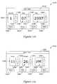
- FIGS. 70 through 72provide illustrative but non-limiting examples of screens pertaining to changing and/or viewing date and time settings using the HVAC controllers of FIGS. 1 and 2 ;
- FIGS. 73 through 95provide illustrative but non-limiting examples of screens pertaining to changing and/or viewing preferences information using the HVAC controllers of FIGS. 1 and 2 ;
- FIGS. 96 through 112provide illustrative but non-limiting examples of screens pertaining to temporary schedule changes using the HVAC controllers of FIGS. 1 and 2 ;
- FIGS. 113 through 114provide illustrative but non-limiting examples of screens pertaining to fan scheduling using the HVAC controllers of FIGS. 1 and 2 ;
- FIG. 115provides an illustrative but non-limiting example of a screen pertaining to locating a remote control using the HVAC controllers of FIGS. 1 and 2 ;
- FIGS. 116 through 117provide illustrative but non-limiting examples of screens pertaining to screen cleaning using the HVAC controllers of FIGS. 1 and 2 ;
- FIGS. 118 through 123provide illustrative but non-limiting examples of screens pertaining to changing and/or viewing security settings using the HVAC controllers of FIGS. 1 and 2 ;
- FIGS. 124 through 195provide illustrative but non-limiting examples of screens pertaining to installer setup of the HVAC controllers of FIGS. 1 and 2 .
- controllershaving programming capabilities. These controllers can be used in a variety of systems such as, for example, HVAC systems, water heater systems, water softener systems, sprinkler systems, security systems, lighting systems, and the like.
- HVACheating systems
- FIG. 1depicts HVAC controllers. While the present invention is not so limited, an appreciation of various aspects of the invention will be gained through a discussion of the examples provided below.
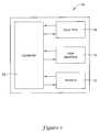
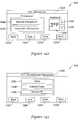
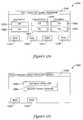
- FIG. 1is a schematic view of an illustrative HVAC controller 10 .
- HVAC controller 10may be considered to be a thermostat, but this is not required.
- HVAC controller 10includes a processor or controller 12 and a user interface 14 .
- Controller 12may be adapted to operate in accordance with an algorithm that controls or at least partially controls one or more components of an HVAC system.
- the algorithmmay include a number of operating parameters. Examples of components that may be controlled by controller 12 include one or more of a furnace, a boiler for hot water heat or steam heat, a heat pump, an air conditioning unit, a humidifier, a dehumidifier, an air exchanger, an air cleaner, and the like.
- Controller 12may, for example, operate in accordance with an algorithm that provides temperature set points, starting and/or ending times, and the like.
- User interface 14may be any suitable interface that permits controller 12 to display and/or solicit information as well as permitting a user to enter data such as temperature set points, humidity set points, starting times, ending times, and the like.
- user interface 14may include a display and a distinct keypad.
- a displaymay be any suitable alphanumeric display.
- a displaymay include or may be a liquid crystal display (LCD).
- user interface 14may be a touch screen LCD panel that functions as both display and keypad.
- a touch screen LCD panelmay be adapted to solicit values for a number of operating parameters and/or to receive said values.
- HVAC controller 10may include a memory block 16 that may be considered as being electrically connected to controller 12 .
- Memory block 16may be used to store any desired information, such as the aforementioned control algorithm, set points, and the like.
- Controller 12may store information within memory block 16 and may subsequently retrieved the stored information.
- Memory block 16may be any suitable type of storage device, such as RAM, ROM, EPROM, a flash drive, a hard drive, and the like.
- HVAC controller 10may include a data port 18 .
- Data port 18may be configured to communicate with controller 12 and may, if desired, be used to either upload information to controller 12 or to download information from controller 12 . Information that can be uploaded or downloaded may include values of operating parameters.
- data port 18may be used to upload a previously-created thermostat configuration into HVAC controller 10 , thereby hastening the programming process.
- data port 18may be used to download a thermostat configuration that has been created using HVAC controller 10 , so that the thermostat configuration may be used in other thermostats.
- data port 18may be used to upload and/or download information pertaining to an HVAC dealer or contractor.
- Data port 18may be a wireless port such as a BluetoothTM port or any other wireless protocol.
- data port 18may be a wired port such as a serial port, a parallel port, a CAT5 port, a USB (universal serial bus) port, or the like.
- data port 18may be a USB port and may be used to download and/or upload information from a USB flash drive. Other storage devices may also be employed, as desired.
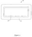
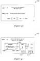
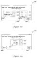
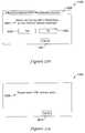
- FIG. 2is a front view of an illustrative HVAC controller 20 .
- HVAC controller 20may represent a manifestation of HVAC controller 10 ( FIG. 1 ), but this is not required.
- HVAC controller 20includes a display 22 that is disposed within a housing 24 .
- display 22may be a touch screen LCD display.
- display 22may be a dot matrix touch screen LCD display.
- a dot matrix touch screen LCD displayis a touch screen LCD that permits images such as letters, numbers, graphics, and the like to be displayed anywhere on the LCD, rather than being confined to predetermined locations such as is the case with a fixed segment LCD.
- Housing 24may be formed of any suitable material, such as a polymeric material.
- HVAC controller 20may be configured to provide substantial display and/or programming functionality.
- FIGS. 3 through 15provide examples of home screens that may be displayed by HVAC controller 20 .
- home screensmay include screens that can be accessed by a top level navigational menu.
- a home screenmay be a screen that is displayed by HVAC controller 20 as a default display, or when no other data entry is underway.
- a home screenmay, if desired, display one or more parameters relating to environmental conditions such as indoor and/or outdoor temperature and/or humidity, expected weather conditions, and/or the status of any equipment that is at least partially controlled by HVAC controller 20 .
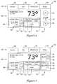
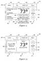
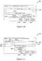
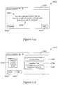
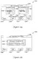
- HVAC controller 20is displaying on display 22 a home screen 24 that includes a navigational bar 26 that may be considered as providing top level navigation.
- navigation bar 26may include one or more of a HOME button 28 , a FAN button 30 , a HEAT/COOL button 32 and/or a MENU button 34 .
- the function of each button within navigational bar 26will be demonstrated, in turn.
- FIG. 3is an example of a screen that may be displayed after a user has pushed HOME button 28 .
- home screen 24may be considered as having two or more regions.
- home screen 24may include a first region 36 and a second region 38 .
- first region 36may be considered as displaying or otherwise providing primary information while second region 38 may be considered as displaying or otherwise providing secondary information.
- primary informationmay be information that is considered to be more important, more interesting and/or more useful than secondary information.
- first region 36may display one or more of a current temperature reading, a current indoor humidity, a schedule status, and the like.
- Second region 38may display one or more of a date and time, an outdoor temperature reading, an outdoor humidity reading, an equipment status, and the like.
- Home screen 24may also include a third region 40 that may be used for displaying and/or adjusting a parameter value such as a parameter that is displayed within first region 36 of home screen 24 .
- third region 40may include a parameter 42 , an up arrow 44 and a down arrow 46 .
- the value of parameter 42may be increased or decreased using, as necessary, up arrow 44 and/or down arrow 46 .
- second region 38may refer to a left-hand section of home screen 24
- third region 40may refer to a right-hand section of home screen 24
- first region 36may refer to a center section of home screen 24 that is between second region 38 and third region 40 .
- first region 36 , second region 38 and/or third region 40may instead be aligned vertically above or below the other regions within home screen 24 , as desired.
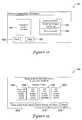
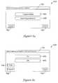
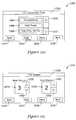
- HVAC controller 20is displaying on display 22 a home screen 48 that is similar in many ways to home screen 24 ( FIG. 3 ).
- Home screen 48includes a third region 50 that may be used to display and/or adjust two different parameter values.
- third region 50may, as illustrated, display both a heating temperature set point and a cooling temperature set point, but this is not required.
- Third region 50may include a first parameter 52 , a first up arrow 54 and a first down arrow 56 .
- Third region 50may include a second parameter 58 , a second up arrow 60 and a second down arrow 62 .
- First parameter 52may be adjusted up or down using first up arrow 54 and/or first down arrow 56 , as appropriate.
- Second parameter 58may be adjusted up or down using second up arrow 60 and/or second down arrow 62 , as desired.
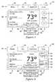
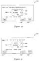
- pressing up arrow 44 and/or down arrow 46may cause HVAC controller 20 to display on display 22 a home screen 64 as shown in FIG. 5 .
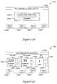
- Home screen 64may, as illustrated, include a hold bar 66 that is displayed along a portion of display 22 .
- Hold bar 66may include one or more of an adjustable time button 68 , a resume schedule button 70 , a permanent hold button 72 and a done button 74 .
- the adjustable time button 68may include an up arrow 76 and a down arrow 78 .
- a usermay adjust an ending time for a temperature hold by pressing up arrow 76 and/or down arrow 78 , as appropriate. If a user changes their mind, and wishes to instead return to the programmed schedule, they may do so simply by pressing resume schedule button 70 . Once they have adjusted the ending time as desired, they may press done button 74 .
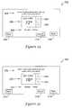
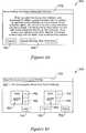
- FIG. 6is similar to FIG. 5 , but includes third region 50 as originally discussed with respect to FIG. 4 .
- FIG. 6shows a home screen 80 that might be displayed by HVAC controller if a user has pressed or one or more of first up arrow 54 , first down arrow 56 , second up arrow 60 and/or second down arrow 62 to adjust a temperature set point.
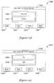
- HVAC controller 20may display on display 22 a home screen 82 , as shown in FIG. 7 .
- Home screen 82may include first region 36 , second region 38 and third region 40 as discussed with respect to FIG. 3 .
- first region 36may include a hold status button 84 that displays an ending time for the temporary temperature schedule as well as providing the user with a way to adjust the temporary temperature schedule.
- HVAC controller 22may instead display a permanent hold status button 86 in place of hold status button 84 .
- HVAC controller 20may permit a user to set a temporary temperature schedule that lasts longer than 24 hours and thus HVAC controller 20 may instead display a hold status button 88 in place of hold status button 84 or permanent hold status button 86 .
- FIG. 8is similar to FIG. 7 , but includes third region 50 as originally discussed with respect to FIG. 4 .
- FIG. 8shows a home screen 90 that might be displayed by HVAC controller if a user has pressed or one or more of first up arrow 54 , first down arrow 56 , second up arrow 60 and/or second down arrow 62 to adjust a temperature set point.
- FIG. 9shows an illustrative home screen 91 that in some ways is similar to home screen 82 ( FIG. 7 ), but accounts for HVAC controller 20 cooperating with a remote control.
- a remote controlis described in U.S. Provisional Patent Application No. 60/991,674 filed Nov. 30, 2007, entitled “REMOTE CONTROL UNIT FOR HVAC SYSTEM”, which application is hereby incorporated by reference herein.
- a remote controlmay be used to control one or more of a variety of different functions of HVAC controller 20 .
- HVAC controller 20may be configured to either sense ambient temperature at HVAC controller 20 using an internal thermal sensor and/or to use a temperature reading from a thermal sensor that may be present within the remote control.
- Home screen 91shows that HVAC controller 20 is using a temperature reading from the remote control, as indicated by the text “Sensing from remote” displayed within first region 36 of display 22 .
- An individualmay instead wish to instruct HVAC controller 20 to use the internal thermal sensor (or a remote sensor located near HVAC controller 20 and communicating wirelessly therewith).
- a Sense from Here button 93provides the individual with the opportunity to instruct HVAC controller 20 to use its internal thermal sensor.
- home screen 91may include a “Sense from Remote” button (not illustrated) and/or the remote control may include a button that permits the homeowner to instead sense the temperature from the remote.
- a Vacation button 95permits a homeowner to view and/or modify temporary vacation-related scheduling.
- HVAC controller 20may display a first image within first region 36 of display 22 and a second image within second region 38 .
- the first imagemay include a first set of information while the second image may include a second set of information.
- a third image that may include information pertaining to one or more HVAC system status conditionsmay temporarily replace the second image otherwise displayed within second region 38 .
- the first image, the second image and the third imagemay all be displayed on a home screen. In some cases, displaying the third image in place of the second image may not impact the display of the first image.
- the first set of information displayed within first region 36may include current indoor temperature, a temperature set point, an indoor humidity reading and schedule information.
- the second information displayed within second region 38may, for example, include one or more of date, a time, an equipment status and an outdoor weather parameter.
- HVAC controller 20may, for example, replace the second image with the first image when HVAC controller 30 detects the occurrence of one or more system status events or conditions.
- HVAC controller 20may provide messages such as informational messages, equipment status messages, and the like upon at least part of display 22 , particularly if home button 28 has been pressed or otherwise chosen or is automatically displayed after, for example, no user interaction is sensed for a period of time (e.g. thirty seconds).
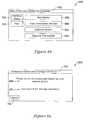
- FIG. 10provides an illustrative home screen 92 that includes an information button 94 . As illustrated, information button 94 may be displayed within second region 38 and as such does not interfere or otherwise eliminate any information displayed within first region 36 .
- Home screen 92includes third region 40 as discussed with respect to FIGS. 3 , 5 and 7 .
- FIG. 11provides a home screen 96 that includes information button 94 displayed within second region 38 , but includes third region 50 as discussed previously with respect to FIGS. 4 , 6 and 8 . In either case, pressing information button 94 may cause HVAC controller 20 to display further information pertaining to the shorter message displayed within information button 94 .
- Information button 94may provide a variety of equipment status messages. An example includes “Your air filter needs to be replaced.” Other examples may pertain to humidifier pad replacement, UV light replacement, and other furnace and/or A/C service schedules as appropriate, depending on installed equipment options.
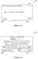
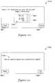
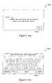
- FIGS. 10 and 11show information button 94 displaying the aforementioned message regarding air filter replacement. In some cases, pressing information button 94 (either in FIG. 10 or FIG. 11 ) will cause HVAC controller 20 to display a screen 100 , as shown in FIG. 12 .
- screen 100includes further information pertaining to the equipment status message included on information button 94 .
- Screen 100includes text 102 that provides the homeowner with information regarding what needs to be done and/or how to do it. As illustrated, text 102 says “Your system's (equipment name) (e.g. air filter) needs to be replaced. When you have replaced it, please press Reset.” HVAC controller 20 may fill in the appropriate equipment name, and sometimes provide the appropriate model number and/or appropriate information. The appropriate equipment name, model number and/or other information may reference a current value of a variable that is embedded within the information message, if desired.
- equipment namee.g. air filter
- Screen 100includes a Reset button 104 , which may be pressed once the appropriate equipment has in fact been replaced.
- home screen 100may include a Reminder button 106 that provides the homeowner with a period of time sufficient to address the particular issue.
- Reminder button 106may temporarily satisfy HVAC controller 20 for a period of time long enough for the homeowner to go to the store and buy the appropriate replacement item such as a new air filter, a new humidifier pad, or the like.
- home screen 100may also include a Dealer button 108 .
- the installermay, if desired and as will be discussed with respect to subsequent Figures, enter information identifying the HVAC contractor.
- Dealer button 108the homeowner may, for example, be provided with a telephone number or email address for the HVAC contractor and thus the homeowner may simply call the HVAC contractor either to order the appropriate replacement item and/or to request that the contractor resolve the issue by obtaining and installing the appropriate replacement item.
- HVAC controller 20may contact the contractor by email message, text message, or the like.
- the messagemay, for example, include appropriate part numbers or other diagnostic information so that the contractor can bring the appropriate parts and/or equipment.
- HVAC controller 20would have to be provided with telephone or other Internet access in order to provide this functionality.
- HVAC controller 20may have more than one message to display.
- information button 94may instead display a message such as “There are multiple messages.” or something to that effect.
- screen 100may include a scroll bar 110 or the like that provides information pertaining to how many messages are waiting as well as providing scroll buttons 112 and 114 so that the homeowner or HVAC contractor may scroll through the messages. If there is only one message to display, scroll bar 110 may not be displayed.
- HVAC controller 20may display a help button that, if pressed, may cause HVAC controller 20 to display one or more context sensitive help screens that may provide the user with information that is pertinent to one or more displayed operating parameters.
- the help screenmay temporarily replace whatever information was being displayed.
- the help screensif displayed, may include information pertaining to, for example, operating parameters such as circulating fan operation, system operation, scheduling, humidification and/or dehumidification settings, ventilation settings, maintenance reminders, equipment settings, and the like.
- the help screenmay include current values of one or more variables embedded within the help screen message, if desired.
- the information that is displayedmay be context sensitive or dependent upon the operating and/or programming steps that are currently being undertaken by the user.
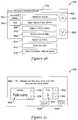
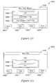
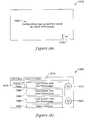
- FIG. 13provides an illustrative home screen 116 that may be displayed if Fan button 30 is pressed.
- a Help button 118may be displayed within second region 38 .
- the fan buttonsmay include, for example, one or more of a Run Continuously button 120 , an Automatic button 122 , an Intermittent button 124 and/or a Run Fan with Schedule button 126 .
- third region 40may include an up scroll button 128 and a down scroll button 130 in order to scroll through the available fan buttons.
- FIG. 14provides an illustrative help screen 132 that may be provided by HVAC controller 20 if a homeowner or other individual presses Help button 118 within home screen 116 ( FIG. 13 ).
- Second region 38may include a Back button 133 that permits an individual to return to the previous screen (e.g. FIG. 13 ) once they have read and understood the information provided within help screen 132 .
- First region 36includes textual information providing the individual with information pertaining to the fan choices presented within home screen 116 .
- Third region 40includes up scroll button 128 and down scroll button 130 in order to scroll up and down through the text provided within first region 36 , if necessary.
- FIG. 15provides an illustrative home screen 134 that may be displayed if Heat/Cool button 32 is pressed.
- a Help button 136may be displayed within second region 38 .
- the selection buttonsmay include, for example, one or more of a Heating button 138 , a Cooling button 140 , an Automatic button 142 , an Off button 144 and/or an Emergency Heat button 146 .
- third region 40may include an up scroll button 128 and a down scroll button 130 in order to scroll through the available selection buttons.
- FIG. 16provides an illustrative help screen 148 that may be provided by HVAC controller 20 if a homeowner or other individual presses Help button 136 within home screen 134 ( FIG. 15 ).
- Second region 38may include a Back button 133 that permits an individual to return to the previous screen (e.g. FIG. 15 ) once they have read and understood the information provided within help screen 132 .
- First region 36includes textual information providing the individual with information pertaining to the selection choices presented within home screen 116 .
- Third region 40includes up scroll button 128 and down scroll button 130 in order to scroll up and down through the displayed text.
- FIG. 17provides an illustrative home screen 150 that may be displayed if Menu button 34 is pressed.
- HVAC controller 20may display a variety of menu items within first region 36 and/or within second region 38 .
- Third region 40may include up scroll button 128 and down scroll button 130 to scroll up and down the displayed menu items, if necessary. These menu items may permit a homeowner or other individual to set a variety of parameters of HVAC controller 20 .
- home screen 150may include, for example, one or more of a Create/Edit Schedule button 152 , a Vacation Mode button 154 , an Humidification button 156 , a Dehumidification button 158 , a Ventilation button 160 , a System Information button 162 , a Date/Time button 164 , a Preferences button 166 , a Temporary Schedule Changes button 168 , a Schedule Fan button 170 , a Southern Dehumidification Mode button 172 , a Find Remote button 174 , a Clean Screen button 176 , a Security Settings button 178 and/or an Installer Set Up button 180 . Subsequent Figures will provide illustrative screens that may be displayed by HVAC controller 20 in response to a homeowner or other individual selecting one or more of these menu items.
- FIGS. 18 through 46provide illustrative but non-limiting examples of screens that may be displayed by HVAC controller 20 pertaining to creating, editing and/or viewing a schedule within HVAC controller 20 .
- FIG. 18provides an illustrative screen 182 that may be displayed by HVAC controller 20 in response to someone pressing or otherwise selecting Create/Edit Schedule button 152 ( FIG. 16 ).
- screen 182provides a user with one or more options as to how they wish to create, edit and/or view a schedule.
- Screen 182may include one or more of a View/Edit Current Schedule button 184 , a Guide Me Through The Scheduling button 186 and/or an I'll Do It Myself button 188 . The functionality of each will be described, in turn.
- Screen 182may include a Back button 190 that permits a user to return to a previous screen and/or a Help button 192 that may provide the user with pertinent assistance.
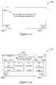
- pressing View/Edit Current Schedule button 184may cause HVAC controller 20 to display a screen 194 , as shown in FIG. 19 .
- Screen 194may display time and/or temperature set point information for one or more time periods of one or more days. As illustrated, screen 194 provides heating and cooling temperature set points for the Wake period, the Leave period, the Return period and the Sleep period for weekdays Monday through Friday. In some cases, screen 194 may be considered as including a Wake button 196 , a Leave button 198 , a Return button 200 and a Sleep button 202 .
- the heating and/or cooling temperature set points for a particular time periodmay be changed by pressing the appropriate button such as Wake button 196 , Leave button 198 , Return button 200 and/or Sleep button 202 .
- screen 194may include a View Individual Day button 204 that permits an individual to view only one day at a time, rather than a group of days. If View Individual Day button 204 is pressed, HVAC controller 20 may display heating and cooling temperature set points for one or more time periods for a single day, and may also display a button (not illustrated) that permits the user to scroll ahead to the next day.
- screen 194may include a Next Group of Days button 206 . If, for example, the displayed group of days is Monday-Friday, pressing Next Group of Days button 206 may cause HVAC controller 20 to display heating and cooling temperature set points for one or more periods of time for Saturday and/or Sunday.
- a Done button 208permits a user to tell HVAC controller 20 that they are done viewing and/or editing the schedule, and HVAC controller 20 may return to a previous screen, if desired.
- Screen 194may be considered a schedule review screen because the displayed schedule cannot be changed without touching one of buttons 196 - 202 . Once one of buttons 196 - 202 are touched, HVAC controller 20 may be considered to be in an edit mode. This may, for example, help the user to know whether changes are being made to the schedule.
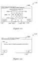
- FIG. 20provides an illustrative screen 210 that may be displayed by HVAC controller 20 if, with reference to screen 194 ( FIG. 19 ), one were to press Wake button 196 .
- Screen 210may permit a user to change one or more of a start time for the Wake time period, the cooling temperature set point and/or the heating temperature set point for Wake time period.
- Screen 210includes a Cancel This Period button 212 that, if pressed, permits the user to return to the previous screen and select a different time period, if desired.
- Screen 210includes a time setting block 214 that may include up and down buttons or other indicia that permit a user to alter the start time displayed within time setting block 214 .
- Screen 210may include a cooling temperature set point block 216 and/or a heating temperature set point block 218 .
- Each of cooling temperature set point block 216 and heating temperature set point block 218may include up and down button or other indicia that permit a user to alter the cooling temperature set point and/or the heating temperature set point.
- screen 210may include a Help button 220 that may, if pressed, cause HVAC controller 20 to display appropriate information pertaining to instructions, available options, and the like.
- a Cancel button 222may permit a user to cancel out of whatever changes they have entered, if any, without saving any changes.
- a Done button 224may be pressed to inform HVAC controller 20 that the changes, if any, have been entered and should be saved. In some cases, when Done button 224 is pressed, a message such as “Saving Changes” may be displayed, notifying the user that the changes are being saved.
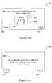
- FIG. 18another option for creating, editing and/or viewing a schedule is to press I'll Do It Myself button 188 . Pressing this button may cause HVAC controller 20 to display an illustrative screen 226 , shown in FIG. 21 .
- Screen 226includes a Monday button 228 , a Tuesday button 230 , a Wednesday button 232 , a Thursday button 234 , a Friday button 236 , a Saturday button 238 and a Sunday button 240 .
- One way to select which day or days to view/editis to press the button or buttons corresponding to the desired days. As illustrated, it can be seen that Monday button 228 , Tuesday button 230 , Wednesday button 232 , Thursday button 234 and Friday button 236 have been pressed.
- HVAC controller 20may, for example, display a first menu that includes one or more quick select touch buttons that may be used to quickly select two or more of a plurality of displayed selection options.
- each of the selection optionsmay have an associated algorithm parameter, and HVAC controller 20 may be configured to permit the user to simultaneously change the associated algorithm parameters for each of the two or more of the plurality of selection options that are selected by pressing one of the one or more quick select touch buttons.
- HVAC controller 20may display a second menu that permits the user to simultaneously change the associated algorithm parameters for each of the two or more of the plurality of selection options that are selected by pressing one of the one or more quick select touch buttons.
- HVAC controller 20may display a first menu that includes a schedule menu, and in this situation each of the plurality of selection options of the schedule menu may correspond to a corresponding day of a week.
- one of the quick select touch buttonsmay be a WEEKDAY button that, when pressed, selects Monday, Tuesday, Wednesday, Thursday and Friday for scheduling.
- WEEKEND buttonthat, when pressed, selects Saturday and Sunday for scheduling.
- ALL buttonthat, when pressed, selects all days of the week for scheduling.
- HVAC controller 20may display a schedule menu, and each of the plurality of selection options of the schedule menu may correspond to a PERIOD of a day of a week.
- one of the quick select touch buttonscomprises a wake button that, when pressed, selects the wake period for all or selected days of the week.
- one of the quick select touch buttonscomprises a leave button that, when pressed, selects the leave period for all or selected days of the week.
- one of the quick select touch buttonscomprises a return button that, when pressed, selects the return period for all or selected days of the week.
- one of the quick select touch buttonscomprises a sleep button that, when pressed, selects the sleep period for all or selected days of the week.
- a quick select buttonsuch as a Weekdays button 242 , a Weekends button 244 and/or an All button 246 .
- Pressing Weekdays button 242will cause all five week day buttons to be selected. As noted, Monday through Friday are indicated as having been selected. This may be achieved either by pressing each of the five day buttons or by simply pressing Weekdays button 242 . Pressing Weekends button 244 may cause Saturday button 238 and Sunday button 240 to be indicated as having been selected. Pressing All button 246 will cause all seven day buttons to be indicated as having been selected. Selected buttons may be indicated, for example, by graphically making each selected button to appear that it has been depressed. In some instances, selected buttons may be indicated in other ways, such as using bolded text, different colors and the like.
- HVAC controller 20may include text that helps the user to understand what is expected of them.
- screen 226can be seen to include the text “Select the days of the week to schedule”. Messages such as this may help the user navigate through the screens that may be displayed by HVAC controller 20 .
- Screen 226may include a Cancel button 248 and a Next button 250 .
- Cancel button 248may be pressed to cancel any changes that have been entered and cause HVAC controller 20 to revert to a previous screen.
- Next button 250may be pressed, for example, to move to the next screen.
- pressing Next button 250causes HVAC controller 20 to display an illustrative screen 252 , as shown in FIG. 22 .
- Screen 252includes a Wake button 254 , a Leave button 256 , a Return button 258 and a Sleep button 260 .
- a Back button 262permits a user to return to a previous screen such as screen 226 ( FIG. 21 ) to, for example, alter the day or days selected.
- HVAC controller 20may display text such as “Please press a time period below to schedule” to assist the user in navigation.
- Screen 264includes a time setting block 268 that may include up and down buttons or other indicia that permit a user to alter the start time displayed within time setting block 268 .
- Screen 264may include a cooling temperature set point block 270 and/or a heating temperature set point block 272 .
- Each of cooling temperature set point block 270 and heating temperature set point block 272may include up and down button or other indicia that permit a user to alter the cooling temperature set point and/or the heating temperature set point.
- screen 264may include a Help button 274 that may, if pressed, cause HVAC controller 20 to display appropriate information pertaining to instructions, available options, and the like.
- a Cancel button 276may permit a user to cancel out of whatever changes they have entered, if any, without saving any changes and/or return to a previous screen.
- a Next button 278may be pressed to indicate to HVAC controller 20 that the displayed time period has been edited as desired. If Next button 278 is pressed, HVAC controller 20 may display an illustrative screen 280 , as shown in FIG. 24 .
- Screen 280is similar to screen 252 ( FIG. 23 ), but includes the changes made to the Wake period made in FIG. 23 , and permits a user to select another time period to edit, if desired. However, screen 280 also includes a Done button 282 . If the use wishes to edit another time period, they may, one at a time, press one or more of Wake button 254 , Leave button 256 , Return button 258 and/or Sleep button 260 , and may edit the selected time period(s) as discussed with respect to FIG. 23 . However, once the user has finished editing the time periods they wish to edit, they may inform HVAC controller 20 that they have finished by pressing Done button 282 .
- HVAC controller 20may display an illustrative screen 284 , which is shown in FIG. 25 .
- HVAC controller 20may display a message informing the user that HVAC controller 20 is saving the changes that the user has made. HVAC controller may then display an illustrative screen 286 as shown in FIG. 26 .
- screen 286may include text asking the user if they wish to schedule other days.
- a Yes button 288 and a No button 290permits the user to provide their answer. If the user presses No button 290 , HVAC controller 20 may revert to screen 182 as seen in FIG. 18 . If the user presses Yes button 288 , HVAC controller 20 may revert to screen 226 as seen in FIG. 21 .
- the days already modifiedmay be indicated by displaying “modified” within the individual day buttons, but this is not required.
- HVAC controller 20may display an illustrative screen 292 , shown in FIG. 27 .
- Screen 292may be considered as an informational screen, as screen 292 provides a text message that informs the user that they will be asked a series of questions regarding their preferred comfort settings.
- a Back button 294permits a user to return to a previous screen, if desired, while a Next button 296 permits a user to advance to the next screen.
- HVAC controller 20will provide an illustrative screen 298 , as shown in FIG. 28 .
- Screen 298permits the user to select one or more days that will have the same schedule.
- Screen 298may include a text message to this effect.
- a usermay decide to have the same schedule for Monday through Friday and a different schedule for Saturday and Sunday.
- Screen 298includes a Monday button 300 , a Tuesday button 302 , a Wednesday button 304 , a Thursday button 306 , a Friday button 308 , a Saturday button 310 and a Sunday button 312 .
- Screen 298may include a Back button 314 that permits a user to return to a previous screen such as screen 292 ( FIG. 27 ), if desired, while a Cancel button 316 provides the user with an opportunity to revert to a previous screen or exit scheduling entirely.
- a Next button 318permits the user to advance to a subsequent screen. In some cases, pressing Next button 318 may cause HVAC controller 20 to display an illustrative screen 320 , as seen in FIG. 29 .
- Screen 320may be the result of having selected Monday, Tuesday, Wednesday, Thursday and Friday via screen 298 ( FIG. 28 ), as screen 320 includes a text message 322 that reminds the user which day or days have been selected. As shown, text message 322 simply says “Monday-Friday”. In some cases, it is considered that text message 322 may list each individual day by full name, by abbreviated name, and the like.
- Screen 320may include an interview question 324 , asking if someone is home during the day on the day or days being scheduled. The user may give an answer using either a Yes button 326 or a Not button 328 . If someone is home during the day, in some cases HVAC controller 20 may operate in accordance with a Wake time period and a Sleep time period, with the Leave and Return periods rolled into the Wake period or otherwise inactivated, for example. However, if no one is home during the day, HVAC controller 20 will in subsequent screens request scheduling and temperature information for all of the time periods.
- Screen 334may include an interview question 336 , asking what time the first person wakes up. HVAC controller 20 may, in some cases, use this time as the starting point for the Wake time period.
- Screen 334includes a time setting block 338 that displays the time period as well as a time at which the first person wakes up.
- Time setting block 338includes an Up arrow 340 and a Down arrow 342 that may be used to adjust the time as desired.
- Pressing Next button 318may cause HVAC controller 20 to display an illustrative screen 344 , as seen in FIG. 31 .
- Screen 344may include an interview question 346 , asking what time the last person leaves in the morning. HVAC controller 20 may, in some cases, use this time as the starting point for the Leave time period.
- Screen 344includes a time setting block 348 that displays the time period as well as a time at which the last person leaves.
- Time setting block 348includes an Up arrow 340 and a Down arrow 342 that may be used to adjust the time as desired.
- Pressing Next button 318may cause HVAC controller 20 to display an illustrative screen 350 , as seen in FIG. 32 .
- Screen 350may include an interview question 352 , asking what time the first person returns home. HVAC controller 20 may, in some cases, use this time as the starting point for the Return time period.
- Screen 350includes a time setting block 354 that displays the time period as well as a time at which the last person leaves.
- Time setting block 354includes an Up arrow 340 and a Down arrow 342 that may be used to adjust the time as desired.
- Pressing Next button 318may cause HVAC controller 20 to display an illustrative screen 356 , as seen in FIG. 33 .
- Screen 356may include an interview question 358 , asking what time the last person goes to sleep. HVAC controller 20 may, in some cases, use this time as the starting point for the Sleep time period.
- Screen 356includes a time setting block 360 that displays the time period as well as a time at which the last person goes to sleep.
- Time setting block 360includes an Up arrow 340 and a Down arrow 342 that may be used to adjust the time as desired.
- Pressing Next button 318may cause HVAC controller 20 to display an illustrative screen 362 , as seen in FIG. 34 .
- Screen 362may include an interview question 364 , asking what heating temperature is preferred when the user wakes up in the morning. HVAC controller 20 may, in some cases, use this temperature as the heating temperature set point for the Wake period.
- Screen 362includes a temperature setting block 366 that displays the time period, a heating temperature set point and an indication of which temperature set point is being set.
- Temperature setting block 366includes an Up arrow 340 and a Down arrow 342 that may be used to adjust the temperature as desired.
- Pressing Next button 318may cause HVAC controller 20 to display an illustrative screen 368 , as seen in FIG. 35 .
- Screen 368may include an interview question 370 , asking what cooling temperature is preferred when the user wakes up in the morning. HVAC controller 20 may, in some cases, use this temperature as the cooling temperature set point for the Wake period.
- Screen 368includes a temperature setting block 372 that displays the time period, a cooling temperature set point and an indication of which temperature set point is being set.
- Temperature setting block 372includes an Up arrow 340 and a Down arrow 342 that may be used to adjust the temperature as desired.
- Pressing Next button 318may cause HVAC controller 20 to display an illustrative screen 374 , as seen in FIG. 36 .
- Screen 374may include an interview question 376 , asking what heating temperature is preferred when the user is away from the house. HVAC controller 20 may, in some cases, use this temperature as the heating temperature set point for the Leave period.
- Screen 374includes a temperature setting block 378 that displays the time period, a heating temperature set point and an indication of which temperature set point is being set.
- Temperature setting block 378includes an Up arrow 340 and a Down arrow 342 that may be used to adjust the temperature as desired.
- screen 374may include a message 380 providing a suggested heating temperature set point.
- Pressing Next button 318may cause HVAC controller 20 to display an illustrative screen 382 , as seen in FIG. 37 .
- Screen 382may include an interview question 384 , asking what cooling temperature is preferred when the user is away from the house. HVAC controller 20 may, in some cases, use this temperature as the cooling temperature set point for the Leave period.
- Screen 382includes a temperature setting block 386 that displays the time period, a cooling temperature set point and an indication of which temperature set point is being set.
- Temperature setting block 386includes an Up arrow 340 and a Down arrow 342 that may be used to adjust the temperature as desired.
- screen 382may include a message 388 providing a suggested cooling temperature set point.
- Pressing Next button 318may cause HVAC controller 20 to display an illustrative screen 390 , as seen in FIG. 38 .
- Screen 390may include an interview question 392 , asking what heating temperature is preferred when the user returns home. HVAC controller 20 may, in some cases, use this temperature as the heating temperature set point for the Return period.
- Screen 390includes a temperature setting block 394 that displays the time period, a heating temperature set point and an indication of which temperature set point is being set.
- Temperature setting block 394includes an Up arrow 340 and a Down arrow 342 that may be used to adjust the temperature as desired.
- Pressing Next button 318may cause HVAC controller 20 to display an illustrative screen 396 , as seen in FIG. 39 .
- Screen 396may include an interview question 398 , asking what cooling temperature is preferred when the user returns home. HVAC controller 20 may, in some cases, use this temperature as the cooling temperature set point for the Return period.
- Screen 396includes a temperature setting block 400 that displays the time period, a cooling temperature set point and an indication of which temperature set point is being set.
- Temperature setting block 400includes an Up arrow 340 and a Down arrow 342 that may be used to adjust the temperature as desired.
- Pressing Next button 318may cause HVAC controller 20 to display an illustrative screen 402 , as seen in FIG. 40 .
- Screen 402may include an interview question 404 , asking what heating temperature is preferred when the user is sleeping. HVAC controller 20 may, in some cases, use this temperature as the heating temperature set point for the Sleep period.
- Screen 402includes a temperature setting block 406 that displays the time period, a heating temperature set point and an indication of which temperature set point is being set.
- Temperature setting block 406includes an Up arrow 340 and a Down arrow 342 that may be used to adjust the temperature as desired.
- Pressing Next button 318may cause HVAC controller 20 to display an illustrative screen 408 , as seen in FIG. 41 .
- Screen 408may include an interview question 410 , asking what cooling temperature is preferred when the user is sleeping. HVAC controller 20 may, in some cases, use this temperature as the cooling temperature set point for the Sleep period.
- Screen 408includes a temperature setting block 412 that displays the time period, a cooling temperature set point and an indication of which temperature set point is being set.
- Temperature setting block 412includes an Up arrow 340 and a Down arrow 342 that may be used to adjust the temperature as desired.
- Pressing Next button 318may cause HVAC controller 20 to display an illustrative screen 414 , as seen in FIG. 42 .
- Screen 414may include a question 416 , asking the user if they wish to schedule other days.
- a Yes button 418 and a No button 420permit the user to provide an appropriate answer. If the user presses Yes button 418 , HVAC controller 20 may revert to screen 298 ( FIG. 28 ) so that the user may select additional days to schedule. In some cases, although this is not required, the day buttons representing the days that have already been scheduled may be labeled as “modified”.
- HVAC controller 20may display an illustrative screen 422 , as seen in FIG. 43 .
- Screen 422may include a question 424 , inquiring as to whether or not the user wishes to review their schedule.
- a Yes button 426 and a No button 428permit the user to provide an appropriate answer. If the user presses No button 428 , HVAC controller 20 may revert to screen 182 ( FIG. 18 ). If the user presses Yes button 426 , HVAC controller 20 may display an illustrative screen 430 , as shown in FIG. 44 .
- Screen 430may include a message 432 instructing the user that they may, if desired, further edit their schedule by pressing one of the time periods.
- Screen 430may include a Wake button 434 , a Leave button 436 , a Return button 438 and a Sleep button 440 .
- Screen 430may include a View Individual Days button 442 that may, if pressed, instruct HVAC controller 20 to display only a single day at a time. Screen 430 may then include a Next Day button (not illustrated).
- a Next Group of Days button 444may, if pressed, instruct HVAC controller 20 to display another group of days. For example, HVAC controller 20 may display Saturday and Sunday.
- a Done button 446may, if pressed, inform HVAC controller 20 that the user is finished.
- Each of Wake button 434 , Leave button 436 , Return button 438 and Sleep button 440may include or otherwise display one or more of period starting time, period heating temperature set point and/or period cooling temperature set point. If the user wishes to edit one of the time periods, they may do so by pressing the desired time period button. For example, pressing Wake button 434 may cause HVAC controller 20 to display an illustrative screen 448 , as shown in FIG. 45 .
- Screen 448may include one or more of a time block 450 , a cooling temperature block 452 and/or a heating temperature block 454 .
- Time block 450may display a starting time for the Wake period, and may include Up arrow 340 and Down arrow 342 so that the user may adjust the starting time, if desired.
- Cooling temperature block 452may display a cooling temperature for the Wake period, and may include Up arrow 340 and Down arrow 342 so that the user may adjust the cooling temperature, if desired.
- Heating temperature block 454may display a heating temperature for the Wake period, and may include Up arrow 340 and Down arrow 342 so that the user may adjust the heating temperature, if desired.
- HVAC controller 20may display a similar screen in response to the user pressing (with respect to FIG. 44 ), any of Wake button 434 , Leave button 436 , Return button 438 and Sleep button 440 .
- screen 448may include text 456 informing the user that they have the opportunity to set the wake time and temperatures (or whichever time period is being displayed as a result of having pressed a particular time period button with respect to screen 430 , shown in FIG. 44 ).
- the usermay have the opportunity to simply delete the displayed time period by pressing a Delete Period button 458 .
- a Help button 460may be pressed to obtain additional information, selection options, and the like.
- FIG. 46provides an illustrative screen 462 that may be provided by HVAC controller 20 if, with respect to previous Figures, the user presses Cancel button 316 during some of the scheduling screens.
- Screen 462includes text 464 that informs the user that their changes will not be saved if they cancel.
- An inquiry 466asks the user to confirm if they wish to cancel, knowing that their changes will not be saved.
- a Yes button 468 and a No button 470permit a user to enter their preference.
- FIGS. 47 through 53provide illustrative but non-limiting examples of screens that may be displayed by HVAC controller 20 pertaining to creating, editing and/or viewing a vacation schedule within HVAC controller 20 .
- FIG. 47provides an illustrative screen 472 that may be displayed by HVAC controller 20 in response to someone pressing or otherwise selecting Vacation Mode button 154 ( FIG. 17 ).
- Screen 472may include text 474 that instructs the user to enter the date that they will be leaving on vacation.
- a Month block 476displays a month, and Up arrow 340 and/or Down arrow 342 may be used to scroll up and/or down to the desired month.
- a Date block 478displays a day of the month that can be adjusted up or down using Up arrow 340 and/or Down arrow 342 as desired. As illustrated, the date is displayed using numbers 1 through 31. In some cases, the corresponding day of the week (Monday, Tuesday, Wednesday, Thursday, Friday, Saturday and Sunday) may also be displayed, but this is not required.
- Cancel button 316may, if pressed, cause HVAC controller 20 to revert to screen 150 ( FIG. 17 ).
- Pressing Next button 318may cause HVAC controller 20 to display an illustrative screen 480 , as shown in FIG. 48 .
- Screen 40may include text 482 that instructs the user to set the time that they will be leaving on vacation.
- text 482may reference the date previously set with respect to screen 472 ( FIG. 47 ) but this is not required.
- a time block 484displays a departure time that can be adjusted using Up arrow 340 and/or Down arrow 342 , as appropriate.
- Back button 314permits the user to return to the previous screen, if, for example the date was set incorrectly.
- Pressing Next button 318may cause HVAC controller 20 to display an illustrative screen 486 , shown in FIG. 49 .
- screen 486may include text 488 instructing the user to enter a temperature that they want to maintain while they are on vacation.
- screen 486may include a cooling temperature block 490 displaying a cooling temperature set point and a heating temperature block 492 displaying a heating temperature set point. Cooling temperature block 490 and/or heating temperature block 492 may each independently include UP arrow 340 and Down arrow 342 for adjusting temperature settings as desired.
- screen 486may instead include only a single temperature block (not illustrated), particularly if the user does not take advantages of the programmability of HVAC controller 20 and instead simply uses HVAC controller 20 to hold a particular constant temperature, or if only a heating system or only a cooling system is included as part of the HVAC system.
- Back button 314permits the user to return to the previous screen, if desired.
- Pressing Next button 318may cause HVAC controller 20 to display an illustrative screen 494 , as shown in FIG. 50 .
- Screen 494may include text 496 that instructs the user to enter the date that they will be returning from vacation.
- a Month block 498displays a month, and Up arrow 340 and/or Down arrow 342 may be used to scroll up and/or down to the desired month.
- a Date block 500displays a day of the month that can be adjusted up or down using Up arrow 340 and/or Down arrow 342 as desired.
- Pressing Next button 318may cause HVAC controller 20 to display an illustrative screen 502 , as shown in FIG. 51 .
- Screen 502may include text 504 that instructs the user to set the time that they will be returning from vacation.
- text 504may reference the date previously set with respect to screen 486 ( FIG. 49 ) but this is not required.
- a time block 506displays a return time that can be adjusted using Up arrow 340 and/or Down arrow 342 , as appropriate.
- Back button 314permits the user to return to the previous screen, if, for example the date was set incorrectly.
- Pressing Next button 318may cause HVAC controller 20 to display an illustrative screen 508 , shown in FIG. 52 .
- screen 508may include text 510 instructing the user to enter a temperature that they want when they return from vacation.
- screen 508may include a cooling temperature block 512 displaying a cooling temperature set point and a heating temperature block 513 displaying a heating temperature set point. Cooling temperature block 512 and/or heating temperature block 513 may each independently include UP arrow 340 and Down arrow 342 for adjusting temperature settings as desired.
- screen 508may instead include only a single temperature block (not illustrated), particularly if the user does not take advantages of the programmability of HVAC controller 20 and instead simply uses HVAC controller 20 to hold a particular constant temperature, or if only a heating system or only a cooling system are included as part of the HVAC system.
- Back button 314permits the user to return to the previous screen, if desired.
- Pressing Next button 318may cause HVAC controller 20 to display an illustrative screen 514 , as shown in FIG. 53 .
- Screen 514may include text 516 that asks the user to confirm their vacation settings. If there is an error, or the user wishes to make any changes, they may do so by pressing Back button 314 and HVAC controller 20 will provide the appropriate screens to make any necessary changes. If the user agrees with the vacation settings, they may inform HVAC controller 20 thereof by pressing Yes button 520 .
- FIGS. 54 through 60provide illustrative but non-limiting examples of screens that may be displayed by HVAC controller 20 pertaining to changing and/or viewing humidification and dehumidification settings within HVAC controller 20 .
- FIGS. 54-57provide illustrative screens that may be displayed by HVAC controller 20 in response to someone pressing or otherwise selecting Humidification button 156 ( FIG. 17 )
- FIGS. 58-59provide illustrative screen that may be displayed by HVAC controller 20 in response to someone pressing or otherwise selecting Dehumidification button 158 ( FIG. 17 )
- FIG. 60provides an illustrative screen that may be displayed by HVAC controller 20 in response to someone pressing or otherwise selecting Southern Dehumidification Mode button 172 ( FIG. 17 ).
- FIG. 54provides an illustrative screen 522 that may include text 524 instructing the user to select or set their humidification setting.
- HVAC controller 20may, for example, use the humidification setting in controlling a humidifier such as a whole-house humidifier.
- HVAC controller 20may, for example, display a parameter adjustment element for use in adjusting an operating parameter such as humidification, the parameter adjustment element may include an indicator that provides a qualitative indication for at least the current setting of the operating parameter.
- screen 522includes a slider bar 526 that has a scale 528 , a display 530 , a Left arrow 532 and a Right arrow 534 .
- Scale 528can be seen as including text describing the humidification setting in relative or qualitative terms such as “Dry”, “Comfort Zone” and “Wet”. These particular terms are merely representative, as other terms may also be used. More generally, scale 528 may provide a qualitative context to a particular humidity value (e.g. 42%) so that a user unfamiliar with humidity values can still choose an appropriate humidity setting.
- Display 530may, as illustrated, provide a reminder that it is the indoor humidity setting that is being displayed as well as a current indoor humidity setting or current indoor humidity reading.
- FIG. 55provides an illustrative screen 536 having a display 538 that provides a display of the current indoor humidity setting or reading as well as an indication that frost protection has been activated, as will be discussed with respect to subsequent Figures.
- slider bar 526may be seen as including an indicator button 540 that may be moved left and/or right using left arrow 532 and/or right arrow 534 , as desired.
- Indicator button 540may, with respect to scale 528 , provide a visual indication of the relative or qualitative humidity setting and may, if desired, include a pointer that interacts with scale 528 .
- Scale 528may provide upper and/or lower numerical limits for the displayed parameter.
- indicator button 540may include a numerical representation of the indoor humidity setting.
- indicator button 540may move a prescribed distance either left or right in response to the user pressing either left arrow 532 or right arrow 534 . In some cases, the distance that indicator button 540 moves may be at least partially a function of how many times left arrow 532 and/or right arrow 534 are pressed. In some instances, the distance that indicator button 540 moves may be at least partially a function of how long left arrow 532 and/or right arrow 534 are held down by the user. In some cases, indicator button 540 may be a touch-sensitive button, and may be moved left or right simply by the user touching indicator button 540 and dragging their finger left or right.
- Screen 522may include a Disable Humidification button 542 .
- a usermay not wish to provide HVAC controller 20 with humidification settings. For example, in warm climates, the user may not want or need to operate a humidifier such as a whole-house humidifier that is controlled by HVAC controller 20 .
- a user's HVAC equipmentmay not include any humidification equipment. In situations such as these, the user may deactivate this functionality by pressing Disable Humidification button 542 .
- FIG. 56provides an illustrative screen 552 that is similar to screen 522 ( FIG. 54 ), but shows that HVAC controller 20 has grayed out slider bar 526 as a result of the user having pressed Disable Humidification button 542 . It can be seen that text 524 also states that humidification has been disabled.
- screen 552may include an Enable Humidification button 554 .
- screen 522may include a Window Frost Protection Setting button 544 , as will be discussed with respect to FIGS. 57 and 58 .
- a Help button 546may, if pressed, provide further information explaining humidification, providing clarification regarding options, and the like.
- a Cancel button 548if pressed, may cause HVAC controller 20 to revert to screen 150 ( FIG. 17 ) without saving any changes that may have been made.
- a Done button 550if pressed, informs HVAC controller 20 that the humidification setting has been completed, and as a result, may revert to screen 150 ( FIG. 17 ).
- Pressing Window Frost Protection Setting button 544may cause HVAC controller 20 to display an illustrative screen 556 , as shown in FIG. 57 .
- selecting an indoor humidification settingis similar to selecting a window frost protection setting, as the risk of window condensation, particularly in cold weather, is at least partially a function of the indoor air humidity.
- window condensationis also at least partially a function of the efficiency of the windows within the house or other building.
- HVAC controller 20may be in communication with an exterior temperature sensor and may be programmed to adjust humidity settings and/or window frost protection settings accordingly.
- Screen 556may include text 558 that informs the user that they are to select a setting for window frost protection.
- Screen 556includes a slider bar 560 that has a scale 562 , a display 564 , a left arrow 532 and a right arrow 534 .
- Scale 562may include text describing the window frost protection setting in relative or qualitative terms such as “Less Efficient” and “More Efficient”. It will be recognized that this refers to the relative efficiency of the windows within the building.
- Display 564may, as illustrated, provide a reminder that it is the window energy efficiency setting that is being displayed.
- Slider bar 560may be seen as including an indicator button 563 that may be moved left and/or right using left arrow 532 and/or right arrow 534 , as desired.
- Indicator button 563may, with respect to scale 562 , provide a visual indication of the relative or qualitative humidity setting and may, if desired, include a pointer that interacts with scale 562 .
- indicator button 563may include a numerical representation of the window frost protection setting.
- Indicator button 563may be moved using either left arrow 532 or right arrow 534 . In some cases, the distance that indicator button 563 moves may be at least partially a function of how many times or for how long left arrow 532 and/or right arrow 534 are pressed. In some cases, indicator button 563 may be a touch-sensitive button, and may be moved left or right simply by the user touching indicator button 563 and dragging their finger left or right.
- a Humidification Setting button 565may be pressed if the user wishes to return to screen 522 ( FIG. 54 ) to alter the humidification setting. Cancel button 548 , if pressed, may cause HVAC controller 20 to revert to screen 150 ( FIG. 17 ) without saving any changes that may have been made.
- Done button 550if pressed, informs HVAC controller 20 that the window frost protection setting has been completed, and as a result, may revert to screen 150 ( FIG. 17 ).
- FIG. 58shows an illustrative screen 566 that may include text 568 instructing the user to select or set their dehumidification setting.
- HVAC controller 20may, for example, use the dehumidification setting to control operation of a dehumidifier or an air exchanger.
- Screen 566includes a slider bar 570 that has a scale 572 , a display 574 , a Left arrow 532 and a Right arrow 534 .
- Scale 572can be seen as including text describing the dehumidification setting in relative or qualitative terms such as “Dry”, “Comfort Zone” and “Wet”. These particular terms are merely representative, as other terms may also be used. More generally, scale 572 may provide a qualitative context to a particular humidity value (e.g. 42%) so that a user unfamiliar with humidity values can still choose an appropriate dehumidification setting.
- a particular humidity valuee.g. 42%)
- Display 574may, as illustrated, provide the current indoor humidity setting or current indoor humidity reading.
- Slider bar 570may be seen as including an indicator button 576 that may be moved left and/or right using left arrow 532 and/or right arrow 534 , as desired.
- Indicator button 576may, with respect to scale 528 , provide a visual indication of the dehumidification setting and may, if desired, include a pointer that interacts with scale 574 .
- indicator button 576may include a numerical representation of the indoor humidity setting.
- Indicator button 576may be moved using either left arrow 532 or right arrow 534 . In some cases, the distance that indicator button 576 moves may be at least partially a function of how many times or for how long left arrow 532 and/or right arrow 534 are pressed. In some cases, indicator button 576 may be a touch-sensitive button, and may be moved left or right simply by the user touching indicator button 562 and dragging their finger left or right.
- Screen 566may, as illustrated, include a Disable Dehumidification button 578 .
- Pressing Disable Dehumidification button 578may cause HVAC controller 20 to display an illustrative screen 580 as shown in FIG. 59 . It can be seen that in screen 580 , slider bar 570 has been grayed out. Text 568 may also include a message reminding the user that dehumidification has been disabled. The user may wish to disable dehumidification if, for example, their HVAC equipment does not include a dehumidifier or an air exchanger.
- screen 580may include an Enable Dehumidification button 582 .
- cancel button 548if pressed, may cause HVAC controller 20 to revert to screen 150 ( FIG. 17 ) without saving any changes that may have been made.
- Done button 550if pressed, informs HVAC controller 20 that the dehumidification setting has been completed, and as a result, may revert to screen 150 ( FIG. 17 ).
- FIG. 60shows an illustrative screen 584 that may, for example, be reached by pressing Southern Dehumidification Mode button 172 ( FIG. 17 ).
- Screen 584provides the user with settings information pertaining to a southern dehumidification mode.
- Help button 546may provide educational or information messages pertaining to the southern dehumidification mode, and/or may discuss possible options.
- Cancel button 548if pressed, may cause HVAC controller 20 to revert to screen 150 ( FIG. 17 ).
- FIGS. 61 through 66provide illustrative but non-limiting examples of screens that may be displayed by HVAC controller 20 pertaining to changing and/or viewing ventilation settings within HVAC controller 20 . HVAC controller 20 may use these settings, for example, to control operation of an air exchanger or the like.
- FIG. 61provides an illustrative screen 586 that may be displayed by HVAC controller 20 in response to someone pressing or otherwise selecting Ventilation button 160 ( FIG. 16 ).
- Screen 586may include a menu bar 588 that includes navigational information so that the user may better remember and/or understand where they are within the menu and how they got there.
- Screen 586may include one or more of an Automatic button 590 , an On button 592 and an Off button 594 . If the user presses Automatic button 590 , HVAC controller 20 may operate the air exchanger only when, for example, other HVAC equipment such as a forced air furnace or an air conditioner is operating, or perhaps operate the air exchanger in accordance with dehumidification settings. Pressing On button 592 may cause HVAC controller 20 to operate the air exchanger at all times while pressing corresponding Off button 594 may cause HVAC controller 20 to not operate the air exchanger at all.
- screen 586may include a Temporary Override button 596 .
- a usermay want the air exchanger to run constantly for a relatively short period of time. Examples of when this may occur, for example, include a desire to eliminate strong cooking odors or perhaps steam from a hot shower. If the user presses Temporary Override button 596 , HVAC controller 20 may display an illustrative screen 598 , as shown in FIG. 62 .
- Time block 600includes a time block 600 that may be used to enter or edit a length of time for which the air exchanger will operate.
- Time block 600may include a numerical display 602 representing a length of time in any appropriate units such as minutes.
- Up arrow 604 and down arrow 606may be used, as desired, to increase or decrease the length of time for operating the air exchanger.
- a Cancel button 608may, if pressed, cause HVAC controller 20 to revert to a previous screen such as screen 150 ( FIG. 17 ).
- a Done button 610if pressed, tells HVAC controller 20 that a desired length of time has been entered, and thus HVAC controller 20 operates the air exchanger continuously for the specified length of time. In some cases, pressing Done button 610 also causes HVAC controller 20 to revert to screen 150 ( FIG. 17 ).
- screen 586includes Cancel button 608 and Done button 610 , as discussed with respect to FIG. 62 .
- Temporary Override button 596was pressed to bring up screen 598 ( FIG. 62 ), with screen 598 including time block 600 .
- time block 600may instead be displayed on the same screen as Automatic button 590 , On button 592 and Off button 594 , for example.
- FIG. 64provides an illustrative screen 614 that includes a Vent in All Periods button 616 and a Do Not Vent While Sleeping button 618 . If the user presses Vent in All Periods button 616 , they may be provided an opportunity to set ventilation settings for one or more of the aforementioned time periods. If they press Do Not Vent While Sleeping button 618 , they may be given the opportunity to set ventilation settings for one or more the aforementioned time periods absent the Sleep period. In some cases, other options such as a Do Not Vent while Gone button.
- a Help button 620may, if pressed, provide the user with more information pertaining to their options.
- pressing one of Vent in All Periods button 616 or Do Not Vent While Sleeping button 618may cause HVAC controller 20 to display an illustrative screen 622 , as shown in FIG. 65 .
- Screen 622may include text 624 instructing the user to set ventilator settings for each time period shown.
- Screen 622may include one or more of a Wake button 626 , a Leave button 628 , a Return button 630 and a Sleep button 632 , each of which may display a current ventilator setting.
- a Back button 634permits the user, if desired, to return to a previous screen.
- HVAC controller 20may display an illustrative screen 636 , as shown in FIG. 66 .
- Text 624may include a message instructing the user to set the ventilation setting for the Wake period.
- Screen 636may include an Automatic button 638 and an Off button 640 .
- screen 636may also include an On button (not illustrated). By pressing one of Automatic button 638 and Off button 640 , the user may select their desired ventilation setting for the Wake period.
- the other time periodsmay be set in a similar manner.
- FIGS. 67 through 69provide illustrative but non-limiting examples of screens that may be displayed by HVAC controller 20 pertaining to viewing system information within HVAC controller 20 .
- FIG. 67provides an illustrative screen 642 that may be displayed by HVAC controller 20 in response to someone pressing or otherwise selecting System Information button 162 ( FIG. 17 ) in order to obtain system information such as equipment status, dealer information and the like.
- Screen 642may include a navigational bar 644 that assists the user in navigating through the menus provided by HVAC controller 20 .
- Screen 642may include one or more of a View Equipment Status button 646 that may be used by the user to view a summary of their equipment status and a View Dealer Information button 648 that may be used by the user to obtain dealer information. The user may want to obtain dealer information, for example, if there is a problem with the HVAC equipment, or perhaps if routine maintenance, filter replacement, and the like is needed.
- a Previous Menu button 650may permit the user to return to a previous screen.
- Pressing View Equipment Status button 646may cause HVAC controller 20 to display an illustrative screen 652 , as shown in FIG. 68 .
- Navigational bar 644may, as illustrated, reflect the current relative position within the menu structure.
- Screen 652provides information pertaining to one or more of heating status, cooling status, fan mode, humidifier status, dehumidifier status, air filter replacement status, UV lamp replacement status, equipment timers, wireless devices, and such. In some cases, there may be more information to display than fits within screen 652 .
- screen 652may include an Up arrow 654 and a Down arrow 656 so that the user may scroll through the displayed information.
- a Done button 658informs HVAC controller 20 that the user is finished, and may cause HVAC controller 20 to revert to a previous screen such as screen 642 ( FIG. 67 ).
- Pressing View Dealer Information button 648may cause HVAC controller 20 to display an illustrative screen 660 , as shown in FIG. 69 .
- Navigational bar 644may, as illustrated, reflect the current relative position within the menu structure.
- Screen 660provides contact information such as name, address, telephone number and/or email address for an HVAC contractor that installed and/or services the system, for example.
- the usermay wish to contact the dealer if there is a problem or if, for example, they want to order replacement parts such as air filters, humidifier pads, UV lamps and the like.
- HVAC controller 20may contact the contractor by email message, text message, or the like.
- the messagemay, for example, include appropriate part numbers or other diagnostic information so that the contractor can bring the appropriate parts and/or equipment.
- HVAC controller 20would have to be provided with telephone or other Internet access in order to provide this functionality.
- FIGS. 70 through 72provide illustrative but non-limiting examples of screens that may be displayed by HVAC controller 20 pertaining to viewing and/or changing date and time information within HVAC controller 20 .
- FIG. 70provides an illustrative screen 662 that may be displayed by HVAC controller 20 in response to someone pressing or otherwise selecting Date/Time button 164 ( FIG. 17 ) in order to view and/or change date and time information.
- Screen 662may include a navigational bar 664 that informs the user of their current relative position within the menu structure.
- Screen 662may include one or more of a Set Time button 666 , a Set Date button 668 and a Previous Menu button 670 .
- the usermay press Set Time button 666 in order to view or change time settings, or may press Set Date button 668 to view or change date settings.
- Previous Menu button 670may cause HVAC controller 20 to revert to a previous screen.
- Pressing Set Time button 666may cause HVAC controller 20 to display an illustrative screen 672 , as shown in FIG. 71 .
- Screen 672may include one or more of a hour block 674 , a minute block 676 and an AM/PM block 678 .
- Hour block 674may display a current hour time setting and may include an Up arrow 680 and a Down arrow 682 that may be used to increase or decrease the current hour time setting, as desired.
- Minute block 676may display a current minute time setting that can be increased or decreased using Up arrow 680 and/or Down arrow 682 , as appropriate.
- AM/PM block 678may display an indication of whether the current time is AM or PM.
- Up arrow 680 and/or Down arrow 682may be used to adjust whether the current time is before noon or after noon.
- a Cancel button 684if pressed, may cause HVAC controller 20 to revert to a previous screen without saving any changes.
- a Done button 686may cause HVAC controller 20 to save any time changes made, and to subsequently revert to screen 662 ( FIG. 70 ).
- Pressing Set Date button 668may cause HVAC controller 20 to display an illustrative screen 688 , as shown in FIG. 72 .
- Screen 688may include one or more of a Month block 690 , a Day block 692 and a Year block 694 .
- Month block 690may display a current month setting that can be adjusted, if desired, using Up arrow 680 and/or Down arrow 682 .
- Day block 692may display a current day setting that can be adjusted up or down via Up arrow 680 and/or Down arrow 682 .
- Year block 694may display a current year setting that can be adjusted, if necessary, using Up arrow 680 and Down arrow 682 .
- Cancel button 684if pressed, may cause HVAC controller 20 to revert to a previous screen without saving any changes.
- Done button 686may cause HVAC controller 20 to save any time changes made, and to subsequently revert to screen 662 ( FIG. 70 ).
- FIGS. 73 through 95provide illustrative but non-limiting examples of screens that may be displayed by HVAC controller 20 pertaining to viewing and/or changing preferences within HVAC controller 20 .
- FIG. 73provides an illustrative screen 700 that may be displayed by HVAC controller 20 in response to someone pressing or otherwise selecting Preferences button 166 ( FIG. 17 ) in order to view and/or change preferences information.
- Screen 700includes a navigational bar 702 that may provide the user with information pertaining to where they are within the menu structure.
- a Previous Menu button 704permits the user to, if desired, return to a previous menu. In some cases, pressing Previous Menu button 704 may cause HVAC controller 20 to revert to screen 150 ( FIG. 17 ).
- Screen 700may include a number of menu items for which preferences may be selected. In some cases, there may be more menu items than can be displayed at one time on screen 700 . Thus, in some cases screen 700 may include an Up arrow button 730 and a Down arrow button 732 so that the user may scroll up and/or down through the menu items. In FIG. 73 , various menu items are shown including some that are shown outside of screen 700 . It should be understood that this is only illustrative, and that Up arrow button 730 and/or Down arrow button 732 may be used to scroll through these various menu items on screen 700 .
- screen 700may display one or more of a Reminders button 706 , a Fahrenheit/Celsius button 708 , a 12 h/24 h Clock button 710 , a Display Options button 712 , a Language Options button 714 , a Schedule Options button 716 , an Adaptive Intelligent Recovery button 718 , a Restore Energy Star Settings button 720 , an Unoccupied Settings button 722 , a Ventilation Settings button 724 , a Wireless Device Manager button 726 and a Daylight Savings Time button 728 .
- a Reminders button 706a Fahrenheit/Celsius button 708 , a 12 h/24 h Clock button 710 , a Display Options button 712 , a Language Options button 714 , a Schedule Options button 716 , an Adaptive Intelligent Recovery button 718 , a Restore Energy Star Settings button 720 , an Unoccupied Settings button 722 , a Ventilation Settings button 724 , a Wireless
- Pressing Reminders button 706may cause HVAC controller 20 to display an illustrative screen 734 , as shown in FIG. 74 .
- Navigational bar 702may, for example, display information informing the user that they have selected Reminders under Preferences, which is itself a menu item.
- Screen 734may include, for example, one or more of a Humidifier Pad button 736 , an Air Filter button 738 , a UV lamp button 740 , and a Ventilator Filter button 742 .
- a Help button 744if pressed, may provide the user with information describing and/or explaining the options.
- FIG. 75provides an illustrative screen 746 that may be reached by pressing one of Humidifier Pad button 736 , Air Filter button 738 , UV lamp button 740 , or Ventilator Filter button 742 .
- screen 746provides a generic illustration, but it will be recognized that HVAC controller 20 may correctly and properly reference a specific piece of equipment, depending on which menu button was pressed with respect to screen 734 ( FIG. 74 ). For example, if the user pressed Humidifier Pad button 736 one week before the expiration of the time period ascribed to the humidifier pad, screen 746 may state “Your system's humidifier pad has seven days remaining in its current cycle. It is set to be changed every year. When you have replaced your humidifier pad, please press Reset.” Similar messages may be displayed pertaining to the air filter, ventilator filter, UV lamp and the like.
- Help button 744may provide the user with additional information while a Done button 752 may cause HVAC controller 20 to revert to a previous screen such as screen 734 ( FIG. 74 ).
- the usermay wish to alter the predetermined time period for a particular piece of equipment. For example, the user may determine that the humidifier pad becomes too dirty and mineral-encrusted when used for an entire year.
- a Change Life Cycle button 750if pressed, may permit the user to alter the time period.
- FIG. 76provides an illustrative screen 754 that may be displayed by HVAC controller 20 when Change Life Cycle button 750 ( FIG. 75 ) is pressed.
- screen 754illustrates a generic message that may be customized in accordance with which of Humidifier Pad button 736 , Air Filter button 738 , UV lamp button 740 , or Ventilator Filter button 742 was pressed with respect to screen 734 ( FIG. 74 ). In this particular case, it can be seen via navigational bar 702 that the user is being given a chance to alter the life cycle of the humidifier pad.
- Screen 754may include a timer block 756 that displays a current life cycle as well as whether the life cycle is being displayed in days, weeks, or the like.
- An Up button 758may be used to increase the life cycle and a Down button 760 may be used to decrease the life cycle.
- a Cancel button 762permits the user to exit screen 754 without making any changes, if desired, while Done button 752 may cause HVAC controller 20 to revert to a previous screen such as screen 734 ( FIG. 74 ).
- pressing Fahrenheit/Celsius button 708may cause HVAC controller 20 to display an illustrative screen 764 , as shown in FIG. 77 .
- Navigational bar 702provides the user with an indication of where they are within the hierarchical menu structure.
- Screen 764includes a Fahrenheit button 766 and a Celsius button 768 . If the user wants HVAC controller 20 to display temperatures and temperature set points in degrees Fahrenheit, they may instruct HVAC controller 20 to do so by pressing Fahrenheit button 766 . Similarly, if the user wants HVAC controller 20 to display in degrees Celsius, they may instruct HVAC controller 20 to do so by pressing Celsius button 768 . The user may cancel out, if desired, using Cancel button 762 . Pressing Done button 752 may cause HVAC controller 20 to save any changes made and/or revert to a previous screen.
- FIG. 78provides an illustrative screen 770 that may be displayed by HVAC controller 20 as a result of the user pressing 12 h/24 h Clock button 710 ( FIG. 73 ).
- Navigational bar 702provides the user with an indication of where they are within the hierarchical menu structure.
- Screen 770includes a 12 Hour Clock button 772 and a 24 Hour Clock button 774 . If the user wants HVAC controller 20 to display time using numbers 0 through 12, and AM/PM, they may instruct HVAC controller 20 to do so by pressing 12 Hour Clock button 772 . If the user wants HVAC controller 20 to display time using numbers 0 through 24, without using AM or PM, they may instruct HVAC controller 20 to do so by pressing 24 Hour Clock button 774 . The user may cancel out, if desired, using Cancel button 762 . Pressing Done button 752 may cause HVAC controller 20 to save any changes made and/or revert to a previous screen.
- HVAC controller 20may display an illustrative screen 776 , as shown in FIG. 79 .
- Navigational bar 702provides the user with an indication of where they are within the hierarchical menu structure.
- Previous Menu button 704permits the user to revert to a previous screen.
- Screen 776may include, for example, one or more a Backlight button 778 , a Contrast button 780 and a Screensaver button 782 . These are display options that can be customized or otherwise modified by the user.
- Pressing Backlight button 778may cause HVAC controller 20 to display an illustrative screen 786 , as shown in FIG. 80 .
- Screen 786may include text 788 that instructs the user to set their inactive backlight level.
- a slider bar 788includes a scale 790 , a display 792 , a Left arrow 794 and a Right arrow 796 .
- Scale 790may provide relative or qualitative terms such as dim and bright.
- Display 792may, as illustrated, provide a reminder that it is the backlight level that is being set.
- Slider bar 788includes an indicator 798 that may be moved left and/or right using left arrow 794 and/or right arrow 796 , as desired.
- Indicator button 798may, with respect to scale 790 , provide a visual indication of the relative or qualitative backlight level and may, if desired, include a pointer that interacts with scale 790 .
- indicator button 798may include a numerical representation of the backlight level setting. In some cases, the numerical representation may range from 0 to 10, or perhaps 1 to 10.
- the distance that indicator button 798 movesmay be at least partially a function of how many times or for how long left arrow 794 and/or right arrow 796 are pressed.
- indicator button 798may be a touch-sensitive button, and may be moved left or right simply by the user touching indicator button 798 and dragging their finger left or right.
- Help button 744may provide the user with further information. The user may cancel out, if desired, using Cancel button 762 . Pressing Done button 752 may cause HVAC controller 20 to save any changes made and/or revert to a previous screen.
- pressing Contrast button 780may cause HVAC controller 20 to display an illustrative screen 800 , as shown in FIG. 81 .
- Screen 800may include text 802 that instructs the user to set their contrast level.
- a slider bar 803includes a scale 804 , a display 806 , a Left arrow 808 and a Right arrow 810 .
- Scale 804may provide relative or qualitative terms such as less contrast and more contrast.
- Display 806may, as illustrated, provide a reminder that it is the contrast level that is being set.
- Slider bar 803includes an indicator 812 that may be moved left and/or right using left arrow 808 and/or right arrow 810 , as desired.
- Indicator button 812may, with respect to scale 804 , provide a visual indication of the relative or qualitative backlight level and may, if desired, include a pointer that interacts with scale 804 . In some instances, indicator button 812 may include a numerical representation of the contrast level setting.
- the distance that indicator button 812 movesmay be at least partially a function of how many times or for how long left arrow 808 and/or right arrow 810 are pressed.
- indicator button 812may be a touch-sensitive button, and may be moved left or right simply by the user touching indicator button 812 and dragging their finger left or right.
- Help button 744may provide the user with further information. The user may cancel out, if desired, using Cancel button 762 . Pressing Done button 752 may cause HVAC controller 20 to save any changes made and/or revert to a previous screen.
- pressing Screensaver button 782may cause HVAC controller 20 to display an illustrative screen 814 , as shown in FIG. 82 .
- Screen 814may include text 816 that instructs the user to set the screensaver timeout time.
- a timer block 818may display the current timeout time that may be increased using an Up button 820 and/or may be decreased using a Down button 822 .
- Help button 744may provide the user with further information. The user may cancel out, if desired, using Cancel button 762 .
- Pressing Done button 752may cause HVAC controller 20 to save any changes made and/or revert to a previous screen.
- a Screensaver Select buttonmay be provided, which may allow a user to select a particular screensaver from a list of screen savers for use by HVAC controller 20 .
- at least some screen saversmay be uploaded into HVAC controller 20 by the user for later selection.
- screen saversmay be uploaded using data port 18 ( FIG. 1 ).
- pressing Language Options button 714may cause HVAC controller 20 to display an illustrative screen 824 , as shown in FIG. 83 .
- Navigational bar 702provides the user with an indication of where they are within the hierarchical menu structure.
- HVAC controller 20may be configured to display text in one or more of several languages.
- Screen 824may include one or more of an English button 826 , a French button 828 and a Spanish button 830 . These buttons are shown for illustrative purposes only as it will be recognized that other languages may be represented either in place of these or in addition to these.
- HVAC controller 20may instruct HVAC controller 20 to do so by pressing English button 826 . If the user wants HVAC controller 20 to display text using French, they may instruct HVAC controller 20 to do so by pressing French button 828 . HVAC controller 20 may be instructed to display text in Spanish if the user presses Spanish button 830 . The user may cancel out, if desired, using Cancel button 762 . Pressing Done button 752 may cause HVAC controller 20 to save any changes made and/or revert to a previous screen.
- HVAC controller 20may be a programmable HVAC controller that may operate in accordance with a predetermined or user-entered or modified schedule. In some instances, HVAC controller 20 may not be a programmable HVAC controller.
- Screen 832includes a Programmable button 834 and a Non-Programmable button 836 . The user may specify whether HVAC controller 20 is programmable or non-programmable by pressing the appropriate button. The user may cancel out, if desired, using Cancel button 762 . Pressing Done button 752 may cause HVAC controller 20 to save any changes made and/or revert to a previous screen.
- pressing Adaptive Intelligent Recovery button 718may cause HVAC controller 20 to display an illustrative screen 838 , as shown in FIG. 85 .
- Navigational bar 702provides the user with an indication of where they are within the hierarchical menu structure.
- Screen 838may include an On button 840 and an Off button 842 .
- Adaptive Intelligent Recoverymay be turned on by pressing On button 840 and/or may be turned off by pressing Off button 842 .
- Adaptive Recoverymay implement a control algorithm that initiates the HVAC equipment at an appropriate time before a step change in temperature set points (e.g. at a transition between programmable time periods) such that the temperature in the building reaches the new set point at or about the time that the temperature change is set to take place.
- Help button 744may provide the user with further information. The user may cancel out, if desired, using Cancel button 762 .
- Pressing Done button 752may cause HVAC controller 20 to save any changes made and/or revert to a previous screen.
- pressing Restore Energy Star Settings button 720may cause HVAC controller 20 to display an illustrative screen 844 , as shown in FIG. 86 .
- Navigational bar 702provides the user with an indication of where they are within the hierarchical menu structure.
- Screen 844may, as illustrated, include text giving the user an explanation of what an Energy Star schedule is and what it involves.
- Screen 844may include a Select Energy Star Schedule button 846 that, if pressed, may cause HVAC controller 20 to operate in accordance with a predetermined and/or pre-programmed schedule that is designed for energy savings.
- the Energy Star programmay be entered into HVAC controller 20 at the time of its manufacture, for example.
- HVAC controller 20may be programmed or otherwise configured to permit operation of the HVAC equipment in accordance with an unoccupied setting, i.e., anytime the house is temporarily unoccupied. In some cases, this may correspond to the Leave period, or when HVAC controller 20 has been instructed that the house will be temporarily vacant as a result of vacation and the like. In some instances, it is contemplated that HVAC controller 20 may instead include or be in communication with one or more sensors that register whether someone is in the house, and thus may operate in accordance with an unoccupied setting when the house is sensed to be empty.
- Navigational bar 702provides the user with an indication of where they are within the hierarchical menu structure.
- Screen 848may include text 850 that informs the user that they are viewing and/or changing the unoccupied heating and cooling temperature set points.
- Screen 848may include a heating block 852 and a cooling block 854 .
- Heating block 852may include a display of the present unoccupied heating temperature set point and may include up arrow 758 and down arrow 760 that can be used to raise or lower the heating temperature set point, as desired.
- Cooling block 854may include a display of the present unoccupied cooling temperature set point, which can be raised or lowered using up arrow 758 and/or down arrow 760 , as desired.
- pressing Ventilation Settings button 724may cause HVAC controller to display screen 614 , which is shown in FIG. 64 as previously discussed with respect to Ventilation button 160 ( FIG. 17 ).
- Pressing Wireless Device Manager button 726( FIG. 73 ) may cause HVAC controller 20 to display an illustrative screen 856 , as shown in FIG. 88 .
- Navigational bar 702provides the user with an indication of where they are within the hierarchical menu structure.
- Previous Menu button 704provides the user with an opportunity to reach a previous screen while Help button 744 may provide the user with additional information and/or guidance.
- Screen 856may include, for example, one or more of an Add Device button 858 , a View Connected Devices button 860 , a Remove Device button 862 and/or a Rename Thermostat button 864 .
- Wireless devices that may communicate with HVAC controller 20include, for example, exterior temperature sensors, exterior humidity sensors, exterior wind sensors, interior humidity sensors, HVAC equipment, computers, computer networks, and the like.
- Pressing Add Device button 858may cause HVAC controller 20 to display an illustrative screen 866 , as shown in FIG. 89 .
- Navigational bar 702provides the user with an indication of where they are within the hierarchical menu structure.
- adding a wireless deviceentails pressing a particular button on the remote device in order to establish wireless communication between HVAC controller 20 and the remote device.
- Screen 866may include text 868 that instructs the user to press the designated button on the remote device. Text 870 may inform the user that they have a limited amount of time to locate the remote device and press the designated button.
- Cancel button 762if pressed, may cause HVAC controller 20 to revert to a previous screen such as screen 856 ( FIG. 88 ).
- HVAC controller 20may display an illustrative screen 872 , as shown in FIG. 90 .
- Navigational bar 702provides the user with an indication of where they are within the hierarchical menu structure.
- Screen 872may include text 874 informing the user that the remote device was not found. Pressing Cancel button 762 may cause HVAC controller 20 to revert to a previous screen such as screen 856 ( FIG. 88 ).
- a Try Again button 876permits the user to try once again to establish wireless communication between HVAC controller 20 and the wireless device. Pressing Try Again button 876 may cause HVAC controller 20 to revert to screen 866 ( FIG. 89 ).
- HVAC controller 20may display an illustrative screen 878 , as shown in FIG. 91 .
- Navigational bar 702provides the user with an indication of where they are within the hierarchical menu structure.
- Screen 878may include text 880 informing the user that the remote device has been successfully added.
- the remote devicewas an Outdoor Sensor. Pressing Done button 752 may cause HVAC controller 20 to revert to screen 856 ( FIG. 88 ).
- pressing View Connected Devices button 860may cause HVAC controller 20 to display an illustrative screen 882 , as shown in FIG. 92 .
- Navigational bar 702provides the user with an indication of where they are within the hierarchical menu structure.
- Screen 882may include a text box 884 that lists the devices that are wirelessly connected to HVAC controller 20 .
- HVAC controller 20is connected wirelessly to an Outdoor Sensor, a Remote Control Unit and IAQ (Indoor Air Quality) equipment.
- Pressing Done button 752may cause HVAC controller 20 to revert to screen 856 (Screen 88 ).
- pressing Remove Device button 862may cause HVAC controller 20 to display an illustrative screen 886 , as shown in FIG. 93 .
- Previous Menu button 704may permit the user to return to a previous screen without removing any devices.
- Navigational bar 702provides the user with an indication of where they are within the hierarchical menu structure.
- Screen 886may include one or more of an Outdoor Sensor button 888 , a Remote Control button 890 and an IAQ equipment button 892 . The user may remove one of the connected devices by pressing the appropriate button.
- HVAC controller 20may display an illustrative screen 894 , as shown in FIG. 94 .
- Navigational bar 702provides the user with an indication of where they are within the hierarchical menu structure.
- Screen 894may include an inquiry 896 , asking the user if they want to remove the Outdoor Sensor.
- a No button 898if pressed, will cause HVAC controller 20 to revert to screen 886 ( FIG. 93 ) without removing any devices.
- a Yes button 900if pressed, will cause HVAC controller 20 to remove, i.e., no longer communicate with, the Outdoor Sensor, and then to revert to screen 856 ( FIG. 88 ).
- pressing Rename Thermostat button 864may cause HVAC controller 20 to display an illustrative screen 902 , as shown in FIG. 95 .
- Screen 902provides a touch-sensitive QWERTY keyboard that the user may use to enter a new name for HVAC controller 20 .
- Cancel button 762if pressed, may cause HVAC controller 20 to revert to a previous screen without changing the name of HVAC controller 20 .
- pressing Done button 752may cause HVAC controller 20 to save the new name as well as to revert to screen 856 ( FIG. 88 ).
- FIGS. 96 through 112provide illustrative but non-limiting examples of screens that may be displayed by HVAC controller 20 pertaining to viewing and/or changing temporary schedule changes within HVAC controller 20 .
- FIG. 96provides an illustrative screen 904 that may be displayed by HVAC controller 20 in response to someone pressing or otherwise selecting Temporary Schedule Changes button 168 ( FIG. 17 ) in order to view and/or create temporary schedule changes.
- Screen 904may include Navigational bar 702 , which provides the user with an indication of where they are within the hierarchical menu structure.
- Previous Menu button 704may permit the user to return to a previous screen while Help button 744 may provide the user with additional information or guidance.
- Screen 904may include several schedule adjustment buttons that can be used for temporary schedule changes such as vacations, days off, sick days, sleeping in, staying up late, and the like.
- screen 904may include one or more of a Vacation Mode button 906 , a Stay Home From Work button 908 , a Return Home Early button 910 , a Return Home Late button 912 , a Wake Up Early button 914 , a Stay Up Late button 916 and a View Schedule Adjustments button 918 .
- a Vacation Mode button 906a Stay Home From Work button 908
- a Return Home Early button 910a Return Home Late button 912
- a Wake Up Early button 914a Wake Up Early button 916
- a View Schedule Adjustments button 918merely illustrative, as additional buttons such as a Sleep In button, a Go To Bed Early button, and the like may also be included even though they are not expressly illustrated herein.
- An Up arrow 920 and a Down arrow 922may be used as desired to scroll up and/or down through the displayed schedule adjustment buttons.
- Vacation Mode button 906may be used to provide HVAC controller 20 with information pertaining to the user's vacation schedule, including vacation start date, return home date, heating and cooling temperature set points during the vacation, and the like. In some cases, pressing Vacation Mode button 906 may bring the user to screen 472 ( FIG. 47 ), much the same as pressing Vacation Mode button 154 ( FIG. 17 ).
- pressing Stay Home From Work button 908may cause HVAC controller 20 to display an illustrative screen 924 , as shown in FIG. 97 .
- Screen 924may include text 926 , informing the user that they are to set the date that they plan to stay home from work.
- Screen 924includes a month block 928 and a day block 930 .
- Month block 928may display a month and may include an up arrow 932 and a down arrow 934 that can be used to change the month, if necessary.
- Day block 930may display a date or a day of the week, which may be adjusted using up arrow 932 and down arrow 934 , as appropriate.
- a Cancel button 936may permit the user to exit screen 924 without setting a date for staying home from work. In some cases, HVAC controller 20 may revert to a previous screen such as screen 904 ( FIG. 96 ).
- a Done button 938may be used by the user to inform HVAC controller 20 that they have entered the date on which they will be staying home from work. In some instances, pressing Done button 938 may cause HVAC controller 20 to display an illustrative screen 940 , as shown in FIG. 98 .
- Screen 940may include an inquiry 942 , asking the user to conform that they wish to adjust their schedule for the aforementioned date.
- Screen 940includes a No button 944 and a Yes button 946 so that the user may provide their answer. If the user presses No button 944 , HVAC controller 20 will not save any information pertaining to a schedule adjustment. If the user presses Yes button 946 , HVAC controller 20 saves the appropriate information. In either case, HVAC controller 20 may revert to a previous screen such as screen 904 ( FIG. 96 ).
- pressing Return Home Early button 910may cause HVAC controller 20 to display an illustrative screen 948 , as shown in FIG. 99 .
- Screen 948may include text 950 , instructing the user to set the date that they will be home early.
- Screen 948includes month block 928 and day block 930 .
- Month block 928may display a month that can be adjusted using up arrow 932 and down arrow 934 , if necessary.
- Day block 930may display a date or a day of the week, which may be adjusted using up arrow 932 and down arrow 934 , as appropriate.
- Cancel button 936may permit the user to exit screen 948 without setting a date for returning home early.
- HVAC controller 20may revert to a previous screen such as screen 904 ( FIG. 96 ).
- a Next button 952if pressed, informs HVAC controller 20 that the date has been set, and thus HVAC controller 20 may then display an illustrative screen 954 , as shown in FIG. 100 .
- Screen 954may include text 956 instructing the user that they are to enter the time that they will be returning home early.
- Screen 954may include a time block 958 that may display a time that may be adjusted up and/or down using up arrow 932 and/or down arrow 934 as desired.
- a Back button 960may be used, for example, if the user wants to return to a previous screen such as screen 948 ( FIG. 99 ).
- pressing Next button 952may cause HVAC controller 20 to display an illustrative screen 962 , as shown in FIG. 101 .
- Screen 962may include an inquiry 964 , asking the user to confirm their schedule change.
- screen 962may be displayed when a user presses Next button 952 after setting a date and time for returning home early, waking up early, staying up late, and the like. If the user presses No button 944 , HVAC controller 20 will not save any information pertaining to a schedule adjustment. If the user presses Yes button 946 , HVAC controller 20 saves the appropriate information. In either case, HVAC controller 20 may revert to a previous screen such as screen 904 ( FIG. 96 ).
- pressing Return Home Late button 912may cause HVAC controller 20 to display an illustrative screen 966 , as shown in FIG. 102 .
- Screen 966may include text 968 , instructing the user that they are to set the date that they will be returning home late.
- Screen 966includes month block 928 and day block 930 .
- Month block 928may display a month that can be changed using up arrow 932 and down arrow 934 , if necessary.
- Day block 930may display a date or a day of the week, which may be adjusted using up arrow 932 and down arrow 934 , as appropriate.
- Cancel button 936if pressed, may permit the user to exit screen 966 without setting a date for returning home late. In some cases, HVAC controller 20 may revert to a previous screen such as screen 904 ( FIG. 96 ). Next button 952 , if pressed, informs HVAC controller 20 that the date has been set, and thus HVAC controller 20 may then display an illustrative screen 970 , as shown in FIG. 103 .
- Screen 970may include text 972 instructing the user that they are to enter the time that they will be returning home late.
- Screen 970may include a time block 974 that may display a time that may be adjusted up and/or down using up arrow 932 and/or down arrow 934 as desired.
- Back button 960may be used, for example, if the user wants to return to a previous screen such as screen 966 ( FIG. 102 ). Once the time has been set appropriately, pressing Next button 952 may cause HVAC controller 20 to display illustrative screen 962 , as shown in FIG. 101 and as previously discussed.
- pressing Wake Up Early button 914may cause HVAC controller 20 to display an illustrative screen 976 , as shown in FIG. 104 .
- Screen 976may include text 978 , instructing the user that they are to set the date that they will be waking up early.
- Screen 976includes month block 928 and day block 930 .
- Month block 928may display a month that may be adjusted using up arrow 932 and/or down arrow 934 , if necessary.
- Day block 930may display a date or a day of the week, which may be adjusted using up arrow 932 and down arrow 934 , as appropriate.
- Cancel button 936if pressed, may permit the user to exit screen 976 without setting a date for waking up early. In some cases, HVAC controller 20 may revert to a previous screen such as screen 904 ( FIG. 96 ). Next button 952 , if pressed, informs HVAC controller 20 that the date has been set, and thus HVAC controller 20 may then display an illustrative screen 980 , as shown in FIG. 105 .
- Screen 980may include text 982 instructing the user that they are to enter the time that they will be waking up early.
- Screen 980may include a time block 984 that may display a time that may be adjusted up and/or down using up arrow 932 and/or down arrow 934 as desired.
- Back button 960may be used, for example, if the user wants to return to a previous screen such as screen 976 ( FIG. 104 ). Once the time has been set appropriately, pressing Next button 952 may cause HVAC controller 20 to display illustrative screen 962 , as shown in FIG. 101 and as previously discussed.
- pressing Stay Up Late button 916may cause HVAC controller 20 to display an illustrative screen 984 , as shown in FIG. 106 .
- Screen 984may include text 986 , instructing the user that they are to set the date that they will be staying up late.
- Screen 984includes month block 928 and day block 930 .
- Month block 928may display a month that may be adjusted using up arrow 932 and/or down arrow 934 , if necessary.
- Day block 930may display a date or a day of the week, which may be adjusted using up arrow 932 and down arrow 934 , as appropriate.
- Cancel button 936may permit the user to exit screen 984 without setting a date for staying up late. In some cases, HVAC controller 20 may revert to a previous screen such as screen 904 ( FIG. 96 ). Next button 952 , if pressed, informs HVAC controller 20 that the date has been set, and thus HVAC controller 20 may then display an illustrative screen 988 , as shown in FIG. 107 .
- Screen 988may include text 990 instructing the user that they are to enter the time that they will be staying up late.
- Screen 988may include a time block 992 that may display a time that may be adjusted up and/or down using up arrow 932 and/or down arrow 934 as desired.
- Back button 960may be used, for example, if the user wants to return to a previous screen such as screen 984 ( FIG. 106 ). Once the time has been set appropriately, pressing Next button 952 may cause HVAC controller 20 to display illustrative screen 962 , as shown in FIG. 101 and as previously discussed.
- pressing View Schedule Adjustments button 918may cause HVAC controller 20 to display an illustrative screen 994 , shown in FIG. 108 .
- Navigational bar 702provides the user with an indication of where they are within the hierarchical menu structure.
- Screen 994may include buttons representing each temporary schedule change that has been saved. In some cases, there may be more such buttons than can be displayed at one time.
- An Up arrow 996 and a Down arrow 998may be used to scroll up and/or down through the buttons representing the temporary schedule changes, if necessary.
- screen 994includes a first button 1000 and a second button 1002 .
- First button 1000represents a temporary schedule change in which the user has specified that they will be staying home from work.
- Second button 1002represents a temporary schedule change in which the user has specified that they will be coming home from work early.
- Screen 994permits the user to not only view their temporary schedule changes, but also to edit and/or delete them, as they wish.
- Screen 994includes an Edit button 1004 , a Help button 1006 , a Cancel button 1008 and a Done button 1010 . By pressing one of first button 1000 or second button 1002 , the user may be able to either edit or cancel the temporary schedule change represented by the pressed button.
- Help button 1006may cause HVAC controller 20 to display information providing further assistance and/or guidance. Pressing Done button 1010 may cause HVAC controller 20 to revert to a previous screen such as screen 904 ( FIG. 96 ). It is contemplated that an Add button may also be provided, which when selected, provides a screen similar to that shown in FIG. 96 .
- HVAC controller 20may display an illustrative screen 1012 , as shown in FIG. 109 .
- Screen 1012may include text 1014 , instructing the user that they are to set the date that they will be returning home early.
- Screen 1012may include month block 928 and day block 930 .
- Month block 928may display a month that can be adjusted using up arrow 932 and down arrow 934 , if necessary.
- Day block 930may display a date or a day of the week, which may be adjusted using up arrow 932 and down arrow 934 , as appropriate.
- Back button 960may cause HVAC controller 20 to revert to a previous screen such as screen 994 ( FIG. 108 ).
- Pressing Next button 952may cause HVAC controller 20 to display an illustrative screen 1016 , as shown in FIG. 110 .
- Screen 1016may include text 1018 , instructing the user that they are to set the time that they will be returning home early.
- Screen 1012may include a time block 1020 that displays a time that can be adjusted up or down using up arrow 932 and/or down arrow 934 , as desired.
- Back button 960may cause HVAC controller 20 to revert to a previous screen such as screen 1012 ( FIG. 109 ).
- Pressing Done button 952may cause HVAC controller 20 to display an illustrative screen 1022 , as shown in FIG. 111 .
- Screen 1022may include an inquiry 1024 , asking the user to confirm if they wish to save the schedule change or changes they have just made.
- Pressing Back button 960may cause HVAC controller 20 to revert to a previous screen such as screen 1012 ( FIG. 109 ) or screen 1016 ( FIG. 110 ) so that the user may have another opportunity to edit the temporary schedule change.
- a Yes button 1026if pressed, instructs HVAC controller 20 to save the changes made and to revert to a previous screen such as screen 994 ( FIG. 108 ).
- pressing Cancel button 1008may cause HVAC controller 20 to display an illustrative screen 1028 , as shown in FIG. 112 .
- Screen 1028may include an inquiry 1030 , asking the user to confirm that they wish to cancel the selected temporary schedule change.
- a No button 1032 and a Yes button 1034permit the user to provide their answer. Pressing No button 1032 may cause HVAC controller 20 to retain the temporary schedule change while pressing Yes button may cause HVAC controller 20 delete the temporary schedule change. In either case, HVAC controller 20 may revert to screen 994 ( 108 ).
- FIGS. 113 through 114provide illustrative but non-limiting examples of screens that may be displayed by HVAC controller 20 pertaining to viewing and/or changing a fan schedule within HVAC controller 20 .
- FIG. 113provides an illustrative screen 1036 that may be displayed by HVAC controller 20 in response to someone pressing or otherwise selecting Schedule Fan button 170 ( FIG. 17 ) in order to view and/or create a fan schedule.
- Screen 904may include a Navigational bar 1038 , which provides the user with an indication of where they are within the hierarchical menu structure. Text 1040 may instruct the user to set the fan operation schedule for each of the time periods shown.
- Screen 1036may include, for example, one or more of a Wake button 1042 , a Leave button 1044 , a Return button 1046 and a Sleep button 1048 .
- Each of Wake button 1042 , Leave button 1044 , Return button 1046 and Sleep button 1048may display a fan setting for that particular time period. For example, as currently set, screen 1036 shows a Run Continuously setting for the Wake period, an Intermittent setting for the Leave period, an Automatic setting for the Return period and a Run Continuously setting for the Sleep period.
- a Back button 1050if pressed, may cause HVAC controller 20 to return to a previous screen without saving any changes to the fan schedule.
- a Done button 1052may cause HVAC controller 20 to return to a previous screen and to save any changes that were made to the fan schedule. In some cases, HVAC controller 20 may revert to a previous screen such as screen 150 ( FIG. 17 ).
- Screen 1054may include Navigational bar 1038 , which provides the user with an indication of where they are within the hierarchical menu structure.
- Screen 1054includes text 1056 , instructing the user to set the fan setting for the Wake time period.
- Screen 1054includes a Run Continuously button 1058 , an Automatic button 1060 , and an Intermittent button 1062 .
- screen 1054may also include a fan setting button that instructs HVAC controller 20 to operate the fan any time the ventilation system (air exchanger) is operating and/or at some other designated time.
- the usermay instruct HVAC controller 20 how to operate the fan in any particular time period.
- Pressing Back button 1050may cause HVAC controller 20 to return to screen 1036 ( FIG. 113 ) without saving any changes while pressing Done button 1052 may cause HVAC controller 20 to save the changes made as well as to revert to a previous screen such as screen 150 ( FIG. 17 ).
- FIG. 115provides an illustrative but non-limiting example of a screen that may be displayed by HVAC controller 20 pertaining to locating a remote control.
- FIG. 115provides an illustrative screen 1064 that may be displayed by HVAC controller 20 in response to someone pressing or otherwise selecting Find Remote button 174 ( FIG. 17 ).
- Screen 1064may include a Navigational bar 1038 , which provides the user with an indication of where they are within the hierarchical menu structure.
- Text 1066may instruct the user to wait while the remote is being located.
- a timer 1068provides a countdown for finding the remote.
- the remote controlmay beep in response to the user pressing Find Remote button 172 .
- FIGS. 116 through 117provide illustrative but non-limiting examples of screens that may be displayed by HVAC controller 20 pertaining to screen cleaning.
- FIG. 116provides an illustrative screen 1070 that may be displayed by HVAC controller 20 in response to someone pressing or otherwise selecting Clean Screen button 176 ( FIG. 17 ).
- Screen 1070may include Navigational bar 1038 , which provides the user with an indication of where they are within the hierarchical menu structure.
- An inquiry 1072may ask the user if they want to deactivate the touch screen so that it can be cleaned. If the user presses a Back button 1074 , HVAC controller 20 may revert to a previous screen such as screen 150 ( FIG. 17 ).
- HVAC controller 20may display an illustrative screen 1078 , as shown in FIG. 117 .
- Screen 1078may include text 1080 instructing the user to proceed with cleaning the screen.
- text 1080may also provide the user with instructions as to how to clean the screen, what type or kind of cloth and/or cleaner or solvent to use, and the like.
- a counter 1082may count backwards from a predetermined time such as 30 seconds so that the user knows when they need to finish cleaning the screen.
- FIGS. 118 through 123provide illustrative but non-limiting examples of screens that may be displayed by HVAC controller 20 pertaining to viewing and/or changing security settings within HVAC controller 20 .
- FIG. 118provides an illustrative screen 1084 that may be displayed by HVAC controller 20 in response to someone pressing or otherwise selecting Security Settings button 178 ( FIG. 17 ) in order to view and/or alter security settings.
- Screen 1084may include a Navigational bar 1086 , which provides the user with an indication of where they are within the hierarchical menu structure. Text 1088 may instruct the user to enter their password.
- HVAC controller 20may display screen 1084 upon the user pressing Security Settings button 178 ( FIG. 17 ) if the user has already created a password. In some cases, if no password has been created, pressing Security Settings button 178 may cause HVAC controller 20 to display a preferences screen as will be discussed with respect to FIG. 120 . In some instances, if the user has not already set a password, HVAC controller 20 may default to an initial password such as “9999” which can be entered via screen 1084 so that the user may subsequently set their own password.
- Screen 1084includes a password block 1090 that may be used to enter a password.
- password block 1090is configured to accommodate a four digit numerical password. It will be recognized that password block 1090 may easily be configured to accommodate smaller or even larger numerical password, or to include one or more letters of the alphabet.
- Password block 1090may be configured to represent a four digit lock tumbler including a first digit location 1092 , a second digit location 1094 , a third digit location 1096 and a fourth digit location 1098 . Each digit location may display a number and may include an up arrow 1100 and a down arrow 1102 that may be used to adjust the displayed number.
- a Cancel button 1104may permit the user to return to a previous screen.
- a Done button 1106if pressed, informs HVAC controller 20 that the password has been entered. If the password is not correct, HVAC controller 20 may display an illustrative screen 1108 , as shown in FIG. 119 .
- Navigational bar 1086provides the user with an indication of where they are within the hierarchical menu structure.
- Screen 1108may include text 1110 , which informs the user that the password was not entered correctly and that they should try again. Pressing a Back button 1112 may cause HVAC controller 20 to revert to a previous screen such as screen 1084 ( FIG. 118 ).
- pressing Done button 1106may cause HVAC controller 20 to display an illustrative screen 1114 , as shown in FIG. 120 .
- Navigational bar 1086provides the user with an indication of where they are within the hierarchical menu structure.
- a Previous Menu button 1116if pressed, may cause HVAC controller 20 to revert to a previous screen such as screen 150 ( FIG. 17 ).
- Screen 1114may include, for example, one or more of a Change Lock Mode button 1118 , a Create Password button 1120 , a Change Password button 1122 , and a Remove Password button 1124 . Screen 1114 may not display all of these buttons at one time. For example, if no password has yet been created, screen 1114 will likely not include Change Password button 1122 or Remove Password button 1124 . If a password has already been created, Create Password button 1120 may not be displayed.
- pressing Change Lock Mode button 1118may cause HVAC controller 20 to display an illustrative screen 1126 , as shown in FIG. 121 .
- Navigational bar 1086provides the user with an indication of where they are within the hierarchical menu structure.
- a Help button 1128may provide the user with additional guidance or information pertaining to their options.
- Screen 1126may include one or more of an Unlocked button 1130 , a Partial Lockout button 1132 and a Full Lockout button 1134 .
- HVAC controller 20may revert to a previous screen such as screen 1114 ( FIG. 120 ).
- Full Lockoutmay require that the user enter a password to make any (or most) changes to the HVAC controller settings.
- Partial Lockoutmay require a password to change certain settings, such as system settings. Unlock may not require a password to make any changes.
- pressing Create Password button 1120may cause HVAC controller 20 to display an illustrative screen 1136 , as shown in FIG. 122 .
- screen 1136pertains to creating a password. If a password has already been created or if a default password is built into HVAC controller 20 , a screen similar to screen 1136 may be reached, for example, by pressing Change Password button ( FIG. 120 ).
- Screen 1136may include Password block 1090 , which as discussed above may be configured to represent a four digit lock tumbler including first digit location 1092 , second digit location 1094 , third digit location 1096 and fourth digit location 1098 . Each digit location may display a number and may include up arrow 1100 and down arrow 1102 that may be used to adjust the displayed number.
- a Cancel button 1104if pressed, may permit the user to return to a previous screen.
- a Done button 1106if pressed, informs HVAC controller 20 that the password has been entered.
- HVAC controller 20may display an illustrative screen 1138 , as shown in FIG. 123 .
- Navigational bar 1086provides the user with an indication of where they are within the hierarchical menu structure.
- Screen 1138may include an inquiry 1140 , asking the user if they want to remove password protection.
- a No button 1142 and a Yes button 1144permit the user to enter their choice. If the user presses No button 1142 , the password is retained while if the User presses Yes button 1144 , the password is removed. In either case, HVAC controller 20 may revert to a previous screen such as screen 1114 ( FIG. 120 ).
- FIGS. 124 through 195provide illustrative but non-limiting examples of screens that may be displayed by HVAC controller 20 pertaining to installer setup of HVAC controller 20 .
- FIG. 124provides an illustrative screen 1200 that may be displayed by HVAC controller 20 in response to someone pressing or otherwise selecting Installer Setup button 180 ( FIG. 17 ) in order to access the installer setup menu. While it is contemplated that a homeowner may access the installer setup, the installer setup menu will likely be accessed by an installer or other HVAC contractor.
- Screen 1200may include a Navigational bar 1202 , which provides the user with an indication of where they are within the hierarchical menu structure.
- Screen 1200may include text 1204 instructing the installer that they are entering installer setup.
- An inquiry 1206may ask the installer to confirm that they want to continue. If the installer does not want to continue into installer setup, they can return to a previous screen such as screen 150 ( FIG. 17 ) by pressing a Cancel button 1208 . However, if they wish to advance into installer setup, they may do so by pressing a Next button 1210 , which may cause HVAC controller 20 to display an illustrative screen 1212 , as shown in FIG. 125 .
- Screen 1212provides an installer, HVAC contractor or other professional the opportunity to create a setup, view or edit a current setup, test the HVAC equipment and/or reach advanced installer setup options.
- Screen 1212may include one or more of View/Edit Current Installer Setup button 1214 , a Create Setup button 1216 , an Installer Test button 1218 and an Advanced Options button 1220 .
- a Back button 1222if pressed, may cause HVAC controller 20 to revert to a previous screen such as screen 150 (FIG. 17 ).
- a Help button 1224may provide the installer with additional information or guidance pertaining to their options. In some cases, the installer setup may be password protected.
- HVAC controller 20may display one or more screens (not illustrated) asking the installer to set parameters such as a language in which they want HVAC controller 20 to present questions and in which HVAC controller 20 receives answers.
- the following screensprovide examples of screens that may be displayed by HVAC controller 20 during the installer setup process but they should not be construed as being limiting in any manner. Depending on the particular HVAC equipment that will be controlled by HVAC controller 20 , more or fewer screens may be displayed, depending on the circumstances.
- pressing Create Setup button 1216may cause HVAC controller 20 to display an illustrative screen 1226 , as shown in FIG. 126 .
- Screen 1226may include a banner 1228 that provides the installer with an indication of where they are within the menu structure as well as providing a numerical key.
- the numerical keymay, for example, correspond to known thermostat programming numbers with which an installer may be familiar, although this is not required.
- Text 1230instructs the installer that they are to edit a device name.
- a Thermostat button 1232may be pressed to edit the name of the thermostat. In some cases, additional buttons (not illustrated) may be provided, so that the user may edit the names, if desired, of multiple devices.
- Back button 1222permits the user to revert to a previous screen while Help button 1224 may provide the installer with additional information or guidance pertaining to their options.
- a Done button 1234if pressed, may cause HVAC controller 20 to exit the installer setup process and revert to a previous screen such as screen 1212 ( FIG. 125 ) while Next button 1236 may cause HVAC controller 20 to progress to a subsequent screen within the Create Setup menu.
- Pressing Thermostat button 1232may cause HVAC controller 20 to display an illustrative screen 1238 , as shown in FIG. 127 .
- Screen 1238may include text 1240 , reminding the installer that they are to enter a name for the device in question.
- Screen 1238may provide a touch-sensitive QWERTY keyboard that the installer may use to enter the new name.
- Done button 1234may, in this case, instruct HVAC controller 20 to save the newly entered name as well as to proceed to the next screen in the installer setup process. In some instances, pressing Done button 1234 may cause HVAC controller 20 to display an illustrative screen 1242 , as shown in FIG. 128 .
- Screen 1242may include banner 1228 , which as noted above provides the installer with an indication of menu location as well as a reminder that they are to set the date.
- Screen 1242may include one or more of a Month block 1244 , a Day block 1246 and a Year block 1248 .
- Month block 1244may display a month and may include an up arrow 1250 and a down arrow 1252 that can be used to change the month, if necessary.
- Day block 1246may display a day or a date that can be adjusted using up arrow 1250 and/or down arrow 1252 , as desired.
- Year block 1248may display a year that can be adjusted using up arrow 1250 and/or down arrow 1252 , as appropriate.
- Back button 1222permits the installer to revert to a previous screen while Help button 1224 may provide the installer with additional information or guidance pertaining to their options.
- Done button 1234if pressed, may cause HVAC controller 20 to exit the installer setup process and revert to a previous screen such as screen 1212 ( FIG. 125 ), while Next button 1236 may cause HVAC controller 20 to progress to a subsequent screen within the Create Setup menu. In some cases, pressing Next button 1236 may cause HVAC controller 20 to display an illustrative screen 1254 , as shown in FIG. 129 .
- Screen 1254may include banner 1228 , which as noted provides the installer with an indication of menu location as well as a reminder that they are to set the time.
- Screen 1254may include one or more of a Hour block 1256 , a Minute block 1258 and an AM/PM block 1260 .
- Hour block 1256may display a current hour time setting that may be adjusted using up arrow 1250 and/or down arrow 1252 , as desired.
- Minute block 1258may display a current minute time setting that can be increased or decreased using up arrow 1250 and/or down arrow 1252 , as appropriate.
- AM/PM block 1260may display an indication of whether the current time is AM or PM.
- Up arrow 1250 and/or down arrow 1252may be used to adjust whether the current time is before noon or after noon.
- Back button 1222permits the installer to revert to a previous screen while Help button 1224 may provide the installer with additional information or guidance pertaining to their options.
- Done button 1234if pressed, may cause HVAC controller 20 to exit the installer setup process and revert to a previous screen such as screen 1212 ( FIG. 125 ), while Next button 1236 may cause HVAC controller 20 to progress to a subsequent screen within the Create Setup menu.
- pressing Next button 1236may cause HVAC controller 20 to display an illustrative screen 1262 , as shown in FIG. 130 .
- Screen 1262may include banner 1228 , which provides the installer with an indication of menu location. Screen 1262 may permit the installer to specify equipment type.
- screen 1262may include one or more of a Conventional button 1264 , a Heat Pump button 1266 and a Heat Only, No Fan button 1268 .
- the installermay instruct HVAC controller 20 which type of equipment is or will be controlled by HVAC controller 20 by pressing the appropriate equipment button. While only three equipment buttons are shown, it will be appreciated that in some instances there may be more equipment buttons than can be displayed at one time.
- Screen 1262may, therefore, include an Up button 1270 and a Down button 1272 that can be used to scroll up and/or down through the displayed equipment buttons.
- Back button 1222permits the installer to revert to a previous screen
- Help button 1224may provide the installer with additional information or guidance pertaining to their options.
- Done button 1234if pressed, may cause HVAC controller 20 to exit the installer setup process and revert to a previous screen such as screen 1212 ( FIG. 125 ) while Next button 1236 may cause HVAC controller 20 to progress to a subsequent screen within the Create Setup menu.
- pressing Next button 1236may cause HVAC controller 20 to display an illustrative screen 1274 , as shown in FIG. 131 .
- Screen 1274may include banner 1228 , which provides the installer with an indication of menu location and in this case informs the installer that they are to provide data pertaining to the number of heating stages and the number of cooling stages.
- Screen 1274may include one or both of a Heat Stages block 1276 and a Cool Stages block 1278 .
- Heat Stages block 1276may display a number of heating stages that can be increased or decreased using up arrow 1250 and/or down arrow 1252 , as desired.
- Cool Stages block 1278may display a number of cooling stages that can be increased or decreased using up arrow 1250 and/or down arrow 1252 , as desired.
- HVAC controller 20may be intelligent enough so that only options relevant to the equipment that is installed are provided in the menu. For example, if a single stage heat source is to be used, the Heat Stages block 1276 may not be provided or may be grayed
- HVAC controller 20may be considered as displaying a first setup parameter in conjunction with a first descriptive text and a second, possibly related, setup parameter in conjunction with a second descriptive text.
- a first setup parametermay be the number of heating stages
- the first descriptive textmay be the text “Heat Stages” displayed immediately above Heat Stages block 1276 .
- a second setup parametermay be the number of cooling stages
- the second descriptive textmay be the text “Cooling Stages” displayed immediately above Cool Stages block 1278 .
- Example common setup categoriescan include, for example, number of stages of an HVAC system, indoor air quality equipment parameters, heat pump lockout temperatures, humidity control parameters, ventilation parameters, cycles per hour (CPH) parameters, temperature set point stop limits, minimum off times, minimum on times, extended fan on times, display temperature offsets, and/or any other category as desired.
- Back button 1222permits the installer to revert to a previous screen while Help button 1224 may provide the installer with additional information or guidance pertaining to their options.
- Done button 1234if pressed, may cause HVAC controller 20 to exit the installer setup process and revert to a previous screen such as screen 1212 ( FIG. 125 ) while Next button 1236 may cause HVAC controller 20 to progress to a subsequent screen within the Create Setup menu.
- pressing Next button 1236may cause HVAC controller 20 to display an illustrative screen 1280 , as shown in FIG. 132 .
- Screen 1280may include banner 1228 , which provides the installer with an indication of menu location and in this case informs the installer that they are to provide data pertaining to the number of cycles per hour while cooling.
- Screen 1280may include one or more of a Stage 1 block 1282 and a Stage 2 block 1284 .
- Stage 1 block 1282may display a number of cycles per hour for first stage cooling, which can be adjusted using up arrow 1250 and/or down arrow 1252 , as desired.
- Stage 2 block 1284may display a number of cycles per hour for second stage cooling, which can be adjusted using up arrow 1250 and/or down arrow 1252 , as desired.
- theremay be more than two cooling stages, or perhaps less than two cooling stages, and screen 1280 may accommodate this.
- HVAC controller 20may be considered as displaying a first setup parameter in conjunction with a first descriptive text and a second, possibly related, setup parameter in conjunction with a second descriptive text.
- a first setup parametermay be the number of cycles per hour for the first cooling stage
- the first descriptive textmay be the text “Stage 1” displayed immediately above Stage 1 block 1282 .
- a second setup parametermay be the number of cycles per hour for the second cooling stage, and the second descriptive text may be the text “Stage 2” displayed immediately above Stage 2 block 1284 .
- These related parametersmay be grouped into a common setup category and displayed on the same screen 1280 .
- Back button 1222permits the installer to revert to a previous screen while Help button 1224 may provide the installer with additional information or guidance pertaining to their options.
- Done button 1234if pressed, may cause HVAC controller 20 to exit the installer setup process and revert to a previous screen such as screen 1212 ( FIG. 125 ) while Next button 1236 may cause HVAC controller 20 to progress to a subsequent screen within the Create Setup menu.
- pressing Next button 1236may cause HVAC controller 20 to display an illustrative screen 1286 , as shown in FIG. 133 .
- Screen 1286may include banner 1228 , which provides the installer with an indication of menu location and in this case informs the installer that they are to provide data pertaining to the number of cycles per hour while heating.
- Screen 1286may include one or more of a Stage 1 block 1288 , a Stage 2 block 1290 and a Stage 3 block 1292 .
- Stage 1 block 1288may display a number of cycles per hour for first stage heating, which can be adjusted using up arrow 1250 and/or down arrow 1252 , as desired.
- Stage 2 block 1290may display a number of cycles per hour for second stage heating, which can be adjusted using up arrow 1250 and/or down arrow 1252 , as desired.
- Stage 3 block 1292may display a number of cycles per hour for third stage heating, which can be adjusted using up arrow 1250 and/or down arrow 1252 , as appropriate.
- HVAC controller 20may be considered as displaying a first setup parameter in conjunction with a first descriptive text and a second, possibly related, setup parameter in conjunction with a second descriptive text.
- a first setup parametermay be the number of cycles per hour for the first heating stage
- the first descriptive textmay be the text “Stage 1” displayed immediately above Stage 1 block 1288 .
- a second setup parametermay be the number of cycles per hour for the second heating stage
- the second descriptive textmay be the text “Stage 2” displayed immediately above Stage 2 block 1290 .
- These related parametersmay organized into a common setup category and displayed on the same screen 1286 .
- Back button 1222permits the installer to revert to a previous screen while Help button 1224 may provide the installer with additional information or guidance pertaining to their options.
- Done button 1234if pressed, may cause HVAC controller 20 to exit the installer setup process and revert to a previous screen such as screen 1212 ( FIG. 125 ) while Next button 1236 may cause HVAC controller 20 to progress to a subsequent screen within the Create Setup menu.
- pressing Next button 1236may cause HVAC controller 20 to display an illustrative screen 1294 , as shown in FIG. 134 .
- Screen 1294may include banner 1228 , which provides the installer with an indication of menu location and in this case informs the installer that they are to provide data pertaining to fan settings.
- Screen 1294may include, for example, one or more of a No Fan Operation button 1296 , a Fan On With All Stages button 1298 and a Fan On With Stage 2 and 3 button 1300 .
- the installermay indicate their choice by pressing the appropriate fan setting button. While only three fan setting buttons are shown, it will be appreciated that in some instances there may be more fan setting buttons than can be displayed at one time. Screen 1294 may, therefore, include Up button 1270 and Down button 1272 that can be used to scroll up and/or down through the displayed fan setting buttons. Less fan setting buttons may also be displayed.
- Back button 1222permits the installer to revert to a previous screen while Help button 1224 may provide the installer with additional information or guidance pertaining to their options.
- Done button 1234if pressed, may cause HVAC controller 20 to exit the installer setup process and revert to a previous screen such as screen 1212 ( FIG. 125 ) while Next button 1236 may cause HVAC controller 20 to progress to a subsequent screen within the Create Setup menu.
- pressing Next button 1236may cause HVAC controller 20 to display an illustrative screen 1302 , as shown in FIG. 135 .
- Screen 1302may include banner 1228 , which provides the installer with an indication of menu location and in this case informs the user that they are to provide data pertaining to a reversing valve.
- screen 1302may only be displayed if HVAC controller 20 was previously instructed that there was a heat pump, with respect to screen 1262 ( FIG. 13 ).
- Screen 1302may include an O button 1304 and a B button 1306 . The installer may, for example, press O button 1304 if they want the reversing valve to reverse on cooling or they may press B button 1306 if they want the reversing valve to reverse on heating.
- Back button 1222permits the installer to revert to a previous screen while Help button 1224 may provide the installer with additional information or guidance pertaining to their options.
- Done button 1234if pressed, may cause HVAC controller 20 to exit the installer setup process and revert to a previous screen such as screen 1212 ( FIG. 125 ) while Next button 1236 may cause HVAC controller 20 to progress to a subsequent screen within the Create Setup menu.
- pressing Next button 1236may cause HVAC controller 20 to display an illustrative screen 1308 , as shown in FIG. 136 .
- Screen 1308may include banner 1228 , which provides the installer with an indication of menu location and in this case informs the installer that they are to provide information pertaining to a back-up heat source, if there is one. If there is no back-up heat source, HVAC controller 20 may not display screen 1308 .
- Illustrative screen 1308may include an Electric button 1310 and a Fossil button 1312 . The installer may press one of Electric button 1310 or Fossil button 1312 to instruct HVAC controller 20 appropriately.
- Back button 1222permits the installer to revert to a previous screen while Help button 1224 may provide the installer with additional information or guidance pertaining to their options.
- Done button 1234if pressed, may cause HVAC controller 20 to exit the installer setup process and revert to a previous screen such as screen 1212 ( FIG. 125 ) while Next button 1236 may cause HVAC controller 20 to progress to a subsequent screen within the Create Setup menu.
- pressing Next button 1236may cause HVAC controller 20 to display an illustrative screen 1314 , as shown in FIG. 137 .
- Screen 1314may, for example, only be displayed if the installer indicated with respect to screen 1308 ( FIG. 136 ) that there was a fossil fuel back-up heat source.
- Screen 1314may include banner 1228 , which provides the installer with an indication of menu location and in this case informs the installer that they are to tell HVAC controller 20 whether or not there is an external fossil fuel kit.
- Screen 1314may include a No button 1316 and a Yes button 1318 . The installer may press No button 1316 if there is no external fossil fuel kit and may press Yes button 1318 if there is.
- Back button 1222permits the installer to revert to a previous screen while Help button 1224 may provide the installer with additional information or guidance pertaining to their options.
- Done button 1234if pressed, may cause HVAC controller 20 to exit the installer setup process and revert to a previous screen such as screen 1212 ( FIG. 125 ) while Next button 1236 may cause HVAC controller 20 to progress to a subsequent screen within the Create Setup menu.
- pressing Next button 1236may cause HVAC controller 20 to display an illustrative screen 1320 , as shown in FIG. 138 .
- Screen 1320may include banner 1228 , which provides the installer with an indication of menu location and in this case informs the installer that they are to tell HVAC controller 20 whether or not there is an outdoor sensor.
- Screen 1320may include a None button 1322 and a Remote button 1324 . The installer may press None button 1320 if there is no outdoor sensor and may press Remote button 1324 if there is. In some cases, None button 1322 may instead be labeled “No” while Remote button 1324 may be labeled as “Yes”.
- Back button 1222permits the installer to revert to a previous screen while Help button 1224 may provide the installer with additional information or guidance pertaining to their options.
- Done button 1234if pressed, may cause HVAC controller 20 to exit the installer setup process and revert to a previous screen such as screen 1212 ( FIG. 125 ) while Next button 1236 may cause HVAC controller 20 to progress to a subsequent screen within the Create Setup menu.
- pressing Next button 1236may cause HVAC controller 20 to display an illustrative screen 1326 , as shown in FIG. 139 .
- Screen 1326may, for example, only be displayed if the installer has previously indicated with respect to screen 1262 ( FIG. 130 ) that there is a heat pump.
- Screen 1326may include banner 1228 , which provides the installer with an indication of menu location and in this case informs the installer that they are to provide information pertaining to duel fuel heat pump control.
- Screen 1326may include, for example, one or more of a Balance Point Only button 1328 , a Balance Point Plus 2° F. Droop button 1330 and a Balance Point and Aux Lockout Plus 2° F. Droop button 1332 . The installer may press the appropriate button.
- Back button 1222permits the installer to revert to a previous screen while Help button 1224 may provide the installer with additional information or guidance pertaining to their options.
- Done button 1234if pressed, may cause HVAC controller 20 to exit the installer setup process and revert to a previous screen such as screen 1212 ( FIG. 125 ) while Next button 1236 may cause HVAC controller 20 to progress to a subsequent screen within the Create Setup menu.
- pressing Next button 1236may cause HVAC controller 20 to display an illustrative screen 1334 , as shown in FIG. 140 .
- Screen 1334may include banner 1228 , which provides the installer with an indication of menu location and in this case informs the installer that they are to provide information pertaining to the upstage to furnace timer.
- Screen 1334may include an Upstage Time block 1336 .
- Upstate Timer block 1336may display a time and may also display the time units being used (minutes, in the illustrated example). Up arrow 1250 and/or Down arrow 1252 may be used to increase and/or decrease the upstage to furnace timer value.
- Back button 1222permits the installer to revert to a previous screen while Help button 1224 may provide the installer with additional information or guidance pertaining to their options.
- Done button 1234if pressed, may cause HVAC controller 20 to exit the installer setup process and revert to a previous screen such as screen 1212 ( FIG. 125 ) while Next button 1236 may cause HVAC controller 20 to progress to a subsequent screen within the Create Setup menu.
- pressing Next button 1236may cause HVAC controller 20 to display an illustrative screen 1338 , as shown in FIG. 141 .
- Screen 1338may, for example, only be displayed if the installer has previously indicated with respect to screen 1262 ( FIG. 130 ) that there is a heat pump.
- Screen 1338may include banner 1228 , which provides the installer with an indication of menu location and in this case informs the installer that they are to provide information pertaining to heat pump lockouts.
- Screen 1338may include a Compressor Lockout block 1340 and an Aux Lockout block 1342 .
- Compressor Lockout block 1340may display a compressor lockout value such as a value given in degrees, which can be increased or decreased, as desired, using Up arrow 1250 and/or Down arrow 1252 .
- Aux Lockout block 1342may display an Aux lockout value such as a value given in degrees, which can be increased or decreased, as desired, using Up arrow 1250 and/or Down arrow 1252 .
- HVAC controller 20may be considered as displaying a first setup parameter in conjunction with a first descriptive text and a second, possibly related, setup parameter in conjunction with a second descriptive text.
- a first setup parametermay be the compressor lockout value
- the first descriptive textmay be the text “Compressor Lockout” displayed immediately above Compressor Lockout block 1340 .
- a second setup parametermay be the number of auxiliary lockout value
- the second descriptive textmay be the text “Aux Lockout” displayed immediately above Aux Lockout block 1342 .
- Back button 1222permits the installer to revert to a previous screen while Help button 1224 may provide the installer with additional information or guidance pertaining to their options.
- Done button 1234if pressed, may cause HVAC controller 20 to exit the installer setup process and revert to a previous screen such as screen 1212 ( FIG. 125 ) while Next button 1236 may cause HVAC controller 20 to progress to a subsequent screen within the Create Setup menu.
- pressing Next button 1236may cause HVAC controller 20 to display an illustrative screen 1342 , as shown in FIG. 142 .
- Screen 1342may include banner 1228 , which provides the installer with an indication of menu location and in this case informs the installer that they are to provide information pertaining to changeover settings.
- the installermay, for example, use screen 1342 to instruct HVAC controller 20 how changeovers between heating and cooling are to be handled, as well as a dead band setting. In some cases, if the installer selects manual changeover, there may not be a dead band setting to make or adjust.
- Screen 1342may include a Manual Changeover button 1344 and an Automatic Changeover button 1346 . If the installer wants the user to have to manually switch HVAC controller 20 between heating mode and cooling mode as shown with respect to screen 134 ( FIG. 15 ), the installer will press Manual Changeover button 1344 . However, if the installer wants HVAC controller 20 to automatically switch between heating and cooling, the installer will press Automatic Changeover button 1346 . This may be useful, for examples, in environments that may undergo large temperature swings on a daily basis.
- Screen 1342may include a Dead band block 1348 , which displays a dead band value. In the illustrated example, this is displayed in degrees Fahrenheit. Up arrow 1250 and/or Down arrow 1252 may be used to increase or decrease the dead band value, as desired.
- the dead band valuerepresents a minimum difference between a heating temperature set point and a cooling temperature set point and may be particularly relevant if HVAC controller 20 is operating in accordance with automatic changeover between heating and cooling and vice versa.
- Back button 1222permits the installer to revert to a previous screen while Help button 1224 may provide the installer with additional information or guidance pertaining to their options.
- Done button 1234if pressed, may cause HVAC controller 20 to exit the installer setup process and revert to a previous screen such as screen 1212 ( FIG. 125 ) while Next button 1236 may cause HVAC controller 20 to progress to a subsequent screen within the Create Setup menu.
- pressing Next button 1236may cause HVAC controller 20 to display an illustrative screen 1350 , as shown in FIG. 143 .
- Screen 1350may include banner 1228 , which provides the installer with an indication of menu location and in this case informs the installer that they are to provide information pertaining to humidification equipment.
- Screen 1350may include, for example, one or more of a None button 1352 , an Internal Relay button 1354 and a Remote RF button 1356 . None button 1352 may be pressed if there is no humidification equipment. Internal Relay button 1354 and/or Remote RF button 1356 may be used if there is humidification equipment, and may specify how HVAC controller 20 will be communicating with the humidification equipment.
- Back button 1222permits the installer to revert to a previous screen while Help button 1224 may provide the installer with additional information or guidance pertaining to their options.
- Done button 1234if pressed, may cause HVAC controller 20 to exit the installer setup process and revert to a previous screen such as screen 1212 ( FIG. 125 ) while Next button 1236 may cause HVAC controller 20 to progress to a subsequent screen within the Create Setup menu.
- pressing Next button 1236may cause HVAC controller 20 to display an illustrative screen 1358 , as shown in FIG. 144 .
- Screen 1358may include banner 1228 , which provides the installer with an indication of menu location and in this case informs the installer that they are to provide information pertaining to humidification control.
- Screen 1358may include, for example, a Disabled button 1360 and an Enabled button 1362 that can be used to specify if humidification is disabled or enabled as well as a Disabled button 1364 and an Enabled button 1366 that can be used to specify if frost protection is disabled or enabled. These settings may, for example, affect whether or not HVAC controller 20 provides particular options to the user.
- Back button 1222permits the installer to revert to a previous screen while Help button 1224 may provide the installer with additional information or guidance pertaining to their options.
- Done button 1234if pressed, may cause HVAC controller 20 to exit the installer setup process and revert to a previous screen such as screen 1212 ( FIG. 125 ) while Next button 1236 may cause HVAC controller 20 to progress to a subsequent screen within the Create Setup menu.
- pressing Next button 1236may cause HVAC controller 20 to display an illustrative screen 1368 , as shown in FIG. 145 .
- Screen 1368may include banner 1228 , which provides the installer with an indication of menu location and in this case informs the installer that they are to provide information pertaining to humidification fan action.
- Screen 1368may include, for example, one or more of a Humidification Force Fan button 1370 , an Only Humidify With Heat button 1372 and a Humidify Independent of Fan button 1374 .
- the installermay use screen 1368 to instruct HVAC controller 20 when and/or how to humidify by pressing the appropriate humidification button. While only three humidification buttons are shown, it will be appreciated that in some instances there may be more humidification buttons than can be displayed at one time.
- Screen 1368may, therefore, include Up button 1270 and Down button 1272 that can be used to scroll up and/or down through the displayed humidification buttons.
- Back button 1222permits the installer to revert to a previous screen while Help button 1224 may provide the installer with additional information or guidance pertaining to their options.
- Done button 1234if pressed, may cause HVAC controller 20 to exit the installer setup process and revert to a previous screen such as screen 1212 ( FIG. 125 ) while Next button 1236 may cause HVAC controller 20 to progress to a subsequent screen within the Create Setup menu.
- pressing Next button 1236may cause HVAC controller 20 to display an illustrative screen 1376 , as shown in FIG. 146 .
- Screen 1376may include banner 1228 , which provides the installer with an indication of menu location and in this case informs the installer that they are to provide information pertaining to dehumidification equipment.
- Screen 1376may include one or more of a None button 1378 , a Dehumidify With A/C button 1380 and a Whole House Dehumidifier button 1382 . If there is no equipment provided for dehumidification, the installer may press None button 1378 . If the only option is to use the air conditioning to dehumidify, the installer may press Dehumidify With A/C button 1380 . However, if there is a separate dehumidifier, the installer may press Whole House Dehumidifier button 1382 .
- Back button 1222permits the installer to revert to a previous screen while Help button 1224 may provide the installer with additional information or guidance pertaining to their options.
- Done button 1234if pressed, may cause HVAC controller 20 to exit the installer setup process and revert to a previous screen such as screen 1212 ( FIG. 125 ) while Next button 1236 may cause HVAC controller 20 to progress to a subsequent screen within the Create Setup menu.
- pressing Next button 1236may cause HVAC controller 20 to display an illustrative screen 1384 , as shown in FIG. 147 .
- Screen 1384may include banner 1228 , which provides the installer with an indication of menu location and in this case informs the installer that they are to provide information pertaining to the Over Cooling Limit.
- Screen 1384may include an Over Cooling Limit block 1386 , which may display a setting value for the Over Cooling Limit. Up arrow 1250 and/or down arrow 1252 may be used to increase and/or decrease the displayed value, as desired.
- Back button 1222permits the installer to revert to a previous screen while Help button 1224 may provide the installer with additional information or guidance pertaining to their options.
- Done button 1234if pressed, may cause HVAC controller 20 to exit the installer setup process and revert to a previous screen such as screen 1212 ( FIG. 125 ) while Next button 1236 may cause HVAC controller 20 to progress to a subsequent screen within the Create Setup menu.
- pressing Next button 1236may cause HVAC controller 20 to display an illustrative screen 1388 , as shown in FIG. 148 .
- Screen 1388may include banner 1228 , which provides the installer with an indication of menu location and in this case informs the installer that they are to provide information pertaining to dehumidification fan action.
- Screen 1388may include one or more of a Dehumidification Forces Fan On button 1390 and a Dehumidify Independent of Fan button 1392 . The installer may press the appropriate button to instruct HVAC controller 20 accordingly.
- Back button 1222permits the installer to revert to a previous screen while Help button 1224 may provide the installer with additional information or guidance pertaining to their options.
- Done button 1234if pressed, may cause HVAC controller 20 to exit the installer setup process and revert to a previous screen such as screen 1212 ( FIG. 125 ) while Next button 1236 may cause HVAC controller 20 to progress to a subsequent screen within the Create Setup menu.
- pressing Next button 1236may cause HVAC controller 20 to display an illustrative screen 1394 , as shown in FIG. 149 .
- Screen 1394may include banner 1228 , which provides the installer with an indication of menu location and in this case informs the installer that they are to provide information pertaining to the dehumidification away mode.
- Screen 1394may include a Disabled button 1396 and an Enabled button 1398 . The installer may press the appropriate button to specify whether the dehumidification away mode is enabled or disabled.
- Back button 1222permits the installer to revert to a previous screen while Help button 1224 may provide the installer with additional information or guidance pertaining to their options.
- Done button 1234if pressed, may cause HVAC controller 20 to exit the installer setup process and revert to a previous screen such as screen 1212 ( FIG. 125 ) while Next button 1236 may cause HVAC controller 20 to progress to a subsequent screen within the Create Setup menu.
- pressing Next button 1236may cause HVAC controller 20 to display an illustrative screen 1400 , as shown in FIG. 150 .
- Screen 1400may include banner 1228 , which provides the installer with an indication of menu location and in this case informs the installer that they are to provide information pertaining to dehumidification away fan action.
- Screen 1400may include one or more of an Auto button 1402 , an On button 1404 and a Circulate button 1406 . The installer may press the appropriate button to specify how HVAC controller 20 should act during the dehumidification away mode.
- Back button 1222permits the installer to revert to a previous screen while Help button 1224 may provide the installer with additional information or guidance pertaining to their options.
- Done button 1234if pressed, may cause HVAC controller 20 to exit the installer setup process and revert to a previous screen such as screen 1212 ( FIG. 125 ) while Next button 1236 may cause HVAC controller 20 to progress to a subsequent screen within the Create Setup menu.
- pressing Next button 1236may cause HVAC controller 20 to display an illustrative screen 1408 , as shown in FIG. 151 .
- Screen 1408may include banner 1228 , which provides the installer with an indication of menu location and in this case informs the installer that they are to provide information pertaining to heat pump lockouts.
- Screen 1408may include one or more of a Temperature Low Limit block 1410 , a Temperature Setting block 1412 and a Dehumidification Setting block 1414 , each of which may include Up arrow 1250 and Down arrow 1252 .
- the installermay adjust one or more of a temperature low limit, a temperature setting and/or a dehumidification setting by adjusting the displayed values up and/or down using Up arrow 1250 and/or Down arrow 1252 .
- Back button 1222permits the installer to revert to a previous screen while Help button 1224 may provide the installer with additional information or guidance pertaining to their options.
- Done button 1234if pressed, may cause HVAC controller 20 to exit the installer setup process and revert to a previous screen such as screen 1212 ( FIG. 125 ) while Next button 1236 may cause HVAC controller 20 to progress to a subsequent screen within the Create Setup menu.
- pressing Next button 1236may cause HVAC controller 20 to display an illustrative screen 1416 , as shown in FIG. 152 .
- Screen 1416may include banner 1228 , which provides the installer with an indication of menu location and in this case informs the installer that they are to provide information pertaining to ventilation control.
- Screen 1416may include one or more of an Off button 1418 , a Ventilation Always Allowed button 1420 and a Ventilation Disabled in Sleep button 1422 .
- the installermay set the desired ventilation control by pressing one Off button 1418 , Ventilation Always Allowed button 1420 and Ventilation Disabled in Sleep button 1422 , as appropriate.
- Back button 1222permits the installer to revert to a previous screen while Help button 1224 may provide the installer with additional information or guidance pertaining to their options.
- Done button 1234if pressed, may cause HVAC controller 20 to exit the installer setup process and revert to a previous screen such as screen 1212 ( FIG. 125 ) while Next button 1236 may cause HVAC controller 20 to progress to a subsequent screen within the Create Setup menu.
- pressing Next button 1236may cause HVAC controller 20 to display an illustrative screen 1424 , as shown in FIG. 153 .
- Screen 1424may include banner 1228 , which provides the installer with an indication of menu location and in this case informs the installer that they are to provide information pertaining to ventilation house size.
- ventilation ratesmay be determined based at least partially upon the number of bedrooms within a house and/or the physical size of the house. Other physical parameters related to the house or other structure are also contemplated.
- screen 1424may include one or more of a Bedroom Number block 1426 and a House Size block 1428 .
- Bedroom Number block 1426may display a number of bedrooms that can be adjusted up and/or down, as desired, using Up arrow 1250 and/or Down arrow 1250 .
- House Size block 1428may display a house size (in square feet) that can be adjusted up and/or down, as desired, using Up arrow 1250 and/or Down arrow 1250 .
- HVAC controller 20may be considered as displaying a first setup parameter in conjunction with a first descriptive text and a second, possibly related, setup parameter in conjunction with a second descriptive text.
- a first setup parametermay be the number of bedrooms, and the first descriptive text may be the text “Number of Bedrooms” displayed immediately above Bedroom Number block 1426 .
- a second setup parametermay be the house size, and the second descriptive text may be the text “Size of House” displayed immediately above House Size block 1428 .
- These related parametersmay be organized into a common setup category and displayed on the same screen 1424 .
- Back button 1222permits the installer to revert to a previous screen while Help button 1224 may provide the installer with additional information or guidance pertaining to their options.
- Done button 1234if pressed, may cause HVAC controller 20 to exit the installer setup process and revert to a previous screen such as screen 1212 ( FIG. 125 ) while Next button 1236 may cause HVAC controller 20 to progress to a subsequent screen within the Create Setup menu.
- pressing Next button 1236may cause HVAC controller 20 to display an illustrative screen 1430 , as shown in FIG. 154 .
- Screen 1430may include banner 1228 , which provides the installer with an indication of menu location and in this case informs the installer that they are to provide information pertaining to ventilation levels.
- ventilation ratesmay be determined based at least partially upon a ventilation level (in cubic feet per minute) and/or a percentage of a maximum ventilation rate. The ventilation rates may also, in some cases, depend on the parameters specified in FIG. 153 as well as other parameters, if desired.
- screen 1430may include one or more of a Ventilation Level block 1432 and a Max Ventilation Limit block 1434 .
- Ventilation Level block 1432may display a ventilation rate that can be adjusted up and/or down, as desired, using Up arrow 1250 and/or Down arrow 1250 .
- Max Ventilation Limit block 1434displays a percentage value that can be adjusted up and/or down, as desired, using Up arrow 1250 and/or Down arrow 1250 .
- HVAC controller 20may display text 1436 , informing the installer that their settings satisfy (or do not satisfy) one or more standardized requirements or guidelines, such as the ASHRAE 62.2 standard.
- HVAC controller 20may be considered as displaying a first setup parameter in conjunction with a first descriptive text and a second, possibly related, setup parameter in conjunction with a second descriptive text.
- a first setup parametermay be a ventilation level
- the first descriptive textmay be the text “Ventilation Level” displayed immediately above Ventilation Level block 1432 .
- a second setup parametermay be the ventilation rate
- the second descriptive textmay be the text “Max Ventilation Limit” displayed immediately above Max Ventilation Limit block 1434 .
- Back button 1222permits the installer to revert to a previous screen while Help button 1224 may provide the installer with additional information or guidance pertaining to their options.
- Done button 1234if pressed, may cause HVAC controller 20 to exit the installer setup process and revert to a previous screen such as screen 1212 ( FIG. 125 ) while Next button 1236 may cause HVAC controller 20 to progress to a subsequent screen within the Create Setup menu.
- pressing Next button 1236may cause HVAC controller 20 to display an illustrative screen 1438 , as shown in FIG. 155 .
- Screen 1438may include banner 1228 , which provides the installer with an indication of menu location and in this case informs the installer that they are to provide information pertaining to ventilation fan action.
- Screen 1438may include one or more of a Ventilation Forces Fan On button 1440 and a Ventilate Independent of Fan button 1442 .
- the air exchangermay function properly without requiring the furnace blower motor to run. The installer may press the appropriate button.
- Back button 1222permits the installer to revert to a previous screen while Help button 1224 may provide the installer with additional information or guidance pertaining to their options.
- Done button 1234if pressed, may cause HVAC controller 20 to exit the installer setup process and revert to a previous screen such as screen 1212 ( FIG. 125 ) while Next button 1236 may cause HVAC controller 20 to progress to a subsequent screen within the Create Setup menu.
- pressing Next button 1236may cause HVAC controller 20 to display an illustrative screen 1444 , as shown in FIG. 156 .
- Screen 1444may include banner 1228 , which provides the installer with an indication of menu location and in this case informs the installer that they are to provide information pertaining to whether to ventilate upon high humidity.
- Screen 1444may include one or more of an Enabled button 1446 and a Disabled button 1448 . The installer may press the appropriate button.
- Back button 1222permits the installer to revert to a previous screen while Help button 1224 may provide the installer with additional information or guidance pertaining to their options.
- Done button 1234if pressed, may cause HVAC controller 20 to exit the installer setup process and revert to a previous screen such as screen 1212 ( FIG. 125 ) while Next button 1236 may cause HVAC controller 20 to progress to a subsequent screen within the Create Setup menu.
- pressing Next button 1236may cause HVAC controller 20 to display an illustrative screen 1450 , as shown in FIG. 157 .
- Screen 1450may include banner 1228 , which provides the installer with an indication of menu location and in this case informs the installer that they are to provide information pertaining to replacement reminders.
- Screen 1450may include one or more of a Furnace Filter block 1452 , a Humidifier Pad block 1454 and a UV lamp block 1456 . It will be recognized that these are merely illustrative, as more or fewer replacement reminders may be incorporated into HVAC controller 20 .
- Furnace Filter block 1452may display a time period such as a number of runtime days that should elapse before HVAC controller 20 provides the user with a reminder to replace the furnace filter screen as previously shown with respect to screen 92 ( FIG. 10 ). Up arrow 1250 and/or Down arrow 1252 may be used to increase or decrease the displayed value.
- Humidifier Pad block 1454may display a time period such as a number of calendar days that should elapse before HVAC controller 20 provides the user with a reminder to replace the humidifier pad.
- UV lamp block 1456may display a time period such as a number of years that should elapse before HVAC controller 20 provides the user with a reminder to replace the UV lamp.
- HVAC controller 20may be considered as displaying a first setup parameter in conjunction with a first descriptive text and a second, possibly related, setup parameter in conjunction with a second descriptive text.
- a first setup parametermay be a replacement period for a furnace filter
- the first descriptive textmay be the text “Furnace Filter” displayed immediately above Furnace Filter block 1452 .
- a second setup parametermay be a replacement period for an humidifier pad
- the second descriptive textmay be the text “Humidifier Pad” displayed immediately above Humidifier Pad block 1454 .
- Back button 1222permits the installer to revert to a previous screen while Help button 1224 may provide the installer with additional information or guidance pertaining to their options.
- Done button 1234if pressed, may cause HVAC controller 20 to exit the installer setup process and revert to a previous screen such as screen 1212 ( FIG. 125 ) while Next button 1236 may cause HVAC controller 20 to progress to a subsequent screen within the Create Setup menu.
- pressing Next button 1236may cause HVAC controller 20 to display an illustrative screen 1458 , as shown in FIG. 158 .
- Screen 1458may include banner 1228 , which provides the installer with an indication of menu location and in this case informs the installer that they are to provide information pertaining to furnace filter run time.
- Screen 1458may include a Count Heat and Cool Run Time button 1460 and an Only Count Cool Run Time button 1462 .
- the installermay want to count both heating time and cooling time towards furnace filter replacement timing, and thus may press Count Heat and Cool Run Time button 1460 .
- the installermay only want to count cooling time, and thus may press Only Count Cool Run Time button 1462 .
- Back button 1222permits the installer to revert to a previous screen while Help button 1224 may provide the installer with additional information or guidance pertaining to their options.
- Done button 1234if pressed, may cause HVAC controller 20 to exit the installer setup process and revert to a previous screen such as screen 1212 ( FIG. 125 ) while Next button 1236 may cause HVAC controller 20 to progress to a subsequent screen within the Create Setup menu.
- pressing Next button 1236may cause HVAC controller 20 to display an illustrative screen 1464 , as shown in FIG. 159 .
- Screen 1464may include banner 1228 , which provides the installer with an indication of menu location and in this case informs the installer that they are to provide information pertaining to a number of schedule periods per day.
- the installermay want HVAC controller 20 to operate in accordance with four time periods per day, sometimes known as the Wake period, the Leave period, the Return period and the Sleep period, and thus may press a Four Periods Per Day button 1468 .
- the installermay want HVAC controller 20 to only use the Wake period and the Sleep period, and thus may press a Two Periods Per Day button 1466 .
- Back button 1222permits the installer to revert to a previous screen while Help button 1224 may provide the installer with additional information or guidance pertaining to their options.
- Done button 1234if pressed, may cause HVAC controller 20 to exit the installer setup process and revert to a previous screen such as screen 1212 ( FIG. 125 ) while Next button 1236 may cause HVAC controller 20 to progress to a subsequent screen within the Create Setup menu.
- pressing Next button 1236may cause HVAC controller 20 to display an illustrative screen 1470 , as shown in FIG. 160 .
- Screen 1470may include banner 1228 , which provides the installer with an indication of menu location and in this case informs the installer that they are to provide information pertaining to temperature range stops.
- Screen 1470may include one or more of a Maximum Heat Setpoint block 1472 and a Minimum Cool Setpoint block 1474 .
- Maximum Heat Setpoint block 1472may display a temperature value that limits how high a user may raise a heating temperature set point. Up arrow 1250 and/or Down arrow 1252 may be used to adjust this value, as desired. Minimum Cool Setpoint block 1474 may display a temperature value that limits how low a user may drop a cooling temperature set point. Up arrow 1250 and/or Down arrow 1252 may be used to adjust this value, as desired.
- HVAC controller 20may be considered as displaying a first setup parameter in conjunction with a first descriptive text and a second, possibly related, setup parameter in conjunction with a second descriptive text.
- a first setup parametermay be a maximum heat set point
- the first descriptive textmay be the text “Maximum Heat Setpoint” displayed immediately above Maximum Heat Setpoint block 1472 .
- a second setup parametermay be a minimum cool set point
- the second descriptive textmay be the text “Minimum Cool Setpoint” displayed immediately above Minimum Cool Setpoint block 1474 .
- Back button 1222permits the installer to revert to a previous screen while Help button 1224 may provide the installer with additional information or guidance pertaining to their options.
- Done button 1234if pressed, may cause HVAC controller 20 to exit the installer setup process and revert to a previous screen such as screen 1212 ( FIG. 125 ) while Next button 1236 may cause HVAC controller 20 to progress to a subsequent screen within the Create Setup menu.
- pressing Next button 1236may cause HVAC controller 20 to display an illustrative screen 1476 , as shown in FIG. 161 .
- Screen 1476may include banner 1228 , which provides the installer with an indication of menu location and in this case informs the installer that they are to provide information pertaining to minimum off times.
- Screen 1476may include one or more of a Non-Compressor Stages block 1478 and a Compressor Stages block 1480 .
- Each of Non-Compressor Stages block 1478 and Compressor Stages block 1480may display a value that can be increased or decreased, as desired, using Up arrow 1250 and/or Down arrow 1252 .
- HVAC controller 20may be considered as displaying a first setup parameter in conjunction with a first descriptive text and a second, possibly related, setup parameter in conjunction with a second descriptive text.
- a first setup parametermay be a non-compressor minimum off time
- the first descriptive textmay be the text “Non-Compressor Stages” displayed immediately above Non-Compressor Stages block 1478 .
- a second setup parametermay be a compressor minimum off time
- the second descriptive textmay be the text “Compressor Stages” displayed immediately above Minimum Cool Setpoint block 1474 .
- Back button 1222permits the installer to revert to a previous screen while Help button 1224 may provide the installer with additional information or guidance pertaining to their options.
- Done button 1234if pressed, may cause HVAC controller 20 to exit the installer setup process and revert to a previous screen such as screen 1212 ( FIG. 125 ) while Next button 1236 may cause HVAC controller 20 to progress to a subsequent screen within the Create Setup menu.
- pressing Next button 1236may cause HVAC controller 20 to display an illustrative screen 1482 , as shown in FIG. 162 .
- Screen 1482may include banner 1228 , which provides the installer with an indication of menu location and in this case informs the installer that they are to provide information pertaining to minimum on times.
- Screen 1482may include one or more of Non-Compressor Stages block 1478 and Compressor Stages block 1480 , each of which may display a value that can be increased or decreased, as desired, using Up arrow 1250 and/or Down arrow 1252 .
- HVAC controller 20may be considered as displaying a first setup parameter in conjunction with a first descriptive text and a second, possibly related, setup parameter in conjunction with a second descriptive text.
- a first setup parametermay be a non-compressor minimum on time
- the first descriptive textmay be the text “Non-Compressor Stages” displayed immediately above Non-Compressor Stages block 1478 .
- a second setup parametermay be a compressor stages minimum on time
- the second descriptive textmay be the text “Compressor Stages” displayed immediately above Compressor Stages block 1478 .
- Back button 1222permits the installer to revert to a previous screen while Help button 1224 may provide the installer with additional information or guidance pertaining to their options.
- Done button 1234if pressed, may cause HVAC controller 20 to exit the installer setup process and revert to a previous screen such as screen 1212 ( FIG. 125 ) while Next button 1236 may cause HVAC controller 20 to progress to a subsequent screen within the Create Setup menu.
- pressing Next button 1236may cause HVAC controller 20 to display an illustrative screen 1484 , as shown in FIG. 163 .
- Screen 1484may include banner 1228 , which provides the installer with an indication of menu location and in this case informs the installer that they are to provide information pertaining to extended fan on times.
- Screen 1484may include one or more of an Extended Heat Time block 1486 and an Extended Cool Time block 1488 .
- Each of Extended Heat Time block 1486 and Extended Cool Time block 1488may display a value that can be increased or decreased, as desired, using Up arrow 1250 and/or Down arrow 1252 .
- HVAC controller 20may be considered as displaying a first setup parameter in conjunction with a first descriptive text and a second, possibly related, setup parameter in conjunction with a second descriptive text.
- a first setup parametermay be an extended heating fan time
- the first descriptive textmay be the text “Extended Time in Heat” displayed immediately above Extended Heat Time block 1486 .
- a second setup parametermay be an extended cooling fan time
- the second descriptive textmay be the text “Extended Time in Cool” displayed immediately above Extended Cool Time block 1488 .
- Back button 1222permits the installer to revert to a previous screen while Help button 1224 may provide the installer with additional information or guidance pertaining to their options.
- Done button 1234if pressed, may cause HVAC controller 20 to exit the installer setup process and revert to a previous screen such as screen 1212 ( FIG. 125 ) while Next button 1236 may cause HVAC controller 20 to progress to a subsequent screen within the Create Setup menu.
- pressing Next button 1236may cause HVAC controller 20 to display an illustrative screen 1490 , as shown in FIG. 164 .
- Screen 1490may include banner 1228 , which provides the installer with an indication of menu location and in this case informs the installer that they are to provide information pertaining to heating control settings. In some cases, these control settings may influence parameters used in a PID (Proportional-Integral-Derivative) and/or other control.
- Screen 1490includes a Less Aggressive button 1492 , a Standard button 1494 and a More Aggressive button 1496 . The installer may influence the performance of HVAC controller 20 by pressing one of these buttons.
- Back button 1222permits the installer to revert to a previous screen while Help button 1224 may provide the installer with additional information or guidance pertaining to their options.
- Done button 1234if pressed, may cause HVAC controller 20 to exit the installer setup process and revert to a previous screen such as screen 1212 ( FIG. 125 ) while Next button 1236 may cause HVAC controller 20 to progress to a subsequent screen within the Create Setup menu.
- pressing Next button 1236may cause HVAC controller 20 to display an illustrative screen 1498 , as shown in FIG. 165 .
- Screen 1498may include banner 1228 , which provides the installer with an indication of menu location and in this case informs the installer that they are to provide information pertaining to cooling control settings. In some cases, these control settings may influence parameters used in a PID (Proportional-Integral-Derivative) and/or other control.
- Screen 1498includes Less Aggressive button 1492 , Standard button 1494 and More Aggressive button 1496 . The installer may influence the performance of HVAC controller 20 by pressing one of these buttons.
- Back button 1222permits the installer to revert to a previous screen while Help button 1224 may provide the installer with additional information or guidance pertaining to their options.
- Done button 1234if pressed, may cause HVAC controller 20 to exit the installer setup process and revert to a previous screen such as screen 1212 ( FIG. 125 ) while Next button 1236 may cause HVAC controller 20 to progress to a subsequent screen within the Create Setup menu.
- pressing Next button 1236may cause HVAC controller 20 to display an illustrative screen 1500 , as shown in FIG. 166 .
- Screen 1500may include banner 1228 , which provides the installer with an indication of menu location and in this case informs the installer that they are to provide information pertaining to display offsets.
- the installermay want to have HVAC controller 20 display or otherwise operate in accordance with temperature values that are adjusted, or offset, from the detected temperatures.
- Screen 1500may include one or more of an Indoor Temperature block 1502 , an Outdoor Temperature block 1504 and an Indoor Humidity block 1506 .
- Indoor Temperature block 1502may display an offset value in degrees that can be adjusted using Up arrow 1250 and/or Down arrow 1252 , as desired.
- Outdoor Temperature block 1504may display an offset value in degrees that can be adjusted using Up arrow 1250 and/or Down arrow 1252 , as desired.
- Indoor Humidity block 1506may display an offset value in percentage that can be adjusted using Up arrow 1250 and/or Down arrow 1252 , as desired.
- HVAC controller 20may be considered as displaying a first setup parameter in conjunction with a first descriptive text and a second, possibly related, setup parameter in conjunction with a second descriptive text.
- a first setup parametermay be an indoor temperature offset
- the first descriptive textmay be the text “Indoor Temperature” displayed immediately above Indoor Temperature block 1502 .
- a second setup parametermay be an outdoor temperature offset, and the second descriptive text may be the text “Outdoor Temperature” displayed immediately above Outdoor Temperature block 1504 .
- a third setup parametermay be an indoor humidity offset, and a third descriptive text may be the text “Indoor Humidity” displayed immediately above Indoor Humidity block 1506 .
- Back button 1222permits the installer to revert to a previous screen while Help button 1224 may provide the installer with additional information or guidance pertaining to their options.
- Done button 1234if pressed, may cause HVAC controller 20 to exit the installer setup process and revert to a previous screen such as screen 1212 ( FIG. 125 ) while Next button 1236 may cause HVAC controller 20 to progress to a subsequent screen within the Create Setup menu.
- pressing Next button 1236may cause HVAC controller 20 to display an illustrative screen 1508 , as shown in FIG. 167 .
- Screen 1508may include banner 1228 , which provides the installer with an indication of menu location and in this case informs the installer that they are to provide dealer information.
- Screen 1508may include a Dealer Name button 1510 and a Dealer Phone Number button 1512 .
- Pressing Dealer Name button 1510may cause HVAC controller 20 to display an illustrative screen 1514 , as shown in FIG. 168 .
- Screen 1514provides a touch-sensitive QWERTY keyboard that the user may use to enter the dealer name.
- pressing Done button 1516may cause HVAC controller 20 to save the new name as well as to revert to screen 1508 ( FIG. 167 ).
- a similar proceduremay be used to enter the dealer's telephone number by touching Dealer Phone Number button 1512 .
- Back button 1222permits the installer to revert to a previous screen while Help button 1224 may provide the installer with additional information or guidance pertaining to their options.
- Done button 1234if pressed, may cause HVAC controller 20 to exit the installer setup process and revert to a previous screen such as screen 1212 ( FIG. 125 ) while Next button 1236 may cause HVAC controller 20 to progress to a subsequent screen within the Create Setup menu.
- pressing Next button 1236may cause HVAC controller 20 to display an illustrative screen 1518 , as shown in FIG. 169 .
- Screen 1518may include banner 1228 , which provides the installer with an indication of menu location and in this case informs the installer that they are to provide additional dealer information.
- Screen 1518may include a Dealer E-Mail button 1520 and a Dealer Website button 1522 .
- Pressing Dealer E-Mail button 1520may cause HVAC controller 20 to display an illustrative screen 1524 , as shown in FIG. 170 .
- Screen 1524provides a touch-sensitive QWERTY keyboard that the user may use to enter the dealer's email address. Once the dealer email address has been typed, pressing Done button 1526 may cause HVAC controller 20 to save the email address as well as to revert to screen 1518 ( 169 ).
- a similar proceduremay be used the dealer's website by pressing Dealer Website button 1522 .
- Back button 1222permits the installer to revert to a previous screen while Help button 1224 may provide the installer with additional information or guidance pertaining to their options.
- Done button 1234if pressed, may cause HVAC controller 20 to exit the installer setup process and revert to a previous screen such as screen 1212 ( FIG. 125 ) while Next button 1236 may cause HVAC controller 20 to progress to a subsequent screen within the Create Setup menu, or to revert to the first screen within the Create Setup menu.
- pressing View/Edit Current Installer Setup button 1214may cause HVAC controller 20 to display an illustrative screen 1528 , as shown in FIG. 171 .
- Screen 1528may include navigational bar 1228 , which provides the installer with an indication of menu location.
- Screen 1528may provide information pertaining to a number of settings, which may include more information than can be displayed at one time, and thus may include Up button 1270 and Down button 1272 so that the installer can scroll up and/or down through the displayed settings and settings categories.
- screen 1528explicitly shows a System Type button 1530 , a Humidification button 1532 and a Dehumidification button 1540 .
- Humidification button 1532has been pressed to expand the sub-headings under humidification, as evidenced by the down arrow displayed within Humidification button 1532 .
- the sub-headingsinclude a Humidity Sensor button 1534 , an Equipment Type button 1536 and a Control Strategy button 1538 . It can be seen that some of this information has not yet been entered into HVAC controller 20 .
- a Done button 1542if pressed, may cause HVAC controller 20 to revert to a previous screen such as screen 1212 ( FIG. 125 ).
- the installermay touch one of the buttons, such as Equipment Type button 1536 , and HVAC controller 20 may open the appropriate menu or menus to enter the desired information.
- a Back buttonmay then return the installer to screen 1528 . This may provide an efficient way for the installer to enter and/or change settings for HVAC controller 20 .
- pressing Installer Test button 1218may cause HVAC controller 20 to display an illustrative screen 1544 , as shown in FIG. 172 .
- Screen 1544may include banner 1546 , which reminds the user that they are at a screen in which they can test cooling stages.
- Screen 1544may include one or more of an Off button 1548 , a Cool Stage One button 1550 and a Cool Stages One and Two button 1552 . The installer may press one or more of these buttons, and then ascertain if the HVAC equipment is responding properly.
- Back button 1222permits the installer to revert to a previous screen while Help button 1224 may provide the installer with additional information or guidance pertaining to their options.
- Done button 1234if pressed, may cause HVAC controller 20 to exit the installer test process and revert to a previous screen such as screen 1212 ( FIG. 125 ) while Next button 1236 may cause HVAC controller 20 to progress to a subsequent screen within the Installer Test menu.
- pressing Next button 1236may cause HVAC controller 20 to display an illustrative screen 1554 , as shown in FIG. 173 .
- Screen 1544may include banner 1546 , which reminds the user that they are at a screen in which they can test fan operation.
- Screen 1554may include an Off button 1556 and an On button 1558 . The installer may press one or more of these buttons, and then ascertain if the blower motor is responding properly.
- Back button 1222permits the installer to revert to a previous screen while Help button 1224 may provide the installer with additional information or guidance pertaining to their options.
- Done button 1234if pressed, may cause HVAC controller 20 to exit the installer test process and revert to a previous screen such as screen 1212 ( FIG. 125 ) while Next button 1236 may cause HVAC controller 20 to progress to a subsequent screen within the Installer Test menu.
- pressing Next button 1236may cause HVAC controller 20 to display an illustrative screen 1560 , as shown in FIG. 174 .
- Screen 1560may include banner 1546 , which reminds the user that they are at a screen in which they can test heating stages.
- Screen 1560may permit more testing options than can be displayed at one time, and when so provided, screen 1560 may include Up button 1270 and Down button 1272 so that the installer can scroll up and/or down through the displayed testing options.
- Screen 1560may include, for example, one or more of a Heat Stages One and Two On button 1562 , a Heat Stages One, Two and Three On button 1564 and a Heat Stages One, Two, Three and Four On button 1566 . The installer may press one or more of these buttons, and then ascertain if the furnace is responding properly.
- Back button 1222permits the installer to revert to a previous screen while Help button 1224 may provide the installer with additional information or guidance pertaining to their options.
- Done button 1234if pressed, may cause HVAC controller 20 to exit the installer test process and revert to a previous screen such as screen 1212 ( FIG. 125 ) while Next button 1236 may cause HVAC controller 20 to progress to a subsequent screen within the Installer Test menu.
- pressing Next button 1236may cause HVAC controller 20 to display an illustrative screen 1568 , as shown in FIG. 175 .
- Screen 1568may include banner 1546 , which reminds the user that they are at a screen in which they can test emergency heating stages.
- Screen 1568may permit more testing options than can be displayed at one time, and thus may include Up button 1270 and Down button 1272 so that the installer can scroll up and/or down through the displayed buttons.
- Screen 1568may include one or more of an EM Heat Stage One On button 1570 , an EM Heat Stages One and Two On button 1572 and a Heat Stages One, Two and Three On button 1574 . The installer may press one or more of these buttons, and then ascertain if the furnace is responding properly.
- Back button 1222permits the installer to revert to a previous screen while Help button 1224 may provide the installer with additional information or guidance pertaining to their options.
- Done button 1234if pressed, may cause HVAC controller 20 to exit the installer test process and revert to a previous screen such as screen 1212 ( FIG. 125 ) while Next button 1236 may cause HVAC controller 20 to progress to a subsequent screen within the Installer Test menu.
- pressing Next button 1236may cause HVAC controller 20 to display an illustrative screen 1576 , as shown in FIG. 176 .
- Screen 1576may include banner 1546 , which reminds the user that they are at a screen in which they can test operation of the indoor air quality equipment.
- Screen 1576may include one or more of a Humidifier Off button 1578 , a Humidifier On button 1580 , a Dehumidifier Off button 1582 , a Dehumidifier On button 1584 , a Ventilator On button 1586 and a Ventilator Off button 1588 . The installer may press one or more of these buttons, and then ascertain if the indoor air quality equipment is responding properly.
- Back button 1222permits the installer to revert to a previous screen while Help button 1224 may provide the installer with additional information or guidance pertaining to their options.
- Done button 1234if pressed, may cause HVAC controller 20 to exit the installer test process and revert to a previous screen such as screen 1212 ( FIG. 125 ) while Next button 1236 may cause HVAC controller 20 to progress to a subsequent screen within the menu structure.
- pressing Advanced Options button 1218may cause HVAC controller 20 to display an illustrative screen 1590 , as shown in FIG. 177 .
- Screen 1590may include Navigational bar 1228 , which provides the installer with an indication of where they are within the hierarchical menu.
- Screen 1590may include one or more of a Configure Using USB button 1592 and a Restore Factory Defaults button 1594 .
- Back button 1222permits the installer to revert to a previous screen while Help button 1224 may provide the installer with additional information or guidance pertaining to their options.
- Pressing Restore Factory Defaults button 1594may cause HVAC controller 20 to display an illustrative screen 1596 , as shown in FIG. 178 .
- Navigational bar 1228provides the installer of an indication of where they are within the hierarchical menu structure.
- Screen 1596may include an inquiry 1598 , asking the installer if they wish to delete any and all parameter settings in favor of their factory default settings.
- a Yes button 1600 and a No button 1602permit the installer to provide their answer.
- a Cancel button 1604if pressed, may cause HVAC controller 20 to revert to a previous screen such as screen 1212 ( FIG. 125 ) or screen 1590 ( FIG. 177 ).
- HVAC controller 20may be configured to permit an installer to download a configuration file onto a USB device or other portable storage device so that the configuration file may be uploaded into another HVAC controller. This may make programming an HVAC controller much quicker, rather than having to go through the setup screens as discussed herein.
- pressing Configure Using USB button 1592may cause HVAC controller 20 display an illustrative screen 1606 , as shown in FIG. 179 .
- Screen 1606includes text 1608 , instructing the installer to insert the USB memory stick or related storage device.
- the memory stick or related storage devicemay be inserted into, for example, a compatible data port such as data port 18 ( FIG. 1 ).
- a Cancel button 1610if pressed, may cause HVAC controller 20 to revert to a previous screen such as screen 1590 ( FIG. 177 ).
- HVAC controller 20may display an illustrative screen 1612 , as shown in FIG. 180 . In some cases, with respect to FIG. 177 , controller 20 may display screen 1612 upon insertion of a USB device even if the installer does not press Configure Using USB button 1592 .
- Screen 1612may include a navigation bar 1614 that provides the installer with a reminder of where they are within the USB setup menu.
- a Previous Menu button 1616if pressed, may cause HVAC controller 20 to revert to a previous screen. In some cases, HVAC controller 20 may display a screen (not illustrated) reminding the installer to remove the USB device when appropriate, although this is not required.
- screen 1612may provide more option buttons than can be displayed at one time.
- An Up button 1618 and a Down button 1620may be used, as desired, to scroll up and/or down through the displayed option buttons.
- Screen 1612may include, for example, one or more of a Load Configuration to Thermostat button 1622 , a Save Configuration From Thermostat button 1624 , a Dealer Information button 1626 and a Safely Remove USB Device button 1628 .
- pressing Load Configuration to Thermostat button 1622may cause HVAC controller 20 to display an illustrative screen 1630 , shown in FIG. 181 .
- Navigation bar 1614provides the installer with a reminder of where they are within the USB setup menu.
- Screen 1630may provide a number of configuration buttons including a First Configuration button 1632 , a Second Configuration button 1634 , a Third Configuration button 1636 and a Fourth Configuration button 1638 .
- screen 1630may include Up button 1618 and Down button 1620 so that the installer may scroll up and down, as desired.
- the USB devicemay include a number of different configurations. In some cases, these configurations may be for different residential and/or light commercial environments but may be for a particular type of thermostat. In some cases, these configurations may also be for different types or models of thermostats. HVAC controller 20 may in some instances only display configurations that are appropriate for the HVAC controller being configured.
- the installermay select one of the configurations by pressing the appropriate configuration button such as one of First Configuration button 1632 , Second Configuration button 1634 , Third Configuration button 1636 and Fourth Configuration button 1638 .
- a View Configuration button 1640may be pressed in order to obtain more information regarding a particular configuration including, for example, being able to preview a number of the operating parameters included in the selected configuration. These operating parameters may be organized in a hierarchical manner, and may be previewed through a hierarchical menu structure. If the configuration does not fit on the display, HVAC controller 20 may display scroll bars that may be used to scroll through the displayed information. As illustrated, First Configuration button 1632 (labeled ABC.XML) has been selected. Upon pressing View Configuration button 1638 , HVAC controller 20 may display an illustrative screen 1646 , as shown in FIG. 183 .
- Screen 1646includes Navigation bar 1614 , which provides the installer with a reminder of where they are within the USB setup menu.
- a particular configuration filemay include more setup topics than can be displayed at one time, and thus screen 1646 may include Up button 1618 and Down button 1620 so that the installer may scroll up and down, as desired.
- Screen 1646may include one or more of a System Setup button 1648 , a System Control Options button 1650 , a Scheduling Options button 1652 , and a Zoning Options 1654 , but are not limited to these.
- buttonsmay include one or more of Display Settings, Calendar Settings, Humidification Settings, Dehumidification Settings, Ventilation Settings, and Service Reminders; as well as things such as various wallpapers for home screens, screen savers, skins, etc., that might be used to customize the look and feel of the display, if desired.
- a Show All Values button 1656may cause HVAC controller 20 to expand each of the options buttons such as System Setup button 1648 , System Control Options button 1650 , Scheduling Options button 1652 , and Zoning Options 1654 and to display each of the parameters and parameter values pertaining to each of the options buttons.
- a Help button 1658may provide the installer with additional information, guidance, options and the like.
- a Done button 1660if pressed, may cause HVAC controller 20 to revert to a previous screen such as screen 1630 ( FIG. 181 ).
- HVAC controller 20may display an illustrative screen 1662 , as shown in FIG. 182 .
- Screen 1662may include Navigation bar 1614 , which provides the installer with a reminder of where they are within the USB setup menu.
- Screen 1662may include text 1664 informing the installer that there are no compatible configuration files on the USB device. The installer may have to try a different USB device, or perform the setup process manually.
- An OK button 1666may cause HVAC controller 20 to revert to a previous screen.
- pressing Load button 1644may cause HVAC controller 20 to upload the selected configuration from the USB device. If the upload is not successful, HVAC controller 20 may display a screen (not illustrated) providing an appropriate error message and/or a suggested way to correct the error. If the upload is successful, HVAC controller 20 may display an illustrative screen 1668 , as shown in FIG. 184 . Screen 1668 may include text 1670 informing the installer that the configuration was successfully loaded. An OK button 1672 , if pressed, may cause HVAC controller 20 to revert to a previous screen such as screen 1612 ( FIG. 180 ).
- pressing Save Configuration From Thermostat button 1624may cause HVAC controller 20 to display an illustrative screen 1674 , as shown in FIG. 185 .
- Screen 1674provides a touch-sensitive QWERTY keyboard that the installer may use to enter a name for the configuration that will be downloaded from HVAC controller 20 to the USB device (not illustrated).
- a Done button 1676if pressed, may cause HVAC controller 20 to attempt to upload the newly named configuration to the USB device. If the configuration is successfully uploaded, HVAC controller 20 may display an illustrative screen 1678 , as shown in FIG. 186 .
- Screen 1678may include text 1680 , informing the installer that the configuration was successfully saved to the USB device.
- OK button 1672if pressed, may cause HVAC controller 20 to revert to a previous screen such as screen 1612 ( FIG. 180 ).
- a current configurationmay be saved as a file on the USB or other external memory device.
- the name of the current configurationmay be used as the file name. It will be appreciated that if there are two or more configurations saved on the USB or other external memory device, each will have a unique configuration name and a corresponding unique file name.
- pressing Dealer Information button 1626may cause HVAC controller 20 to display an illustrative screen 1682 , as shown in FIG. 187 .
- Screen 1626may include Navigation bar 1614 , which provides the installer with a reminder of where they are within the USB setup menu.
- Previous Menu button 1616if pressed, may cause HVAC controller 20 to revert to a previous screen such as screen 1612 ( FIG. 180 ).
- screen 1682may include Up button 1618 and Down button 1620 so that the installer may scroll up and down, as desired.
- Screen 1682may include, for example, one or more of a Load Dealer Info Into Thermostat button 1684 , a Save Dealer Info From Thermostat button 1686 , a Load Dealer logo into Thermostat button 1688 and a Safely Remove USB Device button 1690 .
- Pressing Load Dealer Info Into Thermostat button 1684may cause HVAC controller 20 to display an illustrative screen 1692 , as shown in FIG. 188 .
- Screen 1692may include Navigation bar 1614 , which provides the installer with a reminder of where they are within the USB setup menu. As there may include more dealer information files than can be displayed at one time, screen 1692 may include Up button 1618 and Down button 1620 so that the installer may scroll up and down, as desired.
- Screen 1692may provide a number of dealer information buttons including a First Dealer File button 1694 , a Second Dealer File button 1696 , a Third Dealer File button 1698 and a Fourth Dealer File button 1700 .
- the installermay select one of the dealer information files by pressing the appropriate button such as one of First Dealer File button 1694 , Second Dealer File button 1696 , Third Dealer File button 1698 and Fourth Dealer File button 1700 .
- a Preview Dealer Info button 1702may be pressed in order to obtain more information regarding a particular configuration.
- a Cancel button 1704may be pressed to return to a previous screen such as screen 1682 ( FIG. 187 ). Pressing a Load button 1706 may cause HVAC controller 20 to attempt to upload the selected dealer information file from the USB device. In some cases, the file may be corrupted or may otherwise not be useable.
- HVAC controller 20may display an illustrative screen 1708 , as shown in FIG. 189 .
- Screen 1708may include text 1710 , informing the installer that the selected dealer information file is corrupted or otherwise not compatible with HVAC controller 20 .
- HVAC controller 20may display a similar screen if, with respect to screen 1630 ( FIG. 181 ), the selected configuration file is corrupted or otherwise not compatible with HVAC controller 20 .
- Pressing OK button 1672may cause HVAC controller 20 to revert to a previous screen such as screen 1692 ( FIG. 188 ).
- HVAC controller 20may display an illustrative screen 1712 , as shown in FIG. 190 .
- Navigation bar 1614may provide the installer with a reminder of where they are within the USB setup menu.
- Screen 1708may include text 1714 , providing contact information corresponding to the selected dealer information file.
- a Return button 1716if pressed, may cause HVAC controller 20 to revert to a previous screen such as screen 1692 ( FIG. 188 ).
- HVAC controller 20may display an illustrative screen 1718 , shown in FIG. 191 .
- Navigation bar 1614may provide the installer with a reminder of where they are within the USB setup menu.
- Screen 1718may display the successfully uploaded dealer information, including one or more of text 1714 and/or a dealer logo 1720 .
- a Done button 1722if pressed, may cause HVAC controller 20 to revert to a previous screen such as screen 1682 ( FIG. 187 ).
- pressing Save Dealer Info From Thermostat button 1686may cause HVAC controller 20 to display an illustrative screen 1724 as shown in FIG. 192 , which provides a touch-sensitive QWERTY keyboard that the installer may use to enter a name for the dealer information file to be downloaded from HVAC controller 20 to the USB device (not illustrated).
- a Done button 1726may cause HVAC controller 20 to attempt to upload the newly named dealer information file to the USB device. If the configuration is successfully uploaded, HVAC controller 20 may display an illustrative screen 1728 , as shown in FIG. 193 . Navigation bar 1614 may provide the installer with a reminder of where they are within the USB setup menu. Screen 1728 may include text 1730 , informing the installer that the dealer information file was successfully saved to the USB device. OK button 1672 , if pressed, may cause HVAC controller 20 to revert to a previous screen such as screen 1682 ( FIG. 187 ).
- pressing Load Dealer Logo Into Thermostat button 1688may cause HVAC controller 20 to display an illustrative screen 1732 , as shown in FIG. 194 .
- screen 1732may include Up button 1618 and Down arrow 1620 , so that the installer may scroll up and/or down through the listed dealer logo files, if desired.
- Screen 1732may, as illustrated, include a First Dealer Logo file button 1734 , a Second Dealer logo file button 1736 and a Third Dealer Logo button 1738 .
- the installermay preview the logo by pressing a View Dealer Logo button 1740 .
- Cancel button 1704may be pressed to return to a previous screen such as screen 1682 ( FIG. 187 ).
- Load button 1706may be pressed to attempt to upload the selected dealer logo file from the USB device to HVAC controller 20 . If the attempt is successful, HVAC controller 20 may display a screen (not illustrated) similar to screen 1668 ( FIG. 184 ). If the dealer logo file is corrupted, as may be discovered when the installer attempts to preview the logo and/or tries to upload the dealer logo file, HVAC controller 20 may display a screen (not illustrated) similar to screen 1708 ( FIG. 189 ).
- pressing Safely Remove USB Device button 1690may cause HVAC controller 20 to display an illustrative screen 1742 , as shown in FIG. 195 .
- Navigation bar 1614may provide the installer with a reminder of where they are within the USB setup menu.
- Screen 1742may include text 1744 informing the installer that it is safe to remove the USB device.
- Cancel button 1704if pressed, may cause HVAC controller 20 to revert to a previous screen such as screen 1612 ( FIG. 180 ).
Landscapes
- Engineering & Computer Science (AREA)
- Physics & Mathematics (AREA)
- Automation & Control Theory (AREA)
- General Physics & Mathematics (AREA)
- General Engineering & Computer Science (AREA)
- Chemical & Material Sciences (AREA)
- Combustion & Propulsion (AREA)
- Mechanical Engineering (AREA)
- Signal Processing (AREA)
- Mathematical Physics (AREA)
- Fuzzy Systems (AREA)
- Health & Medical Sciences (AREA)
- Artificial Intelligence (AREA)
- Computer Vision & Pattern Recognition (AREA)
- Evolutionary Computation (AREA)
- Medical Informatics (AREA)
- Software Systems (AREA)
- Air Conditioning Control Device (AREA)
- User Interface Of Digital Computer (AREA)
Abstract
Description
Claims (31)
Priority Applications (1)
| Application Number | Priority Date | Filing Date | Title |
|---|---|---|---|
| US12/323,394US8032254B2 (en) | 2007-11-30 | 2008-11-25 | Method and apparatus for configuring an HVAC controller |
Applications Claiming Priority (2)
| Application Number | Priority Date | Filing Date | Title |
|---|---|---|---|
| US99162607P | 2007-11-30 | 2007-11-30 | |
| US12/323,394US8032254B2 (en) | 2007-11-30 | 2008-11-25 | Method and apparatus for configuring an HVAC controller |
Publications (2)
| Publication Number | Publication Date |
|---|---|
| US20090143918A1 US20090143918A1 (en) | 2009-06-04 |
| US8032254B2true US8032254B2 (en) | 2011-10-04 |
Family
ID=40674722
Family Applications (10)
| Application Number | Title | Priority Date | Filing Date |
|---|---|---|---|
| US12/323,217Active2030-09-24US8346396B2 (en) | 2007-11-30 | 2008-11-25 | HVAC controller with parameter clustering |
| US12/323,394Active2029-11-27US8032254B2 (en) | 2007-11-30 | 2008-11-25 | Method and apparatus for configuring an HVAC controller |
| US12/323,303Active2030-06-15US8731723B2 (en) | 2007-11-30 | 2008-11-25 | HVAC controller having a parameter adjustment element with a qualitative indicator |
| US12/323,179Active2030-03-21US8091796B2 (en) | 2007-11-30 | 2008-11-25 | HVAC controller that selectively replaces operating information on a display with system status information |
| US12/323,370AbandonedUS20090143880A1 (en) | 2007-11-30 | 2008-11-25 | Hvac controller with context sensitive help screens |
| US12/323,226Active2030-02-07US8087593B2 (en) | 2007-11-30 | 2008-11-25 | HVAC controller with quick select feature |
| US13/103,924Active2030-05-16US8876013B2 (en) | 2007-11-30 | 2011-05-09 | HVAC controller that selectively replaces operating information on a display with system status information |
| US13/691,476ActiveUS8768521B2 (en) | 2007-11-30 | 2012-11-30 | HVAC controller with parameter clustering |
| US14/255,631Active2029-12-28US9964321B2 (en) | 2007-11-30 | 2014-04-17 | HVAC controller having a parameter adjustment element with a qualitative indicator |
| US14/672,037AbandonedUS20150204565A1 (en) | 2007-11-30 | 2015-03-27 | Hvac controller with context sensitive help screens |
Family Applications Before (1)
| Application Number | Title | Priority Date | Filing Date |
|---|---|---|---|
| US12/323,217Active2030-09-24US8346396B2 (en) | 2007-11-30 | 2008-11-25 | HVAC controller with parameter clustering |
Family Applications After (8)
| Application Number | Title | Priority Date | Filing Date |
|---|---|---|---|
| US12/323,303Active2030-06-15US8731723B2 (en) | 2007-11-30 | 2008-11-25 | HVAC controller having a parameter adjustment element with a qualitative indicator |
| US12/323,179Active2030-03-21US8091796B2 (en) | 2007-11-30 | 2008-11-25 | HVAC controller that selectively replaces operating information on a display with system status information |
| US12/323,370AbandonedUS20090143880A1 (en) | 2007-11-30 | 2008-11-25 | Hvac controller with context sensitive help screens |
| US12/323,226Active2030-02-07US8087593B2 (en) | 2007-11-30 | 2008-11-25 | HVAC controller with quick select feature |
| US13/103,924Active2030-05-16US8876013B2 (en) | 2007-11-30 | 2011-05-09 | HVAC controller that selectively replaces operating information on a display with system status information |
| US13/691,476ActiveUS8768521B2 (en) | 2007-11-30 | 2012-11-30 | HVAC controller with parameter clustering |
| US14/255,631Active2029-12-28US9964321B2 (en) | 2007-11-30 | 2014-04-17 | HVAC controller having a parameter adjustment element with a qualitative indicator |
| US14/672,037AbandonedUS20150204565A1 (en) | 2007-11-30 | 2015-03-27 | Hvac controller with context sensitive help screens |
Country Status (4)
| Country | Link |
|---|---|
| US (10) | US8346396B2 (en) |
| EP (1) | EP2232158B1 (en) |
| CN (1) | CN101932884A (en) |
| WO (1) | WO2009073496A2 (en) |
Cited By (105)
| Publication number | Priority date | Publication date | Assignee | Title |
|---|---|---|---|---|
| US20090158188A1 (en)* | 2007-12-14 | 2009-06-18 | Honeywell International Inc. | Configurable wall module system |
| US20090302994A1 (en)* | 2008-06-10 | 2009-12-10 | Mellennial Net, Inc. | System and method for energy management |
| US20090302996A1 (en)* | 2008-06-10 | 2009-12-10 | Millennial Net, Inc. | System and method for a management server |
| US20100106322A1 (en)* | 2008-10-27 | 2010-04-29 | Lennox Industries Inc. | Communication protocol system and method for a distributed-architecture heating, ventilation and air conditioning network |
| US20100274405A1 (en)* | 2007-11-12 | 2010-10-28 | Eon Consulting (Pty) Limited | Method of demand side electrical load management and an associated apparatus and system |
| US20100298985A1 (en)* | 2009-05-21 | 2010-11-25 | Lennox Industries, Incorporated | Customer equipment profile system for hvac controls |
| US20110153101A1 (en)* | 2009-12-22 | 2011-06-23 | General Electric Company | Household energy management system and method for one or more appliances |
| USD657371S1 (en)* | 2010-06-21 | 2012-04-10 | Automatic Bar Controls, Inc. | Display screen of a beverage dispenser with a graphical user interface |
| USD657370S1 (en)* | 2010-06-21 | 2012-04-10 | Automatic Bar Controls, Inc. | Display screen of a beverage dispenser with a graphical user interface |
| US20120185101A1 (en)* | 2011-01-13 | 2012-07-19 | Honeywell International Inc. | Hvac control with comfort/economy management |
| US20130087628A1 (en)* | 2011-10-07 | 2013-04-11 | Honeywell International Inc. | Thermostat with remote access feature |
| US8433446B2 (en) | 2008-10-27 | 2013-04-30 | Lennox Industries, Inc. | Alarm and diagnostics system and method for a distributed-architecture heating, ventilation and air conditioning network |
| US8437877B2 (en) | 2008-10-27 | 2013-05-07 | Lennox Industries Inc. | System recovery in a heating, ventilation and air conditioning network |
| US8437878B2 (en) | 2008-10-27 | 2013-05-07 | Lennox Industries Inc. | Alarm and diagnostics system and method for a distributed architecture heating, ventilation and air conditioning network |
| US8442693B2 (en) | 2008-10-27 | 2013-05-14 | Lennox Industries, Inc. | System and method of use for a user interface dashboard of a heating, ventilation and air conditioning network |
| US8452456B2 (en) | 2008-10-27 | 2013-05-28 | Lennox Industries Inc. | System and method of use for a user interface dashboard of a heating, ventilation and air conditioning network |
| US8463443B2 (en) | 2008-10-27 | 2013-06-11 | Lennox Industries, Inc. | Memory recovery scheme and data structure in a heating, ventilation and air conditioning network |
| US8463442B2 (en) | 2008-10-27 | 2013-06-11 | Lennox Industries, Inc. | Alarm and diagnostics system and method for a distributed architecture heating, ventilation and air conditioning network |
| US8527096B2 (en) | 2008-10-24 | 2013-09-03 | Lennox Industries Inc. | Programmable controller and a user interface for same |
| US8543243B2 (en) | 2008-10-27 | 2013-09-24 | Lennox Industries, Inc. | System and method of use for a user interface dashboard of a heating, ventilation and air conditioning network |
| US8548630B2 (en) | 2008-10-27 | 2013-10-01 | Lennox Industries, Inc. | Alarm and diagnostics system and method for a distributed-architecture heating, ventilation and air conditioning network |
| US8560125B2 (en) | 2008-10-27 | 2013-10-15 | Lennox Industries | Communication protocol system and method for a distributed-architecture heating, ventilation and air conditioning network |
| US8564400B2 (en) | 2008-10-27 | 2013-10-22 | Lennox Industries, Inc. | Communication protocol system and method for a distributed-architecture heating, ventilation and air conditioning network |
| US8600559B2 (en) | 2008-10-27 | 2013-12-03 | Lennox Industries Inc. | Method of controlling equipment in a heating, ventilation and air conditioning network |
| US8600558B2 (en) | 2008-10-27 | 2013-12-03 | Lennox Industries Inc. | System recovery in a heating, ventilation and air conditioning network |
| US8615326B2 (en) | 2008-10-27 | 2013-12-24 | Lennox Industries Inc. | System and method of use for a user interface dashboard of a heating, ventilation and air conditioning network |
| US8655491B2 (en) | 2008-10-27 | 2014-02-18 | Lennox Industries Inc. | Alarm and diagnostics system and method for a distributed architecture heating, ventilation and air conditioning network |
| US8655490B2 (en) | 2008-10-27 | 2014-02-18 | Lennox Industries, Inc. | System and method of use for a user interface dashboard of a heating, ventilation and air conditioning network |
| US8661165B2 (en) | 2008-10-27 | 2014-02-25 | Lennox Industries, Inc. | Device abstraction system and method for a distributed architecture heating, ventilation and air conditioning system |
| US8694164B2 (en)* | 2008-10-27 | 2014-04-08 | Lennox Industries, Inc. | Interactive user guidance interface for a heating, ventilation and air conditioning system |
| US8713697B2 (en) | 2008-07-09 | 2014-04-29 | Lennox Manufacturing, Inc. | Apparatus and method for storing event information for an HVAC system |
| US8725298B2 (en) | 2008-10-27 | 2014-05-13 | Lennox Industries, Inc. | Alarm and diagnostics system and method for a distributed architecture heating, ventilation and conditioning network |
| US8744629B2 (en)* | 2008-10-27 | 2014-06-03 | Lennox Industries Inc. | System and method of use for a user interface dashboard of a heating, ventilation and air conditioning network |
| US8761945B2 (en) | 2008-10-27 | 2014-06-24 | Lennox Industries Inc. | Device commissioning in a heating, ventilation and air conditioning network |
| US8762666B2 (en) | 2008-10-27 | 2014-06-24 | Lennox Industries, Inc. | Backup and restoration of operation control data in a heating, ventilation and air conditioning network |
| US8774210B2 (en) | 2008-10-27 | 2014-07-08 | Lennox Industries, Inc. | Communication protocol system and method for a distributed-architecture heating, ventilation and air conditioning network |
| US8788100B2 (en) | 2008-10-27 | 2014-07-22 | Lennox Industries Inc. | System and method for zoning a distributed-architecture heating, ventilation and air conditioning network |
| US8798796B2 (en) | 2008-10-27 | 2014-08-05 | Lennox Industries Inc. | General control techniques in a heating, ventilation and air conditioning network |
| US8802981B2 (en) | 2008-10-27 | 2014-08-12 | Lennox Industries Inc. | Flush wall mount thermostat and in-set mounting plate for a heating, ventilation and air conditioning system |
| US8855825B2 (en) | 2008-10-27 | 2014-10-07 | Lennox Industries Inc. | Device abstraction system and method for a distributed-architecture heating, ventilation and air conditioning system |
| US20140316581A1 (en)* | 2010-11-19 | 2014-10-23 | Nest Labs, Inc. | Systems and Methods for Energy-Efficient Control of an Energy-Consuming System |
| US8874815B2 (en) | 2008-10-27 | 2014-10-28 | Lennox Industries, Inc. | Communication protocol system and method for a distributed architecture heating, ventilation and air conditioning network |
| US8892797B2 (en) | 2008-10-27 | 2014-11-18 | Lennox Industries Inc. | Communication protocol system and method for a distributed-architecture heating, ventilation and air conditioning network |
| US8892223B2 (en) | 2011-09-07 | 2014-11-18 | Honeywell International Inc. | HVAC controller including user interaction log |
| US8894478B1 (en) | 2012-01-06 | 2014-11-25 | Woodrow Stillwagon | Environmental improvement system |
| US8902071B2 (en) | 2011-12-14 | 2014-12-02 | Honeywell International Inc. | HVAC controller with HVAC system fault detection |
| US8977794B2 (en) | 2008-10-27 | 2015-03-10 | Lennox Industries, Inc. | Communication protocol system and method for a distributed-architecture heating, ventilation and air conditioning network |
| US8994539B2 (en) | 2008-10-27 | 2015-03-31 | Lennox Industries, Inc. | Alarm and diagnostics system and method for a distributed-architecture heating, ventilation and air conditioning network |
| US9002523B2 (en) | 2011-12-14 | 2015-04-07 | Honeywell International Inc. | HVAC controller with diagnostic alerts |
| US20150097665A1 (en)* | 2013-10-07 | 2015-04-09 | Google Inc. | Smart-home hazard detector providing sensor-based device positioning guidance |
| US20150127167A1 (en)* | 2013-11-04 | 2015-05-07 | Honeywell International Inc. | Remote contractor system with summary display screen |
| US9206993B2 (en) | 2011-12-14 | 2015-12-08 | Honeywell International Inc. | HVAC controller with utility saver switch diagnostic feature |
| US9268345B2 (en) | 2008-10-27 | 2016-02-23 | Lennox Industries Inc. | System and method of use for a user interface dashboard of a heating, ventilation and air conditioning network |
| US20160054022A1 (en)* | 2010-09-14 | 2016-02-25 | Google Inc. | User friendly interface for control unit |
| US9325517B2 (en) | 2008-10-27 | 2016-04-26 | Lennox Industries Inc. | Device abstraction system and method for a distributed-architecture heating, ventilation and air conditioning system |
| US20160132051A1 (en)* | 2013-06-05 | 2016-05-12 | Furuno Electric Co., Ltd. | Navigation device and method of notifying service life of component |
| US9366448B2 (en) | 2011-06-20 | 2016-06-14 | Honeywell International Inc. | Method and apparatus for configuring a filter change notification of an HVAC controller |
| US9432208B2 (en) | 2008-10-27 | 2016-08-30 | Lennox Industries Inc. | Device abstraction system and method for a distributed architecture heating, ventilation and air conditioning system |
| US9442500B2 (en) | 2012-03-08 | 2016-09-13 | Honeywell International Inc. | Systems and methods for associating wireless devices of an HVAC system |
| US9477239B2 (en) | 2012-07-26 | 2016-10-25 | Honeywell International Inc. | HVAC controller with wireless network based occupancy detection and control |
| US9488994B2 (en) | 2012-03-29 | 2016-11-08 | Honeywell International Inc. | Method and system for configuring wireless sensors in an HVAC system |
| US9584119B2 (en) | 2013-04-23 | 2017-02-28 | Honeywell International Inc. | Triac or bypass circuit and MOSFET power steal combination |
| US9628074B2 (en) | 2014-06-19 | 2017-04-18 | Honeywell International Inc. | Bypass switch for in-line power steal |
| US9632490B2 (en) | 2008-10-27 | 2017-04-25 | Lennox Industries Inc. | System and method for zoning a distributed architecture heating, ventilation and air conditioning network |
| US9651925B2 (en) | 2008-10-27 | 2017-05-16 | Lennox Industries Inc. | System and method for zoning a distributed-architecture heating, ventilation and air conditioning network |
| US9673811B2 (en) | 2013-11-22 | 2017-06-06 | Honeywell International Inc. | Low power consumption AC load switches |
| US9678486B2 (en) | 2008-10-27 | 2017-06-13 | Lennox Industries Inc. | Device abstraction system and method for a distributed-architecture heating, ventilation and air conditioning system |
| US9683749B2 (en) | 2014-07-11 | 2017-06-20 | Honeywell International Inc. | Multiple heatsink cooling system for a line voltage thermostat |
| US9806705B2 (en) | 2013-04-23 | 2017-10-31 | Honeywell International Inc. | Active triac triggering circuit |
| US9804610B2 (en) | 2010-09-14 | 2017-10-31 | Google Inc. | Thermostat user interface |
| US9857091B2 (en) | 2013-11-22 | 2018-01-02 | Honeywell International Inc. | Thermostat circuitry to control power usage |
| US9890971B2 (en) | 2015-05-04 | 2018-02-13 | Johnson Controls Technology Company | User control device with hinged mounting plate |
| US9983244B2 (en) | 2013-06-28 | 2018-05-29 | Honeywell International Inc. | Power transformation system with characterization |
| US10094585B2 (en) | 2013-01-25 | 2018-10-09 | Honeywell International Inc. | Auto test for delta T diagnostics in an HVAC system |
| US10139843B2 (en) | 2012-02-22 | 2018-11-27 | Honeywell International Inc. | Wireless thermostatic controlled electric heating system |
| US10162327B2 (en) | 2015-10-28 | 2018-12-25 | Johnson Controls Technology Company | Multi-function thermostat with concierge features |
| US10318266B2 (en) | 2015-11-25 | 2019-06-11 | Johnson Controls Technology Company | Modular multi-function thermostat |
| US10317100B2 (en) | 2016-07-22 | 2019-06-11 | Ademco Inc. | Simplified schedule programming of an HVAC controller |
| US10410300B2 (en) | 2015-09-11 | 2019-09-10 | Johnson Controls Technology Company | Thermostat with occupancy detection based on social media event data |
| US10452084B2 (en) | 2012-03-14 | 2019-10-22 | Ademco Inc. | Operation of building control via remote device |
| US10458669B2 (en) | 2017-03-29 | 2019-10-29 | Johnson Controls Technology Company | Thermostat with interactive installation features |
| US10488062B2 (en) | 2016-07-22 | 2019-11-26 | Ademco Inc. | Geofence plus schedule for a building controller |
| US10514677B2 (en) | 2014-04-11 | 2019-12-24 | Honeywell International Inc. | Frameworks and methodologies configured to assist configuring devices supported by a building management system |
| US10534331B2 (en) | 2013-12-11 | 2020-01-14 | Ademco Inc. | Building automation system with geo-fencing |
| US10534383B2 (en) | 2011-12-15 | 2020-01-14 | Ademco Inc. | HVAC controller with performance log |
| US10533761B2 (en) | 2011-12-14 | 2020-01-14 | Ademco Inc. | HVAC controller with fault sensitivity |
| US10546472B2 (en) | 2015-10-28 | 2020-01-28 | Johnson Controls Technology Company | Thermostat with direction handoff features |
| US10655881B2 (en) | 2015-10-28 | 2020-05-19 | Johnson Controls Technology Company | Thermostat with halo light system and emergency directions |
| US10677484B2 (en) | 2015-05-04 | 2020-06-09 | Johnson Controls Technology Company | User control device and multi-function home control system |
| US10712038B2 (en) | 2017-04-14 | 2020-07-14 | Johnson Controls Technology Company | Multi-function thermostat with air quality display |
| US10747243B2 (en) | 2011-12-14 | 2020-08-18 | Ademco Inc. | HVAC controller with HVAC system failure detection |
| US10760809B2 (en) | 2015-09-11 | 2020-09-01 | Johnson Controls Technology Company | Thermostat with mode settings for multiple zones |
| US10802459B2 (en) | 2015-04-27 | 2020-10-13 | Ademco Inc. | Geo-fencing with advanced intelligent recovery |
| US10811892B2 (en) | 2013-06-28 | 2020-10-20 | Ademco Inc. | Source management for a power transformation system |
| US10928087B2 (en) | 2012-07-26 | 2021-02-23 | Ademco Inc. | Method of associating an HVAC controller with an external web service |
| US10941951B2 (en) | 2016-07-27 | 2021-03-09 | Johnson Controls Technology Company | Systems and methods for temperature and humidity control |
| US11054448B2 (en) | 2013-06-28 | 2021-07-06 | Ademco Inc. | Power transformation self characterization mode |
| US11107390B2 (en) | 2018-12-21 | 2021-08-31 | Johnson Controls Technology Company | Display device with halo |
| US11131474B2 (en) | 2018-03-09 | 2021-09-28 | Johnson Controls Tyco IP Holdings LLP | Thermostat with user interface features |
| US11162698B2 (en) | 2017-04-14 | 2021-11-02 | Johnson Controls Tyco IP Holdings LLP | Thermostat with exhaust fan control for air quality and humidity control |
| US11216020B2 (en) | 2015-05-04 | 2022-01-04 | Johnson Controls Tyco IP Holdings LLP | Mountable touch thermostat using transparent screen technology |
| US11277893B2 (en) | 2015-10-28 | 2022-03-15 | Johnson Controls Technology Company | Thermostat with area light system and occupancy sensor |
| US11372530B2 (en)* | 2017-09-21 | 2022-06-28 | Ademco Inc. | Using a wireless mobile device and photographic image of a building space to commission and operate devices servicing the building space |
| USD977343S1 (en) | 2021-03-09 | 2023-02-07 | Research Products Corporation | Heating ventilation and air conditioning controller |
| USD977996S1 (en) | 2020-12-18 | 2023-02-14 | Research Products Corporation | Heating ventilation and air conditioning controller |
Families Citing this family (237)
| Publication number | Priority date | Publication date | Assignee | Title |
|---|---|---|---|---|
| US7940716B2 (en) | 2005-07-01 | 2011-05-10 | Terahop Networks, Inc. | Maintaining information facilitating deterministic network routing |
| US7222494B2 (en) | 2004-01-07 | 2007-05-29 | Honeywell International Inc. | Adaptive intelligent circulation control methods and systems |
| US7623028B2 (en) | 2004-05-27 | 2009-11-24 | Lawrence Kates | System and method for high-sensitivity sensor |
| US7142107B2 (en) | 2004-05-27 | 2006-11-28 | Lawrence Kates | Wireless sensor unit |
| US8033479B2 (en) | 2004-10-06 | 2011-10-11 | Lawrence Kates | Electronically-controlled register vent for zone heating and cooling |
| JP4953683B2 (en)* | 2006-04-21 | 2012-06-13 | 株式会社東芝 | Display control apparatus, image processing apparatus, and display control method |
| US8091375B2 (en)* | 2006-05-10 | 2012-01-10 | Trane International Inc. | Humidity control for air conditioning system |
| US7784704B2 (en) | 2007-02-09 | 2010-08-31 | Harter Robert J | Self-programmable thermostat |
| US8346396B2 (en) | 2007-11-30 | 2013-01-01 | Honeywell International Inc. | HVAC controller with parameter clustering |
| JP5524090B2 (en)* | 2008-03-03 | 2014-06-18 | ヴィジレント コーポレイション | Method and system for coordinating control of an HVAC unit |
| WO2009151877A2 (en) | 2008-05-16 | 2009-12-17 | Terahop Networks, Inc. | Systems and apparatus for securing a container |
| JP5233470B2 (en)* | 2008-07-23 | 2013-07-10 | ダイキン工業株式会社 | Group management device and group management system |
| US7959598B2 (en) | 2008-08-20 | 2011-06-14 | Asante Solutions, Inc. | Infusion pump systems and methods |
| US20100050075A1 (en)* | 2008-08-22 | 2010-02-25 | Lennox Manufacturing, Inc., A Corporation Of Delaware | Display apparatus and method for a control unit for an environmental control system |
| US20100050108A1 (en)* | 2008-08-22 | 2010-02-25 | Lennox Manufacturing, Inc., A Corporation Of Delaware | Display apparatus and method for entering a reminder in a control unit for an environmental control system |
| US8219249B2 (en)* | 2008-09-15 | 2012-07-10 | Johnson Controls Technology Company | Indoor air quality controllers and user interfaces |
| US20100114382A1 (en)* | 2008-11-05 | 2010-05-06 | Computime, Ltd. | Determination of the Type of Heaving, Ventilating, and Air Conditioning (HVAC) System |
| KR101076980B1 (en)* | 2009-05-12 | 2011-10-26 | 엘지전자 주식회사 | Cooking appliance and control method of the same |
| US8350697B2 (en) | 2009-05-18 | 2013-01-08 | Alarm.Com Incorporated | Remote device control and energy monitoring by analyzing data and applying rules |
| JP4966356B2 (en)* | 2009-10-14 | 2012-07-04 | 三菱電機株式会社 | Air conditioner remote control device |
| CA2716303A1 (en)* | 2010-01-27 | 2011-07-27 | Lennox Industries Inc. | Customer equipment profile system for hvac controls |
| US9329903B2 (en)* | 2010-05-12 | 2016-05-03 | Emerson Electric Co. | System and method for internet based service notification |
| US9361008B2 (en)* | 2010-05-12 | 2016-06-07 | Moog Inc. | Result-oriented configuration of performance parameters |
| US9182138B2 (en)* | 2010-07-16 | 2015-11-10 | Air Vent, Inc. | Method and apparatus for attic fan power controller with remote control |
| US20120023428A1 (en)* | 2010-07-20 | 2012-01-26 | Honeywell International Inc. | Environmental sensor touchscreen interface for public areas |
| CN101976063A (en)* | 2010-08-13 | 2011-02-16 | 清华大学 | Bi-directional interaction human-computer interface of building environment control system |
| KR101216085B1 (en)* | 2010-08-17 | 2012-12-26 | 엘지전자 주식회사 | Heat pump |
| US8727611B2 (en) | 2010-11-19 | 2014-05-20 | Nest Labs, Inc. | System and method for integrating sensors in thermostats |
| US9489062B2 (en) | 2010-09-14 | 2016-11-08 | Google Inc. | User interfaces for remote management and control of network-connected thermostats |
| US8843239B2 (en) | 2010-11-19 | 2014-09-23 | Nest Labs, Inc. | Methods, systems, and related architectures for managing network connected thermostats |
| US8950687B2 (en) | 2010-09-21 | 2015-02-10 | Honeywell International Inc. | Remote control of an HVAC system that uses a common temperature setpoint for both heat and cool modes |
| US10048705B2 (en)* | 2010-09-21 | 2018-08-14 | Honeywell International Inc. | HVAC schedule with designated off periods |
| US8719720B2 (en) | 2010-09-24 | 2014-05-06 | Honeywell International Inc. | Economizer controller plug and play system recognition with automatic user interface population |
| US9256230B2 (en) | 2010-11-19 | 2016-02-09 | Google Inc. | HVAC schedule establishment in an intelligent, network-connected thermostat |
| US9003816B2 (en) | 2010-11-19 | 2015-04-14 | Google Inc. | HVAC controller with user-friendly installation features facilitating both do-it-yourself and professional installation scenarios |
| US9092039B2 (en) | 2010-11-19 | 2015-07-28 | Google Inc. | HVAC controller with user-friendly installation features with wire insertion detection |
| US8850348B2 (en) | 2010-12-31 | 2014-09-30 | Google Inc. | Dynamic device-associated feedback indicative of responsible device usage |
| US8195313B1 (en) | 2010-11-19 | 2012-06-05 | Nest Labs, Inc. | Thermostat user interface |
| US9075419B2 (en)* | 2010-11-19 | 2015-07-07 | Google Inc. | Systems and methods for a graphical user interface of a controller for an energy-consuming system having spatially related discrete display elements |
| US9552002B2 (en) | 2010-11-19 | 2017-01-24 | Google Inc. | Graphical user interface for setpoint creation and modification |
| US10346275B2 (en) | 2010-11-19 | 2019-07-09 | Google Llc | Attributing causation for energy usage and setpoint changes with a network-connected thermostat |
| US9453655B2 (en) | 2011-10-07 | 2016-09-27 | Google Inc. | Methods and graphical user interfaces for reporting performance information for an HVAC system controlled by a self-programming network-connected thermostat |
| US11334034B2 (en) | 2010-11-19 | 2022-05-17 | Google Llc | Energy efficiency promoting schedule learning algorithms for intelligent thermostat |
| US9448567B2 (en) | 2010-11-19 | 2016-09-20 | Google Inc. | Power management in single circuit HVAC systems and in multiple circuit HVAC systems |
| US9046898B2 (en) | 2011-02-24 | 2015-06-02 | Google Inc. | Power-preserving communications architecture with long-polling persistent cloud channel for wireless network-connected thermostat |
| US10241527B2 (en) | 2010-11-19 | 2019-03-26 | Google Llc | Thermostat graphical user interface |
| JP5679782B2 (en)* | 2010-11-26 | 2015-03-04 | 京セラ株式会社 | Portable electronic device, screen control method, and screen control program |
| KR101800887B1 (en)* | 2010-12-16 | 2017-11-23 | 엘지전자 주식회사 | Network system |
| DE112011104838T5 (en)* | 2011-02-03 | 2013-11-07 | Mitsubishi Electric Corporation | Display device and operation test method for the display device |
| WO2012112415A1 (en)* | 2011-02-14 | 2012-08-23 | Carrier Corporation | System and method for establishing activity based environmental control |
| US8944338B2 (en) | 2011-02-24 | 2015-02-03 | Google Inc. | Thermostat with self-configuring connections to facilitate do-it-yourself installation |
| US8538588B2 (en)* | 2011-02-28 | 2013-09-17 | Honeywell International Inc. | Method and apparatus for configuring scheduling on a wall module |
| US8517088B2 (en)* | 2011-03-10 | 2013-08-27 | Braeburn Systems, Llc | Rapid programming of thermostat with multiple programming mode conditions |
| US20120239205A1 (en)* | 2011-03-15 | 2012-09-20 | Aristocrat Technologies Australia Pty Limited | Environment controller, an environment control system and environment control method |
| US8454581B2 (en) | 2011-03-16 | 2013-06-04 | Asante Solutions, Inc. | Infusion pump systems and methods |
| US9213342B2 (en)* | 2011-03-28 | 2015-12-15 | Emerson Electric Co. | Wireless control of a heating or cooling unit |
| US20120248212A1 (en)* | 2011-03-30 | 2012-10-04 | Trane International Inc. | Methods and Systems for Controlling a Hybrid Heating System |
| US9494952B2 (en)* | 2011-03-31 | 2016-11-15 | Trane International Inc. | Systems and methods for controlling multiple HVAC systems |
| US9201431B2 (en)* | 2011-05-09 | 2015-12-01 | Chicago Controls Thermostats, Inc. | Tamper proof thermostat that limits temperature controls |
| USD699253S1 (en)* | 2011-06-15 | 2014-02-11 | Samsung Electronics Co., Ltd. | Display screen or portion thereof with a graphical user interface |
| US10119718B2 (en) | 2011-06-20 | 2018-11-06 | Honeywell International Inc. | Methods and systems for monitoring an air filter of an HVAC system |
| US9080784B2 (en) | 2011-06-20 | 2015-07-14 | Honeywell International Inc. | HVAC controller with component change notification |
| US8734565B2 (en) | 2011-06-20 | 2014-05-27 | Honeywell International Inc. | Methods and systems of verifying a filter change in an HVAC system |
| US8704672B2 (en) | 2011-06-20 | 2014-04-22 | Honeywell International Inc. | Filter change alert system for an HVAC system |
| US8574343B2 (en) | 2011-06-20 | 2013-11-05 | Honeywell International Inc. | Methods and systems for setting an air filter change threshold in an HVAC system using a blocking panel |
| US8623117B2 (en) | 2011-06-20 | 2014-01-07 | Honeywell International Inc. | HVAC air filter monitor with sensor compensation |
| US8613792B2 (en) | 2011-06-20 | 2013-12-24 | Honeywell International Inc. | Method and systems for setting an air filter change threshold value in an HVAC system |
| JP5959334B2 (en)* | 2011-07-15 | 2016-08-02 | シャープ株式会社 | Humidifier |
| US9115908B2 (en) | 2011-07-27 | 2015-08-25 | Honeywell International Inc. | Systems and methods for managing a programmable thermostat |
| US8893032B2 (en) | 2012-03-29 | 2014-11-18 | Google Inc. | User interfaces for HVAC schedule display and modification on smartphone or other space-limited touchscreen device |
| US9222693B2 (en) | 2013-04-26 | 2015-12-29 | Google Inc. | Touchscreen device user interface for remote control of a thermostat |
| CA3044757C (en) | 2011-10-21 | 2021-11-09 | Google Llc | User-friendly, network connected learning thermostat and related systems and methods |
| JP6121431B2 (en) | 2011-10-21 | 2017-04-26 | グーグル インコーポレイテッド | Automatic control schedule acquisition in the intelligent controller |
| CN106440187A (en) | 2011-10-21 | 2017-02-22 | 谷歌公司 | Energy efficiency promoting schedule learning algorithms for intelligent thermostat |
| US20160086477A9 (en)* | 2011-11-11 | 2016-03-24 | Kent David Lyon | Hvac air filter check reminder refrigerator magnet |
| US9638431B2 (en) | 2011-12-08 | 2017-05-02 | Energyhub, Inc. | Enhanced premises monitoring and/or control |
| US20130151016A1 (en)* | 2011-12-13 | 2013-06-13 | Lennox Industries Inc. | Heating, ventilation and air conditioning system user interface having a one-touch away feature and method of operation thereof |
| US20130145784A1 (en)* | 2011-12-13 | 2013-06-13 | Lennox Industries Inc. | Heating, ventilation and air conditioning system user interface having service reminders on a single screen and method of operation thereof |
| US20130147812A1 (en)* | 2011-12-13 | 2013-06-13 | Lennox Industries Inc. | Heating, ventilation and air conditioning system user interface having proportional animation graphics and method of operation thereof |
| US8878854B2 (en) | 2011-12-13 | 2014-11-04 | Lennox Industries Inc. | Heating, ventilation and air conditioning system user interface having adjustable fonts and method of operation thereof |
| US20130158714A1 (en)* | 2011-12-14 | 2013-06-20 | Honeywell International Inc. | Hvac controller with user activated performance test |
| US20130158717A1 (en)* | 2011-12-14 | 2013-06-20 | Honeywell International Inc. | Hvac controller with delta-t based diagnostics |
| US20130345882A1 (en)* | 2011-12-22 | 2013-12-26 | Steven David Dushane | Programmable environmental comfort controller |
| US20130178985A1 (en)* | 2012-01-10 | 2013-07-11 | Ecobee Inc. | Hvac controller with time of use scheduler |
| US9810441B2 (en)* | 2012-02-23 | 2017-11-07 | Honeywell International Inc. | HVAC controller with indoor air quality scheduling |
| JP5881466B2 (en)* | 2012-02-28 | 2016-03-09 | 三菱電機株式会社 | Remote controller for air conditioning and air conditioning system |
| CN106288191B (en) | 2012-03-29 | 2020-08-25 | 谷歌有限责任公司 | Processing and reporting usage information for a network-connected thermostat-controlled HVAC system |
| US10088853B2 (en) | 2012-05-02 | 2018-10-02 | Honeywell International Inc. | Devices and methods for interacting with an HVAC controller |
| US10054964B2 (en) | 2012-05-07 | 2018-08-21 | Google Llc | Building control unit method and controls |
| US9223300B2 (en)* | 2012-05-17 | 2015-12-29 | Mitsubishi Electric Corporation | Servo-parameter adjusting apparatus |
| US9008846B2 (en)* | 2012-07-25 | 2015-04-14 | International Controls And Measurements Corporation | Lock-setting thermostat with flash-memory key |
| US9940884B1 (en)* | 2012-08-31 | 2018-04-10 | Sergey Musolin | Automated dimmer wall switch with a color multi-touch LCD/LED display |
| US9326407B1 (en)* | 2012-08-31 | 2016-04-26 | Alexander Uchenov | Automated dimmer wall switch with a color multi-touch LCD/LED display |
| US9046414B2 (en) | 2012-09-21 | 2015-06-02 | Google Inc. | Selectable lens button for a hazard detector and method therefor |
| US8708242B2 (en) | 2012-09-21 | 2014-04-29 | Nest Labs, Inc. | Thermostat system with software-repurposable wiring terminals adaptable for HVAC systems of different ranges of complexity |
| US9208676B2 (en) | 2013-03-14 | 2015-12-08 | Google Inc. | Devices, methods, and associated information processing for security in a smart-sensored home |
| US9520252B2 (en) | 2012-09-21 | 2016-12-13 | Google Inc. | Adaptable hazard detector mounting plate |
| US8635373B1 (en) | 2012-09-22 | 2014-01-21 | Nest Labs, Inc. | Subscription-Notification mechanisms for synchronization of distributed states |
| US8539567B1 (en) | 2012-09-22 | 2013-09-17 | Nest Labs, Inc. | Multi-tiered authentication methods for facilitating communications amongst smart home devices and cloud-based servers |
| US8594850B1 (en) | 2012-09-30 | 2013-11-26 | Nest Labs, Inc. | Updating control software on a network-connected HVAC controller |
| US20140142763A1 (en)* | 2012-11-21 | 2014-05-22 | Energate Inc. | Hold management in an environmental controller |
| US20140156087A1 (en)* | 2012-11-30 | 2014-06-05 | Honeywell International Inc. | Hvac controller that facilitates installer setup via a remote user interface |
| CA2836137C (en) | 2012-12-05 | 2020-12-01 | Braeburn Systems Llc | Climate control panel with non-planar display |
| US9128931B2 (en)* | 2012-12-17 | 2015-09-08 | General Electric Company | Communication of digital information presented on an appliance display |
| US20140195943A1 (en)* | 2013-01-04 | 2014-07-10 | Patent Category Corp. | User interface controls for portable devices |
| US10181708B2 (en)* | 2013-01-07 | 2019-01-15 | Honeywell International Inc. | Control Assembly |
| US20140200718A1 (en)* | 2013-01-16 | 2014-07-17 | Honeywell International Inc. | Systems and methods for facilitating diagnostic testing of an hvac system |
| US9435557B2 (en) | 2013-01-24 | 2016-09-06 | Belimo Holding Ag | Control unit for an HVAC system comprising an economizer and method for operating such control unit |
| DE102013101684A1 (en)* | 2013-02-20 | 2014-08-21 | Oventrop Gmbh & Co. Kg | Device for influencing the room climate |
| AP00894S1 (en)* | 2013-02-23 | 2017-03-20 | Samsung Electronics Co Ltd | Display screen or portion thereof with animated graphical user interface |
| US10001790B2 (en)* | 2013-02-26 | 2018-06-19 | Honeywell International Inc. | Security system with integrated HVAC control |
| US9274684B2 (en)* | 2013-03-07 | 2016-03-01 | Siemens Industry, Inc. | Hierarchical navigation with related objects |
| US9030148B2 (en) | 2013-03-14 | 2015-05-12 | Regal Beloit America, Inc. | Systems and methods for controlling electric motors |
| US9423146B2 (en)* | 2013-03-14 | 2016-08-23 | Bradley Steve Bruce | HVAC controller having integrated comfort window display |
| US10852025B2 (en)* | 2013-04-30 | 2020-12-01 | Ademco Inc. | HVAC controller with fixed segment display having fixed segment icons and animation |
| US10145579B2 (en)* | 2013-05-01 | 2018-12-04 | Honeywell International Inc. | Devices and methods for interacting with a control system that is connected to a network |
| US20160025366A1 (en)* | 2013-05-24 | 2016-01-28 | Emerson Electric Co. | Facilitating Installation and/or Use of a Controller and/or Maintenance of a Climate Control System |
| CN104281173A (en)* | 2013-07-05 | 2015-01-14 | 厦门市博维科技有限公司 | Intelligent temperature controller |
| US9561324B2 (en) | 2013-07-19 | 2017-02-07 | Bigfoot Biomedical, Inc. | Infusion pump system and method |
| GB2533503B (en)* | 2013-08-19 | 2020-09-16 | Fisher & Paykel Healthcare Ltd | A user interface and method of operating same |
| CN105659179B (en) | 2013-08-21 | 2018-07-17 | 霍尼韦尔国际公司 | Apparatus and method for interacting with HVAC controllers |
| US10030878B2 (en) | 2013-08-21 | 2018-07-24 | Honeywell International Inc. | User interaction with building controller device using a remote server and a duplex connection |
| USD744433S1 (en)* | 2013-08-30 | 2015-12-01 | Siemens Schweiz Ag | Room control unit |
| US20140135998A1 (en)* | 2013-09-16 | 2014-05-15 | Zhiheng Cao | Method and Apparatus for Energy Efficient Heating and Air Conditioning Automation |
| KR20150038978A (en) | 2013-10-01 | 2015-04-09 | 엘지전자 주식회사 | heating, ventilation, and/or air conditioning controller |
| KR20150038979A (en)* | 2013-10-01 | 2015-04-09 | 엘지전자 주식회사 | heating, ventilation, and/or air conditioning controller |
| KR20150038977A (en)* | 2013-10-01 | 2015-04-09 | 엘지전자 주식회사 | heating, ventilation, and/or air conditioning controller |
| CN105793782B (en)* | 2013-10-14 | 2019-12-17 | 特灵国际有限公司 | System and method for configuring a schedule |
| USD742335S1 (en)* | 2013-11-01 | 2015-11-03 | Mitsubishi Electric Corporation | Remote controller |
| US9885492B2 (en)* | 2013-11-22 | 2018-02-06 | Honeywell International Inc. | Methods systems and tools for determining a wiring configuration for an HVAC controller |
| US10563876B2 (en)* | 2013-11-22 | 2020-02-18 | Ademco Inc. | Setup routine to facilitate user setup of an HVAC controller |
| US10569015B2 (en) | 2013-12-02 | 2020-02-25 | Bigfoot Biomedical, Inc. | Infusion pump system and method |
| JP5835310B2 (en)* | 2013-12-12 | 2015-12-24 | ダイキン工業株式会社 | Remote control device for heat pump system |
| US20150179054A1 (en)* | 2013-12-20 | 2015-06-25 | Lennox Industries Inc. | Mobile device interface for commercial rtu |
| JP6211102B2 (en)* | 2014-01-27 | 2017-10-11 | ジョンソンコントロールズ ヒタチ エア コンディショニング テクノロジー(ホンコン)リミテッド | Display device and application program |
| JP5858061B2 (en)* | 2014-01-31 | 2016-02-10 | ダイキン工業株式会社 | Ventilation equipment |
| USD769241S1 (en) | 2014-02-02 | 2016-10-18 | Kohler Co. | Display for user interface |
| US9791839B2 (en) | 2014-03-28 | 2017-10-17 | Google Inc. | User-relocatable self-learning environmental control device capable of adapting previous learnings to current location in controlled environment |
| US9568201B2 (en) | 2014-03-28 | 2017-02-14 | Google Inc. | Environmental control system retrofittable with multiple types of boiler-based heating systems |
| US9581342B2 (en) | 2014-03-28 | 2017-02-28 | Google Inc. | Mounting stand for multi-sensing environmental control device |
| USD743349S1 (en)* | 2014-04-07 | 2015-11-17 | Honeywell International Inc. | Building control device |
| FR3020131B1 (en)* | 2014-04-17 | 2016-05-06 | Muller & Cie Ets M | PERFECT CONTROL OF THERMAL APPARATUS |
| US9658609B2 (en)* | 2014-05-06 | 2017-05-23 | Lennox Industries Inc. | Device assisted settings adjustment for HVAC controllers |
| US9765562B2 (en) | 2014-05-07 | 2017-09-19 | Vivint, Inc. | Weather based notification systems and methods for home automation |
| JP6364980B2 (en)* | 2014-06-09 | 2018-08-01 | ダイキン工業株式会社 | Remote control device |
| MX357098B (en)* | 2014-06-16 | 2018-06-26 | Braeburn Systems Llc | Graphical highlight for programming a control. |
| US9967281B2 (en)* | 2014-07-10 | 2018-05-08 | Honeywell International Inc. | Security settings and indications of controllers |
| USD741269S1 (en)* | 2014-07-15 | 2015-10-20 | Vivint, Inc. | Touch panel |
| JP6277075B2 (en)* | 2014-07-16 | 2018-02-07 | 株式会社ミツトヨ | Hardness testing machine |
| US10356573B2 (en) | 2014-10-22 | 2019-07-16 | Braeburn Systems Llc | Thermostat synchronization via remote input device |
| EP3012728B1 (en)* | 2014-10-24 | 2022-12-07 | Electrolux Appliances Aktiebolag | Graphical user interface |
| CA2910895C (en) | 2014-10-30 | 2023-01-10 | Braeburn Systems Llc | System and method for monitoring building environmental data |
| CA2910884C (en) | 2014-10-30 | 2023-05-23 | Braeburn Systems Llc | Quick edit system for programming a thermostat |
| USD766193S1 (en)* | 2014-11-07 | 2016-09-13 | Somfy Sas | Wireless remote control |
| GB2554792B (en)* | 2014-12-27 | 2020-02-05 | Switchee Ltd | System and method for controlling energy consuming devices within a building |
| US10127785B2 (en) | 2014-12-30 | 2018-11-13 | Google Llc | Entry point opening sensor |
| US9558639B2 (en) | 2014-12-30 | 2017-01-31 | Google Inc. | Systems and methods of intrusion detection |
| US9569943B2 (en)* | 2014-12-30 | 2017-02-14 | Google Inc. | Alarm arming with open entry point |
| US10352884B2 (en) | 2015-01-30 | 2019-07-16 | Schneider Electric USA, Inc. | Operational constraint optimization apparatuses, methods and systems |
| US10254726B2 (en) | 2015-01-30 | 2019-04-09 | Schneider Electric USA, Inc. | Interior comfort HVAC user-feedback control system and apparatus |
| US10571142B2 (en)* | 2015-01-30 | 2020-02-25 | Schneider Electric USA, Inc. | Interior user-comfort energy efficiency modeling and control systems and apparatuses using comfort maps |
| CA2920281C (en) | 2015-02-10 | 2021-08-03 | Daniel S. Poplawski | Thermostat configuration duplication system |
| CN104748299A (en)* | 2015-02-15 | 2015-07-01 | 四川长虹电器股份有限公司 | Air conditioner controlling method and electronic device |
| US9878097B2 (en) | 2015-04-29 | 2018-01-30 | Bigfoot Biomedical, Inc. | Operating an infusion pump system |
| CN104898448B (en)* | 2015-05-29 | 2018-12-25 | 四川长虹电器股份有限公司 | A kind of intelligent home equipment control method and Intelligent home device |
| JP6630065B2 (en)* | 2015-06-05 | 2020-01-15 | アズビル株式会社 | Schedule management system and schedule management method |
| US11324886B2 (en) | 2015-06-12 | 2022-05-10 | Carefusion 303, Inc. | Medical device with automated modality switching |
| US10659520B1 (en)* | 2015-06-30 | 2020-05-19 | Amazon Technologies, Inc. | Virtual disk importation |
| US10295210B2 (en)* | 2015-07-13 | 2019-05-21 | British Gas Trading Limited | User interface for an environmental control system |
| CN108027620B (en) | 2015-07-24 | 2021-08-06 | 流体处理有限责任公司 | High-grade real-time graphic sensorless energy-saving pump control system |
| US20210287311A1 (en)* | 2015-09-11 | 2021-09-16 | Johnson Controls Technology Company | Thermostat having network connected branding features |
| US20170082327A1 (en)* | 2015-09-22 | 2017-03-23 | Wael Shahadha Abdulkareem | Solar energy powered air-conditioning and refrigerator system |
| US9702582B2 (en) | 2015-10-12 | 2017-07-11 | Ikorongo Technology, LLC | Connected thermostat for controlling a climate system based on a desired usage profile in comparison to other connected thermostats controlling other climate systems |
| US10353360B2 (en) | 2015-10-19 | 2019-07-16 | Ademco Inc. | Method of smart scene management using big data pattern analysis |
| US11029807B2 (en)* | 2015-10-22 | 2021-06-08 | Carrier Corporation | Thermostat with an interactive twisted nematic display |
| CN105402856B (en)* | 2015-12-11 | 2017-07-25 | 章新江 | A kind of evaporation type cool-down ventilation machine intelligent variable frequency control system |
| US10449294B1 (en) | 2016-01-05 | 2019-10-22 | Bigfoot Biomedical, Inc. | Operating an infusion pump system |
| AU2016385454B2 (en) | 2016-01-05 | 2021-12-16 | Bigfoot Biomedical, Inc. | Operating multi-modal medicine delivery systems |
| HK1256995A1 (en) | 2016-01-14 | 2019-10-11 | Bigfoot Biomedical, Inc. | Occlusion resolution in medication delivery devices, systems, and methods |
| JP6252607B2 (en)* | 2016-01-21 | 2017-12-27 | ダイキン工業株式会社 | Remote control device |
| USD784269S1 (en)* | 2016-02-08 | 2017-04-18 | Vivint, Inc. | Control panel |
| USD784270S1 (en)* | 2016-02-08 | 2017-04-18 | Vivint, Inc. | Control panel |
| US10820199B2 (en)* | 2016-02-16 | 2020-10-27 | Ademco Inc. | Mobile device with contractor accessible screens for configuring a building device |
| US10812285B2 (en) | 2016-02-16 | 2020-10-20 | Ademco Inc. | Systems and methods for handing off configuration of a building device from a contractor to a customer |
| US11237528B2 (en) | 2016-02-16 | 2022-02-01 | Ademco Inc. | System and method for handing off the configuration of a building device from a contractor to a customer using a hang tag or the like |
| US10317867B2 (en) | 2016-02-26 | 2019-06-11 | Braeburn Systems Llc | Thermostat update and copy methods and systems |
| US10466725B2 (en)* | 2016-03-25 | 2019-11-05 | Guangzhou Seagull Kitchen And Bath Products Co., Ltd | Device for controlling water heater |
| US10151504B2 (en) | 2016-04-28 | 2018-12-11 | Honeywell International Inc. | Mobile device for building control with adaptive user interface |
| US10317919B2 (en) | 2016-06-15 | 2019-06-11 | Braeburn Systems Llc | Tamper resistant thermostat having hidden limit adjustment capabilities |
| US10852018B1 (en)* | 2016-06-21 | 2020-12-01 | GoldCore Design Systems, LLC | System and method for energy use control in an environmental control system |
| US11238133B1 (en) | 2016-07-14 | 2022-02-01 | Bigfoot Biomedical, Inc. | Systems and methods for monitoring use of and ensuring continuity of functionality of insulin infusion pumps, glucose monitors, and other diabetes treatment equipment |
| US10302322B2 (en) | 2016-07-22 | 2019-05-28 | Ademco Inc. | Triage of initial schedule setup for an HVAC controller |
| MX2017011987A (en) | 2016-09-19 | 2018-09-26 | Braeburn Systems Llc | Control management system having perpetual calendar with exceptions. |
| US10654337B2 (en) | 2016-12-21 | 2020-05-19 | Thermo King Corporation | Methods and systems for automatic control of an accessory powered by an auxiliary power unit |
| US10140821B2 (en) | 2017-02-03 | 2018-11-27 | Vivint, Inc. | Thermostat with downcast light |
| US10612805B2 (en)* | 2017-03-09 | 2020-04-07 | Johnson Controls Technology Company | Building automation system with a parallel relationship computation engine |
| US10816234B2 (en) | 2017-04-14 | 2020-10-27 | Johnson Controls Technology Company | Systems and methods for HVAC filter replacement type recommendation |
| US10648690B2 (en) | 2017-04-14 | 2020-05-12 | Johnson Controls Technology Company | Multi-function thermostat with event schedule controls |
| EP3610204A4 (en) | 2017-04-14 | 2021-05-12 | Johnson Controls Technology Company | Multi-function thermostat with intelligent supply fan control for maximizing air quality and optimizing energy usage |
| US10837665B2 (en) | 2017-04-14 | 2020-11-17 | Johnson Controls Technology Company | Multi-function thermostat with intelligent ventilator control for frost/mold protection and air quality control |
| US10866003B2 (en) | 2017-04-14 | 2020-12-15 | Johnson Controls Technology Company | Thermostat with preemptive heating, cooling, and ventilation in response to elevated occupancy detection via proxy |
| WO2018191635A1 (en) | 2017-04-14 | 2018-10-18 | Johnson Controls Technology Company | Thermostat with occupancy detection via proxy |
| WO2019036697A1 (en) | 2017-08-18 | 2019-02-21 | Carrier Corporation | Wireless device battery optimization tool for consumers |
| US20190063770A1 (en)* | 2017-08-25 | 2019-02-28 | Trane International Inc. | Hvac system including thermostat with automatic component replacement capabilities |
| US10760803B2 (en) | 2017-11-21 | 2020-09-01 | Emerson Climate Technologies, Inc. | Humidifier control systems and methods |
| US10524046B2 (en) | 2017-12-06 | 2019-12-31 | Ademco Inc. | Systems and methods for automatic speech recognition |
| US10933825B2 (en) | 2017-12-28 | 2021-03-02 | Thermo King Corporation | Operation of vehicle accessories based on predicted runtime of a primary system |
| CN108458447A (en)* | 2018-03-08 | 2018-08-28 | 广东美的制冷设备有限公司 | Display methods, control terminal, air regulator and the server of environmental parameter |
| US11486593B2 (en) | 2018-04-20 | 2022-11-01 | Emerson Climate Technologies, Inc. | Systems and methods with variable mitigation thresholds |
| US12018852B2 (en) | 2018-04-20 | 2024-06-25 | Copeland Comfort Control Lp | HVAC filter usage analysis system |
| US12259148B2 (en) | 2018-04-20 | 2025-03-25 | Copeland Lp | Computerized HVAC filter evaluation system |
| WO2019204790A1 (en) | 2018-04-20 | 2019-10-24 | Emerson Climate Technologies, Inc. | Systems and methods with variable mitigation thresholds |
| WO2019204779A1 (en) | 2018-04-20 | 2019-10-24 | Emerson Climate Technologies, Inc. | Indoor air quality and occupant monitoring systems and methods |
| US12078373B2 (en) | 2018-04-20 | 2024-09-03 | Copeland Lp | Systems and methods for adjusting mitigation thresholds |
| US11994313B2 (en) | 2018-04-20 | 2024-05-28 | Copeland Lp | Indoor air quality sensor calibration systems and methods |
| US11371726B2 (en) | 2018-04-20 | 2022-06-28 | Emerson Climate Technologies, Inc. | Particulate-matter-size-based fan control system |
| WO2019204785A1 (en) | 2018-04-20 | 2019-10-24 | Emerson Climate Technologies, Inc. | Particulate-matter-size-based fan control system |
| WO2019204792A1 (en) | 2018-04-20 | 2019-10-24 | Emerson Climate Technologies, Inc. | Coordinated control of standalone and building indoor air quality devices and systems |
| US10921008B1 (en) | 2018-06-11 | 2021-02-16 | Braeburn Systems Llc | Indoor comfort control system and method with multi-party access |
| US10992175B2 (en) | 2018-06-15 | 2021-04-27 | Google Llc | Communication circuit for 2-wire protocols between HVAC systems and smart-home devices |
| US20190390866A1 (en) | 2018-06-22 | 2019-12-26 | Honeywell International Inc. | Building management system with natural language interface |
| US11175057B2 (en)* | 2018-11-27 | 2021-11-16 | Johnson Controls Technology Company | HVAC multi-zone management screen systems and methods |
| US20200225812A1 (en) | 2019-01-11 | 2020-07-16 | Honeywell International Inc. | User interface module for a building control system |
| CN111609526B (en) | 2019-02-25 | 2023-11-14 | 开利公司 | HVAC system discomfort index and display |
| US10802513B1 (en) | 2019-05-09 | 2020-10-13 | Braeburn Systems Llc | Comfort control system with hierarchical switching mechanisms |
| USD916877S1 (en)* | 2019-08-02 | 2021-04-20 | iMFLUX Inc. | Display screen having graphical user interface for control of injection molding |
| JP7400310B2 (en)* | 2019-09-30 | 2023-12-19 | 富士フイルムビジネスイノベーション株式会社 | Information processing equipment, equipment control equipment and programs |
| CN111124434A (en)* | 2019-10-08 | 2020-05-08 | 珠海格力电器股份有限公司 | Air conditioner function customization reporting method and device |
| CN110864402B (en)* | 2019-11-29 | 2021-09-24 | 广东美的制冷设备有限公司 | Air conditioner, air conditioner control method based on detection of cold and heat sense, and storage medium |
| USD957411S1 (en) | 2020-06-15 | 2022-07-12 | Honeywell International Inc. | Display screen with icon for a building controller lock screen |
| US12209774B2 (en)* | 2020-09-30 | 2025-01-28 | Bradford White Corporation | Water heater |
| USD975031S1 (en) | 2021-03-12 | 2023-01-10 | Honeywell International Inc. | Building controller |
| WO2022266451A1 (en) | 2021-06-17 | 2022-12-22 | Research Products Corporation | Whole building air quality control system |
| US11925260B1 (en) | 2021-10-19 | 2024-03-12 | Braeburn Systems Llc | Thermostat housing assembly and methods |
| EP4190618A1 (en) | 2021-12-01 | 2023-06-07 | Carrier Corporation | Energy control system for an electric vehicle |
| US20230258359A1 (en)* | 2022-02-15 | 2023-08-17 | Nuwave, Llc | Control Application for a System of Networked Air Filtering Appliances |
| USD1092500S1 (en) | 2023-05-17 | 2025-09-09 | Honeywell International Inc. | Building controller display screen or portion thereof with graphical user interface |
Citations (169)
| Publication number | Priority date | Publication date | Assignee | Title |
|---|---|---|---|---|
| US4079366A (en) | 1976-05-20 | 1978-03-14 | Gim Wong | Electronic timer and thermoswitch device |
| US4174807A (en) | 1978-08-10 | 1979-11-20 | Kimble George D | Autocycling control circuit for heating and/or air conditioning systems |
| US4206872A (en) | 1977-03-17 | 1980-06-10 | Levine Michael R | Electronic thermostat |
| US4224615A (en) | 1978-09-14 | 1980-09-23 | Texas Instruments Incorporated | Method of using a liquid crystal display device as a data input device |
| US4264034A (en) | 1979-08-16 | 1981-04-28 | Hyltin Tom M | Digital thermostat |
| US4296334A (en) | 1978-09-07 | 1981-10-20 | Gim Wong | Programmable electronic starting device for autos and the like with means selectable to actuate accessories |
| US4298946A (en) | 1978-12-18 | 1981-11-03 | Texas Instruments Incorporated | Electronically controlled programmable digital thermostat |
| US4308991A (en) | 1980-07-07 | 1982-01-05 | Emerson Electric Co. | Programmable electronic thermostat |
| US4332352A (en) | 1981-01-30 | 1982-06-01 | Honeywell Inc. | Multistage thermostat using integral initiation change means |
| US4337893A (en) | 1980-04-07 | 1982-07-06 | Energy Savings Parhelion | Multi-phase modular comfort controlled heating system |
| US4337822A (en) | 1979-08-16 | 1982-07-06 | Hyltin Tom M | Digital thermostat |
| US4373664A (en) | 1980-01-30 | 1983-02-15 | Robertshaw Controls Company | Wall thermostat and the like |
| US4379483A (en) | 1981-08-17 | 1983-04-12 | The Coleman Company, Inc. | Method of controlling heating and cooling sources |
| US4382544A (en) | 1980-08-08 | 1983-05-10 | J. T. Stewart Associates, Inc. | Energy management system with programmable thermostat |
| US4386649A (en)* | 1980-07-15 | 1983-06-07 | Nuclear Systems, Inc. | Programmable thermostatic control device |
| US4388692A (en) | 1980-09-03 | 1983-06-14 | Texas Instruments Incorporated | Electronically controlled programmable digital thermostat having variable threshold hysteresis with time |
| US4431134A (en) | 1982-11-08 | 1984-02-14 | Microcomm Corporation | Digital thermostat with protection against power interruption |
| US4442972A (en) | 1981-09-14 | 1984-04-17 | Texas Instruments Incorporated | Electrically controlled programmable digital thermostat and method for regulating the operation of multistage heating and cooling systems |
| US4446913A (en) | 1983-07-05 | 1984-05-08 | The Trane Company | Auto changeover thermostat with means for handling temperature entry errors |
| US4479604A (en) | 1982-12-30 | 1984-10-30 | Didner Robert S | Zoned control system |
| US4503471A (en) | 1981-10-08 | 1985-03-05 | Sony Corporation | Control arrangement for electronic appliance |
| US4506827A (en) | 1983-10-17 | 1985-03-26 | Johnson Service Company | Battery powered thermostat |
| DE3334117A1 (en) | 1983-09-21 | 1985-04-04 | Siemens Ag | Method for inputting information items for process control with the aid of an input display interacting with an input pen |
| US4556169A (en) | 1984-06-07 | 1985-12-03 | Honeywell Inc. | On-off thermostat based modulating air flow controller |
| US4606401A (en) | 1985-03-08 | 1986-08-19 | Honeywell, Inc. | Programmable thermostat |
| EP0070414B1 (en) | 1981-07-11 | 1986-10-29 | Robert Bosch Gmbh | Electronic control device for heating plants |
| US4621336A (en) | 1984-09-17 | 1986-11-04 | Emerson Electric Co. | Visual display of time schedule in a programmable thermostat |
| US4622544A (en) | 1985-05-13 | 1986-11-11 | Lifeline Systems, Inc. | Low battery indicator |
| US4628201A (en) | 1983-03-05 | 1986-12-09 | Dr. Johannes Heidenhain Gmbh | Scanning signal balancing circuit |
| US4646964A (en) | 1982-03-26 | 1987-03-03 | Parker Electronics, Inc. | Temperature control system |
| US4717333A (en) | 1983-01-21 | 1988-01-05 | Advanced Mechanical Technology, Inc. | Burner ignition system |
| US4725001A (en) | 1986-10-17 | 1988-02-16 | Arnold D. Berkeley | Electronic thermostat employing adaptive cycling |
| US4837731A (en) | 1987-07-07 | 1989-06-06 | Honeywell Incorporated | System for time programming of states by communicating time data via a continuously rotatable potentiometer |
| US4881686A (en) | 1988-10-13 | 1989-11-21 | Hunter-Melnor, Inc. | Temperature recovery display device for an electronic programmable thermostat |
| US4918439A (en) | 1987-06-23 | 1990-04-17 | Cl 9, Inc. | Remote control device |
| US4948040A (en) | 1987-06-11 | 1990-08-14 | Mitsubishi Denki Kabushiki Kaisha | Air conditioning system |
| US4992779A (en) | 1988-03-30 | 1991-02-12 | Canon Kabushiki Kaisha | Information input device |
| US4997029A (en) | 1985-12-27 | 1991-03-05 | Mitsubishi Denki Kabushiki Kaisha | Air conditioning apparatus |
| US5005365A (en) | 1988-12-02 | 1991-04-09 | Inter-City Products Corporation (Usa) | Thermostat speed bar graph for variable speed temperature control system |
| US5012973A (en) | 1988-08-26 | 1991-05-07 | Hunter Fan Company | Window air conditioning unit having a built-in programmable thermostat with remote temperature sensor |
| US5038851A (en) | 1988-10-13 | 1991-08-13 | Hunter Fan Company | Electronic programmable thermostat for a heating and cooling system with an oscillation control mechanism |
| US5053752A (en) | 1990-02-26 | 1991-10-01 | Jack Epstein | Smoke detector and method using elongated flexible low battery condition indicator member |
| US5065813A (en) | 1988-12-09 | 1991-11-19 | Arnold D. Berkeley | Interactive electronic thermostat with installation assistance |
| US5086385A (en) | 1989-01-31 | 1992-02-04 | Custom Command Systems | Expandable home automation system |
| US5088645A (en) | 1991-06-24 | 1992-02-18 | Ian Bell | Self-programmable temperature control system for a heating and cooling system |
| US5140310A (en) | 1989-11-29 | 1992-08-18 | Motorola, Inc. | Interrupting low battery indicator |
| US5161606A (en) | 1988-12-09 | 1992-11-10 | Arnold D. Berkeley | Interactive electronic thermostat with minimum and maximum temperature thermal limit switches |
| US5170935A (en) | 1991-11-27 | 1992-12-15 | Massachusetts Institute Of Technology | Adaptable control of HVAC systems |
| US5172565A (en) | 1990-05-21 | 1992-12-22 | Honeywell Inc. | Air handling system utilizing direct expansion cooling |
| US5181653A (en) | 1992-03-03 | 1993-01-26 | Foster Glenn D | Residential heating and air conditioning control system |
| US5187797A (en) | 1988-09-28 | 1993-02-16 | Solatrol, Inc. | Machine interface system with hierarchal menus allowing user sequencing and selection of menu items by actuation of three switches |
| US5230482A (en) | 1991-12-20 | 1993-07-27 | Honeywell Inc. | Electronic time thermostat with a temporary next period adjustment means |
| US5238184A (en) | 1991-09-30 | 1993-08-24 | Honeywell Inc. | Thermostat having simple battery level detection |
| US5251813A (en) | 1993-03-25 | 1993-10-12 | Emerson Electric Co. | Indication of low battery voltage condition by altering of temperature setpoint |
| US5259445A (en) | 1992-07-13 | 1993-11-09 | The Detroit Edison Company | Control for dual heating system including a heat pump and furnace |
| US5329991A (en) | 1992-11-05 | 1994-07-19 | Hunter Fan Company | Pre-programmed electronic programmable thermostat |
| US5348078A (en) | 1993-07-08 | 1994-09-20 | Steven D. Dushane | Dwelling heating and air conditioning system |
| US5386577A (en) | 1990-02-23 | 1995-01-31 | Kabushiki Kaisha Toshiba | Display control apparatus capable of changing luminance depending on conditions of power supply circuit |
| US5404934A (en) | 1992-05-19 | 1995-04-11 | Currise & Carlson, Inc. | Retrofit air conditioning system |
| US5414618A (en) | 1990-07-18 | 1995-05-09 | The Toro Company | Irrigation controller with analog data input devices |
| EP0434926B1 (en) | 1989-12-29 | 1995-08-23 | B.P.T. S.p.A. | A programmable thermostat with a temperature display |
| FR2711230B1 (en) | 1993-10-13 | 1995-12-29 | Atlantic Ste Fse Dev T | Heating control method and corresponding programmable device. |
| US5482209A (en) | 1994-06-01 | 1996-01-09 | Honeywell Inc. | Method and means for programming a programmable electronic thermostat |
| US5526422A (en) | 1994-06-20 | 1996-06-11 | At&T Corp. | System and method for cleaning the display screen of a touch screen device |
| US5537106A (en) | 1990-08-24 | 1996-07-16 | Sony Corporation | Remote controller |
| US5566879A (en) | 1993-12-06 | 1996-10-22 | Comptel Domotique Inc. | System for centralized controlling of a plurality of temperature regulating devices |
| US5570837A (en) | 1995-10-18 | 1996-11-05 | Emerson Electric Co. | Programmable digital thermostat with means for enabling temporary connection of a battery thereto |
| US5673850A (en) | 1996-07-22 | 1997-10-07 | Lux Products Corporation | Programmable thermostat with rotary dial program setting |
| US5682206A (en) | 1995-09-25 | 1997-10-28 | Thomson Consumer Electronics, Inc. | Consumer interface for programming device |
| US5682949A (en)* | 1992-05-22 | 1997-11-04 | Globalmic, Inc. | Energy management system |
| US5732691A (en) | 1996-10-30 | 1998-03-31 | Rheem Manufacturing Company | Modulating furnace with two-speed draft inducer |
| US5782296A (en) | 1996-06-14 | 1998-07-21 | Hunter Fan Company | Auto-programmable electronic thermostat |
| US5818428A (en) | 1993-01-21 | 1998-10-06 | Whirlpool Corporation | Appliance control system with configurable interface |
| US5873519A (en) | 1997-08-19 | 1999-02-23 | Heatcraft Inc. | Electronic thermostat with multiple program options |
| US5886697A (en) | 1993-05-24 | 1999-03-23 | Sun Microsystems, Inc. | Method and apparatus for improved graphical user interface having anthropomorphic characters |
| US5902183A (en) | 1996-11-15 | 1999-05-11 | D'souza; Melanius | Process and apparatus for energy conservation in buildings using a computer controlled ventilation system |
| US5915473A (en) | 1997-01-29 | 1999-06-29 | American Standard Inc. | Integrated humidity and temperature controller |
| US5937942A (en) | 1998-03-17 | 1999-08-17 | Hunter Fan Company | Electronic programmable thermostat with temporary reset |
| US5947372A (en) | 1996-11-01 | 1999-09-07 | Tiernan; Teresa Conaty | Combined fuel level monitor and thermostat |
| US5950709A (en) | 1995-07-21 | 1999-09-14 | Honeywell Inc. | Temperature control with stored multiple configuration programs |
| US6009355A (en) | 1997-01-28 | 1999-12-28 | American Calcar Inc. | Multimedia information and control system for automobiles |
| EP0678204B1 (en) | 1993-01-05 | 2000-03-01 | Honeywell Inc. | Multipurpose user interface |
| US6032867A (en) | 1998-04-21 | 2000-03-07 | Dushane; Steve | Flat plate thermostat and wall mounting method |
| EP0985994A1 (en) | 1998-09-11 | 2000-03-15 | Electrowatt Technology Innovation AG | Method and device for inputting process parameters |
| US6059195A (en) | 1998-01-23 | 2000-05-09 | Tridelta Industries, Inc. | Integrated appliance control system |
| US6081197A (en) | 1996-04-04 | 2000-06-27 | Garrick; Gilbert Alain Lindsay | Fire detector silenceable low battery pre-alarm |
| US6101824A (en) | 1997-02-07 | 2000-08-15 | Honeywell Inc. | Flexible thermostat controller that permits various control point profiles when controlling multistage HVAC equipment |
| US6104963A (en) | 1998-04-03 | 2000-08-15 | Johnson Controls Technology Company | Communication system for distributed-object building automation system |
| EP1033641A1 (en) | 1999-03-02 | 2000-09-06 | Danfoss A/S | Control device for a heating system |
| US6119125A (en) | 1998-04-03 | 2000-09-12 | Johnson Controls Technology Company | Software components for a building automation system based on a standard object superclass |
| US6121875A (en) | 1996-02-08 | 2000-09-19 | Inform 2000 | Monitoring and alerting system for buildings |
| US6141595A (en) | 1998-04-03 | 2000-10-31 | Johnson Controls Technology Company | Common object architecture supporting application-centric building automation systems |
| US6140987A (en) | 1996-09-18 | 2000-10-31 | Intellinet, Inc. | User interface for home automation system |
| US6149065A (en) | 1998-10-28 | 2000-11-21 | Harper-Wyman Company | Modulating thermostat for gas oven burner |
| US6154681A (en) | 1998-04-03 | 2000-11-28 | Johnson Controls Technology Company | Asynchronous distributed-object building automation system with support for synchronous object execution |
| US6167316A (en) | 1998-04-03 | 2000-12-26 | Johnson Controls Technology Co. | Distributed object-oriented building automation system with reliable asynchronous communication |
| US6192282B1 (en) | 1996-10-01 | 2001-02-20 | Intelihome, Inc. | Method and apparatus for improved building automation |
| US6196467B1 (en) | 1997-02-19 | 2001-03-06 | Dushane Steve | Wireless programming or programmable thermostat mobile unit for multiple separate controller or programmable fixed units and programming transmission method |
| US6208331B1 (en) | 1998-07-01 | 2001-03-27 | Ericsson Inc. | Cleaning touchscreens |
| US6216956B1 (en) | 1997-10-29 | 2001-04-17 | Tocom, Inc. | Environmental condition control and energy management system and method |
| US6236326B1 (en) | 1999-10-29 | 2001-05-22 | Vtech Telecommunications, Ltd. | Method and apparatus for intelligently signaling a battery charge condition in a wireless telephone |
| US6259074B1 (en) | 1999-10-26 | 2001-07-10 | Sims Level 1, Inc. | Apparatus for regulating the temperature of a fluid |
| US6285912B1 (en) | 1996-10-25 | 2001-09-04 | Hubbell Incorporated | System for physically mounting a multifunction user interface to a basic multifunction sensor to access and control various parameters of a control network environment |
| US6290140B1 (en) | 1999-03-04 | 2001-09-18 | Energyiq Systems, Inc. | Energy management system and method |
| US20010029585A1 (en) | 2000-03-13 | 2001-10-11 | Theodore Simon | Integrated security and communications system with secure communications link |
| US6315211B1 (en) | 1999-12-03 | 2001-11-13 | Emerson Electric Co. | Hardwired or battery powered digital thermostat |
| US6318639B1 (en) | 1999-10-15 | 2001-11-20 | Emerson Electric Co. | Thermostat with temporary fan on function |
| US20010042684A1 (en) | 2000-02-04 | 2001-11-22 | Abdeltif Essalik | Gas component sensor for gas oxides |
| US6330806B1 (en) | 2000-03-03 | 2001-12-18 | York International Corporation | System and method for controlling an HVAC system using a flash mini-card |
| US20020005435A1 (en) | 2000-07-11 | 2002-01-17 | Invensys Controls Italy Srl | Electronic device for regulating and controlling ambient temperatures, and relative setting method |
| US20020011923A1 (en) | 2000-01-13 | 2002-01-31 | Thalia Products, Inc. | Appliance Communication And Control System And Appliance For Use In Same |
| US20020022991A1 (en) | 2000-01-07 | 2002-02-21 | Sharood John N. | Building marketing system |
| US6351693B1 (en) | 1999-01-22 | 2002-02-26 | Honeywell International Inc. | Computerized system for controlling thermostats |
| EP1074009B1 (en) | 1998-04-23 | 2002-03-13 | Digital Security Controls Ltd. | Programmable temperature sensor for security system |
| US6398118B1 (en) | 1999-01-29 | 2002-06-04 | Howard B. Rosen | Thermostat incorporating thin film carbon dioxide sensor and environmental control system |
| US20020096572A1 (en) | 2001-01-22 | 2002-07-25 | Meritor Heavy Vehicle Technology, Llc | Individualized vehicle settings |
| US6453687B2 (en) | 2000-01-07 | 2002-09-24 | Robertshaw Controls Company | Refrigeration monitor unit |
| US20020138184A1 (en) | 2001-02-05 | 2002-09-26 | The Boeing Company | Diagnostic system and method |
| US6466132B1 (en) | 1999-05-14 | 2002-10-15 | International Comfort Products Corporation (Usa) | Incipient failure indication apparatus for an environment control system |
| US6478233B1 (en) | 2000-12-29 | 2002-11-12 | Honeywell International Inc. | Thermal comfort controller having an integral energy savings estimator |
| US20020173929A1 (en) | 2001-05-15 | 2002-11-21 | Seigel Lawrence J. | Method and system for evaluating the efficiency of an air conditioning apparatus |
| US20030000692A1 (en) | 2000-10-16 | 2003-01-02 | Takashi Okano | Setback timer of air conditioner, air conditioning system, and method of setting setback timer display |
| US20030014179A1 (en) | 2001-07-13 | 2003-01-16 | Les Szukala | Engine diagnostic via PDA |
| US6518953B1 (en) | 1997-10-01 | 2003-02-11 | Brad A. Armstrong | Analog controls housed with electronic displays for remote controllers having feedback display screens |
| US6518957B1 (en) | 1999-08-13 | 2003-02-11 | Nokia Mobile Phones Limited | Communications device with touch sensitive screen |
| US20030033156A1 (en) | 2001-08-06 | 2003-02-13 | Mccall John E. | Method and system for providing advisory information to a field service provider |
| US20030033230A1 (en) | 2001-08-06 | 2003-02-13 | Mccall John E. | Method and system for presenting customized advisory information |
| US20030034898A1 (en) | 2001-08-20 | 2003-02-20 | Shamoon Charles G. | Thermostat and remote control system and method |
| US20030034897A1 (en) | 2001-08-20 | 2003-02-20 | Shamoon Charles G. | Thermostat and remote control apparatus |
| US6546419B1 (en) | 1998-05-07 | 2003-04-08 | Richard Humpleman | Method and apparatus for user and device command and control in a network |
| US20030074489A1 (en) | 2001-08-14 | 2003-04-17 | Steger Perry C. | Measurement system with modular measurement modules that convey interface information |
| US6556899B1 (en) | 2000-08-17 | 2003-04-29 | New Flyer Industries | Bus diagnostic and control system and method |
| US6580950B1 (en) | 2000-04-28 | 2003-06-17 | Echelon Corporation | Internet based home communications system |
| US6578770B1 (en) | 2002-04-09 | 2003-06-17 | Howard B. Rosen | Thermostat incorporating a carbon dioxide sensor suitable for reading using potentiostat techniques, and environmental control system incorporating such thermostat |
| US6581846B1 (en) | 2002-03-06 | 2003-06-24 | Howard B. Rosen | Thermostat including a vacation mode in which electrical devices within and proximate the conditioned space are operated by the thermostat to provide an occupied appearance |
| US20030121652A1 (en) | 2003-02-18 | 2003-07-03 | Emerson Electric Co. | Thermostat With One Button Programming Feature |
| US20030123224A1 (en) | 2001-12-13 | 2003-07-03 | Carter Group, Inc. | Electronic controller modules and methods for making and using same |
| US6595430B1 (en) | 2000-10-26 | 2003-07-22 | Honeywell International Inc. | Graphical user interface system for a thermal comfort controller |
| US20030136135A1 (en) | 2000-06-16 | 2003-07-24 | Lg Electronics Inc. | Refrigerator and method for controlling the same |
| US20030142121A1 (en) | 2002-01-30 | 2003-07-31 | Rosen Howard B. | Programmable thermostat system employing a touch screen unit for intuitive interactive interface with a user |
| US20030150927A1 (en) | 2002-02-13 | 2003-08-14 | Howard Rosen | Thermostat system with location data |
| US20030150926A1 (en) | 2002-02-13 | 2003-08-14 | Rosen Howard B. | Thermostat system communicating with a remote correspondent for receiving and displaying diverse information |
| US6608560B2 (en) | 2001-06-05 | 2003-08-19 | James D. Abrams | Device and method for providing HVAC service assistance |
| US6621507B1 (en) | 2000-11-03 | 2003-09-16 | Honeywell International Inc. | Multiple language user interface for thermal comfort controller |
| US20030177012A1 (en) | 2002-03-13 | 2003-09-18 | Brett Drennan | Voice activated thermostat |
| US20040074978A1 (en) | 2002-01-30 | 2004-04-22 | Howard Rosen | Programmable thermostat including a feature for providing a running total for the cost of energy consumed during a given period for heating and/or cooling a conditioned space |
| US6726112B1 (en) | 2003-03-07 | 2004-04-27 | Joseph Ho | Illuminating thermostat |
| US20040193324A1 (en) | 2003-03-24 | 2004-09-30 | Hoog Klaus D. | Device and method for interactive programming of a thermostat |
| US20040245352A1 (en) | 2003-06-03 | 2004-12-09 | Tim Simon, Inc., A Corporation Of The State Of California | Thermostat with touch-screen display |
| US20040262410A1 (en) | 2003-04-11 | 2004-12-30 | Hull Gerry G. | Graphical thermostat and sensor |
| US20050040248A1 (en)* | 2003-08-18 | 2005-02-24 | Wacker Paul C. | PDA configuration of thermostats |
| US6868293B1 (en) | 2000-09-28 | 2005-03-15 | Itron, Inc. | System and method for energy usage curtailment |
| US20050154494A1 (en)* | 2003-09-26 | 2005-07-14 | Osman Ahmed | Integrated building environment data system |
| US20050159846A1 (en)* | 2004-01-20 | 2005-07-21 | Van Ostrand William F. | Failure mode for HVAC system |
| US20050182498A1 (en)* | 2003-09-25 | 2005-08-18 | Landou Bruno P. | Building control system using network global data |
| US20050275525A1 (en)* | 2004-03-25 | 2005-12-15 | Siemens Building Technologies, Inc. | Method and apparatus for graphical display of a condition in a building system with a mobile display unit |
| US7050026B1 (en) | 2003-05-15 | 2006-05-23 | Howard Rosen | Reverse images in a dot matrix LCD for an environmental control device |
| US7083109B2 (en) | 2003-08-18 | 2006-08-01 | Honeywell International Inc. | Thermostat having modulated and non-modulated provisions |
| US7156318B1 (en) | 2003-09-03 | 2007-01-02 | Howard Rosen | Programmable thermostat incorporating a liquid crystal display selectively presenting adaptable system menus including changeable interactive virtual buttons |
| US20070043478A1 (en)* | 2003-07-28 | 2007-02-22 | Ehlers Gregory A | System and method of controlling an HVAC system |
| US7225054B2 (en) | 2003-12-02 | 2007-05-29 | Honeywell International Inc. | Controller with programmable service event display mode |
| US20070288610A1 (en)* | 2006-05-03 | 2007-12-13 | Gordon Saint Clair | System and method for managing, routing, and controlling devices and inter-device connections |
| US20080133061A1 (en)* | 2006-11-30 | 2008-06-05 | Honeywell International Inc. | Hvac zone control panel |
| US20080183335A1 (en)* | 2001-08-22 | 2008-07-31 | Poth Robert J | Usage monitoring HVAC control method |
| US20080281472A1 (en)* | 2007-03-01 | 2008-11-13 | Syracuse University | Open Web Services-Based Indoor Climate Control System |
| US20080294274A1 (en)* | 2007-05-22 | 2008-11-27 | Honeywell International Inc. | Special purpose controller interface with breadcrumb navigation support |
| US20100044448A1 (en)* | 2004-04-13 | 2010-02-25 | Jason Wolfson | Ventilation System and Method |
| US20100168924A1 (en)* | 2004-03-02 | 2010-07-01 | Honeywell International Inc. | Wireless controller with gateway |
| US7783370B2 (en)* | 2004-05-04 | 2010-08-24 | Fisher-Rosemount Systems, Inc. | System for configuring graphic display elements and process modules in process plants |
Family Cites Families (91)
| Publication number | Priority date | Publication date | Assignee | Title |
|---|---|---|---|---|
| US3656112A (en) | 1969-03-14 | 1972-04-11 | Constellation Science And Tech | Utility meter remote automatic reading system |
| US3900842A (en) | 1973-03-29 | 1975-08-19 | Automated Technology Corp | Remote automatic meter reading and control system |
| US4429299A (en) | 1979-01-05 | 1984-01-31 | Robertshaw Controls Company | Two-way AC power line communications system |
| US4399510A (en) | 1979-04-03 | 1983-08-16 | Nuclear Systems, Inc. | System for monitoring utility usage |
| US4357665A (en) | 1979-12-27 | 1982-11-02 | Butler Manufacturing Company | Programmable electronic real-time load controller providing demand limit control |
| US4608560A (en) | 1981-06-09 | 1986-08-26 | Adec, Inc. | Computer controlled energy monitoring system |
| US4551812A (en) | 1981-06-17 | 1985-11-05 | Cyborex Laboratories, Inc. | Energy controller and method for dynamic allocation of priorities of controlled load curtailment to ensure adequate load sharing |
| US4742475A (en) | 1984-06-19 | 1988-05-03 | Ibg International, Inc. | Environmental control system |
| IL64915A (en)* | 1982-02-02 | 1985-04-30 | Joel Harband | Apparatus and method for temperature and humidity control |
| US4556865A (en) | 1982-08-09 | 1985-12-03 | Matsushita Electric Works, Ltd. | Data transmission system utilizing power line |
| US4511979A (en) | 1982-08-25 | 1985-04-16 | Westinghouse Electric Corp. | Programmable time registering AC electric energy meter having randomized load control |
| US4591988A (en) | 1983-07-13 | 1986-05-27 | Control Energy Corporation | Energy cost allocation method and system |
| US4510398A (en) | 1983-12-13 | 1985-04-09 | Honeywell Inc. | Add/shed load control according to multiple add/shed sequences |
| US4630670A (en) | 1983-12-19 | 1986-12-23 | Carrier Corporation | Variable volume multizone system |
| US4909041A (en) | 1984-07-27 | 1990-03-20 | Uhr Corporation | Residential heating, cooling and energy management system |
| US4657179A (en) | 1984-12-26 | 1987-04-14 | Honeywell Inc. | Distributed environmental/load control system |
| FR2584542B1 (en) | 1985-07-05 | 1987-10-23 | Cahors App Elec | POWER ADAPTER FOR ELECTRICAL INSTALLATIONS, ESPECIALLY DOMESTIC |
| US4642607A (en) | 1985-08-06 | 1987-02-10 | National Semiconductor Corporation | Power line carrier communications system transformer bridge |
| US4656835A (en) | 1986-09-15 | 1987-04-14 | Honeywell Inc. | Demand limit control by integral reset of thermostats |
| EP0322897B1 (en) | 1987-12-29 | 1997-10-08 | Hitachi Chemical Co., Ltd. | Simultaneous data and electric power transmitting/receiving system |
| US4924404A (en) | 1988-04-11 | 1990-05-08 | K. Reinke, Jr. & Company | Energy monitor |
| US4916328A (en) | 1988-12-08 | 1990-04-10 | Honeywell Inc. | Add/shed load control using anticipatory processes |
| US5157768A (en)* | 1989-03-15 | 1992-10-20 | Sun Microsystems, Inc. | Method and apparatus for displaying context sensitive help information on a display |
| US5289362A (en) | 1989-12-15 | 1994-02-22 | Johnson Service Company | Energy control system |
| US5153837A (en) | 1990-10-09 | 1992-10-06 | Sleuth Inc. | Utility consumption monitoring and control system |
| US5129234A (en)* | 1991-01-14 | 1992-07-14 | Lennox Industries Inc. | Humidity control for regulating compressor speed |
| US5129334A (en) | 1991-03-13 | 1992-07-14 | Astec Industries, Inc. | Aggregate dryer and soil incinerator having low NOx emissions |
| US5270952A (en) | 1991-09-30 | 1993-12-14 | Honeywell Inc. | Self-adjusting recovery algorithm for a microprocessor-controlled setback thermostat |
| US6400996B1 (en)* | 1999-02-01 | 2002-06-04 | Steven M. Hoffberg | Adaptive pattern recognition based control system and method |
| US7006881B1 (en)* | 1991-12-23 | 2006-02-28 | Steven Hoffberg | Media recording device with remote graphic user interface |
| US5544036A (en) | 1992-03-25 | 1996-08-06 | Brown, Jr.; Robert J. | Energy management and home automation system |
| JPH06199047A (en) | 1993-01-08 | 1994-07-19 | New Oji Paper Co Ltd | Heat-sensitive recording substance |
| US5392042A (en) | 1993-08-05 | 1995-02-21 | Martin Marietta Corporation | Sigma-delta analog-to-digital converter with filtration having controlled pole-zero locations, and apparatus therefor |
| US5395042A (en) | 1994-02-17 | 1995-03-07 | Smart Systems International | Apparatus and method for automatic climate control |
| US6574581B1 (en)* | 1994-10-25 | 2003-06-03 | Honeywell International Inc. | Profile based method for deriving a temperature setpoint using a ‘delta’ based on cross-indexing a received price-point level signal |
| US5644173A (en) | 1994-10-25 | 1997-07-01 | Elliason; Kurt L. | Real time and/shed load based on received tier pricing and direct load control with processors for each load |
| CA2205306A1 (en) | 1995-09-18 | 1997-03-27 | Toby Ray Kaufman | User interface for home automation system |
| US5802467A (en) | 1995-09-28 | 1998-09-01 | Innovative Intelcom Industries | Wireless and wired communications, command, control and sensing system for sound and/or data transmission and reception |
| AT404997B (en) | 1996-04-17 | 1999-04-26 | Erwin Hanazeder | DEVICE FOR CONTROLLING A HEATING, IN PARTICULAR FOR A RESIDENTIAL HOUSE |
| US5901183A (en) | 1996-09-25 | 1999-05-04 | Magellan Corporation | Signal correlation technique for a receiver of a spread spectrum signal including a pseudo-random noise code that reduces errors when a multipath signal is present |
| US5933139A (en)* | 1997-01-31 | 1999-08-03 | Microsoft Corporation | Method and apparatus for creating help functions |
| US6192382B1 (en) | 1997-09-24 | 2001-02-20 | Mediaone Group, Inc. | Method and system for web site construction using HTML fragment caching |
| WO2000043870A2 (en) | 1999-01-22 | 2000-07-27 | Pointset Corporation | Method and apparatus for setting programmable features of an appliance |
| JP2001108279A (en)* | 1999-09-30 | 2001-04-20 | Mitsubishi Electric Corp | Air conditioner |
| US6597314B1 (en)* | 1999-12-07 | 2003-07-22 | Microsoft Corporation | Method and apparatus for providing help and settings control to users of an electronic book |
| NL1014792C2 (en) | 2000-03-30 | 2001-10-02 | Univ Delft Tech | Interface unit. |
| AU2002249885A1 (en)* | 2000-11-17 | 2002-08-12 | Adolor Corporation | Delta agonist analgesics |
| US7992630B2 (en)* | 2001-03-12 | 2011-08-09 | Davis Energy Group, Inc. | System and method for pre-cooling of buildings |
| US7162387B2 (en)* | 2001-06-29 | 2007-01-09 | National Instruments Corporation | Measurement system graphical user interface for easily configuring measurement applications |
| US6712133B1 (en)* | 2002-03-12 | 2004-03-30 | Ford Global Technologies, Llc | System and method for automatic temperature control in vehicles using predictive coding |
| JP2005522164A (en)* | 2002-03-28 | 2005-07-21 | ロバートショー コントロールズ カンパニー | Energy management system and method |
| US6842069B2 (en) | 2002-04-30 | 2005-01-11 | International Rectifier Corporation | Active common mode EMI filters |
| US7047092B2 (en)* | 2003-04-08 | 2006-05-16 | Coraccess Systems | Home automation contextual user interface |
| JP3788980B2 (en) | 2003-04-14 | 2006-06-21 | 東芝キヤリア株式会社 | Air conditioner remote control device |
| GB0321305D0 (en)* | 2003-09-11 | 2003-10-15 | Univ Reading The | Controlling an environment's characteristics using occupant feedback |
| US8554374B2 (en)* | 2003-12-02 | 2013-10-08 | Honeywell International Inc. | Thermostat with electronic image display |
| US7274972B2 (en)* | 2003-12-02 | 2007-09-25 | Honeywell International Inc. | Programmable controller with saving changes indication |
| US7044397B2 (en)* | 2004-01-16 | 2006-05-16 | Honeywell Int Inc | Fresh air ventilation control methods and systems |
| US20060004492A1 (en)* | 2004-07-01 | 2006-01-05 | Terlson Brad A | Devices and methods for providing configuration information to a controller |
| US7266960B2 (en)* | 2004-01-20 | 2007-09-11 | Carrier Corporation | Single integrated humidity and ventilation control in an HVAC system |
| CN1707268A (en)* | 2004-06-10 | 2005-12-14 | 乐金电子(沈阳)有限公司 | Image display equipment with sensor function and operating method thereof |
| US8341522B2 (en)* | 2004-10-27 | 2012-12-25 | The Invention Science Fund I, Llc | Enhanced contextual user assistance |
| US7643912B2 (en)* | 2004-11-01 | 2010-01-05 | Hypertech, Inc. | Programmable automotive computer method and apparatus with accelerometer input |
| US7802618B2 (en)* | 2005-01-19 | 2010-09-28 | Tim Simon, Inc. | Thermostat operation method and apparatus |
| US20060192022A1 (en)* | 2005-02-28 | 2006-08-31 | Barton Eric J | HVAC controller with removable instruction card |
| JP4595605B2 (en)* | 2005-03-17 | 2010-12-08 | 株式会社デンソー | Car navigation system |
| US7584897B2 (en)* | 2005-03-31 | 2009-09-08 | Honeywell International Inc. | Controller system user interface |
| JP3852014B1 (en)* | 2005-05-24 | 2006-11-29 | ダイキン工業株式会社 | Air conditioning system |
| US7701329B2 (en) | 2005-06-13 | 2010-04-20 | Donohue Kieran L | Room monitor for critical environment rooms |
| US7556207B2 (en) | 2005-08-04 | 2009-07-07 | Emerson Electric Co. | Thermostat with touch membrane feature |
| US20070045444A1 (en)* | 2005-08-31 | 2007-03-01 | Ranco Incorporated Of Delaware | Thermostat including set point number line |
| US20070045429A1 (en)* | 2005-08-31 | 2007-03-01 | Ranco Incorporated Of Delaware | Time of day zoning climate control system and method |
| US20070050732A1 (en)* | 2005-08-31 | 2007-03-01 | Ranco Incorporated Of Delaware | Proportional scroll bar for menu driven thermostat |
| US20070061774A1 (en)* | 2005-09-09 | 2007-03-15 | Jonathan Chan | Apparatus, system, and method for managing project customization, compliance documentation, and communication |
| US7814420B2 (en)* | 2005-12-14 | 2010-10-12 | Honeywell International Inc. | System and method for providing context sensitive help information |
| KR20070090362A (en)* | 2006-03-02 | 2007-09-06 | 엘지전자 주식회사 | Control device of air conditioner |
| KR20070080291A (en)* | 2006-02-07 | 2007-08-10 | 엘지전자 주식회사 | Screen display method in air conditioner having display unit |
| KR20070080293A (en)* | 2006-02-07 | 2007-08-10 | 엘지전자 주식회사 | How to mark anniversary on air conditioner with display unit |
| KR20070095712A (en)* | 2006-03-22 | 2007-10-01 | 주식회사 와이더맥스 | Indoor Environment Management System and Indoor Environment Management Method Using the Same |
| US20070221741A1 (en)* | 2006-03-27 | 2007-09-27 | Ranco Incorporated Of Delaware | Connector terminal system and wiring method for thermostat |
| US20070228183A1 (en)* | 2006-03-28 | 2007-10-04 | Kennedy Kimberly A | Thermostat |
| US20070228182A1 (en) | 2006-03-31 | 2007-10-04 | Ranco Incorporated Of Delaware | Thermostat with single button access to a menu of commonly used functions |
| US20070257120A1 (en)* | 2006-05-02 | 2007-11-08 | Ranco Incorporated Of Delaware | Tabbed interface for thermostat |
| US20080048046A1 (en)* | 2006-08-24 | 2008-02-28 | Ranco Inc. Of Delaware | Networked appliance information display apparatus and network incorporating same |
| US20080099570A1 (en)* | 2006-10-04 | 2008-05-01 | Steve Krebs | System and method for estimating temperature drift and drive curves |
| US7693583B2 (en)* | 2006-11-30 | 2010-04-06 | Honeywell International Inc. | HVAC zone control panel with constant function buttons |
| US8601589B2 (en)* | 2007-03-05 | 2013-12-03 | Microsoft Corporation | Simplified electronic messaging system |
| US20080301558A1 (en)* | 2007-05-29 | 2008-12-04 | Maryam Najafi | Interface, Method, and System for Providing Inline Contextual Help and Support |
| US7845576B2 (en)* | 2007-06-28 | 2010-12-07 | Honeywell International Inc. | Thermostat with fixed segment display having both fixed segment icons and a variable text display capacity |
| US20090134232A1 (en)* | 2007-11-21 | 2009-05-28 | Larsen Scott H | System for providing humidification and dehumidification to indoor environment |
| US8346396B2 (en)* | 2007-11-30 | 2013-01-01 | Honeywell International Inc. | HVAC controller with parameter clustering |
- 2008
- 2008-11-25USUS12/323,217patent/US8346396B2/enactiveActive
- 2008-11-25USUS12/323,394patent/US8032254B2/enactiveActive
- 2008-11-25USUS12/323,303patent/US8731723B2/enactiveActive
- 2008-11-25USUS12/323,179patent/US8091796B2/enactiveActive
- 2008-11-25USUS12/323,370patent/US20090143880A1/ennot_activeAbandoned
- 2008-11-25USUS12/323,226patent/US8087593B2/enactiveActive
- 2008-11-26CNCN2008801260600Apatent/CN101932884A/enactivePending
- 2008-11-26WOPCT/US2008/084787patent/WO2009073496A2/enactiveApplication Filing
- 2008-11-26EPEP08858367.9Apatent/EP2232158B1/enactiveActive
- 2011
- 2011-05-09USUS13/103,924patent/US8876013B2/enactiveActive
- 2012
- 2012-11-30USUS13/691,476patent/US8768521B2/enactiveActive
- 2014
- 2014-04-17USUS14/255,631patent/US9964321B2/enactiveActive
- 2015
- 2015-03-27USUS14/672,037patent/US20150204565A1/ennot_activeAbandoned
Patent Citations (181)
| Publication number | Priority date | Publication date | Assignee | Title |
|---|---|---|---|---|
| US4079366A (en) | 1976-05-20 | 1978-03-14 | Gim Wong | Electronic timer and thermoswitch device |
| US4206872A (en) | 1977-03-17 | 1980-06-10 | Levine Michael R | Electronic thermostat |
| US4174807A (en) | 1978-08-10 | 1979-11-20 | Kimble George D | Autocycling control circuit for heating and/or air conditioning systems |
| US4296334A (en) | 1978-09-07 | 1981-10-20 | Gim Wong | Programmable electronic starting device for autos and the like with means selectable to actuate accessories |
| US4224615A (en) | 1978-09-14 | 1980-09-23 | Texas Instruments Incorporated | Method of using a liquid crystal display device as a data input device |
| US4298946A (en) | 1978-12-18 | 1981-11-03 | Texas Instruments Incorporated | Electronically controlled programmable digital thermostat |
| US4264034A (en) | 1979-08-16 | 1981-04-28 | Hyltin Tom M | Digital thermostat |
| US4337822A (en) | 1979-08-16 | 1982-07-06 | Hyltin Tom M | Digital thermostat |
| US4373664A (en) | 1980-01-30 | 1983-02-15 | Robertshaw Controls Company | Wall thermostat and the like |
| US4337893A (en) | 1980-04-07 | 1982-07-06 | Energy Savings Parhelion | Multi-phase modular comfort controlled heating system |
| US4308991A (en) | 1980-07-07 | 1982-01-05 | Emerson Electric Co. | Programmable electronic thermostat |
| US4386649A (en)* | 1980-07-15 | 1983-06-07 | Nuclear Systems, Inc. | Programmable thermostatic control device |
| US4382544A (en) | 1980-08-08 | 1983-05-10 | J. T. Stewart Associates, Inc. | Energy management system with programmable thermostat |
| US4388692A (en) | 1980-09-03 | 1983-06-14 | Texas Instruments Incorporated | Electronically controlled programmable digital thermostat having variable threshold hysteresis with time |
| US4332352A (en) | 1981-01-30 | 1982-06-01 | Honeywell Inc. | Multistage thermostat using integral initiation change means |
| EP0070414B1 (en) | 1981-07-11 | 1986-10-29 | Robert Bosch Gmbh | Electronic control device for heating plants |
| US4379483A (en) | 1981-08-17 | 1983-04-12 | The Coleman Company, Inc. | Method of controlling heating and cooling sources |
| US4442972A (en) | 1981-09-14 | 1984-04-17 | Texas Instruments Incorporated | Electrically controlled programmable digital thermostat and method for regulating the operation of multistage heating and cooling systems |
| US4503471A (en) | 1981-10-08 | 1985-03-05 | Sony Corporation | Control arrangement for electronic appliance |
| US4646964A (en) | 1982-03-26 | 1987-03-03 | Parker Electronics, Inc. | Temperature control system |
| US4431134A (en) | 1982-11-08 | 1984-02-14 | Microcomm Corporation | Digital thermostat with protection against power interruption |
| US4479604A (en) | 1982-12-30 | 1984-10-30 | Didner Robert S | Zoned control system |
| US4717333A (en) | 1983-01-21 | 1988-01-05 | Advanced Mechanical Technology, Inc. | Burner ignition system |
| US4628201A (en) | 1983-03-05 | 1986-12-09 | Dr. Johannes Heidenhain Gmbh | Scanning signal balancing circuit |
| US4446913A (en) | 1983-07-05 | 1984-05-08 | The Trane Company | Auto changeover thermostat with means for handling temperature entry errors |
| DE3334117A1 (en) | 1983-09-21 | 1985-04-04 | Siemens Ag | Method for inputting information items for process control with the aid of an input display interacting with an input pen |
| US4506827A (en) | 1983-10-17 | 1985-03-26 | Johnson Service Company | Battery powered thermostat |
| US4556169A (en) | 1984-06-07 | 1985-12-03 | Honeywell Inc. | On-off thermostat based modulating air flow controller |
| US4621336A (en) | 1984-09-17 | 1986-11-04 | Emerson Electric Co. | Visual display of time schedule in a programmable thermostat |
| US4606401A (en) | 1985-03-08 | 1986-08-19 | Honeywell, Inc. | Programmable thermostat |
| US4622544A (en) | 1985-05-13 | 1986-11-11 | Lifeline Systems, Inc. | Low battery indicator |
| US4997029A (en) | 1985-12-27 | 1991-03-05 | Mitsubishi Denki Kabushiki Kaisha | Air conditioning apparatus |
| US4725001A (en) | 1986-10-17 | 1988-02-16 | Arnold D. Berkeley | Electronic thermostat employing adaptive cycling |
| US4948040A (en) | 1987-06-11 | 1990-08-14 | Mitsubishi Denki Kabushiki Kaisha | Air conditioning system |
| US4918439A (en) | 1987-06-23 | 1990-04-17 | Cl 9, Inc. | Remote control device |
| US4837731A (en) | 1987-07-07 | 1989-06-06 | Honeywell Incorporated | System for time programming of states by communicating time data via a continuously rotatable potentiometer |
| US4992779A (en) | 1988-03-30 | 1991-02-12 | Canon Kabushiki Kaisha | Information input device |
| US5012973A (en) | 1988-08-26 | 1991-05-07 | Hunter Fan Company | Window air conditioning unit having a built-in programmable thermostat with remote temperature sensor |
| US5187797A (en) | 1988-09-28 | 1993-02-16 | Solatrol, Inc. | Machine interface system with hierarchal menus allowing user sequencing and selection of menu items by actuation of three switches |
| US4881686A (en) | 1988-10-13 | 1989-11-21 | Hunter-Melnor, Inc. | Temperature recovery display device for an electronic programmable thermostat |
| US5038851A (en) | 1988-10-13 | 1991-08-13 | Hunter Fan Company | Electronic programmable thermostat for a heating and cooling system with an oscillation control mechanism |
| US5005365A (en) | 1988-12-02 | 1991-04-09 | Inter-City Products Corporation (Usa) | Thermostat speed bar graph for variable speed temperature control system |
| US5065813A (en) | 1988-12-09 | 1991-11-19 | Arnold D. Berkeley | Interactive electronic thermostat with installation assistance |
| US5161606A (en) | 1988-12-09 | 1992-11-10 | Arnold D. Berkeley | Interactive electronic thermostat with minimum and maximum temperature thermal limit switches |
| US5086385A (en) | 1989-01-31 | 1992-02-04 | Custom Command Systems | Expandable home automation system |
| US5140310A (en) | 1989-11-29 | 1992-08-18 | Motorola, Inc. | Interrupting low battery indicator |
| EP0434926B1 (en) | 1989-12-29 | 1995-08-23 | B.P.T. S.p.A. | A programmable thermostat with a temperature display |
| US5386577A (en) | 1990-02-23 | 1995-01-31 | Kabushiki Kaisha Toshiba | Display control apparatus capable of changing luminance depending on conditions of power supply circuit |
| US5053752A (en) | 1990-02-26 | 1991-10-01 | Jack Epstein | Smoke detector and method using elongated flexible low battery condition indicator member |
| US5172565A (en) | 1990-05-21 | 1992-12-22 | Honeywell Inc. | Air handling system utilizing direct expansion cooling |
| US5414618A (en) | 1990-07-18 | 1995-05-09 | The Toro Company | Irrigation controller with analog data input devices |
| US5537106A (en) | 1990-08-24 | 1996-07-16 | Sony Corporation | Remote controller |
| US5088645A (en) | 1991-06-24 | 1992-02-18 | Ian Bell | Self-programmable temperature control system for a heating and cooling system |
| US5238184A (en) | 1991-09-30 | 1993-08-24 | Honeywell Inc. | Thermostat having simple battery level detection |
| US5170935A (en) | 1991-11-27 | 1992-12-15 | Massachusetts Institute Of Technology | Adaptable control of HVAC systems |
| US5230482A (en) | 1991-12-20 | 1993-07-27 | Honeywell Inc. | Electronic time thermostat with a temporary next period adjustment means |
| US5181653A (en) | 1992-03-03 | 1993-01-26 | Foster Glenn D | Residential heating and air conditioning control system |
| US5404934A (en) | 1992-05-19 | 1995-04-11 | Currise & Carlson, Inc. | Retrofit air conditioning system |
| US5682949A (en)* | 1992-05-22 | 1997-11-04 | Globalmic, Inc. | Energy management system |
| US5259445A (en) | 1992-07-13 | 1993-11-09 | The Detroit Edison Company | Control for dual heating system including a heat pump and furnace |
| US5329991A (en) | 1992-11-05 | 1994-07-19 | Hunter Fan Company | Pre-programmed electronic programmable thermostat |
| EP0678204B1 (en) | 1993-01-05 | 2000-03-01 | Honeywell Inc. | Multipurpose user interface |
| US5818428A (en) | 1993-01-21 | 1998-10-06 | Whirlpool Corporation | Appliance control system with configurable interface |
| US5251813A (en) | 1993-03-25 | 1993-10-12 | Emerson Electric Co. | Indication of low battery voltage condition by altering of temperature setpoint |
| US6344861B1 (en) | 1993-05-24 | 2002-02-05 | Sun Microsystems, Inc. | Graphical user interface for displaying and manipulating objects |
| US20020060701A1 (en) | 1993-05-24 | 2002-05-23 | Sun Microsystems, Inc. | Graphical user interface for displaying and navigating in a directed graph structure |
| US5886697A (en) | 1993-05-24 | 1999-03-23 | Sun Microsystems, Inc. | Method and apparatus for improved graphical user interface having anthropomorphic characters |
| US6020881A (en) | 1993-05-24 | 2000-02-01 | Sun Microsystems | Graphical user interface with method and apparatus for interfacing to remote devices |
| US5348078A (en) | 1993-07-08 | 1994-09-20 | Steven D. Dushane | Dwelling heating and air conditioning system |
| FR2711230B1 (en) | 1993-10-13 | 1995-12-29 | Atlantic Ste Fse Dev T | Heating control method and corresponding programmable device. |
| US5566879A (en) | 1993-12-06 | 1996-10-22 | Comptel Domotique Inc. | System for centralized controlling of a plurality of temperature regulating devices |
| US5482209A (en) | 1994-06-01 | 1996-01-09 | Honeywell Inc. | Method and means for programming a programmable electronic thermostat |
| US5526422A (en) | 1994-06-20 | 1996-06-11 | At&T Corp. | System and method for cleaning the display screen of a touch screen device |
| US5950709A (en) | 1995-07-21 | 1999-09-14 | Honeywell Inc. | Temperature control with stored multiple configuration programs |
| US5682206A (en) | 1995-09-25 | 1997-10-28 | Thomson Consumer Electronics, Inc. | Consumer interface for programming device |
| US5570837A (en) | 1995-10-18 | 1996-11-05 | Emerson Electric Co. | Programmable digital thermostat with means for enabling temporary connection of a battery thereto |
| US6121875A (en) | 1996-02-08 | 2000-09-19 | Inform 2000 | Monitoring and alerting system for buildings |
| US6081197A (en) | 1996-04-04 | 2000-06-27 | Garrick; Gilbert Alain Lindsay | Fire detector silenceable low battery pre-alarm |
| US5782296A (en) | 1996-06-14 | 1998-07-21 | Hunter Fan Company | Auto-programmable electronic thermostat |
| US5673850A (en) | 1996-07-22 | 1997-10-07 | Lux Products Corporation | Programmable thermostat with rotary dial program setting |
| US6140987A (en) | 1996-09-18 | 2000-10-31 | Intellinet, Inc. | User interface for home automation system |
| US6192282B1 (en) | 1996-10-01 | 2001-02-20 | Intelihome, Inc. | Method and apparatus for improved building automation |
| US6285912B1 (en) | 1996-10-25 | 2001-09-04 | Hubbell Incorporated | System for physically mounting a multifunction user interface to a basic multifunction sensor to access and control various parameters of a control network environment |
| US5732691A (en) | 1996-10-30 | 1998-03-31 | Rheem Manufacturing Company | Modulating furnace with two-speed draft inducer |
| US5947372A (en) | 1996-11-01 | 1999-09-07 | Tiernan; Teresa Conaty | Combined fuel level monitor and thermostat |
| US5902183A (en) | 1996-11-15 | 1999-05-11 | D'souza; Melanius | Process and apparatus for energy conservation in buildings using a computer controlled ventilation system |
| US6009355A (en) | 1997-01-28 | 1999-12-28 | American Calcar Inc. | Multimedia information and control system for automobiles |
| US5915473A (en) | 1997-01-29 | 1999-06-29 | American Standard Inc. | Integrated humidity and temperature controller |
| US6101824A (en) | 1997-02-07 | 2000-08-15 | Honeywell Inc. | Flexible thermostat controller that permits various control point profiles when controlling multistage HVAC equipment |
| US6196467B1 (en) | 1997-02-19 | 2001-03-06 | Dushane Steve | Wireless programming or programmable thermostat mobile unit for multiple separate controller or programmable fixed units and programming transmission method |
| US5873519A (en) | 1997-08-19 | 1999-02-23 | Heatcraft Inc. | Electronic thermostat with multiple program options |
| US6518953B1 (en) | 1997-10-01 | 2003-02-11 | Brad A. Armstrong | Analog controls housed with electronic displays for remote controllers having feedback display screens |
| US6216956B1 (en) | 1997-10-29 | 2001-04-17 | Tocom, Inc. | Environmental condition control and energy management system and method |
| US6059195A (en) | 1998-01-23 | 2000-05-09 | Tridelta Industries, Inc. | Integrated appliance control system |
| US5937942A (en) | 1998-03-17 | 1999-08-17 | Hunter Fan Company | Electronic programmable thermostat with temporary reset |
| US6119125A (en) | 1998-04-03 | 2000-09-12 | Johnson Controls Technology Company | Software components for a building automation system based on a standard object superclass |
| US6167316A (en) | 1998-04-03 | 2000-12-26 | Johnson Controls Technology Co. | Distributed object-oriented building automation system with reliable asynchronous communication |
| US6154681A (en) | 1998-04-03 | 2000-11-28 | Johnson Controls Technology Company | Asynchronous distributed-object building automation system with support for synchronous object execution |
| US6104963A (en) | 1998-04-03 | 2000-08-15 | Johnson Controls Technology Company | Communication system for distributed-object building automation system |
| US6141595A (en) | 1998-04-03 | 2000-10-31 | Johnson Controls Technology Company | Common object architecture supporting application-centric building automation systems |
| US6032867A (en) | 1998-04-21 | 2000-03-07 | Dushane; Steve | Flat plate thermostat and wall mounting method |
| EP1074009B1 (en) | 1998-04-23 | 2002-03-13 | Digital Security Controls Ltd. | Programmable temperature sensor for security system |
| US6546419B1 (en) | 1998-05-07 | 2003-04-08 | Richard Humpleman | Method and apparatus for user and device command and control in a network |
| US6208331B1 (en) | 1998-07-01 | 2001-03-27 | Ericsson Inc. | Cleaning touchscreens |
| EP0985994A1 (en) | 1998-09-11 | 2000-03-15 | Electrowatt Technology Innovation AG | Method and device for inputting process parameters |
| US6149065A (en) | 1998-10-28 | 2000-11-21 | Harper-Wyman Company | Modulating thermostat for gas oven burner |
| US6351693B1 (en) | 1999-01-22 | 2002-02-26 | Honeywell International Inc. | Computerized system for controlling thermostats |
| US6398118B1 (en) | 1999-01-29 | 2002-06-04 | Howard B. Rosen | Thermostat incorporating thin film carbon dioxide sensor and environmental control system |
| EP1033641A1 (en) | 1999-03-02 | 2000-09-06 | Danfoss A/S | Control device for a heating system |
| US6290140B1 (en) | 1999-03-04 | 2001-09-18 | Energyiq Systems, Inc. | Energy management system and method |
| US6466132B1 (en) | 1999-05-14 | 2002-10-15 | International Comfort Products Corporation (Usa) | Incipient failure indication apparatus for an environment control system |
| US6518957B1 (en) | 1999-08-13 | 2003-02-11 | Nokia Mobile Phones Limited | Communications device with touch sensitive screen |
| US6318639B1 (en) | 1999-10-15 | 2001-11-20 | Emerson Electric Co. | Thermostat with temporary fan on function |
| US6259074B1 (en) | 1999-10-26 | 2001-07-10 | Sims Level 1, Inc. | Apparatus for regulating the temperature of a fluid |
| US6236326B1 (en) | 1999-10-29 | 2001-05-22 | Vtech Telecommunications, Ltd. | Method and apparatus for intelligently signaling a battery charge condition in a wireless telephone |
| US6315211B1 (en) | 1999-12-03 | 2001-11-13 | Emerson Electric Co. | Hardwired or battery powered digital thermostat |
| US20020022991A1 (en) | 2000-01-07 | 2002-02-21 | Sharood John N. | Building marketing system |
| US6453687B2 (en) | 2000-01-07 | 2002-09-24 | Robertshaw Controls Company | Refrigeration monitor unit |
| US20020011923A1 (en) | 2000-01-13 | 2002-01-31 | Thalia Products, Inc. | Appliance Communication And Control System And Appliance For Use In Same |
| US20020092779A1 (en) | 2000-02-04 | 2002-07-18 | Abdeltif Essalik | Drift compensation for gas component sensors |
| US20010052459A1 (en) | 2000-02-04 | 2001-12-20 | Air Q, Llc | Gas component sensor for gas sulfur oxides |
| US20010042684A1 (en) | 2000-02-04 | 2001-11-22 | Abdeltif Essalik | Gas component sensor for gas oxides |
| US6330806B1 (en) | 2000-03-03 | 2001-12-18 | York International Corporation | System and method for controlling an HVAC system using a flash mini-card |
| US20010029585A1 (en) | 2000-03-13 | 2001-10-11 | Theodore Simon | Integrated security and communications system with secure communications link |
| US6580950B1 (en) | 2000-04-28 | 2003-06-17 | Echelon Corporation | Internet based home communications system |
| US20030136135A1 (en) | 2000-06-16 | 2003-07-24 | Lg Electronics Inc. | Refrigerator and method for controlling the same |
| US20020005435A1 (en) | 2000-07-11 | 2002-01-17 | Invensys Controls Italy Srl | Electronic device for regulating and controlling ambient temperatures, and relative setting method |
| US6502758B2 (en) | 2000-07-11 | 2003-01-07 | Invensys Controls Italy Srl | Electronic device for regulating and controlling ambient temperatures, and relative setting method |
| US6556899B1 (en) | 2000-08-17 | 2003-04-29 | New Flyer Industries | Bus diagnostic and control system and method |
| US6868293B1 (en) | 2000-09-28 | 2005-03-15 | Itron, Inc. | System and method for energy usage curtailment |
| US20030000692A1 (en) | 2000-10-16 | 2003-01-02 | Takashi Okano | Setback timer of air conditioner, air conditioning system, and method of setting setback timer display |
| US6595430B1 (en) | 2000-10-26 | 2003-07-22 | Honeywell International Inc. | Graphical user interface system for a thermal comfort controller |
| US6621507B1 (en) | 2000-11-03 | 2003-09-16 | Honeywell International Inc. | Multiple language user interface for thermal comfort controller |
| US6478233B1 (en) | 2000-12-29 | 2002-11-12 | Honeywell International Inc. | Thermal comfort controller having an integral energy savings estimator |
| US20020096572A1 (en) | 2001-01-22 | 2002-07-25 | Meritor Heavy Vehicle Technology, Llc | Individualized vehicle settings |
| US20020138184A1 (en) | 2001-02-05 | 2002-09-26 | The Boeing Company | Diagnostic system and method |
| US20020173929A1 (en) | 2001-05-15 | 2002-11-21 | Seigel Lawrence J. | Method and system for evaluating the efficiency of an air conditioning apparatus |
| US6608560B2 (en) | 2001-06-05 | 2003-08-19 | James D. Abrams | Device and method for providing HVAC service assistance |
| US20030014179A1 (en) | 2001-07-13 | 2003-01-16 | Les Szukala | Engine diagnostic via PDA |
| US20030033230A1 (en) | 2001-08-06 | 2003-02-13 | Mccall John E. | Method and system for presenting customized advisory information |
| US20030033156A1 (en) | 2001-08-06 | 2003-02-13 | Mccall John E. | Method and system for providing advisory information to a field service provider |
| US20030074489A1 (en) | 2001-08-14 | 2003-04-17 | Steger Perry C. | Measurement system with modular measurement modules that convey interface information |
| US20030034897A1 (en) | 2001-08-20 | 2003-02-20 | Shamoon Charles G. | Thermostat and remote control apparatus |
| US20030034898A1 (en) | 2001-08-20 | 2003-02-20 | Shamoon Charles G. | Thermostat and remote control system and method |
| US20080183335A1 (en)* | 2001-08-22 | 2008-07-31 | Poth Robert J | Usage monitoring HVAC control method |
| US20030123224A1 (en) | 2001-12-13 | 2003-07-03 | Carter Group, Inc. | Electronic controller modules and methods for making and using same |
| US7152806B1 (en) | 2002-01-30 | 2006-12-26 | Howard Rosen | Programmable thermostat incorporating a liquid crystal display and having a feature for mounting horizontally, vertically and any intermediate orientation |
| US20030142121A1 (en) | 2002-01-30 | 2003-07-31 | Rosen Howard B. | Programmable thermostat system employing a touch screen unit for intuitive interactive interface with a user |
| US6786421B2 (en) | 2002-01-30 | 2004-09-07 | Howard Rosen | Programmable thermostat including a feature for providing a running total for the cost of energy consumed during a given period for heating and/or cooling a conditioned space |
| US20040074978A1 (en) | 2002-01-30 | 2004-04-22 | Howard Rosen | Programmable thermostat including a feature for providing a running total for the cost of energy consumed during a given period for heating and/or cooling a conditioned space |
| US6789739B2 (en) | 2002-02-13 | 2004-09-14 | Howard Rosen | Thermostat system with location data |
| US6619555B2 (en) | 2002-02-13 | 2003-09-16 | Howard B. Rosen | Thermostat system communicating with a remote correspondent for receiving and displaying diverse information |
| US20030150926A1 (en) | 2002-02-13 | 2003-08-14 | Rosen Howard B. | Thermostat system communicating with a remote correspondent for receiving and displaying diverse information |
| US20030150927A1 (en) | 2002-02-13 | 2003-08-14 | Howard Rosen | Thermostat system with location data |
| US6581846B1 (en) | 2002-03-06 | 2003-06-24 | Howard B. Rosen | Thermostat including a vacation mode in which electrical devices within and proximate the conditioned space are operated by the thermostat to provide an occupied appearance |
| US20030177012A1 (en) | 2002-03-13 | 2003-09-18 | Brett Drennan | Voice activated thermostat |
| US6578770B1 (en) | 2002-04-09 | 2003-06-17 | Howard B. Rosen | Thermostat incorporating a carbon dioxide sensor suitable for reading using potentiostat techniques, and environmental control system incorporating such thermostat |
| US20030121652A1 (en) | 2003-02-18 | 2003-07-03 | Emerson Electric Co. | Thermostat With One Button Programming Feature |
| US6726112B1 (en) | 2003-03-07 | 2004-04-27 | Joseph Ho | Illuminating thermostat |
| US20040193324A1 (en) | 2003-03-24 | 2004-09-30 | Hoog Klaus D. | Device and method for interactive programming of a thermostat |
| US20040262410A1 (en) | 2003-04-11 | 2004-12-30 | Hull Gerry G. | Graphical thermostat and sensor |
| US7050026B1 (en) | 2003-05-15 | 2006-05-23 | Howard Rosen | Reverse images in a dot matrix LCD for an environmental control device |
| US7232075B1 (en) | 2003-05-15 | 2007-06-19 | Howard Rosen | Thermostat system with touchscreen with user interfaces or operational algorithms via a remote correspondent |
| US20040245352A1 (en) | 2003-06-03 | 2004-12-09 | Tim Simon, Inc., A Corporation Of The State Of California | Thermostat with touch-screen display |
| US20070043478A1 (en)* | 2003-07-28 | 2007-02-22 | Ehlers Gregory A | System and method of controlling an HVAC system |
| US7055759B2 (en)* | 2003-08-18 | 2006-06-06 | Honeywell International Inc. | PDA configuration of thermostats |
| US7083109B2 (en) | 2003-08-18 | 2006-08-01 | Honeywell International Inc. | Thermostat having modulated and non-modulated provisions |
| US20050040248A1 (en)* | 2003-08-18 | 2005-02-24 | Wacker Paul C. | PDA configuration of thermostats |
| US7156318B1 (en) | 2003-09-03 | 2007-01-02 | Howard Rosen | Programmable thermostat incorporating a liquid crystal display selectively presenting adaptable system menus including changeable interactive virtual buttons |
| US20050182498A1 (en)* | 2003-09-25 | 2005-08-18 | Landou Bruno P. | Building control system using network global data |
| US20050154494A1 (en)* | 2003-09-26 | 2005-07-14 | Osman Ahmed | Integrated building environment data system |
| US7225054B2 (en) | 2003-12-02 | 2007-05-29 | Honeywell International Inc. | Controller with programmable service event display mode |
| US20050159846A1 (en)* | 2004-01-20 | 2005-07-21 | Van Ostrand William F. | Failure mode for HVAC system |
| US20100168924A1 (en)* | 2004-03-02 | 2010-07-01 | Honeywell International Inc. | Wireless controller with gateway |
| US20050275525A1 (en)* | 2004-03-25 | 2005-12-15 | Siemens Building Technologies, Inc. | Method and apparatus for graphical display of a condition in a building system with a mobile display unit |
| US20100044448A1 (en)* | 2004-04-13 | 2010-02-25 | Jason Wolfson | Ventilation System and Method |
| US7783370B2 (en)* | 2004-05-04 | 2010-08-24 | Fisher-Rosemount Systems, Inc. | System for configuring graphic display elements and process modules in process plants |
| US20070288610A1 (en)* | 2006-05-03 | 2007-12-13 | Gordon Saint Clair | System and method for managing, routing, and controlling devices and inter-device connections |
| US20080133061A1 (en)* | 2006-11-30 | 2008-06-05 | Honeywell International Inc. | Hvac zone control panel |
| US20080281472A1 (en)* | 2007-03-01 | 2008-11-13 | Syracuse University | Open Web Services-Based Indoor Climate Control System |
| US20080294274A1 (en)* | 2007-05-22 | 2008-11-27 | Honeywell International Inc. | Special purpose controller interface with breadcrumb navigation support |
Non-Patent Citations (127)
| Title |
|---|
| "CorAccess Systems/In Home," http://web.archive.org/web20011212084427/www.coraccess.com/home.html, 1 page, copyright 2001, printed Aug. 19, 2004. |
| "HAI Company Background," http://www.homeauto.com/AboutHAI/abouthai-main.htm, 2 pages, printed Aug. 19, 2004. |
| "High-tech options take hold in new homes-Aug. 28, 2008-Dallas Business Journal," http://bizjournals.com/dallas/stories/2000/08/28/focus4, 3 pages, dated Aug. 28, 2000, printed Aug. 19, 2004. |
| "Home Toys Review-TouchLine", http://www.hometoys.com/htinews/aug99/reviews/touchline/touchline.htm, 3 pages, dated Aug. 1999, printed Aug. 20, 2004. |
| "HTI News Release," http://www.hometoys.com/htinews/apr99/releases/ha101.htm, 3 pages, Apr. 1999. |
| "Mark of Excellence Award Finalist Announced," http://64.233.167.104/search?Q=cache:ciOA2YtYaBIJ:www.hometoys.com/releases/mar..., 6 pages, Leopard Touchscreen on p. 2, dated prior to Mar. 4, 2000, printed Aug. 20, 2004. |
| "Product Review-Philips Pronto Remote Control," http://hometheaterhifi.com/volume-6-2/philipsprontoremotecontrol.html, 5 pages, dated May 1999, printed Aug. 20, 2004. |
| "RC X10 Automation Forum: Control your Heating and Cooling System with Pronto(1/1)," http://www.remotecentral.com/cgi-bin/mboard/rc-x10/thread.cgi?12, 2 pages, dated Apr. 23, 1999, printed Aug. 20, 2004. |
| "Spotlight on integrated systems," Custom Builder, V8, N2, p. 66(6), Mar.-Apr. 1993. |
| "Vantage Expands Controls for Audio/Video, HVAC and Security," http://www.hometoys.com/htinews/aug99/releases/vantage03.htm, 2 pages, dated Aug. 3, 1999, printed Aug. 20, 2004. |
| ADI, "Leopard User Manual," 93 pages, 2001. |
| Adicon 2500, "The Automator," 4 pages, Oct.-Dec. 2000. |
| ADT Security Services, "iCenter Advanced User Interface 8142ADT," Installation and Setup Guide, 4 pages, May 2001; First Sale Feb. 2001. |
| AED Electronics, Inc., "Presenting Climatouch the Most Innovative Thermostat in the World!," 2 pages, prior to Nov. 30, 2007. |
| Aprilaire Electronic Thermostats Models 8344, 8346, 8348, 8363, 8365, 8366 Operating Instructions, 8 pages, 2003. |
| Aube Technologies, Electronic Thermostat for Heating System Model TH135-01, 5 pages, Aug. 14, 2001. |
| Aube Technologies, TH140-28 Electronic Programmable Thermostat, Installation Instructions and User Guide, pp. 1-4, Jan. 22, 2004. |
| AutomatedBuildings.com Article-"Thin Client" Solutions, "Pressure, Air Flow, Temperature, Humidity & Valves," Dwyer Instruments, Inc., 5 pages, printed Sep. 20, 2004. |
| Blake et al., "Seng 310 Final Project Demo Program" Illustration, 3 pages, Apr. 6, 2001. |
| Blake et al., "Seng 310 Final Project" Report, dated Apr. 6, 2001. |
| Blister Pack Insert from a Ritetemp 8082 Touch Screen Thermostat Product, 2 pages, 2002. |
| Braeburn Model 3000 Owner's Manual, pp. 1-13, 2001. |
| Braeburn Model 5000 Owners Manual, pp. 1-17, 2001. |
| BRK Electronics Maximum Protection Plus Ultimate Convenience Smoke Alarm, 24 pages, Sep. 2000. |
| BRK First Alert, User's Manual, Smoke and Fire Alarms, pp. 1-7, Nov. 2002. |
| Business Wire, "MicroTouch Specialty Products Group to Capitalize on Growing Market for Low-Cost Digital Matrix Touchscreens," p. 1174 (2 pages), Jan. 6, 1999. |
| Cardio Manual, available at http://www.secant.ca/En/Documentation/Cardio2é-Manual.pdf, Cardio Home Automation Inc., 55 pages, printed Sep. 28, 2004. |
| Cardio, by Secant; http://www.hometoys.com/htinews/apr98/reviews/cardio.htm, "HTINews Review," Feb. 1998, 5 pages, printed Sep. 14, 2004. |
| Carrier Microelectronic Programmable Thermostat Owner's Manual, pp. 1-24, May 1994. |
| Carrier TSTATCCRF01 Programmable Digital Thermostat, pp. 1-21, prior to Apr. 21, 2005. |
| Carrier, "Edge Performance Programmable Owner's Manual," 64 pages, 2007. |
| Carrier, "Programmable Dual Fuel Thermostat," Installation, Start-Up & Operating Instructions, pp. 1-12, Oct. 1998. |
| Carrier, "Programmable Thermostats," Installation, Start-Up & Operating Instructions, pp. 1-16, Sep. 1998. |
| Carrier, "Standard Programmable Thermostat," Homeowner's Manual, pp. 1-8 pages 1998. |
| Carrier, "Thermidistat Control," Installation, Start-Up, and Operating Instructions, pp. 1-12, Aug. 1999. |
| Climatouch, User Manual, Climatouch CT03TSB Thermostat, Climatouch CT03TSHB Thermostat with Humidity Control, Outdoor UHF Temperature Transmitter 217S31, 19 pages, printed Sep. 15, 2004. |
| CorAccess, "Companion 6," User Guide, pp. 1-20, Jun. 17, 2002. |
| Danfoss RT51/51RF & RT52/52RF User Instructions, 2 pages, Jun. 2004. |
| DeKoven et al., "Designing Collaboration in Consumer Products," 2 pages, 2001. |
| DeKoven et al., "Measuring Task Models in Designing Intelligent Products," 2 pages, Jan. 13-16, 2002. |
| Domotique Secant Home Automation-Web Page, available at http://www.secant.ca/En/Company/Default.asp, 1 page, printed Sep. 28, 2004. |
| Firex Smoke Alarm, Ionization Models AD, ADC Photoelectric Model Pad, 4 pages, prior to Apr. 21, 2005. |
| Freudenthal et al., "Communicating extensive smart home functionality to users of all ages: the design of a mixed-initiative multimodal thermostat-interface," pp. 34-39, Mar. 12-13, 2001. |
| Gentex Corporation, 9000 Series, Photoelectric Type Single Station/Multi-Station Smoke Alarms AC Powered With Battery Backup, Installation Instructions-Owner's Information, pp. 9-1 to 9-6, Jan. 1, 1993. |
| Gentex Corporation, HD135, 135° Fixed Temperature Heat Detector AC Pwered, 120V, 60Hz With Battery Backup, Installation Instructions-Owner's Information, pp. 1-5, Jun. 1, 1998. |
| Honeywell Brivis Deluxe Programmable Thermostat, pp. 1-20, 2002. |
| Honeywell Brivis T8602C Chronotherm IV Deluxe Programmable Thermostats, Installation Instructions, pp. 1-12, 2002. |
| Honeywell CT8602C Professional Fuel Saver Thermostat, pp. 1-6, 1995. |
| Honeywell Electronic Programmable Thermostat, Owner's Guide, pp. 1-20, 2003. |
| Honeywell Electronic Programmable Thermostats, Installation Instructions, pp. 1-8, 2003. |
| Honeywell News Release, "Honeywell's New Sysnet Facilities Integration System for Boiler Plant and Combustion Safety Processes," 4 pages, Dec. 15, 1995. |
| Honeywell T8002 Programmable Thermostat, Installation Instructions, pp. 1-8, 2002. |
| Honeywell T8602A,B,C,D and TS8602A,C Chronotherm III Fuel Saver Thermostats, Installation Instructions, pp. 1-12, 1995. |
| Honeywell T8602D Chronotherm IV Deluxe Programmable Thermostats, Installation Instructions, pp. 1-12, 2002. |
| Honeywell TH8000 Series Programmable Thermostats, Owner's Guide, pp. 1-44, 2004. |
| Honeywell, "Introduction of the S7350A Honeywell WebPAD Information Appliance," Home and Building Control Bulletin, 2 pages, Aug. 29, 2000; Picture of WebPad Device with touch screen, 1 Page; and screen shots of WebPad Device, 4 pages. |
| Honeywell, "W7006A Home Controller Gateway User Guide," 31 pages, Jul. 2001. |
| Honeywell, MagicStat® CT3200 Programmable Thermostat, Installation and Programming Instructions, pp. 1-24, 2001. |
| http://www.cc.gatech.edu/computing/classes/cs6751-94-fall/groupc/climate-2/node1.html, "Contents," 53 pages, printed Sep. 20, 2004. |
| http://www.ritetemp.info/rtMenu-13.html, Rite Temp 8082, 8 pages , printed Jun. 20, 2003. |
| http://www.thermostatsales.com, Robertshaw, "9610 Digital Programmable Thermostat," 3 pages, printed Jun. 17, 2004. |
| http://www.thermostatsales.com, Robertshaw, "9700 Deluxe Programmable Thermostat" 3 pages, printed Jun. 17, 2004. |
| http://www.thermostatsales.com, Robertshaw, "9710 Deluxe Programmable Thermostat," 3 pages, printed Jun. 17, 2004. |
| http://www.thermostatsales.com, Robertshaw, "9720 Deluxe Programmable Thermostat," 3 pages, printed Jun. 17, 2004. |
| Hunter, "44200/44250," Owner's Manual, 32 pages, prior to Jul. 7, 2004. |
| Hunter, "44300/44350," Owner's Manual, 35 pages, prior to Jul. 7, 2004. |
| Hunter, "Auto Saver 550", Owner's Manual Model 44550, 44 pages, prior to Jul. 7, 2004. |
| Install Guide for Ritetemp Thermostat 8082, 6 pages, 2002. |
| Invensys(TM), "9700i 9701i 9715i 9720i Deluxe Programmable Thermostats," User's Manual, pp. 1-28, prior to Jul. 7, 2004. |
| Invensys™, "9700i 9701i 9715i 9720i Deluxe Programmable Thermostats," User's Manual, pp. 1-28, prior to Jul. 7, 2004. |
| Lennox, "Network Control Panel (NCP)," User's Manual, 18 pages, Nov. 1999. |
| Lux ELV1 Programmable Line Voltage Thermostat, Installation Instructions, 3 pages, prior to Jul. 7, 2004. |
| Lux TX500 Series Smart Temp Electronic Thermostat, 3 pages, prior to Jul. 7, 2004. |
| Lux TX9000 Installation, 3 pages, prior to Apr. 21, 2005. |
| Lux, "511 Series Smart Temp Electronic Thermostat," Owner's Manual, 3 pages, prior to Jul. 7, 2004. |
| Lux, "600 Series Smart Temp Electronic Thermostat," Owner's Manual, 3 pages, prior to Jul. 7, 2004. |
| Lux, "602 Series Multi-Stage Programmable Thermostat," Owner's Manual, 2 pages, prior to Jul. 7, 2004. |
| Lux, "605/2110 Series Programmable Heat Pump Thermostat," Owner's Manual, 3 pages, prior to Jul. 7, 2004. |
| Lux, "700/9000 Series Smart Temp Electronic Thermostat," Owner's Manual, 3 pages, prior to Jul. 7, 2004. |
| Lux, "9000RF Remote Instructions," 2 pages, prior to Nov. 30, 2007. |
| Lux, "PSPH521 Series Programmable Heat Pump Thermostat," Owner's Manual, 3 pages, prior to Jul. 7, 2004. |
| Lux, "TX1500 Series Smart Temp Electronic Thermostat," Owner's Manual, 6 pages, prior to Jul. 7, 2004. |
| Metasys, "HVAC PRO for Windows User's Manual," 308 pages, 1998. |
| Operation Manual for Ritetemp Touch Screen Thermostat 8082, 8 pages, 2002. |
| Proliphix, "Web Enabled IP Thermostats, Intelligent HVAC Control," Proliphix Inc., 2 pages, on or before Aug. 28, 2004. |
| Proliphix, "Web Enabled IP Thermostats, Ultimate in Energy Efficiency!," Proliphix Inc., 2 pages, on or before Aug. 28, 2004. |
| Proliphix, Inc., "NT10e & NT20e," 54 pages, on or before Aug. 30, 2005. |
| Quick Start Guide for Ritetemp Thermostat 8082, 1 page, 2002. |
| Remote Control Power Requirement for Ritetemp Thermostat 8082, 1 page, 2002. |
| Ritetemp Operation 8029, 3 pages, Jun. 19, 2002. |
| Ritetemp Operation 8050, 5 pages, Jun. 26, 2002. |
| Ritetemp Operation 8085, pp. 1-6, prior to Apr. 21, 2005. |
| Sealed Unit Parts Co., Inc., Supco & CTC Thermostats . . . loaded with features, designed for value!, 6 pages, prior to Apr. 21, 2005. |
| Totaline Model P474-1035 Owner's Manual Programmable 5-2 Day Digital Thermostat, pp. 1-21, Apr. 2003. |
| Totaline Star CPE230RF, Commercial Programmable Thermostat Wireless Transmitter, Owner's Manual, pp. 1-16, Oct. 1998. |
| Totaline Star P/N P474-0130 Non-Programmable Digital Thermostat Owner's Manual, pp. 1-22, prior to Apr. 21, 2005. |
| Totaline, "1 For All Programmable Digital Thermostat," Owner's Manual P/N P374-1100, 24 pages, Apr. 2001. |
| Totaline, "1 For All programmable Digital Thermostat," Owner's Manual P/N P374-1100FM, 23 pages, Nov. 1998. |
| Totaline, "1 For All Programmable Digital Thermostat," Owner's Manual P/N P474-1050, 21 pages, Nov. 1998. |
| Totaline, "Instructions P/N P474-1010", Manual, 2 pages, Dec. 1998. |
| Totaline, "Intellistat Combination Temperature and Humidity Control," Owner's Manual P/N P374-1600, 25 pages, Jun. 2001. |
| Totaline, "P/N P374-0431 Thermostat Remote Control and Receiver," Owner's Manual, 11 pages, prior to Nov. 30, 2007. |
| Totaline, "P474-1100RF, P474-1100REC Wireless Thermostat," 1 page, prior to Nov. 30, 2007. |
| Totaline, "Programmable Thermostat Configurable for Advanced Heat Pump or Dual Fuel Operation," Owner's Manual P/N P374-1500, 24 pages, Jun. 1999. |
| Totaline, "Programmable Thermostat", Homeowner's Guide, 27 pages, Dec. 1998. |
| Totaline, "Wireless Programmable Digital Thermostat," Owner's Manual P474-1100RF, 21 pages, 2000. |
| Totaline, "Wireless Remote Sensor, Model P474-0401-1RF/REC," 2 pages, prior to Nov. 30, 2007. |
| Trouble Shooting Guide for Ritetemp Thermostat 8082, 1 page, 2002. |
| Visor Handheld User Guide, 280 pages, Copyright 1999-2000. |
| Warmly Yours, "Model TH111GFCI-P (120 VAC)," Manual, pp. 1-4, prior to Jul. 7, 2004. |
| White-Rodgers 1F80-224 Programmable Electronic Digital Thermostat, Installation and Operation Instructions, 8 pages, prior to Apr. 21, 2005. |
| White-Rodgers Comfort-Set III Thermostat, pp. 1-44, prior to Jul. 7, 2004. |
| White-Rodgers Installation Instructions for Heating & Air Conditioning IF78 5/2 Day Programmable Thermostat, 7 pages, prior to Jul. 7, 2004. |
| White-Rodgers Installation Instructions for Heating & Air Conditioning IF78 Non-Programmable Thermostat, 6 pages, prior to Apr. 21, 2005. |
| White-Rodgers, "Comfort-Set 90 Series Thermostat," Manual, pp. 1-24, prior to Jul. 7, 2004. |
| White-Rodgers, "Installation Instructions for Heating & Air Conditioning IF72 5/2 Day Programmable Heat Pump Thermostat," 8 pages, prior to Jul. 7, 2004. |
| White-Rodgers, 1F80-240 "(for Heating Only systems) Programmable Electronic Digital Thermostat," Installation and Operation Instructions, 8 pages, prior to Jul. 7, 2004. |
| White-Rodgers, 1F80-241 "Programmable Electronic Digital Thermostat," Installation and Operation Instructions, 6 pages, prior to Jul. 7, 2004. |
| White-Rodgers, 1F80-261 "Programmable Electronic Digital Thermostat," Installation and Operation Instructions, 8 pages, prior to Jul. 7, 2004. |
| White-Rodgers, 1F81-261 "Programmable Electronic Digital Multi-Stage Thermostat," Installation and Operation Instructions, 8 pages, prior to Jul. 7, 2004. |
| White-Rodgers, 1F82-261 "Programmable Electronic Digital Heat Pump Thermostat," Installation and Operation Instructions, 8 pages, prior to Jul. 7, 2004. |
| White-Rodgers, Comfort-Set 90 Series Premium, 4 pages, prior to Apr. 21, 2005. |
| www.icmcontrols.com, Simplecomfort, SC3000 Single Stage Heat/Single Stage Cool or Single Stage Heat Pump/Manual Changeover, 1 page, prior to Jul. 7, 2004. |
| www.icmcontrols.com, Simplecomfort, SC3001 Single Stage Heat/Single Stage Cool or Single Stage Heat Pump/Manual Changeover, 1 page, prior to Jul. 7, 2004. |
| www.icmcontrols.com, Simplecomfort, SC3006 Single Stage Heat/Single Stage Cool or Single Stage Heat Pump/Manual Changeover, 1 page, prior to Jul. 7, 2004. |
| www.icmcontrols.com, Simplecomfort, SC3201 2 Stage Heat Pump Manual Changeover, 1 page, prior to Jul. 7, 2004. |
| www.icmcontrols.com, Simplecomfort, SC3801 2 Stage Heat/2 Stage Cool 2 Stage Heat Pump/Audio Changeover, 1 page, prior to Jul. 7, 2004. |
Cited By (165)
| Publication number | Priority date | Publication date | Assignee | Title |
|---|---|---|---|---|
| US20100274405A1 (en)* | 2007-11-12 | 2010-10-28 | Eon Consulting (Pty) Limited | Method of demand side electrical load management and an associated apparatus and system |
| US9285134B2 (en)* | 2007-12-14 | 2016-03-15 | Honeywell International Inc. | Configurable wall module system |
| US20090158188A1 (en)* | 2007-12-14 | 2009-06-18 | Honeywell International Inc. | Configurable wall module system |
| US20090302994A1 (en)* | 2008-06-10 | 2009-12-10 | Mellennial Net, Inc. | System and method for energy management |
| US20090302996A1 (en)* | 2008-06-10 | 2009-12-10 | Millennial Net, Inc. | System and method for a management server |
| US8713697B2 (en) | 2008-07-09 | 2014-04-29 | Lennox Manufacturing, Inc. | Apparatus and method for storing event information for an HVAC system |
| US8527096B2 (en) | 2008-10-24 | 2013-09-03 | Lennox Industries Inc. | Programmable controller and a user interface for same |
| US8788100B2 (en) | 2008-10-27 | 2014-07-22 | Lennox Industries Inc. | System and method for zoning a distributed-architecture heating, ventilation and air conditioning network |
| US8798796B2 (en) | 2008-10-27 | 2014-08-05 | Lennox Industries Inc. | General control techniques in a heating, ventilation and air conditioning network |
| US9651925B2 (en) | 2008-10-27 | 2017-05-16 | Lennox Industries Inc. | System and method for zoning a distributed-architecture heating, ventilation and air conditioning network |
| US9632490B2 (en) | 2008-10-27 | 2017-04-25 | Lennox Industries Inc. | System and method for zoning a distributed architecture heating, ventilation and air conditioning network |
| US8433446B2 (en) | 2008-10-27 | 2013-04-30 | Lennox Industries, Inc. | Alarm and diagnostics system and method for a distributed-architecture heating, ventilation and air conditioning network |
| US8437877B2 (en) | 2008-10-27 | 2013-05-07 | Lennox Industries Inc. | System recovery in a heating, ventilation and air conditioning network |
| US8437878B2 (en) | 2008-10-27 | 2013-05-07 | Lennox Industries Inc. | Alarm and diagnostics system and method for a distributed architecture heating, ventilation and air conditioning network |
| US8442693B2 (en) | 2008-10-27 | 2013-05-14 | Lennox Industries, Inc. | System and method of use for a user interface dashboard of a heating, ventilation and air conditioning network |
| US8452906B2 (en) | 2008-10-27 | 2013-05-28 | Lennox Industries, Inc. | Communication protocol system and method for a distributed-architecture heating, ventilation and air conditioning network |
| US8452456B2 (en) | 2008-10-27 | 2013-05-28 | Lennox Industries Inc. | System and method of use for a user interface dashboard of a heating, ventilation and air conditioning network |
| US8855825B2 (en) | 2008-10-27 | 2014-10-07 | Lennox Industries Inc. | Device abstraction system and method for a distributed-architecture heating, ventilation and air conditioning system |
| US8463442B2 (en) | 2008-10-27 | 2013-06-11 | Lennox Industries, Inc. | Alarm and diagnostics system and method for a distributed architecture heating, ventilation and air conditioning network |
| US9678486B2 (en) | 2008-10-27 | 2017-06-13 | Lennox Industries Inc. | Device abstraction system and method for a distributed-architecture heating, ventilation and air conditioning system |
| US8543243B2 (en) | 2008-10-27 | 2013-09-24 | Lennox Industries, Inc. | System and method of use for a user interface dashboard of a heating, ventilation and air conditioning network |
| US8548630B2 (en) | 2008-10-27 | 2013-10-01 | Lennox Industries, Inc. | Alarm and diagnostics system and method for a distributed-architecture heating, ventilation and air conditioning network |
| US9432208B2 (en) | 2008-10-27 | 2016-08-30 | Lennox Industries Inc. | Device abstraction system and method for a distributed architecture heating, ventilation and air conditioning system |
| US8560125B2 (en) | 2008-10-27 | 2013-10-15 | Lennox Industries | Communication protocol system and method for a distributed-architecture heating, ventilation and air conditioning network |
| US8564400B2 (en) | 2008-10-27 | 2013-10-22 | Lennox Industries, Inc. | Communication protocol system and method for a distributed-architecture heating, ventilation and air conditioning network |
| US8600559B2 (en) | 2008-10-27 | 2013-12-03 | Lennox Industries Inc. | Method of controlling equipment in a heating, ventilation and air conditioning network |
| US8600558B2 (en) | 2008-10-27 | 2013-12-03 | Lennox Industries Inc. | System recovery in a heating, ventilation and air conditioning network |
| US8615326B2 (en) | 2008-10-27 | 2013-12-24 | Lennox Industries Inc. | System and method of use for a user interface dashboard of a heating, ventilation and air conditioning network |
| US9325517B2 (en) | 2008-10-27 | 2016-04-26 | Lennox Industries Inc. | Device abstraction system and method for a distributed-architecture heating, ventilation and air conditioning system |
| US8655491B2 (en) | 2008-10-27 | 2014-02-18 | Lennox Industries Inc. | Alarm and diagnostics system and method for a distributed architecture heating, ventilation and air conditioning network |
| US8655490B2 (en) | 2008-10-27 | 2014-02-18 | Lennox Industries, Inc. | System and method of use for a user interface dashboard of a heating, ventilation and air conditioning network |
| US8661165B2 (en) | 2008-10-27 | 2014-02-25 | Lennox Industries, Inc. | Device abstraction system and method for a distributed architecture heating, ventilation and air conditioning system |
| US8694164B2 (en)* | 2008-10-27 | 2014-04-08 | Lennox Industries, Inc. | Interactive user guidance interface for a heating, ventilation and air conditioning system |
| US20100106322A1 (en)* | 2008-10-27 | 2010-04-29 | Lennox Industries Inc. | Communication protocol system and method for a distributed-architecture heating, ventilation and air conditioning network |
| US9268345B2 (en) | 2008-10-27 | 2016-02-23 | Lennox Industries Inc. | System and method of use for a user interface dashboard of a heating, ventilation and air conditioning network |
| US8725298B2 (en) | 2008-10-27 | 2014-05-13 | Lennox Industries, Inc. | Alarm and diagnostics system and method for a distributed architecture heating, ventilation and conditioning network |
| US8744629B2 (en)* | 2008-10-27 | 2014-06-03 | Lennox Industries Inc. | System and method of use for a user interface dashboard of a heating, ventilation and air conditioning network |
| US8761945B2 (en) | 2008-10-27 | 2014-06-24 | Lennox Industries Inc. | Device commissioning in a heating, ventilation and air conditioning network |
| US8762666B2 (en) | 2008-10-27 | 2014-06-24 | Lennox Industries, Inc. | Backup and restoration of operation control data in a heating, ventilation and air conditioning network |
| US8774210B2 (en) | 2008-10-27 | 2014-07-08 | Lennox Industries, Inc. | Communication protocol system and method for a distributed-architecture heating, ventilation and air conditioning network |
| US8994539B2 (en) | 2008-10-27 | 2015-03-31 | Lennox Industries, Inc. | Alarm and diagnostics system and method for a distributed-architecture heating, ventilation and air conditioning network |
| US8874815B2 (en) | 2008-10-27 | 2014-10-28 | Lennox Industries, Inc. | Communication protocol system and method for a distributed architecture heating, ventilation and air conditioning network |
| US8802981B2 (en) | 2008-10-27 | 2014-08-12 | Lennox Industries Inc. | Flush wall mount thermostat and in-set mounting plate for a heating, ventilation and air conditioning system |
| US8463443B2 (en) | 2008-10-27 | 2013-06-11 | Lennox Industries, Inc. | Memory recovery scheme and data structure in a heating, ventilation and air conditioning network |
| US8977794B2 (en) | 2008-10-27 | 2015-03-10 | Lennox Industries, Inc. | Communication protocol system and method for a distributed-architecture heating, ventilation and air conditioning network |
| US8892797B2 (en) | 2008-10-27 | 2014-11-18 | Lennox Industries Inc. | Communication protocol system and method for a distributed-architecture heating, ventilation and air conditioning network |
| US20100298985A1 (en)* | 2009-05-21 | 2010-11-25 | Lennox Industries, Incorporated | Customer equipment profile system for hvac controls |
| US8725299B2 (en)* | 2009-05-21 | 2014-05-13 | Lennox Industries, Inc. | Customer equipment profile system for HVAC controls |
| US20110153101A1 (en)* | 2009-12-22 | 2011-06-23 | General Electric Company | Household energy management system and method for one or more appliances |
| USD657371S1 (en)* | 2010-06-21 | 2012-04-10 | Automatic Bar Controls, Inc. | Display screen of a beverage dispenser with a graphical user interface |
| USD657370S1 (en)* | 2010-06-21 | 2012-04-10 | Automatic Bar Controls, Inc. | Display screen of a beverage dispenser with a graphical user interface |
| US20160054022A1 (en)* | 2010-09-14 | 2016-02-25 | Google Inc. | User friendly interface for control unit |
| US9612032B2 (en)* | 2010-09-14 | 2017-04-04 | Google Inc. | User friendly interface for control unit |
| US9804610B2 (en) | 2010-09-14 | 2017-10-31 | Google Inc. | Thermostat user interface |
| US9459018B2 (en)* | 2010-11-19 | 2016-10-04 | Google Inc. | Systems and methods for energy-efficient control of an energy-consuming system |
| US11372433B2 (en) | 2010-11-19 | 2022-06-28 | Google Llc | Thermostat user interface |
| US10747242B2 (en) | 2010-11-19 | 2020-08-18 | Google Llc | Thermostat user interface |
| US20140316581A1 (en)* | 2010-11-19 | 2014-10-23 | Nest Labs, Inc. | Systems and Methods for Energy-Efficient Control of an Energy-Consuming System |
| US10175668B2 (en) | 2010-11-19 | 2019-01-08 | Google Llc | Systems and methods for energy-efficient control of an energy-consuming system |
| US20120185101A1 (en)* | 2011-01-13 | 2012-07-19 | Honeywell International Inc. | Hvac control with comfort/economy management |
| US9645589B2 (en)* | 2011-01-13 | 2017-05-09 | Honeywell International Inc. | HVAC control with comfort/economy management |
| US8560127B2 (en)* | 2011-01-13 | 2013-10-15 | Honeywell International Inc. | HVAC control with comfort/economy management |
| US20140039692A1 (en)* | 2011-01-13 | 2014-02-06 | Honeywell International Inc. | Hvac control with comfort/economy management |
| US9366448B2 (en) | 2011-06-20 | 2016-06-14 | Honeywell International Inc. | Method and apparatus for configuring a filter change notification of an HVAC controller |
| US9157647B2 (en) | 2011-09-07 | 2015-10-13 | Honeywell International Inc. | HVAC controller including user interaction log |
| US8892223B2 (en) | 2011-09-07 | 2014-11-18 | Honeywell International Inc. | HVAC controller including user interaction log |
| US9939824B2 (en)* | 2011-10-07 | 2018-04-10 | Honeywell International Inc. | Thermostat with remote access feature |
| US20130087628A1 (en)* | 2011-10-07 | 2013-04-11 | Honeywell International Inc. | Thermostat with remote access feature |
| US10533761B2 (en) | 2011-12-14 | 2020-01-14 | Ademco Inc. | HVAC controller with fault sensitivity |
| US10747243B2 (en) | 2011-12-14 | 2020-08-18 | Ademco Inc. | HVAC controller with HVAC system failure detection |
| US9002523B2 (en) | 2011-12-14 | 2015-04-07 | Honeywell International Inc. | HVAC controller with diagnostic alerts |
| US8902071B2 (en) | 2011-12-14 | 2014-12-02 | Honeywell International Inc. | HVAC controller with HVAC system fault detection |
| US9206993B2 (en) | 2011-12-14 | 2015-12-08 | Honeywell International Inc. | HVAC controller with utility saver switch diagnostic feature |
| US10534383B2 (en) | 2011-12-15 | 2020-01-14 | Ademco Inc. | HVAC controller with performance log |
| US8894478B1 (en) | 2012-01-06 | 2014-11-25 | Woodrow Stillwagon | Environmental improvement system |
| US10139843B2 (en) | 2012-02-22 | 2018-11-27 | Honeywell International Inc. | Wireless thermostatic controlled electric heating system |
| US9442500B2 (en) | 2012-03-08 | 2016-09-13 | Honeywell International Inc. | Systems and methods for associating wireless devices of an HVAC system |
| US10452084B2 (en) | 2012-03-14 | 2019-10-22 | Ademco Inc. | Operation of building control via remote device |
| US9488994B2 (en) | 2012-03-29 | 2016-11-08 | Honeywell International Inc. | Method and system for configuring wireless sensors in an HVAC system |
| US9971364B2 (en) | 2012-03-29 | 2018-05-15 | Honeywell International Inc. | Method and system for configuring wireless sensors in an HVAC system |
| US10635119B2 (en) | 2012-03-29 | 2020-04-28 | Ademco Inc. | Method and system for configuring wireless sensors in an HVAC system |
| US11493224B2 (en) | 2012-07-26 | 2022-11-08 | Ademco Inc. | Method of associating an HVAC controller with an external web service |
| US10133283B2 (en) | 2012-07-26 | 2018-11-20 | Honeywell International Inc. | HVAC controller with wireless network based occupancy detection and control |
| US10928087B2 (en) | 2012-07-26 | 2021-02-23 | Ademco Inc. | Method of associating an HVAC controller with an external web service |
| US9477239B2 (en) | 2012-07-26 | 2016-10-25 | Honeywell International Inc. | HVAC controller with wireless network based occupancy detection and control |
| US10613555B2 (en) | 2012-07-26 | 2020-04-07 | Ademco Inc. | HVAC controller with wireless network based occupancy detection and control |
| US10094585B2 (en) | 2013-01-25 | 2018-10-09 | Honeywell International Inc. | Auto test for delta T diagnostics in an HVAC system |
| US10396770B2 (en) | 2013-04-23 | 2019-08-27 | Ademco Inc. | Active triac triggering circuit |
| US9584119B2 (en) | 2013-04-23 | 2017-02-28 | Honeywell International Inc. | Triac or bypass circuit and MOSFET power steal combination |
| US9806705B2 (en) | 2013-04-23 | 2017-10-31 | Honeywell International Inc. | Active triac triggering circuit |
| US10404253B2 (en) | 2013-04-23 | 2019-09-03 | Ademco Inc. | Triac or bypass circuit and MOSFET power steal combination |
| US9507343B2 (en)* | 2013-06-05 | 2016-11-29 | Furuno Electric Co., Ltd. | Navigation device and method of notifying service life of component |
| US20160132051A1 (en)* | 2013-06-05 | 2016-05-12 | Furuno Electric Co., Ltd. | Navigation device and method of notifying service life of component |
| US11054448B2 (en) | 2013-06-28 | 2021-07-06 | Ademco Inc. | Power transformation self characterization mode |
| US9983244B2 (en) | 2013-06-28 | 2018-05-29 | Honeywell International Inc. | Power transformation system with characterization |
| US10811892B2 (en) | 2013-06-28 | 2020-10-20 | Ademco Inc. | Source management for a power transformation system |
| US10991213B2 (en) | 2013-10-07 | 2021-04-27 | Google Llc | Smart-home device installation guidance |
| US10529195B2 (en) | 2013-10-07 | 2020-01-07 | Google Llc | Smart-home device installation guidance |
| US20150097665A1 (en)* | 2013-10-07 | 2015-04-09 | Google Inc. | Smart-home hazard detector providing sensor-based device positioning guidance |
| US10049280B2 (en) | 2013-10-07 | 2018-08-14 | Google Llc | Video guidance for smart-home device installation |
| US20160078751A1 (en)* | 2013-10-07 | 2016-03-17 | Google Inc. | Smart-home hazard detector providing sensor-based device positioning guidance |
| US9997058B2 (en) | 2013-10-07 | 2018-06-12 | Google Llc | Smart-home multi-functional hazard detector providing location-specific feature configuration |
| US9251696B2 (en) | 2013-10-07 | 2016-02-02 | Google Inc. | Smart-home hazard detector providing location-specific pre-alarm configuration |
| US9235976B2 (en) | 2013-10-07 | 2016-01-12 | Google Inc. | Smart-home multi-functional hazard detector providing location-specific feature configuration |
| US9019111B1 (en)* | 2013-10-07 | 2015-04-28 | Google Inc. | Smart-home hazard detector providing sensor-based device positioning guidance |
| US9489829B2 (en)* | 2013-10-07 | 2016-11-08 | Google Inc. | Smart-home hazard detector providing sensor-based device positioning guidance |
| US10546469B2 (en) | 2013-10-07 | 2020-01-28 | Google Llc | Smart-home system facilitating insight into detected carbon monoxide levels |
| US10371400B2 (en)* | 2013-11-04 | 2019-08-06 | Ademco Inc. | Remote contractor system with site specific energy audit capability |
| US11566802B2 (en) | 2013-11-04 | 2023-01-31 | Ademco Inc. | Remote contractor system with site specific energy audit capability |
| US10139123B2 (en)* | 2013-11-04 | 2018-11-27 | Honeywell International Inc. | Remote contractor system with summary display screen |
| US20150127167A1 (en)* | 2013-11-04 | 2015-05-07 | Honeywell International Inc. | Remote contractor system with summary display screen |
| US20150127169A1 (en)* | 2013-11-04 | 2015-05-07 | Honeywell International Inc. | Remote contractor system with site specific energy audit capability |
| US10948206B2 (en) | 2013-11-04 | 2021-03-16 | Ademco Inc. | Methods and system for obtaining access to building automation systems |
| US9673811B2 (en) | 2013-11-22 | 2017-06-06 | Honeywell International Inc. | Low power consumption AC load switches |
| US9857091B2 (en) | 2013-11-22 | 2018-01-02 | Honeywell International Inc. | Thermostat circuitry to control power usage |
| US10649418B2 (en) | 2013-12-11 | 2020-05-12 | Ademco Inc. | Building automation controller with configurable audio/visual cues |
| US10534331B2 (en) | 2013-12-11 | 2020-01-14 | Ademco Inc. | Building automation system with geo-fencing |
| US10591877B2 (en) | 2013-12-11 | 2020-03-17 | Ademco Inc. | Building automation remote control device with an in-application tour |
| US10768589B2 (en) | 2013-12-11 | 2020-09-08 | Ademco Inc. | Building automation system with geo-fencing |
| US10712718B2 (en) | 2013-12-11 | 2020-07-14 | Ademco Inc. | Building automation remote control device with in-application messaging |
| US10514677B2 (en) | 2014-04-11 | 2019-12-24 | Honeywell International Inc. | Frameworks and methodologies configured to assist configuring devices supported by a building management system |
| US9628074B2 (en) | 2014-06-19 | 2017-04-18 | Honeywell International Inc. | Bypass switch for in-line power steal |
| US10353411B2 (en) | 2014-06-19 | 2019-07-16 | Ademco Inc. | Bypass switch for in-line power steal |
| US9683749B2 (en) | 2014-07-11 | 2017-06-20 | Honeywell International Inc. | Multiple heatsink cooling system for a line voltage thermostat |
| US10088174B2 (en) | 2014-07-11 | 2018-10-02 | Honeywell International Inc. | Multiple heatsink cooling system for a line voltage thermostat |
| US10802459B2 (en) | 2015-04-27 | 2020-10-13 | Ademco Inc. | Geo-fencing with advanced intelligent recovery |
| US10627126B2 (en) | 2015-05-04 | 2020-04-21 | Johnson Controls Technology Company | User control device with hinged mounting plate |
| US10808958B2 (en) | 2015-05-04 | 2020-10-20 | Johnson Controls Technology Company | User control device with cantilevered display |
| US11216020B2 (en) | 2015-05-04 | 2022-01-04 | Johnson Controls Tyco IP Holdings LLP | Mountable touch thermostat using transparent screen technology |
| US10677484B2 (en) | 2015-05-04 | 2020-06-09 | Johnson Controls Technology Company | User control device and multi-function home control system |
| US9890971B2 (en) | 2015-05-04 | 2018-02-13 | Johnson Controls Technology Company | User control device with hinged mounting plate |
| US9964328B2 (en) | 2015-05-04 | 2018-05-08 | Johnson Controls Technology Company | User control device with cantilevered display |
| US10769735B2 (en) | 2015-09-11 | 2020-09-08 | Johnson Controls Technology Company | Thermostat with user interface features |
| US10510127B2 (en) | 2015-09-11 | 2019-12-17 | Johnson Controls Technology Company | Thermostat having network connected branding features |
| US10410300B2 (en) | 2015-09-11 | 2019-09-10 | Johnson Controls Technology Company | Thermostat with occupancy detection based on social media event data |
| US10760809B2 (en) | 2015-09-11 | 2020-09-01 | Johnson Controls Technology Company | Thermostat with mode settings for multiple zones |
| US11087417B2 (en) | 2015-09-11 | 2021-08-10 | Johnson Controls Tyco IP Holdings LLP | Thermostat with bi-directional communications interface for monitoring HVAC equipment |
| US11080800B2 (en) | 2015-09-11 | 2021-08-03 | Johnson Controls Tyco IP Holdings LLP | Thermostat having network connected branding features |
| US10559045B2 (en) | 2015-09-11 | 2020-02-11 | Johnson Controls Technology Company | Thermostat with occupancy detection based on load of HVAC equipment |
| US10162327B2 (en) | 2015-10-28 | 2018-12-25 | Johnson Controls Technology Company | Multi-function thermostat with concierge features |
| US10732600B2 (en) | 2015-10-28 | 2020-08-04 | Johnson Controls Technology Company | Multi-function thermostat with health monitoring features |
| US10655881B2 (en) | 2015-10-28 | 2020-05-19 | Johnson Controls Technology Company | Thermostat with halo light system and emergency directions |
| US10546472B2 (en) | 2015-10-28 | 2020-01-28 | Johnson Controls Technology Company | Thermostat with direction handoff features |
| US10969131B2 (en) | 2015-10-28 | 2021-04-06 | Johnson Controls Technology Company | Sensor with halo light system |
| US10180673B2 (en) | 2015-10-28 | 2019-01-15 | Johnson Controls Technology Company | Multi-function thermostat with emergency direction features |
| US10345781B2 (en) | 2015-10-28 | 2019-07-09 | Johnson Controls Technology Company | Multi-function thermostat with health monitoring features |
| US10310477B2 (en) | 2015-10-28 | 2019-06-04 | Johnson Controls Technology Company | Multi-function thermostat with occupant tracking features |
| US11277893B2 (en) | 2015-10-28 | 2022-03-15 | Johnson Controls Technology Company | Thermostat with area light system and occupancy sensor |
| US10318266B2 (en) | 2015-11-25 | 2019-06-11 | Johnson Controls Technology Company | Modular multi-function thermostat |
| US10488062B2 (en) | 2016-07-22 | 2019-11-26 | Ademco Inc. | Geofence plus schedule for a building controller |
| US10317100B2 (en) | 2016-07-22 | 2019-06-11 | Ademco Inc. | Simplified schedule programming of an HVAC controller |
| US10941951B2 (en) | 2016-07-27 | 2021-03-09 | Johnson Controls Technology Company | Systems and methods for temperature and humidity control |
| US10458669B2 (en) | 2017-03-29 | 2019-10-29 | Johnson Controls Technology Company | Thermostat with interactive installation features |
| US11441799B2 (en) | 2017-03-29 | 2022-09-13 | Johnson Controls Tyco IP Holdings LLP | Thermostat with interactive installation features |
| US11162698B2 (en) | 2017-04-14 | 2021-11-02 | Johnson Controls Tyco IP Holdings LLP | Thermostat with exhaust fan control for air quality and humidity control |
| US10712038B2 (en) | 2017-04-14 | 2020-07-14 | Johnson Controls Technology Company | Multi-function thermostat with air quality display |
| US11372530B2 (en)* | 2017-09-21 | 2022-06-28 | Ademco Inc. | Using a wireless mobile device and photographic image of a building space to commission and operate devices servicing the building space |
| US11131474B2 (en) | 2018-03-09 | 2021-09-28 | Johnson Controls Tyco IP Holdings LLP | Thermostat with user interface features |
| US11107390B2 (en) | 2018-12-21 | 2021-08-31 | Johnson Controls Technology Company | Display device with halo |
| US12033564B2 (en) | 2018-12-21 | 2024-07-09 | Johnson Controls Technology Company | Display device with halo |
| USD977996S1 (en) | 2020-12-18 | 2023-02-14 | Research Products Corporation | Heating ventilation and air conditioning controller |
| USD1038778S1 (en) | 2020-12-18 | 2024-08-13 | Research Products Corporation | Heating ventilation and air conditioning controller |
| USD1051740S1 (en) | 2020-12-18 | 2024-11-19 | Research Products Corporation | Heating ventilation and air conditioning controller |
| USD977343S1 (en) | 2021-03-09 | 2023-02-07 | Research Products Corporation | Heating ventilation and air conditioning controller |
| USD1047710S1 (en) | 2021-03-09 | 2024-10-22 | Research Products Corporation | Heating ventilation and air conditioning controller |
Also Published As
| Publication number | Publication date |
|---|---|
| US20150204565A1 (en) | 2015-07-23 |
| WO2009073496A3 (en) | 2009-09-03 |
| US20090140062A1 (en) | 2009-06-04 |
| US8087593B2 (en) | 2012-01-03 |
| EP2232158B1 (en) | 2017-10-18 |
| US20090143879A1 (en) | 2009-06-04 |
| US20130090768A1 (en) | 2013-04-11 |
| EP2232158A4 (en) | 2012-01-11 |
| US8876013B2 (en) | 2014-11-04 |
| WO2009073496A2 (en) | 2009-06-11 |
| US20120116593A1 (en) | 2012-05-10 |
| US9964321B2 (en) | 2018-05-08 |
| US20090143880A1 (en) | 2009-06-04 |
| US20090143918A1 (en) | 2009-06-04 |
| US20090140056A1 (en) | 2009-06-04 |
| EP2232158A2 (en) | 2010-09-29 |
| US8346396B2 (en) | 2013-01-01 |
| CN101932884A (en) | 2010-12-29 |
| US8768521B2 (en) | 2014-07-01 |
| US20090143916A1 (en) | 2009-06-04 |
| US20140222221A1 (en) | 2014-08-07 |
| US8731723B2 (en) | 2014-05-20 |
| US8091796B2 (en) | 2012-01-10 |
Similar Documents
| Publication | Publication Date | Title |
|---|---|---|
| US8032254B2 (en) | Method and apparatus for configuring an HVAC controller | |
| US10655873B2 (en) | Controller interface with separate schedule review mode | |
| US10705549B2 (en) | Controller interface with menu schedule override | |
| US7274972B2 (en) | Programmable controller with saving changes indication | |
| US9939824B2 (en) | Thermostat with remote access feature | |
| US7861941B2 (en) | Automatic thermostat schedule/program selector system | |
| US7584897B2 (en) | Controller system user interface | |
| US20180259213A1 (en) | Fan coil thermostat with activity sensing | |
| US8606409B2 (en) | Interview programming for an HVAC controller | |
| CN100458619C (en) | Method for programming a controller having a graphical user interface with multi-day programming | |
| US20070045441A1 (en) | Thermostat configuration wizard |
Legal Events
| Date | Code | Title | Description |
|---|---|---|---|
| AS | Assignment | Owner name:HONEYWELL INTERNATIONAL INC., NEW JERSEY Free format text:ASSIGNMENT OF ASSIGNORS INTEREST;ASSIGNORS:AMUNDSON, JOHN B.;JUNTUNEN, ROBERT D.;REEL/FRAME:021892/0385 Effective date:20081121 | |
| STCF | Information on status: patent grant | Free format text:PATENTED CASE | |
| FPAY | Fee payment | Year of fee payment:4 | |
| AS | Assignment | Owner name:JPMORGAN CHASE BANK, N.A., AS ADMINISTRATIVE AGENT, NEW YORK Free format text:SECURITY INTEREST;ASSIGNOR:ADEMCO INC.;REEL/FRAME:047337/0577 Effective date:20181025 Owner name:JPMORGAN CHASE BANK, N.A., AS ADMINISTRATIVE AGENT Free format text:SECURITY INTEREST;ASSIGNOR:ADEMCO INC.;REEL/FRAME:047337/0577 Effective date:20181025 | |
| AS | Assignment | Owner name:ADEMCO INC., MINNESOTA Free format text:ASSIGNMENT OF ASSIGNORS INTEREST;ASSIGNOR:HONEYWELL INTERNATIONAL INC.;REEL/FRAME:047785/0166 Effective date:20180729 | |
| MAFP | Maintenance fee payment | Free format text:PAYMENT OF MAINTENANCE FEE, 8TH YEAR, LARGE ENTITY (ORIGINAL EVENT CODE: M1552); ENTITY STATUS OF PATENT OWNER: LARGE ENTITY Year of fee payment:8 | |
| MAFP | Maintenance fee payment | Free format text:PAYMENT OF MAINTENANCE FEE, 12TH YEAR, LARGE ENTITY (ORIGINAL EVENT CODE: M1553); ENTITY STATUS OF PATENT OWNER: LARGE ENTITY Year of fee payment:12 | |
| AS | Assignment | Owner name:RESIDEO LLC, DELAWARE Free format text:CHANGE OF NAME;ASSIGNOR:ADEMCO INC.;REEL/FRAME:071546/0001 Effective date:20241227 |