US8032211B2 - Probes, systems, and methods for examining tissue according to the dielectric properties thereof - Google Patents
Probes, systems, and methods for examining tissue according to the dielectric properties thereofDownload PDFInfo
- Publication number
- US8032211B2 US8032211B2US11/797,167US79716707AUS8032211B2US 8032211 B2US8032211 B2US 8032211B2US 79716707 AUS79716707 AUS 79716707AUS 8032211 B2US8032211 B2US 8032211B2
- Authority
- US
- United States
- Prior art keywords
- tissue
- edge
- probe
- inner conductor
- characterization
- Prior art date
- Legal status (The legal status is an assumption and is not a legal conclusion. Google has not performed a legal analysis and makes no representation as to the accuracy of the status listed.)
- Expired - Fee Related, expires
Links
Images


Classifications
- A—HUMAN NECESSITIES
- A61—MEDICAL OR VETERINARY SCIENCE; HYGIENE
- A61B—DIAGNOSIS; SURGERY; IDENTIFICATION
- A61B5/00—Measuring for diagnostic purposes; Identification of persons
- A61B5/05—Detecting, measuring or recording for diagnosis by means of electric currents or magnetic fields; Measuring using microwaves or radio waves
- A61B5/053—Measuring electrical impedance or conductance of a portion of the body
- A—HUMAN NECESSITIES
- A61—MEDICAL OR VETERINARY SCIENCE; HYGIENE
- A61B—DIAGNOSIS; SURGERY; IDENTIFICATION
- A61B10/00—Instruments for taking body samples for diagnostic purposes; Other methods or instruments for diagnosis, e.g. for vaccination diagnosis, sex determination or ovulation-period determination; Throat striking implements
- A61B10/0041—Detection of breast cancer
- A—HUMAN NECESSITIES
- A61—MEDICAL OR VETERINARY SCIENCE; HYGIENE
- A61B—DIAGNOSIS; SURGERY; IDENTIFICATION
- A61B17/00—Surgical instruments, devices or methods
- A61B17/32—Surgical cutting instruments
- A61B17/320016—Endoscopic cutting instruments, e.g. arthroscopes, resectoscopes
- A—HUMAN NECESSITIES
- A61—MEDICAL OR VETERINARY SCIENCE; HYGIENE
- A61B—DIAGNOSIS; SURGERY; IDENTIFICATION
- A61B17/00—Surgical instruments, devices or methods
- A61B17/32—Surgical cutting instruments
- A61B17/3205—Excision instruments
- A61B17/3207—Atherectomy devices working by cutting or abrading; Similar devices specially adapted for non-vascular obstructions
- A61B17/320783—Atherectomy devices working by cutting or abrading; Similar devices specially adapted for non-vascular obstructions through side-hole, e.g. sliding or rotating cutter inside catheter
- A—HUMAN NECESSITIES
- A61—MEDICAL OR VETERINARY SCIENCE; HYGIENE
- A61B—DIAGNOSIS; SURGERY; IDENTIFICATION
- A61B5/00—Measuring for diagnostic purposes; Identification of persons
- A61B5/05—Detecting, measuring or recording for diagnosis by means of electric currents or magnetic fields; Measuring using microwaves or radio waves
- A61B5/053—Measuring electrical impedance or conductance of a portion of the body
- A61B5/0538—Measuring electrical impedance or conductance of a portion of the body invasively, e.g. using a catheter
- A—HUMAN NECESSITIES
- A61—MEDICAL OR VETERINARY SCIENCE; HYGIENE
- A61B—DIAGNOSIS; SURGERY; IDENTIFICATION
- A61B5/00—Measuring for diagnostic purposes; Identification of persons
- A61B5/41—Detecting, measuring or recording for evaluating the immune or lymphatic systems
- A61B5/414—Evaluating particular organs or parts of the immune or lymphatic systems
- A61B5/415—Evaluating particular organs or parts of the immune or lymphatic systems the glands, e.g. tonsils, adenoids or thymus
- A—HUMAN NECESSITIES
- A61—MEDICAL OR VETERINARY SCIENCE; HYGIENE
- A61B—DIAGNOSIS; SURGERY; IDENTIFICATION
- A61B5/00—Measuring for diagnostic purposes; Identification of persons
- A61B5/41—Detecting, measuring or recording for evaluating the immune or lymphatic systems
- A61B5/414—Evaluating particular organs or parts of the immune or lymphatic systems
- A61B5/418—Evaluating particular organs or parts of the immune or lymphatic systems lymph vessels, ducts or nodes
- A—HUMAN NECESSITIES
- A61—MEDICAL OR VETERINARY SCIENCE; HYGIENE
- A61B—DIAGNOSIS; SURGERY; IDENTIFICATION
- A61B17/00—Surgical instruments, devices or methods
- A61B2017/00017—Electrical control of surgical instruments
- A61B2017/00022—Sensing or detecting at the treatment site
- A61B2017/00026—Conductivity or impedance, e.g. of tissue
Definitions
- the present inventionrelates to probes, systems, and methods for examining and characterizing tissue by its dielectric properties.
- the inventionis particularly useful in differentiating cancerous tissue from normal, healthy tissue.
- Breast canceris the second leading cause of cancer deaths in women today. (after lung cancer) and is the second most common form of cancer among women (after skin cancer). According to the World Health Organization, more than 1.2 million people will be diagnosed with breast cancer this year worldwide.
- the American Cancer Societyestimates that in 2001, approximately 192,200 new cases of invasive breast cancer (Stages I-IV) will be diagnosed among women in the United States; and another 46,400 women will be diagnosed with ductal carcinoma in situ (DCIS), a non-invasive breast cancer. Though much less common, breast cancer also occurs in men, it being estimated that 1,500 cases will be diagnosed in men in 2001. It is further estimated that 40,600 deaths will occur in 2001 from breast cancer (40,200 among women, 400 among men) in the United States.
- breast cancernumber of new breast cancers per 100,000 women
- the death rates from breast canceralso declined significantly between 1992 and 1996, with the largest decreases being among younger women.
- Medical expertsattribute the decline in breast cancer deaths to earlier detection and more effective treatments.
- Mammographyis currently the best available screening modality for early detection of breast cancer. If the mammography finds a subspecies legion, the individual is directed to undergo a biopsy or other advanced screening methods, like ultrasound or MRI CT etc. Only 20% of the women that undergo a biopsy proceed to a surgical treatment. The traditional method for histological confirmation involves open surgery biopsy. An alternative is image guided biopsy, which is less invasive and more costly. The total number of breast biopsies in the U.S. is about 1.2 M per year. The open biopsy itself is a surgical procedure in which the breast is open and the tumor or lump is taken out, preferably fully.
- the traditional method of biopsyis not always successful and fails to successfully remove the appropriate lesion in about 0.5-17% of the cases.
- Some of the reasons given for unsuccessful biopsiesinclude: 1) poor radiological placement of the localization wire; 2) preoperative and intraoperative dislodgment of the wire; 3) surgical inaccuracy and inadequacy in excising the appropriate tissue; 4) failure to obtain a specimen radiograph; and 5) failure by the pathologist to locate the focus of the disease when searching through a larger tissue sample provided by the surgeon.
- BCTBreast-conserving therapy
- Breast conservation therapyconsists of surgical removal of a breast nodule and of the auxiliary fat pad containing the auxiliary lymph nodes (about a quarter of the breast). This is followed by radiation therapy to the breast and auxiliary areas in some cases.
- precise margin assessment or delineation of the cancerous tissue during the operationis crucial to the success of the procedure since the goal is to remove the tumor completely while minimizing damage to the breast.
- bioimpedanceThe ability of recognizing cancer cells, and especially breast cancer cells, using bioimpedance is well established in the biomedical literature 5,6,7,8 .
- the usual method for measuring bioimpedanceis by introducing a sample into a special chamber and applying an AC current through it while recording the voltage across the sample at each frequency 9,10 .
- More modern methodsrely on multiple electrode matrices which are connected with the human body and measure physiological and pathological changes. Some of the methods aim to localize tumor cells inside the human body and to form an image 11,12 . Although this method is approved by the FDA, it lacks the necessary accuracy for a screening device mainly because of the inherent limitations of long wavelengths and noise from the contact electrodes.
- Another techniquemeasures the bioimpedance by magnetic induction.
- This techniqueconsists of a single coil acting as both an electromagnetic source and a receiver operating typically in the frequency range 1-10 MHz.
- the alternating electric field in the coilgenerates electrical eddy current.
- a change in the bioimpedanceinduces changes in the eddy current, and as a result, a change in the magnetic field of those eddy currents.
- the coilacts as a receiver to detect such changes.
- Another prior art techniqueis based on measurement of the resonance frequency of a resonator as influenced by the tissue impedance. This technique also uses radiation from an antenna, usually a small dipole antenna attached to a coaxial line. Although non-contact, the device actually measures average values inside the organ, and its ability to detect small tumor is doubtful. Similar prior art is described in Xu, Y., et al. “Theoretical and Experimental Study of Measurement of Microwave Permitivity using Open Ended Elliptical Coaxial Probes”. IEEE Trans AP-40(1), January 1992, pp 143-150.3. U.S. Pat. No. 6,109,270 (2000 NASA) describes a measurement concept with a multi-modality instrument for tissue identification in real-time neuro-surgical applications.
- the present inventionrelates to probes, systems, and methods for tissue characterization by its dielectric properties, wherein a physical feature of the probe is designed to define and delimit a tissue volume, at a tissue edge, where characterization takes place.
- tissue characterizationoccurs substantially in real time.
- a novel feature of the probeis its including a physical feature, designed to define and delimit the near field of the tissue, at a tissue edge, where characterization takes place.
- the probe for tissue-edge characterizationcomprises:
- an inner conductorhaving:
- the physical featuremay be a wire spiral, having an overall diameter D and a wire diameter d, or wire spacing d.
- the featureis designed to define and delimit the near field to a tissue volumetric disk, of about a diameter D and a depth d′, which is of a same order of magnitude as d.
- the relationship between the overall diameter D and the feature size dis about: 1/100 D ⁇ d ⁇ 1 ⁇ 2 D,
- Dmay be between 2 mm and 10 cm.
- dmay be between about 1 mm and about 5 cm.
- dmay be between about 20 ⁇ m and about 1 mm.
- the depth dimension of the tissue volumetric disk, d′is defined by the feature dimensions to about an order of magnitude.
- the at least one feature, having the at least one additional sharp edgeis operative to enhance the localized electrical fringe fields, in the tissue volumetric disk, sufficiently, so as to make the sum of reflected electric signals from the tissue outside the tissue volumetric disk less than 1/10 of the primary reflected electric signals, thus making the reflected electric signals from the tissue outside the tissue volumetric disk negligible, when compared with the primary reflected electric signals from the tissue inside the tissue volumetric disk.
- tissue characterizationis at a very localized, well-defined near field, namely, the tissue volumetric disk, with negligible contributions from a far field.
- the electrical fringe fieldis an electrical field that exists at an edge of a charged conductor. Electrical fringe field, as used herein, is time-dependent, as it is produced responsive to time-dependent electric signals.
- the electrical fringe field penetrationis substantially to the depth d, which is substantially determined by the feature size of the conductor.
- the profile of the electrical fringe field in the tissue region to the depth ddepends on the dielectrical properties of the tissue, which in turn depend on the tissue type—different tissue types will produce different primary reflected electric signals, thus enabling the tissue characterization.
- the primary reflected electric signalscarries with it information about the impedance and dielectric properties of the examined tissue.
- the time-domain-profile of the primary reflected electric signalsprovides information useful for tissue characterization.
- the electrical characteristics of the primary reflected electrical signalare compared with those of the applied (incident) electrical signal by sampling both electrical signals at a plurality of spaced time intervals.
- the sampling ratedepends on the highest frequency content of the signal, for example, a sampling rate of every 20 nsec may be applied for a 10 Mhz signal, and a sampling rate of 0.02 nsec may be applied for a 10 Ghz signal.
- the voltage magnitudes of the two electrical signals at the spaced time intervalsare then compared.
- the reflection coefficientcan be also obtained in the frequency domain, both amplitude and phase; and the frequency dependent complex impedance of the tissue is then calculated using the theoretical relation between impedance and reflection.
- a first mode of characterization of the examined tissuemay be effected by comparing impedance and dielectric properties of the examined tissue with previously stored impedance and dielectric properties of known normal and cancerous tissues.
- a second mode of characterizationmay be effected by comparing the Cole-Cole parameters of the examined tissue with those previously stored of known normal and cancerous tissues.
- a third mode of characterizationmay be effected by comparing similarities between parametric representations of the signals reflected by the examined tissue with those of previously stored of known normal and cancerous tissues.
- the generation of electrical fringe fields in the tissue, substantially to the depth d, as substantially determined by the feature size, with negligible radiation penetrating into and reflected from the tissue beyond the depth d,eliminates almost completely the propagating wave.
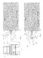
- FIG. 1schematically illustrates an overall system with a probe for tissue-edge characterization, in accordance with an embodiment of the present invention
- FIG. 2schematically illustrates a hand-held system with a probe for tissue-edge characterization, in accordance with another embodiment of the present invention
- FIGS. 3A-3Eschematically illustrate various constructions of the probe for tissue-edge characterization, in accordance with embodiments of the present invention
- FIG. 4schematically illustrates a probe constructed with a cavity, in accordance with an embodiment of the present invention
- FIG. 5schematically illustrates a probe with a coaxial cable operative as a transmission line, in accordance with an embodiment of the present invention
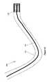
- FIG. 6schematically illustrates a probe constructed in accordance with embodiments of the present invention, connected to an external unit by a flexible coaxial line;
- FIG. 7schematically illustrates components of the external unit in the system of FIG. 6 ;
- FIG. 8illustrates a connector between the external unit components and the coaxial line to the probe, in accordance with the present invention
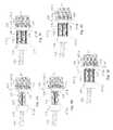
- FIGS. 9A-9Eschematically illustrate various inner constructions of probes for tissue-edge characterization, in accordance with embodiments of the present invention.
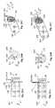
- FIGS. 10A-10Cschematically illustrate an inner conductor and at least one feature, substantially at the proximal end of the inner conductor, for forming at least one additional sharp edge, in accordance with any one of the embodiments of FIGS. 9A-E ;
- FIGS. 11A-11Cschematically illustrate an inner conductor and features, substantially at the proximal end of the inner conductor, for forming additional sharp edges, in accordance with an embodiment of the present invention
- FIGS. 12A-12Cschematically illustrate an inner conductor and features, substantially at the proximal end of the inner conductor, for forming additional sharp edges, in accordance with still another embodiment of the present invention
- FIGS. 13A-13Cschematically illustrate an inner conductor and features, substantially at the proximal end of the inner conductor, for forming additional sharp edges, in accordance with yet another embodiment of the present invention
- FIGS. 14A-14Cschematically illustrate an inner conductor and features, substantially at the proximal end of the inner conductor, for forming additional sharp edges, in accordance with still another embodiment of the present invention
- FIGS. 15A-15Cschematically illustrate an inner conductor and features, substantially at the proximal end of the inner conductor, for forming additional sharp edges, in accordance with yet another embodiment of the present invention
- FIGS. 16A-16Cschematically illustrate an inner conductor and features, substantially at the proximal end of the inner conductor, for forming additional sharp edges, in accordance with still another embodiment of the present invention
- FIGS. 17A-17Cschematically illustrate an inner conductor and at least one feature, substantially at the proximal end of the inner conductor, for forming at least one additional sharp edge, in accordance with yet another embodiment of the present invention
- FIGS. 18A-18Cschematically illustrate an inner conductor and features, substantially at the proximal end of the inner conductor, for forming additional sharp edges, in accordance with still another embodiment of the present invention
- FIGS. 19A-19Cschematically illustrate an inner conductor and at least one feature, substantially at the proximal end of the inner conductor, for forming at least one additional sharp edge, in accordance with yet another embodiment of the present invention
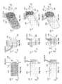
- FIGS. 20A-20Cschematically illustrate an inner conductor and features, substantially at the proximal end of the inner conductor, for forming additional sharp edges, in accordance with still another embodiment of the present invention
- FIGS. 21A-21Cschematically illustrate an inner conductor and features, substantially at the proximal end of the inner conductor, for forming additional sharp edges, in accordance with yet another embodiment of the present invention
- FIGS. 22A-22Cschematically illustrate an inner conductor and features, substantially at the proximal end of the inner conductor, for forming additional sharp edges, in accordance with still another embodiment of the present invention
- FIGS. 23A-23Cschematically illustrate an inner conductor and features, substantially at the proximal end of the inner conductor, for forming additional sharp edges, in accordance with yet another embodiment of the present invention
- FIGS. 24A-24Cschematically illustrate an inner conductor and features, substantially at the proximal end of the inner conductor, for forming additional sharp edges, in accordance with still another embodiment of the present invention
- FIGS. 25A-25Cschematically illustrate an inner conductor and features, substantially at the proximal end of the inner conductor, for forming additional sharp edges, in accordance with yet another embodiment of the present invention
- FIGS. 25D-25Eschematically illustrate the probe associated with FIGS. 25A-25C , with inductive and resistive coupling, respectively, in accordance with embodiments of the present invention
- FIGS. 26A-26Cschematically illustrate an inner conductor and features, substantially at the proximal end of the inner conductor, for forming additional sharp edges, in accordance with still another embodiment of the present invention
- FIGS. 27A-27Cschematically illustrate an inner conductor and features, substantially at the proximal end of the inner conductor, for forming additional sharp edges, in accordance with yet another embodiment of the present invention
- FIGS. 28A-28Cschematically illustrate an inner conductor and features, substantially at the proximal end of the inner conductor, for forming additional sharp edges, in accordance with still another embodiment of the present invention
- FIGS. 29A-29Cschematically illustrate an inner conductor and features, substantially at the proximal end of the inner conductor, for forming additional sharp edges, in accordance with yet another embodiment of the present invention
- FIGS. 30A-30Cschematically illustrate an inner conductor and features, substantially at the proximal end of the inner conductor, for forming additional sharp edges, in accordance with still another embodiment of the present invention
- FIGS. 31A-31Cschematically illustrate an inner conductor and features, substantially at the proximal end of the inner conductor, for forming additional sharp edges, in accordance with yet another embodiment of the present invention
- FIGS. 32A-32Cschematically illustrate an inner conductor and features, substantially at the proximal end of the inner conductor, for forming additional sharp edges, in accordance with still another embodiment of the present invention
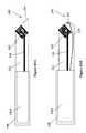
- FIGS. 33A-33Bschematically illustrate an inner construction of a probe for tissue-edge characterization, in accordance with an embodiment of the present invention
- FIGS. 33C-33Dschematically illustrate an inner construction of a probe for tissue-edge characterization, in accordance with another embodiment of the present invention.
- FIGS. 34A-34Bschematically illustrate an inner construction of a probe for tissue-edge characterization, in accordance with still another embodiment of the present invention
- FIG. 35schematically illustrates an inner construction of a probe for tissue-edge characterization, with two inner conductors, in accordance with embodiments of the present invention
- FIG. 36schematically illustrates a proximal view of a probe for tissue-edge characterization, in accordance with an embodiment, based on FIG. 35 ;
- FIGS. 37A and 37Bschematically illustrate a proximal view of another probe for tissue-edge characterization, in accordance with embodiments, based on FIG. 35 ;
- FIG. 38schematically illustrates another inner construction of a probe for tissue-edge characterization, with two inner conductors, in accordance with embodiments of the present invention
- FIG. 39schematically illustrates a proximal view of a probe for tissue-edge characterization, in accordance with an embodiment, based on FIG. 38 ;
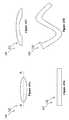
- FIG. 40schematically illustrates another inner construction of a probe for tissue-edge characterization, in accordance with embodiments of the present invention.
- FIG. 41schematically illustrates a proximal view of a probe for tissue-edge characterization, in accordance with an embodiment, based on FIG. 41 ;
- FIG. 42schematically illustrates a probe fitted within a catheter and operative for intracorporeal insertion, in accordance with an embodiment of the present invention
- FIGS. 43A and 43Bschematically illustrate probes associated with resecting devices, in accordance with embodiments of the present invention.
- FIGS. 44A and 44Bschematically illustrate a probe associated with a biopsy device, in accordance with an embodiment of the present invention
- FIGS. 45A-45Dschematically illustrate proximal ends of probes of various shapes, in accordance with embodiments of the present invention.
- FIGS. 46A and 46Bschematically illustrate side views of probes of various shapes, in accordance with embodiments of the present invention.
- FIGS. 47A-47Fschematically illustrate arrays of probes, each operative as a single testing device for tissue-edge characterization, in accordance with embodiments of the present invention.
- FIG. 48schematically illustrates an array of probes arranged as a ring, in accordance with an embodiment of the present invention.
- the present inventionrelates to probes, systems, and methods for tissue characterization by its dielectric properties, wherein a physical feature of the probe is designed to define and delimit a tissue volume, at the tissue edge, where characterization takes place.
- tissue characterizationoccurs substantially in real time.
- FIG. 1schematically illustrates an overall system 110 with a probe 120 for tissue-edge characterization, in accordance with an embodiment of the present invention.
- the probe 120 for tissue-edge characterizationis configured for:
- a novel feature of the probe 120is its including a physical feature 142 , designed to define and delimit the near field 117 of the tissue 15 , where characterization takes place.
- the probe 120 for tissue-edge characterizationcomprises:
- an inner conductor 140having:
- the physical feature 142may be a wire spiral, having an overall diameter D and a wire diameter d, or wire spacing d.
- the feature 142is designed to define and delimit the near field 117 to a tissue volumetric disk, of about a diameter D and a depth d′, which is of about the same order of magnitude as d.
- the relationship between the overall diameter D and the feature size dis about, 1/100 D ⁇ d ⁇ 1 ⁇ 2 D, where D may be between 2 mm and 10 cm. For example:
- dmay be between about 1 mm and about 5 cm.
- dmay be between about 20 ⁇ m and about 1 mm.
- the depth dimension of the tissue volumetric disk, d′is defined by the feature dimensions to about an order of magnitude.
- the at least one feature 142having the at least one additional sharp edge 142 A is operative to enhance the localized electrical fringe fields 112 , in the tissue volumetric disk 115 , sufficiently, so as to make the sum of reflected electric signals from the tissue 15 outside the tissue volumetric disk 115 less than 1/10 of the primary reflected electric signals, thus making the reflected electric signals from the tissue 15 outside the tissue volumetric disk 115 negligible, when compared with the primary reflected electric signals from the tissue 15 inside the tissue volumetric disk 115 .
- tissue characterizationis at a very localized, well-defined near zone 117 , namely, the tissue volumetric disk 115 , with negligible contributions from a far zone 119 .
- the probe 120may be associated with an external control and instrumentation system 130 for signal generation and analysis, which together form the overall system 110 for tissue-edge characterization.
- the probe 120may be associated with a transmission line 156 , directly connected to the probe 120 , or coupled to the probe 120 via a coupler 150 , preferably, at the distal end 129 .
- the transmission line 156leads to the external control and instrumentation system 130 and is operative to transmit a signal to an inner conductor 140 , for applying electric signals to the tissue 15 , and to transmit back a response signal, which corresponds to the primary reflected electric signals.
- the external control and instrumentation system 130may include a signal generator 132 , a signal analyzer 134 , and a controller 136 , with various memories. It will be appreciated that these may be integrated into a single unit.
- a user interfacemay be provided, for example, in the form of a keyboard 135 , for example, to input data such as patient details, date and time of a particular test, and other relevant data.
- the external control and instrumentation system 130may include read and write drives 131 , for example, diskettes, CDs, and (or) DVDs, for input and output of predetermined operating parameters and settings, and (or) in order to store test results.
- a USB port 133for example, for a disk-on-key, and other ports may be provided.
- a display screen 138may display the response and may further be a touch screen, operative as a user interface, additional to or in place of the keyboard 135 .
- the external control and instrumentation system 130may further include output means, for example, a printer or a facsimile.
- the external control and instrumentation system 130may be configured for internet and (or) wireless internet connection.
- FIG. 2schematically illustrates a hand-held system 110 with the probe 120 for tissue-edge characterization, in accordance with another embodiment of the present invention.
- the probe 120is shown as part of a stand-alone, hand-held system 110 configured for internal signal generation and analysis.
- a control and instrumentation system 130 Ais integrated with the probe 120 , for example, within a handle 240 , and includes the signal generator 132 , the signal analyzer 134 , the controller 136 and the various memories.
- the stand-alone, hand-held system 110further includes the display screen 138 , keys 135 as well as additional control keys 135 A, a USB port 133 , internet connection, wireless internet connection, and other features, as known.
- FIGS. 6-8 hereinbelowmay be employed with the stand-alone, hand-held system 110 of FIG. 2 .
- FIGS. 3A-3Eschematically illustrate various constructions of the probe for tissue-edge characterization, in accordance with embodiments of the present invention.
- the probe 120includes an inner conductor 140 surrounded by a dielectric material 173 A, an inner conductor 140 defining the first sharp edge 141 , which in accordance with the present example, is not configured for making contact with the tissue 15 .
- the at least one feature 142is substantially at the proximal end 121 , forming the additional sharp edges 142 A, associated with the sizes D and d, defined in the y-z plane, substantially parallel with the surface 111 of the tissue 15 .
- the additional sharp edges 142 Aare configured for making contact with the tissue 15 .
- the transmission line 156is coupled to an inner conductor 140 , via the coupler 150 .
- the feature 142is exposed to air.
- the feature 142is embedded in a thin insulating layer of dielectric material 173 B, of about 1-200 ⁇ m, for example, of polyimide (Kapton), Polytetrafluoroethylene-PTFE (tefon), PolyEtherImide (Ultem), or another dielectric material, as known.
- dielectric material 173 Bof about 1-200 ⁇ m, for example, of polyimide (Kapton), Polytetrafluoroethylene-PTFE (tefon), PolyEtherImide (Ultem), or another dielectric material, as known.
- a conductive outer sleeve 171 Amay be employed, for surrounding an inner conductor 140 and the dielectric material 173 A within.
- the conductive outer sleeve 171 Aserves as a return path for signals generated at the proximal end 121 of the inner conductor 140 .
- the feature 142is inductively coupled to the conductive outer sleeve 171 A.
- the conductive outer sleeve 171 Ais employed, and the feature 142 is resistively coupled to the conductive outer sleeve 171 A.
- a thin layer of a dielectric material 173 Cis deposited on the proximal end of the feature 142 . Accordingly, the thin layer of a dielectric material 173 C makes contact with the tissue surface 111 , rather then the conductive elements of the feature 142 .
- FIG. 4schematically illustrates a probe constructed with a cavity, in accordance with an embodiment of the present invention.
- the conductive outer sleeve 171 Aextends proximally, beyond the feature 142 , to form a cavity 44 .
- the tissue edgeis characterized within the cavity 44 , as the cavity 44 is adapted for containing the tissue volumetric disk 115 therein.
- the probe outer conductor 171 Amay taper in slightly, at its proximal end 121 .
- FIG. 5schematically illustrates a probe with a coaxial cable operative as a transmission line, in accordance with an embodiment of the present invention.
- the transmission line 156may be constructed as a coaxial cable having an inner conductor 179 , an outer sleeve 171 , and a dielectric material 173 therebetween.
- the coaxial cable 156is coupled to the probe 120 via a coupler 152 .
- FIG. 6schematically illustrates a probe constructed in accordance with embodiments of the present invention, connected to an external unit 52 by a flexible transmission line, for example, a coaxial line 51 .
- a probe 120such as that illustrated in FIGS. 1-3E , coupled to one end of a flexible coaxial line 51 ; the opposite end of coaxial line 51 is connected to an external unit 52 for supplying the electrical signals to the probe.
- the external unit 52is more particularly illustrated in FIG. 7 , as including a computer 53 , a signals source 54 and a digitizing unit 55 .
- the electrical signalsmay be in the form of, for example, a sinusoidal signal, a square pulse, a triangular pulse, a chirped pulse, a modulated pulse, a tailored pulse, or any other pulse known in the art.
- the at least one feature 142with the additional sharp edges 142 A produce a modified coaxial mode, leading to a much stronger electrical fringing field in the tissue, in the volumetric disk 115 .
- the output impedance of the probethus depends to a great extent on the impedance of the biological tissue within the volume where the electric fringing field is present—the volumetric disk 115 .
- the reflected signal detected by the probeis dependent substantially on the impedance and dielectric properties of the tissue itself. This allows a well defined volume of sampled tissue impedance to be calculated without affecting, or being affected by, the surrounding tissues.
- FIG. 7schematically illustrates components of the external unit 52 in the system of FIG. 6 .
- two sets of wires 56 , 57connect the computer 53 to the signals source unit 54 and the digitizing unit 55 .
- One set of wires 56are the timing control wires used to transmit trigger signals to the signal source unit 54 and the digitizing unit 55 ; whereas the other set of wires 57 are the data transfer wires used to transfer data from and to the computer 53 .
- the computer 53controls the signal durations and repetition rates, as well as the signal voltage and form.
- FIG. 8illustrates a connector between the external unit components and a coaxial line to the probe, in accordance with embodiments of the present invention
- FIG. 8illustrates an electrical signal coupler 58 connecting the signal source unit 54 , the digitizing unit 55 , and the probe 120 .
- these connectionsare made by an electrical signal coupler 58 having one leg 58 A connected to the coaxial line 51 , a second leg 58 B connected to the signal source unit 54 , and a third leg 58 C connected to the digitizing unit 55 .
- Digitizing unit 55samples, at a plurality of spaced time intervals, both the incident electrical signals, namely those applied to the probe 120 , and the reflected signals reflected by the examined tissue in the volumetric disk 115 .
- the two time-domain arraysmay also be transformed to the frequency domain, for example, by a conventional FFT program, which is a standard tool for transforming time domain signals to the frequency domain.
- Computer 53compares the electrical characteristics of the reflected electrical signals with respect to those of the incident (applied) electrical signals to provide an indication of the impedance and dielectric properties of the examined tissue. This is done by sampling both electrical signals at a plurality of spaced time intervals, and comparing the voltage magnitudes of the two electrical signals at the spaced time intervals.
- the computercalculated the values of extreme point (Peaks) and special features, like the frequency at which the extreme points appear, the amplitude of the peaks, the average value of the function, the integral under the real part of the dielectric function, the average value of the derivative, the maximum derivative, and the roots of the function. All these values are transferred as an array of parametric representation of the reflected signal to the decision-making program routine. For each value the statistical variance is also calculated.
- the statistical varianceis also calculated.
- the Cole-Cole parametersare transferred to the decision-making program routine.
- the decision making routinecompares the results from any combination of the three types of analysis and the existing data from the memory bank.
- data from known types of tissueis recorded, together with the tissue type name and the statistical variance.
- the statistical varianceis used to define a volume surrounding the curve.
- the matching conditionis a standard statistical process which compares two sets of data. It uses all data for comparison. For example, if the data matches data from a previously taken memory bank data, the program displays the type of tissue from which the databank sample was taken.
- the most similar stored tissue datais chosen as characterizing the examined tissue.
- the most similar tissueis chosen according to the distance (in the phase space) between the two measured points; alternatively, a user defined criterion may be applied.
- the usermay decide to find similarities, at certain measurement points, based on one, two, or more specific calculated parameters, ignoring all the others. For example the user may decide to find similarities only according to the frequency at which a peak appears in the real-part of the dielectric function.
- the decision making routinealso compares the last-point measured to the currently measured point. The result of that process is to indicate merely how similar the two points are to each other, without knowing the type of tissue of the last point.
- the distance between two data pointsis considered as usually in statistics, and the decisions are displayed on the screen together with all data parameters.
- FIGS. 9A-9Eschematically illustrate various inner constructions of probes for tissue-edge characterization, in accordance with embodiments of the present invention.
- the feature 142is a step reduction in diameter of the inner conductor 140 , leading to addition sharp edges, due to the corners formed by the step.
- the probe 120itself may be constructed in various ways, as follows, As seen in FIG. 9A , the inner conductor 140 of the probe 120 is of the diameter D, which generally defines the diameter of the volumetric disk 115 ( FIG. 1 ).
- An inner conductor 140is surrounded by a dielectric material 173 A, which in accordance with the present embodiment, is exposed to air.
- the feature 142being the step reduction in diameter, may be embedded in a dielectric material 173 B. Alternatively, the feature 142 may be exposed to air.
- the probe 120may further include the conductive outer sleeve 171 A.
- the inner conductor 120may be thinner than the diameter D, and the feature 142 may further include a conducting disk 140 A, which defines the diameter D, and from which the step change in diameter takes place.
- the feature 142is inductively coupled to the conductive outer sleeve 17 1 A.
- a layer of dielectric material 173 Cmay be deposited on the feature 142 , so that contact with the tissue surface 111 ( FIG. 1 ) is made by the dielectric material 173 C.
- the conductive outer sleeve 171 Amay be extended beyond the feature 142 , so as to form a cavity 44 , where interaction with the tissue volumetric disk 115 takes place. (See also FIG. 4 .)
- FIGS. 10A-10Cillustrate side, proximal, and perspective views, respectively, of an inner conductor 140 , of FIGS. 9A or 9 B, in accordance with embodiments of the present invention.
- an inner conductor 140has a circular cross section, with the diameter D being substantially equal to 3d.
- an inner conductor 140includes a proximal-end face 147 , which is substantially a flat face, substantially parallel to the y;z plane, and the feature 142 issues from the proximal-end face 147 .
- the at least one feature 142is a step reduction in the diameter D, by d, forming a step 142 B, in the direction of +x.
- the step 142 Bcreates the additional sharp edge 142 A.
- the first sharp edge 141 and the additional sharp edge 142 A of the feature 142form two concentric sharp edges, separated substantially by d, when viewed from the proximal end 121 , as seen in FIG. 10B .
- the additional sharp edge 142 A associated with the size dis operative to enhance the localized electrical fringe fields 112 , in the tissue volumetric disk 115 , of a general diameter D and of a depth of generally d′ which is of about a same order of magnitude as d.
- the enhancementis sufficiently so as to make the reflected electric signals from the tissue 15 outside the tissue volumetric disk 115 negligible, when compared with the primary reflected electric signals.
- FIGS. 11A-11Cillustrate side, proximal, and perspective views, respectively, of an inner conductor 140 , in accordance with another embodiment of the present invention, wherein the at least one feature 142 is at least two step reductions in the diameter D, by d, forming steps 142 B, in the direction of +x, and creating the additional sharp edges 142 A.
- the sharp edges 142 Awhen viewed from the proximal end the sharp edges 142 A appear as concentric circles, separated substantially by d. Furthermore, the first sharp edge 141 is also separated from its adjacent sharp edge 142 A substantially by d. The plurality of sharp edges 142 A enhance the localized electrical fringe fields 112 in the tissue volumetric disk 115 .
- FIGS. 12A-12Cillustrate side, proximal, and perspective views, respectively, of an inner conductor 140 , in accordance with yet another embodiment of the present invention, wherein an inner conductor 140 includes a carved-out portion 149 , in the ⁇ x direction, at the proximal end 121 , and further wherein the at least one feature 142 issues from the carved-out portion 149 , so that the at least one additional sharp edge 142 A is substantially at the same x position as the first sharp edge 141 .
- the at least one feature 142is step reductions in the diameter D, by d, forming steps 142 B, alternating in directions between +x and ⁇ x.
- the sharp edges 142 A formed by the steps 142 Bappear as concentric circles, separated substantially by d, enhancing the localized electrical fringe fields 112 in the tissue volumetric disk 115 .
- the first sharp edge 141is also separated from the nearest sharp edge 142 A, by d.
- step changesare possible, for example, step increases in the diameter D, by d, in either the +x or the ⁇ x direction, and various combinations of the +x and ⁇ x directions.
- FIGS. 13A-13Cillustrate side, proximal, and perspective views, respectively, of an inner conductor 140 , in accordance with still another embodiment of the present invention.
- an inner conductor 140has a polygonal cross section.
- the diameter equivalent of the polygonis defined here as the diameter of a circle of an area equal to the area of the polygon.
- the at least one feature 142is the polygon corners, which define the additional sharp edges 142 A.
- D ⁇ 2d and the polygonis a hexagon, so that when viewed from the proximal end ( FIG. 13B ), the polygon corners are separated by distances d.
- FIGS. 9A-9Emay similarly apply here as well.
- a polygonal disk 140 Amay be employed.
- FIGS. 14A-14Cillustrate side, proximal, and perspective views, respectively, of an inner conductor 140 , in accordance with yet another embodiment of the present invention, illustrating the polygonal conductor 140 , as is FIGS. 13A-13C , wherein the at least one feature 142 further includes step changes in the diameter equivalent D, in a manner analogous to that of FIGS. 11A-11C , so as to create a series of sharp edges 142 A of concentric polygons, separated by distances d, when viewed from the proximal end 121 ( FIG. 14B ).
- FIGS. 9A-9Emay similarly apply here as well.
- a polygonal disk 140 Amay be employed.
- FIGS. 15A-15Cillustrate side, proximal, and perspective views, respectively, of an inner conductor 140 , in accordance with still another embodiment of the present invention, illustrating the polygonal conductor 140 , as is FIGS. 13A-13C , wherein the at least one feature 142 further includes step changes in the diameter equivalent D, alternating in directions between +x and ⁇ x, in a manner analogous to that of FIGS. 12A-12C , again creating a series of sharp edges 142 A of concentric polygons, when viewed from the proximal end 121 ( FIG. 15B ).
- FIGS. 9A-9Emay similarly apply here as well.
- a polygonal disk 140 Amay be employed.
- FIGS. 16A-16Cillustrate side, proximal, and perspective views, respectively, of the inner conductor 140 , in accordance with yet another embodiment of the present invention, wherein D is substantially equal to 2d, and the inner conductor 140 is carved out at the proximal end, as an inverse cone, to a depth no greater than substantially d, in the ⁇ x direction, forming the inverse-cone, carved-out portion 149 , wherein the at least one feature 142 is the inverse cone apex, forming the at least one additional sharp edge 142 A, and further wherein the first sharp edge 141 and the apex 142 A create two concentric sharp edges, separated substantially by d, when viewed from the proximal end 121 ( FIG. 16B ).
- FIGS. 17A-17Cillustrate side, proximal, and perspective views, respectively, of an inner conductor 140 , in accordance with still another embodiment of the present invention.
- an inner conductor 140further includes a proximal-end face 147 , which is substantially flat, in the y;z plane, and D is substantially equal to 2d.
- the at least one feature 142is a needle 142 , having a needle diameter ⁇ ( FIGS. 17A and 17B ), which is preferably no greater than substantially 1 ⁇ 2 d.
- the needle 142issues from the center of the proximal-end face 147 , its proximal end forming the at least one additional sharp edge 142 A, so that the first sharp edge 141 and the needle's sharp edge 142 A create two concentric sharp edges, separated substantially by d, when viewed from the proximal end 121 ( FIG. 17B ).
- FIGS. 18A-18Cillustrate side, proximal, and perspective views, respectively, of the inner conductor 140 , in accordance with still another embodiment of the present invention, wherein the inner conductor 140 is formed with carved grooves 142 , forming concentric sharp edge 142 A, separated substantially by d, when viewed from the proximal end 121 ( FIG. 18B ).
- FIGS. 19A-19Cschematically illustrates the inner conductor 140 , with the feature 142 being a needle issuing from a carved out portion 149 .
- the inner conductor 140has a conical proximal end, the cone being carved out in the ⁇ x direction, to a depth no greater than substantially D, forming an inverse-cone, carved-out portion 149 , wherein the at least one feature 142 is a needle having a needle diameter ⁇ , the needle issuing from the center of the inverse-cone, carved-out portion 149 , its proximal end forming the at least one additional sharp edge 142 A, wherein the first sharp edge 141 and the needle's sharp edge 142 A creates two concentric sharp edges, separated substantially by d, when viewed from the proximal end 121 ( FIG. 19B ), and having substantially the same x position ( FIG. 19A ).
- FIGS. 20A-20Cillustrate side, proximal, and perspective views, respectively, of an inner conductor 140 , in accordance with another embodiment of the present invention.
- An inner conductor 140includes the carved-out portion 149 , in the proximal end 121 , and the at least one feature 142 is a plurality of the needles of the needle diameters ⁇ , no greater than substantially 1 ⁇ 2 d, issuing from the carved-out portion 149 , and separated substantially by distances d, therebetween.
- the needles' proximal endsform a plurality of sharp edges 142 A, separated substantially by d therebetween, when viewed from the proximal end 121 ( FIG. 20B ).
- the carved-out portion 149forms an additional sharp edge 142 A, preferably separated from the first sharp edge 141 substantially by the distance d, ( FIG. 20B ). Preferably, all the sharp edges have substantially the same x position ( FIG. 20A ).
- FIGS. 21A-21Cillustrate side, proximal, and perspective views, respectively, of an inner conductor 140 , in accordance with yet another embodiment of the present invention, wherein the at least one feature 142 is a plurality of the needles of the needle diameters ⁇ , no greater than substantially 1 ⁇ 2 d, issuing from the proximal-end face 147 of an inner conductor 140 , and separated substantially by distances d, therebetween, wherein the needles proximal ends form a plurality of sharp edges 142 A, separated substantially by d therebetween, when viewed from the proximal end 121 ( FIG. 21B ).
- the at least one feature 142is a plurality of the needles of the needle diameters ⁇ , no greater than substantially 1 ⁇ 2 d, issuing from the proximal-end face 147 of an inner conductor 140 , and separated substantially by distances d, therebetween, wherein the needles proximal ends form a plurality of sharp edges 142 A, separated substantially by
- FIGS. 22A-22Cillustrate side, proximal, and perspective views, respectively, of an inner conductor 140 , in accordance with still another embodiment of the present invention.
- the at least one feature 142is a carving of bars on the proximal-end face 147 of an inner conductor 140 .
- the barsare of a thickness of substantially d and are separated substantially by d.
- the barsform a plurality of sharp edges 142 A, separated substantially by d therebetween, when viewed from the proximal end 121 ( FIG. 22B ).
- FIGS. 23A-23Cillustrate side, proximal, and perspective views, respectively, of an inner conductor 140 , in accordance with yet another th embodiment of the present invention.
- an inner conductor 140has a square cross section and the at least one feature 142 is a square checkerboard carving, on the proximal-end face 147 of an inner conductor 140 .
- the checkerboard carvingis of squares of sides that are substantially d, so that the squares form a plurality of sharp edges 142 A, separated substantially by d therebetween, when viewed from the proximal end 121 ( FIG. 23B ).
- FIGS. 24A-24Cillustrate side, proximal, and perspective views, respectively, of an inner conductor 140 , in accordance with still another embodiment of the present invention, similar to that of FIGS. 23A-23C ; however, with an inner conductor 140 having a circular cross section.
- FIGS. 25A-25Cillustrate side, proximal, and perspective views, respectively, of an inner conductor 140 , in accordance with yet another embodiment of the present invention.
- the at least one feature 142is a square grid construction, formed of squares of sides that are substantially d, of the conductive wire of the wire diameter ⁇ , the squares forming a plurality of sharp edges 142 A, separated substantially by d therebetween, when viewed from the proximal end 121 ( FIG. 25B ).
- FIGS. 25D and 25Eschematically illustrate the probe 120 associated with FIGS. 25A-25C , wherein the feature 142 is inductively coupled to the condutctive outer sleeve 171 A ( FIG. 25D ) or resistively coupled to the conductive outer sleeve 171 A ( FIG. 25E ).
- the thin inner conductor shown in FIG. 25Eis preferred to the inner conductor of the diameter of substantially D, shown in FIGS. 25A-25C .
- FIGS. 26A-26Cillustrate side, proximal, and perspective views, respectively, of an inner conductor 140 , in accordance with still another embodiment of the present invention, wherein the at least one feature 142 is a wire construction of slots, of the conductive wire of the wire diameter ⁇ , and further wherein the slots are substantially of a width d, when viewed from the proximal end 121 ( FIG. 26B ).
- FIGS. 9A-9E and FIGS. 25D-25Emay similarly apply here as well.
- FIGS. 27A-27Cillustrate side, proximal, and perspective views, respectively, of an inner conductor 140 , in accordance with yet another embodiment of the present invention, wherein the at least one feature 142 is a wire construction, issuing from an inner conductor 140 and bent into shapes that define the size d, when viewed from the proximal end 121 ( FIG. 27B ), formed of the conductive wire of the wire diameter ⁇ , no greater than substantially 1 ⁇ 2 d.
- FIGS. 9A-9E and FIGS. 25D-25Emay similarly apply here as well.
- FIGS. 28A-28Cillustrate side, proximal, and perspective views, respectively, of an inner conductor 140 , in accordance with a still another embodiment of the present invention, wherein the at least one feature 142 is at least two wire constructions, issuing from an inner conductor 140 and bent into shapes that define the size d, when viewed from the proximal end 121 ( FIG. 28B ), formed of the conductive wire of the wire diameter ⁇ , no greater than substantially 1 ⁇ 2 d.
- FIGS. 9A-9E and FIGS. 25D-25Emay similarly apply here as well.
- FIGS. 29A-29Cillustrate side, proximal, and perspective views, respectively, of an inner conductor 140 , in accordance with yet another embodiment of the present invention, wherein the at least one feature 142 is a circular wire construction, issuing from an inner conductor 140 and bent into shapes that define the size d, when viewed from the proximal end 121 , formed of the conductive wire of the wire diameter ⁇ , no greater than substantially 1 ⁇ 2 d.
- two or more circular wire constructionsmay similarly be employed, for example, arranged as two or more concentric wire constructions, bent into shapes that define the size d, when viewed from the proximal end 121 .
- FIGS. 9A-9E and FIGS. 25D-25Emay similarly apply here as well.
- FIGS. 30A-30Cillustrate side, proximal, and perspective views, respectively, of an inner conductor 140 , in accordance with still another embodiment of the present invention.
- Dis substantially equal to 3 d
- the at least one feature 142is a circular wire construction of the conductive wire of the wire diameter ⁇ , wherein the first sharp edge 141 and the sharp edge 142 A formed by the circular wire construction create two concentric circular sharp edges, separated substantially by d, when viewed from the proximal end 121 ( FIG. 30B ).
- FIGS. 9A-9E and FIGS. 25D-25Emay similarly apply here as well.
- FIGS. 31A-31Cillustrate side, proximal, and perspective views, respectively, of an inner conductor 140 , in accordance with yet another embodiment of the present invention.
- the at least one feature 142is a spiral wire constructions, which is substantially flat, when viewed from the side ( FIG. 35A ).
- the spiralis formed of the conductive wire of the wire diameter ⁇ .
- the sharp edges 142 A formed by the spiral wire constructioncreate a spiral of sharp edges 142 A, separated substantially by d, when viewed from the proximal end 121 ( FIG. 31B ).
- FIGS. 9A-9E and FIGS. 25D-25Emay similarly apply here as well.
- FIGS. 32A-32Cillustrate side, proximal, and perspective views, respectively, of an inner conductor 140 , in accordance with still another embodiment of the present invention.
- the at least one feature 142is a conical spiral wire constructions, as viewed from the side ( FIG. 32A ).
- the spiralis formed of the conductive wire of the wire diameter ⁇ .
- the sharp edges 142 A formed by the spiral wire constructioncreate a spiral of sharp edges 142 A, separated substantially by d, when viewed from the proximal end 121 ( FIG. 32B ).
- FIGS. 9A-9E and FIGS. 25D-25Emay similarly apply here as well.
- FIGS. 33A and 33Billustrate a probe 120 , wherein the feature 142 is helical spiral wire construction, which is inductively coupled.
- FIGS. 33C and 33Dillustrate a probe 120 , wherein the feature 142 is flat spiral wire construction, which is inductively coupled.
- FIGS. 34A and 34Billustrate a probe 120 , wherein the feature 142 is helical spiral wire construction, which is resistively coupled.
- FIG. 35schematically illustrates an inner construction of a probe 120 for tissue-edge characterization, with first and second inner conductors 140 B and 140 C, in accordance with embodiments of the present invention.
- the second inner conductor 140 Cserves as a return path for signals generated at the proximal end 121 of the inner conductor 140 .
- the features 142 associated with the first and second conductorsmay be inductively or resistively coupled.
- FIG. 36schematically illustrates a proximal view of a probe 120 for tissue-edge characterization, in accordance with an embodiment, based on FIG. 35 , and showing a feature 142 associated with the two inner conductors 140 B and 140 C.
- the feature 142may be arranged as two combs that are interlaced, each in communication with a different one of the inner conductors. The present example is thus of inductive coupling.
- FIGS. 37A and 37Bschematically illustrate proximal views of probes 120 for tissue-edge characterization, in accordance with embodiments, based on FIG. 35 , and showing other features 142 , associated with the two inner conductors 140 B and 140 C.
- the feature 142may be arranged as two concentric wire circles, each in communication with a different one of the inner conductors.
- FIG. 37Aillustrates inductive coupling between the two inner conductors, 140 B smf 140 C.
- the feature 142is in physical communication with both the first and the second inner conductors 140 B and 140 C.
- FIG. 37Billustrates resistive coupling between the two inner conductors.
- FIGS. 38-39schematically illustrate another inner construction of a probe 120 for tissue-edge characterization, with two inner conductors, wherein the two inner conductors 140 B and 140 C and the conductive outer sleeve 171 A are operative in the signal path, in accordance with embodiments of the present invention.
- the feature 142may be arranged as three concentric wire circles, two of which being in communication with the two inner conductors 140 B and 140 C, respectively, and a third being in communication with the conductive outer sleeve 171 A.
- FIGS. 40 and 41schematically illustrate another inner construction of a probe 120 for tissue-edge characterization, with a single inner conductor 140 , wherein both the inner conductor 140 and the conductive outer sleeve 17 1 A are operative in the signal path.
- the feature 142may be arranged as two concentric wire circles, one of which being in communication with the inner conductor 140 and the other being in communication with the conductive outer sleeve 171 A.
- the probe 120may be employed as an extracorporeal probe or as an intracorporeal probe, for example, mounted on an endoscopic tool, as taught in commonly owned U.S. patent application Ser. No. 10/567,581, whose disclosure is incorporated herein by reference.
- FIG. 42schematically illustrates a probe fitted within a catheter and operative for intracorporeal insertion, in accordance with an embodiment of the present invention.
- an intracorporeal system 200includes the probe 120 , associated with the transmission line 156 , and fitted within a catheter 202 , for intracorporeal insertion, for example, through a body lumen.
- FIGS. 43A and 43Bschematically illustrate probes associated with resecting devices, in accordance with embodiments of the present invention.
- FIG. 43Aillustrates a probe and resecting tool system 210 , which includes the probe 120 , associated with the transmission line 156 , and mounted on a resecting tool 212 , having a cutting edge 214 .
- Manipulation of the cutting edge 214may be manual, via the handle 240 .
- itmay be electronic, via the control and instrumentation system 130 A, which may be integrated within the handle 240 .
- the cutting edge 214may be controlled via the system 130 A, while the probe 120 may be controlled via the control and instrumentation system 130 of FIG. 1 .
- FIG. 43Billustrates the probe and resecting tool system 210 , having a resection device 215 , powered by a cable 216 .
- Manipulation of the resection device 215may be via the control and instrumentation system 130 A, integrated within the handle 240 , or via the control and instrumentation system 130 of FIG. 1 .
- the resection device 215may be a coil, designed for hot resection, or it may be a laser device, a cryosurgery device, or any resection device, as known.
- the probe 120may be controlled from the control and instrumentation system 130 of FIG. 1
- the resection device 215may be controlled from the control and instrumentation system 130 A within the handle 240 .
- a probe with a cutting toolis also described in commonly owned U.S. patent application Ser. No. 10/558,831 and in U.S. patent application Ser. 10/891,750, filed on Jul. 15, 2004, now U.S. Pat. No. 7,082,325, issued on Jul. 25, 2006, all of whose disclosures are incorporated herein by reference.
- FIGS. 44A and 44Bschematically illustrate a probe associated with a biopsy device, in accordance with an embodiment of the present invention.
- a probe and biopsy system 220includes the probe 120 , associated with the transmission line 156 , and mounted on a biopsy device 220 .
- the biopsy device 220has a biopsy knife 226 , for example, shaped as an ice-cream scoop spoon 226 , having a sharp edge 227 , and manipulated via a manipulator 224 , for collecting tissue samples into a biopsy collection cavity 222 .
- the biopsy system 220may further include the resecting tool 212 .
- biopsy device 220may be manual, or performed from the control and instrumentation system 130 A, which may be integrated within the handle 240 , or from the control and instrumentation system 130 of FIG. 1 . It will be appreciated that the probe 120 may be controlled from the control and instrumentation system 130 of FIG. 1 , while the biopsy knife 226 may be controlled from the control and instrumentation system 130 A within the handle 240 .
- a biopsy needlemay be employed rather than, or in addition to the biopsy knife 226 .
- FIGS. 45A-45Dschematically illustrate proximal ends of probes of various shapes, in accordance with embodiments of the present invention.
- the proximal end 121 of the probe 120may be elliptical.
- the proximal end 121 of the probe 120may be rectangular.
- the proximal end 121 of the probe 120may have other shapes, preferably optimized to fit body anatomical constraints.
- a probe designed for a specific body lumenmay be sized and shaped for that particular lumen, for example, the GI tract.
- the probemay have a specific shape, dedicated to a predetermined tissue specimen shape.
- the probemay be shaped as a ring or as a tube, with the proximal face 121 on the inner wall of the ring or tube, for optimal contact with the tissue specimen.
- FIG. 48 hereinbelowillustrates a ring-shaped array 250 of probes 120 .
- FIGS. 46A-46Bschematically illustrate side views of probes of various shapes, in accordance with embodiments of the present invention.
- the side view of the probe 120may be rectangular.
- the side view of the probe 120may be concave, at the proximal end 121 .
- FIGS. 45A-45D and 46 A- 46 Bare possible. Probes of various shapes are also described in commonly owned U.S. patent application Ser. Nos. 11/350,102, 11/196,732, and 10/558,831, all of whose disclosures are incorporated herein by reference.
- FIGS. 47A-47Fschematically illustrate arrays of probes, each operative as a single testing device for tissue-edge characterization, in accordance with embodiments of the present invention.
- FIG. 47Aillustrates an array 250 of 3 ⁇ 3 probes 120
- FIG. 47Billustrates an array of 7 probes 120
- FIG. 47Cillustrates a row of 3 probes 120 , all viewed from their proximal ends 121 . It will be appreciated that other arrangements are similarly possible.
- FIGS. 47D-47Fillustrate side views of arrays 250 of the probes 120 .
- each of the probeshas a dedicated transmission line.
- a probe 120 Ais associated with a transmission line 156 A
- a probe 120 Bis associated with a transmission line 156 B
- a probe 120 Cis associated with a transmission line 156 C.
- the single transmission line 156is employed, with multiplexing, for example, time multiplexing, or wavelength multiplexing.
- a switch 172is used, operable to selectively route the signals from the transmission line 156 to each of the probes.
- the switch 172is located at the point the transmission line 156 branches off, for example, to the transmission line 156 A, leading to the probe 120 A, the transmission line 156 B, leading to the probe 120 B, and the transmission line 156 C, leading to the probe 120 C.
- spectral band-pass filters 174 A, 174 B, and 174 Care placed along the signal paths to each of the probes 120 A, 120 B, and 120 C, respectively, so that only signals within the given band-pass are transferred to, and back, from each of the probes 120 .
- the band-pass filter for each of the probes 120has a transmission range, with no overlap, so that each of the probes 120 is associated with a different spectral transmission range.
- the probes 120 of the array 250may be grouped into sub-arrays, and each sub-array may have a dedicated transmission line.
- FIG. 48schematically illustrates an array of probes arranged as a ring, in accordance with an embodiment of the present invention. It will be appreciated that a single probe 120 may also be shaped as a ring, a tube, or a cone. Additionally, it will be appreciated that the array 250 may take various shapes, for example, for optimal fit of anatomical constraints, or for optimal characterization of tissue of a predetermined tissue specimen shape.
- the probe 120may be employed for detecting a clean margin, for example, as taught in commonly owned U.S. patent application Ser. No. 10/558,831, whose disclosure is incorporated herein by reference.
- the probe 120may be employed with effective contact, for example, as taught in commonly owned applications U.S. patent application Ser. Nos. 11/350,102 and 11/196,732, whose disclosures are incorporated herein by reference.
- the probe 120may be employed during surgery.
- the feature 142 of the probe 120may be produced by applying a dielectric layer at the proximal end 121 of the probe, to serve as a substrate, and depositing the feature 142 on the substrate, while providing conductive communication with the conductor 140 , or with the first and second conductors 140 B and 140 C. It will be appreciated that a film of dielectric material may further be applied on the proximal side of the feature 142 .
- the fringe field generated in the tissue edgemay extend beyond d′, which generally defines the depth of the tissue volumetric disk.
Landscapes
- Health & Medical Sciences (AREA)
- Life Sciences & Earth Sciences (AREA)
- Surgery (AREA)
- General Health & Medical Sciences (AREA)
- Veterinary Medicine (AREA)
- Engineering & Computer Science (AREA)
- Biomedical Technology (AREA)
- Heart & Thoracic Surgery (AREA)
- Medical Informatics (AREA)
- Molecular Biology (AREA)
- Public Health (AREA)
- Animal Behavior & Ethology (AREA)
- Nuclear Medicine, Radiotherapy & Molecular Imaging (AREA)
- Pathology (AREA)
- Physics & Mathematics (AREA)
- Biophysics (AREA)
- Vascular Medicine (AREA)
- Radiology & Medical Imaging (AREA)
- Immunology (AREA)
- Oncology (AREA)
- Endocrinology (AREA)
- Orthopedic Medicine & Surgery (AREA)
- Measurement And Recording Of Electrical Phenomena And Electrical Characteristics Of The Living Body (AREA)
- Surgical Instruments (AREA)
Abstract
Description
- forming contact with a surface of a tissue;
- applying electric signals, associated with a wavelength λ, to the tissue;
- generating localized electrical and magnetic fringe fields, in the tissue, substantially in a near field, where x<<λ;
- producing primary reflected electric signals from the tissue, substantially only from near field; and
- sensing the primary reflected electric signals, from the near field of the tissue.
- longitudinal axis L along an x-axis of an x;y;z coordinate system; and
- proximal and distal ends, with respect to a tissue, along the x-axis, forming the two endpoints of the longitudinal axis L;
- a first
sharp edge 141, inherently associated with the proximal endpoint; and - the at least one feature, substantially at the proximal end, for forming at least one additional sharp edge, operative to enhance the localized electrical fringe fields in the tissue, within a well defined volume, at the near field, the tissue volume being defined by physical parameters of the feature.
1/100D<d<½D,
- forming contact with a
surface 111 of atissue 15; - applying electric signals, associated with a wavelength λ, to the
tissue 15; - generating localized electrical and magnetic fringe fields112, in the
tissue 15, substantially in anear field 117, where x<<λ; - producing primary reflected electric signals from the
tissue 15, substantially only fromnear field 117; and - sensing the primary reflected electric signals, from the
near field 117 of thetissue 15.
- forming contact with a
- a longitudinal axis L along an x-axis of an x;y;z coordinate system; and
- proximal and
distal ends tissue 15, along the x-axis, forming the two endpoints of the longitudinal axis L; - a first
sharp edge 141, inherently associated with theproximal endpoint 121; and - the at least one
feature 142, substantially at theproximal end 121, for forming at least one additionalsharp edge 142A, operative to enhance the localized electrical fringe fields in the tissue, within a well defined volume, at the near field, the tissue volume being defined by the physical parameters of thefeature 142.
Claims (34)
Priority Applications (1)
| Application Number | Priority Date | Filing Date | Title |
|---|---|---|---|
| US11/797,167US8032211B2 (en) | 2002-01-04 | 2007-05-01 | Probes, systems, and methods for examining tissue according to the dielectric properties thereof |
Applications Claiming Priority (19)
| Application Number | Priority Date | Filing Date | Title |
|---|---|---|---|
| US10/035,428US6813515B2 (en) | 2002-01-04 | 2002-01-04 | Method and system for examining tissue according to the dielectric properties thereof |
| US10/298,196US7505811B2 (en) | 2001-11-19 | 2002-11-18 | Method and apparatus for examining tissue for predefined target cells, particularly cancerous cells, and a probe useful in such method and apparatus |
| US55590104P | 2004-03-23 | 2004-03-23 | |
| US10/891,750US7082325B2 (en) | 2003-07-24 | 2004-07-15 | Method and apparatus for examining a substance, particularly tissue, to characterize its type |
| US10/965,752US7184824B2 (en) | 2002-01-04 | 2004-10-18 | Method and system for examining tissue according to the dielectric properties thereof |
| US64108105P | 2005-01-04 | 2005-01-04 | |
| PCT/IL2005/000330WO2005089065A2 (en) | 2004-03-23 | 2005-03-23 | Clean margin assessment tool |
| US10/558,831US7720532B2 (en) | 2004-03-23 | 2005-03-23 | Clean margin assessment tool |
| US66584205P | 2005-03-29 | 2005-03-29 | |
| US11/196,732US8721565B2 (en) | 2005-08-04 | 2005-08-04 | Device for forming an effective sensor-to-tissue contact |
| PCT/IL2006/000015WO2006072947A2 (en) | 2005-01-04 | 2006-01-04 | Endoscopic system for in-vivo procedures |
| US75955506P | 2006-01-18 | 2006-01-18 | |
| US11/350,102US8116845B2 (en) | 2005-08-04 | 2006-02-09 | Tissue-characterization probe with effective sensor-to-tissue contact |
| PCT/IL2006/000392WO2006103665A2 (en) | 2005-03-29 | 2006-03-29 | Electromagnetic sensors for tissue characterization |
| US11/487,431US7809425B2 (en) | 2003-07-24 | 2006-07-17 | Method and apparatus for examining a substance, particularly tissue, to characterize its type |
| PCT/IL2006/000908WO2007015255A2 (en) | 2005-08-04 | 2006-08-06 | Tissue-characterization probe with effective sensor-to-tissue contact |
| PCT/IL2007/000071WO2007083310A2 (en) | 2006-01-18 | 2007-01-18 | System and method for analysis and treatment of a body tissue |
| US11/705,143US8019411B2 (en) | 2002-01-04 | 2007-02-12 | Probes, systems, and methods for examining tissue according to the dielectric properties thereof |
| US11/797,167US8032211B2 (en) | 2002-01-04 | 2007-05-01 | Probes, systems, and methods for examining tissue according to the dielectric properties thereof |
Related Parent Applications (11)
| Application Number | Title | Priority Date | Filing Date |
|---|---|---|---|
| US10/298,196Continuation-In-PartUS7505811B2 (en) | 2001-11-19 | 2002-11-18 | Method and apparatus for examining tissue for predefined target cells, particularly cancerous cells, and a probe useful in such method and apparatus |
| PCT/IL2005/000330Continuation-In-PartWO2005089065A2 (en) | 2002-01-04 | 2005-03-23 | Clean margin assessment tool |
| US10/558,831Continuation-In-PartUS7720532B2 (en) | 2002-01-04 | 2005-03-23 | Clean margin assessment tool |
| PCT/IL2006/000015Continuation-In-PartWO2006072947A2 (en) | 2002-01-04 | 2006-01-04 | Endoscopic system for in-vivo procedures |
| PCT/IL2006/000392Continuation-In-PartWO2006103665A2 (en) | 2002-01-04 | 2006-03-29 | Electromagnetic sensors for tissue characterization |
| US11/487,431Continuation-In-PartUS7809425B2 (en) | 2002-01-04 | 2006-07-17 | Method and apparatus for examining a substance, particularly tissue, to characterize its type |
| PCT/IL2006/000908Continuation-In-PartWO2007015255A2 (en) | 2002-01-04 | 2006-08-06 | Tissue-characterization probe with effective sensor-to-tissue contact |
| US11/567,581Continuation-In-PartUS7471103B2 (en) | 2006-12-06 | 2006-12-06 | Method for implementing complex logic within a memory array |
| PCT/IL2007/000071Continuation-In-PartWO2007083310A2 (en) | 2002-01-04 | 2007-01-18 | System and method for analysis and treatment of a body tissue |
| US11/705,143Continuation-In-PartUS8019411B2 (en) | 2002-01-04 | 2007-02-12 | Probes, systems, and methods for examining tissue according to the dielectric properties thereof |
| US11/797,167Continuation-In-PartUS8032211B2 (en) | 2002-01-04 | 2007-05-01 | Probes, systems, and methods for examining tissue according to the dielectric properties thereof |
Related Child Applications (4)
| Application Number | Title | Priority Date | Filing Date |
|---|---|---|---|
| US10/965,752Continuation-In-PartUS7184824B2 (en) | 2002-01-04 | 2004-10-18 | Method and system for examining tissue according to the dielectric properties thereof |
| US11/350,102Continuation-In-PartUS8116845B2 (en) | 2002-01-04 | 2006-02-09 | Tissue-characterization probe with effective sensor-to-tissue contact |
| US11/487,431Continuation-In-PartUS7809425B2 (en) | 2002-01-04 | 2006-07-17 | Method and apparatus for examining a substance, particularly tissue, to characterize its type |
| US11/797,167Continuation-In-PartUS8032211B2 (en) | 2002-01-04 | 2007-05-01 | Probes, systems, and methods for examining tissue according to the dielectric properties thereof |
Publications (2)
| Publication Number | Publication Date |
|---|---|
| US20080021343A1 US20080021343A1 (en) | 2008-01-24 |
| US8032211B2true US8032211B2 (en) | 2011-10-04 |
Family
ID=38972351
Family Applications (1)
| Application Number | Title | Priority Date | Filing Date |
|---|---|---|---|
| US11/797,167Expired - Fee RelatedUS8032211B2 (en) | 2002-01-04 | 2007-05-01 | Probes, systems, and methods for examining tissue according to the dielectric properties thereof |
Country Status (1)
| Country | Link |
|---|---|
| US (1) | US8032211B2 (en) |
Cited By (13)
| Publication number | Priority date | Publication date | Assignee | Title |
|---|---|---|---|---|
| US20080154090A1 (en)* | 2005-01-04 | 2008-06-26 | Dune Medical Devices Ltd. | Endoscopic System for In-Vivo Procedures |
| US20080287750A1 (en)* | 2002-01-04 | 2008-11-20 | Dune Medical Devices Ltd. | Ergonomic probes |
| US20130190646A1 (en)* | 2010-07-21 | 2013-07-25 | Kyma Medical Technologies Ltd. | Implantable Dielectrometer |
| US8721565B2 (en) | 2005-08-04 | 2014-05-13 | Dune Medical Devices Ltd. | Device for forming an effective sensor-to-tissue contact |
| US9526460B2 (en) | 2005-08-04 | 2016-12-27 | Dune Medical Devices Ltd. | Tissue-characterization probe with effective sensor-to-tissue contact |
| US10149629B2 (en) | 2012-12-21 | 2018-12-11 | Pit-Radwar Spolka Akcyjna | Measuring system for a probe |
| US10548485B2 (en) | 2015-01-12 | 2020-02-04 | Zoll Medical Israel Ltd. | Systems, apparatuses and methods for radio frequency-based attachment sensing |
| US10588599B2 (en) | 2008-05-27 | 2020-03-17 | Zoll Medical Israel Ltd. | Methods and systems for determining fluid content of tissue |
| US10680324B2 (en) | 2013-10-29 | 2020-06-09 | Zoll Medical Israel Ltd. | Antenna systems and devices and methods of manufacture thereof |
| US11013420B2 (en) | 2014-02-05 | 2021-05-25 | Zoll Medical Israel Ltd. | Systems, apparatuses and methods for determining blood pressure |
| US11020002B2 (en) | 2017-08-10 | 2021-06-01 | Zoll Medical Israel Ltd. | Systems, devices and methods for physiological monitoring of patients |
| US11259715B2 (en) | 2014-09-08 | 2022-03-01 | Zoll Medical Israel Ltd. | Monitoring and diagnostics systems and methods |
| US12038399B2 (en) | 2020-03-25 | 2024-07-16 | Samsung Electronics Co., Ltd. | Apparatus and method for analyzing biological material component, and apparatus for measuring impedance |
Families Citing this family (19)
| Publication number | Priority date | Publication date | Assignee | Title |
|---|---|---|---|---|
| US20070255169A1 (en)* | 2001-11-19 | 2007-11-01 | Dune Medical Devices Ltd. | Clean margin assessment tool |
| US7505811B2 (en)* | 2001-11-19 | 2009-03-17 | Dune Medical Devices Ltd. | Method and apparatus for examining tissue for predefined target cells, particularly cancerous cells, and a probe useful in such method and apparatus |
| US20060177852A1 (en)* | 2001-12-12 | 2006-08-10 | Do-Coop Technologies Ltd. | Solid-fluid composition |
| US8032211B2 (en) | 2002-01-04 | 2011-10-04 | Dune Medical Devices Ltd. | Probes, systems, and methods for examining tissue according to the dielectric properties thereof |
| US8019411B2 (en)* | 2002-01-04 | 2011-09-13 | Dune Medical Devices Ltd. | Probes, systems, and methods for examining tissue according to the dielectric properties thereof |
| US7809425B2 (en)* | 2003-07-24 | 2010-10-05 | Dune Medical Devices Ltd. | Method and apparatus for examining a substance, particularly tissue, to characterize its type |
| US9750425B2 (en) | 2004-03-23 | 2017-09-05 | Dune Medical Devices Ltd. | Graphical user interfaces (GUI), methods and apparatus for data presentation |
| ES2434851T3 (en)* | 2005-03-29 | 2013-12-17 | Dune Medical Devices Ltd. | Electromagnetic sensors for tissue characterization |
| US9177770B2 (en)* | 2007-07-11 | 2015-11-03 | Excellims Corporation | Ion gate method and apparatus |
| DE102008064405A1 (en)* | 2008-06-02 | 2009-12-10 | Rohde & Schwarz Gmbh & Co. Kg | Measuring device and method for determining tissue parameters |
| JP5077171B2 (en) | 2008-09-24 | 2012-11-21 | 富士通株式会社 | Aperture antenna |
| US9844347B2 (en)* | 2009-02-13 | 2017-12-19 | The Ohio State University | Electromagnetic system and method |
| WO2010093479A2 (en)* | 2009-02-13 | 2010-08-19 | The Ohio State University Research Foundation | Electromagnetic system and method |
| CN102573622B (en)* | 2009-08-03 | 2016-01-27 | 沙丘医疗设备有限公司 | For the electromagnetic transducer measured experimenter |
| CN102770085B (en) | 2009-08-03 | 2015-06-10 | 沙丘医疗设备有限公司 | Surgical tool |
| US10117596B2 (en)* | 2013-08-19 | 2018-11-06 | Prolung, Inc. | Method for diagnosing a malignant lung tumor |
| DE102015119180A1 (en)* | 2015-11-06 | 2017-05-11 | Infineon Technologies Ag | Electromagnetic wave sensor to determine a hydration status of body tissue in vivo |
| US11249068B2 (en) | 2015-11-09 | 2022-02-15 | Ohio State Innovation Foundation | Non-invasive method for detecting a deadly form of malaria |
| CN112006687B (en)* | 2019-05-28 | 2025-08-05 | 思澜科技(成都)有限公司 | Probe and device for bioimpedance testing |
Citations (125)
| Publication number | Priority date | Publication date | Assignee | Title |
|---|---|---|---|---|
| US3830224A (en) | 1972-12-19 | 1974-08-20 | Vanzetti Infrared Computer Sys | Means for detecting changes in the temperature of the skin |
| USRE30317E (en) | 1972-11-15 | 1980-07-01 | Hellige Gmbh | Method and apparatus for determining the perfusion efficiency factor of animal tissue |
| US4291708A (en) | 1977-11-02 | 1981-09-29 | Yeda Research & Development Co. Ltd. | Apparatus and method for detection of tumors in tissue |
| US4344440A (en) | 1980-04-01 | 1982-08-17 | Trygve Aaby | Microprobe for monitoring biophysical phenomena associated with cardiac and neural activity |
| US4458694A (en) | 1977-11-02 | 1984-07-10 | Yeda Research & Development Co., Ltd. | Apparatus and method for detection of tumors in tissue |
| US4537203A (en) | 1980-10-21 | 1985-08-27 | Tokyo Shibaura Denki Kabushiki Kaisha | Abnormal cell detecting device |
| US4539640A (en) | 1982-01-12 | 1985-09-03 | Tasc Ltd. | Reconstruction system and methods for impedance imaging |
| USRE32000E (en) | 1978-05-22 | 1985-10-08 | B.C.S.I. Laboratories, Inc. | Device for use in early detection of breast cancer |
| US4617939A (en) | 1982-04-30 | 1986-10-21 | The University Of Sheffield | Tomography |
| US4625171A (en) | 1983-02-14 | 1986-11-25 | Hitachi, Ltd. | Imaging apparatus using nuclear magnetic resonance |
| US4682594A (en) | 1985-03-11 | 1987-07-28 | Mcm Laboratories, Inc. | Probe-and-fire lasers |
| US4689567A (en) | 1984-06-01 | 1987-08-25 | Advanced Nmr Systems, Inc. | NMR Fourier imaging from multiple echoes |
| DE3637549A1 (en) | 1986-11-04 | 1988-05-11 | Hans Dr Med Rosenberger | Measuring device for testing the dielectric properties of biological tissues |
| US4751464A (en) | 1987-05-04 | 1988-06-14 | Advanced Nmr Systems, Inc. | Cavity resonator with improved magnetic field uniformity for high frequency operation and reduced dielectric heating in NMR imaging devices |
| US4768513A (en) | 1986-04-21 | 1988-09-06 | Agency Of Industrial Science And Technology | Method and device for measuring and processing light |
| US4779624A (en) | 1986-05-21 | 1988-10-25 | Olympus Optical Co., Ltd. | Ultrasonic endoscope |
| US4785806A (en) | 1987-01-08 | 1988-11-22 | Yale University | Laser ablation process and apparatus |
| US5115137A (en) | 1989-02-22 | 1992-05-19 | Spectraphos Ab | Diagnosis by means of fluorescent light emission from tissue |
| US5143079A (en) | 1989-08-02 | 1992-09-01 | Yeda Research And Development Company Limited | Apparatus for detection of tumors in tissue |
| US5227730A (en) | 1992-09-14 | 1993-07-13 | Kdc Technology Corp. | Microwave needle dielectric sensors |
| US5277730A (en) | 1987-12-16 | 1994-01-11 | At&T Bell Laboratories | Methods of recoating spliced lengths of optical fibers |
| US5334941A (en) | 1992-09-14 | 1994-08-02 | Kdc Technology Corp. | Microwave reflection resonator sensors |
| US5383454A (en) | 1990-10-19 | 1995-01-24 | St. Louis University | System for indicating the position of a surgical probe within a head on an image of the head |
| US5442290A (en) | 1992-08-04 | 1995-08-15 | The Regents Of The University Of California | MRI gradient drive current control using all digital controller |
| US5482041A (en) | 1992-06-05 | 1996-01-09 | Wilk; Peter J. | Medical investigation system and related method |
| US5482047A (en) | 1992-11-23 | 1996-01-09 | Advanced Technology Laboratories, Inc. | Intraoperative ultrasound probe |
| US5558092A (en) | 1995-06-06 | 1996-09-24 | Imarx Pharmaceutical Corp. | Methods and apparatus for performing diagnostic and therapeutic ultrasound simultaneously |
| US5572132A (en) | 1995-08-15 | 1996-11-05 | Pulyer; Yuly M. | MRI probe for external imaging |
| US5630426A (en) | 1995-03-03 | 1997-05-20 | Neovision Corporation | Apparatus and method for characterization and treatment of tumors |
| DE19705260A1 (en) | 1996-02-20 | 1997-08-21 | Hauni Maschinenbau Ag | Detecting at least one characteristic of material by evaluating HF resonator tuning |
| US5678565A (en) | 1992-12-21 | 1997-10-21 | Artann Corporation | Ultrasonic elasticity imaging method and device |
| US5699804A (en) | 1995-06-07 | 1997-12-23 | Siemens Aktiengesellschaft | Therapy apparatus having a source of acoustic waves |
| US5704355A (en) | 1994-07-01 | 1998-01-06 | Bridges; Jack E. | Non-invasive system for breast cancer detection |
| US5727569A (en) | 1996-02-20 | 1998-03-17 | Cardiothoracic Systems, Inc. | Surgical devices for imposing a negative pressure to fix the position of cardiac tissue during surgery |
| US5735278A (en) | 1996-03-15 | 1998-04-07 | National Research Council Of Canada | Surgical procedure with magnetic resonance imaging |
| US5744971A (en) | 1994-09-09 | 1998-04-28 | Chan; Tsing Yee Amy | Device and apparatus for measuring dielectric properties of materials |
| US5758646A (en) | 1994-09-12 | 1998-06-02 | U.S. Philips Corporation | Magnetic resonance imaging method with pulse sequence optimization and device for such method |
| US5800350A (en) | 1993-11-01 | 1998-09-01 | Polartechnics, Limited | Apparatus for tissue type recognition |
| US5810742A (en) | 1994-10-24 | 1998-09-22 | Transcan Research & Development Co., Ltd. | Tissue characterization based on impedance images and on impedance measurements |
| US5821410A (en) | 1996-09-20 | 1998-10-13 | Regents Of The University Of California | Scanning tip microwave near field microscope |
| US5829437A (en) | 1994-07-01 | 1998-11-03 | Interstitial, Inc. | Microwave method and system to detect and locate cancers in heterogenous tissues |
| DE19734978A1 (en) | 1997-02-12 | 1999-02-18 | Hauni Maschinenbau Ag | Material characteristic determination method |
| US5884239A (en) | 1995-12-27 | 1999-03-16 | Romanik, Jr.; Carl J. | Optical system for accurate monitoring of the position and orientation of an object |
| US5900618A (en) | 1997-08-26 | 1999-05-04 | University Of Maryland | Near-field scanning microwave microscope having a transmission line with an open end |
| US5927284A (en) | 1995-09-20 | 1999-07-27 | Medtronic, Inc | Method and apparatus for temporarily immobilizing a local area of tissue |
| US6004263A (en) | 1996-03-13 | 1999-12-21 | Hihon Kohden Corporation | Endoscope with detachable operation unit and insertion unit |
| US6010455A (en) | 1995-11-27 | 2000-01-04 | Hill-Rom, Inc. | Skin perfusion evaluation apparatus |
| US6026323A (en) | 1997-03-20 | 2000-02-15 | Polartechnics Limited | Tissue diagnostic system |
| US6055451A (en) | 1997-12-12 | 2000-04-25 | Spectrx, Inc. | Apparatus and method for determining tissue characteristics |
| US6061589A (en) | 1994-07-01 | 2000-05-09 | Interstitial, Inc. | Microwave antenna for cancer detection system |
| US6064081A (en) | 1994-11-10 | 2000-05-16 | Lawrence Semiconductor Research Laboratory, Inc. | Silicon-germanium-carbon compositions and processes thereof |
| US6071239A (en) | 1997-10-27 | 2000-06-06 | Cribbs; Robert W. | Method and apparatus for lipolytic therapy using ultrasound energy |
| US6081738A (en) | 1998-01-15 | 2000-06-27 | Lumend, Inc. | Method and apparatus for the guided bypass of coronary occlusions |
| US6086534A (en) | 1997-03-07 | 2000-07-11 | Cardiogenesis Corporation | Apparatus and method of myocardial revascularization using ultrasonic pulse-echo distance ranging |
| US6090041A (en) | 1999-02-16 | 2000-07-18 | Regents Of The University Of California | vacuum actuated surgical retractor and methods |
| US6093150A (en) | 1997-12-31 | 2000-07-25 | Acuson Corporation | Ultrasound otoscope |
| US6109270A (en) | 1997-02-04 | 2000-08-29 | The United States Of America As Represented By The Administrator Of The National Aeronautics And Space Administration | Multimodality instrument for tissue characterization |
| US6135968A (en) | 1997-09-10 | 2000-10-24 | Scantek Medical, Inc. | Differential temperature measuring device and method |
| US6167297A (en) | 1999-05-05 | 2000-12-26 | Benaron; David A. | Detecting, localizing, and targeting internal sites in vivo using optical contrast agents |
| US6173604B1 (en) | 1996-09-20 | 2001-01-16 | The Regents Of The University Of California | Scanning evanescent electro-magnetic microscope |
| US6203533B1 (en) | 1995-06-07 | 2001-03-20 | Asahi Kogaku Kogyo Kabushiki Kaisha | Treatment accessory for an endoscope |
| US6233479B1 (en) | 1998-09-15 | 2001-05-15 | The Regents Of The University Of California | Microwave hematoma detector |
| US6258576B1 (en) | 1996-06-19 | 2001-07-10 | Board Of Regents, The University Of Texas System | Diagnostic method and apparatus for cervical squamous intraepithelial lesions in vitro and in vivo using fluorescence spectroscopy |
| US6280704B1 (en) | 1993-07-30 | 2001-08-28 | Alliance Pharmaceutical Corp. | Ultrasonic imaging system utilizing a long-persistence contrast agent |
| US6287302B1 (en) | 1999-06-14 | 2001-09-11 | Fidus Medical Technology Corporation | End-firing microwave ablation instrument with horn reflection device |
| US6315981B1 (en) | 1989-12-22 | 2001-11-13 | Imarx Therapeutics, Inc. | Gas filled microspheres as magnetic resonance imaging contrast agents |
| US6321106B1 (en) | 1996-11-05 | 2001-11-20 | Jerome Lemelson | System and method for treating select tissue in a living being |
| US20010051774A1 (en) | 2000-02-28 | 2001-12-13 | Peter Littrup | Multidimensional bioelectrical tissue analyzer |
| US6331166B1 (en) | 1998-03-03 | 2001-12-18 | Senorx, Inc. | Breast biopsy system and method |
| US6370426B1 (en) | 1999-04-20 | 2002-04-09 | Nova Technology Corporation | Method and apparatus for measuring relative hydration of a substrate |
| US6375634B1 (en) | 1997-11-19 | 2002-04-23 | Oncology Innovations, Inc. | Apparatus and method to encapsulate, kill and remove malignancies, including selectively increasing absorption of x-rays and increasing free-radical damage to residual tumors targeted by ionizing and non-ionizing radiation therapy |
| US6377841B1 (en) | 2000-03-31 | 2002-04-23 | Vanderbilt University | Tumor demarcation using optical spectroscopy |
| US6380747B1 (en) | 1998-05-12 | 2002-04-30 | Jentek Sensors, Inc. | Methods for processing, optimization, calibration and display of measured dielectrometry signals using property estimation grids |
| US20020055754A1 (en) | 1999-10-05 | 2002-05-09 | Kevin Ranucci | Utrasonic probe device with rapid attachment and detachment means |
| US20020059938A1 (en) | 2000-02-18 | 2002-05-23 | Fogarty Thomas J. | Device for accurately marking tissue |
| US6397095B1 (en) | 1999-03-01 | 2002-05-28 | The Trustees Of The University Of Pennsylvania | Magnetic resonance—electrical impedance tomography |
| US20020072676A1 (en) | 1997-10-27 | 2002-06-13 | Afanassieva Natalia I. | Apparatus and method ofor spectroscopic analysis of human or animal tissue in or body fluids |
| US6405733B1 (en) | 2000-02-18 | 2002-06-18 | Thomas J. Fogarty | Device for accurately marking tissue |
| US6411103B1 (en) | 1999-06-03 | 2002-06-25 | Hauni Maschinenbau Ag | Stray-field sensor |
| US20020120265A1 (en) | 1999-12-23 | 2002-08-29 | Mayo Foundation For Medical Education And Research | Symmetric conization electrocautery device |
| US20020148277A1 (en) | 2001-04-11 | 2002-10-17 | Manabu Umeda | Method of making ultrasonic probe and ultrasonic probe |
| US6500112B1 (en) | 1994-03-30 | 2002-12-31 | Brava, Llc | Vacuum dome with supporting rim and rim cushion |
| US20030036674A1 (en) | 2001-07-26 | 2003-02-20 | Bouton Chad Edward | Electromagnetic sensors for biological tissue applications and methods for their use |
| US20030045798A1 (en) | 2001-09-04 | 2003-03-06 | Richard Hular | Multisensor probe for tissue identification |
| US6530944B2 (en) | 2000-02-08 | 2003-03-11 | Rice University | Optically-active nanoparticles for use in therapeutic and diagnostic methods |
| US20030062897A1 (en) | 1997-11-26 | 2003-04-03 | Belt Kenneth W. | Peripheral vascular array |
| US6544185B2 (en) | 2000-10-23 | 2003-04-08 | Valentino Montegrande | Ultrasound imaging marker and method of use |
| US6546787B1 (en) | 1999-03-25 | 2003-04-15 | Regents Of The University Of Minnesota | Means and method for modeling and treating specific tissue structures |
| US6592520B1 (en) | 2001-07-31 | 2003-07-15 | Koninklijke Philips Electronics N.V. | Intravascular ultrasound imaging apparatus and method |
| US6597185B1 (en) | 2000-09-20 | 2003-07-22 | Neocera, Inc. | Apparatus for localized measurements of complex permittivity of a material |
| US20030138378A1 (en) | 2001-11-19 | 2003-07-24 | Dune Medical Devices Ltd. | Method and apparatus for examining tissue for predefined target cells, particularly cancerous cells, and a probe useful in such method and apparatus |
| US20030146814A1 (en) | 2000-03-06 | 2003-08-07 | Wiltshire Michael Charles Keogh | Structure with switchable magnetic properties |
| US20030163037A1 (en) | 1992-08-14 | 2003-08-28 | British Telecommunications Public Limited Company | Surgical navigation |
| US20030171664A1 (en) | 2000-02-25 | 2003-09-11 | Wendlandt Jeffrey M | Diagnostic catheter using a vacuum for tissue positioning |
| US20030187347A1 (en) | 2001-02-15 | 2003-10-02 | Robin Medical Inc. | Endoscopic examining apparatus particularly useful in MRI, a probe useful in such apparatus, and a method of making such probe |
| US20030187366A1 (en) | 2002-01-04 | 2003-10-02 | Dune Medical Devices Ltd. | Method and system for examining tissue according to the dielectric properties thereof |
| US20030199753A1 (en) | 2002-04-23 | 2003-10-23 | Ethicon Endo-Surgery | MRI compatible biopsy device with detachable probe |
| US20030216648A1 (en) | 2002-05-14 | 2003-11-20 | Lizzi Frederic L. | Ultrasound method and system |
| US20030229343A1 (en) | 2002-06-06 | 2003-12-11 | Albrecht Thomas E. | Device for removal of tissue lesions |
| US6671540B1 (en) | 1990-08-10 | 2003-12-30 | Daryl W. Hochman | Methods and systems for detecting abnormal tissue using spectroscopic techniques |
| US20040065158A1 (en) | 2001-03-06 | 2004-04-08 | Schrepfer Thomas W. | Method and device for determining the concentration of a substance in body liquid |
| US6722371B1 (en) | 2000-02-18 | 2004-04-20 | Thomas J. Fogarty | Device for accurately marking tissue |
| US6741077B2 (en) | 2000-08-25 | 2004-05-25 | Yamagata Public Corporation For The Development Of Industry | Electron spin resonance measurement method and measurement device for measuring ESR within the interior of large samples |
| US6766185B2 (en) | 2000-05-22 | 2004-07-20 | The Board Of Trustees Of The Leland Stanford Junior University | Transmission line techniques for MRI catheter coil miniaturization and tuning |
| US20040254457A1 (en) | 2003-06-02 | 2004-12-16 | Van Der Weide Daniel Warren | Apparatus and method for near-field imaging of tissue |
| US20050021019A1 (en) | 2003-07-24 | 2005-01-27 | Dune Medical Devices Ltd. | Method and apparatus for examining a substance, particularly tissue, to characterize its type |
| US20050107717A1 (en) | 2003-10-02 | 2005-05-19 | Omron Healthcare Co., Ltd, | Method and device for calculating visceral fat |
| US20050119648A1 (en) | 2003-12-02 | 2005-06-02 | Swanson David K. | Surgical methods and apparatus for stimulating tissue |
| US6909084B2 (en) | 2000-08-31 | 2005-06-21 | Toudai Tlo, Ltd | Optical tactile sensor having a transparent elastic tactile portion |
| US20050159689A1 (en) | 2004-01-20 | 2005-07-21 | Chuck Olson | Ergonomic reflexology device |
| US6936003B2 (en) | 2002-10-29 | 2005-08-30 | Given Imaging Ltd | In-vivo extendable element device and system, and method of use |
| US6962587B2 (en) | 2000-07-25 | 2005-11-08 | Rita Medical Systems, Inc. | Method for detecting and treating tumors using localized impedance measurement |
| US20060253107A1 (en) | 2004-03-23 | 2006-11-09 | Dune Medical Devices Ltd. | Clean margin assessment tool |
| US20060264738A1 (en) | 2003-07-24 | 2006-11-23 | Dune Medical Devices Ltd. | Method and apparatus for examining a substance, particularly tissue, to characterize its type |
| US20070032747A1 (en) | 2005-08-04 | 2007-02-08 | Dune Medical Devices Ltd. | Tissue-characterization probe with effective sensor-to-tissue contact |
| US20070032739A1 (en) | 2005-08-04 | 2007-02-08 | Dune Medical Devices Ltd. | Device for forming an effective sensor-to-tissue contact |
| US20070092059A1 (en) | 2005-10-25 | 2007-04-26 | Jeffrey Wayne Eberhard | Breast immobilization device and method of imaging the breast |
| US20070179397A1 (en) | 2002-01-04 | 2007-08-02 | Dune Medical Devices Ltd. | Probes, systems, and methods for examining tissue according to the dielectric properties thereof |
| US20070255169A1 (en) | 2001-11-19 | 2007-11-01 | Dune Medical Devices Ltd. | Clean margin assessment tool |
| US20080021343A1 (en) | 2002-01-04 | 2008-01-24 | Dune Medical Devices Ltd. | Probes, systems, and methods for examining tissue according to the dielectric properties thereof |
| JP2003516214A5 (en) | 2000-11-24 | 2008-01-31 | ||
| US20080039742A1 (en) | 2004-03-23 | 2008-02-14 | Dune Medical Devices Ltd. | Clean margin assessment tool |
| US20080154090A1 (en) | 2005-01-04 | 2008-06-26 | Dune Medical Devices Ltd. | Endoscopic System for In-Vivo Procedures |
| US20080287750A1 (en) | 2002-01-04 | 2008-11-20 | Dune Medical Devices Ltd. | Ergonomic probes |
| US20090062637A1 (en) | 2005-03-29 | 2009-03-05 | Dune Medical Devices Ltd. | Electromagnetic Sensors for Tissue Characterization |
Family Cites Families (1)
| Publication number | Priority date | Publication date | Assignee | Title |
|---|---|---|---|---|
| GB2357149A (en) | 1999-12-08 | 2001-06-13 | Topspin Medical | MRI using non-homogeneous static field |
- 2007
- 2007-05-01USUS11/797,167patent/US8032211B2/ennot_activeExpired - Fee Related
Patent Citations (145)
| Publication number | Priority date | Publication date | Assignee | Title |
|---|---|---|---|---|
| USRE30317E (en) | 1972-11-15 | 1980-07-01 | Hellige Gmbh | Method and apparatus for determining the perfusion efficiency factor of animal tissue |
| US3830224A (en) | 1972-12-19 | 1974-08-20 | Vanzetti Infrared Computer Sys | Means for detecting changes in the temperature of the skin |
| US4291708A (en) | 1977-11-02 | 1981-09-29 | Yeda Research & Development Co. Ltd. | Apparatus and method for detection of tumors in tissue |
| US4458694A (en) | 1977-11-02 | 1984-07-10 | Yeda Research & Development Co., Ltd. | Apparatus and method for detection of tumors in tissue |
| USRE32000E (en) | 1978-05-22 | 1985-10-08 | B.C.S.I. Laboratories, Inc. | Device for use in early detection of breast cancer |
| US4344440A (en) | 1980-04-01 | 1982-08-17 | Trygve Aaby | Microprobe for monitoring biophysical phenomena associated with cardiac and neural activity |
| US4537203A (en) | 1980-10-21 | 1985-08-27 | Tokyo Shibaura Denki Kabushiki Kaisha | Abnormal cell detecting device |
| US4539640A (en) | 1982-01-12 | 1985-09-03 | Tasc Ltd. | Reconstruction system and methods for impedance imaging |
| US4617939A (en) | 1982-04-30 | 1986-10-21 | The University Of Sheffield | Tomography |
| US4625171A (en) | 1983-02-14 | 1986-11-25 | Hitachi, Ltd. | Imaging apparatus using nuclear magnetic resonance |
| US4689567A (en) | 1984-06-01 | 1987-08-25 | Advanced Nmr Systems, Inc. | NMR Fourier imaging from multiple echoes |
| US4682594A (en) | 1985-03-11 | 1987-07-28 | Mcm Laboratories, Inc. | Probe-and-fire lasers |
| US4768513A (en) | 1986-04-21 | 1988-09-06 | Agency Of Industrial Science And Technology | Method and device for measuring and processing light |
| US4779624A (en) | 1986-05-21 | 1988-10-25 | Olympus Optical Co., Ltd. | Ultrasonic endoscope |
| DE3637549A1 (en) | 1986-11-04 | 1988-05-11 | Hans Dr Med Rosenberger | Measuring device for testing the dielectric properties of biological tissues |
| US4785806A (en) | 1987-01-08 | 1988-11-22 | Yale University | Laser ablation process and apparatus |
| US4751464A (en) | 1987-05-04 | 1988-06-14 | Advanced Nmr Systems, Inc. | Cavity resonator with improved magnetic field uniformity for high frequency operation and reduced dielectric heating in NMR imaging devices |
| US5277730A (en) | 1987-12-16 | 1994-01-11 | At&T Bell Laboratories | Methods of recoating spliced lengths of optical fibers |
| US5115137A (en) | 1989-02-22 | 1992-05-19 | Spectraphos Ab | Diagnosis by means of fluorescent light emission from tissue |
| US5143079A (en) | 1989-08-02 | 1992-09-01 | Yeda Research And Development Company Limited | Apparatus for detection of tumors in tissue |
| US6315981B1 (en) | 1989-12-22 | 2001-11-13 | Imarx Therapeutics, Inc. | Gas filled microspheres as magnetic resonance imaging contrast agents |
| US6671540B1 (en) | 1990-08-10 | 2003-12-30 | Daryl W. Hochman | Methods and systems for detecting abnormal tissue using spectroscopic techniques |
| US5383454B1 (en) | 1990-10-19 | 1996-12-31 | Univ St Louis | System for indicating the position of a surgical probe within a head on an image of the head |
| US5383454A (en) | 1990-10-19 | 1995-01-24 | St. Louis University | System for indicating the position of a surgical probe within a head on an image of the head |
| US5482041A (en) | 1992-06-05 | 1996-01-09 | Wilk; Peter J. | Medical investigation system and related method |
| US5442290A (en) | 1992-08-04 | 1995-08-15 | The Regents Of The University Of California | MRI gradient drive current control using all digital controller |
| US20030163037A1 (en) | 1992-08-14 | 2003-08-28 | British Telecommunications Public Limited Company | Surgical navigation |
| US5334941A (en) | 1992-09-14 | 1994-08-02 | Kdc Technology Corp. | Microwave reflection resonator sensors |
| US5227730A (en) | 1992-09-14 | 1993-07-13 | Kdc Technology Corp. | Microwave needle dielectric sensors |
| US5482047A (en) | 1992-11-23 | 1996-01-09 | Advanced Technology Laboratories, Inc. | Intraoperative ultrasound probe |
| US5678565A (en) | 1992-12-21 | 1997-10-21 | Artann Corporation | Ultrasonic elasticity imaging method and device |
| US6280704B1 (en) | 1993-07-30 | 2001-08-28 | Alliance Pharmaceutical Corp. | Ultrasonic imaging system utilizing a long-persistence contrast agent |
| US5800350A (en) | 1993-11-01 | 1998-09-01 | Polartechnics, Limited | Apparatus for tissue type recognition |
| US6500112B1 (en) | 1994-03-30 | 2002-12-31 | Brava, Llc | Vacuum dome with supporting rim and rim cushion |
| US5807257A (en) | 1994-07-01 | 1998-09-15 | Interstitial, Inc. | Breast cancer detection, imaging and screening by electromagnetic millimeter waves |
| US5704355A (en) | 1994-07-01 | 1998-01-06 | Bridges; Jack E. | Non-invasive system for breast cancer detection |
| US6061589A (en) | 1994-07-01 | 2000-05-09 | Interstitial, Inc. | Microwave antenna for cancer detection system |
| US5829437A (en) | 1994-07-01 | 1998-11-03 | Interstitial, Inc. | Microwave method and system to detect and locate cancers in heterogenous tissues |
| US5744971A (en) | 1994-09-09 | 1998-04-28 | Chan; Tsing Yee Amy | Device and apparatus for measuring dielectric properties of materials |
| US5758646A (en) | 1994-09-12 | 1998-06-02 | U.S. Philips Corporation | Magnetic resonance imaging method with pulse sequence optimization and device for such method |
| US6308097B1 (en) | 1994-10-24 | 2001-10-23 | Transscan Medical Ltd. | Tissue characterization based on impedance images and on impedance measurements |
| US5810742A (en) | 1994-10-24 | 1998-09-22 | Transcan Research & Development Co., Ltd. | Tissue characterization based on impedance images and on impedance measurements |
| US6055452A (en) | 1994-10-24 | 2000-04-25 | Transcan Research & Development Co., Ltd. | Tissue characterization based on impedance images and on impedance measurements |
| US6064081A (en) | 1994-11-10 | 2000-05-16 | Lawrence Semiconductor Research Laboratory, Inc. | Silicon-germanium-carbon compositions and processes thereof |
| US5630426A (en) | 1995-03-03 | 1997-05-20 | Neovision Corporation | Apparatus and method for characterization and treatment of tumors |
| US5558092A (en) | 1995-06-06 | 1996-09-24 | Imarx Pharmaceutical Corp. | Methods and apparatus for performing diagnostic and therapeutic ultrasound simultaneously |
| US5699804A (en) | 1995-06-07 | 1997-12-23 | Siemens Aktiengesellschaft | Therapy apparatus having a source of acoustic waves |
| US6203533B1 (en) | 1995-06-07 | 2001-03-20 | Asahi Kogaku Kogyo Kabushiki Kaisha | Treatment accessory for an endoscope |
| US5572132A (en) | 1995-08-15 | 1996-11-05 | Pulyer; Yuly M. | MRI probe for external imaging |
| US5927284A (en) | 1995-09-20 | 1999-07-27 | Medtronic, Inc | Method and apparatus for temporarily immobilizing a local area of tissue |
| US6010455A (en) | 1995-11-27 | 2000-01-04 | Hill-Rom, Inc. | Skin perfusion evaluation apparatus |
| US5884239A (en) | 1995-12-27 | 1999-03-16 | Romanik, Jr.; Carl J. | Optical system for accurate monitoring of the position and orientation of an object |
| US5727569A (en) | 1996-02-20 | 1998-03-17 | Cardiothoracic Systems, Inc. | Surgical devices for imposing a negative pressure to fix the position of cardiac tissue during surgery |
| DE19705260A1 (en) | 1996-02-20 | 1997-08-21 | Hauni Maschinenbau Ag | Detecting at least one characteristic of material by evaluating HF resonator tuning |
| US6004263A (en) | 1996-03-13 | 1999-12-21 | Hihon Kohden Corporation | Endoscope with detachable operation unit and insertion unit |
| US5735278A (en) | 1996-03-15 | 1998-04-07 | National Research Council Of Canada | Surgical procedure with magnetic resonance imaging |
| US6258576B1 (en) | 1996-06-19 | 2001-07-10 | Board Of Regents, The University Of Texas System | Diagnostic method and apparatus for cervical squamous intraepithelial lesions in vitro and in vivo using fluorescence spectroscopy |
| US5821410A (en) | 1996-09-20 | 1998-10-13 | Regents Of The University Of California | Scanning tip microwave near field microscope |
| US6173604B1 (en) | 1996-09-20 | 2001-01-16 | The Regents Of The University Of California | Scanning evanescent electro-magnetic microscope |
| US6321106B1 (en) | 1996-11-05 | 2001-11-20 | Jerome Lemelson | System and method for treating select tissue in a living being |
| US6109270A (en) | 1997-02-04 | 2000-08-29 | The United States Of America As Represented By The Administrator Of The National Aeronautics And Space Administration | Multimodality instrument for tissue characterization |
| DE19734978A1 (en) | 1997-02-12 | 1999-02-18 | Hauni Maschinenbau Ag | Material characteristic determination method |
| US6086534A (en) | 1997-03-07 | 2000-07-11 | Cardiogenesis Corporation | Apparatus and method of myocardial revascularization using ultrasonic pulse-echo distance ranging |
| US6026323A (en) | 1997-03-20 | 2000-02-15 | Polartechnics Limited | Tissue diagnostic system |
| US5900618A (en) | 1997-08-26 | 1999-05-04 | University Of Maryland | Near-field scanning microwave microscope having a transmission line with an open end |
| US6135968A (en) | 1997-09-10 | 2000-10-24 | Scantek Medical, Inc. | Differential temperature measuring device and method |
| US6071239A (en) | 1997-10-27 | 2000-06-06 | Cribbs; Robert W. | Method and apparatus for lipolytic therapy using ultrasound energy |
| US20020072676A1 (en) | 1997-10-27 | 2002-06-13 | Afanassieva Natalia I. | Apparatus and method ofor spectroscopic analysis of human or animal tissue in or body fluids |
| US6375634B1 (en) | 1997-11-19 | 2002-04-23 | Oncology Innovations, Inc. | Apparatus and method to encapsulate, kill and remove malignancies, including selectively increasing absorption of x-rays and increasing free-radical damage to residual tumors targeted by ionizing and non-ionizing radiation therapy |
| US6677755B2 (en) | 1997-11-26 | 2004-01-13 | Medrad, Inc. | Circuit for selectively enabling and disabling coils of a multi-coil array |
| US6747454B2 (en) | 1997-11-26 | 2004-06-08 | Medrad, Inc. | Array of coils for use in imaging the vasculature of a patient |
| US20030117140A1 (en) | 1997-11-26 | 2003-06-26 | Belt Kenneth W. | Peripheral vascular array |
| US20030062897A1 (en) | 1997-11-26 | 2003-04-03 | Belt Kenneth W. | Peripheral vascular array |
| US6055451A (en) | 1997-12-12 | 2000-04-25 | Spectrx, Inc. | Apparatus and method for determining tissue characteristics |
| US6093150A (en) | 1997-12-31 | 2000-07-25 | Acuson Corporation | Ultrasound otoscope |
| US6081738A (en) | 1998-01-15 | 2000-06-27 | Lumend, Inc. | Method and apparatus for the guided bypass of coronary occlusions |
| US6699206B2 (en) | 1998-03-03 | 2004-03-02 | Senorx, Inc. | Breast biopsy system and methods |
| US20020068880A1 (en) | 1998-03-03 | 2002-06-06 | Senorx Inc. | Breast biopsy system and methods |
| US20050010131A1 (en) | 1998-03-03 | 2005-01-13 | Senorx, Inc. | Breast biopsy system and methods |
| US6331166B1 (en) | 1998-03-03 | 2001-12-18 | Senorx, Inc. | Breast biopsy system and method |
| US6380747B1 (en) | 1998-05-12 | 2002-04-30 | Jentek Sensors, Inc. | Methods for processing, optimization, calibration and display of measured dielectrometry signals using property estimation grids |
| US6233479B1 (en) | 1998-09-15 | 2001-05-15 | The Regents Of The University Of California | Microwave hematoma detector |
| US6090041A (en) | 1999-02-16 | 2000-07-18 | Regents Of The University Of California | vacuum actuated surgical retractor and methods |
| US6397095B1 (en) | 1999-03-01 | 2002-05-28 | The Trustees Of The University Of Pennsylvania | Magnetic resonance—electrical impedance tomography |
| US6546787B1 (en) | 1999-03-25 | 2003-04-15 | Regents Of The University Of Minnesota | Means and method for modeling and treating specific tissue structures |
| US6370426B1 (en) | 1999-04-20 | 2002-04-09 | Nova Technology Corporation | Method and apparatus for measuring relative hydration of a substrate |
| US6167297A (en) | 1999-05-05 | 2000-12-26 | Benaron; David A. | Detecting, localizing, and targeting internal sites in vivo using optical contrast agents |
| US6411103B1 (en) | 1999-06-03 | 2002-06-25 | Hauni Maschinenbau Ag | Stray-field sensor |
| US6287302B1 (en) | 1999-06-14 | 2001-09-11 | Fidus Medical Technology Corporation | End-firing microwave ablation instrument with horn reflection device |
| US6695782B2 (en) | 1999-10-05 | 2004-02-24 | Omnisonics Medical Technologies, Inc. | Ultrasonic probe device with rapid attachment and detachment means |
| US20020055754A1 (en) | 1999-10-05 | 2002-05-09 | Kevin Ranucci | Utrasonic probe device with rapid attachment and detachment means |
| US20020120265A1 (en) | 1999-12-23 | 2002-08-29 | Mayo Foundation For Medical Education And Research | Symmetric conization electrocautery device |
| US6530944B2 (en) | 2000-02-08 | 2003-03-11 | Rice University | Optically-active nanoparticles for use in therapeutic and diagnostic methods |
| US6405733B1 (en) | 2000-02-18 | 2002-06-18 | Thomas J. Fogarty | Device for accurately marking tissue |
| US6564806B1 (en) | 2000-02-18 | 2003-05-20 | Thomas J. Fogarty | Device for accurately marking tissue |
| US6722371B1 (en) | 2000-02-18 | 2004-04-20 | Thomas J. Fogarty | Device for accurately marking tissue |
| US6752154B2 (en) | 2000-02-18 | 2004-06-22 | Thomas J. Fogarty | Device for accurately marking tissue |
| US20040168692A1 (en) | 2000-02-18 | 2004-09-02 | Thomas Fogarty | Device for accurately marking tissue |
| US20020059938A1 (en) | 2000-02-18 | 2002-05-23 | Fogarty Thomas J. | Device for accurately marking tissue |
| US6728565B2 (en) | 2000-02-25 | 2004-04-27 | Scimed Life Systems, Inc. | Diagnostic catheter using a vacuum for tissue positioning |
| US20030171664A1 (en) | 2000-02-25 | 2003-09-11 | Wendlandt Jeffrey M | Diagnostic catheter using a vacuum for tissue positioning |
| US20010051774A1 (en) | 2000-02-28 | 2001-12-13 | Peter Littrup | Multidimensional bioelectrical tissue analyzer |
| US20030146814A1 (en) | 2000-03-06 | 2003-08-07 | Wiltshire Michael Charles Keogh | Structure with switchable magnetic properties |
| US6377841B1 (en) | 2000-03-31 | 2002-04-23 | Vanderbilt University | Tumor demarcation using optical spectroscopy |
| US6766185B2 (en) | 2000-05-22 | 2004-07-20 | The Board Of Trustees Of The Leland Stanford Junior University | Transmission line techniques for MRI catheter coil miniaturization and tuning |
| US6962587B2 (en) | 2000-07-25 | 2005-11-08 | Rita Medical Systems, Inc. | Method for detecting and treating tumors using localized impedance measurement |
| US6741077B2 (en) | 2000-08-25 | 2004-05-25 | Yamagata Public Corporation For The Development Of Industry | Electron spin resonance measurement method and measurement device for measuring ESR within the interior of large samples |
| US6909084B2 (en) | 2000-08-31 | 2005-06-21 | Toudai Tlo, Ltd | Optical tactile sensor having a transparent elastic tactile portion |
| US6597185B1 (en) | 2000-09-20 | 2003-07-22 | Neocera, Inc. | Apparatus for localized measurements of complex permittivity of a material |
| US6544185B2 (en) | 2000-10-23 | 2003-04-08 | Valentino Montegrande | Ultrasound imaging marker and method of use |
| JP2003516214A5 (en) | 2000-11-24 | 2008-01-31 | ||
| US20030187347A1 (en) | 2001-02-15 | 2003-10-02 | Robin Medical Inc. | Endoscopic examining apparatus particularly useful in MRI, a probe useful in such apparatus, and a method of making such probe |
| US20040065158A1 (en) | 2001-03-06 | 2004-04-08 | Schrepfer Thomas W. | Method and device for determining the concentration of a substance in body liquid |
| US20020148277A1 (en) | 2001-04-11 | 2002-10-17 | Manabu Umeda | Method of making ultrasonic probe and ultrasonic probe |
| US20030036674A1 (en) | 2001-07-26 | 2003-02-20 | Bouton Chad Edward | Electromagnetic sensors for biological tissue applications and methods for their use |
| US6592520B1 (en) | 2001-07-31 | 2003-07-15 | Koninklijke Philips Electronics N.V. | Intravascular ultrasound imaging apparatus and method |
| US20030045798A1 (en) | 2001-09-04 | 2003-03-06 | Richard Hular | Multisensor probe for tissue identification |
| US20030138378A1 (en) | 2001-11-19 | 2003-07-24 | Dune Medical Devices Ltd. | Method and apparatus for examining tissue for predefined target cells, particularly cancerous cells, and a probe useful in such method and apparatus |
| US20070255169A1 (en) | 2001-11-19 | 2007-11-01 | Dune Medical Devices Ltd. | Clean margin assessment tool |
| US20070260156A1 (en) | 2001-11-19 | 2007-11-08 | Dune Medical Devices Ltd | Method and apparatus for examining tissue for predefined target cells, particularly cancerous cells, and a probe useful in such method and apparatus |
| US20080021343A1 (en) | 2002-01-04 | 2008-01-24 | Dune Medical Devices Ltd. | Probes, systems, and methods for examining tissue according to the dielectric properties thereof |
| US20080287750A1 (en) | 2002-01-04 | 2008-11-20 | Dune Medical Devices Ltd. | Ergonomic probes |
| US7184824B2 (en) | 2002-01-04 | 2007-02-27 | Dune Medical Devices Ltd. | Method and system for examining tissue according to the dielectric properties thereof |
| US20030187366A1 (en) | 2002-01-04 | 2003-10-02 | Dune Medical Devices Ltd. | Method and system for examining tissue according to the dielectric properties thereof |
| US6813515B2 (en) | 2002-01-04 | 2004-11-02 | Dune Medical Devices Ltd. | Method and system for examining tissue according to the dielectric properties thereof |
| US20070179397A1 (en) | 2002-01-04 | 2007-08-02 | Dune Medical Devices Ltd. | Probes, systems, and methods for examining tissue according to the dielectric properties thereof |
| US20030199753A1 (en) | 2002-04-23 | 2003-10-23 | Ethicon Endo-Surgery | MRI compatible biopsy device with detachable probe |
| US20030216648A1 (en) | 2002-05-14 | 2003-11-20 | Lizzi Frederic L. | Ultrasound method and system |
| US6840948B2 (en) | 2002-06-06 | 2005-01-11 | Ethicon-Endo Surgery, Inc. | Device for removal of tissue lesions |
| US20030229343A1 (en) | 2002-06-06 | 2003-12-11 | Albrecht Thomas E. | Device for removal of tissue lesions |
| US6936003B2 (en) | 2002-10-29 | 2005-08-30 | Given Imaging Ltd | In-vivo extendable element device and system, and method of use |
| US20040254457A1 (en) | 2003-06-02 | 2004-12-16 | Van Der Weide Daniel Warren | Apparatus and method for near-field imaging of tissue |
| US20050021019A1 (en) | 2003-07-24 | 2005-01-27 | Dune Medical Devices Ltd. | Method and apparatus for examining a substance, particularly tissue, to characterize its type |
| US20060264738A1 (en) | 2003-07-24 | 2006-11-23 | Dune Medical Devices Ltd. | Method and apparatus for examining a substance, particularly tissue, to characterize its type |
| US7082325B2 (en) | 2003-07-24 | 2006-07-25 | Dune Medical Devices Ltd. | Method and apparatus for examining a substance, particularly tissue, to characterize its type |
| US20050107717A1 (en) | 2003-10-02 | 2005-05-19 | Omron Healthcare Co., Ltd, | Method and device for calculating visceral fat |
| US20050119648A1 (en) | 2003-12-02 | 2005-06-02 | Swanson David K. | Surgical methods and apparatus for stimulating tissue |
| US20050159689A1 (en) | 2004-01-20 | 2005-07-21 | Chuck Olson | Ergonomic reflexology device |
| US20060253107A1 (en) | 2004-03-23 | 2006-11-09 | Dune Medical Devices Ltd. | Clean margin assessment tool |
| US20080039742A1 (en) | 2004-03-23 | 2008-02-14 | Dune Medical Devices Ltd. | Clean margin assessment tool |
| US20080154090A1 (en) | 2005-01-04 | 2008-06-26 | Dune Medical Devices Ltd. | Endoscopic System for In-Vivo Procedures |
| US20090062637A1 (en) | 2005-03-29 | 2009-03-05 | Dune Medical Devices Ltd. | Electromagnetic Sensors for Tissue Characterization |
| US20070032739A1 (en) | 2005-08-04 | 2007-02-08 | Dune Medical Devices Ltd. | Device for forming an effective sensor-to-tissue contact |
| US20070032747A1 (en) | 2005-08-04 | 2007-02-08 | Dune Medical Devices Ltd. | Tissue-characterization probe with effective sensor-to-tissue contact |
| US20070092059A1 (en) | 2005-10-25 | 2007-04-26 | Jeffrey Wayne Eberhard | Breast immobilization device and method of imaging the breast |
Non-Patent Citations (91)
| Title |
|---|
| Brown "A Survey of Image Registration Techniques", ACM Computing Surveys, 24(4): 325-376, 1992. |
| Burdette et al. "In Vivo Probe Measurement Technique for Determining Dielectric Properties at VFW Through Microwave Frequencies", IEEE Transactions on Microwave Theory & Techniques, MTT-28(4): 414-427, 1980. |
| Communication Pursuant to Article 94(3) EPC Dated Feb. 1, 2011 From the European Patent Office Re.: Application No. 06700052.1. |
| Communication Pursuant to Article 94(3) EPC Dated Mar. 15, 2010 From the European Patent Office Re.: Application No. 06700052.1. |
| Communication Pursuant to Article 94(3) EPC Dated Oct. 7, 2009 From the European Patent Office Re.: Application No. 06728196.4. |
| Communication Pursuant to Article 94(3) EPC Dated Sep. 27, 2010 From the European Patent Office Re.: Application No. 06728196.4. |
| Communication Pursuant to Article 96(2) EPC Dated Aug. 10, 2006 From the European Patent Office Re.: Application No. 02795418.9 |
| Communication Pursuant to Article 96(2) EPC Dated Jan. 12, 2006 From the European Patent Office Re.: Application No. 02795418.9. |
| Communication Relating to the Results of the Partial International Search Dated Sep. 1, 2008 From the International Searching Authority Re.: Application No. PCT/IL2008/000406. |
| Examination Report Dated Feb. 1, 2008 From the Government of India, Patent Office Re.: Application No. 668/CHENP/2006. |
| Examination Report Dated Nov. 18, 2008 From the Government of India, Patent Office Re.: Application No. 668/CHENP/2006. |
| International Preliminary Report on Patentability Dated Apr. 26, 2007 From the International Bureau of WIPO Re.: Application No. PCT/IL2005/000330. |
| International Preliminary Report on Patentability Dated Aug. 9, 2007 From the International Bureau of WIPO Re.: Application No. PCT/IL2006/000015. |
| International Preliminary Report on Patentability Dated Feb. 4, 2008 From the International Preliminary Examining Authority Re.: Application No. PCT/IL06/00392. |
| International Preliminary Report on Patentability Dated Jan. 22, 2009 From the International Bureau of WIPO Re.: Application No. PCT/IL2006/000908. |
| International Preliminary Report on Patentability Dated Nov. 12, 2009 From the International Bureau of WIPO Re.: Application No. PCT/IL2008/000406. |
| International Search Report and the Written Opinion Dated Feb. 5, 2007 From the International Searching Authority Re.: Application No. PCT/IL05/00330. |
| International Search Report and the Written Opinion Dated Jun. 22, 2005 From the International Searching Authority Re.: Application No. PCT/IL04/00641. |
| International Search Report and the Written Opinion Dated May 3, 2007 From the International Searching Authority Re.: Application No. PCT/IL06/00392. |
| International Search Report Dated Nov. 27, 2008 From the International Searching Authority Re.: Application No. PCT/IL2008/000406. |
| Misra et al. "Noninvasive Electrical Characterization of Materials at Microwave Frequencies Using An Open-Ended Coaxial Line: Test of An Improved Calibration Technique", IEEE Transactions on Microwave Theory & Techniques, 38(1): 8-13, 1990. |
| Mosig et al. "Reflection of An Open-Ended Coaxial Line", IEEE Transactions on Instrumentation & Measurement, IM-30(1): 46-51, 1981. |
| Notice of Allowance Dated Jun. 29, 2010 From the US Patent and Trademark Office Re.: U.S. Appl. No. 11/487,431. |
| Notice of Allowance Dated May 17, 2011 From the US Patent and Trademark Office Re.: U.S. Appl. No. 11/705,143. |
| Notice of Allowance Dated Oct. 20, 2006 From the US Patent and Trademark Office Re.: U.S. Appl. No. 10/965,752. |
| Office Action Dated Feb. 11, 2009 From the Israeli Patent Office Re.: Application No. 173231 and Its Translation Into English. |
| Office Action Dated Mar. 20, 2009 From the State Intellectual Property Office of the People's Republic of China Re.: Application No. 200680019026.4. |
| Office Action Dated Nov. 18, 2008 From the Government of India, Patent Office Re.: Application No. 668/CHENP/2006. |
| Official Action Dated Apr. 1, 2008 From US Patent and Trademark Office Re.: U.S. Appl. No. 11/745,334. |
| Official Action Dated Apr. 10, 2006 From the US Patent and Trademark Office Re.: U.S. Appl. No. 10/965,752. |
| Official Action Dated Aug. 27, 2009 From the US Patent and Trademark Office Re.: U.S. Appl. No. 11/705,143. |
| Official Action Dated Aug. 27, 2009 From the US Patent and Trademark Office Re.: U.S. Appl. No. 11/797,167. |
| Official Action Dated Aug. 31, 2009 From the US Patent and Trademark Office Re.: U.S. Appl. No. 11/797,166. |
| Official Action Dated Aug. 31, 2010 From the US Patent and Trademark Office Re. U.S. Appl. No. 11/350,102. |
| Official Action Dated Dec. 8, 2010 From the US Patent and Trademark Office Re.: U.S. Appl. No. 11/196,732. |
| Official Action Dated Feb. 10, 2006 From the US Patent and Trademark Office Re.: U.S. Appl. No. 10/298,196. |
| Official Action Dated Feb. 4, 2010 From the US Patent and Trademark Office Re.: U.S. Appl. No. 11/196,732. |
| Official Action Dated Jan. 24, 2008 From the US Patent and Trademark Office Re.: U.S. Appl. No. 10/298,196. |
| Official Action Dated Jan. 6, 2011 From the US Patent and Trademark Office Re. U.S. Appl. No. 11/350,102. |
| Official Action Dated Jul. 9, 2008 From the US Patent and Trademark Office Re.: U.S. Appl. No. 11/196,732. |
| Official Action Dated Jul. 9, 2010 From the US Patent and Trademark Office Re.: U.S. Appl. No. 11/705,143. |
| Official Action Dated Jun. 3, 2005 From the US Patent and Trademark Office Re.: U.S. Appl. No. 10/891,750. |
| Official Action Dated Jun. 4, 2007 From the US Patent and Trademark Office Re.: U.S. Appl. No. 10/298,196. |
| Official Action Dated Mar. 11, 2010 From the US Patent and Trademark Office Re.: U.S. Appl. No. 11/797,166. |
| Official Action Dated Mar. 16, 2010 From the US Patent and Trademark Office Re.: U.S. Appl. No. 11/887,571. |
| Official Action Dated Mar. 17, 1010 From the US Patent and Trademark Office Re.: U.S. Appl. No. 10/567,581. |
| Official Action Dated Mar. 21, 2008 From the US Patent and Trademark Office Re.: U.S. Appl. No. 10/558,831. |
| Official Action Dated Nov. 19, 2007 From the US Patent and Trademark Office Re.: U.S. Appl. No. 11/196,732. |
| Official Action Dated Nov. 23, 2010 From the US Patent and Trademark Office Re.: U.S. Appl. No. 10/567,581. |
| Official Action Dated Oct. 10, 2006 From the US Patent and Trademark Office Re.: U.S. Appl. No. 10/298,196. |
| Official Action Dated Oct. 27, 2009 From the US Patent and Trademark Office Re.: U.S. Appl. No. 11/487,431. |
| Official Action Dated Oct. 28, 2010 From the US Patent and Trademark Office Re.: U.S. Appl. No. 11/797,166. |
| Rajshekhar "Continuous Impedence Monitoring During CT-Guided Stereotactic Surgery: Relative Value in Cystic and Solid Lesions", British Journal of Neurosurgery, 6: 439-444, 1992. |
| Reponse Dated Mar. 1, 2010 to Official Action of Oct. 27, 2009 From the US Patent and Trademark Office Re.: U.S. Appl. No. 11/487,431. |
| Response Dated Apr. 28, 2011 to Official Action of Oct. 28, 2010 From the US Patent and Trademark Office Re.: U.S. Appl. No. 11/797,166. |
| Response Dated Aug. 3, 2007 to Written Opinion of May 3, 2007 From the International Searching Authority Re.: Application No. PCT/IL06/00392. |
| Response Dated Aug. 30, 2010 to Official Action of Mar. 11, 2010 From the US Patent and Trademark Office Re.: U.S. Appl. No. 11/797,166. |
| Response Dated Aug. 4, 2010 to Official Action of Feb. 4, 2010 From the US Patent and Trademark Office Re.: U.S. Appl. No. 11/196,732. |
| Response Dated Dec. 27, 2010 to Official Action of Jul. 9, 2010 From the US Patent and Trademark Office Re.: U.S. Appl. No. 11/705,143. |
| Response Dated Dec. 30, 2009 to Official Action of Aug. 31, 2009 From the US Patent and Trademark Office Re.: U.S. Appl. No. 11/797,166. |
| Response Dated Feb. 8, 2010 to Communication Pursuant to Article 94(3) EPC of Oct. 7, 2009 From the European Patent Office Re.: Application No. 06728196.4. |
| Response Dated Jan. 16, 2011 to Notice of Reason for Rejection of Aug. 24, 2010 From the Japanese Patent Office Re. Application No. 2006-520980. |
| Response Dated Jan. 26, 2011 to Office Action of Aug. 4, 2010 From the State Intellectual Property Office of the People's Republic of China Re. Application No. 200680037103.9. |
| Response Dated Jan. 3, 2010 to Office Action of Sep. 18, 2009 From the State Intellectual Property Office of the People's Republic of China Re.: Application No. 200680006513.7. |
| Response Dated Jan. 4, 2007 to Communication Pursuant to Article 96(2) of Aug. 10, 2006 From the European Patent Office Re.: Application No. 02795418.9. |
| Response Dated Mar. 16, 2007 to Communication Pursuant to Article 96(2) EPC of Jan. 19, 2007 From the European Patent Office Re.: Application No. 02795418.9. |
| Response Dated Mar. 28, 2011 to Communication Pursuant to Article 94(3) EPC of Sep. 27, 2010 From the European Patent Office Re.: Application No. 06728196.4. |
| Response Dated Nov. 25, 2009 to Official Action of Aug. 27, 2009 From the US Patent and Trademark Office Re.: U.S. Appl. No. 11/705,143. |
| Response Dated Nov. 25, 2009 to Official Action of Aug. 27, 2009 From the US Patent and Trademark Office Re.: U.S. Appl. No. 11/797,167. |
| Response Dated Oct. 13, 2009 to Official Action of Dec. 18, 2008 From the US Patent and Trademark Office Re.: U.S. Appl. No. 10/534,544. |
| Response Dated Oct. 13, 2009 to Official Action of Sep. 15, 2009 From the US Patent and Trademark Office Re.: U.S. Appl. No. 11/196,732. |
| Response Dated Sep. 16, 2010 to Official Action of Mar. 16, 2010 From the US Patent and Trademark Office Re.: U.S. Appl. No. 11/887,571. |
| Response Dated Sep. 16, 2010 to Official Action of Mar. 17, 2010 From the US Patent and Trademark Office Re.: U.S. Appl. No. 10/567,581. |
| Response Dated Sep. 2, 2010 to Communication Pursuant to Article 94(3) EPC of Mar. 15, 2010 From the European Patent Office Re.: Application No. 06700052.1. |
| Response Dated Sep. 29, 2010 to Official Action of Aug. 31, 2010 From the US Patent and Trademark Office Re. U.S. Appl. No. 11/350,102. |
| Schwan "Mechanism Responsible for Electrical Properties of Tissues and Cell Suspensions", Medical Process Through Technology, 19: 163-165, 1993. |
| Smith et al. "In Vivo Measurement of Tumor Conductiveness With the Magnetic Bioimpedance Method", IEEE Transactions on Biomedical Engineering, 47(10): 1403-1405, 2000. |
| Stuchly et al. "Measurement of Radio Frequency Permittivity of Biological Tissues With An Open-Ended Coaxial Line: Part II-Experimental Results", IEEE Transactions on Microwave Theory & Techniques, MTT-30(1): 87-91, 1982. |
| Supplementary European Search Report and the European Search Opinion Dated Jun. 5, 2009 From the European Patent Office Re.: Application No. 06728196.4. |
| Supplementary European Search Report Dated Feb. 17, 2005 From the European Patent Office Re.: Application No. 02795418.9. |
| Supplementary Partial European Search Report and the European Searching Opinion Dated Dec. 4, 2009 From the European Patent Office Re.: Application No. 06700052.1. |
| Surowiec et al. "Dielectric Properties of Breast Carcinoma and the Surrounding Tissues", IEEE Transactions on Biomedical Engineering, 35(4): 257-263, 1988. |
| Translation of Notice of Reason for Rejection Dated Aug. 24, 2010 From the Japanese Patent Office Re. Application No. 2006-520980. |
| Translation of Notice of Reason for Rejection Dated Feb. 15, 2011 From the Japanese Patent Office Re. Application No. 2006-520980. |
| Translation of Notification to Grant Patent Right for Invention Dated Aug. 3, 2010 From the State Intellectual Property Office of the People's Republic of China Re.: Application No. 200680019026.4. |
| Translation of Office Action Dated Aug. 4, 2010 From the State Intellectual Property Office of the People's Republic of China Re. Application No. 200680037103.9. |
| Translation of Office Action Dated Sep. 18, 2009 From the State Intellectual Property Office of the People's Republic of China Re.: Application No. 200680006513.7. |
| Translation of the Notice of Reason for Rejection Dated Oct. 31, 2008 From the Japanese Patent Office Re.: Application No. 2003-560509. |
| Translation of the Office Action Dated Jul. 27, 2007 From the Patent Office of the People's Republic of China Re.: Application No. 200480027097.X. |
| Written Opinion Dated Nov. 27, 2008 From the International Searching Authority Re.: Application No. PCT/IL2008/000406. |
| Xu et al. "Measurement of Microwave Permittivity Using Open Ended Elliptical Coaxial Probes", IEEE Transactions on Microwave Theory & Techniques, 40(1): 143-150, 1992. |
Cited By (25)
| Publication number | Priority date | Publication date | Assignee | Title |
|---|---|---|---|---|
| US20080287750A1 (en)* | 2002-01-04 | 2008-11-20 | Dune Medical Devices Ltd. | Ergonomic probes |
| US20080154090A1 (en)* | 2005-01-04 | 2008-06-26 | Dune Medical Devices Ltd. | Endoscopic System for In-Vivo Procedures |
| US8721565B2 (en) | 2005-08-04 | 2014-05-13 | Dune Medical Devices Ltd. | Device for forming an effective sensor-to-tissue contact |
| US9526460B2 (en) | 2005-08-04 | 2016-12-27 | Dune Medical Devices Ltd. | Tissue-characterization probe with effective sensor-to-tissue contact |
| US10588599B2 (en) | 2008-05-27 | 2020-03-17 | Zoll Medical Israel Ltd. | Methods and systems for determining fluid content of tissue |
| US12064284B2 (en) | 2009-12-01 | 2024-08-20 | Zoll Medical Israel Ltd. | Methods and systems for determining fluid content of tissue |
| US11471127B2 (en) | 2009-12-01 | 2022-10-18 | Zoll Medical Israel Ltd. | Methods and systems for determining fluid content of tissue |
| US10660609B2 (en) | 2009-12-01 | 2020-05-26 | Zoll Medical Israel Ltd. | Methods and systems for determining fluid content of tissue |
| US9788752B2 (en) | 2010-07-21 | 2017-10-17 | Zoll Medical Israel Ltd. | Implantable dielectrometer |
| US9220420B2 (en)* | 2010-07-21 | 2015-12-29 | Kyma Medical Technologies Ltd. | Implantable dielectrometer |
| US10136833B2 (en) | 2010-07-21 | 2018-11-27 | Zoll Medical Israel, Ltd. | Implantable radio-frequency sensor |
| US20130190646A1 (en)* | 2010-07-21 | 2013-07-25 | Kyma Medical Technologies Ltd. | Implantable Dielectrometer |
| US10149629B2 (en) | 2012-12-21 | 2018-12-11 | Pit-Radwar Spolka Akcyjna | Measuring system for a probe |
| US10680324B2 (en) | 2013-10-29 | 2020-06-09 | Zoll Medical Israel Ltd. | Antenna systems and devices and methods of manufacture thereof |
| US11539125B2 (en) | 2013-10-29 | 2022-12-27 | Zoll Medical Israel Ltd. | Antenna systems and devices, and methods of manufacture thereof |
| US11108153B2 (en) | 2013-10-29 | 2021-08-31 | Zoll Medical Israel Ltd. | Antenna systems and devices and methods of manufacture thereof |
| US11883136B2 (en) | 2014-02-05 | 2024-01-30 | Zoll Medical Israel Ltd. | Systems, apparatuses and methods for determining blood pressure |
| US11013420B2 (en) | 2014-02-05 | 2021-05-25 | Zoll Medical Israel Ltd. | Systems, apparatuses and methods for determining blood pressure |
| US11259715B2 (en) | 2014-09-08 | 2022-03-01 | Zoll Medical Israel Ltd. | Monitoring and diagnostics systems and methods |
| US11241158B2 (en) | 2015-01-12 | 2022-02-08 | Zoll Medical Israel Ltd. | Systems, apparatuses and methods for radio frequency-based attachment sensing |
| US10548485B2 (en) | 2015-01-12 | 2020-02-04 | Zoll Medical Israel Ltd. | Systems, apparatuses and methods for radio frequency-based attachment sensing |
| US12414695B2 (en) | 2015-01-12 | 2025-09-16 | Zoll Medical Israel Ltd. | Systems, apparatuses and methods for radio frequency-based attachment sensing |
| US11020002B2 (en) | 2017-08-10 | 2021-06-01 | Zoll Medical Israel Ltd. | Systems, devices and methods for physiological monitoring of patients |
| US11872012B2 (en) | 2017-08-10 | 2024-01-16 | Zoll Medical Israel Ltd. | Systems, devices and methods for physiological monitoring of patients |
| US12038399B2 (en) | 2020-03-25 | 2024-07-16 | Samsung Electronics Co., Ltd. | Apparatus and method for analyzing biological material component, and apparatus for measuring impedance |
Also Published As
| Publication number | Publication date |
|---|---|
| US20080021343A1 (en) | 2008-01-24 |
Similar Documents
| Publication | Publication Date | Title |
|---|---|---|
| US8032211B2 (en) | Probes, systems, and methods for examining tissue according to the dielectric properties thereof | |
| US8019411B2 (en) | Probes, systems, and methods for examining tissue according to the dielectric properties thereof | |
| US7184824B2 (en) | Method and system for examining tissue according to the dielectric properties thereof | |
| US8865076B2 (en) | Methods for detection and characterization of abnormal tissue and cells using an electrical system | |
| US7720532B2 (en) | Clean margin assessment tool | |
| JP5889186B2 (en) | Surgical tools | |
| US7904145B2 (en) | Clean margin assessment tool | |
| US7809425B2 (en) | Method and apparatus for examining a substance, particularly tissue, to characterize its type | |
| US20170188874A1 (en) | Linear Velocity Imaging Tomography | |
| Lee et al. | Bioimpedance: novel use of a minimally invasive technique for cancer localization in the intact prostate | |
| US20160081585A1 (en) | Multiple-electrode electrical impedance sensing biopsy sampling device and method | |
| US20070255169A1 (en) | Clean margin assessment tool | |
| US20150038872A1 (en) | Multiple-electrode electrical impedance sensing biopsy sampling device and method | |
| Mishra et al. | A real-time electrical impedance sensing biopsy needle | |
| US20110105948A1 (en) | Electrical Impedance Sensing Biopsy Sampling Device And Method | |
| US9445742B2 (en) | Electrical impedance techniques in tissue-mass detection and characterization | |
| Baghbani et al. | The development of a four-electrode bio-impedance sensor for identification and localization of deep pulmonary nodules | |
| Meani et al. | Electrical impedance spectroscopy for ex-vivo breast cancer tissues analysis | |
| US9386937B2 (en) | Impedance techniques in tissue-mass detection and characterization | |
| Tarek et al. | Multi frequency assessment of the electrical impedance myography parameters on 3D malignant breast | |
| HK1069967B (en) | System for examining tissue according to the dielectric properties thereof | |
| Lloyd et al. | In Vivo Classification of Oral Lesions Using Electrical Impedance Spectroscopy | |
| KR100780402B1 (en) | Cancer detection device |
Legal Events
| Date | Code | Title | Description |
|---|---|---|---|
| AS | Assignment | Owner name:DUNE MEDICAL DEVICES LTD., ISRAEL Free format text:ASSIGNMENT OF ASSIGNORS INTEREST;ASSIGNORS:HASHIMSHONY, DAN;COHEN, GIL;GELTNER, IDDO;REEL/FRAME:019702/0223;SIGNING DATES FROM 20070506 TO 20070508 Owner name:DUNE MEDICAL DEVICES LTD., ISRAEL Free format text:ASSIGNMENT OF ASSIGNORS INTEREST;ASSIGNORS:HASHIMSHONY, DAN;COHEN, GIL;GELTNER, IDDO;SIGNING DATES FROM 20070506 TO 20070508;REEL/FRAME:019702/0223 | |
| ZAAA | Notice of allowance and fees due | Free format text:ORIGINAL CODE: NOA | |
| ZAAB | Notice of allowance mailed | Free format text:ORIGINAL CODE: MN/=. | |
| STCF | Information on status: patent grant | Free format text:PATENTED CASE | |
| FPAY | Fee payment | Year of fee payment:4 | |
| AS | Assignment | Owner name:OXFORD FINANCE LLC, AS COLLATERAL AGENT AND AS LEN Free format text:SECURITY INTEREST;ASSIGNORS:DUNE MEDICAL DEVICES LTD.;DUNE MEDICAL DEVICES, INC.;REEL/FRAME:043647/0301 Effective date:20170530 | |
| MAFP | Maintenance fee payment | Free format text:PAYMENT OF MAINTENANCE FEE, 8TH YR, SMALL ENTITY (ORIGINAL EVENT CODE: M2552); ENTITY STATUS OF PATENT OWNER: SMALL ENTITY Year of fee payment:8 | |
| AS | Assignment | Owner name:DUNE MEDICAL DEVICES, INC., PENNSYLVANIA Free format text:RELEASE BY SECURED PARTY;ASSIGNOR:OXFORD FINANCE LLC, AS COLLATERAL AGENT AND LENDER;REEL/FRAME:053376/0194 Effective date:20200430 Owner name:DUNE MEDICAL DEVICES LTD., ISRAEL Free format text:RELEASE BY SECURED PARTY;ASSIGNOR:OXFORD FINANCE LLC, AS COLLATERAL AGENT AND LENDER;REEL/FRAME:053376/0194 Effective date:20200430 | |
| AS | Assignment | Owner name:DUNE MEDICAL DEVICES LTD., VIRGINIA Free format text:ASSIGNMENT OF ASSIGNORS INTEREST;ASSIGNOR:DUNE MEDICAL DEVICES LTD.;REEL/FRAME:053376/0227 Effective date:20200401 | |
| FEPP | Fee payment procedure | Free format text:MAINTENANCE FEE REMINDER MAILED (ORIGINAL EVENT CODE: REM.); ENTITY STATUS OF PATENT OWNER: SMALL ENTITY | |
| LAPS | Lapse for failure to pay maintenance fees | Free format text:PATENT EXPIRED FOR FAILURE TO PAY MAINTENANCE FEES (ORIGINAL EVENT CODE: EXP.); ENTITY STATUS OF PATENT OWNER: SMALL ENTITY | |
| STCH | Information on status: patent discontinuation | Free format text:PATENT EXPIRED DUE TO NONPAYMENT OF MAINTENANCE FEES UNDER 37 CFR 1.362 | |
| FP | Lapsed due to failure to pay maintenance fee | Effective date:20231004 |