US8031752B1 - VCSEL optimized for high speed data - Google Patents
VCSEL optimized for high speed dataDownload PDFInfo
- Publication number
- US8031752B1 US8031752B1US12/340,286US34028608AUS8031752B1US 8031752 B1US8031752 B1US 8031752B1US 34028608 AUS34028608 AUS 34028608AUS 8031752 B1US8031752 B1US 8031752B1
- Authority
- US
- United States
- Prior art keywords
- surface emitting
- emitting laser
- vcsel
- region
- cavity surface
- Prior art date
- Legal status (The legal status is an assumption and is not a legal conclusion. Google has not performed a legal analysis and makes no representation as to the accuracy of the status listed.)
- Active, expires
Links
- 230000003287optical effectEffects0.000claimsabstractdescription42
- 230000003071parasitic effectEffects0.000claimsabstractdescription6
- 239000004065semiconductorSubstances0.000claimsdescription21
- 125000006850spacer groupChemical group0.000claimsdescription20
- 239000000463materialSubstances0.000claimsdescription17
- 239000000969carrierSubstances0.000claimsdescription12
- 230000006798recombinationEffects0.000claimsdescription5
- 238000005215recombinationMethods0.000claimsdescription5
- 230000005684electric fieldEffects0.000claimsdescription2
- 229910052782aluminiumInorganic materials0.000description65
- XAGFODPZIPBFFR-UHFFFAOYSA-NaluminiumChemical compound[Al]XAGFODPZIPBFFR-UHFFFAOYSA-N0.000description64
- 230000007704transitionEffects0.000description26
- 230000008901benefitEffects0.000description11
- MDPILPRLPQYEEN-UHFFFAOYSA-Naluminium arsenideChemical compound[As]#[Al]MDPILPRLPQYEEN-UHFFFAOYSA-N0.000description8
- 230000004888barrier functionEffects0.000description7
- 229910052738indiumInorganic materials0.000description7
- APFVFJFRJDLVQX-UHFFFAOYSA-Nindium atomChemical compound[In]APFVFJFRJDLVQX-UHFFFAOYSA-N0.000description7
- 229910052710siliconInorganic materials0.000description7
- 230000003595spectral effectEffects0.000description7
- JBRZTFJDHDCESZ-UHFFFAOYSA-NAsGaChemical compound[As]#[Ga]JBRZTFJDHDCESZ-UHFFFAOYSA-N0.000description6
- XUIMIQQOPSSXEZ-UHFFFAOYSA-NSiliconChemical compound[Si]XUIMIQQOPSSXEZ-UHFFFAOYSA-N0.000description6
- 230000000737periodic effectEffects0.000description6
- 239000010703siliconSubstances0.000description6
- 239000000758substrateSubstances0.000description6
- RYGMFSIKBFXOCR-UHFFFAOYSA-NCopperChemical compound[Cu]RYGMFSIKBFXOCR-UHFFFAOYSA-N0.000description5
- 238000013461designMethods0.000description5
- 239000002019doping agentSubstances0.000description5
- 238000002347injectionMethods0.000description5
- 239000007924injectionSubstances0.000description5
- 229910001218Gallium arsenideInorganic materials0.000description4
- 238000010521absorption reactionMethods0.000description4
- 239000007943implantSubstances0.000description4
- 229910000530Gallium indium arsenideInorganic materials0.000description3
- 230000005540biological transmissionEffects0.000description3
- 238000010586diagramMethods0.000description3
- 238000005516engineering processMethods0.000description3
- 239000012535impuritySubstances0.000description3
- 238000000034methodMethods0.000description3
- 239000000203mixtureSubstances0.000description3
- 230000010355oscillationEffects0.000description3
- 230000009467reductionEffects0.000description3
- 229910000980Aluminium gallium arsenideInorganic materials0.000description2
- 229910045601alloyInorganic materials0.000description2
- 239000000956alloySubstances0.000description2
- 230000009286beneficial effectEffects0.000description2
- 230000001427coherent effectEffects0.000description2
- 230000007423decreaseEffects0.000description2
- 238000009792diffusion processMethods0.000description2
- 238000005530etchingMethods0.000description2
- 238000002955isolationMethods0.000description2
- 229910052751metalInorganic materials0.000description2
- 239000002184metalSubstances0.000description2
- 238000002310reflectometryMethods0.000description2
- 238000004088simulationMethods0.000description2
- GPXJNWSHGFTCBW-UHFFFAOYSA-NIndium phosphideChemical compound[In]#PGPXJNWSHGFTCBW-UHFFFAOYSA-N0.000description1
- 229910000577Silicon-germaniumInorganic materials0.000description1
- 230000015572biosynthetic processEffects0.000description1
- 230000008859changeEffects0.000description1
- 238000004891communicationMethods0.000description1
- 230000005574cross-species transmissionEffects0.000description1
- 239000013078crystalSubstances0.000description1
- 230000003247decreasing effectEffects0.000description1
- 230000007547defectEffects0.000description1
- 230000001419dependent effectEffects0.000description1
- 230000008021depositionEffects0.000description1
- 238000009826distributionMethods0.000description1
- 239000000835fiberSubstances0.000description1
- 229910052733galliumInorganic materials0.000description1
- 229910052732germaniumInorganic materials0.000description1
- 230000000977initiatory effectEffects0.000description1
- 238000004519manufacturing processMethods0.000description1
- 238000005259measurementMethods0.000description1
- 150000004767nitridesChemical class0.000description1
- 238000005457optimizationMethods0.000description1
- 230000003647oxidationEffects0.000description1
- 238000007254oxidation reactionMethods0.000description1
- 230000008569processEffects0.000description1
- 238000012545processingMethods0.000description1
- 230000001902propagating effectEffects0.000description1
- 230000035484reaction timeEffects0.000description1
- 230000004936stimulating effectEffects0.000description1
Images


Classifications
- H—ELECTRICITY
- H01—ELECTRIC ELEMENTS
- H01S—DEVICES USING THE PROCESS OF LIGHT AMPLIFICATION BY STIMULATED EMISSION OF RADIATION [LASER] TO AMPLIFY OR GENERATE LIGHT; DEVICES USING STIMULATED EMISSION OF ELECTROMAGNETIC RADIATION IN WAVE RANGES OTHER THAN OPTICAL
- H01S5/00—Semiconductor lasers
- H01S5/10—Construction or shape of the optical resonator, e.g. extended or external cavity, coupled cavities, bent-guide, varying width, thickness or composition of the active region
- H01S5/18—Surface-emitting [SE] lasers, e.g. having both horizontal and vertical cavities
- H01S5/183—Surface-emitting [SE] lasers, e.g. having both horizontal and vertical cavities having only vertical cavities, e.g. vertical cavity surface-emitting lasers [VCSEL]
- H01S5/18358—Surface-emitting [SE] lasers, e.g. having both horizontal and vertical cavities having only vertical cavities, e.g. vertical cavity surface-emitting lasers [VCSEL] containing spacer layers to adjust the phase of the light wave in the cavity
- H—ELECTRICITY
- H01—ELECTRIC ELEMENTS
- H01S—DEVICES USING THE PROCESS OF LIGHT AMPLIFICATION BY STIMULATED EMISSION OF RADIATION [LASER] TO AMPLIFY OR GENERATE LIGHT; DEVICES USING STIMULATED EMISSION OF ELECTROMAGNETIC RADIATION IN WAVE RANGES OTHER THAN OPTICAL
- H01S5/00—Semiconductor lasers
- H01S5/10—Construction or shape of the optical resonator, e.g. extended or external cavity, coupled cavities, bent-guide, varying width, thickness or composition of the active region
- H01S5/18—Surface-emitting [SE] lasers, e.g. having both horizontal and vertical cavities
- H01S5/183—Surface-emitting [SE] lasers, e.g. having both horizontal and vertical cavities having only vertical cavities, e.g. vertical cavity surface-emitting lasers [VCSEL]
- H01S5/18361—Structure of the reflectors, e.g. hybrid mirrors
- H—ELECTRICITY
- H01—ELECTRIC ELEMENTS
- H01S—DEVICES USING THE PROCESS OF LIGHT AMPLIFICATION BY STIMULATED EMISSION OF RADIATION [LASER] TO AMPLIFY OR GENERATE LIGHT; DEVICES USING STIMULATED EMISSION OF ELECTROMAGNETIC RADIATION IN WAVE RANGES OTHER THAN OPTICAL
- H01S5/00—Semiconductor lasers
- H01S5/10—Construction or shape of the optical resonator, e.g. extended or external cavity, coupled cavities, bent-guide, varying width, thickness or composition of the active region
- H01S5/18—Surface-emitting [SE] lasers, e.g. having both horizontal and vertical cavities
- H01S5/183—Surface-emitting [SE] lasers, e.g. having both horizontal and vertical cavities having only vertical cavities, e.g. vertical cavity surface-emitting lasers [VCSEL]
- H01S5/18308—Surface-emitting [SE] lasers, e.g. having both horizontal and vertical cavities having only vertical cavities, e.g. vertical cavity surface-emitting lasers [VCSEL] having a special structure for lateral current or light confinement
- H01S5/18311—Surface-emitting [SE] lasers, e.g. having both horizontal and vertical cavities having only vertical cavities, e.g. vertical cavity surface-emitting lasers [VCSEL] having a special structure for lateral current or light confinement using selective oxidation
- H—ELECTRICITY
- H01—ELECTRIC ELEMENTS
- H01S—DEVICES USING THE PROCESS OF LIGHT AMPLIFICATION BY STIMULATED EMISSION OF RADIATION [LASER] TO AMPLIFY OR GENERATE LIGHT; DEVICES USING STIMULATED EMISSION OF ELECTROMAGNETIC RADIATION IN WAVE RANGES OTHER THAN OPTICAL
- H01S5/00—Semiconductor lasers
- H01S5/10—Construction or shape of the optical resonator, e.g. extended or external cavity, coupled cavities, bent-guide, varying width, thickness or composition of the active region
- H01S5/18—Surface-emitting [SE] lasers, e.g. having both horizontal and vertical cavities
- H01S5/183—Surface-emitting [SE] lasers, e.g. having both horizontal and vertical cavities having only vertical cavities, e.g. vertical cavity surface-emitting lasers [VCSEL]
- H01S5/18344—Surface-emitting [SE] lasers, e.g. having both horizontal and vertical cavities having only vertical cavities, e.g. vertical cavity surface-emitting lasers [VCSEL] characterized by the mesa, e.g. dimensions or shape of the mesa
- H—ELECTRICITY
- H01—ELECTRIC ELEMENTS
- H01S—DEVICES USING THE PROCESS OF LIGHT AMPLIFICATION BY STIMULATED EMISSION OF RADIATION [LASER] TO AMPLIFY OR GENERATE LIGHT; DEVICES USING STIMULATED EMISSION OF ELECTROMAGNETIC RADIATION IN WAVE RANGES OTHER THAN OPTICAL
- H01S5/00—Semiconductor lasers
- H01S5/30—Structure or shape of the active region; Materials used for the active region
- H01S5/305—Structure or shape of the active region; Materials used for the active region characterised by the doping materials used in the laser structure
- H01S5/3077—Structure or shape of the active region; Materials used for the active region characterised by the doping materials used in the laser structure plane dependent doping
- H—ELECTRICITY
- H01—ELECTRIC ELEMENTS
- H01S—DEVICES USING THE PROCESS OF LIGHT AMPLIFICATION BY STIMULATED EMISSION OF RADIATION [LASER] TO AMPLIFY OR GENERATE LIGHT; DEVICES USING STIMULATED EMISSION OF ELECTROMAGNETIC RADIATION IN WAVE RANGES OTHER THAN OPTICAL
- H01S5/00—Semiconductor lasers
- H01S5/30—Structure or shape of the active region; Materials used for the active region
- H01S5/32—Structure or shape of the active region; Materials used for the active region comprising PN junctions, e.g. hetero- or double- heterostructures
- H01S5/3211—Structure or shape of the active region; Materials used for the active region comprising PN junctions, e.g. hetero- or double- heterostructures characterised by special cladding layers, e.g. details on band-discontinuities
Definitions
- Lasersare commonly used in many modern components. One use that has recently become more common is the use of lasers in data networks. Lasers are used in many fiber optic communication systems to transmit digital data on a network.
- a lasermay be modulated by digital data to produce an optical signal, including periods of light and dark output that represents a binary data stream.
- the lasersoutput a high optical output representing binary highs and a lower power optical output representing binary lows.
- the laseris constantly on, but varies from a high optical output to a lower optical output.
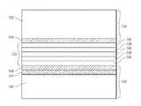
- the VCSELcomprises an active region including one or more quantum wells, wherein the active region comprises a high Al confinement region, the high Al being about >80% or more, an oxide layer comprising an aperture disposed near the active region, wherein vertically the center of the oxide layer is about 3 ⁇ 4 wave optical thickness from the center of the quantum wells, an intermediate region between the active region and the oxide layer, the intermediate region comprising a direct bandgap material with radiative lifetimes that are less than non-radiative lifetimes, and a spacer region, the spacer region comprising an extra mirror period, wherein the extra mirror period comprises low Al and is configured to trap minority carriers to allow them to recombine radiatively in the intermediate region.
- the high aluminum content regions 142 and 144act as an intermediate region or layer between the oxide layer 125 and the spacer regions or layers 148 and 150 .
- the high aluminum content regions 142 and 144may comprise a direct bandgap material with radiative lifetimes that are less than non-radiative lifetimes.
- the spacer regions 148 and 150may combine with the high aluminum content regions 142 and 144 respectively to form an extra mirror period such as the mirror periods 143 .
- the extra mirror periodcomprises low Al and is configured to trap minority carriers to allow them to recombine radiatively in the high aluminum content regions 142 and 144 .
- AlInGaAs quantum wells in 850 nm VCSELswere used to compensate for reductions in band gap. Dimensions for such quantum wells may be about 50 A with 4.8% indium. For narrower quantum wells, even more indium may be beneficial. Generally, as the quantum wells widen the required indium goes down reducing the benefit. As the quantum wells narrow the benefit increases with increased indium, but the wavelength control of the quantum wells becomes difficult as the gain wavelength becomes very strongly dependent on the quantum well width.
- the distance of the quantum wells to the closest Si doped layershould be at least about 26 nm and the silicon dopant in the layers should be about ⁇ 2 ⁇ 10 18 /cm3 and preferably 1 ⁇ 10 18 /cm3. Any extra dopants of any kind diffusing towards the quantum well will cause this problem, so the structure is designed to minimize this by having sufficient spacing between the dopants and the quantum wells.
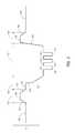
- the oxide layer 125 interfacerepresents a surface which has traps in the band gap.
- Sub-energy band gap lightsuch as extremely intense laser light can be absorbed by these traps, releasing minority carriers which can recombine non-radiatively causing the drift of dislocations from the oxide layer as previously discussed.
- the principles of the present inventionprovide embodiments that minimize this problem by placing the oxide layer 125 at a null of the standing optical field 125 and by keeping the oxide thin and having a sharp point at the tip.
- oxide layer 125includes an oxide that is thin and is tapered to a point.
- plot 500shows that oxide layer 125 is placed at the second null of standing optical wave.
- a 6-7 micron aperture devicewith around 50 ohms DC resistance can be made.
- the sheet resistance of the upper p-mirror for such a deviceis ⁇ 28 ohms. Some embodiments may be ⁇ 25 ohms. On particular embodiment is designed such that the sheet resistance of the upper p-mirror is about 20 ohms
Landscapes
- Physics & Mathematics (AREA)
- Condensed Matter Physics & Semiconductors (AREA)
- General Physics & Mathematics (AREA)
- Electromagnetism (AREA)
- Optics & Photonics (AREA)
- Semiconductor Lasers (AREA)
Abstract
Description
Claims (8)
Priority Applications (1)
| Application Number | Priority Date | Filing Date | Title |
|---|---|---|---|
| US12/340,286US8031752B1 (en) | 2007-04-16 | 2008-12-19 | VCSEL optimized for high speed data |
Applications Claiming Priority (3)
| Application Number | Priority Date | Filing Date | Title |
|---|---|---|---|
| US11/735,993US7829912B2 (en) | 2006-07-31 | 2007-04-16 | Efficient carrier injection in a semiconductor device |
| US1594907P | 2007-12-21 | 2007-12-21 | |
| US12/340,286US8031752B1 (en) | 2007-04-16 | 2008-12-19 | VCSEL optimized for high speed data |
Related Parent Applications (1)
| Application Number | Title | Priority Date | Filing Date |
|---|---|---|---|
| US11/735,993Continuation-In-PartUS7829912B2 (en) | 2004-08-31 | 2007-04-16 | Efficient carrier injection in a semiconductor device |
Publications (1)
| Publication Number | Publication Date |
|---|---|
| US8031752B1true US8031752B1 (en) | 2011-10-04 |
Family
ID=44676780
Family Applications (1)
| Application Number | Title | Priority Date | Filing Date |
|---|---|---|---|
| US12/340,286Active2028-02-18US8031752B1 (en) | 2007-04-16 | 2008-12-19 | VCSEL optimized for high speed data |
Country Status (1)
| Country | Link |
|---|---|
| US (1) | US8031752B1 (en) |
Cited By (11)
| Publication number | Priority date | Publication date | Assignee | Title |
|---|---|---|---|---|
| CN104106185A (en)* | 2012-03-02 | 2014-10-15 | 株式会社村田制作所 | Vertical-cavity surface-emitting laser |
| US20170214218A1 (en)* | 2014-09-22 | 2017-07-27 | Hewlett Packard Enterprise Development Lp | Single mode vertical-cavity surface-emitting laser |
| US10008826B1 (en) | 2015-05-01 | 2018-06-26 | Sae Magnetics (H.K.) Ltd. | Surface-emitting semiconductor laser |
| US20190214788A1 (en)* | 2018-01-09 | 2019-07-11 | Lg Innotek Co., Ltd. | Surface-emitting laser device and light emitting device including the same |
| US10447011B2 (en) | 2014-09-22 | 2019-10-15 | Hewlett Packard Enterprise Development Lp | Single mode vertical-cavity surface-emitting laser |
| KR20200000196A (en)* | 2018-06-22 | 2020-01-02 | 엘지이노텍 주식회사 | A surface-emitting laser device and light emitting device including the same |
| CN111279563A (en)* | 2017-09-18 | 2020-06-12 | 菲尼萨公司 | VCSEL with elliptical aperture with reduced RIN |
| US10707650B2 (en) | 2016-03-04 | 2020-07-07 | Princeton Optronics, Inc. | High-speed VCSEL device |
| US11099393B2 (en)* | 2019-11-22 | 2021-08-24 | Facebook Technologies, Llc | Surface emitting light source with lateral variant refractive index profile |
| US11749964B2 (en) | 2020-06-24 | 2023-09-05 | Meta Platforms Technologies, Llc | Monolithic light source with integrated optics based on nonlinear frequency conversion |
| WO2023171150A1 (en)* | 2022-03-11 | 2023-09-14 | ソニーセミコンダクタソリューションズ株式会社 | Vertical resonator surface emission laser |
Citations (138)
| Publication number | Priority date | Publication date | Assignee | Title |
|---|---|---|---|---|
| US4317085A (en) | 1979-09-12 | 1982-02-23 | Xerox Corporation | Channeled mesa laser |
| US4466694A (en) | 1978-06-15 | 1984-08-21 | Her Majesty The Queen In Right Of Canada, As Represented By The Minister Of National Defence Of Her Majesty's Canadian Government | Wavelength selective optical coupler |
| US4660207A (en) | 1984-11-21 | 1987-04-21 | Northern Telecom Limited | Surface-emitting light emitting device |
| US4675058A (en) | 1983-12-14 | 1987-06-23 | Honeywell Inc. | Method of manufacturing a high-bandwidth, high radiance, surface emitting LED |
| EP0288184A2 (en) | 1987-04-21 | 1988-10-26 | Gec-Marconi Limited | Semiconductor diode laser array |
| US4784722A (en) | 1985-01-22 | 1988-11-15 | Massachusetts Institute Of Technology | Method forming surface emitting diode laser |
| US4882734A (en) | 1988-03-09 | 1989-11-21 | Xerox Corporation | Quantum well heterostructure lasers with low current density threshold and higher TO values |
| US4885592A (en) | 1987-12-28 | 1989-12-05 | Kofol J Stephen | Electronically steerable antenna |
| US4901327A (en) | 1988-10-24 | 1990-02-13 | General Dynamics Corporation, Electronics Division | Transverse injection surface emitting laser |
| US4943970A (en) | 1988-10-24 | 1990-07-24 | General Dynamics Corporation, Electronics Division | Surface emitting laser |
| US4956844A (en) | 1989-03-17 | 1990-09-11 | Massachusetts Institute Of Technology | Two-dimensional surface-emitting laser array |
| US5031187A (en) | 1990-02-14 | 1991-07-09 | Bell Communications Research, Inc. | Planar array of vertical-cavity, surface-emitting lasers |
| US5052016A (en) | 1990-05-18 | 1991-09-24 | University Of New Mexico | Resonant-periodic-gain distributed-feedback surface-emitting semiconductor laser |
| US5056098A (en) | 1990-07-05 | 1991-10-08 | At&T Bell Laboratories | Vertical cavity laser with mirror having controllable reflectivity |
| US5062115A (en) | 1990-12-28 | 1991-10-29 | Xerox Corporation | High density, independently addressable, surface emitting semiconductor laser/light emitting diode arrays |
| US5068869A (en) | 1987-06-19 | 1991-11-26 | Lockheed Missiles & Space Company, Inc. | Surface-emitting laser diode |
| US5079774A (en) | 1990-12-27 | 1992-01-07 | International Business Machines Corporation | Polarization-tunable optoelectronic devices |
| US5115442A (en) | 1990-04-13 | 1992-05-19 | At&T Bell Laboratories | Top-emitting surface emitting laser structures |
| US5117469A (en) | 1991-02-01 | 1992-05-26 | Bell Communications Research, Inc. | Polarization-dependent and polarization-diversified opto-electronic devices using a strained quantum well |
| US5140605A (en) | 1991-06-27 | 1992-08-18 | Xerox Corporation | Thermally stabilized diode laser structure |
| US5157537A (en) | 1991-02-01 | 1992-10-20 | Yeda Research And Development Co., Ltd. | Distributed resonant cavity light beam modulator |
| US5158908A (en) | 1990-08-31 | 1992-10-27 | At&T Bell Laboratories | Distributed bragg reflectors and devices incorporating same |
| US5216263A (en) | 1990-11-29 | 1993-06-01 | Xerox Corporation | High density, independently addressable, surface emitting semiconductor laser-light emitting diode arrays |
| US5216680A (en) | 1991-07-11 | 1993-06-01 | Board Of Regents, The University Of Texas System | Optical guided-mode resonance filter |
| US5237581A (en) | 1990-11-14 | 1993-08-17 | Nec Corporation | Semiconductor multilayer reflector and light emitting device with the same |
| US5245622A (en) | 1992-05-07 | 1993-09-14 | Bandgap Technology Corporation | Vertical-cavity surface-emitting lasers with intra-cavity structures |
| US5258990A (en) | 1991-11-07 | 1993-11-02 | The United States Of America As Represented By The Secretary Of The United States Department Of Energy | Visible light surface emitting semiconductor laser |
| US5262360A (en) | 1990-12-31 | 1993-11-16 | The Board Of Trustees Of The University Of Illinois | AlGaAs native oxide |
| US5285466A (en) | 1992-05-20 | 1994-02-08 | Wisconsin Alumni Research Foundation | Feedback mechanism for vertical cavity surface emitting lasers |
| US5293392A (en) | 1992-07-31 | 1994-03-08 | Motorola, Inc. | Top emitting VCSEL with etch stop layer |
| US5317587A (en) | 1992-08-06 | 1994-05-31 | Motorola, Inc. | VCSEL with separate control of current distribution and optical mode |
| US5319660A (en) | 1992-05-29 | 1994-06-07 | Mcdonnell Douglas Corporation | Multi-quantum barrier laser |
| DE4240706A1 (en) | 1992-12-03 | 1994-06-09 | Siemens Ag | Surface emitting laser diode |
| US5325386A (en) | 1992-04-21 | 1994-06-28 | Bandgap Technology Corporation | Vertical-cavity surface emitting laser assay display system |
| US5331654A (en) | 1993-03-05 | 1994-07-19 | Photonics Research Incorporated | Polarized surface-emitting laser |
| US5331655A (en) | 1992-06-22 | 1994-07-19 | International Business Machines Corporation | Decoupled optic and electronic confinement laser diode |
| US5337183A (en) | 1991-02-01 | 1994-08-09 | Yeda Research And Development Co. Ltd. | Distributed resonant cavity light beam modulator |
| US5349599A (en) | 1990-03-29 | 1994-09-20 | Larkins Eric C | Bistable optical laser based on a heterostructure PNPN thyristor |
| US5351256A (en) | 1993-04-28 | 1994-09-27 | The United States Of America As Represented By The United States Department Of Energy | Electrically injected visible vertical cavity surface emitting laser diodes |
| US5359447A (en) | 1993-06-25 | 1994-10-25 | Hewlett-Packard Company | Optical communication with vertical-cavity surface-emitting laser operating in multiple transverse modes |
| US5359618A (en) | 1993-06-01 | 1994-10-25 | Motorola, Inc. | High efficiency VCSEL and method of fabrication |
| US5363397A (en) | 1992-10-29 | 1994-11-08 | Internatioal Business Machines Corporation | Integrated short cavity laser with bragg mirrors |
| US5373520A (en) | 1992-08-12 | 1994-12-13 | Fujitsu Limited | Surface emitting laser and method of manufacturing the same |
| US5386426A (en) | 1992-09-10 | 1995-01-31 | Hughes Aircraft Company | Narrow bandwidth laser array system |
| US5390209A (en) | 1994-01-05 | 1995-02-14 | At&T Corp. | Article comprising a semiconductor laser that is non-degenerate with regard to polarization |
| US5396508A (en) | 1992-09-22 | 1995-03-07 | Xerox Corporation | Polarization switchable quantum well laser |
| US5404373A (en) | 1991-11-08 | 1995-04-04 | University Of New Mexico | Electro-optical device |
| US5412680A (en) | 1994-03-18 | 1995-05-02 | Photonics Research Incorporated | Linear polarization of semiconductor laser |
| US5412678A (en) | 1992-09-22 | 1995-05-02 | Xerox Corporation | Multi-beam, orthogonally-polarized emitting monolithic quantum well lasers |
| US5416044A (en) | 1993-03-12 | 1995-05-16 | Matsushita Electric Industrial Co., Ltd. | Method for producing a surface-emitting laser |
| US5428634A (en) | 1992-11-05 | 1995-06-27 | The United States Of America As Represented By The United States Department Of Energy | Visible light emitting vertical cavity surface emitting lasers |
| US5438584A (en) | 1992-09-22 | 1995-08-01 | Xerox Corporation | Dual polarization laser diode with quaternary material system |
| US5446754A (en) | 1993-11-05 | 1995-08-29 | Photonics Research Incorporated | Phased array semiconductor laser |
| US5465263A (en) | 1992-12-12 | 1995-11-07 | Xerox Corporation | Monolithic, multiple wavelength, dual polarization laser diode arrays |
| US5475701A (en) | 1993-12-29 | 1995-12-12 | Honeywell Inc. | Integrated laser power monitor |
| US5493577A (en) | 1994-12-21 | 1996-02-20 | Sandia Corporation | Efficient semiconductor light-emitting device and method |
| US5497390A (en) | 1992-01-31 | 1996-03-05 | Nippon Telegraph And Telephone Corporation | Polarization mode switching semiconductor laser apparatus |
| US5513202A (en) | 1994-02-25 | 1996-04-30 | Matsushita Electric Industrial Co., Ltd. | Vertical-cavity surface-emitting semiconductor laser |
| US5530715A (en) | 1994-11-29 | 1996-06-25 | Motorola, Inc. | Vertical cavity surface emitting laser having continuous grading |
| US5557626A (en) | 1994-06-15 | 1996-09-17 | Motorola | Patterned mirror VCSEL with adjustable selective etch region |
| US5561683A (en) | 1994-01-27 | 1996-10-01 | Kwon; O'dae | Circular grating surface emitting laser diode |
| US5568499A (en) | 1995-04-07 | 1996-10-22 | Sandia Corporation | Optical device with low electrical and thermal resistance bragg reflectors |
| US5574738A (en) | 1995-06-07 | 1996-11-12 | Honeywell Inc. | Multi-gigahertz frequency-modulated vertical-cavity surface emitting laser |
| US5574744A (en) | 1995-02-03 | 1996-11-12 | Motorola | Optical coupler |
| US5581571A (en) | 1994-04-08 | 1996-12-03 | The Board Of Trustees Of The University Of Illinois | Semiconductor devices and methods |
| US5586131A (en) | 1993-12-10 | 1996-12-17 | Canon Kabushiki Kaisha | Oscillation polarization mode selective semiconductor laser, light source apparatus and optical communication system using the laser |
| US5590145A (en) | 1994-02-23 | 1996-12-31 | Canon Kabushiki Kaisha | Light-emitting apparatus capable of selecting polarization direction, optical communication system, and polarization modulation control method |
| US5598300A (en) | 1995-06-05 | 1997-01-28 | Board Of Regents, The University Of Texas System | Efficient bandpass reflection and transmission filters with low sidebands based on guided-mode resonance effects |
| US5606572A (en) | 1994-03-24 | 1997-02-25 | Vixel Corporation | Integration of laser with photodiode for feedback control |
| US5625729A (en) | 1994-08-12 | 1997-04-29 | Brown; Thomas G. | Optoelectronic device for coupling between an external optical wave and a local optical wave for optical modulators and detectors |
| EP0776076A1 (en) | 1995-11-21 | 1997-05-28 | Thomson-Csf | Optoelectronic quantum well device |
| US5646978A (en) | 1995-04-27 | 1997-07-08 | Lucent Technologies Inc. | Method and apparatus for providing interswitch handover in personal communication services systems |
| US5645462A (en) | 1991-10-08 | 1997-07-08 | Canon Kabushiki Kaisha | Electron-emitting device, and electron beam-generating apparatus and image-forming apparatus employing the device |
| US5648978A (en) | 1995-01-04 | 1997-07-15 | Canon Kabushiki Kaisha | Oscillation polarization mode selective semiconductor laser, modulation method therefor and optical communication system using the same |
| US5699373A (en) | 1994-03-17 | 1997-12-16 | Canon Kabushiki Kaisha | Oscillation polarization selective semiconductor laser and optical communication system using the same |
| US5712188A (en) | 1995-12-21 | 1998-01-27 | Electronics And Telecommunications Research Institute | Fabrication method of polarization-controlled surface-emitting laser diode using tilted-cavity |
| US5724374A (en) | 1996-08-19 | 1998-03-03 | Picolight Incorporated | Aperture comprising an oxidized region and a semiconductor material |
| US5727013A (en) | 1995-10-27 | 1998-03-10 | Wisconsin Alumni Research Foundation | Single lobe surface emitting complex coupled distributed feedback semiconductor laser |
| US5726805A (en) | 1996-06-25 | 1998-03-10 | Sandia Corporation | Optical filter including a sub-wavelength periodic structure and method of making |
| US5727014A (en) | 1995-10-31 | 1998-03-10 | Hewlett-Packard Company | Vertical-cavity surface-emitting laser generating light with a defined direction of polarization |
| US5745515A (en) | 1996-07-18 | 1998-04-28 | Honeywell Inc. | Self-limiting intrinsically eye-safe laser utilizing an increasing absorption layer |
| US5774487A (en) | 1996-10-16 | 1998-06-30 | Honeywell Inc. | Filamented multi-wavelength vertical-cavity surface emitting laser |
| US5778018A (en) | 1994-10-13 | 1998-07-07 | Nec Corporation | VCSELs (vertical-cavity surface emitting lasers) and VCSEL-based devices |
| US5784399A (en) | 1996-12-19 | 1998-07-21 | Xerox Corporation | Polarization mode selection by distributed Bragg reflector in a quantum well laser |
| US5828684A (en) | 1995-12-29 | 1998-10-27 | Xerox Corporation | Dual polarization quantum well laser in the 200 to 600 nanometers range |
| US5838705A (en) | 1996-11-04 | 1998-11-17 | Motorola, Inc. | Light emitting device having a defect inhibition layer |
| US5838715A (en) | 1996-06-20 | 1998-11-17 | Hewlett-Packard Company | High intensity single-mode VCSELs |
| US5896408A (en) | 1997-08-15 | 1999-04-20 | Hewlett-Packard Company | Near planar native-oxide VCSEL devices and arrays using converging oxide ringlets |
| US5901166A (en) | 1994-02-18 | 1999-05-04 | Canon Kabushiki Kaisha | Oscillation polarization mode selective semiconductor laser, light transmitter and optical communication system using the laser |
| US5903590A (en) | 1996-05-20 | 1999-05-11 | Sandia Corporation | Vertical-cavity surface-emitting laser device |
| US5903589A (en) | 1995-12-18 | 1999-05-11 | Picolight, Incorporated | Oxidizable semiconductor device having cavities which allow for improved oxidation of the semiconductor device |
| US5903588A (en) | 1997-03-06 | 1999-05-11 | Honeywell Inc. | Laser with a selectively changed current confining layer |
| US5908408A (en) | 1996-09-13 | 1999-06-01 | Mcgary; R. Kern | Non-reusable retractable safety syringe |
| US5940422A (en) | 1996-06-28 | 1999-08-17 | Honeywell Inc. | Laser with an improved mode control |
| US5953362A (en) | 1997-12-15 | 1999-09-14 | Pamulapati; Jagadeesh | Strain induce control of polarization states in vertical cavity surface emitting lasers and method of making same |
| US5959307A (en) | 1995-11-06 | 1999-09-28 | Nichia Chemical Industries Ltd. | Nitride semiconductor device |
| US5978401A (en) | 1995-10-25 | 1999-11-02 | Honeywell Inc. | Monolithic vertical cavity surface emitting laser and resonant cavity photodetector transceiver |
| US5978408A (en) | 1997-02-07 | 1999-11-02 | Xerox Corporation | Highly compact vertical cavity surface emitting lasers |
| US5995531A (en) | 1997-11-04 | 1999-11-30 | Motorola, Inc. | VCSEL having polarization control and method of making same |
| US6002705A (en) | 1997-12-03 | 1999-12-14 | Xerox Corporation | Wavelength and polarization multiplexed vertical cavity surface emitting lasers |
| US6008675A (en) | 1996-07-31 | 1999-12-28 | Canon Kabushiki Kaisha | Polarization-mode selective semiconductor laser with a bending channel stripe, apparatus including the same and optical communication system using the same |
| US6043104A (en) | 1996-08-28 | 2000-03-28 | Canon Kabushiki Kaisha | Fabrication method of a polarization selective semiconductor laser |
| US6055262A (en) | 1997-06-11 | 2000-04-25 | Honeywell Inc. | Resonant reflector for improved optoelectronic device performance and enhanced applicability |
| US6078601A (en) | 1997-03-07 | 2000-06-20 | Smith; David F. | Method for controlling the operation of a laser |
| JP2000294872A (en) | 1999-04-01 | 2000-10-20 | Fuji Xerox Co Ltd | Surface emitting laser and surface emitting laser array |
| US6144682A (en) | 1998-10-29 | 2000-11-07 | Xerox Corporation | Spatial absorptive and phase shift filter layer to reduce modal reflectivity for higher order modes in a vertical cavity surface emitting laser |
| US6154480A (en) | 1997-10-02 | 2000-11-28 | Board Of Regents, The University Of Texas System | Vertical-cavity laser and laser array incorporating guided-mode resonance effects and method for making the same |
| US6185241B1 (en) | 1998-10-29 | 2001-02-06 | Xerox Corporation | Metal spatial filter to enhance model reflectivity in a vertical cavity surface emitting laser |
| US6191890B1 (en) | 1996-03-29 | 2001-02-20 | Interuniversitair Micro-Elektronica Centrum Vzw | Optical system with a dielectric subwavelength structure having high reflectivity and polarization selectivity |
| US6212312B1 (en) | 1999-09-17 | 2001-04-03 | U.T. Battelle, Llc | Optical multiplexer/demultiplexer using resonant grating filters |
| US6238944B1 (en) | 1999-12-21 | 2001-05-29 | Xerox Corporation | Buried heterostructure vertical-cavity surface-emitting laser diodes using impurity induced layer disordering (IILD) via a buried impurity source |
| US6266357B1 (en) | 1998-09-01 | 2001-07-24 | The United States Of America As Represented By The Secretary Of The Air Force | Microcavity surface emitting laser |
| US6317446B1 (en) | 1998-03-27 | 2001-11-13 | Siemens Aktiengesellschaft | Vertical resonator laser diode and method for producing it |
| US6320893B1 (en) | 1997-08-15 | 2001-11-20 | Fuji Xerox Co., Ltd. | Surface emitting semiconductor laser |
| US20010043629A1 (en) | 1998-04-14 | 2001-11-22 | Decai Sun | Opto-electronic devices with multiple oxide apertures |
| US20010050934A1 (en) | 2000-05-31 | 2001-12-13 | Choquette Kent D. | Long wavelength vertical cavity surface emitting laser |
| US6372533B2 (en) | 1998-11-05 | 2002-04-16 | Gore Enterprise Holdings, Inc. | Method of making a semiconductor device with aligned oxide apertures and contact to an intervening layer |
| US6411638B1 (en) | 1999-08-31 | 2002-06-25 | Honeywell Inc. | Coupled cavity anti-guided vertical-cavity surface-emitting laser |
| US20020101899A1 (en) | 2000-11-28 | 2002-08-01 | Noriyuki Yokouchi | Vertical cavity surface emitting laser device |
| JP2002217491A (en) | 2001-01-17 | 2002-08-02 | Canon Inc | Surface emitting laser device, manufacturing method thereof, and driving method thereof |
| US20020154675A1 (en) | 2001-04-23 | 2002-10-24 | Qing Deng | Reliability-enhancing layers for vertical cavity surface emitting lasers |
| US6545335B1 (en) | 1999-12-27 | 2003-04-08 | Xerox Corporation | Structure and method for electrical isolation of optoelectronic integrated circuits |
| US6570905B1 (en) | 2000-11-02 | 2003-05-27 | U-L-M Photonics Gmbh | Vertical cavity surface emitting laser with reduced parasitic capacitance |
| US20030123514A1 (en) | 2001-12-28 | 2003-07-03 | Cox James A. | Vertical cavity surface emitting laser having a gain guide aperture interior to an oxide confinement layer |
| US20030123513A1 (en) | 2001-12-28 | 2003-07-03 | Villareal Samuel S. | Assymmetric distributed bragg reflector for vertical cavity surface emitting lasers |
| WO2004033557A1 (en) | 2002-10-04 | 2004-04-22 | Finisar Corporation | Method and apparatus for compensating a photo-detector |
| US6727520B2 (en) | 2000-12-29 | 2004-04-27 | Honeywell International Inc. | Spatially modulated reflector for an optoelectronic device |
| US20040081215A1 (en) | 2002-10-28 | 2004-04-29 | Honeywell International Inc. | Distributed bragg reflector for optoelectronic device |
| US6782027B2 (en) | 2000-12-29 | 2004-08-24 | Finisar Corporation | Resonant reflector for use with optoelectronic devices |
| US6829283B2 (en) | 2001-09-26 | 2004-12-07 | Infineon Technologies Ag | Semiconductor laser |
| US20050031011A1 (en) | 2000-11-28 | 2005-02-10 | Biard James R. | Electron affinity engineered VCSELs |
| US20050127391A1 (en) | 2001-11-05 | 2005-06-16 | Nichia Corporation | Semiconductor element |
| US7026653B2 (en) | 2004-01-27 | 2006-04-11 | Lumileds Lighting, U.S., Llc | Semiconductor light emitting devices including current spreading layers |
| US20060093010A1 (en)* | 2001-02-26 | 2006-05-04 | Takuro Sekiya | Surface-emission laser diode operable in the wavelength band of 1.1-1.7 um and optical telecommunication system using such a laser diode |
| US20060268954A1 (en) | 2004-08-31 | 2006-11-30 | Johnson Ralph H | Light emitting semiconductor device having an electrical confinement barrier near the active region |
| US20090003399A1 (en)* | 2007-06-26 | 2009-01-01 | Taylor Geoff W | Integrated Circuit Employing Low Loss Spot-Size Converter |
| US20090115346A1 (en) | 2006-02-27 | 2009-05-07 | The Board Of Trustees Of The University Of Illinois | PNP light emitting transistor and method |
| US7596165B2 (en) | 2004-08-31 | 2009-09-29 | Finisar Corporation | Distributed Bragg Reflector for optoelectronic device |
- 2008
- 2008-12-19USUS12/340,286patent/US8031752B1/enactiveActive
Patent Citations (156)
| Publication number | Priority date | Publication date | Assignee | Title |
|---|---|---|---|---|
| US4466694A (en) | 1978-06-15 | 1984-08-21 | Her Majesty The Queen In Right Of Canada, As Represented By The Minister Of National Defence Of Her Majesty's Canadian Government | Wavelength selective optical coupler |
| US4317085A (en) | 1979-09-12 | 1982-02-23 | Xerox Corporation | Channeled mesa laser |
| US4675058A (en) | 1983-12-14 | 1987-06-23 | Honeywell Inc. | Method of manufacturing a high-bandwidth, high radiance, surface emitting LED |
| US4660207A (en) | 1984-11-21 | 1987-04-21 | Northern Telecom Limited | Surface-emitting light emitting device |
| US4784722A (en) | 1985-01-22 | 1988-11-15 | Massachusetts Institute Of Technology | Method forming surface emitting diode laser |
| EP0288184A2 (en) | 1987-04-21 | 1988-10-26 | Gec-Marconi Limited | Semiconductor diode laser array |
| US5068869A (en) | 1987-06-19 | 1991-11-26 | Lockheed Missiles & Space Company, Inc. | Surface-emitting laser diode |
| US4885592A (en) | 1987-12-28 | 1989-12-05 | Kofol J Stephen | Electronically steerable antenna |
| US4882734A (en) | 1988-03-09 | 1989-11-21 | Xerox Corporation | Quantum well heterostructure lasers with low current density threshold and higher TO values |
| US4901327A (en) | 1988-10-24 | 1990-02-13 | General Dynamics Corporation, Electronics Division | Transverse injection surface emitting laser |
| US4943970A (en) | 1988-10-24 | 1990-07-24 | General Dynamics Corporation, Electronics Division | Surface emitting laser |
| US4956844A (en) | 1989-03-17 | 1990-09-11 | Massachusetts Institute Of Technology | Two-dimensional surface-emitting laser array |
| US5031187A (en) | 1990-02-14 | 1991-07-09 | Bell Communications Research, Inc. | Planar array of vertical-cavity, surface-emitting lasers |
| US5349599A (en) | 1990-03-29 | 1994-09-20 | Larkins Eric C | Bistable optical laser based on a heterostructure PNPN thyristor |
| US5115442A (en) | 1990-04-13 | 1992-05-19 | At&T Bell Laboratories | Top-emitting surface emitting laser structures |
| US5052016A (en) | 1990-05-18 | 1991-09-24 | University Of New Mexico | Resonant-periodic-gain distributed-feedback surface-emitting semiconductor laser |
| US5056098A (en) | 1990-07-05 | 1991-10-08 | At&T Bell Laboratories | Vertical cavity laser with mirror having controllable reflectivity |
| US5158908A (en) | 1990-08-31 | 1992-10-27 | At&T Bell Laboratories | Distributed bragg reflectors and devices incorporating same |
| US5237581A (en) | 1990-11-14 | 1993-08-17 | Nec Corporation | Semiconductor multilayer reflector and light emitting device with the same |
| US5317170A (en) | 1990-11-29 | 1994-05-31 | Xerox Corporation | High density, independently addressable, surface emitting semiconductor laser/light emitting diode arrays without a substrate |
| US5216263A (en) | 1990-11-29 | 1993-06-01 | Xerox Corporation | High density, independently addressable, surface emitting semiconductor laser-light emitting diode arrays |
| US5079774A (en) | 1990-12-27 | 1992-01-07 | International Business Machines Corporation | Polarization-tunable optoelectronic devices |
| US5062115A (en) | 1990-12-28 | 1991-10-29 | Xerox Corporation | High density, independently addressable, surface emitting semiconductor laser/light emitting diode arrays |
| US5337074A (en) | 1990-12-28 | 1994-08-09 | Xerox Corporation | Opto-electronic line printer having a high density, independently addressable, surface emitting semiconductor laser/light emitting diode array |
| US5696023A (en) | 1990-12-31 | 1997-12-09 | The Board Of Trustees Of The University Of Illinois | Method for making aluminum gallium arsenide semiconductor device with native oxide layer |
| US5567980A (en) | 1990-12-31 | 1996-10-22 | The Board Of Trustees Of The University Of Illinois | Native oxide of an aluminum-bearing group III-V semiconductor |
| US5373522A (en) | 1990-12-31 | 1994-12-13 | The Board Of Trustees Of The University Of Illinois | Semiconductor devices with native aluminum oxide regions |
| US5262360A (en) | 1990-12-31 | 1993-11-16 | The Board Of Trustees Of The University Of Illinois | AlGaAs native oxide |
| US5157537A (en) | 1991-02-01 | 1992-10-20 | Yeda Research And Development Co., Ltd. | Distributed resonant cavity light beam modulator |
| US5337183A (en) | 1991-02-01 | 1994-08-09 | Yeda Research And Development Co. Ltd. | Distributed resonant cavity light beam modulator |
| US5117469A (en) | 1991-02-01 | 1992-05-26 | Bell Communications Research, Inc. | Polarization-dependent and polarization-diversified opto-electronic devices using a strained quantum well |
| US5140605A (en) | 1991-06-27 | 1992-08-18 | Xerox Corporation | Thermally stabilized diode laser structure |
| US5216680A (en) | 1991-07-11 | 1993-06-01 | Board Of Regents, The University Of Texas System | Optical guided-mode resonance filter |
| US5645462A (en) | 1991-10-08 | 1997-07-08 | Canon Kabushiki Kaisha | Electron-emitting device, and electron beam-generating apparatus and image-forming apparatus employing the device |
| US5258990A (en) | 1991-11-07 | 1993-11-02 | The United States Of America As Represented By The Secretary Of The United States Department Of Energy | Visible light surface emitting semiconductor laser |
| US5642376A (en) | 1991-11-07 | 1997-06-24 | Vixel Corporation | Visible light surface emitting semiconductor laser |
| US5404373A (en) | 1991-11-08 | 1995-04-04 | University Of New Mexico | Electro-optical device |
| US5497390A (en) | 1992-01-31 | 1996-03-05 | Nippon Telegraph And Telephone Corporation | Polarization mode switching semiconductor laser apparatus |
| US5325386A (en) | 1992-04-21 | 1994-06-28 | Bandgap Technology Corporation | Vertical-cavity surface emitting laser assay display system |
| US5245622A (en) | 1992-05-07 | 1993-09-14 | Bandgap Technology Corporation | Vertical-cavity surface-emitting lasers with intra-cavity structures |
| US5285466A (en) | 1992-05-20 | 1994-02-08 | Wisconsin Alumni Research Foundation | Feedback mechanism for vertical cavity surface emitting lasers |
| US5319660A (en) | 1992-05-29 | 1994-06-07 | Mcdonnell Douglas Corporation | Multi-quantum barrier laser |
| US5331655A (en) | 1992-06-22 | 1994-07-19 | International Business Machines Corporation | Decoupled optic and electronic confinement laser diode |
| US5293392A (en) | 1992-07-31 | 1994-03-08 | Motorola, Inc. | Top emitting VCSEL with etch stop layer |
| US5317587A (en) | 1992-08-06 | 1994-05-31 | Motorola, Inc. | VCSEL with separate control of current distribution and optical mode |
| US5373520A (en) | 1992-08-12 | 1994-12-13 | Fujitsu Limited | Surface emitting laser and method of manufacturing the same |
| US5386426A (en) | 1992-09-10 | 1995-01-31 | Hughes Aircraft Company | Narrow bandwidth laser array system |
| US5412678A (en) | 1992-09-22 | 1995-05-02 | Xerox Corporation | Multi-beam, orthogonally-polarized emitting monolithic quantum well lasers |
| US5396508A (en) | 1992-09-22 | 1995-03-07 | Xerox Corporation | Polarization switchable quantum well laser |
| US5438584A (en) | 1992-09-22 | 1995-08-01 | Xerox Corporation | Dual polarization laser diode with quaternary material system |
| US5363397A (en) | 1992-10-29 | 1994-11-08 | Internatioal Business Machines Corporation | Integrated short cavity laser with bragg mirrors |
| US5428634A (en) | 1992-11-05 | 1995-06-27 | The United States Of America As Represented By The United States Department Of Energy | Visible light emitting vertical cavity surface emitting lasers |
| DE4240706A1 (en) | 1992-12-03 | 1994-06-09 | Siemens Ag | Surface emitting laser diode |
| US5555255A (en) | 1992-12-03 | 1996-09-10 | Siemens Aktiengesellschaft | Surface-emitting laser diode |
| US5465263A (en) | 1992-12-12 | 1995-11-07 | Xerox Corporation | Monolithic, multiple wavelength, dual polarization laser diode arrays |
| US5331654A (en) | 1993-03-05 | 1994-07-19 | Photonics Research Incorporated | Polarized surface-emitting laser |
| US5416044A (en) | 1993-03-12 | 1995-05-16 | Matsushita Electric Industrial Co., Ltd. | Method for producing a surface-emitting laser |
| US5351256A (en) | 1993-04-28 | 1994-09-27 | The United States Of America As Represented By The United States Department Of Energy | Electrically injected visible vertical cavity surface emitting laser diodes |
| US5359618A (en) | 1993-06-01 | 1994-10-25 | Motorola, Inc. | High efficiency VCSEL and method of fabrication |
| US5359447A (en) | 1993-06-25 | 1994-10-25 | Hewlett-Packard Company | Optical communication with vertical-cavity surface-emitting laser operating in multiple transverse modes |
| US5446754A (en) | 1993-11-05 | 1995-08-29 | Photonics Research Incorporated | Phased array semiconductor laser |
| US5586131A (en) | 1993-12-10 | 1996-12-17 | Canon Kabushiki Kaisha | Oscillation polarization mode selective semiconductor laser, light source apparatus and optical communication system using the laser |
| US5475701A (en) | 1993-12-29 | 1995-12-12 | Honeywell Inc. | Integrated laser power monitor |
| US5390209A (en) | 1994-01-05 | 1995-02-14 | At&T Corp. | Article comprising a semiconductor laser that is non-degenerate with regard to polarization |
| US5561683A (en) | 1994-01-27 | 1996-10-01 | Kwon; O'dae | Circular grating surface emitting laser diode |
| US5901166A (en) | 1994-02-18 | 1999-05-04 | Canon Kabushiki Kaisha | Oscillation polarization mode selective semiconductor laser, light transmitter and optical communication system using the laser |
| US5590145A (en) | 1994-02-23 | 1996-12-31 | Canon Kabushiki Kaisha | Light-emitting apparatus capable of selecting polarization direction, optical communication system, and polarization modulation control method |
| US5513202A (en) | 1994-02-25 | 1996-04-30 | Matsushita Electric Industrial Co., Ltd. | Vertical-cavity surface-emitting semiconductor laser |
| US5699373A (en) | 1994-03-17 | 1997-12-16 | Canon Kabushiki Kaisha | Oscillation polarization selective semiconductor laser and optical communication system using the same |
| US5412680A (en) | 1994-03-18 | 1995-05-02 | Photonics Research Incorporated | Linear polarization of semiconductor laser |
| US5606572A (en) | 1994-03-24 | 1997-02-25 | Vixel Corporation | Integration of laser with photodiode for feedback control |
| US5581571A (en) | 1994-04-08 | 1996-12-03 | The Board Of Trustees Of The University Of Illinois | Semiconductor devices and methods |
| US5557626A (en) | 1994-06-15 | 1996-09-17 | Motorola | Patterned mirror VCSEL with adjustable selective etch region |
| US5625729A (en) | 1994-08-12 | 1997-04-29 | Brown; Thomas G. | Optoelectronic device for coupling between an external optical wave and a local optical wave for optical modulators and detectors |
| US5778018A (en) | 1994-10-13 | 1998-07-07 | Nec Corporation | VCSELs (vertical-cavity surface emitting lasers) and VCSEL-based devices |
| US5530715A (en) | 1994-11-29 | 1996-06-25 | Motorola, Inc. | Vertical cavity surface emitting laser having continuous grading |
| US5493577A (en) | 1994-12-21 | 1996-02-20 | Sandia Corporation | Efficient semiconductor light-emitting device and method |
| US5648978A (en) | 1995-01-04 | 1997-07-15 | Canon Kabushiki Kaisha | Oscillation polarization mode selective semiconductor laser, modulation method therefor and optical communication system using the same |
| US5574744A (en) | 1995-02-03 | 1996-11-12 | Motorola | Optical coupler |
| US5568499A (en) | 1995-04-07 | 1996-10-22 | Sandia Corporation | Optical device with low electrical and thermal resistance bragg reflectors |
| US5646978A (en) | 1995-04-27 | 1997-07-08 | Lucent Technologies Inc. | Method and apparatus for providing interswitch handover in personal communication services systems |
| US5598300A (en) | 1995-06-05 | 1997-01-28 | Board Of Regents, The University Of Texas System | Efficient bandpass reflection and transmission filters with low sidebands based on guided-mode resonance effects |
| US5574738A (en) | 1995-06-07 | 1996-11-12 | Honeywell Inc. | Multi-gigahertz frequency-modulated vertical-cavity surface emitting laser |
| US5978401A (en) | 1995-10-25 | 1999-11-02 | Honeywell Inc. | Monolithic vertical cavity surface emitting laser and resonant cavity photodetector transceiver |
| US5727013A (en) | 1995-10-27 | 1998-03-10 | Wisconsin Alumni Research Foundation | Single lobe surface emitting complex coupled distributed feedback semiconductor laser |
| US5727014A (en) | 1995-10-31 | 1998-03-10 | Hewlett-Packard Company | Vertical-cavity surface-emitting laser generating light with a defined direction of polarization |
| US5959307A (en) | 1995-11-06 | 1999-09-28 | Nichia Chemical Industries Ltd. | Nitride semiconductor device |
| US5818066A (en) | 1995-11-21 | 1998-10-06 | Thomson-Csf | Optoelectronic quantum well device having an optical resonant cavity and sustaining inter subband transitions |
| EP0776076A1 (en) | 1995-11-21 | 1997-05-28 | Thomson-Csf | Optoelectronic quantum well device |
| US6269109B1 (en) | 1995-12-18 | 2001-07-31 | Picolight Incorporated | Conductive element with lateral oxidation barrier |
| US6014395A (en) | 1995-12-18 | 2000-01-11 | Picolight Incorporated | Oxidizable semiconductor device having cavities which allow for improved oxidation of the semiconductor device |
| US5903589A (en) | 1995-12-18 | 1999-05-11 | Picolight, Incorporated | Oxidizable semiconductor device having cavities which allow for improved oxidation of the semiconductor device |
| US6459713B2 (en) | 1995-12-18 | 2002-10-01 | Picolight Incorporated | Conductive element with lateral oxidation barrier |
| US5712188A (en) | 1995-12-21 | 1998-01-27 | Electronics And Telecommunications Research Institute | Fabrication method of polarization-controlled surface-emitting laser diode using tilted-cavity |
| US5828684A (en) | 1995-12-29 | 1998-10-27 | Xerox Corporation | Dual polarization quantum well laser in the 200 to 600 nanometers range |
| US6191890B1 (en) | 1996-03-29 | 2001-02-20 | Interuniversitair Micro-Elektronica Centrum Vzw | Optical system with a dielectric subwavelength structure having high reflectivity and polarization selectivity |
| US5903590A (en) | 1996-05-20 | 1999-05-11 | Sandia Corporation | Vertical-cavity surface-emitting laser device |
| US5838715A (en) | 1996-06-20 | 1998-11-17 | Hewlett-Packard Company | High intensity single-mode VCSELs |
| US5726805A (en) | 1996-06-25 | 1998-03-10 | Sandia Corporation | Optical filter including a sub-wavelength periodic structure and method of making |
| US5940422A (en) | 1996-06-28 | 1999-08-17 | Honeywell Inc. | Laser with an improved mode control |
| US5745515A (en) | 1996-07-18 | 1998-04-28 | Honeywell Inc. | Self-limiting intrinsically eye-safe laser utilizing an increasing absorption layer |
| US6008675A (en) | 1996-07-31 | 1999-12-28 | Canon Kabushiki Kaisha | Polarization-mode selective semiconductor laser with a bending channel stripe, apparatus including the same and optical communication system using the same |
| US5724374A (en) | 1996-08-19 | 1998-03-03 | Picolight Incorporated | Aperture comprising an oxidized region and a semiconductor material |
| US6043104A (en) | 1996-08-28 | 2000-03-28 | Canon Kabushiki Kaisha | Fabrication method of a polarization selective semiconductor laser |
| US5908408A (en) | 1996-09-13 | 1999-06-01 | Mcgary; R. Kern | Non-reusable retractable safety syringe |
| US5774487A (en) | 1996-10-16 | 1998-06-30 | Honeywell Inc. | Filamented multi-wavelength vertical-cavity surface emitting laser |
| US5838705A (en) | 1996-11-04 | 1998-11-17 | Motorola, Inc. | Light emitting device having a defect inhibition layer |
| US5784399A (en) | 1996-12-19 | 1998-07-21 | Xerox Corporation | Polarization mode selection by distributed Bragg reflector in a quantum well laser |
| US6297068B1 (en) | 1997-02-07 | 2001-10-02 | Xerox Corporation | Method for highly compact vertical cavity surface emitting lasers |
| US5978408A (en) | 1997-02-07 | 1999-11-02 | Xerox Corporation | Highly compact vertical cavity surface emitting lasers |
| US6208681B1 (en) | 1997-02-07 | 2001-03-27 | Xerox Corporation | Highly compact vertical cavity surface emitting lasers |
| US5903588A (en) | 1997-03-06 | 1999-05-11 | Honeywell Inc. | Laser with a selectively changed current confining layer |
| US6078601A (en) | 1997-03-07 | 2000-06-20 | Smith; David F. | Method for controlling the operation of a laser |
| US6055262A (en) | 1997-06-11 | 2000-04-25 | Honeywell Inc. | Resonant reflector for improved optoelectronic device performance and enhanced applicability |
| US6320893B1 (en) | 1997-08-15 | 2001-11-20 | Fuji Xerox Co., Ltd. | Surface emitting semiconductor laser |
| US5896408A (en) | 1997-08-15 | 1999-04-20 | Hewlett-Packard Company | Near planar native-oxide VCSEL devices and arrays using converging oxide ringlets |
| US6154480A (en) | 1997-10-02 | 2000-11-28 | Board Of Regents, The University Of Texas System | Vertical-cavity laser and laser array incorporating guided-mode resonance effects and method for making the same |
| US5995531A (en) | 1997-11-04 | 1999-11-30 | Motorola, Inc. | VCSEL having polarization control and method of making same |
| US6002705A (en) | 1997-12-03 | 1999-12-14 | Xerox Corporation | Wavelength and polarization multiplexed vertical cavity surface emitting lasers |
| US5953362A (en) | 1997-12-15 | 1999-09-14 | Pamulapati; Jagadeesh | Strain induce control of polarization states in vertical cavity surface emitting lasers and method of making same |
| US6317446B1 (en) | 1998-03-27 | 2001-11-13 | Siemens Aktiengesellschaft | Vertical resonator laser diode and method for producing it |
| US20010043629A1 (en) | 1998-04-14 | 2001-11-22 | Decai Sun | Opto-electronic devices with multiple oxide apertures |
| US6266357B1 (en) | 1998-09-01 | 2001-07-24 | The United States Of America As Represented By The Secretary Of The Air Force | Microcavity surface emitting laser |
| US6144682A (en) | 1998-10-29 | 2000-11-07 | Xerox Corporation | Spatial absorptive and phase shift filter layer to reduce modal reflectivity for higher order modes in a vertical cavity surface emitting laser |
| US6185241B1 (en) | 1998-10-29 | 2001-02-06 | Xerox Corporation | Metal spatial filter to enhance model reflectivity in a vertical cavity surface emitting laser |
| US6372533B2 (en) | 1998-11-05 | 2002-04-16 | Gore Enterprise Holdings, Inc. | Method of making a semiconductor device with aligned oxide apertures and contact to an intervening layer |
| JP2000294872A (en) | 1999-04-01 | 2000-10-20 | Fuji Xerox Co Ltd | Surface emitting laser and surface emitting laser array |
| US6411638B1 (en) | 1999-08-31 | 2002-06-25 | Honeywell Inc. | Coupled cavity anti-guided vertical-cavity surface-emitting laser |
| US6212312B1 (en) | 1999-09-17 | 2001-04-03 | U.T. Battelle, Llc | Optical multiplexer/demultiplexer using resonant grating filters |
| US6238944B1 (en) | 1999-12-21 | 2001-05-29 | Xerox Corporation | Buried heterostructure vertical-cavity surface-emitting laser diodes using impurity induced layer disordering (IILD) via a buried impurity source |
| US6545335B1 (en) | 1999-12-27 | 2003-04-08 | Xerox Corporation | Structure and method for electrical isolation of optoelectronic integrated circuits |
| US20010050934A1 (en) | 2000-05-31 | 2001-12-13 | Choquette Kent D. | Long wavelength vertical cavity surface emitting laser |
| US6570905B1 (en) | 2000-11-02 | 2003-05-27 | U-L-M Photonics Gmbh | Vertical cavity surface emitting laser with reduced parasitic capacitance |
| US20020101899A1 (en) | 2000-11-28 | 2002-08-01 | Noriyuki Yokouchi | Vertical cavity surface emitting laser device |
| US7065124B2 (en) | 2000-11-28 | 2006-06-20 | Finlsar Corporation | Electron affinity engineered VCSELs |
| US20050031011A1 (en) | 2000-11-28 | 2005-02-10 | Biard James R. | Electron affinity engineered VCSELs |
| US6700914B2 (en) | 2000-11-28 | 2004-03-02 | The Furukawa Electric Co., Ltd. | Vertical cavity surface emitting laser device |
| US6727520B2 (en) | 2000-12-29 | 2004-04-27 | Honeywell International Inc. | Spatially modulated reflector for an optoelectronic device |
| US6782027B2 (en) | 2000-12-29 | 2004-08-24 | Finisar Corporation | Resonant reflector for use with optoelectronic devices |
| JP2002217491A (en) | 2001-01-17 | 2002-08-02 | Canon Inc | Surface emitting laser device, manufacturing method thereof, and driving method thereof |
| US20060093010A1 (en)* | 2001-02-26 | 2006-05-04 | Takuro Sekiya | Surface-emission laser diode operable in the wavelength band of 1.1-1.7 um and optical telecommunication system using such a laser diode |
| US6628694B2 (en) | 2001-04-23 | 2003-09-30 | Agilent Technologies, Inc. | Reliability-enhancing layers for vertical cavity surface emitting lasers |
| US20020154675A1 (en) | 2001-04-23 | 2002-10-24 | Qing Deng | Reliability-enhancing layers for vertical cavity surface emitting lasers |
| US6829283B2 (en) | 2001-09-26 | 2004-12-07 | Infineon Technologies Ag | Semiconductor laser |
| US20050127391A1 (en) | 2001-11-05 | 2005-06-16 | Nichia Corporation | Semiconductor element |
| US20030123513A1 (en) | 2001-12-28 | 2003-07-03 | Villareal Samuel S. | Assymmetric distributed bragg reflector for vertical cavity surface emitting lasers |
| US20030123514A1 (en) | 2001-12-28 | 2003-07-03 | Cox James A. | Vertical cavity surface emitting laser having a gain guide aperture interior to an oxide confinement layer |
| WO2004033557A1 (en) | 2002-10-04 | 2004-04-22 | Finisar Corporation | Method and apparatus for compensating a photo-detector |
| US7251264B2 (en) | 2002-10-28 | 2007-07-31 | Finisar Corporation | Distributed bragg reflector for optoelectronic device |
| US6990135B2 (en) | 2002-10-28 | 2006-01-24 | Finisar Corporation | Distributed bragg reflector for optoelectronic device |
| US20040081215A1 (en) | 2002-10-28 | 2004-04-29 | Honeywell International Inc. | Distributed bragg reflector for optoelectronic device |
| US7026653B2 (en) | 2004-01-27 | 2006-04-11 | Lumileds Lighting, U.S., Llc | Semiconductor light emitting devices including current spreading layers |
| US20060268954A1 (en) | 2004-08-31 | 2006-11-30 | Johnson Ralph H | Light emitting semiconductor device having an electrical confinement barrier near the active region |
| US7596165B2 (en) | 2004-08-31 | 2009-09-29 | Finisar Corporation | Distributed Bragg Reflector for optoelectronic device |
| US20090115346A1 (en) | 2006-02-27 | 2009-05-07 | The Board Of Trustees Of The University Of Illinois | PNP light emitting transistor and method |
| US20090003399A1 (en)* | 2007-06-26 | 2009-01-01 | Taylor Geoff W | Integrated Circuit Employing Low Loss Spot-Size Converter |
Non-Patent Citations (105)
| Title |
|---|
| 1020057006453.00, Aug. 29, 2006, KR Office Action. |
| 3779187.8, Aug. 31, 2005, EP Office Action. |
| Banwell et al., "VCSE Laser Transmitters for Parallel Data Links", IEEE Journal of Quantum Electronics, vol. 29, No. 2, Feb. 1993, pp. 635-644. |
| Ben G. Streetman and Sanjay Jumar Banerjee, "Solid State Electronic Devices" Sixth Edition Prentice Hall, p. 228. |
| Bowers et al., "Fused Vertical Cavity Lasers With Oxide Aperture", Final report for MICRO project 96-042, Industrial Sponsor: Hewlett Packard, 4 pgs, 1996-97. |
| Catchmark et al., "High Temperature CW Operation of Vertical Cavity Top Surface-Emitting Lasers", CLEO 1993, p. 138. |
| Chang et al., "The Carrier Blocking Effect on 850nm InAlGaAs/AlGaAs Vertical-Cavity Surface-Emitting Lasers," Institute of Physics Publishing, Semiconductor Science and Technology, 21, (2006), pp. 1488-1494. |
| Chang et al., "Theoretical and Experimental Analysis on InAlGaAs/AlGaAs Active Region of 850-nm Vertical-Cavity Surface-Emitting Lasers," Journal of Lightwave Technology, vol. 24, No. 1, Jan. (2006). |
| Chemla et al., "Nonlinear Optical Properties of Semiconductor Quantum Wells", Optical Nonlinearities and Instabilities in Semiconductors, Academic Press, Inc., Copyright 1988, pp. 83-120. |
| Choa et al., "High-Speed Modulation of Vertical-Cavity Surface-Emitting Lasers", IEEE PhotonicsTechnology Letter, vol. 3, No. 8, Aug. 1991, pp. 697-699. |
| Choe, et al., "Lateral oxidation of AIAs layers at elevated water vapour pressure using a closed-chamber system," Letter to the Editor, Semiconductor Science Technology, 15, pp. L35-L38, Aug. 2000. |
| Choquette et al., "High Single Mode Operation from Hybrid Ion Implanted/Selectively Oxidized VCSELs", 2000 IEEE 17th International Semiconductor Laser Conference; Monterrey, CA, pp. 59-60. |
| Choquette et al., "Lithographically-Defined Gain Apertures Within Selectively Oxidized VCSELs", paper CtuL6, Conference on Lasers and Electro-Optics, San Francisco, California (2000). |
| Choquette, et al., "VCSELs in information systems: lOGbps−1 oxide VCSELs for data communication", Optics in Information Systems, vol. 12, No. 1, p. 5, SPIE International Technical Group Newsletter, Apr. 2001. |
| Choquette, et al., "VCSELs in information systems: lOGbps-1 oxide VCSELs for data communication", Optics in Information Systems, vol. 12, No. 1, p. 5, SPIE International Technical Group Newsletter, Apr. 2001. |
| Choquette, Kent D. et al., Design of Oxide Aperture Profile within Selectively Oxidized VCSELs, IEEE, Conference Proceedings, LEOS '98, 11th Annual Meeting, Orlando, Florida, Dec. 1-4, 1998, pp. 179-180. |
| Chua, et al, "Planar Laterally Oxidized Vertical-Cavity Lasers for Low-Threshold High-Density Top-Surface-Emitting Arrays," IEEE Photonics Technology Letters, vol. 9, No. 8, pp. 1060-1062, Aug. 1997. |
| Chua, et al., "Low-Threshold 1.57-mu m VC-SEL's Using Strain-Compensated Quantum Wells and Oxide/Metal Backmirror," IEEE Photonics Technology Letters, vol. 7, No. 5, pp. 444-446, May 1995. |
| Chua, et al., "Low-Threshold 1.57—μ m VC-SEL's Using Strain-Compensated Quantum Wells and Oxide/Metal Backmirror," IEEE Photonics Technology Letters, vol. 7, No. 5, pp. 444-446, May 1995. |
| CN 200710126012.9, Aug. 7, 2009, CN Office Action. |
| CN 200710126012.9, Feb. 27, 2009, CN Office Action. |
| Cox, J. A., et al., "Guided Mode Grating Resonant Filters for VCSEL Applications", Proceedings of the SPIE, The International Society for Optical Engineering, Diffractive and Holographic Device Technologies and Applications V; San Jose, California, Jan. 28-29, 1998, vol. 3291, pp. 70-71. |
| Farrier, Robert G., "Parametric control for wafer fabrication: New CIM techniques for data analysis," Solid State Technology, pp. 99-105, Sep. 1997. |
| Fushimi, et al., "Degradation Mechanism in Carbon-doped GaAs Minority-carrier Injection Devices," 34th Annual IRPS Proceedings; Dallas, TX, Apr. 29-May 2, 1996, 8 pages. |
| G. G. Ortiz, et al., "Monolithic Integration of In0.2 GA0.8As Vertical Cavity Surface-Emitting Lasers with Resonance-Enhanced Quantum Well Photodetectors", Electronics Letters, vol. 32, No. 13, Jun. 20, 1996, pp. 1205-1207. |
| G. Shtengel et al., "High-Speed Vertical-Cavity Surface-Emitting Lasers", Photon. Tech. Lett., vol. 5, No. 12, pp. 1359-1361 (Dec. 1993). |
| Geib, et al., "Comparison of Fabrication Approaches for Selectively Oxidized VCSEL Arrays," Proceedings of SPIE, vol. 3946, pp. 36-40, 2000. |
| Graf, Rudolph, Modem Dictionary of Electronics, 6th ed., Indiana: Howard W. Sams & Company, 1984, p. 694. |
| Guenter et al., "Reliability of Proton-Implanted VCSELs for Data Communications", Invited paper, SPIE, vol. 2683, OE LASE 96; Photonics West: Fabrication, Testing and Reliability of Semiconductor Lasers, (SPIE, Bellingham, WA 1996). |
| Guenter, et al., "Commercialization of Honeywell's VCSEL technology: further developments," Proceedings of the SPIE, vol. 4286, GSPIE 2000, 14 pages. |
| Hadley et al., "High-Power Single Mode Operation from Hybrid Ion Implanted/Selectively Oxidized VCSELs", 13th Annual Meeting IEEE Lasers and Electro-Optics Society 2000 Annual Meeting (LEOS 2000), Rio Grande, Puerto Rico, pp. 804-805. |
| Hawthorne, et al., "Reliability Study of 850 nm VCSELs for Data Communications," IEEE, pp. 1-11, May 1996. |
| Herrick, et al., "Highly reliable oxide VCSELs manufactured at HP/Agilent Technologies," Invited Paper, Proceedings of SPIE vol. 3946, pp. 14-19, 2000. |
| Hibbs-Brenner et al., "Performance, Uniformity and Yield of 850nm VCSELs Deposited by MOVPE", IEEE Phot. Tech. Lett., vol. 8, No. 1, pp. 7-9, Jan. 1996. |
| Hideaki Saito, et al., "Controlling polarization of quantum-dot surface-emitting lasers by using structurally anisotropic self-assembled quantum dots," American Institute of Physics, Appl, Phys. Lett. 71 (5), pp. 590-592, Aug. 4, 1997. |
| Hornak et al., "Low-Termperature (10K-300K) Characterization of MOVPE-Grown Vertical-Cavity Surface-Emitting Lasers", Photon. Tech. Lett., vol. 7, No. 10, pp. 1110-1112, Oct. 1995. |
| Huffaker et al., "Lasing Characteristics of Low Threshold Microcavity Layers Using Half-Wave Spacer Layers and Lateral Index Confinement", Appl. Phys. Lett., vol. 66, No. 14, pp. 1723-1725, Apr. 3, 1995. |
| Jewell et al., "Surface Emitting Microlasers for Photonic Switching & Intership Connections", Optical Engineering. vol. 29, No. 3, pp. 210-214, Mar. 1990. |
| Jiang et al., "High-Frequency Polarization Self-Modulation in Vertical-Cavity Surface-Emitting Lasers", Appl. Phys. Letters, vol. 63, No. 26, Dec. 27, 1993, pp. 2545-2547. |
| JP 2004548434, Jul. 22, 2009, JP Office Action. |
| K.L. Lear et al., "Selectively Oxidized Vertical Cavity Surface-Emitting Lasers with 50% Power Conversion Efficiency", Elec. Lett., vol. 31, No. 3 pp. 208-209, Feb. 2, 1995. |
| Kash, et al., "Recombination in GaAs at the AIAs oxide-GaAs interface," Applied Physics Letters, vol. 67, No. 14, pp. 2022-2024, Oct. 2, 1995. |
| Kishino et al., "Resonant Cavity-Enhanced (RCE) Photodetectors", IEEE Journal of Quantum Electronics, vol. 27, No. 8, pp. 2025-2034. |
| Koley B., et al., "Dependence of lateral oxidation rate on thickness of AIAs layer of interest as a current aperture in vertical-cavity surface-emitting laser structures", Journal of Applied Physics, vol. 84, No. 1, pp. 600-605, Jul. 1, 1998. |
| Kuchibhotla et al., "Low-Voltage High Gain Resonant Cavity Avalanche Photodiode", IEEE Phototonics Technology Letters, vol. 3, No. 4, pp. 354-356. |
| Lai et al., "Design of a Tunable GaAs/AlGaAs Multiple-Quantum-W ell Resonant Cavity Photo detector", IEEE Journal of Quantum Electronics, vol. 30, No. 1, pp. 108-114. |
| Lee et al., "Top-Surface Emitting GaAs Four-Quantum-Well Lasers Emitting at 0-85 um", Electronics Letters, vol. 24, No. 11, May 24, 1990, pp. 710-711. |
| Lehman et al., "High Frequency Modulation Characteristics of Hybrid Dielectric/AIGaAs Mirror Singlemode VCSELs", Electronic Letters, vol. 31, No. 15, Jul. 20, 1995, pp. 1251-1252. |
| Maeda, et al., "Enhanced Glide of Dislocations in GaAs Single Crystals by Electron Beam Irradiation," Japanese Journal of Applied Physics, vol. 20, No. 3, pp. L165-L168, Mar. 9, 1981. |
| Magnusson, "Integration of Guided-Mode Resonance Filters and VCSELs", Electo-Optics Research Center, Department of Electrical Engineering, University of Texas at Arlington, May 6, 1997. |
| Martinsson et al., "Transverse Mode Selection in Large-Area Oxide-Confined Vertical-Cavity Surface-Emitting Lasers Using a Shallow Surface Relief", IEEE Photon. Technol. Lett., 11(12), 1536-1538 (1999). |
| Miller et al., "Optical Bistability Due to Increasing Absorption", Optics Letters, vol. 9, No. 5, May 1984, pp. 162-164. |
| Min Soo Park and Byung Tae Ahn, "Polarization control of vertical-cavity surface-emitting lasers by electro-optic birefringence," Applied Physics Letter, vol. 76, No. 7, pp. 813-815, Feb. 14, 2000. |
| Morgan et al., "200 C, 96-nm Wavelength Range, Continuous-Wave Lasing from Unbonded GaAs MOVPE-Grown Vertical Cavity Surface-Emitting Lasers", IEEE Photonics Technology Letters, vol. 7, No. 5, May 1995, pp. 441-443. |
| Morgan et al., "High-Power Coherently Coupled 8×8 Vertical Cavity Surface Emitting Laser Array", Appl. Phys Letters, vol. 61, No. 10; Sep. 7, 1992, pp. 1160-1162. |
| Morgan et al., "Hybrid Dielectric/ AlGaAs Mirror Spatially Filtered Vertical Cavity Top-Surface Emitting Laser", Appl. Phys. Letters, vol. 66, No. 10, Mar. 6, 1995, pp. 1157-1159. |
| Morgan et al., "Novel Hibrid-DBR Single-Mode Controlled GaAs Top-Emitting VCSEL with Record Low Voltage", 2 pages, dated prior to Dec. 29, 2000. |
| Morgan et al., "One Watt Vertical Cavity Surface Emitting Laser", Electron. Lett., vol. 29, No. 2, pp. 206-207, Jan. 21, 1993. |
| Morgan et al., "Producible GaAs-based MOVPE-Grown Vertical-Cavity Top-Surface Emitting Lasers with Record Performance", Elec. Lett., vol. 31, No. 6, pp. 462-464, Mar. 16, 1995. |
| Morgan et al., "Progress and Properties of High-Power Coherent Vertical Cavity Surface Emitting Laser Arrays", SPIE,vol. 1850, Jan. 1993, pp. 100-108. |
| Morgan et al., "Progress in Planarized Vertical Cavity Surface Emitting Laser Devices and Arrays", SPIE, vol. 1562, Jul. 1991, pp. 149-159. |
| Morgan et al., "Spatial-Filtered Vertical-Cavity Top Surface-Emitting Lasers", CLEO, 1993, pp. 138-139. |
| Morgan et al., "Submilliamp, Low-Resistance, Continuous-Wave, Single-Mode GaAs Planar Vertical-Cavity Surface Emitting Lasers", Honeywell Technology Center, Jun. 6, 1995. |
| Morgan et al., "Transverse Mode Control of Vertical-Cavity Top-Surface Emitting Lasers", IEEE Photonics Technology Letters, vol. 4, No. 4, Apr. 1993, pp. 374-377. |
| Morgan et al., "Vertical-cavity surface-emitting laser arrays", Invited Paper, SPIE, vol. 2398, Feb. 6, 1995, pp. 65-93. |
| Morgan et al., Vertical-cavity surface emitting lasers come of age, Invited paper, SPIE, vol. 2683, 0-8194-2057, Mar. 1996, pp. 18-29. |
| Morgan, "High-Performance, Producible Vertical Cavity Lasers for Optical Interconnects", High Speed Electronics and Systems, vol. 5, No. 4, Dec. 1994, pp. 65-95. |
| Naone RL., et al., "Tapered-apertures for high-efficiency miniature VCSELs", LEOS newsletter, vol. 13, No. 4, pp. 1-15, Aug. 1999. |
| Nugent et al., "Self-Pulsations in Vertical-Cavity Surface-Emitting Lasers", Electronic Letters, vol. 31, No. 1, Jan. 5, 1995, pp. 43-44. |
| Oh, T. H. et al., "Single-Mode Operation in Antiguided Vertical-Cavity Surface-Emitting Laser Using a Low-Temperature Grown AlGaAs Dielectric Aperture", IEEE Photon. Technol. Lett. 10(8), 1064-1066 (1998). |
| Osinski, et al., "Temperature and Thickness Dependence of Steam Oxidation of AIAs in Cylindrical Mesa Structure," IEEE Photonics Technology Letters, vol. 13, No. 7, pp. 687-689, Jul. 2001. |
| Peck, D. Stewart, Comprehensive Model for Humidity Testing Correlation, IEEE/IRPS, pp. 44-50, 1986. |
| PI20070984, Feb. 12, 2010, MY Office Action. |
| Ries, et al., "Visible-spectrum (lambda=650nm) photopumped (pulsed, 300 K) laser operation of a vertical-cavity AlAs-AIGaAs/InAIP-InGaP quantum well heterostructure utilizing native oxide mirrors," Applied Physics Letters, vol. 67, No. 8, pp. 1107-1109, Aug. 21, 1995. |
| Ries, et al., "Visible-spectrum (λ=650nm) photopumped (pulsed, 300 K) laser operation of a vertical-cavity AlAs-AIGaAs/InAIP-InGaP quantum well heterostructure utilizing native oxide mirrors," Applied Physics Letters, vol. 67, No. 8, pp. 1107-1109, Aug. 21, 1995. |
| S.S. Wang and R Magnusson, "Multilayer Waveguide-Grating Filters", Appl. Opt., vol. 34, No. 14, pp. 2414-2420, 1995. |
| S.S. Wang and R Magnusson, "Theory and Applications of Guided-Mode Resonance Filters", Appl. Opt., vol. 32, No.14, pp. 2606-2613, 1993. |
| Sah, et al., "Carrier Generation and Recombination in P-N. Junctions and P-N. Junction Characteristics," Proceedings of the IRE, pp. 1228-1243, Sep. 1957. |
| Schubert, "Resonant Cavity Light-Emitting Diode", Appl. Phys. Lett., vol. 60, No. 8, pp. 921-923, Feb. 24, 1992. |
| Shi, et al., "Photoluminescence study of hydrogenated aluminum oxide-semiconductor interface," Applied Physics Letters, vol. 70, No. 10, pp. 1293-1295, Mar. 10, 1997. |
| Smith, R.E. et al., Polarization-Sensitive Subwavelength Antireflection Surfaces on a Semiconductor for 975 NM, Optics Letters, vol. 21, No. 15, Aug. 1, 1996, pp. 1201-1203. |
| Spicer, et al., "The Unified Model For Schottky Barrier Formation and MOS Interface States in 3-5 Compounds," Applications of Surface Science, vol. 9, pp. 83-101, 1981. |
| Sugimoto, M., et al. "Very Low Threshold Current Density in Vertical-Cavity Surface-Emitting Laser Diodes with Periodically Doped Distributed Bragg Reflectors," Electronic Letters, IEE Stevenage, GB, vol. 28, No. 4, 1992. |
| Suning Tang et al., "Design Limitations of Highly Parallel Free-Space Optical Interconnects Based on Arrays of Vertical Cavity Surface-Emitting Laser Diodes, Microlenses, and Photodetectors", Journal of Lightwave Technology, vol. 12, No. 11; Nov. 1, 1994, pp. 1971-1975. |
| T. Mukaihara, "Polarization Control of Vertical-cavity Surface-Emitting Lasers by a Birefringent Metal/Semiconductor Polarizer Terminating a Distributed Bragg Reflector," Tokyo Institute of Technology, Precision and Intelligence Laboratory, pp. 183-184. |
| Tao, Andrea, "Wet-Oxidation of Digitally Alloyed AlGaAs," National Nanofabrication Users Network, Research Experience for Undergraduates 2000, 2 pages. |
| Tatum, et al., Commerialization of Honeywell's VCSEL Technology, Published in Proceedings of the SPIE, vol. 3946, SPI, 2000, 12 pages. |
| Tshikazu Mukaihara, et al., "A Novel Birefringent Distributed Bragg Reflector Using a Metal/Dielectric Polarizer for Polarization Control of Surface-Emitting Lasers," Japan Appl. Phys. vol. 33 (1994) pp. L227-L229, Part 2, No. 2B, Feb. 15, 1994. |
| Tu, Li-Wei et al., "Transparent conductive metal-oxide contacts in vertical-injection top-emitting quantum well lasers", Appl. Phys. Lett. 58 (8) Feb. 25, 1991, pp. 790-792. |
| U.S. Appl. No. 11/461,353, filed Jan. 6, 2009, Office Action. |
| U.S. Appl. No. 11/461,353, filed Jul. 8, 2009, Office Action. |
| U.S. Appl. No. 11/461,353, filed Jun. 18, 2008, Final Office Action. |
| U.S. Appl. No. 11/461,353, filed May 10, 2010, Office Action. |
| U.S. Appl. No. 11/461,353, filed Oct. 18, 2007, Office Action. |
| U.S. Appl. No. 11/735,993, filed Feb. 20, 2009, Restriction Requirement. |
| U.S. Appl. No. 11/735,993, filed Jan. 7, 2010, Final Office Action. |
| U.S. Appl. No. 11/735,993, filed Mar. 11, 2010, Notice of Allowance. |
| U.S. Appl. No. 11/735,993, filed May 29, 2009, Office Action. |
| U.S. Appl. No. 11/735,993, filed Sep. 17, 2008, Restriction Requirement. |
| Wieder, H.H., "Fermi level and surface barrier of GaxIn1−x As alloys," Applied Physics Letters, vol. 38, No. 3, pp. 170-171, Feb. 1, 1981. |
| Wieder, H.H., "Fermi level and surface barrier of GaxIn1-x As alloys," Applied Physics Letters, vol. 38, No. 3, pp. 170-171, Feb. 1, 1981. |
| Wipiejewski, et al., "VCSELs for datacom applications," Invited Paper, Part of the SPIE Conference on Vertical-Cavity Surface-Emitting Lasers III, San Jose, California, SPIE vol. 3627, pp. 14-22, Jan. 1999. |
| Y. M. Yang et al., "Ultralow Threshold Current Vertical Cavity Surface Emitting Lasers Obtained with Selective Oxidation", Elect. Lett. , vol. 31, No. 11, pp. 886-888, May 25, 1995. |
| Yablonovitch et al., "Photonic Bandgap Structures", J. Opt. Soc. Am. B., vol. 10, No. 2, pp. 283-295, Feb. 1993. |
| Young et al., "Enhanced Performance of Offset-Gain High Barrier Vertical-Cavity Surface-Emitting Lasers", IEEE J. Quantum Electron., vol. 29, No. 6, pp. 2013-2022, Jun. 1993. |
Cited By (23)
| Publication number | Priority date | Publication date | Assignee | Title |
|---|---|---|---|---|
| CN104106185B (en)* | 2012-03-02 | 2017-11-10 | 株式会社村田制作所 | Vertical cavity surface-emitting laser |
| EP2822115A4 (en)* | 2012-03-02 | 2015-11-18 | Murata Manufacturing Co | VERTICAL CAVITY LASER WITH SURFACE EMISSION |
| CN104106185A (en)* | 2012-03-02 | 2014-10-15 | 株式会社村田制作所 | Vertical-cavity surface-emitting laser |
| US10447011B2 (en) | 2014-09-22 | 2019-10-15 | Hewlett Packard Enterprise Development Lp | Single mode vertical-cavity surface-emitting laser |
| US20170214218A1 (en)* | 2014-09-22 | 2017-07-27 | Hewlett Packard Enterprise Development Lp | Single mode vertical-cavity surface-emitting laser |
| US10079474B2 (en)* | 2014-09-22 | 2018-09-18 | Hewlett Packard Enterprise Development Lp | Single mode vertical-cavity surface-emitting laser |
| US10008826B1 (en) | 2015-05-01 | 2018-06-26 | Sae Magnetics (H.K.) Ltd. | Surface-emitting semiconductor laser |
| US10707650B2 (en) | 2016-03-04 | 2020-07-07 | Princeton Optronics, Inc. | High-speed VCSEL device |
| CN111279563A (en)* | 2017-09-18 | 2020-06-12 | 菲尼萨公司 | VCSEL with elliptical aperture with reduced RIN |
| JP2019121806A (en)* | 2018-01-09 | 2019-07-22 | エルジー イノテック カンパニー リミテッド | Surface-emitting laser device and light emitting device including the same |
| US11183813B2 (en) | 2018-01-09 | 2021-11-23 | Suzhou Lekin Semiconductor Co., Ltd. | Surface-emitting laser device and light emitting device including the same |
| CN114976862B (en)* | 2018-01-09 | 2025-09-23 | 苏州立琻半导体有限公司 | Surface emitting laser device and light emitting device including the same |
| CN110021875A (en)* | 2018-01-09 | 2019-07-16 | Lg 伊诺特有限公司 | Surface-emitting laser device and light-emitting device including the same |
| US20190214788A1 (en)* | 2018-01-09 | 2019-07-11 | Lg Innotek Co., Ltd. | Surface-emitting laser device and light emitting device including the same |
| TWI715912B (en)* | 2018-01-09 | 2021-01-11 | 韓商Lg伊諾特股份有限公司 | Surface-emitting laser device and light emitting device including the same |
| CN114976862A (en)* | 2018-01-09 | 2022-08-30 | 苏州乐琻半导体有限公司 | Surface emitting laser device and light emitting device including the same |
| EP3509171A3 (en)* | 2018-01-09 | 2019-07-24 | Lg Innotek Co. Ltd | Surface-emitting laser device and light emitting device including the same |
| CN110021875B (en)* | 2018-01-09 | 2022-05-13 | 苏州乐琻半导体有限公司 | Surface-emitting laser device and light-emitting device including the same |
| CN114899706A (en)* | 2018-01-09 | 2022-08-12 | 苏州乐琻半导体有限公司 | Surface emitting laser device and light emitting device including the same |
| KR20200000196A (en)* | 2018-06-22 | 2020-01-02 | 엘지이노텍 주식회사 | A surface-emitting laser device and light emitting device including the same |
| US11099393B2 (en)* | 2019-11-22 | 2021-08-24 | Facebook Technologies, Llc | Surface emitting light source with lateral variant refractive index profile |
| US11749964B2 (en) | 2020-06-24 | 2023-09-05 | Meta Platforms Technologies, Llc | Monolithic light source with integrated optics based on nonlinear frequency conversion |
| WO2023171150A1 (en)* | 2022-03-11 | 2023-09-14 | ソニーセミコンダクタソリューションズ株式会社 | Vertical resonator surface emission laser |
Similar Documents
| Publication | Publication Date | Title |
|---|---|---|
| US8031752B1 (en) | VCSEL optimized for high speed data | |
| US6931042B2 (en) | Long wavelength vertical cavity surface emitting laser | |
| US7856041B2 (en) | Semiconductor having enhanced carbon doping | |
| Riechert et al. | Development of InGaAsN-based 1.3 μm VCSELs | |
| US7920612B2 (en) | Light emitting semiconductor device having an electrical confinement barrier near the active region | |
| US6674778B1 (en) | Electrically pumped edge-emitting photonic bandgap semiconductor laser | |
| US9997892B2 (en) | Passivation of VCSEL sidewalls | |
| US7983572B2 (en) | Electro-absorption modulator integrated with a vertical cavity surface emitting laser | |
| US8193019B2 (en) | Vertical cavity surface emitting laser having multiple top-side contacts | |
| US20070030874A1 (en) | Surface-emitting laser element and laser module using the same | |
| US8168456B2 (en) | Vertical cavity surface emitting laser with undoped top mirror | |
| US7829912B2 (en) | Efficient carrier injection in a semiconductor device | |
| JP2024036486A (en) | Etched planarized VCSEL and its fabrication method | |
| WO2001093387A2 (en) | Long wavelength vertical cavity surface emitting laser | |
| Suzuki et al. | High speed 1.1-µm-range InGaAs-based VCSELs | |
| US6931044B2 (en) | Method and apparatus for improving temperature performance for GaAsSb/GaAs devices | |
| US8481350B2 (en) | Asymmetric DBR pairs combined with periodic and modulation doping to maximize conduction and reflectivity, and minimize absorption | |
| Johnson et al. | Long-wavelength VCSELs at honeywell | |
| US7606282B2 (en) | Optimizing VCSEL mirrors for improving temperature response | |
| CN120341693A (en) | Semiconductor lasers, optical transmitter components and optical modules |
Legal Events
| Date | Code | Title | Description |
|---|---|---|---|
| AS | Assignment | Owner name:FINISAR CORPORATION, CALIFORNIA Free format text:ASSIGNMENT OF ASSIGNORS INTEREST;ASSIGNORS:JOHNSON, RALPH H.;GUENTER, JAMES K.;BIARD, JAMES R.;REEL/FRAME:022072/0151 Effective date:20081219 | |
| STCF | Information on status: patent grant | Free format text:PATENTED CASE | |
| REMI | Maintenance fee reminder mailed | ||
| FPAY | Fee payment | Year of fee payment:4 | |
| SULP | Surcharge for late payment | ||
| MAFP | Maintenance fee payment | Free format text:PAYMENT OF MAINTENANCE FEE, 8TH YEAR, LARGE ENTITY (ORIGINAL EVENT CODE: M1552); ENTITY STATUS OF PATENT OWNER: LARGE ENTITY Year of fee payment:8 | |
| AS | Assignment | Owner name:BANK OF AMERICA, N.A., AS ADMINISTRATIVE AGENT, NO Free format text:NOTICE OF GRANT OF SECURITY INTEREST IN PATENTS;ASSIGNORS:II-VI INCORPORATED;MARLOW INDUSTRIES, INC.;EPIWORKS, INC.;AND OTHERS;REEL/FRAME:050484/0204 Effective date:20190924 Owner name:BANK OF AMERICA, N.A., AS ADMINISTRATIVE AGENT, NORTH CAROLINA Free format text:NOTICE OF GRANT OF SECURITY INTEREST IN PATENTS;ASSIGNORS:II-VI INCORPORATED;MARLOW INDUSTRIES, INC.;EPIWORKS, INC.;AND OTHERS;REEL/FRAME:050484/0204 Effective date:20190924 | |
| AS | Assignment | Owner name:II-VI DELAWARE, INC., DELAWARE Free format text:ASSIGNMENT OF ASSIGNORS INTEREST;ASSIGNOR:FINISAR CORPORATION;REEL/FRAME:052286/0001 Effective date:20190924 | |
| AS | Assignment | Owner name:JPMORGAN CHASE BANK, N.A., AS COLLATERAL AGENT, NEW YORK Free format text:SECURITY INTEREST;ASSIGNORS:II-VI INCORPORATED;II-VI DELAWARE, INC.;M CUBED TECHNOLOGIES, INC.;AND OTHERS;REEL/FRAME:060562/0254 Effective date:20220701 | |
| AS | Assignment | Owner name:PHOTOP TECHNOLOGIES, INC., CALIFORNIA Free format text:PATENT RELEASE AND REASSIGNMENT;ASSIGNOR:BANK OF AMERICA, N.A., AS ADMINISTRATIVE AGENT;REEL/FRAME:060574/0001 Effective date:20220701 Owner name:II-VI OPTOELECTRONIC DEVICES, INC., NEW JERSEY Free format text:PATENT RELEASE AND REASSIGNMENT;ASSIGNOR:BANK OF AMERICA, N.A., AS ADMINISTRATIVE AGENT;REEL/FRAME:060574/0001 Effective date:20220701 Owner name:II-VI DELAWARE, INC., PENNSYLVANIA Free format text:PATENT RELEASE AND REASSIGNMENT;ASSIGNOR:BANK OF AMERICA, N.A., AS ADMINISTRATIVE AGENT;REEL/FRAME:060574/0001 Effective date:20220701 Owner name:II-VI PHOTONICS (US), INC., MASSACHUSETTS Free format text:PATENT RELEASE AND REASSIGNMENT;ASSIGNOR:BANK OF AMERICA, N.A., AS ADMINISTRATIVE AGENT;REEL/FRAME:060574/0001 Effective date:20220701 Owner name:M CUBED TECHNOLOGIES, INC., CONNECTICUT Free format text:PATENT RELEASE AND REASSIGNMENT;ASSIGNOR:BANK OF AMERICA, N.A., AS ADMINISTRATIVE AGENT;REEL/FRAME:060574/0001 Effective date:20220701 Owner name:II-VI OPTICAL SYSTEMS, INC., CALIFORNIA Free format text:PATENT RELEASE AND REASSIGNMENT;ASSIGNOR:BANK OF AMERICA, N.A., AS ADMINISTRATIVE AGENT;REEL/FRAME:060574/0001 Effective date:20220701 Owner name:FINISAR CORPORATION, CALIFORNIA Free format text:PATENT RELEASE AND REASSIGNMENT;ASSIGNOR:BANK OF AMERICA, N.A., AS ADMINISTRATIVE AGENT;REEL/FRAME:060574/0001 Effective date:20220701 Owner name:OPTIUM CORPORATION, CALIFORNIA Free format text:PATENT RELEASE AND REASSIGNMENT;ASSIGNOR:BANK OF AMERICA, N.A., AS ADMINISTRATIVE AGENT;REEL/FRAME:060574/0001 Effective date:20220701 Owner name:COADNA PHOTONICS, INC., PENNSYLVANIA Free format text:PATENT RELEASE AND REASSIGNMENT;ASSIGNOR:BANK OF AMERICA, N.A., AS ADMINISTRATIVE AGENT;REEL/FRAME:060574/0001 Effective date:20220701 Owner name:KAILIGHT PHOTONICS, INC., CALIFORNIA Free format text:PATENT RELEASE AND REASSIGNMENT;ASSIGNOR:BANK OF AMERICA, N.A., AS ADMINISTRATIVE AGENT;REEL/FRAME:060574/0001 Effective date:20220701 Owner name:LIGHTSMYTH TECHNOLOGIES, INC., OREGON Free format text:PATENT RELEASE AND REASSIGNMENT;ASSIGNOR:BANK OF AMERICA, N.A., AS ADMINISTRATIVE AGENT;REEL/FRAME:060574/0001 Effective date:20220701 Owner name:EPIWORKS, INC., ILLINOIS Free format text:PATENT RELEASE AND REASSIGNMENT;ASSIGNOR:BANK OF AMERICA, N.A., AS ADMINISTRATIVE AGENT;REEL/FRAME:060574/0001 Effective date:20220701 Owner name:MARLOW INDUSTRIES, INC., TEXAS Free format text:PATENT RELEASE AND REASSIGNMENT;ASSIGNOR:BANK OF AMERICA, N.A., AS ADMINISTRATIVE AGENT;REEL/FRAME:060574/0001 Effective date:20220701 Owner name:II-VI INCORPORATED, PENNSYLVANIA Free format text:PATENT RELEASE AND REASSIGNMENT;ASSIGNOR:BANK OF AMERICA, N.A., AS ADMINISTRATIVE AGENT;REEL/FRAME:060574/0001 Effective date:20220701 | |
| MAFP | Maintenance fee payment | Free format text:PAYMENT OF MAINTENANCE FEE, 12TH YEAR, LARGE ENTITY (ORIGINAL EVENT CODE: M1553); ENTITY STATUS OF PATENT OWNER: LARGE ENTITY Year of fee payment:12 |