US8031661B2 - Symmetric transmit opportunity (TXOP) truncation - Google Patents
Symmetric transmit opportunity (TXOP) truncationDownload PDFInfo
- Publication number
- US8031661B2 US8031661B2US11/651,879US65187907AUS8031661B2US 8031661 B2US8031661 B2US 8031661B2US 65187907 AUS65187907 AUS 65187907AUS 8031661 B2US8031661 B2US 8031661B2
- Authority
- US
- United States
- Prior art keywords
- frame
- truncation
- access point
- station
- terminal
- Prior art date
- Legal status (The legal status is an assumption and is not a legal conclusion. Google has not performed a legal analysis and makes no representation as to the accuracy of the status listed.)
- Active, expires
Links
- 238000000034methodMethods0.000claimsdescription72
- 230000004044responseEffects0.000claimsdescription18
- 238000004519manufacturing processMethods0.000claims8
- 230000005540biological transmissionEffects0.000abstractdescription15
- 230000007246mechanismEffects0.000description45
- 238000004891communicationMethods0.000description21
- 238000010586diagramMethods0.000description21
- 230000008569processEffects0.000description6
- 230000006870functionEffects0.000description4
- 101000752249Homo sapiens Rho guanine nucleotide exchange factor 3Proteins0.000description2
- 102100021689Rho guanine nucleotide exchange factor 3Human genes0.000description2
- 230000001413cellular effectEffects0.000description2
- 238000012986modificationMethods0.000description2
- 230000004048modificationEffects0.000description2
- 101100172132Mus musculus Eif3a geneProteins0.000description1
- 230000001934delayEffects0.000description1
- 230000004069differentiationEffects0.000description1
- 230000000694effectsEffects0.000description1
- 238000005516engineering processMethods0.000description1
- 230000006855networkingEffects0.000description1
- 239000000523sampleSubstances0.000description1
Images


Classifications
- H—ELECTRICITY
- H04—ELECTRIC COMMUNICATION TECHNIQUE
- H04W—WIRELESS COMMUNICATION NETWORKS
- H04W74/00—Wireless channel access
- H04W74/08—Non-scheduled access, e.g. ALOHA
- H04W74/0866—Non-scheduled access, e.g. ALOHA using a dedicated channel for access
- H04W74/0891—Non-scheduled access, e.g. ALOHA using a dedicated channel for access for synchronized access
- H—ELECTRICITY
- H04—ELECTRIC COMMUNICATION TECHNIQUE
- H04N—PICTORIAL COMMUNICATION, e.g. TELEVISION
- H04N21/00—Selective content distribution, e.g. interactive television or video on demand [VOD]
- H04N21/40—Client devices specifically adapted for the reception of or interaction with content, e.g. set-top-box [STB]; Operations thereof
- H04N21/41—Structure of client; Structure of client peripherals
- H04N21/4104—Peripherals receiving signals from specially adapted client devices
- H04N21/4126—The peripheral being portable, e.g. PDAs or mobile phones
- H—ELECTRICITY
- H04—ELECTRIC COMMUNICATION TECHNIQUE
- H04W—WIRELESS COMMUNICATION NETWORKS
- H04W28/00—Network traffic management; Network resource management
- H04W28/02—Traffic management, e.g. flow control or congestion control
- H04W28/10—Flow control between communication endpoints
- H04W28/12—Flow control between communication endpoints using signalling between network elements
- H—ELECTRICITY
- H04—ELECTRIC COMMUNICATION TECHNIQUE
- H04W—WIRELESS COMMUNICATION NETWORKS
- H04W74/00—Wireless channel access
- H04W74/08—Non-scheduled access, e.g. ALOHA
- H—ELECTRICITY
- H04—ELECTRIC COMMUNICATION TECHNIQUE
- H04W—WIRELESS COMMUNICATION NETWORKS
- H04W74/00—Wireless channel access
- H04W74/08—Non-scheduled access, e.g. ALOHA
- H04W74/0808—Non-scheduled access, e.g. ALOHA using carrier sensing, e.g. carrier sense multiple access [CSMA]
- H04W74/0816—Non-scheduled access, e.g. ALOHA using carrier sensing, e.g. carrier sense multiple access [CSMA] with collision avoidance
- H—ELECTRICITY
- H04—ELECTRIC COMMUNICATION TECHNIQUE
- H04W—WIRELESS COMMUNICATION NETWORKS
- H04W74/00—Wireless channel access
- H04W74/08—Non-scheduled access, e.g. ALOHA
- H04W74/0866—Non-scheduled access, e.g. ALOHA using a dedicated channel for access
- H—ELECTRICITY
- H04—ELECTRIC COMMUNICATION TECHNIQUE
- H04W—WIRELESS COMMUNICATION NETWORKS
- H04W28/00—Network traffic management; Network resource management
- H04W28/02—Traffic management, e.g. flow control or congestion control
- H04W28/04—Error control
- H—ELECTRICITY
- H04—ELECTRIC COMMUNICATION TECHNIQUE
- H04W—WIRELESS COMMUNICATION NETWORKS
- H04W84/00—Network topologies
- H04W84/02—Hierarchically pre-organised networks, e.g. paging networks, cellular networks, WLAN [Wireless Local Area Network] or WLL [Wireless Local Loop]
- H04W84/10—Small scale networks; Flat hierarchical networks
- H04W84/12—WLAN [Wireless Local Area Networks]
- H—ELECTRICITY
- H04—ELECTRIC COMMUNICATION TECHNIQUE
- H04W—WIRELESS COMMUNICATION NETWORKS
- H04W92/00—Interfaces specially adapted for wireless communication networks
- H04W92/04—Interfaces between hierarchically different network devices
- H04W92/10—Interfaces between hierarchically different network devices between terminal device and access point, i.e. wireless air interface
Definitions
- the present disclosureis generally related to communication systems and methods and, more particularly, is related to collision avoidance systems and methods in wireless networks.
- Notable networksinclude wireline and wireless.
- Wireline networksinclude local area networks (LANs), DSL networks, and cable networks, among others.
- Wireless networksinclude cellular telephone networks, classic land mobile radio networks and satellite transmission networks, among others. These wireless networks are typically characterized as wide area networks. More recently, wireless local area networks and wireless home networks have been proposed, and standards, such as Bluetooth and IEEE 802.11, have been introduced to govern the development of wireless equipment for such localized networks.
- a wireless local area networktypically uses infrared (IR) or radio frequency (RF) communication channels to communicate between portable or mobile computer terminals and access points (APs) or base stations. These APs are, in turn, connected by a wired or wireless communications channel to a network infrastructure which connects groups of access points together to form the LAN, including, optionally, one or more host computer systems.
- IRinfrared
- RFradio frequency
- Wireless protocolssuch as Bluetooth and IEEE 802.11 support the logical interconnections of such portable roaming terminals having a variety of types of communication capabilities to host computers.
- the logical interconnectionsare based upon an infrastructure in which at least some of the terminals are capable of communicating with at least two of the APs when located within a predetermined range, each terminal being normally associated, and in communication, with a single one of the access points.
- IEEE Standard 802.11(“802.11”) is set out in “Wireless LAN Medium Access Control (MAC) and Physical Layer (PHY) Specifications” and is available from the IEEE Standards Department, Piscataway, N.J.
- the IEEE 802.11 standardpermits either IR or RF communications at 1 Mbps, 2 Mbps and higher data rates, a medium access technique similar to carrier sense multiple access/collision avoidance (CSMA/CA), a power-save mode for battery-operated mobile stations, seamless roaming in a full cellular network, high throughput operation, diverse antenna systems designed to eliminate “dead spots,” and an easy interface to existing network infrastructures.
- the IEEE Standard 802.11b extensionsupports data rates up to 11 Mbps.
- the current 802.11 standarddescribes several methods to set a virtual carrier sense, referred to as a network allocation vector or NAV, most notably by request to send/clear to send (RTS/CTS) mechanisms.
- NAVnetwork allocation vector
- the sending of an RTS frame(herein, RTS frame also referred to as, simply, RTS) sets a NAV locally around the sender of the RTS, and the sending of a CTS frame (herein, CTS frame is also referred to as CTS) does the same locally around the sender of the CTS (e.g., the receiver of the RTS).
- a hidden node problemFor instance, in an infrastructure mode of a wireless LAN system, a first device may communicate frames to the AP and vice versa. Similarly, a second device may communicate frames to the AP, and vice versa. However, the second device may not detect transmissions from the first device (hence the phrase hidden node), for instance if the distance between the first and second device is too great. Because of the hidden node problem, various complications may arise in terms of collision avoidance and symmetry of response among devices, causing inequity in terms of opportunities for access to a shared medium of the communication system.
- the NAVcan be reset by an access point (AP) through the transmission of what is commonly referred to as a CF-end frame.
- a CF-end frame 10is shown in FIG. 1 , and comprises two octets (exemplary quantity of octets shown beneath the frame 10 ) corresponding to a frame control field 102 , two octets corresponding to duration field 104 , six octets corresponding to a receiver address (RA) field 106 , which usually contains the Broadcast Address (BC), six octets corresponding to a basic service set identifier (BSSID) field 108 , and four octets corresponding to a frame check sequence (FCS) field 110 .
- BCBroadcast Address
- BSSIDbasic service set identifier
- FCSframe check sequence
- Embodiments of the present disclosureprovide symmetric transmit opportunity (TXOP) truncation systems and methods in a wireless network. Briefly described, one embodiment of a method, among others, comprises receiving a frame that truncates a TXOP around a first station, and responsive to receiving the frame, sending a second frame that truncates the TXOP around a second station.
- TXOPtransmit opportunity
- Another method embodimentcomprises receiving a frame from an access point (AP) that includes an indicator of an end of a TXOP, responsive to receiving the indicator, sending a first frame that truncates the TXOP around a first station, receiving the first frame at the AP, and responsive to receiving the first frame at the AP, sending a second frame that truncates the TXOP around the AP.
- APaccess point
- Another method embodimentcomprises sending at a first station a first frame, sending at the first station an extended interframe space (EIFS) set frame after the first frame, and sending at a second station a second frame having a completed transmission corresponding to time based on an interval of EIFS less DIFS, the interval commencing from an end of the short frame.
- EIFSextended interframe space
- One system embodimentcomprises a processor configured with logic to receive a frame that truncates a TXOP around a first station and, responsive to receiving the frame, the processor further configured with the logic to send a second frame that truncates the TXOP around a second station.
- Another system embodimentcomprises means for receiving a frame that truncates a TXOP around a first station, and responsive to receiving the frame, means for sending a second frame that truncates the TXOP around a second station.
- FIG. 1is a block diagram that illustrates one exemplary frame format for a CF-end frame.
- FIG. 2is a block diagram of an exemplary environment in which various embodiments of a symmetric transmit opportunity (TXOP) truncation (STT) system may be implemented.
- TXOPtransmit opportunity
- STTtruncation
- FIGS. 3A-3Bare block diagrams of that illustrate extended interframe space (EIFS) avoidance aspects to embodiments of the STT system as shown in FIG. 2 .
- EIFSextended interframe space
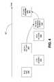
- FIG. 4is a block diagram that illustrates a mechanism employed by one embodiment of the STT system shown in FIG. 2 for an access point (AP) initiated TXOP where the AP signals the end of TXOP by setting an end of TXOP (EOT) indication on the final transmission to a client.
- APaccess point
- EOTend of TXOP
- FIG. 5is a block diagram that illustrates an alternative to the mechanism shown in FIG. 4 where the AP sends a CF-end with a client address, which is followed by a CF-end from the client with the same address of the client.
- FIG. 6is a block diagram that illustrates an alternative to the mechanism shown in FIG. 4 where the AP sends a CF-end with the client address in the location of a basic service set identifier (BSSID) field and the client responds with a CF-end with the BSSID and the AP responds with a final CF-end.
- BSSIDbasic service set identifier
- FIG. 7is a block diagram that illustrates a mechanism employed by one embodiment of the STT system shown in FIG. 2 for a station-initiated TXOP that is terminated by a first station sending a CF-end with the address of the second station in the location of the BSSID field and the second station responding with a CF-end with the second station address in the BSSID field.
- FIG. 8is a block diagram that illustrates a mechanism employed by one embodiment of the STT system shown in FIG. 2 with a BSSID of a station which either transmitted the latest beacon in an independent basic service set (IBSS) or an AP in a Direct Link communication.
- IBSSindependent basic service set
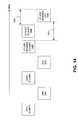
- FIG. 9is a block diagram that illustrates a mechanism employed by one embodiment of the STT system shown in FIG. 2 for a station-initiated TXOP that is terminated by a first station sending a CF-end to a second station, which responds with a CF-end to the third station, the latter which responds with a final CF-end.
- FIG. 10is a flow diagram that illustrates a method embodiment corresponding to the mechanism shown in FIG. 4 .
- FIG. 11is a flow diagram that illustrates a method embodiment corresponding to the mechanisms shown in FIGS. 5 and 7 .
- FIG. 12is a flow diagram that illustrates a method embodiment corresponding to the mechanisms shown in FIG. 6 .
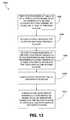
- FIG. 13is a flow diagram that illustrates a method embodiment corresponding to the mechanisms shown in FIGS. 8-9 .
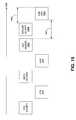
- FIG. 14is a block diagram that illustrates a NAV reset mechanism employed by an embodiment of the STT system shown in FIG. 2 .
- FIG. 15is a block diagram that illustrates an alternative to the NAV reset mechanism shown in FIG. 14 without using CF-end frames.
- FIG. 16provides a flow diagram that illustrates a method embodiment corresponding to the NAV reset mechanisms shown in FIGS. 14-15 .
- TXOPtransmit opportunity
- STTsymmetric transmit opportunity truncation
- the STT systems described hereincomprise functionality to truncate a TXOP in a symmetric manner in a plurality of devices. That is, in various STT systems and methods described herein, both access points (APs) and client stations (herein, clients) are also allowed to truncate their TXOPs by transmitting a CF-end frame.
- APsaccess points
- client stationsherein, clients
- a TXOP truncationis referred to as a TXOP truncation, where a NAV is first set for some maximum duration of time (e.g., the TXOP limit) and then reset when no more traffic (e.g., of frames) is left and there is some NAV time that still remains.
- a TXOPcomprises a signal exchange which may begin with the transmission of a short frame such as an RTS or CTS and ends with the last frame sent or received by the sender of the short frame (e.g., sender of the RTS or CTS).
- the truncation at both clients and APsresolve the various problems resulting from a reset that is not symmetrical, such as in conventional systems where the reset comes from a single device (though set by both devices through the RTS/CTS mechanisms).
- Various embodiments of the STT systemsprovide one or more mechanisms for the symmetrical truncation of TXOPs.
- the various embodiments of the STT systems described hereinmay similarly be applied to other systems and environments, such as ad hoc systems (e.g., independent BSS (IBSS) systems) or DLC systems, as well as other communication system environments.
- IBSSindependent BSS
- IEEE 802.11is prominently used herein as an example of a standard used in the disclosed exemplary wireless networks, the various systems and methods described herein may apply to virtually any wireless network.
- some embodiments of the STT systemsmay include some or all of the functionality of collision avoidance systems (CA systems) described in the co-pending application having Ser. No. 11/557,516 and incorporated herein by reference in its entirety.
- CA systemscollision avoidance systems
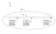
- FIG. 2shows an exemplary wireless LAN (WLAN) environment 100 in which various embodiments of a symmetric transmit opportunity (TXOP) truncation (STT) system 200 may be implemented.
- the STT system 200is configured as a basic service set (BSS), which comprises a plurality of stations or nodes, such as stations 202 , 204 , and 206 .
- BSSbasic service set
- Each of the stations 202 , 204 , and 206may be embodied as one of many wireless communication devices, including computers (desktop, portable, laptop, etc.), consumer electronic devices (e.g., multi-media players), compatible telecommunication devices, personal digital assistants (PDAs), or any other type of network devices such as printers, fax machines, scanners, hubs, switches, routers, set-top boxes, televisions with communication capability, etc.
- computersdesktop, portable, laptop, etc.
- consumer electronic devicese.g., multi-media players
- compatible telecommunication devicese.g., personal digital assistants (PDAs)
- PDAspersonal digital assistants
- any other type of network devicessuch as printers, fax machines, scanners, hubs, switches, routers, set-top boxes, televisions with communication capability, etc.
- the STT system 200 shown in FIG. 2comprises, in one embodiment, an access point (AP) station 202 (herein, also referred to, simply, as an AP) and one or more client stations 204 , 206 (herein, also referred to individually or collectively as client(s)).
- the STT system 200is configured in what may be referred to as an infrastructure mode, whereby clients 204 and 206 communicate frames directly with the AP 202 and not with each other.
- the various embodiments of STT systems 200are not limited to such arrangements, and in some embodiments, may be arranged in ad hoc or direct link communication configurations.
- Included within each of the AP 202 and clients 204 , 206is control logic 300 .
- the control logic 300implements MAC layer and PHY layer services.
- the MAC layer servicesprovide the capability for a given station to exchange MAC frames.
- the MAC layer servicesprovide management, control, or data frames for transmission between stations 202 , 204 , and 206 .
- the 802.11 MAC layer servicesmake use of at least three frame types (data, management, control), and within each type, various subtypes. For instance, request-to-send (RTS) frames, clear-to-send (CTS) frames, and CF-end frames are examples of control subtypes (e.g., control/CF-end refers to a control-type frame of the subtype, CF-end).
- RTSrequest-to-send
- CTSclear-to-send
- CF-end framesare examples of control subtypes (e.g., control/CF-end refers to a control-type frame of the subtype, CF-end).
- the frame bitsare passed to the PHY layer for transmission.
- control logic 300can be implemented in hardware, software, or a combination thereof. When implemented in whole or in part by software, control logic 300 is implemented in software stored in a memory that is executed by a suitable instruction execution system. When implemented in whole or in part by hardware, the control logic 300 can be implemented with any or a combination of the following technologies, which are all well known in the art: a discrete logic circuit(s) having logic gates for implementing logic functions upon data signals, an application specific integrated circuit (ASIC) having appropriate combinational logic gates, a programmable gate array(s) (PGA), a field programmable gate array (FPGA), etc.
- ASICapplication specific integrated circuit
- PGAprogrammable gate array
- FPGAfield programmable gate array
- control logic 300may include a PHY layer processor, MAC layer processor, or a combination of both (in the same or separate units), including, but not limited to, a digital signal processor (DSP), a microprocessor unit (MCU), a general purpose processor, and an application specific integrated circuit (ASIC), among others.
- DSPdigital signal processor
- MCUmicroprocessor unit
- ASICapplication specific integrated circuit
- the AP 202is typically connected to a wired network (e.g., Ethernet), not shown.
- the clientssuch as client 204
- the scanning processcan either be performed passively by listening for a beacon transmitted by one or more APs 202 , or actively by sending out probes to one or more APs 202 and choosing an AP that provides the best connection (e.g., in terms of signal strength and/or bit error ratio (BER)).
- BERbit error ratio
- associationinvolves the communication between the clients 204 , 206 and the AP 202 via a shared wireless medium 208 .
- the client 206may represent a hidden node to client 204 , and vice versa.
- FIGS. 3A-16Various mechanisms or methods for signal exchanges are illustrated in FIGS. 3A-16 to highlight various features of embodiments of the STT system 200 .
- the effectuating of the various functionality of the STT system 200is through the control logic 300 of each station (node).
- interframe spacese.g., extended interframe space (EIFS), short interframe space (SIFS), etc.
- EIFSextended interframe space
- SIFSshort interframe space
- FIGS. 3A-3Bshow one mechanism used by an embodiment of the STT system 200 to set a NAV and/or avoid EIFS for an AP-initiated TXOP.
- the AP 202sets a NAV prior to a TXOP 302 by starting the TXOP 302 with a short frame 304 (e.g., short to reduce the probability of error) at a low basic rate.
- blocks 302 and 304collectively comprise a TXOP.
- the short frame 304contains a duration value (e.g., the NAV setting) equal to the expected length of the TXOP 302 .
- the AP 202avoids any EIFS at the end of the TXOP 302 by sending a short frame 306 (typically containing a duration value of zero) at a low basic rate as the final frame of the TXOP 302 .
- blocks 302 and 306collectively comprise a TXOP. In each case, the rate is selected such that frames from the AP 202 reach all nodes in the network (e.g., BSS).
- FIGS. 4-9disclose various mechanisms employed (implemented) by certain embodiments of the STT system 200 that provide for symmetrical TXOP truncation using CF-end frames (herein, each of these frames also simply referred to as CF-end).
- CF-end frameseach of these frames also simply referred to as CF-end.
- FIGS. 4-9various mechanisms of communication between devices of one or more STT system embodiments are illustrated in FIGS. 4-9 and explained in the corresponding text.
- FIG. 4are blocks representing respective frames that are passed between the client 204 and the AP 202 to provide for symmetrical TXOP truncation.
- FIGS. 4-9disclose various mechanisms employed (implemented) by certain embodiments of the STT system 200 that provide for symmetrical TXOP truncation using CF-end frames (herein, each of these frames also simply referred to as CF-end).
- FIGS. 4-9various mechanisms of communication between devices of one or more STT system embodiments are illustrated in FIGS
- the AP-sourced framesare represented with blocks in the top row (indicated in parenthesis, with “AP”), and the client-sourced frames are represented with blocks in the second row (as indicated in the parenthesis as “client”).
- the sequence of frame transmissionadvances in time from left to right, as represented by the arrow time line 401 .
- an RTS frame sent by the AP 202begins the sequence, and a CF-end sent by the AP 202 ends the sequence.
- the first addresse.g., BC
- the second address(e.g., BSSID) is usually the transmitter address, but in one or more embodiments described herein, comprises the unicast destination address.
- the AP 202(not shown, but implied as denoted by the “AP” in parenthesis) sends an RTS frame (or RTS) 402
- the client 204(not shown, but implied as denoted by the “client” in parenthesis) responds by sending a CTS frame (or CTS) 404 .
- the sending of the RTS 402 and CTS 404results in the setting of a NAV around (e.g., close enough to decode frame transmissions all or at least most of the time) the respective devices.
- the AP 202sends one or more data frames 406 , each of which are acknowledged by the client 204 with an acknowledgement (ACK) frame 408 .
- ACKacknowledgement
- the final data frame 406 from the AP 202 to the client 204is “tagged” with an end of TXOP (EOT) indication.
- This EOT indicationcomprises a signal or flag to the client 204 to respond with a CF-end frame 410 after a SIFS interval.
- the CF-end frame 410may be preceded by a mandatory response frame, such as the ACK frame 408 (or a block acknowledgement (BA) frame, the latter not shown).
- a basic service set identifier (BSSID) field of the CF-end frame 410carries a BSSID (e.g., MAC address) of the AP 202 .
- BSSIDbasic service set identifier
- the AP 202recognizes its BSSID in the received CF-end frame 410 and responds to this CF-end frame 410 with a CF-end frame 412 .
- the TXOPis actively truncated by both devices 202 and 204 .
- FIG. 5illustrates an alternative to the mechanism shown in FIG. 4 . That is, the final frame in the TXOP sent by the AP 202 is a CF-end frame 502 comprising the address (e.g., MAC address) of the client 204 inside the BSSID field.
- the client 204recognizes its address in the CF-end frame 502 and responds after a SIFS interval with a CF-end frame 504 .
- the CF-end frame 504also comprises the client address inside the location of the BSSID field.
- This mechanism illustrated in FIG. 5is referred to as a “CF-end to self.”
- FIG. 6illustrates an alternative to the mechanism shown in FIG. 4 .
- the AP 202sends a CF-end frame 602 with the client MAC address inside the BSSID field.
- the clientresponds with a CF-end frame 604 having the BSSID of the AP 202 , to which the AP 202 responds with a CF-end frame 606 with the BSSID of the AP 202 .
- the AP 202acts as the final transmitter of the final CF-end frame, which may be desirable in relation to the EIFS inside a BSS since all associated clients receive the final CF-end frame (e.g., CF-end frame 606 ) from the AP 202 .
- the first CF-end frame 602uses a non-basic rate, and thereby functions similarly to the EOT frame indication (of final frame 406 ) shown in and described in association with FIG. 4 .
- a non-basic ratefor the first CF-end frame 602 , NAV truncation functionality is absent. That is, a CF-end frame is effective for NAV truncation when sent at a basic rate that all clients inside a defined BSS can receive and decode
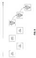
- FIGS. 7-9provide a generalized illustration of the above-described mechanisms, in addition to describing additional mechanisms, by showing an exchange of frames between two stations, station 1 (STA 1 ) (shown in a top row of FIGS. 7-9 ) and station 2 (STA 2 ) (shown in a second row of FIGS. 7-9 ).
- FIGS. 7-9there may be an exchange of frames with a third station such as an AP or other device (shown in a third row at the bottom of FIGS. 8-9 ).
- a third stationsuch as an AP or other device (shown in a third row at the bottom of FIGS. 8-9 ).
- the explanation of the various mechanisms shown in FIGS. 7-9is directed to the exchange of frames that commence after the exchange of CTS/RTS frames and data and ACK frames, the latter of which have already been described above in association with FIGS. 4-6 .
- FIG. 7illustrates a general principle of certain embodiments of the STT system 200 that any station that receives a CF-end frame 702 with its corresponding MAC address inside the location of the BSSID field responds to the CF-end frame 702 with a CF-end frame 704 .
- the address used inside the CF-end frame 702depends on the specific implementation. In general, if a CF-end frame 704 is required (a determination to be made by a client or an AP), the address of the transmitter of the next CF-end frame 704 is included inside the location of the BSSID field of CF-end frame 702 .
- the station's (e.g., STA 2 ) own addressis included in the BSSID field, or the broadcast address (BC), or any other address which is not immediately associated with another station address.
- BSSIDthe station's
- BCbroadcast address
- a client in infrastructure modewould typically include the BSSID of the AP, so that the AP generates a CF-end response.
- a client in IBSS modemay include the MAC address of the peer node to which it is communicating during the TXOP.
- An APmay or may not include an address other than a BSSID of the AP.
- STA 1comprises a client station 204
- STA 2comprises an AP station (or simply, AP) 202 .
- the mechanism shown in FIG. 7enables the AP 202 to respond to a CF-end 702 , which contains a matching BSSID (e.g., MAC address) with another CF-end 704 after SIFS (which in some implementations, may be a PIFS interval).
- BSSIDe.g., MAC address
- SIFSwhich in some implementations, may be a PIFS interval
- the CF-end 702 transmitted by the client station 204comprises the final frame in the TXOP of client station 204 , and in one embodiment, is an unacknowledged frame (hence, it is safe to transmit a CF-end 704 after SIFS).
- the BSSIDmakes the CF-end 702 specific to one AP, avoiding collisions between multiple APs transmitting a CF-end 704 .
- the CF-end 704clears the NAV around the AP 202 , which covers the entire BSS. Note that some implementations may not require the CF-end 704 . For instance, when the distance between the AP 202 and the client station 204 is small, a single CF-end from either the AP 202 or the client station 204 roughly resets the EIFS in the same coverage area, because the coverage areas for both devices largely overlap.
- the determination by the AP 202 to send a CF-end responsecan be based on the estimated distance of associated client stations 204 , 206 , and possibly in combination with the estimated distance of the transmitter of the CF-end. Such a determination can, for instance, be based on received signal strengths, or the PHY rates or modulation code schemes (MCSs) used to communicate with the client stations 204 , 206 . Other mechanisms may be used in the determination.
- MCSsmodulation code schemes
- the client 204may send a CF-end 702 with a duration value (which sets a NAV) corresponding to a defined time after the expected CF-end 704 to be sent by the AP 202 .
- the AP 202sends a CF-end 704 (CF-end response) with a duration of zero, which causes receivers of each CF-end to resume backoff at exactly, or substantially exactly, the same time (and hence, in one embodiment, superceding existing rules that allow an EIFS to follow a CF-end).
- the client 204may also send a CF-end 702 with a physical layer convergence protocol (PLCP) duration (which is signaled inside a SIG field or L-SIG field of the frame) equal to the CF-end itself plus SIFS plus the expected CF-end response duration from the AP 202 .
- the AP 202in one embodiment, is allowed to ignore this physical duration and respond with a CF-end 704 a SIFS interval after the end of the actual transmission of the CF-end 702 , as can be determined from the indicated rate and size of the CF-end 702 (e.g., 20 octets without an HT control field, 24 octets with an HT control field).
- the CF-end 704in one embodiment, comprises a regular PLCP duration.
- a third CF-end framemay be added to the frame sequence illustrated in FIG. 7 when the second station includes the BSSID.
- FIG. 8which includes the addition of an AP (implicitly represented by the bottom or third row frame 802 ).
- the TXOPis initiated by STA 1 sending a CF-end frame 802 to STA 2 , which responds with a CF-end frame 804 to the AP.
- the APresponds with a final CF-end frame 806 with the BSSID inside the BSSID field of CF-end frame 806 .
- the BSSIDmay be recognized by the station that transmitted the final IBSS beacon, as illustrated in FIG. 9 .
- STA 1sends a CF-end frame 902 addressed at STA 2 .
- STA 2responds with a CF-end frame 904 addressed at the BSSID of STA 2 .
- STA 3responds with a CF-end frame 906 .
- the BSSIDcan be the address of the station (e.g., STA 3 ) that transmitted the latest beacon in an IBSS, or it can be the address of the AP in case the communication between STA 1 and STA 2 comprises a Direct Link communication.
- the receiver address (RA) of a CF-end frameis equal to the broadcast address, which ensures that all stations within range receive the CF-end frame and process the same.
- the location of the BSSIDcan be used to indicate the destination of the CF-end.
- the recognition of the CF-end type/subtypeis enough for a receiver to truncate the NAV.
- the RA of the CF-end framecan be used to store the CF-end responder address, while the BSSID field can be used to store the BSSID.
- STT method 200 acomprises sending by an AP a final data frame of a transmit opportunity (TXOP) with an end of transmit opportunity (EOT) indicator included therein ( 1002 ), receiving by a client the final data frame ( 1004 ), the client responding by sending a CF-end frame, with an identifier (e.g., MAC address, etc.) of the AP included therein, to the AP to truncate the TXOP around the client ( 1006 ), the AP receiving the CF-end frame with the identifier ( 1008 ), and the AP sending a CF-end frame with the same identifier to the client to truncate the TXOP around the AP ( 1010 ).
- TXOPtransmit opportunity
- EOTend of transmit opportunity
- one method embodiment corresponding to method 200 acomprises sending (by an AP) a final data frame of a transmit opportunity (TXOP) with an end of transmit opportunity (EOT) indicator included therein, and responsive to receiving a CF-end frame with an identifier of the AP included therein to truncate the TXOP around the client, sending a CF-end frame with the same identifier to the client to truncate the TXOP around the AP.
- TXOPtransmit opportunity
- EOTend of transmit opportunity
- Another method embodiment corresponding to method 200 afrom the perspective of a client, comprises receiving (by a client) a final frame of a transmit opportunity (TXOP) from an AP, the final data frame having an end of transmit opportunity (EOT) indicator included therein, responding to the final frame by sending a CF-end frame, with an identifier of the AP included therein, to the AP to truncate the TXOP around the client and to prompt the AP to send a CF-end frame to truncate the TXOP around the AP.
- TXOPtransmit opportunity
- EOTend of transmit opportunity
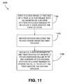
- STT method 200 bcomprises sending, by a first station (e.g., an AP), at the end of a TXOP a CF-end frame with an address of a second station (e.g., a client) included therein to truncate a TXOP around the first station ( 1102 ), receiving by the second station the CF-end frame from the first station ( 1104 ), the second station responding to the first station by sending a CF-end frame with the address of the second station included therein to truncate the TXOP around the second station ( 1106 ).
- a first statione.g., an AP
- a second statione.g., a client
- one method embodiment corresponding to method 200 b implemented at a first stationcomprises receiving a final frame of a TXOP from a second station (e.g., client) at the first station, and responsive to receiving the final frame of the TXOP, sending, at the end of the TXOP, a CF-end frame with an address of the second station included therein to truncate a TXOP around the first station and to prompt the second station to send a CF-end frame to truncate the TXOP around the second station.
- one method embodiment corresponding to method 200 b implemented at a second stationcomprises receiving (at the second station) a CF-end frame with an address of the second station included therein, the CF-end used to truncate a TXOP around a first station (e.g., AP), and responding to the first station by sending a CF-end frame with the address of the second station included therein to truncate the TXOP around the second station.
- a first statione.g., AP
- STT method 200 ccomprises an AP sending a CF-end frame at a non-basic rate (and hence acting as an EOT indicator) with the address of the client included therein ( 1202 ), the client receiving the CF-end frame ( 1204 ), the client responding by sending a CF-end frame having the address of the AP included therein, which truncates the TXOP around the client ( 1206 ), the AP receiving the CF-end frame sent by the client ( 1208 ), and the AP responding by sending a CF-end frame with the address of the AP included therein, resulting in the AP acting as the final transmitter of the final CF-end frame that truncates the TXOP around the AP ( 1210 ).
- One method embodiment corresponding to method 200 c implemented at an APcomprises an AP sending a CF-end frame at a non-basic rate (and hence acting as an EOT indicator) with the address of the client included therein, and responsive to receiving a client-TXOP truncating CF-end frame having the address of the AP included therein, responding by sending a CF-end frame with the address of the AP included therein, which truncates the TXOP around the AP.
- one method embodiment corresponding to method 200 c implemented at a clientcomprises receiving by a client a CF-end frame possibly at a non-basic rate (and hence acting as an EOT indicator) with the address of the client included therein, and responding by sending a CF-end frame having the address of the sending AP included therein, which truncates the TXOP around the client and prompts the AP to send a final CF-end frame that truncates the TXOP around the AP.
- STT method 200 dcomprises sending, by a first station, at the end of a TXOP a CF-end frame with an address of a second station included therein to truncate a TXOP around the first station ( 1302 ), receiving by the second station the CF-end frame from the first station ( 1304 ), the second station responding to the first station by sending a CF-end frame with an identifier included therein to a third station to truncate the TXOP around the second station ( 1306 ), the third station receiving the CF-end response frame ( 1308 ), the third station responding by sending a CF-end response frame with the identifier therein to the second station to truncate the TXOP around the third station ( 1310 ).
- each device participating in the methodology illustrated in FIG. 13performs portions of the described method 200 d that can be described similarly to the manner such perspective-based methods have been described previously in FIGS. 10-12 , and thus omitted here for brevity.
- FIG. 14illustrates various mechanisms for client-initiated TXOPs for embodiments of the STT system 200 , and in particular, mechanisms that focus on issues of NAV reset and backoff resumption involving CF-end frames or frames acting in particular circumstances with similar functionality to CF-end frames.
- the description that followsis based in part on the previous discussion corresponding to FIG. 7 for the case where STA 1 is a client and STA 2 is an AP.
- the clientmay transmit a short frame (EIFS set frame) 1404 with a defined frame check sequence (FCS) field 110 ( FIG.
- EIFS set frameshort frame
- FCSdefined frame check sequence
- the AP 202delays (e.g., by SIFS+EIFS set frame+EIFS ⁇ DIFS ⁇ CF-end frame, represented by duration interval 1401 ) the sending of the CF-end frame 1406 so that the transmission of frame 1406 finishes exactly (or substantially so) when the EIFS-DIFS finishes (the EIFS-DIFS represented by the duration interval denoted by 1403 ), so that either client (e.g., 204 , 206 ) starts DIFS (or more general, AIFS) at the same time.
- DIFSrefers to a first fixed part of the DCF backoff (DIFS)
- AIFSrefers to the EDCA backoff (AIFS).
- EIFS set frame 1404causes AIFS to start for clients 204 , 206 that cannot receive the CF-end 1406 from the AP 202 .
- the CF-end frame 1406 from the AP 102is transmitted during this time, such that all nodes start DIFS (or AIFS) at the same time.
- the EIFS set frame 1404can be a zero length frame (e.g., a preamble without a MAC payload).
- FIG. 15is a block diagram that illustrates the principles of the mechanism shown in FIG. 14 , without the use of CF-end frames.
- the CF-end frame 1402 of FIG. 14is replaced with an EOT frame 1502
- the CF-end frame 1406 of FIG. 14is replaced with an ACK frame 1504 .
- the mechanism illustrated in FIG. 15can be used to resume the backoff for all nodes within the range of either the client 204 or the AP 202 or both in the network at the same time (e.g., without part of the nodes having to wait for an EIFS to finish).
- the EOT frame 1502is sent to the AP 202 , followed after an SIFS interval by the EIFS set frame 1404 .
- the AP 202responds to the EOT frame 1502 (and ignores the EIFS set frame 1404 ) with the ACK frame 1504 .
- the ACK frame 1504ends at the same time as the interval 1403 after the end of the EIFS set frame 1404 .
- both the AP and the clientcan start an EIFS set frame at the same, or substantially same, time.
- one method embodiment of the STT system 200encompassing these mechanisms, the method referred to as 200 e and shown in FIG. 16 , comprises the client 204 sending a final data frame of a TXOP to the AP 202 ( 1602 ), the final frame having the form of a CF-end frame specific to a given AP or an EOT frame, sending an EIFS set frame, receiving by the AP 202 the CF-end frame after a defined interval (the defined interval being a SIFS, a PIFS, or duration 1401 described in association with FIG.
- a defined intervalbeing a SIFS, a PIFS, or duration 1401 described in association with FIG.
- the CF-end frameacts to clear the NAV ( 1612 ), as described above.
- each device participating in the methodology illustrated in FIG. 16performs portions of the described method 200 e that can be described similarly to the manner such perspective-based methods have been described previously in FIGS. 10-12 , and thus omitted here for brevity.
Landscapes
- Engineering & Computer Science (AREA)
- Signal Processing (AREA)
- Computer Networks & Wireless Communication (AREA)
- Multimedia (AREA)
- Mobile Radio Communication Systems (AREA)
Abstract
Description
Claims (31)
Priority Applications (8)
| Application Number | Priority Date | Filing Date | Title |
|---|---|---|---|
| US11/651,879US8031661B2 (en) | 2005-11-08 | 2007-01-10 | Symmetric transmit opportunity (TXOP) truncation |
| US13/251,772US8270385B2 (en) | 2005-11-08 | 2011-10-03 | Symmetric transmit opportunitty (TXOP) truncation |
| US13/591,654US8488550B2 (en) | 2005-11-08 | 2012-08-22 | Symmetric transmit opportunity (TXOP) truncation |
| US13/941,700US9125104B2 (en) | 2005-11-08 | 2013-07-15 | Symmetric transmit opportunity (TXOP) truncation |
| US14/838,520US10098160B2 (en) | 2005-11-08 | 2015-08-28 | Symmetric transmit opportunity (TXOP) truncation |
| US16/122,828US10856338B2 (en) | 2005-11-08 | 2018-09-05 | Symmetric transmit opportunity (TXOP) truncation |
| US16/908,044US12171031B2 (en) | 2005-11-08 | 2020-06-22 | Symmetric transmit opportunity (TXOP) truncation |
| US18/508,013US12101829B2 (en) | 2005-11-08 | 2023-11-13 | Symmetric transmit opportunity (TXOP) truncation |
Applications Claiming Priority (5)
| Application Number | Priority Date | Filing Date | Title |
|---|---|---|---|
| US73502405P | 2005-11-08 | 2005-11-08 | |
| US75782706P | 2006-01-10 | 2006-01-10 | |
| US75859506P | 2006-01-11 | 2006-01-11 | |
| US11/557,516US8374123B2 (en) | 2005-11-08 | 2006-11-08 | Collision avoidance systems and methods |
| US11/651,879US8031661B2 (en) | 2005-11-08 | 2007-01-10 | Symmetric transmit opportunity (TXOP) truncation |
Related Parent Applications (1)
| Application Number | Title | Priority Date | Filing Date |
|---|---|---|---|
| US11/557,516Continuation-In-PartUS8374123B2 (en) | 2005-11-08 | 2006-11-08 | Collision avoidance systems and methods |
Related Child Applications (1)
| Application Number | Title | Priority Date | Filing Date |
|---|---|---|---|
| US13/251,772DivisionUS8270385B2 (en) | 2005-11-08 | 2011-10-03 | Symmetric transmit opportunitty (TXOP) truncation |
Publications (2)
| Publication Number | Publication Date |
|---|---|
| US20070115882A1 US20070115882A1 (en) | 2007-05-24 |
| US8031661B2true US8031661B2 (en) | 2011-10-04 |
Family
ID=46327024
Family Applications (7)
| Application Number | Title | Priority Date | Filing Date |
|---|---|---|---|
| US11/651,879Active2028-05-23US8031661B2 (en) | 2005-11-08 | 2007-01-10 | Symmetric transmit opportunity (TXOP) truncation |
| US13/251,772ActiveUS8270385B2 (en) | 2005-11-08 | 2011-10-03 | Symmetric transmit opportunitty (TXOP) truncation |
| US13/591,654ActiveUS8488550B2 (en) | 2005-11-08 | 2012-08-22 | Symmetric transmit opportunity (TXOP) truncation |
| US13/941,700Active2027-06-22US9125104B2 (en) | 2005-11-08 | 2013-07-15 | Symmetric transmit opportunity (TXOP) truncation |
| US14/838,520Active2027-06-25US10098160B2 (en) | 2005-11-08 | 2015-08-28 | Symmetric transmit opportunity (TXOP) truncation |
| US16/122,828Active2026-12-24US10856338B2 (en) | 2005-11-08 | 2018-09-05 | Symmetric transmit opportunity (TXOP) truncation |
| US16/908,044ActiveUS12171031B2 (en) | 2005-11-08 | 2020-06-22 | Symmetric transmit opportunity (TXOP) truncation |
Family Applications After (6)
| Application Number | Title | Priority Date | Filing Date |
|---|---|---|---|
| US13/251,772ActiveUS8270385B2 (en) | 2005-11-08 | 2011-10-03 | Symmetric transmit opportunitty (TXOP) truncation |
| US13/591,654ActiveUS8488550B2 (en) | 2005-11-08 | 2012-08-22 | Symmetric transmit opportunity (TXOP) truncation |
| US13/941,700Active2027-06-22US9125104B2 (en) | 2005-11-08 | 2013-07-15 | Symmetric transmit opportunity (TXOP) truncation |
| US14/838,520Active2027-06-25US10098160B2 (en) | 2005-11-08 | 2015-08-28 | Symmetric transmit opportunity (TXOP) truncation |
| US16/122,828Active2026-12-24US10856338B2 (en) | 2005-11-08 | 2018-09-05 | Symmetric transmit opportunity (TXOP) truncation |
| US16/908,044ActiveUS12171031B2 (en) | 2005-11-08 | 2020-06-22 | Symmetric transmit opportunity (TXOP) truncation |
Country Status (1)
| Country | Link |
|---|---|
| US (7) | US8031661B2 (en) |
Cited By (2)
| Publication number | Priority date | Publication date | Assignee | Title |
|---|---|---|---|---|
| US20100165963A1 (en)* | 2008-12-31 | 2010-07-01 | Stmicroelectronics, Inc. | Robust unicast/broadcast/multicast communication protocol |
| US10716138B2 (en)* | 2016-04-13 | 2020-07-14 | Sony Corporation | Communication apparatus, communication method, and program |
Families Citing this family (56)
| Publication number | Priority date | Publication date | Assignee | Title |
|---|---|---|---|---|
| KR100765776B1 (en)* | 2005-12-13 | 2007-10-12 | 삼성전자주식회사 | Method and apparatus for avoiding collision in medium access of WLAN |
| TWI565278B (en)* | 2006-01-04 | 2017-01-01 | 內數位科技公司 | Method and apparatus for use at an access point and a station |
| US8014818B2 (en)* | 2006-01-04 | 2011-09-06 | Interdigital Technology Corporation | Methods and systems for providing efficient operation of multiple modes in a WLAN system |
| KR100728039B1 (en)* | 2006-01-05 | 2007-06-14 | 삼성전자주식회사 | Method and apparatus for transmitting control frame to hidden node in WLAN |
| EP1982435A4 (en)* | 2006-01-25 | 2012-07-25 | Xocyst Transfer Ag L L C | Transmit announcement indication |
| US8144676B2 (en)* | 2007-09-04 | 2012-03-27 | Conexant Systems, Inc. | Network allocation |
| US20110158163A1 (en)* | 2009-12-28 | 2011-06-30 | University Of Calcutta | Energy efficient integrated routing protocol |
| CA2747358C (en)* | 2010-07-27 | 2015-06-09 | Lg Electronics Inc. | Method and apparatus of accessing channel in wireless communication system |
| PL2966915T3 (en) | 2011-02-01 | 2017-11-30 | Huawei Technologies Co., Ltd. | Power save method, access point device, and station device |
| EP3349535B1 (en) | 2011-06-24 | 2020-02-19 | Interdigital Patent Holdings, Inc. | Method and apparatus for supporting wideband and multiple bandwidth transmission protocols |
| US9877284B2 (en)* | 2011-07-14 | 2018-01-23 | Lg Electronics Inc. | Method of communication based on power save mode in wireless local area network and apparatus for the same |
| CN102883460B (en)* | 2011-07-15 | 2017-12-05 | 中兴通讯股份有限公司 | A kind of service data transmission method and system |
| US9807796B2 (en)* | 2011-09-02 | 2017-10-31 | Qualcomm Incorporated | Systems and methods for resetting a network station |
| CN103002591B (en)* | 2011-09-15 | 2015-09-30 | 华为技术有限公司 | A kind of the method for NAV control, device, system and node are carried out to node |
| CN103037531B (en)* | 2011-10-09 | 2018-03-16 | 中兴通讯股份有限公司 | A kind of method and system of wireless site access channel |
| US9380492B2 (en)* | 2011-12-02 | 2016-06-28 | Intel Corporation | Methods, systems and apparatuses to enable short frames |
| WO2013082489A1 (en)* | 2011-12-02 | 2013-06-06 | Huawei Technologies Co., Ltd. | System and method for traffic signaling and control in a wireless network |
| WO2013147567A1 (en)* | 2012-03-30 | 2013-10-03 | 엘지전자 주식회사 | Method and device for controlling channel access in wireless lan system |
| US8619927B2 (en) | 2012-05-29 | 2013-12-31 | Magnolia Broadband Inc. | System and method for discrete gain control in hybrid MIMO/RF beamforming |
| US8649458B2 (en) | 2012-05-29 | 2014-02-11 | Magnolia Broadband Inc. | Using antenna pooling to enhance a MIMO receiver augmented by RF beamforming |
| US8644413B2 (en) | 2012-05-29 | 2014-02-04 | Magnolia Broadband Inc. | Implementing blind tuning in hybrid MIMO RF beamforming systems |
| US8767862B2 (en) | 2012-05-29 | 2014-07-01 | Magnolia Broadband Inc. | Beamformer phase optimization for a multi-layer MIMO system augmented by radio distribution network |
| US9154204B2 (en) | 2012-06-11 | 2015-10-06 | Magnolia Broadband Inc. | Implementing transmit RDN architectures in uplink MIMO systems |
| EP2910078B1 (en)* | 2012-10-18 | 2018-02-21 | LG Electronics Inc. | Method and apparatus for channel access in wireless lan system |
| US8797969B1 (en) | 2013-02-08 | 2014-08-05 | Magnolia Broadband Inc. | Implementing multi user multiple input multiple output (MU MIMO) base station using single-user (SU) MIMO co-located base stations |
| US9343808B2 (en) | 2013-02-08 | 2016-05-17 | Magnotod Llc | Multi-beam MIMO time division duplex base station using subset of radios |
| US9155110B2 (en) | 2013-03-27 | 2015-10-06 | Magnolia Broadband Inc. | System and method for co-located and co-channel Wi-Fi access points |
| US20140226740A1 (en) | 2013-02-13 | 2014-08-14 | Magnolia Broadband Inc. | Multi-beam co-channel wi-fi access point |
| US8989103B2 (en) | 2013-02-13 | 2015-03-24 | Magnolia Broadband Inc. | Method and system for selective attenuation of preamble reception in co-located WI FI access points |
| US9100968B2 (en) | 2013-05-09 | 2015-08-04 | Magnolia Broadband Inc. | Method and system for digital cancellation scheme with multi-beam |
| US9425882B2 (en) | 2013-06-28 | 2016-08-23 | Magnolia Broadband Inc. | Wi-Fi radio distribution network stations and method of operating Wi-Fi RDN stations |
| US8995416B2 (en) | 2013-07-10 | 2015-03-31 | Magnolia Broadband Inc. | System and method for simultaneous co-channel access of neighboring access points |
| US9497781B2 (en)* | 2013-08-13 | 2016-11-15 | Magnolia Broadband Inc. | System and method for co-located and co-channel Wi-Fi access points |
| GB2517755A (en)* | 2013-08-30 | 2015-03-04 | Ibm | State-changeable device |
| US9088898B2 (en) | 2013-09-12 | 2015-07-21 | Magnolia Broadband Inc. | System and method for cooperative scheduling for co-located access points |
| US9060362B2 (en) | 2013-09-12 | 2015-06-16 | Magnolia Broadband Inc. | Method and system for accessing an occupied Wi-Fi channel by a client using a nulling scheme |
| US9172454B2 (en) | 2013-11-01 | 2015-10-27 | Magnolia Broadband Inc. | Method and system for calibrating a transceiver array |
| US8891598B1 (en) | 2013-11-19 | 2014-11-18 | Magnolia Broadband Inc. | Transmitter and receiver calibration for obtaining the channel reciprocity for time division duplex MIMO systems |
| US8942134B1 (en) | 2013-11-20 | 2015-01-27 | Magnolia Broadband Inc. | System and method for selective registration in a multi-beam system |
| US8929322B1 (en) | 2013-11-20 | 2015-01-06 | Magnolia Broadband Inc. | System and method for side lobe suppression using controlled signal cancellation |
| US9294177B2 (en) | 2013-11-26 | 2016-03-22 | Magnolia Broadband Inc. | System and method for transmit and receive antenna patterns calibration for time division duplex (TDD) systems |
| US9014066B1 (en) | 2013-11-26 | 2015-04-21 | Magnolia Broadband Inc. | System and method for transmit and receive antenna patterns calibration for time division duplex (TDD) systems |
| US9042276B1 (en) | 2013-12-05 | 2015-05-26 | Magnolia Broadband Inc. | Multiple co-located multi-user-MIMO access points |
| US20150223268A1 (en)* | 2014-02-05 | 2015-08-06 | Nokia Corporation | Channel Access With Carrier Sensing Mechanisms |
| US9100154B1 (en) | 2014-03-19 | 2015-08-04 | Magnolia Broadband Inc. | Method and system for explicit AP-to-AP sounding in an 802.11 network |
| US9172446B2 (en) | 2014-03-19 | 2015-10-27 | Magnolia Broadband Inc. | Method and system for supporting sparse explicit sounding by implicit data |
| WO2015143668A1 (en)* | 2014-03-27 | 2015-10-01 | Intel Corporation | Methods and apparatus for distributing transmission opportunities in a wireless communication network |
| US9271176B2 (en) | 2014-03-28 | 2016-02-23 | Magnolia Broadband Inc. | System and method for backhaul based sounding feedback |
| JP6368035B2 (en)* | 2014-08-18 | 2018-08-01 | ウィルス インスティテュート オブ スタンダーズ アンド テクノロジー インコーポレイティド | Wireless communication method for simultaneous data communication and wireless communication terminal using the same |
| WO2016172620A1 (en)* | 2015-04-24 | 2016-10-27 | Newracom, Inc. | Preamble and payload for high efficiency (he) transmission |
| JP2018121094A (en) | 2015-06-05 | 2018-08-02 | シャープ株式会社 | Wireless communication apparatus, communication method, and communication system |
| JP2017123585A (en)* | 2016-01-08 | 2017-07-13 | ソニー株式会社 | Information processing device, communication system, information processing method, and program |
| JP2017152983A (en) | 2016-02-25 | 2017-08-31 | ソニー株式会社 | Information processing apparatus, communication system, information processing method and program |
| US10863539B2 (en) | 2016-09-22 | 2020-12-08 | Qualcomm Incorporated | Transmission opportunity truncation |
| US20230112373A1 (en)* | 2021-09-24 | 2023-04-13 | Peraso Technologies Inc. | Long range contention based access protocol network |
| WO2025104180A1 (en)* | 2023-11-14 | 2025-05-22 | Koninklijke Philips N.V. | Coordinated time division multiple access (ctdma) truncation procedure |
Citations (21)
| Publication number | Priority date | Publication date | Assignee | Title |
|---|---|---|---|---|
| US20020163933A1 (en)* | 2000-11-03 | 2002-11-07 | Mathilde Benveniste | Tiered contention multiple access (TCMA): a method for priority-based shared channel access |
| US20030112780A1 (en) | 2001-12-17 | 2003-06-19 | Koninklijke Philips Electronics N.V. | Time diversity combining to increase the reliability of the IEEE 802.11 WLAN receiver |
| US20030123405A1 (en) | 2001-12-27 | 2003-07-03 | Koninklijke Philips Electronics N.V. | Overlapping network allocation vector (ONAV) for avoiding collision in the IEEE 802.11 WLAN operating under HCF |
| US20030161340A1 (en)* | 2001-10-31 | 2003-08-28 | Sherman Matthew J. | Method and system for optimally serving stations on wireless LANs using a controlled contention/resource reservation protocol of the IEEE 802.11e standard |
| US20030174690A1 (en) | 2001-11-02 | 2003-09-18 | At&T Corp. | Wireless LANs and neighborhood capture |
| US20040143681A1 (en) | 2002-12-09 | 2004-07-22 | Mathilde Benveniste | Distributed architecture for deploying multiple wireless local-area network |
| US20040181597A1 (en) | 2003-03-13 | 2004-09-16 | Randy L. Ekl | Efficient peer-to-peer transmission in an infrastructure environment |
| US20050068900A1 (en) | 2003-09-30 | 2005-03-31 | Intel Corporation | Data burst transmission methods in WLAN devices and systems |
| US20050135295A1 (en)* | 2003-10-15 | 2005-06-23 | Walton Jay R. | High speed media access control and direct link protocol |
| US20050238016A1 (en)* | 2004-04-23 | 2005-10-27 | Yasuyuki Nishibayashi | Communication apparatus, communication system, and communication control program |
| US20060034219A1 (en)* | 2004-08-11 | 2006-02-16 | Daqing Gu | Signaling in a wireless network with sequential coordinated channel access |
| US7054296B1 (en)* | 1999-08-04 | 2006-05-30 | Parkervision, Inc. | Wireless local area network (WLAN) technology and applications including techniques of universal frequency translation |
| US20060245369A1 (en)* | 2005-04-19 | 2006-11-02 | Joern Schimmelpfeng | Quality of service in IT infrastructures |
| US20070008922A1 (en)* | 2005-07-08 | 2007-01-11 | Microsoft Corporation | Direct wireless client to client communication |
| US20070054632A1 (en)* | 2002-04-01 | 2007-03-08 | Texas Instruments Incorporated | Wireless Network Scheduling Data Frames Including Physical Layer Configuration |
| WO2007056747A2 (en) | 2005-11-08 | 2007-05-18 | Conexant Systems | Collision avoidance systems and methods |
| US20070160021A1 (en)* | 2006-01-06 | 2007-07-12 | Xhafa Ariton E | Methods and apparatus to provide fairness for wireless local area networks that use long network allocation vector (NAV) mechanisms |
| US20070171858A1 (en)* | 2006-01-04 | 2007-07-26 | Interdigital Technology Corporation | Methods and systems for providing efficient operation of multiple modes in a wlan system |
| US7251232B1 (en)* | 2000-11-22 | 2007-07-31 | Cisco Technology, Inc. | Point-controlled contention arbitration in multiple access wireless LANs |
| US20070217352A1 (en)* | 2006-01-05 | 2007-09-20 | Samsung Electronics Co., Ltd. | Method and apparatus for transmitting control frame to hidden node in wireless LAN |
| US20090310619A1 (en)* | 2002-11-19 | 2009-12-17 | Bae Systems Information And Electronic Systems Integration Inc. | Bandwidth efficient wireless network modem |
Family Cites Families (18)
| Publication number | Priority date | Publication date | Assignee | Title |
|---|---|---|---|---|
| JP2001339391A (en) | 2000-05-25 | 2001-12-07 | Matsushita Electric Works Ltd | Wireless communication unit |
| US7161951B1 (en)* | 2001-06-12 | 2007-01-09 | At&T Corp. | Mechanism for implementing virtual carrier sense |
| JP2003008587A (en) | 2001-06-19 | 2003-01-10 | Sony Corp | Radio access method, radio access system, radio access point and radio mobile terminal |
| US7852823B2 (en) | 2001-09-17 | 2010-12-14 | Sharp Kabushiki Kaisha | Communication management method, communication terminal, communication management program, recording medium containing the communication management program, and communication system |
| US20050068924A1 (en)* | 2001-11-12 | 2005-03-31 | Jan Lindskog | System and method for providing quality of service in ieee 802.11 systems |
| US7698550B2 (en)* | 2002-11-27 | 2010-04-13 | Microsoft Corporation | Native wi-fi architecture for 802.11 networks |
| RU2358397C2 (en)* | 2003-05-09 | 2009-06-10 | Конинклейке Филипс Электроникс Н.В. | Measurement of activity diagram of communication medium in wireless networks and obtaining information from activity diagram |
| US7512070B2 (en) | 2003-06-23 | 2009-03-31 | Intel Corporation | Adaptive use of a transmit opportunity |
| JP4047836B2 (en)* | 2004-04-02 | 2008-02-13 | 株式会社東芝 | COMMUNICATION DEVICE, COMMUNICATION SYSTEM, COMMUNICATION METHOD, AND COMMUNICATION CONTROL PROGRAM |
| US7889645B2 (en)* | 2004-06-17 | 2011-02-15 | Qualcomm Incorporated | Hybrid coordination function implementation |
| KR100608006B1 (en)* | 2004-08-31 | 2006-08-02 | 삼성전자주식회사 | Data transmission methods in wireless LAN, access point device and station device |
| JP4599135B2 (en)* | 2004-11-02 | 2010-12-15 | キヤノン株式会社 | Information processing apparatus and information processing method |
| JP2008521322A (en)* | 2004-11-22 | 2008-06-19 | コーニンクレッカ フィリップス エレクトロニクス エヌ ヴィ | Method and apparatus for separating radio stations in a wireless network |
| JP2006174327A (en)* | 2004-12-20 | 2006-06-29 | Toshiba Corp | COMMUNICATION DEVICE, RADIO COMMUNICATION TERMINAL, RADIO COMMUNICATION SYSTEM, RADIO COMMUNICATION METHOD |
| GB2427978A (en)* | 2005-06-30 | 2007-01-10 | Nokia Corp | Setting up a direct link between peripheral and device in a WLAN |
| US7944897B2 (en) | 2005-11-03 | 2011-05-17 | Samsung Electronics Co., Ltd. | Method and system for addressing channel access unfairness in IEEE 802.11n wireless networks |
| TWI565278B (en) | 2006-01-04 | 2017-01-01 | 內數位科技公司 | Method and apparatus for use at an access point and a station |
| WO2013147567A1 (en)* | 2012-03-30 | 2013-10-03 | 엘지전자 주식회사 | Method and device for controlling channel access in wireless lan system |
- 2007
- 2007-01-10USUS11/651,879patent/US8031661B2/enactiveActive
- 2011
- 2011-10-03USUS13/251,772patent/US8270385B2/enactiveActive
- 2012
- 2012-08-22USUS13/591,654patent/US8488550B2/enactiveActive
- 2013
- 2013-07-15USUS13/941,700patent/US9125104B2/enactiveActive
- 2015
- 2015-08-28USUS14/838,520patent/US10098160B2/enactiveActive
- 2018
- 2018-09-05USUS16/122,828patent/US10856338B2/enactiveActive
- 2020
- 2020-06-22USUS16/908,044patent/US12171031B2/enactiveActive
Patent Citations (21)
| Publication number | Priority date | Publication date | Assignee | Title |
|---|---|---|---|---|
| US7054296B1 (en)* | 1999-08-04 | 2006-05-30 | Parkervision, Inc. | Wireless local area network (WLAN) technology and applications including techniques of universal frequency translation |
| US20020163933A1 (en)* | 2000-11-03 | 2002-11-07 | Mathilde Benveniste | Tiered contention multiple access (TCMA): a method for priority-based shared channel access |
| US7251232B1 (en)* | 2000-11-22 | 2007-07-31 | Cisco Technology, Inc. | Point-controlled contention arbitration in multiple access wireless LANs |
| US20030161340A1 (en)* | 2001-10-31 | 2003-08-28 | Sherman Matthew J. | Method and system for optimally serving stations on wireless LANs using a controlled contention/resource reservation protocol of the IEEE 802.11e standard |
| US20030174690A1 (en) | 2001-11-02 | 2003-09-18 | At&T Corp. | Wireless LANs and neighborhood capture |
| US20030112780A1 (en) | 2001-12-17 | 2003-06-19 | Koninklijke Philips Electronics N.V. | Time diversity combining to increase the reliability of the IEEE 802.11 WLAN receiver |
| US20030123405A1 (en) | 2001-12-27 | 2003-07-03 | Koninklijke Philips Electronics N.V. | Overlapping network allocation vector (ONAV) for avoiding collision in the IEEE 802.11 WLAN operating under HCF |
| US20070054632A1 (en)* | 2002-04-01 | 2007-03-08 | Texas Instruments Incorporated | Wireless Network Scheduling Data Frames Including Physical Layer Configuration |
| US20090310619A1 (en)* | 2002-11-19 | 2009-12-17 | Bae Systems Information And Electronic Systems Integration Inc. | Bandwidth efficient wireless network modem |
| US20040143681A1 (en) | 2002-12-09 | 2004-07-22 | Mathilde Benveniste | Distributed architecture for deploying multiple wireless local-area network |
| US20040181597A1 (en) | 2003-03-13 | 2004-09-16 | Randy L. Ekl | Efficient peer-to-peer transmission in an infrastructure environment |
| US20050068900A1 (en) | 2003-09-30 | 2005-03-31 | Intel Corporation | Data burst transmission methods in WLAN devices and systems |
| US20050135295A1 (en)* | 2003-10-15 | 2005-06-23 | Walton Jay R. | High speed media access control and direct link protocol |
| US20050238016A1 (en)* | 2004-04-23 | 2005-10-27 | Yasuyuki Nishibayashi | Communication apparatus, communication system, and communication control program |
| US20060034219A1 (en)* | 2004-08-11 | 2006-02-16 | Daqing Gu | Signaling in a wireless network with sequential coordinated channel access |
| US20060245369A1 (en)* | 2005-04-19 | 2006-11-02 | Joern Schimmelpfeng | Quality of service in IT infrastructures |
| US20070008922A1 (en)* | 2005-07-08 | 2007-01-11 | Microsoft Corporation | Direct wireless client to client communication |
| WO2007056747A2 (en) | 2005-11-08 | 2007-05-18 | Conexant Systems | Collision avoidance systems and methods |
| US20070171858A1 (en)* | 2006-01-04 | 2007-07-26 | Interdigital Technology Corporation | Methods and systems for providing efficient operation of multiple modes in a wlan system |
| US20070217352A1 (en)* | 2006-01-05 | 2007-09-20 | Samsung Electronics Co., Ltd. | Method and apparatus for transmitting control frame to hidden node in wireless LAN |
| US20070160021A1 (en)* | 2006-01-06 | 2007-07-12 | Xhafa Ariton E | Methods and apparatus to provide fairness for wireless local area networks that use long network allocation vector (NAV) mechanisms |
Non-Patent Citations (10)
| Title |
|---|
| ANSI/IEEE Std 802.11, 1999 Edition (R2003). |
| Final Office Action on U.S. Appl. No. 11/557,516, mailed Jan. 12, 2011. |
| International Preliminary Examination Report for PCT/US06/60663, completed Jun. 18, 2009. |
| International Search Report and Written Opinion. |
| International Search Report for PCT/US07/60320 dated Oct. 26, 2007. |
| Michael Fischer, QoS Baseline Proposal, IEEE 802.11 Standards Committee, Document IEEE 802.11-00/360R1 (Nov. 7, 2000).* |
| Office Action on U.S. Appl. No. 11/557,516, mailed Apr. 28, 2009. |
| Office Action on U.S. Appl. No. 11/557,516, mailed May 13, 2010. |
| Office Action on U.S. Appl. No. 11/557,516, mailed Nov. 6, 2009. |
| Search report for co-pending PCT Application No. PCT/US06/060663 dated Dec. 3, 2007, as well as Written Opinion dated Oct. 29, 2007. |
Cited By (4)
| Publication number | Priority date | Publication date | Assignee | Title |
|---|---|---|---|---|
| US20100165963A1 (en)* | 2008-12-31 | 2010-07-01 | Stmicroelectronics, Inc. | Robust unicast/broadcast/multicast communication protocol |
| US8625570B2 (en)* | 2008-12-31 | 2014-01-07 | Stmicroelectronics, Inc. | Robust unicast/broadcast/multicast communication protocol |
| US9538525B2 (en) | 2008-12-31 | 2017-01-03 | Stmicroelectronics, Inc. | Robust unicast/broadcast/multicast communication protocol |
| US10716138B2 (en)* | 2016-04-13 | 2020-07-14 | Sony Corporation | Communication apparatus, communication method, and program |
Also Published As
| Publication number | Publication date |
|---|---|
| US20190174555A1 (en) | 2019-06-06 |
| US8488550B2 (en) | 2013-07-16 |
| US20140029433A1 (en) | 2014-01-30 |
| US20070115882A1 (en) | 2007-05-24 |
| US20150373745A1 (en) | 2015-12-24 |
| US10098160B2 (en) | 2018-10-09 |
| US9125104B2 (en) | 2015-09-01 |
| US20120027000A1 (en) | 2012-02-02 |
| US10856338B2 (en) | 2020-12-01 |
| US12171031B2 (en) | 2024-12-17 |
| US8270385B2 (en) | 2012-09-18 |
| US20120307790A1 (en) | 2012-12-06 |
| US20200322996A1 (en) | 2020-10-08 |
Similar Documents
| Publication | Publication Date | Title |
|---|---|---|
| US12171031B2 (en) | Symmetric transmit opportunity (TXOP) truncation | |
| US10201015B2 (en) | Collision avoidance systems and methods | |
| US20070133447A1 (en) | Dual CTS protection systems and methods | |
| US9820302B2 (en) | Channel access method in wireless communication system and apparatus for same | |
| EP1972087B1 (en) | Symmetric transmit opportunity (txop) truncation | |
| KR101767120B1 (en) | Channel access method and apparatus therefor | |
| US20150230244A1 (en) | Method and device for transmitting and receiving traffic indication map in wireless lan system | |
| KR20150010746A (en) | Method for transmitting and receiving signal of station operable in power saving mode in wireless communication system, and device therefor | |
| US20130128839A1 (en) | Method and system for contention-based medium access schemes for directional wireless transmission with asymmetric antenna system (aas) in wireless communication systems | |
| WO2014042434A1 (en) | Method and apparatus for scanning in wireless lan | |
| CN101401334B (en) | Symmetric transmit opportunity(txop) truncation | |
| US12101829B2 (en) | Symmetric transmit opportunity (TXOP) truncation |
Legal Events
| Date | Code | Title | Description |
|---|---|---|---|
| AS | Assignment | Owner name:CONEXANT SYSTEMS, INC., CALIFORNIA Free format text:ASSIGNMENT OF ASSIGNORS INTEREST;ASSIGNOR:WENTINK, MENZO;REEL/FRAME:018782/0584 Effective date:20070110 | |
| AS | Assignment | Owner name:THE BANK OF NEW YORK TRUST COMPANY, N.A., ILLINOIS Free format text:SECURITY AGREEMENT;ASSIGNOR:CONEXANT SYSTEMS, INC.;REEL/FRAME:019210/0962 Effective date:20061113 | |
| AS | Assignment | Owner name:CONEXANT SYSTEMS INC., CALIFORNIA Free format text:RELEASE BY SECURED PARTY;ASSIGNOR:BANK OF NEW YORK MELLON TRUST COMPANY, N.A. (FORMERLY, BANK OF NEW YORK TRUST COMPANY, N.A.);REEL/FRAME:021731/0807 Effective date:20081017 Owner name:CONEXANT SYSTEMS INC.,CALIFORNIA Free format text:RELEASE BY SECURED PARTY;ASSIGNOR:BANK OF NEW YORK MELLON TRUST COMPANY, N.A. (FORMERLY, BANK OF NEW YORK TRUST COMPANY, N.A.);REEL/FRAME:021731/0807 Effective date:20081017 | |
| AS | Assignment | Owner name:XOCYST TRANSFER AG L.L.C., DELAWARE Free format text:ASSIGNMENT OF ASSIGNORS INTEREST;ASSIGNOR:CONEXANT SYSTEMS, INC.;REEL/FRAME:022043/0607 Effective date:20081016 Owner name:XOCYST TRANSFER AG L.L.C.,DELAWARE Free format text:ASSIGNMENT OF ASSIGNORS INTEREST;ASSIGNOR:CONEXANT SYSTEMS, INC.;REEL/FRAME:022043/0607 Effective date:20081016 | |
| AS | Assignment | Owner name:INTELLECTUAL VENTURES I LLC, DELAWARE Free format text:MERGER;ASSIGNOR:XOCYST TRANSFER AG L.L.C.;REEL/FRAME:026637/0603 Effective date:20110718 | |
| STCF | Information on status: patent grant | Free format text:PATENTED CASE | |
| FPAY | Fee payment | Year of fee payment:4 | |
| MAFP | Maintenance fee payment | Free format text:PAYMENT OF MAINTENANCE FEE, 8TH YEAR, LARGE ENTITY (ORIGINAL EVENT CODE: M1552); ENTITY STATUS OF PATENT OWNER: LARGE ENTITY Year of fee payment:8 | |
| MAFP | Maintenance fee payment | Free format text:PAYMENT OF MAINTENANCE FEE, 12TH YEAR, LARGE ENTITY (ORIGINAL EVENT CODE: M1553); ENTITY STATUS OF PATENT OWNER: LARGE ENTITY Year of fee payment:12 |