US8031178B2 - Keyboard with chassis structure - Google Patents
Keyboard with chassis structureDownload PDFInfo
- Publication number
- US8031178B2 US8031178B2US10/896,554US89655404AUS8031178B2US 8031178 B2US8031178 B2US 8031178B2US 89655404 AUS89655404 AUS 89655404AUS 8031178 B2US8031178 B2US 8031178B2
- Authority
- US
- United States
- Prior art keywords
- key
- actuated
- dome
- switch
- keyboard apparatus
- Prior art date
- Legal status (The legal status is an assumption and is not a legal conclusion. Google has not performed a legal analysis and makes no representation as to the accuracy of the status listed.)
- Active, expires
Links
Images


Classifications
- G—PHYSICS
- G06—COMPUTING OR CALCULATING; COUNTING
- G06F—ELECTRIC DIGITAL DATA PROCESSING
- G06F3/00—Input arrangements for transferring data to be processed into a form capable of being handled by the computer; Output arrangements for transferring data from processing unit to output unit, e.g. interface arrangements
- G06F3/01—Input arrangements or combined input and output arrangements for interaction between user and computer
- G06F3/02—Input arrangements using manually operated switches, e.g. using keyboards or dials
- G06F3/023—Arrangements for converting discrete items of information into a coded form, e.g. arrangements for interpreting keyboard generated codes as alphanumeric codes, operand codes or instruction codes
- G06F3/0233—Character input methods
- G06F3/0234—Character input methods using switches operable in different directions
- G—PHYSICS
- G06—COMPUTING OR CALCULATING; COUNTING
- G06F—ELECTRIC DIGITAL DATA PROCESSING
- G06F1/00—Details not covered by groups G06F3/00 - G06F13/00 and G06F21/00
- G06F1/16—Constructional details or arrangements
- G06F1/1613—Constructional details or arrangements for portable computers
- G06F1/1626—Constructional details or arrangements for portable computers with a single-body enclosure integrating a flat display, e.g. Personal Digital Assistants [PDAs]
- G—PHYSICS
- G06—COMPUTING OR CALCULATING; COUNTING
- G06F—ELECTRIC DIGITAL DATA PROCESSING
- G06F1/00—Details not covered by groups G06F3/00 - G06F13/00 and G06F21/00
- G06F1/16—Constructional details or arrangements
- G06F1/1613—Constructional details or arrangements for portable computers
- G06F1/1633—Constructional details or arrangements of portable computers not specific to the type of enclosures covered by groups G06F1/1615 - G06F1/1626
- G06F1/1662—Details related to the integrated keyboard
- G06F1/1664—Arrangements for ergonomically adjusting the disposition of keys of the integrated keyboard
- H—ELECTRICITY
- H01—ELECTRIC ELEMENTS
- H01H—ELECTRIC SWITCHES; RELAYS; SELECTORS; EMERGENCY PROTECTIVE DEVICES
- H01H2225/00—Switch site location
- H01H2225/01—Different switch sites under one actuator in same plane
Definitions
- This technologyrelates generally to the field of input systems for electronic devices, and particularly to a keyboard that is especially well-suited for use in a hand-held mobile communication device.
- Hand-held mobile communication devicesmay include a combined text-entry and telephony keyboard. Examples of such mobile devices include cellular telephones, wireless personal digital assistants (PDAs), two-way paging devices, and others.
- the keyboardcan be actuated with the fingers of one or both of the user's hands.
- a keyboard apparatuscomprises a group of switches, a key having a corresponding group of plungers, and a chassis structure including a panel and a post.
- the postprojects upward from the panel to support the key for manual movement pivotally into multiple actuated positions in which the plungers actuate the switches.
- the panelhas a group of apertures through which the plungers are movable into actuating engagement with the switches upon such multi-directional movement of the key.
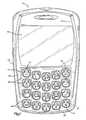
- FIG. 1is a front view of a mobile device with a keyboard.
- FIG. 2is a block diagram schematically showing parts of the device of FIG. 1 .
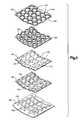
- FIG. 3is an exploded view of parts of the device of FIG. 1 .
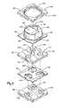
- FIG. 4is an exploded view showing enlarged portions of the parts shown in FIG. 3 .
- FIG. 5is an inverted view of a part shown in an upright position in FIG. 4 .
- FIG. 6is an enlarged front view of parts shown in FIG. 1 .
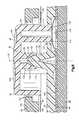
- FIG. 7is a sectional view taken on line 7 - 7 of FIG. 6 .
- FIG. 8is a sectional view taken on line 8 - 8 of FIG. 6 .
- the apparatus 10 shown in FIG. 1has parts that are examples of the elements recited in the claims.
- This apparatus 10is a hand-held mobile communication device including a housing 12 , a keyboard 14 and an output device 16 .
- this example of an output deviceis a display 16 , which is preferably a full graphic LCD.
- a processing device 18which is shown schematically in FIG. 2 , is contained within the housing 12 . The processing device 18 controls the operation of the display 16 , as well as the overall operation of the mobile device 10 , in response to actuation of the keyboard 14 by the user.
- a keyboard 14is defined in part by a front panel 20 of the housing 12 , and in part by a plurality of acutatable keys 22 at the panel 20 .
- the keys 22 and their corresponding actuation indicia 24together define a telephone keypad 25 and an overlapping text-entry keyboard 27 .
- the keyboard 14 as a wholeis thus configured for operation of the mobile device 10 in a telephony mode, in a text-entry mode, or in both the telephony mode and the text-entry mode.
- the mobile device 10is operative as indicated schematically in FIG. 2 .
- other parts of the mobile device 10also are shown schematically in FIG. 2 .
- Theseinclude a communications subsystem 30 ; a short-range communications subsystem 32 ; the keyboard 14 and the display 16 , along with other input/output devices 36 , 38 , 40 and 42 ; as well as memory devices 44 , 46 and various other device subsystems 48 .
- the mobile device 10is preferably a two-way communication device having voice and data communication capabilities and preferably has the capability to communicate with other computer systems via the Internet.
- Operating system software executed by the processing device 18is preferably stored in a persistent store, such as a flash memory 44 , but may be stored in other types of memory devices, such as a read only memory (ROM) or similar storage element.
- system software, specific device applications, or parts thereofmay be temporarily loaded into a volatile store, such as a random access memory (RAM) 46 .
- Communication signals received by the mobile device 10also may be stored to the RAM 46 .
- the processing device 18in addition to its operating system functions, enables execution of software applications 50 A- 50 N on the device 10 .
- a predetermined set of applications that control basic device operations, such as data and voice communications 50 A and 50 B,may be installed on the device 10 during manufacture.
- a personal information manager (PIM) applicationmay be installed during manufacture.
- the PIMis preferably capable of organizing and managing data items, such as e-mail, calendar events, voice mails, appointments, and task items.
- the PIM applicationis also preferably capable of sending and receiving data items via a wireless network 52 .
- the PIM data itemsare seamlessly integrated, synchronized and updated via the wireless network 52 with the device user's corresponding data items stored or associated with a host computer system.
- the communication subsystem 30includes a receiver 54 , a transmitter 56 , and one or more antennas 58 and 60 .
- the communication subsystem 30also includes a processing module, such as a digital signal processor (DSP) 62 , and local oscillators (LOs) 64 .
- DSPdigital signal processor
- LOslocal oscillators
- the mobile device 10may include a communication subsystem 30 designed to operate with the MobitexTM, Data TACTM or General Packet Radio Service (GPRS) mobile data communication networks and also designed to operate with any of a variety of voice communication networks, such as AMPS, TDMA, CDMA, PCS, GSM, etc. Other types of data and voice networks, both separate and integrated, may also be utilized with the mobile device 10 .
- GPRSGeneral Packet Radio Service
- Network access requirementsvary depending upon the type of communication system. For example, in the Mobitex and DataTAC networks, mobile devices are registered on the network using a unique personal identification number or PIN associated with each device. In GPRS networks, however, network access is associated with a subscriber or user of a device. A GPRS device therefore requires a subscriber identity module, commonly referred to as a SIM card, in order to operate on a GPRS network.
- SIM cardsubscriber identity module
- the mobile device 10may send and receive communication signals over the communication network 52 .
- Signals received from the communication network 52 by the antenna 58are routed to the receiver 54 , which provides for signal amplification, frequency down conversion, filtering, channel selection, etc., and may also provide analog to digital conversion. Analog-to-digital conversion of the received signal allows the DSP 62 to perform more complex communication functions, such as demodulation and decoding.
- signals to be transmitted to the network 52are processed (e.g. modulated and encoded) by the DSP 62 and are then provided to the transmitter 56 for digital to analog conversion, frequency up conversion, filtering, amplification and transmission to the communication network 52 (or networks) via the antenna 58 .
- the DSP 62provides for control of the receiver 54 and the transmitter 56 .
- gains applied to communication signals in the receiver 54 and transmitter 56may be adaptively controlled through automatic gain control algorithms implemented in the DSP 62 .
- a received signalsuch as a text message or web page download
- the received signalis then further processed by the processing device 18 for an output to the display 16 , or alternatively to some other auxiliary I/O device 36 .
- a device usermay also compose data items, such as e-mail messages, using the keyboard 14 and/or some other auxiliary I/O device 36 , such as a touchpad, a rocker switch, a thumb-wheel, or some other type of input device.
- the composed data itemsmay then be transmitted over the communication network 52 via the communication subsystem 30 .
- a voice communication modeIn a voice communication mode, overall operation of the device is substantially similar to the data communication mode, except that received signals are output to a speaker 40 , and signals for transmission are generated by a microphone 42 .
- Alternative voice or audio I/O subsystemssuch as a voice message recording subsystem, may also be implemented on the device 10 .
- the display 16may also be utilized in voice communication mode, for example to display the identity of a calling party, the duration of a voice call, or other voice call related information.
- the short-range communications subsystem 32enables communication between the mobile device 10 and other proximate systems or devices, which need not necessarily be similar devices.
- the short-range communications subsystem 32may include an infrared device and associated circuits and components, or a BluetoothTM communication module to provide for communication with similarly-enabled systems and devices.
- the mobile device 10may also include a predictive text computer program that is used in conjunction with the keyboard 14 .
- a predictive text computer programmay, for example, be used to predict a complete word or phrase from one or more keystrokes. If the predictive text computer program does not successfully predict a desired word or phrase, then text-entry characters may be entered more completely, albeit more slowly, by selecting the appropriate characters on the keys 22 .
- the keyboard 14includes a telephone keypad 25 and an overlapping text-entry keyboard 27 .
- the actuation indicia 24is preferably located on the keys, as shown in the example of FIG. 1 .
- the keys 22 and their corresponding actuation indicia 24together define an entire telephone keypad 25 with functional keys and numeral keys 1-9 and 0, and further define an entire QWERTY keyboard 27 with functional keys and letter keys A-Z.
- Each key 22is configured for multi-directional movement pivotally into and out of multiple actuated positions that correspond to characters in the telephone keypad 25 and/or the overlapping QWERTY keyboard 27 . This presents the user of the device 10 with a compact arrangement of multi-purpose telephone and text-entry keys 22 .
- each key 22 in the example shown in FIG. 1has three different actuated positions.
- the key 70 at the upper left-hand corner of the telephone keypad 25thus has an actuated position to “pick up,” and further has two additional actuated positions for text entry of the letters Q and W, respectively, in the overlapping QWERTY keyboard 27 .
- the key 72 at the upper right-hand corner of the telephone keypad 25similarly has an actuated position to “hang up,” along with two additional actuated positions for text entry of the letters O and P, respectively, in the overlapping QWERTY keyboard 27 .
- Other keys in the telephone keypad 25include a group of keys for telephone numerals 1-9. Each of those keys 22 has an actuated position for the respective telephone numeral, and further has two more actuated positions for respective letters in the QWERTY keyboard 27 . Within that group of telephone keys 22 is a smaller group for telephone numerals 2-9. The actuated position for the telephone numeral at each of those keys 22 further serves as a common actuated position for all of the telephone keypad letters that correspond to the respective numeral. For example, the actuated position for the telephone numeral 9 is the same as the actuated position for each of the telephone keypad letters W, X, Y and Z.
- the remaining text-entry letters and functional characters that complete the entire QWERTY keyboard 27are provided on six additional keys 22 that do not overlap the telephone keypad 25 .
- the six non-overlapping keys 22appear in columns directly beneath the “pick up” and “hang up” keys 70 and 72 .
- the actuated positions of the six non-overlapping keys 22all correspond to text entry letters and functions.
- the internal structure of the keyboard 14is illustrated in FIG. 3 .
- Thisincludes a molded plastic sheet 80 that defines the keys 22 , an underlying chassis 82 that supports the keys 22 , and a dome actuator panel 84 beneath the chassis 82 .
- the dome actuator panel 84overlies a printed circuit board (PCB) 86 .
- PCBprinted circuit board
- the keys 22are formed as raised portions of the molded plastic sheet 80 that project upward from a thin planar base portion 90 . Every key 22 has the same size and shape. Each key 22 on the sheet 80 thus has the configuration of the individual key 22 that is shown in enlarged detail in FIGS. 4-8 .
- a side wall 92 of the key 22projects vertically from the base portion 90 of the plastic sheet 80 .
- the side wall 92provides the key 22 with a generally rectangular peripheral shape with rounded corners, as best shown in FIG. 6 .
- a top wall 94 of the key 22has an actuation surface 96 upon which the actuation indicia 24 ( FIG. 1 ) appears.
- the contour of the actuation surface 96defines distinct surface portions that correspond to the actuated positions of the key 22 .
- the actuation surface 96is recessed from an otherwise dome-shaped contour at a plurality of distinct concave scalloped portions. These include a single major portion 100 and two minor portions 102 and 104 .
- the major portion 100has an oval peripheral shape, and the two minor portions each have a segmental oval peripheral shape.
- These three recessed portions 100 , 102 and 104 of the dome-shaped actuation surface 96are separated from each other by the three generally distinct branches of the non-recessed portion that is shown fully in the front view of FIG. 6 .
- the major actuation surface portion 100 of the keywill correspond to the actuated position for one or more telephone keypad characters or, alternatively, a text entry keyboard character.
- the minor actuation surface portions 102 and 104correspond to the actuated positions for two respective text entry characters. This is indicated by example in FIG. 6 .
- the key 22has a group of cylindrical plungers 110 , 112 and 114 .
- the plungers 110 , 112 and 114have lower ends 116 that are equally spaced vertically downward from the base portion 90 of the molded plastic sheet 80 .
- the three plungers 110 , 112 and 114adjoin the side wall 92 of the key 22 , and extend vertically downward from the top wall 94 at locations directly beneath the three actuation surface portions 100 , 102 and 104 , respectively.
- a cylindrical bearing structure 120also extends vertically downward from the top wall 94 of the key 22 . However, the bearing structure 120 does not reach vertically downward to the bottom of the side wall 92 , and is centered on a vertical axis 121 at the center of the top wall 94 .
- a concave inner surface 122 of the bearing structure 120faces axially downward through the open lower end 124 of the bearing structure 120 .
- a portion 126 of the concave inner surface 122has a spherical contour.
- the chassis 82helps to prevent the user from moving any of keys 22 into more than one actuated position at a time.
- This example of the chassis 82is a unitary plastic part that includes a plurality of posts 130 projecting vertically upward from a panel 132 . Every post 130 has the same size and shape which, as best shown in FIG. 7 , is conical with a spherical upper end surface 134 centered on a pivot point 135 . The radius of curvature of the spherical upper end surface 134 is equal to the radius of curvature of the spherical inner surface portion 126 of the bearing structure 120 on the key 22 . Any one or more of the posts 130 could function as a light pipe if the chassis 82 were formed of a suitable plastic material and provided with a source of light.
- the number and arrangement of the posts 130 on the chassis 82are the same as the number and arrangement of the bearing structures 120 on the keys 22 .
- Each post 130is surrounded by a respective group of three apertures 137 that extend through the panel 132 .
- the number and locations of the apertures 137 beside the posts 130 on the chassis 82are the same as the number and locations of the plungers 110 , 112 and 114 beside the bearing structures 120 on the keys 22 .
- the dome actuator panel 84has groups of three dome actuator switches 140 that overlie corresponding groups of three contact structures 142 on the PCB 86 .
- each key 22 on the sheet 80to fit together with the chassis 82 , the dome actuator panel 84 and the PCB 86 in the operatively interconnected relationship shown in the sectional views of FIGS. 7 and 8 .
- the three plungers 110 , 112 and 114then extend through the corresponding group of three apertures 137 in the chassis panel 132 .
- the lower ends 116 of the three plungers 110 , 112 and 114rest on the corresponding group of three dome actuator switches 140 .
- the key 22projects upward through a bezel opening 143 in the housing panel 20 , and the actuation surface 96 at the top of the key 22 is spaced upward from the housing panel 20 .
- the spherical inner surface 122 of the key 22rests on the spherical upper end surface 134 of the corresponding post 130 .
- the pivot point 135is located vertically between the upper and lower side surfaces 146 and 148 of the housing panel 20 .
- a user of the mobile device 10can move the key 22 to an actuated position by manually engaging any one of the actuation surface portions 100 , 102 and 104 at the top of the key 22 .
- the panel portion 90 of the plastic sheet 80will deflect to allow the key 22 to move relative to the other parts shown in FIGS. 7 and 8 .
- the spherical inner surface 126 of the key 22will then slide on the spherical upper end surface 134 of the post 130 so that the key 22 moves pivotally about the pivot point 135 .
- the first plunger 110which is located directly beneath the major surface portion 100 , then moves downward through its aperture 137 in the chassis panel 132 to deflect the underlying dome actuator switch 140 into engagement with the corresponding contact structure 142 on the PCB 86 .
- Thisprovides the processing device 18 ( FIG. 2 ) with input corresponding to the indicia 24 on the major surface portion 100 of the key 22 .
- the processing device 18is alternatively provided with input corresponding to the indicia on either of the other two actuation surface portions 102 and 104 by depressing either of those surface portions 102 and 104 to press the respective plunger 112 or 114 against the corresponding switch 140 in the same manner.
- the key 22is returned to the rest position by the return spring action of the switch 140 when the user releases the key 22 .
- the chassis 82helps to prevent the user from moving more than one of the plungers 110 , 112 and 114 on a key 22 into actuating contact with the corresponding switches 140 at the same time.
Landscapes
- Engineering & Computer Science (AREA)
- Theoretical Computer Science (AREA)
- General Engineering & Computer Science (AREA)
- Computer Hardware Design (AREA)
- Human Computer Interaction (AREA)
- Physics & Mathematics (AREA)
- General Physics & Mathematics (AREA)
- Input From Keyboards Or The Like (AREA)
Abstract
Description
Claims (20)
Priority Applications (1)
| Application Number | Priority Date | Filing Date | Title |
|---|---|---|---|
| US10/896,554US8031178B2 (en) | 2004-07-22 | 2004-07-22 | Keyboard with chassis structure |
Applications Claiming Priority (1)
| Application Number | Priority Date | Filing Date | Title |
|---|---|---|---|
| US10/896,554US8031178B2 (en) | 2004-07-22 | 2004-07-22 | Keyboard with chassis structure |
Publications (2)
| Publication Number | Publication Date |
|---|---|
| US20060017697A1 US20060017697A1 (en) | 2006-01-26 |
| US8031178B2true US8031178B2 (en) | 2011-10-04 |
Family
ID=35656627
Family Applications (1)
| Application Number | Title | Priority Date | Filing Date |
|---|---|---|---|
| US10/896,554Active2026-11-10US8031178B2 (en) | 2004-07-22 | 2004-07-22 | Keyboard with chassis structure |
Country Status (1)
| Country | Link |
|---|---|
| US (1) | US8031178B2 (en) |
Cited By (3)
| Publication number | Priority date | Publication date | Assignee | Title |
|---|---|---|---|---|
| US20100051430A1 (en)* | 2008-08-27 | 2010-03-04 | Baller Martijn | Portable electronic device and button assembly thereof |
| US20140299457A1 (en)* | 2013-04-03 | 2014-10-09 | Wistron Corporation | Keyboard module and electronic device having the same |
| US20150014140A1 (en)* | 2013-07-10 | 2015-01-15 | Ichia Technologies,Inc. | Thin key structure and pressable module thereof |
Families Citing this family (8)
| Publication number | Priority date | Publication date | Assignee | Title |
|---|---|---|---|---|
| US8072427B2 (en)* | 2006-05-31 | 2011-12-06 | Research In Motion Limited | Pivoting, multi-configuration mobile device |
| US7953448B2 (en)* | 2006-05-31 | 2011-05-31 | Research In Motion Limited | Keyboard for mobile device |
| US7733330B2 (en)* | 2005-08-08 | 2010-06-08 | Research In Motion Limited | Mobile device keyboard having three-direction keys |
| KR101354906B1 (en)* | 2007-05-23 | 2014-01-22 | 삼성전자주식회사 | Input device and electric apparatus having the same |
| US20090179859A1 (en)* | 2008-01-14 | 2009-07-16 | Shaul Wisebourt | Handheld Electronic Device Comprising A Keypad Having Multiple Character Sets Assigned Thereto, With The Character Sets Being Individually Illuminable |
| JP5083078B2 (en)* | 2008-07-11 | 2012-11-28 | ソニー株式会社 | Keyboard and keyboard manufacturing method |
| US20100321298A1 (en)* | 2009-06-17 | 2010-12-23 | Sunrex Technology Corp. | Keyboard and touchpad combination |
| TWI427657B (en) | 2011-05-05 | 2014-02-21 | Htc Corp | Handheld electronic device |
Citations (54)
| Publication number | Priority date | Publication date | Assignee | Title |
|---|---|---|---|---|
| US1336151A (en) | 1918-10-01 | 1920-04-06 | O'connor John Edward | Typewriting-machine |
| US1652464A (en) | 1926-02-08 | 1927-12-13 | Tyberg Oluf | Typewriter keyboard |
| US2532228A (en) | 1946-07-26 | 1950-11-28 | Frank H Hesh | Electrically operated typewriter |
| US4256931A (en) | 1979-08-27 | 1981-03-17 | Interstate Industries, Inc. | Multiple dome switch assembly having pivotable common actuator |
| US4449839A (en) | 1982-09-22 | 1984-05-22 | Bleuer Keith T | Keyboard with elongate keys |
| US4476355A (en)* | 1981-11-09 | 1984-10-09 | Grayhill, Inc. | Keyboard assembly |
| US4769516A (en) | 1986-10-06 | 1988-09-06 | Allen Donald E | Finger operated switching apparatus |
| US4783645A (en) | 1985-04-02 | 1988-11-08 | Eric Goldwasser | Quasi-steno keyboard for text entry into a computer |
| USD313413S (en) | 1989-01-25 | 1991-01-01 | Gec Plessey Telecommunications Limited | Cordless handset telephone |
| US5017030A (en) | 1986-07-07 | 1991-05-21 | Crews Jay A | Ergonomically designed keyboard |
| US5115108A (en) | 1990-02-14 | 1992-05-19 | Yazaki Corporation | Two-stage rubber switch |
| US5156475A (en) | 1990-12-06 | 1992-10-20 | Arkady Zilberman | Keyboard divided by central inverted T-shaped entry-space key |
| US5294121A (en)* | 1993-06-04 | 1994-03-15 | Txc Corporation | Direction control key assembly |
| US5336001A (en) | 1992-08-04 | 1994-08-09 | Lichtenberg Allan C | Maximum comfort keyboard |
| US5360280A (en) | 1992-05-19 | 1994-11-01 | Metamorfyx | Ergonomic keyboard including arcuate elongated keys |
| US5367298A (en) | 1991-10-25 | 1994-11-22 | Axthelm John K | Data input terminal |
| US5486058A (en) | 1994-08-09 | 1996-01-23 | Allen; Donald E. | Continuous touch keyboard |
| US5500653A (en) | 1993-09-29 | 1996-03-19 | Kabushiki Kaisha Toshiba | Character data writing device |
| US5503484A (en) | 1992-12-14 | 1996-04-02 | Typeright Keyboard Corporation | Ergonomic keyboard apparatus and method of using same |
| US5528235A (en) | 1991-09-03 | 1996-06-18 | Edward D. Lin | Multi-status multi-function data processing key and key array |
| US5541622A (en)* | 1990-07-24 | 1996-07-30 | Incontrol Solutions, Inc. | Miniature isometric joystick |
| US5660488A (en) | 1993-04-29 | 1997-08-26 | Miller; Timothy M. | Ergonomically condensed QWERTY keyboard |
| USD383756S (en) | 1996-07-15 | 1997-09-16 | Motorola, Inc. | Selective call receiver |
| US5794762A (en) | 1997-02-11 | 1998-08-18 | Chicony Electronics Co., Ltd. | Key switch structure |
| US5841374A (en) | 1997-01-28 | 1998-11-24 | Abraham; Joseph N. | Micro word-pad with tactile multifunctional keys |
| US5861823A (en) | 1997-04-01 | 1999-01-19 | Granite Communications Incorporated | Data entry device having multifunction keys |
| US5902972A (en) | 1997-09-22 | 1999-05-11 | General Motors Corporation | Three function rocker/push switch |
| US5973671A (en) | 1997-10-28 | 1999-10-26 | Behavior Tech Computer Corp. | Computer pointing device |
| USD416256S (en) | 1998-06-26 | 1999-11-09 | Research In Motion Limited | Hand-held messaging device with keyboard |
| US6157323A (en)* | 1998-02-25 | 2000-12-05 | Tso; Kevin H. K. | Button-key/cylindrical-key alphabetizer |
| US6219694B1 (en) | 1998-05-29 | 2001-04-17 | Research In Motion Limited | System and method for pushing information from a host system to a mobile data communication device having a shared electronic address |
| US6230222B1 (en) | 1998-10-29 | 2001-05-08 | Martha Torell Rush | Prioritizing input device having a circuit indicating the highest priority key value when a plurality of keys being simultaneously selected |
| US20010006587A1 (en)* | 1999-12-30 | 2001-07-05 | Nokia Mobile Phones Ltd. | Keyboard arrangement |
| US6278442B1 (en) | 1998-06-26 | 2001-08-21 | Research In Motion Limited | Hand-held electronic device with a keyboard optimized for use with the thumbs |
| US6307537B1 (en)* | 1998-07-23 | 2001-10-23 | Kyocera Corporation | Multifunction key for use with portable device |
| US6310609B1 (en) | 1997-04-17 | 2001-10-30 | Nokia Mobile Phones Limited | User interface with guide lights |
| USD451079S1 (en) | 2000-11-27 | 2001-11-27 | Sendo International Limited | Telephone |
| US6335496B1 (en)* | 1999-06-21 | 2002-01-01 | Citizen Electronics Co., Ltd. | Multi-directional switch having a plurality of manual switches |
| JP2002055758A (en) | 2000-08-09 | 2002-02-20 | Panas Data Base:Kk | Keyboard for electronic equipment and electronic equipment using the keyboard |
| US6359838B1 (en) | 1996-07-31 | 2002-03-19 | Motorola, Inc. | Keypad arrangement for a watch radiotelephone |
| US6409600B1 (en) | 1999-05-13 | 2002-06-25 | Eleven Engineering Inc. | Game controllers keys |
| US20020110237A1 (en)* | 1999-04-23 | 2002-08-15 | Krishnan Ravi C. | Cluster key arrangement |
| US6441753B1 (en)* | 2000-10-25 | 2002-08-27 | Motorola, Inc. | Multi-function key assembly for an electronic device |
| US20020175057A1 (en) | 2001-05-24 | 2002-11-28 | Philip Swanson | Alphanumeric keyboard for hand-held electronic devices |
| US6489950B1 (en) | 1998-06-26 | 2002-12-03 | Research In Motion Limited | Hand-held electronic device with auxiliary input device |
| USD470150S1 (en) | 2002-06-21 | 2003-02-11 | Bsquare Corporation | Hand-held device keypad |
| USD472225S1 (en) | 2001-12-07 | 2003-03-25 | Research In Motion Limited | Handheld electronic device |
| WO2003063005A1 (en) | 2001-12-12 | 2003-07-31 | Yuh-Il Kim | 3 contact points key buttons in small keypad |
| WO2003090008A2 (en) | 2002-04-22 | 2003-10-30 | Ziad Badarneh | Switches, system of switches, and interactive system for use on electronic apparatus |
| JP2004021745A (en) | 2002-06-18 | 2004-01-22 | Tokai Rika Co Ltd | Push switch type input device |
| US20050168447A1 (en)* | 2004-01-30 | 2005-08-04 | Caine Michael E. | Keypad and method for detecting the selection of one of a plurality of key inputs associated with a single key |
| US20050184963A1 (en)* | 2004-02-24 | 2005-08-25 | Fyke Steven H. | Handheld electronic device and keyboard having multiple-function keys |
| US20060262095A1 (en)* | 2001-11-23 | 2006-11-23 | Ladouceur Norman M | Keyboard assembly |
| US8377685B2 (en) | 2007-11-07 | 2013-02-19 | Bellbrook Labs, Llc | Microfluidic device having stable static gradient for analyzing chemotaxis |
- 2004
- 2004-07-22USUS10/896,554patent/US8031178B2/enactiveActive
Patent Citations (56)
| Publication number | Priority date | Publication date | Assignee | Title |
|---|---|---|---|---|
| US1336151A (en) | 1918-10-01 | 1920-04-06 | O'connor John Edward | Typewriting-machine |
| US1652464A (en) | 1926-02-08 | 1927-12-13 | Tyberg Oluf | Typewriter keyboard |
| US2532228A (en) | 1946-07-26 | 1950-11-28 | Frank H Hesh | Electrically operated typewriter |
| US4256931A (en) | 1979-08-27 | 1981-03-17 | Interstate Industries, Inc. | Multiple dome switch assembly having pivotable common actuator |
| US4476355A (en)* | 1981-11-09 | 1984-10-09 | Grayhill, Inc. | Keyboard assembly |
| US4449839A (en) | 1982-09-22 | 1984-05-22 | Bleuer Keith T | Keyboard with elongate keys |
| US4783645A (en) | 1985-04-02 | 1988-11-08 | Eric Goldwasser | Quasi-steno keyboard for text entry into a computer |
| US5017030A (en) | 1986-07-07 | 1991-05-21 | Crews Jay A | Ergonomically designed keyboard |
| US4769516A (en) | 1986-10-06 | 1988-09-06 | Allen Donald E | Finger operated switching apparatus |
| USD313413S (en) | 1989-01-25 | 1991-01-01 | Gec Plessey Telecommunications Limited | Cordless handset telephone |
| US5115108A (en) | 1990-02-14 | 1992-05-19 | Yazaki Corporation | Two-stage rubber switch |
| US5541622A (en)* | 1990-07-24 | 1996-07-30 | Incontrol Solutions, Inc. | Miniature isometric joystick |
| US5156475A (en) | 1990-12-06 | 1992-10-20 | Arkady Zilberman | Keyboard divided by central inverted T-shaped entry-space key |
| US5528235A (en) | 1991-09-03 | 1996-06-18 | Edward D. Lin | Multi-status multi-function data processing key and key array |
| US5367298A (en) | 1991-10-25 | 1994-11-22 | Axthelm John K | Data input terminal |
| US5360280A (en) | 1992-05-19 | 1994-11-01 | Metamorfyx | Ergonomic keyboard including arcuate elongated keys |
| US5336001A (en) | 1992-08-04 | 1994-08-09 | Lichtenberg Allan C | Maximum comfort keyboard |
| US5503484A (en) | 1992-12-14 | 1996-04-02 | Typeright Keyboard Corporation | Ergonomic keyboard apparatus and method of using same |
| US5660488A (en) | 1993-04-29 | 1997-08-26 | Miller; Timothy M. | Ergonomically condensed QWERTY keyboard |
| US5294121A (en)* | 1993-06-04 | 1994-03-15 | Txc Corporation | Direction control key assembly |
| US5500653A (en) | 1993-09-29 | 1996-03-19 | Kabushiki Kaisha Toshiba | Character data writing device |
| US5486058A (en) | 1994-08-09 | 1996-01-23 | Allen; Donald E. | Continuous touch keyboard |
| USD383756S (en) | 1996-07-15 | 1997-09-16 | Motorola, Inc. | Selective call receiver |
| US6359838B1 (en) | 1996-07-31 | 2002-03-19 | Motorola, Inc. | Keypad arrangement for a watch radiotelephone |
| US5841374A (en) | 1997-01-28 | 1998-11-24 | Abraham; Joseph N. | Micro word-pad with tactile multifunctional keys |
| US5794762A (en) | 1997-02-11 | 1998-08-18 | Chicony Electronics Co., Ltd. | Key switch structure |
| US5861823A (en) | 1997-04-01 | 1999-01-19 | Granite Communications Incorporated | Data entry device having multifunction keys |
| US6310609B1 (en) | 1997-04-17 | 2001-10-30 | Nokia Mobile Phones Limited | User interface with guide lights |
| US5902972A (en) | 1997-09-22 | 1999-05-11 | General Motors Corporation | Three function rocker/push switch |
| US5973671A (en) | 1997-10-28 | 1999-10-26 | Behavior Tech Computer Corp. | Computer pointing device |
| US6157323A (en)* | 1998-02-25 | 2000-12-05 | Tso; Kevin H. K. | Button-key/cylindrical-key alphabetizer |
| US6219694B1 (en) | 1998-05-29 | 2001-04-17 | Research In Motion Limited | System and method for pushing information from a host system to a mobile data communication device having a shared electronic address |
| US20030095107A1 (en) | 1998-06-26 | 2003-05-22 | Jason T. Griffin | Hand-held electronic device with a keyboard optimizied for use with the thumbs |
| US6278442B1 (en) | 1998-06-26 | 2001-08-21 | Research In Motion Limited | Hand-held electronic device with a keyboard optimized for use with the thumbs |
| US6489950B1 (en) | 1998-06-26 | 2002-12-03 | Research In Motion Limited | Hand-held electronic device with auxiliary input device |
| US6452588B2 (en) | 1998-06-26 | 2002-09-17 | Research In Motion Limited | Hand-held e-mail device |
| USD416256S (en) | 1998-06-26 | 1999-11-09 | Research In Motion Limited | Hand-held messaging device with keyboard |
| US6307537B1 (en)* | 1998-07-23 | 2001-10-23 | Kyocera Corporation | Multifunction key for use with portable device |
| US6230222B1 (en) | 1998-10-29 | 2001-05-08 | Martha Torell Rush | Prioritizing input device having a circuit indicating the highest priority key value when a plurality of keys being simultaneously selected |
| US20020110237A1 (en)* | 1999-04-23 | 2002-08-15 | Krishnan Ravi C. | Cluster key arrangement |
| US6409600B1 (en) | 1999-05-13 | 2002-06-25 | Eleven Engineering Inc. | Game controllers keys |
| US6335496B1 (en)* | 1999-06-21 | 2002-01-01 | Citizen Electronics Co., Ltd. | Multi-directional switch having a plurality of manual switches |
| US20010006587A1 (en)* | 1999-12-30 | 2001-07-05 | Nokia Mobile Phones Ltd. | Keyboard arrangement |
| JP2002055758A (en) | 2000-08-09 | 2002-02-20 | Panas Data Base:Kk | Keyboard for electronic equipment and electronic equipment using the keyboard |
| US6441753B1 (en)* | 2000-10-25 | 2002-08-27 | Motorola, Inc. | Multi-function key assembly for an electronic device |
| USD451079S1 (en) | 2000-11-27 | 2001-11-27 | Sendo International Limited | Telephone |
| US20020175057A1 (en) | 2001-05-24 | 2002-11-28 | Philip Swanson | Alphanumeric keyboard for hand-held electronic devices |
| US20060262095A1 (en)* | 2001-11-23 | 2006-11-23 | Ladouceur Norman M | Keyboard assembly |
| USD472225S1 (en) | 2001-12-07 | 2003-03-25 | Research In Motion Limited | Handheld electronic device |
| WO2003063005A1 (en) | 2001-12-12 | 2003-07-31 | Yuh-Il Kim | 3 contact points key buttons in small keypad |
| WO2003090008A2 (en) | 2002-04-22 | 2003-10-30 | Ziad Badarneh | Switches, system of switches, and interactive system for use on electronic apparatus |
| JP2004021745A (en) | 2002-06-18 | 2004-01-22 | Tokai Rika Co Ltd | Push switch type input device |
| USD470150S1 (en) | 2002-06-21 | 2003-02-11 | Bsquare Corporation | Hand-held device keypad |
| US20050168447A1 (en)* | 2004-01-30 | 2005-08-04 | Caine Michael E. | Keypad and method for detecting the selection of one of a plurality of key inputs associated with a single key |
| US20050184963A1 (en)* | 2004-02-24 | 2005-08-25 | Fyke Steven H. | Handheld electronic device and keyboard having multiple-function keys |
| US8377685B2 (en) | 2007-11-07 | 2013-02-19 | Bellbrook Labs, Llc | Microfluidic device having stable static gradient for analyzing chemotaxis |
Cited By (7)
| Publication number | Priority date | Publication date | Assignee | Title |
|---|---|---|---|---|
| US20100051430A1 (en)* | 2008-08-27 | 2010-03-04 | Baller Martijn | Portable electronic device and button assembly thereof |
| US20140299457A1 (en)* | 2013-04-03 | 2014-10-09 | Wistron Corporation | Keyboard module and electronic device having the same |
| CN104102353A (en)* | 2013-04-03 | 2014-10-15 | 纬创资通股份有限公司 | Keyboard module and electronic device with same |
| US9153396B2 (en)* | 2013-04-03 | 2015-10-06 | Wistron Corporation | Keyboard module and electronic device having the same |
| CN104102353B (en)* | 2013-04-03 | 2017-09-22 | 纬创资通股份有限公司 | Keyboard module and electronic device with same |
| US20150014140A1 (en)* | 2013-07-10 | 2015-01-15 | Ichia Technologies,Inc. | Thin key structure and pressable module thereof |
| US9251974B2 (en)* | 2013-07-10 | 2016-02-02 | Ichia Technologies, Inc. | Thin key structure and pressable module thereof |
Also Published As
| Publication number | Publication date |
|---|---|
| US20060017697A1 (en) | 2006-01-26 |
Similar Documents
| Publication | Publication Date | Title |
|---|---|---|
| US20090128369A1 (en) | Keyboard for a mobile device | |
| US8346295B2 (en) | Dual-mode keypad for a mobile device | |
| US7805159B2 (en) | Dual-mode keypad for a mobile device | |
| JP4146880B2 (en) | Portable electronic device having a keyboard | |
| US7106306B2 (en) | Keyboard assembly optimized for a mobile device | |
| US7777138B2 (en) | Switch configuration | |
| US8031178B2 (en) | Keyboard with chassis structure | |
| US7322759B2 (en) | Keyboard apparatus | |
| EP1585153B1 (en) | Switch configuration for use with a keyboard | |
| EP1619705A1 (en) | Keyboard with chassis structure | |
| US20120006667A1 (en) | Key assembly for a mobile device | |
| EP1619860A1 (en) | Keyboard for a mobile device | |
| EP1619861B1 (en) | Keyboard apparatus | |
| HK1085874B (en) | Keyboard apparatus | |
| CA2498440C (en) | Keyboard for a mobile device | |
| EP1679862B1 (en) | Dual-mode keypad for a mobile device | |
| EP2405456A1 (en) | Key assembly for a mobile device | |
| HK1082838B (en) | Switch configuration for use with a keyboard | |
| HK1093128B (en) | Dual-mode keypad for a mobile device |
Legal Events
| Date | Code | Title | Description |
|---|---|---|---|
| AS | Assignment | Owner name:RESEARCH IN MOTION LIMITED, ONTARIO Free format text:ASSIGNMENT OF ASSIGNORS INTEREST;ASSIGNORS:RAK, ROMAN PETER;HOLMES, JOHN A.;GRIFFIN, JASON T.;REEL/FRAME:015626/0346;SIGNING DATES FROM 20040603 TO 20040708 Owner name:RESEARCH IN MOTION LIMITED, ONTARIO Free format text:ASSIGNMENT OF ASSIGNORS INTEREST;ASSIGNORS:RAK, ROMAN PETER;HOLMES, JOHN A.;GRIFFIN, JASON T.;SIGNING DATES FROM 20040603 TO 20040708;REEL/FRAME:015626/0346 | |
| FEPP | Fee payment procedure | Free format text:PAYOR NUMBER ASSIGNED (ORIGINAL EVENT CODE: ASPN); ENTITY STATUS OF PATENT OWNER: LARGE ENTITY | |
| STCF | Information on status: patent grant | Free format text:PATENTED CASE | |
| AS | Assignment | Owner name:BLACKBERRY LIMITED, ONTARIO Free format text:CHANGE OF NAME;ASSIGNOR:RESEARCH IN MOTION LIMITED;REEL/FRAME:034143/0567 Effective date:20130709 | |
| FPAY | Fee payment | Year of fee payment:4 | |
| MAFP | Maintenance fee payment | Free format text:PAYMENT OF MAINTENANCE FEE, 8TH YEAR, LARGE ENTITY (ORIGINAL EVENT CODE: M1552); ENTITY STATUS OF PATENT OWNER: LARGE ENTITY Year of fee payment:8 | |
| MAFP | Maintenance fee payment | Free format text:PAYMENT OF MAINTENANCE FEE, 12TH YEAR, LARGE ENTITY (ORIGINAL EVENT CODE: M1553); ENTITY STATUS OF PATENT OWNER: LARGE ENTITY Year of fee payment:12 | |
| AS | Assignment | Owner name:MALIKIE INNOVATIONS LIMITED, IRELAND Free format text:ASSIGNMENT OF ASSIGNORS INTEREST;ASSIGNOR:BLACKBERRY LIMITED;REEL/FRAME:064104/0103 Effective date:20230511 | |
| AS | Assignment | Owner name:MALIKIE INNOVATIONS LIMITED, IRELAND Free format text:NUNC PRO TUNC ASSIGNMENT;ASSIGNOR:BLACKBERRY LIMITED;REEL/FRAME:064269/0001 Effective date:20230511 |