US8030884B2 - Apparatus for transferring energy using onboard power electronics and method of manufacturing same - Google Patents
Apparatus for transferring energy using onboard power electronics and method of manufacturing sameDownload PDFInfo
- Publication number
- US8030884B2 US8030884B2US12/550,504US55050409AUS8030884B2US 8030884 B2US8030884 B2US 8030884B2US 55050409 AUS55050409 AUS 55050409AUS 8030884 B2US8030884 B2US 8030884B2
- Authority
- US
- United States
- Prior art keywords
- voltage
- directional
- storage device
- energy storage
- controller
- Prior art date
- Legal status (The legal status is an assumption and is not a legal conclusion. Google has not performed a legal analysis and makes no representation as to the accuracy of the status listed.)
- Active, expires
Links
- 238000004519manufacturing processMethods0.000title1
- 238000004146energy storageMethods0.000claimsabstractdescription123
- 230000004048modificationEffects0.000claimsabstractdescription47
- 238000012986modificationMethods0.000claimsabstractdescription47
- 238000004804windingMethods0.000claimsdescription18
- 230000008878couplingEffects0.000claimsdescription13
- 238000010168coupling processMethods0.000claimsdescription13
- 238000005859coupling reactionMethods0.000claimsdescription13
- 238000000034methodMethods0.000claimsdescription10
- 230000008859changeEffects0.000claimsdescription2
- 239000004020conductorSubstances0.000description6
- 238000010586diagramMethods0.000description6
- 238000002485combustion reactionMethods0.000description4
- 239000000446fuelSubstances0.000description4
- 230000001133accelerationEffects0.000description3
- 230000002457bidirectional effectEffects0.000description2
- 230000009977dual effectEffects0.000description2
- 229910044991metal oxideInorganic materials0.000description2
- 150000004706metal oxidesChemical class0.000description2
- 230000001172regenerating effectEffects0.000description2
- 230000001105regulatory effectEffects0.000description2
- 239000004065semiconductorSubstances0.000description2
- 230000004075alterationEffects0.000description1
- 230000001276controlling effectEffects0.000description1
- 230000005669field effectEffects0.000description1
- 238000001914filtrationMethods0.000description1
- 230000000670limiting effectEffects0.000description1
- 238000006467substitution reactionMethods0.000description1
- 230000002459sustained effectEffects0.000description1
- 230000001052transient effectEffects0.000description1
Images


Classifications
- H—ELECTRICITY
- H02—GENERATION; CONVERSION OR DISTRIBUTION OF ELECTRIC POWER
- H02J—CIRCUIT ARRANGEMENTS OR SYSTEMS FOR SUPPLYING OR DISTRIBUTING ELECTRIC POWER; SYSTEMS FOR STORING ELECTRIC ENERGY
- H02J1/00—Circuit arrangements for DC mains or DC distribution networks
- H02J1/10—Parallel operation of DC sources
- B—PERFORMING OPERATIONS; TRANSPORTING
- B60—VEHICLES IN GENERAL
- B60L—PROPULSION OF ELECTRICALLY-PROPELLED VEHICLES; SUPPLYING ELECTRIC POWER FOR AUXILIARY EQUIPMENT OF ELECTRICALLY-PROPELLED VEHICLES; ELECTRODYNAMIC BRAKE SYSTEMS FOR VEHICLES IN GENERAL; MAGNETIC SUSPENSION OR LEVITATION FOR VEHICLES; MONITORING OPERATING VARIABLES OF ELECTRICALLY-PROPELLED VEHICLES; ELECTRIC SAFETY DEVICES FOR ELECTRICALLY-PROPELLED VEHICLES
- B60L53/00—Methods of charging batteries, specially adapted for electric vehicles; Charging stations or on-board charging equipment therefor; Exchange of energy storage elements in electric vehicles
- B60L53/20—Methods of charging batteries, specially adapted for electric vehicles; Charging stations or on-board charging equipment therefor; Exchange of energy storage elements in electric vehicles characterised by converters located in the vehicle
- B60L53/22—Constructional details or arrangements of charging converters specially adapted for charging electric vehicles
- B—PERFORMING OPERATIONS; TRANSPORTING
- B60—VEHICLES IN GENERAL
- B60L—PROPULSION OF ELECTRICALLY-PROPELLED VEHICLES; SUPPLYING ELECTRIC POWER FOR AUXILIARY EQUIPMENT OF ELECTRICALLY-PROPELLED VEHICLES; ELECTRODYNAMIC BRAKE SYSTEMS FOR VEHICLES IN GENERAL; MAGNETIC SUSPENSION OR LEVITATION FOR VEHICLES; MONITORING OPERATING VARIABLES OF ELECTRICALLY-PROPELLED VEHICLES; ELECTRIC SAFETY DEVICES FOR ELECTRICALLY-PROPELLED VEHICLES
- B60L53/00—Methods of charging batteries, specially adapted for electric vehicles; Charging stations or on-board charging equipment therefor; Exchange of energy storage elements in electric vehicles
- B60L53/20—Methods of charging batteries, specially adapted for electric vehicles; Charging stations or on-board charging equipment therefor; Exchange of energy storage elements in electric vehicles characterised by converters located in the vehicle
- B60L53/24—Using the vehicle's propulsion converter for charging
- H—ELECTRICITY
- H02—GENERATION; CONVERSION OR DISTRIBUTION OF ELECTRIC POWER
- H02J—CIRCUIT ARRANGEMENTS OR SYSTEMS FOR SUPPLYING OR DISTRIBUTING ELECTRIC POWER; SYSTEMS FOR STORING ELECTRIC ENERGY
- H02J7/00—Circuit arrangements for charging or depolarising batteries or for supplying loads from batteries
- H02J7/14—Circuit arrangements for charging or depolarising batteries or for supplying loads from batteries for charging batteries from dynamo-electric generators driven at varying speed, e.g. on vehicle
- H02J7/1415—Circuit arrangements for charging or depolarising batteries or for supplying loads from batteries for charging batteries from dynamo-electric generators driven at varying speed, e.g. on vehicle with a generator driven by a prime mover other than the motor of a vehicle
- H—ELECTRICITY
- H02—GENERATION; CONVERSION OR DISTRIBUTION OF ELECTRIC POWER
- H02J—CIRCUIT ARRANGEMENTS OR SYSTEMS FOR SUPPLYING OR DISTRIBUTING ELECTRIC POWER; SYSTEMS FOR STORING ELECTRIC ENERGY
- H02J7/00—Circuit arrangements for charging or depolarising batteries or for supplying loads from batteries
- H02J7/34—Parallel operation in networks using both storage and other DC sources, e.g. providing buffering
- Y—GENERAL TAGGING OF NEW TECHNOLOGICAL DEVELOPMENTS; GENERAL TAGGING OF CROSS-SECTIONAL TECHNOLOGIES SPANNING OVER SEVERAL SECTIONS OF THE IPC; TECHNICAL SUBJECTS COVERED BY FORMER USPC CROSS-REFERENCE ART COLLECTIONS [XRACs] AND DIGESTS
- Y02—TECHNOLOGIES OR APPLICATIONS FOR MITIGATION OR ADAPTATION AGAINST CLIMATE CHANGE
- Y02T—CLIMATE CHANGE MITIGATION TECHNOLOGIES RELATED TO TRANSPORTATION
- Y02T10/00—Road transport of goods or passengers
- Y02T10/60—Other road transportation technologies with climate change mitigation effect
- Y02T10/70—Energy storage systems for electromobility, e.g. batteries
- Y—GENERAL TAGGING OF NEW TECHNOLOGICAL DEVELOPMENTS; GENERAL TAGGING OF CROSS-SECTIONAL TECHNOLOGIES SPANNING OVER SEVERAL SECTIONS OF THE IPC; TECHNICAL SUBJECTS COVERED BY FORMER USPC CROSS-REFERENCE ART COLLECTIONS [XRACs] AND DIGESTS
- Y02—TECHNOLOGIES OR APPLICATIONS FOR MITIGATION OR ADAPTATION AGAINST CLIMATE CHANGE
- Y02T—CLIMATE CHANGE MITIGATION TECHNOLOGIES RELATED TO TRANSPORTATION
- Y02T10/00—Road transport of goods or passengers
- Y02T10/60—Other road transportation technologies with climate change mitigation effect
- Y02T10/7072—Electromobility specific charging systems or methods for batteries, ultracapacitors, supercapacitors or double-layer capacitors
- Y—GENERAL TAGGING OF NEW TECHNOLOGICAL DEVELOPMENTS; GENERAL TAGGING OF CROSS-SECTIONAL TECHNOLOGIES SPANNING OVER SEVERAL SECTIONS OF THE IPC; TECHNICAL SUBJECTS COVERED BY FORMER USPC CROSS-REFERENCE ART COLLECTIONS [XRACs] AND DIGESTS
- Y02—TECHNOLOGIES OR APPLICATIONS FOR MITIGATION OR ADAPTATION AGAINST CLIMATE CHANGE
- Y02T—CLIMATE CHANGE MITIGATION TECHNOLOGIES RELATED TO TRANSPORTATION
- Y02T90/00—Enabling technologies or technologies with a potential or indirect contribution to GHG emissions mitigation
- Y02T90/10—Technologies relating to charging of electric vehicles
- Y02T90/12—Electric charging stations
- Y—GENERAL TAGGING OF NEW TECHNOLOGICAL DEVELOPMENTS; GENERAL TAGGING OF CROSS-SECTIONAL TECHNOLOGIES SPANNING OVER SEVERAL SECTIONS OF THE IPC; TECHNICAL SUBJECTS COVERED BY FORMER USPC CROSS-REFERENCE ART COLLECTIONS [XRACs] AND DIGESTS
- Y02—TECHNOLOGIES OR APPLICATIONS FOR MITIGATION OR ADAPTATION AGAINST CLIMATE CHANGE
- Y02T—CLIMATE CHANGE MITIGATION TECHNOLOGIES RELATED TO TRANSPORTATION
- Y02T90/00—Enabling technologies or technologies with a potential or indirect contribution to GHG emissions mitigation
- Y02T90/10—Technologies relating to charging of electric vehicles
- Y02T90/14—Plug-in electric vehicles
Definitions
- Embodiments of the inventionrelate generally to electric drive systems including hybrid and electric vehicles and to stationary drives that are subject to transient or pulsed loads and, more particularly, to transferring energy between an electrical storage device of the vehicle or drive and a power source external to the vehicle or drive.
- Hybrid electric vehiclesmay combine an internal combustion engine and an electric motor powered by an energy storage device, such as a traction battery, to propel the vehicle. Such a combination may increase overall fuel efficiency by enabling the combustion engine and the electric motor to each operate in respective ranges of increased efficiency.
- Electric motorsfor example, may be efficient at accelerating from a standing start, while combustion engines may be efficient during sustained periods of constant engine operation, such as in highway driving. Having an electric motor to boost initial acceleration allows combustion engines in hybrid vehicles to be smaller and more fuel efficient.
- Purely electric vehiclesuse stored electrical energy to power an electric motor, which propels the vehicle and may also operate auxiliary drives.
- Purely electric vehiclesmay use one or more sources of stored electrical energy. For example, a first source of stored electrical energy may be used to provide longer-lasting energy while a second source of stored electrical energy may be used to provide higher-power energy for, for example, acceleration.
- Plug-in electric vehiclesare configured to use electrical energy from an external source to recharge the traction battery.
- Such vehiclesmay include on-road and off-road vehicles, golf cars, neighborhood electric vehicles, forklifts, and utility trucks as examples. These vehicles may use either off-board stationary battery chargers or on-board battery chargers to transfer electrical energy from a utility grid or renewable energy source to the vehicle's on-board traction battery.
- Plug-in vehiclesmay include circuitry and connections to facilitate the recharging of the traction battery from the utility grid or other external source, for example.
- the battery charging circuitrymay include dedicated components such as boost converters, high-frequency filters, choppers, inductors, and other electrical components dedicated only to transferring energy between the on-board electrical storage device and the external source. These additional dedicated components add extra cost and weight to the vehicle.
- an apparatuscomprises a first energy storage device configured to output a DC voltage, a first bi-directional voltage modification assembly coupled to the first energy storage device, and a charge bus coupled to the first energy storage device and to the first bi-directional voltage modification assembly.
- the apparatusalso comprises high-impedance voltage source coupleable to the charge bus and a controller configured to monitor a transfer of charging energy supplied from the high-impedance voltage source to the first energy storage device.
- the controlleris also configured to compare the monitored transfer of charging energy with a threshold value and, after the threshold value has been crossed, control the first bi-directional voltage modification assembly to modify one of a voltage and a current of the charging energy supplied to the first energy storage device.
- a methodcomprises coupling a battery to a first voltage bus, the battery configured to output a DC voltage, coupling a first bi-directional voltage modification assembly to the first voltage bus and coupling a second voltage bus to the first voltage bus, the second voltage bus configured to receive charging energy from a high-impedance voltage source and to supply the charging energy to one of the first bi-directional voltage modification assembly and the first voltage bus.
- the methodalso comprises configuring a controller to monitor a transfer of the charging energy to the battery, compare the monitored transfer of charging energy with a threshold value, and, after the threshold value has been crossed, control the first bi-directional voltage modification assembly to modify one of a voltage and a current of the charging energy supplied to the battery.
- a systemcomprises a charge bus configured to receive charging energy from a voltage source, an energy storage device configured to output a DC voltage and coupled to the charge bus, a first bi-directional voltage modification assembly coupled to the charge bus and a controller.
- the controlleris configured to monitor a transfer of the charging energy supplied to the energy storage device, compare the monitored transfer of charging energy with a threshold comprising one of a voltage of the energy storage device and an average rectified line voltage of the charge bus, and, after the threshold has been crossed, control the first bi-directional voltage modification assembly to modify one of a voltage and a current of the charging energy supplied to the first energy storage device.
- FIG. 1is a schematic diagram of a traction system according to an embodiment of the invention.
- FIG. 2is a schematic diagram of another traction system according to an embodiment of the invention.
- FIG. 3is a schematic diagram of another traction system according to an embodiment of the invention.
- FIG. 1is a schematic diagram of a traction system 10 according to an embodiment of the invention.
- Traction system 10includes a first energy storage device 12 .
- first energy storage device 12is a high-voltage energy storage device and may be a battery, a flywheel system, fuel cell, an ultracapacitor, or the like.
- First energy storage device 12is coupled to a bi-directional voltage modification assembly 14 via a DC bus 16 .
- bi-directional voltage modification assembly 14is a bi-directional DC-to-AC voltage inverter.
- Bi-directional DC-to-AC voltage inverter 14includes six half phase modules 18 , 20 , 22 , 24 , 26 , and 28 that are paired to form three phases 30 , 32 , and 34 .
- Each phase 30 , 32 , 34is coupled to a pair of conductors 36 , 38 of DC bus 16 .
- An electromechanical device or motor 40is coupled to bi-directional DC-to-AC voltage inverter 14 .
- electromechanical device 40is a traction motor mechanically coupled to one or more driving wheels or axles 42 of a vehicle (not shown) or other electrical apparatus including cranes, elevators, or lifts.
- Electromechanical device 40includes a plurality of windings 44 , 46 , and 48 having a plurality of conductors 50 coupled to respective phases 30 , 32 , 34 of bi-directional DC-to-AC voltage inverter 14 . Windings 44 - 48 also have a plurality of conductors 52 coupled together to form a node 54 .
- Traction system 10includes a controller 56 coupled to half phase modules 18 - 28 via lines 58 .
- Controller 56through appropriate control of half phase modules 18 - 28 , is configured to control bi-directional DC-to-AC voltage inverter 14 to convert a DC voltage or current on DC bus 16 to an AC voltage or current for supply to windings 44 - 48 via conductors 50 .
- the DC voltage or current from first energy storage device 12may be converted into an AC voltage or current and delivered to motor 40 to drive wheels 42 .
- the drive wheels 42may be another type of load (not shown), including a pump, fan, winch, crane, or other motor driven loads.
- electromechanical device 40may be operated as a generator to brake wheels 42 and to supply AC voltage or current to bi-directional DC-to-AC voltage inverter 14 for inversion into a DC voltage or current onto DC bus 16 that is suitable for recharging first energy storage device 12 .
- FIG. 1shows an embodiment of the invention including a charging system 60 coupled to traction system 10 for the recharging of energy storage device 12 such that components of traction system 10 may be used for the dual purposes of recharging energy storage device 12 and converting energy from energy storage devices 12 into energy usable to drive the load or propel the vehicle.
- Charging system 60includes an external, high-impedance voltage source 62 having a plurality of conductors 64 coupled to a rectifier 66 and coupled to a receptacle or plug 68 having contacts 70 , 72 . While external high-impedance voltage source 62 is shown as a poly-phase utility system in FIGS. 1-3 having three phases, it is contemplated that the external, high-impedance poly-phase source could instead have one, two, six, or any other number of phases. Plug 68 is configured to mate with a plug 74 of traction system 10 having contacts 76 , 78 . High-impedance voltage source 62 includes secondary windings 80 . As shown in FIG.
- source 62would also include primary windings not shown in FIG. 1 that are coupleable to a source such as the utility grid.
- Plug 74is coupled to node 54 , and each winding 44 - 48 of motor 40 provides filtering for the charging energy supplied by high-impedance voltage source 62 .
- charging energysuch as current
- high-impedance voltage source 62flows from high-impedance voltage source 62 through rectifier 66 , windings 44 - 48 , and diodes 82 , 84 , 86 of respective half phase modules 18 , 22 , 26 to charge bus 16 during a first stage of the re-charging operation.
- the charging energy from charge bus 16flows into first energy storage device 12 , which, in one embodiment, has an instantaneous acceptance capability that is larger than an instantaneous delivery capability of the high-impedance voltage source 62 .
- the charging energyis limited at least by an impedance of high-impedance voltage source 62 .
- Diodes 82 - 86are rated to allow current from the high impedance voltage source 62 to flow directly into first energy storage device 12 during the first stage.
- diodes 88 , 90 , 92 of respective half phase modules 20 , 24 , 28are not configured to supply charging energy directly from first energy storage device 12 to the charging bus 16 .
- diodes 88 - 92may have a lower current rating than diodes 82 - 86 and may, therefore, allow for reduced costs of traction system 10 .
- controller 56is programmed or configured to monitor the charging energy supplied to first energy storage device 12 during the first stage. Since, in one embodiment, current of the charging energy during the first stage is greater than the current ratings of the components of bi-directional DC-to-AC voltage inverter 14 except for diodes 82 - 86 , the charging energy flows only through diodes 82 - 86 during the first stage. As the voltage rises in first energy storage device 12 , charging current tapers back. Controller 56 is configured to monitor the current of the charging energy via a current sensor 94 . While shown as sensing current flow between winding 48 and diode 86 , it is contemplated that current sensor 94 may be placed anywhere in traction system 10 such that current from the charging energy source may be sensed.
- Controller 56compares the monitored charging energy current to a pre-determined threshold value.
- the threshold valueis a value of the charging energy current that falls within a current rating of all the components of bi-directional DC-to-AC voltage inverter 14 .
- the threshold valuemay also be based on a design and a temperature of first energy storage device 12 .
- controller 56controls half phase modules 18 - 28 to boost the current and/or voltage of the charging energy supplied thereto such that first energy storage device 12 may be re-charged to a voltage greater than that allowable through direct re-charging via high-impedance voltage source 62 without boosting.
- Respective pairs of half phase modules 18 - 20 , 22 - 24 , 26 - 28form individual boost converters that may operate at the same phase to reduce or eliminate high-frequency torque ripple in motor 40 .
- windings 44 - 48act as boost inductors during the boosting operations.
- Controller 56senses a voltage of first energy storage device 12 via a voltage sensor 96 and regulates charging of first energy storage device 12 such that its voltage does not exceed a specified level. Near the end of charging, controller 56 also regulates the re-charging voltage on DC bus 16 to a “float voltage” as the re-charging current tapers to low levels.
- FIG. 2shows a schematic diagram of a traction system 98 according to another embodiment of the invention. Elements and components common to traction systems 10 and 98 will be discussed relative to the same reference numbers as appropriate. FIG. 3 will also discuss common components relative to the same reference numbers.
- traction system 98includes a second energy storage device 100 coupled to DC bus 16 to provide power to drive wheels 42 .
- second energy storage device 100is a low-voltage energy storage device and may be a battery, a fuel cell, an ultracapacitor, or the like.
- First energy storage device 12may be configured to provide a higher power than second energy storage device 100 to provide power during, for example, acceleration periods of the vehicle.
- Second energy storage device 100may be configured to provide a higher energy than first energy storage device 12 to provide a longer-lasting power to the vehicle to increase a travelling distance thereof.
- a plurality of bi-directional DC-to-DC voltage converters 102 , 104 , 106are coupled to second energy storage device 100 and to DC bus 16 and are configured to convert one DC voltage into another DC voltage.
- Each bi-directional DC-to-DC voltage converter 102 - 106includes an inductor 108 coupled to a pair of switches 110 , 112 and coupled to a pair of diodes 114 , 116 .
- Each switch 110 , 112is coupled to a respective diode 114 , 116 , and each switch/diode pair forms a respective half phase module 118 , 120 .
- Switches 110 , 112are shown, for illustrative purposes, as insulated gate bipolar transistors (IGBTs).
- IGBTsIGBTs
- Any appropriate electronic switchcan be used, such as, for example, metal oxide semiconductor field effect transistors (MOSFETs), bipolar junction transistors (BJTs), and metal oxide semiconductor controlled thyristors (MCTs).
- MOSFETsmetal oxide semiconductor field effect transistors
- BJTsbipolar junction transistors
- MCTsmetal oxide semiconductor controlled thyristors
- Controller 56is coupled to bi-directional DC-to-DC voltage converters 102 - 106 via lines 58 , and energy supplied via second energy storage device 100 is boosted by control of switches 110 , 112 of bi-directional DC-to-DC voltage converters 102 - 106 to supply the higher voltage to DC bus 16 .
- the energy supplied via second energy storage device 100 to DC bus 16is inverted via bi-directional DC-to-AC voltage inverter 14 and supplied to motor electromechanical device 40 .
- energy generated during a regenerative braking modemay also be used to re-charge second energy storage device 100 via bi-directional DC-to-AC voltage inverter 14 and via bucking control of switches 110 , 112 of bi-directional DC-to-DC voltage converters 102 - 106 .
- charging system 60is coupled to DC/charge bus 16 .
- a first switch or contactor 122is coupled between second energy storage device 100 and charging bus 16 .
- controller 56which is coupled to switch 122 , causes switch 122 to close, thus allowing charging energy from high-impedance voltage source 62 to flow directly into second energy storage device 100 .
- second energy storage device 100has an instantaneous acceptance capability that is larger than an instantaneous delivery capability of the high-impedance voltage source 62 .
- controller 56monitors the charging voltage supplied to second energy storage device 100 via a voltage sensor 124 .
- Controller 56compares the monitored charging voltage to a pre-determined threshold value.
- the threshold valueis a value of the voltage of second energy storage device 100 .
- the threshold valuemay also be based on a design and a temperature of second energy storage device 100 . Since the instantaneous acceptance capability of second energy storage device 100 is larger than the instantaneous delivery capability of the high-impedance voltage source 62 , controller 56 monitors the voltage of second energy storage device 100 such that its rated voltage is not exceeded. Accordingly, controller 56 compares the monitored voltage of second energy storage device 100 to a voltage threshold value that has been pre-determined to be an optimal value to switch the re-charging operation to a second stage.
- controller 56causes switch 122 to open and begins active control of bi-directional DC-to-DC voltage converters 102 - 106 to buck the voltage of the charging energy supplied thereto such that second energy storage device 100 may be more slowly re-charged at a controlled and regulated pace to a desired re-charge level.
- Controller 56operates plurality of bi-directional DC-to-DC voltage converters 102 - 106 such that a “float voltage” of second energy storage device 100 may be maintained while current of the charging energy flowing into second energy storage device 100 tapers to low levels.
- a current sensor 126allows controller 56 to set the current of the charging energy to “top off” the energy stored in second energy storage device 100 .
- a switch or contactor 128may also be coupled to conductor 36 to de-couple first energy storage device 12 from charge bus 16 during the re-charging operation if desired.
- switch 128may also be closed during the re-charging operation so that first energy storage device 12 may be simultaneously re-charged along with second energy storage device 100 as described below. Since charging energy is coupled directly to charge bus 16 , bi-directional DC-to-AC voltage inverter 14 is not used to boost the charging energy to re-charge first energy storage device 12 to a maximum level.
- a voltage sensor 130 coupled to controller 56allows controller 56 to monitor the charging of first energy storage device 12 .
- second energy storage device 100may have an instantaneous acceptance capability that is smaller than the instantaneous delivery capability of the high-impedance voltage source 62 .
- Controller 56may determine the instantaneous acceptance capability of second energy storage device 100 , for example, by measuring its SOC.
- controller 56leaves switch 122 in its open state and actively controls bi-directional DC-to-DC voltage converters 102 - 106 to buck the voltage of the charging energy on charging bus 16 to regulate the voltage that is supplied to second energy storage device 100 to a threshold or pre-determined value such that the desired threshold or re-charge level of second energy storage device 100 may be controlled at a regulated pace.
- Control of bi-directional DC-to-DC voltage converters 102 - 106allows controller 56 to regulate the maximum current applied to second energy storage device 100 to a desired or maximum limit based on the design or parameters of second energy storage device 100 .
- controller 56may be programmed to terminate all stages of recharging.
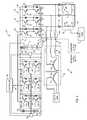
- FIG. 3shows a schematic diagram of a traction system 132 according to another embodiment of the invention. Elements and components common to traction systems 10 , 98 and 132 will be discussed relative to the same reference numbers as appropriate.
- high-impedance voltage source 62includes a plurality of primary windings 134 coupled to secondary windings 80 . Primary windings 134 may be coupled to the utility grid. A plurality of inductors 136 is coupled to secondary windings 80 . It is to be understood that high-impedance voltage source 62 as shown in FIG. 3 is applicable to the high-impedance voltage sources 62 shown in FIGS. 1 and 2 .
- High-impedance voltage source 62is coupled to bi-directional DC-to-AC voltage inverter 14 .
- plug 74is coupled to bi-directional DC-to-AC voltage inverter 14 between diodes 82 - 86 and windings 44 - 48 .
- a plurality of switches or contactors 138is coupled to windings 44 - 48 such that, during a re-charging operation when charging system 60 is coupled to traction system 132 , motor 40 may be de-coupled therefrom so that the charging energy does not electrically excite or supply energy to motor 40 and therefore motor 40 does not cause the vehicle to move during charging.
- charging system 60does not have a separate rectifier 66 . Instead, diodes 82 - 92 provide the rectification to convert the AC power supplied via high-impedance voltage source 62 to DC power for charge bus 16 . In this embodiment, all diodes 82 - 92 are rated to allow current from the charging energy on charge bus 16 to flow directly into first or second energy storage devices 12 , 100 during the first stage.
- charging energyflows from high-impedance voltage source 62 through diodes 82 - 92 to charge bus 16 during a first stage of the re-charging operation.
- the charging energy from charge bus 16flows into first energy storage device 12 and into second energy storage device 100 , as described below.
- Controller 56monitors and compares the monitored charging energy as described above to independently determine when to change the re-charging operation to the second stage for each energy storage device 12 , 100 .
- a plurality of inductors 140may be included to assist the transformer leakage inductance, represented by windings 136 , during the boosting operations if desired. It is contemplated that traction systems 10 , 98 or FIGS. 1 and 2 may also include inductors 140 to assist transformer leakage inductance during the boosting operations if desired.
- contactor 122If contactor 122 is open and contactor 128 is closed, then energy storage device 12 is charged directly from high-impedance voltage source 62 while energy storage device 100 is charged by bi-directional converters 102 , 104 , and 106 operating in buck mode, thus both energy storage device 12 and 100 can be charged simultaneously. If contactor 128 is open and contactor 122 is closed, then energy storage device 100 is charged directly from high-impedance voltage source 62 just as described above in FIG. 2 during stage 1 . When stage 2 is entered, contactor 122 opens, and stage 2 continues with the bi-directional converters 102 , 104 , and 106 controlling charge while operating in a buck mode.
- Energy storage device 12could then be charged at a later time either from high-impedance voltage source 62 with contactor 122 open and contactor 128 closed or, if the high-impedance voltage source 62 is unplugged from traction system 132 , directly from energy storage device 100 (which typically has significantly more energy than energy storage device 12 ) through bidirectional converters 102 , 104 , and 106 operating in boost mode.
- Bi-directional converters 102 , 104 , and 106can be operated with their switching phases shifted so as to reduce voltage and current ripple levels in both energy storage devices.
- controller 56operates DC-AC inverter 14 to control or regulate voltage on DC charge bus 16 to a threshold value as sensed using voltage sensor 130 using energy supplied by AC voltage source 62 .
- Energy storage device 100is capable of simultaneously being charged through control of bidirectional converters 102 , 104 , and 106 , or a subset thereof, operating in the buck mode.
- Embodiments of the inventionthus use components such as inverters, converters, filters and/or machine inductance already on-board a traction control system to recharge one or more energy storage devices of the traction control system. In this manner, these components may be used for the dual purposes of motoring and recharging the energy storage devices.
- Using the on-board components of the vehiclesallows for off-board charging stations to have a simple, low cost, high-power design. In addition, a high-current charging may be obtained in a cost effective manner.
- Rapid, fast charging of the on-board energy storage devicesmay be thus accomplished such that a large current flows into the energy storage devices in a first re-charging stage that is mainly limited by impedance of a voltage transformer without initial current control by electronic switching elements having higher current limiting properties.
- a technical contribution for the disclosed apparatusis that it provides for a controller implemented technique for transferring energy using onboard power electronics.
- an apparatuscomprises a first energy storage device configured to output a DC voltage, a first bi-directional voltage modification assembly coupled to the first energy storage device, and a charge bus coupled to the first energy storage device and to the first bi-directional voltage modification assembly.
- the apparatusalso comprises high-impedance voltage source coupleable to the charge bus and a controller configured to monitor a transfer of charging energy supplied from the high-impedance voltage source to the first energy storage device.
- the controlleris also configured to compare the monitored transfer of charging energy with a threshold value and, after the threshold value has been crossed, control the first bi-directional voltage modification assembly to modify one of a voltage and a current of the charging energy supplied to the first energy storage device.
- a methodcomprises coupling a battery to a first voltage bus, the battery configured to output a DC voltage, coupling a first bi-directional voltage modification assembly to the first voltage bus and coupling a second voltage bus to the first voltage bus, the second voltage bus configured to receive charging energy from a high-impedance voltage source and to supply the charging energy to one of the first bi-directional voltage modification assembly and the first voltage bus.
- the methodalso comprises configuring a controller to monitor a transfer of the charging energy to the battery, compare the monitored transfer of charging energy with a threshold value, and, after the threshold value has been crossed, control the first bi-directional voltage modification assembly to modify one of a voltage and a current of the charging energy supplied to the battery.
- a systemcomprises a charge bus configured to receive charging energy from a voltage source, an energy storage device configured to output a DC voltage and coupled to the charge bus, a first bi-directional voltage modification assembly coupled to the charge bus and a controller.
- the controlleris configured to monitor a transfer of the charging energy supplied to the energy storage device, compare the monitored transfer of charging energy with a threshold comprising one of a voltage of the energy storage device and an average rectified line voltage of the charge bus, and, after the threshold has been crossed, control the first bi-directional voltage modification assembly to modify one of a voltage and a current of the charging energy supplied to the first energy storage device.
Landscapes
- Engineering & Computer Science (AREA)
- Power Engineering (AREA)
- Transportation (AREA)
- Mechanical Engineering (AREA)
- Charge And Discharge Circuits For Batteries Or The Like (AREA)
- Electric Propulsion And Braking For Vehicles (AREA)
- Secondary Cells (AREA)
Abstract
Description
Claims (24)
Priority Applications (6)
| Application Number | Priority Date | Filing Date | Title |
|---|---|---|---|
| US12/550,504US8030884B2 (en) | 2009-08-31 | 2009-08-31 | Apparatus for transferring energy using onboard power electronics and method of manufacturing same |
| EP10174013.2AEP2290778B1 (en) | 2009-08-31 | 2010-08-25 | Apparatus for transferring energy using onboard power electronics |
| CN201010277436.7ACN102005789B (en) | 2009-08-31 | 2010-08-31 | Apparatus for transferring energy using onboard power electronics and method of manufacturing same |
| JP2010193001AJP6068778B2 (en) | 2009-08-31 | 2010-08-31 | Device for transmitting energy using in-vehicle power electronics and method of manufacturing the same |
| US13/099,053US8487582B2 (en) | 2009-08-31 | 2011-05-02 | Apparatus for transferring energy using onboard power electronics and method of manufacturing same |
| JP2015230270AJP6228586B2 (en) | 2009-08-31 | 2015-11-26 | Electric vehicle |
Applications Claiming Priority (1)
| Application Number | Priority Date | Filing Date | Title |
|---|---|---|---|
| US12/550,504US8030884B2 (en) | 2009-08-31 | 2009-08-31 | Apparatus for transferring energy using onboard power electronics and method of manufacturing same |
Related Child Applications (1)
| Application Number | Title | Priority Date | Filing Date |
|---|---|---|---|
| US13/099,053ContinuationUS8487582B2 (en) | 2009-08-31 | 2011-05-02 | Apparatus for transferring energy using onboard power electronics and method of manufacturing same |
Publications (2)
| Publication Number | Publication Date |
|---|---|
| US20110050173A1 US20110050173A1 (en) | 2011-03-03 |
| US8030884B2true US8030884B2 (en) | 2011-10-04 |
Family
ID=43479229
Family Applications (2)
| Application Number | Title | Priority Date | Filing Date |
|---|---|---|---|
| US12/550,504Active2029-10-30US8030884B2 (en) | 2009-08-31 | 2009-08-31 | Apparatus for transferring energy using onboard power electronics and method of manufacturing same |
| US13/099,053Active2029-12-16US8487582B2 (en) | 2009-08-31 | 2011-05-02 | Apparatus for transferring energy using onboard power electronics and method of manufacturing same |
Family Applications After (1)
| Application Number | Title | Priority Date | Filing Date |
|---|---|---|---|
| US13/099,053Active2029-12-16US8487582B2 (en) | 2009-08-31 | 2011-05-02 | Apparatus for transferring energy using onboard power electronics and method of manufacturing same |
Country Status (4)
| Country | Link |
|---|---|
| US (2) | US8030884B2 (en) |
| EP (1) | EP2290778B1 (en) |
| JP (2) | JP6068778B2 (en) |
| CN (1) | CN102005789B (en) |
Cited By (28)
| Publication number | Priority date | Publication date | Assignee | Title |
|---|---|---|---|---|
| US20120025753A1 (en)* | 2010-07-28 | 2012-02-02 | Jack Yajie Chen | Multiple Stage Heterogeneous High Power Battery System for Hybrid and Electric Vehicle |
| US20120262966A1 (en)* | 2010-01-11 | 2012-10-18 | Koninklijke Philips Electronics N.V. | Ac/dc converter circuit |
| US20130119932A1 (en)* | 2011-09-02 | 2013-05-16 | Mando Corporation | Battery charging apparatus |
| US20130193917A1 (en)* | 2010-08-30 | 2013-08-01 | Toyota Jidosha Kabushiki Kaisha | Charging device and charging method for power storage device |
| US20140070770A1 (en)* | 2011-02-14 | 2014-03-13 | Kabushiki Kaisha Toshiba | Electric energy storage device and installation-operation method thereof |
| US20140239885A1 (en)* | 2013-02-27 | 2014-08-28 | System General Corporation | Control circuit for charging battery through programmable power supplier |
| US20140368160A1 (en)* | 2012-01-20 | 2014-12-18 | Dirk Reichow | Vehicle Electric System, Device for Controlling a Vehicle Electric System, and Vehicle with a Device |
| US20150137751A1 (en)* | 2013-11-20 | 2015-05-21 | General Electric Company | Apparatus for rapid charging using onboard power electronics and method of manufacturing same |
| US9120390B2 (en) | 2012-03-08 | 2015-09-01 | General Electric Company | Apparatus for transferring energy using onboard power electronics and method of manufacturing same |
| US9174525B2 (en) | 2013-02-25 | 2015-11-03 | Fairfield Manufacturing Company, Inc. | Hybrid electric vehicle |
| US9236755B2 (en)* | 2012-05-17 | 2016-01-12 | Delta Electronics, Inc. | Charging system for reducing harmonic wave and fabricating cost |
| US9321364B1 (en) | 2015-06-30 | 2016-04-26 | Proterra Inc. | Heated charging interface of electric vehicle |
| US20160329846A1 (en)* | 2013-07-02 | 2016-11-10 | Mitsubishi Electric Corporation | Backflow preventing device, power conversion apparatus, and refrigerating and air-conditioning apparatus |
| US9520741B2 (en) | 2011-11-28 | 2016-12-13 | General Electric Company | System for charging electrical storage device and method of making same |
| US9643513B2 (en) | 2014-12-08 | 2017-05-09 | General Electric Company | Propelling system and energy management system and methods |
| US20170244337A1 (en)* | 2016-02-24 | 2017-08-24 | Honda Motor Co., Ltd. | Power supply system, apparatus, and control method |
| EP3238979A1 (en) | 2016-04-25 | 2017-11-01 | General Electric Company | Integrated charger for vehicles and method of making same |
| US9821668B2 (en) | 2012-05-21 | 2017-11-21 | General Electric Company | Method and apparatus for charging multiple energy storage devices |
| US10270265B2 (en) | 2014-03-26 | 2019-04-23 | New Fryer Industries Canada ULC | Controlling batteries for electric bus |
| US10377251B2 (en) | 2015-03-26 | 2019-08-13 | Proterra Inc. | Electric vehicle charging interface |
| US10454290B2 (en) | 2010-11-05 | 2019-10-22 | General Electric Company | Apparatus for transferring energy using onboard power electronics with high-frequency transformer isolation and method of manufacturing same |
| US10505439B2 (en) | 2017-10-09 | 2019-12-10 | Dr. Ing. H.C. F. Porsche Aktiengesellschaft | Inverter for an electric automobile |
| US10666045B2 (en) | 2011-10-28 | 2020-05-26 | General Electric Company | System for selectively coupling an energy source to a load and method of making same |
| US10771001B2 (en) | 2015-09-11 | 2020-09-08 | Invertedpower Pty Ltd | Controller for an inductive load having one or more inductive windings |
| US11053096B2 (en) | 2017-08-28 | 2021-07-06 | Otis Elevator Company | Automatic rescue and charging system for elevator drive |
| US11458852B2 (en)* | 2020-05-14 | 2022-10-04 | Cummins Inc. | DC-DC converter control |
| US11511637B2 (en) | 2019-05-24 | 2022-11-29 | Huawei Digital Power Technologies Co., Ltd. | Integrated charger and motor control system |
| US11738653B2 (en) | 2019-11-22 | 2023-08-29 | Huawei Digital Power Technologies Co., Ltd. | Integrated charger and motor control system isolated by motor |
Families Citing this family (33)
| Publication number | Priority date | Publication date | Assignee | Title |
|---|---|---|---|---|
| WO2011031267A2 (en)* | 2009-09-11 | 2011-03-17 | Tm Ge Automation Systems, Llc | Fuel efficient crane system |
| US8698451B2 (en) | 2009-12-18 | 2014-04-15 | General Electric Company | Apparatus and method for rapid charging using shared power electronics |
| KR101004498B1 (en)* | 2010-01-25 | 2010-12-31 | 엘에스산전 주식회사 | Charging device |
| DE102010048985A1 (en)* | 2010-10-20 | 2012-04-26 | Li-Tec Battery Gmbh | Battery management system for power supply system with low voltage range and high voltage range |
| CN202019221U (en)* | 2011-04-18 | 2011-10-26 | 成都秦川科技发展有限公司 | PWM (Pulse-Width Modulation) rectifying and variable-voltage variable-current pulse charging system for electric vehicle |
| US9399402B2 (en) | 2011-04-21 | 2016-07-26 | Lear Corporation | Proximity detection circuit for on-board vehicle charger |
| DE102011079359A1 (en)* | 2011-07-18 | 2013-01-24 | Bayerische Motoren Werke Aktiengesellschaft | Charger with auxiliary power supply |
| US9211798B2 (en)* | 2011-07-28 | 2015-12-15 | Lear Corporation | Multistage power supply system and method for providing uninterrupted power to vehicle circuitry |
| US9233611B2 (en) | 2011-11-10 | 2016-01-12 | Lear Corporation | Proximity detection circuit having short protection |
| US9440538B2 (en) | 2011-11-11 | 2016-09-13 | Lear Corporation | Housekeeping circuit having trickle charge capabilities |
| JP5483221B2 (en)* | 2011-12-05 | 2014-05-07 | トヨタ自動車株式会社 | Fuel cell vehicle |
| EP2802055B1 (en) | 2011-12-31 | 2019-06-26 | Shenzhen BYD Auto R&D Company Limited | Electric vehicle and active discharge system for electric vehicle |
| US20140253085A1 (en)* | 2013-03-11 | 2014-09-11 | Chung Shan Institute Of Science And Technology, Armaments Bureau, M.N.D | Digital programmable control systems |
| CN104249629B (en) | 2013-06-28 | 2016-09-07 | 比亚迪股份有限公司 | Electric automobile, the dynamical system of electric automobile and the charging method of electrokinetic cell |
| CN104753402B (en)* | 2013-12-25 | 2017-08-25 | 台达电子工业股份有限公司 | generator braking system and control method thereof |
| CN103840721A (en)* | 2014-03-25 | 2014-06-04 | 哈尔滨中科盛普科技有限公司 | Oil-immersed screw pump servo driving system and driving method thereof |
| US9827865B2 (en) | 2014-12-30 | 2017-11-28 | General Electric Company | Systems and methods for recharging vehicle-mounted energy storage devices |
| CN104578327A (en)* | 2015-02-11 | 2015-04-29 | 国网上海市电力公司 | Smart charging and discharging motor main circuit |
| US10300804B2 (en) | 2015-04-29 | 2019-05-28 | General Electric Company | Apparatus and method for automated positioning of a vehicle |
| US10044209B2 (en)* | 2015-12-01 | 2018-08-07 | GM Global Technology Operations LLC | Method and apparatus for charging a high-voltage battery assembly |
| US9987938B2 (en) | 2015-12-04 | 2018-06-05 | General Electric Company | Energy storage device, exchange apparatus, and method for exchanging an energy storage device |
| JP6461838B2 (en)* | 2016-02-24 | 2019-01-30 | 本田技研工業株式会社 | Power supply device, device and control method |
| DE102016218304B3 (en)* | 2016-09-23 | 2018-02-01 | Volkswagen Aktiengesellschaft | Device for voltage conversion, traction network and method for charging a battery |
| FR3060906B1 (en)* | 2016-12-16 | 2019-05-24 | Ge Energy Power Conversion Technology Limited | CONTINUOUS-ALTERNATIVE CONVERTER |
| DE102017123346A1 (en)* | 2017-10-09 | 2019-04-11 | Dr. Ing. H.C. F. Porsche Aktiengesellschaft | A method for initializing a DC charging of a battery by means of an inverter |
| KR101890247B1 (en)* | 2018-04-26 | 2018-08-21 | 주식회사 경신 | Power converting apparatus performing function of inverter |
| US10989027B2 (en)* | 2018-07-27 | 2021-04-27 | Upwing Energy, LLC | Artificial lift |
| US10914149B2 (en) | 2018-08-29 | 2021-02-09 | Upwing Energy, LLC | Artificial lift |
| WO2020248023A1 (en) | 2019-06-12 | 2020-12-17 | Invertedpower Pty Ltd | An electric vehicle dc-dc boost converter |
| KR102796848B1 (en)* | 2019-08-06 | 2025-04-17 | 현대자동차주식회사 | System and method for charging using motor driving system |
| EP4122073A4 (en)* | 2020-10-30 | 2023-12-27 | Velocity Magnetics, Inc. | Insulated-gate bipolar transistor (igbt) rectifier for charging ultra-capacitors |
| CN112600411A (en)* | 2020-12-14 | 2021-04-02 | 蔚来汽车科技(安徽)有限公司 | Voltage conversion device, electric drive system and vehicle |
| US11811303B2 (en) | 2021-09-24 | 2023-11-07 | Apple Inc. | Decoupling device using stored charge reverse recovery |
Citations (9)
| Publication number | Priority date | Publication date | Assignee | Title |
|---|---|---|---|---|
| US5373195A (en) | 1992-12-23 | 1994-12-13 | General Electric Company | Technique for decoupling the energy storage system voltage from the DC link voltage in AC electric drive systems |
| US5589743A (en)* | 1995-03-03 | 1996-12-31 | General Electric Company | Integrated cranking inverter and boost converter for a series hybrid drive system |
| US5903449A (en) | 1998-06-09 | 1999-05-11 | General Electric Company | Bi-directional power control system for voltage converter |
| US6331365B1 (en) | 1998-11-12 | 2001-12-18 | General Electric Company | Traction motor drive system |
| US20020051368A1 (en)* | 2000-02-14 | 2002-05-02 | Ulinski Richard J. | Mobile power generation system |
| US20070012492A1 (en)* | 2005-06-22 | 2007-01-18 | Duo Deng | Power generation system suitable for hybrid electric vehicles |
| US7499296B2 (en)* | 2004-09-27 | 2009-03-03 | Mge Ups Systems | Electric power converter device with control means and process and converting power |
| US7595597B2 (en)* | 2006-01-18 | 2009-09-29 | General Electric Comapany | Vehicle propulsion system |
| US7750501B2 (en)* | 2005-10-27 | 2010-07-06 | Continental Automotive Systems Us, Inc. | System and method of over voltage control for a power system |
Family Cites Families (26)
| Publication number | Priority date | Publication date | Assignee | Title |
|---|---|---|---|---|
| JPS5961402A (en)* | 1982-09-30 | 1984-04-07 | Toshiba Corp | Charging device for battery powered vehicles |
| US5132604A (en)* | 1989-04-04 | 1992-07-21 | Honda Giken Kogyo Kabushiki Kaisha | Engine starter and electric generator system |
| JPH04275002A (en)* | 1991-03-04 | 1992-09-30 | Toyota Motor Corp | Electric vehicle charging device |
| JP3284571B2 (en)* | 1992-01-24 | 2002-05-20 | 株式会社明電舎 | Electric car |
| JPH06178407A (en)* | 1992-12-08 | 1994-06-24 | Kyushu Electric Power Co Inc | Vehicle-borne charger for electric vehicle |
| JPH06292304A (en)* | 1993-04-05 | 1994-10-18 | Yaskawa Electric Corp | Electric power converter in electric vehicle drive system |
| JPH08107608A (en)* | 1994-10-04 | 1996-04-23 | Kansai Electric Power Co Inc:The | Battery charger / motor drive device and electric vehicle |
| JP3477850B2 (en)* | 1994-10-26 | 2003-12-10 | 株式会社明電舎 | Electric vehicle charger |
| JP3277825B2 (en)* | 1996-10-25 | 2002-04-22 | トヨタ自動車株式会社 | Charging device |
| KR100262305B1 (en)* | 1997-08-25 | 2000-07-15 | 강병호 | Charging device for smart battery, charging method thereof and power supply device of notebook computer using same |
| JPH11266587A (en)* | 1998-03-16 | 1999-09-28 | Ebara Densan Ltd | AC-DC power conversion method and device |
| US6118678A (en)* | 1999-06-10 | 2000-09-12 | Limpaecher; Rudolf | Charge transfer apparatus and method therefore |
| EP1516406A2 (en)* | 2002-06-14 | 2005-03-23 | Koninklijke Philips Electronics N.V. | Charger for rechargeable batteries |
| JP2005033954A (en)* | 2003-07-09 | 2005-02-03 | Toyota Motor Corp | Battery charger |
| JP4337442B2 (en)* | 2003-07-31 | 2009-09-30 | 株式会社明電舎 | In-vehicle battery charger |
| JP2006050779A (en)* | 2004-08-04 | 2006-02-16 | Toyota Motor Corp | Motor driving device |
| JP4839722B2 (en)* | 2005-08-08 | 2011-12-21 | トヨタ自動車株式会社 | Vehicle power supply |
| JP4367391B2 (en)* | 2005-09-01 | 2009-11-18 | トヨタ自動車株式会社 | Charge control device and electric vehicle |
| JP2007336664A (en)* | 2006-06-14 | 2007-12-27 | Mitsumi Electric Co Ltd | Secondary battery charging circuit |
| JP2008199770A (en)* | 2007-02-13 | 2008-08-28 | Toyota Motor Corp | Power supply device and vehicle |
| FI120855B (en) | 2007-02-15 | 2010-03-31 | Kone Corp | Hardware and Method for Controlling Engine Power Supply |
| JP4894656B2 (en)* | 2007-07-13 | 2012-03-14 | トヨタ自動車株式会社 | vehicle |
| JP4367559B2 (en)* | 2007-08-10 | 2009-11-18 | トヨタ自動車株式会社 | vehicle |
| JP4305553B2 (en)* | 2007-10-23 | 2009-07-29 | トヨタ自動車株式会社 | Electric vehicle |
| KR100999969B1 (en)* | 2007-12-12 | 2010-12-09 | 현대자동차주식회사 | Battery charger |
| KR100848297B1 (en)* | 2007-12-24 | 2008-07-25 | (주)시그넷시스템 | Charger with integrated parallel operation and distributed control |
- 2009
- 2009-08-31USUS12/550,504patent/US8030884B2/enactiveActive
- 2010
- 2010-08-25EPEP10174013.2Apatent/EP2290778B1/enactiveActive
- 2010-08-31CNCN201010277436.7Apatent/CN102005789B/enactiveActive
- 2010-08-31JPJP2010193001Apatent/JP6068778B2/enactiveActive
- 2011
- 2011-05-02USUS13/099,053patent/US8487582B2/enactiveActive
- 2015
- 2015-11-26JPJP2015230270Apatent/JP6228586B2/enactiveActive
Patent Citations (11)
| Publication number | Priority date | Publication date | Assignee | Title |
|---|---|---|---|---|
| US5373195A (en) | 1992-12-23 | 1994-12-13 | General Electric Company | Technique for decoupling the energy storage system voltage from the DC link voltage in AC electric drive systems |
| US5589743A (en)* | 1995-03-03 | 1996-12-31 | General Electric Company | Integrated cranking inverter and boost converter for a series hybrid drive system |
| US5903449A (en) | 1998-06-09 | 1999-05-11 | General Electric Company | Bi-directional power control system for voltage converter |
| US6331365B1 (en) | 1998-11-12 | 2001-12-18 | General Electric Company | Traction motor drive system |
| US6737822B2 (en) | 1998-11-12 | 2004-05-18 | General Electric Company | Traction motor drive system |
| US7049792B2 (en) | 1998-11-12 | 2006-05-23 | General Electric Company | Method and apparatus for a hybrid battery configuration for use in an electric or hybrid electric motive power system |
| US20020051368A1 (en)* | 2000-02-14 | 2002-05-02 | Ulinski Richard J. | Mobile power generation system |
| US7499296B2 (en)* | 2004-09-27 | 2009-03-03 | Mge Ups Systems | Electric power converter device with control means and process and converting power |
| US20070012492A1 (en)* | 2005-06-22 | 2007-01-18 | Duo Deng | Power generation system suitable for hybrid electric vehicles |
| US7750501B2 (en)* | 2005-10-27 | 2010-07-06 | Continental Automotive Systems Us, Inc. | System and method of over voltage control for a power system |
| US7595597B2 (en)* | 2006-01-18 | 2009-09-29 | General Electric Comapany | Vehicle propulsion system |
Cited By (45)
| Publication number | Priority date | Publication date | Assignee | Title |
|---|---|---|---|---|
| US20120262966A1 (en)* | 2010-01-11 | 2012-10-18 | Koninklijke Philips Electronics N.V. | Ac/dc converter circuit |
| US9425703B2 (en)* | 2010-01-11 | 2016-08-23 | Koninklijke Philips N.V. | AC/DC converter circuit for common three-phase AC input voltages and method of operating such converter circuit |
| US8692507B2 (en)* | 2010-07-28 | 2014-04-08 | Jack Yajie Chen | Multiple stage heterogeneous high power battery system for hybrid and electric vehicle |
| US20120025753A1 (en)* | 2010-07-28 | 2012-02-02 | Jack Yajie Chen | Multiple Stage Heterogeneous High Power Battery System for Hybrid and Electric Vehicle |
| US20130193917A1 (en)* | 2010-08-30 | 2013-08-01 | Toyota Jidosha Kabushiki Kaisha | Charging device and charging method for power storage device |
| US9061596B2 (en)* | 2010-08-30 | 2015-06-23 | Toyota Jidosha Kabushiki Kaisha | Charging device and charging method for power storage device |
| US10454290B2 (en) | 2010-11-05 | 2019-10-22 | General Electric Company | Apparatus for transferring energy using onboard power electronics with high-frequency transformer isolation and method of manufacturing same |
| US20140070770A1 (en)* | 2011-02-14 | 2014-03-13 | Kabushiki Kaisha Toshiba | Electric energy storage device and installation-operation method thereof |
| US9312717B2 (en)* | 2011-02-14 | 2016-04-12 | Kabushiki Kaisha Toshiba | Electric energy storage device and installation-operation method thereof |
| US20130119932A1 (en)* | 2011-09-02 | 2013-05-16 | Mando Corporation | Battery charging apparatus |
| US10958069B2 (en) | 2011-10-28 | 2021-03-23 | General Electric Company | System for selectively coupling an energy source to a load and method of making same |
| US10666045B2 (en) | 2011-10-28 | 2020-05-26 | General Electric Company | System for selectively coupling an energy source to a load and method of making same |
| US9520741B2 (en) | 2011-11-28 | 2016-12-13 | General Electric Company | System for charging electrical storage device and method of making same |
| US20140368160A1 (en)* | 2012-01-20 | 2014-12-18 | Dirk Reichow | Vehicle Electric System, Device for Controlling a Vehicle Electric System, and Vehicle with a Device |
| US9731610B2 (en)* | 2012-01-20 | 2017-08-15 | Continental Automotive Gmbh | Vehicle electric system, device for controlling a vehicle electric system, and vehicle with a device |
| US9120390B2 (en) | 2012-03-08 | 2015-09-01 | General Electric Company | Apparatus for transferring energy using onboard power electronics and method of manufacturing same |
| US9236755B2 (en)* | 2012-05-17 | 2016-01-12 | Delta Electronics, Inc. | Charging system for reducing harmonic wave and fabricating cost |
| US10081257B2 (en) | 2012-05-21 | 2018-09-25 | General Electric Company | Method and apparatus for charging multiple energy storage devices |
| US10766372B2 (en) | 2012-05-21 | 2020-09-08 | General Electric Company | Method and apparatus for charging multiple energy storage devices |
| US11697352B2 (en) | 2012-05-21 | 2023-07-11 | General Electric Company | Method and apparatus for charging multiple energy storage devices |
| US11318852B2 (en) | 2012-05-21 | 2022-05-03 | General Electric Company | Method and apparatus for charging multiple energy storage devices |
| US9821668B2 (en) | 2012-05-21 | 2017-11-21 | General Electric Company | Method and apparatus for charging multiple energy storage devices |
| US10081258B2 (en) | 2012-05-21 | 2018-09-25 | General Electric Company | Method and apparatus for charging multiple energy storage devices |
| US9878607B2 (en) | 2013-02-25 | 2018-01-30 | Fairfield Manufacturing Company, Inc. | Hybrid electric vehicle |
| US9174525B2 (en) | 2013-02-25 | 2015-11-03 | Fairfield Manufacturing Company, Inc. | Hybrid electric vehicle |
| US9343917B2 (en)* | 2013-02-27 | 2016-05-17 | System General Corporation | Control circuit for charging battery through programmable power supplier |
| US20140239885A1 (en)* | 2013-02-27 | 2014-08-28 | System General Corporation | Control circuit for charging battery through programmable power supplier |
| US10404196B2 (en)* | 2013-07-02 | 2019-09-03 | Mitsubishi Electric Corporation | Backflow preventing device, power conversion apparatus, and refrigerating and air-conditioning apparatus |
| US20160329846A1 (en)* | 2013-07-02 | 2016-11-10 | Mitsubishi Electric Corporation | Backflow preventing device, power conversion apparatus, and refrigerating and air-conditioning apparatus |
| US9238415B2 (en)* | 2013-11-20 | 2016-01-19 | General Electric Company | Apparatus for rapid charging using onboard power electronics and method of manufacturing same |
| US20150137751A1 (en)* | 2013-11-20 | 2015-05-21 | General Electric Company | Apparatus for rapid charging using onboard power electronics and method of manufacturing same |
| US10270265B2 (en) | 2014-03-26 | 2019-04-23 | New Fryer Industries Canada ULC | Controlling batteries for electric bus |
| US9643513B2 (en) | 2014-12-08 | 2017-05-09 | General Electric Company | Propelling system and energy management system and methods |
| US10377251B2 (en) | 2015-03-26 | 2019-08-13 | Proterra Inc. | Electric vehicle charging interface |
| US9321364B1 (en) | 2015-06-30 | 2016-04-26 | Proterra Inc. | Heated charging interface of electric vehicle |
| US10771001B2 (en) | 2015-09-11 | 2020-09-08 | Invertedpower Pty Ltd | Controller for an inductive load having one or more inductive windings |
| US20170244337A1 (en)* | 2016-02-24 | 2017-08-24 | Honda Motor Co., Ltd. | Power supply system, apparatus, and control method |
| JP2017153243A (en)* | 2016-02-24 | 2017-08-31 | 本田技研工業株式会社 | Power supply device, device and control method |
| US10507716B2 (en) | 2016-04-25 | 2019-12-17 | General Electric Company | Integrated charger for vehicles and method of making same |
| EP3238979A1 (en) | 2016-04-25 | 2017-11-01 | General Electric Company | Integrated charger for vehicles and method of making same |
| US11053096B2 (en) | 2017-08-28 | 2021-07-06 | Otis Elevator Company | Automatic rescue and charging system for elevator drive |
| US10505439B2 (en) | 2017-10-09 | 2019-12-10 | Dr. Ing. H.C. F. Porsche Aktiengesellschaft | Inverter for an electric automobile |
| US11511637B2 (en) | 2019-05-24 | 2022-11-29 | Huawei Digital Power Technologies Co., Ltd. | Integrated charger and motor control system |
| US11738653B2 (en) | 2019-11-22 | 2023-08-29 | Huawei Digital Power Technologies Co., Ltd. | Integrated charger and motor control system isolated by motor |
| US11458852B2 (en)* | 2020-05-14 | 2022-10-04 | Cummins Inc. | DC-DC converter control |
Also Published As
| Publication number | Publication date |
|---|---|
| CN102005789B (en) | 2015-04-15 |
| JP6068778B2 (en) | 2017-01-25 |
| JP6228586B2 (en) | 2017-11-08 |
| JP2011055700A (en) | 2011-03-17 |
| CN102005789A (en) | 2011-04-06 |
| US8487582B2 (en) | 2013-07-16 |
| EP2290778B1 (en) | 2021-04-07 |
| JP2016106511A (en) | 2016-06-16 |
| US20110050173A1 (en) | 2011-03-03 |
| EP2290778A3 (en) | 2016-06-01 |
| US20110204854A1 (en) | 2011-08-25 |
| EP2290778A2 (en) | 2011-03-02 |
Similar Documents
| Publication | Publication Date | Title |
|---|---|---|
| US8030884B2 (en) | Apparatus for transferring energy using onboard power electronics and method of manufacturing same | |
| US12384260B2 (en) | Apparatus and method for rapid charging using shared power electronics | |
| US8421271B2 (en) | Apparatus for transferring energy using onboard power electronics and method of manufacturing same | |
| US9120390B2 (en) | Apparatus for transferring energy using onboard power electronics and method of manufacturing same | |
| US11167654B2 (en) | Apparatus for transferring energy using power electronics and machine inductance and method of manufacturing same | |
| US10454290B2 (en) | Apparatus for transferring energy using onboard power electronics with high-frequency transformer isolation and method of manufacturing same | |
| EP2875984B1 (en) | Apparatus for rapid charging using onboard power electronics and method of manufacturing same | |
| JP6924061B2 (en) | Traction system | |
| JP6659203B2 (en) | System for transferring energy from an energy source and method of manufacturing the same |
Legal Events
| Date | Code | Title | Description |
|---|---|---|---|
| AS | Assignment | Owner name:GENERAL ELECTRIC COMPANY, NEW YORK Free format text:ASSIGNMENT OF ASSIGNORS INTEREST;ASSIGNORS:KING, ROBERT DEAN;STEIGERWALD, ROBERT LOUIS;SIGNING DATES FROM 20090828 TO 20090829;REEL/FRAME:023169/0396 | |
| STCF | Information on status: patent grant | Free format text:PATENTED CASE | |
| FPAY | Fee payment | Year of fee payment:4 | |
| MAFP | Maintenance fee payment | Free format text:PAYMENT OF MAINTENANCE FEE, 8TH YEAR, LARGE ENTITY (ORIGINAL EVENT CODE: M1552); ENTITY STATUS OF PATENT OWNER: LARGE ENTITY Year of fee payment:8 | |
| MAFP | Maintenance fee payment | Free format text:PAYMENT OF MAINTENANCE FEE, 12TH YEAR, LARGE ENTITY (ORIGINAL EVENT CODE: M1553); ENTITY STATUS OF PATENT OWNER: LARGE ENTITY Year of fee payment:12 | |
| AS | Assignment | Owner name:EDISON INNOVATIONS, LLC, TEXAS Free format text:ASSIGNMENT OF ASSIGNORS INTEREST;ASSIGNOR:DOLBY INTELLECTUAL PROPERTY LICENSING, LLC;REEL/FRAME:070293/0273 Effective date:20250219 | |
| AS | Assignment | Owner name:GE INTELLECTUAL PROPERTY LICENSING, LLC, NEW YORK Free format text:ASSIGNMENT OF ASSIGNORS INTEREST;ASSIGNOR:GENERAL ELECTRIC COMPANY;REEL/FRAME:070636/0815 Effective date:20240630 Owner name:DOLBY INTELLECTUAL PROPERTY LICENSING, LLC, NEW YORK Free format text:CHANGE OF NAME;ASSIGNOR:GE INTELLECTUAL PROPERTY LICENSING, LLC;REEL/FRAME:070643/0907 Effective date:20240819 |