US8029746B2 - Instrument for cassette for sample preparation - Google Patents
Instrument for cassette for sample preparationDownload PDFInfo
- Publication number
- US8029746B2 US8029746B2US13/044,109US201113044109AUS8029746B2US 8029746 B2US8029746 B2US 8029746B2US 201113044109 AUS201113044109 AUS 201113044109AUS 8029746 B2US8029746 B2US 8029746B2
- Authority
- US
- United States
- Prior art keywords
- chamber
- cassette
- reagent
- actuator assembly
- protrusions
- Prior art date
- Legal status (The legal status is an assumption and is not a legal conclusion. Google has not performed a legal analysis and makes no representation as to the accuracy of the status listed.)
- Active
Links
- 238000002360preparation methodMethods0.000titledescription8
- 239000003153chemical reaction reagentSubstances0.000claimsabstractdescription77
- 238000012546transferMethods0.000claimsabstractdescription44
- 239000002245particleSubstances0.000claimsdescription28
- 238000010438heat treatmentMethods0.000claimsdescription23
- 238000005086pumpingMethods0.000abstractdescription35
- 239000006249magnetic particleSubstances0.000abstractdescription24
- 238000012545processingMethods0.000abstractdescription19
- UHZZMRAGKVHANO-UHFFFAOYSA-Mchlormequat chlorideChemical compound[Cl-].C[N+](C)(C)CCClUHZZMRAGKVHANO-UHFFFAOYSA-M0.000abstractdescription17
- 239000011534wash bufferSubstances0.000abstractdescription17
- 238000001514detection methodMethods0.000abstractdescription12
- 239000000243solutionSubstances0.000description58
- 239000000523sampleSubstances0.000description35
- 239000011324beadSubstances0.000description30
- 238000005406washingMethods0.000description29
- 102000039446nucleic acidsHuman genes0.000description26
- 108020004707nucleic acidsProteins0.000description26
- 150000007523nucleic acidsChemical class0.000description26
- 238000010828elutionMethods0.000description23
- 108010067770Endopeptidase KProteins0.000description17
- 230000009089cytolysisEffects0.000description11
- 230000000712assemblyEffects0.000description9
- 238000000429assemblyMethods0.000description9
- 210000004027cellAnatomy0.000description9
- 238000000034methodMethods0.000description9
- 238000010586diagramMethods0.000description8
- 239000000203mixtureSubstances0.000description8
- 239000010409thin filmSubstances0.000description8
- 238000004891communicationMethods0.000description7
- 230000004913activationEffects0.000description6
- 230000007246mechanismEffects0.000description5
- 238000003860storageMethods0.000description5
- XEEYBQQBJWHFJM-UHFFFAOYSA-NIronChemical compound[Fe]XEEYBQQBJWHFJM-UHFFFAOYSA-N0.000description4
- 239000004973liquid crystal related substanceSubstances0.000description4
- 230000014759maintenance of locationEffects0.000description4
- 230000008569processEffects0.000description4
- 239000013590bulk materialSubstances0.000description3
- 238000001816coolingMethods0.000description3
- 239000012149elution bufferSubstances0.000description2
- 230000002209hydrophobic effectEffects0.000description2
- 229910052742ironInorganic materials0.000description2
- 230000033001locomotionEffects0.000description2
- 230000003287optical effectEffects0.000description2
- 150000003839saltsChemical class0.000description2
- 241000894006BacteriaSpecies0.000description1
- 108090000790EnzymesProteins0.000description1
- 102000004190EnzymesHuman genes0.000description1
- 240000004808Saccharomyces cerevisiaeSpecies0.000description1
- 239000012472biological sampleSubstances0.000description1
- 239000008280bloodSubstances0.000description1
- 210000004369bloodAnatomy0.000description1
- 239000000356contaminantSubstances0.000description1
- 238000011109contaminationMethods0.000description1
- 238000007796conventional methodMethods0.000description1
- 230000008878couplingEffects0.000description1
- 238000010168coupling processMethods0.000description1
- 238000005859coupling reactionMethods0.000description1
- 239000003599detergentSubstances0.000description1
- 230000006870functionEffects0.000description1
- 230000002068genetic effectEffects0.000description1
- 210000004209hairAnatomy0.000description1
- 210000005260human cellAnatomy0.000description1
- 238000003475laminationMethods0.000description1
- 239000007788liquidSubstances0.000description1
- 239000012139lysis bufferSubstances0.000description1
- 238000004519manufacturing processMethods0.000description1
- 239000011159matrix materialSubstances0.000description1
- 239000012528membraneSubstances0.000description1
- 238000012986modificationMethods0.000description1
- 230000004048modificationEffects0.000description1
- 230000006855networkingEffects0.000description1
- 239000002547new drugSubstances0.000description1
- 239000002773nucleotideSubstances0.000description1
- 125000003729nucleotide groupChemical group0.000description1
- 230000002093peripheral effectEffects0.000description1
- 230000000644propagated effectEffects0.000description1
- 108090000623proteins and genesProteins0.000description1
- 102000004169proteins and genesHuman genes0.000description1
- 238000007789sealingMethods0.000description1
- 230000011664signalingEffects0.000description1
- 230000003068static effectEffects0.000description1
- 230000001360synchronised effectEffects0.000description1
- 210000002700urineAnatomy0.000description1
Images


Classifications
- G—PHYSICS
- G01—MEASURING; TESTING
- G01N—INVESTIGATING OR ANALYSING MATERIALS BY DETERMINING THEIR CHEMICAL OR PHYSICAL PROPERTIES
- G01N35/00—Automatic analysis not limited to methods or materials provided for in any single one of groups G01N1/00 - G01N33/00; Handling materials therefor
- G01N35/08—Automatic analysis not limited to methods or materials provided for in any single one of groups G01N1/00 - G01N33/00; Handling materials therefor using a stream of discrete samples flowing along a tube system, e.g. flow injection analysis
- C—CHEMISTRY; METALLURGY
- C12—BIOCHEMISTRY; BEER; SPIRITS; WINE; VINEGAR; MICROBIOLOGY; ENZYMOLOGY; MUTATION OR GENETIC ENGINEERING
- C12Q—MEASURING OR TESTING PROCESSES INVOLVING ENZYMES, NUCLEIC ACIDS OR MICROORGANISMS; COMPOSITIONS OR TEST PAPERS THEREFOR; PROCESSES OF PREPARING SUCH COMPOSITIONS; CONDITION-RESPONSIVE CONTROL IN MICROBIOLOGICAL OR ENZYMOLOGICAL PROCESSES
- C12Q1/00—Measuring or testing processes involving enzymes, nucleic acids or microorganisms; Compositions therefor; Processes of preparing such compositions
- C12Q1/68—Measuring or testing processes involving enzymes, nucleic acids or microorganisms; Compositions therefor; Processes of preparing such compositions involving nucleic acids
- C12Q1/6806—Preparing nucleic acids for analysis, e.g. for polymerase chain reaction [PCR] assay
- B—PERFORMING OPERATIONS; TRANSPORTING
- B01—PHYSICAL OR CHEMICAL PROCESSES OR APPARATUS IN GENERAL
- B01L—CHEMICAL OR PHYSICAL LABORATORY APPARATUS FOR GENERAL USE
- B01L3/00—Containers or dishes for laboratory use, e.g. laboratory glassware; Droppers
- B01L3/50—Containers for the purpose of retaining a material to be analysed, e.g. test tubes
- B01L3/502—Containers for the purpose of retaining a material to be analysed, e.g. test tubes with fluid transport, e.g. in multi-compartment structures
- B—PERFORMING OPERATIONS; TRANSPORTING
- B01—PHYSICAL OR CHEMICAL PROCESSES OR APPARATUS IN GENERAL
- B01L—CHEMICAL OR PHYSICAL LABORATORY APPARATUS FOR GENERAL USE
- B01L3/00—Containers or dishes for laboratory use, e.g. laboratory glassware; Droppers
- B01L3/52—Containers specially adapted for storing or dispensing a reagent
- B01L3/527—Containers specially adapted for storing or dispensing a reagent for a plurality of reagents
- C—CHEMISTRY; METALLURGY
- C12—BIOCHEMISTRY; BEER; SPIRITS; WINE; VINEGAR; MICROBIOLOGY; ENZYMOLOGY; MUTATION OR GENETIC ENGINEERING
- C12N—MICROORGANISMS OR ENZYMES; COMPOSITIONS THEREOF; PROPAGATING, PRESERVING, OR MAINTAINING MICROORGANISMS; MUTATION OR GENETIC ENGINEERING; CULTURE MEDIA
- C12N15/00—Mutation or genetic engineering; DNA or RNA concerning genetic engineering, vectors, e.g. plasmids, or their isolation, preparation or purification; Use of hosts therefor
- C12N15/09—Recombinant DNA-technology
- C12N15/10—Processes for the isolation, preparation or purification of DNA or RNA
- C12N15/1003—Extracting or separating nucleic acids from biological samples, e.g. pure separation or isolation methods; Conditions, buffers or apparatuses therefor
- C12N15/1006—Extracting or separating nucleic acids from biological samples, e.g. pure separation or isolation methods; Conditions, buffers or apparatuses therefor by means of a solid support carrier, e.g. particles, polymers
- C12N15/1013—Extracting or separating nucleic acids from biological samples, e.g. pure separation or isolation methods; Conditions, buffers or apparatuses therefor by means of a solid support carrier, e.g. particles, polymers by using magnetic beads
- G—PHYSICS
- G01—MEASURING; TESTING
- G01N—INVESTIGATING OR ANALYSING MATERIALS BY DETERMINING THEIR CHEMICAL OR PHYSICAL PROPERTIES
- G01N35/00—Automatic analysis not limited to methods or materials provided for in any single one of groups G01N1/00 - G01N33/00; Handling materials therefor
- G01N35/00584—Control arrangements for automatic analysers
- G01N35/00722—Communications; Identification
- G01N35/00871—Communications between instruments or with remote terminals
- G—PHYSICS
- G01—MEASURING; TESTING
- G01N—INVESTIGATING OR ANALYSING MATERIALS BY DETERMINING THEIR CHEMICAL OR PHYSICAL PROPERTIES
- G01N35/00—Automatic analysis not limited to methods or materials provided for in any single one of groups G01N1/00 - G01N33/00; Handling materials therefor
- G01N35/0098—Automatic analysis not limited to methods or materials provided for in any single one of groups G01N1/00 - G01N33/00; Handling materials therefor involving analyte bound to insoluble magnetic carrier, e.g. using magnetic separation
- G—PHYSICS
- G01—MEASURING; TESTING
- G01N—INVESTIGATING OR ANALYSING MATERIALS BY DETERMINING THEIR CHEMICAL OR PHYSICAL PROPERTIES
- G01N35/00—Automatic analysis not limited to methods or materials provided for in any single one of groups G01N1/00 - G01N33/00; Handling materials therefor
- G01N35/02—Automatic analysis not limited to methods or materials provided for in any single one of groups G01N1/00 - G01N33/00; Handling materials therefor using a plurality of sample containers moved by a conveyor system past one or more treatment or analysis stations
- G01N35/028—Automatic analysis not limited to methods or materials provided for in any single one of groups G01N1/00 - G01N33/00; Handling materials therefor using a plurality of sample containers moved by a conveyor system past one or more treatment or analysis stations having reaction cells in the form of microtitration plates
- B—PERFORMING OPERATIONS; TRANSPORTING
- B01—PHYSICAL OR CHEMICAL PROCESSES OR APPARATUS IN GENERAL
- B01F—MIXING, e.g. DISSOLVING, EMULSIFYING OR DISPERSING
- B01F35/00—Accessories for mixers; Auxiliary operations or auxiliary devices; Parts or details of general application
- B01F35/71—Feed mechanisms
- B01F35/717—Feed mechanisms characterised by the means for feeding the components to the mixer
- B01F35/7174—Feed mechanisms characterised by the means for feeding the components to the mixer using pistons, plungers or syringes
- B—PERFORMING OPERATIONS; TRANSPORTING
- B01—PHYSICAL OR CHEMICAL PROCESSES OR APPARATUS IN GENERAL
- B01L—CHEMICAL OR PHYSICAL LABORATORY APPARATUS FOR GENERAL USE
- B01L2200/00—Solutions for specific problems relating to chemical or physical laboratory apparatus
- B01L2200/02—Adapting objects or devices to another
- B01L2200/025—Align devices or objects to ensure defined positions relative to each other
- B—PERFORMING OPERATIONS; TRANSPORTING
- B01—PHYSICAL OR CHEMICAL PROCESSES OR APPARATUS IN GENERAL
- B01L—CHEMICAL OR PHYSICAL LABORATORY APPARATUS FOR GENERAL USE
- B01L2200/00—Solutions for specific problems relating to chemical or physical laboratory apparatus
- B01L2200/10—Integrating sample preparation and analysis in single entity, e.g. lab-on-a-chip concept
- B—PERFORMING OPERATIONS; TRANSPORTING
- B01—PHYSICAL OR CHEMICAL PROCESSES OR APPARATUS IN GENERAL
- B01L—CHEMICAL OR PHYSICAL LABORATORY APPARATUS FOR GENERAL USE
- B01L2200/00—Solutions for specific problems relating to chemical or physical laboratory apparatus
- B01L2200/16—Reagents, handling or storing thereof
- B—PERFORMING OPERATIONS; TRANSPORTING
- B01—PHYSICAL OR CHEMICAL PROCESSES OR APPARATUS IN GENERAL
- B01L—CHEMICAL OR PHYSICAL LABORATORY APPARATUS FOR GENERAL USE
- B01L2300/00—Additional constructional details
- B01L2300/02—Identification, exchange or storage of information
- B01L2300/023—Sending and receiving of information, e.g. using bluetooth
- B—PERFORMING OPERATIONS; TRANSPORTING
- B01—PHYSICAL OR CHEMICAL PROCESSES OR APPARATUS IN GENERAL
- B01L—CHEMICAL OR PHYSICAL LABORATORY APPARATUS FOR GENERAL USE
- B01L2300/00—Additional constructional details
- B01L2300/06—Auxiliary integrated devices, integrated components
- B01L2300/0609—Holders integrated in container to position an object
- B—PERFORMING OPERATIONS; TRANSPORTING
- B01—PHYSICAL OR CHEMICAL PROCESSES OR APPARATUS IN GENERAL
- B01L—CHEMICAL OR PHYSICAL LABORATORY APPARATUS FOR GENERAL USE
- B01L2300/00—Additional constructional details
- B01L2300/06—Auxiliary integrated devices, integrated components
- B01L2300/0672—Integrated piercing tool
- B—PERFORMING OPERATIONS; TRANSPORTING
- B01—PHYSICAL OR CHEMICAL PROCESSES OR APPARATUS IN GENERAL
- B01L—CHEMICAL OR PHYSICAL LABORATORY APPARATUS FOR GENERAL USE
- B01L2300/00—Additional constructional details
- B01L2300/18—Means for temperature control
- B—PERFORMING OPERATIONS; TRANSPORTING
- B01—PHYSICAL OR CHEMICAL PROCESSES OR APPARATUS IN GENERAL
- B01L—CHEMICAL OR PHYSICAL LABORATORY APPARATUS FOR GENERAL USE
- B01L2400/00—Moving or stopping fluids
- B01L2400/04—Moving fluids with specific forces or mechanical means
- B01L2400/0475—Moving fluids with specific forces or mechanical means specific mechanical means and fluid pressure
- B01L2400/0478—Moving fluids with specific forces or mechanical means specific mechanical means and fluid pressure pistons
- B—PERFORMING OPERATIONS; TRANSPORTING
- B01—PHYSICAL OR CHEMICAL PROCESSES OR APPARATUS IN GENERAL
- B01L—CHEMICAL OR PHYSICAL LABORATORY APPARATUS FOR GENERAL USE
- B01L3/00—Containers or dishes for laboratory use, e.g. laboratory glassware; Droppers
- B01L3/50—Containers for the purpose of retaining a material to be analysed, e.g. test tubes
- B01L3/502—Containers for the purpose of retaining a material to be analysed, e.g. test tubes with fluid transport, e.g. in multi-compartment structures
- B01L3/5027—Containers for the purpose of retaining a material to be analysed, e.g. test tubes with fluid transport, e.g. in multi-compartment structures by integrated microfluidic structures, i.e. dimensions of channels and chambers are such that surface tension forces are important, e.g. lab-on-a-chip
- B01L3/502707—Containers for the purpose of retaining a material to be analysed, e.g. test tubes with fluid transport, e.g. in multi-compartment structures by integrated microfluidic structures, i.e. dimensions of channels and chambers are such that surface tension forces are important, e.g. lab-on-a-chip characterised by the manufacture of the container or its components
- B—PERFORMING OPERATIONS; TRANSPORTING
- B01—PHYSICAL OR CHEMICAL PROCESSES OR APPARATUS IN GENERAL
- B01L—CHEMICAL OR PHYSICAL LABORATORY APPARATUS FOR GENERAL USE
- B01L3/00—Containers or dishes for laboratory use, e.g. laboratory glassware; Droppers
- B01L3/50—Containers for the purpose of retaining a material to be analysed, e.g. test tubes
- B01L3/502—Containers for the purpose of retaining a material to be analysed, e.g. test tubes with fluid transport, e.g. in multi-compartment structures
- B01L3/5027—Containers for the purpose of retaining a material to be analysed, e.g. test tubes with fluid transport, e.g. in multi-compartment structures by integrated microfluidic structures, i.e. dimensions of channels and chambers are such that surface tension forces are important, e.g. lab-on-a-chip
- B01L3/502715—Containers for the purpose of retaining a material to be analysed, e.g. test tubes with fluid transport, e.g. in multi-compartment structures by integrated microfluidic structures, i.e. dimensions of channels and chambers are such that surface tension forces are important, e.g. lab-on-a-chip characterised by interfacing components, e.g. fluidic, electrical, optical or mechanical interfaces
- B—PERFORMING OPERATIONS; TRANSPORTING
- B01—PHYSICAL OR CHEMICAL PROCESSES OR APPARATUS IN GENERAL
- B01L—CHEMICAL OR PHYSICAL LABORATORY APPARATUS FOR GENERAL USE
- B01L3/00—Containers or dishes for laboratory use, e.g. laboratory glassware; Droppers
- B01L3/52—Containers specially adapted for storing or dispensing a reagent
- B01L3/523—Containers specially adapted for storing or dispensing a reagent with means for closing or opening
- G—PHYSICS
- G01—MEASURING; TESTING
- G01N—INVESTIGATING OR ANALYSING MATERIALS BY DETERMINING THEIR CHEMICAL OR PHYSICAL PROPERTIES
- G01N35/00—Automatic analysis not limited to methods or materials provided for in any single one of groups G01N1/00 - G01N33/00; Handling materials therefor
- G01N2035/00346—Heating or cooling arrangements
- G01N2035/00356—Holding samples at elevated temperature (incubation)
- G01N2035/00366—Several different temperatures used
- G—PHYSICS
- G01—MEASURING; TESTING
- G01N—INVESTIGATING OR ANALYSING MATERIALS BY DETERMINING THEIR CHEMICAL OR PHYSICAL PROPERTIES
- G01N35/00—Automatic analysis not limited to methods or materials provided for in any single one of groups G01N1/00 - G01N33/00; Handling materials therefor
- G01N2035/00465—Separating and mixing arrangements
- G01N2035/00534—Mixing by a special element, e.g. stirrer
- G01N2035/00544—Mixing by a special element, e.g. stirrer using fluid flow
- G—PHYSICS
- G01—MEASURING; TESTING
- G01N—INVESTIGATING OR ANALYSING MATERIALS BY DETERMINING THEIR CHEMICAL OR PHYSICAL PROPERTIES
- G01N35/00—Automatic analysis not limited to methods or materials provided for in any single one of groups G01N1/00 - G01N33/00; Handling materials therefor
- G01N2035/00465—Separating and mixing arrangements
- G01N2035/00564—Handling or washing solid phase elements, e.g. beads
- G01N2035/00574—Means for distributing beads
- G—PHYSICS
- G01—MEASURING; TESTING
- G01N—INVESTIGATING OR ANALYSING MATERIALS BY DETERMINING THEIR CHEMICAL OR PHYSICAL PROPERTIES
- G01N35/00—Automatic analysis not limited to methods or materials provided for in any single one of groups G01N1/00 - G01N33/00; Handling materials therefor
- G01N35/00584—Control arrangements for automatic analysers
- G01N35/00722—Communications; Identification
- G01N35/00732—Identification of carriers, materials or components in automatic analysers
- G01N2035/00792—Type of components bearing the codes, other than sample carriers
- G01N2035/00801—Holders for sample carriers, e.g. trays, caroussel, racks
- G—PHYSICS
- G01—MEASURING; TESTING
- G01N—INVESTIGATING OR ANALYSING MATERIALS BY DETERMINING THEIR CHEMICAL OR PHYSICAL PROPERTIES
- G01N35/00—Automatic analysis not limited to methods or materials provided for in any single one of groups G01N1/00 - G01N33/00; Handling materials therefor
- G01N35/00584—Control arrangements for automatic analysers
- G01N35/00722—Communications; Identification
- G01N35/00732—Identification of carriers, materials or components in automatic analysers
- G01N2035/00792—Type of components bearing the codes, other than sample carriers
- G01N2035/00811—Type of components bearing the codes, other than sample carriers consumable or exchangeable components other than sample carriers, e.g. detectors, flow cells
- G—PHYSICS
- G01—MEASURING; TESTING
- G01N—INVESTIGATING OR ANALYSING MATERIALS BY DETERMINING THEIR CHEMICAL OR PHYSICAL PROPERTIES
- G01N35/00—Automatic analysis not limited to methods or materials provided for in any single one of groups G01N1/00 - G01N33/00; Handling materials therefor
- G01N35/00584—Control arrangements for automatic analysers
- G01N35/00722—Communications; Identification
- G01N35/00871—Communications between instruments or with remote terminals
- G01N2035/00881—Communications between instruments or with remote terminals network configurations
- G—PHYSICS
- G01—MEASURING; TESTING
- G01N—INVESTIGATING OR ANALYSING MATERIALS BY DETERMINING THEIR CHEMICAL OR PHYSICAL PROPERTIES
- G01N35/00—Automatic analysis not limited to methods or materials provided for in any single one of groups G01N1/00 - G01N33/00; Handling materials therefor
- G01N35/00584—Control arrangements for automatic analysers
- G01N35/00722—Communications; Identification
- G01N2035/00891—Displaying information to the operator
- G01N2035/0091—GUI [graphical user interfaces]
- G—PHYSICS
- G01—MEASURING; TESTING
- G01N—INVESTIGATING OR ANALYSING MATERIALS BY DETERMINING THEIR CHEMICAL OR PHYSICAL PROPERTIES
- G01N35/00—Automatic analysis not limited to methods or materials provided for in any single one of groups G01N1/00 - G01N33/00; Handling materials therefor
- G01N35/02—Automatic analysis not limited to methods or materials provided for in any single one of groups G01N1/00 - G01N33/00; Handling materials therefor using a plurality of sample containers moved by a conveyor system past one or more treatment or analysis stations
- G01N35/04—Details of the conveyor system
- G01N2035/0401—Sample carriers, cuvettes or reaction vessels
- G01N2035/0412—Block or rack elements with a single row of samples
- G01N2035/0415—Block or rack elements with a single row of samples moving in two dimensions in a horizontal plane
- G—PHYSICS
- G01—MEASURING; TESTING
- G01N—INVESTIGATING OR ANALYSING MATERIALS BY DETERMINING THEIR CHEMICAL OR PHYSICAL PROPERTIES
- G01N35/00—Automatic analysis not limited to methods or materials provided for in any single one of groups G01N1/00 - G01N33/00; Handling materials therefor
- G01N35/02—Automatic analysis not limited to methods or materials provided for in any single one of groups G01N1/00 - G01N33/00; Handling materials therefor using a plurality of sample containers moved by a conveyor system past one or more treatment or analysis stations
- G01N35/026—Automatic analysis not limited to methods or materials provided for in any single one of groups G01N1/00 - G01N33/00; Handling materials therefor using a plurality of sample containers moved by a conveyor system past one or more treatment or analysis stations having blocks or racks of reaction cells or cuvettes
- G—PHYSICS
- G01—MEASURING; TESTING
- G01N—INVESTIGATING OR ANALYSING MATERIALS BY DETERMINING THEIR CHEMICAL OR PHYSICAL PROPERTIES
- G01N35/00—Automatic analysis not limited to methods or materials provided for in any single one of groups G01N1/00 - G01N33/00; Handling materials therefor
- G01N35/02—Automatic analysis not limited to methods or materials provided for in any single one of groups G01N1/00 - G01N33/00; Handling materials therefor using a plurality of sample containers moved by a conveyor system past one or more treatment or analysis stations
- G01N35/04—Details of the conveyor system
- Y—GENERAL TAGGING OF NEW TECHNOLOGICAL DEVELOPMENTS; GENERAL TAGGING OF CROSS-SECTIONAL TECHNOLOGIES SPANNING OVER SEVERAL SECTIONS OF THE IPC; TECHNICAL SUBJECTS COVERED BY FORMER USPC CROSS-REFERENCE ART COLLECTIONS [XRACs] AND DIGESTS
- Y10—TECHNICAL SUBJECTS COVERED BY FORMER USPC
- Y10S—TECHNICAL SUBJECTS COVERED BY FORMER USPC CROSS-REFERENCE ART COLLECTIONS [XRACs] AND DIGESTS
- Y10S436/00—Chemistry: analytical and immunological testing
- Y10S436/807—Apparatus included in process claim, e.g. physical support structures
- Y—GENERAL TAGGING OF NEW TECHNOLOGICAL DEVELOPMENTS; GENERAL TAGGING OF CROSS-SECTIONAL TECHNOLOGIES SPANNING OVER SEVERAL SECTIONS OF THE IPC; TECHNICAL SUBJECTS COVERED BY FORMER USPC CROSS-REFERENCE ART COLLECTIONS [XRACs] AND DIGESTS
- Y10—TECHNICAL SUBJECTS COVERED BY FORMER USPC
- Y10T—TECHNICAL SUBJECTS COVERED BY FORMER US CLASSIFICATION
- Y10T436/00—Chemistry: analytical and immunological testing
- Y10T436/10—Composition for standardization, calibration, simulation, stabilization, preparation or preservation; processes of use in preparation for chemical testing
- Y—GENERAL TAGGING OF NEW TECHNOLOGICAL DEVELOPMENTS; GENERAL TAGGING OF CROSS-SECTIONAL TECHNOLOGIES SPANNING OVER SEVERAL SECTIONS OF THE IPC; TECHNICAL SUBJECTS COVERED BY FORMER USPC CROSS-REFERENCE ART COLLECTIONS [XRACs] AND DIGESTS
- Y10—TECHNICAL SUBJECTS COVERED BY FORMER USPC
- Y10T—TECHNICAL SUBJECTS COVERED BY FORMER US CLASSIFICATION
- Y10T436/00—Chemistry: analytical and immunological testing
- Y10T436/11—Automated chemical analysis
- Y10T436/113332—Automated chemical analysis with conveyance of sample along a test line in a container or rack
- Y—GENERAL TAGGING OF NEW TECHNOLOGICAL DEVELOPMENTS; GENERAL TAGGING OF CROSS-SECTIONAL TECHNOLOGIES SPANNING OVER SEVERAL SECTIONS OF THE IPC; TECHNICAL SUBJECTS COVERED BY FORMER USPC CROSS-REFERENCE ART COLLECTIONS [XRACs] AND DIGESTS
- Y10—TECHNICAL SUBJECTS COVERED BY FORMER USPC
- Y10T—TECHNICAL SUBJECTS COVERED BY FORMER US CLASSIFICATION
- Y10T436/00—Chemistry: analytical and immunological testing
- Y10T436/11—Automated chemical analysis
- Y10T436/115831—Condition or time responsive
- Y—GENERAL TAGGING OF NEW TECHNOLOGICAL DEVELOPMENTS; GENERAL TAGGING OF CROSS-SECTIONAL TECHNOLOGIES SPANNING OVER SEVERAL SECTIONS OF THE IPC; TECHNICAL SUBJECTS COVERED BY FORMER USPC CROSS-REFERENCE ART COLLECTIONS [XRACs] AND DIGESTS
- Y10—TECHNICAL SUBJECTS COVERED BY FORMER USPC
- Y10T—TECHNICAL SUBJECTS COVERED BY FORMER US CLASSIFICATION
- Y10T436/00—Chemistry: analytical and immunological testing
- Y10T436/25—Chemistry: analytical and immunological testing including sample preparation
Definitions
- the present inventionrelates to the field of biotechnology devices and, in particular, to devices and methods for preparing samples.
- DNAcan be used to develop new drugs or to link someone to a crime. However, before this can be done, the DNA must be isolated from a sample. These samples include, for example, blood, urine, human cells, hair, bacteria, yeast and tissue. Each of these samples include cells, which include nucleic acid. Nucleic acid is a nucleotide chain, which conveys genetic information. The most common forms of nucleic acid are DNA and RNA.
- prior art devicesIn order to isolate the nucleic acid from the samples, prior art devices use a tray having several exposed cavities. The sample is placed into one of the cavities and conventional processing steps are used to isolate the DNA from the sample.
- This prior art systemhas several disadvantages, including contamination, and inability to perform parallel processing or asynchronous processing. Since the cavities are exposed, contaminants can easily affect the DNA. In addition, the prior art system requires the preparation of several samples at one time. In addition, these prior art systems require a significant amount of time to process multiple samples.
- the present inventionrelates to an instrument for preparing samples.
- the instrumentincludes, for example, a parallel tray motor driving system; a close-loop heater control and detection system; a parallel magnetic particle transfer system; a parallel reagent release system; a reagent parallel pre-mix pumping system; a parallel wash buffer pumping system; and an instrument interface controller to control the biological sample processing instrument that includes the parallel tray motor driving system, the close-loop heater control and detection system, the parallel magnetic particle transfer system, the parallel reagent release system, the parallel reagent pre-mix pumping system, and the parallel wash buffer pumping system.
- the present inventionrelates to a system for preparing samples.
- the systemincludes, for example, an enclosure; a parallel tray motor driving system in the enclosure to insert one or more magazines which contain one or more cassettes into the enclosure, the cassette having a sample therein; a close-loop heater control and detection system in the enclosure; a parallel magnetic particle transfer system in the enclosure; a parallel reagent release system in the enclosure; a parallel reagent pre-mix pumping system in the enclosure; and a parallel wash buffer pumping system in the enclosure.
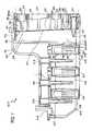
- FIG. 1is a perspective view of an instrument for a cassette for sample preparation in accordance with one embodiment of the invention
- FIG. 2is a perspective view of a magazine insertable into the instrument of FIG. 1 in accordance with one embodiment of the invention
- FIG. 3is a perspective view of a cassette for preparing samples in accordance with one embodiment of the invention.
- FIG. 4is a cross-sectional side view of the cassette for preparing samples of FIG. 3 in accordance with one embodiment of the invention
- FIG. 5is a perspective view of an instrument for a cassette for sample preparation in accordance with one embodiment of the invention.
- FIG. 6Ais a block diagram of the system of the instrument of FIG. 5 in accordance with one embodiment of the invention.
- FIG. 6Bis a top level digital block diagram of the system controller of the instrument of FIG. 5 in accordance with one embodiment of the invention.
- FIG. 6Cis a digital processing block diagram of the system controller of the instrument of FIG. 5 in accordance with one embodiment of the invention.
- FIG. 6Dis an Instrument Module (IM) block diagram of FIG. 5 in accordance with one embodiment of the invention.
- IMInstrument Module
- FIG. 7is a detailed perspective view of a parallel tray driving motor assembly module in accordance with one embodiment of the invention.
- FIG. 8is a detailed perspective view of the reagent release and pre-mix assembly module in accordance with one embodiment of the invention.
- FIG. 9is a detailed side view of the reagent release and pre-mix assembly module in accordance with one embodiment of the invention.
- FIG. 10is a detailed perspective view of a close-loop heater and temperature sensor assembly module in accordance with one embodiment of the invention.
- FIG. 11is a detailed side view of the close-loop heater and temperature sensor assembly module in accordance with one embodiment of the invention.
- FIG. 12is a detailed perspective view of a parallel wash buffer pumping assembly module in accordance with one embodiment of the invention.
- FIG. 13is a detailed side view of the parallel wash buffer pumping assembly module in accordance with one embodiment of the invention.
- FIG. 14is a detailed perspective view of a parallel magnetic particles transfer assembly module in accordance with one embodiment of the invention.
- FIG. 15is a detailed side view of the parallel magnetic particles transfer assembly module in accordance with one embodiment of the invention.
- FIG. 1illustrates an instrument 100 in accordance with one embodiment of the invention.
- the instrument 100is a parallel processing system.
- the illustrated instrument 100includes a display 104 and openings 108 .
- the openings 108are configured to receive magazines 120 .
- the magazines 120each contain a series of cassettes 124 .
- Each cassetteincludes a sample of cells to be prepared.
- a protocolmay be selected by a user at the display 104 for preparing the sample in the cassette 124 within the instrument 100 .
- the instrument 100then automatically prepares the sample within the instrument according to the selected protocol.
- the instrumentcan process four magazines 120 , each magazine 120 having twelve cassettes 124 , each cassette having a sample of cells therein at the same time according to the selected protocol. It will be appreciated, however, that fewer than forty-eight or greater than forty-eight samples can be processed at a time.
- FIG. 2illustrates a magazine 200 in further detail.
- the magazine 200is the magazine 120 of FIG. 1 .
- the magazine 200is a rack.
- cassettes 224e.g., cassettes 124 from FIG. 1 .
- FIG. 3illustrates a cassette 300 in further detail.
- the cassette 300is the cassettes 124 in FIG. 1 and/or cassettes 224 in FIG. 2 .
- the cassette 300can be used to prepare cell samples.
- FIG. 4is a detailed view of the cassette of FIG. 3 .
- the cassette 400includes a housing 412 , a mixing chamber 414 , first, second, third and fourth holding chambers 416 , 418 , 420 and 422 , first, second, third and fourth plungers 424 , 426 , 428 and 430 , first, second and third valves 432 , 434 and 436 , first and second washing chambers 438 and 440 , an elution chamber 442 , first, second, third and fourth pumps 444 , 446 , 448 and 450 , first and second lids 452 and 454 , first and second heating elements 456 and 458 and a magnetic 460 .
- Each of the chambers 414 , 416 , 418 , 420 , 422 , 438 , 440 and 442 , plungers 424 , 426 , 428 and 430 , valves 432 , 434 , 436 , pumps 444 , 446 , 448 and 450 , and heating elements 456 and 458are enclosed within the housing 412 .
- the lids 452 and 454are movably attached to the housing 412 .
- the magnet 460is removably positionable in the first valve 432 , second valve 434 and third valve 436 .
- the mixing chamber 414has a top surface 462 , a bottom surface 464 and opposing side surfaces 466 , 468 .
- the top surface 462 of the mixing chamber 414includes an opening 470 therein.
- the first lid 452is configured to provide access to the opening 470 in the top surface 460 of the mixing chamber 414 .
- the first lid 452 and the opening 470are coaxial.
- the first lid 452is shown being movably attached to the housing 412 , such that when the lid 452 is open or off, the opening 470 is accessible and if the lid 452 is closed or on, the opening 470 is not accessible.
- a thin film 474forms one wall of the mixing chamber 414 .
- the thin chamber 474is breakable, such that the mixing chamber 414 is accessible when the thin film 474 has been broken or ruptured.
- the first holding chamber 416 , second holding chamber 418 , third holding chamber 420 and fourth holding chamber 422are shown located next to the mixing chamber 414 and aligned vertically with one another.
- Each of the holding chambers 416 , 418 , 420 , 422has an opening 476 next to the thin film 474 of the mixing chamber 414 .
- the cassette 400further includes magnetic iron particles in the form of magnetic beads in the first holding chamber 416 .
- the cassette 400further includes a binding solution in the second holding chamber 418 .
- the cassette 400further includes a lysis solution in the third holding chamber 420 .
- the cassette 400further includes a proteinase K (PK) solution in the fourth holding chamber 422 .
- the magnetic iron particles (in the form of magnetic beads), lysis solution, binding solution, and proteinase K (PK)can also be provided in any chamber of the cassette 400 based on desired protocol.
- the first, second, third and fourth plungers 424 , 426 , 428 and 430are located in the first, second, third and fourth holding chambers 416 , 418 , 420 and 422 , respectively.
- Each of the plungers 416 , 418 , 420 , 422includes a base 478 , a shaft 480 and a piercing element 482 .
- the shaft 480extends from the base 478 .
- the piercing element 482is at the end of the shaft 480 opposing the base 478 and is pointed.
- the piercing element 482is configured to break or rupture the thin film 474 of the mixing chamber 414 .
- the first pump 444is a bellows pump having a pumping portion and a nozzle portion.
- the nozzle portion of the first pump 444is located inside the mixing chamber 414 .
- the pumping portion of the first pump 444is located outside the mixing chamber, such that the pumping portion is actuatable.
- a heating element 456is provided at the bottom surface 464 of the mixing chamber 414 for heating the contents of the mixing chamber 414 .
- the heating element 456may be a variable heating element.
- the opposing side surface 468 of the mixing chamber 414also includes an opening 484 .
- a first valve 432is provided between the opening 484 in the side 468 of the mixing chamber 414 and the first washing chamber 438 .
- the first valve 432has a first stationary piece 486 and a second moveable piece 488 , the second piece 488 being moveable relative to the first piece 486 .
- the first stationary piece 486includes a first opening 490 and a second opening 492 and has a surface 494 .
- the second piece 488has an opening 495 therein for receiving the magnet 460 .
- the second piece 488has a surface 496 with a cavity 498 therein.
- the magnet 460is shaped to correspond to the opening 495 in the second piece 488 .
- the magnet 460is moveable in the opening 495 of the second piece 488 , and is removable from the second piece 488 .
- the cassette 400includes a washing solution in the first washing chamber 438 .
- the second pump 446is also a bellows pump, and the nozzle portion of the second pump 446 is located in the first washing chamber 438 .
- the second valve 434is provided between the first washing chamber 438 and the second washing chamber 440 .
- the second valve 434is structurally and functionally the same as the first valve 432 , and also includes a first stationary piece 486 and a second moveable piece 488 .
- the first stationary piece 486includes a first opening 490 and a second opening 492 and has a surface 494 .
- the second moveable piecehas a surface 496 with a cavity 498 therein.
- the cassette 400includes a washing solution in the second washing chamber 440 .
- the third pump 448is also a bellows pump, and the nozzle portion of the third pump 448 is located in the second washing chamber 440 .
- the third valve 436is provided between the second washing chamber 440 and the elution chamber 442 .
- the third valve 436is structurally and functionally the same as the first valve 432 , and also includes a first stationary piece 486 and a second moveable piece 488 .
- the first stationary piece 486includes a first opening 490 and a second opening 492 and has a surface 494 .
- the second moveable piecehas a surface 496 with a cavity 498 therein.
- the cassette 400includes a washing solution in the elution chamber 442 .
- the fourth pump 450is also a bellows pump, and the nozzle portion of the fourth pump 450 is located in the elution chamber 442 .
- a heating element 458is provided at the bottom surface of the elution chamber 442 for heating the contents of the elution chamber 442 .
- the heating element 458may be a variable heating element.
- the elution chamber 442includes an opening 499 at its top surface for accessing the contents of the elution chamber 442 .
- the second lid 442is configured to provide access to the opening 499 in the top surface of the elution chamber 442 .
- the second lid 454is coaxial with the opening 499 .
- the second lid 454is shown being movably attached to the housing 412 , such that when the lid 454 is open or off, the opening 499 is accessible and if the lid 454 is closed or on, the opening 499 is not accessible.
- the first lid 452is removed to provide access to the opening 470 of the mixing chamber 414 .
- a sample of cellsis placed into the cassette 400 and, in particular, into the mixing chamber 414 .
- the cells in the sampleinclude nucleic acid.
- the PK solutionis then added to the sample.
- the PK solutionis added by moving the plunger 430 in the fourth holding chamber 422 .
- a forceis applied to the base 478 of the plunger 430 to move the plunger 430 .
- the piercing element 482 of the plunger 430advances toward the mixing chamber 414 , the piercing element 482 punctures and ruptures the thin film 474 .
- the break in the thin film 474provides access to the mixing chamber 414 .
- Continued motion of the plunger 430transfers the contents (e.g., PK solution) of the first holding chamber 422 into the mixing chamber 414 .
- the PK solutionis mixed with the sample by pumping the mixture with, for example, the first pump 444 .
- the PK solutionbreaks up/destroys the walls of the cells of the sample, creating bulk material and nucleic acid in the bulk material.
- the lysis solutionis then added to the sample in a manner similar to the PK solution.
- the lysis solutionis typically a salt or detergent.
- the lysis solutionis used to solulibize the bulk material.
- the lysis solutiontypically does not solulibize proteins.
- the heating element 456may be used to heat the lysis solution and sample. As described hereinabove, the temperature of the heating element 456 may be variable, and is selected to optimize the effectiveness of the lysis solution.
- the binding solutionis then added to the sample, PK solution and lysis buffer solution.
- the binding solutionis typically hydrophobic and increases salt in the solution.
- the binding solutioncauses the nucleic acid to be magnetically charged.
- the magnetic beadsare then added to the solution and pumped.
- the magnetic beadsbind to the magnetically charged nucleic acid.
- the magnetic beads, together with the nucleic acid,are bound to the first valve 432 .
- the removable positionable magnet 460is placed in the first valve 432 and slid to a position in the first valve 432 to attract the magnetic beads, which are bound to the nucleic acid, from the mixing chamber 414 to the first valve 432 .
- the magnetic beads, together with the nucleic acid,are then moved from the mixing chamber 414 and received in the first washing chamber 438 .
- the magnet 460is inserted into the opening 494 of the second piece 488 .
- the magnet 460is inserted to a position corresponding to the openings 490 and 492 of the first piece 486 .
- the magnet 460attracts the magnetic beads from the mixing chamber 414 through the opening 490 in the first piece 486 and into the cavity 498 in the second piece 488 .
- the second piece 488is rotated such that the magnetic beads are sealed in the cavity 498 of the second piece 488 , between surfaces of the second piece 488 and the first piece 486 .
- the second piece 488is rotated past the surface 494 of the first piece 486 , such that the cavity 498 is accessible in the opening 492 of the first piece 486 .
- the magnet 460is then removed from the opening 494 in the second piece 488 to release the magnetic beads from the cavity 498 in the second piece 488 .
- the magnetic beads and nucleic acidare then washed with the washing solution by pumping the solution with the second pump 446 .
- the magnetic beads, together with the nucleic acid,are then bound to the second valve 434 by inserting the magnet 460 into the second valve 434 .
- the magnetic beads, together with the nucleic acid,are then moved from the first washing chamber 438 to the second washing chamber 440 using the second valve 434 .
- the second valve 434transfers the magnetic beads and nucleic acid from the first washing chamber 438 to the second washing chamber 440 .
- the magnetic beads and nucleic acidare then washed with the washing solution a second time by pumping the solution with the third pump 448 .
- the magnetic beads, together with the nucleic acid,are then bound to the third valve 436 by positioning the magnet 460 in the third valve 436 .
- the magnetic beads and nucleic acidare then moved from the second washing chamber 440 to the elution chamber 442 .
- the magnetic beads and nucleic acidare transferred from the second washing chamber 440 to the elution chamber 442 .
- An elution buffer solutionis then mixed with the magnetic beads and nucleic acid by pumping the solution with the fourth pump 450 .
- the heating element 458may be used to heat the elution buffer, magnetic beads and nucleic acid.
- the temperaturemay be variable and may be selected to optimize release of the nucleic acid from the magnetic beads.
- the magnetic beads aloneare then bound again to the third valve 436 by positioning the magnet 460 in the third valve 436 .
- the magnetic beads aloneare then moved from the elution chamber 442 back into the second washing chamber 440 , leaving the nucleic acid in the elution chamber 442 .
- the magnetic beadsare transferred from the elution chamber 442 to the second washing chamber 440 .
- the prepared sample of nucleic acidmay be accessed from the opening 499 in the elution chamber 442 .
- the second lid 54is removed to provide access to the opening 499 in the elution chamber 42 .
- a pipette or a multi-channel pipettemay be used to place the sample in the cassette and/or access the sample or a plurality of samples in the cassette(s).
- the cassettemay vary from that illustrated and described above.
- sealsmay be provided in the cassette as need.
- the cassette 400has been described as having a mixing chamber 414 , two washing chambers 438 and 440 and an elution chamber 442 , it is envisioned that only one washing chamber or no washing chamber may alternatively be provided.
- valvesmay have a different arrangement than that described above.
- each valvemay include a positionable magnet, such that the magnet does not need to be removed.
- the magnet 460may be rotatable, and used to rotate the second piece of the valves.
- the magnetmay only slide inside of each of the valves, and the second piece is rotated independent of the magnet.
- a cassette 400that does not use valves as described herein may be used to transfer the magnetic particles from the mixing chamber to the elution chamber.
- a slideable magnetmay be provided to transfer the magnetic particles from one chamber to the next.
- the housing 412may be transparent, such that the procedure can be viewed.
- the thin film 474is a lamination.
- the lids 452 and 454may be screw-top lids.
- the lids 452 , 454include a hydrophobic membrane, which allows gasses to vent through the lid, but does not allow the liquids to escape the cassette 400 .
- pump 450is insertable into opening 499 .
- pump 450can also be used as a pipette to remove the sample from the cassette 400 .
- the mixing chamber 414may be provided without a puncturable thin film 474 .
- the plungers 424 , 426 , 428 and 430would not need a piercing element 482 . Instead, the plungers 424 , 426 , 428 and 430 would have a sealing element to prevent leakage of the contents of the holding chamber 416 , 418 , 420 and 422 , associated with each plunger 424 , 426 , 428 and 430 , respectively, until the plunger was moved.
- a total of about 200 ⁇ L sampleis placed into the cassette.
- the sampleis mixed with a total of about 50 ⁇ L of the PK solution by pumping the mixture of the sample and PK solution for about one minute.
- a total of about 200 ⁇ L of the lysis solutionis added to the sample and PK solution, and the solutions are pumped for about one minute to mix the solutions.
- the mixtureis then heated at about 60° C. for about ten minutes, and the mixture is allowed to cool for about 5 minutes.
- the mixtureis further pumped while it cools.
- a total of about 500 ⁇ L of binding solutionis added to the mixture.
- the solutionsare pumped for about one minute.
- the magnetic beadsare added to the solution and pumped for about two minutes. The magnetic beads are transferred and washed as described above.
- a total of about 700 ⁇ L of washing solutionis provided in each of the washing chambers.
- a total of about 200 ⁇ L of elution solutionis provided in the elution chamber.
- the magnetic beadsare mixed with the elution solution by pumping the mixture for about one minute.
- the mixtureis then heated at about 90° C. for about two minutes. The process continues as previously described. It will be appreciated that the amounts, times and temperatures described above may vary from that described above.
- cassette 400has been described as using a PK solution, lysis solution, binding solution and magnetic beads to release the nucleic acid and magnetic beads, it is envisioned that it may be possible to practice the invention without using each of the above solutions.
- the solutionwas described as using a PK solution to break up the cells, it is envisioned that any enzyme which causes cells to break up to release nucleic acid may be used with the invention.
- additional solutionsmay be provided, as needed, to prepare the sample.
- the cassette 400may be modified to have fewer holding chambers if fewer solutions are used or additional holding chambers if additional solutions are used.
- FIG. 5illustrates another embodiment of an instrument 500 in accordance with one embodiment of the invention. It will be appreciated that the magazine and cassettes described herein with reference to FIGS. 2-4 can be used with the instrument 500 .
- the instrument 500allows for parallel processing of one or more samples within a closed, sterile environment.
- Instrument 500includes an enclosure 502 , an instrument handle 504 , stackable holders 506 , an instrument module 508 , a computer module 510 , a touch panel display 512 , an instrument run time indicator 514 , first and second automatic eject/load trays 516 , 518 , first and second tray doors 520 , 522 , and first and second tray safety guards 524 , 526 .
- the instrument module 508is within the enclosure 502 and is configured to perform the protocol selected to prepare the sample.
- the protocolis selected by the user using the touch screen display 512 .
- the display 512is a touch screen display.
- the display 512may be, for example, a 7′′ to 12′′ touch screen LCD display.
- the user's selection at the display 512is communicated to the computer module 510 which communicates with the instrument module 508 via a controller area network bus (CAN-BUS) to coordinate processing within the instrument 500 .
- CAN-BUScontroller area network bus
- the stackable holders 506enable multiple instruments 500 to be stacked on top of one another such that even more samples can be processed at any given time.
- one computer module 510 and display 512may be provided to control processing within multiple stacked instruments.
- the first and second automatic eject/load trays 516 , 518are configured to receive a magazine (e.g., magazine 200 ) having one or more cassettes therein (e.g., cassette 400 ).
- the magazinesare automatically loaded into the instrument 500 by the automatic eject/load trays 516 , 518 .
- the first and second cassette doors 520 , 522are closed and engage with the first and second tray safety guards 524 , 526 to secure the magazine and cassettes within the enclosure 502 of the instrument 500 for preparation of the sample. It will be appreciated that in alternative embodiments the trays 516 , 518 and/or doors 520 , 522 may be manually opened and closed.
- the instrument run time indicator 514is an LED or other exemplary light source.
- the instrument run time indicator 514is illuminated to indicate to a user about the instrument ID and run status.
- the computer module 510provides an indication to the instrument run time indicator 514 to illuminate the communication status between the controller and the instrument.
- FIG. 6Ais a block diagram of the system components 600 of the instrument 500 .
- the system components 600include, a main computer 602 , a display panel 604 , a sub-system computer 606 , an instrument interface parallel controller 608 , an instrument real time microcontroller unit (MCU) 610 , a cooling system 612 , a tray motor driving system 614 , a heater control and detection system 616 , a magnetic particle transfer system 618 , a reagent release system 620 , a reagent pre-mix pumping system 622 and a wash buffer pumping system 624 .
- MCUinstrument real time microcontroller unit
- each of the cooling system 612 , tray motor driving system 614 , heater control and detection system 616 , magnetic particle transfer system 618 , reagent release system 620 , reagent pre-mix pumping system 622 and wash buffer pumping system 624communicate with the instrument interface parallel controller 608 .
- the instrument interface parallel controlleris configured to control the subsystems 612 - 624 such that up to twenty-four samples can be prepared at a given time. It will be appreciated, however, that the instrument can be configured to prepare fewer than or greater than twenty-four samples. It will be appreciated that the system components 600 communicate with one another to enable parallel processing of the sample(s) within the instrument 500 .
- the instrument interface parallel controller 608also communicates with the instrument real time MCU 610 , the cooling system 612 and the sub-system computer 606 .
- the sub-system computer 606communicates with the main computer 602 .
- the main computer 602communicates with the touch screen display panel 604 .
- the main computer 602 , sub-system computer 606 , and/or the instrument interface parallel controller 608are a digital processing system.
- the digital processing systemmay include a microprocessor, an ASIC (application specific integrated circuit), FPGA (field-programmable gate array), DSP (digital signal processor), or the like.
- the display panel 604is a 7′′ high definition (HD) liquid crystal display (LCD) with a touch panel.
- the display panel 604is on an external surface of the instrument 500 such that the user can interact with the display panel 604 .
- the main computer 602may be a stand alone system that includes the computer module 510 and display 512 .
- the sub-system computer 606 and instrument interface parallel controller 608are within the enclosure 502 of the instrument 500 .
- the usercan select a protocol for processing the sample(s) with the display panel 604 .
- the display panel 604communicates the user selection to the main computer 602 , sub-system computer 606 and/or parallel controller 608 to perform the protocol using the tray motor driving system 614 , heater control and detection system 616 , magnetic particle transfer system 618 , reagent release system 620 , reagent pre-mix pumping system 622 and wash buffer pumping system 624 .
- the tray motor driving system 614is configured to control the automatic load/eject trays 516 , 518 (from FIG. 5 ) and cassette doors 520 , 522 to automatically load the cassettes (e.g., cassette 400 ) for processing and eject the cassettes when processing of the sample is completed.
- the cassettese.g., cassette 400
- the heater control and detection system 616is configured to control and detect the temperature of the cassette or cassettes.
- the heater control and detection systemmay also control the heaters within the cassette to perform a close loop temperature ramping and detection.
- the heater control and detection system 614may include heaters that are configured as a programmable temperature controller to heat the contents of the cassette to a predefined temperature, as needed, according to the selected protocol.
- the magnetic particle transfer system 618is configured to transfer magnetic particles within the cassette (e.g., cassette 400 ) according to the selected protocol. In one embodiment, the magnetic particle transfer system 618 manipulates the valves 432 , 434 , 436 to transfer the magnetic particles as described above with reference to FIG. 4 .
- the reagent release system 620is configured to release the reagents within the cassette.
- the reagent release systemis configured to release the PK solution, lysis solution, binding solution and magnetic beads from their respective holding chambers 416 , 418 , 420 and 422 and into the mixing chamber 414 , as described above with reference to FIG. 4 .
- the reagent pre-mix pumping system 622is configured to mix the reagents in the mixing chamber 414 as described above with reference to FIG. 4 .
- the wash buffer pumping system 624is configured to pump the washing solution in the cassette, as described above with reference to FIG. 4 .
- the wash buffer pumping system 624may be configured to actuate the pumps 446 , 448 , 450 in the wash chambers 438 , 440 and elution chamber 442 .
- FIG. 6Billustrates a block diagram of a digital system 630 in accordance with one embodiment of the invention.
- the illustrated digital system 630includes a system controller module (SCM) 632 , a first instrument module (IM) 1 634 , a second instrument module (IM) 2 636 and a nth instrument module (IM) N 638 .
- the SCM 632controls each of the IM 1 634 , IM 2 636 and up to an nth IM N 638 . It will be appreciated that the SCM 632 may control any number of IMs as represented by N. Thus, N may be any number from 0 up to 100 or even more.
- FIG. 6Cis a block diagram illustrating the system controller module 632 of FIG. 6B in further detail.
- the system controller module 632includes a main processor unit 640 , a Complex Programmable Logic Device (CPLD) 642 , a Liquid Crystal Display (LCD) 644 , a Synchronous Dynamic Random Access Memory (SDRAM) 646 , a NOR flash 648 , a NAND flash 650 , a Storage Device (SD) card 652 , a Universal Asynchronous Receiver-Transmitter (UART) 654 , a CANBUS 656 , a Universal Serial Bus (USB) 658 , an Ethernet 660 and a system bus 662 to couple each of the components 640 - 662 .
- CPLDComplex Programmable Logic Device
- LCDLiquid Crystal Display
- SDRAMSynchronous Dynamic Random Access Memory
- NOR flash 648NOR flash
- NAND flash 650a NAND flash 650
- SDStorage Device
- UART
- the bus 662 or other internal communication meansis for communicating information, and the main processor unit 640 is coupled to the bus 662 for processing information.
- SDRAM 646 , NOR flash 648 , NAND flash 650 , and SD card 652are for storing information and instructions to be executed by the main processor unit 640 , for storing temporary variables or other intermediate information during execution of instructions by main processor unit 640 , for storing static information and instructions for main processor unit 640 , and the like.
- the systemmay further be coupled to a display device, such as a cathode ray tube (CRT) or a liquid crystal display (LCD) 644 , coupled to bus 662 through bus 662 for displaying information to a computer user.
- a display devicesuch as a cathode ray tube (CRT) or a liquid crystal display (LCD) 644
- An alphanumeric input device 675may also be coupled to bus 662 through bus 662 for communicating information and command selections to the main processor unit 640 .
- An additional user input deviceis cursor control device, such as a mouse, a trackball, stylus, or cursor direction keys coupled to bus 662 through bus 662 for communicating direction information and command selections to main processor unit 640 , and for controlling cursor movement on display device 644 .
- Another devicewhich may optionally be coupled to computer system, is a communication device, such as UART 654 , CANBUS 656 , USB 658 , and Ethernet 660 , for accessing other nodes of a distributed system via a network.
- the communication devicemay include any of a number of commercially available networking peripheral devices such as those used for coupling to an Ethernet, token ring, Internet, control area network (CAN), wide area network (WAN), and wireless network (WIFI).
- the communication devicemay further be a null-modem connection via UART, or any other mechanism that provides connectivity between the computer system and the outside world, or any other mechanism that provides connectivity between the controller computer system and instrument modules. Note that any or all of the components of this system illustrated in FIG. 6C and associated hardware may be used in various embodiments of the present invention.
- control logic or software implementing the present inventioncan be stored in SDRAM 646 , NOR Flash 648 , NAND flash 650 , SD card 652 , FPGA, CPLD or other storage medium locally or remotely accessible to main processor unit 640 .
- main processor unit 640can be implemented as software stored in memory and executed by main processor unit 640 .
- This control logic or softwaremay also be resident on an article of manufacture comprising a computer readable medium having computer readable program code embodied therein and being readable by the storage device and for causing the main processor unit 640 to operate in accordance with the methods and teachings herein.
- the present inventionmay also be embodied in a handheld or portable device containing a subset of the computer hardware components described above.
- the handheld devicemay be configured to contain only the bus 662 , the main processor unit 640 , and SDRAM 646 .
- the handheld devicemay also be configured to include a set of buttons or input signaling components with which a user may select from a set of available options.
- the handheld devicemay also be configured to include an output apparatus such as a liquid crystal display (LCD) or display element matrix for displaying information to a user of the handheld device. Conventional methods may be used to implement such a handheld device.
- LCDliquid crystal display
- Conventional methodsmay be used to implement such a handheld device.
- the implementation of the present invention for such a devicewould be apparent to one of ordinary skill in the art given the disclosure of the present invention as provided herein.
- the present inventionmay also be embodied in a special purpose appliance including a subset of the computer hardware components described above.
- the appliancemay include a main processor unit 640 , SDRAM 646 and bus 662 , and only rudimentary communications mechanisms, such as a small touch-screen that permits the user to communicate in a basic manner with the device.
- main processor unit 640the more special-purpose the device is, the fewer of the elements need to be presented for the device to function.
- communications with the usermay be through a touch-based screen, USB devices, or similar mechanism.
- a machine-readable mediumincludes any mechanism for storing or transmitting information in a form readable by a machine (e.g. a computer).
- a machine readable mediumincludes read-only memory (ROM), random access memory (RAM), magnetic disk storage media, optical storage media, flash memory devices, electrical, optical, acoustical or other forms of propagated signals (e.g. carrier waves, infrared signals, digital signals, etc.).
- FIG. 6Dis a block diagram illustrating the instrument modules 634 , 636 , 638 of FIG. 6B in further detail.
- the instrument modules 634 , 636 , 638include a databus 664 , a stepper motor controller 666 , initial data 667 , a main stepper controller 668 , an ADC reader 670 , an input data device 672 and an output data device 674 .
- the stepper motor controller 666 , initial data 666 , main stepper controller 668 , Analog-to-Digital Converter (ADC) reader 670 , input data device 672 and output data device 674are each coupled to the databus 664 .
- ADCAnalog-to-Digital Converter
- the instrument moduleis shown for the tray motor driving module of FIG. 6A . It will be appreciated that the instrument modules for the other modules of FIG. 6A will have similar components as the illustrated instrument module; however, the inputs and outputs coupled with the instrument modules may vary.
- the illustrated databus 664is also coupled with a MCU 676 .
- the stepper motor controller 666is also coupled with the motor sensor 678 , motor driver 2 680 and motor driver 3 682 .
- the main stepper controller 668is also coupled with the motor driver 1 684 and protect sensor 686 .
- the ADC reader 670is also coupled with the ADC 688 .
- the input data device 672is also coupled with the door sensor 690 , main motor home sensor 692 , and cassette sensor 694 .
- the output data device 674is also coupled with the fan 696 and the heater 698 .
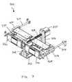
- FIG. 7illustrates a tray driving motor assembly module 700 .
- the tray driving motor assembly module 700is part of the tray motor driving system 614 of FIG. 6 .
- the tray driving motor assembly module 700is within the instrument module 508 of the instrument 500 as described above with reference to FIG. 5 .
- the tray driving motor assembly module 700includes an alignment plate 702 , a first drive shaft retention block 704 , a second drive shaft retention block 706 , a load driving shaft 708 , a main driving motor 710 , a first parallel shaft 712 , a second parallel shaft 714 , a first parallel linear drive 716 , a second parallel linear drive 718 , a first load resistance tray 720 , a first door 722 , a second load resistance tray 724 and a second door 726 .
- the main drive motor 710is coupled with the load driving shaft 708 via the retention blocks 704 , 706 to automatically load and eject the rack trays 720 , 724 into the instrument.
- the trays 720 , 724also slide along the parallel shafts 712 , 714 with the main drive motor 710 and the drives 716 , 718 to load and eject the racks 720 , 724 .
- the motor 710 and/or drivers 712 , 714can also be used to open and close the doors 722 , 726 .
- FIG. 8illustrates a reagent release and pre-mix assembly module 800 .
- the reagent release and pre-mix assembly module 800is part of the reagent release system 620 and reagent pre-mix pumping system 622 .
- the reagent release and pre-mix assembly module 800is within the instrument module 508 of the instrument 500 as described above with reference to FIG. 5 .
- the reagent release and pre-mix assembly module 800includes a precision vertical engagement driving motor 802 , a vertical drive shaft 803 , a stand 804 , a first plunger assembly 806 , a second plunger assembly 808 , a first parallel horizontal pump activation motor 810 , a second parallel horizontal pump activation motor 812 , first, second, third and fourth horizontal parallel linear driving shafts and bearings 814 , 816 , 818 and 820 , and first, second, third and fourth vertical parallel linear bearings 822 , 824 , 826 and 828 .
- each of the plunger assemblies 806 , 808includes twelve plungers (e.g., one plunger for each cassette in the magazine). It will be appreciated that the plunger assemblies 806 , 808 may have fewer than or greater than twelve plungers.
- FIG. 9is a side view of reagent release and pre-mix assembly module 800 of FIG. 8 . As shown in FIG. 9 , the reagent release and pre-mix assembly module 800 of FIG. 8 also includes a vertical position sensor 830 .
- the stand 804is coupled with the vertical drive shaft 803 , which is coupled with the vertical engagement driving motor 802 to vertically position the stand 804 .
- the plunger assemblies 806 , 808are coupled with the stand 804 and are, thus, also vertically positioned with the stand 804 when the motor 802 is actuated.
- the vertical position sensor 830is coupled with the stand 804 to sense the position of the stand 804 and/or plunger assemblies 806 , 808 .
- the vertical position sensor 830communicates with a controller to control actuation of the motor 802 .
- the plunger assemblies 806 , 808are also actuatable horizontally via the horizontal drive shafts and bearings 814 - 820 , which are coupled with the horizontal motors 810 , 812 .
- the plunger assemblies 806 , 808are actuated in a vertical direction to align the plungers 806 , 808 with one of the holding chambers of the cassette 400 .
- the plunger assemblies 806 , 808are also actuated horizontally to force the contents of the holding chambers into the mixing chamber of the cassette 400 .
- the plunger assemblies 806 , 808are then repositioned vertically to align with another holding chamber and are similarly actuated horizontally to force the contents of the holding chamber into the mixing chamber according to the selected protocol.
- the plunger assemblies 806 , 808are also actuated to actuate the pump 444 that mixes the contents of the mixing chamber of the cassette 400 .
- FIGS. 10 and 11illustrate a heater and temperature sensor assembly module 1000 .
- the heater and temperature sensor assembly module 1000is part of the heater control and detection system 616 .
- the heater and temperature sensor assembly module 1000is within the instrument module 508 of the instrument 500 as described above with reference to FIG. 5 .
- the heater and temperature sensor assembly module 1000includes a precision vertical engagement driving motor 1002 , a vertical position sensor 1004 , a rack 1006 , a first vertical linear bearing 1008 , a second vertical linear bearing 1010 , a plurality of heater and thermal sensor connectors 1012 and a plurality of individually controlled parallel heaters and thermal sensors 1014 .
- the plurality of individually controlled parallel heaters and thermal sensors 1014are self-aligned with the plurality of heater and thermal sensor connectors 1012 .
- the heater and temperature sensor assembly module 1000includes twenty-four heater and thermal sensor connectors 1012 and twenty-four individually controlled parallel heaters and thermal sensors 1014 . It will be appreciated that the heater and temperature sensor assembly module 1000 may include fewer than or greater than twenty-four connectors 1012 and/or heaters/sensors 1014 .
- the vertical linear bearings 1008 , 1010are coupled with the vertical engagement driving motor 1002 to vertically position the rack 1006 .
- the plurality of heater and thermal sensor connectors 1012 and plurality of individually controlled parallel heaters and thermal sensors 1014are coupled with respective sides of the rack 1006 .
- the plurality of heater and thermal sensor connectors 1012 and plurality of individually controlled parallel heaters and thermal sensors 1014are vertically positionable by vertically positioning the rack 1006 .
- the vertical precision position sensor 1004coupled with the rack 1006 , can be used to accurately position the plurality of heater and thermal sensor connectors 1012 and plurality of individually controlled parallel heaters and thermal sensors 1014 .
- FIGS. 12 and 13illustrate a wash buffer pumping assembly module 1200 .
- the wash buffer pumping assembly module 1200is part of the wash buffer pumping system 624 .
- the wash buffer pumping assembly module 1200is within the instrument module 508 of the instrument 500 as described above with reference to FIG. 5 .
- the wash buffer pumping assembly module 1200includes a rack 1202 , a plurality of parallel vertical pump engagement plungers 1204 , a first parallel vertical pump activation motor 1206 , a second parallel vertical pump activation motor 1208 , and first, second, third and fourth vertical parallel linear driving shafts and bearings 1210 , 1212 , 1214 and 1216 . As shown in FIG. 13 , the wash buffer pumping assembly module 1200 also includes first and second vertical precision position sensors 1218 and 1220 .
- the first vertical pump activation motor 1206is coupled with the first and second vertical parallel linear driving shafts and bearings 1210 , 1212 to vertically position a first set of parallel vertical pump engagement plungers 1204 a .
- the second vertical pump activation motor 1206is coupled with the third and fourth vertical parallel linear driving shafts and bearings 1214 , 1216 to vertically position a second set of parallel vertical pump engagement plungers 1204 b.
- the plungers from the vertical pump engagement plungers 1204engage with the cassette (e.g., cassette 400 ) to actuate the pumps 446 , 448 , 450 in the wash chambers 438 , 440 and elution chamber 442 according to the selected protocol.
- the cassettee.g., cassette 400
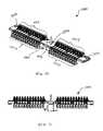
- FIGS. 14 and 15illustrate a magnetic particles transfer assembly module 1400 .
- the magnetic particles transfer assembly module 1400is part of the magnetic particle transfer system 618 .
- the magnetic particles transfer assembly module 1400is within the instrument module 508 of the instrument 500 as described above with reference to FIG. 5 .
- the magnetic particles transfer assembly module 1400includes a rack 1402 , a precision vertical engagement driving motor 1402 , a first particle transfer linear motor 1404 , a second particle transfer linear motor 1406 , first, second, third and fourth gear rack retention roller bearings 1408 , 1410 , 1412 and 1416 , first and second vertical linear bearings 1418 and 1420 , first and second driving gear racks 1422 , 1423 , a plurality of parallel precision gears 1424 and a plurality of parallel magnets and valve key shafts 1426 . As shown in FIG.
- the magnetic particles transfer assembly module 1400also includes first and second linear driving shafts 1428 and 1430 , first, second, third and fourth shaft and gear rack link blocks 1432 , 1434 , 1436 and 1438 , first, second, third and fourth horizontal precision position sensors 1440 , 1442 , 1444 and 1446 , and a vertical precision position sensor 1448 .
- the magnetic particles transfer assembly module 1400includes twenty-four parallel precision gears 1424 and twenty-four parallel magnets and valve key shafts 1426 . It will be appreciated that the magnetic particles transfer assembly module 1400 may have fewer than or greater than twenty-four gears 1424 and magnets and key shafts 1426 .
- the precision vertical engagement driving motor 1402is coupled with vertical bearings 1418 , 1420 and the rack 1403 to vertically position the rack 1403 .
- the plurality of parallel magnets and valve key shafts 1426are positioned on the rack 1403 and are vertically positioned when the rack 1403 is vertically positioned.
- the vertical precision position sensor 1448is coupled with the rack 1403 and motor 1402 to accurately position the plurality of parallel magnets and valve key shafts 1426 in the cassette (e.g., cassette 400 ).
- the particle transfer linear motors 1404 , 1405are positioned on either end of the rack 1403 and are coupled with the linear driving shafts 1428 , 1430 , shaft and gear rack link blocks 1432 - 1438 , driving gear racks 1422 , gears 1424 , to horizontally position and rotate the plurality of parallel magnets and valve key shafts 1426 via the gears 1424 to transfer magnetic particles as described above with reference to FIG. 4 . It will be appreciated that the gears 1424 and magnets and shafts 1426 can be repositioned to transfer the particles with each valve of the cassette.
Landscapes
- Chemical & Material Sciences (AREA)
- Health & Medical Sciences (AREA)
- Life Sciences & Earth Sciences (AREA)
- Analytical Chemistry (AREA)
- Engineering & Computer Science (AREA)
- General Health & Medical Sciences (AREA)
- Physics & Mathematics (AREA)
- Biochemistry (AREA)
- Immunology (AREA)
- Organic Chemistry (AREA)
- Genetics & Genomics (AREA)
- Wood Science & Technology (AREA)
- Zoology (AREA)
- Biomedical Technology (AREA)
- General Physics & Mathematics (AREA)
- Pathology (AREA)
- Biotechnology (AREA)
- Bioinformatics & Cheminformatics (AREA)
- General Engineering & Computer Science (AREA)
- Chemical Kinetics & Catalysis (AREA)
- Molecular Biology (AREA)
- Biophysics (AREA)
- Microbiology (AREA)
- Proteomics, Peptides & Aminoacids (AREA)
- Clinical Laboratory Science (AREA)
- Crystallography & Structural Chemistry (AREA)
- Plant Pathology (AREA)
- Hematology (AREA)
- Medicinal Chemistry (AREA)
- Automatic Analysis And Handling Materials Therefor (AREA)
Abstract
Description
Claims (18)
Priority Applications (9)
| Application Number | Priority Date | Filing Date | Title |
|---|---|---|---|
| US13/044,109US8029746B2 (en) | 2006-12-27 | 2011-03-09 | Instrument for cassette for sample preparation |
| US13/234,770US8168443B2 (en) | 2006-12-27 | 2011-09-16 | Instrument for cassette for sample preparation |
| US13/459,469US8900877B2 (en) | 2006-12-27 | 2012-04-30 | Instrument for cassette for sample preparation |
| US14/525,976US9273344B2 (en) | 2006-12-27 | 2014-10-28 | Instrument for cassette for sample preparation |
| US15/006,494US9434939B2 (en) | 2006-12-27 | 2016-01-26 | Instrument for cassette for sample preparation |
| US15/232,980US9745615B2 (en) | 2006-12-27 | 2016-08-10 | Instrument for cassette for sample preparation |
| US15/659,221US9856517B2 (en) | 2006-12-27 | 2017-07-25 | Instrument for cassette for sample preparation |
| US15/838,812US10047391B2 (en) | 2006-12-27 | 2017-12-12 | Instrument for cassette for sample preparation |
| US16/058,076US10214767B2 (en) | 2006-12-27 | 2018-08-08 | Instrument for cassette for sample preparation |
Applications Claiming Priority (4)
| Application Number | Priority Date | Filing Date | Title |
|---|---|---|---|
| US88215006P | 2006-12-27 | 2006-12-27 | |
| US12/005,860US7754148B2 (en) | 2006-12-27 | 2007-12-27 | Instrument for cassette for sample preparation |
| US12/821,446US7910062B2 (en) | 2006-12-27 | 2010-06-23 | Instrument for cassette for sample preparation |
| US13/044,109US8029746B2 (en) | 2006-12-27 | 2011-03-09 | Instrument for cassette for sample preparation |
Related Parent Applications (1)
| Application Number | Title | Priority Date | Filing Date |
|---|---|---|---|
| US12/821,446ContinuationUS7910062B2 (en) | 2005-10-19 | 2010-06-23 | Instrument for cassette for sample preparation |
Related Child Applications (1)
| Application Number | Title | Priority Date | Filing Date |
|---|---|---|---|
| US13/234,770ContinuationUS8168443B2 (en) | 2006-12-27 | 2011-09-16 | Instrument for cassette for sample preparation |
Publications (2)
| Publication Number | Publication Date |
|---|---|
| US20110158849A1 US20110158849A1 (en) | 2011-06-30 |
| US8029746B2true US8029746B2 (en) | 2011-10-04 |
Family
ID=39584250
Family Applications (11)
| Application Number | Title | Priority Date | Filing Date |
|---|---|---|---|
| US12/005,860Active2028-06-28US7754148B2 (en) | 2005-10-19 | 2007-12-27 | Instrument for cassette for sample preparation |
| US12/821,446ActiveUS7910062B2 (en) | 2005-10-19 | 2010-06-23 | Instrument for cassette for sample preparation |
| US13/044,109ActiveUS8029746B2 (en) | 2006-12-27 | 2011-03-09 | Instrument for cassette for sample preparation |
| US13/234,770Expired - Fee RelatedUS8168443B2 (en) | 2006-12-27 | 2011-09-16 | Instrument for cassette for sample preparation |
| US13/459,469ActiveUS8900877B2 (en) | 2006-12-27 | 2012-04-30 | Instrument for cassette for sample preparation |
| US14/525,976Expired - Fee RelatedUS9273344B2 (en) | 2006-12-27 | 2014-10-28 | Instrument for cassette for sample preparation |
| US15/006,494Expired - Fee RelatedUS9434939B2 (en) | 2006-12-27 | 2016-01-26 | Instrument for cassette for sample preparation |
| US15/232,980ActiveUS9745615B2 (en) | 2006-12-27 | 2016-08-10 | Instrument for cassette for sample preparation |
| US15/659,221ActiveUS9856517B2 (en) | 2006-12-27 | 2017-07-25 | Instrument for cassette for sample preparation |
| US15/838,812ActiveUS10047391B2 (en) | 2006-12-27 | 2017-12-12 | Instrument for cassette for sample preparation |
| US16/058,076ActiveUS10214767B2 (en) | 2006-12-27 | 2018-08-08 | Instrument for cassette for sample preparation |
Family Applications Before (2)
| Application Number | Title | Priority Date | Filing Date |
|---|---|---|---|
| US12/005,860Active2028-06-28US7754148B2 (en) | 2005-10-19 | 2007-12-27 | Instrument for cassette for sample preparation |
| US12/821,446ActiveUS7910062B2 (en) | 2005-10-19 | 2010-06-23 | Instrument for cassette for sample preparation |
Family Applications After (8)
| Application Number | Title | Priority Date | Filing Date |
|---|---|---|---|
| US13/234,770Expired - Fee RelatedUS8168443B2 (en) | 2006-12-27 | 2011-09-16 | Instrument for cassette for sample preparation |
| US13/459,469ActiveUS8900877B2 (en) | 2006-12-27 | 2012-04-30 | Instrument for cassette for sample preparation |
| US14/525,976Expired - Fee RelatedUS9273344B2 (en) | 2006-12-27 | 2014-10-28 | Instrument for cassette for sample preparation |
| US15/006,494Expired - Fee RelatedUS9434939B2 (en) | 2006-12-27 | 2016-01-26 | Instrument for cassette for sample preparation |
| US15/232,980ActiveUS9745615B2 (en) | 2006-12-27 | 2016-08-10 | Instrument for cassette for sample preparation |
| US15/659,221ActiveUS9856517B2 (en) | 2006-12-27 | 2017-07-25 | Instrument for cassette for sample preparation |
| US15/838,812ActiveUS10047391B2 (en) | 2006-12-27 | 2017-12-12 | Instrument for cassette for sample preparation |
| US16/058,076ActiveUS10214767B2 (en) | 2006-12-27 | 2018-08-08 | Instrument for cassette for sample preparation |
Country Status (1)
| Country | Link |
|---|---|
| US (11) | US7754148B2 (en) |
Cited By (15)
| Publication number | Priority date | Publication date | Assignee | Title |
|---|---|---|---|---|
| US9513303B2 (en) | 2013-03-15 | 2016-12-06 | Abbott Laboratories | Light-blocking system for a diagnostic analyzer |
| US9539577B2 (en) | 2005-10-19 | 2017-01-10 | Luminex Corporation | Apparatus and methods for integrated sample preparation, reaction and detection |
| US9624531B2 (en) | 2005-10-19 | 2017-04-18 | Luminex Corporation | Cassette for sample preparation |
| US9632103B2 (en) | 2013-03-15 | 2017-04-25 | Abbott Laboraties | Linear track diagnostic analyzer |
| US9714420B2 (en) | 2011-03-07 | 2017-07-25 | Accelerate Diagnostics, Inc. | Rapid cell purification systems |
| US9841422B2 (en) | 2003-07-12 | 2017-12-12 | Accelerate Diagnostics, Inc. | Sensitive and rapid determination of antimicrobial susceptibility |
| US9993820B2 (en) | 2013-03-15 | 2018-06-12 | Abbott Laboratories | Automated reagent manager of a diagnostic analyzer system |
| US10023895B2 (en) | 2015-03-30 | 2018-07-17 | Accelerate Diagnostics, Inc. | Instrument and system for rapid microogranism identification and antimicrobial agent susceptibility testing |
| US10022720B2 (en) | 2015-06-12 | 2018-07-17 | Cytochip Inc. | Fluidic units and cartridges for multi-analyte analysis |
| US10077999B2 (en) | 2015-07-14 | 2018-09-18 | Cytochip Inc. | Volume sensing in fluidic cartridge |
| US10254204B2 (en) | 2011-03-07 | 2019-04-09 | Accelerate Diagnostics, Inc. | Membrane-assisted purification |
| US10253355B2 (en) | 2015-03-30 | 2019-04-09 | Accelerate Diagnostics, Inc. | Instrument and system for rapid microorganism identification and antimicrobial agent susceptibility testing |
| US10634602B2 (en) | 2015-06-12 | 2020-04-28 | Cytochip Inc. | Fluidic cartridge for cytometry and additional analysis |
| US11491487B2 (en) | 2017-10-23 | 2022-11-08 | Cytochip Inc. | Devices and methods for measuring analytes and target particles |
| US11603550B2 (en) | 2013-03-15 | 2023-03-14 | Accelerate Diagnostics, Inc. | Rapid determination of microbial growth and antimicrobial susceptibility |
Families Citing this family (71)
| Publication number | Priority date | Publication date | Assignee | Title |
|---|---|---|---|---|
| US7754148B2 (en) | 2006-12-27 | 2010-07-13 | Progentech Limited | Instrument for cassette for sample preparation |
| US9057568B2 (en)* | 2008-12-16 | 2015-06-16 | California Institute Of Technology | Temperature control devices and methods |
| US9700889B2 (en) | 2009-11-23 | 2017-07-11 | Cyvek, Inc. | Methods and systems for manufacture of microarray assay systems, conducting microfluidic assays, and monitoring and scanning to obtain microfluidic assay results |
| US9855735B2 (en) | 2009-11-23 | 2018-01-02 | Cyvek, Inc. | Portable microfluidic assay devices and methods of manufacture and use |
| US9759718B2 (en) | 2009-11-23 | 2017-09-12 | Cyvek, Inc. | PDMS membrane-confined nucleic acid and antibody/antigen-functionalized microlength tube capture elements, and systems employing them, and methods of their use |
| US10022696B2 (en) | 2009-11-23 | 2018-07-17 | Cyvek, Inc. | Microfluidic assay systems employing micro-particles and methods of manufacture |
| US9500645B2 (en)* | 2009-11-23 | 2016-11-22 | Cyvek, Inc. | Micro-tube particles for microfluidic assays and methods of manufacture |
| US10065403B2 (en) | 2009-11-23 | 2018-09-04 | Cyvek, Inc. | Microfluidic assay assemblies and methods of manufacture |
| WO2013134739A1 (en) | 2012-03-08 | 2013-09-12 | Cyvek, Inc. | Microfluidic assay operating system and methods of use |
| US8980550B2 (en) | 2009-12-15 | 2015-03-17 | California Institute Of Technology | Methods for measuring samples using consumer electronic devices and systems |
| CN103675303B (en)* | 2010-07-23 | 2016-02-03 | 贝克曼考尔特公司 | Sensing system |
| US9233369B2 (en) | 2010-12-23 | 2016-01-12 | California Institute Of Technology | Fluidic devices and fabrication methods for microfluidics |
| US8968585B2 (en) | 2010-12-23 | 2015-03-03 | California Institute Of Technology | Methods of fabrication of cartridges for biological analysis |
| SI3270141T1 (en) | 2011-03-08 | 2021-03-31 | Universite Laval | Fluidic centripetal device |
| CN103649759B (en) | 2011-03-22 | 2016-08-31 | 西维克公司 | Microfluidic device and method of manufacture and use |
| EP2705130B1 (en) | 2011-05-04 | 2016-07-06 | Luminex Corporation | Apparatus and methods for integrated sample preparation, reaction and detection |
| US8475739B2 (en) | 2011-09-25 | 2013-07-02 | Theranos, Inc. | Systems and methods for fluid handling |
| US20140170735A1 (en) | 2011-09-25 | 2014-06-19 | Elizabeth A. Holmes | Systems and methods for multi-analysis |
| US9664702B2 (en) | 2011-09-25 | 2017-05-30 | Theranos, Inc. | Fluid handling apparatus and configurations |
| US9632102B2 (en) | 2011-09-25 | 2017-04-25 | Theranos, Inc. | Systems and methods for multi-purpose analysis |
| US10012664B2 (en)* | 2011-09-25 | 2018-07-03 | Theranos Ip Company, Llc | Systems and methods for fluid and component handling |
| USD753311S1 (en) | 2011-10-12 | 2016-04-05 | Alere Switzerland Gmbh | Isothermal nucleic acid amplification meter |
| KR101481054B1 (en) | 2011-11-15 | 2015-01-14 | 한국기계연구원 | A device for automatically analyzing nucleic acid |
| US8883088B2 (en) | 2011-12-23 | 2014-11-11 | California Institute Of Technology | Sample preparation devices and systems |
| US9090890B2 (en) | 2011-12-23 | 2015-07-28 | California Institute Of Technology | Devices and methods for biological sample preparation |
| US9090891B2 (en) | 2011-12-23 | 2015-07-28 | California Institute Of Technology | Pen-shaped device for biological sample preparation and analysis |
| US9518291B2 (en) | 2011-12-23 | 2016-12-13 | California Institute Of Technology | Devices and methods for biological sample-to-answer and analysis |
| CN104411406B (en) | 2012-03-16 | 2017-05-31 | 统计诊断与创新有限公司 | Test box with integrated transfer module |
| US8873055B2 (en) | 2012-08-03 | 2014-10-28 | California Institute Of Technology | Optical technique for chemical and biochemical analysis |
| US20140098252A1 (en)* | 2012-09-05 | 2014-04-10 | Cepheid | Universal Docking Bay and Data Door in a Fluidic Analysis System |
| WO2014071253A1 (en)* | 2012-11-05 | 2014-05-08 | California Institute Of Technology | Instruments for biological sample-to-answer devices |
| USD719667S1 (en)* | 2013-03-14 | 2014-12-16 | Reametrix, Inc. | Cell detection system |
| USD719666S1 (en)* | 2013-03-14 | 2014-12-16 | Reametrix, Inc. | Cell detection system with touchscreen |
| USD717460S1 (en)* | 2013-03-14 | 2014-11-11 | Reametrix, Inc. | Cell detection system |
| US9468895B2 (en)* | 2013-04-02 | 2016-10-18 | Forward Biotech, Inc. | Advanced laboratory platform rocker |
| USD724755S1 (en) | 2013-11-04 | 2015-03-17 | Charles River Laboratories, Inc. | Cup |
| GB201319759D0 (en)* | 2013-11-08 | 2013-12-25 | Thomsen Lars | Device and method for heating a fluid chamber |
| US10195610B2 (en) | 2014-03-10 | 2019-02-05 | Click Diagnostics, Inc. | Cartridge-based thermocycler |
| USD737702S1 (en)* | 2014-07-16 | 2015-09-01 | Life Technologies Corporation | Cell counter |
| USD776295S1 (en) | 2014-11-04 | 2017-01-10 | Charles River Laboratories, Inc. | Base |
| USD776296S1 (en) | 2014-11-04 | 2017-01-10 | Charles River Laboratories, Inc. | Adapter |
| USD759836S1 (en) | 2014-11-04 | 2016-06-21 | Charles River Laboratories, Inc. | Cup |
| USD782694S1 (en) | 2014-11-04 | 2017-03-28 | Charles River Laboratories, Inc. | Filtration device |
| US9623415B2 (en) | 2014-12-31 | 2017-04-18 | Click Diagnostics, Inc. | Devices and methods for molecular diagnostic testing |
| WO2016130964A1 (en) | 2015-02-13 | 2016-08-18 | Abbott Laboratories | Decapping and capping apparatus, systems and methods for use in diagnostic analyzers |
| USD766761S1 (en)* | 2015-03-20 | 2016-09-20 | Life Technologies Corporation | Analytical equipment |
| ES2927121T3 (en)* | 2015-05-29 | 2022-11-02 | Illumina Inc | Sample holder and assay system for performing designated reactions |
| EP3098606A1 (en) | 2015-05-29 | 2016-11-30 | Roche Diagniostics GmbH | Cartridge for dispensing particles and a reagent fluid |
| USD799715S1 (en) | 2015-10-23 | 2017-10-10 | Gene POC, Inc. | Fluidic centripetal device |
| US10228367B2 (en) | 2015-12-01 | 2019-03-12 | ProteinSimple | Segmented multi-use automated assay cartridge |
| US20200408687A1 (en)* | 2016-03-25 | 2020-12-31 | The General Hospital Corporation | Polarization-Based Fluorescent Nucleic Acid Detection |
| US10987674B2 (en) | 2016-04-22 | 2021-04-27 | Visby Medical, Inc. | Printed circuit board heater for an amplification module |
| WO2017197040A1 (en) | 2016-05-11 | 2017-11-16 | Click Diagnostics, Inc. | Devices and methods for nucleic acid extraction |
| WO2018005710A1 (en) | 2016-06-29 | 2018-01-04 | Click Diagnostics, Inc. | Devices and methods for the detection of molecules using a flow cell |
| USD800331S1 (en) | 2016-06-29 | 2017-10-17 | Click Diagnostics, Inc. | Molecular diagnostic device |
| USD800913S1 (en) | 2016-06-30 | 2017-10-24 | Click Diagnostics, Inc. | Detection window for molecular diagnostic device |
| USD800914S1 (en) | 2016-06-30 | 2017-10-24 | Click Diagnostics, Inc. | Status indicator for molecular diagnostic device |
| KR102578419B1 (en)* | 2016-07-28 | 2023-09-14 | 바이오파이어 다이어그노스틱스, 엘엘씨 | Self-contained nucleic acid processing |
| WO2019094784A1 (en) | 2017-11-09 | 2019-05-16 | Click Diagnostics, Inc. | Portable molecular diagnostic device and methods for the detection of target viruses |
| US20210114036A1 (en)* | 2018-04-30 | 2021-04-22 | The Johns Hopkins University | Disposable reagent scaffold for biochemical process integration |
| WO2020051156A1 (en) | 2018-09-03 | 2020-03-12 | Visby Medical, Inc. | Devices and methods for antibiotic susceptibility testing |
| EP3877748A4 (en) | 2018-11-06 | 2022-11-09 | Cellino Biotech, Inc. | SYSTEMS FOR CELL CONTROL |
| CN112752962B (en) | 2018-12-14 | 2025-01-03 | 莱卡生物系统墨尔本私人有限公司 | Reagent test kit |
| SG11202110286PA (en) | 2019-04-28 | 2021-10-28 | Visby Medical Inc | Molecular diagnostic devices with digital detection capability and wireless connectivity |
| CN114007755B (en)* | 2019-07-03 | 2023-09-26 | 美国西门子医学诊断股份有限公司 | Rotary platform for cell lysis and purification and method of use |
| CN114585444A (en)* | 2019-12-13 | 2022-06-03 | 贝克顿·迪金森公司 | Magnet assembly that prevents extraction of particles left behind |
| WO2021138544A1 (en) | 2020-01-03 | 2021-07-08 | Visby Medical, Inc. | Devices and methods for antibiotic susceptibility testing |
| CN111760608B (en)* | 2020-06-25 | 2022-04-15 | 杭州慈平医疗器械有限公司 | Clinical laboratory is with blood sample processing apparatus after inspection |
| US20220282203A1 (en) | 2021-03-07 | 2022-09-08 | Cellino Biotech, Inc. | Platforms and systems for automated cell culture |
| USD1064314S1 (en) | 2021-08-13 | 2025-02-25 | Visby Medical, Inc. | Molecular diagnostic device |
| US11931737B2 (en) | 2021-09-02 | 2024-03-19 | Cellino Biotech, Inc. | Platforms and systems for automated cell culture |
Citations (75)
| Publication number | Priority date | Publication date | Assignee | Title |
|---|---|---|---|---|
| US5188455A (en) | 1990-11-13 | 1993-02-23 | The Pennsylvania Research Corporation | Apparatus for remote mixing of fluids |
| US5242837A (en) | 1990-12-24 | 1993-09-07 | Slovacek Rudolf E | Method for the rapid detection of analytes involving specific binding reactions and the use of light attenuating magnetic particles |
| US5242660A (en) | 1992-02-28 | 1993-09-07 | Paul Hsei | Sample preparation device |
| US5415839A (en) | 1993-10-21 | 1995-05-16 | Abbott Laboratories | Apparatus and method for amplifying and detecting target nucleic acids |
| US5475610A (en) | 1990-11-29 | 1995-12-12 | The Perkin-Elmer Corporation | Thermal cycler for automatic performance of the polymerase chain reaction with close temperature control |
| US5494646A (en) | 1993-04-14 | 1996-02-27 | Seymour; Eugene H. | Sampling device and sample adequacy system |
| US5508197A (en) | 1994-07-25 | 1996-04-16 | The Regents, University Of California | High-speed thermal cycling system and method of use |
| US5580523A (en) | 1994-04-01 | 1996-12-03 | Bard; Allen J. | Integrated chemical synthesizers |
| US5589136A (en) | 1995-06-20 | 1996-12-31 | Regents Of The University Of California | Silicon-based sleeve devices for chemical reactions |
| US5616301A (en) | 1993-09-10 | 1997-04-01 | Hoffmann-La Roche Inc. | Thermal cycler |
| US5627041A (en) | 1994-09-02 | 1997-05-06 | Biometric Imaging, Inc. | Disposable cartridge for an assay of a biological sample |
| US5639423A (en) | 1992-08-31 | 1997-06-17 | The Regents Of The University Of Calfornia | Microfabricated reactor |
| US5645801A (en) | 1993-10-21 | 1997-07-08 | Abbott Laboratories | Device and method for amplifying and detecting target nucleic acids |
| US5657118A (en) | 1996-01-23 | 1997-08-12 | Lee; John T. S. | Device and method for detection/measurement of light |
| US5665975A (en) | 1993-11-02 | 1997-09-09 | Affymax Technologies N.V. | Optical detectior including an optical alignment block and method |
| US5759784A (en) | 1994-05-06 | 1998-06-02 | Pharmacia Biotech Ab | Method of nucleic acid transfer |
| US5827480A (en) | 1993-07-28 | 1998-10-27 | The Perkin-Elmer Corporation | Nucleic acid amplification reaction apparatus |
| US5861124A (en) | 1993-07-15 | 1999-01-19 | Hamamatsu Photonics Kk | Method and apparatus for detecting denaturation of nucleic acid |
| US5882903A (en) | 1996-11-01 | 1999-03-16 | Sarnoff Corporation | Assay system and method for conducting assays |
| US5904899A (en) | 1997-05-15 | 1999-05-18 | Tosoh Corporation | Assaying apparatus and a vessel holder device in use with the assaying apparatus |
| US5989499A (en) | 1997-05-02 | 1999-11-23 | Biomerieux, Inc. | Dual chamber disposable reaction vessel for amplification reactions |
| US6050719A (en) | 1998-01-30 | 2000-04-18 | Affymetrix, Inc. | Rotational mixing method using a cartridge having a narrow interior |
| US6071748A (en) | 1997-07-16 | 2000-06-06 | Ljl Biosystems, Inc. | Light detection device |
| US6232608B1 (en) | 1998-08-18 | 2001-05-15 | Molecular Devices Corporation | Optimization systems in a scanning fluorometer |
| US6281008B1 (en) | 1998-02-02 | 2001-08-28 | Toyo Boseki Kabushiki Kaisha | Nucleic acid extraction apparatus |
| US6358387B1 (en) | 2000-03-27 | 2002-03-19 | Caliper Technologies Corporation | Ultra high throughput microfluidic analytical systems and methods |
| US6429007B1 (en) | 1997-05-02 | 2002-08-06 | BIOMéRIEUX, INC. | Nucleic acid amplification reaction station for disposable test devices |
| US6451258B1 (en) | 1997-05-28 | 2002-09-17 | Alphahelix Ab | Reaction vessel, cassette and system for performing biochemical reactions |
| US6517778B1 (en) | 1994-06-06 | 2003-02-11 | Idexx Laboratories | Immunoassays in capillary tubes |
| US6520197B2 (en) | 2000-06-02 | 2003-02-18 | The Regents Of The University Of California | Continuous laminar fluid mixing in micro-electromechanical systems |
| US6565815B1 (en) | 1997-02-28 | 2003-05-20 | Cepheid | Heat exchanging, optically interrogated chemical reaction assembly |
| US6576459B2 (en) | 2001-03-23 | 2003-06-10 | The Regents Of The University Of California | Sample preparation and detection device for infectious agents |
| US6597450B1 (en) | 1997-09-15 | 2003-07-22 | Becton, Dickinson And Company | Automated Optical Reader for Nucleic Acid Assays |
| US6699713B2 (en) | 2000-01-04 | 2004-03-02 | The Regents Of The University Of California | Polymerase chain reaction system |
| US20040126783A1 (en) | 2002-07-10 | 2004-07-01 | Massachusetts Institute Of Technology | Apparatus and method for isolating a nucleic acid from a sample |
| US6783934B1 (en) | 2000-05-01 | 2004-08-31 | Cepheid, Inc. | Methods for quantitative analysis of nucleic acid amplification reaction |
| US20040200909A1 (en)* | 1999-05-28 | 2004-10-14 | Cepheid | Apparatus and method for cell disruption |
| US20040222395A1 (en)* | 2003-04-21 | 2004-11-11 | Yee Young Joo | Valve apparatus for controlling mass flow, manufacturing method thereof and heat exchanger using the same |
| US6818185B1 (en) | 1999-05-28 | 2004-11-16 | Cepheid | Cartridge for conducting a chemical reaction |
| US6838680B2 (en) | 1999-05-12 | 2005-01-04 | Aclara Biosciences, Inc. | Multiplexed fluorescent detection in microfluidic devices |
| US6852284B1 (en) | 1998-05-18 | 2005-02-08 | University Of Washington | Liquid analysis cartridge |
| US6875602B2 (en) | 2002-09-24 | 2005-04-05 | The United States Of America As Represented By The Secretary Of The Army | Portable thermocycler |
| US6890742B2 (en) | 1998-05-01 | 2005-05-10 | Gen-Probe Incorporated | Automated process for isolating and amplifying a target nucleic acid sequence |
| US6893879B2 (en) | 1997-08-13 | 2005-05-17 | Cepheid | Method for separating analyte from a sample |
| US6955589B2 (en) | 2001-05-22 | 2005-10-18 | Qed Technologies, Inc. | Delivery system for magnetorheological fluid |
| US20050244837A1 (en) | 2004-04-28 | 2005-11-03 | Cepheid | Method and device for sample preparation control |
| US6982431B2 (en) | 1998-08-31 | 2006-01-03 | Molecular Devices Corporation | Sample analysis systems |
| US20060194264A1 (en) | 1996-12-20 | 2006-08-31 | Sheppard Norman F Jr | Affinity based system for detecting particulates in a fluid |
| US20060205085A1 (en) | 2003-07-31 | 2006-09-14 | Kalyan Handique | Processing particle-containing samples |
| US7108472B2 (en) | 2000-07-10 | 2006-09-19 | Affymetrix, Inc. | Cartridge loader and methods |
| US20060246490A1 (en) | 1995-06-29 | 2006-11-02 | Affymetrix, Inc. | Miniaturized genetic analysis systems and methods |
| US20060257991A1 (en) | 2004-02-27 | 2006-11-16 | Mcdevitt John T | Integration of fluids and reagents into self-contained cartridges containing particle-based sensor elements and membrane-based sensor elements |
| US7171863B2 (en) | 2001-09-12 | 2007-02-06 | Olympus Corporation | Transfer unit and automatic analyzing apparatus having such transfer unit |
| US20070054349A1 (en) | 2003-09-24 | 2007-03-08 | Lux Biotechnology Limited | Biochip |
| US20070054293A1 (en) | 2005-08-30 | 2007-03-08 | California Institute Of Technology | Microfluidic chaotic mixing systems and methods |
| US20070077646A1 (en) | 2005-10-04 | 2007-04-05 | Canon Kabushiki Kaisha | Apparatus for performing biochemical processing using a container with a plurality of wells and the container for the apparatus |
| US20070099289A1 (en) | 2003-06-13 | 2007-05-03 | The General Hospital Corporation | Device and method for contacting picoliter volumes of fluid |
| US7284900B2 (en) | 2001-10-19 | 2007-10-23 | Monogen, Inc. | Apparatus and method for mixing specimens in vials |
| US20070248958A1 (en) | 2004-09-15 | 2007-10-25 | Microchip Biotechnologies, Inc. | Microfluidic devices |
| US7294466B2 (en) | 2004-05-07 | 2007-11-13 | Cepheid | Multiplexed detection of biological agents |
| US7301628B2 (en) | 2000-10-30 | 2007-11-27 | Sru Biosystems, Inc. | Method and apparatus for detecting biomolecular interactions |
| US20080003649A1 (en) | 2006-05-17 | 2008-01-03 | California Institute Of Technology | Thermal cycling system |
| US7341691B2 (en) | 2001-09-13 | 2008-03-11 | Olympus Corporation | Automatic analyzing apparatus |
| US7358078B2 (en) | 2003-05-02 | 2008-04-15 | Dr. Chip Biotechnology Incorporation | Auto microfluidic hybridization chip platform |
| US20080153096A1 (en) | 2006-11-02 | 2008-06-26 | Vectrant Technologies Inc. | Cartridge for conducting diagnostic assays |
| US20080280285A1 (en) | 2005-05-11 | 2008-11-13 | Chen Zongyuan G | Systems and Methods For Testing using Microfluidic Chips |
| US20090023201A1 (en) | 2007-03-23 | 2009-01-22 | Sadato Hongo | Nucleic acid detecting cassette and nucleic acid detecting apparatus |
| US20090155838A1 (en) | 2007-11-28 | 2009-06-18 | Smart Tube, Inc. | Devices, systems and methods for the collection, stimulation, stabilization, and analysis of a biological sample |
| US20090186357A1 (en) | 2007-12-10 | 2009-07-23 | The Trustees Of The University Of Pennsylvania | Integrated PCR Reactor for Cell Lysis, Nucleic Acid Isolation and Purification, and Nucleic Acid Amplication Related Applications |
| US20090186344A1 (en) | 2008-01-23 | 2009-07-23 | Caliper Life Sciences, Inc. | Devices and methods for detecting and quantitating nucleic acids using size separation of amplicons |
| US7584019B2 (en) | 2003-12-15 | 2009-09-01 | Dako Denmark A/S | Systems and methods for the automated pre-treatment and processing of biological samples |
| US20090269841A1 (en) | 2006-05-22 | 2009-10-29 | Biovest International, Inc. | Method and system for the production of cells and cell products and applications thereof |
| US20090291507A1 (en) | 2007-02-15 | 2009-11-26 | Osmetech Technology Inc. | Fluidics devices |
| US7727473B2 (en) | 2005-10-19 | 2010-06-01 | Progentech Limited | Cassette for sample preparation |
| US7754148B2 (en) | 2006-12-27 | 2010-07-13 | Progentech Limited | Instrument for cassette for sample preparation |
Family Cites Families (144)
| Publication number | Priority date | Publication date | Assignee | Title |
|---|---|---|---|---|
| US2940448A (en) | 1957-04-29 | 1960-06-14 | Jr Norman B Furlong | Disposable blood-gas analyzer |
| SE327840B (en) | 1968-01-25 | 1970-08-31 | Atuokemi Ab | |
| US3802782A (en) | 1970-08-19 | 1974-04-09 | Rohe Scientific Corp | Chemical analyzer performing sequential analysis of samples |
| US4004150A (en) | 1975-05-01 | 1977-01-18 | Samuel Natelson | Analytical multiple component readout system |
| US4201578A (en) | 1977-11-03 | 1980-05-06 | Eastman Kodak Company | Blocked competing developers for color transfer |
| US4448534A (en) | 1978-03-30 | 1984-05-15 | American Hospital Corporation | Antibiotic susceptibility testing |
| FI63296C (en) | 1980-07-11 | 1983-05-10 | Eflab Oy | fotometer |
| JPS5848836A (en) | 1981-09-18 | 1983-03-22 | Toa Medical Electronics Co Ltd | Optical type automatic analyzing and measuring device |
| US4626684A (en) | 1983-07-13 | 1986-12-02 | Landa Isaac J | Rapid and automatic fluorescence immunoassay analyzer for multiple micro-samples |
| US5500188A (en) | 1984-03-01 | 1996-03-19 | Molecular Devices Corporation | Device for photoresponsive detection and discrimination |
| US5333675C1 (en) | 1986-02-25 | 2001-05-01 | Perkin Elmer Corp | Apparatus and method for performing automated amplification of nucleic acid sequences and assays using heating and cooling steps |
| US5656493A (en) | 1985-03-28 | 1997-08-12 | The Perkin-Elmer Corporation | System for automated performance of the polymerase chain reaction |
| GB8607975D0 (en) | 1986-04-01 | 1986-05-08 | Fisons Plc | Devices |
| US5229297A (en) | 1989-02-03 | 1993-07-20 | Eastman Kodak Company | Containment cuvette for PCR and method of use |
| US6645758B1 (en) | 1989-02-03 | 2003-11-11 | Johnson & Johnson Clinical Diagnostics, Inc. | Containment cuvette for PCR and method of use |
| DK374889D0 (en) | 1989-07-28 | 1989-07-28 | Koege Kemisk Vaerk | PROCEDURE FOR PROCESS MONITORING |
| JPH06100538B2 (en) | 1989-08-02 | 1994-12-12 | 株式会社日立製作所 | Atomic absorption spectrophotometer |
| US5283624A (en) | 1989-10-18 | 1994-02-01 | Hitachi, Ltd. | Multi-element simultaneous analysis atomic absorption spectroscopy photometer and multi-element simultaneous analytic method |
| US5073029A (en) | 1990-02-16 | 1991-12-17 | Eqm Research, Inc. | Multisource device for photometric analysis and associated chromogens |
| AU653712B2 (en) | 1990-02-16 | 1994-10-13 | F. Hoffmann-La Roche Ag | Improvements in the specificity and convenience of the polymerase chain reaction |
| US5139745A (en) | 1990-03-30 | 1992-08-18 | Block Medical, Inc. | Luminometer |
| JPH0678978B2 (en) | 1990-05-25 | 1994-10-05 | スズキ株式会社 | Aggregation pattern detector |
| US5935522A (en) | 1990-06-04 | 1999-08-10 | University Of Utah Research Foundation | On-line DNA analysis system with rapid thermal cycling |
| US6787338B2 (en) | 1990-06-04 | 2004-09-07 | The University Of Utah | Method for rapid thermal cycling of biological samples |
| US5541072A (en) | 1994-04-18 | 1996-07-30 | Immunivest Corporation | Method for magnetic separation featuring magnetic particles in a multi-phase system |
| US5994056A (en) | 1991-05-02 | 1999-11-30 | Roche Molecular Systems, Inc. | Homogeneous methods for nucleic acid amplification and detection |
| CA2069537A1 (en) | 1991-06-07 | 1992-12-08 | Thomas A. Cook | Multiple output referencing system for evanescent wave sensor |
| DE4123817C2 (en) | 1991-07-18 | 1994-06-09 | Berthold Lab Prof Dr | Radiation measuring device, in particular for measuring luminescence |
| JPH05157684A (en) | 1991-12-02 | 1993-06-25 | Seikagaku Kogyo Co Ltd | Absorptionmeter |
| US5348853A (en) | 1991-12-16 | 1994-09-20 | Biotronics Corporation | Method for reducing non-specific priming in DNA amplification |
| DE69331067T2 (en) | 1992-04-06 | 2002-07-11 | Abbott Laboratories, Abbott Park | METHOD AND DEVICE FOR DETECTING NUCLEIC ACID OR ANALYZES USING INTERNAL TOTAL REFLECTION |
| US5897783A (en) | 1992-09-24 | 1999-04-27 | Amersham International Plc | Magnetic separation method |
| US5538849A (en) | 1992-12-29 | 1996-07-23 | Toyo Boseki Kabushiki Kaisha | Apparatus for automated assay of DNA probe and method for assaying nucleic acid in sample |
| JPH08506664A (en) | 1993-02-01 | 1996-07-16 | セック,リミテッド | Method and apparatus for DNA sequencing |
| GB9314991D0 (en) | 1993-07-20 | 1993-09-01 | Sandoz Ltd | Mechanical device |
| US5436718A (en) | 1993-07-30 | 1995-07-25 | Biolumin Corporation | Mutli-functional photometer with movable linkage for routing optical fibers |
| US5397709A (en) | 1993-08-27 | 1995-03-14 | Becton Dickinson And Company | System for detecting bacterial growth in a plurality of culture vials |
| JP3326708B2 (en) | 1993-08-31 | 2002-09-24 | 日水製薬株式会社 | Optical measuring device and method thereof |
| US5525300A (en) | 1993-10-20 | 1996-06-11 | Stratagene | Thermal cycler including a temperature gradient block |
| AU698953B2 (en) | 1994-04-29 | 1998-11-12 | Applied Biosystems, Llc | System for real time detection of nucleic acid amplification products |
| US5511558A (en) | 1994-06-06 | 1996-04-30 | Becton, Dickinson And Company | Blood collection assembly having additive dispensing means and method for sample collection using same |
| DE4420732A1 (en) | 1994-06-15 | 1995-12-21 | Boehringer Mannheim Gmbh | Device for the treatment of nucleic acids from a sample |
| US5837144A (en) | 1994-06-16 | 1998-11-17 | Boehringer Mannheim Gmbh | Method of magnetically separating liquid components |
| US5705628A (en) | 1994-09-20 | 1998-01-06 | Whitehead Institute For Biomedical Research | DNA purification and isolation using magnetic particles |
| US5576197A (en) | 1995-04-07 | 1996-11-19 | Molecular Bio-Products | Polymerase chain reaction container and methods of using the same |
| US5578818A (en) | 1995-05-10 | 1996-11-26 | Molecular Dynamics | LED point scanning system |
| US5856174A (en) | 1995-06-29 | 1999-01-05 | Affymetrix, Inc. | Integrated nucleic acid diagnostic device |
| US5686300A (en) | 1995-09-11 | 1997-11-11 | Becton Dickinson And Company | Fluorescence detector |
| US6004512A (en) | 1995-12-08 | 1999-12-21 | Mj Research | Sample cartridge slide block |
| US5661301A (en) | 1996-02-07 | 1997-08-26 | The Penn State Research Foundation | Spectroscopy and mapping of atoms, molecules and surface features via difference frequency generation with a scanning tunneling microscope or related instruments |
| US5863801A (en) | 1996-06-14 | 1999-01-26 | Sarnoff Corporation | Automated nucleic acid isolation |
| US6074827A (en) | 1996-07-30 | 2000-06-13 | Aclara Biosciences, Inc. | Microfluidic method for nucleic acid purification and processing |
| US5825478A (en) | 1996-11-15 | 1998-10-20 | Wilcox; Steven | Multifunctional photometer apparatus |
| US6027945A (en) | 1997-01-21 | 2000-02-22 | Promega Corporation | Methods of isolating biological target materials using silica magnetic particles |
| DE19707226A1 (en) | 1997-02-24 | 1998-08-27 | Bodenseewerk Perkin Elmer Co | Light scanner |
| US6074868A (en) | 1997-03-03 | 2000-06-13 | Regents Of The University Of Minnesota | Alumina plate method and device for controlling temperature |
| US6143496A (en) | 1997-04-17 | 2000-11-07 | Cytonix Corporation | Method of sampling, amplifying and quantifying segment of nucleic acid, polymerase chain reaction assembly having nanoliter-sized sample chambers, and method of filling assembly |
| EP0983499B1 (en) | 1997-05-23 | 2005-10-26 | Becton, Dickinson and Company | Automated microbiological testing apparatus and methods therefor |
| US6043506A (en) | 1997-08-13 | 2000-03-28 | Bio-Rad Laboratories, Inc. | Multi parameter scanner |
| US6061128A (en) | 1997-09-04 | 2000-05-09 | Avocet Medical, Inc. | Verification device for optical clinical assay systems |
| US6222619B1 (en) | 1997-09-18 | 2001-04-24 | University Of Utah Research Foundation | Diagnostic device and method |
| US6297018B1 (en) | 1998-04-17 | 2001-10-02 | Ljl Biosystems, Inc. | Methods and apparatus for detecting nucleic acid polymorphisms |
| FI102906B1 (en) | 1998-02-23 | 1999-03-15 | Bio Nobile Oy | Procedure and means for transporting a substance |
| US6369893B1 (en) | 1998-05-19 | 2002-04-09 | Cepheid | Multi-channel optical detection system |
| JP3813730B2 (en) | 1998-03-19 | 2006-08-23 | 浜松ホトニクス株式会社 | Fluorescence measuring device |
| US7078224B1 (en) | 1999-05-14 | 2006-07-18 | Promega Corporation | Cell concentration and lysate clearance using paramagnetic particles |
| US6057163A (en) | 1998-04-28 | 2000-05-02 | Turner Designs | Luminescence and fluorescence quantitation system |
| US6818437B1 (en) | 1998-05-16 | 2004-11-16 | Applera Corporation | Instrument for monitoring polymerase chain reaction of DNA |
| US7498164B2 (en) | 1998-05-16 | 2009-03-03 | Applied Biosystems, Llc | Instrument for monitoring nucleic acid sequence amplification reaction |
| US6492162B1 (en) | 1998-10-27 | 2002-12-10 | Hitachi, Ltd. | Apparatus for the recovery of nucleic acids |
| US6569631B1 (en) | 1998-11-12 | 2003-05-27 | 3-Dimensional Pharmaceuticals, Inc. | Microplate thermal shift assay for ligand development using 5-(4″dimethylaminophenyl)-2-(4′-phenyl)oxazole derivative fluorescent dyes |
| US6431476B1 (en) | 1999-12-21 | 2002-08-13 | Cepheid | Apparatus and method for rapid ultrasonic disruption of cells or viruses |
| US7387891B2 (en) | 1999-05-17 | 2008-06-17 | Applera Corporation | Optical instrument including excitation source |
| US7423750B2 (en) | 2001-11-29 | 2008-09-09 | Applera Corporation | Configurations, systems, and methods for optical scanning with at least one first relative angular motion and at least one second angular motion or at least one linear motion |
| US8815521B2 (en) | 2000-05-30 | 2014-08-26 | Cepheid | Apparatus and method for cell disruption |
| US6706519B1 (en)* | 1999-06-22 | 2004-03-16 | Tecan Trading Ag | Devices and methods for the performance of miniaturized in vitro amplification assays |
| US6353475B1 (en) | 1999-07-12 | 2002-03-05 | Caliper Technologies Corp. | Light source power modulation for use with chemical and biochemical analysis |
| AU777180B2 (en) | 1999-07-19 | 2004-10-07 | Organon Teknika B.V. | Device and method for mixing magnetic particles with a fluid |
| US6657169B2 (en) | 1999-07-30 | 2003-12-02 | Stratagene | Apparatus for thermally cycling samples of biological material with substantial temperature uniformity |
| ES2367551T3 (en) | 1999-08-13 | 2011-11-04 | Bayer Technology Services Gmbh | DEVICE AND PROCEDURE FOR THE DETERMINATION OF MULTIPLE ANALYTICS. |
| JP4045475B2 (en) | 1999-09-06 | 2008-02-13 | 東洋紡績株式会社 | Nucleic acid / protein purification equipment |
| JP3551860B2 (en) | 1999-10-05 | 2004-08-11 | 株式会社日立製作所 | DNA testing method and DNA testing device |
| GB0010910D0 (en) | 2000-05-05 | 2000-06-28 | Jones Osborn | Analytical method and apparatus |
| US6690467B1 (en) | 2000-05-05 | 2004-02-10 | Pe Corporation | Optical system and method for optically analyzing light from a sample |
| US6672458B2 (en) | 2000-05-19 | 2004-01-06 | Becton, Dickinson And Company | System and method for manipulating magnetically responsive particles fluid samples to collect DNA or RNA from a sample |
| WO2002014926A2 (en) | 2000-08-15 | 2002-02-21 | Nanostream, Inc. | Optical devices with fluidic systems |
| US6545758B1 (en) | 2000-08-17 | 2003-04-08 | Perry Sandstrom | Microarray detector and synthesizer |
| US8048386B2 (en) | 2002-02-25 | 2011-11-01 | Cepheid | Fluid processing and control |
| US8097471B2 (en) | 2000-11-10 | 2012-01-17 | 3M Innovative Properties Company | Sample processing devices |
| GB0110476D0 (en) | 2001-04-30 | 2001-06-20 | Secr Defence | Reagent delivery system |
| US6825927B2 (en) | 2001-06-15 | 2004-11-30 | Mj Research, Inc. | Controller for a fluorometer |
| US20030073110A1 (en) | 2001-07-03 | 2003-04-17 | Masaharu Aritomi | Method for isolating nucleic acid and a cartridge for chemical reaction and for nucleic acid isolation |
| US7521179B2 (en) | 2001-08-21 | 2009-04-21 | Lukas Bestmann | Thermo-optical analysis system for biological reactions |
| WO2003029397A1 (en) | 2001-10-02 | 2003-04-10 | Stratagene | Side-wall heater for thermocycler device |
| US6739531B2 (en) | 2001-10-04 | 2004-05-25 | Cepheid | Apparatus and method for rapid disruption of cells or viruses |
| US7344894B2 (en) | 2001-10-16 | 2008-03-18 | Agilent Technologies, Inc. | Thermal regulation of fluidic samples within a diagnostic cartridge |
| KR100445560B1 (en) | 2001-10-31 | 2004-08-21 | (주)바이오넥스 | Method of manufacturing kit for isolating nucleic acids or biological materials, kit manufactured by the method, and apparatus using the kit |
| IL146404A0 (en) | 2001-11-08 | 2002-07-25 | E Afikin Computerized Dairy Ma | Spectroscopic fluid analyzer |
| JP2005511066A (en) | 2001-12-07 | 2005-04-28 | ダイアックス、コープ | Method and apparatus for cleaning magnetically responsive particles |
| US7622083B2 (en) | 2002-01-28 | 2009-11-24 | Biocal Technology, Inc. | Multi-capillary electrophoresis cartridge interface mechanism |
| US7373253B2 (en) | 2002-02-12 | 2008-05-13 | Idaho Technology | Multi-test analysis of real-time nucleic acid amplification |
| US20030203491A1 (en) | 2002-04-26 | 2003-10-30 | Andrevski Zygmunt M. | Gravitational flow purification system |
| CA2483445C (en) | 2002-04-26 | 2011-04-19 | Abbott Laboratories | Structure and method for handling magnetic particles in biological assays |
| JP2005534895A (en) | 2002-06-11 | 2005-11-17 | ケムパック エイ/エス | Lysis reagents, cartridges and automated electronic cell counters for simultaneous counting of different types of white blood cells |
| US6730883B2 (en) | 2002-10-02 | 2004-05-04 | Stratagene | Flexible heating cover assembly for thermal cycling of samples of biological material |
| GB0227765D0 (en) | 2002-11-28 | 2003-01-08 | Secr Defence | Apparatus for processing a fluid sample |
| US20060094108A1 (en) | 2002-12-20 | 2006-05-04 | Karl Yoder | Thermal cycler for microfluidic array assays |
| US7682565B2 (en) | 2002-12-20 | 2010-03-23 | Biotrove, Inc. | Assay apparatus and method using microfluidic arrays |
| KR100483684B1 (en) | 2003-01-29 | 2005-04-18 | (주)바이오넥스 | Kit for separating and purifying nucleic acids or various biological materials, and system for automatically performing separation or purification of biological materials using the same |
| JP4632262B2 (en) | 2003-02-05 | 2011-02-16 | アイキューム,インク. | Sample processing |
| ES2384170T3 (en) | 2003-04-04 | 2012-07-02 | F. Hoffmann-La Roche Ag | Enhanced real-time multi-color PCR system |
| DE10319045A1 (en)* | 2003-04-25 | 2004-12-09 | november Aktiengesellschaft Gesellschaft für Molekulare Medizin | Device and method for processing liquids containing biopolymers |
| US7148043B2 (en) | 2003-05-08 | 2006-12-12 | Bio-Rad Laboratories, Inc. | Systems and methods for fluorescence detection with a movable detection module |
| EP1510577A1 (en) | 2003-08-29 | 2005-03-02 | Qiagen GmbH | Method for magnetic bead isolation of nucleic acids |
| US7387485B2 (en) | 2003-09-29 | 2008-06-17 | Quantum Corporation | Cartridge transport assembly |
| US7394547B2 (en) | 2003-11-06 | 2008-07-01 | Fortebio, Inc. | Fiber-optic assay apparatus based on phase-shift interferometry |
| WO2005069737A2 (en) | 2004-01-27 | 2005-08-04 | Ramot At Tel Aviv University Ltd. | Method and system for detecting analytes |
| US7223949B2 (en) | 2004-04-21 | 2007-05-29 | Beckman Coulter, Inc. | Analysis apparatus having improved temperature control unit |
| CA2994321C (en) | 2004-05-03 | 2023-08-08 | Handylab, Inc. | A microfluidic device and methods for processing polynucleotide-containing samples |
| JP2008505346A (en)* | 2004-06-07 | 2008-02-21 | アイキューム, インク. | Sample multi-processing |
| US7585663B2 (en) | 2004-08-26 | 2009-09-08 | Applied Biosystems, Llc | Thermal device, system, and method, for fluid processing device |
| AU2005299590B2 (en) | 2004-10-27 | 2010-09-16 | Cepheid | Closed-system multi-stage nucleic acid amplification reactions |
| US20060165558A1 (en) | 2004-12-21 | 2006-07-27 | Thomas Witty | Cartridge for diagnostic assays |
| JP5165383B2 (en) | 2004-12-23 | 2013-03-21 | アイ−スタツト・コーポレイシヨン | Molecular diagnostic system and method |
| US7699979B2 (en) | 2005-01-07 | 2010-04-20 | Board Of Trustees Of The University Of Arkansas | Separation system and efficient capture of contaminants using magnetic nanoparticles |
| WO2006085443A1 (en)* | 2005-02-10 | 2006-08-17 | Matsushita Electric Industrial Co., Ltd. | Fluid chip, control method for movement of fluid employing it, and chemical reactor |
| CA2597919A1 (en) | 2005-02-15 | 2006-08-24 | University Of Virginia Patent Foundation | Nucleic acid isolation methods and materials and devices thereof |
| CA2967430C (en) | 2005-03-10 | 2018-05-08 | Gen-Probe Incorporated | Systems and methods to perform assays for detecting or quantifying analytes within samples |
| US7507575B2 (en) | 2005-04-01 | 2009-03-24 | 3M Innovative Properties Company | Multiplex fluorescence detection device having removable optical modules |
| US20070036026A1 (en) | 2005-05-16 | 2007-02-15 | Laibinis Paul E | Magnetic Particle Systems and Methods |
| AR054363A1 (en) | 2005-05-23 | 2007-06-20 | Astrazeneca Ab | COMPOUNDS THAT DISPLAY MODULATORY ACTIVITY IN THE 5-HYDROXY-TRIPTAMINE 6 RECEIVER |
| WO2007006049A2 (en) | 2005-07-06 | 2007-01-11 | The Regents Of The University Of California | Apparatuses, systems, and methods for isolating and separating biological materials |
| US8337755B2 (en) | 2006-03-13 | 2012-12-25 | Veridex, Llc | Operator independent programmable sample preparation and analysis system |
| US7892493B2 (en) | 2006-05-01 | 2011-02-22 | Koninklijke Philips Electronics N.V. | Fluid sample transport device with reduced dead volume for processing, controlling and/or detecting a fluid sample |
| EP2057435A4 (en) | 2006-06-23 | 2011-04-20 | Life Technologies Corp | Systems and methods for cooling in biological analysis instruments |
| US7888107B2 (en)* | 2006-07-24 | 2011-02-15 | Nanosphere, Inc. | System using self-contained processing module for detecting nucleic acids |
| GB0618966D0 (en) | 2006-09-26 | 2006-11-08 | Iti Scotland Ltd | Cartridge system |
| WO2008057375A2 (en) | 2006-11-03 | 2008-05-15 | Siemens Healthcare Diagnostics Inc. | Random access system and method for polymerase chain reaction testing |
| WO2008109878A2 (en)* | 2007-03-07 | 2008-09-12 | California Institute Of Technology | Testing device |
| EP2465609B1 (en) | 2007-06-21 | 2016-12-28 | Gen-Probe Incorporated | Method for mixing the contents of a detection chamber |
| EP2254985A4 (en) | 2008-02-21 | 2013-09-18 | Avantra Biosciences Corp | Assays based on liquid flow over arrays |
| CN102482696B (en) | 2009-05-14 | 2014-09-10 | 爱库倍特公司 | Apparatus for performing amplicon rescue multiplex PCR |
| EP2438154A1 (en) | 2009-06-02 | 2012-04-11 | Integenx Inc. | Fluidic devices with diaphragm valves |
| KR102004319B1 (en) | 2010-02-23 | 2019-07-26 | 루미넥스 코포레이션 | Apparatus and methods for integrated sample preparation, reaction and detection |
- 2007
- 2007-12-27USUS12/005,860patent/US7754148B2/enactiveActive
- 2010
- 2010-06-23USUS12/821,446patent/US7910062B2/enactiveActive
- 2011
- 2011-03-09USUS13/044,109patent/US8029746B2/enactiveActive
- 2011-09-16USUS13/234,770patent/US8168443B2/ennot_activeExpired - Fee Related
- 2012
- 2012-04-30USUS13/459,469patent/US8900877B2/enactiveActive
- 2014
- 2014-10-28USUS14/525,976patent/US9273344B2/ennot_activeExpired - Fee Related
- 2016
- 2016-01-26USUS15/006,494patent/US9434939B2/ennot_activeExpired - Fee Related
- 2016-08-10USUS15/232,980patent/US9745615B2/enactiveActive
- 2017
- 2017-07-25USUS15/659,221patent/US9856517B2/enactiveActive
- 2017-12-12USUS15/838,812patent/US10047391B2/enactiveActive
- 2018
- 2018-08-08USUS16/058,076patent/US10214767B2/enactiveActive
Patent Citations (77)
| Publication number | Priority date | Publication date | Assignee | Title |
|---|---|---|---|---|
| US5188455A (en) | 1990-11-13 | 1993-02-23 | The Pennsylvania Research Corporation | Apparatus for remote mixing of fluids |
| US5475610A (en) | 1990-11-29 | 1995-12-12 | The Perkin-Elmer Corporation | Thermal cycler for automatic performance of the polymerase chain reaction with close temperature control |
| US5242837A (en) | 1990-12-24 | 1993-09-07 | Slovacek Rudolf E | Method for the rapid detection of analytes involving specific binding reactions and the use of light attenuating magnetic particles |
| US5242660A (en) | 1992-02-28 | 1993-09-07 | Paul Hsei | Sample preparation device |
| US5639423A (en) | 1992-08-31 | 1997-06-17 | The Regents Of The University Of Calfornia | Microfabricated reactor |
| US5494646A (en) | 1993-04-14 | 1996-02-27 | Seymour; Eugene H. | Sampling device and sample adequacy system |
| US5861124A (en) | 1993-07-15 | 1999-01-19 | Hamamatsu Photonics Kk | Method and apparatus for detecting denaturation of nucleic acid |
| US5827480A (en) | 1993-07-28 | 1998-10-27 | The Perkin-Elmer Corporation | Nucleic acid amplification reaction apparatus |
| US5616301A (en) | 1993-09-10 | 1997-04-01 | Hoffmann-La Roche Inc. | Thermal cycler |
| US5415839A (en) | 1993-10-21 | 1995-05-16 | Abbott Laboratories | Apparatus and method for amplifying and detecting target nucleic acids |
| US5645801A (en) | 1993-10-21 | 1997-07-08 | Abbott Laboratories | Device and method for amplifying and detecting target nucleic acids |
| US5665975A (en) | 1993-11-02 | 1997-09-09 | Affymax Technologies N.V. | Optical detectior including an optical alignment block and method |
| US5580523A (en) | 1994-04-01 | 1996-12-03 | Bard; Allen J. | Integrated chemical synthesizers |
| US5759784A (en) | 1994-05-06 | 1998-06-02 | Pharmacia Biotech Ab | Method of nucleic acid transfer |
| US6517778B1 (en) | 1994-06-06 | 2003-02-11 | Idexx Laboratories | Immunoassays in capillary tubes |
| US5508197A (en) | 1994-07-25 | 1996-04-16 | The Regents, University Of California | High-speed thermal cycling system and method of use |
| US5627041A (en) | 1994-09-02 | 1997-05-06 | Biometric Imaging, Inc. | Disposable cartridge for an assay of a biological sample |
| US5589136A (en) | 1995-06-20 | 1996-12-31 | Regents Of The University Of California | Silicon-based sleeve devices for chemical reactions |
| US20060246490A1 (en) | 1995-06-29 | 2006-11-02 | Affymetrix, Inc. | Miniaturized genetic analysis systems and methods |
| US5657118A (en) | 1996-01-23 | 1997-08-12 | Lee; John T. S. | Device and method for detection/measurement of light |
| US5882903A (en) | 1996-11-01 | 1999-03-16 | Sarnoff Corporation | Assay system and method for conducting assays |
| US20060194264A1 (en) | 1996-12-20 | 2006-08-31 | Sheppard Norman F Jr | Affinity based system for detecting particulates in a fluid |
| US6565815B1 (en) | 1997-02-28 | 2003-05-20 | Cepheid | Heat exchanging, optically interrogated chemical reaction assembly |
| US5989499A (en) | 1997-05-02 | 1999-11-23 | Biomerieux, Inc. | Dual chamber disposable reaction vessel for amplification reactions |
| US6429007B1 (en) | 1997-05-02 | 2002-08-06 | BIOMéRIEUX, INC. | Nucleic acid amplification reaction station for disposable test devices |
| US5904899A (en) | 1997-05-15 | 1999-05-18 | Tosoh Corporation | Assaying apparatus and a vessel holder device in use with the assaying apparatus |
| US6451258B1 (en) | 1997-05-28 | 2002-09-17 | Alphahelix Ab | Reaction vessel, cassette and system for performing biochemical reactions |
| US6071748A (en) | 1997-07-16 | 2000-06-06 | Ljl Biosystems, Inc. | Light detection device |
| US6893879B2 (en) | 1997-08-13 | 2005-05-17 | Cepheid | Method for separating analyte from a sample |
| US6597450B1 (en) | 1997-09-15 | 2003-07-22 | Becton, Dickinson And Company | Automated Optical Reader for Nucleic Acid Assays |
| US6050719A (en) | 1998-01-30 | 2000-04-18 | Affymetrix, Inc. | Rotational mixing method using a cartridge having a narrow interior |
| US6281008B1 (en) | 1998-02-02 | 2001-08-28 | Toyo Boseki Kabushiki Kaisha | Nucleic acid extraction apparatus |
| US6890742B2 (en) | 1998-05-01 | 2005-05-10 | Gen-Probe Incorporated | Automated process for isolating and amplifying a target nucleic acid sequence |
| US6852284B1 (en) | 1998-05-18 | 2005-02-08 | University Of Washington | Liquid analysis cartridge |
| US6232608B1 (en) | 1998-08-18 | 2001-05-15 | Molecular Devices Corporation | Optimization systems in a scanning fluorometer |
| US6982431B2 (en) | 1998-08-31 | 2006-01-03 | Molecular Devices Corporation | Sample analysis systems |
| US6838680B2 (en) | 1999-05-12 | 2005-01-04 | Aclara Biosciences, Inc. | Multiplexed fluorescent detection in microfluidic devices |
| US6818185B1 (en) | 1999-05-28 | 2004-11-16 | Cepheid | Cartridge for conducting a chemical reaction |
| US20060030038A1 (en) | 1999-05-28 | 2006-02-09 | Chpheid | Apparatus and method for cell disruption |
| US20040200909A1 (en)* | 1999-05-28 | 2004-10-14 | Cepheid | Apparatus and method for cell disruption |
| US6699713B2 (en) | 2000-01-04 | 2004-03-02 | The Regents Of The University Of California | Polymerase chain reaction system |
| US6358387B1 (en) | 2000-03-27 | 2002-03-19 | Caliper Technologies Corporation | Ultra high throughput microfluidic analytical systems and methods |
| US6783934B1 (en) | 2000-05-01 | 2004-08-31 | Cepheid, Inc. | Methods for quantitative analysis of nucleic acid amplification reaction |
| US6520197B2 (en) | 2000-06-02 | 2003-02-18 | The Regents Of The University Of California | Continuous laminar fluid mixing in micro-electromechanical systems |
| US7108472B2 (en) | 2000-07-10 | 2006-09-19 | Affymetrix, Inc. | Cartridge loader and methods |
| US7301628B2 (en) | 2000-10-30 | 2007-11-27 | Sru Biosystems, Inc. | Method and apparatus for detecting biomolecular interactions |
| US6576459B2 (en) | 2001-03-23 | 2003-06-10 | The Regents Of The University Of California | Sample preparation and detection device for infectious agents |
| US6955589B2 (en) | 2001-05-22 | 2005-10-18 | Qed Technologies, Inc. | Delivery system for magnetorheological fluid |
| US7171863B2 (en) | 2001-09-12 | 2007-02-06 | Olympus Corporation | Transfer unit and automatic analyzing apparatus having such transfer unit |
| US7341691B2 (en) | 2001-09-13 | 2008-03-11 | Olympus Corporation | Automatic analyzing apparatus |
| US7284900B2 (en) | 2001-10-19 | 2007-10-23 | Monogen, Inc. | Apparatus and method for mixing specimens in vials |
| US20040126783A1 (en) | 2002-07-10 | 2004-07-01 | Massachusetts Institute Of Technology | Apparatus and method for isolating a nucleic acid from a sample |
| US6875602B2 (en) | 2002-09-24 | 2005-04-05 | The United States Of America As Represented By The Secretary Of The Army | Portable thermocycler |
| US20040222395A1 (en)* | 2003-04-21 | 2004-11-11 | Yee Young Joo | Valve apparatus for controlling mass flow, manufacturing method thereof and heat exchanger using the same |
| US7358078B2 (en) | 2003-05-02 | 2008-04-15 | Dr. Chip Biotechnology Incorporation | Auto microfluidic hybridization chip platform |
| US20070099289A1 (en) | 2003-06-13 | 2007-05-03 | The General Hospital Corporation | Device and method for contacting picoliter volumes of fluid |
| US20060205085A1 (en) | 2003-07-31 | 2006-09-14 | Kalyan Handique | Processing particle-containing samples |
| US20070054349A1 (en) | 2003-09-24 | 2007-03-08 | Lux Biotechnology Limited | Biochip |
| US7584019B2 (en) | 2003-12-15 | 2009-09-01 | Dako Denmark A/S | Systems and methods for the automated pre-treatment and processing of biological samples |
| US20060257991A1 (en) | 2004-02-27 | 2006-11-16 | Mcdevitt John T | Integration of fluids and reagents into self-contained cartridges containing particle-based sensor elements and membrane-based sensor elements |
| US20050244837A1 (en) | 2004-04-28 | 2005-11-03 | Cepheid | Method and device for sample preparation control |
| US7294466B2 (en) | 2004-05-07 | 2007-11-13 | Cepheid | Multiplexed detection of biological agents |
| US20070248958A1 (en) | 2004-09-15 | 2007-10-25 | Microchip Biotechnologies, Inc. | Microfluidic devices |
| US20080280285A1 (en) | 2005-05-11 | 2008-11-13 | Chen Zongyuan G | Systems and Methods For Testing using Microfluidic Chips |
| US20070054293A1 (en) | 2005-08-30 | 2007-03-08 | California Institute Of Technology | Microfluidic chaotic mixing systems and methods |
| US20070077646A1 (en) | 2005-10-04 | 2007-04-05 | Canon Kabushiki Kaisha | Apparatus for performing biochemical processing using a container with a plurality of wells and the container for the apparatus |
| US7727473B2 (en) | 2005-10-19 | 2010-06-01 | Progentech Limited | Cassette for sample preparation |
| US20080003649A1 (en) | 2006-05-17 | 2008-01-03 | California Institute Of Technology | Thermal cycling system |
| US20090269841A1 (en) | 2006-05-22 | 2009-10-29 | Biovest International, Inc. | Method and system for the production of cells and cell products and applications thereof |
| US20080153096A1 (en) | 2006-11-02 | 2008-06-26 | Vectrant Technologies Inc. | Cartridge for conducting diagnostic assays |
| US7754148B2 (en) | 2006-12-27 | 2010-07-13 | Progentech Limited | Instrument for cassette for sample preparation |
| US7910062B2 (en) | 2006-12-27 | 2011-03-22 | Genturadx, Inc. | Instrument for cassette for sample preparation |
| US20090291507A1 (en) | 2007-02-15 | 2009-11-26 | Osmetech Technology Inc. | Fluidics devices |
| US20090023201A1 (en) | 2007-03-23 | 2009-01-22 | Sadato Hongo | Nucleic acid detecting cassette and nucleic acid detecting apparatus |
| US20090155838A1 (en) | 2007-11-28 | 2009-06-18 | Smart Tube, Inc. | Devices, systems and methods for the collection, stimulation, stabilization, and analysis of a biological sample |
| US20090186357A1 (en) | 2007-12-10 | 2009-07-23 | The Trustees Of The University Of Pennsylvania | Integrated PCR Reactor for Cell Lysis, Nucleic Acid Isolation and Purification, and Nucleic Acid Amplication Related Applications |
| US20090186344A1 (en) | 2008-01-23 | 2009-07-23 | Caliper Life Sciences, Inc. | Devices and methods for detecting and quantitating nucleic acids using size separation of amplicons |
Non-Patent Citations (2)
| Title |
|---|
| International Search Report and Written Opinion for PCT/US11/25871, mailed May 5, 2011. |
| Search Report and Written Opinion for International Patent Application No. PCT/US2006/40835, mailed Dec. 4, 2007, 13 pages. |
Cited By (27)
| Publication number | Priority date | Publication date | Assignee | Title |
|---|---|---|---|---|
| US11054420B2 (en) | 2003-07-12 | 2021-07-06 | Accelerate Diagnostics, Inc. | Sensitive and rapid determination of antimicrobial susceptibility |
| US9841422B2 (en) | 2003-07-12 | 2017-12-12 | Accelerate Diagnostics, Inc. | Sensitive and rapid determination of antimicrobial susceptibility |
| US10040071B2 (en) | 2005-10-19 | 2018-08-07 | Luminex Corporation | Apparatus and methods for integrated sample preparation, reaction and detection |
| US9539577B2 (en) | 2005-10-19 | 2017-01-10 | Luminex Corporation | Apparatus and methods for integrated sample preparation, reaction and detection |
| US9624531B2 (en) | 2005-10-19 | 2017-04-18 | Luminex Corporation | Cassette for sample preparation |
| US10646875B2 (en) | 2005-10-19 | 2020-05-12 | Luminex Corporation | Apparatus and methods for integrated sample preparation, reaction and detection |
| US9828598B2 (en) | 2005-10-19 | 2017-11-28 | Luminex Corporation | Cassette for sample preparation |
| US10472622B2 (en) | 2005-10-19 | 2019-11-12 | Luminex Corporation | Cassette for sample preparation |
| US10202597B2 (en) | 2011-03-07 | 2019-02-12 | Accelerate Diagnostics, Inc. | Rapid cell purification systems |
| US10254204B2 (en) | 2011-03-07 | 2019-04-09 | Accelerate Diagnostics, Inc. | Membrane-assisted purification |
| US9714420B2 (en) | 2011-03-07 | 2017-07-25 | Accelerate Diagnostics, Inc. | Rapid cell purification systems |
| US9993820B2 (en) | 2013-03-15 | 2018-06-12 | Abbott Laboratories | Automated reagent manager of a diagnostic analyzer system |
| US10330691B2 (en) | 2013-03-15 | 2019-06-25 | Abbott Laboratories | Light-blocking system for a diagnostic analyzer |
| US11603550B2 (en) | 2013-03-15 | 2023-03-14 | Accelerate Diagnostics, Inc. | Rapid determination of microbial growth and antimicrobial susceptibility |
| US9632103B2 (en) | 2013-03-15 | 2017-04-25 | Abbott Laboraties | Linear track diagnostic analyzer |
| US9513303B2 (en) | 2013-03-15 | 2016-12-06 | Abbott Laboratories | Light-blocking system for a diagnostic analyzer |
| US10619180B2 (en) | 2015-03-30 | 2020-04-14 | Accelerate Diagnostics, Inc. | Instrument and system for rapid microorganism identification and antimicrobial agent susceptibility testing |
| US10273521B2 (en) | 2015-03-30 | 2019-04-30 | Accelerate Diagnostics, Inc. | Instrument and system for rapid microorganism identification and antimicrobial agent susceptibility testing |
| US10023895B2 (en) | 2015-03-30 | 2018-07-17 | Accelerate Diagnostics, Inc. | Instrument and system for rapid microogranism identification and antimicrobial agent susceptibility testing |
| US10669566B2 (en) | 2015-03-30 | 2020-06-02 | Accelerate Giagnostics, Inc. | Instrument and system for rapid microorganism identification and antimicrobial agent susceptibility testing |
| US10253355B2 (en) | 2015-03-30 | 2019-04-09 | Accelerate Diagnostics, Inc. | Instrument and system for rapid microorganism identification and antimicrobial agent susceptibility testing |
| US10022720B2 (en) | 2015-06-12 | 2018-07-17 | Cytochip Inc. | Fluidic units and cartridges for multi-analyte analysis |
| US10634602B2 (en) | 2015-06-12 | 2020-04-28 | Cytochip Inc. | Fluidic cartridge for cytometry and additional analysis |
| US10967374B2 (en) | 2015-06-12 | 2021-04-06 | Cytochip Inc. | Methods of analyzing biological samples using a fluidic cartridge |
| US12025550B2 (en) | 2015-06-12 | 2024-07-02 | Cytochip Inc. | Fluidic cartridge for cytometry and additional analysis |
| US10077999B2 (en) | 2015-07-14 | 2018-09-18 | Cytochip Inc. | Volume sensing in fluidic cartridge |
| US11491487B2 (en) | 2017-10-23 | 2022-11-08 | Cytochip Inc. | Devices and methods for measuring analytes and target particles |
Also Published As
| Publication number | Publication date |
|---|---|
| US9856517B2 (en) | 2018-01-02 |
| US8900877B2 (en) | 2014-12-02 |
| US20080159915A1 (en) | 2008-07-03 |
| US7910062B2 (en) | 2011-03-22 |
| US20180100186A1 (en) | 2018-04-12 |
| US9434939B2 (en) | 2016-09-06 |
| US9273344B2 (en) | 2016-03-01 |
| US9745615B2 (en) | 2017-08-29 |
| US20160348154A1 (en) | 2016-12-01 |
| US20170321255A1 (en) | 2017-11-09 |
| US20100262303A1 (en) | 2010-10-14 |
| US10047391B2 (en) | 2018-08-14 |
| US20160138010A1 (en) | 2016-05-19 |
| US20130115712A1 (en) | 2013-05-09 |
| US8168443B2 (en) | 2012-05-01 |
| US20120003631A1 (en) | 2012-01-05 |
| US10214767B2 (en) | 2019-02-26 |
| US20110158849A1 (en) | 2011-06-30 |
| US20180346965A1 (en) | 2018-12-06 |
| US7754148B2 (en) | 2010-07-13 |
| US20150050726A1 (en) | 2015-02-19 |
Similar Documents
| Publication | Publication Date | Title |
|---|---|---|
| US10214767B2 (en) | Instrument for cassette for sample preparation | |
| US10472622B2 (en) | Cassette for sample preparation | |
| ES2638443T3 (en) | Automated analyzer for clinical laboratory | |
| US11970692B2 (en) | Magnet assembly to prevent extraction particle carryover | |
| EP4184171B1 (en) | Laboratory instrument with safety indicator | |
| CN112831399B (en) | Nucleic acid detection kit, kit bin and detection method for full-automatic chemiluminescence immunoassay analyzer in intelligent hospital | |
| AU2014201790B2 (en) | Cassette for Sample Preparation | |
| WO2022139809A1 (en) | Devices for constraining a cassette holding a sample preparation cartridge module | |
| AU2016201550A1 (en) | Cassette for sample preparation |
Legal Events
| Date | Code | Title | Description |
|---|---|---|---|
| AS | Assignment | Owner name:GENTURADX, INC., VIRGIN ISLANDS, BRITISH Free format text:CHANGE OF NAME;ASSIGNOR:PROGENTECH LIMITED;REEL/FRAME:025940/0233 Effective date:20100728 Owner name:PROGENTECH LIMITED, VIRGIN ISLANDS, BRITISH Free format text:ASSIGNMENT OF ASSIGNORS INTEREST;ASSIGNORS:YU, STEVE JIA CHANG;CHING, JESUS;LEE, PHILLIP YOU FAI;AND OTHERS;SIGNING DATES FROM 20080131 TO 20080205;REEL/FRAME:025940/0611 | |
| AS | Assignment | Owner name:BAY CITY CAPITAL LLC, CALIFORNIA Free format text:SECURITY AGREEMENT;ASSIGNORS:GENTURADX, INC.;GENTURADX-USA, INC.;REEL/FRAME:026079/0780 Effective date:20110404 | |
| STCF | Information on status: patent grant | Free format text:PATENTED CASE | |
| AS | Assignment | Owner name:GENTURADX-USA, INC., CALIFORNIA Free format text:ASSIGNMENT OF ASSIGNORS INTEREST;ASSIGNOR:GENTURADX, INC.;REEL/FRAME:028356/0450 Effective date:20120601 | |
| AS | Assignment | Owner name:LUMINEX CORPORATION, TEXAS Free format text:ASSIGNMENT OF ASSIGNORS INTEREST;ASSIGNOR:GENTURADX-USA, INC.;REEL/FRAME:028984/0517 Effective date:20120829 | |
| FEPP | Fee payment procedure | Free format text:PAT HOLDER NO LONGER CLAIMS SMALL ENTITY STATUS, ENTITY STATUS SET TO UNDISCOUNTED (ORIGINAL EVENT CODE: STOL); ENTITY STATUS OF PATENT OWNER: LARGE ENTITY | |
| FPAY | Fee payment | Year of fee payment:4 | |
| MAFP | Maintenance fee payment | Free format text:PAYMENT OF MAINTENANCE FEE, 8TH YEAR, LARGE ENTITY (ORIGINAL EVENT CODE: M1552); ENTITY STATUS OF PATENT OWNER: LARGE ENTITY Year of fee payment:8 | |
| MAFP | Maintenance fee payment | Free format text:PAYMENT OF MAINTENANCE FEE, 12TH YEAR, LARGE ENTITY (ORIGINAL EVENT CODE: M1553); ENTITY STATUS OF PATENT OWNER: LARGE ENTITY Year of fee payment:12 |