US8029540B2 - Inter-cervical facet implant with implantation tool - Google Patents
Inter-cervical facet implant with implantation toolDownload PDFInfo
- Publication number
- US8029540B2 US8029540B2US11/429,733US42973306AUS8029540B2US 8029540 B2US8029540 B2US 8029540B2US 42973306 AUS42973306 AUS 42973306AUS 8029540 B2US8029540 B2US 8029540B2
- Authority
- US
- United States
- Prior art keywords
- implant
- facet joint
- facet
- spacer
- anchoring plate
- Prior art date
- Legal status (The legal status is an assumption and is not a legal conclusion. Google has not performed a legal analysis and makes no representation as to the accuracy of the status listed.)
- Active, expires
Links
Images


Classifications
- A—HUMAN NECESSITIES
- A61—MEDICAL OR VETERINARY SCIENCE; HYGIENE
- A61B—DIAGNOSIS; SURGERY; IDENTIFICATION
- A61B17/00—Surgical instruments, devices or methods
- A61B17/02—Surgical instruments, devices or methods for holding wounds open, e.g. retractors; Tractors
- A61B17/025—Joint distractors
- A—HUMAN NECESSITIES
- A61—MEDICAL OR VETERINARY SCIENCE; HYGIENE
- A61B—DIAGNOSIS; SURGERY; IDENTIFICATION
- A61B17/00—Surgical instruments, devices or methods
- A61B17/56—Surgical instruments or methods for treatment of bones or joints; Devices specially adapted therefor
- A61B17/58—Surgical instruments or methods for treatment of bones or joints; Devices specially adapted therefor for osteosynthesis, e.g. bone plates, screws or setting implements
- A61B17/68—Internal fixation devices, including fasteners and spinal fixators, even if a part thereof projects from the skin
- A61B17/70—Spinal positioners or stabilisers, e.g. stabilisers comprising fluid filler in an implant
- A61B17/7062—Devices acting on, attached to, or simulating the effect of, vertebral processes, vertebral facets or ribs ; Tools for such devices
- A61B17/7064—Devices acting on, attached to, or simulating the effect of, vertebral facets; Tools therefor
- A—HUMAN NECESSITIES
- A61—MEDICAL OR VETERINARY SCIENCE; HYGIENE
- A61F—FILTERS IMPLANTABLE INTO BLOOD VESSELS; PROSTHESES; DEVICES PROVIDING PATENCY TO, OR PREVENTING COLLAPSING OF, TUBULAR STRUCTURES OF THE BODY, e.g. STENTS; ORTHOPAEDIC, NURSING OR CONTRACEPTIVE DEVICES; FOMENTATION; TREATMENT OR PROTECTION OF EYES OR EARS; BANDAGES, DRESSINGS OR ABSORBENT PADS; FIRST-AID KITS
- A61F2/00—Filters implantable into blood vessels; Prostheses, i.e. artificial substitutes or replacements for parts of the body; Appliances for connecting them with the body; Devices providing patency to, or preventing collapsing of, tubular structures of the body, e.g. stents
- A61F2/02—Prostheses implantable into the body
- A61F2/30—Joints
- A—HUMAN NECESSITIES
- A61—MEDICAL OR VETERINARY SCIENCE; HYGIENE
- A61B—DIAGNOSIS; SURGERY; IDENTIFICATION
- A61B17/00—Surgical instruments, devices or methods
- A61B17/02—Surgical instruments, devices or methods for holding wounds open, e.g. retractors; Tractors
- A61B17/025—Joint distractors
- A61B2017/0256—Joint distractors for the spine
Definitions
- This inventionrelates to interspinous process implants.
- the spinal columnis a bio-mechanical structure composed primarily of ligaments, muscles, vertebrae and intervertebral disks.
- the bio-mechanical functions of the spineinclude: (1) support of the body, which involves the transfer of the weight and the bending movements of the head, trunk and arms to the pelvis and legs, (2) complex physiological motion between these parts, and (3) protection of the spinal cord and the nerve roots.
- spinal stenosisincluding, but not limited to, central canal and lateral stenosis
- facet arthropathyspinal stenosis
- Spinal stenosisresults in a reduction foraminal area (i.e., the available space for the passage of nerves and blood vessels) which compresses the cervical nerve roots and causes radicular pain.
- cervical radiculopathy secondary to disc herniation and cervical spondylotic foraminal stenosistypically affects patients in their fourth and fifth decade, and has an annual incidence rate of 83.2 per 100,000 people (based on 1994 information).
- Cervical radiculopathyis typically treated surgically with either an anterior cervical discectomy and fusion (“ACDF”) or posterior laminoforaminotomy (“PLD”), with or without facetectomy.
- ACDFanterior cervical discectomy and fusion
- PLDposterior laminoforaminotomy
- the present inventionaddresses this need with implants and methods for implanting an apparatus into at least one facet joint of the cervical spine to distract the cervical spine while preferably preserving mobility and normal lordotic curvature.
- FIG. 1shows a lateral view of two adjacent cervical vertebrae and spinous processes, highlighting the cervical facet joint.
- FIG. 2depicts a lateral view of the cervical spine with spinal stenosis.
- FIG. 3Adepicts correction of cervical stenosis or other ailment with a wedge-shaped embodiment of the implant of the invention positioned in the cervical facet joint.
- FIG. 3Bdepicts correction of cervical kyphosis or loss of lordosis with a wedge-shaped embodiment of the invention with the wedge positioned in the opposite direction as that depicted in FIG. 3A .
- FIG. 4shows correction of cervical stenosis or other ailment with a further embodiment of the implant of the invention including a screw fixation device for attaching to a single vertebra.
- FIG. 5shows correction of cervical stenosis or other ailment with a further embodiment of the implant of the invention, comprising screw fixation of two implants, one implant fixed to each of two adjacent vertebrae.
- FIG. 6shows cervical spine kyphosis, or loss of lordosis.
- FIG. 7shows correction of cervical kyphosis, or loss of lordosis, with a further embodiment of the implant of the invention comprising two facet implants with screw fixation.
- FIG. 8shows correction of cervical stenosis or other ailment with a further embodiment of the implant of the invention, comprising a facet implant and a keel.
- FIG. 9shows correction of cervical stenosis or other ailment with a further embodiment of the implant of the invention, comprising facet implant, a keel, and screw fixation.
- FIG. 10shows correction of cervical stenosis or other ailment with a further embodiment of the implant of the invention, comprising a facet implant with teeth.
- FIG. 11depicts correction of cervical stenosis or other ailment with a further embodiment of the implant of the invention, comprising a facet implant with teeth and screw fixation.
- FIG. 12depicts correction of cervical stenosis or other ailment with a further embodiment of the implant of the invention, comprising two facet implants having bony ingrowth surfaces.
- FIG. 13depicts correction of cervical stenosis or other ailment with a further embodiment of the implant of the invention, comprising two facet implants having bony ingrowth surfaces and posterior alignment guide.
- FIG. 14shows correction of cervical stenosis or other ailment with a further embodiment of the implant of the invention, comprising two facet implants with increased facet joint contact surfaces.
- FIG. 15shows correction of cervical stenosis or other ailment with a further embodiment of the implant of the invention, comprising two facet implants having bony ingrowth surfaces and screw fixation.
- FIG. 16shows correction of cervical stenosis or other ailment with a further embodiment of the implant of the invention, comprising two facet implants with articular inner surfaces.
- FIG. 17shows correction of cervical stenosis or other ailment with a further embodiment of the implant of the invention, comprising a facet joint implant with a roller.
- FIG. 18shows correction of cervical stenosis or other ailment with a further embodiment of the implant of the invention, comprising a facet joint implant with a plurality of rollers.
- FIG. 19shows correction of cervical stenosis or other ailment with a further embodiment of the implant of the invention, comprising two facet joint implants, screw fixation, and elastic restraint.
- FIG. 20shows correction of cervical stenosis or other ailment with a further embodiment of the implant of the invention, comprising two facet joint implants, screw fixation, and spring restraint.
- FIG. 21shows correction of cervical stenosis or other ailment with a further embodiment of the implant of the invention, comprising two facet joint implants, screw fixation, and magnetic restraint.
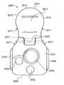
- FIG. 22Ashows a perspective view of a further embodiment of implant of the invention.
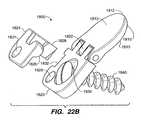
- FIG. 22Bshows a perspective exploded view of the embodiment of the invention shown in FIG. 22A .
- FIG. 23Adepicts a posterior view of the embodiment of the implant of the invention shown in FIG. 22A .
- FIG. 23Bshows a posterior view of a locking plate of the embodiment of the implant of the invention shown in FIG. 22A .
- FIG. 24Adepicts a lateral side view of the embodiment of the implant of the invention shown in FIG. 22A .
- FIG. 24Bshows a lateral side view of the keel of the locking plate of the embodiment of the implant of the invention shown in FIG. 22A .
- FIG. 25Ashows a perspective view of a further embodiment of the implant of the invention.
- FIG. 25Bshows a side view of the embodiment of the implant of the invention in FIG. 25A , having a curved, uniformly-thick artificial facet joint spacer or inter-facet spacer including a tapered end
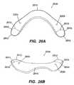
- FIG. 26Ashows a perspective view of a further embodiment of the implant of the invention.
- FIG. 26Bshows a posterior perspective view of the embodiment of the implant of the invention depicted in FIG. 26A .
- FIG. 27Adepicts a side view of the embodiment of the implant of the invention shown in FIGS. 26A and 26B .
- FIG. 27Bshows a posterior view of the embodiment of the implant of the invention shown in FIGS. 26A , 26 B, and 27 A, implanted in the cervical spine.
- FIG. 28Adepicts a posterior perspective view of a further embodiment of the implant of the invention.
- FIG. 28Bdepicts a side view of the embodiment of the implant of the invention shown in FIG. 28A .
- FIG. 29Adepicts a side view of an embodiment of a sizing tool of the invention.
- FIG. 29Bdepicts a top view of an embodiment of the sizing tool of the invention depicted in FIG. 29A .
- FIG. 29Cdepicts a perspective view of an embodiment of the sizing tool of the invention depicted in FIGS. 29A-B .
- FIG. 29Ddepicts a side view of the head of the sizing tool of the invention depicted in FIG. 29A
- FIG. 29Edepicts a cross-sectional view of the head of the sizing tool of the invention depicted in FIGS. 29A-C .
- FIG. 30is a flow diagram of an embodiment of a method of the invention.
- FIG. 31Ais posterior view of a further embodiment of the implant of the invention.
- FIG. 31Bis a side view of an embodiment of a locking screw of the implant of the invention depicted in FIG. 31A .
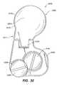
- FIG. 32is a posterior view of a further embodiment of the implant of the invention.
- FIGS. 33A and 33Bdepict initial and final insertion positions of the embodiment of the invention depicted in FIG. 32 .
- FIG. 34Ais a posterior view of a further embodiment of the implant of the invention.
- FIG. 34Bis a side view of a further embodiment of the implant of the invention.
- FIG. 35Ais a perspective view of an embodiment of the implantation tool of the invention.
- FIG. 35Bis a perspective view of the engagement head of the implantation tool of the invention.
- Embodiments of the present inventionprovide for a minimally invasive surgical implantation method and apparatus for cervical spine implants that preserves the physiology of the spine.
- embodimentsprovide for distracting the cervical spine to increase the foraminal dimension in extension and neutral positions.
- Such implantswhen implanted in the cervical facet joints, distract, or increase the space between, the vertebrae to increase the foraminal area or dimension, and reduce pressure on the nerves and blood vessels of the cervical spine.
- the facet joints in the spineare formed between two vertebrae as follows.
- Each vertebrahas four posterior articulating surfaces: two superior facets and two inferior facets, with a superior facet from a lower vertebra and an inferior facet of an upper vertebra forming a facet joint on each lateral side of the spine.
- the upward inclination of the superior articular surfaces of the facet jointsallows for considerable flexion and extension, as well as for lateral mobility.
- Each facet jointis covered by a dense, elastic articular capsule, which is attached just beyond the margins of the articular facets. The capsule is larger and looser in the cervical spine than in the thoracic and lumbar spine.
- the inside of the capsuleis lined by a synovial membrane which secretes synovial fluid for lubricating the facet joint.
- the exterior of the joint capsuleis surrounded by a capsular ligament. It is this ligament and the joint capsule that must be cut in the embodiments of the method described herein for inserting the artificial facet joint.
- an implanted interfacet spacer of 1.5 mm to 2.5 mm in widthcan result in interfacet distraction that increases foraminal dimension in extension and neutral.
- Other interfacet spacer dimensionsalso are contemplated by the invention described herein below.
- the present embodimentsalso preserve mobility of the facet joints.
- Embodiments of the present inventionaccommodate the distinct anatomical structures of the spine, minimize further trauma to the spine, and obviate the need for invasive methods of surgical implantation.
- Embodiments of the present inventionalso address spinal conditions that are exacerbated by spinal extension.
- FIG. 1shows a simplified diagram of a portion of the cervical spine, focusing on a cervical facet joint 1 formed between two adjacent cervical vertebrae.
- the spinous processes 3are located posteriorly and the vertebral bodies 5 are located anteriorly, and a nerve root canal 7 is visible.
- Each vertebrahas four posterior articulating surfaces: two superior facets and two inferior facets, with a superior facet from a lower vertebra and an inferior facet of an upper vertebra forming a facet joint on each lateral side of the spine.
- the upward inclination of the superior articular surfaces of the facet jointsallows for considerable flexion and extension, as well as for lateral mobility.
- Each facet jointis covered by a dense, elastic articular capsule, which is attached just beyond the margins of the articular facets.
- the capsuleis large and looser in the cervical spine than in the thoracic and lumbar spine.
- the inside of the capsuleis lined by a synovial membrane which secretes synovial fluid for lubricating the facet joint.
- the exterior of the joint capsuleis surrounded by a capsular ligament. It is this ligament that may be pushed out of the way in the embodiments of the method for inserting the artificial facet joint, described herein.
- FIG. 2depicts cervical foraminal stenosis. From the drawing, the nerve root canal 7 is narrowed relative to the nerve root canal 7 depicted in FIG. 1 .
- the spinal canal and/or intervertebral foraminaalso can be narrowed by stenosis. The narrowing can cause compression of the spinal cord and nerve roots.
- FIG. 3Ashows a first embodiment 100 of the present invention, which is meant to distract at least one facet joint, in order to increase the dimension of the neural foramen while retaining facet joint mobility.
- the wedge-shaped embodiment or inter-facet spacer 100is a wedge-shaped implant that can be positioned in the cervical facet joint 101 to distract the joint and reverse narrowing of the nerve root canal 107 .
- the implantis positioned with the narrow portion of the wedge facing anteriorly.
- implants in accordance with the present invention, and/or portions thereofcan be fabricated from somewhat flexible and/or deflectable material.
- the implant and/or portions thereofcan be made out of a polymer, such as a thermoplastic.
- the implantcan be made from polyketone, known as polyetheretherketone (“PEEK”).
- PEEKpolyetheretherketone
- the implantcan be made from PEEK 450G, which is an unfilled PEEK approved for medical implantation available from Victrex of Lancashire, Great Britain. Other sources of this material include Gharda located in Panoli, India.
- PEEKhas the following approximate properties:
- the material specifiedhas appropriate physical and mechanical properties and is suitable for carrying and spreading a physical load between the adjacent spinous processes.
- the implant and/or portions thereofcan be formed by extrusion, injection, compression molding and/or machining techniques.
- the implantcan comprise, at least in part, titanium or stainless steel, or other suitable implant material which is radiopaque, and at least in part a radiolucent material that does not show up under x-ray or other type of imaging.
- the physiciancan have a less obstructed view of the spine under imaging, than with an implant comprising radiopaque materials entirely.
- the implantneed not comprise any radiolucent materials.
- the material selectedalso can be filled.
- other grades of PEEKare also available and contemplated, such as 30% glass-filled or 30% carbon-filled, provided such materials are cleared for use in implantable devices by the FDA, or other regulatory body.
- Glass-filled PEEKreduces the expansion rate and increases the flexural modulus of PEEK relative to that unfilled PEEK.
- the resulting productis known to be ideal for improved strength, stiffness, or stability.
- Carbon-filled PEEKis known to enhance the compressive strength and stiffness of PEEK and to decrease its expansion rate. Carbon-filled PEEK offers wear resistance and load-carrying capability.
- the implantis manufactured from PEEK, available from Victrex.
- PEEKpolyetherketoneketone
- the spaceralso can be comprised of polyetherketoneketone (“PEKK”).
- PEKKpolyetherketoneketone
- Other material that can be usedinclude polyetherketone (“PEK”), polyetherketoneetherketoneketone (“PEKEKK”), and polyetheretherketoneketone (“PEEKK”), and generally a polyaryletheretherketone.
- the embodiment 200 of the implanthas a joint insert or inter-facet spacer 210 , also herein referred to as an artificial facet joint or inter-facet spacer, that is positioned in the cervical facet joint 101 .
- the joint insert or inter-facet spacer 210can be wedge-shaped with the narrow part of the wedge facing anteriorly.
- the joint insert or inter-facet spacer 210need not be wedge-shaped but can be of substantially uniform thickness, the thickness determined by an individual patient's need for distraction of the cervical facet joint 201 .
- one objective of this embodimentis facet joint distraction, and joint mobility after implantation.
- the joint insert 210is continuous with a posterior sheath 220 bent at an angle from the joint insert or inter-facet spacer 210 to align substantially parallel with the bone.
- the posterior sheathcan lie against the lamina, preferably against the lateral mass.
- the posterior sheath 220can have a bore 230 which can accept a bone screw 240 .
- the bore 230can accept any other appropriate and/or equivalent fixation device capable of fixing the embodiment 200 to the spine.
- the deviceis thereby affixed to the vertebra, preferably by fixing to the lateral mass.
- FIG. 5shows embodiment 300 , which is the use of two embodiments 200 , each fixed to one of two adjacent cervical vertebrae.
- the implanted facet jointis distracted and joint mobility is retained.
- a joint insert or inter-facet spacer 310 from each of the two implantsis inserted and positioned in the cervical facet joint 301 .
- the joint inserts 310are substantially flat and parallel to each other and are not wedge-shaped.
- the joint inserts or inter-facet spacers 310can together define a wedge-shaped insert that is appropriate for the patient.
- the two joint inserts or inter-facet spacers 310 combinedcan have, by way of example, the shape of the joint insert or inter-facet spacers 210 in FIG. 4 .
- Embodiment 300then can be fixed to the spine with a screw 340 or any other appropriate fixation device, inserted through a bore 330 in the posterior sheath 320 .
- the posterior sheath 320can be threaded to accept a screw.
- the screwcan be embedded in the lamina, preferably in the lateral mass, where possible.
- FIG. 6depicts a cervical spine lordosis.
- FIG. 7demonstrates an embodiment 400 which contemplates positioning two implants to correct for this spinal abnormality while retaining facet joint mobility.
- the joint insert or inter-facet spacer 410 of each implantis shaped so that it is thicker at its anterior portion.
- the implantscan be shaped to be thicker at the posterior ends, for example as depicted in FIG. 3A .
- each implantis bent at an angle from the joint insert or inter-facet spacer 410 to be positioned adjacent to the lateral mass and/or lamina, and has a bore 430 to accept a screw 440 or other appropriate and/or equivalent fixation means to fix the embodiment 400 to the spine, preferably to the lateral mass.
- the placement of two joint inserts or inter-facet spacers 410 in the cervical facet joint 401distracts the facet joint, which shifts and maintains the vertebrae into a more anatomical position to preserve the physiology of the spine.
- FIG. 8shows a further embodiment 500 of the implant of the invention, wherein the joint insert or inter-facet spacer 510 has a keel 550 on an underside of the joint insert or inter-facet spacer 510 .
- the keel 550can be made of the same material or materials set forth above. The surfaces of the keel 550 can be roughened in order to promote bone ingrowth to stabilize and fix the implant 500 .
- the keel 550can be coated with materials that promote bone growth such as, for example, bone morphogenic protein (“BMP”), or structural materials such as hyaluronic acid “HA,” or other substances which promote growth of bone relative to and into the keel 550 .
- BMPbone morphogenic protein
- HAhyaluronic acid
- the keel 550can be embedded in the facet bone, to facilitate implant retention.
- the keel 550can be placed into a channel in the facet bone.
- the channelcan be pre-cut.
- Teeth(not shown), preferably positioned posteriorly, also may be formed on the keel 550 for facilitating retention of the implant 500 in the cervical facet joint 501 .
- the joint insert or inter-facet spacer 510can be substantially flat or wedge-shaped, depending upon the type of distraction needed, i.e., whether distraction is also necessary to correct abnormal curvature or lack of curvature in the cervical spine. Because the joint is not fused, mobility is retained, as with the embodiments described above and herein below.
- FIG. 9illustrates that a further embodiment 600 of the implant of the invention can have both screw fixation and a keel 650 for stability and retention of the implant 600 .
- the joint insert or inter-facet spacer 610is continuous with a posterior sheath 620 having a bore hole 630 to accept a screw 640 which passes through the bore 630 and into the bone of the vertebrae, preferably into the lateral mass, or the lamina.
- the bore 630can be threaded or not threaded where it is to accept a threaded screw or equivalent device. Alternatively, the bore 630 need not be threaded to accept a non-threaded equivalent device.
- the keel 650is connected with the joint insert or inter-facet spacer 610 and embeds in the bone of the cervical facet joint 601 to promote implant retention.
- FIG. 10A further alternative embodiment 700 is illustrated in FIG. 10 .
- the joint insert 710has on a lower side at least one tooth 760 .
- a plurality of teeth 760is preferable.
- the teeth 760are able to embed in the bone of the cervical facet joint 701 to facilitate retention of the implant 700 in the joint 701 .
- the teeth 760can face in a direction substantially opposite the direction of insertion, for retention of the implant 700 .
- the joint insert or inter-facet spacer 710can be wedge-shaped or substantially even in thickness, depending upon the desired distraction. Because the implant distracts and is retained without fusion, facet joint mobility is retained.
- FIG. 11depicts a further embodiment 800 of the implant of the invention.
- the joint insert or inter-facet spacer 810is continuous with a posterior sheath 820 having a bore 830 for accepting a fixation device 840 , as described above.
- the fixation device 840can be a screw which fits into a threaded bore 830 ; alternatively, the fixation device 830 can be any other compatible and appropriate device.
- This embodiment 800further combines at least one tooth 860 on an underside of the joint insert or inter-facet spacer 810 with the posterior sheath 820 , bore 830 and fixation device 840 to address fixation of the implant 800 in a cervical facet joint 801 .
- the implant 800can have a plurality of teeth 860 on the underside of the joint insert or inter-facet spacer 810 .
- FIG. 12shows yet another embodiment 900 of an implant of the present invention.
- the joint inserts or inter-facet spacers 910 of two implants 900are positioned in a cervical facet joint 901 .
- the joint inserts or inter-facet spacers 910can be wedge-shaped as needed to restore anatomical curvature of the cervical spine and to distract, or the joint inserts or inter-facet spacers 910 can be of substantially uniform thickness.
- the implants 900each comprise a joint insert or inter-facet spacer 910 with an outer surface 970 that interacts with the bone of the cervical facet joint 901 .
- the surface 970 that interacts with the boneis the upper surface 970 and on the lower implant 900 , the surface 970 that interacts with the bone is the lower surface 970 .
- Each surface 970can comprise a bone ingrowth surface 980 to create a porous surface and thereby promote bone ingrowth and fixation.
- One such treatmentcan be with plasma spray titanium, and another, with a coating of sintered beads.
- the implant 900can have casted porous surfaces 970 , where the porous surface is integral to the implant 900 .
- the surfaces 970can be roughened in order to promote bone ingrowth into these defined surfaces of the implants 900 .
- the surfaces 970can be coated with materials that promote bone growth such as for example bone morphogenic protein (“BMP”), or structural materials such as hyaluronic acid (“HA”), or other substances which promote growth of bone on other external surfaces 970 of the implant 900 .
- BMPbone morphogenic protein
- HAhyaluronic acid
- FIG. 13depicts yet another embodiment 1000 of the implant of the present invention.
- the joint inserts or inter-facet spacers 1010 of two implants 1000are positioned in a cervical facet joint 1001 .
- the joint inserts or inter-facet spacers 1010can be wedge-shaped as needed to restore anatomical curvature of the cervical spine and to distract, or the joint inserts or inter-facet spacers 1010 can be of substantially uniform thickness.
- the implants 1000each comprise a joint insert or inter-facet spacer 1010 with an outer surface 1070 that interacts with the bone of the cervical facet joint 1001 .
- each outer surface 1070can comprise a bone ingrowth surface 1080 to create a porous surface and thereby promote bone ingrowth and fixation, without facet joint fusion and loss of mobility.
- the bone ingrowth surface 1080can be created with plasma spray titanium, and/or with a coating of sintered beads.
- the implant 1000can have casted porous surfaces 1070 , where the porous surface is integral to the implant 1000 .
- the surfaces 1070can be roughened in order to promote bone ingrowth into these defined surfaces of the implants 1000 .
- the surfaces 1070can be coated with materials that promote bone growth such as for example BMP, or structural materials such as HA, or other substances which promote growth of bone on other external surfaces 1070 of the implant 1000 .
- the implant 1000can have a posterior alignment guide 1090 .
- the posterior alignment guides 1090 of each implant 1000can be continuous with the joint inserts or inter-facet spacers 1010 .
- the posterior alignment guidessubstantially conform to the bone of the vertebrae when the joint inserts or inter-facet spacers 1010 are inserted into the cervical facet joint 1001 .
- the posterior alignment guides 1090are used to align the implants 1000 so that the joint inserts 1010 contact each other and not the bones of the cervical facet joint 1001 when the joint inserts 1010 or inter-facet spacers are positioned in the cervical facet joint 1001 .
- FIG. 14depicts a further embodiment 1100 of the implant of the present invention.
- the joint inserts 1110 of two implants 1100are inserted into the cervical facet joint 1101 .
- Each of the joint inserts or inter-facet spacers 1110is continuous with a cervical facet joint extender or facet-extending surface 1192 .
- the bone contacting surfaces 1170 of the joint inserts or inter-facet spacers 1110are continuous with, and at an angle to, the bone contacting surfaces 1193 of the cervical facet joint extenders 1192 , so that the cervical facet joint extenders 1192 conform to the bones of the vertebrae exterior to the cervical facet joint 1101 .
- the conformity of the cervical facet joint extenders 1192is achieved for example by forming the cervical facet joint extenders 1192 so that when the join inserts or inter-facet spacers 1110 are positioned, the cervical facet joint extenders 1192 curve around the bone outsider the cervical facet joint 1101 .
- the cervical facet joint extendershave a second surface 1184 that is continuous with the joint articular surfaces 1182 of the joint inserts or inter-facet spacers 1110 .
- the second surfaces 1184extend the implant 1100 posteriorly to expand the joint articular surfaces 1182 and thereby to increase contact and stability of the spine at least in the region of the implants 1100 . It is to be understood that such facet joint extenders 1192 can be added to the other embodiments of the invention described and depicted herein.
- each of two implants 1200has a joint insert or inter-facet spacer 1210 positioned in a cervical facet joint 1201 .
- the joint inserts or inter-facet spacers 1210can be wedge-shaped as needed to restore anatomical curvature of the cervical spine and to distract, or the joint inserts or inter-facet spacers 1210 can be of substantially uniform thickness.
- the implants 1200each comprise a joint insert 1210 with an outer surface 1270 that interacts with the bone of the cervical facet joint 1001 .
- each outer surface 1270can comprise a bone ingrowth surface 1280 to create a porous surface and thereby promote bone ingrowth and fixation.
- the bone ingrowth surface 1280can be created with plasma spray titanium, and/or with a coating of sintered beads.
- the implant 1200can have casted porous surfaces 1270 , where the porous surface is integral to the implant 1200 .
- the surfaces 1270can be roughened in order to promote bone ingrowth into these defined surfaces of the implants 1200 .
- the surfaces 1270can be coated with materials that promote bone growth such as for example BMP, or structural materials such as HA, or other substances which promote growth of bone on other external surfaces 1270 of the implant 1200 .
- Screw fixation or other appropriate fixationalso can be used with implants 1200 for fixation in the cervical facet joint 1201 .
- the joint insert or inter-facet spacer 1210is continuous with a posterior sheath 1220 bent at an angle from the joint insert or inter-facet spacer 1210 to align substantially parallel with the bone, preferably the lateral mass or lamina.
- the posterior sheath 1220can have a bore 1230 which can accept a bone screw 1240 , preferably into the lateral mass or lamina.
- the bore 1230can accept any other appropriate and/or equivalent fixation means for fixing the embodiment 1200 to the spine.
- FIG. 16depicts a further preferred embodiment of the present invention.
- two joint inserts or inter-facet spacers 1310are positioned in the cervical facet joint 1301 .
- the joint insertseach have outer surfaces 1370 that interact with the bone of the vertebrae forming the cervical facet joint.
- These outer surfaces 1370 of the embodiment 1300can be treated to become bone ingrowth surfaces 1380 , which bone ingrowth surfaces 1380 contribute to stabilizing the two joint inserts or inter-facet spacers 1310 of the implant 1300 .
- the bone ingrowth surface 1380can be created with plasma spray titanium, and/or with a coating of sintered beads.
- the implant 1300can have casted porous surfaces 1370 , where the porous surface is integral to the implant 1300 .
- the surfaces 1370can be roughened in order to promote bone ingrowth into these defined surfaces of the implants 1300 .
- the surfaces 1370can be coated with materials that promote bone growth such as for example BMP, or structural materials such as HA, or other substances which promote growth of bone on other external surfaces 1370 of the implant 1300 . This fixation stabilizes the implant 1300 in the facet joint without fusing the joint, and thus the implant preserves joint mobility, while accomplishing distraction and increasing foraminal dimension.
- articular inner surfaces 1382 of the implants 1300can be formed from a metal and polyethylene, the material allowing flexibility and providing for forward bending/flexion and backward extension of the cervical spine.
- the embodiment 1300 of FIG. 16can be made in at least two configurations.
- the first configurationincludes a flexible spacer 1382 made, by way of example, using polyethylene or other suitable, flexible implant material.
- the flexible spacer 1382can be permanently affixed to the upper and lower joint insert or inter-facet spacer 1310 .
- the spacer 1382can be flat or wedge-shaped or have any other shape that would correct the curvature of the spine.
- the spacer 1382can be affixed to only the upper insert or inter-facet spacer 1310 or to only the lower insert 1310 .
- a spacer 1382can be affixed to each of an upper insert or inter-facet spacer 1310 and a lower insert or inter-facet spacer 1310 with the upper insert or inter-facet spacer 1310 and the lower insert or inter-facet spacer 1310 being separate units.
- FIG. 17shows a further preferred embodiment of the implant of the present invention.
- the implanthas a roller 1496 mounted on a joint insert or inter-facet spacer 1410 , the roller being a further means of preserving joint mobility while accomplishing distraction.
- Both the roller 1496 and the joint insert or inter-facet spacer 1410are positioned in the cervical facet joint 1401 .
- the joint insert or inter-facet spacer 1410as in other embodiments has a bone-facing surface 1470 and joint articular surface 1482 .
- the bone-facing surface 1470can interact with the lower bone of the cervical facet joint 1401 .
- the bone-facing surfacecan interact with the upper bone of the cervical facet joint 1401 .
- roller 1496rotates in a cavity in the joint insert 1410 , and interacts with the top bone of the cervical facet joint 1401 .
- the roller 1496rotates in a cavity in the joint insert or inter-facet spacer 1410 and interacts with the lower bone of the cervical facet joint 1401 .
- the rotation of the roller 1496allows flexion and extension of the cervical spine.
- a rollersuch as roller 1496 can be secured to an upper and a lower insert such as inserts 410 in FIG. 7 .
- a plurality of rollers 1496also is possible.
- FIG. 19depicts a further embodiment of the implant of the present invention.
- two implants 1500are implanted in the cervical facet joint 1501 .
- Screw fixation or other appropriate fixationis used with implants 1500 for fixation in the cervical facet joint 1501 .
- the joint insert or inter-facet spacer 1510is continuous with a posterior sheath 1520 bent at an angle from the joint insert or inter-facet spacer 1510 to align substantially parallel with the bone, preferably the lateral mass or lamina.
- the posterior sheath 1520 of each implant 1500can have a bore 1530 which can accept a bone screw 1540 , preferably into the lateral mass or lamina.
- the bore 1530can accept any other appropriate and/or equivalent fixation means for fixing the embodiment 1500 to the spine.
- the head of the screw 1540 in each posterior sheath 1520 of each implant 1500has a groove 1598 or other mechanism for retaining an elastic band 1597 .
- the elastic band 1597is looped around each of the two screws 1540 to restrain movement of the cervical spine without eliminating facet joint mobility.
- the band 1597preferably can restrain flexion and lateral movement.
- the elastic band 1597can be made of a biocompatible, flexible material.
- FIG. 20shows an alternative to use of an elastic band as in FIG. 19 .
- the elastic bandis replaced with a spring restraint 1699 , which extends between the heads of two screws 1640 , one screw fixing each of two implants 1600 in the cervical facet joint 1601 .
- FIG. 21shows another alternative to using an elastic band and/or a spring as in FIG. 19 or 20 .
- magnets 1795are used for restraint between the two screws 1740 .
- the magnet 1795can either be comprised of two opposing magnetic fields or two of the same magnetic fields to operate to restrain movement.
- the head of one of the two screws 1740is magnetized, and the head of the other screw 1740 is magnetized with either the same or opposite field. If the magnets 1795 have the same polarity, the magnets 1795 repel each other and thus limit extension. If the magnets 1795 have opposite polarities, the magnets 1795 attract each other and thus limit flexion and lateral movement.
- FIGS. 22A-24Bdepict a further embodiment 1800 of the implant of the present invention.
- a facet joint spacer (or insert) or inter-facet spacer (or insert) 1810is connected with a lateral mass plate (also referred to as an anchoring plate) 1820 with a hinge 1822 .
- the hinge 1822allows the lateral mass plate 1820 to bend at a wide range of angles relative to the artificial facet joint and preferably at an angle of more than 90 degrees, and this flexibility facilitates positioning and insertion of the facet joint spacer (or insert) or inter-facet spacer (or insert) 1810 into a patient's facet joint, the anatomy of which can be highly variable among individuals.
- the hinge 1822further facilitates customizing the anchoring of the implant, i.e., the positioning of a fixation device.
- the hingeenables positioning of the lateral mass plate 1820 to conform to a patient's cervical spinal anatomy, and the lateral mass plate 1820 accepts a fixation device to penetrate the bone.
- the facet joint spacer (or insert) or inter-facet spacer (or insert) 1810can be curved or rounded at a distal end 1812 ( FIG. 23A ), and convex or dome-shaped on a superior surface 1813 to approximate the shape of the bone inside the facet joint.
- the inferior surface 1815can be flat or planar. Alternatively, the inferior surface 1815 can be concave. As another alternative, the inferior surface 1815 can be convex.
- the lateral mass plate 1820when implanted in the spine, is positioned outside the facet joint, preferably against the lateral mass or against the lamina.
- the lateral mass plate 1820has a bore 1830 therethrough.
- the bore 1830can accept a bone screw 1840 , also referred to as a lateral mass screw, to secure the lateral mass plate 1820 preferably to the lateral mass or alternatively to another part of the spine, and thus to anchor the implant.
- the lateral mass screw 1840preferably has a hexagonal head to accept an appropriately-shaped wrench. As described below, the head accepts a compatible probe 1826 from a locking plate 1824 .
- the locking plate 1824includes a keel 1828 with a wedge shaped distal end to anchor the implant, preferably in the lateral mass or in the lamina, outside the facet joint and to prevent rotation of the lateral mass plate 1820 and the locking plate 1824 .
- the keel 1828aligns with a groove 1823 through an edge of the lateral mass plate 1820 to guide and align the keel 1828 as the keel 1828 cuts into a vertebra.
- the locking plate 1824includes a probe 1826 that fits against the head of the lateral mass screw 1840 .
- the locking platefurther includes a bore 1831 that can accept a machine screw (not shown) which passes through to an aligned bore 1829 in the lateral mass plate 1820 to hold the locking plate 1824 and the lateral mass plate 1820 together without rotational displacement relative to each other.
- the locking plate 1824thus serves at least two functions: (1) maintaining the position of the lateral mass screw 1840 with the probe 1826 , so that the screw 1840 does not back out; and (2) preventing rotation of the implant with the keel 1828 and machine screw relative to the cervical vertebra or other vertebrae.
- the locking plate 1824can include a probe with barbs that can be inserted into a port in the lateral mass plate. The barbs can become engaged in ribs that define the side walls of the port in the lateral mass plate.
- the lateral mass plate 1920includes a recessed area 1922 for receiving the locking plate 1924 so that the locking plate 1924 is flush with the upper surface 1925 of the lateral mass plate 1920 when the probe 1926 is urged against the lateral mass screw 1940 and the keel 1928 is inserted into the lateral mass or the lamina of the vertebra.
- the shape and contours of the facet joint spacer (or insert) or inter-facet spacer (or insert) 1910can facilitate insertion of the facet joint spacer (or insert) or inter-facet spacer (or insert) 1910 into the cervical facet joint.
- the facet joint spacer (or insert) or inter-facet spacer (or insert) 1910has a rounded distal end 1912 .
- the distal end 1912is tapered in thickness to facilitate insertion.
- the tapered distal end 1912meets and is continuous with a proximal mid-section 1916 which, in this preferred embodiment, has a uniform thickness, and is connected flexibly, preferably with a hinge 1922 , to the lateral mass plate 1920 , as described above.
- the facet joint spacer (or insert) or inter-facet spacer (or insert) 1910is curved downward, causing a superior surface 1913 of the facet joint spacer (or insert) or inter-facet spacer (or insert) 1910 to be curved.
- the curvecan cause the superior surface 1913 to be convex, and the convexity can vary among different implants 1900 to suit the anatomical structure of the cervical facet joint(s) of a patient.
- An inferior surface 1915accordingly can be preferably concave, flat, or convex.
- the curved shape of the implantcan fit the shape of a cervical facet joint, which is comprised of an inferior facet of an upper vertebra and a superior facet of a lower adjacent vertebra.
- the convex shape of the superior surface 1913 of the facet joint spacer (or insert) or inter-facet spacer (or insert) 1910fits with a concave shape of the inferior facet of the upper cervical vertebrae.
- the concave shape of the inferior surface 1915 of the facet joint spacer (or insert) or inter-facet spacer (or insert) 1910fits with the convex shape of the superior facet of the cervical vertebrae.
- the degree of convexity and concavity of the facet joint spacer (or insert) or inter-facet spacer (or insert) inferior and superior surfacescan be varied to fit a patient's anatomy and the particular pairing of adjacent cervical vertebrae to be treated.
- a less-curved facet joint spacer (or insert) or inter-facet spacer (or insert) 1910can be used where the patient's cervical spinal anatomy is sized (as described below) and found to have less convexity and concavity of the articular facets.
- the input for the right and left facet jointwill be similarly shaped.
- the width of the mid-section 1916is from 1.5 mm to 2.5 mm.
- FIGS. 22A-24Bis similar to the embodiment shown in FIGS. 25A , 25 B. Accordingly the remaining elements on the 1900 series of element numbers is preferably substantially similar to the described elements in the 1800 series of element numbers, as set forth above. Thus, by way of example, elements 1923 , 1928 , 1929 and 1930 are similar, respective elements 1823 , 1828 , 1829 and 1830 .
- FIG. 30is a flow chart of the method of insertion of an implant of the invention.
- the embodiment 1800 or 1900 of the present inventionpreferably is inserted in the following manner (only elements of the embodiment 1800 will be set forth herein, for purposes of the written description of a method of the invention).
- a sizing tool 2200(see FIGS. 29A-C ) can be inserted to select the appropriate size of an implant of the invention for positioning in the cervical facet joint. This step may be repeated as necessary with, if desired, different sizes of the tool 2200 until the appropriate size is determined. This sizing step also distracts the facet joint and surrounding tissue in order to facilitate insertion of the implant.
- the natural or artificial facet joint spacer or inter-facet spacer 1810is urged between the facets into the facet joint.
- the facetitself is somewhat shaped like a ball and socket joint. Accordingly, in order to accommodate this shape, the natural or artificial joint spacer or inter-facet spacer 1810 can have a rounded leading edge shaped like a wedge or tissue expander to cause distraction of the facet joint as the natural or natural or artificial facet joint spacer or inter-facet spacer or inter-facet spacer is urged into the facet joint of the spine.
- the natural or artificial facet joint spacer or inter-facet spacer 1810also includes the convex surface 1813 in order to more fully accommodate the shape of the facet joint of the spine.
- the lateral mass plate 1820is pivoted downward about the hinge 1822 adjacent to the vertebrae and preferably to the lateral mass or to the lamina.
- the lateral mass plate 1820may be disposed at an angle relative to the natural or artificial facet joint spacer or inter-facet spacer 1810 for a representative spine configuration. It is to be understood that as this embodiment is hinged the final position of the lateral mass plate 1820 relative to the natural or artificial facet joint spacer or inter-facet spacer 1810 will depend on the actual spine configuration.
- embodiments of the inventioncan be made without a hinge, as long as the connection between the natural or artificial facet joint spacer or inter-facet spacer and the lateral mass plate is flexible enough to allow the lateral mass plate to be bent relative to the natural or artificial facet joint spacer or inter-facet spacer in order to fit the anatomy of the patient.
- a borecan be drilled in the bone to accommodate the bone screw 1824 .
- the screw 1824can be self-tapping.
- the screwis then placed through the bore 1830 and secured to the bone, preferably the lateral mass or the lamina, thereby holding the natural or artificial facet joint spacer or inter-facet spacer 1810 in place.
- the locking plate 1824is positioned over the lateral mass plate 1820 . So positioned, the probe 1826 is positioned through the bore 1830 and against the head of the bone screw to keep the bone screw from moving.
- the keel 1828having a sharp chisel-shaped end, preferably can self-cut a groove in the bone so that the keel 1828 is locked into the bone as the keel 1828 is aligned by, and received in, a groove 1831 of the lateral mass plate 1820 .
- a groovecan be pre-cut in the bone to receive the keel 1828 .
- the bore 1829 of the locking plate 1824aligns with the threaded bore 1831 of the lateral mass plate 1820 and a machine screw can be inserted to lock the locking plate relative to the lateral mass plate.
- the implantis between the C5 and C6 vertebrae level, or the C6 and C7 vertebrae level. It is noted that two implants preferably will be implanted at each level between vertebrae. That is, an implant 1800 will be placed in a right facet joint and also in a left facet joint when viewed from a posterior view point.
- This procedurecan be used to increase or distract the foraminal area or dimension of the spine in an extension or in neutral position (without having a deleterious effect on cervical lordosis) and reduce the pressure on the nerves and blood vessels. At the same time this procedure preserves mobility of the facet joint.
- FIGS. 26A-27Bshow a further embodiment of the implant of the invention, with the embodiment 2000 implanted in the cervical spine as depicted in FIGS. 27A and 27B .
- the implant 2000comprises a first natural or artificial facet joint spacer or inter-facet spacer 2010 and a second natural or artificial facet joint spacer or inter-facet spacer 2010 .
- Each natural or artificial facet joint spacer or inter-facet spacercan have a distal end 2012 that is tapered or wedge-shaped in a way that facilitates insertion into the cervical facet joints on both sides of two adjacent cervical vertebrae at the same level.
- the natural or artificial facet joint spacers or inter-facet spacersfurther can be dome-shaped, or convex on a superior surface 2013 , to approximate the shape of the cervical facets of the cervical facet joints.
- the first and second natural or artificial facet joint spacer or inter-facet spacers 2010are bridged together by a collar 2015 .
- the collar 2015passes between the spinous processes of the adjacent cervical vertebrae.
- the implantcan preferably be “V” shaped or “boomerang” shaped.
- the entire implant 2000 or the collar 2015 of the implantcan be made of a flexible material such as titanium, so that it is possible to bend the collar 2015 so that it conforms preferably to the shape of the lateral mass or the lamina of the cervical vertebrae of the patient and thereby holds the implant in place with the natural or artificial facet joint spacer or inter-facet spacer 2010 inserted in the cervical facet joints.
- Bores 2029are preferably are provided through implant 2000 adjacent to the natural or artificial facet joint spacer or inter-facet spacer 2010 respectively. These bores 2029 can receive bone screws to position the implant 2000 against the lateral mass or the lamina as shown in FIGS. 27A , 27 B.
- the description of the embodiment 2100 , in FIGS. 28A , 28 Bprovide further details concerning the method of affixing the implant 2000 to the vertebrae.
- the implant 2100also can be made of PEEK or other materials as described herein.
- Embodiment 2000(the “boomerang” shape depicted in FIG. 27B ) further can have a locking plate as, for example, the locking plate 1824 in FIG. 22A .
- the locking plate for embodiment 2000can have the same features as locking plate 1824 , that is: (1) a probe 1826 that interacts with the bone screws to prevent the bone screws from backing out of the bone, the likely consequence of which would be displacement of the implant 2000 ; and (2) a keel 1828 with a chisel end to embed in the bone and thus to prevent rotational displacement of the implant.
- a chiselmay not serve the same purpose as with the embodiments set forth above, which lack a collar stabilized by two bone screws. Therefore, a locking plate on embodiment 2000 can be provided without a keel.
- FIGS. 28A and 28Bdepict a further embodiment of the implant of the invention 2100 .
- the collar 2115can be made of a flexible material such as titanium, of a substantially inflexible material, or of other materials described herein. Substantial flexibility can also be derived from connecting a first natural or artificial facet joint spacer or inter-facet spacer 2110 with the collar 2115 using a first hinge 2117 , and connecting a second natural or artificial facet joint spacer or inter-facet spacer 2110 with the collar 2115 using a second hinge 2117 .
- the collar 2115can be pivoted downward to conform to a particular patient's cervical spinal anatomy. In other words, the degree of pivoting will vary among different patients, and the first hinge 2117 and second hinge 2117 allow the implant 2100 to accommodate the variance.
- the collar 2115can have a first bore 2129 inferior to the first hinge 2117 , and a second bore 2129 inferior to the second hinge 2117 .
- a first bone screwpenetrates the first bore 2130 and into the lateral mass or the lamina
- the second bone screwpenetrates the second bore 2130 and into the lateral mass or the lamina, the first and second bone screws serving to anchor the implant.
- a bore, preferably in the lateral mass,can be drilled for the first bone screw and for the second bone screw.
- the bone screwscan be self-tapping.
- a first locking platesimilar to the plate 1924 ( FIG.
- the first locking platecan block the first bone screw with a probe and the second locking plate can block to the second bone screw with a probe.
- embodiments 2000 and 2100also can be configured for accommodating treatment of cervical spinal stenosis and other cervical spine ailments where only a single cervical facet joint between adjacent vertebrae requires an implant, i.e., where treatment is limited to one lateral facet joint.
- the collar 2015 , 2115extends medially without extending further to join a second natural or artificial facet joint spacer or inter-facet spacer 2010 , 2110 .
- the implantcomprises a single hinge 2117 , and the collar 2115 has only one bore 2129 to accept one bone screw to secure the implant 2100 .
- FIGS. 29A-Edepict a sizing and distracting tool 2200 of the invention.
- Sizing tool 2200has a handle 2203 and a distal head 2210 that is shaped as a natural or artificial facet joint spacer or inter-facet spacer (e.g., 1810 ) of an implant of the invention. That is, the head 2210 preferably will have essentially the same features as the natural or artificial facet joint spacer or inter-facet spacer 1810 , but the dimensions of the head 2210 will vary from one tool 2200 to the next, in order to be able to use different versions of the sizing tool 2200 to determine the dimensions of the cervical facet joint that is to be treated and then to select an appropriately-sized implant.
- the head 2210preferably can be used to distract the facet joint prior to the step of implanting the implant in the facet joint.
- the head 2210is rounded at the most distal point 2212 , and can be a tapered to facilitate insertion into a cervical facet joint.
- the head 2210also can have a slightly convex superior surface 2213 , the degree of convexity varying among different sizing tools 2200 in order to determine the desired degree of convexity of an implant to be implanted in the cervical facet joint.
- the head 2210may have a uniform thickness along a proximal mid-section 2216 .
- the inferior surface 2215preferably can be concave.
- the proximal mid-section 2212may be convex on the superior surface 1813 without being uniform in thickness.
- the inferior surface 2215can be flat or planar.
- the headalso can be curved.
- the head 2210has a stop 2218 to prevent over-insertion of the head 2210 of the sizing tool 2200 into the facet joint.
- the stop 2218can be a ridge that separates the head 2210 from the handle 2203 .
- the stop 2218can be any structure that prevents insertion beyond the stop 2218 , including pegs, teeth, and the like.
- Different sizing tools 2200 covering a range of dimensions of the head 2210can be inserted successively into a cervical facet joint to select the appropriate size of an implant to position in the cervical spine, with the appropriate convexity and concavity of the natural or artificial facet joint spacer or inter-facet spacer. Each preferably larger head also can be used to distract the facet joint.
- FIG. 31Adepicts a posterior view of a further embodiment 2300 of the implant of the invention.
- Embodiment 2300as well as all of the embodiments herein, can benefit from some or all of the advantages described herein with regard to the other embodiments described herein.
- embodiment 2300has a natural or artificial facet joint spacer or inter-facet spacer 2310 that can have a tapered or thinned distal end 2312 so that the distal end 2312 facilitates insertion of the natural or artificial facet joint spacer or inter-facet spacer 2310 into a cervical facet joint.
- the distal end 2312can be rounded, as seen in the plan view of FIG. 31A , in order to conform to the roundness of the facet joint.
- the natural or artificial facet joint spacer or inter-facet spacer 2310further can be curved so that a superior surface 2313 of the natural or artificial facet joint spacer or inter-facet spacer 2310 is convex, and an inferior surface 2315 is concave, to approximate the natural shape of the cervical facet joint that is to receive the implant 2300 .
- the curvecan have a uniform thickness, or it can have a varied thickness.
- the lateral edges of the natural or artificial facet joint spacer or inter-facet spacer 2310are curved or rounded, for distribution of load-bearing stress.
- the natural or artificial facet joint spacer or inter-facet spacer 2310also can be made of a flexible, biocompatible material, such as PEEK, to maintain joint mobility and flexibility.
- the natural or artificial facet joint spacer or inter-facet spacer 2310is connected flexibly with a lateral mass plate 2320 , the flexible connection preferably being a hinge 2322 .
- the implant 2300is substantially hour-glass shaped. This shape, as well as the shape of FIG. 32 , will be discussed further below.
- the hinge 2322is narrower than the natural or artificial facet joint spacer or inter-facet spacer 2310 , with the hinge 2322 sitting at substantially the isthmus 2317 between the natural or artificial facet joint spacer or inter-facet spacer 2310 and the lateral mass plate 2320 .
- the curved edges, or fillets, about the hinge 2322serve to distribute more evenly the load-bearing stress on the implant 2300 , and thus prevent concentrating the stress about the edges.
- the hinge 2322allows the implant 2300 to bend at the hinge 2322 , bringing a lateral mass plate 2320 adjacent to the lateral mass and/or lamina of the patient's spine, and to conform to a particular patient's anatomy.
- the lateral mass plate 2320is made of a biocompatible flexible material, preferably titanium or any other biocompatible flexible material as described herein, for example PEEK, that will support the use of bone screws and other hardware, as described below.
- the lateral mass plate 2320bends downward at the hinge 2322 over a wide range of angles relative to the natural or artificial facet joint spacer or inter-facet spacer 2310 , and preferably at an angle of more than 90 degrees, and this flexibility facilitates positioning and insertion of the natural or artificial facet joint spacer or inter-facet spacer.
- This flexibility of the lateral mass plate 2320 relative to the natural or artificial facet joint spacer or inter-facet spacer 2310further facilitates positioning of the lateral mass plate relative to the lateral mass and/or the lamina of the patient's spine.
- a first bone screwsuch as bone screw 1840 , can be inserted through a first bore 2330 through the lateral mass plate 2320 and embedded into the bone of the lateral mass of the cervical vertebra.
- the lateral mass plate 2320further comprises a second bore 2329 which is preferably positioned medially, relative to the first bore 2330 .
- the second bore 2329 in the lateral mass plate 2320can be positioned either to the left or to the right of the first bore 2330 .
- the position of the second bore 2329will depend upon whether the implant 2300 is intended to be inserted into a cervical facet joint on the left or right side of a patient. Specifically, an implant 2300 to be inserted into a right-side cervical facet joint (i.e., the patient's rights side) will have a second bore 2329 positioned to the left of the first bore 2330 as in FIG.
- the second bore 2329 through the lateral mass plate 2320is adapted to accept a second screw 2390 ( FIG. 31B ), which preferably is a locking screw with a chisel point 2391 .
- the locking screw 2390is received by the second bore 2329 and the chisel point 2391 self-cuts a bore into the bone.
- the locking screw 2390preferably is inserted through the second bore 2329 and embedded in the bone, after the bone screw is embedded in the bone through the first bore 2330 .
- the position of the second bore 2329i.e., medial to the first bore 2330 , positions the locking screw 2390 so that it embeds in stronger bone tissue than if the second bore 2329 were located more laterally.
- the locking screwin combination with the bone screw, prevents rotational and/or backward displacement of the implant 2300 .
- the head 2392 of the locking screw 2390aligns with the head of the first bone screw in the first bore 2330 , blocking the head of the first bone screw to prevent the first bone screw from backing out of the bone of the vertebra and the first bore 2330 .
- FIG. 32depicts a further embodiment 2400 of the implant of the invention, from a posterior view.
- Embodiment 2400is adapted to be implanted in a manner that preserves the anatomy of the cervical facet joint, in particular, the soft tissues around the cervical facet joint, including the joint capsule.
- Implant 2400like implant 2300 and other implants disclosed above, has a natural or artificial facet joint spacer or inter-facet spacer 2410 , flexibly connected, preferably by a hinge 2422 , to a lateral mass plate 2420 .
- the implant 2400 including the natural or artificial facet joint spacer or inter-facet spacer 2410 and the hinge 2422is substantially “P” shaped. As explained below, its “P” shape assists in the insertion of the implant 2400 into the facet joint with most of the facet capsule and facet capsule ligament and other soft tissue associated with the facet joint still left intact.
- the natural or artificial facet joint spacer or inter-facet spacercan have a superior surface 2413 of the natural or artificial facet joint spacer or inter-facet spacer 2410 that is convex, and an inferior surface 2415 that is concave, or any appropriate shaping to approximate the natural shape of the cervical facet joint that is to receive the implant 2400 .
- the thickness of the natural or artificial facet joint spacer or inter-facet spacer 2410can be uniform, or varied.
- the natural or artificial facet joint spacer or inter-facet spacer 2410also can be made of a flexible, biocompatible material, such as PEEK, to maintain joint mobility and flexibility.
- the hinge 2422can have smooth, rounded edges, for distribution of load stress, as disclosed above.
- Other features and advantages of the other embodimentscan be, if desired, incorporated into the design of the embodiment of FIG. 32 .
- the natural or artificial facet joint spacer or inter-facet spacer 2410further can have a tapered or thinned edge 2412 so that the edge 2412 facilitates insertion of the natural or artificial facet joint spacer or inter-facet spacer 2410 into a cervical facet joint.
- the edge 2412can be curved.
- the thinned edge 2412 of the natural or artificial facet joint spacer or inter-facet spacer 2410preferably is not at the distal end of the natural or artificial facet joint spacer or inter-facet spacer 2400 as is the thinned edge 2312 of the natural or artificial facet joint spacer or inter-facet spacer 2300 ; rather, the thinned edge 2412 preferably is positioned laterally, toward the hinge 2422 of the implant 2400 .
- the thinned edge 2412coincides substantially with a lateral curvature 2440 of the natural or artificial facet joint spacer or inter-facet spacer 2410 , which is pronounced relative to the curvature on the medial side of the implant 2400 , i.e., a “P” shape.
- the curved part of the head of the “P” 2440corresponds to the thinned edge 2412 , and serves as the leading edge of the implant 2400 to begin insertion of the natural or artificial facet joint spacer or inter-facet spacer 2410 into a cervical facet joint, preferably through an incision in the soft tissue of the facet joint.
- the “P” shapenarrows at isthmus 2417 where the natural or artificial facet joint spacer or inter-facet spacer 2410 that is joined by the hinge 2422 with the lateral mass plate 2420 .
- the smooth or rounded edges or filletsserve to distribute stresses on the implant 2400 .
- the above described “P” shape of implant 2400allows the implant 2400 to be pivoted into place into a facet joint as described below.
- the thinned edge 2412 and leading lateral curvature 2440 of the natural or artificial facet joint spacer or inter-facet spacer 2410are adapted to facilitate urging implant 2400 into the cervical facet joint, through the incision in the joint capsule.
- the implant 2400then is pivoted into position so that the lateral mass plate 2420 can be bent downward, relative to the natural or artificial facet joint spacer or inter-facet spacer 2410 , to align with and lie adjacent to the lateral mass and/or the lamina.
- the lateral mass plate 2420is then fastened to the bone.
- the lateral mass plate 2420 of implant 2400is flexibly connected, preferably by the smooth-edged hinge 2422 , to the natural or artificial facet joint spacer or inter-facet spacer 2410 at the narrow lower part of the natural or artificial facet joint spacer or inter-facet spacer.
- the lateral mass plate 2420is made of a biocompatible flexible material, preferably titanium or any other biocompatible flexible material such as PEEK that will support the use of bone screws and other hardware, as described below.
- the lateral mass plate 2420bends downward at a wide range of angles relative to the natural or artificial facet joint spacer or inter-facet spacer 2410 , and preferably at an angle of more than 90 degrees.
- the flexibility of the lateral mass plate 2420 relative to the natural or artificial facet joint spacer or inter-facet spacer 2410further facilitates positioning of the lateral mass plate 2420 relative to the lateral mass and/or the lamina of the patient's spine.
- the lateral mass plate 2420has first bore 2430 , which is adapted to receive a bone screw 2440 , to help anchor implant 2400 in position.
- the lateral mass plate 2420further includes a second bore 2429 adapted to be positioned medially, relative to the first bore 2430 , as disclosed above for implant 2300 .
- the position of the second bore 2429when viewing implant 2400 from a posterior perspective ( FIG. 32 ), will depend upon whether implant 2400 is intended to be implanted into a left-side or right-side cervical facet joint of a patient.
- implant 2400 with the second bore 2429 positioned to the left of the first bore 2430is intended to be implanted in a right-side cervical facet joint of a patient, as depicted in FIG. 32
- an implant 2400 with a second bore 2429 positioned to the right of the first bore 2430is intended to be implanted in a left-side cervical facet joint of a patient.
- the second bore 2429 through the lateral mass plate 2420is adapted to receive a second screw 2490 with head 2492 , which preferably is a locking screw with a chisel point, such as screw 2390 .
- the function and purpose of the bone screw disposed through bore 2430 and the locking screw disposed through bore 2429are as described above with respect to the implant 2300 .
- the present inventionfurther includes a method of implanting the implant 2400 ( FIGS. 33A , 33 B).
- a facet jointis accessed and an incision or a pair of incisions is made in the capsular ligament, the joint capsule, and the synovial membrane so that the thinned edge 2412 of the implant 2400 can be urged into the cervical facet joint through these tissues.
- the capsular ligament and the joint capsule and other soft tissues around the cervical facet jointare allowed to remain substantially intact, except for the small incision, and will be sutured and allowed to heal around the implant 2400 .
- the cervical facet jointcan be distracted prior to urging the curved section 2440 with the thinned edge 2412 of the natural or artificial facet joint spacer or inter-facet spacer 2410 into the cervical facet joint.
- implant 2400is pivoted, preferably about 90 degrees, so that the second bore 2429 is placed medially relative to the first bore 2430 . This allows the natural or artificial facet joint spacer or inter-facet spacer 2410 to be positioned in the facet joint.
- the overall size, including the isthmus 2417 , of the artificial fact joint 2410 , as that of 2310 ,can be somewhat smaller than in prior embodiments to allow the natural or artificial facet joint spacer or inter-facet spacer to be positioned within the edges of the facet joint with the joint capsule substantially intact.
- the lateral mass plate 2420then can be bent downward about the hinge 2422 into position adjacent the lateral mass or lamina of the spine of the patient, which position will depend upon the anatomy of an individual patient's cervical spine.
- a first bone screwcan be inserted through the first bore 2430 through the lateral mass plate 2420 and become embedded into the bone of the lateral mass of the cervical vertebra to anchor the implant 2400 .
- a locking screwis inserted through the second bore 2429 of the lateral mass plate 2420 , the second bore 2429 medial to the first bore 2430 .
- the locking screwhas a chisel end that allows the locking screw to dig into the bone without use of a tool to pre-cut a bore.
- a borecan be pre-cut and a locking screw without a chisel end can be used.
- the locking head of the locking screwis brought into proximity with the head of the bone screw to block its backward movement so that the implant 2400 remains anchored with the bone screw, i.e., so that the bone screw cannot back out of the bone.
- the embedded locking screwalso serves to prevent rotational displacement of implant 2400 , while blocking backward displacement of the first bone screw.
- FIG. 34Adepicts a posterior view of another embodiment 2500 of the implant of the invention.
- Embodiment 2500as well as all of the embodiments herein, can benefit from some or all of the features and advantages with regard to the other embodiments described herein.
- embodiment 2500has a natural or artificial facet joint spacer or inter-facet spacer 2510 that can have a tapered or thinned distal end 2512 .
- the natural or artificial facet joint spacer or inter-facet spacer 2510further can be curved so that a superior surface 2513 of the natural or artificial facet joint spacer or inter-facet spacer 2510 is convex, and an inferior surface 2515 is concave, to approximate the natural shape of the cervical facet joint that is to receive the implant 2500 .
- the inferior surface 2515is substantially flat whereby the superior surface 2513 is convex ( FIG. 34B ). As shown in FIG. 34B , the convex superior surface 2513 tapers downward at an increased angle toward the inferior surface 2515 at the distal end 2512 .
- the natural or artificial facet joint spacer or inter-facet spacer 2510also can be made of a flexible, biocompatible material, such as PEEK, to maintain joint mobility and flexibility.
- the natural or artificial facet joint spacer or inter-facet spacer 2510is connected flexibly with the lateral mass plate 2520 , preferably with a hinge 2522 .
- the hinge 2522allows the natural or artificial facet joint spacer or inter-facet spacer 2510 and the lateral mass plate 2520 of the implant 2500 to bend with respect to one another between an extended position and a bent or folded position as discussed above.
- a first bone screwsuch as bone screw 1840 , can be inserted through a first bore 2530 through the lateral mass plate 2520 and embedded into the bone of the lateral mass of the cervical vertebra.
- a second bone screwcan be inserted through a second bore 2529 in the lateral mass plate 2520 , whereby the second bone screw would be embedded into the bone of the lateral mass of the cervical vertebra. Details of the first and second bores are discussed above.
- the lateral mass plate 2520is made of a biocompatible flexible material, preferably titanium or any other biocompatible flexible material as described herein, for example PEEK, that will support the use of bone screws and other hardware, as described below.
- the lateral mass plate 2520bends downward about the hinge 2522 over a wide range of angles relative to the natural or artificial facet joint spacer or inter-facet spacer 2510 .
- any other type of interface between the natural or artificial facet joint spacer or inter-facet spacer 2510 and the lateral mass plate 2520is contemplated (e.g. ball and socket joint). This flexibility facilitates positioning and insertion of the natural or artificial facet joint spacer or inter-facet spacer 2510 .
- FIG. 34Bdepicts a side view of the natural or artificial facet joint spacer or inter-facet spacer and lateral mass plate in accordance with one embodiment.
- the natural or artificial facet joint spacer or inter-facet spacer 2510includes an hyper-extension tab 2522 in one embodiment.
- the hyper-extension tab 2522prevents the natural or artificial facet joint spacer or inter-facet spacer 2510 as well as the lateral mass plate 2520 from moving in a direction beyond the extended position which is shown in FIGS. 34A and 35B .
- the lateral mass plate 2520preferably includes a recess 2511 at the interface between the lateral mass plate 2520 and the natural or artificial facet joint spacer or inter-facet spacer 2510 which seats the tab 2522 in the extended position which is shown in FIG. 34A .
- the natural or artificial facet joint spacer or inter-facet spacer 2510is bent at an angle, the tab 2522 is not in contact with the recess 2511 . However, the tab 2522 comes into contact with the recess 2511 when in the extended position, as shown in FIG. 34A .
- the tab 2522when seated in the recess 2511 , prevents the natural or artificial facet joint spacer or inter-facet spacer 2510 and lateral mass plate 2520 from moving beyond the extended position.
- This featuresaids in placing the implant into the facet joint as the implant is prevented from bending back beyond the extended position shown in FIG. 34B .
- This arrangementallows the lateral mass plate 2520 to bend down to meet the spine when the natural or artificial facet joint spacer or inter-facet spacer 2510 is implanted in the facet joint.
- the lateral mass plate 2520preferably includes a third bore 2502 located near a rear edge, whereby the third bore 2052 preferably receives an engaging rod 2616 ( FIG. 35B ) of an implantation tool 2600 described below.
- the third bore 2502preferably extends through the superior and inferior surfaces of the lateral mass plate, although not necessarily.
- the third bore 2502is circular in shape, any other shape is contemplated which engages a correspondingly shaped engaging rod 2616 ( FIG. 35B ).
- the rear edge 2504 of the lateral mass plate 2520can be engaged by the engagement head 2606 ( FIG. 35B ) of the implantation tool 2600 as described below.
- the lateral mass plate 2520preferably includes one or more winged protrusions, such as tabs, winglets or ears, 2508 which protrude from the side edges of the lateral mass plate 2520 .
- FIG. 34Aillustrates the implant 2500 having two winged protrusions 2508 .
- the protrusions 2508serve as guides to successfully couple the implant 2500 to the implantation tool 2600 .
- the protrusionsact as an engaging mechanism which secures the implant 2500 to the tool 2600 .
- the winged protrusions 2508are preferred and the implant 2500 can be configured in any other appropriate design to ensure that the implant 2500 is able to be effectively guided and secured to the implantation tool 2600 .
- FIG. 35Adepicts an implantation tool in accordance with one embodiment of the present invention.
- the tool 2600preferably includes a handle 2602 having a proximal end and a distal end.
- the tool 2600includes an actuating switch 2608 as well as a shaft 2604 extending from the distal end of the handle 2602 .
- the shaft 2604preferably extends axially with the handle 2602 , although the shaft 2604 may be at an angle with respect to the handle 2602 .
- Extending from the shaft 2604is an engagement head 2606 , whereby the engagement head is preferably oriented at an angle with respect to the shaft 2604 and/or the handle 2602 .
- the angle of the head 2606 relative to the shaft 2604aids the surgeon in the process of implanting the implant 2500 in the spine. This angle allows the surgeon to slip the natural or artificial facet joint spacer or inter-facet spacer 2510 into the facet joint with the tool 2600 preferably about a right angle to the spine. Preferably the head is at an angle between 45 and 90 degrees relative to the handle 2604 . However, other angles are contemplated.
- the engagement head 2606preferably has a forked configuration and includes a pair of side walls 2610 , an engagement seat 2612 as well as a receiving space 2618 which is defined as the area between the side walls 2610 and the seat 2612 .
- the engagement head 2606preferably includes a retractable engaging rod 2616 which extends partially into the receiving space 2618 .
- the side walls 2610each have an inner side which includes a slot 2612 whereby the slots 2612 face the receiving space 2618 .
- the slots 2612are dimensioned to slidably receive the wing protrusions 2508 of the lateral mass plate 2520 as well as secure the lateral mass plate 2520 to the engagement head 2606 .
- the engagement seat 2612receives the rear edge 2504 of the lateral mass plate 2520 .
- the engagement head 2606preferably includes the engaging rod 2616 , as shown in FIG. 35B .
- the engaging rod 2616is dimensioned to fit within the third bore 2502 in the lateral mass plate 2520 .
- the engaging rod 2616is coupled the switch 2608 on the handle 2602 , whereby actuation of the switch 2608 causes the engaging rod 2616 to retract.
- the engaging rod 2616Upon being retracted, the engaging rod 2616 disengages the third bore 2502 and allows the implant 2500 to be disengaged from the engagement head 2606 .
- the tool 2600includes a spring or other urging means to urge the engaging rod 2616 to the extended position, as shown in FIG. 35B .
- the engaging rod 2616is freely moveable between the extended and retracted positions without a biasing force applied thereto.
- the engaging rod 2616is shown as being a circular cylinder in FIGS. 35A and 35B .
- the engaging rod 2616can have any other shape which conforms to the shape of the third bore 2502 in the lateral mass plate 2520 .
- the engagement head 2606does not include an engaging rod 2616 but some other mechanism to secure the implant 2500 to the tool 2600 .
- the slots 2612 in the side walls 2610can be used to retain the implant 2500 in the head 2606 without the use of an engaging mechanism.
- the implant 2600is oriented to be right side up such that the rear surface 2504 of the implant 2500 will conform and mate with the engagement seat 2614 .
- the implant 2500is aligned with the forked portion of the engagement head 2606 , whereby the winged protrusions 2508 of the implant 2500 are inserted into the slot openings 2612 .
- the lateral mass plate 2520is guided into engagement by the slots 2612 until the rear edge 2504 mates with the engagement seat 2614 .
- the engaging rod 2616is then inserted into the third bore 2502 , thereby securing the lateral mass plate 2520 to the engagement head 2606 .
- the usermanually actuates the switch 2608 to retract the engaging rod 2616 to allow the lateral mass plate 2520 to be inserted completely in the receiving space.
- the switch 2608is then manually released when the bore 2502 and engaging rod 2616 are aligned such that the engaging rod 2616 then extends and engages the third bore 2502 .
- contact between the superior surface of the lateral mass plate 2520 and the engaging rod 2616causes the engaging rod 2616 to slightly retract while the plate 2520 is moved into the engagement seat 2614 .
- the third bore 2502preferably registers with the engaging rod 2616 , whereby the urging force causes the engaging rod 2616 to automatically engage the third bore 2502 .
- the natural or artificial facet joint spacer or inter-facet spacer 2510is inserted into the distracted facet joint as described in detail above.
- the userpreferably actuates the switch 2608 to disengage the engaging rod 2616 from the third bore 2502 .
- the surgeondraws the tool 2600 away from the facet joint, whereby the lateral mass plate 2520 slides out of the received area and is guided by the slots 2612 .
- the lateral mass plate 2520is then anchored into the vertebral body as discussed above.
Landscapes
- Health & Medical Sciences (AREA)
- Orthopedic Medicine & Surgery (AREA)
- Life Sciences & Earth Sciences (AREA)
- Surgery (AREA)
- Animal Behavior & Ethology (AREA)
- Veterinary Medicine (AREA)
- Public Health (AREA)
- Engineering & Computer Science (AREA)
- Biomedical Technology (AREA)
- Heart & Thoracic Surgery (AREA)
- General Health & Medical Sciences (AREA)
- Molecular Biology (AREA)
- Medical Informatics (AREA)
- Nuclear Medicine, Radiotherapy & Molecular Imaging (AREA)
- Neurology (AREA)
- Cardiology (AREA)
- Oral & Maxillofacial Surgery (AREA)
- Transplantation (AREA)
- Vascular Medicine (AREA)
- Prostheses (AREA)
Abstract
Description
Claims (19)
Priority Applications (3)
| Application Number | Priority Date | Filing Date | Title |
|---|---|---|---|
| US11/429,733US8029540B2 (en) | 2005-05-10 | 2006-05-08 | Inter-cervical facet implant with implantation tool |
| US11/447,413US8118838B2 (en) | 2004-12-13 | 2006-06-06 | Inter-cervical facet implant with multiple direction articulation joint and method for implanting |
| US13/197,841US8425530B2 (en) | 2004-12-13 | 2011-08-04 | Apparatus for sizing a facet joint |
Applications Claiming Priority (2)
| Application Number | Priority Date | Filing Date | Title |
|---|---|---|---|
| US67937705P | 2005-05-10 | 2005-05-10 | |
| US11/429,733US8029540B2 (en) | 2005-05-10 | 2006-05-08 | Inter-cervical facet implant with implantation tool |
Related Parent Applications (1)
| Application Number | Title | Priority Date | Filing Date |
|---|---|---|---|
| US11/304,436Continuation-In-PartUS20060247633A1 (en) | 2004-12-13 | 2005-12-14 | Inter-cervical facet implant with surface enhancements |
Related Child Applications (1)
| Application Number | Title | Priority Date | Filing Date |
|---|---|---|---|
| US13/197,841ContinuationUS8425530B2 (en) | 2004-12-13 | 2011-08-04 | Apparatus for sizing a facet joint |
Publications (3)
| Publication Number | Publication Date |
|---|---|
| US20070016195A1 US20070016195A1 (en) | 2007-01-18 |
| US20070244483A9 US20070244483A9 (en) | 2007-10-18 |
| US8029540B2true US8029540B2 (en) | 2011-10-04 |
Family
ID=37662600
Family Applications (2)
| Application Number | Title | Priority Date | Filing Date |
|---|---|---|---|
| US11/429,733Active2029-11-25US8029540B2 (en) | 2004-12-13 | 2006-05-08 | Inter-cervical facet implant with implantation tool |
| US13/197,841Expired - LifetimeUS8425530B2 (en) | 2004-12-13 | 2011-08-04 | Apparatus for sizing a facet joint |
Family Applications After (1)
| Application Number | Title | Priority Date | Filing Date |
|---|---|---|---|
| US13/197,841Expired - LifetimeUS8425530B2 (en) | 2004-12-13 | 2011-08-04 | Apparatus for sizing a facet joint |
Country Status (1)
| Country | Link |
|---|---|
| US (2) | US8029540B2 (en) |
Cited By (32)
| Publication number | Priority date | Publication date | Assignee | Title |
|---|---|---|---|---|
| US20100234905A1 (en)* | 2009-03-13 | 2010-09-16 | John Sledge | Facet joint resurfacing implant and associated surgical methods |
| US8623054B2 (en) | 2008-06-06 | 2014-01-07 | Providence Medical Technology, Inc. | Vertebral joint implants and delivery tools |
| US8672973B2 (en)* | 2005-09-08 | 2014-03-18 | Zimmer Spine Inc. | Facet replacement/spacing and flexible spinal stabilization |
| US8834530B2 (en) | 2006-12-29 | 2014-09-16 | Providence Medical Technology, Inc. | Cervical distraction method |
| US9011492B2 (en) | 2008-06-06 | 2015-04-21 | Providence Medical Technology, Inc. | Facet joint implants and delivery tools |
| US20150165536A1 (en)* | 2011-12-22 | 2015-06-18 | Commissariat A L'energie Atomique Et Aux Energies Alternatives | Method for assembling, by brazing, a substrate comprising pyrocarbon with parts comprising pyrocarbon |
| USD732667S1 (en) | 2012-10-23 | 2015-06-23 | Providence Medical Technology, Inc. | Cage spinal implant |
| USD745156S1 (en) | 2012-10-23 | 2015-12-08 | Providence Medical Technology, Inc. | Spinal implant |
| US9271742B2 (en) | 2012-08-09 | 2016-03-01 | Wilson Theophilo Asfora | System for joint fusion |
| US20160095712A1 (en)* | 2014-10-03 | 2016-04-07 | Globus Medical, Inc. | Orthopedic Stabilization Devices and Methods for Installation Thereof |
| US9333086B2 (en) | 2008-06-06 | 2016-05-10 | Providence Medical Technology, Inc. | Spinal facet cage implant |
| US9381049B2 (en) | 2008-06-06 | 2016-07-05 | Providence Medical Technology, Inc. | Composite spinal facet implant with textured surfaces |
| US9622874B2 (en) | 2008-06-06 | 2017-04-18 | Providence Medical Technology, Inc. | Cervical distraction/implant delivery device |
| US9839451B2 (en) | 2016-03-29 | 2017-12-12 | Christopher D. Sturm | Facet joint replacement device and methods of use |
| US10201375B2 (en) | 2014-05-28 | 2019-02-12 | Providence Medical Technology, Inc. | Lateral mass fixation system |
| USD841165S1 (en) | 2015-10-13 | 2019-02-19 | Providence Medical Technology, Inc. | Cervical cage |
| USD887552S1 (en) | 2016-07-01 | 2020-06-16 | Providence Medical Technology, Inc. | Cervical cage |
| US10682243B2 (en) | 2015-10-13 | 2020-06-16 | Providence Medical Technology, Inc. | Spinal joint implant delivery device and system |
| US10687955B2 (en) | 2018-02-02 | 2020-06-23 | Ayman H. Al-Jazaeri | Distally expanding facet implant with integrated plate and delivery device |
| USD911525S1 (en) | 2019-06-21 | 2021-02-23 | Providence Medical Technology, Inc. | Spinal cage |
| US11000384B2 (en) | 2019-10-15 | 2021-05-11 | Ayman H. Al-Jazaeri | Distally expanding facet joint implant and delivery device |
| US11065039B2 (en) | 2016-06-28 | 2021-07-20 | Providence Medical Technology, Inc. | Spinal implant and methods of using the same |
| USD933230S1 (en) | 2019-04-15 | 2021-10-12 | Providence Medical Technology, Inc. | Cervical cage |
| US11224521B2 (en) | 2008-06-06 | 2022-01-18 | Providence Medical Technology, Inc. | Cervical distraction/implant delivery device |
| USD945621S1 (en) | 2020-02-27 | 2022-03-08 | Providence Medical Technology, Inc. | Spinal cage |
| US11272964B2 (en) | 2008-06-06 | 2022-03-15 | Providence Medical Technology, Inc. | Vertebral joint implants and delivery tools |
| US11559408B2 (en) | 2008-01-09 | 2023-01-24 | Providence Medical Technology, Inc. | Methods and apparatus for accessing and treating the facet joint |
| US11648128B2 (en) | 2018-01-04 | 2023-05-16 | Providence Medical Technology, Inc. | Facet screw and delivery device |
| US11871968B2 (en) | 2017-05-19 | 2024-01-16 | Providence Medical Technology, Inc. | Spinal fixation access and delivery system |
| US12004781B2 (en) | 2014-05-27 | 2024-06-11 | Providence Medical Technology, Inc. | Lateral mass fixation implant |
| US12144513B2 (en) | 2018-09-21 | 2024-11-19 | Providence Medical Technology, Inc. | Vertebral joint access and decortication devices and methods of using |
| USD1098431S1 (en) | 2023-02-27 | 2025-10-14 | Providence Medical Technology, Inc. | Spinal cage |
Families Citing this family (61)
| Publication number | Priority date | Publication date | Assignee | Title |
|---|---|---|---|---|
| GB0107708D0 (en) | 2001-03-28 | 2001-05-16 | Imp College Innovations Ltd | Bone fixated,articulated joint load control device |
| US7588590B2 (en) | 2003-12-10 | 2009-09-15 | Facet Solutions, Inc | Spinal facet implant with spherical implant apposition surface and bone bed and methods of use |
| US8333789B2 (en) | 2007-01-10 | 2012-12-18 | Gmedelaware 2 Llc | Facet joint replacement |
| US8562649B2 (en) | 2004-02-17 | 2013-10-22 | Gmedelaware 2 Llc | System and method for multiple level facet joint arthroplasty and fusion |
| US7507242B2 (en)* | 2004-06-02 | 2009-03-24 | Facet Solutions | Surgical measurement and resection framework |
| US7935134B2 (en)* | 2004-10-20 | 2011-05-03 | Exactech, Inc. | Systems and methods for stabilization of bone structures |
| US8226690B2 (en)* | 2005-07-22 | 2012-07-24 | The Board Of Trustees Of The Leland Stanford Junior University | Systems and methods for stabilization of bone structures |
| US8025680B2 (en)* | 2004-10-20 | 2011-09-27 | Exactech, Inc. | Systems and methods for posterior dynamic stabilization of the spine |
| US8162985B2 (en)* | 2004-10-20 | 2012-04-24 | The Board Of Trustees Of The Leland Stanford Junior University | Systems and methods for posterior dynamic stabilization of the spine |
| US8267969B2 (en)* | 2004-10-20 | 2012-09-18 | Exactech, Inc. | Screw systems and methods for use in stabilization of bone structures |
| US20070239159A1 (en)* | 2005-07-22 | 2007-10-11 | Vertiflex, Inc. | Systems and methods for stabilization of bone structures |
| CA2614898C (en)* | 2005-04-27 | 2014-04-22 | Trinity Orthopedics, Llc | Mono-planar pedilcle screw method, system, and kit |
| US8523865B2 (en) | 2005-07-22 | 2013-09-03 | Exactech, Inc. | Tissue splitter |
| US8096996B2 (en) | 2007-03-20 | 2012-01-17 | Exactech, Inc. | Rod reducer |
| US8133261B2 (en) | 2007-02-26 | 2012-03-13 | Depuy Spine, Inc. | Intra-facet fixation device and method of use |
| US8894685B2 (en) | 2007-04-13 | 2014-11-25 | DePuy Synthes Products, LLC | Facet fixation and fusion screw and washer assembly and method of use |
| US8043334B2 (en)* | 2007-04-13 | 2011-10-25 | Depuy Spine, Inc. | Articulating facet fusion screw |
| US8197513B2 (en) | 2007-04-13 | 2012-06-12 | Depuy Spine, Inc. | Facet fixation and fusion wedge and method of use |
| US9907645B2 (en) | 2007-05-01 | 2018-03-06 | Moximed, Inc. | Adjustable absorber designs for implantable device |
| US8409281B2 (en)* | 2007-05-01 | 2013-04-02 | Moximed, Inc. | Adjustable absorber designs for implantable device |
| US7655041B2 (en) | 2007-05-01 | 2010-02-02 | Moximed, Inc. | Extra-articular implantable mechanical energy absorbing systems and implantation method |
| US8123805B2 (en) | 2007-05-01 | 2012-02-28 | Moximed, Inc. | Adjustable absorber designs for implantable device |
| US20100137996A1 (en) | 2007-05-01 | 2010-06-03 | Moximed, Inc. | Femoral and tibial base components |
| US20080275567A1 (en) | 2007-05-01 | 2008-11-06 | Exploramed Nc4, Inc. | Extra-Articular Implantable Mechanical Energy Absorbing Systems |
| US8709090B2 (en) | 2007-05-01 | 2014-04-29 | Moximed, Inc. | Adjustable absorber designs for implantable device |
| US8894714B2 (en) | 2007-05-01 | 2014-11-25 | Moximed, Inc. | Unlinked implantable knee unloading device |
| US10022154B2 (en)* | 2007-05-01 | 2018-07-17 | Moximed, Inc. | Femoral and tibial base components |
| US20110245928A1 (en) | 2010-04-06 | 2011-10-06 | Moximed, Inc. | Femoral and Tibial Bases |
| US8088163B1 (en) | 2008-02-06 | 2012-01-03 | Kleiner Jeffrey B | Tools and methods for spinal fusion |
| CA2717610A1 (en) | 2008-03-06 | 2009-09-11 | Synthes Usa, Llc | Facet interference screw |
| US9168065B2 (en)* | 2008-04-30 | 2015-10-27 | Moximed, Inc. | Ball and socket assembly |
| WO2010040002A1 (en)* | 2008-10-01 | 2010-04-08 | Life Spine, Inc. | Spinal facet fastener |
| US9636121B2 (en)* | 2008-11-11 | 2017-05-02 | Harbinger Medical Group, Llc | Facet distraction device, facet joint implant, and associated methods |
| US8366748B2 (en)* | 2008-12-05 | 2013-02-05 | Kleiner Jeffrey | Apparatus and method of spinal implant and fusion |
| US9247943B1 (en) | 2009-02-06 | 2016-02-02 | Kleiner Intellectual Property, Llc | Devices and methods for preparing an intervertebral workspace |
| US9861408B2 (en) | 2009-08-27 | 2018-01-09 | The Foundry, Llc | Method and apparatus for treating canine cruciate ligament disease |
| US9668868B2 (en) | 2009-08-27 | 2017-06-06 | Cotera, Inc. | Apparatus and methods for treatment of patellofemoral conditions |
| US10349980B2 (en) | 2009-08-27 | 2019-07-16 | The Foundry, Llc | Method and apparatus for altering biomechanics of the shoulder |
| CA2771332C (en) | 2009-08-27 | 2020-11-10 | Cotera, Inc. | Method and apparatus for force redistribution in articular joints |
| US9278004B2 (en)* | 2009-08-27 | 2016-03-08 | Cotera, Inc. | Method and apparatus for altering biomechanics of the articular joints |
| US10245159B1 (en) | 2009-09-18 | 2019-04-02 | Spinal Surgical Strategies, Llc | Bone graft delivery system and method for using same |
| US10973656B2 (en) | 2009-09-18 | 2021-04-13 | Spinal Surgical Strategies, Inc. | Bone graft delivery system and method for using same |
| US8906028B2 (en) | 2009-09-18 | 2014-12-09 | Spinal Surgical Strategies, Llc | Bone graft delivery device and method of using the same |
| US10098674B2 (en) | 2009-10-22 | 2018-10-16 | Nuvasive, Inc. | System and method for posterior cervical fusion |
| US9204906B2 (en) | 2009-10-22 | 2015-12-08 | Nuvasive, Inc. | Posterior cervical fusion system and techniques |
| TWI397394B (en)* | 2009-12-21 | 2013-06-01 | Ind Tech Res Inst | Flexible spine fixing structure |
| TWI388308B (en)* | 2009-12-31 | 2013-03-11 | Ind Tech Res Inst | Flexible spinal fixation |
| US8702758B2 (en) | 2009-12-31 | 2014-04-22 | Industrial Technology Research Institute | Flexible spine fixing structure |
| US8986355B2 (en) | 2010-07-09 | 2015-03-24 | DePuy Synthes Products, LLC | Facet fusion implant |
| US9089372B2 (en) | 2010-07-12 | 2015-07-28 | DePuy Synthes Products, Inc. | Pedicular facet fusion screw with plate |
| US9044270B2 (en) | 2011-03-29 | 2015-06-02 | Moximed, Inc. | Apparatus for controlling a load on a hip joint |
| US9918743B2 (en) | 2011-05-10 | 2018-03-20 | DePuy Synthes Products, Inc. | Facet interference cage |
| US8795285B2 (en) | 2011-10-19 | 2014-08-05 | Brian Kwon | Spinal facet fusion device and method of operation |
| US9468466B1 (en) | 2012-08-24 | 2016-10-18 | Cotera, Inc. | Method and apparatus for altering biomechanics of the spine |
| EP2916777A1 (en) | 2012-11-12 | 2015-09-16 | DePuy Synthes Products, Inc. | Interbody interference implant and instrumentation |
| ITUA20164453A1 (en)* | 2016-06-16 | 2017-12-16 | Piero Petrini | Intervertebral joint partial endoprosthesis |
| US20200289285A1 (en)* | 2017-11-16 | 2020-09-17 | Providence Medical Technology, Inc. | Arthroplasty implant for a facet joint |
| EP3727174B1 (en)* | 2017-12-18 | 2022-01-26 | G & G S.r.l. | Improved partial endoprosthesis device for a vertebral joint |
| US11298244B2 (en) | 2019-01-31 | 2022-04-12 | K2M, Inc. | Interbody implants and instrumentation |
| US11793558B2 (en) | 2019-08-30 | 2023-10-24 | K2M, Inc. | All in one plate holder and spring loaded awl |
| US11534307B2 (en) | 2019-09-16 | 2022-12-27 | K2M, Inc. | 3D printed cervical standalone implant |
Citations (119)
| Publication number | Priority date | Publication date | Assignee | Title |
|---|---|---|---|---|
| US3867728A (en) | 1971-12-30 | 1975-02-25 | Cutter Lab | Prosthesis for spinal repair |
| US3875595A (en) | 1974-04-15 | 1975-04-08 | Edward C Froning | Intervertebral disc prosthesis and instruments for locating same |
| US3879767A (en) | 1972-01-26 | 1975-04-29 | Cutter Lab | Prosthesis for articulating body structures |
| US4001896A (en) | 1975-06-09 | 1977-01-11 | Zimmer, U.S.A. Inc. | Prosthetic joint for total knee replacement |
| US4085466A (en) | 1974-11-18 | 1978-04-25 | National Research Development Corporation | Prosthetic joint device |
| US4156296A (en) | 1977-04-08 | 1979-05-29 | Bio-Dynamics, Inc. | Great (large) toe prosthesis and method of implanting |
| US4231121A (en) | 1979-07-05 | 1980-11-04 | Wright Dow Corning | Metacarpal-phalangeal prosthesis |
| US4349921A (en) | 1980-06-13 | 1982-09-21 | Kuntz J David | Intervertebral disc prosthesis |
| US4502161A (en) | 1981-09-21 | 1985-03-05 | Wall W H | Prosthetic meniscus for the repair of joints |
| US4714469A (en) | 1987-02-26 | 1987-12-22 | Pfizer Hospital Products Group, Inc. | Spinal implant |
| US4759769A (en) | 1987-02-12 | 1988-07-26 | Health & Research Services Inc. | Artificial spinal disc |
| US4772287A (en) | 1987-08-20 | 1988-09-20 | Cedar Surgical, Inc. | Prosthetic disc and method of implanting |
| US4863477A (en) | 1987-05-12 | 1989-09-05 | Monson Gary L | Synthetic intervertebral disc prosthesis |
| US4911718A (en) | 1988-06-10 | 1990-03-27 | University Of Medicine & Dentistry Of N.J. | Functional and biocompatible intervertebral disc spacer |
| US5015255A (en) | 1989-05-10 | 1991-05-14 | Spine-Tech, Inc. | Spinal stabilization method |
| US5047055A (en) | 1990-12-21 | 1991-09-10 | Pfizer Hospital Products Group, Inc. | Hydrogel intervertebral disc nucleus |
| US5071437A (en) | 1989-02-15 | 1991-12-10 | Acromed Corporation | Artificial disc |
| US5092866A (en) | 1989-02-03 | 1992-03-03 | Breard Francis H | Flexible inter-vertebral stabilizer as well as process and apparatus for determining or verifying its tension before installation on the spinal column |
| US5127912A (en) | 1990-10-05 | 1992-07-07 | R. Charles Ray | Sacral implant system |
| US5147404A (en) | 1987-12-07 | 1992-09-15 | Downey Ernest L | Vertebra prosthesis |
| US5171280A (en) | 1990-04-20 | 1992-12-15 | Sulzer Brothers Limited | Intervertebral prosthesis |
| US5192326A (en) | 1990-12-21 | 1993-03-09 | Pfizer Hospital Products Group, Inc. | Hydrogel bead intervertebral disc nucleus |
| US5258031A (en) | 1992-01-06 | 1993-11-02 | Danek Medical | Intervertebral disk arthroplasty |
| US5300073A (en) | 1990-10-05 | 1994-04-05 | Salut, Ltd. | Sacral implant system |
| US5306308A (en) | 1989-10-23 | 1994-04-26 | Ulrich Gross | Intervertebral implant |
| US5306309A (en) | 1992-05-04 | 1994-04-26 | Calcitek, Inc. | Spinal disk implant and implantation kit |
| US5306275A (en) | 1992-12-31 | 1994-04-26 | Bryan Donald W | Lumbar spine fixation apparatus and method |
| US5360431A (en) | 1990-04-26 | 1994-11-01 | Cross Medical Products | Transpedicular screw system and method of use |
| US5370697A (en) | 1992-04-21 | 1994-12-06 | Sulzer Medizinaltechnik Ag | Artificial intervertebral disk member |
| US5401269A (en) | 1992-03-13 | 1995-03-28 | Waldemar Link Gmbh & Co. | Intervertebral disc endoprosthesis |
| US5415661A (en) | 1993-03-24 | 1995-05-16 | University Of Miami | Implantable spinal assist device |
| US5425773A (en) | 1992-01-06 | 1995-06-20 | Danek Medical, Inc. | Intervertebral disk arthroplasty device |
| US5437672A (en) | 1992-11-12 | 1995-08-01 | Alleyne; Neville | Spinal cord protection device |
| US5445639A (en) | 1989-05-10 | 1995-08-29 | Spine-Tech, Inc. | Intervertebral reamer construction |
| US5458642A (en) | 1994-01-18 | 1995-10-17 | Beer; John C. | Synthetic intervertebral disc |
| US5458643A (en) | 1991-03-29 | 1995-10-17 | Kyocera Corporation | Artificial intervertebral disc |
| US5491882A (en) | 1993-12-28 | 1996-02-20 | Walston; D. Kenneth | Method of making joint prosthesis having PTFE cushion |
| US5514180A (en) | 1994-01-14 | 1996-05-07 | Heggeness; Michael H. | Prosthetic intervertebral devices |
| US5527314A (en) | 1993-01-04 | 1996-06-18 | Danek Medical, Inc. | Spinal fixation system |
| US5527312A (en) | 1994-08-19 | 1996-06-18 | Salut, Ltd. | Facet screw anchor |
| US5534028A (en) | 1993-04-20 | 1996-07-09 | Howmedica, Inc. | Hydrogel intervertebral disc nucleus with diminished lateral bulging |
| US5534030A (en) | 1993-02-09 | 1996-07-09 | Acromed Corporation | Spine disc |
| US5545229A (en) | 1988-08-18 | 1996-08-13 | University Of Medicine And Dentistry Of Nj | Functional and biocompatible intervertebral disc spacer containing elastomeric material of varying hardness |
| US5556431A (en) | 1992-03-13 | 1996-09-17 | B+E,Uml U+Ee Ttner-Janz; Karin | Intervertebral disc endoprosthesis |
| FR2722980B1 (en) | 1994-07-26 | 1996-09-27 | Samani Jacques | INTERTEPINOUS VERTEBRAL IMPLANT |
| US5571191A (en) | 1995-03-16 | 1996-11-05 | Fitz; William R. | Artificial facet joint |
| US5571189A (en) | 1994-05-20 | 1996-11-05 | Kuslich; Stephen D. | Expandable fabric implant for stabilizing the spinal motion segment |
| US5577995A (en) | 1991-06-13 | 1996-11-26 | Grace L. Walker | Spinal and soft tissue mobilizer |
| US5591165A (en) | 1992-11-09 | 1997-01-07 | Sofamor, S.N.C. | Apparatus and method for spinal fixation and correction of spinal deformities |
| US5603713A (en) | 1991-09-24 | 1997-02-18 | Aust; Gilbert M. | Anterior lumbar/cervical bicortical compression plate |
| US5645597A (en) | 1995-12-29 | 1997-07-08 | Krapiva; Pavel I. | Disc replacement method and apparatus |
| US5653762A (en) | 1994-03-18 | 1997-08-05 | Pisharodi; Madhavan | Method of stabilizing adjacent vertebrae with rotating, lockable, middle-expanded intervertebral disk stabilizer |
| US5674295A (en) | 1994-10-17 | 1997-10-07 | Raymedica, Inc. | Prosthetic spinal disc nucleus |
| US5674296A (en) | 1994-11-14 | 1997-10-07 | Spinal Dynamics Corporation | Human spinal disc prosthesis |
| US5676701A (en) | 1993-01-14 | 1997-10-14 | Smith & Nephew, Inc. | Low wear artificial spinal disc |
| US5702450A (en) | 1993-06-28 | 1997-12-30 | Bisserie; Michel | Intervertebral disk prosthesis |
| US5716415A (en) | 1993-10-01 | 1998-02-10 | Acromed Corporation | Spinal implant |
| US5741261A (en) | 1996-06-25 | 1998-04-21 | Sdgi Holdings, Inc. | Minimally invasive spinal surgical methods and instruments |
| US5766251A (en) | 1992-03-13 | 1998-06-16 | Tomihisa Koshino | Wedge-shaped spacer for correction of deformed extremities |
| US5766253A (en) | 1996-01-16 | 1998-06-16 | Surgical Dynamics, Inc. | Spinal fusion device |
| US5824094A (en) | 1997-10-17 | 1998-10-20 | Acromed Corporation | Spinal disc |
| US5824093A (en) | 1994-10-17 | 1998-10-20 | Raymedica, Inc. | Prosthetic spinal disc nucleus |
| US5836948A (en) | 1997-01-02 | 1998-11-17 | Saint Francis Medical Technologies, Llc | Spine distraction implant and method |
| US5860977A (en) | 1997-01-02 | 1999-01-19 | Saint Francis Medical Technologies, Llc | Spine distraction implant and method |
| US5868745A (en) | 1992-11-12 | 1999-02-09 | Alleyne; Neville | Spinal protection device |
| US5879396A (en) | 1993-12-28 | 1999-03-09 | Walston; D. Kenneth | Joint prosthesis having PTFE cushion |
| US5893889A (en) | 1997-06-20 | 1999-04-13 | Harrington; Michael | Artificial disc |
| WO1999023963A1 (en) | 1997-11-10 | 1999-05-20 | Dimso (Distribution Medicale Du Sud-Ouest) | Vertebra implant |
| USRE36221E (en) | 1989-02-03 | 1999-06-01 | Breard; Francis Henri | Flexible inter-vertebral stabilizer as well as process and apparatus for determining or verifying its tension before installation on the spinal column |
| US5951555A (en) | 1996-03-27 | 1999-09-14 | Rehak; Lubos | Device for the correction of spinal deformities |
| US6014588A (en) | 1998-04-07 | 2000-01-11 | Fitz; William R. | Facet joint pain relief method and apparatus |
| US6019792A (en) | 1998-04-23 | 2000-02-01 | Cauthen Research Group, Inc. | Articulating spinal implant |
| US6039763A (en) | 1998-10-27 | 2000-03-21 | Disc Replacement Technologies, Inc. | Articulating spinal disc prosthesis |
| US6048342A (en) | 1997-01-02 | 2000-04-11 | St. Francis Medical Technologies, Inc. | Spine distraction implant |
| US6063121A (en) | 1998-07-29 | 2000-05-16 | Xavier; Ravi | Vertebral body prosthesis |
| US6066325A (en) | 1996-08-27 | 2000-05-23 | Fusion Medical Technologies, Inc. | Fragmented polymeric compositions and methods for their use |
| US6068630A (en) | 1997-01-02 | 2000-05-30 | St. Francis Medical Technologies, Inc. | Spine distraction implant |
| US6080157A (en) | 1995-09-12 | 2000-06-27 | Cg Surgical Limited | Device to stabilize the lamina |
| WO2000038582A1 (en) | 1998-12-23 | 2000-07-06 | Nuvasive, Inc. | Bony tissue resector |
| US6099531A (en) | 1998-08-20 | 2000-08-08 | Bonutti; Peter M. | Changing relationship between bones |
| US6113637A (en) | 1998-10-22 | 2000-09-05 | Sofamor Danek Holdings, Inc. | Artificial intervertebral joint permitting translational and rotational motion |
| US6132465A (en) | 1998-06-04 | 2000-10-17 | Raymedica, Inc. | Tapered prosthetic spinal disc nucleus |
| US6132464A (en) | 1994-06-24 | 2000-10-17 | Paulette Fairant | Vertebral joint facets prostheses |
| US6200322B1 (en) | 1999-08-13 | 2001-03-13 | Sdgi Holdings, Inc. | Minimal exposure posterior spinal interbody instrumentation and technique |
| WO2001030248A1 (en) | 1999-10-22 | 2001-05-03 | Reiley Mark A | Facet arthroplasty devices and methods |
| US20010018614A1 (en) | 1999-03-16 | 2001-08-30 | Bianchi John R. | Implants for orthopedic applications |
| US6293949B1 (en) | 2000-03-01 | 2001-09-25 | Sdgi Holdings, Inc. | Superelastic spinal stabilization system and method |
| DE20112123U1 (en) | 2001-07-23 | 2001-09-27 | Aesculap AG & Co. KG, 78532 Tuttlingen | Facet joint implant |
| US20020029039A1 (en) | 1997-01-02 | 2002-03-07 | Zucherman James F. | Supplemental spine fixation device and methods |
| US6419703B1 (en) | 2001-03-01 | 2002-07-16 | T. Wade Fallin | Prosthesis for the replacement of a posterior element of a vertebra |
| US6436101B1 (en) | 1999-10-13 | 2002-08-20 | James S. Hamada | Rasp for use in spine surgery |
| US20020151895A1 (en)* | 2001-02-16 | 2002-10-17 | Soboleski Donald A. | Method and device for treating scoliosis |
| US6470207B1 (en) | 1999-03-23 | 2002-10-22 | Surgical Navigation Technologies, Inc. | Navigational guidance via computer-assisted fluoroscopic imaging |
| US20030004572A1 (en) | 2001-03-02 | 2003-01-02 | Goble E. Marlowe | Method and apparatus for spine joint replacement |
| US6565605B2 (en) | 2000-12-13 | 2003-05-20 | Medicinelodge, Inc. | Multiple facet joint replacement |
| US6579319B2 (en) | 2000-11-29 | 2003-06-17 | Medicinelodge, Inc. | Facet joint replacement |
| US6579318B2 (en) | 2000-06-12 | 2003-06-17 | Ortho Development Corporation | Intervertebral spacer |
| WO2003101350A1 (en) | 2002-05-30 | 2003-12-11 | Archus Orthopedics Inc. | Prostheses, systems and methods for replacement of natural facet joints with artificial facet joint surfaces |
| US6669729B2 (en) | 2002-03-08 | 2003-12-30 | Kingsley Richard Chin | Apparatus and method for the replacement of posterior vertebral elements |
| US20040059429A1 (en) | 2002-09-20 | 2004-03-25 | Uri Amin | Mechanically attached elastomeric cover for prosthesis |
| US20040116927A1 (en) | 2000-12-01 | 2004-06-17 | Henry Graf | Intervertebral stabilizing device |
| US20040127989A1 (en) | 2002-12-31 | 2004-07-01 | Andrew Dooris | Prosthetic facet joint ligament |
| US6761720B1 (en) | 1999-10-15 | 2004-07-13 | Spine Next | Intervertebral implant |
| US6764491B2 (en) | 1999-10-21 | 2004-07-20 | Sdgi Holdings, Inc. | Devices and techniques for a posterior lateral disc space approach |
| US20040143264A1 (en) | 2002-08-23 | 2004-07-22 | Mcafee Paul C. | Metal-backed UHMWPE rod sleeve system preserving spinal motion |
| WO2004071358A1 (en) | 2003-02-06 | 2004-08-26 | Archus Orthopedics Inc. | Facet arthroplasty devices and methods |
| US6783527B2 (en) | 2001-10-30 | 2004-08-31 | Sdgi Holdings, Inc. | Flexible spinal stabilization system and method |
| US6811567B2 (en) | 1999-10-22 | 2004-11-02 | Archus Orthopedics Inc. | Facet arthroplasty devices and methods |
| US20040230304A1 (en) | 2003-05-14 | 2004-11-18 | Archus Orthopedics Inc. | Prostheses, tools and methods for replacement of natural facet joints with artifical facet joint surfaces |
| US20040230201A1 (en) | 2003-05-14 | 2004-11-18 | Archus Orthopedics Inc. | Prostheses, tools and methods for replacement of natural facet joints with artifical facet joint surfaces |
| US20050010291A1 (en) | 2003-07-08 | 2005-01-13 | Archus Orthopedics Inc. | Prostheses, tools and methods for replacement of natural facet joints with artificial facet joint surfaces |
| US20050049705A1 (en) | 2003-08-29 | 2005-03-03 | Hale Horace Winston | Facet implant |
| US6902566B2 (en) | 1997-01-02 | 2005-06-07 | St. Francis Medical Technologies, Inc. | Spinal implants, insertion instruments, and methods of use |
| US20050159746A1 (en)* | 2004-01-21 | 2005-07-21 | Dieter Grob | Cervical facet resurfacing implant |
| US20050165484A1 (en)* | 2004-01-22 | 2005-07-28 | Ferree Bret A. | Artificial disc replacement (ADR) fixation methods and apparatus |
| US6945973B2 (en)* | 2003-05-01 | 2005-09-20 | Nuvasive, Inc. | Slidable bone plate system |
| US20060036243A1 (en)* | 2004-08-13 | 2006-02-16 | Ricardo Sasso | Replacement facet joint and method |
| US20060142767A1 (en)* | 2004-12-27 | 2006-06-29 | Green Daniel W | Orthopedic device and method for correcting angular bone deformity |
| US7101375B2 (en) | 1997-01-02 | 2006-09-05 | St. Francis Medical Technologies, Inc. | Spine distraction implant |
Family Cites Families (172)
| Publication number | Priority date | Publication date | Assignee | Title |
|---|---|---|---|---|
| US2456806A (en) | 1947-01-14 | 1948-12-21 | Erwin B Wolffe | Vaginal gauge |
| US2677369A (en) | 1952-03-26 | 1954-05-04 | Fred L Knowles | Apparatus for treatment of the spinal column |
| GB780652A (en) | 1954-04-30 | 1957-08-07 | Zimmer Orthopaedic Ltd | Improvements in or relating to apparatus for use in spinal fixation |
| US3426364A (en) | 1966-08-25 | 1969-02-11 | Colorado State Univ Research F | Prosthetic appliance for replacing one or more natural vertebrae |
| CH497891A (en) | 1968-09-03 | 1970-10-31 | Straumann Inst Ag | Implant made of titanium or a titanium-based alloy, used for surgical bone treatment |
| US3648691A (en) | 1970-02-24 | 1972-03-14 | Univ Colorado State Res Found | Method of applying vertebral appliance |
| CA1045752A (en) | 1975-05-26 | 1979-01-09 | Robert W. Jackson | Prosthetic implant |
| CH613858A5 (en) | 1977-04-22 | 1979-10-31 | Straumann Inst Ag | |
| CH628803A5 (en) | 1978-05-12 | 1982-03-31 | Sulzer Ag | Implant insertable between adjacent vertebrae |
| PL124738B1 (en) | 1980-04-15 | 1983-02-28 | Politechnika Slaska Im Wincentego Pstrowskiego | Implant for internal spine stabilization |
| US4369769A (en) | 1980-06-13 | 1983-01-25 | Edwards Charles C | Spinal fixation device and method |
| GB2083754B (en) | 1980-09-15 | 1984-04-26 | Rezaian Seyed Mahmoud | Spinal fixator |
| US4455690A (en) | 1980-11-06 | 1984-06-26 | Homsy Charles A | Structure for in vivo implanation |
| US4309777A (en) | 1980-11-13 | 1982-01-12 | Patil Arun A | Artificial intervertebral disc |
| US4501269A (en) | 1981-12-11 | 1985-02-26 | Washington State University Research Foundation, Inc. | Process for fusing bone joints |
| US4479491A (en) | 1982-07-26 | 1984-10-30 | Martin Felix M | Intervertebral stabilization implant |
| US4599084A (en) | 1983-05-24 | 1986-07-08 | American Hospital Supply Corp. | Method of using biological tissue to promote even bone growth |
| US4554914A (en) | 1983-10-04 | 1985-11-26 | Kapp John P | Prosthetic vertebral body |
| US4553273A (en) | 1983-11-23 | 1985-11-19 | Henry Ford Hospital | Vertebral body prosthesis and spine stabilizing method |
| US4696290A (en) | 1983-12-16 | 1987-09-29 | Acromed Corporation | Apparatus for straightening spinal columns |
| US4611582A (en) | 1983-12-27 | 1986-09-16 | Wisconsin Alumni Research Foundation | Vertebral clamp |
| US4604995A (en) | 1984-03-30 | 1986-08-12 | Stephens David C | Spinal stabilizer |
| US4643178A (en) | 1984-04-23 | 1987-02-17 | Fabco Medical Products, Inc. | Surgical wire and method for the use thereof |
| FR2575059B1 (en) | 1984-12-21 | 1988-11-10 | Daher Youssef | SHORING DEVICE FOR USE IN A VERTEBRAL PROSTHESIS |
| US4685447A (en) | 1985-03-25 | 1987-08-11 | Pmt Corporation | Tissue expander system |
| US4636217A (en) | 1985-04-23 | 1987-01-13 | Regents Of The University Of Minnesota | Anterior spinal implant |
| US4599086A (en) | 1985-06-07 | 1986-07-08 | Doty James R | Spine stabilization device and method |
| US4743256A (en) | 1985-10-04 | 1988-05-10 | Brantigan John W | Surgical prosthetic implant facilitating vertebral interbody fusion and method |
| US4834757A (en) | 1987-01-22 | 1989-05-30 | Brantigan John W | Prosthetic implant |
| SU1484348A1 (en) | 1987-03-04 | 1989-06-07 | Белорусский научно-исследовательский институт травматологии и ортопедии | Spinal column fixing device |
| US4790303A (en) | 1987-03-11 | 1988-12-13 | Acromed Corporation | Apparatus and method for securing bone graft |
| US4913134A (en) | 1987-07-24 | 1990-04-03 | Biotechnology, Inc. | Spinal fixation system |
| GB8718627D0 (en) | 1987-08-06 | 1987-09-09 | Showell A W Sugicraft Ltd | Spinal implants |
| FR2623085B1 (en) | 1987-11-16 | 1992-08-14 | Breard Francis | SURGICAL IMPLANT TO LIMIT THE RELATIVE MOVEMENT OF VERTEBRES |
| JPH01136655A (en) | 1987-11-24 | 1989-05-29 | Asahi Optical Co Ltd | Movable type pyramid spacer |
| US4874389A (en) | 1987-12-07 | 1989-10-17 | Downey Ernest L | Replacement disc |
| DE3809793A1 (en) | 1988-03-23 | 1989-10-05 | Link Waldemar Gmbh Co | SURGICAL INSTRUMENT SET |
| US5015247A (en) | 1988-06-13 | 1991-05-14 | Michelson Gary K | Threaded spinal implant |
| US5484437A (en) | 1988-06-13 | 1996-01-16 | Michelson; Gary K. | Apparatus and method of inserting spinal implants |
| US4961740B1 (en) | 1988-10-17 | 1997-01-14 | Surgical Dynamics Inc | V-thread fusion cage and method of fusing a bone joint |
| GB8825909D0 (en) | 1988-11-04 | 1988-12-07 | Showell A W Sugicraft Ltd | Pedicle engaging means |
| US5074864A (en) | 1988-12-21 | 1991-12-24 | Zimmer, Inc. | Clamp assembly for use in a spinal system |
| US5084049A (en) | 1989-02-08 | 1992-01-28 | Acromed Corporation | Transverse connector for spinal column corrective devices |
| US4969888A (en) | 1989-02-09 | 1990-11-13 | Arie Scholten | Surgical protocol for fixation of osteoporotic bone using inflatable device |
| CA2015507C (en) | 1989-07-06 | 1999-01-05 | Stephen D. Kuslich | Spinal implant |
| US5458638A (en) | 1989-07-06 | 1995-10-17 | Spine-Tech, Inc. | Non-threaded spinal implant |
| US4936848A (en) | 1989-09-22 | 1990-06-26 | Bagby George W | Implant for vertebrae |
| US4932975A (en) | 1989-10-16 | 1990-06-12 | Vanderbilt University | Vertebral prosthesis |
| US4923471A (en) | 1989-10-17 | 1990-05-08 | Timesh, Inc. | Bone fracture reduction and fixation devices with identity tags |
| US5055104A (en) | 1989-11-06 | 1991-10-08 | Surgical Dynamics, Inc. | Surgically implanting threaded fusion cages between adjacent low-back vertebrae by an anterior approach |
| US5059193A (en) | 1989-11-20 | 1991-10-22 | Spine-Tech, Inc. | Expandable spinal implant and surgical method |
| US5105255A (en) | 1990-01-10 | 1992-04-14 | Hughes Aircraft Company | MMIC die attach design for manufacturability |
| US5062850A (en) | 1990-01-16 | 1991-11-05 | University Of Florida | Axially-fixed vertebral body prosthesis and method of fixation |
| US5059194A (en) | 1990-02-12 | 1991-10-22 | Michelson Gary K | Cervical distractor |
| DE4012622C1 (en) | 1990-04-20 | 1991-07-18 | Eska Medical Luebeck Medizintechnik Gmbh & Co, 2400 Luebeck, De | Two-part metal vertebra implant - has parts locked by two toothed racks, pre-stressed by elastic cushion between both implant parts |
| US5540689A (en) | 1990-05-22 | 1996-07-30 | Sanders; Albert E. | Apparatus for securing a rod adjacent to a bone |
| US5088869A (en) | 1991-01-24 | 1992-02-18 | Greenslade Joe E | Thread rolling screw |
| FR2672202B1 (en) | 1991-02-05 | 1993-07-30 | Safir | BONE SURGICAL IMPLANT, ESPECIALLY FOR INTERVERTEBRAL STABILIZER. |
| US5390683A (en) | 1991-02-22 | 1995-02-21 | Pisharodi; Madhavan | Spinal implantation methods utilizing a middle expandable implant |
| US5123926A (en) | 1991-02-22 | 1992-06-23 | Madhavan Pisharodi | Artificial spinal prosthesis |
| US5192327A (en) | 1991-03-22 | 1993-03-09 | Brantigan John W | Surgical prosthetic implant for vertebrae |
| US5290312A (en) | 1991-09-03 | 1994-03-01 | Alphatec | Artificial vertebral body |
| US5275601A (en) | 1991-09-03 | 1994-01-04 | Synthes (U.S.A) | Self-locking resorbable screws and plates for internal fixation of bone fractures and tendon-to-bone attachment |
| FR2681525A1 (en) | 1991-09-19 | 1993-03-26 | Medical Op | Device for flexible or semi-rigid stabilisation of the spine, in particular of the human spine, by a posterior route |
| US5180381A (en) | 1991-09-24 | 1993-01-19 | Aust Gilbert M | Anterior lumbar/cervical bicortical compression plate |
| US5167665A (en) | 1991-12-31 | 1992-12-01 | Mckinney William W | Method of attaching objects to bone |
| US5263953A (en) | 1991-12-31 | 1993-11-23 | Spine-Tech, Inc. | Apparatus and system for fusing bone joints |
| US5167662A (en) | 1992-01-24 | 1992-12-01 | Zimmer, Inc. | Temporary clamp and inserter for a posterior midline spinal clamp |
| NL9200612A (en) | 1992-04-01 | 1993-11-01 | Acromed Bv | Device for correcting the shape and / or fixing the vertebral column of man. |
| US5304178A (en) | 1992-05-29 | 1994-04-19 | Acromed Corporation | Sublaminar wire |
| FR2693364B1 (en) | 1992-07-07 | 1995-06-30 | Erpios Snc | INTERVERTEBRAL PROSTHESIS FOR STABILIZING ROTATORY AND FLEXIBLE-EXTENSION CONSTRAINTS. |
| GB9217578D0 (en) | 1992-08-19 | 1992-09-30 | Surgicarft Ltd | Surgical implants,etc |
| JPH06178787A (en) | 1992-12-14 | 1994-06-28 | Shima Yumiko | Centrum spacer with joint, intervertebral cavity measuring device and centrum spacer pattern |
| US5540703A (en) | 1993-01-06 | 1996-07-30 | Smith & Nephew Richards Inc. | Knotted cable attachment apparatus formed of braided polymeric fibers |
| US5456722A (en) | 1993-01-06 | 1995-10-10 | Smith & Nephew Richards Inc. | Load bearing polymeric cable |
| US5496318A (en) | 1993-01-08 | 1996-03-05 | Advanced Spine Fixation Systems, Inc. | Interspinous segmental spine fixation device |
| US5352225A (en) | 1993-01-14 | 1994-10-04 | Yuan Hansen A | Dual-tier spinal clamp locking and retrieving system |
| US6030162A (en) | 1998-12-18 | 2000-02-29 | Acumed, Inc. | Axial tension screw |
| US5470333A (en) | 1993-03-11 | 1995-11-28 | Danek Medical, Inc. | System for stabilizing the cervical and the lumbar region of the spine |
| US5531745A (en) | 1993-03-11 | 1996-07-02 | Danek Medical, Inc. | System for stabilizing the spine and reducing spondylolisthesis |
| JP2559098B2 (en) | 1993-03-15 | 1996-11-27 | ジンテーズ アクチエンゲゼルシャフト,クール | Hook with screw for spinal deformity treatment |
| FR2705227B1 (en) | 1993-05-18 | 1995-07-28 | Felman Daniel | Inter-thorny implant with double metal shell. |
| FR2707864B1 (en) | 1993-07-23 | 1996-07-19 | Jean Taylor | Surgical forceps for tensioning an osteosynthesis ligament. |
| US5395372A (en) | 1993-09-07 | 1995-03-07 | Danek Medical, Inc. | Spinal strut graft holding staple |
| US5458641A (en) | 1993-09-08 | 1995-10-17 | Ramirez Jimenez; Juan J. | Vertebral body prosthesis |
| BE1007549A3 (en) | 1993-09-21 | 1995-08-01 | Beckers Louis Francois Charles | Implant. |
| US5443514A (en) | 1993-10-01 | 1995-08-22 | Acromed Corporation | Method for using spinal implants |
| US5454812A (en) | 1993-11-12 | 1995-10-03 | Lin; Chih-I | Spinal clamping device having multiple distance adjusting strands |
| US5468242A (en) | 1993-11-19 | 1995-11-21 | Leibinger Gmbh | Form-fitting mesh implant |
| US5507745A (en) | 1994-02-18 | 1996-04-16 | Sofamor, S.N.C. | Occipito-cervical osteosynthesis instrumentation |
| FR2717066B1 (en) | 1994-03-08 | 1996-05-15 | Jean Taylor | Bone implant especially for vertebrae pedicle. |
| FR2717068B1 (en) | 1994-03-14 | 1996-04-26 | Biomat | Vertebral interbody fusion cage. |
| US6093207A (en) | 1994-03-18 | 2000-07-25 | Pisharodi; Madhavan | Middle expanded, removable intervertebral disk stabilizer disk |
| EP0677277A3 (en) | 1994-03-18 | 1996-02-28 | Patrice Moreau | Spinal prosthetic assembly. |
| DE4409833A1 (en) | 1994-03-22 | 1995-10-05 | Biedermann Motech Gmbh | Stabilizing device, in particular for stabilizing the spine |
| FR2717675B1 (en) | 1994-03-24 | 1996-05-03 | Jean Taylor | Interspinous wedge. |
| DE4414781C2 (en) | 1994-04-28 | 2000-05-11 | Schaefer Micomed Gmbh | Bone surgery holding device |
| FR2719763B1 (en) | 1994-05-11 | 1996-09-27 | Jean Taylor | Vertebral implant. |
| JP3107707B2 (en) | 1994-06-29 | 2000-11-13 | トヨタ自動車株式会社 | Control method of pressure pin |
| FR2722088B1 (en) | 1994-07-08 | 1998-01-23 | Cahlik Marc Andre | SURGICAL IMPLANT FOR STABILIZING THE INTERVERTEBRAL SPACE |
| US5616142A (en) | 1994-07-20 | 1997-04-01 | Yuan; Hansen A. | Vertebral auxiliary fixation device |
| ATE203885T1 (en) | 1994-09-08 | 2001-08-15 | Stryker Technologies Corp | HYDROGEL DISC CORE |
| US5885299A (en) | 1994-09-15 | 1999-03-23 | Surgical Dynamics, Inc. | Apparatus and method for implant insertion |
| FR2724554B1 (en) | 1994-09-16 | 1997-01-24 | Voydeville Gilles | DEVICE FOR FIXING A LIGAMENT PROSTHESIS |
| US5601553A (en) | 1994-10-03 | 1997-02-11 | Synthes (U.S.A.) | Locking plate and bone screw |
| US5562736A (en) | 1994-10-17 | 1996-10-08 | Raymedica, Inc. | Method for surgical implantation of a prosthetic spinal disc nucleus |
| US5824098A (en) | 1994-10-24 | 1998-10-20 | Stein; Daniel | Patello-femoral joint replacement device and method |
| FR2728159B1 (en) | 1994-12-16 | 1997-06-27 | Tornier Sa | ELASTIC DISC PROSTHESIS |
| US5766252A (en) | 1995-01-24 | 1998-06-16 | Osteonics Corp. | Interbody spinal prosthetic implant and method |
| CN1134810A (en) | 1995-02-17 | 1996-11-06 | 索发默达纳集团股份有限公司 | Improved interbody spinal fusion implants |
| US6206922B1 (en) | 1995-03-27 | 2001-03-27 | Sdgi Holdings, Inc. | Methods and instruments for interbody fusion |
| US5520690A (en) | 1995-04-13 | 1996-05-28 | Errico; Joseph P. | Anterior spinal polyaxial locking screw plate assembly |
| US5716413A (en)* | 1995-10-11 | 1998-02-10 | Osteobiologics, Inc. | Moldable, hand-shapable biodegradable implant material |
| GB2306653B (en) | 1995-10-23 | 1999-12-15 | Finsbury | Surgical tool |
| US6558686B1 (en) | 1995-11-08 | 2003-05-06 | Baylor College Of Medicine | Method of coating medical devices with a combination of antiseptics and antiseptic coating therefor |
| US5899906A (en) | 1996-01-18 | 1999-05-04 | Synthes (U.S.A.) | Threaded washer |
| US5672177A (en) | 1996-01-31 | 1997-09-30 | The General Hospital Corporation | Implantable bone distraction device |
| US5658286A (en) | 1996-02-05 | 1997-08-19 | Sava; Garard A. | Fabrication of implantable bone fixation elements |
| US5702455A (en) | 1996-07-03 | 1997-12-30 | Saggar; Rahul | Expandable prosthesis for spinal fusion |
| US6228900B1 (en) | 1996-07-09 | 2001-05-08 | The Orthopaedic Hospital And University Of Southern California | Crosslinking of polyethylene for low wear using radiation and thermal treatments |
| US6045554A (en) | 1996-07-16 | 2000-04-04 | University Of Florida Tissue Bank, Inc. | Cortical bone interference screw |
| US6190414B1 (en) | 1996-10-31 | 2001-02-20 | Surgical Dynamics Inc. | Apparatus for fusion of adjacent bone structures |
| US6139550A (en) | 1997-02-11 | 2000-10-31 | Michelson; Gary K. | Skeletal plating system |
| ES2297092T3 (en) | 1997-02-11 | 2008-05-01 | Warsaw Orthopedic, Inc. | PREVIOUS CERVICAL PLATE OF UNIQUE BLOCK. |
| ZA983955B (en) | 1997-05-15 | 2001-08-13 | Sdgi Holdings Inc | Anterior cervical plating system. |
| US6022376A (en) | 1997-06-06 | 2000-02-08 | Raymedica, Inc. | Percutaneous prosthetic spinal disc nucleus and method of manufacture |
| US6007538A (en) | 1997-07-25 | 1999-12-28 | Duke University | Sternal closure device |
| FR2766353B1 (en) | 1997-07-28 | 1999-11-26 | Dimso Sa | IMPLANT, ESPECIALLY ANTERIOR CERVICAL PLATE |
| US5888226A (en) | 1997-11-12 | 1999-03-30 | Rogozinski; Chaim | Intervertebral prosthetic disc |
| US6048204A (en) | 1998-02-03 | 2000-04-11 | Lifecore Biomedical, Inc. | Self tapping screw type dental implant |
| US6250308B1 (en) | 1998-06-16 | 2001-06-26 | Cardiac Concepts, Inc. | Mitral valve annuloplasty ring and method of implanting |
| WO1999065412A1 (en) | 1998-06-18 | 1999-12-23 | Pioneer Laboratories, Inc. | Spinal fixation system |
| FR2780269B1 (en) | 1998-06-26 | 2003-10-17 | Euros Sa | RACHIDIAN IMPLANT |
| FR2782911B1 (en) | 1998-09-07 | 2000-11-24 | Euros Sa | SPINAL IMPLANT WITH MEANS FOR ATTACHING A VERTEBRUS AND A DEVICE FOR THE CROSS-LINKAGE OF TWO LONGITUDINAL RODS |
| US6352537B1 (en) | 1998-09-17 | 2002-03-05 | Electro-Biology, Inc. | Method and apparatus for spinal fixation |
| AU760821B2 (en) | 1998-10-02 | 2003-05-22 | Synthes Gmbh | Spinal disc space distractor |
| ATE464847T1 (en) | 1999-01-25 | 2010-05-15 | Warsaw Orthopedic Inc | INSTRUMENT FOR CREATION OF AN INTERVERBEL SPACE FOR ACCOMMODATION OF AN IMPLANT |
| US6129730A (en) | 1999-02-10 | 2000-10-10 | Depuy Acromed, Inc. | Bi-fed offset pitch bone screw |
| US6113639A (en) | 1999-03-23 | 2000-09-05 | Raymedica, Inc. | Trial implant and trial implant kit for evaluating an intradiscal space |
| US6234705B1 (en) | 1999-04-06 | 2001-05-22 | Synthes (Usa) | Transconnector for coupling spinal rods |
| AU4988700A (en) | 1999-05-05 | 2000-11-17 | Gary K. Michelson | Spinal fusion implants with opposed locking screws |
| EP1198208B1 (en) | 1999-05-05 | 2013-07-10 | Warsaw Orthopedic, Inc. | Nested interbody spinal fusion implants |
| US7094239B1 (en) | 1999-05-05 | 2006-08-22 | Sdgi Holdings, Inc. | Screws of cortical bone and method of manufacture thereof |
| US6224602B1 (en) | 1999-10-11 | 2001-05-01 | Interpore Cross International | Bone stabilization plate with a secured-locking mechanism for cervical fixation |
| US20020133155A1 (en) | 2000-02-25 | 2002-09-19 | Ferree Bret A. | Cross-coupled vertebral stabilizers incorporating spinal motion restriction |
| FR2806614B1 (en) | 2000-03-21 | 2002-05-31 | Cousin Biotech | FASTENING DEVICE ON THE SACRUM |
| FR2806616B1 (en) | 2000-03-21 | 2003-04-11 | Cousin Biotech | INTERPINEUSE SHIM AND FASTENING DEVICE ON THE SACRUM |
| US6436145B1 (en) | 2000-06-02 | 2002-08-20 | Zimmer, Inc. | Plug for a modular orthopaedic implant and method for assembly |
| US6730127B2 (en) | 2000-07-10 | 2004-05-04 | Gary K. Michelson | Flanged interbody spinal fusion implants |
| US6458131B1 (en) | 2000-08-07 | 2002-10-01 | Salut, Ltd. | Apparatus and method for reducing spinal deformity |
| US6752831B2 (en) | 2000-12-08 | 2004-06-22 | Osteotech, Inc. | Biocompatible osteogenic band for repair of spinal disorders |
| US6972019B2 (en) | 2001-01-23 | 2005-12-06 | Michelson Gary K | Interbody spinal implant with trailing end adapted to receive bone screws |
| US6402756B1 (en) | 2001-02-15 | 2002-06-11 | Third Millennium Engineering, Llc | Longitudinal plate assembly having an adjustable length |
| US6565570B2 (en) | 2001-03-14 | 2003-05-20 | Electro-Biology, Inc. | Bone plate and retractor assembly |
| US6368351B1 (en) | 2001-03-27 | 2002-04-09 | Bradley J. Glenn | Intervertebral space implant for use in spinal fusion procedures |
| US7097645B2 (en) | 2001-06-04 | 2006-08-29 | Sdgi Holdings, Inc. | Dynamic single-lock anterior cervical plate system having non-detachably fastened and moveable segments |
| US7186256B2 (en) | 2001-06-04 | 2007-03-06 | Warsaw Orthopedic, Inc. | Dynamic, modular, single-lock anterior cervical plate system having assembleable and movable segments |
| US7041105B2 (en) | 2001-06-06 | 2006-05-09 | Sdgi Holdings, Inc. | Dynamic, modular, multilock anterior cervical plate system having detachably fastened assembleable and moveable segments |
| US7044952B2 (en) | 2001-06-06 | 2006-05-16 | Sdgi Holdings, Inc. | Dynamic multilock anterior cervical plate system having non-detachably fastened and moveable segments |
| WO2003007829A1 (en) | 2001-07-20 | 2003-01-30 | Spinal Concepts, Inc. | Spinal stabilization system and method |
| US20040087948A1 (en) | 2002-08-29 | 2004-05-06 | Loubert Suddaby | Spinal facet fixation device |
| US6712852B1 (en) | 2002-09-30 | 2004-03-30 | Depuy Spine, Inc. | Laminoplasty cage |
| US7608094B2 (en) | 2002-10-10 | 2009-10-27 | U.S. Spinal Technologies, Llc | Percutaneous facet fixation system |
| WO2004032794A2 (en) | 2002-10-10 | 2004-04-22 | Mekanika, Inc. | Apparatus and method for restoring biomechanical function to a motion segment unit of the spine |
| US7063725B2 (en) | 2002-10-21 | 2006-06-20 | Sdgi Holdings, Inc. | Systems and techniques for restoring and maintaining intervertebral anatomy |
| US7223269B2 (en) | 2002-12-02 | 2007-05-29 | Chappuis James L | Facet fusion system |
| US6908484B2 (en) | 2003-03-06 | 2005-06-21 | Spinecore, Inc. | Cervical disc replacement |
| US7588589B2 (en) | 2003-03-20 | 2009-09-15 | Medical Designs Llc | Posterior spinal reconstruction system |
| US7025789B2 (en) | 2003-04-29 | 2006-04-11 | The University Of Hong Kong | Prosthetic device and method for total joint replacement in small joint arthroplasty |
| WO2004098465A1 (en) | 2003-05-02 | 2004-11-18 | Medicinelodge, Inc. | Method and apparatus for spine joint replacement |
| US7051451B2 (en) | 2004-04-22 | 2006-05-30 | Archus Orthopedics, Inc. | Facet joint prosthesis measurement and implant tools |
| US20060111780A1 (en)* | 2004-11-22 | 2006-05-25 | Orthopedic Development Corporation | Minimally invasive facet joint hemi-arthroplasty |
- 2006
- 2006-05-08USUS11/429,733patent/US8029540B2/enactiveActive
- 2011
- 2011-08-04USUS13/197,841patent/US8425530B2/ennot_activeExpired - Lifetime
Patent Citations (134)
| Publication number | Priority date | Publication date | Assignee | Title |
|---|---|---|---|---|
| US3867728A (en) | 1971-12-30 | 1975-02-25 | Cutter Lab | Prosthesis for spinal repair |
| US3879767A (en) | 1972-01-26 | 1975-04-29 | Cutter Lab | Prosthesis for articulating body structures |
| US3875595A (en) | 1974-04-15 | 1975-04-08 | Edward C Froning | Intervertebral disc prosthesis and instruments for locating same |
| US4085466A (en) | 1974-11-18 | 1978-04-25 | National Research Development Corporation | Prosthetic joint device |
| US4001896A (en) | 1975-06-09 | 1977-01-11 | Zimmer, U.S.A. Inc. | Prosthetic joint for total knee replacement |
| US4156296A (en) | 1977-04-08 | 1979-05-29 | Bio-Dynamics, Inc. | Great (large) toe prosthesis and method of implanting |
| US4231121A (en) | 1979-07-05 | 1980-11-04 | Wright Dow Corning | Metacarpal-phalangeal prosthesis |
| US4349921A (en) | 1980-06-13 | 1982-09-21 | Kuntz J David | Intervertebral disc prosthesis |
| US4502161A (en) | 1981-09-21 | 1985-03-05 | Wall W H | Prosthetic meniscus for the repair of joints |
| US4502161B1 (en) | 1981-09-21 | 1989-07-25 | ||
| US4759769A (en) | 1987-02-12 | 1988-07-26 | Health & Research Services Inc. | Artificial spinal disc |
| US4714469A (en) | 1987-02-26 | 1987-12-22 | Pfizer Hospital Products Group, Inc. | Spinal implant |
| US4863477A (en) | 1987-05-12 | 1989-09-05 | Monson Gary L | Synthetic intervertebral disc prosthesis |
| US4772287A (en) | 1987-08-20 | 1988-09-20 | Cedar Surgical, Inc. | Prosthetic disc and method of implanting |
| US4904260A (en) | 1987-08-20 | 1990-02-27 | Cedar Surgical, Inc. | Prosthetic disc containing therapeutic material |
| US5147404A (en) | 1987-12-07 | 1992-09-15 | Downey Ernest L | Vertebra prosthesis |
| US4911718A (en) | 1988-06-10 | 1990-03-27 | University Of Medicine & Dentistry Of N.J. | Functional and biocompatible intervertebral disc spacer |
| US5545229A (en) | 1988-08-18 | 1996-08-13 | University Of Medicine And Dentistry Of Nj | Functional and biocompatible intervertebral disc spacer containing elastomeric material of varying hardness |
| US5092866A (en) | 1989-02-03 | 1992-03-03 | Breard Francis H | Flexible inter-vertebral stabilizer as well as process and apparatus for determining or verifying its tension before installation on the spinal column |
| USRE36221E (en) | 1989-02-03 | 1999-06-01 | Breard; Francis Henri | Flexible inter-vertebral stabilizer as well as process and apparatus for determining or verifying its tension before installation on the spinal column |
| US5071437A (en) | 1989-02-15 | 1991-12-10 | Acromed Corporation | Artificial disc |
| US5062845A (en) | 1989-05-10 | 1991-11-05 | Spine-Tech, Inc. | Method of making an intervertebral reamer |
| US5445639A (en) | 1989-05-10 | 1995-08-29 | Spine-Tech, Inc. | Intervertebral reamer construction |
| US5015255A (en) | 1989-05-10 | 1991-05-14 | Spine-Tech, Inc. | Spinal stabilization method |
| US5306308A (en) | 1989-10-23 | 1994-04-26 | Ulrich Gross | Intervertebral implant |
| US5171280A (en) | 1990-04-20 | 1992-12-15 | Sulzer Brothers Limited | Intervertebral prosthesis |
| US5360431A (en) | 1990-04-26 | 1994-11-01 | Cross Medical Products | Transpedicular screw system and method of use |
| US5127912A (en) | 1990-10-05 | 1992-07-07 | R. Charles Ray | Sacral implant system |
| US5300073A (en) | 1990-10-05 | 1994-04-05 | Salut, Ltd. | Sacral implant system |
| US5192326A (en) | 1990-12-21 | 1993-03-09 | Pfizer Hospital Products Group, Inc. | Hydrogel bead intervertebral disc nucleus |
| US5047055A (en) | 1990-12-21 | 1991-09-10 | Pfizer Hospital Products Group, Inc. | Hydrogel intervertebral disc nucleus |
| US5458643A (en) | 1991-03-29 | 1995-10-17 | Kyocera Corporation | Artificial intervertebral disc |
| US5577995A (en) | 1991-06-13 | 1996-11-26 | Grace L. Walker | Spinal and soft tissue mobilizer |
| US5603713A (en) | 1991-09-24 | 1997-02-18 | Aust; Gilbert M. | Anterior lumbar/cervical bicortical compression plate |
| US5258031A (en) | 1992-01-06 | 1993-11-02 | Danek Medical | Intervertebral disk arthroplasty |
| US5425773A (en) | 1992-01-06 | 1995-06-20 | Danek Medical, Inc. | Intervertebral disk arthroplasty device |
| US5562738A (en) | 1992-01-06 | 1996-10-08 | Danek Medical, Inc. | Intervertebral disk arthroplasty device |
| US5556431A (en) | 1992-03-13 | 1996-09-17 | B+E,Uml U+Ee Ttner-Janz; Karin | Intervertebral disc endoprosthesis |
| US5401269A (en) | 1992-03-13 | 1995-03-28 | Waldemar Link Gmbh & Co. | Intervertebral disc endoprosthesis |
| US5766251A (en) | 1992-03-13 | 1998-06-16 | Tomihisa Koshino | Wedge-shaped spacer for correction of deformed extremities |
| US5370697A (en) | 1992-04-21 | 1994-12-06 | Sulzer Medizinaltechnik Ag | Artificial intervertebral disk member |
| US5683464A (en) | 1992-05-04 | 1997-11-04 | Sulzer Calcitek Inc. | Spinal disk implantation kit |
| US5306309A (en) | 1992-05-04 | 1994-04-26 | Calcitek, Inc. | Spinal disk implant and implantation kit |
| US5591165A (en) | 1992-11-09 | 1997-01-07 | Sofamor, S.N.C. | Apparatus and method for spinal fixation and correction of spinal deformities |
| US5437672A (en) | 1992-11-12 | 1995-08-01 | Alleyne; Neville | Spinal cord protection device |
| US5868745A (en) | 1992-11-12 | 1999-02-09 | Alleyne; Neville | Spinal protection device |
| US5306275A (en) | 1992-12-31 | 1994-04-26 | Bryan Donald W | Lumbar spine fixation apparatus and method |
| US5527314A (en) | 1993-01-04 | 1996-06-18 | Danek Medical, Inc. | Spinal fixation system |
| US5676701A (en) | 1993-01-14 | 1997-10-14 | Smith & Nephew, Inc. | Low wear artificial spinal disc |
| US5534030A (en) | 1993-02-09 | 1996-07-09 | Acromed Corporation | Spine disc |
| US5415661A (en) | 1993-03-24 | 1995-05-16 | University Of Miami | Implantable spinal assist device |
| US5534028A (en) | 1993-04-20 | 1996-07-09 | Howmedica, Inc. | Hydrogel intervertebral disc nucleus with diminished lateral bulging |
| US5702450A (en) | 1993-06-28 | 1997-12-30 | Bisserie; Michel | Intervertebral disk prosthesis |
| US5716415A (en) | 1993-10-01 | 1998-02-10 | Acromed Corporation | Spinal implant |
| US5491882A (en) | 1993-12-28 | 1996-02-20 | Walston; D. Kenneth | Method of making joint prosthesis having PTFE cushion |
| US5879396A (en) | 1993-12-28 | 1999-03-09 | Walston; D. Kenneth | Joint prosthesis having PTFE cushion |
| US5507823A (en) | 1993-12-28 | 1996-04-16 | Walston; D. Kenneth | Joint prosthesis having PTFE cushion |
| US5514180A (en) | 1994-01-14 | 1996-05-07 | Heggeness; Michael H. | Prosthetic intervertebral devices |
| US5458642A (en) | 1994-01-18 | 1995-10-17 | Beer; John C. | Synthetic intervertebral disc |
| US5653762A (en) | 1994-03-18 | 1997-08-05 | Pisharodi; Madhavan | Method of stabilizing adjacent vertebrae with rotating, lockable, middle-expanded intervertebral disk stabilizer |
| US5571189A (en) | 1994-05-20 | 1996-11-05 | Kuslich; Stephen D. | Expandable fabric implant for stabilizing the spinal motion segment |
| US6132464A (en) | 1994-06-24 | 2000-10-17 | Paulette Fairant | Vertebral joint facets prostheses |
| US5645599A (en) | 1994-07-26 | 1997-07-08 | Fixano | Interspinal vertebral implant |
| FR2722980B1 (en) | 1994-07-26 | 1996-09-27 | Samani Jacques | INTERTEPINOUS VERTEBRAL IMPLANT |
| US5527312A (en) | 1994-08-19 | 1996-06-18 | Salut, Ltd. | Facet screw anchor |
| US5824093A (en) | 1994-10-17 | 1998-10-20 | Raymedica, Inc. | Prosthetic spinal disc nucleus |
| US5674295A (en) | 1994-10-17 | 1997-10-07 | Raymedica, Inc. | Prosthetic spinal disc nucleus |
| US6001130A (en) | 1994-11-14 | 1999-12-14 | Bryan; Vincent | Human spinal disc prosthesis with hinges |
| US5674296A (en) | 1994-11-14 | 1997-10-07 | Spinal Dynamics Corporation | Human spinal disc prosthesis |
| US5865846A (en) | 1994-11-14 | 1999-02-02 | Bryan; Vincent | Human spinal disc prosthesis |
| USRE36758E (en) | 1995-03-16 | 2000-06-27 | Fitz; William R. | Artificial facet joint |
| US5571191A (en) | 1995-03-16 | 1996-11-05 | Fitz; William R. | Artificial facet joint |
| US6080157A (en) | 1995-09-12 | 2000-06-27 | Cg Surgical Limited | Device to stabilize the lamina |
| US5645597A (en) | 1995-12-29 | 1997-07-08 | Krapiva; Pavel I. | Disc replacement method and apparatus |
| US5766253A (en) | 1996-01-16 | 1998-06-16 | Surgical Dynamics, Inc. | Spinal fusion device |
| US5951555A (en) | 1996-03-27 | 1999-09-14 | Rehak; Lubos | Device for the correction of spinal deformities |
| US5741261A (en) | 1996-06-25 | 1998-04-21 | Sdgi Holdings, Inc. | Minimally invasive spinal surgical methods and instruments |
| US6066325A (en) | 1996-08-27 | 2000-05-23 | Fusion Medical Technologies, Inc. | Fragmented polymeric compositions and methods for their use |
| US20020029039A1 (en) | 1997-01-02 | 2002-03-07 | Zucherman James F. | Supplemental spine fixation device and methods |
| US5860977A (en) | 1997-01-02 | 1999-01-19 | Saint Francis Medical Technologies, Llc | Spine distraction implant and method |
| US6902566B2 (en) | 1997-01-02 | 2005-06-07 | St. Francis Medical Technologies, Inc. | Spinal implants, insertion instruments, and methods of use |
| US7101375B2 (en) | 1997-01-02 | 2006-09-05 | St. Francis Medical Technologies, Inc. | Spine distraction implant |
| US6048342A (en) | 1997-01-02 | 2000-04-11 | St. Francis Medical Technologies, Inc. | Spine distraction implant |
| US5876404A (en) | 1997-01-02 | 1999-03-02 | St. Francis Medical Technologies, Llc | Spine distraction implant and method |
| US6068630A (en) | 1997-01-02 | 2000-05-30 | St. Francis Medical Technologies, Inc. | Spine distraction implant |
| US5836948A (en) | 1997-01-02 | 1998-11-17 | Saint Francis Medical Technologies, Llc | Spine distraction implant and method |
| US5893889A (en) | 1997-06-20 | 1999-04-13 | Harrington; Michael | Artificial disc |
| US5824094A (en) | 1997-10-17 | 1998-10-20 | Acromed Corporation | Spinal disc |
| WO1999023963A1 (en) | 1997-11-10 | 1999-05-20 | Dimso (Distribution Medicale Du Sud-Ouest) | Vertebra implant |
| US6014588A (en) | 1998-04-07 | 2000-01-11 | Fitz; William R. | Facet joint pain relief method and apparatus |
| US6019792A (en) | 1998-04-23 | 2000-02-01 | Cauthen Research Group, Inc. | Articulating spinal implant |
| US6132465A (en) | 1998-06-04 | 2000-10-17 | Raymedica, Inc. | Tapered prosthetic spinal disc nucleus |
| US6063121A (en) | 1998-07-29 | 2000-05-16 | Xavier; Ravi | Vertebral body prosthesis |
| US6099531A (en) | 1998-08-20 | 2000-08-08 | Bonutti; Peter M. | Changing relationship between bones |
| US6113637A (en) | 1998-10-22 | 2000-09-05 | Sofamor Danek Holdings, Inc. | Artificial intervertebral joint permitting translational and rotational motion |
| US20030187454A1 (en) | 1998-10-22 | 2003-10-02 | Gill Steven S. | Artificial intervertebral joint permitting translational and rotational motion |
| US6039763A (en) | 1998-10-27 | 2000-03-21 | Disc Replacement Technologies, Inc. | Articulating spinal disc prosthesis |
| WO2000038582A1 (en) | 1998-12-23 | 2000-07-06 | Nuvasive, Inc. | Bony tissue resector |
| US20010018614A1 (en) | 1999-03-16 | 2001-08-30 | Bianchi John R. | Implants for orthopedic applications |
| US6470207B1 (en) | 1999-03-23 | 2002-10-22 | Surgical Navigation Technologies, Inc. | Navigational guidance via computer-assisted fluoroscopic imaging |
| US6200322B1 (en) | 1999-08-13 | 2001-03-13 | Sdgi Holdings, Inc. | Minimal exposure posterior spinal interbody instrumentation and technique |
| US6436101B1 (en) | 1999-10-13 | 2002-08-20 | James S. Hamada | Rasp for use in spine surgery |
| US6761720B1 (en) | 1999-10-15 | 2004-07-13 | Spine Next | Intervertebral implant |
| US6764491B2 (en) | 1999-10-21 | 2004-07-20 | Sdgi Holdings, Inc. | Devices and techniques for a posterior lateral disc space approach |
| US6610091B1 (en) | 1999-10-22 | 2003-08-26 | Archus Orthopedics Inc. | Facet arthroplasty devices and methods |
| US6811567B2 (en) | 1999-10-22 | 2004-11-02 | Archus Orthopedics Inc. | Facet arthroplasty devices and methods |
| US6974478B2 (en) | 1999-10-22 | 2005-12-13 | Archus Orthopedics, Inc. | Prostheses, systems and methods for replacement of natural facet joints with artificial facet joint surfaces |
| WO2001030248A1 (en) | 1999-10-22 | 2001-05-03 | Reiley Mark A | Facet arthroplasty devices and methods |
| US6293949B1 (en) | 2000-03-01 | 2001-09-25 | Sdgi Holdings, Inc. | Superelastic spinal stabilization system and method |
| US6579318B2 (en) | 2000-06-12 | 2003-06-17 | Ortho Development Corporation | Intervertebral spacer |
| US6579319B2 (en) | 2000-11-29 | 2003-06-17 | Medicinelodge, Inc. | Facet joint replacement |
| US20040116927A1 (en) | 2000-12-01 | 2004-06-17 | Henry Graf | Intervertebral stabilizing device |
| US6565605B2 (en) | 2000-12-13 | 2003-05-20 | Medicinelodge, Inc. | Multiple facet joint replacement |
| US20020151895A1 (en)* | 2001-02-16 | 2002-10-17 | Soboleski Donald A. | Method and device for treating scoliosis |
| US6419703B1 (en) | 2001-03-01 | 2002-07-16 | T. Wade Fallin | Prosthesis for the replacement of a posterior element of a vertebra |
| US20030004572A1 (en) | 2001-03-02 | 2003-01-02 | Goble E. Marlowe | Method and apparatus for spine joint replacement |
| DE20112123U1 (en) | 2001-07-23 | 2001-09-27 | Aesculap AG & Co. KG, 78532 Tuttlingen | Facet joint implant |
| DE10135771A1 (en) | 2001-07-23 | 2003-02-20 | Aesculap Ag & Co Kg | Vertebral facet joint implant comprises at least one fixing element with surfaces which are in full areal contact with at least one facet |
| US6783527B2 (en) | 2001-10-30 | 2004-08-31 | Sdgi Holdings, Inc. | Flexible spinal stabilization system and method |
| US6669729B2 (en) | 2002-03-08 | 2003-12-30 | Kingsley Richard Chin | Apparatus and method for the replacement of posterior vertebral elements |
| WO2003101350A1 (en) | 2002-05-30 | 2003-12-11 | Archus Orthopedics Inc. | Prostheses, systems and methods for replacement of natural facet joints with artificial facet joint surfaces |
| US20040143264A1 (en) | 2002-08-23 | 2004-07-22 | Mcafee Paul C. | Metal-backed UHMWPE rod sleeve system preserving spinal motion |
| US20040059429A1 (en) | 2002-09-20 | 2004-03-25 | Uri Amin | Mechanically attached elastomeric cover for prosthesis |
| US20040127989A1 (en) | 2002-12-31 | 2004-07-01 | Andrew Dooris | Prosthetic facet joint ligament |
| WO2004071358A1 (en) | 2003-02-06 | 2004-08-26 | Archus Orthopedics Inc. | Facet arthroplasty devices and methods |
| US6945973B2 (en)* | 2003-05-01 | 2005-09-20 | Nuvasive, Inc. | Slidable bone plate system |
| US20040230304A1 (en) | 2003-05-14 | 2004-11-18 | Archus Orthopedics Inc. | Prostheses, tools and methods for replacement of natural facet joints with artifical facet joint surfaces |
| US20040230201A1 (en) | 2003-05-14 | 2004-11-18 | Archus Orthopedics Inc. | Prostheses, tools and methods for replacement of natural facet joints with artifical facet joint surfaces |
| US20050010291A1 (en) | 2003-07-08 | 2005-01-13 | Archus Orthopedics Inc. | Prostheses, tools and methods for replacement of natural facet joints with artificial facet joint surfaces |
| US20050049705A1 (en) | 2003-08-29 | 2005-03-03 | Hale Horace Winston | Facet implant |
| US20050159746A1 (en)* | 2004-01-21 | 2005-07-21 | Dieter Grob | Cervical facet resurfacing implant |
| US20050165484A1 (en)* | 2004-01-22 | 2005-07-28 | Ferree Bret A. | Artificial disc replacement (ADR) fixation methods and apparatus |
| US20060036243A1 (en)* | 2004-08-13 | 2006-02-16 | Ricardo Sasso | Replacement facet joint and method |
| US20060142767A1 (en)* | 2004-12-27 | 2006-06-29 | Green Daniel W | Orthopedic device and method for correcting angular bone deformity |
Non-Patent Citations (24)
| Title |
|---|
| Boden, S.D., et al., "Orientation of the Lumbar Facet Joints: Association with Degenerative Disc Disease," The Journal of Bone and Joint Surgery, vol. 78-A, No. 3, Mar. 1996, pp. 403-411. |
| Cavanaugh, J.M., et al., "Lumbar Facet Pain: Biomechanics Neuroanatomy and Neurophysiology," Survey Article, J. Biomechanics, vol. 29, No. 9, 1996, pp. 1117-1129. |
| Chiu, J.C., et al., "Translaminar Facet Fixation: An Alternative Method for Lumbar Fusion: Report of 710 Cases," http://www.spinecenter.com/papers/facet/facet.htm, Sep. 8, 2005, 12 pages. |
| Dickson, R.A., "The etiology and pathogenesis of idiopathic scoliosis," Acta Orthopaedica Belgica, vol. 58, Suppl. 1, 1992, pp. 21-25. |
| Dickson, R.A., "The scientific basis of treatment of idiopathic thoracic scoliosis," Acta Orthopaedica Belgica, vol. 58, Suppl.1, 1992, pp. 107-110. |
| Dudley, et al., "Spinal Injuries," Rod & Smith's Operative Surgery-Orthopaedics Part 1, London: Butterworth-Heinemann, 1991, pp. 637-641. |
| Ebraheim, N. A., et al.,"The Quantitative Anatomy of the Thoracic Facet and the Posterior Projection of Its Inferior Facet," Spine, vol. 22, No. 16, 1997, pp. 1811-1818. |
| Kirkaldy-Willis, W.H., et al., "Pathology and Pathogenesis of Lumbar Spondylosis and Stenosis," Spine, vol. 3, No. 4, Dec. 1978, pp. 319-328. |
| Kotani, Y., et al., "The effects of spinal fixation and destabilization on the biomechanical and histologic properties of spinal ligaments: An in vivo study," Spine, vol. 23, No. 6, Mar. 15, 1998, pp. 672-682. |
| Lemaire, J.P., et al., "Intervertebral disc prosthesis: results and prospects for the year 2000," Clinical Orthopaedics and Related Research, No. 337, 1997, pp. 64-76. |
| Lombardi, J.S., et al., "Treatment of Degenerative Spondylolisthesis," Spine, vol. 10, No. 9, 1985, pp. 821-827. |
| Lu, J., et al.,"Translaminar Facet Screw Placement: an Anatomic Study," The American Journal of Orthopedics, Aug. 1998, pp. 550-555. |
| McMillin, C.R. et al., "Artificial Spinal Discs with up to Five Years Follow-up," 20th Annual Meeting of the Society for Biomaterials (Abstract), Apr. 5-9, 1994, pp. 89. |
| Millner, P.A., et al., "Idiopathic scoliosis: biomechanics and biology," Eur. Spine J., vol. 5, 1996, pp. 362-373. |
| Mohaideen, A., et al., "Not all rods are Harrington-an overview of spinal instrumentation in scoliosis treatment," Pediatr. Radiol. 30, 2000, pp. 110-118. |
| Nagata, H., et al., "The effects of immobilization of long segments of the spine on the adjacent and distal facet force and lumbosacral motion," Spine, vol. 18, No. 16, 1993, pp. 2471-2479. |
| Panjabi, M.M., et al.,"Articular Facets of the Human Spine, Quantitative Three-Dimensional Anatomy," Spine, vol. 18, No. 10, 1993, pp. 1298-1310. |
| Posner, I., et al., "A Biomechanical Analysis of the Clinical Stability of the Lumbar and Lumbosacral Spine," Spine, vol. 7, No. 4, 1982, pp. 374-389. |
| Rosenberg, N. J., "Degenerative Spondylolisthesis-Predisposing Factors," The Journal of Bone and Joint Surgery, vol. 57-A, No. 4, 1975, pp. 467-474. |
| Smith, R.M., et al., "Experimental structural scoliosis," The Journal of Bone and Joint Surgery, vol. 69, 1987, pp. 576-581. |
| Szpalski, M., et al., "Spine Arthroplasty: A Historical Review," Eur Spine J., vol. 11, Suppl. 2, Aug. 13, 2002, pp. S65-S84. |
| Tsantrizos, A., et al., "Segmental stability and compressive strength of posterior lumbar interbody fusion implants," Spine, vol. 25, No. 15, 2000, pp. 1899-1907. |
| Van Schaik, Jan P.J., et al., "Curvature of the Lower Lumbar Facet Joints: Variations at Different Levels and Relationship with Orientation," Journal of Spinal Disorders, vol. 12, No. 4, 1999, pp. 341-347. |
| Yoganandan, N., et al.,"Anatomic Study of the Morphology of Human Cervical Facet Joint," Spine, vol. 28, No. 20, 2003, pp. 2317-2323. |
Cited By (72)
| Publication number | Priority date | Publication date | Assignee | Title |
|---|---|---|---|---|
| US8672973B2 (en)* | 2005-09-08 | 2014-03-18 | Zimmer Spine Inc. | Facet replacement/spacing and flexible spinal stabilization |
| US8834530B2 (en) | 2006-12-29 | 2014-09-16 | Providence Medical Technology, Inc. | Cervical distraction method |
| US11285010B2 (en) | 2006-12-29 | 2022-03-29 | Providence Medical Technology, Inc. | Cervical distraction method |
| US10219910B2 (en) | 2006-12-29 | 2019-03-05 | Providence Medical Technology, Inc. | Cervical distraction method |
| US9622873B2 (en) | 2006-12-29 | 2017-04-18 | Providence Medical Technology, Inc. | Cervical distraction method |
| US11559408B2 (en) | 2008-01-09 | 2023-01-24 | Providence Medical Technology, Inc. | Methods and apparatus for accessing and treating the facet joint |
| US10456175B2 (en) | 2008-06-06 | 2019-10-29 | Providence Medical Technology, Inc. | Vertebral joint implants and delivery tools |
| US10588672B2 (en) | 2008-06-06 | 2020-03-17 | Providence Medical Technology, Inc. | Vertebral joint implants and delivery tools |
| US12409044B2 (en) | 2008-06-06 | 2025-09-09 | Providence Medical Technology, Inc. | Cervical distraction/implant delivery device |
| US9011492B2 (en) | 2008-06-06 | 2015-04-21 | Providence Medical Technology, Inc. | Facet joint implants and delivery tools |
| US11890038B2 (en) | 2008-06-06 | 2024-02-06 | Providence Medical Technology, Inc. | Vertebral joint implants and delivery tools |
| US8623054B2 (en) | 2008-06-06 | 2014-01-07 | Providence Medical Technology, Inc. | Vertebral joint implants and delivery tools |
| US11344339B2 (en) | 2008-06-06 | 2022-05-31 | Providence Medical Technology, Inc. | Vertebral joint implants and delivery tools |
| US8753347B2 (en) | 2008-06-06 | 2014-06-17 | Providence Medical Technology, Inc. | Vertebral joint implants and delivery tools |
| US11272964B2 (en) | 2008-06-06 | 2022-03-15 | Providence Medical Technology, Inc. | Vertebral joint implants and delivery tools |
| US11224521B2 (en) | 2008-06-06 | 2022-01-18 | Providence Medical Technology, Inc. | Cervical distraction/implant delivery device |
| US11141144B2 (en) | 2008-06-06 | 2021-10-12 | Providence Medical Technology, Inc. | Facet joint implants and delivery tools |
| US9333086B2 (en) | 2008-06-06 | 2016-05-10 | Providence Medical Technology, Inc. | Spinal facet cage implant |
| US9381049B2 (en) | 2008-06-06 | 2016-07-05 | Providence Medical Technology, Inc. | Composite spinal facet implant with textured surfaces |
| US11058553B2 (en) | 2008-06-06 | 2021-07-13 | Providence Medical Technology, Inc. | Spinal facet cage implant |
| US10568666B2 (en) | 2008-06-06 | 2020-02-25 | Providence Medical Technology, Inc. | Vertebral joint implants and delivery tools |
| US9622791B2 (en) | 2008-06-06 | 2017-04-18 | Providence Medical Technology, Inc. | Vertebral joint implants and delivery tools |
| US8753377B2 (en) | 2008-06-06 | 2014-06-17 | Providence Medical Technology, Inc. | Vertebral joint implants and delivery tools |
| US9622874B2 (en) | 2008-06-06 | 2017-04-18 | Providence Medical Technology, Inc. | Cervical distraction/implant delivery device |
| US9629665B2 (en) | 2008-06-06 | 2017-04-25 | Providence Medical Technology, Inc. | Vertebral joint implants and delivery tools |
| US8834472B2 (en) | 2008-06-06 | 2014-09-16 | Providence Medical Technology, Inc. | Vertebral joint implants and delivery tools |
| US8828062B2 (en) | 2008-06-06 | 2014-09-09 | Providence Medical Technology, Inc. | Vertebral joint implants and delivery tools |
| US10238501B2 (en) | 2008-06-06 | 2019-03-26 | Providence Medical Technology, Inc. | Cervical distraction/implant delivery device |
| US10039649B2 (en) | 2008-06-06 | 2018-08-07 | Providence Medical Technology, Inc. | Composite spinal facet implant with textured surfaces |
| US10149673B2 (en) | 2008-06-06 | 2018-12-11 | Providence Medical Technology, Inc. | Facet joint implants and delivery tools |
| US10172721B2 (en) | 2008-06-06 | 2019-01-08 | Providence Technology, Inc. | Spinal facet cage implant |
| US10226285B2 (en) | 2008-06-06 | 2019-03-12 | Providence Medical Technology, Inc. | Vertebral joint implants and delivery tools |
| US8753345B2 (en) | 2008-06-06 | 2014-06-17 | Providence Medical Technology, Inc. | Vertebral joint implants and delivery tools |
| US20100234905A1 (en)* | 2009-03-13 | 2010-09-16 | John Sledge | Facet joint resurfacing implant and associated surgical methods |
| US20150165536A1 (en)* | 2011-12-22 | 2015-06-18 | Commissariat A L'energie Atomique Et Aux Energies Alternatives | Method for assembling, by brazing, a substrate comprising pyrocarbon with parts comprising pyrocarbon |
| US9566100B2 (en) | 2012-08-09 | 2017-02-14 | Asfora Ip, Llc | Screw for joint fusion |
| US9526548B2 (en) | 2012-08-09 | 2016-12-27 | Asfora Ip, Llc | System for joint fusion |
| US10251688B2 (en) | 2012-08-09 | 2019-04-09 | Asfora Ip, Llc | Screw for joint fusion |
| US9271743B2 (en) | 2012-08-09 | 2016-03-01 | Wilson Theophilo Asfora | System for joint fusion |
| US9295488B2 (en) | 2012-08-09 | 2016-03-29 | Wilson T. Asfora | Joint fusion |
| US10987144B2 (en) | 2012-08-09 | 2021-04-27 | Asfora Ip, Llc | Screw for joint fusion |
| US9271742B2 (en) | 2012-08-09 | 2016-03-01 | Wilson Theophilo Asfora | System for joint fusion |
| USD732667S1 (en) | 2012-10-23 | 2015-06-23 | Providence Medical Technology, Inc. | Cage spinal implant |
| USRE48501E1 (en) | 2012-10-23 | 2021-04-06 | Providence Medical Technology, Inc. | Cage spinal implant |
| USD745156S1 (en) | 2012-10-23 | 2015-12-08 | Providence Medical Technology, Inc. | Spinal implant |
| US12004781B2 (en) | 2014-05-27 | 2024-06-11 | Providence Medical Technology, Inc. | Lateral mass fixation implant |
| US10201375B2 (en) | 2014-05-28 | 2019-02-12 | Providence Medical Technology, Inc. | Lateral mass fixation system |
| US11058466B2 (en) | 2014-05-28 | 2021-07-13 | Providence Medical Technology, Inc. | Lateral mass fixation system |
| US20160095712A1 (en)* | 2014-10-03 | 2016-04-07 | Globus Medical, Inc. | Orthopedic Stabilization Devices and Methods for Installation Thereof |
| US9763705B2 (en)* | 2014-10-03 | 2017-09-19 | Globus Medical, Inc. | Orthopedic stabilization devices and methods for installation thereof |
| USD841165S1 (en) | 2015-10-13 | 2019-02-19 | Providence Medical Technology, Inc. | Cervical cage |
| USD884895S1 (en) | 2015-10-13 | 2020-05-19 | Providence Medical Technology, Inc. | Cervical cage |
| US10682243B2 (en) | 2015-10-13 | 2020-06-16 | Providence Medical Technology, Inc. | Spinal joint implant delivery device and system |
| US10555761B2 (en) | 2016-03-29 | 2020-02-11 | Facet Dynamics, Inc. | Facet joint replacement device and methods of use |
| US12144526B2 (en) | 2016-03-29 | 2024-11-19 | Facet Dynamics, Inc. | Facet joint replacement device and methods of use |
| US9839451B2 (en) | 2016-03-29 | 2017-12-12 | Christopher D. Sturm | Facet joint replacement device and methods of use |
| US11471196B2 (en) | 2016-03-29 | 2022-10-18 | Facet Dynamics, Inc. | Facet joint replacement device and methods of use |
| US20180161074A1 (en) | 2016-03-29 | 2018-06-14 | Christopher D. Sturm | Facet joint replacement device and methods of use |
| US11065039B2 (en) | 2016-06-28 | 2021-07-20 | Providence Medical Technology, Inc. | Spinal implant and methods of using the same |
| USD887552S1 (en) | 2016-07-01 | 2020-06-16 | Providence Medical Technology, Inc. | Cervical cage |
| US11871968B2 (en) | 2017-05-19 | 2024-01-16 | Providence Medical Technology, Inc. | Spinal fixation access and delivery system |
| US11813172B2 (en) | 2018-01-04 | 2023-11-14 | Providence Medical Technology, Inc. | Facet screw and delivery device |
| US11648128B2 (en) | 2018-01-04 | 2023-05-16 | Providence Medical Technology, Inc. | Facet screw and delivery device |
| US10687955B2 (en) | 2018-02-02 | 2020-06-23 | Ayman H. Al-Jazaeri | Distally expanding facet implant with integrated plate and delivery device |
| US12144513B2 (en) | 2018-09-21 | 2024-11-19 | Providence Medical Technology, Inc. | Vertebral joint access and decortication devices and methods of using |
| USD933230S1 (en) | 2019-04-15 | 2021-10-12 | Providence Medical Technology, Inc. | Cervical cage |
| USD911525S1 (en) | 2019-06-21 | 2021-02-23 | Providence Medical Technology, Inc. | Spinal cage |
| US11648129B2 (en) | 2019-10-15 | 2023-05-16 | Ayman H. Al-Jazaeri | Distally expanding facet joint implant and delivery device |
| US11000384B2 (en) | 2019-10-15 | 2021-05-11 | Ayman H. Al-Jazaeri | Distally expanding facet joint implant and delivery device |
| USD945621S1 (en) | 2020-02-27 | 2022-03-08 | Providence Medical Technology, Inc. | Spinal cage |
| USD1098431S1 (en) | 2023-02-27 | 2025-10-14 | Providence Medical Technology, Inc. | Spinal cage |
| USD1098433S1 (en) | 2023-12-28 | 2025-10-14 | Providence Medical Technology, Inc. | Spinal cage |
Also Published As
| Publication number | Publication date |
|---|---|
| US20110288556A1 (en) | 2011-11-24 |
| US8425530B2 (en) | 2013-04-23 |
| US20070244483A9 (en) | 2007-10-18 |
| US20070016195A1 (en) | 2007-01-18 |
Similar Documents
| Publication | Publication Date | Title |
|---|---|---|
| US8029540B2 (en) | Inter-cervical facet implant with implantation tool | |
| US8100944B2 (en) | Inter-cervical facet implant and method for preserving the tissues surrounding the facet joint | |
| US20070016196A1 (en) | Inter-cervical facet implant with implantation tool | |
| AU2005316646B2 (en) | Inter-facet implant | |
| US8172877B2 (en) | Inter-cervical facet implant with surface enhancements | |
| US8118838B2 (en) | Inter-cervical facet implant with multiple direction articulation joint and method for implanting | |
| US7591851B2 (en) | Inter-cervical facet implant and method | |
| US8128660B2 (en) | Inter-cervical facet joint implant with locking screw system | |
| US11642230B2 (en) | Expandable interspinous process fixation device | |
| US20080177311A1 (en) | Facet joint implant sizing tool | |
| US8066749B2 (en) | Implant for stabilizing a bone graft during spinal fusion | |
| US7695513B2 (en) | Distractible interspinous process implant and method of implantation | |
| US20080177390A1 (en) | Disk Replacement Endoprosthesis |
Legal Events
| Date | Code | Title | Description |
|---|---|---|---|
| AS | Assignment | Owner name:ST. FRANCIS MEDICAL TECHNOLOGIES, INC., CALIFORNIA Free format text:ASSIGNMENT OF ASSIGNORS INTEREST;ASSIGNORS:WINSLOW, CHARLES J.;MITCHELL, STEVEN T.;MARKWART, JOHN A.;REEL/FRAME:018169/0329;SIGNING DATES FROM 20060712 TO 20060808 Owner name:ST. FRANCIS MEDICAL TECHNOLOGIES, INC., CALIFORNIA Free format text:ASSIGNMENT OF ASSIGNORS INTEREST;ASSIGNORS:WINSLOW, CHARLES J.;MITCHELL, STEVEN T.;MARKWART, JOHN A.;SIGNING DATES FROM 20060712 TO 20060808;REEL/FRAME:018169/0329 | |
| AS | Assignment | Owner name:BANK OF AMERICA, N.A., AS ADMINISTRATIVE AGENT,WAS Free format text:SECURITY AGREEMENT;ASSIGNOR:ST. FRANCIS MEDICAL TECHNOLOGIES, INC.;REEL/FRAME:018911/0427 Effective date:20070118 Owner name:BANK OF AMERICA, N.A., AS ADMINISTRATIVE AGENT, WA Free format text:SECURITY AGREEMENT;ASSIGNOR:ST. FRANCIS MEDICAL TECHNOLOGIES, INC.;REEL/FRAME:018911/0427 Effective date:20070118 | |
| AS | Assignment | Owner name:KYPHON INC., CALIFORNIA Free format text:MERGER;ASSIGNOR:ST. FRANCIS MEDICAL TECHNOLOGIES, INC.;REEL/FRAME:020393/0260 Effective date:20071128 Owner name:KYPHON INC.,CALIFORNIA Free format text:MERGER;ASSIGNOR:ST. FRANCIS MEDICAL TECHNOLOGIES, INC.;REEL/FRAME:020393/0260 Effective date:20071128 | |
| AS | Assignment | Owner name:KYPHON, INC., CALIFORNIA Free format text:TERMINATION/RELEASE OF SECURITY INTEREST;ASSIGNOR:BANK OF AMERICA, N.A.;REEL/FRAME:020679/0107 Effective date:20071101 Owner name:KYPHON, INC.,CALIFORNIA Free format text:TERMINATION/RELEASE OF SECURITY INTEREST;ASSIGNOR:BANK OF AMERICA, N.A.;REEL/FRAME:020679/0107 Effective date:20071101 | |
| AS | Assignment | Owner name:MEDTRONIC SPINE LLC, CALIFORNIA Free format text:CHANGE OF NAME;ASSIGNOR:KYPHON INC;REEL/FRAME:020993/0042 Effective date:20080118 Owner name:MEDTRONIC SPINE LLC,CALIFORNIA Free format text:CHANGE OF NAME;ASSIGNOR:KYPHON INC;REEL/FRAME:020993/0042 Effective date:20080118 | |
| AS | Assignment | Owner name:KYPHON SARL, SWITZERLAND Free format text:ASSIGNMENT OF ASSIGNORS INTEREST;ASSIGNOR:MEDTRONIC SPINE LLC;REEL/FRAME:021070/0278 Effective date:20080325 Owner name:KYPHON SARL,SWITZERLAND Free format text:ASSIGNMENT OF ASSIGNORS INTEREST;ASSIGNOR:MEDTRONIC SPINE LLC;REEL/FRAME:021070/0278 Effective date:20080325 | |
| STCF | Information on status: patent grant | Free format text:PATENTED CASE | |
| FPAY | Fee payment | Year of fee payment:4 | |
| MAFP | Maintenance fee payment | Free format text:PAYMENT OF MAINTENANCE FEE, 8TH YEAR, LARGE ENTITY (ORIGINAL EVENT CODE: M1552); ENTITY STATUS OF PATENT OWNER: LARGE ENTITY Year of fee payment:8 | |
| MAFP | Maintenance fee payment | Free format text:PAYMENT OF MAINTENANCE FEE, 12TH YEAR, LARGE ENTITY (ORIGINAL EVENT CODE: M1553); ENTITY STATUS OF PATENT OWNER: LARGE ENTITY Year of fee payment:12 |