US8029528B2 - Instrument guide and method for use - Google Patents
Instrument guide and method for useDownload PDFInfo
- Publication number
- US8029528B2 US8029528B2US11/254,057US25405705AUS8029528B2US 8029528 B2US8029528 B2US 8029528B2US 25405705 AUS25405705 AUS 25405705AUS 8029528 B2US8029528 B2US 8029528B2
- Authority
- US
- United States
- Prior art keywords
- distal end
- positioning mechanism
- surgical instrument
- target tissue
- Prior art date
- Legal status (The legal status is an assumption and is not a legal conclusion. Google has not performed a legal analysis and makes no representation as to the accuracy of the status listed.)
- Active, expires
Links
- 238000000034methodMethods0.000titleclaimsabstractdescription19
- 230000007246mechanismEffects0.000claimsdescription33
- 210000003492pulmonary veinAnatomy0.000claimsdescription14
- 238000002679ablationMethods0.000claimsdescription4
- 230000003213activating effectEffects0.000claims2
- 230000037361pathwayEffects0.000claims2
- 210000001519tissueAnatomy0.000description18
- 238000001356surgical procedureMethods0.000description9
- 239000000463materialSubstances0.000description8
- 239000000853adhesiveSubstances0.000description3
- 230000001070adhesive effectEffects0.000description3
- 210000003484anatomyAnatomy0.000description3
- 238000002224dissectionMethods0.000description2
- 229920001971elastomerPolymers0.000description2
- 210000005246left atriumAnatomy0.000description2
- 238000012986modificationMethods0.000description2
- 230000004048modificationEffects0.000description2
- 210000003516pericardiumAnatomy0.000description2
- 206010003658Atrial FibrillationDiseases0.000description1
- GYDYAIFGNFSDAP-UHFFFAOYSA-NC1CC2SC2C1Chemical compoundC1CC2SC2C1GYDYAIFGNFSDAP-UHFFFAOYSA-N0.000description1
- 208000032170Congenital AbnormalitiesDiseases0.000description1
- 206010061619DeformityDiseases0.000description1
- 229920004142LEXAN™Polymers0.000description1
- 239000004418LexanSubstances0.000description1
- 208000027418Wounds and injuryDiseases0.000description1
- 230000006978adaptationEffects0.000description1
- 230000006378damageEffects0.000description1
- 238000003745diagnosisMethods0.000description1
- 201000010099diseaseDiseases0.000description1
- 208000037265diseases, disorders, signs and symptomsDiseases0.000description1
- 239000000806elastomerSubstances0.000description1
- 210000002837heart atriumAnatomy0.000description1
- 208000014674injuryDiseases0.000description1
- 238000002324minimally invasive surgeryMethods0.000description1
- 239000004033plasticSubstances0.000description1
- 229920003023plasticPolymers0.000description1
- 229920002635polyurethanePolymers0.000description1
- 239000004814polyurethaneSubstances0.000description1
- 239000012858resilient materialSubstances0.000description1
- 239000000523sampleSubstances0.000description1
- 229920003031santoprenePolymers0.000description1
- 238000007789sealingMethods0.000description1
- 230000035945sensitivityEffects0.000description1
- 238000000926separation methodMethods0.000description1
- 239000007787solidSubstances0.000description1
- 238000010408sweepingMethods0.000description1
Images


Classifications
- A—HUMAN NECESSITIES
- A61—MEDICAL OR VETERINARY SCIENCE; HYGIENE
- A61B—DIAGNOSIS; SURGERY; IDENTIFICATION
- A61B17/00—Surgical instruments, devices or methods
- A61B17/04—Surgical instruments, devices or methods for suturing wounds; Holders or packages for needles or suture materials
- A61B17/06—Needles ; Sutures; Needle-suture combinations; Holders or packages for needles or suture materials
- A61B17/06066—Needles, e.g. needle tip configurations
- A61B17/06109—Big needles, either gripped by hand or connectable to a handle
- A—HUMAN NECESSITIES
- A61—MEDICAL OR VETERINARY SCIENCE; HYGIENE
- A61B—DIAGNOSIS; SURGERY; IDENTIFICATION
- A61B17/00—Surgical instruments, devices or methods
- A61B17/34—Trocars; Puncturing needles
- A61B17/3417—Details of tips or shafts, e.g. grooves, expandable, bendable; Multiple coaxial sliding cannulas, e.g. for dilating
- A61B17/3421—Cannulas
- A61B17/3431—Cannulas being collapsible, e.g. made of thin flexible material
- A—HUMAN NECESSITIES
- A61—MEDICAL OR VETERINARY SCIENCE; HYGIENE
- A61B—DIAGNOSIS; SURGERY; IDENTIFICATION
- A61B17/00—Surgical instruments, devices or methods
- A61B17/34—Trocars; Puncturing needles
- A61B17/3468—Trocars; Puncturing needles for implanting or removing devices, e.g. prostheses, implants, seeds, wires
- A—HUMAN NECESSITIES
- A61—MEDICAL OR VETERINARY SCIENCE; HYGIENE
- A61B—DIAGNOSIS; SURGERY; IDENTIFICATION
- A61B17/00—Surgical instruments, devices or methods
- A61B17/04—Surgical instruments, devices or methods for suturing wounds; Holders or packages for needles or suture materials
- A61B17/06—Needles ; Sutures; Needle-suture combinations; Holders or packages for needles or suture materials
- A61B17/06004—Means for attaching suture to needle
- A—HUMAN NECESSITIES
- A61—MEDICAL OR VETERINARY SCIENCE; HYGIENE
- A61B—DIAGNOSIS; SURGERY; IDENTIFICATION
- A61B18/00—Surgical instruments, devices or methods for transferring non-mechanical forms of energy to or from the body
- A61B18/04—Surgical instruments, devices or methods for transferring non-mechanical forms of energy to or from the body by heating
- A61B18/12—Surgical instruments, devices or methods for transferring non-mechanical forms of energy to or from the body by heating by passing a current through the tissue to be heated, e.g. high-frequency current
- A61B18/14—Probes or electrodes therefor
- A61B18/1442—Probes having pivoting end effectors, e.g. forceps
- A—HUMAN NECESSITIES
- A61—MEDICAL OR VETERINARY SCIENCE; HYGIENE
- A61B—DIAGNOSIS; SURGERY; IDENTIFICATION
- A61B17/00—Surgical instruments, devices or methods
- A61B2017/0046—Surgical instruments, devices or methods with a releasable handle; with handle and operating part separable
- A—HUMAN NECESSITIES
- A61—MEDICAL OR VETERINARY SCIENCE; HYGIENE
- A61B—DIAGNOSIS; SURGERY; IDENTIFICATION
- A61B17/00—Surgical instruments, devices or methods
- A61B2017/0046—Surgical instruments, devices or methods with a releasable handle; with handle and operating part separable
- A61B2017/00469—Surgical instruments, devices or methods with a releasable handle; with handle and operating part separable for insertion of instruments, e.g. guide wire, optical fibre
- A—HUMAN NECESSITIES
- A61—MEDICAL OR VETERINARY SCIENCE; HYGIENE
- A61B—DIAGNOSIS; SURGERY; IDENTIFICATION
- A61B17/00—Surgical instruments, devices or methods
- A61B2017/00743—Type of operation; Specification of treatment sites
- A61B2017/00805—Treatment of female stress urinary incontinence
- A—HUMAN NECESSITIES
- A61—MEDICAL OR VETERINARY SCIENCE; HYGIENE
- A61B—DIAGNOSIS; SURGERY; IDENTIFICATION
- A61B17/00—Surgical instruments, devices or methods
- A61B17/28—Surgical forceps
- A61B17/29—Forceps for use in minimally invasive surgery
- A61B2017/2926—Details of heads or jaws
- A—HUMAN NECESSITIES
- A61—MEDICAL OR VETERINARY SCIENCE; HYGIENE
- A61B—DIAGNOSIS; SURGERY; IDENTIFICATION
- A61B17/00—Surgical instruments, devices or methods
- A61B17/28—Surgical forceps
- A61B17/29—Forceps for use in minimally invasive surgery
- A61B2017/2926—Details of heads or jaws
- A61B2017/2927—Details of heads or jaws the angular position of the head being adjustable with respect to the shaft
- A—HUMAN NECESSITIES
- A61—MEDICAL OR VETERINARY SCIENCE; HYGIENE
- A61B—DIAGNOSIS; SURGERY; IDENTIFICATION
- A61B17/00—Surgical instruments, devices or methods
- A61B17/28—Surgical forceps
- A61B17/29—Forceps for use in minimally invasive surgery
- A61B2017/2926—Details of heads or jaws
- A61B2017/2945—Curved jaws
- A—HUMAN NECESSITIES
- A61—MEDICAL OR VETERINARY SCIENCE; HYGIENE
- A61B—DIAGNOSIS; SURGERY; IDENTIFICATION
- A61B17/00—Surgical instruments, devices or methods
- A61B17/32—Surgical cutting instruments
- A61B2017/320044—Blunt dissectors
- A—HUMAN NECESSITIES
- A61—MEDICAL OR VETERINARY SCIENCE; HYGIENE
- A61B—DIAGNOSIS; SURGERY; IDENTIFICATION
- A61B17/00—Surgical instruments, devices or methods
- A61B17/32—Surgical cutting instruments
- A61B2017/320056—Tunnelers
- A—HUMAN NECESSITIES
- A61—MEDICAL OR VETERINARY SCIENCE; HYGIENE
- A61B—DIAGNOSIS; SURGERY; IDENTIFICATION
- A61B18/00—Surgical instruments, devices or methods for transferring non-mechanical forms of energy to or from the body
- A61B18/04—Surgical instruments, devices or methods for transferring non-mechanical forms of energy to or from the body by heating
- A61B18/12—Surgical instruments, devices or methods for transferring non-mechanical forms of energy to or from the body by heating by passing a current through the tissue to be heated, e.g. high-frequency current
- A61B18/14—Probes or electrodes therefor
- A61B2018/1405—Electrodes having a specific shape
- A61B2018/1425—Needle
- A61B2018/1432—Needle curved
- A—HUMAN NECESSITIES
- A61—MEDICAL OR VETERINARY SCIENCE; HYGIENE
- A61B—DIAGNOSIS; SURGERY; IDENTIFICATION
- A61B18/00—Surgical instruments, devices or methods for transferring non-mechanical forms of energy to or from the body
- A61B18/04—Surgical instruments, devices or methods for transferring non-mechanical forms of energy to or from the body by heating
- A61B18/12—Surgical instruments, devices or methods for transferring non-mechanical forms of energy to or from the body by heating by passing a current through the tissue to be heated, e.g. high-frequency current
- A61B18/14—Probes or electrodes therefor
- A61B18/1442—Probes having pivoting end effectors, e.g. forceps
- A61B2018/145—Probes having pivoting end effectors, e.g. forceps wherein the effectors remain parallel during closing and opening
- A—HUMAN NECESSITIES
- A61—MEDICAL OR VETERINARY SCIENCE; HYGIENE
- A61B—DIAGNOSIS; SURGERY; IDENTIFICATION
- A61B90/00—Instruments, implements or accessories specially adapted for surgery or diagnosis and not covered by any of the groups A61B1/00 - A61B50/00, e.g. for luxation treatment or for protecting wound edges
- A61B90/10—Instruments, implements or accessories specially adapted for surgery or diagnosis and not covered by any of the groups A61B1/00 - A61B50/00, e.g. for luxation treatment or for protecting wound edges for stereotaxic surgery, e.g. frame-based stereotaxis
- A61B90/11—Instruments, implements or accessories specially adapted for surgery or diagnosis and not covered by any of the groups A61B1/00 - A61B50/00, e.g. for luxation treatment or for protecting wound edges for stereotaxic surgery, e.g. frame-based stereotaxis with guides for needles or instruments, e.g. arcuate slides or ball joints
- A—HUMAN NECESSITIES
- A61—MEDICAL OR VETERINARY SCIENCE; HYGIENE
- A61F—FILTERS IMPLANTABLE INTO BLOOD VESSELS; PROSTHESES; DEVICES PROVIDING PATENCY TO, OR PREVENTING COLLAPSING OF, TUBULAR STRUCTURES OF THE BODY, e.g. STENTS; ORTHOPAEDIC, NURSING OR CONTRACEPTIVE DEVICES; FOMENTATION; TREATMENT OR PROTECTION OF EYES OR EARS; BANDAGES, DRESSINGS OR ABSORBENT PADS; FIRST-AID KITS
- A61F2/00—Filters implantable into blood vessels; Prostheses, i.e. artificial substitutes or replacements for parts of the body; Appliances for connecting them with the body; Devices providing patency to, or preventing collapsing of, tubular structures of the body, e.g. stents
- A61F2/0004—Closure means for urethra or rectum, i.e. anti-incontinence devices or support slings against pelvic prolapse
- A61F2/0031—Closure means for urethra or rectum, i.e. anti-incontinence devices or support slings against pelvic prolapse for constricting the lumen; Support slings for the urethra
- A61F2/0036—Closure means for urethra or rectum, i.e. anti-incontinence devices or support slings against pelvic prolapse for constricting the lumen; Support slings for the urethra implantable
- A61F2/0045—Support slings
Definitions
- the present inventionrelates to surgical instruments, with one embodiment relating to guides for surgical instruments.
- Surgerygenerally refers to the diagnosis or treatment of injury, deformity, or disease.
- Most surgical proceduresinvolve the use of one or more surgical instruments.
- the surgical instrumentmust be positioned on or near target tissue of the patient.
- Target tissuerefers to the desired destination, whether final or intermediate, of a surgical instrument, and may or may not include the tissue that is the subject of surgery.
- a variety of factorsmay make the placement of the surgical instrument challenging. For example, the shape, position, or sensitivity of the target tissue or surrounding anatomy may complicate positioning of a surgical instrument. As a further example, the geometry of the surgical instrument may pose complications in positioning the instrument. In yet another example, the nature or timing of the procedure may complicate placement of the surgical procedure. Another example is the size of the surgical field. Still other examples of circumstances may complicate positioning of surgical instruments.
- Instrument guidesare sometimes used to facilitate placement of surgical instruments. No one, however, has previously made or used an instrument guide in accordance with the present invention.
- FIG. 1illustrates an oblique view of an instrument guide
- FIG. 2illustrates an oblique view of a bobbin for holding an instrument guide
- FIG. 3illustrates an instrument guide with a positioning mechanism
- FIG. 4illustrates an instrument guide attached to a surgical instrument
- FIG. 5illustrates another example of an instrument guide
- FIGS. 6 a and billustrate an instrument guide being attached to a surgical instrument.
- FIG. 1illustrates an example of an instrument guide ( 10 ).
- the instrument guide ( 10 )includes an elongate flexible strip ( 20 ) having a distal end ( 22 ), a proximal end ( 24 ), and a medial portion ( 23 ) between the proximal and distal ends.
- the elongate flexible strip ( 20 )is formed at least in part of an elastomer.
- One suitable materialis a polyurethane, such as PELETHANE series 2363 by DOW PLASTICS, but other materials may also be used.
- the elongate flexible strip ( 20 )is in the form of a ribbon; however, other geometries could also be employed.
- the dimensions of the elongate flexible strip ( 20 )may vary substantially, and in this example the ratio of width to length is about 0.01 to about 0.03.
- the elongate flexible strip ( 20 )is about 30 to about 40 inches long, about 0.4 to about 0.8 inches wide, and about 0.001 to about 0.005 inches thick.
- one embodimenthas a nominal length of about 36 inches, a nominal width of about 0.75 inches, and a nominal thickness of about 0.003 inches.
- a first pocket ( 30 )is positioned adjacent the distal end ( 22 ) of the elongate flexible strip ( 20 ).
- the distal pocket ( 30 )has an opening ( 36 ) on the proximal end of the pocket, and the distal end of the pocket is substantially closed.
- the distal pocket ( 30 )is formed by folding the elongate flexible strip ( 20 ) onto itself and adhering the walls to form seals ( 32 ). Heat or RF sealing or use of an adhesive are two exemplary techniques to adhere the walls.
- the seals ( 32 )tapered toward the distal end of the pocket.
- Two tabs ( 34 )are provided at the distal end ( 22 ).
- at least a portion of the distal pocket ( 30 )is translucent or transparent.
- the present embodimenthas a second pocket ( 40 ) positioned proximally to the distal pocket ( 30 ) on the elongate flexible strip ( 20 ). As shown here, the second pocket ( 40 ) is positioned on the medial portion ( 23 ) of the elongate flexible strip ( 20 ). In this embodiment, the medial pocket ( 40 ) has an opening ( 46 ) on the proximal end of the pocket, and the distal end of the pocket is completely closed.
- the medial pocket ( 40 )is formed by placing a section of material over the elongate flexible strip ( 20 ), preferably but not necessarily the same material, and adhering the walls to form the seal ( 42 ).
- the distance from the distal end ( 22 ) of the elongate flexible strip ( 10 ) to the distal end of the medial pocket ( 40 )is between about 15 inches to about 30 inches. In one embodiment, the nominal distance is about 21 inches.
- An anchor ( 50 )is positioned adjacent the proximal end ( 24 ) of the elongate flexible strip ( 20 ).
- the anchor ( 50 ) of the present embodimentincludes a hole or eyelet ( 52 ), but other attachment mechanisms may be employed, such as holes, slits, hooks, fasteners, etc. Further, the anchor may have more than one anchor position.
- the anchor ( 50 )is formed by folding the elongate flexible strip ( 20 ) onto itself and adhering the walls together, such as with a heat seal or adhesive, thus increasing the wall thickness of the anchor ( 50 ).
- One advantage of increased wall thicknessis to reinforce the eyelet ( 52 ). As shown in this example, the distance from the distal end of the medial pocket ( 40 ) to the eyelet ( 52 ) is between about 12 inches to about 13 inches. One embodiment has a nominal distance of about 12.5 inches.
- One exemplary use of the instrument guide ( 10 )is to deploy a surgical instrument.
- a positioning mechanismis placed in the distal pocket ( 30 ), and then by using the positioning mechanism the distal pocket ( 30 ) is advanced adjacent target tissue.
- the distal pocket ( 30 )is preferably dimensioned to receive the positioning mechanism.
- the type positioning mechanismmay vary widely, depending, for example, on the geometry of the target tissue and the surrounding anatomy.
- the positioning mechanismcould be a surgeon's finger, a dissector, forceps, an articulated probe, and the like.
- the positioning mechanismmay then be removed from the distal pocket ( 30 ).
- the tabs ( 34 )may facilitate the removal of the positioning mechanism by providing a surface that the surgeon may grasp, such as with their fingers or with forceps, and pull the distal pocket ( 30 ) from the positioning mechanism.
- the surgical instrumentis placed in the medial pocket ( 40 ).
- the surgical instrumentwill vary depending upon the treatment and procedure being conducted in the surgery.
- the medial pocket ( 40 )is preferably dimensioned to receive the appropriate surgical instrument.
- the elongate flexible strip ( 10 )is then advanced further, such as by pulling the distal end ( 22 ) until the surgical instrument is adjacent the target tissue.
- the surgical instrumentis removed from the medial pocket ( 40 ), such as by continuing to advance the elongate flexible strip ( 10 ) while keeping the surgical instrument stationary.
- the surgical instrumentis successfully positioned adjacent the target tissue.
- the remainder of the elongate flexible strip ( 10 )may then be removed from the surgical field.
- the elongate flexible strip ( 10 )may remain in the surgical field, before or after the surgical instrument is deployed, and function as a sling to hold or position tissue.
- the portions of the instrument guide ( 10 ) that contact tissue in the surgical fieldmay be free of sharp or abrasive edges.
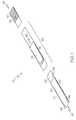
- FIG. 2illustrates an optional bobbin ( 60 ) for holding the instrument guide ( 10 ).
- the bobbin ( 60 )comprises a sheet of material foldable along a crease ( 62 ) that separates a base portion ( 61 ) and a cover portion ( 63 ).
- the bobbin ( 60 )has an opened position (as shown in the figure) and a closed position where the cover portion ( 63 ) is folded onto the base portion ( 63 ). In the closed position, the recesses ( 64 , 66 ) align with one another.
- the tab ( 68 )mates with the slot ( 69 ) to function as a fastener to selectively hold the bobbin ( 60 ) in the closed position.
- the bobbin ( 60 )is made from a single sheet of material, such as 0.01 inch LEXAN 8040. The sheet has a nominal width of about 3 inches and a nominal length of about 5 inches.
- the instrument guide ( 10 )is wrapped between the recesses ( 64 ) starting the with proximal end ( 24 ).
- the cover portion ( 63 )is closed and fastened, and the remainder of the instrument guide ( 10 ) is wrapped between the recesses ( 66 ).
- the medial pocket ( 40 )may be wrapped between recesses ( 64 ) in the opened position; however, the medial pocket could also be wrapped between recesses ( 66 ) in the closed position.
- the completely wrapped instrument guide ( 10 ) and bobbin ( 60 )may then be stored in a sterilized and sealed pouch with instructions.
- the surgeonunwraps a portion instrument guide ( 10 ) without releasing the tab ( 68 ).
- the surgeonmay work with the distal pocket ( 30 ) and a portion of the elongate flexible strip ( 20 ) while the remainder of the instrument guide ( 10 ) is contained in the closed bobbin ( 60 ) and out of the way during the surgery.
- the bobbin ( 60 )may be opened and the remainder of the instrument guide ( 10 ) unwrapped and used. The bobbin ( 60 ) may then be discarded.
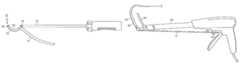
- FIGS. 3 and 4illustrates an example of a procedure to use the instrument guide ( 10 ) in conjunction with a treatment for atrial fibrillation.
- the positioning mechanism ( 70 ) in this exampleshown here as a dissector, is placed in the distal pocket ( 30 ).
- the positioning mechanism ( 70 )has an articulated shaft and includes an arcuate segment ( 72 ) that pivots about the joint ( 74 ).
- the arcuate segment ( 72 )has blunt and rounded distal end ( 76 ).
- a light sourceemits visible energy from the distal end ( 76 ) that facilitates, among other things, locating the distal end ( 76 ) during a procedure and differentiating tissue.
- the distal pocket ( 30 )is translucent.
- the followingdescribes an exemplary procedure using the positioning mechanism ( 70 ) to separate the left or right pair of pulmonary veins adjacent the left atrium.
- the proceduremay be performed during open or minimally invasive surgery.
- the distal end ( 76 ) of the arcuate segment ( 72 )is positioned adjacent the junction of one of the pulmonary veins (superior or inferior) and the left atrium.
- the distal end ( 76 )is advanced around the posterior of the pair of pulmonary veins while simultaneously pivoting the arcuate segment ( 72 ).
- the distal end ( 76 )continues to advance until it emerges beyond the other adjacent pulmonary vein (the inferior or superior, as the case may be).
- the advancement of the distal end ( 76 )separates the pair of pulmonary veins from the pericardial reflections, thus creating a dissected path between the pulmonary veins and the pericardium.
- the dissected pathmay be widened by sweeping the arcuate segment ( 72 ) and further separating the tissue and widening the dissected path.
- the surgeonmay grasp the distal end ( 22 ) of the instrument guide ( 10 ) and pull the distal pocket ( 30 ) from the arcuate segment ( 72 ).
- the arcuate segment ( 72 )may then be backed out and removed from the surgical field.
- the surgical instrument ( 80 ) in this exampleis a surgical clamp having a distal jaw ( 82 ) and a proximal jaw ( 84 ).
- the surgical instrument ( 80 )is used to ablate tissue with RF energy (one example is disclosed in U.S. Pat. No. 6,517,536).
- One of the jaws, in this example the distal jaw ( 82 )is placed in the medial pocket ( 40 ) of the instrument guide ( 10 ).
- the anchor ( 50 )attaches to surgical instrument ( 80 ) to prevent the distal jaw ( 82 ) from inadvertently liberating from the medial pocket ( 40 ).
- the anchor ( 50 )attaches to the clamp release lever ( 86 ) and the instrument guide ( 10 ) remains taut between the anchor ( 50 ) and medial pocket ( 40 ).
- the distal jaw ( 82 )may be accurately positioned in the dissected path until the pulmonary veins are interposed between the distal and proximal jaws ( 82 , 84 ).
- the anchor ( 50 )may then be detached.
- the medial pocket ( 40 )may be pulled from the distal jaw ( 82 ).
- the instrument guide ( 10 )may be removed from the surgical field.
- the instrument guide ( 10 )can remain in the surgical field to hold or lift the vessels like a sling.
- the distal and proximal jaws ( 82 , 84 )may then be positioned such that the tissue being treated is interposed between the jaws.
- the tissue being treatedis the atrium wall adjacent the pulmonary veins.
- the jawsmay then be closed and the tissue ablated.
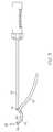
- FIG. 5illustrates another example of an instrument guide ( 90 ).
- the instrument guide ( 90 )has an elongate flexible body with a distal end ( 92 ) and a proximal end ( 94 ).
- the bodycomprises two or more portions. While geometry or and materials in the portions can vary, as shown here the distal portion is an elongate flexible strip ( 20 ) similar to instrument guide ( 10 ), and the proximal portion is an elongate flexible member ( 95 ) having a generally round cross-sectional geometry. While both portions are flexible, the proximal portion is more resilient than the distal portion.
- the flexible member ( 95 )has a generally round cross-sectional geometry (solid or tubular) and is formed from a flexible resilient material (such as rubber or durometer santoprene).
- the dimensions of the two portionscan vary, but in one embodiment, the proximal portion ( 95 ) is between about 6 and about 14 inches in length, and the distal portion ( 20 ) is between about 15 and about 20 inches in length.
- an anchor ( 97 )Located on or near the proximal end ( 94 ) is an anchor ( 97 ) adapted for attaching the guide ( 90 ) to a surgical instrument.
- the anchor ( 97 )is a male prong fastener dimensioned to engage a female fastener counterpart located on the surgical instrument ( 98 ).
- the guide ( 90 )can be separated from the surgical instrument by pulling the anchor ( 97 ) in the distal direction.
- a threshold pulling forceis required to prevent inadvertent separation.
- the anchor ( 97 )can be selectively engaged and disengaged from the surgical instrument.
- the anchormay be permanently attached to the surgical instrument.
- the anchor ( 97 )can take a variety of other forms other than the male/female arrangement described in this example, including without limitation screws or threads, snaps, adhesives, interference fits, barbs, magnets, and the like.
- the surgical instrument ( 98 )is the distal jaw of an ablation clamp; however, a variety of other surgical instruments could also be used depending on the surgical procedure and technique.
- the guide ( 90 )extends axially in-line with the jaw; however, the guide ( 90 ) could also extend at an angle from the jaw axis.
- the anchor ( 97 )could pivotally attach to the jaw, such as with a ball and socket joint.
- the followingillustrates one exemplary method for using the instrument guide ( 90 ). Similar to the example illustrated in FIG. 3 , a positioning mechanism is placed in the distal pocket ( 30 ). A dissection path is created between the pulmonary veins and the pericardium using the positioning mechanism. The surgeon may grasp the distal end ( 92 ) of the instrument guide ( 90 ) and pull the distal pocket ( 30 ) from the positioning mechanism. The positioning mechanism may then be backed out and removed from the surgical field. The anchor ( 97 ) is attached to the jaw ( 98 ), either before or after the dissected path is created.
- the distal jaw ( 98 )may be accurately positioned in the dissected path until the pulmonary veins are interposed between the distal and proximal jaws of the ablation clamp. With the anchor ( 97 ) attached to the jaw ( 98 ), the distal and proximal jaws may then be positioned such that the tissue being treated is interposed between the jaws. The jaws may then be closed and the tissue ablated. After treatment is concluded, the distal jaw ( 98 ) is backed out of the dissection path thus pulling the instrument guide ( 90 ) behind the jaw ( 98 ) until the instrument guide ( 90 ) is removed from the surgical field.
Landscapes
- Health & Medical Sciences (AREA)
- Life Sciences & Earth Sciences (AREA)
- Surgery (AREA)
- Heart & Thoracic Surgery (AREA)
- Engineering & Computer Science (AREA)
- Biomedical Technology (AREA)
- Nuclear Medicine, Radiotherapy & Molecular Imaging (AREA)
- Medical Informatics (AREA)
- Molecular Biology (AREA)
- Animal Behavior & Ethology (AREA)
- General Health & Medical Sciences (AREA)
- Public Health (AREA)
- Veterinary Medicine (AREA)
- Pathology (AREA)
- Surgical Instruments (AREA)
Abstract
Description
Claims (5)
Priority Applications (3)
| Application Number | Priority Date | Filing Date | Title |
|---|---|---|---|
| US11/254,057US8029528B2 (en) | 2005-01-03 | 2005-10-19 | Instrument guide and method for use |
| PCT/US2005/041668WO2006073582A2 (en) | 2005-01-03 | 2005-11-18 | Instrument guide and method for use |
| EP05851756AEP1853153A2 (en) | 2005-01-03 | 2005-11-18 | Instrument guide and method for use |
Applications Claiming Priority (2)
| Application Number | Priority Date | Filing Date | Title |
|---|---|---|---|
| US11/028,901US20060149121A1 (en) | 2005-01-03 | 2005-01-03 | Instrument guide and method for use |
| US11/254,057US8029528B2 (en) | 2005-01-03 | 2005-10-19 | Instrument guide and method for use |
Related Parent Applications (1)
| Application Number | Title | Priority Date | Filing Date |
|---|---|---|---|
| US11/028,901Continuation-In-PartUS20060149121A1 (en) | 2005-01-03 | 2005-01-03 | Instrument guide and method for use |
Publications (2)
| Publication Number | Publication Date |
|---|---|
| US20060167478A1 US20060167478A1 (en) | 2006-07-27 |
| US8029528B2true US8029528B2 (en) | 2011-10-04 |
Family
ID=35989559
Family Applications (1)
| Application Number | Title | Priority Date | Filing Date |
|---|---|---|---|
| US11/254,057Active2029-01-18US8029528B2 (en) | 2005-01-03 | 2005-10-19 | Instrument guide and method for use |
Country Status (3)
| Country | Link |
|---|---|
| US (1) | US8029528B2 (en) |
| EP (1) | EP1853153A2 (en) |
| WO (1) | WO2006073582A2 (en) |
Cited By (4)
| Publication number | Priority date | Publication date | Assignee | Title |
|---|---|---|---|---|
| JP6010244B1 (en)* | 2016-03-07 | 2016-10-19 | 富士システムズ株式会社 | Automatic suture instrument guide tube |
| US10357305B2 (en) | 2014-03-26 | 2019-07-23 | Venclose, Inc. | Venous disease treatment |
| US11678928B2 (en) | 2019-01-10 | 2023-06-20 | Atricure, Inc. | Surgical clamp |
| US12167882B2 (en) | 2021-09-17 | 2024-12-17 | Atricure, Inc. | Utilization of synergy EMR and EML to create a COXMAZE3 box lesion with radio frequency |
Families Citing this family (8)
| Publication number | Priority date | Publication date | Assignee | Title |
|---|---|---|---|---|
| US7288092B2 (en)* | 2003-04-23 | 2007-10-30 | Atricure, Inc. | Method and apparatus for ablating cardiac tissue with guide facility |
| US20060149121A1 (en)* | 2005-01-03 | 2006-07-06 | Hughett James D Sr | Instrument guide and method for use |
| US8029528B2 (en) | 2005-01-03 | 2011-10-04 | Atricure, Inc. | Instrument guide and method for use |
| WO2007089676A1 (en) | 2006-01-27 | 2007-08-09 | Medtronic, Inc. | Device and system for surgical dissection and or guidance of other medical devices into body |
| US8100899B2 (en) | 2007-11-12 | 2012-01-24 | Ihc Intellectual Asset Management, Llc | Combined endocardial and epicardial magnetically coupled ablation device |
| US8641710B2 (en) | 2007-11-12 | 2014-02-04 | Intermountain Invention Management, Llc | Magnetically coupling devices for mapping and/or ablating |
| FR2931655B1 (en)* | 2008-05-29 | 2010-06-25 | Cousin Biotech | ANCHORING AND GUIDING DEVICE, METHOD FOR MANUFACTURING SUCH DEVICE AND PROTHETIC IMPLANT EQUIPPED WITH SUCH A DEVICE |
| US9072518B2 (en) | 2011-05-31 | 2015-07-07 | Atricure, Inc. | High-voltage pulse ablation systems and methods |
Citations (68)
| Publication number | Priority date | Publication date | Assignee | Title |
|---|---|---|---|---|
| US2134152A (en) | 1937-01-06 | 1938-10-25 | Schwarzmayr Ludwig | Wound drain-strip |
| US3104077A (en) | 1960-10-25 | 1963-09-17 | Diamond National Corp | Collapsible paperboard spool |
| US3207421A (en) | 1962-12-14 | 1965-09-21 | Helen R Hunger | Reminder device |
| US3308940A (en) | 1965-08-11 | 1967-03-14 | Jr Theodore Morris | Clinical thermometer device |
| US3460742A (en) | 1968-01-29 | 1969-08-12 | Weck & Co Inc Edward | Peelable transparent envelope for sterile articles |
| US4887615A (en) | 1988-12-28 | 1989-12-19 | Microtek Medical Inc. | Sterile drape for ultrasound probe |
| US5033477A (en)* | 1987-11-13 | 1991-07-23 | Thomas J. Fogarty | Method and apparatus for providing intrapericardial access and inserting intrapericardial electrodes |
| US5071428A (en)* | 1989-09-08 | 1991-12-10 | Ventritex, Inc. | Method and apparatus for providing intrapericardial access and inserting intrapericardial electrodes |
| US5125928A (en)* | 1989-04-13 | 1992-06-30 | Everest Medical Corporation | Ablation catheter with selectively deployable electrodes |
| US5165425A (en)* | 1989-07-06 | 1992-11-24 | Dow Corning France S.A. | Method of forming a flap of tissue |
| US5176692A (en) | 1991-12-09 | 1993-01-05 | Wilk Peter J | Method and surgical instrument for repairing hernia |
| US5456720A (en) | 1991-02-08 | 1995-10-10 | Schultz; Leonard S. | Prosthesis for repair of direct space and indirect space inguinal hernias |
| US5487385A (en)* | 1993-12-03 | 1996-01-30 | Avitall; Boaz | Atrial mapping and ablation catheter system |
| US5500012A (en)* | 1992-07-15 | 1996-03-19 | Angeion Corporation | Ablation catheter system |
| WO1996031155A1 (en) | 1995-04-06 | 1996-10-10 | Guthrie Robert B | Methods and apparatus for inhibiting contamination of reusable pulse oximetry sensors |
| US5575766A (en)* | 1993-11-03 | 1996-11-19 | Daig Corporation | Process for the nonsurgical mapping and treatment of atrial arrhythmia using catheters guided by shaped guiding introducers |
| US5593441A (en) | 1992-03-04 | 1997-01-14 | C. R. Bard, Inc. | Method for limiting the incidence of postoperative adhesions |
| US5687924A (en) | 1994-05-17 | 1997-11-18 | Reiche; Kathryn Louise | Flexible plastic apparatus for storing embroidery floss |
| US5687896A (en) | 1996-02-26 | 1997-11-18 | Clift; Kelli A. | Personal article storage apparatus |
| US5718666A (en)* | 1996-02-29 | 1998-02-17 | Bioenterics Corporation | Transilluminating bougie |
| US5730127A (en)* | 1993-12-03 | 1998-03-24 | Avitall; Boaz | Mapping and ablation catheter system |
| US5740808A (en)* | 1996-10-28 | 1998-04-21 | Ep Technologies, Inc | Systems and methods for guilding diagnostic or therapeutic devices in interior tissue regions |
| US5766187A (en)* | 1995-10-11 | 1998-06-16 | Sugarbaker; David J. | Mechanism for guiding surgical instruments |
| US5785706A (en)* | 1996-11-18 | 1998-07-28 | Daig Corporation | Nonsurgical mapping and treatment of cardiac arrhythmia using a catheter contained within a guiding introducer containing openings |
| US5855590A (en)* | 1995-04-03 | 1999-01-05 | Heartport, Inc. | Clamp assembly and method of use |
| US5876398A (en)* | 1994-09-08 | 1999-03-02 | Medtronic, Inc. | Method and apparatus for R-F ablation |
| US5921924A (en)* | 1993-12-03 | 1999-07-13 | Avitall; Boaz | Mapping and ablation catheter system utilizing multiple control elements |
| US5922026A (en) | 1997-05-01 | 1999-07-13 | Origin Medsystems, Inc. | Surgical method and prosthetic strip therefor |
| US5971983A (en)* | 1997-05-09 | 1999-10-26 | The Regents Of The University Of California | Tissue ablation device and method of use |
| US6010531A (en)* | 1993-02-22 | 2000-01-04 | Heartport, Inc. | Less-invasive devices and methods for cardiac valve surgery |
| US6012457A (en)* | 1997-07-08 | 2000-01-11 | The Regents Of The University Of California | Device and method for forming a circumferential conduction block in a pulmonary vein |
| US6015382A (en)* | 1997-10-16 | 2000-01-18 | General Surgical Innovations, Inc. | Inflatable manipulator for organ positioning during surgery and method of use |
| US6024740A (en)* | 1997-07-08 | 2000-02-15 | The Regents Of The University Of California | Circumferential ablation device assembly |
| US6036670A (en)* | 1997-12-23 | 2000-03-14 | Cordis Corporation | Coiled transition balloon catheter, assembly and procedure |
| US6047218A (en)* | 1996-10-28 | 2000-04-04 | Ep Technologies, Inc. | Systems and methods for visualizing interior tissue regions |
| US6071281A (en)* | 1998-05-05 | 2000-06-06 | Ep Technologies, Inc. | Surgical method and apparatus for positioning a diagnostic or therapeutic element within the body and remote power control unit for use with same |
| US6080168A (en) | 1997-08-28 | 2000-06-27 | Levin; John M. | Compression pad for laparoscopic/thorascopic surgery |
| US6117101A (en)* | 1997-07-08 | 2000-09-12 | The Regents Of The University Of California | Circumferential ablation device assembly |
| US6123703A (en)* | 1998-09-19 | 2000-09-26 | Tu; Lily Chen | Ablation catheter and methods for treating tissues |
| US6142994A (en)* | 1994-10-07 | 2000-11-07 | Ep Technologies, Inc. | Surgical method and apparatus for positioning a diagnostic a therapeutic element within the body |
| WO2001021231A2 (en) | 1999-09-08 | 2001-03-29 | Joseph Grayzel | Percutaneous entry system and method |
| US6216931B1 (en) | 1999-07-22 | 2001-04-17 | Matthew Trawinski | Combined work-belt and tool storage system |
| US6224616B1 (en) | 1994-09-29 | 2001-05-01 | Bard Asdi Inc. | Hernia mesh patch |
| US6224543B1 (en) | 1998-05-21 | 2001-05-01 | Adroit Medical Systems, Inc. | Non-latex inverted sheath device |
| US6264087B1 (en)* | 1999-07-12 | 2001-07-24 | Powermed, Inc. | Expanding parallel jaw device for use with an electromechanical driver device |
| US6311692B1 (en)* | 1996-10-22 | 2001-11-06 | Epicor, Inc. | Apparatus and method for diagnosis and therapy of electrophysiological disease |
| US20020019629A1 (en)* | 1998-07-10 | 2002-02-14 | Medtronic, Inc. | Devices, systems and methods for transluminally and controllably forming intramyocardial channels in cardiac tissue |
| US20020082595A1 (en)* | 1998-03-02 | 2002-06-27 | Langberg Jonathan J. | Tissue ablation system and method for forming long linear lesion |
| US20020099364A1 (en)* | 1997-02-27 | 2002-07-25 | Cryocath Technologies, Inc. | Apparatus and method for performing a treatment on a selected tissue region |
| US20020115990A1 (en)* | 2001-01-31 | 2002-08-22 | Acker David E. | Pulmonary vein ablation with myocardial tissue locating |
| US20020120263A1 (en)* | 2000-12-15 | 2002-08-29 | Tony R. Brown | Atrial fibrillation RF treatment device and method |
| US6447507B1 (en)* | 1997-11-12 | 2002-09-10 | Daig Corporation | Rail catheter ablation and mapping system |
| US20020156488A1 (en) | 2001-03-09 | 2002-10-24 | Gellman Barry N. | System for implanting an implant and method thereof |
| US20020183738A1 (en)* | 1999-06-02 | 2002-12-05 | Chee U. Hiram | Method and apparatus for treatment of atrial fibrillation |
| US20030060822A1 (en)* | 1998-05-06 | 2003-03-27 | Schaer Alan K. | Irrigated ablation device assembly |
| US20030078574A1 (en)* | 2000-04-25 | 2003-04-24 | Hall Jeffrey A. | Ablation catheter, system, and method of use thereof |
| US20030093104A1 (en)* | 1999-10-29 | 2003-05-15 | Bonner Matthew D. | Methods and apparatus for providing intra-pericardial access |
| US20030125726A1 (en)* | 1997-07-08 | 2003-07-03 | Maguire Mark A. | Tissue ablation device assembly and method for electrically isolating a pulmonary vein ostium from an atrial wall |
| US20030125729A1 (en)* | 2000-04-27 | 2003-07-03 | Hooven Michael D. | Transmural ablation device |
| US20030130598A1 (en)* | 2002-01-07 | 2003-07-10 | Cardiac Pacemaker, Inc. | Steerable guide catheter with pre-shaped rotatable shaft |
| US20030144657A1 (en)* | 2002-01-28 | 2003-07-31 | Cardiac Pacemakers, Inc. | Inner and outer telescoping catheter delivery system |
| US20030149440A1 (en) | 1999-06-09 | 2003-08-07 | Ethicon, Inc. | Surgical instrument and method for treating female urinary incontinence |
| US20030176762A1 (en) | 2000-03-09 | 2003-09-18 | Kammerer Gene W. | Surgical instrument and method for treating organ prolapse conditions |
| US20040216748A1 (en) | 1999-08-10 | 2004-11-04 | Chin Albert K. | Apparatus and method for endoscopic encirclement of pulmonary veins for epicardial ablation |
| US20040249368A1 (en) | 2003-04-23 | 2004-12-09 | Hooven Michael D. | Method and apparatus for ablating cardiac tissue with guide facility |
| US20060149121A1 (en) | 2005-01-03 | 2006-07-06 | Hughett James D Sr | Instrument guide and method for use |
| US20060167478A1 (en) | 2005-01-03 | 2006-07-27 | Miller Kenneth L | Instrument guide and method for use |
| US7101381B2 (en) | 2002-08-02 | 2006-09-05 | C.R. Bard, Inc. | Implantable prosthesis |
Family Cites Families (1)
| Publication number | Priority date | Publication date | Assignee | Title |
|---|---|---|---|---|
| US6393052B2 (en)* | 2000-02-17 | 2002-05-21 | At&T Corporation | Method and apparatus for minimizing near end cross talk due to discrete multi-tone transmission in cable binders |
- 2005
- 2005-10-19USUS11/254,057patent/US8029528B2/enactiveActive
- 2005-11-18EPEP05851756Apatent/EP1853153A2/ennot_activeWithdrawn
- 2005-11-18WOPCT/US2005/041668patent/WO2006073582A2/enactiveApplication Filing
Patent Citations (78)
| Publication number | Priority date | Publication date | Assignee | Title |
|---|---|---|---|---|
| US2134152A (en) | 1937-01-06 | 1938-10-25 | Schwarzmayr Ludwig | Wound drain-strip |
| US3104077A (en) | 1960-10-25 | 1963-09-17 | Diamond National Corp | Collapsible paperboard spool |
| US3207421A (en) | 1962-12-14 | 1965-09-21 | Helen R Hunger | Reminder device |
| US3308940A (en) | 1965-08-11 | 1967-03-14 | Jr Theodore Morris | Clinical thermometer device |
| US3460742A (en) | 1968-01-29 | 1969-08-12 | Weck & Co Inc Edward | Peelable transparent envelope for sterile articles |
| US5033477A (en)* | 1987-11-13 | 1991-07-23 | Thomas J. Fogarty | Method and apparatus for providing intrapericardial access and inserting intrapericardial electrodes |
| US4887615A (en) | 1988-12-28 | 1989-12-19 | Microtek Medical Inc. | Sterile drape for ultrasound probe |
| US5125928A (en)* | 1989-04-13 | 1992-06-30 | Everest Medical Corporation | Ablation catheter with selectively deployable electrodes |
| US5165425A (en)* | 1989-07-06 | 1992-11-24 | Dow Corning France S.A. | Method of forming a flap of tissue |
| US5071428A (en)* | 1989-09-08 | 1991-12-10 | Ventritex, Inc. | Method and apparatus for providing intrapericardial access and inserting intrapericardial electrodes |
| US5456720A (en) | 1991-02-08 | 1995-10-10 | Schultz; Leonard S. | Prosthesis for repair of direct space and indirect space inguinal hernias |
| US5176692A (en) | 1991-12-09 | 1993-01-05 | Wilk Peter J | Method and surgical instrument for repairing hernia |
| US5593441A (en) | 1992-03-04 | 1997-01-14 | C. R. Bard, Inc. | Method for limiting the incidence of postoperative adhesions |
| US5500012A (en)* | 1992-07-15 | 1996-03-19 | Angeion Corporation | Ablation catheter system |
| US6010531A (en)* | 1993-02-22 | 2000-01-04 | Heartport, Inc. | Less-invasive devices and methods for cardiac valve surgery |
| US5814028A (en)* | 1993-11-03 | 1998-09-29 | Daig Corporation | Curved guiding introducers for cardiac access |
| US5575766A (en)* | 1993-11-03 | 1996-11-19 | Daig Corporation | Process for the nonsurgical mapping and treatment of atrial arrhythmia using catheters guided by shaped guiding introducers |
| US5487385A (en)* | 1993-12-03 | 1996-01-30 | Avitall; Boaz | Atrial mapping and ablation catheter system |
| US20020002329A1 (en)* | 1993-12-03 | 2002-01-03 | Boaz Avitall | Mapping and ablation catheter system |
| US5730127A (en)* | 1993-12-03 | 1998-03-24 | Avitall; Boaz | Mapping and ablation catheter system |
| US5921924A (en)* | 1993-12-03 | 1999-07-13 | Avitall; Boaz | Mapping and ablation catheter system utilizing multiple control elements |
| US5842984A (en)* | 1993-12-03 | 1998-12-01 | Avitall; Boaz | Mapping and ablation catheter system with locking mechanism |
| US5687924A (en) | 1994-05-17 | 1997-11-18 | Reiche; Kathryn Louise | Flexible plastic apparatus for storing embroidery floss |
| US5876398A (en)* | 1994-09-08 | 1999-03-02 | Medtronic, Inc. | Method and apparatus for R-F ablation |
| US6224616B1 (en) | 1994-09-29 | 2001-05-01 | Bard Asdi Inc. | Hernia mesh patch |
| US6142994A (en)* | 1994-10-07 | 2000-11-07 | Ep Technologies, Inc. | Surgical method and apparatus for positioning a diagnostic a therapeutic element within the body |
| US5855590A (en)* | 1995-04-03 | 1999-01-05 | Heartport, Inc. | Clamp assembly and method of use |
| WO1996031155A1 (en) | 1995-04-06 | 1996-10-10 | Guthrie Robert B | Methods and apparatus for inhibiting contamination of reusable pulse oximetry sensors |
| US5766187A (en)* | 1995-10-11 | 1998-06-16 | Sugarbaker; David J. | Mechanism for guiding surgical instruments |
| US5687896A (en) | 1996-02-26 | 1997-11-18 | Clift; Kelli A. | Personal article storage apparatus |
| US5718666A (en)* | 1996-02-29 | 1998-02-17 | Bioenterics Corporation | Transilluminating bougie |
| US20030028187A1 (en)* | 1996-10-22 | 2003-02-06 | Epicor, Inc. | Device and method for forming a lesion |
| US6314962B1 (en)* | 1996-10-22 | 2001-11-13 | Epicor, Inc. | Method of ablating tissue around the pulmonary veins |
| US6314963B1 (en)* | 1996-10-22 | 2001-11-13 | Epicor, Inc. | Method of ablating tissue from an epicardial location |
| US6474340B1 (en)* | 1996-10-22 | 2002-11-05 | Epicor, Inc. | Apparatus and method for diagnosis and therapy of electrophysiological disease |
| US20030069577A1 (en)* | 1996-10-22 | 2003-04-10 | Epicor, Inc. | Apparatus and method for diagnosis and therapy of electrophysiological disease |
| US6311692B1 (en)* | 1996-10-22 | 2001-11-06 | Epicor, Inc. | Apparatus and method for diagnosis and therapy of electrophysiological disease |
| US5740808A (en)* | 1996-10-28 | 1998-04-21 | Ep Technologies, Inc | Systems and methods for guilding diagnostic or therapeutic devices in interior tissue regions |
| US6047218A (en)* | 1996-10-28 | 2000-04-04 | Ep Technologies, Inc. | Systems and methods for visualizing interior tissue regions |
| US5785706A (en)* | 1996-11-18 | 1998-07-28 | Daig Corporation | Nonsurgical mapping and treatment of cardiac arrhythmia using a catheter contained within a guiding introducer containing openings |
| US20020099364A1 (en)* | 1997-02-27 | 2002-07-25 | Cryocath Technologies, Inc. | Apparatus and method for performing a treatment on a selected tissue region |
| US5922026A (en) | 1997-05-01 | 1999-07-13 | Origin Medsystems, Inc. | Surgical method and prosthetic strip therefor |
| US5971983A (en)* | 1997-05-09 | 1999-10-26 | The Regents Of The University Of California | Tissue ablation device and method of use |
| US6117101A (en)* | 1997-07-08 | 2000-09-12 | The Regents Of The University Of California | Circumferential ablation device assembly |
| US6024740A (en)* | 1997-07-08 | 2000-02-15 | The Regents Of The University Of California | Circumferential ablation device assembly |
| US20030125726A1 (en)* | 1997-07-08 | 2003-07-03 | Maguire Mark A. | Tissue ablation device assembly and method for electrically isolating a pulmonary vein ostium from an atrial wall |
| US6012457A (en)* | 1997-07-08 | 2000-01-11 | The Regents Of The University Of California | Device and method for forming a circumferential conduction block in a pulmonary vein |
| US6080168A (en) | 1997-08-28 | 2000-06-27 | Levin; John M. | Compression pad for laparoscopic/thorascopic surgery |
| US6015382A (en)* | 1997-10-16 | 2000-01-18 | General Surgical Innovations, Inc. | Inflatable manipulator for organ positioning during surgery and method of use |
| US6447507B1 (en)* | 1997-11-12 | 2002-09-10 | Daig Corporation | Rail catheter ablation and mapping system |
| US6036670A (en)* | 1997-12-23 | 2000-03-14 | Cordis Corporation | Coiled transition balloon catheter, assembly and procedure |
| US20020082595A1 (en)* | 1998-03-02 | 2002-06-27 | Langberg Jonathan J. | Tissue ablation system and method for forming long linear lesion |
| US20030135207A1 (en)* | 1998-03-02 | 2003-07-17 | Langberg Jonathan J. | Tissue ablation system and method for forming long linear lesion |
| US6071281A (en)* | 1998-05-05 | 2000-06-06 | Ep Technologies, Inc. | Surgical method and apparatus for positioning a diagnostic or therapeutic element within the body and remote power control unit for use with same |
| US20030060822A1 (en)* | 1998-05-06 | 2003-03-27 | Schaer Alan K. | Irrigated ablation device assembly |
| US6224543B1 (en) | 1998-05-21 | 2001-05-01 | Adroit Medical Systems, Inc. | Non-latex inverted sheath device |
| US20020019629A1 (en)* | 1998-07-10 | 2002-02-14 | Medtronic, Inc. | Devices, systems and methods for transluminally and controllably forming intramyocardial channels in cardiac tissue |
| US6123703A (en)* | 1998-09-19 | 2000-09-26 | Tu; Lily Chen | Ablation catheter and methods for treating tissues |
| US20020183738A1 (en)* | 1999-06-02 | 2002-12-05 | Chee U. Hiram | Method and apparatus for treatment of atrial fibrillation |
| US20030149440A1 (en) | 1999-06-09 | 2003-08-07 | Ethicon, Inc. | Surgical instrument and method for treating female urinary incontinence |
| US6264087B1 (en)* | 1999-07-12 | 2001-07-24 | Powermed, Inc. | Expanding parallel jaw device for use with an electromechanical driver device |
| US6216931B1 (en) | 1999-07-22 | 2001-04-17 | Matthew Trawinski | Combined work-belt and tool storage system |
| US20040216748A1 (en) | 1999-08-10 | 2004-11-04 | Chin Albert K. | Apparatus and method for endoscopic encirclement of pulmonary veins for epicardial ablation |
| WO2001021231A2 (en) | 1999-09-08 | 2001-03-29 | Joseph Grayzel | Percutaneous entry system and method |
| US20030093104A1 (en)* | 1999-10-29 | 2003-05-15 | Bonner Matthew D. | Methods and apparatus for providing intra-pericardial access |
| US20030176762A1 (en) | 2000-03-09 | 2003-09-18 | Kammerer Gene W. | Surgical instrument and method for treating organ prolapse conditions |
| US20030078574A1 (en)* | 2000-04-25 | 2003-04-24 | Hall Jeffrey A. | Ablation catheter, system, and method of use thereof |
| US20030125729A1 (en)* | 2000-04-27 | 2003-07-03 | Hooven Michael D. | Transmural ablation device |
| US20020120263A1 (en)* | 2000-12-15 | 2002-08-29 | Tony R. Brown | Atrial fibrillation RF treatment device and method |
| US20020115990A1 (en)* | 2001-01-31 | 2002-08-22 | Acker David E. | Pulmonary vein ablation with myocardial tissue locating |
| US20020156488A1 (en) | 2001-03-09 | 2002-10-24 | Gellman Barry N. | System for implanting an implant and method thereof |
| US6936052B2 (en) | 2001-03-09 | 2005-08-30 | Boston Scientific Scimed, Inc. | System for implanting an implant and method thereof |
| US20030130598A1 (en)* | 2002-01-07 | 2003-07-10 | Cardiac Pacemaker, Inc. | Steerable guide catheter with pre-shaped rotatable shaft |
| US20030144657A1 (en)* | 2002-01-28 | 2003-07-31 | Cardiac Pacemakers, Inc. | Inner and outer telescoping catheter delivery system |
| US7101381B2 (en) | 2002-08-02 | 2006-09-05 | C.R. Bard, Inc. | Implantable prosthesis |
| US20040249368A1 (en) | 2003-04-23 | 2004-12-09 | Hooven Michael D. | Method and apparatus for ablating cardiac tissue with guide facility |
| US20060149121A1 (en) | 2005-01-03 | 2006-07-06 | Hughett James D Sr | Instrument guide and method for use |
| US20060167478A1 (en) | 2005-01-03 | 2006-07-27 | Miller Kenneth L | Instrument guide and method for use |
Non-Patent Citations (6)
| Title |
|---|
| Balkhy, et al., Minimally invasive atrial fibrillation ablation combined with a new technique for thoracoscopic stapling of the left atrial appendage: case report, Heart Surgery Forum, vol. 7(6), 2004, pp. 353-355. |
| Mehall et al., "Bilateral Vats Pulmonary Vein Isolation, Left Atrial Appendage . . ." CTSNet, www.ctsnet.org/sections/clinicalresources/adultcardiac/expert-tech-22.html, Mar. 16, 2007. |
| Mehall et al., "Bilateral Vats Pulmonary Vein Isolation, Left Atrial Appendage . . ." CTSNet, www.ctsnet.org/sections/clinicalresources/adultcardiac/expert—tech-22.html, Mar. 16, 2007. |
| Office Action dated May 16, 2007, issued in U.S. Appl. No. 11/028,901. |
| Pellethane Thermoplastic Polyurethane Elastomers, Dow Engineering Plastics, www.dow.com/engineeringplastics/prod/na/pel.htm p. 1 and 2, Oct. 29, 2004. |
| The Dow Chemical Company, Typical Physical Properties of Pellethane, 9 pages, Printed in U.S.A., Aug. 2001. |
Cited By (6)
| Publication number | Priority date | Publication date | Assignee | Title |
|---|---|---|---|---|
| US10357305B2 (en) | 2014-03-26 | 2019-07-23 | Venclose, Inc. | Venous disease treatment |
| US11877784B2 (en) | 2014-03-26 | 2024-01-23 | Venclose, Inc. | Venous disease treatment |
| US12396778B2 (en) | 2014-03-26 | 2025-08-26 | Venclose, Inc. | Venous disease treatment |
| JP6010244B1 (en)* | 2016-03-07 | 2016-10-19 | 富士システムズ株式会社 | Automatic suture instrument guide tube |
| US11678928B2 (en) | 2019-01-10 | 2023-06-20 | Atricure, Inc. | Surgical clamp |
| US12167882B2 (en) | 2021-09-17 | 2024-12-17 | Atricure, Inc. | Utilization of synergy EMR and EML to create a COXMAZE3 box lesion with radio frequency |
Also Published As
| Publication number | Publication date |
|---|---|
| WO2006073582A3 (en) | 2006-12-21 |
| EP1853153A2 (en) | 2007-11-14 |
| US20060167478A1 (en) | 2006-07-27 |
| WO2006073582A2 (en) | 2006-07-13 |
Similar Documents
| Publication | Publication Date | Title |
|---|---|---|
| US20240074778A1 (en) | Multi-functional medical device and related methods of use | |
| EP2659842B1 (en) | Surgical clip applier with dissector | |
| ES2612108T3 (en) | Sample recovery device that includes an integrated slide handle | |
| US8029528B2 (en) | Instrument guide and method for use | |
| CN108392239A (en) | Become the connector clamp that guide is fastened to surgical fasteners application devices | |
| CA2722645A1 (en) | Orifice introducer device | |
| JP2015144807A (en) | Introducer assembly for surgical fastener applying apparatus | |
| US20120226287A1 (en) | Endoscopic devices for tissue removal or repair and associated methods | |
| MX2013012439A (en) | Advance suture passer. | |
| US20070144537A1 (en) | Instrument guide and method for use | |
| JP4320207B2 (en) | Endoscopic resection aid | |
| CN115397341B (en) | Systems and apparatus for processing tissue | |
| US12349919B2 (en) | Systems for endoscopic submucosal dissection | |
| US20250072900A1 (en) | Body lumen wall invagination | |
| US12232768B2 (en) | Cannula for preventing tumor seeding | |
| US12016526B2 (en) | Mucous membrane lifting instrument and mucous membrane lifting method | |
| JP2020000629A (en) | Endoscope treatment auxiliary tool | |
| JP6010244B1 (en) | Automatic suture instrument guide tube | |
| KR20160019159A (en) | Laparoscopic cutting for laparoscopic surgery | |
| CN119214706A (en) | A tissue closure device | |
| JP2006095336A (en) | Treating instrument for cutting living body tissue |
Legal Events
| Date | Code | Title | Description |
|---|---|---|---|
| AS | Assignment | Owner name:ATRICURE, INC., OHIO Free format text:ASSIGNMENT OF ASSIGNORS INTEREST;ASSIGNORS:PRIVITERA, SALVATORE;HUGHETT, JAMES DAVID, SR.;MILLER, KENNETH LANCE;SIGNING DATES FROM 20051201 TO 20051202;REEL/FRAME:017128/0575 Owner name:ATRICURE, INC., OHIO Free format text:ASSIGNMENT OF ASSIGNORS INTEREST;ASSIGNORS:PRIVITERA, SALVATORE;HUGHETT, JAMES DAVID, SR.;MILLER, KENNETH LANCE;REEL/FRAME:017128/0575;SIGNING DATES FROM 20051201 TO 20051202 | |
| STCF | Information on status: patent grant | Free format text:PATENTED CASE | |
| AS | Assignment | Owner name:SILICON VALLEY BANK, COLORADO Free format text:SECURITY INTEREST;ASSIGNORS:ATRICURE, INC.;ATRICURE, LLC;ENDOSCOPIC TECHNOLOGIES, LLC;REEL/FRAME:032812/0032 Effective date:20140424 | |
| REMI | Maintenance fee reminder mailed | ||
| FPAY | Fee payment | Year of fee payment:4 | |
| SULP | Surcharge for late payment | ||
| FEPP | Fee payment procedure | Free format text:PAT HOLDER NO LONGER CLAIMS SMALL ENTITY STATUS, ENTITY STATUS SET TO UNDISCOUNTED (ORIGINAL EVENT CODE: STOL); ENTITY STATUS OF PATENT OWNER: LARGE ENTITY | |
| AS | Assignment | Owner name:SILICON VALLEY BANK, CALIFORNIA Free format text:SECOND AMENDED AND RESTATED JOINT INTELLECTUAL PROPERTY SECURITY AGREEMENT;ASSIGNORS:ATRICURE, INC.;ATRICURE, LLC;ENDOSCOPIC TECHNOLOGIES, LLC;AND OTHERS;REEL/FRAME:038520/0062 Effective date:20160425 | |
| AS | Assignment | Owner name:SILICON VALLEY BANK, CALIFORNIA Free format text:SECURITY INTEREST;ASSIGNORS:ATRICURE, INC.;ATRICURE, LLC;ENDOSCOPIC TECHNOLOGIES, LLC;AND OTHERS;REEL/FRAME:047951/0496 Effective date:20180223 | |
| FEPP | Fee payment procedure | Free format text:7.5 YR SURCHARGE - LATE PMT W/IN 6 MO, LARGE ENTITY (ORIGINAL EVENT CODE: M1555); ENTITY STATUS OF PATENT OWNER: LARGE ENTITY | |
| MAFP | Maintenance fee payment | Free format text:PAYMENT OF MAINTENANCE FEE, 8TH YEAR, LARGE ENTITY (ORIGINAL EVENT CODE: M1552); ENTITY STATUS OF PATENT OWNER: LARGE ENTITY Year of fee payment:8 | |
| MAFP | Maintenance fee payment | Free format text:PAYMENT OF MAINTENANCE FEE, 12TH YEAR, LARGE ENTITY (ORIGINAL EVENT CODE: M1553); ENTITY STATUS OF PATENT OWNER: LARGE ENTITY Year of fee payment:12 | |
| AS | Assignment | Owner name:SENTREHEART LLC, OHIO Free format text:RELEASE BY SECURED PARTY;ASSIGNOR:SILICON VALLEY BANK, A DIVISION OF FIRST-CITIZENS BANK & TRUST COMPANY;REEL/FRAME:066256/0797 Effective date:20240105 Owner name:NCONTACT SURGICAL, LLC, OHIO Free format text:RELEASE BY SECURED PARTY;ASSIGNOR:SILICON VALLEY BANK, A DIVISION OF FIRST-CITIZENS BANK & TRUST COMPANY;REEL/FRAME:066256/0797 Effective date:20240105 Owner name:ENDOSCOPIC TECHNOLOGIES, LLC, OHIO Free format text:RELEASE BY SECURED PARTY;ASSIGNOR:SILICON VALLEY BANK, A DIVISION OF FIRST-CITIZENS BANK & TRUST COMPANY;REEL/FRAME:066256/0797 Effective date:20240105 Owner name:ATRICURE, LLC, OHIO Free format text:RELEASE BY SECURED PARTY;ASSIGNOR:SILICON VALLEY BANK, A DIVISION OF FIRST-CITIZENS BANK & TRUST COMPANY;REEL/FRAME:066256/0797 Effective date:20240105 Owner name:ATRICURE, INC., OHIO Free format text:RELEASE BY SECURED PARTY;ASSIGNOR:SILICON VALLEY BANK, A DIVISION OF FIRST-CITIZENS BANK & TRUST COMPANY;REEL/FRAME:066256/0797 Effective date:20240105 Owner name:JPMORGAN CHASE BANK, N.A., AS ADMINISTRATIVE AGENT, ILLINOIS Free format text:SECURITY INTEREST;ASSIGNORS:ATRICURE, INC.;ATRICURE, LLC.;REEL/FRAME:066267/0896 Effective date:20240105 |