US8029510B2 - Surgical machine and method for controlling and/or regulating a surgical machine - Google Patents
Surgical machine and method for controlling and/or regulating a surgical machineDownload PDFInfo
- Publication number
- US8029510B2 US8029510B2US11/974,182US97418207AUS8029510B2US 8029510 B2US8029510 B2US 8029510B2US 97418207 AUS97418207 AUS 97418207AUS 8029510 B2US8029510 B2US 8029510B2
- Authority
- US
- United States
- Prior art keywords
- machine
- motor
- accordance
- actuating
- housing
- Prior art date
- Legal status (The legal status is an assumption and is not a legal conclusion. Google has not performed a legal analysis and makes no representation as to the accuracy of the status listed.)
- Active, expires
Links
- 238000000034methodMethods0.000titleabstractdescription42
- 230000001105regulatory effectEffects0.000titleabstractdescription33
- 230000001276controlling effectEffects0.000titleabstractdescription32
- XEEYBQQBJWHFJM-UHFFFAOYSA-NIronChemical compound[Fe]XEEYBQQBJWHFJM-UHFFFAOYSA-N0.000claimsdescription40
- 230000005291magnetic effectEffects0.000claimsdescription19
- 230000008859changeEffects0.000claimsdescription11
- 230000005294ferromagnetic effectEffects0.000claimsdescription3
- 230000005290antiferromagnetic effectEffects0.000claimsdescription2
- 230000002596correlated effectEffects0.000claimsdescription2
- 230000005292diamagnetic effectEffects0.000claimsdescription2
- 230000005293ferrimagnetic effectEffects0.000claimsdescription2
- 230000005298paramagnetic effectEffects0.000claimsdescription2
- 230000004044responseEffects0.000claimsdescription2
- 238000012423maintenanceMethods0.000abstractdescription12
- 230000008878couplingEffects0.000description128
- 238000010168coupling processMethods0.000description128
- 238000005859coupling reactionMethods0.000description128
- 238000004804windingMethods0.000description63
- 238000013461designMethods0.000description38
- 230000003534oscillatory effectEffects0.000description34
- 230000000875corresponding effectEffects0.000description18
- 230000004888barrier functionEffects0.000description16
- 238000004140cleaningMethods0.000description15
- 230000007797corrosionEffects0.000description12
- 238000005260corrosionMethods0.000description12
- 238000001514detection methodMethods0.000description12
- 238000003780insertionMethods0.000description12
- 230000037431insertionEffects0.000description12
- 230000001954sterilising effectEffects0.000description12
- 230000000712assemblyEffects0.000description11
- 238000000429assemblyMethods0.000description11
- 238000010276constructionMethods0.000description11
- 230000001965increasing effectEffects0.000description11
- 230000003213activating effectEffects0.000description10
- 230000008901benefitEffects0.000description10
- 238000004659sterilization and disinfectionMethods0.000description10
- 229910052742ironInorganic materials0.000description9
- 230000007704transitionEffects0.000description9
- 230000004913activationEffects0.000description8
- 238000005553drillingMethods0.000description7
- 230000004907fluxEffects0.000description7
- 230000001976improved effectEffects0.000description6
- 230000009467reductionEffects0.000description6
- 238000007789sealingMethods0.000description6
- 230000001052transient effectEffects0.000description6
- 244000052616bacterial pathogenSpecies0.000description5
- 238000005266castingMethods0.000description5
- 239000000463materialSubstances0.000description5
- 238000003801millingMethods0.000description5
- 238000001356surgical procedureMethods0.000description5
- 208000027418Wounds and injuryDiseases0.000description4
- 238000005520cutting processMethods0.000description3
- 230000006378damageEffects0.000description3
- 238000013016dampingMethods0.000description3
- 230000007547defectEffects0.000description3
- 230000000694effectsEffects0.000description3
- 238000005516engineering processMethods0.000description3
- 230000006870functionEffects0.000description3
- 229910001416lithium ionInorganic materials0.000description3
- 239000007787solidSubstances0.000description3
- 238000012546transferMethods0.000description3
- 229910005813NiMHInorganic materials0.000description2
- QJVKUMXDEUEQLH-UHFFFAOYSA-N[B].[Fe].[Nd]Chemical compound[B].[Fe].[Nd]QJVKUMXDEUEQLH-UHFFFAOYSA-N0.000description2
- 239000000919ceramicSubstances0.000description2
- 230000002950deficientEffects0.000description2
- 238000010586diagramMethods0.000description2
- 239000000696magnetic materialSubstances0.000description2
- 238000004519manufacturing processMethods0.000description2
- 238000005259measurementMethods0.000description2
- 230000007246mechanismEffects0.000description2
- 229910001172neodymium magnetInorganic materials0.000description2
- 230000000149penetrating effectEffects0.000description2
- 125000006850spacer groupChemical group0.000description2
- 238000005406washingMethods0.000description2
- QNRATNLHPGXHMA-XZHTYLCXSA-N(r)-(6-ethoxyquinolin-4-yl)-[(2s,4s,5r)-5-ethyl-1-azabicyclo[2.2.2]octan-2-yl]methanol;hydrochlorideChemical compoundCl.C([C@H]([C@H](C1)CC)C2)CN1[C@@H]2[C@H](O)C1=CC=NC2=CC=C(OCC)C=C21QNRATNLHPGXHMA-XZHTYLCXSA-N0.000description1
- WHXSMMKQMYFTQS-UHFFFAOYSA-NLithiumChemical compound[Li]WHXSMMKQMYFTQS-UHFFFAOYSA-N0.000description1
- HBBGRARXTFLTSG-UHFFFAOYSA-NLithium ionChemical compound[Li+]HBBGRARXTFLTSG-UHFFFAOYSA-N0.000description1
- PWHULOQIROXLJO-UHFFFAOYSA-NManganeseChemical compound[Mn]PWHULOQIROXLJO-UHFFFAOYSA-N0.000description1
- 229910005580NiCdInorganic materials0.000description1
- 208000003028StutteringDiseases0.000description1
- RTAQQCXQSZGOHL-UHFFFAOYSA-NTitaniumChemical compound[Ti]RTAQQCXQSZGOHL-UHFFFAOYSA-N0.000description1
- 230000003321amplificationEffects0.000description1
- 230000033228biological regulationEffects0.000description1
- 230000015572biosynthetic processEffects0.000description1
- 239000012459cleaning agentSubstances0.000description1
- 238000004891communicationMethods0.000description1
- 239000012141concentrateSubstances0.000description1
- 230000007423decreaseEffects0.000description1
- 230000001419dependent effectEffects0.000description1
- 238000006073displacement reactionMethods0.000description1
- 230000005684electric fieldEffects0.000description1
- 230000007613environmental effectEffects0.000description1
- 239000003822epoxy resinSubstances0.000description1
- 239000000945fillerSubstances0.000description1
- 239000000446fuelSubstances0.000description1
- 230000006698inductionEffects0.000description1
- 230000001939inductive effectEffects0.000description1
- 208000014674injuryDiseases0.000description1
- 229910052744lithiumInorganic materials0.000description1
- 238000005461lubricationMethods0.000description1
- 238000003754machiningMethods0.000description1
- 229910052748manganeseInorganic materials0.000description1
- 239000011572manganeseSubstances0.000description1
- 239000012528membraneSubstances0.000description1
- 238000012544monitoring processMethods0.000description1
- 238000003199nucleic acid amplification methodMethods0.000description1
- 230000003287optical effectEffects0.000description1
- 230000010355oscillationEffects0.000description1
- 239000004033plasticSubstances0.000description1
- 229920000647polyepoxidePolymers0.000description1
- 229920000642polymerPolymers0.000description1
- 230000002028prematureEffects0.000description1
- 238000002360preparation methodMethods0.000description1
- 230000002035prolonged effectEffects0.000description1
- 230000001681protective effectEffects0.000description1
- 230000008439repair processEffects0.000description1
- 230000035945sensitivityEffects0.000description1
- 238000004904shorteningMethods0.000description1
- 239000000126substanceSubstances0.000description1
- 230000008093supporting effectEffects0.000description1
- 238000012360testing methodMethods0.000description1
- 230000036962time dependentEffects0.000description1
- 239000010936titaniumSubstances0.000description1
- 229910052719titaniumInorganic materials0.000description1
Images


Classifications
- A—HUMAN NECESSITIES
- A61—MEDICAL OR VETERINARY SCIENCE; HYGIENE
- A61B—DIAGNOSIS; SURGERY; IDENTIFICATION
- A61B17/00—Surgical instruments, devices or methods
- A61B17/16—Instruments for performing osteoclasis; Drills or chisels for bones; Trepans
- A61B17/1613—Component parts
- A—HUMAN NECESSITIES
- A61—MEDICAL OR VETERINARY SCIENCE; HYGIENE
- A61B—DIAGNOSIS; SURGERY; IDENTIFICATION
- A61B17/00—Surgical instruments, devices or methods
- A61B17/16—Instruments for performing osteoclasis; Drills or chisels for bones; Trepans
- A61B17/1613—Component parts
- A61B17/1626—Control means; Display units
- A—HUMAN NECESSITIES
- A61—MEDICAL OR VETERINARY SCIENCE; HYGIENE
- A61B—DIAGNOSIS; SURGERY; IDENTIFICATION
- A61B17/00—Surgical instruments, devices or methods
- A61B17/16—Instruments for performing osteoclasis; Drills or chisels for bones; Trepans
- A61B17/1613—Component parts
- A61B17/1628—Motors; Power supplies
- A—HUMAN NECESSITIES
- A61—MEDICAL OR VETERINARY SCIENCE; HYGIENE
- A61B—DIAGNOSIS; SURGERY; IDENTIFICATION
- A61B90/00—Instruments, implements or accessories specially adapted for surgery or diagnosis and not covered by any of the groups A61B1/00 - A61B50/00, e.g. for luxation treatment or for protecting wound edges
- A61B90/08—Accessories or related features not otherwise provided for
- A61B2090/0813—Accessories designed for easy sterilising, i.e. re-usable
- Y—GENERAL TAGGING OF NEW TECHNOLOGICAL DEVELOPMENTS; GENERAL TAGGING OF CROSS-SECTIONAL TECHNOLOGIES SPANNING OVER SEVERAL SECTIONS OF THE IPC; TECHNICAL SUBJECTS COVERED BY FORMER USPC CROSS-REFERENCE ART COLLECTIONS [XRACs] AND DIGESTS
- Y10—TECHNICAL SUBJECTS COVERED BY FORMER USPC
- Y10S—TECHNICAL SUBJECTS COVERED BY FORMER USPC CROSS-REFERENCE ART COLLECTIONS [XRACs] AND DIGESTS
- Y10S388/00—Electricity: motor control systems
- Y10S388/907—Specific control circuit element or device
Definitions
- the present inventionrelates to a surgical machine with a housing and a surgical drive.
- Machines of the kind described at the outsetare used in different variants and embodiments in surgery. Examples of such machines are drilling machines, milling machines and saws, in particular, jigsaws and oscillating saws. In some cases, both the design of such machines and their operation are very complicated. Also problems with the maintenance and cleaning of the machines keep recurring.
- the object of the present inventionis, therefore, to so improve a machine and a method of the kind described at the outset that the machine is easier to handle.
- the surgical machinecan thus be disassembled particularly easily, for example, by separating the drive and the housing.
- the drivecan be connected to the housing directly, for example, by corresponding attachment mechanisms or indirectly, for example, by clamping between two elements that are directly connectable to the housing.
- the drivecan thus be detached from the housing in a simple way, for example, for cleaning purposes or for exchange of the motor, in particular, on account of a defect, or for maintenance purposes.
- the housingcomprises at least two openings.
- the drivecan be introduced through one opening of the housing, and a power supply unit of the machine through another opening or the same opening. It is, however, also possible for more than two openings to be provided, for example, three or four, for introducing into or removing from the housing in a simple way further component assemblies or components for assembly or maintenance purposes.
- the machinepreferably comprises a power supply unit which is introducible into the housing. It is thus possible to operate the machine independently of the mains and therefore dispense completely with cable connections which are required for mains operation.
- the machineprefferably be completely washable and/or sterilizable without the power supply unit. It is thereby ensured, on the one hand, that the machine can also be used in sterile areas such as, for example, operating theaters, without the risk of germs being able to enter the sterile area. On the other hand, the machine is thus also prevented from becoming damaged during the cleaning, in particular, in a washing machine or dishwasher.
- a mains-dependent DC voltage sourceas power supply unit for the surgical machine. It is, however, particularly advantageous for a mains-independent power supply unit to be provided as power supply for the machine.
- a mains-independent power supply unitis advantageous.
- the use of a battery or a rechargeable accumulatoris advantageous.
- Use of a fuel cellis also conceivable. The machine can thus be used in a desired manner without any annoying cable connections during surgical procedures.
- the machineTo enable operation of the drive at a desired rotational speed or in a desired direction of rotation, it is advantageous for the machine to comprise a control and/or regulating unit for controlling and/or regulating the drive.
- the control and/or regulating unitis preferably a motor controller. This can, for example, be disposed in the housing or directly on the drive.
- the power supply unit and the control and/or regulating unitform a power and control unit which is introducible as a whole into the housing. In this way, it is possible to clean the surgical machine separately from the power supply and the control and/or regulating unit.
- the provision of a power and control unitalso facilitates the assembly and preparation of the machine for a surgical procedure.
- a part of the housingpreferably forms a receiving space for the drive. Furthermore, it is advantageous for a part of the housing to form a grip of the machine and for the power and control unit to be insertable into the grip. This design permits particularly good handling of the machine, as the power supply unit, which, as a rule, is heavy, can then lie directly in an operator's hand. In addition, the power and control unit can be exchanged in a simple way.
- the power and control unitcomprises charge contacts for connection of the power supply unit to a charger and connection contacts for connection to the drive. In principle, this makes it possible to charge the power and control unit connected to the drive without separating it from the drive. In addition, damage to the motor controller connected to the connection contacts is prevented.
- the connection contactscan, in principle, also serve as charge contacts. In the proposed embodiment, additional charge contacts are necessary, but the provision of these makes overall handling of the machine simpler.
- the driveto comprise at least two motor windings and at least two motor contacts, each connected to two motor windings.
- the drivepreferably comprises three motor windings and three motor contacts.
- each motor contactcan be connected to two motor windings connected via the latter.
- the motor contactspreferably protrude from the drive in the form of contact pins projecting parallel to one another. As a result, the motor contacts can be connected in a simple way to the connection contacts of the power and control unit, for example, by being simply pushed together.
- the contact pinsTo increase the stability of the motor contacts, it is expedient for the contact pins to be of solid construction. In addition, the risk of corrosion of the motor contacts is thereby minimized. In comparison with contact pins consisting of a multiplicity of spring elements, a solid contact pin or sleeve-like contact pin which is closed outwardly can be cleaned better as it has no spaces in between or cavities in which germs can settle. Furthermore, both the motor contacts and the charge contacts can be gold-plated, as a result of which resistance of the contacts to corrosion is improved and, consequently, even after frequent cleaning, in particular, sterilizing, of the machines, perfect contact can always be established between the drive and the power and control unit.
- the power and control unitcomprises contact sockets corresponding to the contact pins.
- the power and control unitcan thus be connected to the drive by simply pushing them together.
- the contact socketsIn the case of contact pins of solid construction or contact pins in the form of closed sleeves, it is particularly expedient for the contact sockets to be of substantially hollow-cylindrical construction and to comprise resilient wall portions for holding the contact pins in a clamped manner. By virtue of this configuration, secure contact can be established between the contact sockets and the motor contacts even after frequent exchange of the power and control unit.
- the power and control unitcomprises a rotational speed prescribing unit with a rotational speed prescribing sensor which is contactlessly actuatable by an actuating member.
- actuating membercan be connected to the housing and thus cleaned together with the machine, whereas the power and control unit can be removed before cleaning the machine. In this way, corrosion and contact problems can be reliably avoided.
- the power and control unitIn order that the machine can be operated in different operating modes, it is advantageous for the power and control unit to carry at least one operating mode switchover sensor which is contactlessly actuatable by an actuating member. Owing to the contactless actuatability of the operating mode switchover sensor, electrical connections between the actuating member and the motor controller can be dispensed with entirely. Corrosion problems are thus avoided and optimized cleanability of the actuating member is guaranteed.
- the at least one operating mode switchover sensorin principle, it is conceivable for the at least one operating mode switchover sensor to be a Hall sensor, which is contactlessly actuatable by a magnet or a soft iron element.
- the at least one operating mode switchover sensoris preferably a light barrier, which is contactlessly actuatable by an actuating member.
- an actuating member mounted on the housing for movement relative to the lattercan interrupt or release the light barrier provided on the power and control unit, in order to switch over from a first to a second operating mode, for example.
- At least one operating mode activating sensoris provided for activating or deactivating a certain operating mode of the machine.
- a specific operating mode of the machinefor example, oscillatory operation or stair step operation, can thereby be activated or deactivated in a desired manner, in particular, also permanently.
- the operating mode activating sensorin principle, it is conceivable for the operating mode activating sensor to be a manually actuatable switch element. It is, however, expedient for the operating mode activating sensor to be a light barrier and for the light barrier to be contactlessly actuatable by an operating mode activation actuating member. It is also conceivable to configure the operating mode activating sensor in the form of an inductive or capacitive sensor or switch element.
- the light barrieris expediently an infrared light barrier. This allows the operating mode activating sensor and/or the operating mode switchover sensor to be advantageously configured as infrared light barrier.
- the two sensorscan thus also be disposed in a protected manner in a housing which, in particular, is impermeable to optical light. The risk of damage to the sensors during cleaning as well as unintentional touching are thereby avoided.
- the driveadvantageously carries the operating mode activation actuating member. This enables, when installing a certain drive in the machine, provision to already be made for whether one or more operating modes are activated or deactivated permanently.
- the at least one operating mode activation actuating memberis, for example, disposed so that it can interact with the operating mode activating sensor.
- the power and control unitFor a particularly compact design of the machine, it is advantageous for the power and control unit to carry the operating mode activating sensor.
- An operating mode activating sensorcan thus be exchanged in a simple way with the power and control unit, should it be defective.
- the exchangeability of the power and control unitalso has, in addition, the advantage that in the event a part of the power and control unit has a defect, this defect can be eliminated in a particularly simple way by an operator, namely by exchanging the defective power and control unit for a properly functioning power and control unit. Maintenance of the power and control unit can then be carried out separately from the machine, which can be further operated with a further power and control unit.
- the housingis particularly robust and resistant to corrosion when it is made of titanium. Furthermore, it is thus also particularly light.
- a frame which is connectable to the housingto be provided and for the drive to be detachably connectable to the frame. This makes it possible to detach the drive from the housing by detaching the frame from the housing.
- the framecarries further components or component assemblies of the machine, the machine can thus be disassembled in a simple way, for example, for maintenance or cleaning purposes.
- At least one actuating memberis provided for prescribing a rotational speed and/or a direction of rotation and/or an operating mode of the drive.
- the actuating membercan be, for example, a movably mounted actuating member or an actuating member which is sensitive to pressure, for example, a pressure sensor.
- the at least one actuating memberprefferably connectable to the frame for formation of a push-button unit.
- the at least one actuating memberthus becomes part of a push-button unit, which can also be detachable as a whole from the housing.
- the at least one actuating membercan serve to activate the operating mode switchover sensor and/or the operating mode activating sensor.
- a coupling devicecan be provided for connection to a surgical tool.
- the drive of the machinecan be connected, in particular, to a surgical tool or also to a gear unit in order to move the tool in a desired manner, for example, in order to make it rotate or oscillate, as is the case, for example, with a saw.
- the coupling deviceis advantageous for the coupling device to be detachably connectable to the frame. As a result, it is, for example, possible to remove a rotor of the drive from the latter and from the housing when the coupling device is detached from the frame.
- the coupling devicecan simultaneously serve as counterbearing for a rotor and can, but does not necessarily have to comprise bearing elements for the latter.
- the coupling deviceexpediently comprises at least one locking element for securing a coupling element of the surgical tool or instrument in a coupling receptacle.
- the locking elementBy means of the locking element, the coupling element of the tool, of a gear unit or of the instrument can be prevented from becoming detached from the machine when it engages the coupling receptacle.
- the at least one locking elementis expedient for the at least one locking element to be movable transversely to the longitudinal axis of the coupling device, to release, in an insertion position, the coupling receptacle for insertion of the coupling element, and, in a coupling position, to close the coupling receptacle.
- the at least one locking elementIn order that a tool or instrument connected to the machine will be unable to become detached in an unintentional manner, it is advantageous for the at least one locking element to assume, in a basic position, the coupling position.
- the at least one locking elementis preferably held in a resiliently biased manner in the basic position. If the locking element is transferred from the basic position to the insertion position or to any other desired position, then, owing to the resilient bias, the locking element will, after release, be returned to the basic position.
- the at least one locking elementis transferable from the coupling position to the insertion position by introduction of the coupling element into the coupling receptacle.
- the locking elementcan be transferred from the coupling position to the insertion position in a particularly simple way by introduction of the coupling element into the coupling receptacle when the at least one locking element comprises a first slide surface, on which the coupling element can slide for transfer of the locking element from the coupling position to the insertion position. For example, by moving the coupling element parallel to the longitudinal axis of the coupling device, when a slide surface is appropriately provided, the locking element can be moved transversely to the longitudinal direction of the coupling device.
- a locking of the coupling element in the coupling receptacleis particularly simple when the locking element has a second slide surface, and when the locking element is mounted so that, after insertion of the locking element into the coupling receptacle, the second slide surface can slide on the coupling element and hold the coupling element free of play in the coupling receptacle.
- the locking elementcan be resiliently biased, so that it is moved back into the basic position after introduction of the coupling element into the coupling receptacle, with the second slide surface then sliding on the coupling element and securing the latter in the coupling receptacle, more particularly, free of play, since, owing to the resilient bias, the locking element can be moved exactly far enough for no more play to remain transversely to the direction of movement of the locking element between the coupling element and the coupling receptacle.
- a connection of the machine to a tool, a gear unit or an instrumentis particularly simple when the at least one coupling receptacle is a recess extending in the direction of the longitudinal axis of the coupling device and bordering on a tool receptacle, arranged coaxially with the longitudinal axis, of the coupling device, and when the at least one coupling element is a projection protruding in radial direction from the instrument or tool and introducible into the coupling receptacle.
- the instrument or tool to be connected to the machineis introducible with a coupling part parallel to the longitudinal axis into the tool receptacle of the coupling device, and the coupling element simultaneously engages or enters the coupling receptacle.
- the design of the tool or instrument and of the coupling device and thus of the machineis particularly simple when the projection is a cylindrical pin.
- a locking elementcan slide particularly well on such a pin.
- a gear which is detachably connectable to the driveto be provided.
- an instrument or toolfor example, a drill or a saw blade
- the machinecan be disassembled in an advantageous way into individual component assemblies.
- the gearIn order that larger component assemblies can be jointly detached from the housing, it is advantageous for the gear to be detachably connectable to the frame. The gear can then be detached together with the frame from the housing.
- the gearcan be a step-down or step-up gear.
- a rotational movement of a drive shaft of the drivecan be converted into an oscillating movement of a coupling part which is connectable to a tool.
- This configurationmakes it possible to use the machine as, for example, saw.
- a saw bladecan be connected to the coupling part, and owing to the oscillating movement, for example, about an axis of rotation or in a longitudinal direction, both a jigsaw and an oscillating pendulum saw can be provided.
- the design of the machineis particularly compact when the coupling part is mounted so that an oscillating movement of the coupling part can take place in an extension of a longitudinal axis of the drive shaft.
- a jigsawcan be thus configured, and the saw blade can be directly connected in an extension of a longitudinal axis of the drive to the coupling part, which makes a particularly slim design of the machine possible.
- the design of the gear for enabling an oscillating movement of the coupling partis particularly simple when the gear comprises an eccentric driven by a cylindrical gear. A rotational movement of a rotor of the drive can thus be converted into an oscillating movement of the eccentric.
- the cylindrical gearcomprises a bevel gear mounted for rotation about an axis transversely to the longitudinal axis of the drive shaft, for the bevel gear to carry the eccentric, and for the eccentric to project parallel to the longitudinal axis of the bevel gear.
- At least two closure elementsare provided for closing the at least two openings of the housing.
- parts disposed within the housingare thereby prevented from emerging unintentionally from the latter.
- the parts, elements or component assemblies of the machine disposed in the housingare protected against external influences.
- the design of the machineis particularly simple when the frame forms a closure element.
- the at least two openingsare sealed in a fluid-tight manner.
- thismakes it possible to clean, in particular, sterilize the machine without the power and control unit.
- the power and control unitwhich does not necessarily have to be or have to be made germ-free, can be inserted into the housing and the opening provided therefor sealed in a fluid-tight manner.
- the design of the machineis further simplified when the at least two closure elements close the at least two openings in a fluid-tight manner.
- Sealing elementsfor example, shaped in accordance with a contour of the respective opening can be used for this purpose. These can, for example, be seals of circular cross section or lip seals. O-rings are preferably used when the openings are ring-shaped openings closed within themselves.
- the drive of the machineis of particularly robust design when the drive is an electric motor.
- the machinecan also be employed with an appropriate power supply independently of the mains.
- the service life of the machineis increased when the electric motor is a brushless motor. Downtimes owing to repair and maintenance of the machine are thus significantly reduced.
- the electric motoris expedient for the electric motor to be an electronically commutated DC motor.
- an electric motorwhich comprises a Hall system for rotational speed detection.
- additional contactsare then required to connect the motor controller to Hall sensors of the Hall system for rotational speed detection.
- the electric motorcan be a sensorless motor.
- the rotational speed of the motorcan then be detected by, for example, determining a CEMF (counterelectromotive force).
- a sensorless electric motoris to be understood as no rotational speed detection sensors being provided or disposed on the electric motor for determining an actual rotational speed of the electric motor.
- Such electric motorsare considerably more cost-effective than motors comprising sensors, and, in addition, the overall construction of the surgical machine is simplified. The reason for this is that fewer connections need be provided for the motor.
- the disassembling of the machine into component assembliesis further improved by a drive unit comprising the drive being provided and by the drive unit being detachably connectable to the frame.
- a drive unitcomprising the drive being provided and by the drive unit being detachably connectable to the frame.
- further elementscan be provided on an electric motor, for example, special motor contacts or attachment elements for attachment to the frame or to the housing, so that the drive unit comprising the drive can then be removed as a whole with the frame from the housing.
- the electric motorto comprise a rotor, and for the rotor to be removable from the drive unit parallel to its longitudinal axis after removal of the coupling device and/or the gear disposed on the frame.
- the rotorwhen the rotor comprises a shaft on which bearings, impact elements and a permanent magnet are attached, owing to the design proposed in accordance with the invention the rotor can be easily and quickly exchanged without having to open the housing completely.
- the magnet provided on the shaftcan be a permanent magnet, in particular, a one-part magnet or a magnet comprised of thin individual disks.
- a permanent magnetIf a permanent magnet is used, it preferably has a borehole extending through it and can, consequently, be threaded onto the rotor shaft. This increases the stability and the flexural rigidity of the rotor.
- a magnetic materialis preferably provided over the magnet mounted on the shaft.
- the mechanical stability of the rotor, in particular, at high rotational speedsis thereby increased.
- a protection against corrosionis thus created for the magnet, so that neodymium-iron-boron magnets can also be used.
- the attachment elementcan be a screw or a screw sleeve or also a component with which the drive can be connected to the housing by means of a bayonet connection.
- the attachment elementis advantageous for the attachment element to be provided in an extension of a longitudinal axis of the drive for fixedly connecting the drive to the housing.
- the attachment elementcan also serve to fix an extension sleeve which protrudes from the housing in an extension of the longitudinal axis of the rotor, for example, when a K-wire extending through the entire drive is to be placed with the machine.
- the design of the machineis further simplified when the attachment element forms a closure element.
- the attachment elementthus serves to both close an opening and fix the drive to the housing.
- the machinecan be disassembled particularly simply when the frame is detachable from the housing after removal of the attachment element.
- the framecan be held in a corresponding recess by tensile forces applied by the attachment element, which pull the frame into the corresponding recess. Detachment of the attachment element then also releases the frame relative to the housing.
- the machineIn order to be able to perform as wide a variety of surgical procedures as possible with the machine, it is advantageous for the machine to be a drilling or milling machine, a jigsaw or an oscillating saw.
- the at least one actuating member mounted movably on the frame or on the housingis sealed in a fluid-tight manner in relation to the frame and/or to the housing. Germs in the area of the actuating member can thereby be prevented from penetrating into the interior of the housing.
- a particularly simple and permanently tight connection between the actuating member and the frame and/or the housingis achieved by a bellows seal being provided for the at least one actuating member.
- a drilling machinecan have, for example, two actuating members, one for prescribing a rotational speed, another for switching over or setting an operating mode of the machine.
- the jigsaw and the oscillating sawto comprise a drive which has a shaft bearing for a rotor of the drive at one end only, and for a second shaft bearing for the rotor to be provided in a gear unit of the machine.
- the rotorcan then be connected to the gear unit.
- itcan carry a shaft bearing, and, on the other hand, a shaft bearing for the rotor can be provided in the gear.
- a shaft of the rotorcould also be referred to as two-part shaft, one part being provided in the drive, another part in the gear.
- drilling or milling machineprefferably have two movably mounted actuating members for prescribing a rotational speed of the drive and for switching the drive over from a first to at least a second operating mode and vice versa.
- a surgical push-button unit for prescribing a rotational speed and/or a direction of rotation of the surgical machineis provided with at least one actuating member mounted for movement in a direction of actuation.
- the advantage of such a push-button unitis, in particular, that it can be removed as a whole from the machine, in particular, from the housing, for example, when it is damaged or is to be cleaned separately.
- the push-button unitcomprises the frame. If the frame is removable from the housing, this means that the push-button unit is also removable as a whole from the housing. Disassembly of the machine is thereby further simplified.
- a field generating unitfor generating a magnetic or electric field, and at least one actuating sensor for generating an actuation signal in response to a movement and/or a position of the actuating member
- the generated actuation signalbeing correlated with a field strength and/or a change in the field generated by the field generating unit, which occurs as a result of a movement of the actuating member.
- This configurationcan, in particular, be contactlessly actuated by the actuating sensor, for example, by a field strength and/or a change in the field generated by the field generating unit being brought about by a corresponding actuating element or actuating member.
- the actuating sensorin order to guarantee operational reliability of the machine as long as possible, it is advantageous for the actuating sensor to be coupled with the field generating unit, and for a field changing member to be provided for generating a change in the field acting at the location of the actuating sensor and generated by the field generating unit as a result of a movement and/or a changed position of the actuating member.
- this configurationmakes it possible to remove the actuating sensor together with the field generating unit in a fixed spatial correlation, for cleaning purposes, from the drive unit, so that no tolerance problems can occur with field generating unit and actuating sensor when assembling drive unit and control electronics.
- thishas no negative effect when exchanging their control electronics.
- the subjecting of the field generating unit to cleaning and sterilization of the drive unitcan thus be avoided.
- the operational reliabilityis increased as there is no longer any necessity for the field generating unit to be moved relative to the sensor.
- the actuating sensor and the field generating unitare fixedly disposed relative to each other. All possible disadvantages of disposing actuating sensor and field generating unit for movement relative to each other are thereby completely excluded. Functionability of the push-button unit remains guaranteed, as the field changing member can bring about a change in the field generated by the field generating unit at the location of the actuating sensor, for use with the drive unit.
- the actuating sensorcould be an electric or an electromagnetic actuating sensor. However, it is preferably a magnetic field sensor. Any field generating unit that can generate a magnetic field is thus suited for use with the drive unit.
- the magnetic field sensoris preferably a Hall sensor. Actuation signals in the form of electric voltages can be generated in a simple way with such a sensor.
- the field changing memberprefferably be at least partially magnetically polarizable and to have a magnetic susceptibility ⁇ m differing from zero. This makes it possible, when introducing the field changing member into the field generated by the field generating unit, for a flux density to be changed at the location of the actuating sensor, whereby an actuation signal can be generated.
- the field changing memberprefferably be at least partially diamagnetic, paramagnetic, ferromagnetic, antiferromagnetic or ferrimagnetic.
- Materials having the aforementioned magnetic propertiescan bring about a desired change in a magnetic field, in particular, at the location of a magnetic field sensor.
- a particularly simple design of the push-button unitis obtained when the field changing member is a soft iron element. It can be manufactured in a simple way and is resistant to conventional cleaning agents used for cleaning the drive unit.
- the design of the push-button unitis particularly simple when the field generating unit is a magnet.
- the magnetis, however, also advantageous for the magnet to be formed by a coil.
- the actuating sensorTo obtain as high a flux density as possible at the location of the actuating sensor, it is advantageous for the actuating sensor to be disposed between poles of the field generating unit.
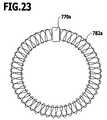
- the actuating sensorit can be advantageous for the actuating sensor to be disposed in a gap of a ring coil.
- a cross section of the field changing memberto vary in a direction of actuation of the actuating member.
- the volume of the field changing member that is penetrated by a flux of the fieldis increased following actuation of the at least one actuating member, namely when the field changing member is moved into the field of the field generating unit or moved out of the field.
- cross sectionit is expedient for the cross section to increase.
- a field changing member with an increasing cross sectioncan be constructed particularly easily.
- a particularly good couplingcan be achieved between the field generating unit and the actuating sensor when the field generating unit is coupled by a return path system to the actuating sensor.
- the return path systemis advantageously suited for leading a flux of the field generated by the field generating unit directly from the field generating unit to the actuating sensor. Undesired influences of the field generated by the field generating unit on control electronics of the drive unit are thereby avoided.
- the return path systemin the case of a magnetic field generating unit, it is expedient for the return path system to be a magnetic return path system.
- a magnetizable materialcan be used here for producing the return path system, for example, a mechanical coupling.
- the field generating unit, the return path system and the actuating sensordefine a recess, and that the field changing member is disposed so that it is at least partially introducible into the recess as a result of movement of the actuating member.
- a change in the field acting at the location of the actuating sensorcan thus be brought about in a simple and reliable manner.
- the design of the push-button unitis particularly simple when the recess has a substantially rectangular cross section.
- the actuating memberIn principle, it is conceivable for the actuating member to drive the field changing member or to be indirectly connected to it. However, the design of the push-button unit is even simpler when the actuating member carries the field changing member.
- the field generating unitcan be disposed on the power supply unit.
- the field generating unitcan be disposed on the power and control unit.
- All other elements, in particular, the field generating unitcan be disposed on the power and control unit. Consequently, no electric contacts are required between the actuating member and the power and control unit in order, for example, to prescribe a rotational speed with the actuating member.
- manufacturing tolerancescan thereby be easily compensated, for example, when the position of the power and control unit, after exchange thereof, is no longer identical owing to exchange for a different power and control unit, i. e., when the field changing member no longer assumes the original position relative to the field generating unit.
- the machineprefferably has at least two different operating modes, a first operating mode position of the at least one actuating member being associated with a first operating mode, and for the at least one actuating member to be rotatable about an axis of rotation from the first operating mode position to a second operating mode position, which is associated with a second operating mode of the machine, to switch the drive unit over from the first operating mode to the second operating mode.
- a configuration of the push-button unitallows a number of functions to be allocated to the actuating member. For example, it can serve as rotational speed prescribing member for prescribing a rotational speed of the drive unit and simultaneously as switch for switching over from a first to a second operating mode.
- two actuating sensorscan be provided and disposed so that there is detectable with the one actuating sensor a position of the at least one actuating member in the first operating mode position and/or a movement of the at least one actuating member in the first operating mode position, and with the second actuating sensor a position of the at least one actuating member in the second operating mode position and/or a movement of the at least one actuating member in the second operating mode position.
- the push-button unitcan thus be adapted to special requirements of a circuit that is used or its components.
- the electric motoradvantageously comprises a rotor and at least two motor windings.
- the electric motorhas to be electronically commutated.
- increased demandsare made on the motor control and/or regulation.
- high demandsare made on optimum starting behavior of the motor under load and on its dynamics, and, at the same time, the best possible efficiency at each operating point should be achieved, it is necessary to determine the position or location of the rotor of the motor, which is usually formed by a magnet. Only the precise rotor position makes it possible for the coils referred to as motor or stator windings to be supplied with electric current, in accordance with the purpose, at the required point in time of commutation.
- the designing of the motor controller so that the surgical machine can be controlled and/or regulated by a space vector pulse width modulation (SVPWM) methodimproves, in particular, starting of the motor and motor operation at low rotational speeds.
- SVPWMspace vector pulse width modulation
- all motor windingsare simultaneously supplied with electric current.
- PWMpulse width modulation
- PWMpulse width modulation
- PWMpulse width modulation
- Optimum design of the machineis accomplished when the motor controller comprises a control unit and a power unit. In this way, in particular, power consumption of the machine is minimized when the electric motor is at a standstill.
- Electronic commutationcan be achieved in a simple way by the power unit respectively comprising two power transistors for each of the at least two motor windings.
- the power unitrespectively comprising two power transistors for each of the at least two motor windings.
- positive and negative voltages in relation to a reference potentialcan be applied in a simple way to the at least two motor windings, even when only one DC voltage source is available as power supply.
- the machineis particularly maintenance-friendly when the electric motor is a brushless DC motor.
- the electric motorcan also be electronically commutated.
- At least one of the at least two motor windingsis separable from a power supply of the machine for a time interval t interrupt , that a CEMF (counterelectromotive force) of the at least one of the at least two motor windings is measurable during the time interval t interrupt , and that an actual position of the rotor is calculatable from the measured CEMF (counterelectromotive force).
- this means that the simultaneous supplying with electric currentis briefly interrupted in a specific manner for a certain time interval in the space vector pulse width modulation (SVPWM) method, namely at one, several or all of the motor windings.
- SVPWMspace vector pulse width modulation
- a determination of the rotor positioncan be further improved when all motor windings are simultaneously separable from the power supply of the machine for the time interval t interrupt .
- the CEMFcounterelectromotive force
- the CEMFcan thus be simultaneously determined at all motor windings, and any inaccuracies in the determination of the CEMF (counterelectromotive force) at only one motor winding will, therefore, have a less serious effect.
- the voltages applied to the at least two motor windingsare measurable before or at the start of the time interval t interrupt or before the measuring of the CEMF (counterelectromotive force), and for that motor winding at which the lowest voltage is measured to be connectable to a prescribed voltage potential.
- a time for the transient phenomenon of the systemis minimized by this procedure, i. e., the CEMF (counterelectromotive force) can be measured after a minimum waiting time.
- the design of the surgical machineis particularly simple when the prescribed voltage potential is ground.
- the motor controllerIn order to further optimize determination of the rotor position, it is advantageous for the motor controller to be so designed that the CEMF (counterelectromotive force) during the time interval t interrupt is not measured until after a transient time t transient .
- the CEMFcounterelectromotive force
- the motor controllerto be so designed that to determine the CEMF (counterelectromotive force), a voltage progression is measurable at the motor winding or motor windings not connected to the prescribed voltage potential, and for the transient time t transient to correspond at least to a time t constant until the voltages applied to the motor winding or motor windings not connected to the prescribed voltage potential are constant or almost constant in the course of time.
- This configurationallows the transient time t transient to be varied according to requirements. By determining the time t constant , the transient time t transient can be set in a specific manner and minimized.
- the motor controlleris preferably so designed that a constant value is prescribed for the time interval t interrupt .
- the motor controllercan thereby be considerably simplified.
- the motor controllercan, however, be advantageous for the motor controller to be so designed that the time interval t interrupt is alterable.
- the time interval t interruptcan thereby be increased or reduced if the time t constant is longer than the initially prescribed time interval t interrupt .
- Optimized operation of the machinecan be achieved by the motor controller being so designed that the duration of the time interval t interrupt is so prescribable that during the time interval t interrupt , the voltages applied to the motor winding or motor windings not connected to the prescribed voltage potential assume a constant or almost constant voltage value in the course of time.
- the time interval t interruptcan be adapted accordingly, whereby the interruption in the supplying of electric current to the motor windings becomes minimally short.
- the running smoothness of the motorin particular, at low rotational speeds and during the starting, is thereby improved.
- the motor controlleris preferably so designed that the time interval t interrupt is increasable when the time t constant is greater than the time interval t interrupt , and/or that the time interval t interrupt is reducible when the t constant is less than the time interval t interrupt . It is thereby ensured that the time interval t interrupt will never be longer than absolutely necessary to determine as accurately as possible the CEMF (counterelectromotive force) for detecting the rotor position.
- time interval t interruptit is conceivable to periodically vary the time interval t interrupt . It is, however, expedient for the motor controller to be so designed that the time interval t interrupt is alterable stepwise per revolution. In particular, it is expedient for the time interval t interrupt to be stepwise increasable or reducible. In this way, the time interval t interrupt can be altered until it corresponds at least to the time t constant , so as to be able to determine the CEMF (counterelectromotive force) safely and accurately.
- CEMFcounterelectromotive force
- the motor controlleris so designed that a specified position of the rotor is comparable with the actual position of the rotor as determined from the CEMF (counterelectromotive force) measurement, and that a field angle of the space vector pulse width modulation (SVPWM) is adjustable in accordance with the difference determined between specified position and actual position of the rotor.
- the motor controllerthus determines a deviation of the actual position from the specified position of the rotor and adjusts the field angle of the stator field generated by the motor windings on the basis of the position deviation determined. Optimum efficiency of the motor can thus be achieved.
- the motor controllerTo further increase the accuracy in determining the CEMF (counterelectromotive force), it is advantageous for the motor controller to be so designed that the CEMF (counterelectromotive force) is only measurable after the motor current of at least one of the at least two motor windings has dropped to zero. Any measurement errors caused by the flowing of a motor current when determining a CEMF (counterelectromotive force) can thus be avoided.
- the power supply unit and the motor controllerprefferably form a unit, and for the unit to be detachably connectable to the machine.
- Thishas, in particular, the advantage that all parts of the machine that are sensitive to heat and moisture can be removed for cleaning purposes, for example, for sterilization of the machine.
- the construction of the motor controller and the mains-independent power supply as a unitshortens the time required for preparing the surgical machine for use.
- the motor controllerprefferably comprises a connection circuit which does not connect a processor of the motor controller to the power supply unit until the electric motor is connected to the motor controller.
- a premature discharge, in particular, self-discharge, of a mains-independent power supply unitcan be avoided.
- processors of motor controllersusually have a considerably higher power consumption than other components of the controller.
- Self-discharge of the mains-independent power supply unitcan be avoided by activation of the motor controller only being made possible after connection of the motor controller to the electric motor.
- the design of the surgical machineis particularly simple when the electric motor comprises three motor windings.
- Surgical machines of the kind described at the outsetare known in a multitude of variants, especially as drilling and milling machines or saws. They are operated by control signals being generated by the motor controller for the electric motor in order to operate it at a certain rotational speed. Depending on the type of electric motor, rotational speeds of up to 70,000 revolutions per minute can be reached. Due to the construction, however, the efficiency of electric motors is not identical, and, in particular, not always optimal, at all rotational speeds.
- an efficiency of the electric motorcan be optimized essentially over the entire rotational speed range.
- Thiscan be accomplished, in accordance with a preferred embodiment of the invention, for example, in that an entire rotational speed range of the surgical machine is divided into at least one lower rotational speed range for low rotational speeds and at least one upper rotational speed range for higher rotational speeds than those in the at least one lower rotational speed range, in that the motor controller is so designed that a first controlling and/or regulating method for controlling and/or regulating the electric motor is performable in the at least one lower rotational speed range, and in that a second controlling and/or regulating method for controlling and/or regulating the electric motor is performable in the at least one upper rotational speed range.
- an actual rotational speed of the electric motor during operationcan also be determined in an optimized manner in dependence upon the rotational speed.
- first and/or the second controlling and/or regulating methodbe a pulse width modulation (PWM) method.
- PWMpulse width modulation
- DC motorscan be operated in a simple and optimized manner with this method.
- sinusoidal current and voltage progressionscan be generated by superposing a carrier frequency on digital voltage or current signals.
- the first controlling and/or regulating methodcan be a space vector pulse width modulation (SVPWM) method in which all motor windings are able to be simultaneously supplied with electric current.
- SVPWM methodhas the advantage over conventional pulse width modulation (PWM) methods that all motor windings are able to be simultaneously supplied with electric current, so that a smooth, jerk-free operation of the electric motor is also possible at particularly low rotational speeds. Furthermore, starting of the motor from a standstill is considerably improved by all motor windings being able to be simultaneously supplied with electric current.
- the motorcan comprise rotational speed detection sensors and for the motor controller to be so designed that the first controlling and/or regulating method is a method for controlling and/or regulating the surgical machine, in which the motor controller provides control signals for the electric motor in dependence upon an actual rotational speed determined with the rotational speed detection sensors.
- the rotational speed detection sensorsmay also serve to determine a position of the rotor of the electric motor.
- Use of rotational speed detection sensors, in particular, at low rotational speeds of the electric motorhas the advantage that the rotational speed can be determined considerably more precisely than, for example, by determining a CEMF (counterelectromotive force) generated at the motor winding or windings.
- the determination of the CEMF (counterelectromotive force)is more suitable at higher rotational speeds, as higher induction voltages are generated, in this case, and the detected signals can therefore be processed better.
- a particularly simple construction of the machineis obtained when a Hall system is provided for detecting an actual rotational speed of the electric motor and when the Hall system comprises the rotational speed detection sensors.
- Hall sensors as rotational speed detection sensorscan be made particularly small and integrated directly into the electric motor.
- a rotational speed limit value between the at least one lower rotational speed range and the at least one upper rotational speed rangeis unalterable.
- a switchover between the at least two controlling and/or regulating methodscan always take place at a desired rotational speed limit value.
- a rotational speed limit value between the at least one lower rotational speed range and the at least one upper rotational speed rangeis alterable. Depending on the operating situation, it is thus possible to specifically alter a switchover between the at least two controlling and/or regulating methods. Switching points can then be varied in a desired manner.
- a constant switchover between the at least two controlling and/or regulating methodscan be avoided in a simple way by the motor controller being so designed that a switchover from the first controlling and/or regulating method to the second controlling and/or regulating method takes place at a first switchover rotational speed and a switchover from the second controlling and/or regulating method to the first controlling and/or regulating method takes place at a second switchover rotational speed.
- Two switching pointscan thus be defined, namely at the transition from the lower rotational speed range to the higher rotational speed range, and vice versa. It is thus possible to separate the switchover times, i. e., a small variation in the actual rotational speed of the motor does not necessarily immediately result in a switchover to the other controlling and/or regulating method.
- first switchover rotational speedit is conceivable for the first switchover rotational speed to be less than the second switchover rotational speed. It is, however, particularly expedient for the first switchover rotational speed to be equal to or greater than the second switchover rotational speed.
- a switchover to the higher rotational speed rangetherefore takes place at a higher switchover rotational speed than the switchover from the higher rotational speed range to the lower rotational speed range. This therefore results in a hysteresis curve, as it were, with a range in which both the one and the other controlling and/or regulating methods are used for certain rotational speeds, but in dependence upon whether the rotational speed of the electric motor increases or decreases.
- the machineprefferably comprises a first and a second actuating member, and for the motor controller to be so designed that a rotational speed of the drive can be prescribed to the motor controller by actuating the first actuating member.
- the second actuating membercan serve to switch the machine over from a first operating mode to a second operating mode.
- the first actuating membercould be so designed that it enables a switchover from a first to a second operating mode. This could be achieved by, for example, the actuating member being rotatable about its longitudinal axis.
- One operating modecould also correspond to a switched-off state of the machine, the second operating mode or the second position of the actuating member to an operating position of the machine in which it is switched on, without it being a question of a special operating mode. It is thus possible to, on the one hand, prescribe a rotational speed of the drive with the first actuating member and, on the other hand, to also switch off the machine permanently in order to minimize risk of injury by a machine that has been put aside and not properly safeguarded.
- the motor controllercan also be advantageous for the motor controller to be so designed that a switchover from a first operating mode to a second operating mode of the drive is possible by actuating the second actuating member.
- the first operating modeis preferably clockwise operation of the drive, the second operating mode counterclockwise operation of the drive. This configuration allows actuation of the first actuating member for prescribing a rotational speed, with, for example, the drive switching over from clockwise operation to counterclockwise operation upon actuation of the second actuating member.
- the motor controllercan be so designed that a switchover from one operating mode to another operating mode is brought about by actuating the second actuating member once or by the drive only being operated in the other operating mode so long as the second actuating member is actuated.
- the motor controlleris so designed that the drive is operable in clockwise and/or counterclockwise operation and/or in oscillatory operation, during which the drive runs alternately and, in each case, equally long, in different directions of rotation, and/or in stair step operation.
- the driveis operated alternately in different directions of rotation, the drive being operated, in each case, somewhat longer in a first direction of rotation than in a second direction of rotation.
- a threadcan, for example, be cut in a simple way, for which purpose, the drive is always operated somewhat longer in forward direction for cutting the thread than in rearward direction.
- Oscillatory operationcan be advantageous, in particular, when working on surfaces, so as not to allow any onward movement of the instrument or tool connected to the machine.
- the second actuating memberFor switching over operation of the machine from clockwise or counterclockwise operation to oscillatory operation and/or vocational step operation, it can be advantageous for the second actuating member to be continuously actuatable at least during a prescribed switchover time.
- a motor controllerdoes not require an actuating member that has to be switched over mechanically from a first position to a second position.
- the actuating membercan be a pressure-sensitive sensor. If the actuating member is actuated longer than the prescribed switchover time, the machine can then, for example, transfer from clockwise or counterclockwise operation to oscillatory operation or vocational step operation.
- the motor controllercan be advantageously so designed that for switching over from clockwise or counterclockwise operation to oscillatory operation or vocational step operation the second actuating member is actuatable while the first actuating member is unactuated.
- a switchover between different operating modescan thus preferably only take place when the first operating member is unactuated, i.e., in particular, when no rotational speed is requested of the drive. This ensures that a switchover can only take place when the drive is at a standstill.
- the motor controlleris expediently so designed that a duration ranging from 2 to 5 seconds can be prescribed as switchover time. It is preferable for a switchover time of approximately 3 seconds to be prescribed.
- the motor controlleris advantageously so designed that oscillatory operation and/or mit step operation are maintainable even when the second actuating member, after actuation during the prescribed switchover time, is no longer actuated. This allows switchover of the drive permanently to another operating mode. This requires actuation of the second actuating member once only for at least the switchover time.
- the motor controlleris so designed that the drive can be switched over from oscillatory operation and/or mitral step operation to clockwise or counterclockwise operation by actuating the second actuating member for a duration which is shorter than the prescribed switchover time.
- the motor controllerprefferably to be so designed that the drive can be switched over from oscillatory operation or
- the motor controlleris so designed that after switchover from clockwise or counterclockwise operation to oscillatory operation or a step operation, the drive can first be switched over to vocational step operation after actuation of the first actuating member. If, for example, the drive is at a standstill, then, after actuation of the first actuating member, for example, to request a certain rotational speed of the drive, first only switchover to vocational step operation takes place. It is also conceivable to so design the motor controller that switchover to oscillatory operation first takes place after actuation of the rotational speed request. Switchover between successive step operation and oscillatory operation can take place in dependence upon a duration of actuation of the first actuating member or a requested rotational speed.
- the motor controlleris preferably so designed that the machine is operable in crawl step operation so long as a rotational speed, which lies below a switchover rotational speed, is prescribed with the first actuating member.
- a further operating modefor example, an oscillatory mode
- the motor controllerprefferably to be so designed that the machine can be switched over from vocational step operation to oscillatory operation when a rotational speed which lies above the switchover rotational speed is prescribed with the first actuating member. Switchover from vocational step operation to oscillatory operation, therefore, takes place simply by increasing the rotational speed request beyond a certain rotational speed.
- a rotational speed for operating the drivecan thus be prescribed with the first actuating member.
- Handling of the surgical machineis particularly simple when switchover from clockwise rotation of the electric motor to counterclockwise rotation of the electric motor is brought about by actuating the second actuating member.
- the switchovercan take place when the second actuating member is permanently pressed, or as long as it remains pressed, or by actuating the second actuating member once.
- the machineis advantageous for the machine to be operated in clockwise and/or counterclockwise operation and/or oscillatory operation, during which the electric motor runs alternately and, in each case, equally long in different directions of rotation, and/or mit step operation, during which the electric motor is alternately operated in different directions of rotation, the electric motor being operated, in each case, somewhat longer in clockwise rotation than in counterclockwise rotation.
- itcan be operated in the operating mode best suited therefor.
- Oscillatory operationcan, for example, be preferably used when machining drill holes or for use of the machine as trephine.
- Pilgrim step operation as described hereinaboveis advantageous when drill holes are to be provided with a thread. A stepwise cutting of the thread is thus possible.
- the second actuating memberis preferably actuated while the first actuating member is unactuated. It is thereby ensured that the drive will be at a standstill when the switchover takes place, i. e., a switchover to another operating mode cannot occur from full operation.
- switchover timeIn order to ensure that a switchover between two operating modes will not take place inadvertently; it is expedient for a duration ranging from 2 to 5 seconds to be prescribed as switchover time. It is particularly advantageous for a switchover time of approximately 3 seconds to be prescribed.
- switchover from oscillatory operation or pilgrim step operation to counterclockwise operationto be brought about by actuating the second actuating member for a duration which is shorter than the prescribed switchover time. If, for example, an instrument that is connected to the machine seizes during use of the machine, then switchover between the operating modes described hereinabove can be brought about in a simple way.
- switchover to stationary step operationtakes place first.
- a holecan be drilled in clockwise operation and the drill withdrawn in counterclockwise operation, for example.
- switchover to stationary step operation or oscillatory operation modea thread can be subsequently cut in the drilled hole.
- FIG. 1an exploded representation of a first embodiment of a surgical machine
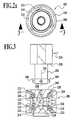
- FIG. 2a perspective view of a coupling device shown in FIG. 1 ;
- FIG. 2 aa plan view of the coupling device of FIG. 2 ;
- FIG. 3a sectional view taken along line 3 - 3 in FIG. 2 a;
- FIG. 4 aa side view of a power and control unit
- FIG. 4 ba sectional view taken along line 4 - 4 in FIG. 4 a;
- FIG. 5 aa perspective view of a second embodiment of a surgical machine
- FIG. 5 ban exploded representation of the machine shown in FIG. 5 a;
- FIG. 6a front view of the machine of FIG. 5 a;
- FIG. 7a sectional view taken along line 7 - 7 in FIG. 6 ;
- FIG. 8a sectional view similar to FIG. 7 of the machine disassembled in FIG. 5 b;
- FIG. 8 aan enlarged view of component assemblies shown on the right in FIG. 8 ;
- FIG. 9a side view of a third embodiment of a surgical machine
- FIG. 10a front end view of the machine shown in FIG. 9 ;
- FIG. 11an exploded representation of the machine shown in FIG. 9 ;
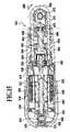
- FIG. 12a sectional view taken along line 12 - 12 in FIG. 10 ;
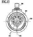
- FIG. 13a sectional view taken along line 13 - 13 in FIG. 12 ;
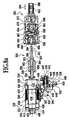
- FIG. 14a sectional view taken along line 14 - 14 in FIG. 12 ;
- FIG. 15a sectional view taken along line 15 - 15 in FIG. 12 ;
- FIG. 16a circuit diagram of a surgical machine
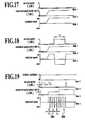
- FIG. 17a schematic representation of a time-related progression of operation of a surgical machine
- FIG. 18a further representation of a time-related progression of operation of a surgical machine
- FIG. 19a further representation of a time-related progression of operation of a surgical machine
- FIG. 20a schematic representation of a surgical accumulator machine
- FIG. 21a schematic representation of a push-button/sensor assembly
- FIG. 22a schematic representation of a field changing member moved relative to the actuating sensor.
- FIG. 23an example embodiment of an actuating sensor disposed in a gap of a ring coil.
- FIG. 1shows an accumulator machine in the form of a surgical drilling or milling machine, generally designed by reference numeral 100 , which is disassembled into component assemblies described in more detail hereinbelow.
- the accumulator machine 100comprises a housing 102 with a motor mount 106 defining a longitudinal axis 104 , and an integrally formed grip 108 protruding substantially transversely from the motor mount 106 .
- the grip 108serves to receive a power and control unit 110 , which can be pushed in through an opening 112 of the grip 108 , which faces away from the motor mount 106 .
- a cover 114serves to close the opening 112 and secure the power and control unit 110 in the grip 108 .
- the cover 114comprises an inside seal 116 which, when the cover 114 is placed on the grip 108 , presses against a rim 118 of the grip 108 , which surrounds the opening 112 .
- the housing 102has in the area of the grip 108 a substantially rhombic cross section with rounded-off housing edges. Not shown is a spring that is optionally provided in the grip 108 for aiding removal of the power and control unit 110 after removal of the cover 114 .
- a drive unit 120is insertable parallel to the longitudinal axis 104 into the substantially hollow-cylindrical motor mount 106 .
- the drive unit 120comprises an electric drive in the form of an electrically commutated sensorless DC motor, which is surrounded by a motor housing 122 .
- a front end opening 126 of keyhole-like shape of the motor mount 106 and of the grip 108 in the area of transition from the motor mount 106 to the grip 108can be closed with a plate 128 of substantially keyhole-like shape serving as frame.
- a borehole 130is provided on the plate 128 concentrically with the longitudinal axis 104 .
- the two actuating membersform together with the plate 128 a push-button unit 140 .
- the plate 128has a circumferential rim 142 , which projects transversely to the longitudinal axis 104 and is configured so as to correspond to a rim 144 of the opening 126 that projects in a single step.
- a seal, not shown, to be inserted between the rims 142 and 144ensures a germ-free closure of the opening 126 with the plate 128 forming a closure element.
- Also provided in the proximity of the rim 144is a short cylindrical pin 148 , which protrudes from a stop plate 146 in the direction towards the plate 128 and enters a recess, not shown, of the plate 128 in order to prevent movement of the plate 128 transversely to the longitudinal axis 104 .
- a rotor 150 of the electric motorcan be removed from the drive unit 120 also when the latter is fixed to the plate 128 , namely through the borehole 130 .
- the rotor 150comprises an elongated, substantially cylindrical bearing shaft 152 , to which an end ball bearing 154 and a front ball bearing 156 are attached for rotatable mounting of the rotor 150 in the motor housing 122 .
- the bearing shaft 152is constructed in the form of a fork-shaped coupling piece 160 , which can engage in a positively locked manner an identically constructed coupling piece, not shown, of a further shaft connected to the latter and can cause this further shaft to rotate.
- the permanent magnet 158can be of one-piece construction or made up of individual disks. In this way, eddy current losses can be reduced. Both the stability and the flexural rigidity of the rotor 150 are increased by the threading of the bored permanent magnet 158 onto the bearing shaft 152 .
- a rotor armoring 164is provided to protect the permanent magnet 158 , namely in the form of a thin sleeve made of rust-proof and non-magnetic material surrounding the permanent magnet 158 .
- the rotor armoring 164serves to increase the mechanical strength of the rotor 150 , which is important, in particular, at very high rotational speeds. Furthermore, the rotor armoring 164 forms a protection for the permanent magnet 158 against corrosion, so that, in particular, also neodymium-iron-boron magnets which are susceptible to corrosion can be used.
- the ball bearings 154 and 156have radial grooves, not shown, on the outer ring, on which damping elements can be mounted. The resulting mounting is thereby made easier to disassemble and reassemble for maintenance purposes than a damping element mounted in the motor housing 122 , which is difficult to access. Emergency running properties of the motor are improved by using ceramic ball bearings or ball bearings with individual ceramic components.
- a head 170 of the attachment screw 166can be sealed off in a fluid-tight manner in relation to the housing 102 by a sealing ring 172 .
- the externally threaded section 168can be screwed to an internally threaded section, not shown, at the rear end of the motor housing 122 .
- the drive unit 120 fixed to the plate 128is pushed into the motor mount 106 , it is then drawn, by screwing to the attachment screw 166 , against the rear end 174 of the motor mount 106 and hence the rim 142 against the rim 144 .
- the attachment screw 166solely by releasing the attachment screw 166 the plate 128 with the drive unit 120 can be detached from the housing 102 and taken out of it.
- the coupling device 180serves to connect a coupling piece 182 with three coupling elements 184 protruding from the latter in the form of short cylindrical pins.
- the coupling piece 182forms a rear end of a gear block 162 , at the front end of which a coupling piece 186 is provided with a tool receptacle 188 for receiving an instrument or tool for connection to the gear block 162 .
- a toolcan be released from the tool receptacle 188 by pulling back an outer actuating sleeve 190 with a ring flange in the direction towards the coupling device 180 .
- a contact block 192Protruding from the motor housing 122 in the direction towards the grip 108 is a contact block 192 , from which, in turn, three motor contacts 194 , aligned in parallel with one another, protrude, which are each connected to two of a total of three motor windings 199 .
- the motor contacts 194are in the form of hollow contact pins, which have transverse boreholes, through which the motor windings are threaded and soldered.
- the contact block 192serves as mount for the motor contacts 194 and is made of a high-temperature-resistant plastic material. Furthermore, it is sealed off in relation to the motor housing 122 .
- the motor contacts 194are aligned parallel to a longitudinal axis 196 of the grip 108 .
- the power and control unit 110 shaped in accordance with the grip 108which is non-circular inside, has three connection contacts 198 , which correspond to the motor contacts 194 , and into which the protruding motor contacts 194 extend when the power and control unit 110 is pushed into the grip 108 .
- a secure contactis achieved by the connection contacts 198 being built with limited movement, i. e., floatingly, into the power and control unit 110 .
- Dimension, shape and position tolerances of the connection contacts 198 relative to the motor contacts 194can, therefore, be compensated. Transition resistances between the connection contacts 198 and the motor contacts 194 are thereby prescribed in a defined manner.
- the power and control unit 110can be easily pushed into the grip 108 and also removed from it again.
- the power and control unit 110There are also provided on the power and control unit 110 four charge contacts 200 , by means of which the power and control unit 110 can be connected by connection cables or by a direct connection to a charger 202 for charging accumulator cells 206 disposed in a sleeve-like housing 204 of the power and control unit 110 .
- the coupling device 180comprises a rotary ring 208 having two symmetrically disposed ring grooves 210 open in the direction towards the longitudinal axis 104 . Inserted into the rotary ring 208 from both sides are rotationally symmetrical coupling members 212 and 214 , which define a hollow-cylindrical coupling receptacle 216 extending through the coupling device 180 coaxially with the longitudinal axis 104 , and which are rotationally fixedly connected to each other.
- the coupling receptacle 216serves to receive the coupling piece 182 .
- Three coupling receptacles 218 extending from the coupling receptacle 216 parallel to the longitudinal axis 104serve to receive the coupling elements 184 , so that these, coming from the front, enter the coupling receptacle 218 from the side.
- One respective end of the helical springs 224 and 226is rotationally fixedly connected to the rotary ring 208 , the other respective end of the helical springs 224 and 226 to the coupling members 212 and 214 .
- the coupling receptacles 218do not extend through the entire coupling device 180 , but end blind in the coupling member 214 .
- Rotationally fixedly connected to the rotary ring 208are three locking elements 228 , which, upon rotation of the rotary ring 208 relative to the coupling members 212 , are moved in circumferential direction. They have two edges, each extending transversely through a coupling receptacle 218 , namely a first slide edge 230 and a second slide edge 232 .
- the first slide edge 230is turned through an angle of approximately 30° relative to the longitudinal axis 104
- the second slide edge 232which faces in the direction towards the plate 128 , through an angle of approximately 90°.
- the coupling piece 182which is disposed on an end sleeve 234 of the gear block 162 , is introduced into the coupling receptacle 216 so that the coupling elements 184 enter the coupling receptacle 218 , the coupling elements 184 then first abut on the first slide edge 230 . If the coupling piece 182 is moved further into the coupling receptacle 216 , the first slide edge 230 then slides on the coupling elements 184 , whereby these are displaced against the spring forces of the helical springs 224 and 226 in circumferential direction together with the rotary ring 208 against the coupling members 212 and 214 .
- the helical springs 224 and 226force the locking elements 228 back again in circumferential direction into their basic position.
- the second slide edge 232is moved by the spring forces along the coupling elements 184 and forces these even further into the coupling receptacle 218 .
- a ring edge 238 of the end sleeve 234 facing towards the coupling device 180abuts on an end face 240 of the coupling device 180 , and the second slide edge 232 holds the coupling elements 184 under tension parallel to the longitudinal axis 104 so that the ring edge 238 is held free of play on the end face 240 .
- the rotary ring 208need only be turned against the spring forces of the helical springs 224 and 226 relative to the coupling members 212 and 214 until the locking elements 228 release the coupling receptacles 218 so that the coupling elements 184 can be pulled out of these again parallel to the longitudinal axis 104 .
- the coupling members 212 and 214are provided with three through-bores 242 extending parallel to the longitudinal axis 104 , through which the screws 178 can be inserted and screwed to the threaded bores 176 of the plate 128 .
- the coupling device 180can also be released from the plate 128 when the latter is connected to the housing 102 .
- the rotor 150can then be pulled out of the drive unit 120 . Therefore, for maintenance of the ball bearings 154 and 156 , the plate 128 need not be released, removal of the coupling device 180 is sufficient.
- a motor controller 246is disposed, which, in particular, comprises the printed circuit boards 248 and 250 shown in FIG. 4 b , on which the electronic components required for controlling the accumulator machine 100 are disposed.
- the control housing 244is fixedly connected to the housing 204 . Screws 252 serve to secure the motor controller 246 in the control housing 244 .
- a separating plate 254 separating the motor controller 246 from the accumulator cells 206can be screwed with screws 252 to the control housing 244 .
- a hollow bar 256projects from the separating plate 254 parallel to the longitudinal axis 196 and extends through the housing 204 as far as the end of the latter. At its end facing way from the motor controller 246 , the bar 256 is provided with an internally threaded section 258 .
- a matching housing cover 262 for closing the housing 204can be connected to the housing 204 , which at its other end is connected to the control housing 244 . Except for the connection contacts 198 and charge contacts 200 that are led out, the power and control unit 110 is completely encapsulated.
- the return path systemis disposed on either side of a gap 268 in the control housing 244 , so that a magnetic soft iron element 270 of parallelepipedal shape disposed on the power/speed push-button 136 can enter an opening 272 formed by the return path system and change a magnetic flux in the return path system.
- a rotational speed prescribing signalcan be transmitted to the power and control unit 110 without any direct electrical connection between the power/speed push-button 136 and the power and control unit 110 .
- a narrow slot 274 disposed parallel to the gap 268is provided on an upper side of the control housing 244 .
- two light barriers 276 and 278extending through the latter, which are either operated by visible light, in which case corresponding cutouts are then provided in the control housing 244 , or are formed by infrared light barriers, in which case no openings are then required in the control housing 244 .
- the light barrier 276serves as operating mode switchover sensor, which can be contactlessly actuated from an end of the operating mode selector switch 138 projecting into the housing 102 , namely when the end is moved so far into the slot 274 that the light barrier 276 is interrupted.
- the light barrier 278serves as operating mode activation sensor, which is contactlessly actuatable by an operating mode activation actuating member, not shown. This can, for example, be disposed on the drive unit 120 , or not, and, when present, enters the slot 274 and interrupts the light barrier 278 . For example, a certain operating mode can thereby be specifically activated or deactivated, in particular, an oscillatory operation of the accumulator machine 100 .
- the power and control unit 110 described hereinabovecan be used for different machines, in particular, also for the embodiments described hereinbelow and not only for the accumulator machine 100 .
- the power and control unit 110can be of shorter construction than shown in FIG. 4 b , in particular, when only two accumulator cells 206 are disposed below the separating plate 254 .
- the housing 204can then be shortened accordingly.
- the grip 108 of the housing 102can then also be shortened accordingly.
- a shortening of the grip 108 in the described manneris appropriate.
- the accumulator cells 206are directly accessible and hence easy to exchange, which is necessary at regular intervals owing to the normally limited life span of the accumulator cells 206 .
- all electronic components of the accumulator machine 100are accommodated in the power and control unit 110 , which does not undergo sterilization.
- the sensitive electronicsare, therefore, not exposed to any harmful environmental conditions, in particular, heat and moisture in a sterilizer. Furthermore, it is not necessary to overly protect these from soiling or to additionally encapsulate them.
- the electronics of the accumulator machine 100can also contain in addition to the motor controller 246 the described sensors for controlling rotational speed, direction of rotation and operating mode. Furthermore, monitoring elements for the accumulator cells 206 and communication elements to the charger 202 can be provided.
- the power and control unit 110carries no mechanical elements for resetting the actuating members, i. e., in particular, the power/speed push-button 136 and the operating mode selector switch 138 , whereby the actuating forces for the actuating members are minimized.
- the motor controller 246comprises programmable Hall ICs, so that a slight pushing, for example, of the power/speed push-button 136 , first results in an increase in the rotational speed proportionally to the push-button path of the power/speed push-button 136 and only subsequently in an overproportional increase in the rotational speed of the motor up to the maximum rotational speed.
- the power and control unit 110is only placed in an operable state under certain conditions. This can, for example, be the case when the power and control unit 110 is pushed into the grip 108 , and the connection contacts 198 are in contact with the motor contacts 194 .
- the motor controller 146is activated periodically, for example, at an interval of one second to ten seconds, preferably six seconds, for a few milliseconds, and inquires the prescribed conditions for activation. If these do not apply, the motor controller 246 is deactivated again.
- accumulator cells 206Cell blocks of widely differing technology are used as accumulator cells 206 .
- accumulator packsare created, which have both the necessary dimensions and a prescribed nominal voltage of preferably 14.4 volts.
- thismakes it possible to employ cells with lithium ions, lithium polymer, NiMH and NiCd technology.
- twelve NiMH cells with 1.2 volts each and hence a total voltage of 14.4 voltscan be used in cases where it is a question of a high capacity.
- four lithium-ion cellswith a nominal voltage of 3.6 volts each, i.
- lithium-ion cells on the basis of manganesecan also be used, as a result of which an external protective wiring of the power and control unit 110 can be dispensed with.
- FIGS. 5 a to 8 aA second embodiment of a surgical machine in the form of a jigsaw 300 is shown in FIGS. 5 a to 8 a .
- a large number of the components and component assemblies of the jigsaw 300correspond to components or component assemblies of the accumulator machine 100 , as is clearly apparent from a comparison of the Figures.
- the housings 102 and 302are identical, and also the power and control unit 110 , not shown in FIGS. 5 a to 8 a , which is designed in like manner to that in the accumulator machine 100 and can be held in the grip 308 of the housing 302 with a cover, not shown, which is identical to the cover 114 .
- the housing 302comprises a motor mount 306 defining a longitudinal axis 304 , and a grip 308 protruding substantially transversely from the motor mount 306 and defining a longitudinal axis 396 .
- a drive unit 320can be pushed parallel to the longitudinal axis 304 into an opening 326 defined on the front side of the housing 302 in the area of the motor mount 306 and the area of transition to the grip 308 .
- the drive unit 320comprises a motor housing 322 , which is detachably fixable to a plate 328 corresponding in design to the opening 326 .
- the motor housing 322extends somewhat with a sleeve-shaped section 324 through a circular opening of the plate 328 .
- a power/speed push-button 336is movably mounted on the plate 328 and disposed at a position at which the operating mode selector switch 138 is provided on the accumulator machine 100 . Furthermore, a covering 338 is provided at the position at which the power/speed push-button 136 is provided on the accumulator machine 100 , so that the plates 128 and 328 are substantially identical.
- the plate 328 with the power/speed push-button 326forms a push-button unit 340 .
- a rim 342 of the plate 328is sealed off in a germ-proof manner by a seal, not shown, in relation to the rim 344 of the opening 326 .
- a stop plate 346 corresponding to the stop plate 126 at the lower end of the opening 326limits movement of the plate 328 towards the housing 302 .
- the drive unit 320 pushed into the motor mount 306can be fixed with an attachment screw 366 corresponding to the attachment screw 166 .
- the attachment screw 366has an externally threaded section 368 and a head 370 , which serves as stop for a rear end 374 of the motor mount 306 and is sealed off with a sealing ring 372 in relation to the rear end 374 for germ-free closure of an opening 375 provided in the rear end 374 .
- a contact block 392Protruding from the motor housing 322 in the direction towards the grip 308 is a contact block 392 , from which, in turn, three motor contacts 394 identical to the motor contacts 194 protrude parallel to the longitudinal axis 396 in the form of gold-plated contact pins in the direction towards the grip 308 .
- a rotor 350is part of the drive unit 320 and is removable from the latter when a gear block 362 , which is fixable to the plate 328 , thereby embracing the cylindrical section 324 , is removed from the plate 328 .
- the rotor 350is substantially identical in design to the rotor 150 and comprises a bearing shaft 352 , and a cylindrical permanent magnet 358 mounted on the bearing shaft 352 and having a borehole 359 which corresponds to the bearing shaft 352 .
- a ball bearing 354 in the form of a ring bearingis fixed to an end of the bearing shaft 352 that faces in the direction towards the rear end 374 .
- collar-like clamping elements 400 and 402which, on the one hand, form a corrosion protection together with a thin, sleeve-like rotor armoring 364 made of amagnetic material, and, on the other hand, hold the permanent magnet 358 on the bearing shaft 352 .
- a front end of the bearing shaft 352forms a coupling piece 360 , which has a cutout 361 disposed transversely to the longitudinal axis 304 , in which a clamping member 363 is inserted, which is pushable into a groove of a drive wheel 404 of the gear block 362 and serves as catch for the drive wheel 404 .
- a tool receptacle 388into which, for example, a saw blade is insertable and fixable with a screw 406 .
- FIGS. 5 a and 5 bAn internal design of the components and component assemblies of the jigsaw 300 described in FIGS. 5 a and 5 b will be explained in more detail hereinbelow with reference to FIGS. 7 , 8 and 8 a.
- a receiving space 309which is formed in the grip 308 , and into which the power and control unit 110 is insertable, is, as mentioned hereinabove, closable with a cover corresponding to the cover 114 , and the circumferential seal 116 placed in the cover 114 presses against a lower rim 318 of the housing 302 and thereby closes it in a germ-proof manner.
- the housinghas a total of three openings, namely an opening 312 for insertion of the power and control unit 110 into the grip 308 , the opening 375 in the rear end 374 of the motor mount 306 for placement of the attachment screw 366 and the opening 326 for insertion of the drive unit 320 into the housing 302 .
- Closure elements for the openingsare thus formed by the attachment screw 366 , the cover 114 , not shown, and the plate 328 .
- Sealing elementsare respectively provided for sealing the openings 312 , 374 and 326 with the closure elements described hereinabove in a germ-free manner, and for preparing the jigsaw 300 , like the accumulator machine 100 , after insertion of the non-sterile power and control unit 110 , for use in a sterile area, for example, an operating theater.
- a sleeve-shaped connecting piece 408Disposed at the rear end of the drive unit 320 is a sleeve-shaped connecting piece 408 , which has an internal thread 410 , which corresponds in design to the external thread of the externally threaded section 368 .
- the connecting piece 408expands twice, with a single step in each case, and the second expansion 412 serves to receive the ball bearing 354 .
- the expansion 412is followed by a radially outwardly protruding ring flange 414 , which is inserted into a rear end of the motor housing 322 and is sealed off with a ring seal 416 .
- two spacer rings 418 and 419which rest against the inside of the motor mount 306 when the drive unit 320 is inserted. They are preferably made of a damping material. They further serve to hold the contact block 392 on the bottom of the motor housing 322 .
- a sleeve-like winding memberInserted coaxially with the longitudinal axis 304 into the motor housing 322 is a sleeve-like winding member, onto which three motor windings 399 are wound.
- An end of the motor contacts 394 extending into the motor housing 322is provided with a transverse bore 424 , through which the motor windings are led and soldered.
- a connection area of the motor windings 399can, therefore, be kept very short by the threading-through.
- the front portion 324 of the motor housing 322extends through a borehole 330 provided for that purpose in the plate 328 .
- a ring-shaped stop 426 on the motor housing 322formed by a single-step reduction in the external diameter in the transition to the portion 324 , abuts directly on the plate 328 .
- All electrically conductive elements of the motor housing 322are fully encapsulated by casting, in particular, the motor windings 399 disposed between the winding member 420 and the motor housing 322 , and the motor contacts 394 held in the contact block 392 .
- a rotationally symmetrical receiving space 428 in the interior of the drive unit 320serves to receive the rotor 350 described in detail hereinabove.
- Two boreholes 430 and 432are provided one over the other parallel to the longitudinal axis 304 on the plate 328 for receiving the power/speed push-button 336 and the covering 338 .
- the covering 338 inserted in the borehole 432is sealed off in a germ-proof manner with a ring seal 434 in relation to the plate 328 .
- the covering 338has on the outside an ergonomically shaped outer surface, on which an operator can preferably support his middle finger and/or ring finger.
- the power/speed push-button 336comprises a sleeve-shaped, fixed bearing member 436 , which is led through the borehole 430 , and on which there is provided for movement coaxially with a longitudinal axis 440 of the borehole 430 a push-button element 438 , which is held by a helical spring 442 in a basic position protruding from the plate 328 .
- a bellows seal 444 fixed, on the one hand, on the bearing member 436 and, on the other hand, on the push-button element 438ensures a germ-free sealing of the power/speed push-button 336 relative to the plate 328 .
- the push-button element 438has a pin extending through the borehole 430 . At the end of the pin that extends into the housing 302 there protrudes downwards a small plate 448 having such a width that it can be pushed into the gap 268 of the power and control unit 110 . It serves to actuate the Hall sensor 264 of the rotational speed prescribing sensor 282 of the power and control unit 110 .
- the small soft iron plate 448extends so far downwards that it can enter the gap 268 at the same position as a small iron plate, not shown in the Figures, which is disposed on the power/speed push-button 136 of the accumulator machine 100 .
- the power/speed push-button 136 and the operating mode selector switch 138 and also the power/speed push-button 336can be removed from the plate 328 for maintenance purposes.
- the motor windings 399 wound onto the winding member 420are cast in a cold casting process under vacuum or under normal atmosphere with epoxy resin, so that no cavities arise in which germs can settle owing to the open construction of both accumulator machine 100 and jigsaw 300 . Furthermore, the casting serves as protection against vibrations and as protection against hot steam during sterilization of the machines.
- the cold casting substancecan be advantageously filled with fillers, which improve heat transfer away from the motor windings 399 .
- the drive unit 320thus comprises a three-phase electronically commutated motor, which is of identical design and sensorless in all embodiments, i. e., in particular, no Hall system with Hall sensors is present for gaining knowledge of a position or orientation of the rotor 350 , which is necessary for supplying the motor windings 399 with current.
- a rotor positionis determined by a sensorless method, as will be explained hereinbelow. In principle, it is, however, also conceivable to provide sensors for detecting a rotor position in the drive unit 320 .
- the gear block 362serves to convert a rotation of the rotor 350 into an oscillating movement, indicated by arrow 450 , coaxially with the longitudinal axis 304 , of a coupling part 452 having a coupling receptacle 388 for receiving a saw blade.
- the gear block 362has a substantially conical housing, in the rear end of which a drive wheel 404 , mounted by the ball bearing 356 , is mounted.
- the coupling piece 360 of the rotor 350is insertable into the cylindrical receptacle 456 of the drive wheel 404 .
- the ball bearing 356is held in a bearing member 458 , which extends further in the direction towards the front end of the gear block 362 .
- a drive wheel 462mounteded about a longitudinal axis 460 transversely to the longitudinal axis 304 on the bearing member 458 is a drive wheel 462 , which is driven by the drive wheel 404 .
- the drive wheels 404 and 462can be configured either as cylindrical gear and gear wheel or as two bevel gears.
- the drive wheel 462carries parallel to the longitudinal axis 460 a connecting rod 464 , on which two ball bearings 466 and 467 are mounted, which are held in a borehole 468 of a drive rod 470 arranged coaxially with the longitudinal axis 304 .
- the coupling part 452is connected by a shaft 472 to the connecting rod 464 , so that as a result of a rotation of the drive wheel 462 , the connecting rod 464 moves the drive rod 470 periodically, and the drive rod 470 moves the shaft 472 back and forth, as indicated by arrow 450 , parallel to the coupling part 452 , which is mounted by means of slide bearings in the housing 454 .
- the gear block 362is connected by a quick-acting closure to the front portion 324 of the motor housing 322 . If the gear block 362 is removed, the rotor 350 can be removed from the drive unit 320 without the latter having to be taken out of the housing 302 .
- the drive wheels 404 and 462form a reduction stage, so that the motor can be operated in a range with higher efficiency, for which the power and control unit 110 has only to provide a relatively low motor current for a high rotational speed of the motor to be achievable.
- the rotational speed of the motordoes not drop to a range below the power maximum of the motor, but nevertheless the motor current does not rise sharply.
- the reduction stageis positive for the power balance of the machine, in other words, the machine can be operated longer with the same power made available by the power and control unit 110 .
- the operating time of the machinedoes, however, depend strongly on the amount of motor current withdrawn.
- a pivotably mounted locking element 474is provided on the power/speed push-button 336 , as also on the power/speed push-button 136 . It is mounted on the push-button element 438 for pivotal movement about an axis parallel to the longitudinal axis 440 . In a first extreme pivot position, it allows movement of the push-button element 438 parallel to the longitudinal axis 440 , in another extreme pivot position, movement of the push-button element 438 in the direction towards the plate 328 is locked.
- the locking element 474thus serves to secure the machine against unintentional operation thereof.
- FIGS. 9 to 15A third embodiment of a surgical machine according to the invention in the form of an oscillating saw, generally designated by reference numeral 500 , is shown in FIGS. 9 to 15 .
- the design of the saw 500corresponds substantially to that of the jigsaw 300 , so that identical parts or components are designated by reference numerals between 500 and 699 , which are used in analogy with the reference numerals 300 to 499 used to describe the jigsaw 300 .
- the power and control unit 110comprising the motor controller 246 serves as power supply.
- the power and control unit 110can be pushed into a receiving space 509 of a grip 508 of a housing 502 and secured by closing the opening 512 with a cover corresponding to the cover 114 .
- the grip 508protrudes substantially transversely from a motor mount 506 , which defines a longitudinal axis 504 .
- the cover for closing the opening 512has a seal, which presses against a lower rim of the grip 518 and thereby closes the receiving space 509 in a germ-proof manner.
- a drive unit 520is mounted on a plate 528 and comprises a motor housing 522 , from which a contact block 592 , additionally secured with spacer rings 618 and 619 , protrudes in the direction towards the grip 508 .
- the contact block 592carries three pin-like motor contacts 594 , which protrude parallel to the longitudinal axis 596 and are conductively connected to three motor windings 599 .
- Two boreholes 630 and 632 disposed one above the other on the plate 528 and orientated parallel to the longitudinal axis 504serve to receive a power/speed push-button 536 and a covering 538 , respectively, which together with the plate 528 form a push-button unit 540 .
- a substantially keyhole-like opening of the housing 502 in the area of the motor mount 506 and in the area of transition to the grip 508serves for insertion of the drive unit 520 into the housing 502 .
- a rim 542 of the plateis sealed off in relation to a rim 544 of the opening 526 by a seal, not shown.
- a stop plate 546is provided in the lower area of the opening 526 .
- the drive unit 520 inserted into the housing 502is secured by an attachment screw 566 with an externally threaded section 568 being screwed to an internal thread 610 of a connection piece 608 at the rear end of the drive unit 520 .
- an attachment screw 566with an externally threaded section 568 being screwed to an internal thread 610 of a connection piece 608 at the rear end of the drive unit 520 .
- a seal 572 between the head 570 and the rim of the opening 575the latter is sealed in a germ-proof manner.
- a sleeve-shaped portion 524 at the front end of the drive unit 520extends through a borehole 530 of the plate 528 and is connectable to a gear block 562 , which carries at its front end an angular part 680 , which is provided with a peg-shaped tool receptacle 588 , on which, for example, a saw blade with a corresponding borehole can be placed and secured.
- a rotor 550can be removed from the drive unit 520 .
- the rotorcomprises a substantially cylindrical bearing shaft 552 , to the rear end of which a ball bearing 554 is fixed.
- a cylindrical permanent magnet 558 with a borehole extending in the direction of the longitudinal axis 504is positioned on the bearing shaft 552 and simultaneously protected and held in circumferential direction by a thin, sleeve-like rotor armoring and at its end faces by collar-like clamping elements 600 and 602 .
- a front end of the bearing shaft 552forms a coupling piece 560 , which is engageable in a rotationally fixed manner with a drive wheel 604 .
- connection piece 608expands twice in a single step in the internal diameter, and the ball bearing 554 is held in the area of its second expansion 612 .
- a ring flange 614 protruding radially outwardly from the connection piece 608serves in conjunction with a ring seal 616 to close a rear end of the motor housing 522 .
- Inserted into the motor housing 522is a winding member 620 , onto which the motor windings 599 are wound. As described in conjunction with the design of the jigsaw 300 , the motor windings 599 are also fully encapsulated by cold casting.
- ends 622 of the motor contacts 594 pointing towards the longitudinal axisare provided with transverse boreholes 624 , through which the motor windings 599 are threaded and soldered.
- a ring-shaped stop 626 in the area of transition of the motor housing 522 in the front portion 527abuts directly on the plate 528 .
- the push-button unit 540is identical in design to the push-button unit 340 .
- the power/speed push-button 536comprises a bearing member 636 , which is inserted into the bore 630 and is sealed off in a germ-proof manner in relation to the plate 528 .
- the ergonomically shaped covering 538 for supporting a middle or ring fingeris sealed off in relation to the plate 528 by a ring seal surrounding the borehole 632 .
- a push-button element 638is mounted in the bearing member 636 for displacement coaxially with a longitudinal axis 640 .
- the push-button elementwhen it is not actuated, is held by a helical spring 642 in a basic position in which it projects maximally from the plate 528 .
- a bellows seal 644 secured, on the one hand, on the bearing member 636 and, on the other hand, on the push-button element 638serves to seal the power/speed push-button 536 relative to the plate 528 .
- the push-button element 638comprising a pin 646 extending into the housing 502 carries at the protruding end of the pin 646 a downwardly facing small soft iron plate 648 having dimensions that enable it to be pushed into the gap 268 of the power and control unit 110 .
- the gear block 562has at its rear end facing towards the plate 528 a receptacle 650 for the coupling piece 560 .
- a receptacle 650for the coupling piece 560 .
- a cutout 652into which a projection in the receptacle 650 can enter, whereby a rotationally fixed connection is established between the drive wheel 604 and the bearing shaft 552 .
- the drive wheel 604is mounted by means of the ball bearing 556 on an inner part of the housing.
- the inner part of the housingis mounted for rotation about the longitudinal axis 504 relative to an outer housing 656 and is held by a helical spring in a basic position in which the gear block 562 is locked on the plate 528 .
- the drive wheel 604is part of a reduction unit 660 , with which a rotational speed of the drive unit 520 can be reduced to a desired value.
- a drive shaft 662mounted by means of two ball bearings 664 and 666 in the inner part 654 of the housing, parallel to, but offset somewhat from the longitudinal axis 504 , is driven by the reduction unit 660 .
- a front end of the drive shaft 662is in the form of an eccentric pin 668 , which carries a ball bearing 670 with a spherical outer surface, which is held in a fork-shaped end 672 of an oscillating lever 676 .
- the oscillating leveris fixed to a shaft 678 , which is mounted in the angular piece 680 for rotation about an axis of rotation 682 , and the end of which protruding from the angular piece 680 forms the tool receptacle 588 .
- the axis of rotation 682extends perpendicularly to the longitudinal axis 504 and intersects it.
- the shaft 678is mounted by means of two ball bearings 684 and 686 in the angular piece 680 .
- the drive shaft 662being disposed parallel to the bearing shaft 552 , a particularly small outer diameter of the outer housing 656 and a symmetrical design of the latter can be achieved.
- the drive shaft 662could also be disposed coaxially with the bearing shaft 552 .
- All three machines described hereini. e., the accumulator machine 100 , the jigsaw 300 and the oscillating saw 500 have in common that the drive units 120 , 320 and 520 and the coupling device 180 and the gear blocks 362 and 562 are not sealed off. This has the advantage that these machine areas are made germ-free inwards during the sterilization. Oil can be sprayed through the above-mentioned elements for lubrication of the bearings. Alternatively, the drive units could also be sealed off, and the bearings lubricated for the entire life span. The interior could nevertheless be made germ-free by sterilization if a membrane valve as described in International Patent Application PCT/EP03/00911 were provided.
- Connection possibilities for a washing machinecan be additionally provided in the area of the machine drive and in the area of the machine output, so that soiled channels of rotatory drives can be manually cleaned, and likewise soiled tool receptacles 588 for saw blades.
- the rotational speed prescribing sensor 282 of the power and control unit 110can be contactlessly actuated with the power/speed push-buttons 136 , 336 and 536 .
- Corresponding signals arriving at the motor controller 246 from the rotational speed prescribing sensorare processed, and the motor contacts 194 and the motor windings 199 , 399 and 599 , respectively, connected thereto are acted upon accordingly with current via the connection contacts 198 , in order to operate the drive units 120 , 320 and 520 at a corresponding rotational speed.
- the operating mode selector switch 138serves to contactlessly actuate the light barrier 276 , which, in the event of interruption, switches the accumulator machine 100 over from clockwise operation to counterclockwise operation.
- the light barrier 278can be contactlessly actuated with the projection 280 . If this occurs, the motor controller 246 activates or deactivates the basic possibility of switching the accumulator machine 100 over to oscillatory operation or
- Time-related progressions of a rotational speed of the bearing shaft 152 and of a percent actuation of the power/speed push-button 136 serving as rotational speed sensorare shown in FIG. 17 .
- the operating mode selector switch 138 serving as clockwise (cw)/counterclockwise (ccw) switchis not actuated in the time-related progressions shown in FIG. 17 .
- the accumulator machine 100can be operated not only in clockwise operation or counterclockwise operation, as described with reference to FIGS. 17 and 18 , but also in oscillatory operation or in stair step operation. The precondition for this is that the accumulator machine 100 first be at a standstill.
- the operating mode selector switch 138If the operating mode selector switch 138 is pressed for a time t 2 , which is greater than a prescribed switchover time, which, for example, can be prescribed in a range of one second to ten seconds, it can then be signalized, for example, by an acoustic signal generated by the power and control unit 110 that the accumulator machine 100 was switched over into the oscillatory mode. If, after the switchover, the power/speed push-button 136 is pressed only to maximally X %, then the motor controller 246 activates the drive unit 120 in the so-called vocational step operation, as indicated by arrow 284 in FIG. 19 .
- a prescribed switchover timewhich, for example, can be prescribed in a range of one second to ten seconds
- the drive unitperiodically changes the direction of rotation, but the drive unit 120 is respectively operated during a time t 3 in clockwise rotation and during a time t 4 in counterclockwise rotation, the time t 3 being somewhat greater than the time t 4 .
- Switchover to the actual oscillatory operation, indicated by arrow 286 in FIG. 19during which the drive unit 120 is respectively operated for an equal length of time in clockwise rotation and counterclockwise rotation, only takes place when the power/speed push-button 136 is pressed more than the preset X %. If the operating mode selector switch 138 is actuated for a short time, the motor controller 246 switches the accumulator machine 100 over to counterclockwise operation. Switchover to oscillatory operation, in turn, requires continuous actuation of the operating mode selector switch 138 , with the drive unit 120 at a standstill, for at least the prescribed switchover time.
- a surgical accumulator machineis shown purely schematically in FIG. 20 .
- Thiscan also be, for example, the above-described accumulator machine 100 , the jigsaw 300 or the oscillating saw 500 , which can differ in the details of their design from the accumulator machine 700 .
- the accumulator machine 700comprises a housing 712 , in one part of which a sensorless electric motor 714 is disposed parallel to the longitudinal axis of this housing part and drives a drive shaft, not shown, of the accumulator machine 700 .
- a coupling 716Disposed at the end of the drive shaft is a coupling 716 , with which the accumulator machine 700 can be connected to any of kind of tool, for example, drills, mills, chisels and also saws or gear units for connection to one of the tools cited by way of example.
- the power pack 720comprises a rechargeable battery or accumulator cell 722 and a motor controller 724 .
- a power/speed push-button 726 and an operating mode selector switch 728are provided, which can be pressed into the grip 718 substantially parallel to a longitudinal axis of the electric motor 714 .
- the power/speed push-button 726 and the operating mode selector switch 728together form a push-button unit.
- the electric motor 714is preferably a sensorless brushless DC motor, i. e., no rotational speed detection sensors are provided for detecting a rotor movement and a position of a rotor magnet, referred to hereinbelow as rotor, of the electric motor 714 .
- rotora rotor magnet
- an actuation signalcan be contactlessly generated by moving the power/speed push-button 726 .
- a Hall sensor 770 with three connection contacts 772serves as actuating sensor. It is positioned between two short legs 774 of two L-shaped soft iron plates 776 , which results in a parallelepipedal structure comprised of the legs 774 and the Hall sensor 770 disposed between these and, possibly, further soft iron elements filling out a space between the legs 774 . Disposed between free ends 778 of two long legs 780 of the two soft iron plates 776 is a cylindrical bar magnet 782 , as provided, for example, on the power and control unit 110 in the form of the bar magnet 266 .
- a frame-shaped structurewhich defines an opening 784 delimited by the long legs 780 , the bar magnet 782 and the short legs 774 with the Hall sensor 770 lying between these, as provided, for example, on the power and control unit 110 in the form of the opening 272 , with a rectangular cross section.
- a parallelepipedal soft iron element 788Disposed on the push-button 726 shown schematically in FIG. 21 , on an end face 786 of the main body 725 that faces away from an actuating button 727 , is a parallelepipedal soft iron element 788 , as provided, for example, on the power and control unit 110 in the form of the parallelepipedal soft iron element 270 .
- the parallelepipedal soft iron element 788protrudes in the direction of a longitudinal axis 790 of the main body 725 , and an end face 792 of the parallelepipedal soft iron element 788 is inclined through 450 relative to the end face 786 of the main body 725 .
- the frame structure with the Hall sensor 770is so disposed relative to the push-button 726 that as a result of actuation of the push-button 726 in the direction of arrow 794 in FIG. 21 , i. e., parallel to the longitudinal axis 790 , the main body 725 can be moved with the parallelepipedal soft iron element 788 into the opening 784 .
- the ferromagnetic, parallelepipedal soft iron element 788has, starting from a front end edge 796 , cross sections which increase parallel to the end face 786 , which is indicated by the two cutting planes 798 and 800 drawn in FIG. 22 , which both extend parallel to the end face 786 .
- the two push-buttons 726 and 728are so disposed that they remain, in particular, in a battery-operated drive machine, and the power and control unit 720 can be removed with the motor controller 724 and the battery 722 before sterilization of the accumulator machine 700 .
- the push-button unit 729which comprises the field changing members in the form of the parallelepipedal soft iron elements 788 , thus remains on the accumulator machine 700 . Therefore, no electrical contacts that are required for generating an actuation signal remain within the accumulator machine 700 , for with control electronics, for example, in the form of motor controller 724 , the Hall sensors 770 are also completely removed.
- the special arrangement of the Hall sensor 770 relative to the bar magnet 782allows their spatial allocation to be fixed in a definite and permanent manner. A readjustment, as in conventional systems, is not necessary. Any manufacturing tolerances in the size and shape of the parallelepipedal soft iron element 788 and the opening 784 have a far less critical effect on operation of the push-button unit 729 than is the case in conventional systems with a magnet mounted on the push-button and moved relative to the Hall sensor 770 .
- an actuating sensore.g., a hall sensor
- a ring coil 782 amay be disposed in a gap of a ring coil 782 a .
- the actuating sensor 770 a and ring coil 782 aoperate similarly to the hall sensor 770 and bar magnet 782 .
Landscapes
- Health & Medical Sciences (AREA)
- Surgery (AREA)
- Life Sciences & Earth Sciences (AREA)
- Biomedical Technology (AREA)
- Medical Informatics (AREA)
- Orthopedic Medicine & Surgery (AREA)
- Oral & Maxillofacial Surgery (AREA)
- Engineering & Computer Science (AREA)
- Dentistry (AREA)
- Heart & Thoracic Surgery (AREA)
- Nuclear Medicine, Radiotherapy & Molecular Imaging (AREA)
- Molecular Biology (AREA)
- Animal Behavior & Ethology (AREA)
- General Health & Medical Sciences (AREA)
- Public Health (AREA)
- Veterinary Medicine (AREA)
- Surgical Instruments (AREA)
- Control Of Multiple Motors (AREA)
- Connection Of Motors, Electrical Generators, Mechanical Devices, And The Like (AREA)
Abstract
Description
Claims (21)
Applications Claiming Priority (1)
| Application Number | Priority Date | Filing Date | Title |
|---|---|---|---|
| PCT/EP2005/004059WO2006111173A1 (en) | 2005-04-16 | 2005-04-16 | Surgical machine and method for controlling and/or regulating the same |
Related Parent Applications (1)
| Application Number | Title | Priority Date | Filing Date |
|---|---|---|---|
| PCT/EP2005/004059ContinuationWO2006111173A1 (en) | 2005-04-16 | 2005-04-16 | Surgical machine and method for controlling and/or regulating the same |
Publications (2)
| Publication Number | Publication Date |
|---|---|
| US20080077149A1 US20080077149A1 (en) | 2008-03-27 |
| US8029510B2true US8029510B2 (en) | 2011-10-04 |
Family
ID=35447342
Family Applications (1)
| Application Number | Title | Priority Date | Filing Date |
|---|---|---|---|
| US11/974,182Active2028-02-08US8029510B2 (en) | 2005-04-16 | 2007-10-10 | Surgical machine and method for controlling and/or regulating a surgical machine |
Country Status (4)
| Country | Link |
|---|---|
| US (1) | US8029510B2 (en) |
| EP (1) | EP1871242B1 (en) |
| JP (1) | JP4892546B2 (en) |
| WO (1) | WO2006111173A1 (en) |
Cited By (434)
| Publication number | Priority date | Publication date | Assignee | Title |
|---|---|---|---|---|
| US20110301577A1 (en)* | 2010-05-10 | 2011-12-08 | Markus Simmen | Medical Instrument Having A Detachable Handle |
| US20120035596A1 (en)* | 2010-08-04 | 2012-02-09 | Tegg Troy T | Disposable Drive Interface for Longitudinal Movement of an Elongate Medical Device |
| DE102014005769A1 (en)* | 2013-12-30 | 2015-07-02 | National Taiwan University | Hand robots for orthopedic surgery and related control method |
| US20180078246A1 (en)* | 2015-04-08 | 2018-03-22 | Sciencemedic Co., Ltd. | Surgical handpiece having direction-shifting function |
| US10076340B2 (en) | 2012-05-23 | 2018-09-18 | Stryker Corporation | Surgical tool system with a tool unit that includes a power generating unit and a battery and control module that is releasably attached to the tool unit for energizing and controlling the power generating unit |
| US20180289410A1 (en)* | 2012-06-04 | 2018-10-11 | Depuy Mitek, Llc | Methods and Devices for Surgical Guide Pin Placement |
| US10149682B2 (en) | 2010-09-30 | 2018-12-11 | Ethicon Llc | Stapling system including an actuation system |
| US10149680B2 (en) | 2013-04-16 | 2018-12-11 | Ethicon Llc | Surgical instrument comprising a gap setting system |
| US10159483B2 (en) | 2015-02-27 | 2018-12-25 | Ethicon Llc | Surgical apparatus configured to track an end-of-life parameter |
| US10172616B2 (en) | 2006-09-29 | 2019-01-08 | Ethicon Llc | Surgical staple cartridge |
| US10172620B2 (en) | 2015-09-30 | 2019-01-08 | Ethicon Llc | Compressible adjuncts with bonding nodes |
| US10177700B2 (en) | 2016-10-31 | 2019-01-08 | Zimmer, Inc. | Surgical power tool with critical error handler |
| US10180463B2 (en) | 2015-02-27 | 2019-01-15 | Ethicon Llc | Surgical apparatus configured to assess whether a performance parameter of the surgical apparatus is within an acceptable performance band |
| US10188385B2 (en) | 2014-12-18 | 2019-01-29 | Ethicon Llc | Surgical instrument system comprising lockable systems |
| US10201349B2 (en) | 2013-08-23 | 2019-02-12 | Ethicon Llc | End effector detection and firing rate modulation systems for surgical instruments |
| US10201364B2 (en) | 2014-03-26 | 2019-02-12 | Ethicon Llc | Surgical instrument comprising a rotatable shaft |
| US10201363B2 (en) | 2006-01-31 | 2019-02-12 | Ethicon Llc | Motor-driven surgical instrument |
| US10206678B2 (en) | 2006-10-03 | 2019-02-19 | Ethicon Llc | Surgical stapling instrument with lockout features to prevent advancement of a firing assembly unless an unfired surgical staple cartridge is operably mounted in an end effector portion of the instrument |
| US10206677B2 (en) | 2014-09-26 | 2019-02-19 | Ethicon Llc | Surgical staple and driver arrangements for staple cartridges |
| US10206605B2 (en) | 2015-03-06 | 2019-02-19 | Ethicon Llc | Time dependent evaluation of sensor data to determine stability, creep, and viscoelastic elements of measures |
| US10211586B2 (en) | 2017-06-28 | 2019-02-19 | Ethicon Llc | Surgical shaft assemblies with watertight housings |
| US10206676B2 (en) | 2008-02-14 | 2019-02-19 | Ethicon Llc | Surgical cutting and fastening instrument |
| US10213201B2 (en) | 2015-03-31 | 2019-02-26 | Ethicon Llc | Stapling end effector configured to compensate for an uneven gap between a first jaw and a second jaw |
| US10213262B2 (en) | 2006-03-23 | 2019-02-26 | Ethicon Llc | Manipulatable surgical systems with selectively articulatable fastening device |
| US10226249B2 (en) | 2013-03-01 | 2019-03-12 | Ethicon Llc | Articulatable surgical instruments with conductive pathways for signal communication |
| US10231794B2 (en) | 2011-05-27 | 2019-03-19 | Ethicon Llc | Surgical stapling instruments with rotatable staple deployment arrangements |
| US10238391B2 (en) | 2013-03-14 | 2019-03-26 | Ethicon Llc | Drive train control arrangements for modular surgical instruments |
| US10238386B2 (en) | 2015-09-23 | 2019-03-26 | Ethicon Llc | Surgical stapler having motor control based on an electrical parameter related to a motor current |
| US10245033B2 (en) | 2015-03-06 | 2019-04-02 | Ethicon Llc | Surgical instrument comprising a lockable battery housing |
| US10245029B2 (en) | 2016-02-09 | 2019-04-02 | Ethicon Llc | Surgical instrument with articulating and axially translatable end effector |
| US10245035B2 (en) | 2005-08-31 | 2019-04-02 | Ethicon Llc | Stapling assembly configured to produce different formed staple heights |
| US10245042B2 (en)* | 2012-03-13 | 2019-04-02 | Medtronic Xomed, Inc. | Check valve vented sterilizable powered surgical handpiece |
| US10245027B2 (en) | 2014-12-18 | 2019-04-02 | Ethicon Llc | Surgical instrument with an anvil that is selectively movable about a discrete non-movable axis relative to a staple cartridge |
| US10245032B2 (en) | 2005-08-31 | 2019-04-02 | Ethicon Llc | Staple cartridges for forming staples having differing formed staple heights |
| US10258332B2 (en) | 2010-09-30 | 2019-04-16 | Ethicon Llc | Stapling system comprising an adjunct and a flowable adhesive |
| US10258333B2 (en) | 2012-06-28 | 2019-04-16 | Ethicon Llc | Surgical fastening apparatus with a rotary end effector drive shaft for selective engagement with a motorized drive system |
| US10258331B2 (en) | 2016-02-12 | 2019-04-16 | Ethicon Llc | Mechanisms for compensating for drivetrain failure in powered surgical instruments |
| US10258418B2 (en) | 2017-06-29 | 2019-04-16 | Ethicon Llc | System for controlling articulation forces |
| US10265074B2 (en) | 2010-09-30 | 2019-04-23 | Ethicon Llc | Implantable layers for surgical stapling devices |
| US10265068B2 (en) | 2015-12-30 | 2019-04-23 | Ethicon Llc | Surgical instruments with separable motors and motor control circuits |
| US10271849B2 (en) | 2015-09-30 | 2019-04-30 | Ethicon Llc | Woven constructs with interlocked standing fibers |
| US10271846B2 (en) | 2005-08-31 | 2019-04-30 | Ethicon Llc | Staple cartridge for use with a surgical stapler |
| US10278702B2 (en) | 2004-07-28 | 2019-05-07 | Ethicon Llc | Stapling system comprising a firing bar and a lockout |
| US10278780B2 (en) | 2007-01-10 | 2019-05-07 | Ethicon Llc | Surgical instrument for use with robotic system |
| US10293100B2 (en) | 2004-07-28 | 2019-05-21 | Ethicon Llc | Surgical stapling instrument having a medical substance dispenser |
| US10292704B2 (en) | 2015-12-30 | 2019-05-21 | Ethicon Llc | Mechanisms for compensating for battery pack failure in powered surgical instruments |
| US10299878B2 (en) | 2015-09-25 | 2019-05-28 | Ethicon Llc | Implantable adjunct systems for determining adjunct skew |
| US10299787B2 (en) | 2007-06-04 | 2019-05-28 | Ethicon Llc | Stapling system comprising rotary inputs |
| US10299792B2 (en) | 2014-04-16 | 2019-05-28 | Ethicon Llc | Fastener cartridge comprising non-uniform fasteners |
| US10307163B2 (en) | 2008-02-14 | 2019-06-04 | Ethicon Llc | Detachable motor powered surgical instrument |
| US10307170B2 (en) | 2017-06-20 | 2019-06-04 | Ethicon Llc | Method for closed loop control of motor velocity of a surgical stapling and cutting instrument |
| US10314589B2 (en) | 2006-06-27 | 2019-06-11 | Ethicon Llc | Surgical instrument including a shifting assembly |
| USD851762S1 (en) | 2017-06-28 | 2019-06-18 | Ethicon Llc | Anvil |
| US10327767B2 (en) | 2017-06-20 | 2019-06-25 | Ethicon Llc | Control of motor velocity of a surgical stapling and cutting instrument based on angle of articulation |
| US10327769B2 (en) | 2015-09-23 | 2019-06-25 | Ethicon Llc | Surgical stapler having motor control based on a drive system component |
| US10335148B2 (en) | 2010-09-30 | 2019-07-02 | Ethicon Llc | Staple cartridge including a tissue thickness compensator for a surgical stapler |
| US10335145B2 (en) | 2016-04-15 | 2019-07-02 | Ethicon Llc | Modular surgical instrument with configurable operating mode |
| USD854151S1 (en) | 2017-06-28 | 2019-07-16 | Ethicon Llc | Surgical instrument shaft |
| US10357247B2 (en) | 2016-04-15 | 2019-07-23 | Ethicon Llc | Surgical instrument with multiple program responses during a firing motion |
| US10363036B2 (en) | 2015-09-23 | 2019-07-30 | Ethicon Llc | Surgical stapler having force-based motor control |
| US10363031B2 (en) | 2010-09-30 | 2019-07-30 | Ethicon Llc | Tissue thickness compensators for surgical staplers |
| US10363037B2 (en) | 2016-04-18 | 2019-07-30 | Ethicon Llc | Surgical instrument system comprising a magnetic lockout |
| US10368865B2 (en) | 2015-12-30 | 2019-08-06 | Ethicon Llc | Mechanisms for compensating for drivetrain failure in powered surgical instruments |
| US10368864B2 (en) | 2017-06-20 | 2019-08-06 | Ethicon Llc | Systems and methods for controlling displaying motor velocity for a surgical instrument |
| US10376263B2 (en) | 2016-04-01 | 2019-08-13 | Ethicon Llc | Anvil modification members for surgical staplers |
| US10390841B2 (en) | 2017-06-20 | 2019-08-27 | Ethicon Llc | Control of motor velocity of a surgical stapling and cutting instrument based on angle of articulation |
| US10398433B2 (en) | 2007-03-28 | 2019-09-03 | Ethicon Llc | Laparoscopic clamp load measuring devices |
| US10398434B2 (en) | 2017-06-29 | 2019-09-03 | Ethicon Llc | Closed loop velocity control of closure member for robotic surgical instrument |
| US10405859B2 (en) | 2016-04-15 | 2019-09-10 | Ethicon Llc | Surgical instrument with adjustable stop/start control during a firing motion |
| US10413294B2 (en) | 2012-06-28 | 2019-09-17 | Ethicon Llc | Shaft assembly arrangements for surgical instruments |
| US10420549B2 (en) | 2008-09-23 | 2019-09-24 | Ethicon Llc | Motorized surgical instrument |
| US10420550B2 (en) | 2009-02-06 | 2019-09-24 | Ethicon Llc | Motor driven surgical fastener device with switching system configured to prevent firing initiation until activated |
| US10426467B2 (en) | 2016-04-15 | 2019-10-01 | Ethicon Llc | Surgical instrument with detection sensors |
| US10426481B2 (en) | 2014-02-24 | 2019-10-01 | Ethicon Llc | Implantable layer assemblies |
| US10426471B2 (en) | 2016-12-21 | 2019-10-01 | Ethicon Llc | Surgical instrument with multiple failure response modes |
| US10426463B2 (en) | 2006-01-31 | 2019-10-01 | Ehticon LLC | Surgical instrument having a feedback system |
| US10441279B2 (en) | 2015-03-06 | 2019-10-15 | Ethicon Llc | Multiple level thresholds to modify operation of powered surgical instruments |
| US10441285B2 (en) | 2012-03-28 | 2019-10-15 | Ethicon Llc | Tissue thickness compensator comprising tissue ingrowth features |
| US10448950B2 (en) | 2016-12-21 | 2019-10-22 | Ethicon Llc | Surgical staplers with independently actuatable closing and firing systems |
| US10448948B2 (en) | 2016-02-12 | 2019-10-22 | Ethicon Llc | Mechanisms for compensating for drivetrain failure in powered surgical instruments |
| US10456137B2 (en) | 2016-04-15 | 2019-10-29 | Ethicon Llc | Staple formation detection mechanisms |
| US10463370B2 (en) | 2008-02-14 | 2019-11-05 | Ethicon Llc | Motorized surgical instrument |
| US10485539B2 (en) | 2006-01-31 | 2019-11-26 | Ethicon Llc | Surgical instrument with firing lockout |
| US10485543B2 (en) | 2016-12-21 | 2019-11-26 | Ethicon Llc | Anvil having a knife slot width |
| US10485536B2 (en) | 2010-09-30 | 2019-11-26 | Ethicon Llc | Tissue stapler having an anti-microbial agent |
| US10492785B2 (en) | 2016-12-21 | 2019-12-03 | Ethicon Llc | Shaft assembly comprising a lockout |
| US10492783B2 (en) | 2016-04-15 | 2019-12-03 | Ethicon, Llc | Surgical instrument with improved stop/start control during a firing motion |
| USD869655S1 (en) | 2017-06-28 | 2019-12-10 | Ethicon Llc | Surgical fastener cartridge |
| US10499914B2 (en) | 2016-12-21 | 2019-12-10 | Ethicon Llc | Staple forming pocket arrangements |
| US10517596B2 (en) | 2016-12-21 | 2019-12-31 | Ethicon Llc | Articulatable surgical instruments with articulation stroke amplification features |
| US10517590B2 (en) | 2007-01-10 | 2019-12-31 | Ethicon Llc | Powered surgical instrument having a transmission system |
| US10517594B2 (en) | 2014-10-29 | 2019-12-31 | Ethicon Llc | Cartridge assemblies for surgical staplers |
| US10524790B2 (en) | 2011-05-27 | 2020-01-07 | Ethicon Llc | Robotically-controlled surgical stapling devices that produce formed staples having different lengths |
| US10524787B2 (en) | 2015-03-06 | 2020-01-07 | Ethicon Llc | Powered surgical instrument with parameter-based firing rate |
| US10531887B2 (en) | 2015-03-06 | 2020-01-14 | Ethicon Llc | Powered surgical instrument including speed display |
| US10537325B2 (en) | 2016-12-21 | 2020-01-21 | Ethicon Llc | Staple forming pocket arrangement to accommodate different types of staples |
| US10568625B2 (en) | 2016-12-21 | 2020-02-25 | Ethicon Llc | Staple cartridges and arrangements of staples and staple cavities therein |
| US10568652B2 (en) | 2006-09-29 | 2020-02-25 | Ethicon Llc | Surgical staples having attached drivers of different heights and stapling instruments for deploying the same |
| US10568626B2 (en) | 2016-12-21 | 2020-02-25 | Ethicon Llc | Surgical instruments with jaw opening features for increasing a jaw opening distance |
| US10575868B2 (en) | 2013-03-01 | 2020-03-03 | Ethicon Llc | Surgical instrument with coupler assembly |
| US10588626B2 (en) | 2014-03-26 | 2020-03-17 | Ethicon Llc | Surgical instrument displaying subsequent step of use |
| US10588633B2 (en) | 2017-06-28 | 2020-03-17 | Ethicon Llc | Surgical instruments with open and closable jaws and axially movable firing member that is initially parked in close proximity to the jaws prior to firing |
| US10588623B2 (en) | 2010-09-30 | 2020-03-17 | Ethicon Llc | Adhesive film laminate |
| US10588632B2 (en) | 2016-12-21 | 2020-03-17 | Ethicon Llc | Surgical end effectors and firing members thereof |
| USD879808S1 (en) | 2017-06-20 | 2020-03-31 | Ethicon Llc | Display panel with graphical user interface |
| USD879809S1 (en) | 2017-06-20 | 2020-03-31 | Ethicon Llc | Display panel with changeable graphical user interface |
| US10617417B2 (en) | 2014-11-06 | 2020-04-14 | Ethicon Llc | Staple cartridge comprising a releasable adjunct material |
| US10617412B2 (en) | 2015-03-06 | 2020-04-14 | Ethicon Llc | System for detecting the mis-insertion of a staple cartridge into a surgical stapler |
| US10617416B2 (en) | 2013-03-14 | 2020-04-14 | Ethicon Llc | Control systems for surgical instruments |
| US10617418B2 (en) | 2015-08-17 | 2020-04-14 | Ethicon Llc | Implantable layers for a surgical instrument |
| US10617413B2 (en) | 2016-04-01 | 2020-04-14 | Ethicon Llc | Closure system arrangements for surgical cutting and stapling devices with separate and distinct firing shafts |
| US10624861B2 (en) | 2010-09-30 | 2020-04-21 | Ethicon Llc | Tissue thickness compensator configured to redistribute compressive forces |
| US10624633B2 (en) | 2017-06-20 | 2020-04-21 | Ethicon Llc | Systems and methods for controlling motor velocity of a surgical stapling and cutting instrument |
| US10631859B2 (en) | 2017-06-27 | 2020-04-28 | Ethicon Llc | Articulation systems for surgical instruments |
| US10639115B2 (en) | 2012-06-28 | 2020-05-05 | Ethicon Llc | Surgical end effectors having angled tissue-contacting surfaces |
| US10646220B2 (en) | 2017-06-20 | 2020-05-12 | Ethicon Llc | Systems and methods for controlling displacement member velocity for a surgical instrument |
| US10660640B2 (en) | 2008-02-14 | 2020-05-26 | Ethicon Llc | Motorized surgical cutting and fastening instrument |
| US10667808B2 (en) | 2012-03-28 | 2020-06-02 | Ethicon Llc | Staple cartridge comprising an absorbable adjunct |
| US10667809B2 (en) | 2016-12-21 | 2020-06-02 | Ethicon Llc | Staple cartridge and staple cartridge channel comprising windows defined therein |
| US10675028B2 (en) | 2006-01-31 | 2020-06-09 | Ethicon Llc | Powered surgical instruments with firing system lockout arrangements |
| US10675027B2 (en) | 2013-01-23 | 2020-06-09 | Ethicon Llc | Surgical instrument with selectable integral or external power source |
| US10682134B2 (en) | 2017-12-21 | 2020-06-16 | Ethicon Llc | Continuous use self-propelled stapling instrument |
| US10682142B2 (en) | 2008-02-14 | 2020-06-16 | Ethicon Llc | Surgical stapling apparatus including an articulation system |
| US10687806B2 (en) | 2015-03-06 | 2020-06-23 | Ethicon Llc | Adaptive tissue compression techniques to adjust closure rates for multiple tissue types |
| US10687813B2 (en) | 2017-12-15 | 2020-06-23 | Ethicon Llc | Adapters with firing stroke sensing arrangements for use in connection with electromechanical surgical instruments |
| US10695062B2 (en) | 2010-10-01 | 2020-06-30 | Ethicon Llc | Surgical instrument including a retractable firing member |
| US10695063B2 (en) | 2012-02-13 | 2020-06-30 | Ethicon Llc | Surgical cutting and fastening instrument with apparatus for determining cartridge and firing motion status |
| US10695058B2 (en) | 2014-12-18 | 2020-06-30 | Ethicon Llc | Surgical instrument systems comprising an articulatable end effector and means for adjusting the firing stroke of a firing member |
| US10702267B2 (en) | 2007-03-15 | 2020-07-07 | Ethicon Llc | Surgical stapling instrument having a releasable buttress material |
| US10716565B2 (en) | 2017-12-19 | 2020-07-21 | Ethicon Llc | Surgical instruments with dual articulation drivers |
| US10716614B2 (en) | 2017-06-28 | 2020-07-21 | Ethicon Llc | Surgical shaft assemblies with slip ring assemblies with increased contact pressure |
| USD890784S1 (en) | 2017-06-20 | 2020-07-21 | Ethicon Llc | Display panel with changeable graphical user interface |
| US10729501B2 (en) | 2017-09-29 | 2020-08-04 | Ethicon Llc | Systems and methods for language selection of a surgical instrument |
| US10729509B2 (en) | 2017-12-19 | 2020-08-04 | Ethicon Llc | Surgical instrument comprising closure and firing locking mechanism |
| US10736628B2 (en) | 2008-09-23 | 2020-08-11 | Ethicon Llc | Motor-driven surgical cutting instrument |
| US10736630B2 (en) | 2014-10-13 | 2020-08-11 | Ethicon Llc | Staple cartridge |
| US10736636B2 (en) | 2014-12-10 | 2020-08-11 | Ethicon Llc | Articulatable surgical instrument system |
| US10743875B2 (en) | 2017-12-15 | 2020-08-18 | Ethicon Llc | Surgical end effectors with jaw stiffener arrangements configured to permit monitoring of firing member |
| US10743872B2 (en) | 2017-09-29 | 2020-08-18 | Ethicon Llc | System and methods for controlling a display of a surgical instrument |
| US10743873B2 (en) | 2014-12-18 | 2020-08-18 | Ethicon Llc | Drive arrangements for articulatable surgical instruments |
| US10743851B2 (en) | 2008-02-14 | 2020-08-18 | Ethicon Llc | Interchangeable tools for surgical instruments |
| US10743870B2 (en) | 2008-02-14 | 2020-08-18 | Ethicon Llc | Surgical stapling apparatus with interlockable firing system |
| US10743849B2 (en) | 2006-01-31 | 2020-08-18 | Ethicon Llc | Stapling system including an articulation system |
| US10743874B2 (en) | 2017-12-15 | 2020-08-18 | Ethicon Llc | Sealed adapters for use with electromechanical surgical instruments |
| US10751076B2 (en) | 2009-12-24 | 2020-08-25 | Ethicon Llc | Motor-driven surgical cutting instrument with electric actuator directional control assembly |
| US10758229B2 (en) | 2016-12-21 | 2020-09-01 | Ethicon Llc | Surgical instrument comprising improved jaw control |
| US10758230B2 (en) | 2016-12-21 | 2020-09-01 | Ethicon Llc | Surgical instrument with primary and safety processors |
| US10765425B2 (en) | 2008-09-23 | 2020-09-08 | Ethicon Llc | Robotically-controlled motorized surgical instrument with an end effector |
| US10765427B2 (en) | 2017-06-28 | 2020-09-08 | Ethicon Llc | Method for articulating a surgical instrument |
| US10765429B2 (en) | 2017-09-29 | 2020-09-08 | Ethicon Llc | Systems and methods for providing alerts according to the operational state of a surgical instrument |
| US10772625B2 (en) | 2015-03-06 | 2020-09-15 | Ethicon Llc | Signal and power communication system positioned on a rotatable shaft |
| US10772629B2 (en) | 2017-06-27 | 2020-09-15 | Ethicon Llc | Surgical anvil arrangements |
| US10779826B2 (en) | 2017-12-15 | 2020-09-22 | Ethicon Llc | Methods of operating surgical end effectors |
| US10779820B2 (en) | 2017-06-20 | 2020-09-22 | Ethicon Llc | Systems and methods for controlling motor speed according to user input for a surgical instrument |
| US10779824B2 (en) | 2017-06-28 | 2020-09-22 | Ethicon Llc | Surgical instrument comprising an articulation system lockable by a closure system |
| US10779821B2 (en) | 2018-08-20 | 2020-09-22 | Ethicon Llc | Surgical stapler anvils with tissue stop features configured to avoid tissue pinch |
| US10779825B2 (en) | 2017-12-15 | 2020-09-22 | Ethicon Llc | Adapters with end effector position sensing and control arrangements for use in connection with electromechanical surgical instruments |
| US10780539B2 (en) | 2011-05-27 | 2020-09-22 | Ethicon Llc | Stapling instrument for use with a robotic system |
| US10779903B2 (en) | 2017-10-31 | 2020-09-22 | Ethicon Llc | Positive shaft rotation lock activated by jaw closure |
| US10796471B2 (en) | 2017-09-29 | 2020-10-06 | Ethicon Llc | Systems and methods of displaying a knife position for a surgical instrument |
| US10806448B2 (en) | 2014-12-18 | 2020-10-20 | Ethicon Llc | Surgical instrument assembly comprising a flexible articulation system |
| US10806449B2 (en) | 2005-11-09 | 2020-10-20 | Ethicon Llc | End effectors for surgical staplers |
| US10813639B2 (en) | 2017-06-20 | 2020-10-27 | Ethicon Llc | Closed loop feedback control of motor velocity of a surgical stapling and cutting instrument based on system conditions |
| US10828028B2 (en) | 2016-04-15 | 2020-11-10 | Ethicon Llc | Surgical instrument with multiple program responses during a firing motion |
| US10828033B2 (en) | 2017-12-15 | 2020-11-10 | Ethicon Llc | Handheld electromechanical surgical instruments with improved motor control arrangements for positioning components of an adapter coupled thereto |
| US10835330B2 (en) | 2017-12-19 | 2020-11-17 | Ethicon Llc | Method for determining the position of a rotatable jaw of a surgical instrument attachment assembly |
| US10842491B2 (en) | 2006-01-31 | 2020-11-24 | Ethicon Llc | Surgical system with an actuation console |
| US10842492B2 (en) | 2018-08-20 | 2020-11-24 | Ethicon Llc | Powered articulatable surgical instruments with clutching and locking arrangements for linking an articulation drive system to a firing drive system |
| US10842490B2 (en) | 2017-10-31 | 2020-11-24 | Ethicon Llc | Cartridge body design with force reduction based on firing completion |
| US10856869B2 (en) | 2017-06-27 | 2020-12-08 | Ethicon Llc | Surgical anvil arrangements |
| US10856870B2 (en) | 2018-08-20 | 2020-12-08 | Ethicon Llc | Switching arrangements for motor powered articulatable surgical instruments |
| US10863986B2 (en) | 2015-09-23 | 2020-12-15 | Ethicon Llc | Surgical stapler having downstream current-based motor control |
| US10869666B2 (en) | 2017-12-15 | 2020-12-22 | Ethicon Llc | Adapters with control systems for controlling multiple motors of an electromechanical surgical instrument |
| USD906355S1 (en) | 2017-06-28 | 2020-12-29 | Ethicon Llc | Display screen or portion thereof with a graphical user interface for a surgical instrument |
| US10881396B2 (en) | 2017-06-20 | 2021-01-05 | Ethicon Llc | Surgical instrument with variable duration trigger arrangement |
| US10881399B2 (en) | 2017-06-20 | 2021-01-05 | Ethicon Llc | Techniques for adaptive control of motor velocity of a surgical stapling and cutting instrument |
| USD907648S1 (en) | 2017-09-29 | 2021-01-12 | Ethicon Llc | Display screen or portion thereof with animated graphical user interface |
| US10888321B2 (en) | 2017-06-20 | 2021-01-12 | Ethicon Llc | Systems and methods for controlling velocity of a displacement member of a surgical stapling and cutting instrument |
| USD907647S1 (en) | 2017-09-29 | 2021-01-12 | Ethicon Llc | Display screen or portion thereof with animated graphical user interface |
| US10903685B2 (en) | 2017-06-28 | 2021-01-26 | Ethicon Llc | Surgical shaft assemblies with slip ring assemblies forming capacitive channels |
| US10898183B2 (en) | 2017-06-29 | 2021-01-26 | Ethicon Llc | Robotic surgical instrument with closed loop feedback techniques for advancement of closure member during firing |
| US10905423B2 (en) | 2014-09-05 | 2021-02-02 | Ethicon Llc | Smart cartridge wake up operation and data retention |
| US10905418B2 (en) | 2014-10-16 | 2021-02-02 | Ethicon Llc | Staple cartridge comprising a tissue thickness compensator |
| US10912559B2 (en) | 2018-08-20 | 2021-02-09 | Ethicon Llc | Reinforced deformable anvil tip for surgical stapler anvil |
| US10912575B2 (en) | 2007-01-11 | 2021-02-09 | Ethicon Llc | Surgical stapling device having supports for a flexible drive mechanism |
| USD910847S1 (en) | 2017-12-19 | 2021-02-16 | Ethicon Llc | Surgical instrument assembly |
| US10918380B2 (en) | 2006-01-31 | 2021-02-16 | Ethicon Llc | Surgical instrument system including a control system |
| US10932772B2 (en) | 2017-06-29 | 2021-03-02 | Ethicon Llc | Methods for closed loop velocity control for robotic surgical instrument |
| US10932778B2 (en) | 2008-10-10 | 2021-03-02 | Ethicon Llc | Powered surgical cutting and stapling apparatus with manually retractable firing system |
| US10945731B2 (en) | 2010-09-30 | 2021-03-16 | Ethicon Llc | Tissue thickness compensator comprising controlled release and expansion |
| US10945728B2 (en) | 2014-12-18 | 2021-03-16 | Ethicon Llc | Locking arrangements for detachable shaft assemblies with articulatable surgical end effectors |
| US10959725B2 (en) | 2012-06-15 | 2021-03-30 | Ethicon Llc | Articulatable surgical instrument comprising a firing drive |
| USD914878S1 (en) | 2018-08-20 | 2021-03-30 | Ethicon Llc | Surgical instrument anvil |
| US10966718B2 (en) | 2017-12-15 | 2021-04-06 | Ethicon Llc | Dynamic clamping assemblies with improved wear characteristics for use in connection with electromechanical surgical instruments |
| US10980539B2 (en) | 2015-09-30 | 2021-04-20 | Ethicon Llc | Implantable adjunct comprising bonded layers |
| US10980537B2 (en) | 2017-06-20 | 2021-04-20 | Ethicon Llc | Closed loop feedback control of motor velocity of a surgical stapling and cutting instrument based on measured time over a specified number of shaft rotations |
| USD917500S1 (en) | 2017-09-29 | 2021-04-27 | Ethicon Llc | Display screen or portion thereof with graphical user interface |
| US10987102B2 (en) | 2010-09-30 | 2021-04-27 | Ethicon Llc | Tissue thickness compensator comprising a plurality of layers |
| US10993716B2 (en) | 2017-06-27 | 2021-05-04 | Ethicon Llc | Surgical anvil arrangements |
| US11007022B2 (en) | 2017-06-29 | 2021-05-18 | Ethicon Llc | Closed loop velocity control techniques based on sensed tissue parameters for robotic surgical instrument |
| US11007004B2 (en) | 2012-06-28 | 2021-05-18 | Ethicon Llc | Powered multi-axial articulable electrosurgical device with external dissection features |
| US11006951B2 (en) | 2007-01-10 | 2021-05-18 | Ethicon Llc | Surgical instrument with wireless communication between control unit and sensor transponders |
| US11006955B2 (en) | 2017-12-15 | 2021-05-18 | Ethicon Llc | End effectors with positive jaw opening features for use with adapters for electromechanical surgical instruments |
| US11013511B2 (en) | 2007-06-22 | 2021-05-25 | Ethicon Llc | Surgical stapling instrument with an articulatable end effector |
| US11020115B2 (en) | 2014-02-12 | 2021-06-01 | Cilag Gmbh International | Deliverable surgical instrument |
| US11020112B2 (en) | 2017-12-19 | 2021-06-01 | Ethicon Llc | Surgical tools configured for interchangeable use with different controller interfaces |
| US11033267B2 (en) | 2017-12-15 | 2021-06-15 | Ethicon Llc | Systems and methods of controlling a clamping member firing rate of a surgical instrument |
| US11039836B2 (en) | 2007-01-11 | 2021-06-22 | Cilag Gmbh International | Staple cartridge for use with a surgical stapling instrument |
| US11039834B2 (en) | 2018-08-20 | 2021-06-22 | Cilag Gmbh International | Surgical stapler anvils with staple directing protrusions and tissue stability features |
| US11045270B2 (en) | 2017-12-19 | 2021-06-29 | Cilag Gmbh International | Robotic attachment comprising exterior drive actuator |
| US11045192B2 (en) | 2018-08-20 | 2021-06-29 | Cilag Gmbh International | Fabricating techniques for surgical stapler anvils |
| US11051813B2 (en) | 2006-01-31 | 2021-07-06 | Cilag Gmbh International | Powered surgical instruments with firing system lockout arrangements |
| US11051807B2 (en) | 2019-06-28 | 2021-07-06 | Cilag Gmbh International | Packaging assembly including a particulate trap |
| US11071554B2 (en) | 2017-06-20 | 2021-07-27 | Cilag Gmbh International | Closed loop feedback control of motor velocity of a surgical stapling and cutting instrument based on magnitude of velocity error measurements |
| US11071545B2 (en) | 2014-09-05 | 2021-07-27 | Cilag Gmbh International | Smart cartridge wake up operation and data retention |
| US11071543B2 (en) | 2017-12-15 | 2021-07-27 | Cilag Gmbh International | Surgical end effectors with clamping assemblies configured to increase jaw aperture ranges |
| US11076853B2 (en) | 2017-12-21 | 2021-08-03 | Cilag Gmbh International | Systems and methods of displaying a knife position during transection for a surgical instrument |
| US11083458B2 (en) | 2018-08-20 | 2021-08-10 | Cilag Gmbh International | Powered surgical instruments with clutching arrangements to convert linear drive motions to rotary drive motions |
| US11090046B2 (en) | 2017-06-20 | 2021-08-17 | Cilag Gmbh International | Systems and methods for controlling displacement member motion of a surgical stapling and cutting instrument |
| US11090075B2 (en) | 2017-10-30 | 2021-08-17 | Cilag Gmbh International | Articulation features for surgical end effector |
| US11133106B2 (en) | 2013-08-23 | 2021-09-28 | Cilag Gmbh International | Surgical instrument assembly comprising a retraction assembly |
| US11129615B2 (en) | 2009-02-05 | 2021-09-28 | Cilag Gmbh International | Surgical stapling system |
| US11129680B2 (en) | 2017-12-21 | 2021-09-28 | Cilag Gmbh International | Surgical instrument comprising a projector |
| US11134944B2 (en) | 2017-10-30 | 2021-10-05 | Cilag Gmbh International | Surgical stapler knife motion controls |
| US11134942B2 (en) | 2016-12-21 | 2021-10-05 | Cilag Gmbh International | Surgical stapling instruments and staple-forming anvils |
| US11141153B2 (en) | 2014-10-29 | 2021-10-12 | Cilag Gmbh International | Staple cartridges comprising driver arrangements |
| US11147553B2 (en) | 2019-03-25 | 2021-10-19 | Cilag Gmbh International | Firing drive arrangements for surgical systems |
| US11147551B2 (en) | 2019-03-25 | 2021-10-19 | Cilag Gmbh International | Firing drive arrangements for surgical systems |
| US11154301B2 (en) | 2015-02-27 | 2021-10-26 | Cilag Gmbh International | Modular stapling assembly |
| US11172929B2 (en) | 2019-03-25 | 2021-11-16 | Cilag Gmbh International | Articulation drive arrangements for surgical systems |
| US11179150B2 (en) | 2016-04-15 | 2021-11-23 | Cilag Gmbh International | Systems and methods for controlling a surgical stapling and cutting instrument |
| US11197670B2 (en) | 2017-12-15 | 2021-12-14 | Cilag Gmbh International | Surgical end effectors with pivotal jaws configured to touch at their respective distal ends when fully closed |
| US11197671B2 (en) | 2012-06-28 | 2021-12-14 | Cilag Gmbh International | Stapling assembly comprising a lockout |
| US11202633B2 (en) | 2014-09-26 | 2021-12-21 | Cilag Gmbh International | Surgical stapling buttresses and adjunct materials |
| US11207064B2 (en) | 2011-05-27 | 2021-12-28 | Cilag Gmbh International | Automated end effector component reloading system for use with a robotic system |
| US11207065B2 (en) | 2018-08-20 | 2021-12-28 | Cilag Gmbh International | Method for fabricating surgical stapler anvils |
| US11213293B2 (en) | 2016-02-09 | 2022-01-04 | Cilag Gmbh International | Articulatable surgical instruments with single articulation link arrangements |
| US11219455B2 (en) | 2019-06-28 | 2022-01-11 | Cilag Gmbh International | Surgical instrument including a lockout key |
| US11224497B2 (en) | 2019-06-28 | 2022-01-18 | Cilag Gmbh International | Surgical systems with multiple RFID tags |
| US11224426B2 (en) | 2016-02-12 | 2022-01-18 | Cilag Gmbh International | Mechanisms for compensating for drivetrain failure in powered surgical instruments |
| US11224428B2 (en) | 2016-12-21 | 2022-01-18 | Cilag Gmbh International | Surgical stapling systems |
| US11224423B2 (en) | 2015-03-06 | 2022-01-18 | Cilag Gmbh International | Smart sensors with local signal processing |
| US11224427B2 (en) | 2006-01-31 | 2022-01-18 | Cilag Gmbh International | Surgical stapling system including a console and retraction assembly |
| US11229437B2 (en) | 2019-06-28 | 2022-01-25 | Cilag Gmbh International | Method for authenticating the compatibility of a staple cartridge with a surgical instrument |
| US11234698B2 (en) | 2019-12-19 | 2022-02-01 | Cilag Gmbh International | Stapling system comprising a clamp lockout and a firing lockout |
| US11241230B2 (en) | 2012-06-28 | 2022-02-08 | Cilag Gmbh International | Clip applier tool for use with a robotic surgical system |
| US11246678B2 (en) | 2019-06-28 | 2022-02-15 | Cilag Gmbh International | Surgical stapling system having a frangible RFID tag |
| US11246590B2 (en) | 2005-08-31 | 2022-02-15 | Cilag Gmbh International | Staple cartridge including staple drivers having different unfired heights |
| US11246592B2 (en) | 2017-06-28 | 2022-02-15 | Cilag Gmbh International | Surgical instrument comprising an articulation system lockable to a frame |
| US11253256B2 (en) | 2018-08-20 | 2022-02-22 | Cilag Gmbh International | Articulatable motor powered surgical instruments with dedicated articulation motor arrangements |
| US11253254B2 (en) | 2019-04-30 | 2022-02-22 | Cilag Gmbh International | Shaft rotation actuator on a surgical instrument |
| US11259805B2 (en) | 2017-06-28 | 2022-03-01 | Cilag Gmbh International | Surgical instrument comprising firing member supports |
| US11259803B2 (en) | 2019-06-28 | 2022-03-01 | Cilag Gmbh International | Surgical stapling system having an information encryption protocol |
| US11259799B2 (en) | 2014-03-26 | 2022-03-01 | Cilag Gmbh International | Interface systems for use with surgical instruments |
| US11266405B2 (en) | 2017-06-27 | 2022-03-08 | Cilag Gmbh International | Surgical anvil manufacturing methods |
| US11266409B2 (en) | 2014-04-16 | 2022-03-08 | Cilag Gmbh International | Fastener cartridge comprising a sled including longitudinally-staggered ramps |
| US11272927B2 (en) | 2008-02-15 | 2022-03-15 | Cilag Gmbh International | Layer arrangements for surgical staple cartridges |
| US11278279B2 (en) | 2006-01-31 | 2022-03-22 | Cilag Gmbh International | Surgical instrument assembly |
| US11284898B2 (en) | 2014-09-18 | 2022-03-29 | Cilag Gmbh International | Surgical instrument including a deployable knife |
| US11291451B2 (en) | 2019-06-28 | 2022-04-05 | Cilag Gmbh International | Surgical instrument with battery compatibility verification functionality |
| US11291449B2 (en) | 2009-12-24 | 2022-04-05 | Cilag Gmbh International | Surgical cutting instrument that analyzes tissue thickness |
| US11291440B2 (en) | 2018-08-20 | 2022-04-05 | Cilag Gmbh International | Method for operating a powered articulatable surgical instrument |
| US11291447B2 (en) | 2019-12-19 | 2022-04-05 | Cilag Gmbh International | Stapling instrument comprising independent jaw closing and staple firing systems |
| US11291441B2 (en) | 2007-01-10 | 2022-04-05 | Cilag Gmbh International | Surgical instrument with wireless communication between control unit and remote sensor |
| US11298127B2 (en) | 2019-06-28 | 2022-04-12 | Cilag GmbH Interational | Surgical stapling system having a lockout mechanism for an incompatible cartridge |
| US11298132B2 (en) | 2019-06-28 | 2022-04-12 | Cilag GmbH Inlernational | Staple cartridge including a honeycomb extension |
| US11298125B2 (en) | 2010-09-30 | 2022-04-12 | Cilag Gmbh International | Tissue stapler having a thickness compensator |
| US11304696B2 (en) | 2019-12-19 | 2022-04-19 | Cilag Gmbh International | Surgical instrument comprising a powered articulation system |
| US11304695B2 (en) | 2017-08-03 | 2022-04-19 | Cilag Gmbh International | Surgical system shaft interconnection |
| US11311294B2 (en) | 2014-09-05 | 2022-04-26 | Cilag Gmbh International | Powered medical device including measurement of closure state of jaws |
| US11311290B2 (en) | 2017-12-21 | 2022-04-26 | Cilag Gmbh International | Surgical instrument comprising an end effector dampener |
| US11317917B2 (en) | 2016-04-18 | 2022-05-03 | Cilag Gmbh International | Surgical stapling system comprising a lockable firing assembly |
| US11317913B2 (en) | 2016-12-21 | 2022-05-03 | Cilag Gmbh International | Lockout arrangements for surgical end effectors and replaceable tool assemblies |
| US11324501B2 (en) | 2018-08-20 | 2022-05-10 | Cilag Gmbh International | Surgical stapling devices with improved closure members |
| US11324503B2 (en) | 2017-06-27 | 2022-05-10 | Cilag Gmbh International | Surgical firing member arrangements |
| US11350928B2 (en) | 2016-04-18 | 2022-06-07 | Cilag Gmbh International | Surgical instrument comprising a tissue thickness lockout and speed control system |
| US11376098B2 (en) | 2019-06-28 | 2022-07-05 | Cilag Gmbh International | Surgical instrument system comprising an RFID system |
| US11382638B2 (en) | 2017-06-20 | 2022-07-12 | Cilag Gmbh International | Closed loop feedback control of motor velocity of a surgical stapling and cutting instrument based on measured time over a specified displacement distance |
| US11382627B2 (en) | 2014-04-16 | 2022-07-12 | Cilag Gmbh International | Surgical stapling assembly comprising a firing member including a lateral extension |
| US11395664B1 (en)* | 2021-03-04 | 2022-07-26 | IMEDICOM Co., Ltd. | Power tool for orthopedic surgery |
| US11399837B2 (en) | 2019-06-28 | 2022-08-02 | Cilag Gmbh International | Mechanisms for motor control adjustments of a motorized surgical instrument |
| US11399829B2 (en) | 2017-09-29 | 2022-08-02 | Cilag Gmbh International | Systems and methods of initiating a power shutdown mode for a surgical instrument |
| US11419606B2 (en) | 2016-12-21 | 2022-08-23 | Cilag Gmbh International | Shaft assembly comprising a clutch configured to adapt the output of a rotary firing member to two different systems |
| US11426251B2 (en) | 2019-04-30 | 2022-08-30 | Cilag Gmbh International | Articulation directional lights on a surgical instrument |
| US11426167B2 (en) | 2019-06-28 | 2022-08-30 | Cilag Gmbh International | Mechanisms for proper anvil attachment surgical stapling head assembly |
| US11432816B2 (en) | 2019-04-30 | 2022-09-06 | Cilag Gmbh International | Articulation pin for a surgical instrument |
| US11446029B2 (en) | 2019-12-19 | 2022-09-20 | Cilag Gmbh International | Staple cartridge comprising projections extending from a curved deck surface |
| US11452526B2 (en) | 2020-10-29 | 2022-09-27 | Cilag Gmbh International | Surgical instrument comprising a staged voltage regulation start-up system |
| US11452528B2 (en) | 2019-04-30 | 2022-09-27 | Cilag Gmbh International | Articulation actuators for a surgical instrument |
| US11464512B2 (en) | 2019-12-19 | 2022-10-11 | Cilag Gmbh International | Staple cartridge comprising a curved deck surface |
| USD966512S1 (en) | 2020-06-02 | 2022-10-11 | Cilag Gmbh International | Staple cartridge |
| US11464601B2 (en) | 2019-06-28 | 2022-10-11 | Cilag Gmbh International | Surgical instrument comprising an RFID system for tracking a movable component |
| US11464513B2 (en) | 2012-06-28 | 2022-10-11 | Cilag Gmbh International | Surgical instrument system including replaceable end effectors |
| US11471157B2 (en) | 2019-04-30 | 2022-10-18 | Cilag Gmbh International | Articulation control mapping for a surgical instrument |
| US11471155B2 (en) | 2017-08-03 | 2022-10-18 | Cilag Gmbh International | Surgical system bailout |
| USD967421S1 (en) | 2020-06-02 | 2022-10-18 | Cilag Gmbh International | Staple cartridge |
| US11478247B2 (en) | 2010-07-30 | 2022-10-25 | Cilag Gmbh International | Tissue acquisition arrangements and methods for surgical stapling devices |
| US11478241B2 (en) | 2019-06-28 | 2022-10-25 | Cilag Gmbh International | Staple cartridge including projections |
| US11484312B2 (en) | 2005-08-31 | 2022-11-01 | Cilag Gmbh International | Staple cartridge comprising a staple driver arrangement |
| US11497488B2 (en) | 2014-03-26 | 2022-11-15 | Cilag Gmbh International | Systems and methods for controlling a segmented circuit |
| US11497492B2 (en) | 2019-06-28 | 2022-11-15 | Cilag Gmbh International | Surgical instrument including an articulation lock |
| US11504116B2 (en) | 2011-04-29 | 2022-11-22 | Cilag Gmbh International | Layer of material for a surgical end effector |
| US11504122B2 (en) | 2019-12-19 | 2022-11-22 | Cilag Gmbh International | Surgical instrument comprising a nested firing member |
| US11517325B2 (en) | 2017-06-20 | 2022-12-06 | Cilag Gmbh International | Closed loop feedback control of motor velocity of a surgical stapling and cutting instrument based on measured displacement distance traveled over a specified time interval |
| US11522411B2 (en) | 2011-05-19 | 2022-12-06 | Black & Decker Inc. | Switch module for a power tool |
| US11517390B2 (en) | 2020-10-29 | 2022-12-06 | Cilag Gmbh International | Surgical instrument comprising a limited travel switch |
| US11523823B2 (en) | 2016-02-09 | 2022-12-13 | Cilag Gmbh International | Surgical instruments with non-symmetrical articulation arrangements |
| US11523822B2 (en) | 2019-06-28 | 2022-12-13 | Cilag Gmbh International | Battery pack including a circuit interrupter |
| US11523821B2 (en) | 2014-09-26 | 2022-12-13 | Cilag Gmbh International | Method for creating a flexible staple line |
| US11529139B2 (en) | 2019-12-19 | 2022-12-20 | Cilag Gmbh International | Motor driven surgical instrument |
| US11529137B2 (en) | 2019-12-19 | 2022-12-20 | Cilag Gmbh International | Staple cartridge comprising driver retention members |
| US11534259B2 (en) | 2020-10-29 | 2022-12-27 | Cilag Gmbh International | Surgical instrument comprising an articulation indicator |
| USD974560S1 (en) | 2020-06-02 | 2023-01-03 | Cilag Gmbh International | Staple cartridge |
| USD975278S1 (en) | 2020-06-02 | 2023-01-10 | Cilag Gmbh International | Staple cartridge |
| US11553971B2 (en) | 2019-06-28 | 2023-01-17 | Cilag Gmbh International | Surgical RFID assemblies for display and communication |
| USD975850S1 (en) | 2020-06-02 | 2023-01-17 | Cilag Gmbh International | Staple cartridge |
| USD975851S1 (en) | 2020-06-02 | 2023-01-17 | Cilag Gmbh International | Staple cartridge |
| US11559304B2 (en) | 2019-12-19 | 2023-01-24 | Cilag Gmbh International | Surgical instrument comprising a rapid closure mechanism |
| USD976401S1 (en) | 2020-06-02 | 2023-01-24 | Cilag Gmbh International | Staple cartridge |
| US11564686B2 (en) | 2017-06-28 | 2023-01-31 | Cilag Gmbh International | Surgical shaft assemblies with flexible interfaces |
| US11564682B2 (en) | 2007-06-04 | 2023-01-31 | Cilag Gmbh International | Surgical stapler device |
| US11571215B2 (en) | 2010-09-30 | 2023-02-07 | Cilag Gmbh International | Layer of material for a surgical end effector |
| US11576672B2 (en) | 2019-12-19 | 2023-02-14 | Cilag Gmbh International | Surgical instrument comprising a closure system including a closure member and an opening member driven by a drive screw |
| USD980425S1 (en) | 2020-10-29 | 2023-03-07 | Cilag Gmbh International | Surgical instrument assembly |
| US11607239B2 (en) | 2016-04-15 | 2023-03-21 | Cilag Gmbh International | Systems and methods for controlling a surgical stapling and cutting instrument |
| US11607219B2 (en) | 2019-12-19 | 2023-03-21 | Cilag Gmbh International | Staple cartridge comprising a detachable tissue cutting knife |
| US11617577B2 (en) | 2020-10-29 | 2023-04-04 | Cilag Gmbh International | Surgical instrument comprising a sensor configured to sense whether an articulation drive of the surgical instrument is actuatable |
| US11622766B2 (en) | 2012-06-28 | 2023-04-11 | Cilag Gmbh International | Empty clip cartridge lockout |
| US11622763B2 (en) | 2013-04-16 | 2023-04-11 | Cilag Gmbh International | Stapling assembly comprising a shiftable drive |
| US11627960B2 (en) | 2020-12-02 | 2023-04-18 | Cilag Gmbh International | Powered surgical instruments with smart reload with separately attachable exteriorly mounted wiring connections |
| US11627959B2 (en) | 2019-06-28 | 2023-04-18 | Cilag Gmbh International | Surgical instruments including manual and powered system lockouts |
| US11638582B2 (en) | 2020-07-28 | 2023-05-02 | Cilag Gmbh International | Surgical instruments with torsion spine drive arrangements |
| US11638587B2 (en) | 2019-06-28 | 2023-05-02 | Cilag Gmbh International | RFID identification systems for surgical instruments |
| US11648005B2 (en) | 2008-09-23 | 2023-05-16 | Cilag Gmbh International | Robotically-controlled motorized surgical instrument with an end effector |
| US11648009B2 (en) | 2019-04-30 | 2023-05-16 | Cilag Gmbh International | Rotatable jaw tip for a surgical instrument |
| US11653915B2 (en) | 2020-12-02 | 2023-05-23 | Cilag Gmbh International | Surgical instruments with sled location detection and adjustment features |
| US11653914B2 (en) | 2017-06-20 | 2023-05-23 | Cilag Gmbh International | Systems and methods for controlling motor velocity of a surgical stapling and cutting instrument according to articulation angle of end effector |
| US11653920B2 (en) | 2020-12-02 | 2023-05-23 | Cilag Gmbh International | Powered surgical instruments with communication interfaces through sterile barrier |
| US11660163B2 (en) | 2019-06-28 | 2023-05-30 | Cilag Gmbh International | Surgical system with RFID tags for updating motor assembly parameters |
| US11678877B2 (en) | 2014-12-18 | 2023-06-20 | Cilag Gmbh International | Surgical instrument including a flexible support configured to support a flexible firing member |
| US11678882B2 (en) | 2020-12-02 | 2023-06-20 | Cilag Gmbh International | Surgical instruments with interactive features to remedy incidental sled movements |
| US11684434B2 (en) | 2019-06-28 | 2023-06-27 | Cilag Gmbh International | Surgical RFID assemblies for instrument operational setting control |
| US11696757B2 (en) | 2021-02-26 | 2023-07-11 | Cilag Gmbh International | Monitoring of internal systems to detect and track cartridge motion status |
| US11696761B2 (en) | 2019-03-25 | 2023-07-11 | Cilag Gmbh International | Firing drive arrangements for surgical systems |
| US11701113B2 (en) | 2021-02-26 | 2023-07-18 | Cilag Gmbh International | Stapling instrument comprising a separate power antenna and a data transfer antenna |
| US11701111B2 (en) | 2019-12-19 | 2023-07-18 | Cilag Gmbh International | Method for operating a surgical stapling instrument |
| US11717291B2 (en) | 2021-03-22 | 2023-08-08 | Cilag Gmbh International | Staple cartridge comprising staples configured to apply different tissue compression |
| US11717294B2 (en) | 2014-04-16 | 2023-08-08 | Cilag Gmbh International | End effector arrangements comprising indicators |
| US11717289B2 (en) | 2020-10-29 | 2023-08-08 | Cilag Gmbh International | Surgical instrument comprising an indicator which indicates that an articulation drive is actuatable |
| US11723657B2 (en) | 2021-02-26 | 2023-08-15 | Cilag Gmbh International | Adjustable communication based on available bandwidth and power capacity |
| US11723662B2 (en) | 2021-05-28 | 2023-08-15 | Cilag Gmbh International | Stapling instrument comprising an articulation control display |
| US11723658B2 (en) | 2021-03-22 | 2023-08-15 | Cilag Gmbh International | Staple cartridge comprising a firing lockout |
| US11730473B2 (en) | 2021-02-26 | 2023-08-22 | Cilag Gmbh International | Monitoring of manufacturing life-cycle |
| US11737751B2 (en) | 2020-12-02 | 2023-08-29 | Cilag Gmbh International | Devices and methods of managing energy dissipated within sterile barriers of surgical instrument housings |
| US11737749B2 (en) | 2021-03-22 | 2023-08-29 | Cilag Gmbh International | Surgical stapling instrument comprising a retraction system |
| US11749877B2 (en) | 2021-02-26 | 2023-09-05 | Cilag Gmbh International | Stapling instrument comprising a signal antenna |
| US11744581B2 (en) | 2020-12-02 | 2023-09-05 | Cilag Gmbh International | Powered surgical instruments with multi-phase tissue treatment |
| US11744583B2 (en) | 2021-02-26 | 2023-09-05 | Cilag Gmbh International | Distal communication array to tune frequency of RF systems |
| US11744603B2 (en) | 2021-03-24 | 2023-09-05 | Cilag Gmbh International | Multi-axis pivot joints for surgical instruments and methods for manufacturing same |
| US11751869B2 (en) | 2021-02-26 | 2023-09-12 | Cilag Gmbh International | Monitoring of multiple sensors over time to detect moving characteristics of tissue |
| US11759202B2 (en) | 2021-03-22 | 2023-09-19 | Cilag Gmbh International | Staple cartridge comprising an implantable layer |
| US11766260B2 (en) | 2016-12-21 | 2023-09-26 | Cilag Gmbh International | Methods of stapling tissue |
| US11766259B2 (en) | 2016-12-21 | 2023-09-26 | Cilag Gmbh International | Method of deforming staples from two different types of staple cartridges with the same surgical stapling instrument |
| US11771475B2 (en) | 2020-10-07 | 2023-10-03 | Globus Medical, Inc. | Systems and methods for surgical procedures using band clamp implants and tensioning instruments |
| US11771419B2 (en) | 2019-06-28 | 2023-10-03 | Cilag Gmbh International | Packaging for a replaceable component of a surgical stapling system |
| US11779330B2 (en) | 2020-10-29 | 2023-10-10 | Cilag Gmbh International | Surgical instrument comprising a jaw alignment system |
| US11786243B2 (en) | 2021-03-24 | 2023-10-17 | Cilag Gmbh International | Firing members having flexible portions for adapting to a load during a surgical firing stroke |
| US11786239B2 (en) | 2021-03-24 | 2023-10-17 | Cilag Gmbh International | Surgical instrument articulation joint arrangements comprising multiple moving linkage features |
| US11793522B2 (en) | 2015-09-30 | 2023-10-24 | Cilag Gmbh International | Staple cartridge assembly including a compressible adjunct |
| US11793518B2 (en) | 2006-01-31 | 2023-10-24 | Cilag Gmbh International | Powered surgical instruments with firing system lockout arrangements |
| US11793516B2 (en) | 2021-03-24 | 2023-10-24 | Cilag Gmbh International | Surgical staple cartridge comprising longitudinal support beam |
| US11793514B2 (en) | 2021-02-26 | 2023-10-24 | Cilag Gmbh International | Staple cartridge comprising sensor array which may be embedded in cartridge body |
| US11806011B2 (en) | 2021-03-22 | 2023-11-07 | Cilag Gmbh International | Stapling instrument comprising tissue compression systems |
| US11812964B2 (en) | 2021-02-26 | 2023-11-14 | Cilag Gmbh International | Staple cartridge comprising a power management circuit |
| US11826012B2 (en) | 2021-03-22 | 2023-11-28 | Cilag Gmbh International | Stapling instrument comprising a pulsed motor-driven firing rack |
| US11826042B2 (en) | 2021-03-22 | 2023-11-28 | Cilag Gmbh International | Surgical instrument comprising a firing drive including a selectable leverage mechanism |
| US11826048B2 (en) | 2017-06-28 | 2023-11-28 | Cilag Gmbh International | Surgical instrument comprising selectively actuatable rotatable couplers |
| US11826132B2 (en) | 2015-03-06 | 2023-11-28 | Cilag Gmbh International | Time dependent evaluation of sensor data to determine stability, creep, and viscoelastic elements of measures |
| US11832816B2 (en) | 2021-03-24 | 2023-12-05 | Cilag Gmbh International | Surgical stapling assembly comprising nonplanar staples and planar staples |
| US11844520B2 (en) | 2019-12-19 | 2023-12-19 | Cilag Gmbh International | Staple cartridge comprising driver retention members |
| US11844518B2 (en) | 2020-10-29 | 2023-12-19 | Cilag Gmbh International | Method for operating a surgical instrument |
| US11849952B2 (en) | 2010-09-30 | 2023-12-26 | Cilag Gmbh International | Staple cartridge comprising staples positioned within a compressible portion thereof |
| US11849943B2 (en) | 2020-12-02 | 2023-12-26 | Cilag Gmbh International | Surgical instrument with cartridge release mechanisms |
| US11849941B2 (en) | 2007-06-29 | 2023-12-26 | Cilag Gmbh International | Staple cartridge having staple cavities extending at a transverse angle relative to a longitudinal cartridge axis |
| US11849944B2 (en) | 2021-03-24 | 2023-12-26 | Cilag Gmbh International | Drivers for fastener cartridge assemblies having rotary drive screws |
| US11849945B2 (en) | 2021-03-24 | 2023-12-26 | Cilag Gmbh International | Rotary-driven surgical stapling assembly comprising eccentrically driven firing member |
| US11857183B2 (en) | 2021-03-24 | 2024-01-02 | Cilag Gmbh International | Stapling assembly components having metal substrates and plastic bodies |
| US11877745B2 (en) | 2021-10-18 | 2024-01-23 | Cilag Gmbh International | Surgical stapling assembly having longitudinally-repeating staple leg clusters |
| US11883026B2 (en) | 2014-04-16 | 2024-01-30 | Cilag Gmbh International | Fastener cartridge assemblies and staple retainer cover arrangements |
| USD1013170S1 (en) | 2020-10-29 | 2024-01-30 | Cilag Gmbh International | Surgical instrument assembly |
| US11890010B2 (en) | 2020-12-02 | 2024-02-06 | Cllag GmbH International | Dual-sided reinforced reload for surgical instruments |
| US11890012B2 (en) | 2004-07-28 | 2024-02-06 | Cilag Gmbh International | Staple cartridge comprising cartridge body and attached support |
| US11896217B2 (en) | 2020-10-29 | 2024-02-13 | Cilag Gmbh International | Surgical instrument comprising an articulation lock |
| US11896219B2 (en) | 2021-03-24 | 2024-02-13 | Cilag Gmbh International | Mating features between drivers and underside of a cartridge deck |
| US11896218B2 (en) | 2021-03-24 | 2024-02-13 | Cilag Gmbh International | Method of using a powered stapling device |
| US11903582B2 (en) | 2021-03-24 | 2024-02-20 | Cilag Gmbh International | Leveraging surfaces for cartridge installation |
| US11903581B2 (en) | 2019-04-30 | 2024-02-20 | Cilag Gmbh International | Methods for stapling tissue using a surgical instrument |
| US11911032B2 (en) | 2019-12-19 | 2024-02-27 | Cilag Gmbh International | Staple cartridge comprising a seating cam |
| US11925349B2 (en) | 2021-02-26 | 2024-03-12 | Cilag Gmbh International | Adjustment to transfer parameters to improve available power |
| US11931025B2 (en) | 2020-10-29 | 2024-03-19 | Cilag Gmbh International | Surgical instrument comprising a releasable closure drive lock |
| US11931033B2 (en) | 2019-12-19 | 2024-03-19 | Cilag Gmbh International | Staple cartridge comprising a latch lockout |
| US11937816B2 (en) | 2021-10-28 | 2024-03-26 | Cilag Gmbh International | Electrical lead arrangements for surgical instruments |
| US11944336B2 (en) | 2021-03-24 | 2024-04-02 | Cilag Gmbh International | Joint arrangements for multi-planar alignment and support of operational drive shafts in articulatable surgical instruments |
| US11944300B2 (en) | 2017-08-03 | 2024-04-02 | Cilag Gmbh International | Method for operating a surgical system bailout |
| US11944296B2 (en) | 2020-12-02 | 2024-04-02 | Cilag Gmbh International | Powered surgical instruments with external connectors |
| US11950777B2 (en) | 2021-02-26 | 2024-04-09 | Cilag Gmbh International | Staple cartridge comprising an information access control system |
| US11950779B2 (en) | 2021-02-26 | 2024-04-09 | Cilag Gmbh International | Method of powering and communicating with a staple cartridge |
| US11957337B2 (en) | 2021-10-18 | 2024-04-16 | Cilag Gmbh International | Surgical stapling assembly with offset ramped drive surfaces |
| US11974742B2 (en) | 2017-08-03 | 2024-05-07 | Cilag Gmbh International | Surgical system comprising an articulation bailout |
| US11980363B2 (en) | 2021-10-18 | 2024-05-14 | Cilag Gmbh International | Row-to-row staple array variations |
| US11980362B2 (en) | 2021-02-26 | 2024-05-14 | Cilag Gmbh International | Surgical instrument system comprising a power transfer coil |
| US11980366B2 (en) | 2006-10-03 | 2024-05-14 | Cilag Gmbh International | Surgical instrument |
| US11986183B2 (en) | 2008-02-14 | 2024-05-21 | Cilag Gmbh International | Surgical cutting and fastening instrument comprising a plurality of sensors to measure an electrical parameter |
| US11998198B2 (en) | 2004-07-28 | 2024-06-04 | Cilag Gmbh International | Surgical stapling instrument incorporating a two-piece E-beam firing mechanism |
| US12004745B2 (en) | 2016-12-21 | 2024-06-11 | Cilag Gmbh International | Surgical instrument system comprising an end effector lockout and a firing assembly lockout |
| US12004740B2 (en) | 2019-06-28 | 2024-06-11 | Cilag Gmbh International | Surgical stapling system having an information decryption protocol |
| US12035913B2 (en) | 2019-12-19 | 2024-07-16 | Cilag Gmbh International | Staple cartridge comprising a deployable knife |
| US12053175B2 (en) | 2020-10-29 | 2024-08-06 | Cilag Gmbh International | Surgical instrument comprising a stowed closure actuator stop |
| US12089841B2 (en) | 2021-10-28 | 2024-09-17 | Cilag CmbH International | Staple cartridge identification systems |
| US12102323B2 (en) | 2021-03-24 | 2024-10-01 | Cilag Gmbh International | Rotary-driven surgical stapling assembly comprising a floatable component |
| US12108951B2 (en) | 2021-02-26 | 2024-10-08 | Cilag Gmbh International | Staple cartridge comprising a sensing array and a temperature control system |
| US12171507B2 (en) | 2016-08-16 | 2024-12-24 | Cilag Gmbh International | Surgical tool with manual control of end effector jaws |
| US12213666B2 (en) | 2010-09-30 | 2025-02-04 | Cilag Gmbh International | Tissue thickness compensator comprising layers |
| US12232723B2 (en) | 2014-03-26 | 2025-02-25 | Cilag Gmbh International | Systems and methods for controlling a segmented circuit |
| US12239317B2 (en) | 2021-10-18 | 2025-03-04 | Cilag Gmbh International | Anvil comprising an arrangement of forming pockets proximal to tissue stop |
| US12245764B2 (en) | 2016-12-21 | 2025-03-11 | Cilag Gmbh International | Shaft assembly comprising a lockout |
| US12262888B2 (en) | 2018-08-20 | 2025-04-01 | Cilag Gmbh International | Surgical instruments with progressive jaw closure arrangements |
| US12274442B2 (en) | 2016-12-21 | 2025-04-15 | Cilag Gmbh International | Surgical staple cartridge alignment features |
| US12324580B2 (en) | 2021-02-26 | 2025-06-10 | Cilag Gmbh International | Method of powering and communicating with a staple cartridge |
| US12336705B2 (en) | 2017-12-21 | 2025-06-24 | Cilag Gmbh International | Continuous use self-propelled stapling instrument |
| US12383267B2 (en) | 2012-06-28 | 2025-08-12 | Cilag Gmbh International | Robotically powered surgical device with manually-actuatable reversing system |
| US12419671B2 (en) | 2020-10-16 | 2025-09-23 | Globus Medical Inc. | Band clamps implants |
| US12432790B2 (en) | 2021-10-28 | 2025-09-30 | Cilag Gmbh International | Method and device for transmitting UART communications over a security short range wireless communication |
| US12440213B2 (en) | 2022-12-05 | 2025-10-14 | Cilag Gmbh International | Surgical instrument having a power control circuit |
Families Citing this family (45)
| Publication number | Priority date | Publication date | Assignee | Title |
|---|---|---|---|---|
| US7247161B2 (en)* | 2002-03-22 | 2007-07-24 | Gyrus Ent L.L.C. | Powered surgical apparatus, method of manufacturing powered surgical apparatus, and method of using powered surgical apparatus |
| US9314261B2 (en) | 2007-12-03 | 2016-04-19 | Covidien Ag | Battery-powered hand-held ultrasonic surgical cautery cutting device |
| US8061014B2 (en) | 2007-12-03 | 2011-11-22 | Covidien Ag | Method of assembling a cordless hand-held ultrasonic cautery cutting device |
| US20090143800A1 (en) | 2007-12-03 | 2009-06-04 | Derek Dee Deville | Cordless Hand-Held Ultrasonic Cautery Cutting Device |
| ES2515191T3 (en)* | 2008-06-20 | 2014-10-29 | Aesculap Ag | Surgical engine, surgical machine and procedure for manufacturing a surgical engine |
| EP3649969A1 (en) | 2008-06-26 | 2020-05-13 | Smart Medical Devices, Inc. | Depth controllable and measurable medical driver devices |
| DE102009018143A1 (en)* | 2009-04-08 | 2010-10-14 | Aesculap Ag | A surgical motor control and / or regulation device, surgical drive system, and method for controlling and / or regulating a surgical drive unit |
| KR101142263B1 (en)* | 2009-04-16 | 2012-05-07 | 로아텍 주식회사 | electric-pruning saw possible regulate the speed. |
| US8894654B2 (en)* | 2010-03-31 | 2014-11-25 | Smart Medical Devices, Inc. | Depth controllable and measurable medical driver devices and methods of use |
| JP2013126430A (en)* | 2010-08-25 | 2013-06-27 | Kevin W Smith | Battery-powered hand-held ultrasonic surgical cautery cutting device |
| CN101926670B (en)* | 2010-09-30 | 2013-05-08 | 重庆润泽医疗器械有限公司 | Craniotomy drill |
| EP2489312A1 (en)* | 2011-02-15 | 2012-08-22 | Zimmer Surgical SA | Compact driver for powered surgical tool |
| US8786233B2 (en)* | 2011-04-27 | 2014-07-22 | Medtronic Xomed, Inc. | Electric ratchet for a powered screwdriver |
| DE102011113126B4 (en)* | 2011-09-14 | 2015-05-13 | Olaf Storz | Power unit and medical hand-held device |
| AU2012352199B2 (en) | 2011-12-16 | 2017-08-17 | Stryker Corporation | Specimen trap with a removable catch tray for retrieving tissue samples from a fluid stream during a medical procedure |
| US9636091B2 (en) | 2012-01-13 | 2017-05-02 | Covidien Lp | Hand-held electromechanical surgical system |
| US8894647B2 (en) | 2012-01-13 | 2014-11-25 | Covidien Lp | System and method for performing surgical procedures with a reusable instrument module |
| US9241757B2 (en) | 2012-01-13 | 2016-01-26 | Covidien Lp | System and method for performing surgical procedures with a reusable instrument module |
| JP5917345B2 (en)* | 2012-09-07 | 2016-05-11 | 株式会社マキタ | Rechargeable electrical equipment |
| JP5913015B2 (en)* | 2012-09-07 | 2016-04-27 | 株式会社マキタ | Rechargeable electrical equipment |
| WO2014038376A1 (en)* | 2012-09-07 | 2014-03-13 | 株式会社マキタ | Electric device |
| EP2915496B2 (en) | 2014-03-06 | 2024-06-26 | MPS Micro Precision Systems AG | Implantable device |
| EP3653139B1 (en)* | 2014-10-30 | 2024-07-03 | Stryker Corporation | Surgical tool with an aseptic power module that enters a specific operating state based on the type of handpiece to which the module is attached |
| US11260517B2 (en) | 2015-06-05 | 2022-03-01 | Ingersoll-Rand Industrial U.S., Inc. | Power tool housings |
| WO2016196918A1 (en)* | 2015-06-05 | 2016-12-08 | Ingersoll-Rand Company | Power tool user interfaces |
| US10388921B2 (en)* | 2015-07-22 | 2019-08-20 | Tti (Macao Commercial Offshore) Limited | Latching mechanism for a battery pack |
| WO2017139674A1 (en) | 2016-02-12 | 2017-08-17 | Smart Medical Devices, Inc. | Driving devices and methods for determining material strength in real-time |
| EP3357645B1 (en)* | 2016-02-19 | 2019-11-27 | Makita Corporation | Work tool |
| US10966720B2 (en) | 2017-09-01 | 2021-04-06 | RevMedica, Inc. | Surgical stapler with removable power pack |
| US10695060B2 (en) | 2017-09-01 | 2020-06-30 | RevMedica, Inc. | Loadable power pack for surgical instruments |
| US11331099B2 (en) | 2017-09-01 | 2022-05-17 | Rev Medica, Inc. | Surgical stapler with removable power pack and interchangeable battery pack |
| US12357307B2 (en) | 2022-05-13 | 2025-07-15 | RevMedica, Inc. | Power pack for activating surgical instruments and providing user feedback |
| US12290257B2 (en) | 2019-07-19 | 2025-05-06 | RevMedica, Inc. | Surgical clip applier with removable power pack |
| US12279771B2 (en) | 2019-07-19 | 2025-04-22 | RevMedica, Inc. | Power pack for activating surgical instruments and providing user feedback |
| US12279770B2 (en) | 2019-07-19 | 2025-04-22 | RevMedica, Inc. | Power pack for activating surgical instruments and providing user feedback |
| EP3998960A4 (en) | 2019-07-19 | 2022-12-14 | Revmedica, Inc. | Surgical stapler with removable power pack |
| DE102019121121A1 (en)* | 2019-08-05 | 2021-02-11 | Aesculap Ag | Medical drive unit of the handheld design with sensor device and kick-back control |
| KR102128489B1 (en)* | 2019-12-21 | 2020-06-30 | 주식회사 메타바이오메드 | Wireless Ultrasonic Surgical Instrument with Energy Harvesting |
| KR102439447B1 (en)* | 2020-08-31 | 2022-09-02 | 사이언스메딕 주식회사 | Surgical handpiece with magazine-type electronic component module |
| US12178535B2 (en) | 2021-03-01 | 2024-12-31 | RevMedica, Inc. | Power pack for activating surgical instruments |
| DE102022119981A1 (en)* | 2022-08-09 | 2024-02-15 | Aesculap Ag | Alignment unit and assembly procedure |
| WO2024084395A1 (en)* | 2022-10-18 | 2024-04-25 | Arthrex, Inc. | Control circuit and motor assembly for surgical handpiece |
| AT526640A1 (en)* | 2022-11-07 | 2024-05-15 | Univ Wien Med | Device for penetrating an anatomical structure |
| CN117582263B (en)* | 2024-01-15 | 2024-04-19 | 诺美伊创医疗科技(成都)有限公司 | Medical plane blade |
| DE102024120876A1 (en)* | 2024-03-21 | 2025-09-25 | Aesculap Ag | Medical device, housing for the medical device and cover for the housing |
Citations (50)
| Publication number | Priority date | Publication date | Assignee | Title |
|---|---|---|---|---|
| US2244683A (en) | 1938-06-11 | 1941-06-10 | Fisher Samuel Lloyd | Surgical saw |
| US3750068A (en)* | 1969-11-28 | 1973-07-31 | Honeywell Inc | Magnet actuating arrangement for a magneto sensitive device and method for providing |
| US4091880A (en) | 1975-10-17 | 1978-05-30 | Concept Inc. | Surgical wire inserter apparatus |
| DE8000592U1 (en) | 1980-04-03 | Schmidt Gmbh U. Co Kg Maschinenund Apparatebau Kunststofftechnik, 8500 Nuernberg | Outer housing for surgical hand drill | |
| US4204580A (en)* | 1978-08-03 | 1980-05-27 | The Singer Company | Forward biased switch for a reversible hammer drill |
| US4848146A (en)* | 1988-07-21 | 1989-07-18 | Bruno Anthony B | Underwater electromagnetic tubulent velocimeter |
| US5107151A (en) | 1989-08-22 | 1992-04-21 | Unique Mobility, Inc. | Switching circuit employing electronic devices in series with an inductor to avoid commutation breakdown and extending the current range of switching circuits by using igbt devices in place of mosfets |
| US5268622A (en) | 1991-06-27 | 1993-12-07 | Stryker Corporation | DC powered surgical handpiece having a motor control circuit |
| JPH06304175A (en) | 1993-04-27 | 1994-11-01 | Olympus Optical Co Ltd | Suturing and ligating device |
| US5467911A (en) | 1993-04-27 | 1995-11-21 | Olympus Optical Co., Ltd. | Surgical device for stapling and fastening body tissues |
| WO1996001521A1 (en) | 1994-07-01 | 1996-01-18 | Unique Mobility, Inc. | Brushless dc motor using phase timing advancement |
| US5677605A (en) | 1989-08-22 | 1997-10-14 | Unique Mobility, Inc. | Brushless DC motor using phase timing advancement |
| US5689159A (en) | 1993-12-15 | 1997-11-18 | Stryker Corporation | Surgical tool system with brushless, sensorless motor |
| WO1997050171A1 (en) | 1996-06-26 | 1997-12-31 | British Nuclear Fuels Plc | Control systems for electric motor-generators |
| WO1998006338A2 (en) | 1996-08-15 | 1998-02-19 | Stryker Corporation | Integrated system for powered surgical tools |
| US5747953A (en)* | 1996-03-29 | 1998-05-05 | Stryker Corporation | Cordless, battery operated surical tool |
| US5933339A (en) | 1998-03-23 | 1999-08-03 | Electric Boat Corporation | Modular static power converter connected in a multi-level, multi-phase, multi-circuit configuration |
| US5994867A (en) | 1997-06-12 | 1999-11-30 | Siemens Aktiengesellschaft | Method and device for controlling a sensorless field-oriented asynchronous machine |
| US6037724A (en) | 1997-05-01 | 2000-03-14 | Osteomed Corporation | Electronic controlled surgical power tool |
| DE19846831A1 (en) | 1998-10-10 | 2000-04-13 | Ako Werke Gmbh & Co | Method and device for determining the rotor position of synchronous motors |
| US6059806A (en) | 1996-02-26 | 2000-05-09 | Aesculap A.G. & Co. K.G. | Drill for surgical purposes |
| EP1009096A2 (en) | 1998-12-09 | 2000-06-14 | Electric Boat Corporation | Method and arrangement for a high voltage single-stage variable speed drive |
| US6086544A (en) | 1999-03-31 | 2000-07-11 | Ethicon Endo-Surgery, Inc. | Control apparatus for an automated surgical biopsy device |
| US6101109A (en) | 1998-03-23 | 2000-08-08 | Duba; Greg A. | Static power converter multilevel phase driver containing power semiconductors and additional power semiconductor to attenuate ripple voltage |
| US6292678B1 (en)* | 1999-05-13 | 2001-09-18 | Stereotaxis, Inc. | Method of magnetically navigating medical devices with magnetic fields and gradients, and medical devices adapted therefor |
| US20010029315A1 (en) | 2000-02-29 | 2001-10-11 | Tomohisa Sakurai | Surgical operation system |
| US6340851B1 (en) | 1998-03-23 | 2002-01-22 | Electric Boat Corporation | Modular transformer arrangement for use with multi-level power converter |
| US20020044472A1 (en) | 2000-10-13 | 2002-04-18 | Arnet Beat J. | Distribution of space-vector PWM conduction losses |
| DE20202724U1 (en) | 2002-02-19 | 2002-06-06 | Aesculap AG & Co. KG, 78532 Tuttlingen | Surgical device |
| US20020196115A1 (en)* | 2001-06-12 | 2002-12-26 | Shin-Etsu Chemical Co., Ltd. | Magnet and magnetic sensor |
| WO2003013372A2 (en) | 2001-08-08 | 2003-02-20 | Stryker Corporation | Surgical tool system with components that perform inductive data transfer |
| WO2003052919A2 (en) | 2001-12-19 | 2003-06-26 | Robert Bosch Gmbh | Method for starting a brushless d.c. motor |
| US20030155878A1 (en) | 2002-02-18 | 2003-08-21 | Nissan Motor Co., Ltd. | Motor control apparatus and motor control method |
| DE10225857A1 (en) | 2002-06-11 | 2004-01-22 | Aesculap Ag & Co. Kg | Surgical motor system has at least 2 motor units able to be controlled by control unit and that can be of same or different types, especially in respect of same/different physical operating principles |
| US20040071003A1 (en) | 2002-09-04 | 2004-04-15 | G & G Technology, Inc. | Split phase polyphase inverter |
| WO2004036755A2 (en) | 2002-10-15 | 2004-04-29 | International Rectifier Corporation | Space vector pwm modulator for permanent magnet motor drive |
| DE202004006724U1 (en) | 2004-04-16 | 2004-07-08 | Aesculap Ag & Co. Kg | Surgical tool drive transmission pressure unit has Hall effect operation sensor with fixed coupling to field generation unit to change field following operating rod motion |
| DE202004012388U1 (en) | 2004-07-30 | 2004-09-30 | Aesculap Ag & Co. Kg | Surgical hand instrument with motorized rotary output for e.g. boring or milling, has single motor operated in high and low speed ranges by separate control procedures |
| DE202004012389U1 (en) | 2004-07-30 | 2004-09-30 | Aesculap Ag & Co. Kg | Surgical machine has brushless electric motor with space vector pulse width modulation control using rotor position sensing by reverse EMF during coil disconnection |
| US20050123408A1 (en) | 2003-12-08 | 2005-06-09 | Koehl Robert M. | Pump control system and method |
| DE102004020808A1 (en) | 2004-04-16 | 2005-11-17 | Aesculap Ag & Co. Kg | Surgical pusher unit and surgical drive unit |
| WO2006012990A1 (en) | 2004-07-30 | 2006-02-09 | Aesculap Ag & Co. Kg | Surgical machine and method for controlling and/or regulating one such surgical machine |
| DE102004062580A1 (en) | 2004-08-23 | 2006-03-16 | Diehl Ako Stiftung & Co. Kg | Multiphase electronically commutated motor regulating method, involves determining regulation relevant parameter by current state of free run diodes, which are arranged in phase half bridge of bridge circuit |
| US20060071541A1 (en) | 2004-09-27 | 2006-04-06 | Clark Equipment Company | Power machine having traction lock with speed-range selector |
| US20060074405A1 (en) | 2004-09-29 | 2006-04-06 | Don Malackowski | Integrated system for controlling plural surgical tools |
| US20060119305A1 (en) | 2004-12-06 | 2006-06-08 | Lg Electronics Inc. | Method and device for controlling startup of motor |
| US20070147806A1 (en) | 2004-07-30 | 2007-06-28 | Aesculap Ag & Co. Kg | Surgical machine and method for operating a surgical machine |
| DE202008006868U1 (en) | 2008-05-14 | 2008-08-21 | Aesculap Ag | Surgical drive unit, surgical instrument and surgical drive system |
| DE102007039764B3 (en) | 2007-08-22 | 2008-12-24 | Dräger Medical AG & Co. KG | Ventilator for respiration device, has control unit connected to three stator coils, and has switch unit connected in series, where partial switches of each switch unit is provided for activating stator coil |
| US7740628B2 (en) | 2002-02-19 | 2010-06-22 | Aesculap Ag | Surgical appliance |
Family Cites Families (3)
| Publication number | Priority date | Publication date | Assignee | Title |
|---|---|---|---|---|
| US409180A (en)* | 1889-08-20 | Device for separating weevil and weevil-dust from grain | ||
| CA1060744A (en)* | 1975-09-05 | 1979-08-21 | Vernon H. Troutner | Wire inserter and sterile wire pack |
| JP2005211454A (en)* | 2004-01-30 | 2005-08-11 | Olympus Corp | Surgical excision apparatus |
- 2005
- 2005-04-16JPJP2008505739Apatent/JP4892546B2/ennot_activeExpired - Lifetime
- 2005-04-16WOPCT/EP2005/004059patent/WO2006111173A1/ennot_activeApplication Discontinuation
- 2005-04-16EPEP05735007.6Apatent/EP1871242B1/ennot_activeExpired - Lifetime
- 2007
- 2007-10-10USUS11/974,182patent/US8029510B2/enactiveActive
Patent Citations (62)
| Publication number | Priority date | Publication date | Assignee | Title |
|---|---|---|---|---|
| DE8000592U1 (en) | 1980-04-03 | Schmidt Gmbh U. Co Kg Maschinenund Apparatebau Kunststofftechnik, 8500 Nuernberg | Outer housing for surgical hand drill | |
| US2244683A (en) | 1938-06-11 | 1941-06-10 | Fisher Samuel Lloyd | Surgical saw |
| US3750068A (en)* | 1969-11-28 | 1973-07-31 | Honeywell Inc | Magnet actuating arrangement for a magneto sensitive device and method for providing |
| US4091880A (en) | 1975-10-17 | 1978-05-30 | Concept Inc. | Surgical wire inserter apparatus |
| US4204580A (en)* | 1978-08-03 | 1980-05-27 | The Singer Company | Forward biased switch for a reversible hammer drill |
| US4848146A (en)* | 1988-07-21 | 1989-07-18 | Bruno Anthony B | Underwater electromagnetic tubulent velocimeter |
| US5107151A (en) | 1989-08-22 | 1992-04-21 | Unique Mobility, Inc. | Switching circuit employing electronic devices in series with an inductor to avoid commutation breakdown and extending the current range of switching circuits by using igbt devices in place of mosfets |
| US5677605A (en) | 1989-08-22 | 1997-10-14 | Unique Mobility, Inc. | Brushless DC motor using phase timing advancement |
| US5268622A (en) | 1991-06-27 | 1993-12-07 | Stryker Corporation | DC powered surgical handpiece having a motor control circuit |
| JPH06304175A (en) | 1993-04-27 | 1994-11-01 | Olympus Optical Co Ltd | Suturing and ligating device |
| US5467911A (en) | 1993-04-27 | 1995-11-21 | Olympus Optical Co., Ltd. | Surgical device for stapling and fastening body tissues |
| US5689159A (en) | 1993-12-15 | 1997-11-18 | Stryker Corporation | Surgical tool system with brushless, sensorless motor |
| WO1996001521A1 (en) | 1994-07-01 | 1996-01-18 | Unique Mobility, Inc. | Brushless dc motor using phase timing advancement |
| US6059806A (en) | 1996-02-26 | 2000-05-09 | Aesculap A.G. & Co. K.G. | Drill for surgical purposes |
| US5747953A (en)* | 1996-03-29 | 1998-05-05 | Stryker Corporation | Cordless, battery operated surical tool |
| US6013991A (en) | 1996-03-29 | 2000-01-11 | Stryker Corporation | Motor control circuit |
| WO1997050171A1 (en) | 1996-06-26 | 1997-12-31 | British Nuclear Fuels Plc | Control systems for electric motor-generators |
| WO1998006338A2 (en) | 1996-08-15 | 1998-02-19 | Stryker Corporation | Integrated system for powered surgical tools |
| US6037724A (en) | 1997-05-01 | 2000-03-14 | Osteomed Corporation | Electronic controlled surgical power tool |
| US5994867A (en) | 1997-06-12 | 1999-11-30 | Siemens Aktiengesellschaft | Method and device for controlling a sensorless field-oriented asynchronous machine |
| US6101109A (en) | 1998-03-23 | 2000-08-08 | Duba; Greg A. | Static power converter multilevel phase driver containing power semiconductors and additional power semiconductor to attenuate ripple voltage |
| US5933339A (en) | 1998-03-23 | 1999-08-03 | Electric Boat Corporation | Modular static power converter connected in a multi-level, multi-phase, multi-circuit configuration |
| US6340851B1 (en) | 1998-03-23 | 2002-01-22 | Electric Boat Corporation | Modular transformer arrangement for use with multi-level power converter |
| US6118932A (en) | 1998-03-23 | 2000-09-12 | Electric Boat Corporation | Method and arrangement for a high voltage single-stage variable speed drive |
| US6249094B1 (en) | 1998-10-10 | 2001-06-19 | Diehl Ako Stiftung & Co. Kg. | Method and apparatus for determining the rotor position of synchronous motors |
| DE19846831A1 (en) | 1998-10-10 | 2000-04-13 | Ako Werke Gmbh & Co | Method and device for determining the rotor position of synchronous motors |
| EP1009096A2 (en) | 1998-12-09 | 2000-06-14 | Electric Boat Corporation | Method and arrangement for a high voltage single-stage variable speed drive |
| US6086544A (en) | 1999-03-31 | 2000-07-11 | Ethicon Endo-Surgery, Inc. | Control apparatus for an automated surgical biopsy device |
| US6292678B1 (en)* | 1999-05-13 | 2001-09-18 | Stereotaxis, Inc. | Method of magnetically navigating medical devices with magnetic fields and gradients, and medical devices adapted therefor |
| US20010029315A1 (en) | 2000-02-29 | 2001-10-11 | Tomohisa Sakurai | Surgical operation system |
| US20020044472A1 (en) | 2000-10-13 | 2002-04-18 | Arnet Beat J. | Distribution of space-vector PWM conduction losses |
| US6643149B2 (en) | 2000-10-13 | 2003-11-04 | Solectria Corporation | Switching system |
| US20020196115A1 (en)* | 2001-06-12 | 2002-12-26 | Shin-Etsu Chemical Co., Ltd. | Magnet and magnetic sensor |
| WO2003013372A2 (en) | 2001-08-08 | 2003-02-20 | Stryker Corporation | Surgical tool system with components that perform inductive data transfer |
| WO2003052919A2 (en) | 2001-12-19 | 2003-06-26 | Robert Bosch Gmbh | Method for starting a brushless d.c. motor |
| US6885163B2 (en) | 2001-12-19 | 2005-04-26 | Robert Bosch Gmbh | Method for starting a brushless d.c. motor |
| US20030155878A1 (en) | 2002-02-18 | 2003-08-21 | Nissan Motor Co., Ltd. | Motor control apparatus and motor control method |
| US7740628B2 (en) | 2002-02-19 | 2010-06-22 | Aesculap Ag | Surgical appliance |
| DE20202724U1 (en) | 2002-02-19 | 2002-06-06 | Aesculap AG & Co. KG, 78532 Tuttlingen | Surgical device |
| DE10225857A1 (en) | 2002-06-11 | 2004-01-22 | Aesculap Ag & Co. Kg | Surgical motor system has at least 2 motor units able to be controlled by control unit and that can be of same or different types, especially in respect of same/different physical operating principles |
| US20040071003A1 (en) | 2002-09-04 | 2004-04-15 | G & G Technology, Inc. | Split phase polyphase inverter |
| US6819078B2 (en) | 2002-10-15 | 2004-11-16 | International Rectifier Corporation | Space vector PWM modulator for permanent magnet motor drive |
| WO2004036755A2 (en) | 2002-10-15 | 2004-04-29 | International Rectifier Corporation | Space vector pwm modulator for permanent magnet motor drive |
| US20050123408A1 (en) | 2003-12-08 | 2005-06-09 | Koehl Robert M. | Pump control system and method |
| DE202004006724U1 (en) | 2004-04-16 | 2004-07-08 | Aesculap Ag & Co. Kg | Surgical tool drive transmission pressure unit has Hall effect operation sensor with fixed coupling to field generation unit to change field following operating rod motion |
| DE102004020808A1 (en) | 2004-04-16 | 2005-11-17 | Aesculap Ag & Co. Kg | Surgical pusher unit and surgical drive unit |
| US20080118234A1 (en) | 2004-07-03 | 2008-05-22 | Aesculap Ag & Co. Kg | Surgical machine and method for controlling and/or regulating a surgical machine |
| US20070147806A1 (en) | 2004-07-30 | 2007-06-28 | Aesculap Ag & Co. Kg | Surgical machine and method for operating a surgical machine |
| US7514890B2 (en) | 2004-07-30 | 2009-04-07 | Aesculap Ag | Surgical machine and method for controlling and/or regulating a surgical machine |
| DE202004012389U1 (en) | 2004-07-30 | 2004-09-30 | Aesculap Ag & Co. Kg | Surgical machine has brushless electric motor with space vector pulse width modulation control using rotor position sensing by reverse EMF during coil disconnection |
| US20070154192A1 (en) | 2004-07-30 | 2007-07-05 | Aesculap Ag & Co. Kg | Surgical machine and method for controlling and/or regulating a surgical machine |
| US7362062B2 (en) | 2004-07-30 | 2008-04-22 | Aesculap Ag & Co. Kg | Surgical machine and method for controlling and/or regulating a surgical machine |
| WO2006012990A1 (en) | 2004-07-30 | 2006-02-09 | Aesculap Ag & Co. Kg | Surgical machine and method for controlling and/or regulating one such surgical machine |
| DE202004012388U1 (en) | 2004-07-30 | 2004-09-30 | Aesculap Ag & Co. Kg | Surgical hand instrument with motorized rotary output for e.g. boring or milling, has single motor operated in high and low speed ranges by separate control procedures |
| DE102004062580A1 (en) | 2004-08-23 | 2006-03-16 | Diehl Ako Stiftung & Co. Kg | Multiphase electronically commutated motor regulating method, involves determining regulation relevant parameter by current state of free run diodes, which are arranged in phase half bridge of bridge circuit |
| US20060071541A1 (en) | 2004-09-27 | 2006-04-06 | Clark Equipment Company | Power machine having traction lock with speed-range selector |
| US20060074405A1 (en) | 2004-09-29 | 2006-04-06 | Don Malackowski | Integrated system for controlling plural surgical tools |
| US20070250098A1 (en) | 2004-09-29 | 2007-10-25 | Don Malackowski | Motorized surgical handpiece and controller for regulating the handpiece motor based on the inductively sensed determination of motor rotor position |
| US7422582B2 (en) | 2004-09-29 | 2008-09-09 | Stryker Corporation | Control console to which powered surgical handpieces are connected, the console configured to simultaneously energize more than one and less than all of the handpieces |
| US20060119305A1 (en) | 2004-12-06 | 2006-06-08 | Lg Electronics Inc. | Method and device for controlling startup of motor |
| DE102007039764B3 (en) | 2007-08-22 | 2008-12-24 | Dräger Medical AG & Co. KG | Ventilator for respiration device, has control unit connected to three stator coils, and has switch unit connected in series, where partial switches of each switch unit is provided for activating stator coil |
| DE202008006868U1 (en) | 2008-05-14 | 2008-08-21 | Aesculap Ag | Surgical drive unit, surgical instrument and surgical drive system |
Non-Patent Citations (2)
| Title |
|---|
| Felix Jenny/Dieter Wüest, "Steuerverfahren für selbstgeführte Stromrichter", 1995 vdf Hochschulverlag AG an der ETH Zürich und B.G. Teubner Stuttgart (10 pages). |
| Ying-Yu Tzou, et al., "FPGA-Based SVPWM Control IC for 3-Phase PWM Inverters" Proceedings of the 22nd International Conference on Industrial Electronics, Control and Instrumentation, Aug. 1996, pp. 138-143 (XP002360956). |
Cited By (1023)
| Publication number | Priority date | Publication date | Assignee | Title |
|---|---|---|---|---|
| US11116502B2 (en) | 2004-07-28 | 2021-09-14 | Cilag Gmbh International | Surgical stapling instrument incorporating a two-piece firing mechanism |
| US12011165B2 (en) | 2004-07-28 | 2024-06-18 | Cilag Gmbh International | Surgical stapling instrument comprising replaceable staple cartridge |
| US10278702B2 (en) | 2004-07-28 | 2019-05-07 | Ethicon Llc | Stapling system comprising a firing bar and a lockout |
| US10799240B2 (en) | 2004-07-28 | 2020-10-13 | Ethicon Llc | Surgical instrument comprising a staple firing lockout |
| US10293100B2 (en) | 2004-07-28 | 2019-05-21 | Ethicon Llc | Surgical stapling instrument having a medical substance dispenser |
| US10292707B2 (en) | 2004-07-28 | 2019-05-21 | Ethicon Llc | Articulating surgical stapling instrument incorporating a firing mechanism |
| US11896225B2 (en) | 2004-07-28 | 2024-02-13 | Cilag Gmbh International | Staple cartridge comprising a pan |
| US11890012B2 (en) | 2004-07-28 | 2024-02-06 | Cilag Gmbh International | Staple cartridge comprising cartridge body and attached support |
| US10716563B2 (en) | 2004-07-28 | 2020-07-21 | Ethicon Llc | Stapling system comprising an instrument assembly including a lockout |
| US11083456B2 (en) | 2004-07-28 | 2021-08-10 | Cilag Gmbh International | Articulating surgical instrument incorporating a two-piece firing mechanism |
| US10568629B2 (en) | 2004-07-28 | 2020-02-25 | Ethicon Llc | Articulating surgical stapling instrument |
| US10314590B2 (en) | 2004-07-28 | 2019-06-11 | Ethicon Llc | Articulating surgical stapling instrument incorporating a two-piece e-beam firing mechanism |
| US11812960B2 (en) | 2004-07-28 | 2023-11-14 | Cilag Gmbh International | Method of segmenting the operation of a surgical stapling instrument |
| US11882987B2 (en) | 2004-07-28 | 2024-01-30 | Cilag Gmbh International | Articulating surgical stapling instrument incorporating a two-piece E-beam firing mechanism |
| US11963679B2 (en) | 2004-07-28 | 2024-04-23 | Cilag Gmbh International | Articulating surgical stapling instrument incorporating a two-piece E-beam firing mechanism |
| US10485547B2 (en) | 2004-07-28 | 2019-11-26 | Ethicon Llc | Surgical staple cartridges |
| US12029423B2 (en) | 2004-07-28 | 2024-07-09 | Cilag Gmbh International | Surgical stapling instrument comprising a staple cartridge |
| US10687817B2 (en) | 2004-07-28 | 2020-06-23 | Ethicon Llc | Stapling device comprising a firing member lockout |
| US11684365B2 (en) | 2004-07-28 | 2023-06-27 | Cilag Gmbh International | Replaceable staple cartridges for surgical instruments |
| US11998198B2 (en) | 2004-07-28 | 2024-06-04 | Cilag Gmbh International | Surgical stapling instrument incorporating a two-piece E-beam firing mechanism |
| US11135352B2 (en) | 2004-07-28 | 2021-10-05 | Cilag Gmbh International | End effector including a gradually releasable medical adjunct |
| US10383634B2 (en) | 2004-07-28 | 2019-08-20 | Ethicon Llc | Stapling system incorporating a firing lockout |
| US11172927B2 (en) | 2005-08-31 | 2021-11-16 | Cilag Gmbh International | Staple cartridges for forming staples having differing formed staple heights |
| US10271846B2 (en) | 2005-08-31 | 2019-04-30 | Ethicon Llc | Staple cartridge for use with a surgical stapler |
| US11246590B2 (en) | 2005-08-31 | 2022-02-15 | Cilag Gmbh International | Staple cartridge including staple drivers having different unfired heights |
| US10842488B2 (en) | 2005-08-31 | 2020-11-24 | Ethicon Llc | Fastener cartridge assembly comprising a fixed anvil and different staple heights |
| US10932774B2 (en) | 2005-08-31 | 2021-03-02 | Ethicon Llc | Surgical end effector for forming staples to different heights |
| US11771425B2 (en) | 2005-08-31 | 2023-10-03 | Cilag Gmbh International | Stapling assembly for forming staples to different formed heights |
| US11179153B2 (en) | 2005-08-31 | 2021-11-23 | Cilag Gmbh International | Staple cartridges for forming staples having differing formed staple heights |
| US11272928B2 (en) | 2005-08-31 | 2022-03-15 | Cilag GmbH Intemational | Staple cartridges for forming staples having differing formed staple heights |
| US10842489B2 (en) | 2005-08-31 | 2020-11-24 | Ethicon Llc | Fastener cartridge assembly comprising a cam and driver arrangement |
| US11090045B2 (en) | 2005-08-31 | 2021-08-17 | Cilag Gmbh International | Staple cartridges for forming staples having differing formed staple heights |
| US11793512B2 (en) | 2005-08-31 | 2023-10-24 | Cilag Gmbh International | Staple cartridges for forming staples having differing formed staple heights |
| US11399828B2 (en) | 2005-08-31 | 2022-08-02 | Cilag Gmbh International | Fastener cartridge assembly comprising a fixed anvil and different staple heights |
| US10271845B2 (en) | 2005-08-31 | 2019-04-30 | Ethicon Llc | Fastener cartridge assembly comprising a cam and driver arrangement |
| US11730474B2 (en) | 2005-08-31 | 2023-08-22 | Cilag Gmbh International | Fastener cartridge assembly comprising a movable cartridge and a staple driver arrangement |
| US10245035B2 (en) | 2005-08-31 | 2019-04-02 | Ethicon Llc | Stapling assembly configured to produce different formed staple heights |
| US10420553B2 (en) | 2005-08-31 | 2019-09-24 | Ethicon Llc | Staple cartridge comprising a staple driver arrangement |
| US10321909B2 (en) | 2005-08-31 | 2019-06-18 | Ethicon Llc | Staple cartridge comprising a staple including deformable members |
| US11576673B2 (en) | 2005-08-31 | 2023-02-14 | Cilag Gmbh International | Stapling assembly for forming staples to different heights |
| US10729436B2 (en) | 2005-08-31 | 2020-08-04 | Ethicon Llc | Robotically-controlled surgical stapling devices that produce formed staples having different lengths |
| US10245032B2 (en) | 2005-08-31 | 2019-04-02 | Ethicon Llc | Staple cartridges for forming staples having differing formed staple heights |
| US11839375B2 (en) | 2005-08-31 | 2023-12-12 | Cilag Gmbh International | Fastener cartridge assembly comprising an anvil and different staple heights |
| US11484312B2 (en) | 2005-08-31 | 2022-11-01 | Cilag Gmbh International | Staple cartridge comprising a staple driver arrangement |
| US11484311B2 (en) | 2005-08-31 | 2022-11-01 | Cilag Gmbh International | Staple cartridge comprising a staple driver arrangement |
| US10463369B2 (en) | 2005-08-31 | 2019-11-05 | Ethicon Llc | Disposable end effector for use with a surgical instrument |
| US10869664B2 (en) | 2005-08-31 | 2020-12-22 | Ethicon Llc | End effector for use with a surgical stapling instrument |
| US11134947B2 (en) | 2005-08-31 | 2021-10-05 | Cilag Gmbh International | Fastener cartridge assembly comprising a camming sled with variable cam arrangements |
| US10278697B2 (en) | 2005-08-31 | 2019-05-07 | Ethicon Llc | Staple cartridge comprising a staple driver arrangement |
| US10993713B2 (en) | 2005-11-09 | 2021-05-04 | Ethicon Llc | Surgical instruments |
| US10806449B2 (en) | 2005-11-09 | 2020-10-20 | Ethicon Llc | End effectors for surgical staplers |
| US11793511B2 (en) | 2005-11-09 | 2023-10-24 | Cilag Gmbh International | Surgical instruments |
| US10743849B2 (en) | 2006-01-31 | 2020-08-18 | Ethicon Llc | Stapling system including an articulation system |
| US10918380B2 (en) | 2006-01-31 | 2021-02-16 | Ethicon Llc | Surgical instrument system including a control system |
| US10485539B2 (en) | 2006-01-31 | 2019-11-26 | Ethicon Llc | Surgical instrument with firing lockout |
| US11801051B2 (en) | 2006-01-31 | 2023-10-31 | Cilag Gmbh International | Accessing data stored in a memory of a surgical instrument |
| US10278722B2 (en) | 2006-01-31 | 2019-05-07 | Ethicon Llc | Motor-driven surgical cutting and fastening instrument |
| US10959722B2 (en) | 2006-01-31 | 2021-03-30 | Ethicon Llc | Surgical instrument for deploying fasteners by way of rotational motion |
| US11364046B2 (en) | 2006-01-31 | 2022-06-21 | Cilag Gmbh International | Motor-driven surgical cutting and fastening instrument with tactile position feedback |
| US11020113B2 (en) | 2006-01-31 | 2021-06-01 | Cilag Gmbh International | Surgical instrument having force feedback capabilities |
| US10463384B2 (en) | 2006-01-31 | 2019-11-05 | Ethicon Llc | Stapling assembly |
| US12433584B2 (en) | 2006-01-31 | 2025-10-07 | Cilag Gmbh International | Robotically-controlled end effector |
| US10806479B2 (en) | 2006-01-31 | 2020-10-20 | Ethicon Llc | Motor-driven surgical cutting and fastening instrument with tactile position feedback |
| US11612393B2 (en) | 2006-01-31 | 2023-03-28 | Cilag Gmbh International | Robotically-controlled end effector |
| US11883020B2 (en) | 2006-01-31 | 2024-01-30 | Cilag Gmbh International | Surgical instrument having a feedback system |
| US11350916B2 (en) | 2006-01-31 | 2022-06-07 | Cilag Gmbh International | Endoscopic surgical instrument with a handle that can articulate with respect to the shaft |
| US10299817B2 (en) | 2006-01-31 | 2019-05-28 | Ethicon Llc | Motor-driven fastening assembly |
| US10675028B2 (en) | 2006-01-31 | 2020-06-09 | Ethicon Llc | Powered surgical instruments with firing system lockout arrangements |
| US10463383B2 (en) | 2006-01-31 | 2019-11-05 | Ethicon Llc | Stapling instrument including a sensing system |
| US10709468B2 (en) | 2006-01-31 | 2020-07-14 | Ethicon Llc | Motor-driven surgical cutting and fastening instrument |
| US11660110B2 (en) | 2006-01-31 | 2023-05-30 | Cilag Gmbh International | Motor-driven surgical cutting and fastening instrument with tactile position feedback |
| US11246616B2 (en) | 2006-01-31 | 2022-02-15 | Cilag Gmbh International | Motor-driven surgical cutting and fastening instrument with tactile position feedback |
| US11166717B2 (en) | 2006-01-31 | 2021-11-09 | Cilag Gmbh International | Surgical instrument with firing lockout |
| US10952728B2 (en) | 2006-01-31 | 2021-03-23 | Ethicon Llc | Powered surgical instruments with firing system lockout arrangements |
| US11944299B2 (en) | 2006-01-31 | 2024-04-02 | Cilag Gmbh International | Surgical instrument having force feedback capabilities |
| US11000275B2 (en) | 2006-01-31 | 2021-05-11 | Ethicon Llc | Surgical instrument |
| US10893853B2 (en) | 2006-01-31 | 2021-01-19 | Ethicon Llc | Stapling assembly including motor drive systems |
| US10653417B2 (en) | 2006-01-31 | 2020-05-19 | Ethicon Llc | Surgical instrument |
| US10993717B2 (en) | 2006-01-31 | 2021-05-04 | Ethicon Llc | Surgical stapling system comprising a control system |
| US10426463B2 (en) | 2006-01-31 | 2019-10-01 | Ehticon LLC | Surgical instrument having a feedback system |
| US11224454B2 (en) | 2006-01-31 | 2022-01-18 | Cilag Gmbh International | Motor-driven surgical cutting and fastening instrument with tactile position feedback |
| US12161329B2 (en) | 2006-01-31 | 2024-12-10 | Cilag Gmbh International | Surgical systems comprising a control circuit including a timer |
| US11224427B2 (en) | 2006-01-31 | 2022-01-18 | Cilag Gmbh International | Surgical stapling system including a console and retraction assembly |
| US11890008B2 (en) | 2006-01-31 | 2024-02-06 | Cilag Gmbh International | Surgical instrument with firing lockout |
| US10201363B2 (en) | 2006-01-31 | 2019-02-12 | Ethicon Llc | Motor-driven surgical instrument |
| US11890029B2 (en) | 2006-01-31 | 2024-02-06 | Cilag Gmbh International | Motor-driven surgical cutting and fastening instrument |
| US11648008B2 (en) | 2006-01-31 | 2023-05-16 | Cilag Gmbh International | Surgical instrument having force feedback capabilities |
| US11051813B2 (en) | 2006-01-31 | 2021-07-06 | Cilag Gmbh International | Powered surgical instruments with firing system lockout arrangements |
| US11648024B2 (en) | 2006-01-31 | 2023-05-16 | Cilag Gmbh International | Motor-driven surgical cutting and fastening instrument with position feedback |
| US11278279B2 (en) | 2006-01-31 | 2022-03-22 | Cilag Gmbh International | Surgical instrument assembly |
| US11058420B2 (en) | 2006-01-31 | 2021-07-13 | Cilag Gmbh International | Surgical stapling apparatus comprising a lockout system |
| US11793518B2 (en) | 2006-01-31 | 2023-10-24 | Cilag Gmbh International | Powered surgical instruments with firing system lockout arrangements |
| US10653435B2 (en) | 2006-01-31 | 2020-05-19 | Ethicon Llc | Motor-driven surgical cutting and fastening instrument with tactile position feedback |
| US10842491B2 (en) | 2006-01-31 | 2020-11-24 | Ethicon Llc | Surgical system with an actuation console |
| US11051811B2 (en) | 2006-01-31 | 2021-07-06 | Ethicon Llc | End effector for use with a surgical instrument |
| US11103269B2 (en) | 2006-01-31 | 2021-08-31 | Cilag Gmbh International | Motor-driven surgical cutting and fastening instrument with tactile position feedback |
| US10213262B2 (en) | 2006-03-23 | 2019-02-26 | Ethicon Llc | Manipulatable surgical systems with selectively articulatable fastening device |
| US12171508B2 (en) | 2006-03-23 | 2024-12-24 | Cilag Gmbh International | Robotically-controlled surgical instrument with selectively articulatable end effector |
| US11272938B2 (en) | 2006-06-27 | 2022-03-15 | Cilag Gmbh International | Surgical instrument including dedicated firing and retraction assemblies |
| US10420560B2 (en) | 2006-06-27 | 2019-09-24 | Ethicon Llc | Manually driven surgical cutting and fastening instrument |
| US10314589B2 (en) | 2006-06-27 | 2019-06-11 | Ethicon Llc | Surgical instrument including a shifting assembly |
| US11622785B2 (en) | 2006-09-29 | 2023-04-11 | Cilag Gmbh International | Surgical staples having attached drivers and stapling instruments for deploying the same |
| US10595862B2 (en) | 2006-09-29 | 2020-03-24 | Ethicon Llc | Staple cartridge including a compressible member |
| US11571231B2 (en) | 2006-09-29 | 2023-02-07 | Cilag Gmbh International | Staple cartridge having a driver for driving multiple staples |
| US10172616B2 (en) | 2006-09-29 | 2019-01-08 | Ethicon Llc | Surgical staple cartridge |
| US10448952B2 (en) | 2006-09-29 | 2019-10-22 | Ethicon Llc | End effector for use with a surgical fastening instrument |
| US10568652B2 (en) | 2006-09-29 | 2020-02-25 | Ethicon Llc | Surgical staples having attached drivers of different heights and stapling instruments for deploying the same |
| US10206678B2 (en) | 2006-10-03 | 2019-02-19 | Ethicon Llc | Surgical stapling instrument with lockout features to prevent advancement of a firing assembly unless an unfired surgical staple cartridge is operably mounted in an end effector portion of the instrument |
| US12178434B2 (en) | 2006-10-03 | 2024-12-31 | Cilag Gmbh International | Surgical stapling system including control circuit to monitor clamping pressure |
| US11382626B2 (en) | 2006-10-03 | 2022-07-12 | Cilag Gmbh International | Surgical system including a knife bar supported for rotational and axial travel |
| US11980366B2 (en) | 2006-10-03 | 2024-05-14 | Cilag Gmbh International | Surgical instrument |
| US11877748B2 (en) | 2006-10-03 | 2024-01-23 | Cilag Gmbh International | Robotically-driven surgical instrument with E-beam driver |
| US10342541B2 (en) | 2006-10-03 | 2019-07-09 | Ethicon Llc | Surgical instruments with E-beam driver and rotary drive arrangements |
| US10517590B2 (en) | 2007-01-10 | 2019-12-31 | Ethicon Llc | Powered surgical instrument having a transmission system |
| US10433918B2 (en) | 2007-01-10 | 2019-10-08 | Ethicon Llc | Surgical instrument system configured to evaluate the load applied to a firing member at the initiation of a firing stroke |
| US11931032B2 (en) | 2007-01-10 | 2024-03-19 | Cilag Gmbh International | Surgical instrument with wireless communication between a control unit of a robotic system and remote sensor |
| US11812961B2 (en) | 2007-01-10 | 2023-11-14 | Cilag Gmbh International | Surgical instrument including a motor control system |
| US10918386B2 (en) | 2007-01-10 | 2021-02-16 | Ethicon Llc | Interlock and surgical instrument including same |
| US10517682B2 (en) | 2007-01-10 | 2019-12-31 | Ethicon Llc | Surgical instrument with wireless communication between control unit and remote sensor |
| US10945729B2 (en) | 2007-01-10 | 2021-03-16 | Ethicon Llc | Interlock and surgical instrument including same |
| US10952727B2 (en) | 2007-01-10 | 2021-03-23 | Ethicon Llc | Surgical instrument for assessing the state of a staple cartridge |
| US11291441B2 (en) | 2007-01-10 | 2022-04-05 | Cilag Gmbh International | Surgical instrument with wireless communication between control unit and remote sensor |
| US11134943B2 (en) | 2007-01-10 | 2021-10-05 | Cilag Gmbh International | Powered surgical instrument including a control unit and sensor |
| US11000277B2 (en) | 2007-01-10 | 2021-05-11 | Ethicon Llc | Surgical instrument with wireless communication between control unit and remote sensor |
| US11844521B2 (en) | 2007-01-10 | 2023-12-19 | Cilag Gmbh International | Surgical instrument for use with a robotic system |
| US11064998B2 (en) | 2007-01-10 | 2021-07-20 | Cilag Gmbh International | Surgical instrument with wireless communication between a control unit of a robotic system and remote sensor |
| US11666332B2 (en) | 2007-01-10 | 2023-06-06 | Cilag Gmbh International | Surgical instrument comprising a control circuit configured to adjust the operation of a motor |
| US12004743B2 (en) | 2007-01-10 | 2024-06-11 | Cilag Gmbh International | Staple cartridge comprising a sloped wall |
| US10751138B2 (en) | 2007-01-10 | 2020-08-25 | Ethicon Llc | Surgical instrument for use with a robotic system |
| US11918211B2 (en) | 2007-01-10 | 2024-03-05 | Cilag Gmbh International | Surgical stapling instrument for use with a robotic system |
| US11771426B2 (en) | 2007-01-10 | 2023-10-03 | Cilag Gmbh International | Surgical instrument with wireless communication |
| US11849947B2 (en) | 2007-01-10 | 2023-12-26 | Cilag Gmbh International | Surgical system including a control circuit and a passively-powered transponder |
| US11937814B2 (en) | 2007-01-10 | 2024-03-26 | Cilag Gmbh International | Surgical instrument for use with a robotic system |
| US10278780B2 (en) | 2007-01-10 | 2019-05-07 | Ethicon Llc | Surgical instrument for use with robotic system |
| US11166720B2 (en) | 2007-01-10 | 2021-11-09 | Cilag Gmbh International | Surgical instrument including a control module for assessing an end effector |
| US12082806B2 (en) | 2007-01-10 | 2024-09-10 | Cilag Gmbh International | Surgical instrument with wireless communication between control unit and sensor transponders |
| US11350929B2 (en) | 2007-01-10 | 2022-06-07 | Cilag Gmbh International | Surgical instrument with wireless communication between control unit and sensor transponders |
| US11006951B2 (en) | 2007-01-10 | 2021-05-18 | Ethicon Llc | Surgical instrument with wireless communication between control unit and sensor transponders |
| US10912575B2 (en) | 2007-01-11 | 2021-02-09 | Ethicon Llc | Surgical stapling device having supports for a flexible drive mechanism |
| US11039836B2 (en) | 2007-01-11 | 2021-06-22 | Cilag Gmbh International | Staple cartridge for use with a surgical stapling instrument |
| US11839352B2 (en) | 2007-01-11 | 2023-12-12 | Cilag Gmbh International | Surgical stapling device with an end effector |
| US11337693B2 (en) | 2007-03-15 | 2022-05-24 | Cilag Gmbh International | Surgical stapling instrument having a releasable buttress material |
| US10702267B2 (en) | 2007-03-15 | 2020-07-07 | Ethicon Llc | Surgical stapling instrument having a releasable buttress material |
| US10398433B2 (en) | 2007-03-28 | 2019-09-03 | Ethicon Llc | Laparoscopic clamp load measuring devices |
| US11672531B2 (en) | 2007-06-04 | 2023-06-13 | Cilag Gmbh International | Rotary drive systems for surgical instruments |
| US12023024B2 (en) | 2007-06-04 | 2024-07-02 | Cilag Gmbh International | Robotically-controlled shaft based rotary drive systems for surgical instruments |
| US11154298B2 (en) | 2007-06-04 | 2021-10-26 | Cilag Gmbh International | Stapling system for use with a robotic surgical system |
| US10363033B2 (en) | 2007-06-04 | 2019-07-30 | Ethicon Llc | Robotically-controlled surgical instruments |
| US11147549B2 (en) | 2007-06-04 | 2021-10-19 | Cilag Gmbh International | Stapling instrument including a firing system and a closure system |
| US11911028B2 (en) | 2007-06-04 | 2024-02-27 | Cilag Gmbh International | Surgical instruments for use with a robotic surgical system |
| US11559302B2 (en) | 2007-06-04 | 2023-01-24 | Cilag Gmbh International | Surgical instrument including a firing member movable at different speeds |
| US11564682B2 (en) | 2007-06-04 | 2023-01-31 | Cilag Gmbh International | Surgical stapler device |
| US11992208B2 (en) | 2007-06-04 | 2024-05-28 | Cilag Gmbh International | Rotary drive systems for surgical instruments |
| US10299787B2 (en) | 2007-06-04 | 2019-05-28 | Ethicon Llc | Stapling system comprising rotary inputs |
| US12035906B2 (en) | 2007-06-04 | 2024-07-16 | Cilag Gmbh International | Surgical instrument including a handle system for advancing a cutting member |
| US11648006B2 (en) | 2007-06-04 | 2023-05-16 | Cilag Gmbh International | Robotically-controlled shaft based rotary drive systems for surgical instruments |
| US10368863B2 (en) | 2007-06-04 | 2019-08-06 | Ethicon Llc | Robotically-controlled shaft based rotary drive systems for surgical instruments |
| US11134938B2 (en) | 2007-06-04 | 2021-10-05 | Cilag Gmbh International | Robotically-controlled shaft based rotary drive systems for surgical instruments |
| US10327765B2 (en) | 2007-06-04 | 2019-06-25 | Ethicon Llc | Drive systems for surgical instruments |
| US11857181B2 (en) | 2007-06-04 | 2024-01-02 | Cilag Gmbh International | Robotically-controlled shaft based rotary drive systems for surgical instruments |
| US11998200B2 (en) | 2007-06-22 | 2024-06-04 | Cilag Gmbh International | Surgical stapling instrument with an articulatable end effector |
| US11013511B2 (en) | 2007-06-22 | 2021-05-25 | Ethicon Llc | Surgical stapling instrument with an articulatable end effector |
| US12023025B2 (en) | 2007-06-29 | 2024-07-02 | Cilag Gmbh International | Surgical stapling instrument having a releasable buttress material |
| US11925346B2 (en) | 2007-06-29 | 2024-03-12 | Cilag Gmbh International | Surgical staple cartridge including tissue supporting surfaces |
| US11849941B2 (en) | 2007-06-29 | 2023-12-26 | Cilag Gmbh International | Staple cartridge having staple cavities extending at a transverse angle relative to a longitudinal cartridge axis |
| US10307163B2 (en) | 2008-02-14 | 2019-06-04 | Ethicon Llc | Detachable motor powered surgical instrument |
| US10660640B2 (en) | 2008-02-14 | 2020-05-26 | Ethicon Llc | Motorized surgical cutting and fastening instrument |
| US10682142B2 (en) | 2008-02-14 | 2020-06-16 | Ethicon Llc | Surgical stapling apparatus including an articulation system |
| US10874396B2 (en) | 2008-02-14 | 2020-12-29 | Ethicon Llc | Stapling instrument for use with a surgical robot |
| US10542974B2 (en) | 2008-02-14 | 2020-01-28 | Ethicon Llc | Surgical instrument including a control system |
| US10682141B2 (en) | 2008-02-14 | 2020-06-16 | Ethicon Llc | Surgical device including a control system |
| US10716568B2 (en) | 2008-02-14 | 2020-07-21 | Ethicon Llc | Surgical stapling apparatus with control features operable with one hand |
| US10743870B2 (en) | 2008-02-14 | 2020-08-18 | Ethicon Llc | Surgical stapling apparatus with interlockable firing system |
| US10925605B2 (en) | 2008-02-14 | 2021-02-23 | Ethicon Llc | Surgical stapling system |
| US10765432B2 (en) | 2008-02-14 | 2020-09-08 | Ethicon Llc | Surgical device including a control system |
| US11638583B2 (en) | 2008-02-14 | 2023-05-02 | Cilag Gmbh International | Motorized surgical system having a plurality of power sources |
| US10743851B2 (en) | 2008-02-14 | 2020-08-18 | Ethicon Llc | Interchangeable tools for surgical instruments |
| US10470763B2 (en) | 2008-02-14 | 2019-11-12 | Ethicon Llc | Surgical cutting and fastening instrument including a sensing system |
| US12213671B2 (en) | 2008-02-14 | 2025-02-04 | Cilag Gmbh International | Motorized system having a plurality of power sources |
| US11612395B2 (en) | 2008-02-14 | 2023-03-28 | Cilag Gmbh International | Surgical system including a control system having an RFID tag reader |
| US11998206B2 (en) | 2008-02-14 | 2024-06-04 | Cilag Gmbh International | Detachable motor powered surgical instrument |
| US11717285B2 (en) | 2008-02-14 | 2023-08-08 | Cilag Gmbh International | Surgical cutting and fastening instrument having RF electrodes |
| US10905427B2 (en) | 2008-02-14 | 2021-02-02 | Ethicon Llc | Surgical System |
| US10779822B2 (en) | 2008-02-14 | 2020-09-22 | Ethicon Llc | System including a surgical cutting and fastening instrument |
| US10806450B2 (en) | 2008-02-14 | 2020-10-20 | Ethicon Llc | Surgical cutting and fastening instrument having a control system |
| US10265067B2 (en) | 2008-02-14 | 2019-04-23 | Ethicon Llc | Surgical instrument including a regulator and a control system |
| US11986183B2 (en) | 2008-02-14 | 2024-05-21 | Cilag Gmbh International | Surgical cutting and fastening instrument comprising a plurality of sensors to measure an electrical parameter |
| US11801047B2 (en) | 2008-02-14 | 2023-10-31 | Cilag Gmbh International | Surgical stapling system comprising a control circuit configured to selectively monitor tissue impedance and adjust control of a motor |
| US10905426B2 (en) | 2008-02-14 | 2021-02-02 | Ethicon Llc | Detachable motor powered surgical instrument |
| US10898195B2 (en) | 2008-02-14 | 2021-01-26 | Ethicon Llc | Detachable motor powered surgical instrument |
| US11571212B2 (en) | 2008-02-14 | 2023-02-07 | Cilag Gmbh International | Surgical stapling system including an impedance sensor |
| US10238385B2 (en) | 2008-02-14 | 2019-03-26 | Ethicon Llc | Surgical instrument system for evaluating tissue impedance |
| US10238387B2 (en) | 2008-02-14 | 2019-03-26 | Ethicon Llc | Surgical instrument comprising a control system |
| US10888330B2 (en) | 2008-02-14 | 2021-01-12 | Ethicon Llc | Surgical system |
| US11484307B2 (en) | 2008-02-14 | 2022-11-01 | Cilag Gmbh International | Loading unit coupleable to a surgical stapling system |
| US10898194B2 (en) | 2008-02-14 | 2021-01-26 | Ethicon Llc | Detachable motor powered surgical instrument |
| US10206676B2 (en) | 2008-02-14 | 2019-02-19 | Ethicon Llc | Surgical cutting and fastening instrument |
| US10722232B2 (en) | 2008-02-14 | 2020-07-28 | Ethicon Llc | Surgical instrument for use with different cartridges |
| US11446034B2 (en) | 2008-02-14 | 2022-09-20 | Cilag Gmbh International | Surgical stapling assembly comprising first and second actuation systems configured to perform different functions |
| US10463370B2 (en) | 2008-02-14 | 2019-11-05 | Ethicon Llc | Motorized surgical instrument |
| US10639036B2 (en) | 2008-02-14 | 2020-05-05 | Ethicon Llc | Robotically-controlled motorized surgical cutting and fastening instrument |
| US11464514B2 (en) | 2008-02-14 | 2022-10-11 | Cilag Gmbh International | Motorized surgical stapling system including a sensing array |
| US10888329B2 (en) | 2008-02-14 | 2021-01-12 | Ethicon Llc | Detachable motor powered surgical instrument |
| US10856866B2 (en) | 2008-02-15 | 2020-12-08 | Ethicon Llc | Surgical end effector having buttress retention features |
| US11998194B2 (en) | 2008-02-15 | 2024-06-04 | Cilag Gmbh International | Surgical stapling assembly comprising an adjunct applicator |
| US11058418B2 (en) | 2008-02-15 | 2021-07-13 | Cilag Gmbh International | Surgical end effector having buttress retention features |
| US11154297B2 (en) | 2008-02-15 | 2021-10-26 | Cilag Gmbh International | Layer arrangements for surgical staple cartridges |
| US10390823B2 (en) | 2008-02-15 | 2019-08-27 | Ethicon Llc | End effector comprising an adjunct |
| US11272927B2 (en) | 2008-02-15 | 2022-03-15 | Cilag Gmbh International | Layer arrangements for surgical staple cartridges |
| US11103241B2 (en) | 2008-09-23 | 2021-08-31 | Cilag Gmbh International | Motor-driven surgical cutting instrument |
| US11684361B2 (en) | 2008-09-23 | 2023-06-27 | Cilag Gmbh International | Motor-driven surgical cutting instrument |
| US11517304B2 (en) | 2008-09-23 | 2022-12-06 | Cilag Gmbh International | Motor-driven surgical cutting instrument |
| US11045189B2 (en) | 2008-09-23 | 2021-06-29 | Cilag Gmbh International | Robotically-controlled motorized surgical instrument with an end effector |
| US10456133B2 (en) | 2008-09-23 | 2019-10-29 | Ethicon Llc | Motorized surgical instrument |
| US10980535B2 (en) | 2008-09-23 | 2021-04-20 | Ethicon Llc | Motorized surgical instrument with an end effector |
| US11406380B2 (en) | 2008-09-23 | 2022-08-09 | Cilag Gmbh International | Motorized surgical instrument |
| US11812954B2 (en) | 2008-09-23 | 2023-11-14 | Cilag Gmbh International | Robotically-controlled motorized surgical instrument with an end effector |
| US10898184B2 (en) | 2008-09-23 | 2021-01-26 | Ethicon Llc | Motor-driven surgical cutting instrument |
| US10736628B2 (en) | 2008-09-23 | 2020-08-11 | Ethicon Llc | Motor-driven surgical cutting instrument |
| US10485537B2 (en) | 2008-09-23 | 2019-11-26 | Ethicon Llc | Motorized surgical instrument |
| US11617576B2 (en) | 2008-09-23 | 2023-04-04 | Cilag Gmbh International | Motor-driven surgical cutting instrument |
| US11617575B2 (en) | 2008-09-23 | 2023-04-04 | Cilag Gmbh International | Motor-driven surgical cutting instrument |
| US11648005B2 (en) | 2008-09-23 | 2023-05-16 | Cilag Gmbh International | Robotically-controlled motorized surgical instrument with an end effector |
| US12029415B2 (en) | 2008-09-23 | 2024-07-09 | Cilag Gmbh International | Motor-driven surgical cutting instrument |
| US10420549B2 (en) | 2008-09-23 | 2019-09-24 | Ethicon Llc | Motorized surgical instrument |
| US10765425B2 (en) | 2008-09-23 | 2020-09-08 | Ethicon Llc | Robotically-controlled motorized surgical instrument with an end effector |
| US11871923B2 (en) | 2008-09-23 | 2024-01-16 | Cilag Gmbh International | Motorized surgical instrument |
| US11583279B2 (en) | 2008-10-10 | 2023-02-21 | Cilag Gmbh International | Powered surgical cutting and stapling apparatus with manually retractable firing system |
| US10932778B2 (en) | 2008-10-10 | 2021-03-02 | Ethicon Llc | Powered surgical cutting and stapling apparatus with manually retractable firing system |
| US11793521B2 (en) | 2008-10-10 | 2023-10-24 | Cilag Gmbh International | Powered surgical cutting and stapling apparatus with manually retractable firing system |
| US11730477B2 (en) | 2008-10-10 | 2023-08-22 | Cilag Gmbh International | Powered surgical system with manually retractable firing system |
| US11129615B2 (en) | 2009-02-05 | 2021-09-28 | Cilag Gmbh International | Surgical stapling system |
| US10420550B2 (en) | 2009-02-06 | 2019-09-24 | Ethicon Llc | Motor driven surgical fastener device with switching system configured to prevent firing initiation until activated |
| US11291449B2 (en) | 2009-12-24 | 2022-04-05 | Cilag Gmbh International | Surgical cutting instrument that analyzes tissue thickness |
| US12207835B2 (en) | 2009-12-24 | 2025-01-28 | Cilag Gmbh International | Motor-driven surgical cutting instrument with electric actuator directional control assembly |
| US10751076B2 (en) | 2009-12-24 | 2020-08-25 | Ethicon Llc | Motor-driven surgical cutting instrument with electric actuator directional control assembly |
| US20110301577A1 (en)* | 2010-05-10 | 2011-12-08 | Markus Simmen | Medical Instrument Having A Detachable Handle |
| US8998887B2 (en)* | 2010-05-10 | 2015-04-07 | Karl Storz Gmbh & Co. Kg | Medical instrument having a detachable handle |
| US11478247B2 (en) | 2010-07-30 | 2022-10-25 | Cilag Gmbh International | Tissue acquisition arrangements and methods for surgical stapling devices |
| US20120035596A1 (en)* | 2010-08-04 | 2012-02-09 | Tegg Troy T | Disposable Drive Interface for Longitudinal Movement of an Elongate Medical Device |
| US10258332B2 (en) | 2010-09-30 | 2019-04-16 | Ethicon Llc | Stapling system comprising an adjunct and a flowable adhesive |
| US11957795B2 (en) | 2010-09-30 | 2024-04-16 | Cilag Gmbh International | Tissue thickness compensator configured to redistribute compressive forces |
| US11857187B2 (en) | 2010-09-30 | 2024-01-02 | Cilag Gmbh International | Tissue thickness compensator comprising controlled release and expansion |
| US10888328B2 (en) | 2010-09-30 | 2021-01-12 | Ethicon Llc | Surgical end effector |
| US10485536B2 (en) | 2010-09-30 | 2019-11-26 | Ethicon Llc | Tissue stapler having an anti-microbial agent |
| US10869669B2 (en) | 2010-09-30 | 2020-12-22 | Ethicon Llc | Surgical instrument assembly |
| US11154296B2 (en) | 2010-09-30 | 2021-10-26 | Cilag Gmbh International | Anvil layer attached to a proximal end of an end effector |
| US10149682B2 (en) | 2010-09-30 | 2018-12-11 | Ethicon Llc | Stapling system including an actuation system |
| US11812965B2 (en) | 2010-09-30 | 2023-11-14 | Cilag Gmbh International | Layer of material for a surgical end effector |
| US10463372B2 (en) | 2010-09-30 | 2019-11-05 | Ethicon Llc | Staple cartridge comprising multiple regions |
| US11540824B2 (en) | 2010-09-30 | 2023-01-03 | Cilag Gmbh International | Tissue thickness compensator |
| US10182819B2 (en) | 2010-09-30 | 2019-01-22 | Ethicon Llc | Implantable layer assemblies |
| US11559496B2 (en) | 2010-09-30 | 2023-01-24 | Cilag Gmbh International | Tissue thickness compensator configured to redistribute compressive forces |
| US11737754B2 (en) | 2010-09-30 | 2023-08-29 | Cilag Gmbh International | Surgical stapler with floating anvil |
| US11406377B2 (en) | 2010-09-30 | 2022-08-09 | Cilag Gmbh International | Adhesive film laminate |
| US10835251B2 (en) | 2010-09-30 | 2020-11-17 | Ethicon Llc | Surgical instrument assembly including an end effector configurable in different positions |
| US11850310B2 (en) | 2010-09-30 | 2023-12-26 | Cilag Gmbh International | Staple cartridge including an adjunct |
| US11925354B2 (en) | 2010-09-30 | 2024-03-12 | Cilag Gmbh International | Staple cartridge comprising staples positioned within a compressible portion thereof |
| US10898193B2 (en) | 2010-09-30 | 2021-01-26 | Ethicon Llc | End effector for use with a surgical instrument |
| US11571215B2 (en) | 2010-09-30 | 2023-02-07 | Cilag Gmbh International | Layer of material for a surgical end effector |
| US10945731B2 (en) | 2010-09-30 | 2021-03-16 | Ethicon Llc | Tissue thickness compensator comprising controlled release and expansion |
| US11684360B2 (en) | 2010-09-30 | 2023-06-27 | Cilag Gmbh International | Staple cartridge comprising a variable thickness compressible portion |
| US10588623B2 (en) | 2010-09-30 | 2020-03-17 | Ethicon Llc | Adhesive film laminate |
| US11911027B2 (en) | 2010-09-30 | 2024-02-27 | Cilag Gmbh International | Adhesive film laminate |
| US11395651B2 (en) | 2010-09-30 | 2022-07-26 | Cilag Gmbh International | Adhesive film laminate |
| US12178432B2 (en) | 2010-09-30 | 2024-12-31 | Cilag Gmbh International | Tissue thickness compensator comprising laterally offset layers |
| US10624861B2 (en) | 2010-09-30 | 2020-04-21 | Ethicon Llc | Tissue thickness compensator configured to redistribute compressive forces |
| US11583277B2 (en) | 2010-09-30 | 2023-02-21 | Cilag Gmbh International | Layer of material for a surgical end effector |
| US10743877B2 (en) | 2010-09-30 | 2020-08-18 | Ethicon Llc | Surgical stapler with floating anvil |
| US11672536B2 (en) | 2010-09-30 | 2023-06-13 | Cilag Gmbh International | Layer of material for a surgical end effector |
| US10398436B2 (en) | 2010-09-30 | 2019-09-03 | Ethicon Llc | Staple cartridge comprising staples positioned within a compressible portion thereof |
| US10258330B2 (en) | 2010-09-30 | 2019-04-16 | Ethicon Llc | End effector including an implantable arrangement |
| US10548600B2 (en) | 2010-09-30 | 2020-02-04 | Ethicon Llc | Multiple thickness implantable layers for surgical stapling devices |
| US10265074B2 (en) | 2010-09-30 | 2019-04-23 | Ethicon Llc | Implantable layers for surgical stapling devices |
| US10265072B2 (en) | 2010-09-30 | 2019-04-23 | Ethicon Llc | Surgical stapling system comprising an end effector including an implantable layer |
| US10363031B2 (en) | 2010-09-30 | 2019-07-30 | Ethicon Llc | Tissue thickness compensators for surgical staplers |
| US10987102B2 (en) | 2010-09-30 | 2021-04-27 | Ethicon Llc | Tissue thickness compensator comprising a plurality of layers |
| US11944292B2 (en) | 2010-09-30 | 2024-04-02 | Cilag Gmbh International | Anvil layer attached to a proximal end of an end effector |
| US12213666B2 (en) | 2010-09-30 | 2025-02-04 | Cilag Gmbh International | Tissue thickness compensator comprising layers |
| US11083452B2 (en) | 2010-09-30 | 2021-08-10 | Cilag Gmbh International | Staple cartridge including a tissue thickness compensator |
| US10335148B2 (en) | 2010-09-30 | 2019-07-02 | Ethicon Llc | Staple cartridge including a tissue thickness compensator for a surgical stapler |
| US10335150B2 (en) | 2010-09-30 | 2019-07-02 | Ethicon Llc | Staple cartridge comprising an implantable layer |
| US11602340B2 (en) | 2010-09-30 | 2023-03-14 | Cilag Gmbh International | Adhesive film laminate |
| US11298125B2 (en) | 2010-09-30 | 2022-04-12 | Cilag Gmbh International | Tissue stapler having a thickness compensator |
| US11883025B2 (en) | 2010-09-30 | 2024-01-30 | Cilag Gmbh International | Tissue thickness compensator comprising a plurality of layers |
| US11849952B2 (en) | 2010-09-30 | 2023-12-26 | Cilag Gmbh International | Staple cartridge comprising staples positioned within a compressible portion thereof |
| US10695062B2 (en) | 2010-10-01 | 2020-06-30 | Ethicon Llc | Surgical instrument including a retractable firing member |
| US11529142B2 (en) | 2010-10-01 | 2022-12-20 | Cilag Gmbh International | Surgical instrument having a power control circuit |
| US11504116B2 (en) | 2011-04-29 | 2022-11-22 | Cilag Gmbh International | Layer of material for a surgical end effector |
| US11522411B2 (en) | 2011-05-19 | 2022-12-06 | Black & Decker Inc. | Switch module for a power tool |
| US10231794B2 (en) | 2011-05-27 | 2019-03-19 | Ethicon Llc | Surgical stapling instruments with rotatable staple deployment arrangements |
| US10485546B2 (en) | 2011-05-27 | 2019-11-26 | Ethicon Llc | Robotically-driven surgical assembly |
| US11583278B2 (en) | 2011-05-27 | 2023-02-21 | Cilag Gmbh International | Surgical stapling system having multi-direction articulation |
| US11266410B2 (en) | 2011-05-27 | 2022-03-08 | Cilag Gmbh International | Surgical device for use with a robotic system |
| US10383633B2 (en) | 2011-05-27 | 2019-08-20 | Ethicon Llc | Robotically-driven surgical assembly |
| US11918208B2 (en) | 2011-05-27 | 2024-03-05 | Cilag Gmbh International | Robotically-controlled shaft based rotary drive systems for surgical instruments |
| US11129616B2 (en) | 2011-05-27 | 2021-09-28 | Cilag Gmbh International | Surgical stapling system |
| US12239316B2 (en) | 2011-05-27 | 2025-03-04 | Cilag Gmbh International | Automated end effector component reloading system for use with a robotic system |
| US10813641B2 (en) | 2011-05-27 | 2020-10-27 | Ethicon Llc | Robotically-driven surgical instrument |
| US10524790B2 (en) | 2011-05-27 | 2020-01-07 | Ethicon Llc | Robotically-controlled surgical stapling devices that produce formed staples having different lengths |
| US10980534B2 (en) | 2011-05-27 | 2021-04-20 | Ethicon Llc | Robotically-controlled motorized surgical instrument with an end effector |
| US10617420B2 (en) | 2011-05-27 | 2020-04-14 | Ethicon Llc | Surgical system comprising drive systems |
| US10426478B2 (en) | 2011-05-27 | 2019-10-01 | Ethicon Llc | Surgical stapling systems |
| US11612394B2 (en) | 2011-05-27 | 2023-03-28 | Cilag Gmbh International | Automated end effector component reloading system for use with a robotic system |
| US11207064B2 (en) | 2011-05-27 | 2021-12-28 | Cilag Gmbh International | Automated end effector component reloading system for use with a robotic system |
| US10780539B2 (en) | 2011-05-27 | 2020-09-22 | Ethicon Llc | Stapling instrument for use with a robotic system |
| US12256930B2 (en) | 2011-05-27 | 2025-03-25 | Cilag Gmbh International | Robotically-driven surgical instrument with E-beam driver |
| US10736634B2 (en) | 2011-05-27 | 2020-08-11 | Ethicon Llc | Robotically-driven surgical instrument including a drive system |
| US11974747B2 (en) | 2011-05-27 | 2024-05-07 | Cilag Gmbh International | Surgical stapling instruments with rotatable staple deployment arrangements |
| US12059154B2 (en) | 2011-05-27 | 2024-08-13 | Cilag Gmbh International | Surgical instrument with detachable motor control unit |
| US10420561B2 (en) | 2011-05-27 | 2019-09-24 | Ethicon Llc | Robotically-driven surgical instrument |
| US11439470B2 (en) | 2011-05-27 | 2022-09-13 | Cilag Gmbh International | Robotically-controlled surgical instrument with selectively articulatable end effector |
| US10335151B2 (en) | 2011-05-27 | 2019-07-02 | Ethicon Llc | Robotically-driven surgical instrument |
| US12290261B2 (en) | 2011-05-27 | 2025-05-06 | Cilag Gmbh International | Robotically-driven surgical instrument with E-beam driver |
| US10695063B2 (en) | 2012-02-13 | 2020-06-30 | Ethicon Llc | Surgical cutting and fastening instrument with apparatus for determining cartridge and firing motion status |
| US10245042B2 (en)* | 2012-03-13 | 2019-04-02 | Medtronic Xomed, Inc. | Check valve vented sterilizable powered surgical handpiece |
| US12121234B2 (en) | 2012-03-28 | 2024-10-22 | Cilag Gmbh International | Staple cartridge assembly comprising a compensator |
| US10441285B2 (en) | 2012-03-28 | 2019-10-15 | Ethicon Llc | Tissue thickness compensator comprising tissue ingrowth features |
| US11406378B2 (en) | 2012-03-28 | 2022-08-09 | Cilag Gmbh International | Staple cartridge comprising a compressible tissue thickness compensator |
| US11918220B2 (en) | 2012-03-28 | 2024-03-05 | Cilag Gmbh International | Tissue thickness compensator comprising tissue ingrowth features |
| US10667808B2 (en) | 2012-03-28 | 2020-06-02 | Ethicon Llc | Staple cartridge comprising an absorbable adjunct |
| US11793509B2 (en) | 2012-03-28 | 2023-10-24 | Cilag Gmbh International | Staple cartridge including an implantable layer |
| US11103254B2 (en) | 2012-05-23 | 2021-08-31 | Stryker Corporation | Surgical tool system with a battery and control module having a driver capable of reusing contacts |
| US10076340B2 (en) | 2012-05-23 | 2018-09-18 | Stryker Corporation | Surgical tool system with a tool unit that includes a power generating unit and a battery and control module that is releasably attached to the tool unit for energizing and controlling the power generating unit |
| US12029439B2 (en) | 2012-05-23 | 2024-07-09 | Stryker Corporation | Surgical tool system with interchangeable battery and control modules |
| US20180289410A1 (en)* | 2012-06-04 | 2018-10-11 | Depuy Mitek, Llc | Methods and Devices for Surgical Guide Pin Placement |
| US10959725B2 (en) | 2012-06-15 | 2021-03-30 | Ethicon Llc | Articulatable surgical instrument comprising a firing drive |
| US11707273B2 (en) | 2012-06-15 | 2023-07-25 | Cilag Gmbh International | Articulatable surgical instrument comprising a firing drive |
| US11154299B2 (en) | 2012-06-28 | 2021-10-26 | Cilag Gmbh International | Stapling assembly comprising a firing lockout |
| US11109860B2 (en) | 2012-06-28 | 2021-09-07 | Cilag Gmbh International | Surgical end effectors for use with hand-held and robotically-controlled rotary powered surgical systems |
| US10420555B2 (en) | 2012-06-28 | 2019-09-24 | Ethicon Llc | Hand held rotary powered surgical instruments with end effectors that are articulatable about multiple axes |
| US10874391B2 (en) | 2012-06-28 | 2020-12-29 | Ethicon Llc | Surgical instrument system including replaceable end effectors |
| US11241230B2 (en) | 2012-06-28 | 2022-02-08 | Cilag Gmbh International | Clip applier tool for use with a robotic surgical system |
| US11510671B2 (en) | 2012-06-28 | 2022-11-29 | Cilag Gmbh International | Firing system lockout arrangements for surgical instruments |
| US10413294B2 (en) | 2012-06-28 | 2019-09-17 | Ethicon Llc | Shaft assembly arrangements for surgical instruments |
| US11202631B2 (en) | 2012-06-28 | 2021-12-21 | Cilag Gmbh International | Stapling assembly comprising a firing lockout |
| US11197671B2 (en) | 2012-06-28 | 2021-12-14 | Cilag Gmbh International | Stapling assembly comprising a lockout |
| US10383630B2 (en) | 2012-06-28 | 2019-08-20 | Ethicon Llc | Surgical stapling device with rotary driven firing member |
| US11857189B2 (en) | 2012-06-28 | 2024-01-02 | Cilag Gmbh International | Surgical instrument including first and second articulation joints |
| US11918213B2 (en) | 2012-06-28 | 2024-03-05 | Cilag Gmbh International | Surgical stapler including couplers for attaching a shaft to an end effector |
| US11464513B2 (en) | 2012-06-28 | 2022-10-11 | Cilag Gmbh International | Surgical instrument system including replaceable end effectors |
| US12343013B2 (en) | 2012-06-28 | 2025-07-01 | Cilag Gmbh International | Interconnected joint segments forming drive tube for stapling assembly |
| US11278284B2 (en) | 2012-06-28 | 2022-03-22 | Cilag Gmbh International | Rotary drive arrangements for surgical instruments |
| US12369911B2 (en) | 2012-06-28 | 2025-07-29 | Cilag Gmbh International | Firing system lockout arrangements for surgical instruments |
| US11007004B2 (en) | 2012-06-28 | 2021-05-18 | Ethicon Llc | Powered multi-axial articulable electrosurgical device with external dissection features |
| US10639115B2 (en) | 2012-06-28 | 2020-05-05 | Ethicon Llc | Surgical end effectors having angled tissue-contacting surfaces |
| US11622766B2 (en) | 2012-06-28 | 2023-04-11 | Cilag Gmbh International | Empty clip cartridge lockout |
| US11141155B2 (en) | 2012-06-28 | 2021-10-12 | Cilag Gmbh International | Drive system for surgical tool |
| US11141156B2 (en) | 2012-06-28 | 2021-10-12 | Cilag Gmbh International | Surgical stapling assembly comprising flexible output shaft |
| US10485541B2 (en) | 2012-06-28 | 2019-11-26 | Ethicon Llc | Robotically powered surgical device with manually-actuatable reversing system |
| US12383267B2 (en) | 2012-06-28 | 2025-08-12 | Cilag Gmbh International | Robotically powered surgical device with manually-actuatable reversing system |
| US11779420B2 (en) | 2012-06-28 | 2023-10-10 | Cilag Gmbh International | Robotic surgical attachments having manually-actuated retraction assemblies |
| US11039837B2 (en) | 2012-06-28 | 2021-06-22 | Cilag Gmbh International | Firing system lockout arrangements for surgical instruments |
| US10687812B2 (en) | 2012-06-28 | 2020-06-23 | Ethicon Llc | Surgical instrument system including replaceable end effectors |
| US11602346B2 (en) | 2012-06-28 | 2023-03-14 | Cilag Gmbh International | Robotically powered surgical device with manually-actuatable reversing system |
| US11540829B2 (en) | 2012-06-28 | 2023-01-03 | Cilag Gmbh International | Surgical instrument system including replaceable end effectors |
| US11534162B2 (en) | 2012-06-28 | 2022-12-27 | Cilag GmbH Inlernational | Robotically powered surgical device with manually-actuatable reversing system |
| US10258333B2 (en) | 2012-06-28 | 2019-04-16 | Ethicon Llc | Surgical fastening apparatus with a rotary end effector drive shaft for selective engagement with a motorized drive system |
| US10932775B2 (en) | 2012-06-28 | 2021-03-02 | Ethicon Llc | Firing system lockout arrangements for surgical instruments |
| US11083457B2 (en) | 2012-06-28 | 2021-08-10 | Cilag Gmbh International | Surgical instrument system including replaceable end effectors |
| US11806013B2 (en) | 2012-06-28 | 2023-11-07 | Cilag Gmbh International | Firing system arrangements for surgical instruments |
| US11058423B2 (en) | 2012-06-28 | 2021-07-13 | Cilag Gmbh International | Stapling system including first and second closure systems for use with a surgical robot |
| US11373755B2 (en) | 2012-08-23 | 2022-06-28 | Cilag Gmbh International | Surgical device drive system including a ratchet mechanism |
| US10675027B2 (en) | 2013-01-23 | 2020-06-09 | Ethicon Llc | Surgical instrument with selectable integral or external power source |
| US11737750B2 (en) | 2013-01-23 | 2023-08-29 | Cilag Gmbh International | Surgical instrument with separable shaft assembly and body |
| US11957345B2 (en) | 2013-03-01 | 2024-04-16 | Cilag Gmbh International | Articulatable surgical instruments with conductive pathways for signal communication |
| US10575868B2 (en) | 2013-03-01 | 2020-03-03 | Ethicon Llc | Surgical instrument with coupler assembly |
| US10226249B2 (en) | 2013-03-01 | 2019-03-12 | Ethicon Llc | Articulatable surgical instruments with conductive pathways for signal communication |
| US12433627B2 (en) | 2013-03-01 | 2025-10-07 | Cilag Gmbh International | Surgical instrument soft stop |
| US10285695B2 (en) | 2013-03-01 | 2019-05-14 | Ethicon Llc | Articulatable surgical instruments with conductive pathways |
| US11529138B2 (en) | 2013-03-01 | 2022-12-20 | Cilag Gmbh International | Powered surgical instrument including a rotary drive screw |
| US11246618B2 (en) | 2013-03-01 | 2022-02-15 | Cilag Gmbh International | Surgical instrument soft stop |
| US11992214B2 (en) | 2013-03-14 | 2024-05-28 | Cilag Gmbh International | Control systems for surgical instruments |
| US10617416B2 (en) | 2013-03-14 | 2020-04-14 | Ethicon Llc | Control systems for surgical instruments |
| US10238391B2 (en) | 2013-03-14 | 2019-03-26 | Ethicon Llc | Drive train control arrangements for modular surgical instruments |
| US10470762B2 (en) | 2013-03-14 | 2019-11-12 | Ethicon Llc | Multi-function motor for a surgical instrument |
| US11266406B2 (en) | 2013-03-14 | 2022-03-08 | Cilag Gmbh International | Control systems for surgical instruments |
| US10893867B2 (en) | 2013-03-14 | 2021-01-19 | Ethicon Llc | Drive train control arrangements for modular surgical instruments |
| US11406381B2 (en) | 2013-04-16 | 2022-08-09 | Cilag Gmbh International | Powered surgical stapler |
| US12178429B2 (en) | 2013-04-16 | 2024-12-31 | Cilag Gmbh International | Surgical instruments having modular end effector selectively coupleable to housing assembly |
| US11395652B2 (en) | 2013-04-16 | 2022-07-26 | Cilag Gmbh International | Powered surgical stapler |
| US11638581B2 (en) | 2013-04-16 | 2023-05-02 | Cilag Gmbh International | Powered surgical stapler |
| US10149680B2 (en) | 2013-04-16 | 2018-12-11 | Ethicon Llc | Surgical instrument comprising a gap setting system |
| US12161320B2 (en) | 2013-04-16 | 2024-12-10 | Cilag Gmbh International | Powered surgical stapler |
| US11633183B2 (en) | 2013-04-16 | 2023-04-25 | Cilag International GmbH | Stapling assembly comprising a retraction drive |
| US11564679B2 (en) | 2013-04-16 | 2023-01-31 | Cilag Gmbh International | Powered surgical stapler |
| US10702266B2 (en) | 2013-04-16 | 2020-07-07 | Ethicon Llc | Surgical instrument system |
| US11622763B2 (en) | 2013-04-16 | 2023-04-11 | Cilag Gmbh International | Stapling assembly comprising a shiftable drive |
| US10888318B2 (en) | 2013-04-16 | 2021-01-12 | Ethicon Llc | Powered surgical stapler |
| US10405857B2 (en) | 2013-04-16 | 2019-09-10 | Ethicon Llc | Powered linear surgical stapler |
| US11690615B2 (en) | 2013-04-16 | 2023-07-04 | Cilag Gmbh International | Surgical system including an electric motor and a surgical instrument |
| US12053176B2 (en) | 2013-08-23 | 2024-08-06 | Cilag Gmbh International | End effector detention systems for surgical instruments |
| US11504119B2 (en) | 2013-08-23 | 2022-11-22 | Cilag Gmbh International | Surgical instrument including an electronic firing lockout |
| US10828032B2 (en) | 2013-08-23 | 2020-11-10 | Ethicon Llc | End effector detection systems for surgical instruments |
| US10441281B2 (en) | 2013-08-23 | 2019-10-15 | Ethicon Llc | surgical instrument including securing and aligning features |
| US11701110B2 (en) | 2013-08-23 | 2023-07-18 | Cilag Gmbh International | Surgical instrument including a drive assembly movable in a non-motorized mode of operation |
| US11133106B2 (en) | 2013-08-23 | 2021-09-28 | Cilag Gmbh International | Surgical instrument assembly comprising a retraction assembly |
| US11109858B2 (en) | 2013-08-23 | 2021-09-07 | Cilag Gmbh International | Surgical instrument including a display which displays the position of a firing element |
| US10624634B2 (en) | 2013-08-23 | 2020-04-21 | Ethicon Llc | Firing trigger lockout arrangements for surgical instruments |
| US11389160B2 (en) | 2013-08-23 | 2022-07-19 | Cilag Gmbh International | Surgical system comprising a display |
| US11000274B2 (en) | 2013-08-23 | 2021-05-11 | Ethicon Llc | Powered surgical instrument |
| US11026680B2 (en) | 2013-08-23 | 2021-06-08 | Cilag Gmbh International | Surgical instrument configured to operate in different states |
| US10201349B2 (en) | 2013-08-23 | 2019-02-12 | Ethicon Llc | End effector detection and firing rate modulation systems for surgical instruments |
| US10869665B2 (en) | 2013-08-23 | 2020-12-22 | Ethicon Llc | Surgical instrument system including a control system |
| US11376001B2 (en) | 2013-08-23 | 2022-07-05 | Cilag Gmbh International | Surgical stapling device with rotary multi-turn retraction mechanism |
| US11134940B2 (en) | 2013-08-23 | 2021-10-05 | Cilag Gmbh International | Surgical instrument including a variable speed firing member |
| US11918209B2 (en) | 2013-08-23 | 2024-03-05 | Cilag Gmbh International | Torque optimization for surgical instruments |
| US10898190B2 (en) | 2013-08-23 | 2021-01-26 | Ethicon Llc | Secondary battery arrangements for powered surgical instruments |
| US9561082B2 (en) | 2013-12-30 | 2017-02-07 | National Taiwan University | Handheld robot for orthopedic surgery and control method thereof |
| US11045264B2 (en) | 2013-12-30 | 2021-06-29 | National Taiwan University | Control method for controlling a robot for orthopedic surgery |
| DE102014005769A1 (en)* | 2013-12-30 | 2015-07-02 | National Taiwan University | Hand robots for orthopedic surgery and related control method |
| US11020115B2 (en) | 2014-02-12 | 2021-06-01 | Cilag Gmbh International | Deliverable surgical instrument |
| US10426481B2 (en) | 2014-02-24 | 2019-10-01 | Ethicon Llc | Implantable layer assemblies |
| US12232723B2 (en) | 2014-03-26 | 2025-02-25 | Cilag Gmbh International | Systems and methods for controlling a segmented circuit |
| US10863981B2 (en) | 2014-03-26 | 2020-12-15 | Ethicon Llc | Interface systems for use with surgical instruments |
| US10201364B2 (en) | 2014-03-26 | 2019-02-12 | Ethicon Llc | Surgical instrument comprising a rotatable shaft |
| US10588626B2 (en) | 2014-03-26 | 2020-03-17 | Ethicon Llc | Surgical instrument displaying subsequent step of use |
| US11259799B2 (en) | 2014-03-26 | 2022-03-01 | Cilag Gmbh International | Interface systems for use with surgical instruments |
| US12285166B2 (en) | 2014-03-26 | 2025-04-29 | Cilag Gmbh International | Feedback algorithms for manual bailout systems for surgical instruments |
| US10898185B2 (en) | 2014-03-26 | 2021-01-26 | Ethicon Llc | Surgical instrument power management through sleep and wake up control |
| US11497488B2 (en) | 2014-03-26 | 2022-11-15 | Cilag Gmbh International | Systems and methods for controlling a segmented circuit |
| US12023022B2 (en) | 2014-03-26 | 2024-07-02 | Cilag Gmbh International | Systems and methods for controlling a segmented circuit |
| US12023023B2 (en) | 2014-03-26 | 2024-07-02 | Cilag Gmbh International | Interface systems for use with surgical instruments |
| US11298134B2 (en) | 2014-04-16 | 2022-04-12 | Cilag Gmbh International | Fastener cartridge comprising non-uniform fasteners |
| US11717294B2 (en) | 2014-04-16 | 2023-08-08 | Cilag Gmbh International | End effector arrangements comprising indicators |
| US12324585B2 (en) | 2014-04-16 | 2025-06-10 | Cilag Gmbh International | Fastener cartridges including extensions having different configurations |
| US11974746B2 (en) | 2014-04-16 | 2024-05-07 | Cilag Gmbh International | Anvil for use with a surgical stapling assembly |
| US12274445B2 (en) | 2014-04-16 | 2025-04-15 | Cilag Gmbh International | Fastener cartridges including extensions having different configurations |
| US11925353B2 (en) | 2014-04-16 | 2024-03-12 | Cilag Gmbh International | Surgical stapling instrument comprising internal passage between stapling cartridge and elongate channel |
| US10470768B2 (en) | 2014-04-16 | 2019-11-12 | Ethicon Llc | Fastener cartridge including a layer attached thereto |
| US12285171B2 (en) | 2014-04-16 | 2025-04-29 | Cilag Gmbh International | Fastener cartridges including extensions having different configurations |
| US11963678B2 (en) | 2014-04-16 | 2024-04-23 | Cilag Gmbh International | Fastener cartridges including extensions having different configurations |
| US12256931B2 (en) | 2014-04-16 | 2025-03-25 | Cilag Gmbh International | Fastener cartridges including extensions having different configurations |
| US11185330B2 (en) | 2014-04-16 | 2021-11-30 | Cilag Gmbh International | Fastener cartridge assemblies and staple retainer cover arrangements |
| US11944307B2 (en) | 2014-04-16 | 2024-04-02 | Cilag Gmbh International | Surgical stapling system including jaw windows |
| US10327776B2 (en) | 2014-04-16 | 2019-06-25 | Ethicon Llc | Surgical stapling buttresses and adjunct materials |
| US11517315B2 (en) | 2014-04-16 | 2022-12-06 | Cilag Gmbh International | Fastener cartridges including extensions having different configurations |
| US10561422B2 (en) | 2014-04-16 | 2020-02-18 | Ethicon Llc | Fastener cartridge comprising deployable tissue engaging members |
| US11382627B2 (en) | 2014-04-16 | 2022-07-12 | Cilag Gmbh International | Surgical stapling assembly comprising a firing member including a lateral extension |
| US11382625B2 (en) | 2014-04-16 | 2022-07-12 | Cilag Gmbh International | Fastener cartridge comprising non-uniform fasteners |
| US10542988B2 (en) | 2014-04-16 | 2020-01-28 | Ethicon Llc | End effector comprising an anvil including projections extending therefrom |
| US10299792B2 (en) | 2014-04-16 | 2019-05-28 | Ethicon Llc | Fastener cartridge comprising non-uniform fasteners |
| US12089849B2 (en) | 2014-04-16 | 2024-09-17 | Cilag Gmbh International | Staple cartridges including a projection |
| US11883026B2 (en) | 2014-04-16 | 2024-01-30 | Cilag Gmbh International | Fastener cartridge assemblies and staple retainer cover arrangements |
| US11596406B2 (en) | 2014-04-16 | 2023-03-07 | Cilag Gmbh International | Fastener cartridges including extensions having different configurations |
| US11266409B2 (en) | 2014-04-16 | 2022-03-08 | Cilag Gmbh International | Fastener cartridge comprising a sled including longitudinally-staggered ramps |
| US11918222B2 (en) | 2014-04-16 | 2024-03-05 | Cilag Gmbh International | Stapling assembly having firing member viewing windows |
| US12336709B2 (en) | 2014-09-05 | 2025-06-24 | Cilag Gmbh International | Smart cartridge wake up operation and data retention |
| US11311294B2 (en) | 2014-09-05 | 2022-04-26 | Cilag Gmbh International | Powered medical device including measurement of closure state of jaws |
| US11717297B2 (en) | 2014-09-05 | 2023-08-08 | Cilag Gmbh International | Smart cartridge wake up operation and data retention |
| US12414768B2 (en) | 2014-09-05 | 2025-09-16 | Cilag Gmbh International | Staple cartridge electrical contacts |
| US11653918B2 (en) | 2014-09-05 | 2023-05-23 | Cilag Gmbh International | Local display of tissue parameter stabilization |
| US11406386B2 (en) | 2014-09-05 | 2022-08-09 | Cilag Gmbh International | End effector including magnetic and impedance sensors |
| US10905423B2 (en) | 2014-09-05 | 2021-02-02 | Ethicon Llc | Smart cartridge wake up operation and data retention |
| US11389162B2 (en) | 2014-09-05 | 2022-07-19 | Cilag Gmbh International | Smart cartridge wake up operation and data retention |
| US11076854B2 (en) | 2014-09-05 | 2021-08-03 | Cilag Gmbh International | Smart cartridge wake up operation and data retention |
| US11071545B2 (en) | 2014-09-05 | 2021-07-27 | Cilag Gmbh International | Smart cartridge wake up operation and data retention |
| US12042147B2 (en) | 2014-09-05 | 2024-07-23 | Cllag GmbH International | Smart cartridge wake up operation and data retention |
| US12076017B2 (en) | 2014-09-18 | 2024-09-03 | Cilag Gmbh International | Surgical instrument including a deployable knife |
| US11284898B2 (en) | 2014-09-18 | 2022-03-29 | Cilag Gmbh International | Surgical instrument including a deployable knife |
| US11523821B2 (en) | 2014-09-26 | 2022-12-13 | Cilag Gmbh International | Method for creating a flexible staple line |
| US12016564B2 (en) | 2014-09-26 | 2024-06-25 | Cilag Gmbh International | Circular fastener cartridges for applying radially expandable fastener lines |
| US11202633B2 (en) | 2014-09-26 | 2021-12-21 | Cilag Gmbh International | Surgical stapling buttresses and adjunct materials |
| US10327764B2 (en) | 2014-09-26 | 2019-06-25 | Ethicon Llc | Method for creating a flexible staple line |
| US10751053B2 (en) | 2014-09-26 | 2020-08-25 | Ethicon Llc | Fastener cartridges for applying expandable fastener lines |
| US10426477B2 (en) | 2014-09-26 | 2019-10-01 | Ethicon Llc | Staple cartridge assembly including a ramp |
| US10426476B2 (en) | 2014-09-26 | 2019-10-01 | Ethicon Llc | Circular fastener cartridges for applying radially expandable fastener lines |
| US10206677B2 (en) | 2014-09-26 | 2019-02-19 | Ethicon Llc | Surgical staple and driver arrangements for staple cartridges |
| US12383259B2 (en) | 2014-09-26 | 2025-08-12 | Cilag Gmbh International | Method for creating a flexible staple line |
| US10736630B2 (en) | 2014-10-13 | 2020-08-11 | Ethicon Llc | Staple cartridge |
| US10905418B2 (en) | 2014-10-16 | 2021-02-02 | Ethicon Llc | Staple cartridge comprising a tissue thickness compensator |
| US12004741B2 (en) | 2014-10-16 | 2024-06-11 | Cilag Gmbh International | Staple cartridge comprising a tissue thickness compensator |
| US11931031B2 (en) | 2014-10-16 | 2024-03-19 | Cilag Gmbh International | Staple cartridge comprising a deck including an upper surface and a lower surface |
| US11701114B2 (en) | 2014-10-16 | 2023-07-18 | Cilag Gmbh International | Staple cartridge |
| US11918210B2 (en) | 2014-10-16 | 2024-03-05 | Cilag Gmbh International | Staple cartridge comprising a cartridge body including a plurality of wells |
| US11185325B2 (en) | 2014-10-16 | 2021-11-30 | Cilag Gmbh International | End effector including different tissue gaps |
| US11864760B2 (en) | 2014-10-29 | 2024-01-09 | Cilag Gmbh International | Staple cartridges comprising driver arrangements |
| US11457918B2 (en) | 2014-10-29 | 2022-10-04 | Cilag Gmbh International | Cartridge assemblies for surgical staplers |
| US10517594B2 (en) | 2014-10-29 | 2019-12-31 | Ethicon Llc | Cartridge assemblies for surgical staplers |
| US11931038B2 (en) | 2014-10-29 | 2024-03-19 | Cilag Gmbh International | Cartridge assemblies for surgical staplers |
| US11141153B2 (en) | 2014-10-29 | 2021-10-12 | Cilag Gmbh International | Staple cartridges comprising driver arrangements |
| US11241229B2 (en) | 2014-10-29 | 2022-02-08 | Cilag Gmbh International | Staple cartridges comprising driver arrangements |
| US11337698B2 (en) | 2014-11-06 | 2022-05-24 | Cilag Gmbh International | Staple cartridge comprising a releasable adjunct material |
| US10617417B2 (en) | 2014-11-06 | 2020-04-14 | Ethicon Llc | Staple cartridge comprising a releasable adjunct material |
| US10736636B2 (en) | 2014-12-10 | 2020-08-11 | Ethicon Llc | Articulatable surgical instrument system |
| US12114859B2 (en) | 2014-12-10 | 2024-10-15 | Cilag Gmbh International | Articulatable surgical instrument system |
| US11382628B2 (en) | 2014-12-10 | 2022-07-12 | Cilag Gmbh International | Articulatable surgical instrument system |
| US11083453B2 (en) | 2014-12-18 | 2021-08-10 | Cilag Gmbh International | Surgical stapling system including a flexible firing actuator and lateral buckling supports |
| US12029419B2 (en) | 2014-12-18 | 2024-07-09 | Cilag Gmbh International | Surgical instrument including a flexible support configured to support a flexible firing member |
| US11571207B2 (en) | 2014-12-18 | 2023-02-07 | Cilag Gmbh International | Surgical system including lateral supports for a flexible drive member |
| US10695058B2 (en) | 2014-12-18 | 2020-06-30 | Ethicon Llc | Surgical instrument systems comprising an articulatable end effector and means for adjusting the firing stroke of a firing member |
| US10743873B2 (en) | 2014-12-18 | 2020-08-18 | Ethicon Llc | Drive arrangements for articulatable surgical instruments |
| US10945728B2 (en) | 2014-12-18 | 2021-03-16 | Ethicon Llc | Locking arrangements for detachable shaft assemblies with articulatable surgical end effectors |
| US11517311B2 (en) | 2014-12-18 | 2022-12-06 | Cilag Gmbh International | Surgical instrument systems comprising an articulatable end effector and means for adjusting the firing stroke of a firing member |
| US11547404B2 (en) | 2014-12-18 | 2023-01-10 | Cilag Gmbh International | Surgical instrument assembly comprising a flexible articulation system |
| US12108950B2 (en) | 2014-12-18 | 2024-10-08 | Cilag Gmbh International | Surgical instrument assembly comprising a flexible articulation system |
| US10245027B2 (en) | 2014-12-18 | 2019-04-02 | Ethicon Llc | Surgical instrument with an anvil that is selectively movable about a discrete non-movable axis relative to a staple cartridge |
| US11812958B2 (en) | 2014-12-18 | 2023-11-14 | Cilag Gmbh International | Locking arrangements for detachable shaft assemblies with articulatable surgical end effectors |
| US10188385B2 (en) | 2014-12-18 | 2019-01-29 | Ethicon Llc | Surgical instrument system comprising lockable systems |
| US11399831B2 (en) | 2014-12-18 | 2022-08-02 | Cilag Gmbh International | Drive arrangements for articulatable surgical instruments |
| US11678877B2 (en) | 2014-12-18 | 2023-06-20 | Cilag Gmbh International | Surgical instrument including a flexible support configured to support a flexible firing member |
| US11547403B2 (en) | 2014-12-18 | 2023-01-10 | Cilag Gmbh International | Surgical instrument having a laminate firing actuator and lateral buckling supports |
| US11553911B2 (en) | 2014-12-18 | 2023-01-17 | Cilag Gmbh International | Surgical instrument assembly comprising a flexible articulation system |
| US10806448B2 (en) | 2014-12-18 | 2020-10-20 | Ethicon Llc | Surgical instrument assembly comprising a flexible articulation system |
| US12076018B2 (en) | 2015-02-27 | 2024-09-03 | Cilag Gmbh International | Modular stapling assembly |
| US11154301B2 (en) | 2015-02-27 | 2021-10-26 | Cilag Gmbh International | Modular stapling assembly |
| US11744588B2 (en) | 2015-02-27 | 2023-09-05 | Cilag Gmbh International | Surgical stapling instrument including a removably attachable battery pack |
| US10180463B2 (en) | 2015-02-27 | 2019-01-15 | Ethicon Llc | Surgical apparatus configured to assess whether a performance parameter of the surgical apparatus is within an acceptable performance band |
| US10159483B2 (en) | 2015-02-27 | 2018-12-25 | Ethicon Llc | Surgical apparatus configured to track an end-of-life parameter |
| US10245028B2 (en) | 2015-02-27 | 2019-04-02 | Ethicon Llc | Power adapter for a surgical instrument |
| US11324506B2 (en) | 2015-02-27 | 2022-05-10 | Cilag Gmbh International | Modular stapling assembly |
| US10182816B2 (en) | 2015-02-27 | 2019-01-22 | Ethicon Llc | Charging system that enables emergency resolutions for charging a battery |
| US10441279B2 (en) | 2015-03-06 | 2019-10-15 | Ethicon Llc | Multiple level thresholds to modify operation of powered surgical instruments |
| US10966627B2 (en) | 2015-03-06 | 2021-04-06 | Ethicon Llc | Time dependent evaluation of sensor data to determine stability, creep, and viscoelastic elements of measures |
| US10729432B2 (en) | 2015-03-06 | 2020-08-04 | Ethicon Llc | Methods for operating a powered surgical instrument |
| US10245033B2 (en) | 2015-03-06 | 2019-04-02 | Ethicon Llc | Surgical instrument comprising a lockable battery housing |
| US10772625B2 (en) | 2015-03-06 | 2020-09-15 | Ethicon Llc | Signal and power communication system positioned on a rotatable shaft |
| US11944338B2 (en) | 2015-03-06 | 2024-04-02 | Cilag Gmbh International | Multiple level thresholds to modify operation of powered surgical instruments |
| US11224423B2 (en) | 2015-03-06 | 2022-01-18 | Cilag Gmbh International | Smart sensors with local signal processing |
| US10548504B2 (en) | 2015-03-06 | 2020-02-04 | Ethicon Llc | Overlaid multi sensor radio frequency (RF) electrode system to measure tissue compression |
| US10617412B2 (en) | 2015-03-06 | 2020-04-14 | Ethicon Llc | System for detecting the mis-insertion of a staple cartridge into a surgical stapler |
| US10531887B2 (en) | 2015-03-06 | 2020-01-14 | Ethicon Llc | Powered surgical instrument including speed display |
| US10524787B2 (en) | 2015-03-06 | 2020-01-07 | Ethicon Llc | Powered surgical instrument with parameter-based firing rate |
| US11109859B2 (en) | 2015-03-06 | 2021-09-07 | Cilag Gmbh International | Surgical instrument comprising a lockable battery housing |
| US11826132B2 (en) | 2015-03-06 | 2023-11-28 | Cilag Gmbh International | Time dependent evaluation of sensor data to determine stability, creep, and viscoelastic elements of measures |
| US10687806B2 (en) | 2015-03-06 | 2020-06-23 | Ethicon Llc | Adaptive tissue compression techniques to adjust closure rates for multiple tissue types |
| US11350843B2 (en) | 2015-03-06 | 2022-06-07 | Cilag Gmbh International | Time dependent evaluation of sensor data to determine stability, creep, and viscoelastic elements of measures |
| US10206605B2 (en) | 2015-03-06 | 2019-02-19 | Ethicon Llc | Time dependent evaluation of sensor data to determine stability, creep, and viscoelastic elements of measures |
| US11426160B2 (en) | 2015-03-06 | 2022-08-30 | Cilag Gmbh International | Smart sensors with local signal processing |
| US10433844B2 (en) | 2015-03-31 | 2019-10-08 | Ethicon Llc | Surgical instrument with selectively disengageable threaded drive systems |
| US10213201B2 (en) | 2015-03-31 | 2019-02-26 | Ethicon Llc | Stapling end effector configured to compensate for an uneven gap between a first jaw and a second jaw |
| US11918212B2 (en) | 2015-03-31 | 2024-03-05 | Cilag Gmbh International | Surgical instrument with selectively disengageable drive systems |
| US10660624B2 (en)* | 2015-04-08 | 2020-05-26 | Sciencemedic Co., Ltd. | Surgical handpiece having direction-shifting function |
| US20180078246A1 (en)* | 2015-04-08 | 2018-03-22 | Sciencemedic Co., Ltd. | Surgical handpiece having direction-shifting function |
| US10617418B2 (en) | 2015-08-17 | 2020-04-14 | Ethicon Llc | Implantable layers for a surgical instrument |
| US10835249B2 (en) | 2015-08-17 | 2020-11-17 | Ethicon Llc | Implantable layers for a surgical instrument |
| US11058425B2 (en) | 2015-08-17 | 2021-07-13 | Ethicon Llc | Implantable layers for a surgical instrument |
| US10363036B2 (en) | 2015-09-23 | 2019-07-30 | Ethicon Llc | Surgical stapler having force-based motor control |
| US10327769B2 (en) | 2015-09-23 | 2019-06-25 | Ethicon Llc | Surgical stapler having motor control based on a drive system component |
| US10238386B2 (en) | 2015-09-23 | 2019-03-26 | Ethicon Llc | Surgical stapler having motor control based on an electrical parameter related to a motor current |
| US10863986B2 (en) | 2015-09-23 | 2020-12-15 | Ethicon Llc | Surgical stapler having downstream current-based motor control |
| US11490889B2 (en) | 2015-09-23 | 2022-11-08 | Cilag Gmbh International | Surgical stapler having motor control based on an electrical parameter related to a motor current |
| US11344299B2 (en) | 2015-09-23 | 2022-05-31 | Cilag Gmbh International | Surgical stapler having downstream current-based motor control |
| US11026678B2 (en) | 2015-09-23 | 2021-06-08 | Cilag Gmbh International | Surgical stapler having motor control based on an electrical parameter related to a motor current |
| US11849946B2 (en) | 2015-09-23 | 2023-12-26 | Cilag Gmbh International | Surgical stapler having downstream current-based motor control |
| US11076929B2 (en) | 2015-09-25 | 2021-08-03 | Cilag Gmbh International | Implantable adjunct systems for determining adjunct skew |
| US10299878B2 (en) | 2015-09-25 | 2019-05-28 | Ethicon Llc | Implantable adjunct systems for determining adjunct skew |
| US12245901B2 (en) | 2015-09-25 | 2025-03-11 | Cilag Gmbh International | Implantable layer comprising boundary indicators |
| US11553916B2 (en) | 2015-09-30 | 2023-01-17 | Cilag Gmbh International | Compressible adjunct with crossing spacer fibers |
| US10327777B2 (en) | 2015-09-30 | 2019-06-25 | Ethicon Llc | Implantable layer comprising plastically deformed fibers |
| US10932779B2 (en) | 2015-09-30 | 2021-03-02 | Ethicon Llc | Compressible adjunct with crossing spacer fibers |
| US11903586B2 (en) | 2015-09-30 | 2024-02-20 | Cilag Gmbh International | Compressible adjunct with crossing spacer fibers |
| US10603039B2 (en) | 2015-09-30 | 2020-03-31 | Ethicon Llc | Progressively releasable implantable adjunct for use with a surgical stapling instrument |
| US10736633B2 (en) | 2015-09-30 | 2020-08-11 | Ethicon Llc | Compressible adjunct with looping members |
| US10478188B2 (en) | 2015-09-30 | 2019-11-19 | Ethicon Llc | Implantable layer comprising a constricted configuration |
| US12137912B2 (en) | 2015-09-30 | 2024-11-12 | Cilag Gmbh International | Compressible adjunct with attachment regions |
| US10307160B2 (en) | 2015-09-30 | 2019-06-04 | Ethicon Llc | Compressible adjunct assemblies with attachment layers |
| US10980539B2 (en) | 2015-09-30 | 2021-04-20 | Ethicon Llc | Implantable adjunct comprising bonded layers |
| US10172620B2 (en) | 2015-09-30 | 2019-01-08 | Ethicon Llc | Compressible adjuncts with bonding nodes |
| US10524788B2 (en) | 2015-09-30 | 2020-01-07 | Ethicon Llc | Compressible adjunct with attachment regions |
| US11944308B2 (en) | 2015-09-30 | 2024-04-02 | Cilag Gmbh International | Compressible adjunct with crossing spacer fibers |
| US10561420B2 (en) | 2015-09-30 | 2020-02-18 | Ethicon Llc | Tubular absorbable constructs |
| US11690623B2 (en) | 2015-09-30 | 2023-07-04 | Cilag Gmbh International | Method for applying an implantable layer to a fastener cartridge |
| US11890015B2 (en) | 2015-09-30 | 2024-02-06 | Cilag Gmbh International | Compressible adjunct with crossing spacer fibers |
| US11793522B2 (en) | 2015-09-30 | 2023-10-24 | Cilag Gmbh International | Staple cartridge assembly including a compressible adjunct |
| US11712244B2 (en) | 2015-09-30 | 2023-08-01 | Cilag Gmbh International | Implantable layer with spacer fibers |
| US10285699B2 (en) | 2015-09-30 | 2019-05-14 | Ethicon Llc | Compressible adjunct |
| US10433846B2 (en) | 2015-09-30 | 2019-10-08 | Ethicon Llc | Compressible adjunct with crossing spacer fibers |
| US10271849B2 (en) | 2015-09-30 | 2019-04-30 | Ethicon Llc | Woven constructs with interlocked standing fibers |
| US11759208B2 (en) | 2015-12-30 | 2023-09-19 | Cilag Gmbh International | Mechanisms for compensating for battery pack failure in powered surgical instruments |
| US12324579B2 (en) | 2015-12-30 | 2025-06-10 | Cilag Gmbh International | Mechanisms for compensating for battery pack failure in powered surgical instruments |
| US11058422B2 (en) | 2015-12-30 | 2021-07-13 | Cilag Gmbh International | Mechanisms for compensating for battery pack failure in powered surgical instruments |
| US10265068B2 (en) | 2015-12-30 | 2019-04-23 | Ethicon Llc | Surgical instruments with separable motors and motor control circuits |
| US10292704B2 (en) | 2015-12-30 | 2019-05-21 | Ethicon Llc | Mechanisms for compensating for battery pack failure in powered surgical instruments |
| US12156653B2 (en) | 2015-12-30 | 2024-12-03 | Cilag Gmbh International | Surgical instruments with motor control circuits |
| US10368865B2 (en) | 2015-12-30 | 2019-08-06 | Ethicon Llc | Mechanisms for compensating for drivetrain failure in powered surgical instruments |
| US11484309B2 (en) | 2015-12-30 | 2022-11-01 | Cilag Gmbh International | Surgical stapling system comprising a controller configured to cause a motor to reset a firing sequence |
| US11083454B2 (en) | 2015-12-30 | 2021-08-10 | Cilag Gmbh International | Mechanisms for compensating for drivetrain failure in powered surgical instruments |
| US11129613B2 (en) | 2015-12-30 | 2021-09-28 | Cilag Gmbh International | Surgical instruments with separable motors and motor control circuits |
| US10470764B2 (en) | 2016-02-09 | 2019-11-12 | Ethicon Llc | Surgical instruments with closure stroke reduction arrangements |
| US10413291B2 (en) | 2016-02-09 | 2019-09-17 | Ethicon Llc | Surgical instrument articulation mechanism with slotted secondary constraint |
| US10588625B2 (en) | 2016-02-09 | 2020-03-17 | Ethicon Llc | Articulatable surgical instruments with off-axis firing beam arrangements |
| US11523823B2 (en) | 2016-02-09 | 2022-12-13 | Cilag Gmbh International | Surgical instruments with non-symmetrical articulation arrangements |
| US11730471B2 (en) | 2016-02-09 | 2023-08-22 | Cilag Gmbh International | Articulatable surgical instruments with single articulation link arrangements |
| US10245030B2 (en) | 2016-02-09 | 2019-04-02 | Ethicon Llc | Surgical instruments with tensioning arrangements for cable driven articulation systems |
| US10245029B2 (en) | 2016-02-09 | 2019-04-02 | Ethicon Llc | Surgical instrument with articulating and axially translatable end effector |
| US11213293B2 (en) | 2016-02-09 | 2022-01-04 | Cilag Gmbh International | Articulatable surgical instruments with single articulation link arrangements |
| US10433837B2 (en) | 2016-02-09 | 2019-10-08 | Ethicon Llc | Surgical instruments with multiple link articulation arrangements |
| US10653413B2 (en) | 2016-02-09 | 2020-05-19 | Ethicon Llc | Surgical instruments with an end effector that is highly articulatable relative to an elongate shaft assembly |
| US11826045B2 (en) | 2016-02-12 | 2023-11-28 | Cilag Gmbh International | Mechanisms for compensating for drivetrain failure in powered surgical instruments |
| US10448948B2 (en) | 2016-02-12 | 2019-10-22 | Ethicon Llc | Mechanisms for compensating for drivetrain failure in powered surgical instruments |
| US11224426B2 (en) | 2016-02-12 | 2022-01-18 | Cilag Gmbh International | Mechanisms for compensating for drivetrain failure in powered surgical instruments |
| US10258331B2 (en) | 2016-02-12 | 2019-04-16 | Ethicon Llc | Mechanisms for compensating for drivetrain failure in powered surgical instruments |
| US11779336B2 (en) | 2016-02-12 | 2023-10-10 | Cilag Gmbh International | Mechanisms for compensating for drivetrain failure in powered surgical instruments |
| US11344303B2 (en) | 2016-02-12 | 2022-05-31 | Cilag Gmbh International | Mechanisms for compensating for drivetrain failure in powered surgical instruments |
| US10617413B2 (en) | 2016-04-01 | 2020-04-14 | Ethicon Llc | Closure system arrangements for surgical cutting and stapling devices with separate and distinct firing shafts |
| US10376263B2 (en) | 2016-04-01 | 2019-08-13 | Ethicon Llc | Anvil modification members for surgical staplers |
| US10492783B2 (en) | 2016-04-15 | 2019-12-03 | Ethicon, Llc | Surgical instrument with improved stop/start control during a firing motion |
| US11311292B2 (en) | 2016-04-15 | 2022-04-26 | Cilag Gmbh International | Surgical instrument with detection sensors |
| US10405859B2 (en) | 2016-04-15 | 2019-09-10 | Ethicon Llc | Surgical instrument with adjustable stop/start control during a firing motion |
| US11026684B2 (en) | 2016-04-15 | 2021-06-08 | Ethicon Llc | Surgical instrument with multiple program responses during a firing motion |
| US11607239B2 (en) | 2016-04-15 | 2023-03-21 | Cilag Gmbh International | Systems and methods for controlling a surgical stapling and cutting instrument |
| US11517306B2 (en) | 2016-04-15 | 2022-12-06 | Cilag Gmbh International | Surgical instrument with detection sensors |
| US11931028B2 (en) | 2016-04-15 | 2024-03-19 | Cilag Gmbh International | Surgical instrument with multiple program responses during a firing motion |
| US10357247B2 (en) | 2016-04-15 | 2019-07-23 | Ethicon Llc | Surgical instrument with multiple program responses during a firing motion |
| US11771454B2 (en) | 2016-04-15 | 2023-10-03 | Cilag Gmbh International | Stapling assembly including a controller for monitoring a clamping laod |
| US11317910B2 (en) | 2016-04-15 | 2022-05-03 | Cilag Gmbh International | Surgical instrument with detection sensors |
| US11191545B2 (en) | 2016-04-15 | 2021-12-07 | Cilag Gmbh International | Staple formation detection mechanisms |
| US11350932B2 (en) | 2016-04-15 | 2022-06-07 | Cilag Gmbh International | Surgical instrument with improved stop/start control during a firing motion |
| US11051810B2 (en) | 2016-04-15 | 2021-07-06 | Cilag Gmbh International | Modular surgical instrument with configurable operating mode |
| US10828028B2 (en) | 2016-04-15 | 2020-11-10 | Ethicon Llc | Surgical instrument with multiple program responses during a firing motion |
| US12144500B2 (en) | 2016-04-15 | 2024-11-19 | Cilag Gmbh International | Surgical instrument with multiple program responses during a firing motion |
| US10456137B2 (en) | 2016-04-15 | 2019-10-29 | Ethicon Llc | Staple formation detection mechanisms |
| US10426467B2 (en) | 2016-04-15 | 2019-10-01 | Ethicon Llc | Surgical instrument with detection sensors |
| US11284891B2 (en) | 2016-04-15 | 2022-03-29 | Cilag Gmbh International | Surgical instrument with multiple program responses during a firing motion |
| US11179150B2 (en) | 2016-04-15 | 2021-11-23 | Cilag Gmbh International | Systems and methods for controlling a surgical stapling and cutting instrument |
| US11642125B2 (en) | 2016-04-15 | 2023-05-09 | Cilag Gmbh International | Robotic surgical system including a user interface and a control circuit |
| US10335145B2 (en) | 2016-04-15 | 2019-07-02 | Ethicon Llc | Modular surgical instrument with configurable operating mode |
| US10363037B2 (en) | 2016-04-18 | 2019-07-30 | Ethicon Llc | Surgical instrument system comprising a magnetic lockout |
| US11317917B2 (en) | 2016-04-18 | 2022-05-03 | Cilag Gmbh International | Surgical stapling system comprising a lockable firing assembly |
| US10478181B2 (en) | 2016-04-18 | 2019-11-19 | Ethicon Llc | Cartridge lockout arrangements for rotary powered surgical cutting and stapling instruments |
| US10368867B2 (en) | 2016-04-18 | 2019-08-06 | Ethicon Llc | Surgical instrument comprising a lockout |
| US10433840B2 (en) | 2016-04-18 | 2019-10-08 | Ethicon Llc | Surgical instrument comprising a replaceable cartridge jaw |
| US11811253B2 (en) | 2016-04-18 | 2023-11-07 | Cilag Gmbh International | Surgical robotic system with fault state detection configurations based on motor current draw |
| US11147554B2 (en) | 2016-04-18 | 2021-10-19 | Cilag Gmbh International | Surgical instrument system comprising a magnetic lockout |
| US10426469B2 (en) | 2016-04-18 | 2019-10-01 | Ethicon Llc | Surgical instrument comprising a primary firing lockout and a secondary firing lockout |
| US12261471B2 (en) | 2016-04-18 | 2025-03-25 | Cilag Gmbh International | Technologies for detection of drive train failures in a surgical instrument |
| US11559303B2 (en) | 2016-04-18 | 2023-01-24 | Cilag Gmbh International | Cartridge lockout arrangements for rotary powered surgical cutting and stapling instruments |
| US11350928B2 (en) | 2016-04-18 | 2022-06-07 | Cilag Gmbh International | Surgical instrument comprising a tissue thickness lockout and speed control system |
| US12171507B2 (en) | 2016-08-16 | 2024-12-24 | Cilag Gmbh International | Surgical tool with manual control of end effector jaws |
| US10177700B2 (en) | 2016-10-31 | 2019-01-08 | Zimmer, Inc. | Surgical power tool with critical error handler |
| US10693412B2 (en) | 2016-10-31 | 2020-06-23 | Zimmer, Inc. | Surgical power tool with critical error handler |
| US10736629B2 (en) | 2016-12-21 | 2020-08-11 | Ethicon Llc | Surgical tool assemblies with clutching arrangements for shifting between closure systems with closure stroke reduction features and articulation and firing systems |
| US11317913B2 (en) | 2016-12-21 | 2022-05-03 | Cilag Gmbh International | Lockout arrangements for surgical end effectors and replaceable tool assemblies |
| US10835245B2 (en) | 2016-12-21 | 2020-11-17 | Ethicon Llc | Method for attaching a shaft assembly to a surgical instrument and, alternatively, to a surgical robot |
| US11918215B2 (en) | 2016-12-21 | 2024-03-05 | Cilag Gmbh International | Staple cartridge with array of staple pockets |
| US11179155B2 (en) | 2016-12-21 | 2021-11-23 | Cilag Gmbh International | Anvil arrangements for surgical staplers |
| US11497499B2 (en) | 2016-12-21 | 2022-11-15 | Cilag Gmbh International | Articulatable surgical stapling instruments |
| US10856868B2 (en) | 2016-12-21 | 2020-12-08 | Ethicon Llc | Firing member pin configurations |
| US11160553B2 (en) | 2016-12-21 | 2021-11-02 | Cilag Gmbh International | Surgical stapling systems |
| US10675026B2 (en) | 2016-12-21 | 2020-06-09 | Ethicon Llc | Methods of stapling tissue |
| US10675025B2 (en) | 2016-12-21 | 2020-06-09 | Ethicon Llc | Shaft assembly comprising separately actuatable and retractable systems |
| US10667810B2 (en) | 2016-12-21 | 2020-06-02 | Ethicon Llc | Closure members with cam surface arrangements for surgical instruments with separate and distinct closure and firing systems |
| US10667809B2 (en) | 2016-12-21 | 2020-06-02 | Ethicon Llc | Staple cartridge and staple cartridge channel comprising windows defined therein |
| US10881401B2 (en) | 2016-12-21 | 2021-01-05 | Ethicon Llc | Staple firing member comprising a missing cartridge and/or spent cartridge lockout |
| US10888322B2 (en) | 2016-12-21 | 2021-01-12 | Ethicon Llc | Surgical instrument comprising a cutting member |
| US11191539B2 (en) | 2016-12-21 | 2021-12-07 | Cilag Gmbh International | Shaft assembly comprising a manually-operable retraction system for use with a motorized surgical instrument system |
| US11931034B2 (en) | 2016-12-21 | 2024-03-19 | Cilag Gmbh International | Surgical stapling instruments with smart staple cartridges |
| US11191543B2 (en) | 2016-12-21 | 2021-12-07 | Cilag Gmbh International | Assembly comprising a lock |
| US10813638B2 (en) | 2016-12-21 | 2020-10-27 | Ethicon Llc | Surgical end effectors with expandable tissue stop arrangements |
| US11191540B2 (en) | 2016-12-21 | 2021-12-07 | Cilag Gmbh International | Protective cover arrangements for a joint interface between a movable jaw and actuator shaft of a surgical instrument |
| US10893864B2 (en) | 2016-12-21 | 2021-01-19 | Ethicon | Staple cartridges and arrangements of staples and staple cavities therein |
| US10426471B2 (en) | 2016-12-21 | 2019-10-01 | Ethicon Llc | Surgical instrument with multiple failure response modes |
| US10898186B2 (en) | 2016-12-21 | 2021-01-26 | Ethicon Llc | Staple forming pocket arrangements comprising primary sidewalls and pocket sidewalls |
| US10448950B2 (en) | 2016-12-21 | 2019-10-22 | Ethicon Llc | Surgical staplers with independently actuatable closing and firing systems |
| US10485543B2 (en) | 2016-12-21 | 2019-11-26 | Ethicon Llc | Anvil having a knife slot width |
| US10492785B2 (en) | 2016-12-21 | 2019-12-03 | Ethicon Llc | Shaft assembly comprising a lockout |
| US10667811B2 (en) | 2016-12-21 | 2020-06-02 | Ethicon Llc | Surgical stapling instruments and staple-forming anvils |
| US12274442B2 (en) | 2016-12-21 | 2025-04-15 | Cilag Gmbh International | Surgical staple cartridge alignment features |
| US10905422B2 (en) | 2016-12-21 | 2021-02-02 | Ethicon Llc | Surgical instrument for use with a robotic surgical system |
| US10779823B2 (en) | 2016-12-21 | 2020-09-22 | Ethicon Llc | Firing member pin angle |
| US10918385B2 (en) | 2016-12-21 | 2021-02-16 | Ethicon Llc | Surgical system comprising a firing member rotatable into an articulation state to articulate an end effector of the surgical system |
| US10499914B2 (en) | 2016-12-21 | 2019-12-10 | Ethicon Llc | Staple forming pocket arrangements |
| US10517596B2 (en) | 2016-12-21 | 2019-12-31 | Ethicon Llc | Articulatable surgical instruments with articulation stroke amplification features |
| US11564688B2 (en) | 2016-12-21 | 2023-01-31 | Cilag Gmbh International | Robotic surgical tool having a retraction mechanism |
| US10687809B2 (en) | 2016-12-21 | 2020-06-23 | Ethicon Llc | Surgical staple cartridge with movable camming member configured to disengage firing member lockout features |
| US10959727B2 (en) | 2016-12-21 | 2021-03-30 | Ethicon Llc | Articulatable surgical end effector with asymmetric shaft arrangement |
| US10517595B2 (en) | 2016-12-21 | 2019-12-31 | Ethicon Llc | Jaw actuated lock arrangements for preventing advancement of a firing member in a surgical end effector unless an unfired cartridge is installed in the end effector |
| US11571210B2 (en) | 2016-12-21 | 2023-02-07 | Cilag Gmbh International | Firing assembly comprising a multiple failed-state fuse |
| US11957344B2 (en) | 2016-12-21 | 2024-04-16 | Cilag Gmbh International | Surgical stapler having rows of obliquely oriented staples |
| US11419606B2 (en) | 2016-12-21 | 2022-08-23 | Cilag Gmbh International | Shaft assembly comprising a clutch configured to adapt the output of a rotary firing member to two different systems |
| US10973516B2 (en) | 2016-12-21 | 2021-04-13 | Ethicon Llc | Surgical end effectors and adaptable firing members therefor |
| US10524789B2 (en) | 2016-12-21 | 2020-01-07 | Ethicon Llc | Laterally actuatable articulation lock arrangements for locking an end effector of a surgical instrument in an articulated configuration |
| US12245764B2 (en) | 2016-12-21 | 2025-03-11 | Cilag Gmbh International | Shaft assembly comprising a lockout |
| US10537325B2 (en) | 2016-12-21 | 2020-01-21 | Ethicon Llc | Staple forming pocket arrangement to accommodate different types of staples |
| US10980536B2 (en) | 2016-12-21 | 2021-04-20 | Ethicon Llc | No-cartridge and spent cartridge lockout arrangements for surgical staplers |
| US11849948B2 (en) | 2016-12-21 | 2023-12-26 | Cilag Gmbh International | Method for resetting a fuse of a surgical instrument shaft |
| US10695055B2 (en) | 2016-12-21 | 2020-06-30 | Ethicon Llc | Firing assembly comprising a lockout |
| US11701115B2 (en) | 2016-12-21 | 2023-07-18 | Cilag Gmbh International | Methods of stapling tissue |
| US10542982B2 (en) | 2016-12-21 | 2020-01-28 | Ethicon Llc | Shaft assembly comprising first and second articulation lockouts |
| US12226100B2 (en) | 2016-12-21 | 2025-02-18 | Cilag Gmbh International | Method of deforming staples from two different types of staple cartridges with the same surgical stapling instrument |
| US11369376B2 (en) | 2016-12-21 | 2022-06-28 | Cilag Gmbh International | Surgical stapling systems |
| US10639034B2 (en) | 2016-12-21 | 2020-05-05 | Ethicon Llc | Surgical instruments with lockout arrangements for preventing firing system actuation unless an unspent staple cartridge is present |
| US12011166B2 (en) | 2016-12-21 | 2024-06-18 | Cilag Gmbh International | Articulatable surgical stapling instruments |
| US11350934B2 (en) | 2016-12-21 | 2022-06-07 | Cilag Gmbh International | Staple forming pocket arrangement to accommodate different types of staples |
| US10568625B2 (en) | 2016-12-21 | 2020-02-25 | Ethicon Llc | Staple cartridges and arrangements of staples and staple cavities therein |
| US10568626B2 (en) | 2016-12-21 | 2020-02-25 | Ethicon Llc | Surgical instruments with jaw opening features for increasing a jaw opening distance |
| US11350935B2 (en) | 2016-12-21 | 2022-06-07 | Cilag Gmbh International | Surgical tool assemblies with closure stroke reduction features |
| US11160551B2 (en) | 2016-12-21 | 2021-11-02 | Cilag Gmbh International | Articulatable surgical stapling instruments |
| US11224428B2 (en) | 2016-12-21 | 2022-01-18 | Cilag Gmbh International | Surgical stapling systems |
| US10639035B2 (en) | 2016-12-21 | 2020-05-05 | Ethicon Llc | Surgical stapling instruments and replaceable tool assemblies thereof |
| US10835247B2 (en) | 2016-12-21 | 2020-11-17 | Ethicon Llc | Lockout arrangements for surgical end effectors |
| US10682138B2 (en) | 2016-12-21 | 2020-06-16 | Ethicon Llc | Bilaterally asymmetric staple forming pocket pairs |
| US10758230B2 (en) | 2016-12-21 | 2020-09-01 | Ethicon Llc | Surgical instrument with primary and safety processors |
| US10758229B2 (en) | 2016-12-21 | 2020-09-01 | Ethicon Llc | Surgical instrument comprising improved jaw control |
| US10568624B2 (en) | 2016-12-21 | 2020-02-25 | Ethicon Llc | Surgical instruments with jaws that are pivotable about a fixed axis and include separate and distinct closure and firing systems |
| US12185946B2 (en) | 2016-12-21 | 2025-01-07 | Cilag Gmbh International | Articulatable surgical stapling instruments |
| US10582928B2 (en) | 2016-12-21 | 2020-03-10 | Ethicon Llc | Articulation lock arrangements for locking an end effector in an articulated position in response to actuation of a jaw closure system |
| US10588630B2 (en) | 2016-12-21 | 2020-03-17 | Ethicon Llc | Surgical tool assemblies with closure stroke reduction features |
| US11992213B2 (en) | 2016-12-21 | 2024-05-28 | Cilag Gmbh International | Surgical stapling instruments with replaceable staple cartridges |
| US10588632B2 (en) | 2016-12-21 | 2020-03-17 | Ethicon Llc | Surgical end effectors and firing members thereof |
| US10588631B2 (en) | 2016-12-21 | 2020-03-17 | Ethicon Llc | Surgical instruments with positive jaw opening features |
| US11766260B2 (en) | 2016-12-21 | 2023-09-26 | Cilag Gmbh International | Methods of stapling tissue |
| US11766259B2 (en) | 2016-12-21 | 2023-09-26 | Cilag Gmbh International | Method of deforming staples from two different types of staple cartridges with the same surgical stapling instrument |
| US10624635B2 (en) | 2016-12-21 | 2020-04-21 | Ethicon Llc | Firing members with non-parallel jaw engagement features for surgical end effectors |
| US12004745B2 (en) | 2016-12-21 | 2024-06-11 | Cilag Gmbh International | Surgical instrument system comprising an end effector lockout and a firing assembly lockout |
| US11134942B2 (en) | 2016-12-21 | 2021-10-05 | Cilag Gmbh International | Surgical stapling instruments and staple-forming anvils |
| US11096689B2 (en) | 2016-12-21 | 2021-08-24 | Cilag Gmbh International | Shaft assembly comprising a lockout |
| US10617414B2 (en) | 2016-12-21 | 2020-04-14 | Ethicon Llc | Closure member arrangements for surgical instruments |
| US10610224B2 (en) | 2016-12-21 | 2020-04-07 | Ethicon Llc | Lockout arrangements for surgical end effectors and replaceable tool assemblies |
| US10603036B2 (en) | 2016-12-21 | 2020-03-31 | Ethicon Llc | Articulatable surgical instrument with independent pivotable linkage distal of an articulation lock |
| US11090048B2 (en) | 2016-12-21 | 2021-08-17 | Cilag Gmbh International | Method for resetting a fuse of a surgical instrument shaft |
| US11653917B2 (en) | 2016-12-21 | 2023-05-23 | Cilag Gmbh International | Surgical stapling systems |
| USD890784S1 (en) | 2017-06-20 | 2020-07-21 | Ethicon Llc | Display panel with changeable graphical user interface |
| US12274438B2 (en) | 2017-06-20 | 2025-04-15 | Cilag Gmbh International | Systems and methods for controlling motor velocity of a surgical stapling and cutting instrument according to articulation angle of end effector |
| USD879808S1 (en) | 2017-06-20 | 2020-03-31 | Ethicon Llc | Display panel with graphical user interface |
| US10307170B2 (en) | 2017-06-20 | 2019-06-04 | Ethicon Llc | Method for closed loop control of motor velocity of a surgical stapling and cutting instrument |
| US11793513B2 (en) | 2017-06-20 | 2023-10-24 | Cilag Gmbh International | Systems and methods for controlling motor speed according to user input for a surgical instrument |
| US10595882B2 (en) | 2017-06-20 | 2020-03-24 | Ethicon Llc | Methods for closed loop control of motor velocity of a surgical stapling and cutting instrument |
| US11672532B2 (en) | 2017-06-20 | 2023-06-13 | Cilag Gmbh International | Techniques for adaptive control of motor velocity of a surgical stapling and cutting instrument |
| US10881396B2 (en) | 2017-06-20 | 2021-01-05 | Ethicon Llc | Surgical instrument with variable duration trigger arrangement |
| US10327767B2 (en) | 2017-06-20 | 2019-06-25 | Ethicon Llc | Control of motor velocity of a surgical stapling and cutting instrument based on angle of articulation |
| US10881399B2 (en) | 2017-06-20 | 2021-01-05 | Ethicon Llc | Techniques for adaptive control of motor velocity of a surgical stapling and cutting instrument |
| US11090046B2 (en) | 2017-06-20 | 2021-08-17 | Cilag Gmbh International | Systems and methods for controlling displacement member motion of a surgical stapling and cutting instrument |
| US10368864B2 (en) | 2017-06-20 | 2019-08-06 | Ethicon Llc | Systems and methods for controlling displaying motor velocity for a surgical instrument |
| US10390841B2 (en) | 2017-06-20 | 2019-08-27 | Ethicon Llc | Control of motor velocity of a surgical stapling and cutting instrument based on angle of articulation |
| US11071554B2 (en) | 2017-06-20 | 2021-07-27 | Cilag Gmbh International | Closed loop feedback control of motor velocity of a surgical stapling and cutting instrument based on magnitude of velocity error measurements |
| US10888321B2 (en) | 2017-06-20 | 2021-01-12 | Ethicon Llc | Systems and methods for controlling velocity of a displacement member of a surgical stapling and cutting instrument |
| US10813639B2 (en) | 2017-06-20 | 2020-10-27 | Ethicon Llc | Closed loop feedback control of motor velocity of a surgical stapling and cutting instrument based on system conditions |
| USD879809S1 (en) | 2017-06-20 | 2020-03-31 | Ethicon Llc | Display panel with changeable graphical user interface |
| US11517325B2 (en) | 2017-06-20 | 2022-12-06 | Cilag Gmbh International | Closed loop feedback control of motor velocity of a surgical stapling and cutting instrument based on measured displacement distance traveled over a specified time interval |
| US11653914B2 (en) | 2017-06-20 | 2023-05-23 | Cilag Gmbh International | Systems and methods for controlling motor velocity of a surgical stapling and cutting instrument according to articulation angle of end effector |
| US11871939B2 (en) | 2017-06-20 | 2024-01-16 | Cilag Gmbh International | Method for closed loop control of motor velocity of a surgical stapling and cutting instrument |
| US10624633B2 (en) | 2017-06-20 | 2020-04-21 | Ethicon Llc | Systems and methods for controlling motor velocity of a surgical stapling and cutting instrument |
| US10779820B2 (en) | 2017-06-20 | 2020-09-22 | Ethicon Llc | Systems and methods for controlling motor speed according to user input for a surgical instrument |
| USD1039559S1 (en) | 2017-06-20 | 2024-08-20 | Cilag Gmbh International | Display panel with changeable graphical user interface |
| US11382638B2 (en) | 2017-06-20 | 2022-07-12 | Cilag Gmbh International | Closed loop feedback control of motor velocity of a surgical stapling and cutting instrument based on measured time over a specified displacement distance |
| US11213302B2 (en) | 2017-06-20 | 2022-01-04 | Cilag Gmbh International | Method for closed loop control of motor velocity of a surgical stapling and cutting instrument |
| US10646220B2 (en) | 2017-06-20 | 2020-05-12 | Ethicon Llc | Systems and methods for controlling displacement member velocity for a surgical instrument |
| US10980537B2 (en) | 2017-06-20 | 2021-04-20 | Ethicon Llc | Closed loop feedback control of motor velocity of a surgical stapling and cutting instrument based on measured time over a specified number of shaft rotations |
| US10772629B2 (en) | 2017-06-27 | 2020-09-15 | Ethicon Llc | Surgical anvil arrangements |
| US11324503B2 (en) | 2017-06-27 | 2022-05-10 | Cilag Gmbh International | Surgical firing member arrangements |
| US12207820B2 (en) | 2017-06-27 | 2025-01-28 | Cilag Gmbh International | Surgical anvil arrangements |
| US11766258B2 (en) | 2017-06-27 | 2023-09-26 | Cilag Gmbh International | Surgical anvil arrangements |
| US12161326B2 (en) | 2017-06-27 | 2024-12-10 | Cilag Gmbh International | Surgical anvil manufacturing methods |
| US10631859B2 (en) | 2017-06-27 | 2020-04-28 | Ethicon Llc | Articulation systems for surgical instruments |
| US10993716B2 (en) | 2017-06-27 | 2021-05-04 | Ethicon Llc | Surgical anvil arrangements |
| US11090049B2 (en) | 2017-06-27 | 2021-08-17 | Cilag Gmbh International | Staple forming pocket arrangements |
| US11141154B2 (en) | 2017-06-27 | 2021-10-12 | Cilag Gmbh International | Surgical end effectors and anvils |
| US10856869B2 (en) | 2017-06-27 | 2020-12-08 | Ethicon Llc | Surgical anvil arrangements |
| US11266405B2 (en) | 2017-06-27 | 2022-03-08 | Cilag Gmbh International | Surgical anvil manufacturing methods |
| US11020114B2 (en) | 2017-06-28 | 2021-06-01 | Cilag Gmbh International | Surgical instruments with articulatable end effector with axially shortened articulation joint configurations |
| US12324581B2 (en) | 2017-06-28 | 2025-06-10 | Cilag Gmbh International | Surgical instrument comprising selectively actuatable rotatable couplers |
| US11564686B2 (en) | 2017-06-28 | 2023-01-31 | Cilag Gmbh International | Surgical shaft assemblies with flexible interfaces |
| US10779824B2 (en) | 2017-06-28 | 2020-09-22 | Ethicon Llc | Surgical instrument comprising an articulation system lockable by a closure system |
| US10211586B2 (en) | 2017-06-28 | 2019-02-19 | Ethicon Llc | Surgical shaft assemblies with watertight housings |
| US11389161B2 (en) | 2017-06-28 | 2022-07-19 | Cilag Gmbh International | Surgical instrument comprising selectively actuatable rotatable couplers |
| USD869655S1 (en) | 2017-06-28 | 2019-12-10 | Ethicon Llc | Surgical fastener cartridge |
| US10695057B2 (en) | 2017-06-28 | 2020-06-30 | Ethicon Llc | Surgical instrument lockout arrangement |
| US10786253B2 (en) | 2017-06-28 | 2020-09-29 | Ethicon Llc | Surgical end effectors with improved jaw aperture arrangements |
| US11000279B2 (en) | 2017-06-28 | 2021-05-11 | Ethicon Llc | Surgical instrument comprising an articulation system ratio |
| US10716614B2 (en) | 2017-06-28 | 2020-07-21 | Ethicon Llc | Surgical shaft assemblies with slip ring assemblies with increased contact pressure |
| US11696759B2 (en) | 2017-06-28 | 2023-07-11 | Cilag Gmbh International | Surgical stapling instruments comprising shortened staple cartridge noses |
| USD851762S1 (en) | 2017-06-28 | 2019-06-18 | Ethicon Llc | Anvil |
| US11484310B2 (en) | 2017-06-28 | 2022-11-01 | Cilag Gmbh International | Surgical instrument comprising a shaft including a closure tube profile |
| US10903685B2 (en) | 2017-06-28 | 2021-01-26 | Ethicon Llc | Surgical shaft assemblies with slip ring assemblies forming capacitive channels |
| US11826048B2 (en) | 2017-06-28 | 2023-11-28 | Cilag Gmbh International | Surgical instrument comprising selectively actuatable rotatable couplers |
| USD906355S1 (en) | 2017-06-28 | 2020-12-29 | Ethicon Llc | Display screen or portion thereof with a graphical user interface for a surgical instrument |
| US10765427B2 (en) | 2017-06-28 | 2020-09-08 | Ethicon Llc | Method for articulating a surgical instrument |
| USD1018577S1 (en) | 2017-06-28 | 2024-03-19 | Cilag Gmbh International | Display screen or portion thereof with a graphical user interface for a surgical instrument |
| US10639037B2 (en) | 2017-06-28 | 2020-05-05 | Ethicon Llc | Surgical instrument with axially movable closure member |
| US10588633B2 (en) | 2017-06-28 | 2020-03-17 | Ethicon Llc | Surgical instruments with open and closable jaws and axially movable firing member that is initially parked in close proximity to the jaws prior to firing |
| US11678880B2 (en) | 2017-06-28 | 2023-06-20 | Cilag Gmbh International | Surgical instrument comprising a shaft including a housing arrangement |
| US11246592B2 (en) | 2017-06-28 | 2022-02-15 | Cilag Gmbh International | Surgical instrument comprising an articulation system lockable to a frame |
| US11058424B2 (en) | 2017-06-28 | 2021-07-13 | Cilag Gmbh International | Surgical instrument comprising an offset articulation joint |
| USD854151S1 (en) | 2017-06-28 | 2019-07-16 | Ethicon Llc | Surgical instrument shaft |
| US11642128B2 (en) | 2017-06-28 | 2023-05-09 | Cilag Gmbh International | Method for articulating a surgical instrument |
| US10758232B2 (en) | 2017-06-28 | 2020-09-01 | Ethicon Llc | Surgical instrument with positive jaw opening features |
| US11083455B2 (en) | 2017-06-28 | 2021-08-10 | Cilag Gmbh International | Surgical instrument comprising an articulation system ratio |
| US11478242B2 (en) | 2017-06-28 | 2022-10-25 | Cilag Gmbh International | Jaw retainer arrangement for retaining a pivotable surgical instrument jaw in pivotable retaining engagement with a second surgical instrument jaw |
| US11259805B2 (en) | 2017-06-28 | 2022-03-01 | Cilag Gmbh International | Surgical instrument comprising firing member supports |
| US11529140B2 (en) | 2017-06-28 | 2022-12-20 | Cilag Gmbh International | Surgical instrument lockout arrangement |
| US10258418B2 (en) | 2017-06-29 | 2019-04-16 | Ethicon Llc | System for controlling articulation forces |
| US10898183B2 (en) | 2017-06-29 | 2021-01-26 | Ethicon Llc | Robotic surgical instrument with closed loop feedback techniques for advancement of closure member during firing |
| US11890005B2 (en) | 2017-06-29 | 2024-02-06 | Cilag Gmbh International | Methods for closed loop velocity control for robotic surgical instrument |
| US10932772B2 (en) | 2017-06-29 | 2021-03-02 | Ethicon Llc | Methods for closed loop velocity control for robotic surgical instrument |
| US10398434B2 (en) | 2017-06-29 | 2019-09-03 | Ethicon Llc | Closed loop velocity control of closure member for robotic surgical instrument |
| US11007022B2 (en) | 2017-06-29 | 2021-05-18 | Ethicon Llc | Closed loop velocity control techniques based on sensed tissue parameters for robotic surgical instrument |
| US11304695B2 (en) | 2017-08-03 | 2022-04-19 | Cilag Gmbh International | Surgical system shaft interconnection |
| US11974742B2 (en) | 2017-08-03 | 2024-05-07 | Cilag Gmbh International | Surgical system comprising an articulation bailout |
| US11471155B2 (en) | 2017-08-03 | 2022-10-18 | Cilag Gmbh International | Surgical system bailout |
| US11944300B2 (en) | 2017-08-03 | 2024-04-02 | Cilag Gmbh International | Method for operating a surgical system bailout |
| US11399829B2 (en) | 2017-09-29 | 2022-08-02 | Cilag Gmbh International | Systems and methods of initiating a power shutdown mode for a surgical instrument |
| US10743872B2 (en) | 2017-09-29 | 2020-08-18 | Ethicon Llc | System and methods for controlling a display of a surgical instrument |
| US11998199B2 (en) | 2017-09-29 | 2024-06-04 | Cllag GmbH International | System and methods for controlling a display of a surgical instrument |
| USD917500S1 (en) | 2017-09-29 | 2021-04-27 | Ethicon Llc | Display screen or portion thereof with graphical user interface |
| US10765429B2 (en) | 2017-09-29 | 2020-09-08 | Ethicon Llc | Systems and methods for providing alerts according to the operational state of a surgical instrument |
| US10729501B2 (en) | 2017-09-29 | 2020-08-04 | Ethicon Llc | Systems and methods for language selection of a surgical instrument |
| USD907647S1 (en) | 2017-09-29 | 2021-01-12 | Ethicon Llc | Display screen or portion thereof with animated graphical user interface |
| USD907648S1 (en) | 2017-09-29 | 2021-01-12 | Ethicon Llc | Display screen or portion thereof with animated graphical user interface |
| US10796471B2 (en) | 2017-09-29 | 2020-10-06 | Ethicon Llc | Systems and methods of displaying a knife position for a surgical instrument |
| US12076011B2 (en) | 2017-10-30 | 2024-09-03 | Cilag Gmbh International | Surgical stapler knife motion controls |
| US11134944B2 (en) | 2017-10-30 | 2021-10-05 | Cilag Gmbh International | Surgical stapler knife motion controls |
| US11090075B2 (en) | 2017-10-30 | 2021-08-17 | Cilag Gmbh International | Articulation features for surgical end effector |
| US11963680B2 (en) | 2017-10-31 | 2024-04-23 | Cilag Gmbh International | Cartridge body design with force reduction based on firing completion |
| US11478244B2 (en) | 2017-10-31 | 2022-10-25 | Cilag Gmbh International | Cartridge body design with force reduction based on firing completion |
| US10779903B2 (en) | 2017-10-31 | 2020-09-22 | Ethicon Llc | Positive shaft rotation lock activated by jaw closure |
| US10842490B2 (en) | 2017-10-31 | 2020-11-24 | Ethicon Llc | Cartridge body design with force reduction based on firing completion |
| US10828033B2 (en) | 2017-12-15 | 2020-11-10 | Ethicon Llc | Handheld electromechanical surgical instruments with improved motor control arrangements for positioning components of an adapter coupled thereto |
| US11896222B2 (en) | 2017-12-15 | 2024-02-13 | Cilag Gmbh International | Methods of operating surgical end effectors |
| US11006955B2 (en) | 2017-12-15 | 2021-05-18 | Ethicon Llc | End effectors with positive jaw opening features for use with adapters for electromechanical surgical instruments |
| US10869666B2 (en) | 2017-12-15 | 2020-12-22 | Ethicon Llc | Adapters with control systems for controlling multiple motors of an electromechanical surgical instrument |
| US11033267B2 (en) | 2017-12-15 | 2021-06-15 | Ethicon Llc | Systems and methods of controlling a clamping member firing rate of a surgical instrument |
| US10779826B2 (en) | 2017-12-15 | 2020-09-22 | Ethicon Llc | Methods of operating surgical end effectors |
| US10743874B2 (en) | 2017-12-15 | 2020-08-18 | Ethicon Llc | Sealed adapters for use with electromechanical surgical instruments |
| US10779825B2 (en) | 2017-12-15 | 2020-09-22 | Ethicon Llc | Adapters with end effector position sensing and control arrangements for use in connection with electromechanical surgical instruments |
| US10966718B2 (en) | 2017-12-15 | 2021-04-06 | Ethicon Llc | Dynamic clamping assemblies with improved wear characteristics for use in connection with electromechanical surgical instruments |
| US10743875B2 (en) | 2017-12-15 | 2020-08-18 | Ethicon Llc | Surgical end effectors with jaw stiffener arrangements configured to permit monitoring of firing member |
| US11071543B2 (en) | 2017-12-15 | 2021-07-27 | Cilag Gmbh International | Surgical end effectors with clamping assemblies configured to increase jaw aperture ranges |
| US11197670B2 (en) | 2017-12-15 | 2021-12-14 | Cilag Gmbh International | Surgical end effectors with pivotal jaws configured to touch at their respective distal ends when fully closed |
| US10687813B2 (en) | 2017-12-15 | 2020-06-23 | Ethicon Llc | Adapters with firing stroke sensing arrangements for use in connection with electromechanical surgical instruments |
| US10716565B2 (en) | 2017-12-19 | 2020-07-21 | Ethicon Llc | Surgical instruments with dual articulation drivers |
| USD910847S1 (en) | 2017-12-19 | 2021-02-16 | Ethicon Llc | Surgical instrument assembly |
| US10729509B2 (en) | 2017-12-19 | 2020-08-04 | Ethicon Llc | Surgical instrument comprising closure and firing locking mechanism |
| US11284953B2 (en) | 2017-12-19 | 2022-03-29 | Cilag Gmbh International | Method for determining the position of a rotatable jaw of a surgical instrument attachment assembly |
| US11045270B2 (en) | 2017-12-19 | 2021-06-29 | Cilag Gmbh International | Robotic attachment comprising exterior drive actuator |
| US12076096B2 (en) | 2017-12-19 | 2024-09-03 | Cilag Gmbh International | Method for determining the position of a rotatable jaw of a surgical instrument attachment assembly |
| US11020112B2 (en) | 2017-12-19 | 2021-06-01 | Ethicon Llc | Surgical tools configured for interchangeable use with different controller interfaces |
| US10835330B2 (en) | 2017-12-19 | 2020-11-17 | Ethicon Llc | Method for determining the position of a rotatable jaw of a surgical instrument attachment assembly |
| US10743868B2 (en) | 2017-12-21 | 2020-08-18 | Ethicon Llc | Surgical instrument comprising a pivotable distal head |
| US11337691B2 (en) | 2017-12-21 | 2022-05-24 | Cilag Gmbh International | Surgical instrument configured to determine firing path |
| US10682134B2 (en) | 2017-12-21 | 2020-06-16 | Ethicon Llc | Continuous use self-propelled stapling instrument |
| US11179151B2 (en) | 2017-12-21 | 2021-11-23 | Cilag Gmbh International | Surgical instrument comprising a display |
| US11751867B2 (en) | 2017-12-21 | 2023-09-12 | Cilag Gmbh International | Surgical instrument comprising sequenced systems |
| US11576668B2 (en) | 2017-12-21 | 2023-02-14 | Cilag Gmbh International | Staple instrument comprising a firing path display |
| US11129680B2 (en) | 2017-12-21 | 2021-09-28 | Cilag Gmbh International | Surgical instrument comprising a projector |
| US11583274B2 (en) | 2017-12-21 | 2023-02-21 | Cilag Gmbh International | Self-guiding stapling instrument |
| US11179152B2 (en) | 2017-12-21 | 2021-11-23 | Cilag Gmbh International | Surgical instrument comprising a tissue grasping system |
| US11849939B2 (en) | 2017-12-21 | 2023-12-26 | Cilag Gmbh International | Continuous use self-propelled stapling instrument |
| US11883019B2 (en) | 2017-12-21 | 2024-01-30 | Cilag Gmbh International | Stapling instrument comprising a staple feeding system |
| US12336705B2 (en) | 2017-12-21 | 2025-06-24 | Cilag Gmbh International | Continuous use self-propelled stapling instrument |
| US11076853B2 (en) | 2017-12-21 | 2021-08-03 | Cilag Gmbh International | Systems and methods of displaying a knife position during transection for a surgical instrument |
| US11311290B2 (en) | 2017-12-21 | 2022-04-26 | Cilag Gmbh International | Surgical instrument comprising an end effector dampener |
| US11369368B2 (en) | 2017-12-21 | 2022-06-28 | Cilag Gmbh International | Surgical instrument comprising synchronized drive systems |
| US11364027B2 (en) | 2017-12-21 | 2022-06-21 | Cilag Gmbh International | Surgical instrument comprising speed control |
| US11045192B2 (en) | 2018-08-20 | 2021-06-29 | Cilag Gmbh International | Fabricating techniques for surgical stapler anvils |
| US10856870B2 (en) | 2018-08-20 | 2020-12-08 | Ethicon Llc | Switching arrangements for motor powered articulatable surgical instruments |
| US10842492B2 (en) | 2018-08-20 | 2020-11-24 | Ethicon Llc | Powered articulatable surgical instruments with clutching and locking arrangements for linking an articulation drive system to a firing drive system |
| US10779821B2 (en) | 2018-08-20 | 2020-09-22 | Ethicon Llc | Surgical stapler anvils with tissue stop features configured to avoid tissue pinch |
| US11039834B2 (en) | 2018-08-20 | 2021-06-22 | Cilag Gmbh International | Surgical stapler anvils with staple directing protrusions and tissue stability features |
| USD914878S1 (en) | 2018-08-20 | 2021-03-30 | Ethicon Llc | Surgical instrument anvil |
| US11207065B2 (en) | 2018-08-20 | 2021-12-28 | Cilag Gmbh International | Method for fabricating surgical stapler anvils |
| US11083458B2 (en) | 2018-08-20 | 2021-08-10 | Cilag Gmbh International | Powered surgical instruments with clutching arrangements to convert linear drive motions to rotary drive motions |
| US11291440B2 (en) | 2018-08-20 | 2022-04-05 | Cilag Gmbh International | Method for operating a powered articulatable surgical instrument |
| US11957339B2 (en) | 2018-08-20 | 2024-04-16 | Cilag Gmbh International | Method for fabricating surgical stapler anvils |
| US12076008B2 (en) | 2018-08-20 | 2024-09-03 | Cilag Gmbh International | Method for operating a powered articulatable surgical instrument |
| US11324501B2 (en) | 2018-08-20 | 2022-05-10 | Cilag Gmbh International | Surgical stapling devices with improved closure members |
| US10912559B2 (en) | 2018-08-20 | 2021-02-09 | Ethicon Llc | Reinforced deformable anvil tip for surgical stapler anvil |
| US11253256B2 (en) | 2018-08-20 | 2022-02-22 | Cilag Gmbh International | Articulatable motor powered surgical instruments with dedicated articulation motor arrangements |
| US12262888B2 (en) | 2018-08-20 | 2025-04-01 | Cilag Gmbh International | Surgical instruments with progressive jaw closure arrangements |
| US11147553B2 (en) | 2019-03-25 | 2021-10-19 | Cilag Gmbh International | Firing drive arrangements for surgical systems |
| US11147551B2 (en) | 2019-03-25 | 2021-10-19 | Cilag Gmbh International | Firing drive arrangements for surgical systems |
| US11696761B2 (en) | 2019-03-25 | 2023-07-11 | Cilag Gmbh International | Firing drive arrangements for surgical systems |
| US12290259B2 (en) | 2019-03-25 | 2025-05-06 | Cilag Gmbh International | Firing drive arrangements for surgical systems |
| US11172929B2 (en) | 2019-03-25 | 2021-11-16 | Cilag Gmbh International | Articulation drive arrangements for surgical systems |
| US11253254B2 (en) | 2019-04-30 | 2022-02-22 | Cilag Gmbh International | Shaft rotation actuator on a surgical instrument |
| US11426251B2 (en) | 2019-04-30 | 2022-08-30 | Cilag Gmbh International | Articulation directional lights on a surgical instrument |
| US11648009B2 (en) | 2019-04-30 | 2023-05-16 | Cilag Gmbh International | Rotatable jaw tip for a surgical instrument |
| US11903581B2 (en) | 2019-04-30 | 2024-02-20 | Cilag Gmbh International | Methods for stapling tissue using a surgical instrument |
| US11452528B2 (en) | 2019-04-30 | 2022-09-27 | Cilag Gmbh International | Articulation actuators for a surgical instrument |
| US11432816B2 (en) | 2019-04-30 | 2022-09-06 | Cilag Gmbh International | Articulation pin for a surgical instrument |
| US11471157B2 (en) | 2019-04-30 | 2022-10-18 | Cilag Gmbh International | Articulation control mapping for a surgical instrument |
| US11224497B2 (en) | 2019-06-28 | 2022-01-18 | Cilag Gmbh International | Surgical systems with multiple RFID tags |
| US12004740B2 (en) | 2019-06-28 | 2024-06-11 | Cilag Gmbh International | Surgical stapling system having an information decryption protocol |
| US11219455B2 (en) | 2019-06-28 | 2022-01-11 | Cilag Gmbh International | Surgical instrument including a lockout key |
| US11497492B2 (en) | 2019-06-28 | 2022-11-15 | Cilag Gmbh International | Surgical instrument including an articulation lock |
| US11229437B2 (en) | 2019-06-28 | 2022-01-25 | Cilag Gmbh International | Method for authenticating the compatibility of a staple cartridge with a surgical instrument |
| US11684434B2 (en) | 2019-06-28 | 2023-06-27 | Cilag Gmbh International | Surgical RFID assemblies for instrument operational setting control |
| US11684369B2 (en) | 2019-06-28 | 2023-06-27 | Cilag Gmbh International | Method of using multiple RFID chips with a surgical assembly |
| US11523822B2 (en) | 2019-06-28 | 2022-12-13 | Cilag Gmbh International | Battery pack including a circuit interrupter |
| US11241235B2 (en) | 2019-06-28 | 2022-02-08 | Cilag Gmbh International | Method of using multiple RFID chips with a surgical assembly |
| US11246678B2 (en) | 2019-06-28 | 2022-02-15 | Cilag Gmbh International | Surgical stapling system having a frangible RFID tag |
| US11478241B2 (en) | 2019-06-28 | 2022-10-25 | Cilag Gmbh International | Staple cartridge including projections |
| US11744593B2 (en) | 2019-06-28 | 2023-09-05 | Cilag Gmbh International | Method for authenticating the compatibility of a staple cartridge with a surgical instrument |
| US11660163B2 (en) | 2019-06-28 | 2023-05-30 | Cilag Gmbh International | Surgical system with RFID tags for updating motor assembly parameters |
| US11259803B2 (en) | 2019-06-28 | 2022-03-01 | Cilag Gmbh International | Surgical stapling system having an information encryption protocol |
| US11291451B2 (en) | 2019-06-28 | 2022-04-05 | Cilag Gmbh International | Surgical instrument with battery compatibility verification functionality |
| US11771419B2 (en) | 2019-06-28 | 2023-10-03 | Cilag Gmbh International | Packaging for a replaceable component of a surgical stapling system |
| US11464601B2 (en) | 2019-06-28 | 2022-10-11 | Cilag Gmbh International | Surgical instrument comprising an RFID system for tracking a movable component |
| US11638587B2 (en) | 2019-06-28 | 2023-05-02 | Cilag Gmbh International | RFID identification systems for surgical instruments |
| US11553971B2 (en) | 2019-06-28 | 2023-01-17 | Cilag Gmbh International | Surgical RFID assemblies for display and communication |
| US11298127B2 (en) | 2019-06-28 | 2022-04-12 | Cilag GmbH Interational | Surgical stapling system having a lockout mechanism for an incompatible cartridge |
| US11553919B2 (en) | 2019-06-28 | 2023-01-17 | Cilag Gmbh International | Method for authenticating the compatibility of a staple cartridge with a surgical instrument |
| US11298132B2 (en) | 2019-06-28 | 2022-04-12 | Cilag GmbH Inlernational | Staple cartridge including a honeycomb extension |
| US11627959B2 (en) | 2019-06-28 | 2023-04-18 | Cilag Gmbh International | Surgical instruments including manual and powered system lockouts |
| US11051807B2 (en) | 2019-06-28 | 2021-07-06 | Cilag Gmbh International | Packaging assembly including a particulate trap |
| US11350938B2 (en) | 2019-06-28 | 2022-06-07 | Cilag Gmbh International | Surgical instrument comprising an aligned rfid sensor |
| US11376098B2 (en) | 2019-06-28 | 2022-07-05 | Cilag Gmbh International | Surgical instrument system comprising an RFID system |
| US11399837B2 (en) | 2019-06-28 | 2022-08-02 | Cilag Gmbh International | Mechanisms for motor control adjustments of a motorized surgical instrument |
| US11426167B2 (en) | 2019-06-28 | 2022-08-30 | Cilag Gmbh International | Mechanisms for proper anvil attachment surgical stapling head assembly |
| US11291447B2 (en) | 2019-12-19 | 2022-04-05 | Cilag Gmbh International | Stapling instrument comprising independent jaw closing and staple firing systems |
| US11446029B2 (en) | 2019-12-19 | 2022-09-20 | Cilag Gmbh International | Staple cartridge comprising projections extending from a curved deck surface |
| US11701111B2 (en) | 2019-12-19 | 2023-07-18 | Cilag Gmbh International | Method for operating a surgical stapling instrument |
| US11576672B2 (en) | 2019-12-19 | 2023-02-14 | Cilag Gmbh International | Surgical instrument comprising a closure system including a closure member and an opening member driven by a drive screw |
| US11559304B2 (en) | 2019-12-19 | 2023-01-24 | Cilag Gmbh International | Surgical instrument comprising a rapid closure mechanism |
| US11504122B2 (en) | 2019-12-19 | 2022-11-22 | Cilag Gmbh International | Surgical instrument comprising a nested firing member |
| US11911032B2 (en) | 2019-12-19 | 2024-02-27 | Cilag Gmbh International | Staple cartridge comprising a seating cam |
| US11607219B2 (en) | 2019-12-19 | 2023-03-21 | Cilag Gmbh International | Staple cartridge comprising a detachable tissue cutting knife |
| US11234698B2 (en) | 2019-12-19 | 2022-02-01 | Cilag Gmbh International | Stapling system comprising a clamp lockout and a firing lockout |
| US11844520B2 (en) | 2019-12-19 | 2023-12-19 | Cilag Gmbh International | Staple cartridge comprising driver retention members |
| US11931033B2 (en) | 2019-12-19 | 2024-03-19 | Cilag Gmbh International | Staple cartridge comprising a latch lockout |
| US11464512B2 (en) | 2019-12-19 | 2022-10-11 | Cilag Gmbh International | Staple cartridge comprising a curved deck surface |
| US11304696B2 (en) | 2019-12-19 | 2022-04-19 | Cilag Gmbh International | Surgical instrument comprising a powered articulation system |
| US11529139B2 (en) | 2019-12-19 | 2022-12-20 | Cilag Gmbh International | Motor driven surgical instrument |
| US11529137B2 (en) | 2019-12-19 | 2022-12-20 | Cilag Gmbh International | Staple cartridge comprising driver retention members |
| US12035913B2 (en) | 2019-12-19 | 2024-07-16 | Cilag Gmbh International | Staple cartridge comprising a deployable knife |
| USD975851S1 (en) | 2020-06-02 | 2023-01-17 | Cilag Gmbh International | Staple cartridge |
| USD974560S1 (en) | 2020-06-02 | 2023-01-03 | Cilag Gmbh International | Staple cartridge |
| USD976401S1 (en) | 2020-06-02 | 2023-01-24 | Cilag Gmbh International | Staple cartridge |
| USD966512S1 (en) | 2020-06-02 | 2022-10-11 | Cilag Gmbh International | Staple cartridge |
| USD975850S1 (en) | 2020-06-02 | 2023-01-17 | Cilag Gmbh International | Staple cartridge |
| USD975278S1 (en) | 2020-06-02 | 2023-01-10 | Cilag Gmbh International | Staple cartridge |
| USD967421S1 (en) | 2020-06-02 | 2022-10-18 | Cilag Gmbh International | Staple cartridge |
| US11638582B2 (en) | 2020-07-28 | 2023-05-02 | Cilag Gmbh International | Surgical instruments with torsion spine drive arrangements |
| US11737748B2 (en) | 2020-07-28 | 2023-08-29 | Cilag Gmbh International | Surgical instruments with double spherical articulation joints with pivotable links |
| US11660090B2 (en) | 2020-07-28 | 2023-05-30 | Cllag GmbH International | Surgical instruments with segmented flexible drive arrangements |
| US11864756B2 (en) | 2020-07-28 | 2024-01-09 | Cilag Gmbh International | Surgical instruments with flexible ball chain drive arrangements |
| US12161323B2 (en) | 2020-07-28 | 2024-12-10 | Cilag Gmbh International | Surgical instruments with torsion spine drive arrangements |
| US11871925B2 (en) | 2020-07-28 | 2024-01-16 | Cilag Gmbh International | Surgical instruments with dual spherical articulation joint arrangements |
| US12064107B2 (en) | 2020-07-28 | 2024-08-20 | Cilag Gmbh International | Articulatable surgical instruments with articulation joints comprising flexible exoskeleton arrangements |
| US11883024B2 (en) | 2020-07-28 | 2024-01-30 | Cilag Gmbh International | Method of operating a surgical instrument |
| US11857182B2 (en) | 2020-07-28 | 2024-01-02 | Cilag Gmbh International | Surgical instruments with combination function articulation joint arrangements |
| US11826013B2 (en) | 2020-07-28 | 2023-11-28 | Cilag Gmbh International | Surgical instruments with firing member closure features |
| US12220126B2 (en) | 2020-07-28 | 2025-02-11 | Cilag Gmbh International | Surgical instruments with double pivot articulation joint arrangements |
| US11974741B2 (en) | 2020-07-28 | 2024-05-07 | Cilag Gmbh International | Surgical instruments with differential articulation joint arrangements for accommodating flexible actuators |
| US11771475B2 (en) | 2020-10-07 | 2023-10-03 | Globus Medical, Inc. | Systems and methods for surgical procedures using band clamp implants and tensioning instruments |
| US12419671B2 (en) | 2020-10-16 | 2025-09-23 | Globus Medical Inc. | Band clamps implants |
| USD980425S1 (en) | 2020-10-29 | 2023-03-07 | Cilag Gmbh International | Surgical instrument assembly |
| US12029421B2 (en) | 2020-10-29 | 2024-07-09 | Cilag Gmbh International | Surgical instrument comprising a staged voltage regulation start-up system |
| US11931025B2 (en) | 2020-10-29 | 2024-03-19 | Cilag Gmbh International | Surgical instrument comprising a releasable closure drive lock |
| US11517390B2 (en) | 2020-10-29 | 2022-12-06 | Cilag Gmbh International | Surgical instrument comprising a limited travel switch |
| US11896217B2 (en) | 2020-10-29 | 2024-02-13 | Cilag Gmbh International | Surgical instrument comprising an articulation lock |
| US11717289B2 (en) | 2020-10-29 | 2023-08-08 | Cilag Gmbh International | Surgical instrument comprising an indicator which indicates that an articulation drive is actuatable |
| US11779330B2 (en) | 2020-10-29 | 2023-10-10 | Cilag Gmbh International | Surgical instrument comprising a jaw alignment system |
| US12053175B2 (en) | 2020-10-29 | 2024-08-06 | Cilag Gmbh International | Surgical instrument comprising a stowed closure actuator stop |
| US11617577B2 (en) | 2020-10-29 | 2023-04-04 | Cilag Gmbh International | Surgical instrument comprising a sensor configured to sense whether an articulation drive of the surgical instrument is actuatable |
| US11534259B2 (en) | 2020-10-29 | 2022-12-27 | Cilag Gmbh International | Surgical instrument comprising an articulation indicator |
| USD1013170S1 (en) | 2020-10-29 | 2024-01-30 | Cilag Gmbh International | Surgical instrument assembly |
| US12226099B2 (en) | 2020-10-29 | 2025-02-18 | Cilag Gmbh International | Surgical stapler with pulse width modulated driven adjustable speed staple firing stroke |
| US11844518B2 (en) | 2020-10-29 | 2023-12-19 | Cilag Gmbh International | Method for operating a surgical instrument |
| US11452526B2 (en) | 2020-10-29 | 2022-09-27 | Cilag Gmbh International | Surgical instrument comprising a staged voltage regulation start-up system |
| US12076194B2 (en) | 2020-10-29 | 2024-09-03 | Cilag Gmbh International | Surgical instrument comprising an articulation indicator |
| US11653920B2 (en) | 2020-12-02 | 2023-05-23 | Cilag Gmbh International | Powered surgical instruments with communication interfaces through sterile barrier |
| US11737751B2 (en) | 2020-12-02 | 2023-08-29 | Cilag Gmbh International | Devices and methods of managing energy dissipated within sterile barriers of surgical instrument housings |
| US11849943B2 (en) | 2020-12-02 | 2023-12-26 | Cilag Gmbh International | Surgical instrument with cartridge release mechanisms |
| US12232724B2 (en) | 2020-12-02 | 2025-02-25 | Cilag Gmbh International | Surgical instruments with sled location detection and adjustment features |
| US11944296B2 (en) | 2020-12-02 | 2024-04-02 | Cilag Gmbh International | Powered surgical instruments with external connectors |
| US11890010B2 (en) | 2020-12-02 | 2024-02-06 | Cllag GmbH International | Dual-sided reinforced reload for surgical instruments |
| US11678882B2 (en) | 2020-12-02 | 2023-06-20 | Cilag Gmbh International | Surgical instruments with interactive features to remedy incidental sled movements |
| US11627960B2 (en) | 2020-12-02 | 2023-04-18 | Cilag Gmbh International | Powered surgical instruments with smart reload with separately attachable exteriorly mounted wiring connections |
| US12171427B2 (en) | 2020-12-02 | 2024-12-24 | Cilag Gmbh International | Powered surgical instruments with smart reload with separately attachable exteriorly mounted wiring connections |
| US11744581B2 (en) | 2020-12-02 | 2023-09-05 | Cilag Gmbh International | Powered surgical instruments with multi-phase tissue treatment |
| US12133648B2 (en) | 2020-12-02 | 2024-11-05 | Cilag Gmbh International | Surgical instrument with cartridge release mechanisms |
| US12369912B2 (en) | 2020-12-02 | 2025-07-29 | Cilag Gmbh International | Surgical instruments with interactive features to remedy incidental sled movements |
| US11653915B2 (en) | 2020-12-02 | 2023-05-23 | Cilag Gmbh International | Surgical instruments with sled location detection and adjustment features |
| US11812964B2 (en) | 2021-02-26 | 2023-11-14 | Cilag Gmbh International | Staple cartridge comprising a power management circuit |
| US11696757B2 (en) | 2021-02-26 | 2023-07-11 | Cilag Gmbh International | Monitoring of internal systems to detect and track cartridge motion status |
| US12035910B2 (en) | 2021-02-26 | 2024-07-16 | Cllag GmbH International | Monitoring of internal systems to detect and track cartridge motion status |
| US11751869B2 (en) | 2021-02-26 | 2023-09-12 | Cilag Gmbh International | Monitoring of multiple sensors over time to detect moving characteristics of tissue |
| US12035912B2 (en) | 2021-02-26 | 2024-07-16 | Cilag Gmbh International | Adjustable communication based on available bandwidth and power capacity |
| US11744583B2 (en) | 2021-02-26 | 2023-09-05 | Cilag Gmbh International | Distal communication array to tune frequency of RF systems |
| US12369909B2 (en) | 2021-02-26 | 2025-07-29 | Cilag Gmbh International | Monitoring of multiple sensors over time to detect moving characteristics of tissue |
| US11749877B2 (en) | 2021-02-26 | 2023-09-05 | Cilag Gmbh International | Stapling instrument comprising a signal antenna |
| US12357309B2 (en) | 2021-02-26 | 2025-07-15 | Cilag Gmbh International | Staple cartridge comprising a power management circuit |
| US11723657B2 (en) | 2021-02-26 | 2023-08-15 | Cilag Gmbh International | Adjustable communication based on available bandwidth and power capacity |
| US11701113B2 (en) | 2021-02-26 | 2023-07-18 | Cilag Gmbh International | Stapling instrument comprising a separate power antenna and a data transfer antenna |
| US11793514B2 (en) | 2021-02-26 | 2023-10-24 | Cilag Gmbh International | Staple cartridge comprising sensor array which may be embedded in cartridge body |
| US12324580B2 (en) | 2021-02-26 | 2025-06-10 | Cilag Gmbh International | Method of powering and communicating with a staple cartridge |
| US12108951B2 (en) | 2021-02-26 | 2024-10-08 | Cilag Gmbh International | Staple cartridge comprising a sensing array and a temperature control system |
| US11950777B2 (en) | 2021-02-26 | 2024-04-09 | Cilag Gmbh International | Staple cartridge comprising an information access control system |
| US12035911B2 (en) | 2021-02-26 | 2024-07-16 | Cilag Gmbh International | Stapling instrument comprising a separate power antenna and a data transfer antenna |
| US11980362B2 (en) | 2021-02-26 | 2024-05-14 | Cilag Gmbh International | Surgical instrument system comprising a power transfer coil |
| US11950779B2 (en) | 2021-02-26 | 2024-04-09 | Cilag Gmbh International | Method of powering and communicating with a staple cartridge |
| US12144501B2 (en) | 2021-02-26 | 2024-11-19 | Cilag Gmbh International | Monitoring of manufacturing life-cycle |
| US11925349B2 (en) | 2021-02-26 | 2024-03-12 | Cilag Gmbh International | Adjustment to transfer parameters to improve available power |
| US11730473B2 (en) | 2021-02-26 | 2023-08-22 | Cilag Gmbh International | Monitoring of manufacturing life-cycle |
| US11395664B1 (en)* | 2021-03-04 | 2022-07-26 | IMEDICOM Co., Ltd. | Power tool for orthopedic surgery |
| US11723658B2 (en) | 2021-03-22 | 2023-08-15 | Cilag Gmbh International | Staple cartridge comprising a firing lockout |
| US11759202B2 (en) | 2021-03-22 | 2023-09-19 | Cilag Gmbh International | Staple cartridge comprising an implantable layer |
| US11826012B2 (en) | 2021-03-22 | 2023-11-28 | Cilag Gmbh International | Stapling instrument comprising a pulsed motor-driven firing rack |
| US11826042B2 (en) | 2021-03-22 | 2023-11-28 | Cilag Gmbh International | Surgical instrument comprising a firing drive including a selectable leverage mechanism |
| US12042146B2 (en) | 2021-03-22 | 2024-07-23 | Cilag Gmbh International | Surgical stapling instrument comprising a retraction system |
| US12023026B2 (en) | 2021-03-22 | 2024-07-02 | Cilag Gmbh International | Staple cartridge comprising a firing lockout |
| US11737749B2 (en) | 2021-03-22 | 2023-08-29 | Cilag Gmbh International | Surgical stapling instrument comprising a retraction system |
| US11717291B2 (en) | 2021-03-22 | 2023-08-08 | Cilag Gmbh International | Staple cartridge comprising staples configured to apply different tissue compression |
| US11806011B2 (en) | 2021-03-22 | 2023-11-07 | Cilag Gmbh International | Stapling instrument comprising tissue compression systems |
| US11849944B2 (en) | 2021-03-24 | 2023-12-26 | Cilag Gmbh International | Drivers for fastener cartridge assemblies having rotary drive screws |
| US11793516B2 (en) | 2021-03-24 | 2023-10-24 | Cilag Gmbh International | Surgical staple cartridge comprising longitudinal support beam |
| US11832816B2 (en) | 2021-03-24 | 2023-12-05 | Cilag Gmbh International | Surgical stapling assembly comprising nonplanar staples and planar staples |
| US12102323B2 (en) | 2021-03-24 | 2024-10-01 | Cilag Gmbh International | Rotary-driven surgical stapling assembly comprising a floatable component |
| US11849945B2 (en) | 2021-03-24 | 2023-12-26 | Cilag Gmbh International | Rotary-driven surgical stapling assembly comprising eccentrically driven firing member |
| US11857183B2 (en) | 2021-03-24 | 2024-01-02 | Cilag Gmbh International | Stapling assembly components having metal substrates and plastic bodies |
| US11944336B2 (en) | 2021-03-24 | 2024-04-02 | Cilag Gmbh International | Joint arrangements for multi-planar alignment and support of operational drive shafts in articulatable surgical instruments |
| US11744603B2 (en) | 2021-03-24 | 2023-09-05 | Cilag Gmbh International | Multi-axis pivot joints for surgical instruments and methods for manufacturing same |
| US11896218B2 (en) | 2021-03-24 | 2024-02-13 | Cilag Gmbh International | Method of using a powered stapling device |
| US11896219B2 (en) | 2021-03-24 | 2024-02-13 | Cilag Gmbh International | Mating features between drivers and underside of a cartridge deck |
| US11903582B2 (en) | 2021-03-24 | 2024-02-20 | Cilag Gmbh International | Leveraging surfaces for cartridge installation |
| US11786243B2 (en) | 2021-03-24 | 2023-10-17 | Cilag Gmbh International | Firing members having flexible portions for adapting to a load during a surgical firing stroke |
| US11786239B2 (en) | 2021-03-24 | 2023-10-17 | Cilag Gmbh International | Surgical instrument articulation joint arrangements comprising multiple moving linkage features |
| US11998201B2 (en) | 2021-05-28 | 2024-06-04 | Cilag CmbH International | Stapling instrument comprising a firing lockout |
| US11723662B2 (en) | 2021-05-28 | 2023-08-15 | Cilag Gmbh International | Stapling instrument comprising an articulation control display |
| US11826047B2 (en) | 2021-05-28 | 2023-11-28 | Cilag Gmbh International | Stapling instrument comprising jaw mounts |
| US11918217B2 (en) | 2021-05-28 | 2024-03-05 | Cilag Gmbh International | Stapling instrument comprising a staple cartridge insertion stop |
| US11877745B2 (en) | 2021-10-18 | 2024-01-23 | Cilag Gmbh International | Surgical stapling assembly having longitudinally-repeating staple leg clusters |
| US12239317B2 (en) | 2021-10-18 | 2025-03-04 | Cilag Gmbh International | Anvil comprising an arrangement of forming pockets proximal to tissue stop |
| US11957337B2 (en) | 2021-10-18 | 2024-04-16 | Cilag Gmbh International | Surgical stapling assembly with offset ramped drive surfaces |
| US11980363B2 (en) | 2021-10-18 | 2024-05-14 | Cilag Gmbh International | Row-to-row staple array variations |
| US12089841B2 (en) | 2021-10-28 | 2024-09-17 | Cilag CmbH International | Staple cartridge identification systems |
| US11937816B2 (en) | 2021-10-28 | 2024-03-26 | Cilag Gmbh International | Electrical lead arrangements for surgical instruments |
| US12432790B2 (en) | 2021-10-28 | 2025-09-30 | Cilag Gmbh International | Method and device for transmitting UART communications over a security short range wireless communication |
| US12440213B2 (en) | 2022-12-05 | 2025-10-14 | Cilag Gmbh International | Surgical instrument having a power control circuit |
| US12440209B2 (en) | 2023-05-09 | 2025-10-14 | Cilag Gmbh International | Surgical instrument with multiple program responses during a firing motion |
| US12440208B2 (en) | 2023-08-23 | 2025-10-14 | Cilag Gmbh International | Powered surgical instrument |
Also Published As
| Publication number | Publication date |
|---|---|
| JP4892546B2 (en) | 2012-03-07 |
| WO2006111173A1 (en) | 2006-10-26 |
| US20080077149A1 (en) | 2008-03-27 |
| EP1871242B1 (en) | 2017-09-27 |
| JP2008537901A (en) | 2008-10-02 |
| EP1871242A1 (en) | 2008-01-02 |
Similar Documents
| Publication | Publication Date | Title |
|---|---|---|
| US8029510B2 (en) | Surgical machine and method for controlling and/or regulating a surgical machine | |
| CN115256001B (en) | Magnetic coupling device with at least one sensor arrangement and demagnetizing capability | |
| JP4721535B2 (en) | Electric rotary tool | |
| US8241235B2 (en) | Surgical switch mode power supply and surgical DC power tool | |
| CN104487007B (en) | Powered surgical tool assembly including a tool unit and a separate battery and control module for energizing and controlling the tool unit | |
| US20210091639A1 (en) | Control and power module for brushless motor | |
| EP2691213B1 (en) | Forward/reverse switching device for power tools | |
| RU2484945C2 (en) | Electrically driven tool, control device and data carrier | |
| US10589412B2 (en) | Rechargeable electric power tool | |
| JP5354363B2 (en) | Electric tool | |
| WO2009145206A2 (en) | Electric power tool | |
| US12023770B2 (en) | Magnetic coupling device with at least one of a sensor arrangement and a degauss capability | |
| JPWO2018200948A5 (en) | ||
| US20230125252A1 (en) | Smart drill machine with data monitoring/smart medical electric drive instrument with data monitoring | |
| US12172290B2 (en) | Work tool | |
| EP4299251B1 (en) | Electric tool | |
| JP2011251356A (en) | Power tool | |
| CN117957741A (en) | Interface module for operating an electrical consumer having at least one exchangeable energy store, and method for operating the electrical consumer by means of the interface module | |
| WO2025047366A1 (en) | Electric tool system | |
| KR102405190B1 (en) | An electric screwdriver with electromagnet | |
| EP4603228A1 (en) | Electric tool | |
| US12255511B2 (en) | Multi-operating-voltage motor | |
| US20230271309A1 (en) | Electric work machine and driver drill | |
| JP2000058318A (en) | Magnet base | |
| WO2003088277A1 (en) | Portable electric device for adjusting a variable resistor |
Legal Events
| Date | Code | Title | Description |
|---|---|---|---|
| AS | Assignment | Owner name:AESCULAP AG & CO. KG, GERMANY Free format text:ASSIGNMENT OF ASSIGNORS INTEREST;ASSIGNOR:HOEGERLE, ROLAND ALOIS;REEL/FRAME:020269/0238 Effective date:20071115 | |
| AS | Assignment | Owner name:AESCULAP AG, GERMANY Free format text:CHANGE OF NAME;ASSIGNOR:AESCULAP AG & CO. KG;REEL/FRAME:021731/0524 Effective date:20080506 Owner name:AESCULAP AG,GERMANY Free format text:CHANGE OF NAME;ASSIGNOR:AESCULAP AG & CO. KG;REEL/FRAME:021731/0524 Effective date:20080506 | |
| STCF | Information on status: patent grant | Free format text:PATENTED CASE | |
| FPAY | Fee payment | Year of fee payment:4 | |
| MAFP | Maintenance fee payment | Free format text:PAYMENT OF MAINTENANCE FEE, 8TH YEAR, LARGE ENTITY (ORIGINAL EVENT CODE: M1552); ENTITY STATUS OF PATENT OWNER: LARGE ENTITY Year of fee payment:8 | |
| MAFP | Maintenance fee payment | Free format text:PAYMENT OF MAINTENANCE FEE, 12TH YEAR, LARGE ENTITY (ORIGINAL EVENT CODE: M1553); ENTITY STATUS OF PATENT OWNER: LARGE ENTITY Year of fee payment:12 |