US8028919B2 - Imaging bar code reader with single prism focus adjustment - Google Patents
Imaging bar code reader with single prism focus adjustmentDownload PDFInfo
- Publication number
- US8028919B2 US8028919B2US11/871,194US87119407AUS8028919B2US 8028919 B2US8028919 B2US 8028919B2US 87119407 AUS87119407 AUS 87119407AUS 8028919 B2US8028919 B2US 8028919B2
- Authority
- US
- United States
- Prior art keywords
- prism
- pixel array
- image
- focusing
- target object
- Prior art date
- Legal status (The legal status is an assumption and is not a legal conclusion. Google has not performed a legal analysis and makes no representation as to the accuracy of the status listed.)
- Active, expires
Links
Images


Classifications
- G—PHYSICS
- G06—COMPUTING OR CALCULATING; COUNTING
- G06K—GRAPHICAL DATA READING; PRESENTATION OF DATA; RECORD CARRIERS; HANDLING RECORD CARRIERS
- G06K7/00—Methods or arrangements for sensing record carriers, e.g. for reading patterns
- G06K7/10—Methods or arrangements for sensing record carriers, e.g. for reading patterns by electromagnetic radiation, e.g. optical sensing; by corpuscular radiation
- G06K7/10544—Methods or arrangements for sensing record carriers, e.g. for reading patterns by electromagnetic radiation, e.g. optical sensing; by corpuscular radiation by scanning of the records by radiation in the optical part of the electromagnetic spectrum
- G06K7/10792—Special measures in relation to the object to be scanned
- G06K7/10801—Multidistance reading
- G06K7/10811—Focalisation
Definitions
- the present inventionrelates to a focusing system for an imaging-based bar code reader.
- a bar codeis a coded pattern of graphical indicia comprised of a matrix or series of bars and spaces of varying widths, the bars and spaces having differing light reflecting characteristics.
- Systems that read and decode bar codes employing CCD or CMOS-based imaging systemsare typically referred to as imaging-based bar code readers or bar code scanners.
- Imaging systemsinclude CCD arrays, CMOS arrays, or other imaging pixel arrays having a plurality of photosensitive elements or pixels.
- Light reflected from a target image, e.g., a target bar codeis focused through a lens of the imaging system onto the pixel array.
- Output signals from the pixels of the pixel arrayare digitized by an analog-to-digital converter.
- Decoding circuitry of the imaging systemprocesses the digitized signals and attempts to decode the imaged bar code.
- imaging scannersdo not have movable lenses. They depend on using a small aperture such that mildly out-of-focus objects (barcodes) do not appear excessively blurred.
- a class of scanners or bar code readers sold by the assignee of the present inventionuse a bi-focal system, in which the lens is driven by an electro-magnetic motor, to one of two stable positions.
- U.S. Pat. No. 6,766,955describes such a bi-focal system and is incorporated herein by reference.
- the imaging systemis housed in a handheld, portable bar code reader or a permanently mounted reader, the user of the device cannot be expected to manually focus the imaging system by moving the lens, thus, there is a need for an automatic focusing system or auto focus system for an imaging system.
- Bar code imaging systemsrequire a variable focus optical system to maximize barcode reading range and deliver high quality images over a range of distances.
- the high scan rate for barcode readingimposes a high-speed requirement on the auto focusing technique to be used in the imaging system.
- a typical two-dimensional barcode imaging scannerhas an aiming pattern generator for the user to aim the scanner at the target and a separate illuminating system for illuminating the entire two-dimensional field of view.
- aiming pattern generatorfor the user to aim the scanner at the target and a separate illuminating system for illuminating the entire two-dimensional field of view.
- One auto-focusing technique that uses this aiming patternis described in U.S. published patent application 2006:0038017 published on Feb. 23, 2006, which is assigned to the assignee of the present invention, and incorporated herein by reference in its entirety.
- U.S. Pat. No. 6,905,068is also assigned to the assignee of the present invention and is incorporated herein by reference.
- the '058 patentdescribes focusing an electro-optical reader for reading indicia by moving one prism relative to another prism.
- An outgoing laser beam directed to indiciahas a return image focused by the moving prism.
- An exemplary systemis used with an imaging based barcode reader for imaging a target and has an imaging system that includes a light monitoring pixel array and an optical system having one or more focusing lenses fixed with respect to the pixel array to transmit an image of a target object toward said pixel array from a focusing lens which includes a curved exit surface facing the pixel array.
- a single prismmoves along a path of travel to control a path length of light passing through the lens to the pixel array.
- a drive coupled to the prismmoves the prism relative the lens to adjust a focus of an image of the target object formed at the pixel array.
- FIG. 1is a schematic block diagram of an imaging-based bar code reader of the present invention having an automatic focusing system
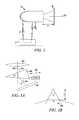
- FIG. 2is a depiction of a housing for supporting the components depicted in FIG. 1 ;
- FIGS. 3A and 3Bare schematic illustrations of focus adjustment of the bar code reader caused by moving a single prism located in the optical path from a focusing lens and a pixel imaging array.
- FIG. 1A block diagram of an imaging-based bar code reader 10 is shown schematically in FIG. 1 .
- the bar code reader 10in addition to imaging and decoding both 1 D and 2 D bar codes and postal codes, is also capable of capturing images and signatures.
- the bar code reader 10is a hand held portable reader components of which are supported within a housing 11 ( FIG. 5 ) that can be carried and used by a user walking or riding through a store, warehouse or plant for reading bar codes for stocking and inventory control purposes.
- An auto-focus reader of the present inventionmay be advantageously used in connection with any type of imaging-based automatic identification system including, but not limited to, bar code readers, signature imaging acquisition and identification systems, optical character recognition systems, fingerprint identification systems and the like. It is the intent of the present invention to encompass all such imaging-based automatic identification systems.
- the bar code reader 10includes a trigger 12 coupled to bar code reader circuitry 13 for initiating reading of a target bar code 15 positioned on an object when the trigger 12 is pulled or pressed.
- the bar code reader 10includes an imaging component 20 including imaging optics 21 and a CCD imager 24 .
- a fixed lens(described in greater detail below) focuses light reflected from the target bar code 15 onto an array of photosensors or pixels 28 of the CCD imager 24 .
- the pixels of pixel array 28are read out generating an analog signal at an output 30 representative of an image of whatever is focused by the lens on the pixel array 28 , for example, an image of the bar code 15 .
- the analog image signal at the output 30is then digitized by an analog-to-digital converter 70 and a digitized signal at an output 74 is decoded by decoder circuitry 80 .
- Decoded data 90representative of the data/information coded in the bar code 15 is then output via a data output port 100 and/or displayed to a user of the reader 10 via a display 108 .
- a speaker 120is activated by the circuitry 13 to indicate to the user that the bar code has been successfully read.
- the reader 10further includes an aiming pattern generator 40 that generates a visible aiming pattern 43 to aid the user in properly aiming the reader at the target bar code 15 .
- the aiming generator 40is a laser aiming apparatus.
- the aiming apparatus 40may utilize an LED or another source of illumination known to those of skill in the art.
- the pattern 43may be a pattern comprising a crosshair formed from a thick horizontal line 43 a and a perpendicular thin vertical line 43 b .
- the laser aiming apparatus 40includes a laser diode 42 and a diffractive lens 44 .
- the reader 10in addition to the aiming pattern generator 40 , the reader 10 includes a separate illumination system 51 for shining illumination light onto the target bar code 15 .
- the CCD or CMOS sensors that make up the imager 24sense light reflected back from the target surface and form pixel data corresponding to an image of the target. It is advantageous to use an array sensor that has the capability to output a portion of pixels upon request, so that the transfer time and processing time can be shortened when only a portion of the array is properly exposed.
- One such sensoris a CMOS array made by Micron having part number MT9M001.
- the pixel data from the arrayis converted into digital data by an A/D converter 70 that is decoded by decoding system 80 .
- An output port or display 108provides the results of decoding to a peripheral device (not shown) or displays them to the user.
- the scanner 10also includes an illumination source (not shown) that is capable, within a prescribed scanner range, of illuminating a portion of the target surface sufficient to fill the entire two-dimensional array of sensors with data.
- the scannerincludes an aiming pattern generator 40 that includes one or more laser diodes 42 and a focusing lens 44 (see FIG. 1 ) that is activated by a user actuated trigger 12 .
- a single prism 150is inserted between an optical system represented by a lens 160 and the imaging array 28 .
- a focus adjustment mechanismprovides a linear shift of the prism as shown by the double headed arrow 170 in FIG. 3A .
- the prismis approximately triangular in plan and is moved back and forth along a path such that an angle at which light enters and exits its entrance and exit surfaces are equal angles 172 , 174 . This is referred to as the angle of least deviation. Under this condition the angular change caused by the prism to an axial ray 162 is given by the equation:
- ⁇is the prism angle (the ‘top corner’ angle, which is the corner shown to the left in FIG. 3A ), n is the index of refraction of the prism material, and n 0 is the index of refraction of air.
- the light path inside of the prism Dis proportional to the amount of prism inserted into the light path, h. This relationship is:
- OPDoptical path difference
- One autofocus processinvolves a determination of the distance from the scanner to the object or target to which the bar code is affixed.
- the laser light emitted by the laser diode 42 that generates the laser aiming pattern 43travels outwardly toward the target bar code 15 .
- the laser beamimpacts the bar code 15 or the object the bar code is affixed to and is reflected back toward the reader where it is focused on the pixel array 28 by the lens 160 .
- Laser rangingutilizes the laser aiming apparatus 40 to determine an object distance u (shown in FIG. 2 ) between a principal plane PP of the lens 160 and the object plane OP, that is, a surface of the target bar code 15 , along the optical axis OA.
- the object distance uis computed using a parallax distance algorithm.
- the image distance vis the distance between the principal plane PP of the lens 22 and a light receiving surface of the pixel array 28 .
- the automatic focusing component 50moves the prism 150 along its path of travel in the direction of the arrow 170 to a suitable position such that a satisfactory image distance (including D, the path through the prism) of the laser aiming pattern 43 is focused onto the pixel array 28 .
- the goal of the auto focusing system 50is to bring the image into focus prior to image capture of the entire bar code.
- a depth of field of the imaging system 20permits a tolerance or imprecision in the range measurement.
- Laser rangingcan also be used with a calibration process wherein the distance to the object is determined and a separation between this distance and a pre-measured or calibrated set of standard distances and prism locations is determined. By finding the closest calibrated object distance the prism is moved to the position corresponding to that distance and acceptable focus obtained.
- the essence of laser rangingis locating the center of the aiming pattern 43 which is located at the intersection of the thick horizontal line 43 a and the thin vertical line 43 b and monitor its movement as the mirror moves.
- the automatic focusing system 50Considering the image of the laser beam is highly blurred when the mirror position produces an out of focus image, it is necessary for the automatic focusing system 50 to identify a region of interest (ROI) of the laser spot, i.e., the region where the aiming pattern 43 lies and its blurred peripheral, and compute the center of mass (COM):
- Xi .times. i*I .function. (i) i .times. I .function. (i), (22) where i indicates the x coordinate of the pixels within the ROI and I(i) their corresponding intensity.
- Y coordinateThe same applies to the Y coordinate.
- So called passive focusingis a technique wherein the object distance is not used to obtain acceptable optical system focus.
- the auto focusing system 50determines a best focus by calculating the contrast of the image. Blurriness reduces contrast so that the best (in focus) image corresponds to the image having the greatest contrast.
- U.S. Pat. No. 6,979,808which is assigned to Canon.
Landscapes
- Physics & Mathematics (AREA)
- Electromagnetism (AREA)
- Engineering & Computer Science (AREA)
- Health & Medical Sciences (AREA)
- General Health & Medical Sciences (AREA)
- Toxicology (AREA)
- Artificial Intelligence (AREA)
- Computer Vision & Pattern Recognition (AREA)
- General Physics & Mathematics (AREA)
- Theoretical Computer Science (AREA)
- Automatic Focus Adjustment (AREA)
Abstract
Description
OPD=(n−n0)ΔD
Claims (21)
Priority Applications (1)
| Application Number | Priority Date | Filing Date | Title |
|---|---|---|---|
| US11/871,194US8028919B2 (en) | 2007-10-12 | 2007-10-12 | Imaging bar code reader with single prism focus adjustment |
Applications Claiming Priority (1)
| Application Number | Priority Date | Filing Date | Title |
|---|---|---|---|
| US11/871,194US8028919B2 (en) | 2007-10-12 | 2007-10-12 | Imaging bar code reader with single prism focus adjustment |
Publications (2)
| Publication Number | Publication Date |
|---|---|
| US20090095815A1 US20090095815A1 (en) | 2009-04-16 |
| US8028919B2true US8028919B2 (en) | 2011-10-04 |
Family
ID=40533229
Family Applications (1)
| Application Number | Title | Priority Date | Filing Date |
|---|---|---|---|
| US11/871,194Active2030-08-03US8028919B2 (en) | 2007-10-12 | 2007-10-12 | Imaging bar code reader with single prism focus adjustment |
Country Status (1)
| Country | Link |
|---|---|
| US (1) | US8028919B2 (en) |
Cited By (3)
| Publication number | Priority date | Publication date | Assignee | Title |
|---|---|---|---|---|
| US20130033617A1 (en)* | 2011-08-05 | 2013-02-07 | Sick Ag | Generating an image presegmented into regions of interest and regions of no interest |
| US10949634B2 (en) | 2005-06-03 | 2021-03-16 | Hand Held Products, Inc. | Apparatus having hybrid monochrome and color image sensor array |
| US11317050B2 (en) | 2005-03-11 | 2022-04-26 | Hand Held Products, Inc. | Image reader comprising CMOS based image sensor array |
Families Citing this family (3)
| Publication number | Priority date | Publication date | Assignee | Title |
|---|---|---|---|---|
| US8210437B2 (en)* | 2010-03-04 | 2012-07-03 | Symbol Technologies, Inc. | Data capture terminal with automatic focusing over a limited range of working distances |
| US8985462B2 (en)* | 2012-12-13 | 2015-03-24 | Symbol Technologies, Inc. | Method of driving focusing element in barcode imaging scanner |
| US10679024B2 (en)* | 2018-07-24 | 2020-06-09 | Cognex Corporation | System and method for auto-focusing a vision system camera on barcodes |
Citations (3)
| Publication number | Priority date | Publication date | Assignee | Title |
|---|---|---|---|---|
| US6766955B2 (en) | 1998-10-19 | 2004-07-27 | Symbol Technologies, Inc. | Optical code reader for producing video displays |
| US6905068B2 (en) | 2003-07-01 | 2005-06-14 | Symbol Technologies, Inc. | Focusing arrangement and method in electro-optical readers |
| US20060038017A1 (en) | 2004-07-30 | 2006-02-23 | Symbol Technologies, Inc. | Automatic focusing system for imaging-based bar code reader |
- 2007
- 2007-10-12USUS11/871,194patent/US8028919B2/enactiveActive
Patent Citations (3)
| Publication number | Priority date | Publication date | Assignee | Title |
|---|---|---|---|---|
| US6766955B2 (en) | 1998-10-19 | 2004-07-27 | Symbol Technologies, Inc. | Optical code reader for producing video displays |
| US6905068B2 (en) | 2003-07-01 | 2005-06-14 | Symbol Technologies, Inc. | Focusing arrangement and method in electro-optical readers |
| US20060038017A1 (en) | 2004-07-30 | 2006-02-23 | Symbol Technologies, Inc. | Automatic focusing system for imaging-based bar code reader |
Cited By (23)
| Publication number | Priority date | Publication date | Assignee | Title |
|---|---|---|---|---|
| US11863897B2 (en) | 2005-03-11 | 2024-01-02 | Hand Held Products, Inc. | Image reader comprising CMOS based image sensor array |
| US12075176B2 (en) | 2005-03-11 | 2024-08-27 | Hand Held Products, Inc. | Image reader comprising CMOS based image sensor array |
| US12185006B2 (en) | 2005-03-11 | 2024-12-31 | Hand Held Products, Inc. | Image reader comprising CMOS based image sensor array |
| US11323649B2 (en) | 2005-03-11 | 2022-05-03 | Hand Held Products, Inc. | Image reader comprising CMOS based image sensor array |
| US11968464B2 (en) | 2005-03-11 | 2024-04-23 | Hand Held Products, Inc. | Image reader comprising CMOS based image sensor array |
| US11317050B2 (en) | 2005-03-11 | 2022-04-26 | Hand Held Products, Inc. | Image reader comprising CMOS based image sensor array |
| US11323650B2 (en) | 2005-03-11 | 2022-05-03 | Hand Held Products, Inc. | Image reader comprising CMOS based image sensor array |
| US12026580B2 (en) | 2005-06-03 | 2024-07-02 | Hand Held Products, Inc. | Apparatus having hybrid monochrome and color image sensor array |
| US12020111B2 (en) | 2005-06-03 | 2024-06-25 | Hand Held Products, Inc. | Apparatus having hybrid monochrome and color image sensor array |
| US11625550B2 (en) | 2005-06-03 | 2023-04-11 | Hand Held Products, Inc. | Apparatus having hybrid monochrome and color image sensor array |
| US12321814B2 (en) | 2005-06-03 | 2025-06-03 | Hand Held Products, Inc. | Apparatus having hybrid monochrome and color image sensor array |
| US11604933B2 (en) | 2005-06-03 | 2023-03-14 | Hand Held Products, Inc. | Apparatus having hybrid monochrome and color image sensor array |
| US11238251B2 (en) | 2005-06-03 | 2022-02-01 | Hand Held Products, Inc. | Apparatus having hybrid monochrome and color image sensor array |
| US11238252B2 (en) | 2005-06-03 | 2022-02-01 | Hand Held Products, Inc. | Apparatus having hybrid monochrome and color image sensor array |
| US12001913B2 (en) | 2005-06-03 | 2024-06-04 | Hand Held Products, Inc. | Apparatus having hybrid monochrome and color image sensor array |
| US12321815B2 (en) | 2005-06-03 | 2025-06-03 | Hand Held Products, Inc. | Apparatus having hybrid monochrome and color image sensor array |
| US12001914B2 (en) | 2005-06-03 | 2024-06-04 | Hand Held Products, Inc. | Apparatus having hybrid monochrome and color image sensor array |
| US12073283B2 (en) | 2005-06-03 | 2024-08-27 | Hand Held Products, Inc. | Apparatus having hybrid monochrome and color image sensor array |
| US10949634B2 (en) | 2005-06-03 | 2021-03-16 | Hand Held Products, Inc. | Apparatus having hybrid monochrome and color image sensor array |
| US12236312B2 (en) | 2005-06-03 | 2025-02-25 | Hand Held Products, Inc. | Apparatus having hybrid monochrome and color image sensor array |
| US12321813B2 (en) | 2005-06-03 | 2025-06-03 | Hand Held Products, Inc. | Apparatus having hybrid monochrome and color image sensor array |
| US20130033617A1 (en)* | 2011-08-05 | 2013-02-07 | Sick Ag | Generating an image presegmented into regions of interest and regions of no interest |
| US9008426B2 (en)* | 2011-08-05 | 2015-04-14 | Sick Ag | Generating an image presegmented into regions of interest and regions of no interest |
Also Published As
| Publication number | Publication date |
|---|---|
| US20090095815A1 (en) | 2009-04-16 |
Similar Documents
| Publication | Publication Date | Title |
|---|---|---|
| US7726573B2 (en) | Compact autofocus bar code reader with moving mirror | |
| US7303131B2 (en) | Automatic focusing system for imaging-based bar code reader | |
| US7967210B2 (en) | Imaging bar code reader having light emitting diode for generating a field of view | |
| US20230100386A1 (en) | Dual-imaging vision system camera, aimer and method for using the same | |
| US7347371B2 (en) | Aiming pattern for imaging-based bar code readers | |
| US8313031B2 (en) | Adaptive aperture for an imaging scanner | |
| US6689998B1 (en) | Apparatus for optical distancing autofocus and imaging and method of using the same | |
| CN106643547B (en) | Light intensity compensation on light providing improved measurement quality | |
| US9076199B2 (en) | System and method for determining and controlling focal distance in a vision system camera | |
| US7762466B2 (en) | Two position zoom lens assembly for an imaging-based bar code reader | |
| US8110790B2 (en) | Large depth of field line scan camera | |
| US7793840B2 (en) | Imaging zoom lens assembly for an imaging-based bar code reader | |
| US20110290886A1 (en) | Imaging bar code reader having variable aperture | |
| US8028919B2 (en) | Imaging bar code reader with single prism focus adjustment | |
| TWI854320B (en) | Miniature long range imaging engine with auto-focus, auto-zoom, and auto-illumination system | |
| EP0516837A1 (en) | Bar code scanner with a large depth of field. | |
| US20070267584A1 (en) | Optical code reader using an anamorphic Scheimpflug optical system | |
| EP4217912B1 (en) | Machine vision system and method with on-axis aimer and distance measurement assembly | |
| US20190188432A1 (en) | Dual-imaging vision system camera and method for using the same | |
| US20100147957A1 (en) | Range finding in imaging reader for electro-optically reading indicia | |
| US6208465B1 (en) | Method and apparatus for imaging an object by diffractive autofocus | |
| EP1193640A2 (en) | An optical data form reading apparatus | |
| US20060118626A1 (en) | Dual laser targeting system | |
| JP2012173124A (en) | Optical information reading device | |
| US7017812B1 (en) | Variable distance angular symbology reader |
Legal Events
| Date | Code | Title | Description |
|---|---|---|---|
| AS | Assignment | Owner name:SYMBOL TECHNOLOGIES, INC., NEW YORK Free format text:ASSIGNMENT OF ASSIGNORS INTEREST;ASSIGNOR:HE, DUANFENG, MR.;REEL/FRAME:019952/0470 Effective date:20071011 | |
| STCF | Information on status: patent grant | Free format text:PATENTED CASE | |
| CC | Certificate of correction | ||
| AS | Assignment | Owner name:MORGAN STANLEY SENIOR FUNDING, INC. AS THE COLLATERAL AGENT, MARYLAND Free format text:SECURITY AGREEMENT;ASSIGNORS:ZIH CORP.;LASER BAND, LLC;ZEBRA ENTERPRISE SOLUTIONS CORP.;AND OTHERS;REEL/FRAME:034114/0270 Effective date:20141027 Owner name:MORGAN STANLEY SENIOR FUNDING, INC. AS THE COLLATE Free format text:SECURITY AGREEMENT;ASSIGNORS:ZIH CORP.;LASER BAND, LLC;ZEBRA ENTERPRISE SOLUTIONS CORP.;AND OTHERS;REEL/FRAME:034114/0270 Effective date:20141027 | |
| FPAY | Fee payment | Year of fee payment:4 | |
| AS | Assignment | Owner name:SYMBOL TECHNOLOGIES, LLC, NEW YORK Free format text:CHANGE OF NAME;ASSIGNOR:SYMBOL TECHNOLOGIES, INC.;REEL/FRAME:036083/0640 Effective date:20150410 | |
| AS | Assignment | Owner name:SYMBOL TECHNOLOGIES, INC., NEW YORK Free format text:RELEASE BY SECURED PARTY;ASSIGNOR:MORGAN STANLEY SENIOR FUNDING, INC.;REEL/FRAME:036371/0738 Effective date:20150721 | |
| MAFP | Maintenance fee payment | Free format text:PAYMENT OF MAINTENANCE FEE, 8TH YEAR, LARGE ENTITY (ORIGINAL EVENT CODE: M1552); ENTITY STATUS OF PATENT OWNER: LARGE ENTITY Year of fee payment:8 | |
| MAFP | Maintenance fee payment | Free format text:PAYMENT OF MAINTENANCE FEE, 12TH YEAR, LARGE ENTITY (ORIGINAL EVENT CODE: M1553); ENTITY STATUS OF PATENT OWNER: LARGE ENTITY Year of fee payment:12 |