US8028688B2 - Concrete block splitting and pitching apparatus and method - Google Patents
Concrete block splitting and pitching apparatus and methodDownload PDFInfo
- Publication number
- US8028688B2 US8028688B2US11/583,592US58359206AUS8028688B2US 8028688 B2US8028688 B2US 8028688B2US 58359206 AUS58359206 AUS 58359206AUS 8028688 B2US8028688 B2US 8028688B2
- Authority
- US
- United States
- Prior art keywords
- pitching
- blade
- concrete block
- edge
- splitting
- Prior art date
- Legal status (The legal status is an assumption and is not a legal conclusion. Google has not performed a legal analysis and makes no representation as to the accuracy of the status listed.)
- Expired - Fee Related
Links
Images


Classifications
- B—PERFORMING OPERATIONS; TRANSPORTING
- B28—WORKING CEMENT, CLAY, OR STONE
- B28D—WORKING STONE OR STONE-LIKE MATERIALS
- B28D1/00—Working stone or stone-like materials, e.g. brick, concrete or glass, not provided for elsewhere; Machines, devices, tools therefor
- B28D1/22—Working stone or stone-like materials, e.g. brick, concrete or glass, not provided for elsewhere; Machines, devices, tools therefor by cutting, e.g. incising
- B28D1/222—Working stone or stone-like materials, e.g. brick, concrete or glass, not provided for elsewhere; Machines, devices, tools therefor by cutting, e.g. incising by pressing, e.g. presses
- Y—GENERAL TAGGING OF NEW TECHNOLOGICAL DEVELOPMENTS; GENERAL TAGGING OF CROSS-SECTIONAL TECHNOLOGIES SPANNING OVER SEVERAL SECTIONS OF THE IPC; TECHNICAL SUBJECTS COVERED BY FORMER USPC CROSS-REFERENCE ART COLLECTIONS [XRACs] AND DIGESTS
- Y10—TECHNICAL SUBJECTS COVERED BY FORMER USPC
- Y10T—TECHNICAL SUBJECTS COVERED BY FORMER US CLASSIFICATION
- Y10T225/00—Severing by tearing or breaking
- Y10T225/30—Breaking or tearing apparatus
- Y10T225/371—Movable breaking tool
- Y10T225/379—Breaking tool intermediate spaced work supports
Definitions
- the present inventionpertains to the field of concrete block manufacturing, and more specifically to a concrete block splitting and pitching apparatus and method for splitting a concrete block into two or more sections and pitching the edges of the sections in a single step.
- Prior art systems and methods for manufacturing concrete blockshave included splitting devices that use two or more diametrically-opposed blades in a press, where the blades cause the concrete block to split into two parts.
- Some of the prior art concrete block splittersfurther include ridges or projections to create random variations on the concrete block, so as to manufacture a plurality of blocks that do not appear to be identical, to simulate a hand-made or naturally-occurring block.
- prior art systems and methodshave included pitching devices that pitch the edges of a concrete block. These pitching devices are also used to create random variations to simulate hand-made or naturally-occurring block. As such, the prior art concrete block manufacturing systems and methods teach away from creation of features on a concrete block in a controlled manner.
- a concrete block splitting and pitching apparatus and methodare provided that allow a concrete block to be split and pitched in a single step.
- a system and method for splitting and pitching a concrete blockare provided that allow the pitching of the concrete block to be controlled so as to create controlled features on the pitched surface.
- an apparatus for splitting a concrete block and pitching at least one edge of the split concrete blockincludes a splitting blade have a blade edge, such as a sharpened edge or a dull edge.
- the splitting bladeis configured to move in a first direction so as to split a concrete block into two or more sections.
- the apparatusalso includes a pitching blade having a blade edge, such as a sharpened and adjacent to the splitting blade, the pitching blade edge vertically offset from the splitting blade edge so as to pitch an edge of one of the sections of the concrete block after the concrete block has been split.
- the present inventionprovides many important technical advantages.
- One important technical advantage of the present inventionis an apparatus and method for splitting and pitching a concrete block that allows the concrete block to be split and pitched in a single step, so as to create a pitched surface having reduced random variations.
- FIG. 1is a diagram of an edge view of a blade assembly in accordance with an exemplary embodiment of the present invention
- FIG. 2is a diagram of a side view of a blade assembly in accordance with an exemplary embodiment of the present invention
- FIG. 3is a diagram of an edge view of a blade assembly with parallel staggered blades in accordance with an exemplary embodiment of the present invention
- FIG. 4is a diagram of a side view of a blade assembly with parallel and axially staggered blades in accordance with an exemplary embodiment of the present invention
- FIG. 5is a diagram of a side view of a blade assembly with aligned parallel blades in accordance with an exemplary embodiment of the present invention
- FIG. 6is a diagram of a blade assembly with vertically staggered blades in accordance with an exemplary embodiment of the present invention
- FIG. 7is a diagram of a pitching blade with a crown in accordance with an exemplary embodiment of the present invention.
- FIG. 8is a diagram of a pitching blade with cornered edges in accordance with an exemplary embodiment of the present invention.
- FIG. 9is a diagram of a concrete block in accordance with an exemplary embodiment of the present invention.
- FIG. 10is a diagram of a press in accordance with an exemplary embodiment of the present invention.
- FIG. 11is a diagram of a concrete block in accordance with an exemplary embodiment of the present invention.
- FIG. 12is a diagram of a concrete block in accordance with an exemplary embodiment of the present invention.
- FIG. 13is a diagram of a pitching blade assembly in accordance with an exemplary embodiment of the present invention.
- FIG. 14is a diagram of a pitching blade assembly adjusting to a surface irregularity in accordance with an exemplary embodiment of the present invention.
- FIG. 1is a diagram of an edge view of a blade assembly 100 in accordance with an exemplary embodiment of the present invention.
- Blade assembly 100allows a block, such as one formed from concrete, masonry, or other suitable materials (all hereinafter referred to in general as a concrete block) to be split and pitched in a single step, as opposed to requiring multiple steps and stations for splitting and pitching.
- Blade assembly 100includes splitting blade 102 and pitching blades 104 and 106 .
- Each of splitting blade 102 and pitching blades 104 and 106are secured in grooves 112 , 114 and 110 , respectively, of blade holder 108 , which can be an interchangeable blade holder assembly, a static blade holder assembly that is part of a larger cutting machine, or other suitable blade assemblies.
- pins, screws, clamps, or other suitable devices or materialscan be used to secure splitting blade 102 in groove 112 and pitching blades 104 and 106 in grooves 114 and 110 , respectively.
- the shape of splitting blade 102 and pitching blades 104 and 106can likewise be altered, such as to interlock with grooves 112 , 114 and 116 , respectively, or for other suitable purposes.
- Splitting blade 102 and pitching blades 104 and 106are made from suitable material for splitting concrete blocks, such as steel or other suitable blade material.
- Pitching blades 104 and 106are inset a distance “X 1 ” and “X 2 ,” respectively, from splitting blade 102 , such that when blade holder 108 is moved towards the concrete block to be split and pitched, splitting blade 102 encounters the concrete block first and causes the block to split.
- Pitching blades 104 and 106then encounter the block after it has been split so as to cause the split edge of the block to be pitched.
- splitting blade 102can be used to affect the action of pitching blades 104 and 106 , such as by increasing the height difference “X 1 ” and “X 2 ” so that splitting blade 102 applies a force against the split face of the concrete block.
- the spacings “X 1 ,” “X 2 ,” “Y 1 ” and “Y 2 ” as showncan be varied as suitable to create different pitch depths, spacing, to decrease the amount of force required to perform the pitching and splitting operations, to control the quality of the pitching and splitting operations so as to reduce random variations in the split or pitched surfaces, or for other suitable purposes.
- Splitting blade 102 and pitching blades 104 and 106can be removed to allow them to be replaced, such as to modify the height difference “X 1 ” or “X 2 ,” the spacing “Y 1 ” or “Y 2 ,” to replaced blades after they have been damaged or worn, or for other suitable purposes.
- Further variations of exemplary pitching blades 104 and 106are shown in side view in FIGS. 2 , 5 , 6 from the view as shown in FIG. 1 .
- blade assembly 100is used in conjunction with other blade assemblies to split a concrete block and to pitch the resulting edges in a single combined splitting and pitching operation.
- the separation “Y 1 ” and “Y 2 ” between the plane of splitting blade 102 and the planes of pitching blades 104 and 106 , respectively, and “X 1 ” and “X 2 ” between the edge of splitting blade 102 and between the edge of pitching blades 104 and 106 , respectively,can be varied to control the quality of the pitched edge that is formed after splitting.
- the width of splitting blade 102can be controlled so as to separate the segments of the split concrete block so as to prevent interference between the segments as they are split, which can create random variations that might not be desired.
- Other suitable variations described hereincan also or alternatively be used to control the pitching of edges after splitting.
- FIG. 2is a diagram of a side view of blade assembly 200 in accordance with an exemplary embodiment of the present invention.
- Blade assembly 200includes splitting blade 102 and pitching blade 104 .
- Splitting blade 102 and pitching blade 104are held by blade holder 108 .
- the offset “X 1 ” between splitting blade 102 and pitching blade 104is shown in FIG. 2 .
- blade assembly 200is moved towards a concrete block in the direction of the arrow to split the concrete block and to pitch the edges of the concrete block in a single step.
- blade assembly 200can be part of a hydraulic, pneumatic, electric or mechanical press that simultaneously moves blade assembly 200 down onto the concrete block to be split, two other blade assemblies sideways against the concrete block, and one additional blade assembly upwards against the concrete block.
- blade assembly 200is used for each blade assembly, each edge of the two block pieces that are formed from the concrete block that is being split can be pitched.
- the pitched surface created using blade assembly 200can be controlled to have predetermined characteristics based on the orientation of splitting blade 102 and pitching blade 104 , such as by increasing the planar separation “Y 2 ” or the edge height separation “X 1 ” as shown in FIG. 1 .
- FIG. 3is a diagram of an edge view of blade assembly 300 with parallel staggered blades in accordance with an exemplary embodiment of the present invention.
- Blade assembly 300includes splitting blade 302 and pitching blades 304 , 306 , 308 and 310 , 312 , and 314 . Each of the splitting and pitching blades are held by blade holder 316 in corresponding slots. As shown, pitching blades 304 , 306 , 308 and pitching blades 310 , 312 , and 314 are parallel to and staggered from each other so as to create a staggered pitching effect.
- a side view of the arrangement of splitting blade 302 and pitching blades 304 , 306 , and 308is shown in FIG. 4 .
- pitching blades 304 , 306 , 308 and pitching blades 310 , 312 , and 314are separated from splitting blade 302 by a distance of Y 4 , Y 5 , Y 6 , Y 1 , Y 2 and Y 3 , respectively, and the cutting edge of pitching blades 304 , 306 , 308 and pitching blades 310 , 312 , and 314 are separated from the cutting edge of splitting blade 302 by a distance of X 4 , X 5 , X 6 , X 1 , X 2 and X 3 , respectively.
- the separation between the pitching blades and the splitting bladecan be controlled so as to reduce the amount of force required to split and pitch the concrete block, to control the pitching of the concrete block edges after splitting so as to eliminate unwanted random variations, and for other suitable purposes.
- FIG. 4is a diagram of a side view of blade assembly 400 with parallel and axially staggered blades in accordance with an exemplary embodiment of the present invention.
- Blade assembly 400includes splitting blade 302 and pitching blades 304 , 306 and 308 , each of which is held by blade holder 316 .
- pitching blade 304is parallel to and axially offset from splitting blade 302 by a different amount than the axial offset of pitching blades 306 and 308 , which are also parallel to splitting blade 302 .
- an axially-scalloped pitching effectcan be created on each block that is split and pitched using blade assembly 400 .
- FIG. 5is a diagram of a side view of blade assembly 500 with aligned parallel blades in accordance with an exemplary embodiment of the present invention.
- Blade assembly 500includes splitting blade 102 , pitching blades 104 , and blade holder 108 .
- the pitching blades of blade assembly 500are not axially offset but lie alongside the same horizontal axis. In this manner, the pitching cuts made by pitching blades 104 do not form an axially-scalloped pitching effect, and the scalloped pitching effect created by blade assembly 500 might result in some random variations that cause concrete blocks created using blade assembly 500 to contain certain desired random variations while retaining a scalloped effect.
- FIG. 6is a diagram of blade assembly 600 with vertically staggered blades in accordance with an exemplary embodiment of the present invention.
- Blade assembly 600includes splitting blade 102 and pitching blades 104 , 104 ′ and 104 ′′, each of which are held by blade holder 108 .
- FIG. 6shows these vertical variations, which can be used to create a controlled and axially-aligned scalloped pitching effect on the edges of a concrete block after it has been split by splitting blade 102 of blade assembly 600 .
- the amount of force required to split and pitch the concrete blockcan be decreased, such as where it is desirable to reduce the amount of force that is required to split and pitch concrete blocks in order to meet machine press design loading, to conserve power, or for other suitable purposes.
- FIG. 7is a diagram of pitching blade 700 with a crown in accordance with an exemplary embodiment of the present invention.
- Pitching blade 700includes crown 702 that rises to a peak in the center of pitching blade 700 . In this manner, the force required to pitch the block being operated on is decreased by focusing the force at the maximum height of crown 702 .
- Pitching blade 700also helps to reduce random variations that can result from a flat pitching blade, where the pitching action can start unevenly at various points along the length of the flat pitching blade.
- FIG. 8is a diagram of pitching blade 800 with cornered edges in accordance with an exemplary embodiment of the present invention.
- Pitching blade 800includes cornered edges 802 and 804 .
- providing a corner on cornered edges 802 and 804can help to prevent cracking or other unintended effects on the concrete block section that has been split, which can create random variations in the appearance of the pitched surface.
- FIG. 9is a diagram of concrete block 900 in accordance with an exemplary embodiment of the present invention.
- Concrete block 900is shown being split into two sections, 902 and 904 .
- Splitting blades 906 A and 906 Bare used to split concrete block 900 into sections 902 and 904 by impacting with the block before pitching blades 908 A, 908 B, 910 A and 910 B.
- pitching blades 908 A and 908 B on one side of the split and pitching blades 910 A and 910 B on the opposite side of the splitinteract with the block so as to pitch the edges of sections 902 and 904 at the split, shown as pitch break in FIG. 9 .
- Two additional sets of splitting and pitching bladescan also be used that move perpendicular to the direction of motion shown in FIG. 9 . In this manner, a split concrete block having a pitched edge can be created in a single step.
- the spacing of splitting blades 906 A and 906 B relative to pitching blades 908 A, 908 B, 910 A and 910 Bcan also be varied so as to control the location of the pitch break.
- the splitting bladeswill provide an axial force to the split face of each concrete block section that will cause the pitch break to elongate as shown.
- Even a slight difference in height between the splitting blades and the pitching bladeswill affect the dimensions of the pitch break, making the dimensions more controlled due only to the presence of pitching blades adjacent to the splitting blades and the presence of the newly-split concrete block sections adjacent to each other.
- the dimensions of the pitch breakare controlled not only by the pitching blades but also by the configuration of all of the blades in the blade assembly as well as the combined splitting and pitching operation that leaves the split concrete block sections adjacent to each other during the pitching operation.
- FIG. 10is a diagram of press 1000 in accordance with an exemplary embodiment of the present invention.
- Press 1000includes base 1002 which contains splitting blade 1004 and pitching blade 1006 .
- blade holder 1008holds a corresponding splitting blade 1012 and pitching blade 1010 .
- blade holder 1014holds pitching blade 1016 and splitting blade 1018 and blade holder 1020 holds pitching blade 1022 and splitting blade 1024 .
- other suitable blade configurationssuch as those shown herein or other suitable variations described herein, can also or alternatively be used.
- blade holder 1008is moved downwards, such as by a pneumatic press or other suitable presses capable of providing sufficient force to split concrete block 1026 .
- base 1002can be recessed so as to hold concrete block 1026 up and can include movable splitting blade 1004 and pitching blade 1006 that can be raised, such as by a pneumatic press, in coordination with splitting blade 1012 and pitching blade 1010 .
- splitting blades 1012 and 1004interact with concrete block 1026 so as to create a split through concrete block 1026 .
- blade holders 1014 and 1020are moved laterally so as to cause splitting blades 1018 and 1024 to interact with concrete block 1026 at the same time that splitting blades 1012 and 1004 interact with concrete block 1026 so to form a uniform split through concrete block 1026 .
- pitching blades 1006 , 1010 , 1016 , and 1022interact with concrete block 1026 so as to pitch the edges of concrete block 1026 along the split. In this manner, concrete block 1026 can be split into two blocks and the edges of each block can be pitched in a single action.
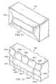
- FIG. 11is a diagram of concrete block 1100 in accordance with an exemplary embodiment of the present invention.
- Concrete block 1100includes pitched area 1102 and split face 1104 .
- Pitched area 1102is formed by pitching blades that are uniform along the length and sides of the splitting assembly.
- Split face 1104is formed by splitting blades that are diametrically opposed to each other.
- FIG. 12is a diagram of concrete block 1200 in accordance with an exemplary embodiment of the present invention.
- Concrete block 1200includes scalloped sections 1202 A through 1202 L and split face 1204 .
- multiple pitching bladescan be used to form scalloped sections 1202 A through 1202 L.
- scalloped sections 1202 A through 1202 Lcan be overlapped, or by aligning them and staggering the action of pitching blades by having different pitching blade heights, the scalloped sections can also be overlapped, uniform or can have other desired configurations.
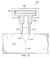
- FIG. 13is a diagram of a pitching blade assembly 1300 in accordance with an exemplary embodiment of the present invention.
- Pitching blade assembly 1300includes press 1302 , compressible material 1304 and blade holder assembly 1306 .
- Blade holder assembly 1306includes two pitching blades 1308 and 1310 , separated by a distance “X.” If the distance “X” is less than the distance beyond which pitching blades 1308 and 1310 will operate as separate splitting blades, then pitch breaks 1314 and 1316 will form in concrete block 1312 , and will propagate together to form split break 1318 .
- the maximum separation distancewill be a function of the material characteristics and dimensions of
- FIG. 14is a diagram of a pitching blade assembly 1400 adjusting to a surface irregularity in accordance with an exemplary embodiment of the present invention.
- concrete block 1312includes surface irregularity 1402 , which causes pitching blades 1308 and 1310 to conform to the surface of concrete block 1312 .
- Compressible material 1304allows blade holder assembly 1306 to shift, so as to allow pitching blades 1308 and 1310 to conform to surface irregularity 1402 of concrete block 1312 , which avoids improper propagation of pitch breaks 1314 and 1316 .
Landscapes
- Engineering & Computer Science (AREA)
- Mining & Mineral Resources (AREA)
- Mechanical Engineering (AREA)
- Processing Of Stones Or Stones Resemblance Materials (AREA)
Abstract
Description
Claims (20)
Priority Applications (1)
| Application Number | Priority Date | Filing Date | Title |
|---|---|---|---|
| US11/583,592US8028688B2 (en) | 2006-10-18 | 2006-10-18 | Concrete block splitting and pitching apparatus and method |
Applications Claiming Priority (1)
| Application Number | Priority Date | Filing Date | Title |
|---|---|---|---|
| US11/583,592US8028688B2 (en) | 2006-10-18 | 2006-10-18 | Concrete block splitting and pitching apparatus and method |
Publications (2)
| Publication Number | Publication Date |
|---|---|
| US20080096471A1 US20080096471A1 (en) | 2008-04-24 |
| US8028688B2true US8028688B2 (en) | 2011-10-04 |
Family
ID=39318505
Family Applications (1)
| Application Number | Title | Priority Date | Filing Date |
|---|---|---|---|
| US11/583,592Expired - Fee RelatedUS8028688B2 (en) | 2006-10-18 | 2006-10-18 | Concrete block splitting and pitching apparatus and method |
Country Status (1)
| Country | Link |
|---|---|
| US (1) | US8028688B2 (en) |
Cited By (5)
| Publication number | Priority date | Publication date | Assignee | Title |
|---|---|---|---|---|
| US9102079B2 (en) | 2002-03-20 | 2015-08-11 | Anchor Wall Systems, Inc. | Block splitting assembly and method |
| US20150364905A1 (en)* | 2014-06-11 | 2015-12-17 | Ted Russell Fehrman | Conduit fitting splitter |
| US9399310B2 (en) | 2013-06-28 | 2016-07-26 | D. L. Cetrangolo | Method for producing thin rock-faced veneers from granitic stone slabs |
| USD887024S1 (en) | 2015-10-21 | 2020-06-09 | Pavestone, LLC | Interlocking paver |
| USD1037491S1 (en) | 2021-12-14 | 2024-07-30 | Pavestone, LLC | Wall block |
Families Citing this family (8)
| Publication number | Priority date | Publication date | Assignee | Title |
|---|---|---|---|---|
| US7766002B2 (en)* | 2006-10-18 | 2010-08-03 | Pavestone Company, L.P. | Concrete block splitting and pitching apparatus |
| US8763599B2 (en)* | 2006-10-18 | 2014-07-01 | Pavestone, LLC | Masonry block multi-splitting apparatus and method |
| MX2009012799A (en) | 2007-06-06 | 2009-12-10 | Keystone Retaining Wall System | Block splitter assembly and method of producing wall blocks. |
| US10583588B2 (en) | 2013-06-21 | 2020-03-10 | Pavestone, LLC | Manufactured retaining wall block with improved false joint |
| US20140377016A1 (en) | 2013-06-21 | 2014-12-25 | Pavestone, LLC | Retaining wall block system with modulating heights, widths, and included angles |
| USD737468S1 (en) | 2014-05-07 | 2015-08-25 | Pavestone, LLC | Front face of a retaining wall block |
| CA2927283C (en) | 2015-04-20 | 2020-12-08 | Keystone Retaining Wall Systems Llc | Block splitter assembly and method of producing wall blocks |
| US9943983B2 (en)* | 2015-09-15 | 2018-04-17 | Keystone Retaining Wall Systems Llc | Block splitter assembly and method of producing wall blocks |
Citations (117)
| Publication number | Priority date | Publication date | Assignee | Title |
|---|---|---|---|---|
| US415773A (en) | 1889-11-26 | Brick | ||
| US470788A (en)* | 1892-03-15 | Tool for cutting and dressing stone | ||
| US511098A (en) | 1893-12-19 | Brick-mold | ||
| US534462A (en) | 1895-02-19 | Building-brick | ||
| US787199A (en) | 1904-11-10 | 1905-04-11 | David W Lloyd | Method of manufacturing building-blocks. |
| US803014A (en) | 1905-04-11 | 1905-10-31 | David Mcilravy | Machine for producing artificial stone. |
| US806951A (en) | 1905-08-04 | 1905-12-12 | James E W Bryning | Gang-saw. |
| US1086975A (en) | 1913-02-20 | 1914-02-10 | Frank Aaronson | Building-block and method of forming the same. |
| US1092621A (en) | 1911-05-17 | 1914-04-07 | Frederick A Bach | Shaped or molded block for making ceilings. |
| US1272533A (en)* | 1916-10-09 | 1918-07-16 | William B Robinson | Brick-scoring mechanism. |
| US1287055A (en) | 1918-03-15 | 1918-12-10 | Arthur H Lehman | Building-block machine. |
| US1534353A (en) | 1923-04-19 | 1925-04-21 | Besser Herman | Fractured block and method of making the same |
| US1872522A (en) | 1930-10-02 | 1932-08-16 | W A Riddell Company | Method of making artificial stone brick |
| US1893430A (en) | 1930-01-06 | 1933-01-03 | Donald A Mckenzie | Building unit and method of making the same |
| US2203935A (en) | 1936-11-06 | 1940-06-11 | Siemens Ag | Telephone system |
| US2219606A (en) | 1939-03-13 | 1940-10-29 | Chicago Retort & Fire Brick Co | Firebrick and method of making same |
| US2313363A (en) | 1940-07-02 | 1943-03-09 | George H Schmitt | Retaining wall and block for the same |
| US2319154A (en)* | 1940-01-08 | 1943-05-11 | Ernest M Orlow | Apparatus and method for breaking slabs of stone |
| US2593606A (en) | 1950-02-21 | 1952-04-22 | Orville E Gibson | Block-bisecting machine |
| US2657681A (en) | 1952-01-03 | 1953-11-03 | Gatzke Charles | Machine for splitting concrete blocks, building stones, and the like |
| US2746447A (en) | 1953-12-28 | 1956-05-22 | Petch Mfg Company | Block splitting machine |
| US2775326A (en) | 1952-10-23 | 1956-12-25 | Scully Jones & Co | Torque drivers |
| US2867205A (en) | 1957-01-22 | 1959-01-06 | George A Vesper | Stone splitting machine |
| US2881753A (en)* | 1955-07-26 | 1959-04-14 | Gerhard B Entz | Machines for cutting or splitting concrete blocks and the like |
| US2925080A (en) | 1958-07-10 | 1960-02-16 | Texas Industries Inc | Apparatus for splitting blocks |
| GB924290A (en) | 1960-12-27 | 1963-04-24 | Jaroslav Karfus | Hydraulic splitting machine for cutting slabs, blocks and pieces for mosaics |
| US3095868A (en) | 1961-05-24 | 1963-07-02 | Elmer F Mangis | Stone facing machine cutter head |
| GB948121A (en) | 1962-08-30 | 1964-01-29 | Vni Sky I Novykh Str Nykh Mate | A stone cutting machine |
| US3120842A (en) | 1961-03-15 | 1964-02-11 | Harold L Cox | Equalizer for shear |
| US3392719A (en) | 1965-06-03 | 1968-07-16 | Clanton | Machine for splitting concrete blocks |
| US3425105A (en) | 1965-09-23 | 1969-02-04 | Gulde Cement Co | Apparatus for making concrete facing bricks with varied color and texture |
| US3492984A (en) | 1967-09-18 | 1970-02-03 | R H Semon | Cell block splitting machine |
| US3559631A (en) | 1968-07-12 | 1971-02-02 | E & R Mfg Co Inc | Hydraulic masonry cutting machine |
| US3677258A (en)* | 1970-04-24 | 1972-07-18 | Fletcher Co H E | Apparatus for continuously gauging and cutting stone in a guillotine type cutting machine |
| US3809049A (en)* | 1971-12-01 | 1974-05-07 | Fletcher H Co | Apparatus for cutting rough-surfaced stone bodies |
| US3940229A (en) | 1974-02-22 | 1976-02-24 | Columbia Machine, Inc. | Apparatus for manufacturing rough faced bricks |
| US3981953A (en) | 1973-04-07 | 1976-09-21 | Donald John Haines | Method for casting blocks having fractured face |
| US4023767A (en) | 1976-06-15 | 1977-05-17 | Fontana Joseph R | Mold box and mold head |
| US4050864A (en) | 1975-09-03 | 1977-09-27 | Saiji Komaki | Apparatus for manufacturing concrete panels with surface pattern decorations |
| GB1509747A (en) | 1974-05-22 | 1978-05-04 | Juul H | Method of and apparatus for cleaving building slabs |
| US4098865A (en) | 1976-01-26 | 1978-07-04 | Hanover Prest-Paving Co. | Methods of making paving block |
| US4114773A (en) | 1976-08-12 | 1978-09-19 | Katsura Machine Co., Ltd. | Feeding device of a concrete block splitting apparatus |
| US4139593A (en) | 1977-08-05 | 1979-02-13 | Mid-Iowa Concrete Products Company | Method and apparatus for making molded articles |
| US4178340A (en) | 1978-06-26 | 1979-12-11 | A B C Concrete Products | Method and apparatus for making concrete brick having antique appearance |
| US4193718A (en) | 1977-07-11 | 1980-03-18 | Sf-Vollverbundstein-Kooperation Gmbh | Earth retaining wall of vertically stacked chevron shaped concrete blocks |
| US4250863A (en) | 1979-11-26 | 1981-02-17 | Pierre Gagnon | Cement block splitter |
| US4335549A (en) | 1980-12-01 | 1982-06-22 | Designer Blocks, Inc. | Method, building structure and side-split block therefore |
| US4391312A (en)* | 1981-06-01 | 1983-07-05 | Sakraida Jr Gerard J | Log splitting head |
| US4524551A (en) | 1981-03-10 | 1985-06-25 | Rolf Scheiwiller | Construction units for the erection of walls and method of utilization |
| US4599929A (en)* | 1983-05-27 | 1986-07-15 | Hans Dutina Ab | Method of guiding saw blades and device for carrying out the method |
| US4627764A (en) | 1981-03-25 | 1986-12-09 | Rolf Scheiwiller | Paving stone, process for manufacturing same and device for carrying out the manufacturing process |
| US4770218A (en) | 1988-01-22 | 1988-09-13 | Dennis Duerr | Block stripper and stroke stop for wood splitters |
| US4782866A (en)* | 1988-01-19 | 1988-11-08 | Charlie Valdez | Log splitting head |
| US4784821A (en) | 1986-06-30 | 1988-11-15 | Dory Leopold | Method for manufacturing a building block imitating a pile of dry stones |
| USD299067S (en) | 1987-04-02 | 1988-12-20 | Keystone Retaining Wall Systems, Inc. | Modular block wall |
| US4802836A (en) | 1987-07-13 | 1989-02-07 | Gilles Whissell | Compaction device for concrete block molding machine |
| US4834155A (en)* | 1986-05-02 | 1989-05-30 | Martti Vuollet | Chipper |
| US4848309A (en) | 1988-07-25 | 1989-07-18 | Johnny Alderete | Masonry punch |
| US4869660A (en) | 1987-06-05 | 1989-09-26 | Willi Ruckstuhl | Apparatus for fabrication of concrete brick |
| US4973192A (en) | 1990-03-22 | 1990-11-27 | Hair Roberta A | Interlocking paving stone and ground cover formed thereof |
| USD315026S (en) | 1989-06-01 | 1991-02-26 | Groupe Permacon Inc. | Molded curb-stone |
| US5017049A (en) | 1990-03-15 | 1991-05-21 | Block Systems Inc. | Composite masonry block |
| US5028172A (en) | 1986-01-15 | 1991-07-02 | Tensa-Crete Inc. | Retaining wall structure |
| US5031376A (en) | 1988-02-25 | 1991-07-16 | Bender Eugene M | Retaining wall construction and blocks therefore |
| US5056998A (en) | 1987-07-08 | 1991-10-15 | Koninklijke Mosa B.V. | Apparatus for producing a set of mutually distinguishable flooring tiles |
| US5066070A (en) | 1988-02-10 | 1991-11-19 | Clarke Ronald A W | Apparatus for reflex-percussive cutting of concrete etc. |
| US5078940A (en) | 1990-05-31 | 1992-01-07 | Sayles Jerome D | Method for forming an irregular surface block |
| US5107911A (en)* | 1991-05-06 | 1992-04-28 | Plakotaris Vincent A | Log splitting device |
| US5139006A (en)* | 1989-04-03 | 1992-08-18 | Trudeau Leon B | Hydraulic concrete pile cutter |
| US5152275A (en) | 1990-02-17 | 1992-10-06 | Almi Machinefabriek B.V. | Stone splitter |
| US5158132A (en) | 1989-03-20 | 1992-10-27 | Gerard Guillemot | Zone-regulated high-temperature electric-heating system for the manufacture of products made from composite materials |
| US5217630A (en) | 1990-05-31 | 1993-06-08 | Sayles Jerome D | Apparatus for forming an irregular surface block |
| US5441092A (en)* | 1992-07-07 | 1995-08-15 | Randle; Hale | Method and apparatus for the production of heart centered, substantially square timbers |
| US5487526A (en) | 1992-06-16 | 1996-01-30 | Hupp; Jack T. | Mold device for forming concrete pathways |
| US5534214A (en) | 1992-03-24 | 1996-07-09 | Toyoko Giken Co., Ltd. | Process for coloring concrete |
| USD377181S (en) | 1996-03-14 | 1997-01-07 | Hupp Jack T | Mold for forming concrete cobblestones |
| USD378702S (en) | 1995-08-09 | 1997-04-01 | Handy-Stone Corporation | Edging block |
| US5662386A (en) | 1995-10-31 | 1997-09-02 | Newman; Christopher M. | Plunger-actuated surface-treating devices |
| US5662094A (en) | 1996-07-03 | 1997-09-02 | Giacomelli; Angelo J. | Guillotine cutting apparatus for bricks, building blocks and the like |
| US5687515A (en) | 1995-06-15 | 1997-11-18 | Rodrigues; Robert Wallace | Monument display case and mounting assembly |
| US5709062A (en) | 1992-10-06 | 1998-01-20 | Anchor Wall Systems, Inc. | Composite masonry block |
| US5722386A (en) | 1994-12-07 | 1998-03-03 | Pacific International Tool & Shear, Ltd. | Method and apparatus for forming ornamental edges on cement siding |
| US5733470A (en) | 1993-09-24 | 1998-03-31 | Siroflex Of America, Inc. | Mold for casting ground covering |
| US5735643A (en) | 1995-02-24 | 1998-04-07 | Groupe Permacon Inc. | Retaining wall system |
| US5762061A (en) | 1993-06-18 | 1998-06-09 | Bevan; David Maurice | Splitting apparatus |
| US5788423A (en) | 1995-09-08 | 1998-08-04 | G.P. Industries, Inc. | Masonry block retaining wall with attached keylock facing panels and method of constructing the same |
| US5791389A (en)* | 1997-03-28 | 1998-08-11 | Yvonne Company | Apparatus and method for forming firewood logs |
| US5827015A (en) | 1989-09-28 | 1998-10-27 | Anchor Wall Systems, Inc. | Composite masonry block |
| USD404146S (en) | 1995-07-19 | 1999-01-12 | G. P. Industries, Inc. | Combined keylock facing panel and H-shaped retaining wall block |
| US5879603A (en) | 1996-11-08 | 1999-03-09 | Anchor Wall Systems, Inc. | Process for producing masonry block with roughened surface |
| US5884445A (en) | 1997-12-02 | 1999-03-23 | Oldcastle, Inc. | Paving block array |
| US6029943A (en) | 1996-11-08 | 2000-02-29 | Anchor Wall Systems, Inc. | Splitting technique |
| US6082057A (en) | 1996-11-08 | 2000-07-04 | Anchor Wall Systems, Inc. | Splitting technique |
| US6102026A (en) | 1998-12-30 | 2000-08-15 | Pacific International Tool & Shear, Ltd. | Fiber-cement cutting tools and methods for cutting fiber-cement materials, such as siding |
| US6113379A (en) | 1998-07-02 | 2000-09-05 | Anchor Wall Systems, Inc. | Process for producing masonry block with roughened surface |
| US6149352A (en) | 1999-02-11 | 2000-11-21 | Keystone Retaining Wall Systems, Inc. | Retaining wall block system |
| USD438640S1 (en) | 1999-08-17 | 2001-03-06 | Anchor Wall Systems, Inc. | Face of a retaining wall block |
| US6199545B1 (en)* | 1999-04-19 | 2001-03-13 | Darrel M. Adamson | Engraving apparatus and method |
| US6209848B1 (en) | 1999-08-17 | 2001-04-03 | Anchor Wall Systems, Inc. | Mold for producing masonry block with roughened surface |
| USD442703S1 (en) | 1999-07-22 | 2001-05-22 | Crh Oldcastle Inc. | Paving block |
| USD448861S1 (en) | 2001-01-19 | 2001-10-02 | Ames True Temper, Inc. | Stone edging |
| US6321740B1 (en) | 1999-06-11 | 2001-11-27 | Anchor Wall Systems, Inc. | Block splitter assembly |
| US20020092257A1 (en) | 1999-06-11 | 2002-07-18 | Scherer Ronald J. | Block splitting assembly and method |
| USD464145S1 (en) | 2001-06-19 | 2002-10-08 | Anchor Wall Systems, Inc. | Side wall portion of a retaining wall block |
| US6460534B1 (en) | 1999-06-14 | 2002-10-08 | Allcutters Machine And Welding | Modular guillotine |
| US6464199B1 (en) | 2000-10-19 | 2002-10-15 | Anchor Wall Systems, Inc. | Molds for producing masonry units with roughened surface |
| US6502569B1 (en) | 1999-08-16 | 2003-01-07 | Gisul Nara Co., Ltd. | No-vibration and no-noise rock splitter of oil hydraulic piston type |
| US6609545B1 (en)* | 2001-06-15 | 2003-08-26 | Ian Van Gelder | Wood cutting head structure |
| US20030180099A1 (en) | 2002-03-20 | 2003-09-25 | Scherer Ronald J. | Block splitting assembly and method |
| US6668816B1 (en) | 2002-07-10 | 2003-12-30 | Charles Ciccarello | Concrete stone texturing machine, method and product |
| US6705190B2 (en)* | 2000-07-24 | 2004-03-16 | Coe Newnes Mcgehee Ulc | Lumber trimmer |
| US6886551B2 (en)* | 2003-04-10 | 2005-05-03 | Anchor Wall Systems, Inc. | Block splitting assembly and method |
| USD505733S1 (en) | 2004-02-13 | 2005-05-31 | Oldcastle Building Products Canada Inc. | Artificial paving block |
| US20060054154A1 (en) | 2004-09-13 | 2006-03-16 | Scherer Ronald J | Block splitting assembly and method |
| US7055517B1 (en) | 2004-11-30 | 2006-06-06 | Tiger Machine Co., Ltd. | Block working blade unit, block chipping machine and block chipping process |
| US7077121B1 (en)* | 2005-06-23 | 2006-07-18 | Techo-Bloc Inc. | Block impact splitter |
| US7104295B2 (en)* | 2003-07-28 | 2006-09-12 | Multitek, Inc. | Two-stage two-stroke log splitting system |
- 2006
- 2006-10-18USUS11/583,592patent/US8028688B2/ennot_activeExpired - Fee Related
Patent Citations (133)
| Publication number | Priority date | Publication date | Assignee | Title |
|---|---|---|---|---|
| US415773A (en) | 1889-11-26 | Brick | ||
| US470788A (en)* | 1892-03-15 | Tool for cutting and dressing stone | ||
| US511098A (en) | 1893-12-19 | Brick-mold | ||
| US534462A (en) | 1895-02-19 | Building-brick | ||
| US787199A (en) | 1904-11-10 | 1905-04-11 | David W Lloyd | Method of manufacturing building-blocks. |
| US803014A (en) | 1905-04-11 | 1905-10-31 | David Mcilravy | Machine for producing artificial stone. |
| US806951A (en) | 1905-08-04 | 1905-12-12 | James E W Bryning | Gang-saw. |
| US1092621A (en) | 1911-05-17 | 1914-04-07 | Frederick A Bach | Shaped or molded block for making ceilings. |
| US1086975A (en) | 1913-02-20 | 1914-02-10 | Frank Aaronson | Building-block and method of forming the same. |
| US1272533A (en)* | 1916-10-09 | 1918-07-16 | William B Robinson | Brick-scoring mechanism. |
| US1287055A (en) | 1918-03-15 | 1918-12-10 | Arthur H Lehman | Building-block machine. |
| US1534353A (en) | 1923-04-19 | 1925-04-21 | Besser Herman | Fractured block and method of making the same |
| US1893430A (en) | 1930-01-06 | 1933-01-03 | Donald A Mckenzie | Building unit and method of making the same |
| US1872522A (en) | 1930-10-02 | 1932-08-16 | W A Riddell Company | Method of making artificial stone brick |
| US2203935A (en) | 1936-11-06 | 1940-06-11 | Siemens Ag | Telephone system |
| US2219606A (en) | 1939-03-13 | 1940-10-29 | Chicago Retort & Fire Brick Co | Firebrick and method of making same |
| US2319154A (en)* | 1940-01-08 | 1943-05-11 | Ernest M Orlow | Apparatus and method for breaking slabs of stone |
| US2313363A (en) | 1940-07-02 | 1943-03-09 | George H Schmitt | Retaining wall and block for the same |
| US2593606A (en) | 1950-02-21 | 1952-04-22 | Orville E Gibson | Block-bisecting machine |
| US2657681A (en) | 1952-01-03 | 1953-11-03 | Gatzke Charles | Machine for splitting concrete blocks, building stones, and the like |
| US2775326A (en) | 1952-10-23 | 1956-12-25 | Scully Jones & Co | Torque drivers |
| US2746447A (en) | 1953-12-28 | 1956-05-22 | Petch Mfg Company | Block splitting machine |
| US2881753A (en)* | 1955-07-26 | 1959-04-14 | Gerhard B Entz | Machines for cutting or splitting concrete blocks and the like |
| US2867205A (en) | 1957-01-22 | 1959-01-06 | George A Vesper | Stone splitting machine |
| US2925080A (en) | 1958-07-10 | 1960-02-16 | Texas Industries Inc | Apparatus for splitting blocks |
| GB924290A (en) | 1960-12-27 | 1963-04-24 | Jaroslav Karfus | Hydraulic splitting machine for cutting slabs, blocks and pieces for mosaics |
| US3120842A (en) | 1961-03-15 | 1964-02-11 | Harold L Cox | Equalizer for shear |
| US3095868A (en) | 1961-05-24 | 1963-07-02 | Elmer F Mangis | Stone facing machine cutter head |
| GB948121A (en) | 1962-08-30 | 1964-01-29 | Vni Sky I Novykh Str Nykh Mate | A stone cutting machine |
| US3392719A (en) | 1965-06-03 | 1968-07-16 | Clanton | Machine for splitting concrete blocks |
| US3425105A (en) | 1965-09-23 | 1969-02-04 | Gulde Cement Co | Apparatus for making concrete facing bricks with varied color and texture |
| US3492984A (en) | 1967-09-18 | 1970-02-03 | R H Semon | Cell block splitting machine |
| US3559631A (en) | 1968-07-12 | 1971-02-02 | E & R Mfg Co Inc | Hydraulic masonry cutting machine |
| US3677258A (en)* | 1970-04-24 | 1972-07-18 | Fletcher Co H E | Apparatus for continuously gauging and cutting stone in a guillotine type cutting machine |
| US3809049A (en)* | 1971-12-01 | 1974-05-07 | Fletcher H Co | Apparatus for cutting rough-surfaced stone bodies |
| US3981953A (en) | 1973-04-07 | 1976-09-21 | Donald John Haines | Method for casting blocks having fractured face |
| US3940229A (en) | 1974-02-22 | 1976-02-24 | Columbia Machine, Inc. | Apparatus for manufacturing rough faced bricks |
| GB1509747A (en) | 1974-05-22 | 1978-05-04 | Juul H | Method of and apparatus for cleaving building slabs |
| US4050864A (en) | 1975-09-03 | 1977-09-27 | Saiji Komaki | Apparatus for manufacturing concrete panels with surface pattern decorations |
| US4098865A (en) | 1976-01-26 | 1978-07-04 | Hanover Prest-Paving Co. | Methods of making paving block |
| US4023767A (en) | 1976-06-15 | 1977-05-17 | Fontana Joseph R | Mold box and mold head |
| US4114773A (en) | 1976-08-12 | 1978-09-19 | Katsura Machine Co., Ltd. | Feeding device of a concrete block splitting apparatus |
| US4193718A (en) | 1977-07-11 | 1980-03-18 | Sf-Vollverbundstein-Kooperation Gmbh | Earth retaining wall of vertically stacked chevron shaped concrete blocks |
| US4139593A (en) | 1977-08-05 | 1979-02-13 | Mid-Iowa Concrete Products Company | Method and apparatus for making molded articles |
| US4178340A (en) | 1978-06-26 | 1979-12-11 | A B C Concrete Products | Method and apparatus for making concrete brick having antique appearance |
| US4250863A (en) | 1979-11-26 | 1981-02-17 | Pierre Gagnon | Cement block splitter |
| US4335549A (en) | 1980-12-01 | 1982-06-22 | Designer Blocks, Inc. | Method, building structure and side-split block therefore |
| US4524551A (en) | 1981-03-10 | 1985-06-25 | Rolf Scheiwiller | Construction units for the erection of walls and method of utilization |
| US4627764A (en) | 1981-03-25 | 1986-12-09 | Rolf Scheiwiller | Paving stone, process for manufacturing same and device for carrying out the manufacturing process |
| US4391312A (en)* | 1981-06-01 | 1983-07-05 | Sakraida Jr Gerard J | Log splitting head |
| US4599929A (en)* | 1983-05-27 | 1986-07-15 | Hans Dutina Ab | Method of guiding saw blades and device for carrying out the method |
| US5028172A (en) | 1986-01-15 | 1991-07-02 | Tensa-Crete Inc. | Retaining wall structure |
| US4834155A (en)* | 1986-05-02 | 1989-05-30 | Martti Vuollet | Chipper |
| US4784821A (en) | 1986-06-30 | 1988-11-15 | Dory Leopold | Method for manufacturing a building block imitating a pile of dry stones |
| USD299067S (en) | 1987-04-02 | 1988-12-20 | Keystone Retaining Wall Systems, Inc. | Modular block wall |
| US4869660A (en) | 1987-06-05 | 1989-09-26 | Willi Ruckstuhl | Apparatus for fabrication of concrete brick |
| US5056998A (en) | 1987-07-08 | 1991-10-15 | Koninklijke Mosa B.V. | Apparatus for producing a set of mutually distinguishable flooring tiles |
| US4802836A (en) | 1987-07-13 | 1989-02-07 | Gilles Whissell | Compaction device for concrete block molding machine |
| US4782866A (en)* | 1988-01-19 | 1988-11-08 | Charlie Valdez | Log splitting head |
| US4770218A (en) | 1988-01-22 | 1988-09-13 | Dennis Duerr | Block stripper and stroke stop for wood splitters |
| US5066070A (en) | 1988-02-10 | 1991-11-19 | Clarke Ronald A W | Apparatus for reflex-percussive cutting of concrete etc. |
| US5031376A (en) | 1988-02-25 | 1991-07-16 | Bender Eugene M | Retaining wall construction and blocks therefore |
| US4848309A (en) | 1988-07-25 | 1989-07-18 | Johnny Alderete | Masonry punch |
| US5158132A (en) | 1989-03-20 | 1992-10-27 | Gerard Guillemot | Zone-regulated high-temperature electric-heating system for the manufacture of products made from composite materials |
| US5139006A (en)* | 1989-04-03 | 1992-08-18 | Trudeau Leon B | Hydraulic concrete pile cutter |
| USD315026S (en) | 1989-06-01 | 1991-02-26 | Groupe Permacon Inc. | Molded curb-stone |
| US5827015A (en) | 1989-09-28 | 1998-10-27 | Anchor Wall Systems, Inc. | Composite masonry block |
| US20020015620A1 (en) | 1989-09-28 | 2002-02-07 | Anchor Wall Systems, Inc. | Composite masonry block |
| US6142713A (en) | 1989-09-28 | 2000-11-07 | Anchor Wall Systems, Inc. | Composite masonry block |
| US5152275A (en) | 1990-02-17 | 1992-10-06 | Almi Machinefabriek B.V. | Stone splitter |
| US5017049A (en) | 1990-03-15 | 1991-05-21 | Block Systems Inc. | Composite masonry block |
| US4973192A (en) | 1990-03-22 | 1990-11-27 | Hair Roberta A | Interlocking paving stone and ground cover formed thereof |
| US5078940A (en) | 1990-05-31 | 1992-01-07 | Sayles Jerome D | Method for forming an irregular surface block |
| US5217630A (en) | 1990-05-31 | 1993-06-08 | Sayles Jerome D | Apparatus for forming an irregular surface block |
| US5413086A (en)* | 1990-07-17 | 1995-05-09 | Trudeau; Leon B. | Concrete pile cutter |
| US5107911A (en)* | 1991-05-06 | 1992-04-28 | Plakotaris Vincent A | Log splitting device |
| US5534214A (en) | 1992-03-24 | 1996-07-09 | Toyoko Giken Co., Ltd. | Process for coloring concrete |
| US5487526A (en) | 1992-06-16 | 1996-01-30 | Hupp; Jack T. | Mold device for forming concrete pathways |
| US5441092A (en)* | 1992-07-07 | 1995-08-15 | Randle; Hale | Method and apparatus for the production of heart centered, substantially square timbers |
| US5709062A (en) | 1992-10-06 | 1998-01-20 | Anchor Wall Systems, Inc. | Composite masonry block |
| US5762061A (en) | 1993-06-18 | 1998-06-09 | Bevan; David Maurice | Splitting apparatus |
| US5733470A (en) | 1993-09-24 | 1998-03-31 | Siroflex Of America, Inc. | Mold for casting ground covering |
| US5722386A (en) | 1994-12-07 | 1998-03-03 | Pacific International Tool & Shear, Ltd. | Method and apparatus for forming ornamental edges on cement siding |
| US5735643A (en) | 1995-02-24 | 1998-04-07 | Groupe Permacon Inc. | Retaining wall system |
| US5687515A (en) | 1995-06-15 | 1997-11-18 | Rodrigues; Robert Wallace | Monument display case and mounting assembly |
| USD404146S (en) | 1995-07-19 | 1999-01-12 | G. P. Industries, Inc. | Combined keylock facing panel and H-shaped retaining wall block |
| USD378702S (en) | 1995-08-09 | 1997-04-01 | Handy-Stone Corporation | Edging block |
| US5788423A (en) | 1995-09-08 | 1998-08-04 | G.P. Industries, Inc. | Masonry block retaining wall with attached keylock facing panels and method of constructing the same |
| US5662386A (en) | 1995-10-31 | 1997-09-02 | Newman; Christopher M. | Plunger-actuated surface-treating devices |
| USD377181S (en) | 1996-03-14 | 1997-01-07 | Hupp Jack T | Mold for forming concrete cobblestones |
| US5662094A (en) | 1996-07-03 | 1997-09-02 | Giacomelli; Angelo J. | Guillotine cutting apparatus for bricks, building blocks and the like |
| US6082057A (en) | 1996-11-08 | 2000-07-04 | Anchor Wall Systems, Inc. | Splitting technique |
| US6029943A (en) | 1996-11-08 | 2000-02-29 | Anchor Wall Systems, Inc. | Splitting technique |
| US6050255A (en) | 1996-11-08 | 2000-04-18 | Anchor Wall Systems, Inc. | Splitter blade assembly and station |
| US6138983A (en) | 1996-11-08 | 2000-10-31 | Anchor Wall Systems, Inc. | Mold for producing masonry block with roughened surface |
| US6178704B1 (en) | 1996-11-08 | 2001-01-30 | Anchor Wall Systems, Inc. | Splitting technique |
| US5879603A (en) | 1996-11-08 | 1999-03-09 | Anchor Wall Systems, Inc. | Process for producing masonry block with roughened surface |
| US5791389A (en)* | 1997-03-28 | 1998-08-11 | Yvonne Company | Apparatus and method for forming firewood logs |
| US5884445A (en) | 1997-12-02 | 1999-03-23 | Oldcastle, Inc. | Paving block array |
| US6224815B1 (en) | 1998-07-02 | 2001-05-01 | Anchor Wall Systems, Inc. | Process for producing masonry block with roughened surface |
| US6113379A (en) | 1998-07-02 | 2000-09-05 | Anchor Wall Systems, Inc. | Process for producing masonry block with roughened surface |
| US6102026A (en) | 1998-12-30 | 2000-08-15 | Pacific International Tool & Shear, Ltd. | Fiber-cement cutting tools and methods for cutting fiber-cement materials, such as siding |
| US6401707B1 (en) | 1998-12-30 | 2002-06-11 | Pacific International Tool & Shear, Ltd. | Fiber-cement cutting tools and methods for cutting fiber-cement materials, such as siding |
| US6149352A (en) | 1999-02-11 | 2000-11-21 | Keystone Retaining Wall Systems, Inc. | Retaining wall block system |
| US6199545B1 (en)* | 1999-04-19 | 2001-03-13 | Darrel M. Adamson | Engraving apparatus and method |
| US6321740B1 (en) | 1999-06-11 | 2001-11-27 | Anchor Wall Systems, Inc. | Block splitter assembly |
| US6910474B1 (en) | 1999-06-11 | 2005-06-28 | Anchor Wall Systems, Inc. | Block splitting assembly and method |
| US6918715B2 (en)* | 1999-06-11 | 2005-07-19 | Anchor Wall Systems, Inc. | Block splitting assembly and method |
| US20020092257A1 (en) | 1999-06-11 | 2002-07-18 | Scherer Ronald J. | Block splitting assembly and method |
| US7066167B2 (en)* | 1999-06-11 | 2006-06-27 | Anchor Wall Systems, Inc. | Block splitting assembly and method |
| US6460534B1 (en) | 1999-06-14 | 2002-10-08 | Allcutters Machine And Welding | Modular guillotine |
| USD442703S1 (en) | 1999-07-22 | 2001-05-22 | Crh Oldcastle Inc. | Paving block |
| US6502569B1 (en) | 1999-08-16 | 2003-01-07 | Gisul Nara Co., Ltd. | No-vibration and no-noise rock splitter of oil hydraulic piston type |
| US6209848B1 (en) | 1999-08-17 | 2001-04-03 | Anchor Wall Systems, Inc. | Mold for producing masonry block with roughened surface |
| USD438640S1 (en) | 1999-08-17 | 2001-03-06 | Anchor Wall Systems, Inc. | Face of a retaining wall block |
| US6705190B2 (en)* | 2000-07-24 | 2004-03-16 | Coe Newnes Mcgehee Ulc | Lumber trimmer |
| US6464199B1 (en) | 2000-10-19 | 2002-10-15 | Anchor Wall Systems, Inc. | Molds for producing masonry units with roughened surface |
| USD448861S1 (en) | 2001-01-19 | 2001-10-02 | Ames True Temper, Inc. | Stone edging |
| US6609545B1 (en)* | 2001-06-15 | 2003-08-26 | Ian Van Gelder | Wood cutting head structure |
| USD464145S1 (en) | 2001-06-19 | 2002-10-08 | Anchor Wall Systems, Inc. | Side wall portion of a retaining wall block |
| US6874494B2 (en) | 2002-03-20 | 2005-04-05 | Anchor Wall Systems, Inc. | Block splitting assembly and method |
| US6964272B2 (en)* | 2002-03-20 | 2005-11-15 | Anchor Wall Systems, Inc. | Block splitting assembly and method |
| US20050268901A1 (en)* | 2002-03-20 | 2005-12-08 | Anchor Wall Systems, Inc. | Block splitting assembly and method |
| US20030180099A1 (en) | 2002-03-20 | 2003-09-25 | Scherer Ronald J. | Block splitting assembly and method |
| US7428900B2 (en)* | 2002-03-20 | 2008-09-30 | Anchor Wall Systems, Inc. | Block splitting assembly and method |
| US6668816B1 (en) | 2002-07-10 | 2003-12-30 | Charles Ciccarello | Concrete stone texturing machine, method and product |
| US6886551B2 (en)* | 2003-04-10 | 2005-05-03 | Anchor Wall Systems, Inc. | Block splitting assembly and method |
| US7104295B2 (en)* | 2003-07-28 | 2006-09-12 | Multitek, Inc. | Two-stage two-stroke log splitting system |
| USD505733S1 (en) | 2004-02-13 | 2005-05-31 | Oldcastle Building Products Canada Inc. | Artificial paving block |
| US20060054154A1 (en) | 2004-09-13 | 2006-03-16 | Scherer Ronald J | Block splitting assembly and method |
| US7055517B1 (en) | 2004-11-30 | 2006-06-06 | Tiger Machine Co., Ltd. | Block working blade unit, block chipping machine and block chipping process |
| US7077121B1 (en)* | 2005-06-23 | 2006-07-18 | Techo-Bloc Inc. | Block impact splitter |
| US7252081B2 (en)* | 2005-06-23 | 2007-08-07 | Techo-Bloc Inc. | Method of producing split concrete blocks |
Non-Patent Citations (7)
| Title |
|---|
| "Haith Robot System for Aggregate Industries," http://www.hub-4.com/news/109/haith-robot-system-for-aggregate-industries, Jul. 31, 2006. |
| "Natural Stone-Block and Slab Splitting," http://www.haithindustrial.co.uk/index.php?sec=cont&id=32, Jul. 31, 2006. |
| "Reconstructed Stone-Stone Pitchers," http://www.haithindustrialco.uk/index.php?sec=cont&id=26, Jul. 31, 2006. |
| "Split-Face Concrete Block," http://www.toolbase.org/Technology-Inventory/walls/split-face-concrete-block, Aug. 3, 2006. |
| "Splitters/Turnovers," http://www.besser.com/equipment/splitters/, Aug. 3, 2006. |
| "Splitting, Cutting, Marking & Layout," http://www.pavetech.com/newtools/cutting.shtm, Jul. 31, 2006. |
| "Stone Splitter," http://www.pavetech.com/newtools/stonesplitter.shtm, Jul. 31, 2006. |
Cited By (5)
| Publication number | Priority date | Publication date | Assignee | Title |
|---|---|---|---|---|
| US9102079B2 (en) | 2002-03-20 | 2015-08-11 | Anchor Wall Systems, Inc. | Block splitting assembly and method |
| US9399310B2 (en) | 2013-06-28 | 2016-07-26 | D. L. Cetrangolo | Method for producing thin rock-faced veneers from granitic stone slabs |
| US20150364905A1 (en)* | 2014-06-11 | 2015-12-17 | Ted Russell Fehrman | Conduit fitting splitter |
| USD887024S1 (en) | 2015-10-21 | 2020-06-09 | Pavestone, LLC | Interlocking paver |
| USD1037491S1 (en) | 2021-12-14 | 2024-07-30 | Pavestone, LLC | Wall block |
Also Published As
| Publication number | Publication date |
|---|---|
| US20080096471A1 (en) | 2008-04-24 |
Similar Documents
| Publication | Publication Date | Title |
|---|---|---|
| US7766002B2 (en) | Concrete block splitting and pitching apparatus | |
| US8028688B2 (en) | Concrete block splitting and pitching apparatus and method | |
| CN101896322B (en) | Method of manufacturing a cutting member of a shaver | |
| CN219151858U (en) | Metal plate grooving and laser cutting machine and combined structure of planing tool and laser head | |
| US8763599B2 (en) | Masonry block multi-splitting apparatus and method | |
| US20080295561A1 (en) | Method of forming a recess in a work | |
| KR20060017058A (en) | Scribing wheel cutter | |
| CN105645752B (en) | Method for cutting brittle material substrate | |
| KR101819608B1 (en) | Method and apparatus for cutting glass laminates | |
| KR20120009405A (en) | Method for separating a circular flat plate made of brittle material into a plurality of rectangular individual plates using a laser | |
| TW201511907A (en) | Breaking method and breaking device for brittle material substrate | |
| TWI487680B (en) | The method and scribing device of glass substrate | |
| KR101376339B1 (en) | Manufacturing apparatus and method of worm shaft plug and worm shaft plug for steering apparatus by manufactured the same | |
| EP2550133B1 (en) | Segmented cutting disc | |
| WO2019084727A1 (en) | Apparatus and method for cutting out display panel(s) from mother substrate | |
| EP2957364B1 (en) | Shear beveling with serrations | |
| KR20090108346A (en) | Slot processing method of nuclear fuel reservoir | |
| KR100670600B1 (en) | Scribe device | |
| CN108247862A (en) | Break bar | |
| CN110814228B (en) | Cutting device for wire rod forming machine and using method thereof | |
| US9399310B2 (en) | Method for producing thin rock-faced veneers from granitic stone slabs | |
| KR101048166B1 (en) | Tile cutting machine | |
| KR101648010B1 (en) | Scribing method | |
| CN111923153A (en) | Tongue-and-groove plank processing equipment | |
| CN103028766A (en) | Method for cutting discontinuous V-shaped groove structure of plastic |
Legal Events
| Date | Code | Title | Description |
|---|---|---|---|
| AS | Assignment | Owner name:PAVESTONE COMPANY, L.P., TEXAS Free format text:ASSIGNMENT OF ASSIGNORS INTEREST;ASSIGNORS:KARAU, WILLIAM H.;MARX, JOERG;REEL/FRAME:018444/0186 Effective date:20061017 | |
| AS | Assignment | Owner name:BANK OF AMERICA, N.A.,TEXAS Free format text:SECURITY AGREEMENT;ASSIGNORS:PAVESTONE COMPANY, LLC;PAVESTONE HOLDINGS, LLC;BEDROCK FREIGHT BROKERAGE, LLC;AND OTHERS;REEL/FRAME:024035/0877 Effective date:20100208 Owner name:BANK OF AMERICA, N.A., TEXAS Free format text:SECURITY AGREEMENT;ASSIGNORS:PAVESTONE COMPANY, LLC;PAVESTONE HOLDINGS, LLC;BEDROCK FREIGHT BROKERAGE, LLC;AND OTHERS;REEL/FRAME:024035/0877 Effective date:20100208 | |
| ZAAA | Notice of allowance and fees due | Free format text:ORIGINAL CODE: NOA | |
| ZAAB | Notice of allowance mailed | Free format text:ORIGINAL CODE: MN/=. | |
| ZAAA | Notice of allowance and fees due | Free format text:ORIGINAL CODE: NOA | |
| STCF | Information on status: patent grant | Free format text:PATENTED CASE | |
| AS | Assignment | Owner name:PAVESTONE COMPANY, LLC, TEXAS Free format text:RELEASE BY SECURED PARTY;ASSIGNOR:BANK OF AMERICA, N.A.;REEL/FRAME:027672/0786 Effective date:20120103 | |
| AS | Assignment | Owner name:PAVESTONE, LLC, GEORGIA Free format text:ASSIGNMENT OF ASSIGNORS INTEREST;ASSIGNOR:PAVESTONE COMPANY, LLC;REEL/FRAME:027796/0732 Effective date:20120101 Owner name:PAVESTONE COMPANY, LLC, TEXAS Free format text:CHANGE OF NAME;ASSIGNOR:PAVESTONE COMPANY, LP;REEL/FRAME:027796/0392 Effective date:20111214 | |
| AS | Assignment | Owner name:WELLS FARGO BANK, NATIONAL ASSOCIATION, AS COLLATE Free format text:SECURITY AGREEMENT;ASSIGNORS:THE QUIKRETE COMPANIES, INC.;QUIKRETE INTERNATIONAL, INC.;QUIKRETE HOLDINGS, INC.;AND OTHERS;REEL/FRAME:028488/0877 Effective date:20120103 | |
| AS | Assignment | Owner name:WELLS FARGO BANK, NATIONAL ASSOCIATION, GEORGIA Free format text:SECURITY AGREEMENT;ASSIGNORS:CUSTOM BUILDING PRODUCTS, INC.;QUIKRETE INTERNATIONAL, INC.;TARGET PRODUCTS LTD.;AND OTHERS;REEL/FRAME:031333/0741 Effective date:20130926 | |
| AS | Assignment | Owner name:SPEC/MIX, INC., GEORGIA Free format text:RELEASE OF SECURITY INTEREST IN PATENTS AT REEL/FRAME NO. 28488/0877;ASSIGNOR:WELLS FARGO BANK, NATIONAL ASSOCIATION;REEL/FRAME:031408/0472 Effective date:20130926 Owner name:THE QUIKRETE COMPANIES, INC., GEORGIA Free format text:RELEASE OF SECURITY INTEREST IN PATENTS AT REEL/FRAME NO. 28488/0877;ASSIGNOR:WELLS FARGO BANK, NATIONAL ASSOCIATION;REEL/FRAME:031408/0472 Effective date:20130926 Owner name:QUIKRETE HOLDINGS, INC., GEORGIA Free format text:RELEASE OF SECURITY INTEREST IN PATENTS AT REEL/FRAME NO. 28488/0877;ASSIGNOR:WELLS FARGO BANK, NATIONAL ASSOCIATION;REEL/FRAME:031408/0472 Effective date:20130926 Owner name:PAVESTONE, LLC, GEORGIA Free format text:RELEASE OF SECURITY INTEREST IN PATENTS AT REEL/FRAME NO. 28488/0877;ASSIGNOR:WELLS FARGO BANK, NATIONAL ASSOCIATION;REEL/FRAME:031408/0472 Effective date:20130926 Owner name:QUIKRETE INTERNATIONAL, INC., GEORGIA Free format text:RELEASE OF SECURITY INTEREST IN PATENTS AT REEL/FRAME NO. 28488/0877;ASSIGNOR:WELLS FARGO BANK, NATIONAL ASSOCIATION;REEL/FRAME:031408/0472 Effective date:20130926 Owner name:QUIKRETE CANADA HOLDINGS, LIMITED, GEORGIA Free format text:RELEASE OF SECURITY INTEREST IN PATENTS AT REEL/FRAME NO. 28488/0877;ASSIGNOR:WELLS FARGO BANK, NATIONAL ASSOCIATION;REEL/FRAME:031408/0472 Effective date:20130926 | |
| AS | Assignment | Owner name:WELLS FARGO BANK, NATIONAL ASSOCIATION, AS SECOND Free format text:PATENT SECURITY AGREEMENT;ASSIGNOR:PAVESTONE, LLC;REEL/FRAME:031478/0756 Effective date:20130926 Owner name:WELLS FARGO BANK, NATIONAL ASSOCIATION, AS FIRST L Free format text:PATENT SECURITY AGREEMENT;ASSIGNOR:PAVESTONE, LLC;REEL/FRAME:031477/0539 Effective date:20130926 | |
| FPAY | Fee payment | Year of fee payment:4 | |
| AS | Assignment | Owner name:PAVESTONE, LLC, GEORGIA Free format text:RELEASE OF SECURITY INTEREST IN PATENTS (RELEASES RF 031478/0756);ASSIGNOR:WELLS FARGO BANK, NATIONAL ASSOCIATION, AS SECOND LIEN AGENT;REEL/FRAME:038610/0212 Effective date:20160503 | |
| MAFP | Maintenance fee payment | Free format text:PAYMENT OF MAINTENANCE FEE, 8TH YEAR, LARGE ENTITY (ORIGINAL EVENT CODE: M1552); ENTITY STATUS OF PATENT OWNER: LARGE ENTITY Year of fee payment:8 | |
| AS | Assignment | Owner name:PAVESTONE, LLC, GEORGIA Free format text:CHANGE OF ADDRESS OF ASSIGNEE;ASSIGNOR:PAVESTONE, LLC;REEL/FRAME:053790/0860 Effective date:20200915 | |
| FEPP | Fee payment procedure | Free format text:MAINTENANCE FEE REMINDER MAILED (ORIGINAL EVENT CODE: REM.); ENTITY STATUS OF PATENT OWNER: LARGE ENTITY | |
| LAPS | Lapse for failure to pay maintenance fees | Free format text:PATENT EXPIRED FOR FAILURE TO PAY MAINTENANCE FEES (ORIGINAL EVENT CODE: EXP.); ENTITY STATUS OF PATENT OWNER: LARGE ENTITY | |
| STCH | Information on status: patent discontinuation | Free format text:PATENT EXPIRED DUE TO NONPAYMENT OF MAINTENANCE FEES UNDER 37 CFR 1.362 | |
| FP | Lapsed due to failure to pay maintenance fee | Effective date:20231004 |