US8028674B2 - Fuel processor apparatus and method - Google Patents
Fuel processor apparatus and methodDownload PDFInfo
- Publication number
- US8028674B2 US8028674B2US11/835,246US83524607AUS8028674B2US 8028674 B2US8028674 B2US 8028674B2US 83524607 AUS83524607 AUS 83524607AUS 8028674 B2US8028674 B2US 8028674B2
- Authority
- US
- United States
- Prior art keywords
- oxidizer
- fuel
- compartment
- combustion
- vortex
- Prior art date
- Legal status (The legal status is an assumption and is not a legal conclusion. Google has not performed a legal analysis and makes no representation as to the accuracy of the status listed.)
- Active, expires
Links
Images


Classifications
- F—MECHANICAL ENGINEERING; LIGHTING; HEATING; WEAPONS; BLASTING
- F02—COMBUSTION ENGINES; HOT-GAS OR COMBUSTION-PRODUCT ENGINE PLANTS
- F02M—SUPPLYING COMBUSTION ENGINES IN GENERAL WITH COMBUSTIBLE MIXTURES OR CONSTITUENTS THEREOF
- F02M23/00—Apparatus for adding secondary air to fuel-air mixture
- F02M23/001—Apparatus for adding secondary air to fuel-air mixture built into a flange
- F—MECHANICAL ENGINEERING; LIGHTING; HEATING; WEAPONS; BLASTING
- F02—COMBUSTION ENGINES; HOT-GAS OR COMBUSTION-PRODUCT ENGINE PLANTS
- F02M—SUPPLYING COMBUSTION ENGINES IN GENERAL WITH COMBUSTIBLE MIXTURES OR CONSTITUENTS THEREOF
- F02M29/00—Apparatus for re-atomising condensed fuel or homogenising fuel-air mixture
- F02M29/04—Apparatus for re-atomising condensed fuel or homogenising fuel-air mixture having screens, gratings, baffles or the like
- F02M29/06—Apparatus for re-atomising condensed fuel or homogenising fuel-air mixture having screens, gratings, baffles or the like generating whirling motion of mixture
- F—MECHANICAL ENGINEERING; LIGHTING; HEATING; WEAPONS; BLASTING
- F02—COMBUSTION ENGINES; HOT-GAS OR COMBUSTION-PRODUCT ENGINE PLANTS
- F02M—SUPPLYING COMBUSTION ENGINES IN GENERAL WITH COMBUSTIBLE MIXTURES OR CONSTITUENTS THEREOF
- F02M35/00—Combustion-air cleaners, air intakes, intake silencers, or induction systems specially adapted for, or arranged on, internal-combustion engines
- F02M35/10—Air intakes; Induction systems
- F02M35/10006—Air intakes; Induction systems characterised by the position of elements of the air intake system in direction of the air intake flow, i.e. between ambient air inlet and supply to the combustion chamber
- F02M35/10026—Plenum chambers
- F02M35/10032—Plenum chambers specially shaped or arranged connecting duct between carburettor or air inlet duct and the plenum chamber; specially positioned carburettors or throttle bodies with respect to the plenum chamber
- F—MECHANICAL ENGINEERING; LIGHTING; HEATING; WEAPONS; BLASTING
- F02—COMBUSTION ENGINES; HOT-GAS OR COMBUSTION-PRODUCT ENGINE PLANTS
- F02M—SUPPLYING COMBUSTION ENGINES IN GENERAL WITH COMBUSTIBLE MIXTURES OR CONSTITUENTS THEREOF
- F02M35/00—Combustion-air cleaners, air intakes, intake silencers, or induction systems specially adapted for, or arranged on, internal-combustion engines
- F02M35/10—Air intakes; Induction systems
- F02M35/10209—Fluid connections to the air intake system; their arrangement of pipes, valves or the like
- F02M35/10216—Fuel injectors; Fuel pipes or rails; Fuel pumps or pressure regulators
- F—MECHANICAL ENGINEERING; LIGHTING; HEATING; WEAPONS; BLASTING
- F02—COMBUSTION ENGINES; HOT-GAS OR COMBUSTION-PRODUCT ENGINE PLANTS
- F02M—SUPPLYING COMBUSTION ENGINES IN GENERAL WITH COMBUSTIBLE MIXTURES OR CONSTITUENTS THEREOF
- F02M35/00—Combustion-air cleaners, air intakes, intake silencers, or induction systems specially adapted for, or arranged on, internal-combustion engines
- F02M35/10—Air intakes; Induction systems
- F02M35/10242—Devices or means connected to or integrated into air intakes; Air intakes combined with other engine or vehicle parts
- F02M35/10262—Flow guides, obstructions, deflectors or the like
- Y—GENERAL TAGGING OF NEW TECHNOLOGICAL DEVELOPMENTS; GENERAL TAGGING OF CROSS-SECTIONAL TECHNOLOGIES SPANNING OVER SEVERAL SECTIONS OF THE IPC; TECHNICAL SUBJECTS COVERED BY FORMER USPC CROSS-REFERENCE ART COLLECTIONS [XRACs] AND DIGESTS
- Y02—TECHNOLOGIES OR APPLICATIONS FOR MITIGATION OR ADAPTATION AGAINST CLIMATE CHANGE
- Y02T—CLIMATE CHANGE MITIGATION TECHNOLOGIES RELATED TO TRANSPORTATION
- Y02T10/00—Road transport of goods or passengers
- Y02T10/10—Internal combustion engine [ICE] based vehicles
- Y02T10/12—Improving ICE efficiencies
Definitions
- stoichiometricityis a condition where the amount of oxygen required to completely burn a given amount of fuel is supplied in a homogeneous mixture resulting in optimally correct combustion with no residues remaining from incomplete or inefficient oxidation.
- the fuelshould be completely vaporized, intermixed with air, and homogenized prior to entering the combustion chamber for proper oxidation.
- Non-vaporized fuel dropletsgenerally do not ignite and combust completely in conventional internal and external combustion engines, which presents problems relating to fuel efficiency and pollution.
- a fuel-air mixture that is not completely vaporized and chemically stoichiometriccauses the combustion engine to perform at less than peak efficiency. A smaller portion of the fuel's chemical energy is converted to mechanical energy when fuel is not completely combusted. Fuel energy is wasted and unnecessary pollution is created. Thus, by further breaking down and more completely vaporizing the fuel-air mixture, better fuel efficiency may be available.
- shockwavemay prevent the fuel from fully mixing with air.
- the shockwaveappears to limit fuel mass to certain areas of the piston, limiting the fuel droplets' access to air.
- prior vaporization devicesfail to provide a configuration which is large enough to attain volumetric efficiencies at high RPM's, yet small enough to get high resolution responses at lower RPM's. Indeed, the prior devices have generally had to choose between volumetric efficiency at high RPM's and high resolution response at lower RPM's.
- a fuel nozzlecomprising a first end and a second end in opposition to one another, a line between the first end and the second end forming an axis, and the first end forming at least one port for receiving fuel therethrough; a sidewall extending between the first end and the second end, the sidewall forming a plurality of ports for introducing the fuel into a pre-combustion chamber, the plurality of ports arranged in a plurality of rows substantially parallel to one another and substantially perpendicular to the axis between the first end and the second end; and a plurality of conduits formed between the at least one port through the first end and the plurality of ports through the sidewall.
- a methodcomprising fueling an internal combustion engine, the fueling comprising creating a gaseous, homogenous premixture of fuel and oxidizer in a first pre-combustion vortex chamber, comprising creating an oxidizer vortex in the first pre-combustion vortex chamber; introducing fuel at an axis of the oxidizer vortex both axially and radially through an injector having a plurality of ports through a sidewall arranged in a plurality of rows substantially parallel to one another; and pulverizing the fuel and mixing the fuel with the oxidizer at an axis area of the first pre-combustion vortex chamber; and drawing the gaseous, homogenous premixture of fuel and oxidizer from the first pre-combustion vortex chamber into a combustion chamber.
- an apparatuscomprising a pre-combustion fuel mixing device, the device comprising a housing; a first pre-combustion vortex chamber having a first compartment, a second compartment, and a third compartment enclosed by the housing; a plurality of angled passages leading into the first pre-combustion vortex chamber for creating a vortex; a first oxidant fluid flow path in fluid communication with the first pre-combustion vortex chamber; a second pre-combustion vortex chamber enclosed by the housing, the second pre-combustion vortex chamber being larger than the first pre-combustion vortex chamber; a plurality of angled passages leading into the second pre-combustion vortex chamber for creating a vortex; and a second oxidant fluid flow path in fluid communication with the second pre-combustion vortex chamber.
- a methodcomprising fueling an internal combustion engine, the fueling comprising creating a gaseous, homogenous premixture of fuel and oxidizer in a first pre-combustion vortex chamber having a first compartment, a second compartment, and a third compartment; and drawing the gaseous, homogenous premixture of fuel and oxidizer from the first pre-combustion vortex chamber into a combustion chamber.
- an apparatuscomprising a pre-combustion fuel mixing device, the device comprising a housing; a first pre-combustion vortex chamber having a first compartment, a second compartment, and a third compartment enclosed by the housing; a plurality of angled passages leading into the first pre-combustion vortex chamber for creating a vortex; a first oxidant fluid flow path in fluid communication with the first pre-combustion vortex chamber; a second pre-combustion vortex chamber enclosed by the housing, the second pre-combustion vortex chamber being larger than the first pre-combustion vortex chamber; a plurality of angled passages leading into the second pre-combustion vortex chamber for creating a vortex; and a second oxidant fluid flow path in fluid communication with the second pre-combustion vortex chamber.
- an apparatuscomprising an internal combustion engine premixing device, the device comprising a two stage vortex chamber, wherein a first stage is in fluid communication with a first oxidation source and defines a first compartment, a second compartment, and a third compartment, and a second stage is in fluid communication with a separate, second oxidation source; and a fuel injector having a first end and a second end, defining an axis from the first end to the second end, and having a plurality of radial flow channels defining plurality of ports arranged substantially parallel to one another and substantially perpendicular to the axis arranged axially internal of the first stage.
- FIGS. 1 and 2illustrate perspective views of a pre-combustion fuel mixing device.
- FIG. 3illustrates a cross-sectional view of a portion of the pre-combustion fuel mixing device shown in FIGS. 1 and 2 .
- FIGS. 4-6illustrate various views of a fuel nozzle.
- FIGS. 7 and 8illustrate schematic views of a first stage and a second stage of the pre-combustion fuel mixing device shown in FIGS. 1 and 2 ;
- FIG. 9illustrates an axle flow ring removed from the second stage as shown in FIGS. 7 and 8 .
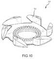
- FIGS. 10 and 11illustrate a second stage TPX wheel for holding the axle flow ring.
- FIG. 12illustrates a schematic view of a coolant chamber disposed in a portion of the pre-combustion fuel mixing device.
- FIG. 13illustrates a schematic view of a first stage and a second stage of the pre-combustion fuel mixing device shown in FIGS. 1 , 2 , 7 , and 8 ;
- pre-combustion chamberrefers to an area that is not a combustion area.
- the mixing apparatusmay comprise, for example, a pre-combustion fuel mixing device 100 ( FIGS. 1-3 ).
- the pre-combustion fuel mixing device 100may provide a premixed supply of fuel and oxidant to an internal combustion engine or other device.
- FIGS. 1 and 2illustrate the pre-combustion fuel mixing device 100 fully assembled and
- FIG. 3illustrates the pre-combustion fuel mixing device in cross-section.
- the pre-combustion fuel mixing device 100may include a housing 102 .
- the housing 102is a generally rigid structure that may be made of metal, ceramic, composite, plastic, or other materials.
- the housing 102may encloses a number of internal components which are described below.
- the housing 102may comprise any size or shape, although as shown in FIG. 2 , some embodiments of the housing include an oxidant inlet section 104 and a vortex section 106 .
- the oxidant inlet section 104may comprise a throttle body.
- fuel nozzle 400includes a first end 402 and a second end 404 in opposition to one another. A line between the first end 402 and the second end 404 form an axis 406 . At least one port 408 for receiving fuel therethrough is formed on the first end 402 .
- a sidewall 410extends between the first end 402 and the second end 404 of fuel nozzle 400 .
- a plurality of ports 412are provided for introducing the fuel into a pre-combustion chamber 700 ( FIG. 7 ).
- Plurality of ports 412may be arranged in a plurality of rows 414 substantially parallel to one another and substantially perpendicular to the axis 406 between the first end 402 and the second end 406 .
- a plurality of conduits 416may be formed between the one or more ports 408 through the first end 402 and the plurality of ports 412 through the sidewall 410 .
- sidewall 410may include a notch 418 adjacent the first end 402 .
- Notch 418may be configured to allow airflow 420 from the second end 404 to the first end 402 of fuel nozzle 400 . This allows oxidant, such as air, to get from the front of fuel nozzle 400 , e.g., adjacent second side 404 , to the back of fuel nozzle 400 , e.g., adjacent first side 402 , so as to aid in fuel mixing.
- the plurality of rows 414may form a number of bands 422 in parallel to one another. As shown, three bands 422 are provided with decreasing outer diameters. A number of ports 412 may be provided in each of the rows 414 of the parallel bands 422 . For example, four ports 412 extending through the sidewall 410 . Parallel bands 422 may be configured such that fuel shoots down to a corner area and mixes into and with the flow of oxidant.
- Each of the rows 414may include a groove 424 extending through each of the ports 412 extending through the sidewall 410 within each of the parallel bands 422 .
- Groove 424may be configured to provide a more desired mixture of the fuel with the oxidant.
- the sidewall 410is substantially arcuate within a plane 426 formed substantially perpendicular to axis 406 .
- the sidewall 410may include discontinuities, such as one or more notches, or may include portions forming other shapes.
- the second end 404 of fuel nozzlemay form a port 428 for introducing fuel into a pre-combustion chamber 700 ( FIG. 7 ).
- the plurality of ports 412 through the sidewall 410may be disposed on fuel nozzle 400 so as to allow disposal of the second end 404 further into the pre-combustion chamber 700 ( FIG. 7 ) than a fuel injector having a single row of ports through a sidewall.
- fuel nozzle 400may be formed with two ports 430 at the first end 402 .
- Each port 408 of the two ports 430may be configured to receive a separate supply of fuel.
- the fuelingmay include creating a gaseous, homogenous premixture of fuel and oxidizer in a first pre-combustion vortex chamber. Within the first pre-combustion vortex chamber, this may include creating an oxidizer vortex in the first pre-combustion vortex chamber.
- the first pre-combustion vortex chambermay also include introducing fuel at an axis of the oxidizer vortex both axially and radially through an injector having a plurality of ports through a sidewall arranged in a plurality of rows substantially parallel to one another.
- Creating the gaseous, homogeneous premixturemay also include pulverizing the fuel and mixing the fuel with the oxidizer at an axis area of the first pre-combustion vortex chamber. Subsequently, the fueling may include drawing the gaseous, homogenous premixture of fuel and oxidizer from the first pre-combustion vortex chamber into a combustion chamber.
- the housing 102encloses first pre-combustion vortex chamber or first stage 700 having a first compartment 702 , a second compartment 704 , and a third compartment 706 .
- a plurality of angled passages 708 , 710 , 712lead into the first pre-combustion vortex chamber 700 .
- Passage 110facilitates the creation of a vortex or tornado in the first pre-combustion vortex chamber 700 .
- a first oxidant flow introduction path 110 disposed in the housing 102is in fluid communication with the first pre-combustion vortex chamber 700 .
- the first oxidant flow path 110provides a primary air or oxidant source to the first pre-combustion vortex chamber 700 .
- a valve 118 ( FIG. 3 ) disposed in the first oxidant flow path 110may comprise an electronically controlled valve to regulate the flow or flow rate of air into the first pre-combustion vortex chamber 700 . This rate may be based on need.
- an adjustment screw 120may be provided for regulating first valve 118 .
- a second pre-combustion vortex chamber 714is enclosed by the housing 102 .
- the second pre-combustion vortex chamber 714is larger than the first pre-combustion vortex chamber 700 .
- a plurality of angled passages 716 , 718lead into the second pre-combustion vortex chamber 714 for creating a vortex.
- a second oxidant fluid flow path 112may be provided in fluid communication with the second pre-combustion vortex chamber 714 .
- a valve systemmay be provided in flow path 112 .
- a butterfly valve 113 Amay disposed in the second oxidant fluid flow path 112 .
- a stepper motor 113 Bmay actuate butterfly valve 113 A.
- valve systemoperates and opens a predetermined amount based on oxidant need.
- fuel injector 400may be aligned substantially axially with the first and second pre-combustion vortex chambers 700 , 714 .
- Fuel injector 400may include an axial flow channel 416 A/ 428 , in addition to radial flow channels 412 / 416 B.
- Fuel injector 400may be disposed in a cylindrical cavity 720 of the housing 102 and in fluid communication with the first and second pre-combustion vortex chambers 700 , 714 .
- a liquid flow channel 416may be provided in fuel injector 400 .
- an atmospheric vent 430may be provided in fluid communication with liquid flow channel 416 .
- the first compartment 702 of first pre-combustion vortex chamber 700has a first width 702 A.
- the second compartment 704has a second width 704 A.
- the third compartment 706has a third width 706 A.
- the first width 702 Ais substantially similar to the third width 706 A, while the second width 704 A is larger than the first width 702 A.
- the various compartmentsmay be configured with other size relationships to one another.
- FIG. 9illustrates an axle flow ring 723 .
- FIGS. 10 and 11show a wheel 725 (with sides 727 , 728 , respectively) for holding ring 723 .
- an opening 722may be configured to provide a concentric feed of airflow evenly and concentrically through, and to an exit in a direction 724 , out of second pre-combustion chamber 714 .
- opening 722may include a radiused edge with a flange so as to force airflow evenly and concentrically.
- a wall 732 of the third compartment 706may taper outwardly in a direction 734 away from the second compartment 704 .
- the wall 732tapers at an angle 736 of about 120 degrees.
- the fuelingmay include creating a gaseous, homogenous premixture of fuel and oxidizer in a first pre-combustion vortex chamber having a first compartment, a second compartment, and a third compartment.
- the fuelingmay also include drawing the gaseous, homogenous premixture of fuel and oxidizer from the first pre-combustion vortex chamber into a combustion chamber.
- One method of creating a gaseous, homogenous premixture of fuel and oxidizermay include creating an oxidizer vortex in the first compartment and the second compartment of the first pre-combustion vortex chamber. This method may further include introducing fuel into the second compartment along an axis of the oxidizer vortex and into the first compartment in directions perpendicular to the axis. Creating the gaseous, homogenous premixture may also include pulverizing the fuel and mixing the fuel with the oxidizer at radial areas in the first compartment and in the second compartment, and axial areas in the second compartment and third compartment of the first pre-combustion vortex chamber.
- creating a gaseous, homogenous premixture of fuel and oxidizermay include creating an oxidizer vortex in the first compartment and the second compartment of the first pre-combustion vortex chamber. This method may include introducing fuel into the second compartment along an axis of the oxidizer vortex and into the first compartment along directions perpendicular to the axis. Creating a gaseous, homogenous premixture of fuel and oxidizer may also include pulverizing the fuel and mixing the fuel with the oxidizer at radial areas in the first compartment and in the second compartment, and axial areas in the second compartment and the third compartment of the first pre-combustion vortex chamber.
- Creating an oxidizer vortexmay include introducing the oxidizer into the first pre-combustion vortex chamber at a non-tangential, non-radial angle through multiple fluid passageways.
- the passagewaysmay define a plurality of ports arranged in a plurality of rows substantially parallel to one another and substantially perpendicular to the axis of the oxidizer vortex.
- creating a gaseous, homogenous premixture of fuel and oxidizermay include providing a primary stage oxidizer introduction path.
- the methodmay also include providing a secondary stage oxidizer introduction path.
- Creating a gaseous, homogenous premixture of fuel and oxidizermay include opening a valve in the secondary stage oxidizer introduction path upon reaching a predetermined oxidizer requirement threshold. This may be followed by creating an oxidizer vortex in a second pre-combustion vortex chamber with fluid flow from the secondary stage oxidizer introduction path.
- the methodmay include introducing fuel at an axis of the oxidizer vortex.
- the methodmay also include pulverizing the fuel and mixing the fuel with the oxidizer.
- Creating a gaseous, homogenous premixture of fuel and oxidizermay include providing a primary stage oxidizer introduction path, and providing a secondary stage oxidizer introduction path.
- the methodmay include opening a valve in the secondary stage oxidizer introduction path upon reaching a predetermined oxidizer requirement threshold and holding open a valve in the primary stage oxidizer introduction path. This may be followed by creating an oxidizer vortex in a second pre-combustion vortex chamber with fluid flow from the secondary stage oxidizer introduction path.
- the methodmay include introducing fuel at an axis of the oxidizer vortex.
- the methodmay also include pulverizing the fuel and mixing the fuel with the oxidizer.
- the methodmay include creating an oxidizer vortex in the first pre-combustion vortex chamber.
- Creating a gaseous, homogenous premixture of fuel and oxidizermay include introducing fuel at an axis of the oxidizer vortex both axially into the second compartment and radially into the first compartment through an injector.
- the methodmay include pulverizing the fuel and mixing the fuel with the oxidizer at radial areas in the first compartment and the second compartment, and axial areas in the second compartment and the third compartment of the first pre-combustion vortex chamber.
- creating a gaseous, homogenous premixture of fuel and oxidizermay include providing a primary stage oxidizer introduction path, and providing a secondary stage oxidizer introduction path.
- the methodmay also include mechanically opening a throttle valve in the second stage oxidizer introduction path according to fuel pedal position.
- the methodmay further include creating an oxidizer vortex in a second pre-combustion vortex chamber with fluid flow from the secondary stage oxidizer introduction path. This may be followed by introducing fuel at an axis of the oxidizer vortex.
- the methodmay include pulverizing the fuel and mixing the fuel with the oxidizer.
- the methodmay further include warming airflow through the primary stage oxidizer introduction path with coolant disposed in a coolant chamber.
- the primary stage oxidizer introduction path and the coolant chambersharing a common wall having an arcuate shape.
- the methodmay include cycling the coolant from an engine cooling system through an inlet of the coolant chamber. Simultaneously, the method may also include returning the coolant to the engine cooling system through an outlet of the cooling chamber.
- the first stage 700may include a high vacuum, low flow rate vortex chamber.
- the second stage 714may include a larger volume than the first stage and comprises a low vacuum, high flow rate vortex chamber.
- the first oxidation source 110is open to the first stage 700 until a predetermined flow rate is reached. Subsequently, the second oxidation source 112 is opened when the predetermined flow rate is reached.
- a water jacket 738disposed about the first stage 700 of the two stage vortex chamber 700 , 714 .
- Water jacket 738which may be referred to as a coolant chamber 738 , may be configured for warming airflow through the primary stage oxidizer introduction path 110 .
- a common wall 740 of the coolant chamber 738 and the primary stage oxidizer introduction path 110may be provided in an arcuate shape.
- An inlet 114may be provided for receiving the coolant from an engine cooling system into the coolant chamber 738 . Similar to the inlet 114 , an outlet 116 may be provided for returning the coolant to the engine cooling system from the coolant chamber 738 .
- the coolant of water jacket 738primarily cools the engine and operates in steady state conditions at approximately 87-100° C. (190-212° F.).
Landscapes
- Engineering & Computer Science (AREA)
- Chemical & Material Sciences (AREA)
- Combustion & Propulsion (AREA)
- Mechanical Engineering (AREA)
- General Engineering & Computer Science (AREA)
- Combustion Methods Of Internal-Combustion Engines (AREA)
Abstract
Description
Claims (16)
Priority Applications (2)
| Application Number | Priority Date | Filing Date | Title |
|---|---|---|---|
| US11/835,246US8028674B2 (en) | 2007-08-07 | 2007-08-07 | Fuel processor apparatus and method |
| PCT/US2008/066752WO2009020703A1 (en) | 2007-08-07 | 2008-06-12 | Fuel processor apparatus and method |
Applications Claiming Priority (1)
| Application Number | Priority Date | Filing Date | Title |
|---|---|---|---|
| US11/835,246US8028674B2 (en) | 2007-08-07 | 2007-08-07 | Fuel processor apparatus and method |
Publications (2)
| Publication Number | Publication Date |
|---|---|
| US20090038582A1 US20090038582A1 (en) | 2009-02-12 |
| US8028674B2true US8028674B2 (en) | 2011-10-04 |
Family
ID=40341623
Family Applications (1)
| Application Number | Title | Priority Date | Filing Date |
|---|---|---|---|
| US11/835,246Active2030-08-03US8028674B2 (en) | 2007-08-07 | 2007-08-07 | Fuel processor apparatus and method |
Country Status (2)
| Country | Link |
|---|---|
| US (1) | US8028674B2 (en) |
| WO (1) | WO2009020703A1 (en) |
Cited By (2)
| Publication number | Priority date | Publication date | Assignee | Title |
|---|---|---|---|---|
| EP3012431A1 (en) | 2014-10-21 | 2016-04-27 | Caterpillar Energy Solutions GmbH | Pre-combustion chamber assembly for internal combustion engines |
| EP3118433A1 (en) | 2015-07-16 | 2017-01-18 | Caterpillar Energy Solutions GmbH | Pre-combustion chamber assembly for internal combustion engines |
Families Citing this family (1)
| Publication number | Priority date | Publication date | Assignee | Title |
|---|---|---|---|---|
| WO2024206661A2 (en)* | 2023-03-28 | 2024-10-03 | Regents Of The University Of Minnesota | Ammonia pre-chamber internal combustion engine |
Citations (94)
| Publication number | Priority date | Publication date | Assignee | Title |
|---|---|---|---|---|
| US634242A (en) | 1898-07-02 | 1899-10-03 | John W Lambert | Mixing device for gasolene-engines. |
| US751292A (en) | 1904-02-02 | Mixer for gasolene-engines | ||
| US860259A (en) | 1906-08-31 | 1907-07-16 | Reuben Smith | Fuel-oil burner. |
| US1163437A (en) | 1912-01-23 | 1915-12-07 | Donald Barns Morison | Apparatus for cleansing steam and heating water. |
| US1233557A (en) | 1916-05-27 | 1917-07-17 | Frank P Schemmel | Carbureter. |
| US1309719A (en) | 1919-07-15 | bt hdv | ||
| US1313521A (en) | 1919-08-19 | Carbureter | ||
| US1451063A (en) | 1923-04-10 | Burner | ||
| US1471220A (en) | 1919-10-06 | 1923-10-16 | Roy M Tangye | Carburetor |
| US1626085A (en) | 1923-03-19 | 1927-04-26 | Henriot Louis | Carburetor |
| FR746984A (en) | 1932-12-06 | 1933-06-09 | Fuel mixing device, in particular for internal combustion engines | |
| US2071717A (en) | 1933-12-23 | 1937-02-23 | John R Winkle | Fuel and air mixing device |
| US2242274A (en)* | 1937-09-01 | 1941-05-20 | Thysse John | Combustion chamber for internal combustion engines |
| US2413420A (en) | 1940-02-26 | 1946-12-31 | Thermo Plastics Corp | Method and apparatus for dispersing or drying fluent material in high velocity elastic fluid jets |
| US2599422A (en) | 1948-05-27 | 1952-06-03 | Loyde E Yettaw | Atomizer |
| FR1156341A (en) | 1956-07-02 | 1958-05-14 | Pillard Chauffage | Mechanical atomizing liquid fuel burner with very large flow rate variation and little variation in divergence |
| DE1108666B (en) | 1956-01-21 | 1961-06-15 | Krauss Maffei Ag | Device for mixing a flowing working substance with at least one flowing medium made of gas or a liquid |
| US3279179A (en)* | 1964-05-12 | 1966-10-18 | Kemenczky Establishment | Jet propulsion engine with fuel injection means |
| US3286997A (en) | 1961-04-18 | 1966-11-22 | Thiokol Chemical Corp | Vortex fuel injector |
| US3336017A (en) | 1965-01-12 | 1967-08-15 | Univ California | Compound cyclonic flow inductor and improved carburetor embodying same |
| US3395899A (en) | 1965-09-28 | 1968-08-06 | Univ California | Carburetor |
| US3414242A (en) | 1965-12-30 | 1968-12-03 | Bouteleux Rene | Device for balanced homogenization of air and liquid fuel mixtures in internal combustion engines |
| US3506589A (en) | 1967-12-22 | 1970-04-14 | Norgren Co C A | Aerosol generator |
| US3512359A (en) | 1968-05-24 | 1970-05-19 | Gen Electric | Dummy swirl cup combustion chamber |
| US3515676A (en) | 1967-09-18 | 1970-06-02 | Eaton Yale & Towne | Oil fog generating device |
| US3651619A (en) | 1970-03-30 | 1972-03-28 | Mitsugi Miura | Apparatus for purification of gas |
| US3667221A (en) | 1969-04-17 | 1972-06-06 | Gen Electric | Fuel delivery apparatus |
| US3733060A (en) | 1972-04-10 | 1973-05-15 | M Merritt | Mist generator |
| US3761065A (en) | 1971-05-21 | 1973-09-25 | Rp Ind Inc | High efficiency direct gas-liquid contact apparatus and methods |
| US3778038A (en) | 1970-03-06 | 1973-12-11 | Dresser Ind | Method and apparatus for mixing and modulating liquid fuel and intake air for an internal combustion engine |
| US3811278A (en) | 1973-02-01 | 1974-05-21 | Gen Electric | Fuel injection apparatus |
| US3866585A (en) | 1970-10-19 | 1975-02-18 | Richard D Kopa | High energy fuel atomization and a dual carburetion embodying same |
| US3944634A (en) | 1973-05-29 | 1976-03-16 | John M. Anderson | Carburetor idling system |
| US3946552A (en) | 1973-09-10 | 1976-03-30 | General Electric Company | Fuel injection apparatus |
| US3972182A (en) | 1973-09-10 | 1976-08-03 | General Electric Company | Fuel injection apparatus |
| US4030283A (en) | 1974-03-25 | 1977-06-21 | Societe Suisse Pour L'industrie Horlogere Management Services S.A. | Electrically driven time piece with means for effecting a precise setting of time |
| US4062663A (en) | 1976-02-04 | 1977-12-13 | Deuterium Corporation | Contact apparatus for multiphase processing |
| US4087862A (en) | 1975-12-11 | 1978-05-02 | Exxon Research & Engineering Co. | Bladeless mixer and system |
| US4159881A (en) | 1976-09-02 | 1979-07-03 | Achille Gogneau | Turbulent flow conveying device for a mixture |
| US4173863A (en) | 1975-12-25 | 1979-11-13 | Citizen Watch Company Limited | Analog quartz timepiece |
| US4178134A (en) | 1978-01-06 | 1979-12-11 | Wynn Oil Company | Engine coolant system flush attachment for coolant hose |
| US4182280A (en)* | 1977-06-02 | 1980-01-08 | Shekleton Jack R | Vortex automotive combustion engine |
| US4185453A (en) | 1976-10-25 | 1980-01-29 | Societe Suisse Pour L'industrie Horlogere Management Services S.A. | Time setting and correcting circuit for electronic timepieces |
| US4215535A (en) | 1978-01-19 | 1980-08-05 | United Technologies Corporation | Method and apparatus for reducing nitrous oxide emissions from combustors |
| US4217313A (en) | 1978-04-21 | 1980-08-12 | Dmitrievsky Anatoly V | Device for reducing noxious emissions from carburetor internal combustion engines |
| US4232384A (en) | 1976-02-23 | 1980-11-04 | Societe Suisse Pour L'industrie Horlogere Management Services S.A. | Timesetting arrangement for electrical timepieces |
| US4245338A (en) | 1977-11-10 | 1981-01-13 | Citizen Watch Company Limited | Time correction system for an electronic timepiece |
| US4255410A (en) | 1976-02-04 | 1981-03-10 | Deuterium Corporation | Contact method for multiphase processing |
| US4261048A (en) | 1975-12-25 | 1981-04-07 | Citizen Watch Company Limited | Analog quartz timepiece |
| US4261354A (en) | 1979-11-26 | 1981-04-14 | Nelson Byron G | Inhalator-breathing apparatus |
| US4267131A (en) | 1977-01-25 | 1981-05-12 | Rhone-Poulenc Industries | Method for intimate contacting of plural phases and phase contactor apparatus therefor |
| US4275463A (en) | 1978-07-19 | 1981-06-23 | Kabushiki Kaisha Daini Seikosha | Electronic timepiece |
| US4308607A (en) | 1978-04-22 | 1981-12-29 | Citizen Watch Company Limited | Electronic timepiece |
| US4320092A (en) | 1979-08-24 | 1982-03-16 | Mitsubishi Jukogyo Kabushiki Kaisha | Reaction vessel |
| JPS5792622A (en) | 1980-11-29 | 1982-06-09 | Nippon Furnace Kogyo Kaisha Ltd | Combustion cylinder of heavy load burner |
| US4335804A (en) | 1979-07-30 | 1982-06-22 | Bardin Viktor P | Vortex-type oil mist generator |
| US4358289A (en)* | 1978-04-26 | 1982-11-09 | Phillips Petroleum Company | Method and apparatus for producing carbon black |
| US4421079A (en)* | 1982-09-30 | 1983-12-20 | Ford Motor Company | Diesel engine combination fuel vaporizer and air/fuel mixer |
| US4452239A (en) | 1980-03-25 | 1984-06-05 | Hilal Malem | Medical nebulizing apparatus |
| US4464314A (en) | 1980-01-02 | 1984-08-07 | Surovikin Vitaly F | Aerodynamic apparatus for mixing components of a fuel mixture |
| US4515734A (en) | 1983-01-28 | 1985-05-07 | Rock Howard P | Fuel efficient, low pollution carburetor and methods |
| WO1985003741A1 (en) | 1984-02-14 | 1985-08-29 | Trenner, Otto, Sen. | Additional air supply device for carburators of internal combustion engines |
| US4568500A (en) | 1983-01-28 | 1986-02-04 | Rock Howard P | Fuel efficient, low pollution carburetor |
| DE3511094A1 (en) | 1985-03-27 | 1986-10-09 | Doduco KG Dr. Eugen Dürrwächter, 7530 Pforzheim | Device for feeding an auxiliary gas flow into the intake port of a spark ignition engine |
| SU1275187A1 (en)* | 1985-07-30 | 1986-12-07 | Ордена Ленина Производственное Объединение "Красный Котельщик" Им.60-Летия Ссср | Combustion apparatus |
| US4635857A (en) | 1980-12-08 | 1987-01-13 | Vortran Corporation | Atomizing apparatus |
| SU1357032A1 (en) | 1986-03-31 | 1987-12-07 | Казанский Химико-Технологический Институт Им.С.М.Кирова | Heat-mass exchange apparatus |
| US4726686A (en) | 1985-07-30 | 1988-02-23 | Hartmut Wolf | Swirl chamber |
| US4842777A (en) | 1987-08-07 | 1989-06-27 | E & M Lamort | Pressurized mixing injector |
| US4943704A (en) | 1989-02-06 | 1990-07-24 | Ryder International Corporation | Humidifier apparatus |
| US4992206A (en) | 1988-11-01 | 1991-02-12 | Lowndes Engineering Co., Inc. | Aerosol generator apparatus and method of use |
| US5008048A (en) | 1988-12-05 | 1991-04-16 | Ryder Steven L | Position insensitive aspirator |
| US5071068A (en) | 1987-02-28 | 1991-12-10 | Hirt Combustion Engineers Ltd. | Atomizer |
| US5169302A (en) | 1989-12-22 | 1992-12-08 | Asea Brown Boveri Ltd. | Burner |
| DE9402811U1 (en) | 1993-12-03 | 1994-07-07 | Rubenberger, Karl, 85435 Erding | Vortex chamber atomizer |
| US5340306A (en) | 1991-12-23 | 1994-08-23 | Asea Brown Boveri Ltd. | Device for mixing two gaseous components and burner in which this device is employed |
| US5472645A (en) | 1994-11-23 | 1995-12-05 | Cyclone Technologies, Inc. | Cyclone vortex system and process |
| US5476093A (en) | 1992-02-14 | 1995-12-19 | Huhtamaki Oy | Device for more effective pulverization of a powdered inhalation medicament |
| US5487378A (en) | 1990-12-17 | 1996-01-30 | Minnesota Mining And Manufacturing Company | Inhaler |
| DE4427466A1 (en) | 1994-08-03 | 1996-02-15 | Kurt Burkhardt | IC engine for piston engines in automotive industry |
| GB2296037A (en) | 1994-12-15 | 1996-06-19 | Ford Motor Co | Spark ignition engine charge intake system |
| US5529059A (en) | 1991-08-01 | 1996-06-25 | Sepracor Inc. | Inhalation devices |
| US5672187A (en) | 1994-11-23 | 1997-09-30 | Cyclone Technologies Inc. | Cyclone vortex system and process |
| US5687710A (en) | 1992-12-18 | 1997-11-18 | Schering Corporation | Inhaler for powdered medications having spiral deagglomeration chamber |
| US5775320A (en) | 1991-07-02 | 1998-07-07 | Inhale Therapeutic Systems | Method and device for delivering aerosolized medicaments |
| US5848750A (en) | 1996-08-21 | 1998-12-15 | Envirocare International, Inc. | Atomizing nozzle |
| US6113078A (en) | 1998-03-18 | 2000-09-05 | Lytesyde, Llc | Fluid processing method |
| US6151899A (en) | 1998-05-09 | 2000-11-28 | Alstom Gas Turbines Limited | Gas-turbine engine combustor |
| US6536748B1 (en) | 1999-11-05 | 2003-03-25 | Honda Giken Kogyo Kabushiki Kaisha | Evaporator raw fuel injection apparatus |
| US20030155666A1 (en) | 2002-01-15 | 2003-08-21 | Kiyoshi Amou | Fuel vaporization promoting apparatus and fuel carburetion accelerator |
| US20040021235A1 (en) | 2002-05-31 | 2004-02-05 | Catalytica Energy Systems, Inc. | Fuel-air premixing system for a catalytic combustor |
| US20040061001A1 (en) | 2002-09-30 | 2004-04-01 | Chien-Pei Mao | Discrete jet atomizer |
| US20050035219A1 (en) | 2003-08-15 | 2005-02-17 | Rock Kelly P. | Fuel processor apparatus and method |
| US20070169760A1 (en) | 2006-01-23 | 2007-07-26 | Rock Kelly P | Fuel processor apparatus and method |
Family Cites Families (3)
| Publication number | Priority date | Publication date | Assignee | Title |
|---|---|---|---|---|
| DE1193113B (en)* | 1964-04-14 | 1965-05-20 | Telefunken Patent | Circuit arrangement for flattening traffic peaks that occur in telecommunications, in particular telephone branch exchanges |
| US3561619A (en)* | 1968-01-15 | 1971-02-09 | Fmc Corp | Warehousing system and apparatus therefor |
| JP3631925B2 (en)* | 1999-09-07 | 2005-03-23 | 矢崎総業株式会社 | Current detector and electrical junction box using the same |
- 2007
- 2007-08-07USUS11/835,246patent/US8028674B2/enactiveActive
- 2008
- 2008-06-12WOPCT/US2008/066752patent/WO2009020703A1/enactiveApplication Filing
Patent Citations (98)
| Publication number | Priority date | Publication date | Assignee | Title |
|---|---|---|---|---|
| US751292A (en) | 1904-02-02 | Mixer for gasolene-engines | ||
| US1309719A (en) | 1919-07-15 | bt hdv | ||
| US1313521A (en) | 1919-08-19 | Carbureter | ||
| US1451063A (en) | 1923-04-10 | Burner | ||
| US634242A (en) | 1898-07-02 | 1899-10-03 | John W Lambert | Mixing device for gasolene-engines. |
| US860259A (en) | 1906-08-31 | 1907-07-16 | Reuben Smith | Fuel-oil burner. |
| US1163437A (en) | 1912-01-23 | 1915-12-07 | Donald Barns Morison | Apparatus for cleansing steam and heating water. |
| US1233557A (en) | 1916-05-27 | 1917-07-17 | Frank P Schemmel | Carbureter. |
| US1471220A (en) | 1919-10-06 | 1923-10-16 | Roy M Tangye | Carburetor |
| US1626085A (en) | 1923-03-19 | 1927-04-26 | Henriot Louis | Carburetor |
| FR746984A (en) | 1932-12-06 | 1933-06-09 | Fuel mixing device, in particular for internal combustion engines | |
| US2071717A (en) | 1933-12-23 | 1937-02-23 | John R Winkle | Fuel and air mixing device |
| US2242274A (en)* | 1937-09-01 | 1941-05-20 | Thysse John | Combustion chamber for internal combustion engines |
| US2413420A (en) | 1940-02-26 | 1946-12-31 | Thermo Plastics Corp | Method and apparatus for dispersing or drying fluent material in high velocity elastic fluid jets |
| US2599422A (en) | 1948-05-27 | 1952-06-03 | Loyde E Yettaw | Atomizer |
| DE1108666B (en) | 1956-01-21 | 1961-06-15 | Krauss Maffei Ag | Device for mixing a flowing working substance with at least one flowing medium made of gas or a liquid |
| FR1156341A (en) | 1956-07-02 | 1958-05-14 | Pillard Chauffage | Mechanical atomizing liquid fuel burner with very large flow rate variation and little variation in divergence |
| US3286997A (en) | 1961-04-18 | 1966-11-22 | Thiokol Chemical Corp | Vortex fuel injector |
| US3279179A (en)* | 1964-05-12 | 1966-10-18 | Kemenczky Establishment | Jet propulsion engine with fuel injection means |
| US3336017A (en) | 1965-01-12 | 1967-08-15 | Univ California | Compound cyclonic flow inductor and improved carburetor embodying same |
| US3395899A (en) | 1965-09-28 | 1968-08-06 | Univ California | Carburetor |
| US3414242A (en) | 1965-12-30 | 1968-12-03 | Bouteleux Rene | Device for balanced homogenization of air and liquid fuel mixtures in internal combustion engines |
| US3515676A (en) | 1967-09-18 | 1970-06-02 | Eaton Yale & Towne | Oil fog generating device |
| US3506589A (en) | 1967-12-22 | 1970-04-14 | Norgren Co C A | Aerosol generator |
| US3512359A (en) | 1968-05-24 | 1970-05-19 | Gen Electric | Dummy swirl cup combustion chamber |
| US3667221A (en) | 1969-04-17 | 1972-06-06 | Gen Electric | Fuel delivery apparatus |
| US3778038A (en) | 1970-03-06 | 1973-12-11 | Dresser Ind | Method and apparatus for mixing and modulating liquid fuel and intake air for an internal combustion engine |
| US3651619A (en) | 1970-03-30 | 1972-03-28 | Mitsugi Miura | Apparatus for purification of gas |
| US3866585A (en) | 1970-10-19 | 1975-02-18 | Richard D Kopa | High energy fuel atomization and a dual carburetion embodying same |
| US3761065A (en) | 1971-05-21 | 1973-09-25 | Rp Ind Inc | High efficiency direct gas-liquid contact apparatus and methods |
| US3733060A (en) | 1972-04-10 | 1973-05-15 | M Merritt | Mist generator |
| US3811278A (en) | 1973-02-01 | 1974-05-21 | Gen Electric | Fuel injection apparatus |
| US3944634A (en) | 1973-05-29 | 1976-03-16 | John M. Anderson | Carburetor idling system |
| US3946552A (en) | 1973-09-10 | 1976-03-30 | General Electric Company | Fuel injection apparatus |
| US3972182A (en) | 1973-09-10 | 1976-08-03 | General Electric Company | Fuel injection apparatus |
| US4030283A (en) | 1974-03-25 | 1977-06-21 | Societe Suisse Pour L'industrie Horlogere Management Services S.A. | Electrically driven time piece with means for effecting a precise setting of time |
| US4087862A (en) | 1975-12-11 | 1978-05-02 | Exxon Research & Engineering Co. | Bladeless mixer and system |
| US4173863A (en) | 1975-12-25 | 1979-11-13 | Citizen Watch Company Limited | Analog quartz timepiece |
| US4261048A (en) | 1975-12-25 | 1981-04-07 | Citizen Watch Company Limited | Analog quartz timepiece |
| US4255410A (en) | 1976-02-04 | 1981-03-10 | Deuterium Corporation | Contact method for multiphase processing |
| US4062663A (en) | 1976-02-04 | 1977-12-13 | Deuterium Corporation | Contact apparatus for multiphase processing |
| US4232384A (en) | 1976-02-23 | 1980-11-04 | Societe Suisse Pour L'industrie Horlogere Management Services S.A. | Timesetting arrangement for electrical timepieces |
| US4159881A (en) | 1976-09-02 | 1979-07-03 | Achille Gogneau | Turbulent flow conveying device for a mixture |
| US4185453A (en) | 1976-10-25 | 1980-01-29 | Societe Suisse Pour L'industrie Horlogere Management Services S.A. | Time setting and correcting circuit for electronic timepieces |
| US4267131A (en) | 1977-01-25 | 1981-05-12 | Rhone-Poulenc Industries | Method for intimate contacting of plural phases and phase contactor apparatus therefor |
| US4182280A (en)* | 1977-06-02 | 1980-01-08 | Shekleton Jack R | Vortex automotive combustion engine |
| US4245338A (en) | 1977-11-10 | 1981-01-13 | Citizen Watch Company Limited | Time correction system for an electronic timepiece |
| US4178134A (en) | 1978-01-06 | 1979-12-11 | Wynn Oil Company | Engine coolant system flush attachment for coolant hose |
| US4215535A (en) | 1978-01-19 | 1980-08-05 | United Technologies Corporation | Method and apparatus for reducing nitrous oxide emissions from combustors |
| US4217313A (en) | 1978-04-21 | 1980-08-12 | Dmitrievsky Anatoly V | Device for reducing noxious emissions from carburetor internal combustion engines |
| US4308607A (en) | 1978-04-22 | 1981-12-29 | Citizen Watch Company Limited | Electronic timepiece |
| US4358289A (en)* | 1978-04-26 | 1982-11-09 | Phillips Petroleum Company | Method and apparatus for producing carbon black |
| US4275463A (en) | 1978-07-19 | 1981-06-23 | Kabushiki Kaisha Daini Seikosha | Electronic timepiece |
| US4335804A (en) | 1979-07-30 | 1982-06-22 | Bardin Viktor P | Vortex-type oil mist generator |
| US4320092A (en) | 1979-08-24 | 1982-03-16 | Mitsubishi Jukogyo Kabushiki Kaisha | Reaction vessel |
| US4261354A (en) | 1979-11-26 | 1981-04-14 | Nelson Byron G | Inhalator-breathing apparatus |
| US4464314A (en) | 1980-01-02 | 1984-08-07 | Surovikin Vitaly F | Aerodynamic apparatus for mixing components of a fuel mixture |
| US4452239A (en) | 1980-03-25 | 1984-06-05 | Hilal Malem | Medical nebulizing apparatus |
| JPS5792622A (en) | 1980-11-29 | 1982-06-09 | Nippon Furnace Kogyo Kaisha Ltd | Combustion cylinder of heavy load burner |
| US4635857A (en) | 1980-12-08 | 1987-01-13 | Vortran Corporation | Atomizing apparatus |
| US4421079A (en)* | 1982-09-30 | 1983-12-20 | Ford Motor Company | Diesel engine combination fuel vaporizer and air/fuel mixer |
| US4515734A (en) | 1983-01-28 | 1985-05-07 | Rock Howard P | Fuel efficient, low pollution carburetor and methods |
| US4568500A (en) | 1983-01-28 | 1986-02-04 | Rock Howard P | Fuel efficient, low pollution carburetor |
| WO1985003741A1 (en) | 1984-02-14 | 1985-08-29 | Trenner, Otto, Sen. | Additional air supply device for carburators of internal combustion engines |
| DE3511094A1 (en) | 1985-03-27 | 1986-10-09 | Doduco KG Dr. Eugen Dürrwächter, 7530 Pforzheim | Device for feeding an auxiliary gas flow into the intake port of a spark ignition engine |
| SU1275187A1 (en)* | 1985-07-30 | 1986-12-07 | Ордена Ленина Производственное Объединение "Красный Котельщик" Им.60-Летия Ссср | Combustion apparatus |
| US4726686A (en) | 1985-07-30 | 1988-02-23 | Hartmut Wolf | Swirl chamber |
| SU1357032A1 (en) | 1986-03-31 | 1987-12-07 | Казанский Химико-Технологический Институт Им.С.М.Кирова | Heat-mass exchange apparatus |
| US5071068A (en) | 1987-02-28 | 1991-12-10 | Hirt Combustion Engineers Ltd. | Atomizer |
| US4842777A (en) | 1987-08-07 | 1989-06-27 | E & M Lamort | Pressurized mixing injector |
| US4992206A (en) | 1988-11-01 | 1991-02-12 | Lowndes Engineering Co., Inc. | Aerosol generator apparatus and method of use |
| US5008048A (en) | 1988-12-05 | 1991-04-16 | Ryder Steven L | Position insensitive aspirator |
| US4943704A (en) | 1989-02-06 | 1990-07-24 | Ryder International Corporation | Humidifier apparatus |
| US5169302A (en) | 1989-12-22 | 1992-12-08 | Asea Brown Boveri Ltd. | Burner |
| US5487378A (en) | 1990-12-17 | 1996-01-30 | Minnesota Mining And Manufacturing Company | Inhaler |
| US5775320A (en) | 1991-07-02 | 1998-07-07 | Inhale Therapeutic Systems | Method and device for delivering aerosolized medicaments |
| US5529059A (en) | 1991-08-01 | 1996-06-25 | Sepracor Inc. | Inhalation devices |
| US5340306A (en) | 1991-12-23 | 1994-08-23 | Asea Brown Boveri Ltd. | Device for mixing two gaseous components and burner in which this device is employed |
| US5476093A (en) | 1992-02-14 | 1995-12-19 | Huhtamaki Oy | Device for more effective pulverization of a powdered inhalation medicament |
| US5687710A (en) | 1992-12-18 | 1997-11-18 | Schering Corporation | Inhaler for powdered medications having spiral deagglomeration chamber |
| DE9402811U1 (en) | 1993-12-03 | 1994-07-07 | Rubenberger, Karl, 85435 Erding | Vortex chamber atomizer |
| DE4427466A1 (en) | 1994-08-03 | 1996-02-15 | Kurt Burkhardt | IC engine for piston engines in automotive industry |
| US5672187A (en) | 1994-11-23 | 1997-09-30 | Cyclone Technologies Inc. | Cyclone vortex system and process |
| US5472645A (en) | 1994-11-23 | 1995-12-05 | Cyclone Technologies, Inc. | Cyclone vortex system and process |
| US5512216A (en) | 1994-11-23 | 1996-04-30 | Matsushita Electric Industrial Co., Ltd. | Cyclone vortex process |
| GB2296037A (en) | 1994-12-15 | 1996-06-19 | Ford Motor Co | Spark ignition engine charge intake system |
| US5848750A (en) | 1996-08-21 | 1998-12-15 | Envirocare International, Inc. | Atomizing nozzle |
| US6347789B1 (en) | 1998-03-18 | 2002-02-19 | Lytesyde, L.L.C. | Fluid processing system |
| US6113078A (en) | 1998-03-18 | 2000-09-05 | Lytesyde, Llc | Fluid processing method |
| US6234459B1 (en) | 1998-03-18 | 2001-05-22 | Lytesyde, Llc | Medication processing system and method |
| US6244573B1 (en) | 1998-03-18 | 2001-06-12 | Lytesyde, Llc | Fluid processing system |
| US6151899A (en) | 1998-05-09 | 2000-11-28 | Alstom Gas Turbines Limited | Gas-turbine engine combustor |
| US6536748B1 (en) | 1999-11-05 | 2003-03-25 | Honda Giken Kogyo Kabushiki Kaisha | Evaporator raw fuel injection apparatus |
| US20030155666A1 (en) | 2002-01-15 | 2003-08-21 | Kiyoshi Amou | Fuel vaporization promoting apparatus and fuel carburetion accelerator |
| US20040021235A1 (en) | 2002-05-31 | 2004-02-05 | Catalytica Energy Systems, Inc. | Fuel-air premixing system for a catalytic combustor |
| US20040061001A1 (en) | 2002-09-30 | 2004-04-01 | Chien-Pei Mao | Discrete jet atomizer |
| US20050035219A1 (en) | 2003-08-15 | 2005-02-17 | Rock Kelly P. | Fuel processor apparatus and method |
| US20070169760A1 (en) | 2006-01-23 | 2007-07-26 | Rock Kelly P | Fuel processor apparatus and method |
Cited By (2)
| Publication number | Priority date | Publication date | Assignee | Title |
|---|---|---|---|---|
| EP3012431A1 (en) | 2014-10-21 | 2016-04-27 | Caterpillar Energy Solutions GmbH | Pre-combustion chamber assembly for internal combustion engines |
| EP3118433A1 (en) | 2015-07-16 | 2017-01-18 | Caterpillar Energy Solutions GmbH | Pre-combustion chamber assembly for internal combustion engines |
Also Published As
| Publication number | Publication date |
|---|---|
| WO2009020703A1 (en) | 2009-02-12 |
| US20090038582A1 (en) | 2009-02-12 |
Similar Documents
| Publication | Publication Date | Title |
|---|---|---|
| US11674479B2 (en) | Multi-physics fluid atomizer and methods | |
| US7500464B2 (en) | Fuel processor apparatus and method for a diesel engine | |
| US11635051B2 (en) | Co-axial dual fluids metering system and methods | |
| US8028674B2 (en) | Fuel processor apparatus and method | |
| US7717096B2 (en) | Fuel processor apparatus and method | |
| WO2012101944A1 (en) | Intake device of internal combustion engine | |
| KR200169740Y1 (en) | Mixer of lpg fuel system for automobile | |
| US20140299676A1 (en) | Dual solenoid dual angle entry multi-physics fuel atomizer | |
| HK40070861A (en) | Liquid atomizer and methods | |
| HK1176907A (en) | Multi-physics fuel atomizer and methods |
Legal Events
| Date | Code | Title | Description |
|---|---|---|---|
| AS | Assignment | Owner name:LYTESYDE, LLC, NEVADA Free format text:ASSIGNMENT OF ASSIGNORS INTEREST;ASSIGNORS:ROCK, KELLY P.;NADEAU, BRUCE E., JR.;REEL/FRAME:019661/0163 Effective date:20070807 | |
| STCF | Information on status: patent grant | Free format text:PATENTED CASE | |
| AS | Assignment | Owner name:ENGINETICS, LLC, NORTH CAROLINA Free format text:ASSIGNMENT OF ASSIGNORS INTEREST;ASSIGNOR:LYTESYDE, LLC;REEL/FRAME:032042/0891 Effective date:20130329 | |
| FPAY | Fee payment | Year of fee payment:4 | |
| MAFP | Maintenance fee payment | Free format text:PAYMENT OF MAINTENANCE FEE, 8TH YR, SMALL ENTITY (ORIGINAL EVENT CODE: M2552); ENTITY STATUS OF PATENT OWNER: SMALL ENTITY Year of fee payment:8 | |
| MAFP | Maintenance fee payment | Free format text:PAYMENT OF MAINTENANCE FEE, 12TH YR, SMALL ENTITY (ORIGINAL EVENT CODE: M2553); ENTITY STATUS OF PATENT OWNER: SMALL ENTITY Year of fee payment:12 | |
| AS | Assignment | Owner name:V-STAX, LLC, FLORIDA Free format text:ASSIGNMENT OF ASSIGNORS INTEREST;ASSIGNOR:ENGINETICS, LLC;REEL/FRAME:072206/0444 Effective date:20250718 |