US8028646B2 - Coating medical devices - Google Patents
Coating medical devicesDownload PDFInfo
- Publication number
- US8028646B2 US8028646B2US11/390,606US39060606AUS8028646B2US 8028646 B2US8028646 B2US 8028646B2US 39060606 AUS39060606 AUS 39060606AUS 8028646 B2US8028646 B2US 8028646B2
- Authority
- US
- United States
- Prior art keywords
- medical device
- stent structure
- stent
- coating
- dispensing
- Prior art date
- Legal status (The legal status is an assumption and is not a legal conclusion. Google has not performed a legal analysis and makes no representation as to the accuracy of the status listed.)
- Expired - Fee Related, expires
Links
Images


Classifications
- B—PERFORMING OPERATIONS; TRANSPORTING
- B05—SPRAYING OR ATOMISING IN GENERAL; APPLYING FLUENT MATERIALS TO SURFACES, IN GENERAL
- B05B—SPRAYING APPARATUS; ATOMISING APPARATUS; NOZZLES
- B05B5/00—Electrostatic spraying apparatus; Spraying apparatus with means for charging the spray electrically; Apparatus for spraying liquids or other fluent materials by other electric means
- B05B5/025—Discharge apparatus, e.g. electrostatic spray guns
- B05B5/0255—Discharge apparatus, e.g. electrostatic spray guns spraying and depositing by electrostatic forces only
- A—HUMAN NECESSITIES
- A61—MEDICAL OR VETERINARY SCIENCE; HYGIENE
- A61L—METHODS OR APPARATUS FOR STERILISING MATERIALS OR OBJECTS IN GENERAL; DISINFECTION, STERILISATION OR DEODORISATION OF AIR; CHEMICAL ASPECTS OF BANDAGES, DRESSINGS, ABSORBENT PADS OR SURGICAL ARTICLES; MATERIALS FOR BANDAGES, DRESSINGS, ABSORBENT PADS OR SURGICAL ARTICLES
- A61L31/00—Materials for other surgical articles, e.g. stents, stent-grafts, shunts, surgical drapes, guide wires, materials for adhesion prevention, occluding devices, surgical gloves, tissue fixation devices
- A61L31/08—Materials for coatings
- A61L31/10—Macromolecular materials
- A—HUMAN NECESSITIES
- A61—MEDICAL OR VETERINARY SCIENCE; HYGIENE
- A61L—METHODS OR APPARATUS FOR STERILISING MATERIALS OR OBJECTS IN GENERAL; DISINFECTION, STERILISATION OR DEODORISATION OF AIR; CHEMICAL ASPECTS OF BANDAGES, DRESSINGS, ABSORBENT PADS OR SURGICAL ARTICLES; MATERIALS FOR BANDAGES, DRESSINGS, ABSORBENT PADS OR SURGICAL ARTICLES
- A61L31/00—Materials for other surgical articles, e.g. stents, stent-grafts, shunts, surgical drapes, guide wires, materials for adhesion prevention, occluding devices, surgical gloves, tissue fixation devices
- A61L31/14—Materials characterised by their function or physical properties, e.g. injectable or lubricating compositions, shape-memory materials, surface modified materials
- A61L31/16—Biologically active materials, e.g. therapeutic substances
- B—PERFORMING OPERATIONS; TRANSPORTING
- B05—SPRAYING OR ATOMISING IN GENERAL; APPLYING FLUENT MATERIALS TO SURFACES, IN GENERAL
- B05B—SPRAYING APPARATUS; ATOMISING APPARATUS; NOZZLES
- B05B13/00—Machines or plants for applying liquids or other fluent materials to surfaces of objects or other work by spraying, not covered by groups B05B1/00 - B05B11/00
- B05B13/02—Means for supporting work; Arrangement or mounting of spray heads; Adaptation or arrangement of means for feeding work
- B05B13/0221—Means for supporting work; Arrangement or mounting of spray heads; Adaptation or arrangement of means for feeding work characterised by the means for moving or conveying the objects or other work, e.g. conveyor belts
- B05B13/0228—Means for supporting work; Arrangement or mounting of spray heads; Adaptation or arrangement of means for feeding work characterised by the means for moving or conveying the objects or other work, e.g. conveyor belts the movement of the objects being rotative
- B—PERFORMING OPERATIONS; TRANSPORTING
- B05—SPRAYING OR ATOMISING IN GENERAL; APPLYING FLUENT MATERIALS TO SURFACES, IN GENERAL
- B05B—SPRAYING APPARATUS; ATOMISING APPARATUS; NOZZLES
- B05B5/00—Electrostatic spraying apparatus; Spraying apparatus with means for charging the spray electrically; Apparatus for spraying liquids or other fluent materials by other electric means
- B05B5/025—Discharge apparatus, e.g. electrostatic spray guns
- B05B5/03—Discharge apparatus, e.g. electrostatic spray guns characterised by the use of gas, e.g. electrostatically assisted pneumatic spraying
- B—PERFORMING OPERATIONS; TRANSPORTING
- B05—SPRAYING OR ATOMISING IN GENERAL; APPLYING FLUENT MATERIALS TO SURFACES, IN GENERAL
- B05B—SPRAYING APPARATUS; ATOMISING APPARATUS; NOZZLES
- B05B5/00—Electrostatic spraying apparatus; Spraying apparatus with means for charging the spray electrically; Apparatus for spraying liquids or other fluent materials by other electric means
- B05B5/08—Plant for applying liquids or other fluent materials to objects
- B05B5/082—Plant for applying liquids or other fluent materials to objects characterised by means for supporting, holding or conveying the objects
- B—PERFORMING OPERATIONS; TRANSPORTING
- B05—SPRAYING OR ATOMISING IN GENERAL; APPLYING FLUENT MATERIALS TO SURFACES, IN GENERAL
- B05B—SPRAYING APPARATUS; ATOMISING APPARATUS; NOZZLES
- B05B7/00—Spraying apparatus for discharge of liquids or other fluent materials from two or more sources, e.g. of liquid and air, of powder and gas
- B05B7/02—Spray pistols; Apparatus for discharge
- B05B7/06—Spray pistols; Apparatus for discharge with at least one outlet orifice surrounding another approximately in the same plane
- B05B7/062—Spray pistols; Apparatus for discharge with at least one outlet orifice surrounding another approximately in the same plane with only one liquid outlet and at least one gas outlet
- B05B7/066—Spray pistols; Apparatus for discharge with at least one outlet orifice surrounding another approximately in the same plane with only one liquid outlet and at least one gas outlet with an inner liquid outlet surrounded by at least one annular gas outlet
- A—HUMAN NECESSITIES
- A61—MEDICAL OR VETERINARY SCIENCE; HYGIENE
- A61F—FILTERS IMPLANTABLE INTO BLOOD VESSELS; PROSTHESES; DEVICES PROVIDING PATENCY TO, OR PREVENTING COLLAPSING OF, TUBULAR STRUCTURES OF THE BODY, e.g. STENTS; ORTHOPAEDIC, NURSING OR CONTRACEPTIVE DEVICES; FOMENTATION; TREATMENT OR PROTECTION OF EYES OR EARS; BANDAGES, DRESSINGS OR ABSORBENT PADS; FIRST-AID KITS
- A61F2/00—Filters implantable into blood vessels; Prostheses, i.e. artificial substitutes or replacements for parts of the body; Appliances for connecting them with the body; Devices providing patency to, or preventing collapsing of, tubular structures of the body, e.g. stents
- A61F2/82—Devices providing patency to, or preventing collapsing of, tubular structures of the body, e.g. stents
- A61F2/86—Stents in a form characterised by the wire-like elements; Stents in the form characterised by a net-like or mesh-like structure
- A—HUMAN NECESSITIES
- A61—MEDICAL OR VETERINARY SCIENCE; HYGIENE
- A61L—METHODS OR APPARATUS FOR STERILISING MATERIALS OR OBJECTS IN GENERAL; DISINFECTION, STERILISATION OR DEODORISATION OF AIR; CHEMICAL ASPECTS OF BANDAGES, DRESSINGS, ABSORBENT PADS OR SURGICAL ARTICLES; MATERIALS FOR BANDAGES, DRESSINGS, ABSORBENT PADS OR SURGICAL ARTICLES
- A61L2300/00—Biologically active materials used in bandages, wound dressings, absorbent pads or medical devices
- A61L2300/60—Biologically active materials used in bandages, wound dressings, absorbent pads or medical devices characterised by a special physical form
- A61L2300/62—Encapsulated active agents, e.g. emulsified droplets
- A61L2300/622—Microcapsules
- A—HUMAN NECESSITIES
- A61—MEDICAL OR VETERINARY SCIENCE; HYGIENE
- A61L—METHODS OR APPARATUS FOR STERILISING MATERIALS OR OBJECTS IN GENERAL; DISINFECTION, STERILISATION OR DEODORISATION OF AIR; CHEMICAL ASPECTS OF BANDAGES, DRESSINGS, ABSORBENT PADS OR SURGICAL ARTICLES; MATERIALS FOR BANDAGES, DRESSINGS, ABSORBENT PADS OR SURGICAL ARTICLES
- A61L2420/00—Materials or methods for coatings medical devices
- A61L2420/02—Methods for coating medical devices
- B—PERFORMING OPERATIONS; TRANSPORTING
- B05—SPRAYING OR ATOMISING IN GENERAL; APPLYING FLUENT MATERIALS TO SURFACES, IN GENERAL
- B05B—SPRAYING APPARATUS; ATOMISING APPARATUS; NOZZLES
- B05B1/00—Nozzles, spray heads or other outlets, with or without auxiliary devices such as valves, heating means
- B05B1/14—Nozzles, spray heads or other outlets, with or without auxiliary devices such as valves, heating means with multiple outlet openings; with strainers in or outside the outlet opening
- B—PERFORMING OPERATIONS; TRANSPORTING
- B05—SPRAYING OR ATOMISING IN GENERAL; APPLYING FLUENT MATERIALS TO SURFACES, IN GENERAL
- B05B—SPRAYING APPARATUS; ATOMISING APPARATUS; NOZZLES
- B05B5/00—Electrostatic spraying apparatus; Spraying apparatus with means for charging the spray electrically; Apparatus for spraying liquids or other fluent materials by other electric means
- B05B5/025—Discharge apparatus, e.g. electrostatic spray guns
- B05B5/053—Arrangements for supplying power, e.g. charging power
- B05B5/0533—Electrodes specially adapted therefor; Arrangements of electrodes
- B—PERFORMING OPERATIONS; TRANSPORTING
- B05—SPRAYING OR ATOMISING IN GENERAL; APPLYING FLUENT MATERIALS TO SURFACES, IN GENERAL
- B05B—SPRAYING APPARATUS; ATOMISING APPARATUS; NOZZLES
- B05B7/00—Spraying apparatus for discharge of liquids or other fluent materials from two or more sources, e.g. of liquid and air, of powder and gas
- B05B7/02—Spray pistols; Apparatus for discharge
- B05B7/08—Spray pistols; Apparatus for discharge with separate outlet orifices, e.g. to form parallel jets, i.e. the axis of the jets being parallel, to form intersecting jets, i.e. the axis of the jets converging but not necessarily intersecting at a point
- B05B7/0884—Spray pistols; Apparatus for discharge with separate outlet orifices, e.g. to form parallel jets, i.e. the axis of the jets being parallel, to form intersecting jets, i.e. the axis of the jets converging but not necessarily intersecting at a point the outlet orifices for jets constituted by a liquid or a mixture containing a liquid being aligned
- B—PERFORMING OPERATIONS; TRANSPORTING
- B05—SPRAYING OR ATOMISING IN GENERAL; APPLYING FLUENT MATERIALS TO SURFACES, IN GENERAL
- B05D—PROCESSES FOR APPLYING FLUENT MATERIALS TO SURFACES, IN GENERAL
- B05D1/00—Processes for applying liquids or other fluent materials
- B05D1/002—Processes for applying liquids or other fluent materials the substrate being rotated
- B—PERFORMING OPERATIONS; TRANSPORTING
- B05—SPRAYING OR ATOMISING IN GENERAL; APPLYING FLUENT MATERIALS TO SURFACES, IN GENERAL
- B05D—PROCESSES FOR APPLYING FLUENT MATERIALS TO SURFACES, IN GENERAL
- B05D1/00—Processes for applying liquids or other fluent materials
- B05D1/02—Processes for applying liquids or other fluent materials performed by spraying
- B05D1/04—Processes for applying liquids or other fluent materials performed by spraying involving the use of an electrostatic field
- B05D1/045—Processes for applying liquids or other fluent materials performed by spraying involving the use of an electrostatic field on non-conductive substrates
Definitions
- the present inventionrelates to coating medical devices, and more particularly, the present invention relates to coating medical devices using processes such as electrospray, thermophoretic effect, etc.
- medical devicesit is often beneficial to coat medical devices so that the surfaces of such devices have desired properties or provide desired effects.
- Local drug deliverymay be achieved, for example, by coating balloon catheters, stents, and the like with therapeutic agent to be locally delivered.
- the coating of medical devicesmay provide for controlled release, which includes long-term or sustained release, of a bioactive material.
- medical devicesare coated with materials to provide beneficial surface properties.
- medical devicesare often coated with radiopaque materials to allow for fluoroscopic visualization during placement in the body. It is also useful to coat certain devices to achieve enhanced biocompatibility and to improve surface properties such as lubriciousness.
- stentsare implanted within vessels in an effort to maintain the patency thereof by preventing collapse and/or impeding restenosis.
- implantation of a stentmay be accomplished by mounting the stent on the expandable portion of a balloon catheter, maneuvering the catheter through the vasculature so as to position the stent at the treatment site within the body lumen, and inflating the balloon to expand the stent so as to engage the lumen wall.
- the stentdeforms in the expanded configuration allowing the balloon to be deflated and the catheter removed to complete the implantation procedure.
- self-expanding stentsobviates the need for a balloon delivery device. Instead, a constraining sheath that is initially fitted above the stent is simply retracted once the stent is in position adjacent the treatment site.
- Stents and stent delivery cathetersare well known in the art and the various configurations thereof makes it impossible to describe each and every stent structure or related materials.
- the success of a stent placementcan be assessed by evaluating a number of factors, such as thrombosis, neointimal hyperplasia, smooth muscle cell migration, and proliferation following implantation of the stent, injury to the artery wall, overall loss of lumenal patency, stent diameter in vivo, thickness of the stent, and leukocyte adhesion to the lumenal lining of stented arteries.
- factorssuch as thrombosis, neointimal hyperplasia, smooth muscle cell migration, and proliferation following implantation of the stent, injury to the artery wall, overall loss of lumenal patency, stent diameter in vivo, thickness of the stent, and leukocyte adhesion to the lumenal lining of stented arteries.
- the chief areas of concernare early subacute thrombosis and eventual restenosis of the blood vessel due to intimal hyperplasia.
- Therapeutic pharmacological agentshave been developed to address some of the concerns associated with the placement of the stent. It is often desirable to provide localized pharmacological treatment of the vessel at the site being supported by the stent. As it would be convenient to utilize the implanted stent for such purpose, the stent may serve both as a support for a lumenal wall as well as a delivery vehicle for the pharmacological agent.
- coatingshave been applied to medical devices, including stents, by processes such as dipping, spraying, vapor deposition, plasma polymerization, as wells as electroplating and electrostatic deposition. Although many of these processes have been used to produce satisfactory coatings, there are numerous potential drawbacks associated therewith.
- the methods and systems according to the present inventionprovide for the coating of medical devices (e.g., stents, catheters, etc.).
- the present inventionis particularly beneficial for use in coating stent structures.
- a method of coating at least a portion of a medical deviceincludes providing a medical device in a defined volume.
- the medical deviceincludes at least one surface to be coated.
- the methodfurther includes providing a plurality of monodisperse coating particles in the defined volume.
- the plurality of monodisperse coating particleshave a nominal diameter of less than 10 micrometers and a geometrical standard deviation of less than 1.2.
- a plurality of the coating particlesare moved towards the at least one surface of the medical device to form a coating thereon.
- Another method of coating at least a portion of a medical deviceincludes providing a medical device in a defined volume (e.g., the medical device including at least one surface to be coated) and providing one or more nozzle structures, wherein each nozzle structure includes at least one opening terminating at a dispensing end.
- a plurality of coating particlesare provided in the defined volume by dispensing a plurality of microdroplets having an electrical charge associated therewith from the dispensing ends of the one or more nozzle structures using a nonuniform electrical field created between the dispensing ends and the medical device.
- Each of the microdropletsincludes at least a particle and the electrical charge is concentrated on the particle as the microdroplet evaporates.
- the methodfurther includes moving the plurality of coating particles towards the medical device to form a coating on the at least one surface of the medical device using the nonuniform electrical field created between the dispensing ends from which the plurality of coating particles is established and the medical device.
- a method of coating a stent structureincludes providing a stent structure in a defined volume along a stent axis, wherein the stent structure includes at least an interior surface adjacent a defined interior volume and at least an exterior surface. At least a portion of the interior surface of the stent structure adjacent the defined interior volume is coated using at least a plurality of first coating particles (e.g., anti-coagulant particles) and at least a portion of the exterior surface of the stent structure is coated using at least a plurality of second coating particles (e.g., anti-inflammatory particles), wherein the plurality of first coating particles is different than the plurality of second coating particles.
- first coating particlese.g., anti-coagulant particles
- second coating particlese.g., anti-inflammatory particles
- the methods described abovemay also include one or more of the following features: providing an electrical charge on the plurality of monodisperse coating particles; moving a plurality of monodisperse coating particles towards a medical device using an electrical field; providing a plurality of monodisperse coating particles by dispensing a spray of microdroplets having an electrical charge associated therewith, wherein each of the microdroplets includes a particle and wherein the electrical charge is concentrated on the particle as the microdroplet evaporates; an electrical charge of a microdroplet concentrated on the particle that is greater than about 30 percent of the Rayleigh charge limit for the microdroplet; providing a plurality of monodisperse coating particles by dispensing a spray of microdroplets having an electrical charge associated therewith, wherein the electrical charge is concentrated on the particle as the microdroplet evaporates and further wherein, prior to contact with the at least one surface of the medical device, a residual particle volume occupied by the evaporated microdroplet includes less than about 20 percent of a solvent component of the microdroplet; creating an electrical field between an electrode and the
- the methodmay further include one or more of the additional following features: providing a stent structure defined along a stent axis, wherein the stent structure includes at least an interior surface adjacent a defined interior volume and at least an exterior surface that is not adjacent to the defined interior volume; providing one or more nozzle structures, wherein each nozzle structure includes at least one opening terminating at a dispensing end thereof from which a plurality of monodisperse coating particles having an electrical charge applied thereto is dispensed; adjusting the strength of a nonuniform electrical field to prevent particles from reaching an interior surface of a stent structure; dispensing a plurality of monodisperse coating particles from at least one nozzle structure using a nonuniform electrical field created between a dispensing end thereof and a stent structure; moving a plurality of monodisperse coating particles towards at least one surface of a medical device using a thermophoretic effect; positioning a stent structure such that the stent axis coincides with an axis of an
- the methods described hereinmay include one or more of the following features: providing an elongated cylindrical body member defining an interior volume thereof along an axis, positioning the stent structure along the axis of the elongated cylindrical body member, and positioning a plurality of nozzle structures radially about the axis of the elongated cylindrical body member and linearly along the elongated cylindrical body member in the direction of the axis thereof; providing nozzle structures that each include a capillary tube comprised of a body portion and a tapered capillary tip at the dispensing end of the capillary tube; providing nozzles structures that each include a tapered portion used to define an opening, and wherein at least a part of each of the plurality of the nozzle structures extend from an integral conductive portion associated with the body member; providing a plurality of the nozzle structures that each include a solid post along a center axis extending through an opening at the dispensing end; providing one or more nozzle structures that
- a system for use in coating at least one surface of a medical deviceincludes a particle source, a holding fixture operable to position a medical device in a defined volume; and a dispensing device configured to receive source material from the particle source and dispense a plurality of monodisperse coating particles into the defined volume.
- the dispensing deviceincludes one or more nozzle structures, wherein each nozzle structure includes at least one opening terminating at a dispensing end thereof from which a plurality of monodisperse coating particles having an electrical charge applied thereto is dispensed.
- the systemfurther includes an electrode structure that includes an electrode isolated from the dispensing ends of the one or more nozzle structures, wherein the electrode structure is operable to create a nonuniform electrical field between the dispensing ends of the one or more nozzle structures and the medical device for use in providing the plurality of monodisperse coating particles in the defined volume.
- the plurality of monodisperse coating particleshave a nominal diameter of less than 10 micrometers and a geometrical standard deviation of less than 1.2.
- the nonuniform electric fieldis operable to assist in moving a plurality of the coating particles towards the at least one surface of the medical device to form a coating thereon.
- Another system for use in coating at least one surface of a stent structureincludes a particle source and a holding fixture operable to position a stent structure defined along a stent axis in a defined volume, wherein the stent structure includes at least an interior surface adjacent a defined interior volume and at least an exterior surface.
- the systemfurther includes a dispensing device configured to receive source material from the particle source and dispense a plurality of microdroplets having an electrical charge associated therewith from the dispensing ends of the one or more nozzle structures into the defined volume, wherein each of the microdroplets includes at least a particle, and further wherein the electrical charge is concentrated on the particles as the microdroplets evaporate resulting in a plurality of coating particles.
- the systemincludes an electrode structure that includes an electrode isolated from the dispensing ends of the one or more nozzle structures.
- the electrode structureis operable to create a nonuniform electrical field between the dispensing ends of the one or more nozzle structures and the stent structure for use in providing the plurality of coating particles in the defined volume and moving the plurality of coating particles towards the stent structure to form a coating on the at least one surface thereof.
- the systems described hereinmay also include one or more of the following features: an electrode structure that includes a grounded medical device; an electrode structure that includes a ring electrode positioned forward of one or more nozzle structures; a dispensing device configured to dispense a spray of microdroplets having an electrical charge associated therewith, wherein the electrical charge of the microdroplet concentrated upon evaporation on the particle is greater than about 30 percent of the Rayleigh charge limit for the microdroplet; a dispensing device configured such that, prior to contact with the at least one surface of a medical device, a residual particle volume occupied by an evaporated microdroplet includes less than about 20 percent of a solvent component of the originally dispensed microdroplet; a holding fixture operable to position a medical device such that at least one nozzle structure of the dispensing device is operable within the interior volume defined by a medical device structure; an electrode structure operable to create a nonuniform electrical field between the dispensing end of the at least one nozzle structure and a medical device for use in providing the plurality
- the systems described herein for coating a medical devicemay also include a holding fixture that includes an elongated substantially non-conductive tube for receiving the stent structure thereon and an elongated conductive element. At least a portion of the elongated conductive element extends through the elongated substantially non-conductive tube, and further wherein the elongated conductive element comprises a conductive contact section.
- a compression apparatusis configured to provide for expansion of the elongated substantially non-conductive tube such that an exterior surface thereof is in contact with at least a portion of the interior surface of the stent structure and such that a portion of the stent structure is in electrical contact with the conductive contact section.
- the systems described herein for coating a medical devicemay also include one or more of the following features: a dispensing device that includes an elongated cylindrical body member defining an interior volume thereof along an axis, wherein the holding fixture is operable to position the stent structure along the axis of the elongated cylindrical body member, and further wherein the one or more nozzle structures are positioned radially about the axis of the elongated cylindrical body member and linearly along the elongated cylindrical body member in the direction of the axis thereof; a plurality of nozzle structures that each include a capillary tube comprised of a body portion and a tapered capillary tip at the dispensing end of the capillary tube; a plurality of the nozzle structures that each include a tapered portion used to define an opening, wherein at least a part of each of the plurality of the nozzle structures extend from an integral conductive portion associated with the body member; a plurality of the nozzle structures that each include a solid post along a center
- Yet another system for use in coating at least one surface of a medical deviceincludes a particle generation apparatus operable to provide a plurality of coating particles in a defined volume and a holding fixture operable to position a stent structure defined along a stent axis in the defined volume.
- the stent structureincludes at least an interior surface adjacent an interior volume and an exterior surface.
- the holding fixtureincludes an elongated element located within the interior volume of the stent structure.
- the systemfurther includes a temperature control apparatus operable to hold the elongated element at a lower temperature than the temperature in the defined volume adjacent the exterior surface of the stent structure such that thermophoretic effect moves the coating particles towards the at least one surface of the stent structure.
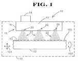
- FIG. 1is a general diagram illustrative of a medical device coating system, e.g., a nanoparticle generator system using electrospray techniques for coating surfaces, in accordance with the present invention.
- FIG. 2is a general diagram of an illustrative embodiment of a stent structure that can be coated according to the present invention.
- FIG. 3is a detailed portion of the stent structure of FIG. 2 coated according to one or more embodiments of the present invention.
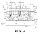
- FIG. 4is a general diagrammatical illustration of one embodiment of an electrospray dispensing device including multiple nozzle structures for use in a coating system shown generally in FIG. 1 .
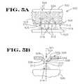
- FIGS. 5A and 5Bshow a general diagrammatical illustration and a more detail view of one portion thereof, respectively, of a configuration of providing multiple electrospray nozzle structures according to the present invention that may be employed in the coating system shown generally in FIG. 1 according to the present invention.
- FIGS. 6A and 6Bshow a general diagrammatical illustration and a more detail view of one portion thereof, respectively, of another alternate embodiment of a configuration for providing multiple electrospray nozzle structures that may be employed in the coating system shown generally in FIG. 1 according to the present invention.
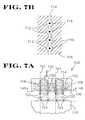
- FIGS. 7A and 7Bshow a general diagrammatical illustration and a more detail view of one portion thereof, respectively, of yet another alternate electrospray multiple nozzle structure that may be employed in the coating system shown generally in FIG. 1 according to the present invention.
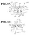
- FIGS. 8A and 8Bshow a general diagrammatical illustration and a more detail view of one portion thereof, respectively, of yet another alternate configuration of a multiple nozzle structure that forms cone jets for spraying particles using air as opposed to electrospray techniques and which may be employed in the medical device coating system of FIG. 1 according to the present invention.
- FIGS. 9A-9Eare a top view, a side view, and three additional more detailed views of portions shown in the top and side views, respectively.
- the figuresshow a holding fixture that may be employed in the medical device coating system shown generally in FIG. 1 according to the present invention; particularly, the holding structure is beneficial in holding a stent structure to be coated.
- FIGS. 10A and 10Bare a perspective view and a cross-section view of a portion thereof, respectively, of one illustrative embodiment of a medical device coating system employing multiple nozzle structures according to the present invention; the system being particularly beneficial in coating stent structures.
- FIGS. 11A and 11Bshow a perspective view and a cross-section view of a portion thereof, respectively, of another illustrative embodiment of a coating system employing multiple longitudinally configured nozzle structures according to the present invention; the system being particularly advantageous in coating stent structures.
- FIG. 12is a perspective view of yet another alternate illustrative embodiment of a coating system employing multiple radially configured nozzle structures according to the present invention; the system being particularly advantageous in coating stent structures.
- FIGS. 13A-13Cshow yet another alternate configuration of a medical device coating system according to the present invention.
- FIG. 13Ais a perspective view of the medical device coating system.
- FIG. 13Bis a cross-section view of a portion of the medical device coating system shown in FIG. 13A .
- FIG. 13Cis a more detailed view of a technique used during the coating process involving either electric field forces and/or mechanical forces such as those provided by air streams.
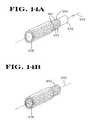
- FIGS. 14A and 14Bare perspective views used to illustrate a holding structure used during the coating of medical devices, particularly stent structures, according to the present invention.
- FIG. 15is a perspective view of yet another alternate configuration of a medical device coating system that may be employed for coating in the interior volume of a medical device (e.g., coating interior surfaces of a stent structure) according to the present invention.
- a medical devicee.g., coating interior surfaces of a stent structure
- FIGS. 16A and 16Bshow a perspective view and a cross-section view of a portion thereof, respectively, of another illustrative configuration of a medical device coating system that employs the use of a thermophoretic effect in coating a medical device according to the present invention.
- FIG. 1Various embodiments of the present invention shall then be described with reference to FIGS. 2-16 . It will become apparent to one skilled in the art that elements from one embodiment may be used in combination with elements of the other embodiments, and that the present invention is not limited to the specific embodiments described herein but only as described in the accompanying claims. For example, one or more different nozzle structures may be used for providing particles used in the coating methods and systems.
- the present inventionprovides for coated devices (e.g., coated stent structures) and also systems and methods for coating objects, such as medical devices. With use of the present invention, for example, coatings having uniform properties can be accomplished. Further, the present invention provides for the efficient and cost effective use of coating materials.
- the present inventionis directed to coating systems and methods that employ the generation of particles, such as, for example, nanoparticles, for use in coating objects.
- the present inventionis particularly advantageous in the coating of medical devices (e.g., coating such devices with DNA, RNA, coated DNA particles, etc.
- the systems and methods according to the present inventionmay use one or more single nozzle electrospray apparatus such as that previously described in U.S. Pat. No. 6,093,557 to Pui, et al., entitled “Electrospraying Apparatus and Method for Introducing Material into Cells,” issued 25 Jul.
- Patent Application US-2002-0007869-A1entitled “High Mass Throughput Particle Generation Using Multiple Nozzle Spraying,” published on 24 Jan. 2002, which are all hereby incorporated in their entirety by reference thereto.
- other apparatus for generating particlessuch as, for example, those described with reference to FIGS. 8A and 8B , may also be employed in one or more embodiments described herein.
- the present inventionprovides a medical device coating system 10 employing a dispensing apparatus 15 to establish one or more sprays of particles 22 (e.g., sprays of microdroplets which evaporate to form sprays of particles).
- the dispensing apparatus 15includes one or more nozzle structures 20 which receive source material 17 and establish sprays of particles 22 forward thereof, e.g., in the direction of medical device 12 .
- the particles 22are moved toward at least one surface 13 of the medical device 12 to form a coating 105 thereon.
- the medical device 12is preferably located in a defined volume (shown generally by the dashed line 11 ) where the particles 22 are provided.
- the defined volumemay, for example, be a reactor chamber, a chamber of a stent coating system, a volume formed by a body member (e.g., as described with reference to FIG. 10 ), a vacuum chamber, a pressurized and/or heated chamber, a volume of open air space, etc.
- the dispensing apparatus 15further includes a source holding apparatus 16 for providing the source material 17 to the plurality of nozzle structures 20 under control of control mechanism 14 , e.g. hardware and/or software control.
- control mechanism 14e.g. hardware and/or software control.
- Each of the one or more nozzle structures 20is configured to provide a spray of particles 22 to the defined volume 11 where the medical device is located. Generally, for example, in one or more embodiments, such spray of particles 22 established forward of each of the one or more nozzle structures 20 .
- the source material 17 held in the source holding apparatus 16may be any source of material which can be provided in the defined volume in particle form as described according to the present invention herein.
- the source material 17is a fluid composition that may include a solution, a suspension, a microsuspension, an emulsion, a microemulsion, a gel, a hydrosol, or any other fluid-like compositions that when provided according to the present invention results in the generation of particles.
- such fluid compositionsmay include a solution of dissolved active ingredients, e.g., drug active ingredients, according to one embodiment of the present invention.
- the source materialmay also be a dry material, e.g., material having substantially no solvent or liquid component associated therewith, as well.
- an active ingredientrefers to any component that provides a useful function when provided in particle form, particularly when provided as nanoparticles.
- the present inventionis particularly beneficial for spraying nanoparticles and also is particularly beneficial for spraying particles including biologically active ingredients.
- active ingredientrefers to material which is compatible with and has an effect on the substrate or body with which it is used, such as, for example, drug active ingredients, chemical elements for forming nanostructures, and elements for film coatings, e.g., polymers, excipients, etc.
- biologically active ingredient or “biologically active material or component”is a subset of active ingredient and refers to material which is compatible with and has an effect (which may, for example, be biological, chemical, or biochemical) on the animal or plant with which it is used and includes, for example, medicants such as medicines, pharmaceutical medicines, and veterinary medicines, vaccines, genetic materials such as polynucleic acids, cellular components, and other therapeutic agents, such as those described below.
- particleincludes solid, partially solid, and gel-like droplets and microcapsules which incorporate solid, partially solid, gel-like or liquid matter.
- Particles provided and employed hereinmay have a nominal diameter as large as 10 micrometers.
- nanoparticlerefers to a particle having a nominal diameter of less than 2000 nm.
- the present inventionis particularly beneficial in spraying nanoparticles having a nominal diameter greater than 1 nanometer (nm), and further preferably having a nominal diameter less than 1000 nm, and more preferably less than 100 nm.
- the particles used for coating medical devices described hereinare preferably monodisperse coating particles.
- monodisperse coating particlesare coating particles that have a geometrical standard deviation of less than 1.2. In other words, the standard deviation with respect to mean particle size of particles provided according to the present invention is preferably less than or equal to 20%.
- the method of coating at least a portion of a medical device 12(e.g., surface 13 of medical device 12 ) shall be described.
- the medical device 12is preferably positioned within the defined volume 11 (e.g., the defined volume 11 indicated generally by the dashed line that may be representative of a chamber or other structure encompassing one or more elements of the medical device coating system 10 ).
- the method of coating at least one surface thereofmay be initiated.
- a plurality of coating particles 22are provided in the defined volume 11 (e.g., monodisperse coating particles 22 ). The coating particles 22 are then moved towards at least one surface 13 of the medical device 12 to form a coating thereon.
- the coatingis represented generally as the dashed layer 105 .
- the coating particles 22may either be charged particles or uncharged particles.
- the coating particles 22are charged particles, preferably, highly charged particles.
- the coating particlesmay not need to be charged particles.
- uncharged particlesmay be provided using a dispensing apparatus such as that described with reference to FIGS. 8A and 8B , or, for example, electrosprayed according to the present invention and neutralized.
- the coating particles 22may be provided in the defined volume 11 prior to or simultaneously with the movement of the coating particles 22 towards the surface 13 of the medical device 12 .
- highly charged particlesmay be provided in the defined volume 11 prior to the establishment of an electric field utilized to move the coating particles 22 towards the surface 13 of the medical device 12 .
- an electric fieldmay be established between the medical device 12 and the dispensing apparatus 15 so as to simultaneously produce the particles 22 forward of the dispensing apparatus 15 and move such charged particles 22 towards surface 13 of the medical device 12 (e.g., an electrode may be positioned within an interior volume of the medical device 12 to establish an electric field between the medical device 12 and the dispensing apparatus 15 or the medical device 12 may be grounded to establish such an electric field therebetween).
- an electrodemay be positioned within an interior volume of the medical device 12 to establish an electric field between the medical device 12 and the dispensing apparatus 15 or the medical device 12 may be grounded to establish such an electric field therebetween).
- the medical device 12 and/or the dispensing apparatus 15may be moved in any one or more different directions as represented generally by the horizontal/vertical movement arrows 101 and radial movement arrow 102 prior to, during, or after the coating process for any particular reason.
- Such movement of the medical device 12 or any elements of the coating system 10may be performed using any apparatus configured for the desired motion.
- the present inventionis not limited to any particular structure for providing such movement. Further, the present invention is not limited to movement of any elements of the coating system 10 or the medical device 12 during the coating process. In other words, for example, the medical device 12 may remain in a fixed position within the defined volume 11 as the coating process is performed.
- the spray of particles 22 provided from the one or more nozzle structures 20are moved toward at least one surface 13 of the medical device 12 .
- Such particles 22are deposited onto the surface 13 for coating purposes.
- coatingrefers to forming a layer or structure on a surface.
- the coated layer or structure formed on the surfacemay be a coating that adheres to an underlying layer or the surface 13 , or a coating that does not adhere to the surface or an underlying layer. Any level of adherence to the surface 13 or an underlying layer is contemplated according to the present invention.
- a coating formed on surface 13 of the medical device 12may be formed as a sheath about a structure (e.g., a stent structure) without necessarily having adhesion between the layer and the medical device 12 .
- an adhesion layermay be deposited on a medical device 12 prior to forming a coating on the medical device 12 such that greater adhesion is accomplished.
- the adhesion layermay also be coated on the surface 13 of the medical device 12 employing method and/or systems according to the present invention.
- Various embodiments of the coating methods and systems describedare suitable to allow one or more medical devices to be coated as a batch.
- the present inventionis not limited to only coating medical devices in batches, i.e., coating a group of one or more devices in one batch process followed by coating a second group of one or more devices in a second batch process.
- the methods and systems of the present inventioncan be utilized to continuously run medical devices through the systems such that the process does not have to be started and stopped for coating the medical devices in batches. In other words, a plurality of medical devices can be coated through a continuous process.
- a coating sprayedmay include multiple coating materials, different nozzle structures may be provided with different source materials for controlling and spraying different coating materials, different nozzle structures may be controlled for use during different time periods so as to provide different layers of coating materials on at least a portion of the medical device, multiple layers may be sprayed using the same or different source materials (e.g., forming a somewhat laminated coating), the entire medical device or just a portion of the medical device may be coated (e.g., a charge could be applied to a portion of the surface to attract all of or a majority of the sprayed particles to the charged portion), different portions of the medical device may be sprayed with more coating materials than the remainder of the medical device, and/or masking materials may be used to mask certain portions of the medical device from having coating applied thereto.
- the present inventioncontemplates applying one layer or multiple layers of the same or different coating materials. Such, layers may perform identical or different functions (e.g., to provide for biocompatibility, to control drug release, etc.).
- the medical devices used in conjunction with the present inventioninclude any device amenable to the coating processes described herein.
- the medical device, or portion of the medical device, to be coated or surface modifiedmay be made of metal, polymers, ceramics, composites or combinations thereof, and for example, may be coated with one or more of these materials.
- glass, plastic or ceramic surfacesmay be coated.
- the present inventionmay be used to form a coating on surfaces of other objects as well, e.g., metal substrates or any other surfaces that may be rendered conductive (e.g., whether flat, curved, or of any other shape).
- vascular stentother medical devices within the scope of the present invention include any medical devices such as those, for example, which are used, at least in part, to penetrate and/or be positioned within the body of a patient, such as, but clearly not limited to, those devices that are implanted within the body of a patient by surgical procedures.
- Examples of such medical devicesinclude implantable devices such as catheters, needle injection catheters, blood clot filters, vascular grafts, stent grafts, biliary stents, colonic stents, bronchial/pulmonary stents, esophageal stents, ureteral stents, aneurysm filling coils and other coiled coil devices, trans myocardial revascularization (“TMR”) devices, percutaneous myocardial revascularization (“PMR”) devices, lead wires, implantable spheres, pumps, etc., as are known in the art, as well as devices such as hypodermic needles, soft tissue clips, holding devices, and other types of medically useful needles and closures.
- Any exposed surface of these medical devicesmay be coated with the methods and systems of the present invention including, for example, the inside exposed surface and the outside exposed surface of a tubular medical device which is open at both ends, e.g., a stent structure.
- the coating materials used in conjunction with the present inventionare any desired, suitable substances such as defined above with regard to active ingredients and biologically active ingredients.
- the coating materialscomprise therapeutic agents, applied to the medical devices alone or in combination with solvents in which the therapeutic agents are at least partially soluble or dispersible or emulsified, and/or in combination with polymeric materials as solutions, dispersions, suspensions, lattices, etc.
- therapeutic agentsand “drugs”, which fall within the biologically active ingredients classification described herein, are used interchangeably and include pharmaceutically active compounds, nucleic acids with and without carrier vectors such as lipids, compacting agents (such as histones), virus, polymers, proteins, and the like, with or without targeting sequences.
- the coating on the medical devicesmay provide for controlled release, which includes long-term or sustained release, of a bioactive material.
- therapeutic or biologically active ingredients used in conjunction with the present inventioninclude, for example, pharmaceutically active compounds, proteins, oligonucleotides, ribozymes, anti-sense genes, DNA compacting agents, gene/vector systems (i.e., anything that allows for the uptake and expression of nucleic acids), nucleic acids (including, for example, recombinant nucleic acids; naked DNA, cDNA, RNA; genomic DNA, cDNA or RNA in a non-infectious vector or in a viral vector which may have attached peptide targeting sequences; antisense nucleic acid (RNA or DNA); and DNA chimeras which include gene sequences and encoding for ferry proteins such as membrane translocating sequences (“MTS”) and herpes simplex virus-1 (“VP22”)), and viral, liposomes and cationic polymers that are selected from a number of types depending on the desired application.
- nucleic acidsincluding, for example, recombinant nucleic acids; naked DNA, cDNA, RNA
- biologically active solutesinclude anti-thrombogenic agents such as heparin, heparin derivatives, urokinase, and PPACK (dextrophenylalanine proline arginine chloromethylketone); prostaglandins, prostacyclins/prostacyclin analogs; antioxidants such as probucol and retinoic acid; angiogenic and anti-angiogenic agents; agents blocking smooth muscle cell proliferation such as rapamycin, angiopeptin, and monoclonal antibodies capable of blocking smooth muscle cell proliferation; anti-inflammatory agents such as dexamethasone, prednisolone, corticosterone, budesonide, estrogen, sulfasalazine, acetyl salicylic acid, and mesalamine, lipoxygenase inhibitors; calcium entry blockers such as verapamil, diltiazem and nifedipine; antineoplastic/antiproliferative/anti-mitotic agents such
- coating materials and/or additional coating materials for use in coating a medical device according to the present inventionare contemplated herein as would be apparent to one skilled in the art.
- coating materialsmay be provided in derivatized form or as salts of compounds.
- Polynucleotide sequences useful in practice of the inventioninclude DNA or RNA sequences having a therapeutic effect after being taken up by a cell.
- therapeutic polynucleotidesinclude anti-sense DNA and RNA; DNA coding for an anti-sense RNA; or DNA coding for tRNA or rRNA to replace defective or deficient endogenous molecules.
- the polynucleotides of the inventioncan also code for therapeutic proteins or polypeptides.
- a polypeptideis understood to be any translation product of a polynucleotide regardless of size, and whether glycosylated or not.
- Therapeutic proteins and polypeptidesinclude, as a primary example, those proteins or polypeptides that can compensate for defective or deficient species in an animal, or those that act through toxic effects to limit or remove harmful cells from the body.
- the polypeptides or proteins that can be incorporated into the polymer coating, or whose DNA can be incorporatedinclude without limitation, angiogenic factors and other molecules competent to induce angiogenesis, including acidic and basic fibroblast growth factors, vascular endothelial growth factor, hif-1, epidermal growth factor, transforming growth factor ⁇ and ⁇ , platelet-derived endothelial growth factor, platelet-derived growth factor, tumor necrosis factor ⁇ , hepatocyte growth factor and insulin like growth factor; growth factors; cell cycle inhibitors including CDK inhibitors; anti-restenosis agents, including p15, p16, p18, p19, p21, p27, p53, p57, Rb, nFkB and E2F decoys,
- MCP-1monocyte chemoattractant protein
- BMP'sthe family of bone morphogenic proteins
- the known proteinsinclude BMP-2, BMP-3, BMP-4, BMP-5, BMP-6 (Vgr-1), BMP-7 (OP-1), BMP-8, BMP-9, BMP-10, BMP-11, BMP-12, BMP-13, BMP-14, BMP-15, and BMP-16.
- BMP'sare any of BMP-2, BMP-3, BMP-4, BMP-5, BMP-6 and BMP-7.
- dimeric proteinscan be provided as homodimers, heterodimers, or combinations thereof, alone or together with other molecules.
- molecules capable of inducing an upstream or downstream effect of a BMPcan be provided.
- Such moleculesinclude any of the “hedgehog” proteins, or the DNA's encoding them.
- Coating materials other than therapeutic agentsinclude, for example, polymeric materials, sugars, waxes, and fats, applied alone or in combination with therapeutic agents, and monomers that are cross-linked or polymerized.
- Such coating materialsare applied in the form of, for example, powders, solutions, dispersions, suspensions, and/or emulsions of one or more polymers, optionally in aqueous and/or organic solvents and combinations thereof or optionally as liquid melts including no solvents.
- the polymeric materialsare optionally applied simultaneously with, or in sequence to (either before or after), the therapeutic agents.
- Such polymeric materials employed as, for example, primer layers for enhancing subsequent coating applicationse.g., application of alkanethiols or sulfhydryl-group containing coating solutions to gold-plated devices to enhance adhesion of subsequent layers
- layers to control the release of therapeutic agentse.g., barrier diffusion polymers to sustain the release of therapeutic agents, such as hydrophobic polymers; thermal responsive polymers; pH-responsive polymers such as cellulose acetate phthalate or acrylate-based polymers, hydroxypropyl methylcellulose phthalate, and polyvinyl acetate phthalate
- protective layers for underlying drug layerse.g., impermeable sealant polymers such as ethylcellulose
- biodegradable layerse.g., layers comprising albumin or heparin as blood compatible biopolymers, with or without other hydrophilic biocompatible materials of synthetic or natural origin such as dextrans, cyclodextrins, polyethylene oxide, and polyvinyl pyrrolidon
- the polymer coatingsmay include any material capable of absorbing, adsorbing, entrapping, or otherwise holding the therapeutic agent to be delivered.
- the materialis, for example, hydrophilic, hydrophobic, and/or biodegradable, and is preferably selected from the group consisting of polycarboxylic acids, cellulosic polymers, gelatin, polyvinylpyrrolidone, maleic anhydride polymers, polyamides, polyvinyl alcohols, polyethylene oxides, glycosaminoglycans, polysaccharides, polyesters, polyurethanes, silicones, polyurea, polyacrylate, polyacrylic acid and copolymers, polyorthoesters, polyanhydrides such as maleic anhydride, polycarbonates, polyethylene, polypropylenes, polylatic acids, polystyrene, natural and synthetic rubbers and elastomers such as polyisobutylene, polyisoprene, polybuta
- Coatings from polymer dispersionssuch as polyurethane dispersions (BAYHDROL, etc.) and acrylic latex dispersions are also within the scope of the present invention.
- Preferred polymersinclude polyurethanes; polyacrylic acid as described in U.S. Pat. No. 5,091,205; and aqueous coating compositions comprising an aqueous dispersion or emulsion of a polymer having organic acid functional groups and a poly-functional crosslinking agent having functional groups capable of reacting with organic acid groups, as described in U.S. Pat. No. 5,702,754.
- the release rate of drugs from drug matrix layersis largely controlled, for example, by variations in the polymer structure and formulation, the diffusion coefficient of the matrix, the solvent composition, the ratio of drug to polymer, potential chemical reactions and interactions between drug and polymer, the thickness of the drug adhesion layers and any barrier layers, and the process parameters, e.g., drying, etc.
- the coating(s) applied by the methods and apparatuses of the present inventionmay allow for a controlled release rate of a coating substance with the controlled release rate including both long-term and/or sustained release.
- the coating materialmay include suspended particles, e.g., a powder.
- the suspension particlesmay be fused to the surface of the medical device by an adhesion coating or some other technique such as electrostatic phenomena.
- coatings of the present inventionare applied such that they result in a suitable thickness, depending on the coating material and the purpose for which the coating or coatings are applied.
- coatings applied for localized drug deliveryare typically applied to a thickness of at least about 1 micron and not greater than 30 microns.
- the thicknessis greater than 2 microns.
- the thicknessis not greater than 20 microns.
- very thin coatingssuch as those as thin as 100 Angstroms may be provided. Much thicker coatings of more than 30 microns are also possible.
- the medical device 12is a stent structure.
- FIG. 2shows one illustrative exemplary embodiment of a stent structure 13 .
- Stent structure 13includes generally a cylindrical body of open framework material 21 extending along an axis 25 .
- the material forming the stent structure 13has openings 19 defined between portions of stent material 36 forming the structure 13 .
- Such open framework of material 21is shown generally in FIG. 2 and only indicates that typical stent structures include stent material and openings which form the structure.
- the present inventionis not limited to any particular stent construction.
- the stent structure 13extends along the axis 25 from a first open end 27 to a second open end 29 .
- the stent structure 13generally includes an exterior surface 33 of the stent material 36 which generally faces opposite an interior surface 31 of the stent structure 13 which defines an interior volume between the first open end 27 and second open end 29 thereof.
- FIG. 3generally shows an illustrative diagram of a portion of the stent structure 13 of FIG. 2 as coated using the present invention.
- the exterior surface 33 of the stent structure 13may be coated with one or more layers 37 .
- the interior surface 31 adjacent the interior volume of the stent structure 13may be coated with one or more coatings 23 .
- the exterior surface 33may be coated with an adhesion layer and one or more therapeutic agents.
- an anti-inflammatory therapeutic agentmay be the final layer formed on the exterior surface of the stent structure 13 .
- one or more layers 23may be formed on the interior surface 31 and may include, for example, an adhesion layer adjacent surface 31 with the final coating being in the form of an anti-coagulant biologically active ingredient.
- FIGS. 2 and 3are but one illustrative and diagrammatical example of a stent structure that may be coated according to the present invention.
- the variety of different stent structuresare numerous and coating of any and all such structures is contemplated according to the present invention (e.g., self expanding structures, structures formed of material not in the form of open framework material, etc.).
- the actual coating applied by the present inventionmay take the form of a multi-layered laminate-type structure that is adherent to one or more surfaces of the stent structure 13 without any adhesion layer.
- the nozzle structures 20 of the dispensing device 15may include nozzle structures having any one of various configurations and employing any number of different components, e.g., single and dual capillary electrodes, micro-machined tapered openings, etc.
- such nozzle structuresmay include one or more nozzle structures described in U.S. Pat. No. 6,093,557 or U.S. Patent Application US-2002-0007869-A1.
- Various types of nozzle structures, and dispensing devices with which they may be used,are shown and described herein.
- nozzle structures described in documents incorporated hereinmay provide further nozzle structures that may be used according to the present invention and/or may provide additional description regarding the nozzle structures that have also been described generally herein.
- FIG. 4shows one illustrative embodiment of an electrospray dispensing apparatus 52 that may be employed in the medical device coating system 10 such as shown generally in FIG. 1 .
- the electrospray dispensing apparatus 52includes one or more nozzle structures 54 for establishing a spray of charged particles 68 from each nozzle structure 54 .
- the electrospray dispensing apparatus 52includes a source material holding apparatus 60 for providing source material 77 to each of the nozzle structures 54 , e.g., simultaneously, for use in establishing the sprays of charged particles 68 .
- a single electrospray nozzle structurecan deliver a controlled feed rate of source material in the establishment of a spray of particle 68 within the envelope of the nozzle structure.
- This feed rate of source materialcan be increased by using the multiple nozzle structures 54 bundled together in one or more various configurations. For example, the feed rate may be increased by “n” times with “n” nozzle structures.
- the present inventionas described further below, enables the employment of as few as one nozzle structure and as many as, for example, 1,000 nozzle structures, e.g., capillary tubes, within a small area, e.g., seven or ten centimeter diameter.
- One of various challenges in spraying highly charged nanoparticles from a tightly packed bundle of nozzle structuresis to overcome the space charge effect of the nanoparticles from one nozzle structure on other adjacent nozzle structures.
- the voltage required to form a cone jet mode for a nozzle structure 54increases with decreasing internozzle distance.
- it is preferable to operate at a lower voltagebecause higher voltages may cause arcing between nozzle structures and a second electrode used to form the electric field; such arcing being problematic. Therefore, it may be desirable to have a multiple nozzle structure configuration that can have nozzle structures spaced close together with less internozzle distance, but which does not require a high voltage to establish the cone jet.
- each nozzle structure 54e.g., a capillary tube 59 , defines an opening 53 extending along an axis 51 and terminating at dispensing end 69 .
- the opening 53has a cross-section orthogonal to and centered on the axis 51 .
- internozzle distance (L)is defined as the distance between the center axis 51 of nozzle structures 54 .
- the voltage required to obtain a cone jet operationvaries based on internozzle distance. Generally, in one embodiment, the voltage required to obtain cone jet operation for a single capillary tube 59 is about 7500 volts. As the internozzle distance (L) decreases, a higher voltage is required to “expel” the highly charged nanoparticles away from the nozzle structure 54 to form the cone jet mode required for spraying nanoparticles. Ultimately, the required voltage reaches the breakdown electric field (approximately 18,000 volts) which defines the closest distance for the internozzle spacing.
- the internozzle distance (L)is also affected by the critical dimension (CD) of the opening 53 , e.g., the diameter of cross-section of the opening 53 orthogonal to the axis 51 of the nozzle structure 54 .
- CDcritical dimension
- capillaries 59are provided along the axis 51 of the nozzle structure 54 with each capillary terminating at a dispensing end 69 .
- the CD for the nozzle structure 54is the diameter of the opening 53 , i.e., the diameter of the cross-section of the opening from which spray is established at the dispensing end 69 .
- the ratio of the internozzle distance (L) to CDi.e., L/CD, is equal to or greater than 2.
- the ratio of the internozzle distance (L) to the diameter of the opening 53 orthogonal to axis 51is equal to or greater than 2.
- Each of the nozzle structures 54 of the electrospray dispensing device 52provides a charged spray with a high concentration of charged particles.
- concentration of charged particles in the sprayis in the range of about 10 5 particles per cubic centimeter (particles per cc) to about 10 12 particles/cc. Due to the space charge effect, i.e., the effect created by the charge repulsion of charged particles, a spray of substantially dispersed particles having the same polarity charge is provided with the particles distributed substantially uniformly across the spray area, as shown in FIG. 4 .
- substantially dispersed particlesrefers to uniformly and/or nonuniformly sized particles separated by an applied repulsive electrostatic force.
- the electrospray processis a consistent and reproducible transfer process.
- the charged particles of the sprayrepel one another, agglomeration of the particles is avoided. This results in a more uniform particle size.
- “Substantially dispersed” particlesis not to be confused with monodisperse particles which involves the general degree of uniformity of the particles sprayed, e.g., the standard deviation of the particles from a nominal size.
- the chargeis applied by concentration of charge on the spray of particles through evaporation of solution including the material, e.g., active ingredient, in an established electrical field 79 .
- the source material 77may be a suspension of active ingredients or a solution including dissolved active ingredients.
- the suspension or solutionis then dispensed from the electrospray dispensing device 52 , e.g., active ingredient of microdroplets are dispensed.
- the liquid sprayedgenerally evaporates to concentrate a charge of a liquid portion thereof on the particles, e.g., active ingredient particles, in the fluid composition or suspension being sprayed. This results in the spray of charged particles 68 as described further below.
- FIG. 4generally shows a diagrammatical illustration of the operation of the electrospray dispensing apparatus 52 for establishing charge sprays 68 from each of the nozzle structures 54 .
- Each of the nozzle structures 54receives a flow of fluid composition from the material source holding apparatus 60 .
- the material source holding apparatus 60may include a fluid composition 77 suspending drug active ingredients or having active ingredients dissolved therein.
- a conductive material 56positions each of the nozzle structures 54 in a particular configuration.
- the conductive material 56is adapted to be connected to a high voltage source 73 .
- Each of the nozzle structures 54includes a conductive structure, e.g., a capillary tube 59 as illustratively shown in FIG. 4 , defining an orifice, e.g., an opening 53 (e.g., a capillary tube opening or an orifice defined in a flooding type chamber, etc.) for receiving a flow of fluid composition 77 therein.
- the source material holding apparatus 60may be used according to the present invention, preferably a single holding apparatus is used to feed fluid composition 77 to one or more of the nozzle structures 54 .
- a single holding apparatusis used to feed fluid composition 77 to one or more of the nozzle structures 54 .
- any number of different and separate holding apparatusmay be used or hold various different fluid compositions and provide different compositions to different nozzle structures 54 .
- the fluid composition 77may be pushed or pulled through the opening 53 and provided at dispensing end 69 of the nozzle structure 54 , e.g., pushed by a pump.
- a compressed gas source represented generally by arrow 64e.g., an inert source that is non-reactive with the fluid composition 77 , is provided to compress the fluid composition 77 and force fluid to flow through openings 53 of the nozzle structures 54 .
- a compressed gas source 64is used to provide such fluid composition flow, other methods of providing such flow may also be used.
- a plate above the fluid composition 77 having a force, e.g., pneumatic force, applied theretomay be used, or syringe pumps for each nozzle structure may be used.
- the nozzle structures 54 positioned by and electrically coupled to the conductive structure 56function as a first electrode of the electrospray dispensing device 52 with the dispensing ends 69 of each nozzle structure being positioned for dispensing charged microdroplets toward medical device 12 , or a surface 13 thereof.
- the medical device 12functions as a second electrode structure, e.g., a grounded medical device 12 as shown by ground 81 .
- An electrical potential differenceis applied between the first electrode conductive structure 56 and the second electrode or grounded medical device 12 that is electrically isolated from the first electrode.
- the electrodesmay be formed using one or more conductive elements, and such electrodes may take one of various different configurations.
- a flow of the fluid composition 77is provided through the openings 53 of the nozzle structures 54 , e.g., pushed and/or pulled through the openings 53 .
- a meniscusis formed at the dispensing end 69 where the opening 53 has a diameter in the preferred range of about 6 microns to about 2 millimeters.
- a potential differenceis applied to establish a nonuniform field 79 between the first electrode conductive structure 56 electrically coupled to the nozzle structures 54 and the second electrode (e.g., the medical device 12 ) connected to ground 81 .
- a high positive voltagemay be applied to the first electrode conductive structure 56 with the second electrode medical device 12 being grounded.
- a voltage difference that provides an electric field intensity of greater than 4 kV/cmis preferably used.
- nonuniform electric fieldrefers to an electric field created by an electrical potential difference between two electrodes.
- the nonuniform electric fieldincludes at least some electric field lines that are more locally concentrated at one electrode relative to the other electrode, e.g., more concentrated at the dispensing end 69 relative to the second electrode or a grounded medical device 12 .
- at least some of the field linesare off axis relative to the longitudinal axis 51 through the center of the opening 53 .
- the grounded medical device 12is positioned forward of dispensing end 69 and is of a size and/or includes at least a portion that is located at a position away from the longitudinal axis 51 .
- the second electrodemay be one or more ring electrodes, plate electrodes, grounded medical device surfaces, etc. The medical device 12 may still be coated even if a different electrode structure is used to produce the charged particles.
- a ring electrodemay be positioned forward of the dispensing end 69 to create the electric field for providing highly charged particles in the defined volume in which the medical device is positioned.
- another electrical fieldmay be created to move the highly charged particles toward a grounded medical device.
- coating the medical device 12 using the coating system 10 shown generally in FIG. 1may involve providing particles in a defined volume in which the medical device is provided, and thereafter, moving the particles toward the medical device for forming a coating thereon.
- the particlesmay be formed and moved toward the medical device for coating thereon simultaneously with their formation.
- the medical devicemay be grounded to set up the uniform field for producing the charged particles in the defined volume in which the medical device is provided with the field also providing for the movement of such charged particles towards the medical device 12 so as to form a coating thereon.
- the fluid composition 77is flowed through the opening 53 of the nozzle structures 54 .
- the fluid composition 77 provided to the opening 53has an electrical conductivity.
- the potential difference between the first and second electrodes which creates the electric field therebetweenstrips the liquid of one polarity of charge, i.e., the negative charge is stripped when a high positive voltage is applied to the electrode 56 , leaving a positively charged microdroplet to be dispensed from the dispensing end 69 .
- the meniscus at the dispensing end 69may form a cone jet for dispensing a spray of microdroplets including the active ingredients when forces of a nonuniform field balance the surface tension of the meniscus.
- the spray of microdropletsfurther become more positive in a nonuniform electric field.
- the charge of the microdropletsconcentrate on the active ingredients resulting in a spray of charged particles.
- the amount of charge on the microdroplet, and thus the amount of charge on a particle after evaporation,is based at least upon the conductivity of the fluid composition used to spray the microdroplet, the surface tension of the fluid composition, the dielectric constant of the fluid composition, and the feed flow rate thereof.
- the electric charge concentrated on a particular particleis greater than about 30% of a maximum charge that can be held by the microdroplets, without the microdroplet being shattered or torn apart, i.e., greater than about 30% of the Rayleigh charge limit.
- the chargeis greater than 50% of the Rayleigh charge limit.
- the surface tension of the microdropletis overcome by the electric forces causing droplet disintegration.
- the nonuniform electric fieldalso provides for containment of particles and/or direction for the particles which would otherwise proceed in random directions due to the space charge effect.
- the voltages appliedmay be reversed.
- the first electrodemay be grounded with a high positive voltage applied to the second electrode.
- the particleswould have a negative charge concentrated thereon.
- any other applied voltage configurationproviding a nonuniform electric field to establish the charged spray of particles may be used.
- the second electrodemay be any conductive material grounded and positioned to establish the formation of a spray 68 from the dispensing ends 69 of the nozzle structures 54 , e.g., the second electrode may be a grounded ring electrode, a grounded elongated element positioned in the interior volume of a stent structure, etc.
- the second electrodemay also be located at various positions, such as just forward of the nozzle structures 54 , or located farther away from the nozzle structures 54 and closer to medical device 12 .
- the strength of the fieldmay be adjusted by adjustment of the distance between the first and second electrodes. Different field strengths may result in relatively different areas D upon which particle spray is provided, at least in part due to the space charge effect of the sprays of particles 68 .
- one or more components of the dispensing apparatus 52may be moved relative to the others, e.g., the medical device relative to the one or more nozzle structures 54 or vice versa, to facilitate adjustment of field strength.
- the fluid composition 77 from the holding apparatus 60is provided to the nozzle structures 54 , when operable, under control of, preferably, compressed gas source 64 .
- the flowmay also be controlled with use of a liquid pump (e.g., a syringe pump, a gravity feed pump, a pressure regulated liquid reservoir, etc.), a mass flow controller, or any other flow control devices suitable for feeding source material, e.g., fluid composition 77 , to the one or more nozzle structures 54 as would be known to one skilled in the art.
- the flow of fluid compositionis atomized into microdroplets by the dispensing device 52 .
- Atomizationmay be provided by any known technique for producing microdroplets, which microdroplets preferably have a nominal diameter of about 10 nanometers or greater, more preferably about 20 nanometers to about 10 micrometers, and even more preferably about 30 nanometers to about 1 micrometer.
- electrostatic atomizationis used.
- other atomization devicese.g., pressure regulated atomizers, ultrasonic nebulizers, hydraulic nozzles, etc.
- microdroplets having nominal diameters in the range of about 10 nanometers to about 2 micronscan be produced by electrospray.
- a high positive voltage 73 applied to the capillary tube electrodes via the conductive structure 56 with the grounding of the second electrode medical device 12provides sprays 68 with a relatively high positive charge.
- the second electrode 12in such a case may be provided to ground 81 or may have a negative voltage connected thereto.
- the voltage appliedis limited by the maximum electric field intensity permitted in the medium in which the field is created. For example, arcing will occur in air at an electrical field intensity greater than about 30 kV/cm.
- the allowed electric field intensitycan be increased with use of a sheath gas about the nozzle structures, such as CO 2 , SF 6 , etc.
- pulsating modes or cone jet modes of operationare achieved.
- a cone jet mode of operationa cone shaped liquid meniscus is formed at the dispensing end 69
- the shape of a liquid meniscusalternates between a cone shape and a round shape.
- a spray from a cone jet 83 formed at the orifice or opening 53 of the capillary tube 59is preferred.
- the dispensing apparatus 52preferably includes capillary tubes 59 made of a suitable material, such as, for example, platinum, silica, etc., for providing the spray 68 from each of the nozzle structures 54 , e.g., the capillary tube 59 thereof.
- the capillary tubemay have an outer diameter in the preferred range of about 6 micrometers to about 2.5 millimeters and an inner diameter in the preferred range of about 6 micrometers to about 2 millimeters.
- the dispensing apparatus 52may include a casing about each capillary tube, e.g., a concentric tube, or about the dispensing apparatus 52 , e.g., a housing surrounding the spraying portion of the apparatus 52 , which may be used to provide a sheath of gas, e.g., CO 2 , SF 6 , etc., around the capillary tubes 59 to increase the electrostatic breakdown voltage for the capillary tubes, e.g., to prevent corona discharge.
- a sheath of gasis particularly beneficial when the spray is created using a high surface tension liquid, e.g., deionized water.
- the nonuniform electric fieldprovides for containment of particles and/or direction for the particles which would otherwise proceed in random directions due to the space charge effect; the space charge effect being necessary to provision of monodisperse and nonconglomerated particles.
- the space charge effectis generally dependent upon the size of the particles and the charge thereon.
- the concentration of the particles in the defined volumecan be controlled with only adequate coating material being present which is to deposited on the medical device.
- the quantity of coating materiale.g., DNA or RNA
- the electric fielddirects the particles towards the medical device 12 and prevents the particles from depositing on structures surrounding the medical device, e.g., walls of a chamber in which the medical device is positioned, and other structures that may be used in the coating of the medical device such as apparatus associated with the movement of the medical device 12 , e.g., either longitudinally or radially.
- the coating material system 10is configured such that prior to contact with the at least one surface 13 of the medical device 12 , a residual particle volume occupied by the evaporated microdroplet includes less than about 20% of a solvent component of the microdroplet sprayed from the dispensing apparatus. However, preferably, some solvent component forms a part of the residual particle volume as the particle contacts the surface 13 of the medical device 12 . With some solvent component being a part of the residual particle volume occupied by the evaporated microdroplet, adhesion of the microdroplet (including the particle) to the surface 13 of the medical device 12 may be enhanced.
- the remainder portion of the solventevaporates, leaving the particle coated on the surface 13 of the medical device 12 .
- the residual particle volume occupied by the evaporated microdropletincludes some solvent component but less than about 20% of a solvent component contained in the originally sprayed microdroplet.
- the amount of evaporation prior to the microdroplet/particle contacting the surface 13 of the medical device 12may be controlled in any number of different ways.
- the evaporationmay be controlled by the type of solvent used, the distance between the dispensing apparatus and the medical device, the temperature and pressure of a chamber in which the medical device is provided, the size of the microdroplet, etc.
- the present inventionis not limited to any particular method of controlling such evaporation, and various other methods will be apparent to those skilled in the art.
- the various configurationsmay include the use of a single capillary tube, multiple capillary tubes bundled in one or more different configurations such as, for example, a pentagon shape, hexagon shape, or other spatial configurations as described in U.S. Patent Application US-2002-0007869-A1, published on 24 Jan. 2002.
- capillary tubesmade of a suitable material, such as, for example, platinum, silicon, etc., may be used for providing sprays of particles as described herein.
- a suitable materialsuch as, for example, platinum, silicon, etc.
- capillary tubesare tapered at the tips thereof so as to concentrate the electric field at the tip of each capillary.
- capillary tubesmay include the use of a single capillary tube as well as dual concentric capillary tubes, such as described in the above-mentioned U.S. Patent Application, US-2002-0007869-A1.
- dual streams of liquidsmay be provided from a concentric dual opening capillary dispensing end for establishing a spray from the dispensing apparatus.
- a dual capillary configurationmay be used to spray coated particles of active ingredients or create particles having more than one ingredient.
- active ingredientsmay be provided by a first fluid composition through a first opening and a coating material, e.g., a time release polymer, may be provided by a second fluid composition through a second opening.
- the coating materialmay encapsulate the active ingredient, at least in part, and the coated particles are then transported for forming a layer on the medical device 12 .
- such a dual capillary configurationmay be used to control conductivity of the particle being sprayed by changing the electrical conductivity of one or more of the liquids being sprayed (e.g., increasing the conductivity of one of the compositions being sprayed such that a higher charge is concentrated on the particle during evaporation).
- the fluidsmay also have a different surface tension.
- a fluidmay be flowed through a center capillary with the other fluid being provided in the space between the center capillary and a concentric capillary as described in U.S. Patent Application, US-2002-0007869-A1.
- hard to spray fluids through the center capillarycan be provided at the dispensing ends of the center and concentric capillary.
- Such sprayingis facilitated by, for example, the additional conductivity of the fluid (e.g., an alcohol) in the space surrounding the center capillary such that additional charge is concentrated on the particles sprayed through the center capillary.
- the sprayingis also assisted by the surface tension differences between the fluids as they meet at the dispensing end of the dual capillary configuration to form the cone jet for spraying the fluid through the center capillary.
- the dual capillary configurationmay be used with any type of source material.
- the fluidsmay be active ingredients, biologically active ingredients, excipients, or any other source materials such as those described herein.
- the outer fluidmay be in a gas form to assist in forming a cone jet or providing components for use in spraying material from the center capillary.
- a gasmay also be provided by the center capillary with a fluid provided in the space between the center and concentric capillaries.
- particles having voids at the centermay be formed.
- Such a particle defining a void, e.g., a bubble,may be beneficial in, for example, a situation where surface area is desired but the quantity of ingredient forming the larger surface area is to be kept to a minimum.
- capillary-type nozzle structuresas various suitable nozzle structures may be employed.
- various other nozzle structuresare described generally herein. Any nozzle structure suitable to provide a spray of particles according to the principles described herein may be used, e.g., slits that may provide various cone jets (e.g., with or without posts as described herein), nozzle structures having portions thereof that are integral with portions of other nozzle structures, nozzle structures that form a part of a chamber wall in which a medical device is positioned, radially or longitudinally configured slots such as described herein with particular reference to coating stent structures as shown in FIGS. 11-13 , multiple opening nozzle structures (e.g., micromachined nozzle structures that each have dual openings like that of the dual capillary configuration), etc.
- the nozzle structuresmay be provided using a configuration shown in FIGS. 5A and 5B .
- An electrospray dispensing apparatus 502that may be employed in the medical device coating system of FIG. 1 includes one or more nozzle structures 506 .
- the nozzle structures 506are provided, preferably, by a single integral conductive material 504 , e.g., a micro-machined plate.
- the conductive material or micro-machined plate 504may form a part, e.g., the bottom surface 523 , of fluid composition holding apparatus 522 for containing fluid composition 524 and providing a flow of fluid composition 524 to each of the nozzle structures 506 .
- a compressed gas source 526may be used to deliver the fluid composition 524 to each orifice or opening 525 of the nozzle structures 506 .
- cone jets 517are provided at dispensing ends 513 of the one or more nozzle structures 506 to provide the sprays of particles 519 (e.g., microdroplets that evaporate and concentrate charge on the contained particles used to coat the medical device).
- FIG. 5Bshows one of the nozzle structures 506 of FIG. 5A in further detail.
- the nozzle structure 506includes a tapered portion 516 that defines the orifice or opening 525 .
- the opening 525 of the nozzle structure 506extends along the axis 501 .
- the tapered portion 516includes tapered inner surfaces 509 , i.e., inner relative to the fluid composition, to receive fluid composition 524 and provide sufficient flow into opening 525 .
- the tapered portion 516further includes outer tapered surfaces 508 .
- the outer tapered surfaces 508 and inner tapered surfaces 509are preferably opposing surfaces having a generally parallel configuration.
- tapersare at the same angle relative to the generally plate-like conductive material 504 which lies orthogonal to axis 501 .
- the tapered outer surfaces 508extend towards the target 520 and terminate at dispensing end 513 at which a cone jet is formed when operating under the applied potential difference.
- FIGS. 6A and 6Bshow a diagrammatic illustration of another alternate embodiment of an electrospray dispensing apparatus 552 that includes one or more nozzle structures 556 in a similar manner to that shown in FIGS. 5A and 5B , but having a dual opening configuration.
- this apparatusmay be used in a manner similar to that described herein with respect to concentric capillaries and also as described in U.S. Patent Application, US-2002-0007869-A1.
- the dispensing apparatus 552includes generally two conductive plate-like structures 584 and 585 acting as the first electrode of the device 552 .
- the conductive plate-like structures 584 and 585are separated to allow for a fluid composition 573 to be provided therebetween from a fluid composition source 572 .
- the plate-like structures 584 and 585are formed to provide the dual opening nozzle structures 556 .
- Each of the nozzle structures 556form a cone jet 560 upon application of a suitable potential difference between the first electrode, i.e., the conductive plate structures 584 and/or 585 and the medical device 554 .
- a spray of particles 562is provided or established at the dispensing ends 582 (see FIG. 6B ) of each nozzle structure 556 .
- fluid composition 566 held in holding apparatus 564is provided for flow through each of the nozzle structures 556 .
- the fluid composition 566may be the same or different than the fluid composition 573 .
- the fluid composition 566is different than the fluid composition 573 .
- fluid composition 566may include an active ingredient for medicinal purposes and the fluid composition 573 may include an excipient or a coating material, such as a time release material, e.g., a polymer. With the use of such fluid compositions, coated particles can be sprayed from each nozzle structure 556 for use in coating the medical device 554 .
- FIG. 6Bshows a more detailed drawing of one nozzle structure 556 employed in the dispensing device 552 .
- first conductive plate structure 584provides for the definition of an opening 596 through which first fluid composition 566 is provided.
- the first conductive plate structure 584 and the second plate structure 585provide for a space or channel 570 therebetween to receive a second fluid composition 573 .
- the second fluid composition 573meets the first fluid composition 566 at opening 594 defined by the second conductive plate structure 585 .
- the two fluid compositionsmay come into contact with each other in either the channel 570 or the opening 594 .
- the first conductive plate structure 584includes a tapered portion 586 that defines the opening 596 along axis 553 .
- the tapered portion 586includes inner tapered surfaces 598 , i.e., relative to fluid composition 566 , that receive fluid composition 566 , and outer surfaces 597 tapered in a manner, preferably like those of inner surfaces 598 .
- the outer surfaces 597extend towards the medical device 554 and terminate at an outlet 574 into channel 570 .
- conductive plate structure 585includes tapered portion 588 which defines opening 594 along axis 553 .
- the tapered portion 588includes inner surfaces 591 that receive the second fluid composition 573 and the first fluid composition 566 provided via outlet 574 .
- the tapered portion 588further includes outer tapered surfaces 590 that terminate at dispensing end 582 such that when a potential difference is applied between the conductive plate structures 585 , 588 and the medical device 554 , a cone jet 560 is formed at the dispensing end 582 .
- each of the nozzle structuresmust include a protrusion from a plate-like structure.
- the tapered portions of the nozzle structure shown in FIGS. 5-6which provide a protrusion or extension from such plates are required to allow for the formation of a cone jet at the tip of such protruding structures.
- the openingsmay take the form of a small capillary tube type opening or may take the form of an elongated opening (i.e., a slot).
- the openings 506 and 556may take the form of elongated openings such as shown in the embodiments for coating a stent structure.
- FIG. 11uses elongated longitudinal slots that are positioned parallel to an axis along which the stent structure is located. A plurality of the longitudinal slots are located radially about the axis. Radially configured slots are shown in FIG. 12 . Such radially configured slots are formed at a distance radially from the axis along which the stent structure is located. A plurality of the radially configured slots (e.g., arcs) are spaced along the axis.
- the particles, e.g., nanoparticles of the sprays established at the dispensing ends of the nozzle structuresare generally highly charged which occurs because of an increasingly higher voltage potential applied to the nozzle structure to operate in cone jet mode. Because of the increasingly higher voltage potential, eventually, a corona discharge and voltage breakdown may occur and destroy the cone jet. As shown in FIG. 6A , it is possible to use a separation structure, e.g., structure 558 , to isolate each nozzle structure from adjacent nozzle structures to reduce the space charge effect caused by the highly charged nanoparticles. This separation structure technique provides one method of allowing the nozzle structures to be highly packed into a small region.
- separation structure 558may be used.
- separation structures extending from a plateare provided between each of the capillaries and may be used as described in U.S. Patent Application, US-2002-0007869-A1.
- any form or size of such separation structuremay be used as long as suitable isolation of the dispensing ends from each other is provided.
- the separation structuresextend to a point lower than the dispensing end or, in the conjunction with the use of capillaries, the tips thereof. In such a manner, a cone jet is allowed to form at the dispensing end of each nozzle structure.
- the separation structuremay be made of any insulative material, such as Teflon, plastic, etc. Because the space charge effect is reduced by the separation structure, i.e., the space charge effect between nozzle structures, a more uniform dispersed spray of particles is provided. This is in part due to the lower voltage operation allowed with the use of such separation structure.
- the configuration of the separation structurewill be, at least in part, dependent upon the structure or configuration of the nozzle structures. In other words, if a rectangular pattern of nozzle structures is utilized, then line type separators may be used. Likewise, if a circular configuration of nozzle structures is used, then such separators may need to be in a type of circular configuration.
- Separation structuresare shown in FIG. 6A .
- Such separation extensions 558are shown as extending from conductive plate structure 585 to separate the nozzle structures 556 .
- separation extensions 512extend from conductive plate structure 504 to separate the nozzle structures 506 .
- FIGS. 7A and 7BAnother alternate dispensing device 700 is shown in FIGS. 7A and 7B .
- axial posts 716are used to guide liquid flow. Cone jet formation is facilitated by having the guided post 716 at the center of the cone jet 720 .
- FIG. 7Ashows an exemplary side view of the dispensing device 700 and
- FIG. 7Bshows a cross-section of FIG. 7A at line 7 B- 7 B.
- the dispensing device 700includes a conductive plate 706 having multiple openings 712 , e.g., circular openings, formed therein for use in providing multiple nozzle structures 708 .
- Each opening 712 and the conductive plate 706generally lie orthogonal to axes 701 of the nozzle structures 708 .
- such openingsmay be connected by channel portions 714 .
- Each of the nozzle structures 708is formed using one of the openings 712 by providing a post member 716 , e.g., a solid post, along the axis 701 through the center of the opening 712 .
- the post member 716includes a tip 721 that extends a predetermined distance past the conductive plate 706 and through the opening 712 to form the nozzle structure 708 .
- the plate structure 706may form a part of fluid composition holding apparatus 704 in which fluid composition 702 is contained.
- the fluid composition 702As the fluid composition 702 is pushed through openings 712 forming part of the nozzle structure 708 , by or under control of, for example, a compressed gas source 730 , the fluid composition 702 follows the post 716 .
- cone jets 720With the appropriate pressure applied by gas source 730 and an electrical potential difference applied between the plate 706 and medical device 710 , cone jets 720 are formed at the tips 721 of the post members 716 . Sprays of particles 722 are then provided as a result of the cone jets.
- the particles in one or more embodiments of the medical device coating system 10 according to the present inventionmay be provided in one or more different manners according to the present invention.
- charged particlesare provided by an electrospray apparatus.
- the particlesdo not need to be charged particles.
- thermophoretic effectmay be used to move coating particles towards the medical device 12 for coating a surface 13 thereof.
- an alternative to providing a cone jet by electrostatic forceis used to form the cone jet.
- the alternative techniqueuses an aerodynamic force to provide the cone jet for spraying the particles.
- FIGS. 8A and 8Bshow an air dispensing apparatus 800 that employs the use of aerodynamic force in the formation of a cone jet which may be employed in the general embodiment of the medical device coating system shown in FIG. 1 .
- the air dispensing apparatus 800includes a plate 840 having openings 842 formed therein for use in providing multiple nozzle structures 806 .
- the multiple nozzle structures 806 of the air dispensing device 800are provided by positioning a capillary 812 with an end 815 thereof in close proximity to the opening 842 in the plate 840 .
- the capillary 812generally lies orthogonal to the plate 840 .
- a cone jet 831can be formed at the dispensing end 810 of the nozzle structure 806 to provide a spray of particles 808 from each nozzle structure 806 that can be moved toward the medical device 804 to form a coating thereon.
- a fluid composition 822 held in holding apparatus 820is provided into the capillaries 812 under control of, for example, compressed gas source 824 .
- a gas source 830e.g., preferably a compressed gas source, provides compressed gas 830 around the dispensing tip 815 of capillary 812 and through opening 842 of each nozzle structure 806 .
- the cone jet modeis provided at the dispensing end 810 of each of the nozzle structures by the compressed gas 830 flowing through opening 842 and around the capillary tube tip 815 as further described below with reference to FIG. 8B .
- FIG. 8Bshows a more detailed diagram of each nozzle structure 806 of the air dispensing apparatus 800 .
- the capillary tube 812includes a body portion 813 and the tip 815 .
- the tip 815is slightly tapered.
- the plate 840which has the openings 842 defined therein, includes a tapered region 839 defining each opening 842 .
- the tapered region 839includes inner surfaces 841 , i.e., inner relative to the compressed gas 830 , provides for receiving the compressed gas 830 and applying aerodynamic force onto the meniscus of fluid composition 822 formed at capillary tube tip 815 .
- the cone jet 831is formed thereby which provides the spray of particles 808 .
- tapered portion 839may take one of various configurations.
- such tapered surfaces 841may include multiple tapers or may be arced, or further, may even include multiple tapered inner and outer surfaces as previously described herein with reference to FIGS. 5-6 .
- capillariesmay be used to provide the fluid composition in close proximity to the opening for 842.
- a capillary tube 812 having a tip 815 thereof positioned below the upper surface 837 and in the opening 842 defined in the plate 840is employed.
- Aerodynamic cone jetshave been shown to produce particles having a size as small as 70 microns.
- such cone jetsare described in the article entitled “New Microfluidic Technologies to Generate Respirable Aerosols for Medical Application,” by Afonso M. Ganan-Calvo, Journal of Aerosol Science, Vol. 30, Suppl. 1, pps. 541-542.
- the dual structuresmay be implemented using the aerodynamic structures shown in FIGS. 8A and 8B , as well.
- multiple openingsmay be provided for each nozzle structure in a manner similar to that shown in FIGS. 8A and 8B .
- coated particlesmay be generated thereby.
- the present inventionis particularly advantageous in coating medical devices such as stent structures (e.g., a stent structure such as that shown generally and diagrammatically in FIG. 2 ).
- FIGS. 9A-9Eshow a holding fixture for use in coating such a stent structure.
- various embodiments of at least portions of coating systemsare described with reference to FIGS. 10-16 .
- Such systemsare particularly beneficial in coating stent structures but may also be used in coating other medical devices such as those previously described herein.
- FIG. 9Ashows a top view of a holding fixture 200 for holding a stent 204 adjacent a dispensing apparatus 202 (e.g., a single or multiple capillary tube electrospray apparatus).
- a dispensing apparatus 202e.g., a single or multiple capillary tube electrospray apparatus.
- the stent 204is separated from the holding fixture 200 but would be placed on the holding fixture 200 in the region 203 when the coating method is being performed.
- the holding fixture 200functions to not only hold the stent structure 204 , but also to ground the stent structure 204 .
- FIG. 9Bshows a side view of the holding fixture 200 with the stent structure 204 apart from the apparatus 200 .
- the holding fixture 200includes an elongated holding structure 206 .
- the holding structure 206includes a pin holding spindle element 220 as further shown in greater detail in the detailed side view of FIG. 9C .
- the spindle element 220e.g., a stainless steel spindle, includes a body member 205 that extends along axis 211 from a threaded first end 223 to a second end 225 .
- the threaded first end 223 of the spindle element 220is coupled to a corresponding threaded element 210 that is affixed to a platform 201 . All the elements of the holding fixture 200 are mounted, either directly or indirectly, to the platform 201 .
- the spindle element 220is moveably mounted by moveable holding elements 208 (e.g., bearing structures) to allow for rotation of the spindle holding element 220 .
- Rotation of the spindle element 220is implemented by a coupling element 216 which couples the spindle element 220 to a motor 212 .
- the motor 212drives a shaft 217 that is connected via a belt or gear (not shown) to the spindle element 220 at notch 227 (see FIG. 9C ).
- radial motion of spindle element 220is effected.
- the spindle element 220rotates within the holding elements 208 . Rotation is permitted by the rotation of threaded first end 223 within the threaded element 210 mounted to the platform 201 .
- the shaft 217is moveable in a longitudinal direction along axis 250 .
- Axis 250lies substantially parallel to axis 211 .
- Such longitudinal motion along axis 250is translated through the coupling structure 216 to the spindle element 220 effecting motion along axis 211 .
- the spindle element 220is allowed to move in such a longitudinal manner through openings of holding elements 208 .
- the spindle element 220can be rotated (i.e., radial motion about axis 211 ) as well as provided with movement along axis 211 .
- the speed of such rotation and longitudinal motioncan also be controlled.
- any type of structure providing such longitudinal and/or radial motionmay be used according to the present invention and that the present invention is not limited to this particular structure.
- an elongated opening 243is defined at the second end 225 of the spindle element 220 .
- the opening 243is sized for receiving a pin holding structure 230 .
- the pin holding structure 230is shown in further detail in FIG. 9D and generally includes a pin elongated body member 263 that extends from a first end 241 along axis 211 (when mounted) to a second end 257 .
- the pin elongated body member 263is a conductive elongated body member (e.g., a tungsten pin member).
- the pin elongated body member 263may be modified with narrow circumferential rings of conductive or non-conductive material to provide horizontal support for stents of increasing length. Further, the pin elongated body member 263 may also be made non-conductive, so that the stent itself is the only grounded feature in the spray path.
- the elongated opening 243 of the spindle element 220lies along axis 211 and is configured to receive the first end 241 of the pin holding structure 230 and hold the pin holding structure 230 in the elongated opening 243 .
- a slot 245is provided to accept a clip for holding the pin holding structure 230 within the elongated opening 243 at the second end 225 of the spindle element 220 .
- the pin holding structure 230includes a tube element 261 sized to be received over the pin elongated body member 263 .
- the tube element 261e.g., a nonconductive tube element
- the tube 261is inserted over the pin elongated body member 263 of the pin holding structure 230 and thereafter the pin elongated body member 263 and tube element 261 is inserted through the interior volume of the stent structure 204 such that the interior surface of the stent structure 204 is positioned adjacent to the tube element 261 .
- the pin holding structure 230further includes a retaining structure 253 at the second end 257 thereof.
- the retaining structure 253includes a tapered region 267 (e.g., an electrically conductive portion) for engaging and for use in grounding the stent as further described below.
- the retaining structure 253need only be larger than the stent structure 204 to retain the stent structure on the pin holding structure 230 and include at least a conductive portion which can be used to ground the stent structure 204 .
- the interior surface of stent structure 204is adjacent the nonconductive elongated tube 261 .
- the open end 269e.g., a tapered end
- the nonconductive tube 261e.g., Teflon elongated tube
- the stent structure 204is forced to come in contact with the tapered surfaces 267 of the retaining structure 253 . With the stent structure 204 in contact with the conductive material of the retaining structure 253 , and the retaining structure 253 in electrical contact with the conductive pin elongated body element 263 , the stent structure 204 is easily grounded.
- the dispensing apparatus 202may provide a plurality of particles for coating the stent structure 204 .
- the longitudinal and radial motion of spindle element 220can be provided for rotating and moving the stent structure 204 radially and longitudinally.
- the timing of the rotation of the stent structure 204 about axis 211 and the longitudinal movement of the stent structure 204 along axis 211can be controlled to coat the stent structure 204 in a single pass.
- the concentration of coating particles in the region 203can also be controlled to achieve such single pass coating.
- one or more passesmay also be utilized to provide one or more coating layers and/or to provide a laminated type coating on the stent structure 204 .
- the holding fixture 200is but one exemplary embodiment of a holding fixture that can be used to locate a stent structure at a particular position during a coating process according to the present invention.
- Various other holding structures or components thereofare described herein.
- the present inventionis not to be taken as being limited to any of the specifically described configurations but only as described in the accompanying claims.
- FIG. 10Aillustratively shows a perspective view of a stent coating system 350 for coating one or more stent structures 340 .
- FIG. 10Bshows a cross-sectional view of a portion of the system 350 .
- the coating system 350includes a body member 358 , preferably a cylindrical body member that extends along an axis 345 therethrough.
- nozzle structures 362Provided at the interior of the cylindrical body member 358 are nozzle structures 362 positioned radially about and also longitudinally along the axis 345 .
- the nozzle structures 362may be configured as capillary tubes, or may be micro-machined openings such as described herein, or may include any other type of nozzle structures suitable for providing particles according to the present invention.
- the nozzle structures 362are preferably configured at the inner surface 359 of the body member 358 .
- the stent structures 340are held within the body member 358 with the axis 345 coinciding with an axis of the stent structures 340 .
- Any one of a number of different types of holding structures or techniquesmay be used.
- Various holding structures and techniquesare described herein. However, the present invention is not limited to any particular holding structure but is only limited as described in the accompanying claims.
- the stent structures 340include an open framework of stent material 341 .
- stent material 341includes openings 342 between one or more portions thereof.
- the stent structures 340With the stent structures 340 positioned within the body member 358 , the stent structures 340 are grounded as shown by the illustrative grounding symbol 373 in FIG. 10B . With the stent structures 340 grounded and a high voltage 353 applied to the nozzle structures 362 , coating material from a coating material source (e.g., a coating material reservoir 357 ) may be provided such that an electrospray of particles is established within the interior volume of the body member 358 . With such particles provided, the electric field between the nozzle structures 362 and the stent structures 340 provide for the movement of the charged particles to form a coating on the stent structures 340 .
- a coating material sourcee.g., a coating material reservoir 357
- nozzle structures 362 and other nozzle structures in the following embodimentsmay take the form of any one or more of the various different types of nozzle structure configurations described herein. Further, such nozzle structures may be operated in any of the manners as described herein.
- the reservoir for holding the coating material in the various embodiments hereinmay take one of various different types of configurations.
- the reservoirmay be a concentric cylindrical holding chamber for the source material as well as any other different type of configuration with operational elements for providing a feed of the source material to the one or more nozzle structures.
- operational elementsfor providing a feed of the source material to the one or more nozzle structures.
- pressuremay be applied to the source material, various gas streams may be used to assist in providing such source material, etc.
- FIGS. 11A and 11Bshow a perspective view and a cross-section view of another stent coating system 450 according to the present invention.
- the coating system 450includes a body member 458 , preferably a cylindrical body member, extending along axis 445 .
- the cylindrical body member 458includes longitudinal slots in the body member 458 that extend parallel to axis 445 .
- the longitudinal slotsare located in a radial manner about the axis 445 to provide particles within the interior volume 459 of the cylindrical body member 458 .
- a stent structure 440is positioned within the body member 458 with its axis coincident with axis 445 .
- the stent structure 440is held in place by an elongated element 446 (e.g., a wire) with a plug at each end 475 to hold the stent structure 440 in position.
- the longitudinal slots 470are preferably equally spaced about the body member 458 . As such, each dispensing end of the longitudinal slot 470 is generally of equidistance to the stent structure 440 .
- FIG. 11Bshows an illustrative cross-section view of FIG. 11A taken at line 11 B- 11 B.
- the cross-section illustrationshows a reservoir 457 for holding the coating material that is provided for the spray of particles through the longitudinal slots 470 of the coating system 450 .
- the stent structure 440is grounded, as shown schematically by ground 473 , with the nozzles being held at a high voltage 471 to establish the electric field between the nozzle structures 470 and stent structure 440 .
- ground 473ground 473
- FIG. 12shows yet another alternate portion of a medical device coating system 650 which is substantially similar to that shown in FIGS. 11A and 11B with a cylindrical body member 658 extending along axis 645 .
- the stent coating system 650includes radially configured slots 670 .
- the radial slots 670are configured at a radial distance about axis 645 .
- a plurality of the radial slots 670are positioned in a direction along the axis 645 .
- the openings of the nozzle structures formed by the radial slots 670are equidistant from the stent structure 640 .
- the radially configured slot configurationmay include multiple arc sections of nozzle structures that substantially extend along the entire circumference of the inner surface 659 of the body member 658 or, alternatively, such arc sections may only partially extend along a radial circumference of the inner surface 659 . As shown in FIG. 12 , two arc sections are configured along the inner circumference on inner surface 659 of the body member 658 .
- FIGS. 13A-13Cillustrate yet another exemplary portion of a stent structure coating system 850 according to the present invention.
- the body member 858includes longitudinal slots 870 located parallel to axis 845 and spaced radially about the axis 845 . This configuration is essentially the same as described with reference to FIGS. 11A and 11B . However, various embodiments of holding a stent structure 840 to be coated located with its axis coincident with axis 845 are shown in FIGS. 13A-13C .
- one or more additional body members 880may be positioned along the axis 845 such that the stent structure 840 may be coated with one type of particles in the body member 858 and yet another type of particles in the body member 880 .
- the body member 880may be configured with nozzle structures (not shown) configured in any manner such as those described herein (e.g., the same or different nozzle structures than used for body member 858 ).
- an elongated support element 857is used to assist in the coating process and hold the stent structure 840 in position.
- the stent 840is positioned with its axis coincident with axis 845 along which the elongated body member 858 extends. Also extending along the axis 845 with its axis coincident with the axis 845 of the stent structure 840 is an elongated support element 857 .
- the elongated support element 857is positioned in the interior of the stent structure 840 .
- an electric field 891exists for moving the particles toward the stent structure 840 as shown in FIG. 13C .
- an additional high voltage 863 applied to elongated support wire 857 that is conductivean additional field 893 providing a force opposite to that of electric field 891 is produced.
- the stent structure 840is held in a particular position.
- it is possible to control the coating processsuch that the particles to be coated on the stent structure 840 are substantially maintained on the outer surface of stent structure 840 to form a coating 861 thereon.
- this configuration of opposing fieldsprovides not only for the maintenance of the stent structure 840 in a stable position along the elongated support wire 857 but also operates to provide the coating particles about the outer surface of the stent structure 840 . As such, the interior surfaces thereof are maintained substantially free of coating material. In certain circumstances, a sheath may even be provided over the stent structure. In other words, not only is the stent structure material of the open framework of material coated with the coating material, but the openings of the open framework material may also having coating material formed thereover to form the sheath. Additional sheath formation will further be described with reference to FIGS. 14A and 14B .
- the forces generated by the opposing electric fieldsmay also be provided using other mechanical force techniques.
- the elongated support element 857may be a porous capillary that provides an air stream within the body member 858 .
- the air streamprovides the force opposing that of the electrical field used to move the particles towards the stent structure 840 . Further, the air stream may be used to maintain the stent structure in a stable position.
- FIGS. 14A and 14Bfurther show a holding structure for holding a stent during a coating process.
- an elongated element 935e.g. a wire or tube
- the elongated element 935preferably is made of a nonconductive material such as Teflon.
- the coating 938may be formed not only on the stent material 941 but may also cover openings 942 in the open framework of stent material 941 .
- the element 935may be removed, leaving the coated stent structure as partially cut-away and shown in FIG. 14B .
- the element 935may be expanded to provide for stretching of the stent material when positioned within the interior volume of the stent structure 940 (e.g., the Teflon tube as shown in the embodiment of FIG. 9 ). Thereafter, after the coating 938 is applied on the stretched stent structure 948 , the force expanding the elongated element 935 may be released and the element 935 removed. The stent structure 940 may then collapse slightly.
- the stent structure 940e.g., the Teflon tube as shown in the embodiment of FIG. 9 .
- Each of the methods of holding the stent structures in position along the axis of the coating systemis constructed to prevent the stent structure 940 from sagging.
- the middle of the stent structurei.e., the midpoint between a first and second end of the stent structure
- gravitymay also prevent sagging.
- inner surfaces defining interior volumes of stent structuresmay also be advantageously coated according to the present invention.
- FIG. 15a coating system for coating an interior surface 939 of a stent structure 940 that defines an interior volume thereof is illustrated.
- the coating system shown in FIG. 15is essentially the same as that shown in FIGS. 11A and 11B for coating the outer surface of the stent structure 440 .
- an elongated nozzle structuree.g., a capillary tube 900
- the stent structure 440is grounded, as schematically shown by grounding element 473 .
- grounding element 473With the high voltage applied to the capillary tube 900 , an electric field is established between the interior surface 939 of stent structure 440 and the capillary tube 900 to form a cone jet and provide a spray of particles 910 into the interior volume of the stent structure 440 .
- the capillary tube 900is preferably sized to be insertable within the stent structure 440 . Further, the capillary tube 900 and/or the stent structure 440 can be moved along the axis 445 to provide a uniform spray on the interior surface 939 thereof.
- FIG. 15illustrates a single nozzle structure in the form of a capillary 900 providing a spray 910 of particles to coat the interior surface 939 , one skilled in the art will recognize that an elongated structure having multiple nozzles yet sized to be received within the stent structure may also be used. Further, any nozzle configuration described herein may also be used to coat the interior surface 939 .
- an elemente.g., a tube element
- an elementmay be positioned about the outer surface of the stent structure to hold the stent structure 440 in place during the interior surface coating process shown in FIG. 15 .
- coatingmay be prevented from deposition on the exterior surface with use of such an element.
- an interior sheathmay be formed on the interior surface.
- thermophoretic effectmay also be used to move such particles towards a stent structure 940 as shown and illustrated in FIGS. 16A and 16B .
- thermophoretic forcesare used to move particles 962 provided in the interior volume 959 of a body member 958 toward the stent structure 940 .
- thermophoretic forcedenotes the thermal force that is acting on a particle as a result of a temperature gradient associated with the surrounding environment.
- the effect of this temperature gradient on a given particlemay be understood by considering the molecular forces impinging on the particle. Those molecules which strike the particle from a high temperature impart a greater impulse to the particle than those molecules which strike the particle from the low temperature side.
- concomitant radiation effectsmay augment these molecular forces.
- the particlefeels a net force directing it from the hotter temperature zone to the cooler temperature zone. This is the thermophoretic effect referred to herein.
- the coating system 950includes the body member 958 that extends along axis 955 and is held at a higher temperature than an elongated element 980 that extends through the stent structure 940 (e.g., an element that may be or may not be in contact with the interior surface of the stent structure 940 ).
- the stent structure 940is held such that its axis is coincident with axis 955 .
- a temperature gradientis established and the particles are moved towards the colder elongated element 980 as is shown in the cross-section view of FIG. 16B .
- a coating 982is formed on the outer surface of the stent structure 940 .
- the stent structure 940may be held within the body member 958 using any means previously described herein or any other configuration which preferably holds it at an equidistance from the heated portions of the body member 958 .
- the temperature gradientis preferably kept equivalent about the stent structure 940 in a radial fashion.
- the elongated element 980is sized such that it is in contact with the inner surface of a stent structure 940 .
- an effective temperature gradientcan be established and particles are prohibited from depositing on the inner surface of the stent structure.
- sagging of the stent structurecan be reduced.
Landscapes
- Health & Medical Sciences (AREA)
- Life Sciences & Earth Sciences (AREA)
- Public Health (AREA)
- Veterinary Medicine (AREA)
- Epidemiology (AREA)
- Surgery (AREA)
- Animal Behavior & Ethology (AREA)
- General Health & Medical Sciences (AREA)
- Heart & Thoracic Surgery (AREA)
- Vascular Medicine (AREA)
- Chemical & Material Sciences (AREA)
- Engineering & Computer Science (AREA)
- Biomedical Technology (AREA)
- Medicinal Chemistry (AREA)
- Molecular Biology (AREA)
- Application Of Or Painting With Fluid Materials (AREA)
- Media Introduction/Drainage Providing Device (AREA)
- Materials For Medical Uses (AREA)
Abstract
Description
Claims (78)
Priority Applications (1)
| Application Number | Priority Date | Filing Date | Title |
|---|---|---|---|
| US11/390,606US8028646B2 (en) | 2001-05-16 | 2006-03-28 | Coating medical devices |
Applications Claiming Priority (3)
| Application Number | Priority Date | Filing Date | Title |
|---|---|---|---|
| US09/858,865US6764720B2 (en) | 2000-05-16 | 2001-05-16 | High mass throughput particle generation using multiple nozzle spraying |
| US10/301,473US7247338B2 (en) | 2001-05-16 | 2002-11-21 | Coating medical devices |
| US11/390,606US8028646B2 (en) | 2001-05-16 | 2006-03-28 | Coating medical devices |
Related Parent Applications (1)
| Application Number | Title | Priority Date | Filing Date |
|---|---|---|---|
| US10/301,473DivisionUS7247338B2 (en) | 2001-05-16 | 2002-11-21 | Coating medical devices |
Publications (2)
| Publication Number | Publication Date |
|---|---|
| US20060177573A1 US20060177573A1 (en) | 2006-08-10 |
| US8028646B2true US8028646B2 (en) | 2011-10-04 |
Family
ID=32392393
Family Applications (2)
| Application Number | Title | Priority Date | Filing Date |
|---|---|---|---|
| US10/301,473Expired - LifetimeUS7247338B2 (en) | 2001-05-16 | 2002-11-21 | Coating medical devices |
| US11/390,606Expired - Fee RelatedUS8028646B2 (en) | 2001-05-16 | 2006-03-28 | Coating medical devices |
Family Applications Before (1)
| Application Number | Title | Priority Date | Filing Date |
|---|---|---|---|
| US10/301,473Expired - LifetimeUS7247338B2 (en) | 2001-05-16 | 2002-11-21 | Coating medical devices |
Country Status (6)
| Country | Link |
|---|---|
| US (2) | US7247338B2 (en) |
| EP (1) | EP1581278B1 (en) |
| JP (1) | JP2006511259A (en) |
| AU (1) | AU2003295583B2 (en) |
| CA (1) | CA2506966A1 (en) |
| WO (1) | WO2004047882A2 (en) |
Cited By (15)
| Publication number | Priority date | Publication date | Assignee | Title |
|---|---|---|---|---|
| US20120098416A1 (en)* | 2010-10-26 | 2012-04-26 | Sung-Hwan Cho | Apparatus for forming thin layer, method of manufacturing organic light-emitting display apparatus using the same and organic light-emitting display apparatus manufactured using the method |
| US20130045335A1 (en)* | 2008-06-23 | 2013-02-21 | Cornell Univeristy | Multiplexed Electrospray Deposition Apparatus |
| US8535358B2 (en) | 2007-11-19 | 2013-09-17 | Medical Facets, Llc | Bone screw and method for manufacturing the same |
| US8685070B2 (en) | 2007-11-19 | 2014-04-01 | Medical Facets, Llc | Faceted bone screw |
| US20150136869A1 (en)* | 2013-11-15 | 2015-05-21 | Akita Epson Corporation | Droplet oscillation device and droplet oscillation method |
| US9050611B2 (en) | 2000-05-16 | 2015-06-09 | Regents Of The University Of Minnesota | High mass throughput particle generation using multiple nozzle spraying |
| US9114413B1 (en)* | 2009-06-17 | 2015-08-25 | Alessandro Gomez | Multiplexed electrospray cooling |
| WO2017027742A1 (en) | 2015-08-11 | 2017-02-16 | Akeso Biomedical, Inc. | Biofilm inhibiting compositions enhancing weight gain in livestock |
| CN107115982A (en)* | 2017-06-06 | 2017-09-01 | 西安航天动力研究所 | A kind of injection apparatus for low-viscosity (mobile) liquid space environment drop formation |
| CN107638984A (en)* | 2017-11-20 | 2018-01-30 | 无锡杰森表面处理设备有限公司 | The small vehicle seat of metal tube paint spraying and baking |
| CN107649316A (en)* | 2017-11-20 | 2018-02-02 | 无锡杰森表面处理设备有限公司 | The rotary paint spraying apparatus of metal pipe material |
| US9961886B2 (en) | 2014-08-13 | 2018-05-08 | Akeso Biomedical, Inc. | Antimicrobial compounds and compositions, and uses thereof |
| EP3473188A1 (en) | 2012-02-13 | 2019-04-24 | Medical Facets LLC | Faceted bone screw |
| WO2019136150A1 (en) | 2016-02-17 | 2019-07-11 | Akeso Biomedical, Inc. | Biofilm inhibiting compositions enhancing weight gain in livestock |
| EP3530226A1 (en) | 2012-02-09 | 2019-08-28 | Orthopedic Medical Channels, LLC | Bone screw and method for manufacturing the same |
Families Citing this family (250)
| Publication number | Priority date | Publication date | Assignee | Title |
|---|---|---|---|---|
| US6433154B1 (en) | 1997-06-12 | 2002-08-13 | Bristol-Myers Squibb Company | Functional receptor/kinase chimera in yeast cells |
| US6306166B1 (en)* | 1997-08-13 | 2001-10-23 | Scimed Life Systems, Inc. | Loading and release of water-insoluble drugs |
| US7713297B2 (en) | 1998-04-11 | 2010-05-11 | Boston Scientific Scimed, Inc. | Drug-releasing stent with ceramic-containing layer |
| US20020161376A1 (en)* | 2001-04-27 | 2002-10-31 | Barry James J. | Method and system for delivery of coated implants |
| US8889169B2 (en)* | 2001-05-11 | 2014-11-18 | Exogenesis Corporation | Drug delivery system and method of manufacturing thereof |
| US7923055B2 (en) | 2001-05-11 | 2011-04-12 | Exogenesis Corporation | Method of manufacturing a drug delivery system |
| US7666462B2 (en)* | 2001-05-11 | 2010-02-23 | Exogenesis Corporation | Method of controlling a drug release rate |
| US7247338B2 (en)* | 2001-05-16 | 2007-07-24 | Regents Of The University Of Minnesota | Coating medical devices |
| US6669980B2 (en)* | 2001-09-18 | 2003-12-30 | Scimed Life Systems, Inc. | Method for spray-coating medical devices |
| AU2002348033B2 (en) | 2001-10-23 | 2008-05-29 | Covidien Lp | Surgical fasteners |
| US7682387B2 (en)* | 2002-04-24 | 2010-03-23 | Biosensors International Group, Ltd. | Drug-delivery endovascular stent and method for treating restenosis |
| US6939376B2 (en) | 2001-11-05 | 2005-09-06 | Sun Biomedical, Ltd. | Drug-delivery endovascular stent and method for treating restenosis |
| US7105175B2 (en)* | 2002-06-19 | 2006-09-12 | Boston Scientific Scimed, Inc. | Implantable or insertable medical devices for controlled delivery of a therapeutic agent |
| US7550004B2 (en)* | 2002-08-20 | 2009-06-23 | Cook Biotech Incorporated | Endoluminal device with extracellular matrix material and methods |
| US7338557B1 (en)* | 2002-12-17 | 2008-03-04 | Advanced Cardiovascular Systems, Inc. | Nozzle for use in coating a stent |
| US7628859B1 (en)* | 2002-12-27 | 2009-12-08 | Advanced Cardiovascular Systems, Inc. | Mounting assembly for a stent and a method of using the same to coat a stent |
| US6803070B2 (en)* | 2002-12-30 | 2004-10-12 | Scimed Life Systems, Inc. | Apparatus and method for embedding nanoparticles in polymeric medical devices |
| EP1462801A3 (en)* | 2003-03-24 | 2005-01-05 | Tepnel Lifecodes | Methods for determining the negative control value for multi-analyte assays |
| CN102794256B (en)* | 2003-05-27 | 2014-12-10 | 松下电器产业株式会社 | Method and apparatus for creating environment where mist of charged water particle is dispersed |
| US20040260384A1 (en)* | 2003-06-17 | 2004-12-23 | Medtronic Ave | Superelastic coiled stent |
| US7341630B1 (en) | 2003-06-26 | 2008-03-11 | Advanced Cardiovascular Systems, Inc. | Stent coating system |
| US8801692B2 (en)* | 2003-09-24 | 2014-08-12 | Medtronic Vascular, Inc. | Gradient coated stent and method of fabrication |
| US7441513B1 (en)* | 2003-09-26 | 2008-10-28 | Advanced Cardiovascular Systems, Inc. | Plasma-generated coating apparatus for medical devices and a method of coating deposition |
| US7198675B2 (en) | 2003-09-30 | 2007-04-03 | Advanced Cardiovascular Systems | Stent mandrel fixture and method for selectively coating surfaces of a stent |
| EP1526214A1 (en)* | 2003-10-21 | 2005-04-27 | Materials Technics Holding Société Anonyme | Process and device for impreganting a fibre network with powder material in an electrostatic field with alternating current |
| US7252746B2 (en)* | 2003-11-12 | 2007-08-07 | Cook Incorporated | Electropolishing apparatus and method for medical implants |
| US7241344B2 (en)* | 2004-02-10 | 2007-07-10 | Boston Scientific Scimed, Inc. | Apparatus and method for electrostatic spray coating of medical devices |
| US8137397B2 (en)* | 2004-02-26 | 2012-03-20 | Boston Scientific Scimed, Inc. | Medical devices |
| US7335264B2 (en)* | 2004-04-22 | 2008-02-26 | Boston Scientific Scimed, Inc. | Differentially coated medical devices, system for differentially coating medical devices, and coating method |
| WO2005102101A1 (en)* | 2004-04-23 | 2005-11-03 | Matsushita Electric Works, Ltd. | Fan heater with electrostatic atomizer |
| US9498563B2 (en)* | 2004-04-23 | 2016-11-22 | Boston Scientific Scimed, Inc. | Medical articles having therapeutic-agent-containing regions formed from coalesced polymer particles |
| US7553377B1 (en)* | 2004-04-27 | 2009-06-30 | Advanced Cardiovascular Systems, Inc. | Apparatus and method for electrostatic coating of an abluminal stent surface |
| US8293890B2 (en)* | 2004-04-30 | 2012-10-23 | Advanced Cardiovascular Systems, Inc. | Hyaluronic acid based copolymers |
| US20060002594A1 (en)* | 2004-06-09 | 2006-01-05 | Clarke Allan J | Method for producing a pharmaceutical product |
| US8101244B2 (en)* | 2004-06-09 | 2012-01-24 | Smithkline Beecham Corporation | Apparatus and method for producing or processing a product or sample |
| TWI356036B (en)* | 2004-06-09 | 2012-01-11 | Smithkline Beecham Corp | Apparatus and method for pharmaceutical production |
| US20060002986A1 (en)* | 2004-06-09 | 2006-01-05 | Smithkline Beecham Corporation | Pharmaceutical product |
| DE102004038396A1 (en)* | 2004-08-06 | 2006-03-30 | Lothar Sellin | Device (I), for coating medicinal products, comprises equipment for producing ultrasound and a vacuum chamber containing retaining means for one or more medicinal products |
| AR043476A1 (en)* | 2004-09-09 | 2005-08-03 | Dvoskin Victor Oscar | REGULATED SUBSTANCE ADMINISTRATION DEVICE FOR INSERTION IN A BODY CAVITY AND PROCEDURE FOR MANUFACTURING A SUPPORT MEDIA FOR SUCH SUBSTANCES |
| US7845536B2 (en) | 2004-10-18 | 2010-12-07 | Tyco Healthcare Group Lp | Annular adhesive structure |
| US7938307B2 (en) | 2004-10-18 | 2011-05-10 | Tyco Healthcare Group Lp | Support structures and methods of using the same |
| US20060083859A1 (en)* | 2004-10-20 | 2006-04-20 | Todd Robida | Magnetic levitation system for coating a device, a method of using the system, and device made by the system |
| US7892592B1 (en)* | 2004-11-30 | 2011-02-22 | Advanced Cardiovascular Systems, Inc. | Coating abluminal surfaces of stents and other implantable medical devices |
| US20060127443A1 (en)* | 2004-12-09 | 2006-06-15 | Helmus Michael N | Medical devices having vapor deposited nanoporous coatings for controlled therapeutic agent delivery |
| US20060198942A1 (en)* | 2005-03-04 | 2006-09-07 | O'connor Timothy | System and method for coating a medical appliance utilizing a vibrating mesh nebulizer |
| US9364229B2 (en) | 2005-03-15 | 2016-06-14 | Covidien Lp | Circular anastomosis structures |
| US20060216431A1 (en)* | 2005-03-28 | 2006-09-28 | Kerrigan Cameron K | Electrostatic abluminal coating of a stent crimped on a balloon catheter |
| US20060279807A1 (en)* | 2005-06-08 | 2006-12-14 | Chun-Hsiang Kung | Flat bed scanner |
| US20070003291A1 (en)* | 2005-06-09 | 2007-01-04 | Kasper Bryon L | Distortion cancellation in a transimpedance amplifier circuit |
| US20090062909A1 (en) | 2005-07-15 | 2009-03-05 | Micell Technologies, Inc. | Stent with polymer coating containing amorphous rapamycin |
| WO2007011707A2 (en) | 2005-07-15 | 2007-01-25 | Micell Technologies, Inc. | Polymer coatings containing drug powder of controlled morphology |
| US20070077435A1 (en)* | 2005-10-05 | 2007-04-05 | Schachter Deborah M | Process for coating a medical device |
| WO2007042133A1 (en)* | 2005-10-10 | 2007-04-19 | Brandenburgische Technische Universität Cottbus | Extensional flow layer separating reactor |
| CN100453188C (en)* | 2005-10-14 | 2009-01-21 | 鸿富锦精密工业(深圳)有限公司 | Equipment for depositing carbon nanotube films |
| US8834912B2 (en)* | 2005-12-30 | 2014-09-16 | Boston Scientific Scimed, Inc. | Medical devices having multiple charged layers |
| US9108217B2 (en) | 2006-01-31 | 2015-08-18 | Nanocopoeia, Inc. | Nanoparticle coating of surfaces |
| US7951428B2 (en)* | 2006-01-31 | 2011-05-31 | Regents Of The University Of Minnesota | Electrospray coating of objects |
| EP1988941A2 (en) | 2006-01-31 | 2008-11-12 | Nanocopoeia, Inc. | Nanoparticle coating of surfaces |
| US7981479B2 (en)* | 2006-02-17 | 2011-07-19 | Howmedica Osteonics Corp. | Multi-station rotation system for use in spray operations |
| US7836847B2 (en)* | 2006-02-17 | 2010-11-23 | Howmedica Osteonics Corp. | Multi-station rotation system for use in spray operations |
| US8211168B2 (en) | 2006-02-21 | 2012-07-03 | Cook Biotech Incorporated | Graft material, stent graft and method |
| US20080138374A1 (en)* | 2006-02-27 | 2008-06-12 | Storey Daniel M | Molecular Plasma Deposition of Bioactive Small Molecules |
| US7250195B1 (en)* | 2006-02-27 | 2007-07-31 | Ionic Fusion Corporation | Molecular plasma deposition of colloidal materials |
| US20070224235A1 (en) | 2006-03-24 | 2007-09-27 | Barron Tenney | Medical devices having nanoporous coatings for controlled therapeutic agent delivery |
| US8187620B2 (en) | 2006-03-27 | 2012-05-29 | Boston Scientific Scimed, Inc. | Medical devices comprising a porous metal oxide or metal material and a polymer coating for delivering therapeutic agents |
| US7758908B2 (en)* | 2006-03-28 | 2010-07-20 | Boston Scientific Scimed, Inc. | Method for spray coating a medical device using a micronozzle |
| US20070237802A1 (en)* | 2006-04-11 | 2007-10-11 | Medtronic Vascular, Inc. | Inhibition of Calcification on an Endovascular Device |
| EP2944382A1 (en) | 2006-04-26 | 2015-11-18 | Micell Technologies, Inc. | Coatings containing multiple drugs |
| US20070254091A1 (en)* | 2006-04-28 | 2007-11-01 | Boston Scientific Scimed, Inc. | System and method for electrostatic-assisted spray coating of a medical device |
| US8003156B2 (en)* | 2006-05-04 | 2011-08-23 | Advanced Cardiovascular Systems, Inc. | Rotatable support elements for stents |
| US8815275B2 (en) | 2006-06-28 | 2014-08-26 | Boston Scientific Scimed, Inc. | Coatings for medical devices comprising a therapeutic agent and a metallic material |
| WO2008002778A2 (en) | 2006-06-29 | 2008-01-03 | Boston Scientific Limited | Medical devices with selective coating |
| US9040069B2 (en)* | 2006-07-07 | 2015-05-26 | Biotronik Vi Patent Ag | Process for manufacturing a stationary state of crystalline polymer of a biodegradable polymer matrix carrying an active substance and a polymer matrix produced thereby |
| EP2068757B1 (en) | 2006-09-14 | 2011-05-11 | Boston Scientific Limited | Medical devices with drug-eluting coating |
| ES2357661T3 (en)* | 2006-09-15 | 2011-04-28 | Boston Scientific Scimed, Inc. | BIOEROSIONABLE ENDOPROOTHESIS WITH BIOESTABLE INORGANIC LAYERS. |
| US20080075753A1 (en)* | 2006-09-25 | 2008-03-27 | Chappa Ralph A | Multi-layered coatings and methods for controlling elution of active agents |
| US8636767B2 (en) | 2006-10-02 | 2014-01-28 | Micell Technologies, Inc. | Surgical sutures having increased strength |
| KR101518223B1 (en)* | 2006-10-19 | 2015-05-08 | 나노메크 인코포레이티드 | Methods and apparatus for making coatings using ultrasonic spray deposition |
| WO2008051433A2 (en) | 2006-10-19 | 2008-05-02 | The Board Of Trustees Of The University Of Arkansas | Methods and apparatus for making coatings using electrostatic spray |
| US9539593B2 (en) | 2006-10-23 | 2017-01-10 | Micell Technologies, Inc. | Holder for electrically charging a substrate during coating |
| US20080095953A1 (en)* | 2006-10-24 | 2008-04-24 | Samsung Electronics Co., Ltd. | Apparatus for depositing thin film and method of depositing the same |
| US7845533B2 (en) | 2007-06-22 | 2010-12-07 | Tyco Healthcare Group Lp | Detachable buttress material retention systems for use with a surgical stapling device |
| US20080281409A1 (en)* | 2006-11-03 | 2008-11-13 | Anthony Malone | Stents with drug eluting coatings |
| US20080294236A1 (en)* | 2007-05-23 | 2008-11-27 | Boston Scientific Scimed, Inc. | Endoprosthesis with Select Ceramic and Polymer Coatings |
| US7981150B2 (en)* | 2006-11-09 | 2011-07-19 | Boston Scientific Scimed, Inc. | Endoprosthesis with coatings |
| US7629030B2 (en)* | 2006-12-05 | 2009-12-08 | Nanostatics, Llc | Electrospraying/electrospinning array utilizing a replacement array of individual tip flow restriction |
| US9040816B2 (en)* | 2006-12-08 | 2015-05-26 | Nanocopoeia, Inc. | Methods and apparatus for forming photovoltaic cells using electrospray |
| US11426494B2 (en) | 2007-01-08 | 2022-08-30 | MT Acquisition Holdings LLC | Stents having biodegradable layers |
| EP2111184B1 (en) | 2007-01-08 | 2018-07-25 | Micell Technologies, Inc. | Stents having biodegradable layers |
| KR101198980B1 (en) | 2007-01-21 | 2012-11-07 | 헤모텍 아게 | Medical product for treating stenosis of body passages and for preventing threatening restenosis |
| WO2008094700A2 (en)* | 2007-01-31 | 2008-08-07 | Nanocopoeia, Inc. | Nanoparticle coating of surfaces |
| US20080199646A1 (en)* | 2007-02-15 | 2008-08-21 | Medtronic Vascular, Inc. | Inline Particle Deposition Extrusion |
| US8431149B2 (en)* | 2007-03-01 | 2013-04-30 | Boston Scientific Scimed, Inc. | Coated medical devices for abluminal drug delivery |
| US8070797B2 (en) | 2007-03-01 | 2011-12-06 | Boston Scientific Scimed, Inc. | Medical device with a porous surface for delivery of a therapeutic agent |
| EP3087929B1 (en) | 2007-03-06 | 2020-04-29 | Covidien LP | Surgical stapling apparatus |
| US8067054B2 (en) | 2007-04-05 | 2011-11-29 | Boston Scientific Scimed, Inc. | Stents with ceramic drug reservoir layer and methods of making and using the same |
| US9433516B2 (en) | 2007-04-17 | 2016-09-06 | Micell Technologies, Inc. | Stents having controlled elution |
| US7976915B2 (en) | 2007-05-23 | 2011-07-12 | Boston Scientific Scimed, Inc. | Endoprosthesis with select ceramic morphology |
| CA2688314C (en)* | 2007-05-25 | 2013-12-03 | Micell Technologies, Inc. | Polymer films for medical device coating |
| US7665646B2 (en) | 2007-06-18 | 2010-02-23 | Tyco Healthcare Group Lp | Interlocking buttress material retention system |
| US9192697B2 (en) | 2007-07-03 | 2015-11-24 | Hemoteq Ag | Balloon catheter for treating stenosis of body passages and for preventing threatening restenosis |
| US7942926B2 (en) | 2007-07-11 | 2011-05-17 | Boston Scientific Scimed, Inc. | Endoprosthesis coating |
| US8002823B2 (en) | 2007-07-11 | 2011-08-23 | Boston Scientific Scimed, Inc. | Endoprosthesis coating |
| EP2187988B1 (en) | 2007-07-19 | 2013-08-21 | Boston Scientific Limited | Endoprosthesis having a non-fouling surface |
| US8128599B2 (en) | 2007-07-20 | 2012-03-06 | Tyco Healthcare Group Lp | Lubricious coatings |
| US7931683B2 (en) | 2007-07-27 | 2011-04-26 | Boston Scientific Scimed, Inc. | Articles having ceramic coated surfaces |
| US8815273B2 (en) | 2007-07-27 | 2014-08-26 | Boston Scientific Scimed, Inc. | Drug eluting medical devices having porous layers |
| WO2009018340A2 (en) | 2007-07-31 | 2009-02-05 | Boston Scientific Scimed, Inc. | Medical device coating by laser cladding |
| JP2010535541A (en) | 2007-08-03 | 2010-11-25 | ボストン サイエンティフィック リミテッド | Coating for medical devices with large surface area |
| WO2009036152A1 (en)* | 2007-09-14 | 2009-03-19 | Boston Scientific Scimed, Inc | Microdrop ablumenal coating system and method |
| US8216632B2 (en) | 2007-11-02 | 2012-07-10 | Boston Scientific Scimed, Inc. | Endoprosthesis coating |
| US7938855B2 (en) | 2007-11-02 | 2011-05-10 | Boston Scientific Scimed, Inc. | Deformable underlayer for stent |
| US8029554B2 (en) | 2007-11-02 | 2011-10-04 | Boston Scientific Scimed, Inc. | Stent with embedded material |
| US20090118821A1 (en)* | 2007-11-02 | 2009-05-07 | Boston Scientific Scimed, Inc. | Endoprosthesis with porous reservoir and non-polymer diffusion layer |
| US8795577B2 (en) | 2007-11-30 | 2014-08-05 | Cook Medical Technologies Llc | Needle-to-needle electrospinning |
| US10130597B2 (en)* | 2008-02-08 | 2018-11-20 | Colgate-Palmolive Company | Compositions and devices |
| AR070592A1 (en) | 2008-02-08 | 2010-04-21 | Colgate Palmolive Co | COMPOSITIONS FOR DENTAL WHITENING |
| MX350637B (en) | 2008-04-17 | 2017-09-11 | Micell Technologies Inc | Stents having bioabsorbable layers. |
| US8920491B2 (en) | 2008-04-22 | 2014-12-30 | Boston Scientific Scimed, Inc. | Medical devices having a coating of inorganic material |
| US8932346B2 (en) | 2008-04-24 | 2015-01-13 | Boston Scientific Scimed, Inc. | Medical devices having inorganic particle layers |
| US8287938B1 (en)* | 2008-05-20 | 2012-10-16 | Ingo Scheer | Method to produce a coating and to fine-tune the coating morphology |
| EP2303350A2 (en) | 2008-06-18 | 2011-04-06 | Boston Scientific Scimed, Inc. | Endoprosthesis coating |
| JP2011528275A (en) | 2008-07-17 | 2011-11-17 | ミセル テクノロジーズ,インク. | Drug delivery medical device |
| WO2010017456A2 (en)* | 2008-08-07 | 2010-02-11 | Exogenesis Corporation | Drug delivery system and method of munufacturing thereof |
| WO2010017451A2 (en) | 2008-08-07 | 2010-02-11 | Exogenesis Corporation | Medical device for bone implant and method for producing such a device |
| US8231980B2 (en) | 2008-12-03 | 2012-07-31 | Boston Scientific Scimed, Inc. | Medical implants including iridium oxide |
| US20100147921A1 (en) | 2008-12-16 | 2010-06-17 | Lee Olson | Surgical Apparatus Including Surgical Buttress |
| US8834913B2 (en) | 2008-12-26 | 2014-09-16 | Battelle Memorial Institute | Medical implants and methods of making medical implants |
| US8071156B2 (en) | 2009-03-04 | 2011-12-06 | Boston Scientific Scimed, Inc. | Endoprostheses |
| JP5603559B2 (en)* | 2009-03-17 | 2014-10-08 | オリンパス株式会社 | Chemical spray device |
| US20100256746A1 (en)* | 2009-03-23 | 2010-10-07 | Micell Technologies, Inc. | Biodegradable polymers |
| WO2010111232A2 (en)* | 2009-03-23 | 2010-09-30 | Micell Technologies, Inc. | Drug delivery medical device |
| US9486215B2 (en) | 2009-03-31 | 2016-11-08 | Covidien Lp | Surgical stapling apparatus |
| US9981072B2 (en) | 2009-04-01 | 2018-05-29 | Micell Technologies, Inc. | Coated stents |
| US8287937B2 (en) | 2009-04-24 | 2012-10-16 | Boston Scientific Scimed, Inc. | Endoprosthese |
| EP2272547B1 (en)* | 2009-06-23 | 2017-01-11 | Biotronik VI Patent AG | Implant and method for manufacturing same |
| US10369256B2 (en) | 2009-07-10 | 2019-08-06 | Boston Scientific Scimed, Inc. | Use of nanocrystals for drug delivery from a balloon |
| EP2453834A4 (en) | 2009-07-16 | 2014-04-16 | Micell Technologies Inc | Drug delivery medical device |
| EP2453938B1 (en) | 2009-07-17 | 2015-08-19 | Boston Scientific Scimed, Inc. | Nucleation of drug delivery balloons to provide improved crystal size and density |
| US20150231409A1 (en) | 2009-10-15 | 2015-08-20 | Covidien Lp | Buttress brachytherapy and integrated staple line markers for margin identification |
| US10293553B2 (en) | 2009-10-15 | 2019-05-21 | Covidien Lp | Buttress brachytherapy and integrated staple line markers for margin identification |
| US8808724B2 (en)* | 2009-10-28 | 2014-08-19 | Ethicon, Inc. | Antimicrobial coatings with preferred microstructure for medical devices |
| US8637109B2 (en)* | 2009-12-03 | 2014-01-28 | Cook Medical Technologies Llc | Manufacturing methods for covering endoluminal prostheses |
| WO2011081712A1 (en)* | 2009-12-31 | 2011-07-07 | Boston Scientific Scimed, Inc. | Cryo activated drug delivery and cutting balloons |
| EP2531140B1 (en) | 2010-02-02 | 2017-11-01 | Micell Technologies, Inc. | Stent and stent delivery system with improved deliverability |
| US9492652B2 (en)* | 2010-03-02 | 2016-11-15 | University Of Rochester | Implantable devices that generate low intensity electric fields for the treatment of atherosclerotic disease and prevention of ischemic vascular events and methods of manufacture |
| US8795762B2 (en) | 2010-03-26 | 2014-08-05 | Battelle Memorial Institute | System and method for enhanced electrostatic deposition and surface coatings |
| WO2011133655A1 (en) | 2010-04-22 | 2011-10-27 | Micell Technologies, Inc. | Stents and other devices having extracellular matrix coating |
| EP2593039B1 (en) | 2010-07-16 | 2022-11-30 | Micell Technologies, Inc. | Drug delivery medical device |
| US8889211B2 (en) | 2010-09-02 | 2014-11-18 | Boston Scientific Scimed, Inc. | Coating process for drug delivery balloons using heat-induced rewrap memory |
| DE102010042230A1 (en)* | 2010-10-08 | 2012-04-12 | Eos Gmbh Electro Optical Systems | Process for coating objects, in particular those objects that have been produced by a generative manufacturing process |
| EP3467469B1 (en)* | 2010-11-10 | 2023-08-16 | Roche Diagnostics Hematology, Inc. | Automated apparatus for preparing biological specimens for examination |
| US8882919B2 (en)* | 2010-12-23 | 2014-11-11 | Intermolecular, Inc. | Combinatorial non-contact wet processing |
| JP5961630B2 (en) | 2011-01-19 | 2016-08-02 | ワシントン・ユニバーシティWashington University | Electrohydrodynamic spray nozzle ejecting liquid sheet |
| US8479968B2 (en) | 2011-03-10 | 2013-07-09 | Covidien Lp | Surgical instrument buttress attachment |
| US10464100B2 (en) | 2011-05-31 | 2019-11-05 | Micell Technologies, Inc. | System and process for formation of a time-released, drug-eluting transferable coating |
| EP2726512B1 (en) | 2011-06-29 | 2017-10-11 | Covidien LP | Dissolution of oxidized cellulose |
| US9950341B2 (en)* | 2011-07-07 | 2018-04-24 | The Regents Of The University Of California | Systems and methods for fabricating spiral coils with atomized bioactive coatings |
| US10117972B2 (en) | 2011-07-15 | 2018-11-06 | Micell Technologies, Inc. | Drug delivery medical device |
| US8669360B2 (en) | 2011-08-05 | 2014-03-11 | Boston Scientific Scimed, Inc. | Methods of converting amorphous drug substance into crystalline form |
| US9056152B2 (en) | 2011-08-25 | 2015-06-16 | Boston Scientific Scimed, Inc. | Medical device with crystalline drug coating |
| US10188772B2 (en) | 2011-10-18 | 2019-01-29 | Micell Technologies, Inc. | Drug delivery medical device |
| US8584920B2 (en) | 2011-11-04 | 2013-11-19 | Covidien Lp | Surgical stapling apparatus including releasable buttress |
| US9175427B2 (en) | 2011-11-14 | 2015-11-03 | Cook Medical Technologies Llc | Electrospun patterned stent graft covering |
| US9351731B2 (en) | 2011-12-14 | 2016-05-31 | Covidien Lp | Surgical stapling apparatus including releasable surgical buttress |
| US9237892B2 (en) | 2011-12-14 | 2016-01-19 | Covidien Lp | Buttress attachment to the cartridge surface |
| US9113885B2 (en) | 2011-12-14 | 2015-08-25 | Covidien Lp | Buttress assembly for use with surgical stapling device |
| US8967448B2 (en) | 2011-12-14 | 2015-03-03 | Covidien Lp | Surgical stapling apparatus including buttress attachment via tabs |
| US9326773B2 (en) | 2012-01-26 | 2016-05-03 | Covidien Lp | Surgical device including buttress material |
| US9010609B2 (en) | 2012-01-26 | 2015-04-21 | Covidien Lp | Circular stapler including buttress |
| US9010612B2 (en) | 2012-01-26 | 2015-04-21 | Covidien Lp | Buttress support design for EEA anvil |
| US8820606B2 (en) | 2012-02-24 | 2014-09-02 | Covidien Lp | Buttress retention system for linear endostaplers |
| US9168227B2 (en) | 2012-05-31 | 2015-10-27 | Covidien Lp | Multi-encapsulated microspheres made with oxidized cellulose for in-situ reactions |
| US9138489B2 (en) | 2012-05-31 | 2015-09-22 | Covidien Lp | Oxidized cellulose miczrospheres including visualization agents |
| US9271937B2 (en) | 2012-05-31 | 2016-03-01 | Covidien Lp | Oxidized cellulose microspheres |
| US9827401B2 (en) | 2012-06-01 | 2017-11-28 | Surmodics, Inc. | Apparatus and methods for coating medical devices |
| JP6549482B2 (en)* | 2012-06-01 | 2019-07-24 | サーモディクス,インコーポレイテッド | Device and method for coating a balloon catheter |
| US9447197B2 (en) | 2012-06-28 | 2016-09-20 | Covidien Lp | Dissolution of oxidized cellulose and particle preparation by dispersion and neutralization |
| US10040871B2 (en) | 2012-06-28 | 2018-08-07 | Covidien Lp | Medical devices based on oxidized cellulose |
| US9447196B2 (en) | 2012-06-28 | 2016-09-20 | Covidien Lp | Dissolution of oxidized cellulose and particle preparation by solvent and non-solvent precipitation |
| US9499636B2 (en) | 2012-06-28 | 2016-11-22 | Covidien Lp | Dissolution of oxidized cellulose and particle preparation by cross-linking with multivalent cations |
| US20140048580A1 (en) | 2012-08-20 | 2014-02-20 | Covidien Lp | Buttress attachment features for surgical stapling apparatus |
| US9161753B2 (en) | 2012-10-10 | 2015-10-20 | Covidien Lp | Buttress fixation for a circular stapler |
| US11090468B2 (en) | 2012-10-25 | 2021-08-17 | Surmodics, Inc. | Apparatus and methods for coating medical devices |
| US20140131418A1 (en) | 2012-11-09 | 2014-05-15 | Covidien Lp | Surgical Stapling Apparatus Including Buttress Attachment |
| US10154918B2 (en) | 2012-12-28 | 2018-12-18 | Cook Medical Technologies Llc | Endoluminal prosthesis with fiber matrix |
| US20140239047A1 (en) | 2013-02-28 | 2014-08-28 | Covidien Lp | Adherence concepts for non-woven absorbable felt buttresses |
| US9782173B2 (en) | 2013-03-07 | 2017-10-10 | Covidien Lp | Circular stapling device including buttress release mechanism |
| JP6330024B2 (en) | 2013-03-12 | 2018-05-23 | マイセル・テクノロジーズ,インコーポレイテッド | Bioabsorbable biomedical implant |
| US9782430B2 (en) | 2013-03-15 | 2017-10-10 | Covidien Lp | Resorbable oxidized cellulose embolization solution |
| US10328095B2 (en) | 2013-03-15 | 2019-06-25 | Covidien Lp | Resorbable oxidized cellulose embolization microspheres |
| US10413566B2 (en) | 2013-03-15 | 2019-09-17 | Covidien Lp | Thixotropic oxidized cellulose solutions and medical applications thereof |
| KR20180059584A (en) | 2013-05-15 | 2018-06-04 | 미셀 테크놀로지즈, 인코포레이티드 | Bioabsorbable biomedical implants |
| US10155100B2 (en)* | 2014-03-27 | 2018-12-18 | Covidien Lp | Catheter positioning |
| US9844378B2 (en) | 2014-04-29 | 2017-12-19 | Covidien Lp | Surgical stapling apparatus and methods of adhering a surgical buttress thereto |
| US9573144B2 (en)* | 2014-05-30 | 2017-02-21 | Taiwan Semiconductor Manufacturing Co., Ltd. | Coating apparatus and method of forming coating film |
| US10449152B2 (en) | 2014-09-26 | 2019-10-22 | Covidien Lp | Drug loaded microspheres for post-operative chronic pain |
| US20160235677A1 (en) | 2014-11-25 | 2016-08-18 | Nanocopoeia, Llc. | Method of converting a crystalline compound to an amorphous compound, method of increasing the solubility of a crystalline compound in a biorelevant fluid, and nanoparticles that achieve supersaturation |
| US20160175881A1 (en) | 2014-12-22 | 2016-06-23 | Nanocopoeia, Llc | Electrospray methods, electrospray systems, and methods of forming crystalline particles |
| US10835216B2 (en) | 2014-12-24 | 2020-11-17 | Covidien Lp | Spinneret for manufacture of melt blown nonwoven fabric |
| US10470767B2 (en) | 2015-02-10 | 2019-11-12 | Covidien Lp | Surgical stapling instrument having ultrasonic energy delivery |
| US11020578B2 (en) | 2015-04-10 | 2021-06-01 | Covidien Lp | Surgical stapler with integrated bladder |
| KR20170056348A (en)* | 2015-11-13 | 2017-05-23 | 삼성전자주식회사 | Thin film fabricating apparatus and manufacturing method of orgarnic light emitting device using the same |
| US11293057B2 (en) | 2016-05-28 | 2022-04-05 | University Of Notre Dame Du Lac | AC electrosprayed droplets for digital and emulsion PCR |
| US10959731B2 (en) | 2016-06-14 | 2021-03-30 | Covidien Lp | Buttress attachment for surgical stapling instrument |
| US11026686B2 (en) | 2016-11-08 | 2021-06-08 | Covidien Lp | Structure for attaching buttress to anvil and/or cartridge of surgical stapling instrument |
| US10874768B2 (en) | 2017-01-20 | 2020-12-29 | Covidien Lp | Drug eluting medical device |
| US10925607B2 (en) | 2017-02-28 | 2021-02-23 | Covidien Lp | Surgical stapling apparatus with staple sheath |
| US10368868B2 (en) | 2017-03-09 | 2019-08-06 | Covidien Lp | Structure for attaching buttress material to anvil and cartridge of surgical stapling instrument |
| JP6831722B2 (en)* | 2017-03-16 | 2021-02-17 | テルモ株式会社 | Balloon catheter manufacturing method and manufacturing equipment |
| US11096610B2 (en) | 2017-03-28 | 2021-08-24 | Covidien Lp | Surgical implants including sensing fibers |
| US10849625B2 (en) | 2017-08-07 | 2020-12-01 | Covidien Lp | Surgical buttress retention systems for surgical stapling apparatus |
| US10945733B2 (en) | 2017-08-23 | 2021-03-16 | Covidien Lp | Surgical buttress reload and tip attachment assemblies for surgical stapling apparatus |
| US11717325B2 (en)* | 2017-12-03 | 2023-08-08 | Nasser Kamal Abd Elaal | Medicated uterine balloon with cervical barricade for management of postpartum hemorrhage |
| US11141151B2 (en) | 2017-12-08 | 2021-10-12 | Covidien Lp | Surgical buttress for circular stapling |
| US11065000B2 (en) | 2018-02-22 | 2021-07-20 | Covidien Lp | Surgical buttresses for surgical stapling apparatus |
| US10758237B2 (en) | 2018-04-30 | 2020-09-01 | Covidien Lp | Circular stapling apparatus with pinned buttress |
| US11284896B2 (en) | 2018-05-09 | 2022-03-29 | Covidien Lp | Surgical buttress loading and attaching/detaching assemblies |
| US11426163B2 (en) | 2018-05-09 | 2022-08-30 | Covidien Lp | Universal linear surgical stapling buttress |
| US11432818B2 (en) | 2018-05-09 | 2022-09-06 | Covidien Lp | Surgical buttress assemblies |
| US11219460B2 (en) | 2018-07-02 | 2022-01-11 | Covidien Lp | Surgical stapling apparatus with anvil buttress |
| GB201812499D0 (en)* | 2018-07-31 | 2018-09-12 | Nicoventures Holdings Ltd | Method of making aerosol-forming substrate |
| US10806459B2 (en) | 2018-09-14 | 2020-10-20 | Covidien Lp | Drug patterned reinforcement material for circular anastomosis |
| US10952729B2 (en) | 2018-10-03 | 2021-03-23 | Covidien Lp | Universal linear buttress retention/release assemblies and methods |
| US11628466B2 (en) | 2018-11-29 | 2023-04-18 | Surmodics, Inc. | Apparatus and methods for coating medical devices |
| US11730472B2 (en) | 2019-04-25 | 2023-08-22 | Covidien Lp | Surgical system and surgical loading units thereof |
| US11478245B2 (en) | 2019-05-08 | 2022-10-25 | Covidien Lp | Surgical stapling device |
| US11596403B2 (en) | 2019-05-08 | 2023-03-07 | Covidien Lp | Surgical stapling device |
| US11819590B2 (en) | 2019-05-13 | 2023-11-21 | Surmodics, Inc. | Apparatus and methods for coating medical devices |
| EP3760194A1 (en)* | 2019-07-01 | 2021-01-06 | DBV Technologies | Method of depositing a substance on a substrate |
| US11969169B2 (en) | 2019-09-10 | 2024-04-30 | Covidien Lp | Anvil buttress loading unit for a surgical stapling apparatus |
| US11571208B2 (en) | 2019-10-11 | 2023-02-07 | Covidien Lp | Surgical buttress loading units |
| US11523824B2 (en) | 2019-12-12 | 2022-12-13 | Covidien Lp | Anvil buttress loading for a surgical stapling apparatus |
| US11547407B2 (en) | 2020-03-19 | 2023-01-10 | Covidien Lp | Staple line reinforcement for surgical stapling apparatus |
| US11337699B2 (en) | 2020-04-28 | 2022-05-24 | Covidien Lp | Magnesium infused surgical buttress for surgical stapler |
| US11707276B2 (en) | 2020-09-08 | 2023-07-25 | Covidien Lp | Surgical buttress assemblies and techniques for surgical stapling |
| US11399833B2 (en) | 2020-10-19 | 2022-08-02 | Covidien Lp | Anvil buttress attachment for surgical stapling apparatus |
| KR102649715B1 (en)* | 2020-10-30 | 2024-03-21 | 세메스 주식회사 | Surface treatment apparatus and surface treatment method |
| US11534170B2 (en) | 2021-01-04 | 2022-12-27 | Covidien Lp | Anvil buttress attachment for surgical stapling apparatus |
| US11596399B2 (en) | 2021-06-23 | 2023-03-07 | Covidien Lp | Anvil buttress attachment for surgical stapling apparatus |
| US11510670B1 (en) | 2021-06-23 | 2022-11-29 | Covidien Lp | Buttress attachment for surgical stapling apparatus |
| US11672538B2 (en) | 2021-06-24 | 2023-06-13 | Covidien Lp | Surgical stapling device including a buttress retention assembly |
| US11678879B2 (en) | 2021-07-01 | 2023-06-20 | Covidien Lp | Buttress attachment for surgical stapling apparatus |
| US11684368B2 (en) | 2021-07-14 | 2023-06-27 | Covidien Lp | Surgical stapling device including a buttress retention assembly |
| US12076013B2 (en) | 2021-08-03 | 2024-09-03 | Covidien Lp | Surgical buttress attachment assemblies for surgical stapling apparatus |
| US11801052B2 (en) | 2021-08-30 | 2023-10-31 | Covidien Lp | Assemblies for surgical stapling instruments |
| US12420296B2 (en)* | 2021-10-06 | 2025-09-23 | Ford Motor Company | Ultrasonic atomizer for applying a coating to a substrate with electrostatic charge to prevent droplet coalescence during atomization |
| US11751875B2 (en) | 2021-10-13 | 2023-09-12 | Coviden Lp | Surgical buttress attachment assemblies for surgical stapling apparatus |
| US11806017B2 (en) | 2021-11-23 | 2023-11-07 | Covidien Lp | Anvil buttress loading system for surgical stapling apparatus |
| EP4482400A1 (en) | 2022-02-24 | 2025-01-01 | Covidien LP | Surgical medical devices |
Citations (106)
| Publication number | Priority date | Publication date | Assignee | Title |
|---|---|---|---|---|
| US3001890A (en)* | 1956-07-27 | 1961-09-26 | Interplanetary Res & Dev Corp | Electrostatic deposition |
| US3521125A (en) | 1967-01-16 | 1970-07-21 | Robert H Nelson | Electrostatic crop dusting apparatus |
| US3608823A (en) | 1969-06-25 | 1971-09-28 | Gema Ag | Apparatus for the electrostatic coating of objects with atomized solids particles |
| US3654534A (en) | 1971-02-09 | 1972-04-04 | Ronald S Fischer | Air neutralization |
| CH550022A (en) | 1973-02-15 | 1974-06-14 | Battelle Memorial Institute | Spray-forming tiny spherical granules - eg paraffin granules of 100 microns dia and liquid-contg capsules of 500 microns dia, using annular electrodes |
| US3905330A (en) | 1973-11-21 | 1975-09-16 | Ronald Alan Coffee | Electrostatic deposition of particles |
| US4002777A (en) | 1967-10-25 | 1977-01-11 | Ransburg Corporation | Method of depositing electrostatically charged liquid coating material |
| US4039145A (en) | 1974-09-06 | 1977-08-02 | Air-Industrie | Electrostatic powdering nozzle |
| US4265641A (en) | 1979-05-18 | 1981-05-05 | Monsanto Company | Method and apparatus for particle charging and particle collecting |
| US4328940A (en) | 1972-12-14 | 1982-05-11 | Electrogasdynamics, Inc. | Method of electrostatically enhancing deposition of air borne spray materials |
| US4414603A (en) | 1980-03-27 | 1983-11-08 | Senichi Masuda | Particle charging apparatus |
| US4476515A (en) | 1976-07-15 | 1984-10-09 | Imperial Chemical Industries Plc | Atomization of liquids |
| US4578290A (en) | 1984-03-02 | 1986-03-25 | Honda Giken Kogyo Kabushiki Kaisha | Method of and apparatus for coating |
| US4634057A (en) | 1982-08-25 | 1987-01-06 | Imperial Chemical Industries Plc | Pumps and pump components |
| US4659012A (en) | 1983-08-18 | 1987-04-21 | Imperial Chemical Industries Plc | Electrostatic spraying process and apparatus |
| EP0258016A1 (en) | 1986-08-29 | 1988-03-02 | Minnesota Mining And Manufacturing Company | Electrospray coating process and apparatus |
| US4749125A (en) | 1987-01-16 | 1988-06-07 | Terronics Development Corp. | Nozzle method and apparatus |
| EP0270356A2 (en) | 1986-12-05 | 1988-06-08 | Agracetus, Inc. | Plant-cell transformation by accelerated particles coated with DNA and apparatus therefor. |
| US4795330A (en) | 1986-02-21 | 1989-01-03 | Imperial Chemical Industries Plc | Apparatus for particles |
| US4846407A (en) | 1986-04-21 | 1989-07-11 | Imperial Chemical Industries Plc | Electrostatic spraying apparatus |
| US4878454A (en)* | 1988-09-16 | 1989-11-07 | Behr Industrial Equipment Inc. | Electrostatic painting apparatus having optically sensed flow meter |
| US4945050A (en) | 1984-11-13 | 1990-07-31 | Cornell Research Foundation, Inc. | Method for transporting substances into living cells and tissues and apparatus therefor |
| US4946899A (en) | 1988-12-16 | 1990-08-07 | The University Of Akron | Thermoplastic elastomers of isobutylene and process of preparation |
| EP0429234A2 (en) | 1989-11-21 | 1991-05-29 | Du Pont (UK) Limited | Improvements in or relating to radiation sensitive devices |
| EP0434616A1 (en) | 1989-12-19 | 1991-06-26 | Ciba-Geigy Ag | Method and appliance for the genetic transformation of cells |
| CN1052695A (en) | 1989-12-22 | 1991-07-03 | 中国科学院生物物理研究所 | A method for gene transfer and its gene transfer particle gun |
| US5036006A (en) | 1984-11-13 | 1991-07-30 | Cornell Research Foundation, Inc. | Method for transporting substances into living cells and tissues and apparatus therefor |
| US5044564A (en) | 1989-11-21 | 1991-09-03 | Sickles James E | Electrostatic spray gun |
| US5066587A (en) | 1990-01-26 | 1991-11-19 | The Upjohn Company | Gas driven microprojectile accelerator and method of use |
| US5091205A (en) | 1989-01-17 | 1992-02-25 | Union Carbide Chemicals & Plastics Technology Corporation | Hydrophilic lubricious coatings |
| US5100792A (en) | 1984-11-13 | 1992-03-31 | Cornell Research Foundation, Inc. | Method for transporting substances into living cells and tissues |
| US5120657A (en) | 1986-12-05 | 1992-06-09 | Agracetus, Inc. | Apparatus for genetic transformation |
| US5141131A (en) | 1989-06-30 | 1992-08-25 | Dowelanco | Method and apparatus for the acceleration of a propellable matter |
| US5149655A (en) | 1990-06-21 | 1992-09-22 | Agracetus, Inc. | Apparatus for genetic transformation |
| US5179022A (en) | 1988-02-29 | 1993-01-12 | E. I. Du Pont De Nemours & Co. | Biolistic apparatus for delivering substances into cells and tissues in a non-lethal manner |
| US5204253A (en) | 1990-05-29 | 1993-04-20 | E. I. Du Pont De Nemours And Company | Method and apparatus for introducing biological substances into living cells |
| US5219746A (en) | 1990-07-19 | 1993-06-15 | Chris Brinegar | Ice-mediated introduction of substances into biological material |
| US5222663A (en) | 1990-07-25 | 1993-06-29 | Imperial Chemical Industries Plc | Electrostatic spraying device and method using an alternating polarity high potential |
| US5240842A (en) | 1989-07-11 | 1993-08-31 | Biotechnology Research And Development Corporation | Aerosol beam microinjector |
| US5247842A (en) | 1991-09-30 | 1993-09-28 | Tsi Incorporated | Electrospray apparatus for producing uniform submicrometer droplets |
| US5354556A (en) | 1984-10-30 | 1994-10-11 | Elan Corporation, Plc | Controlled release powder and process for its preparation |
| US5433865A (en) | 1994-03-31 | 1995-07-18 | Laurent; Edward L. | Method for treating process waste streams by use of natural flocculants |
| US5457041A (en) | 1994-03-25 | 1995-10-10 | Science Applications International Corporation | Needle array and method of introducing biological substances into living cells using the needle array |
| US5464650A (en) | 1993-04-26 | 1995-11-07 | Medtronic, Inc. | Intravascular stent and method |
| US5475228A (en) | 1994-11-28 | 1995-12-12 | University Of Puerto Rico | Unipolar blocking method and apparatus for monitoring electrically charged particles |
| US5506125A (en) | 1993-12-22 | 1996-04-09 | Agracetus, Inc. | Gene delivery instrument with replaceable cartridges |
| US5516670A (en) | 1991-09-30 | 1996-05-14 | Kuehnle; Adelheid R. | Magnetophoretic particle delivery method and apparatus for the treatment of cells |
| US5525510A (en) | 1995-06-02 | 1996-06-11 | Agracetus, Inc. | Coanda effect gene delivery instrument |
| US5549755A (en)* | 1994-12-08 | 1996-08-27 | Nordson Corporation | Apparatus for supplying conductive coating materials including transfer units having a combined shuttle and pumping device |
| US5584807A (en) | 1994-01-21 | 1996-12-17 | Agracetus, Inc. | Gas driven gene delivery instrument |
| US5621605A (en) | 1990-08-31 | 1997-04-15 | Tadahiro Ohmi | Neutralizing apparatus for charged body |
| US5655517A (en) | 1994-03-29 | 1997-08-12 | Electrosols, Ltd. | Dispensing device |
| US5683556A (en) | 1994-12-15 | 1997-11-04 | Kasuga Denki, Incorporated | Discharging and dust removing method and discharging and dust removing apparatus |
| US5685482A (en) | 1993-08-09 | 1997-11-11 | Sickles; James E. | Induction spray charging apparatus |
| US5702754A (en) | 1995-02-22 | 1997-12-30 | Meadox Medicals, Inc. | Method of providing a substrate with a hydrophilic coating and substrates, particularly medical devices, provided with such coatings |
| US5807436A (en) | 1995-12-28 | 1998-09-15 | Stachelhaus; Gustav A. | Rotary electrostatic dusting apparatus and method |
| US5813614A (en) | 1994-03-29 | 1998-09-29 | Electrosols, Ltd. | Dispensing device |
| US5837313A (en) | 1995-04-19 | 1998-11-17 | Schneider (Usa) Inc | Drug release stent coating process |
| US5846595A (en) | 1996-04-09 | 1998-12-08 | Sarnoff Corporation | Method of making pharmaceutical using electrostatic chuck |
| US5866400A (en) | 1993-10-08 | 1999-02-02 | The University Of Michigan | Methods of increasing rates of infection by directing motion of vectors |
| US5873523A (en) | 1996-02-29 | 1999-02-23 | Yale University | Electrospray employing corona-assisted cone-jet mode |
| US5897911A (en) | 1997-08-11 | 1999-04-27 | Advanced Cardiovascular Systems, Inc. | Polymer-coated stent structure |
| DE19846656A1 (en) | 1997-10-10 | 1999-04-29 | Univ Minnesota | Loading aerosols |
| US5915377A (en) | 1994-05-27 | 1999-06-29 | Electrosols, Ltd. | Dispensing device producing multiple comminutions of opposing polarities |
| US5980972A (en) | 1996-12-20 | 1999-11-09 | Schneider (Usa) Inc | Method of applying drug-release coatings |
| DE19909333A1 (en) | 1998-03-04 | 1999-11-11 | Univ Minnesota | Production of standardized sub-micron, neutral particles by evaporation and neutralization of charged aerosols |
| US6056993A (en)* | 1997-05-30 | 2000-05-02 | Schneider (Usa) Inc. | Porous protheses and methods for making the same wherein the protheses are formed by spraying water soluble and water insoluble fibers onto a rotating mandrel |
| US6074688A (en) | 1995-06-06 | 2000-06-13 | Delsys Pharmaceautical Corporation | Method for electrostatically depositing a medicament powder upon predefined regions of a substrate |
| US6093557A (en) | 1997-06-12 | 2000-07-25 | Regents Of The University Of Minnesota | Electrospraying apparatus and method for introducing material into cells |
| US6096070A (en) | 1995-06-07 | 2000-08-01 | Med Institute Inc. | Coated implantable medical device |
| US6105571A (en) | 1992-12-22 | 2000-08-22 | Electrosols, Ltd. | Dispensing device |
| US6105877A (en) | 1992-12-01 | 2000-08-22 | Electrosols Ltd. | Dispensing device |
| US6120847A (en) | 1999-01-08 | 2000-09-19 | Scimed Life Systems, Inc. | Surface treatment method for stent coating |
| US6126086A (en) | 1995-01-10 | 2000-10-03 | Georgia Tech Research Corp. | Oscillating capillary nebulizer with electrospray |
| US6143370A (en) | 1997-08-27 | 2000-11-07 | Northeastern University | Process for producing polymer coatings with various porosities and surface areas |
| US6252129B1 (en) | 1996-07-23 | 2001-06-26 | Electrosols, Ltd. | Dispensing device and method for forming material |
| US6251136B1 (en) | 1999-12-08 | 2001-06-26 | Advanced Cardiovascular Systems, Inc. | Method of layering a three-coated stent using pharmacological and polymeric agents |
| WO2001087491A1 (en) | 2000-05-16 | 2001-11-22 | Regents Of The University Of Minnesota | High mass throughput particle generation using multiple nozzle spraying |
| US20020004101A1 (en) | 1995-04-19 | 2002-01-10 | Schneider (Usa) Inc. | Drug coating with topcoat |
| US6364903B2 (en) | 1999-03-19 | 2002-04-02 | Meadox Medicals, Inc. | Polymer coated stent |
| US6368658B1 (en) | 1999-04-19 | 2002-04-09 | Scimed Life Systems, Inc. | Coating medical devices using air suspension |
| US20020065553A1 (en) | 2000-11-28 | 2002-05-30 | Scimed Life System, Inc. | Method for manufacturing a medical device having a coated portion by laser ablation |
| US6419692B1 (en) | 1999-02-03 | 2002-07-16 | Scimed Life Systems, Inc. | Surface protection method for stents and balloon catheters for drug delivery |
| US6419745B1 (en) | 1999-11-16 | 2002-07-16 | Advanced Cardiovascular Systems, Inc. | Method and apparatus for polymer application to intracorporeal device |
| WO2002060275A1 (en) | 2001-01-31 | 2002-08-08 | Kraft Foods Holdings, Inc. | Production of capsules and particles for improvement of food products |
| WO2002060591A1 (en) | 2001-01-31 | 2002-08-08 | Universidad De Sevilla | Device and method for producing stationary multi-component liquid capillary streams and micrometric and nanometric sized capsules |
| US20030082324A1 (en)* | 2001-10-30 | 2003-05-01 | Scimed Life Systems, Inc. | Green fluoropolymer tube and endovascular prosthesis formed using same |
| US6565659B1 (en)* | 2001-06-28 | 2003-05-20 | Advanced Cardiovascular Systems, Inc. | Stent mounting assembly and a method of using the same to coat a stent |
| US6595208B1 (en) | 1997-08-08 | 2003-07-22 | Battelle Memorial Institute | Dispensing device |
| US20030143315A1 (en) | 2001-05-16 | 2003-07-31 | Pui David Y H | Coating medical devices |
| US20030161937A1 (en) | 2002-02-25 | 2003-08-28 | Leiby Mark W. | Process for coating three-dimensional substrates with thin organic films and products |
| WO2003082363A1 (en) | 2002-03-28 | 2003-10-09 | Scimed Life Systems, Inc. | Method for spray-coating a tubular medical device |
| US20030236514A1 (en) | 2002-06-19 | 2003-12-25 | Schwarz Marlene C. | Implantable or insertable medical devices for controlled delivery of a therapeutic agent |
| US6669980B2 (en) | 2001-09-18 | 2003-12-30 | Scimed Life Systems, Inc. | Method for spray-coating medical devices |
| US6684879B1 (en) | 1998-12-17 | 2004-02-03 | Battelle Memorial Institute | Inhaler |
| US6695920B1 (en)* | 2001-06-27 | 2004-02-24 | Advanced Cardiovascular Systems, Inc. | Mandrel for supporting a stent and a method of using the mandrel to coat a stent |
| US20040200729A1 (en) | 2003-04-09 | 2004-10-14 | Scimed Life Systems, Inc. | Electrohydrodynamic coating fluid delivery apparatus and method |
| US20040234748A1 (en) | 2003-05-19 | 2004-11-25 | Stenzel Eric B. | Electrostatic coating of a device |
| US20050116070A1 (en) | 2002-02-04 | 2005-06-02 | Ganan Calvo Alfonso M. | Device for the production of capillary jets and micro-and nanometric particles |
| US20050175772A1 (en) | 2004-02-10 | 2005-08-11 | Robert Worsham | Apparatus and method for electrostatic spray coating of medical devices |
| US7193124B2 (en) | 1997-07-22 | 2007-03-20 | Battelle Memorial Institute | Method for forming material |
| WO2006086654A3 (en) | 2005-02-11 | 2007-04-19 | Battelle Memorial Institute | Nanoformulations |
| WO2007089883A2 (en) | 2006-01-31 | 2007-08-09 | Nanocopoeia, Inc. | Nanoparticle coating of surfaces |
| WO2007089881A2 (en) | 2006-01-31 | 2007-08-09 | Regents Of The University Of Minnesota | Electrospray coating of objects |
| WO2008094700A2 (en) | 2007-01-31 | 2008-08-07 | Nanocopoeia, Inc. | Nanoparticle coating of surfaces |
| US20080210302A1 (en) | 2006-12-08 | 2008-09-04 | Anand Gupta | Methods and apparatus for forming photovoltaic cells using electrospray |
Family Cites Families (42)
| Publication number | Priority date | Publication date | Assignee | Title |
|---|---|---|---|---|
| AU642889B2 (en) | 1989-07-11 | 1993-11-04 | Biotechnology Research And Development Corporation | Aerosol beam microinjector |
| JPH05503841A (en) | 1989-11-16 | 1993-06-24 | デューク ユニバーシティ | Particle-mediated transformation of animal tissue cells |
| JPH06242273A (en) | 1993-02-12 | 1994-09-02 | Toshiba Corp | Neutral particle injector |
| US5859310A (en)* | 1993-06-14 | 1999-01-12 | Basf Aktiengesellschaft | Mice transgenic for a tetracycline-controlled transcriptional activator |
| WO1997013503A1 (en) | 1995-10-13 | 1997-04-17 | The Penn State Research Foundation | Synthesis of drug nanoparticles by spray drying |
| CA2237588A1 (en)* | 1995-11-13 | 1997-05-22 | The University Of Connecticut | Nanostructured feeds for thermal spray |
| US6187214B1 (en) | 1996-05-13 | 2001-02-13 | Universidad De Seville | Method and device for production of components for microfabrication |
| US6143037A (en) | 1996-06-12 | 2000-11-07 | The Regents Of The University Of Michigan | Compositions and methods for coating medical devices |
| NL1003442C2 (en) | 1996-06-27 | 1998-01-07 | Univ Delft Tech | A method of preparing a powder, a powder prepared by said method, an electrode and an apparatus for use in said method. |
| DE69728539T2 (en) | 1996-07-23 | 2004-08-05 | Battelle Memorial Institute, Columbus | DEVICE FOR DONATING AND METHOD FOR SHAPING A MATERIAL |
| US6933331B2 (en)* | 1998-05-22 | 2005-08-23 | Nanoproducts Corporation | Nanotechnology for drug delivery, contrast agents and biomedical implants |
| CA2303268A1 (en)* | 1997-06-13 | 1998-12-17 | Scott Walsh | Therapeutic nanospheres |
| FR2766092B1 (en) | 1997-07-16 | 1999-10-08 | Centre Nat Rech Scient | IMPLANTABLE DEVICE COATED WITH A POLYMER CAPABLE OF RELEASING BIOLOGICALLY ACTIVE SUBSTANCES |
| US6306166B1 (en)* | 1997-08-13 | 2001-10-23 | Scimed Life Systems, Inc. | Loading and release of water-insoluble drugs |
| WO1999030812A1 (en) | 1997-12-17 | 1999-06-24 | Universidad De Sevilla | Device and method for aeration of fluids |
| JP2002508250A (en) | 1997-12-17 | 2002-03-19 | ユニバーシィダッド デ セビリヤ | Device and method for producing spherical particles of uniform size |
| EP1174157B1 (en)* | 1998-04-27 | 2005-06-29 | Surmodics Inc. | Bioactive agent release coating |
| US6670607B2 (en) | 2000-01-05 | 2003-12-30 | The Research Foundation Of State University Of New York | Conductive polymer coated nano-electrospray emitter |
| AU2001247244B2 (en)* | 2000-02-28 | 2005-06-02 | Genesegues, Inc. | Nanocapsule encapsulation system and method |
| US20020151004A1 (en)* | 2000-07-24 | 2002-10-17 | Roger Craig | Delivery vehicles and methods for using the same |
| US7112621B2 (en) | 2001-01-30 | 2006-09-26 | The Proctor & Gamble Company | Coating compositions for modifying surfaces |
| US7776379B2 (en)* | 2001-09-19 | 2010-08-17 | Medlogics Device Corporation | Metallic structures incorporating bioactive materials and methods for creating the same |
| US20030064965A1 (en) | 2001-10-02 | 2003-04-03 | Jacob Richter | Method of delivering drugs to a tissue using drug-coated medical devices |
| AU2003248335B2 (en)* | 2002-02-28 | 2006-03-02 | Upfield Europe B.V. | Triglyceride fat suitable for spread manufacture |
| US6918869B2 (en) | 2002-12-02 | 2005-07-19 | Scimed Life Systems | System for administering a combination of therapies to a body lumen |
| US20050023368A1 (en)* | 2003-01-24 | 2005-02-03 | S.C. Johnson & Son, Inc. | Method of designing improved spray dispenser assemblies |
| WO2005017137A1 (en)* | 2003-03-12 | 2005-02-24 | Affinium Pharmaceuticals, Inc. | Novel purified polypeptides from hemophilus influenzae |
| US7344887B2 (en)* | 2003-06-24 | 2008-03-18 | Johns Hopkins University | Methods and products for delivering biological molecules to cells using multicomponent nanostructures |
| US8025637B2 (en)* | 2003-07-18 | 2011-09-27 | Boston Scientific Scimed, Inc. | Medical balloons and processes for preparing same |
| US20050055078A1 (en)* | 2003-09-04 | 2005-03-10 | Medtronic Vascular, Inc. | Stent with outer slough coating |
| US7906125B2 (en)* | 2003-09-18 | 2011-03-15 | Boston Scientific Scimed, Inc. | Solid or semi-solid therapeutic formulations |
| US8801692B2 (en)* | 2003-09-24 | 2014-08-12 | Medtronic Vascular, Inc. | Gradient coated stent and method of fabrication |
| US7309593B2 (en)* | 2003-10-01 | 2007-12-18 | Surmodics, Inc. | Attachment of molecules to surfaces |
| US20050148512A1 (en) | 2003-11-10 | 2005-07-07 | Angiotech International Ag | Medical implants and fibrosis-inducing agents |
| US7582430B2 (en)* | 2004-01-20 | 2009-09-01 | United States Of America As Represented By The Secretary Of The Army | Immunoliposome-nucleic acid amplification (ILNAA) assay |
| US6979473B2 (en)* | 2004-03-15 | 2005-12-27 | Boston Scientific Scimed, Inc. | Method for fine bore orifice spray coating of medical devices and pre-filming atomization |
| EP1781253A1 (en) | 2004-07-01 | 2007-05-09 | Warner-Lambert Company LLC | Preparation of pharmaceutical compositions containing nanoparticles |
| US7356368B2 (en)* | 2004-07-21 | 2008-04-08 | Boston Scientific Scimed, Inc. | Light-activated anti-infective coatings and devices made thereof |
| US20060024810A1 (en)* | 2004-07-27 | 2006-02-02 | Khadkikar Surendra B | Method of atttaching nanotubes to bacteria and applications |
| US20060088566A1 (en)* | 2004-10-27 | 2006-04-27 | Scimed Life Systems, Inc.,A Corporation | Method of controlling drug release from a coated medical device through the use of nucleating agents |
| US20060099235A1 (en)* | 2004-11-11 | 2006-05-11 | Medtronic Vascular, Inc. | Medical devices and compositions useful for treating or inhibiting restenosis |
| CN100346001C (en) | 2005-01-07 | 2007-10-31 | 中国科学院上海硅酸盐研究所 | Method of preparing nano-titanium oxide coating layer having bioactivity |
- 2002
- 2002-11-21USUS10/301,473patent/US7247338B2/ennot_activeExpired - Lifetime
- 2003
- 2003-11-18CACA002506966Apatent/CA2506966A1/ennot_activeAbandoned
- 2003-11-18EPEP03786781Apatent/EP1581278B1/ennot_activeExpired - Lifetime
- 2003-11-18JPJP2004555473Apatent/JP2006511259A/enactivePending
- 2003-11-18WOPCT/US2003/036717patent/WO2004047882A2/enactiveApplication Filing
- 2003-11-18AUAU2003295583Apatent/AU2003295583B2/ennot_activeCeased
- 2006
- 2006-03-28USUS11/390,606patent/US8028646B2/ennot_activeExpired - Fee Related
Patent Citations (148)
| Publication number | Priority date | Publication date | Assignee | Title |
|---|---|---|---|---|
| US3001890A (en)* | 1956-07-27 | 1961-09-26 | Interplanetary Res & Dev Corp | Electrostatic deposition |
| US3521125A (en) | 1967-01-16 | 1970-07-21 | Robert H Nelson | Electrostatic crop dusting apparatus |
| US4002777A (en) | 1967-10-25 | 1977-01-11 | Ransburg Corporation | Method of depositing electrostatically charged liquid coating material |
| US3608823A (en) | 1969-06-25 | 1971-09-28 | Gema Ag | Apparatus for the electrostatic coating of objects with atomized solids particles |
| US3654534A (en) | 1971-02-09 | 1972-04-04 | Ronald S Fischer | Air neutralization |
| US4328940A (en) | 1972-12-14 | 1982-05-11 | Electrogasdynamics, Inc. | Method of electrostatically enhancing deposition of air borne spray materials |
| CH550022A (en) | 1973-02-15 | 1974-06-14 | Battelle Memorial Institute | Spray-forming tiny spherical granules - eg paraffin granules of 100 microns dia and liquid-contg capsules of 500 microns dia, using annular electrodes |
| US3905330A (en) | 1973-11-21 | 1975-09-16 | Ronald Alan Coffee | Electrostatic deposition of particles |
| US4039145A (en) | 1974-09-06 | 1977-08-02 | Air-Industrie | Electrostatic powdering nozzle |
| US4476515A (en) | 1976-07-15 | 1984-10-09 | Imperial Chemical Industries Plc | Atomization of liquids |
| US4265641A (en) | 1979-05-18 | 1981-05-05 | Monsanto Company | Method and apparatus for particle charging and particle collecting |
| US4414603A (en) | 1980-03-27 | 1983-11-08 | Senichi Masuda | Particle charging apparatus |
| US4634057A (en) | 1982-08-25 | 1987-01-06 | Imperial Chemical Industries Plc | Pumps and pump components |
| US4659012A (en) | 1983-08-18 | 1987-04-21 | Imperial Chemical Industries Plc | Electrostatic spraying process and apparatus |
| US4578290A (en) | 1984-03-02 | 1986-03-25 | Honda Giken Kogyo Kabushiki Kaisha | Method of and apparatus for coating |
| US5354556A (en) | 1984-10-30 | 1994-10-11 | Elan Corporation, Plc | Controlled release powder and process for its preparation |
| US5100792A (en) | 1984-11-13 | 1992-03-31 | Cornell Research Foundation, Inc. | Method for transporting substances into living cells and tissues |
| US5036006A (en) | 1984-11-13 | 1991-07-30 | Cornell Research Foundation, Inc. | Method for transporting substances into living cells and tissues and apparatus therefor |
| US5371015A (en) | 1984-11-13 | 1994-12-06 | Cornell Research Foundation, Inc. | Apparatus for transporting substances into living cells and tissues |
| US5478744A (en) | 1984-11-13 | 1995-12-26 | Cornell Research Foundation, Inc. | Method for transporting substances into living cells and tissues and apparatus therefor |
| US4945050A (en) | 1984-11-13 | 1990-07-31 | Cornell Research Foundation, Inc. | Method for transporting substances into living cells and tissues and apparatus therefor |
| US4795330A (en) | 1986-02-21 | 1989-01-03 | Imperial Chemical Industries Plc | Apparatus for particles |
| US4846407A (en) | 1986-04-21 | 1989-07-11 | Imperial Chemical Industries Plc | Electrostatic spraying apparatus |
| US4748043A (en) | 1986-08-29 | 1988-05-31 | Minnesota Mining And Manufacturing Company | Electrospray coating process |
| EP0258016B1 (en) | 1986-08-29 | 1990-09-26 | Minnesota Mining And Manufacturing Company | Electrospray coating process and apparatus |
| EP0258016A1 (en) | 1986-08-29 | 1988-03-02 | Minnesota Mining And Manufacturing Company | Electrospray coating process and apparatus |
| EP0270356A2 (en) | 1986-12-05 | 1988-06-08 | Agracetus, Inc. | Plant-cell transformation by accelerated particles coated with DNA and apparatus therefor. |
| US5120657A (en) | 1986-12-05 | 1992-06-09 | Agracetus, Inc. | Apparatus for genetic transformation |
| US4749125A (en) | 1987-01-16 | 1988-06-07 | Terronics Development Corp. | Nozzle method and apparatus |
| US5179022A (en) | 1988-02-29 | 1993-01-12 | E. I. Du Pont De Nemours & Co. | Biolistic apparatus for delivering substances into cells and tissues in a non-lethal manner |
| US4878454A (en)* | 1988-09-16 | 1989-11-07 | Behr Industrial Equipment Inc. | Electrostatic painting apparatus having optically sensed flow meter |
| US4946899A (en) | 1988-12-16 | 1990-08-07 | The University Of Akron | Thermoplastic elastomers of isobutylene and process of preparation |
| US5091205A (en) | 1989-01-17 | 1992-02-25 | Union Carbide Chemicals & Plastics Technology Corporation | Hydrophilic lubricious coatings |
| US5141131A (en) | 1989-06-30 | 1992-08-25 | Dowelanco | Method and apparatus for the acceleration of a propellable matter |
| US5240842A (en) | 1989-07-11 | 1993-08-31 | Biotechnology Research And Development Corporation | Aerosol beam microinjector |
| EP0429234A3 (en) | 1989-11-21 | 1991-12-27 | Du Pont-Howson Limited | Improvements in or relating to radiation sensitive devices |
| EP0429234B1 (en) | 1989-11-21 | 1998-10-28 | Agfa-Gevaert N.V. | Radiation sensitive devices |
| US5044564A (en) | 1989-11-21 | 1991-09-03 | Sickles James E | Electrostatic spray gun |
| EP0429234A2 (en) | 1989-11-21 | 1991-05-29 | Du Pont (UK) Limited | Improvements in or relating to radiation sensitive devices |
| EP0434616B1 (en) | 1989-12-19 | 1995-11-15 | Ciba-Geigy Ag | Method and appliance for the genetic transformation of cells |
| EP0434616A1 (en) | 1989-12-19 | 1991-06-26 | Ciba-Geigy Ag | Method and appliance for the genetic transformation of cells |
| CN1052695A (en) | 1989-12-22 | 1991-07-03 | 中国科学院生物物理研究所 | A method for gene transfer and its gene transfer particle gun |
| US5066587A (en) | 1990-01-26 | 1991-11-19 | The Upjohn Company | Gas driven microprojectile accelerator and method of use |
| US5204253A (en) | 1990-05-29 | 1993-04-20 | E. I. Du Pont De Nemours And Company | Method and apparatus for introducing biological substances into living cells |
| US5149655A (en) | 1990-06-21 | 1992-09-22 | Agracetus, Inc. | Apparatus for genetic transformation |
| US5219746A (en) | 1990-07-19 | 1993-06-15 | Chris Brinegar | Ice-mediated introduction of substances into biological material |
| US5222663A (en) | 1990-07-25 | 1993-06-29 | Imperial Chemical Industries Plc | Electrostatic spraying device and method using an alternating polarity high potential |
| US5621605A (en) | 1990-08-31 | 1997-04-15 | Tadahiro Ohmi | Neutralizing apparatus for charged body |
| US5247842A (en) | 1991-09-30 | 1993-09-28 | Tsi Incorporated | Electrospray apparatus for producing uniform submicrometer droplets |
| US5516670A (en) | 1991-09-30 | 1996-05-14 | Kuehnle; Adelheid R. | Magnetophoretic particle delivery method and apparatus for the treatment of cells |
| US6318640B1 (en) | 1992-12-01 | 2001-11-20 | Electrosols, Ltd. | Dispensing device |
| US6105877A (en) | 1992-12-01 | 2000-08-22 | Electrosols Ltd. | Dispensing device |
| US6105571A (en) | 1992-12-22 | 2000-08-22 | Electrosols, Ltd. | Dispensing device |
| US6386195B1 (en) | 1992-12-22 | 2002-05-14 | Electrosols Ltd. | Dispensing device |
| US6457470B1 (en) | 1992-12-22 | 2002-10-01 | Electrosols Ltd. | Dispensing device |
| US5464650A (en) | 1993-04-26 | 1995-11-07 | Medtronic, Inc. | Intravascular stent and method |
| US5685482A (en) | 1993-08-09 | 1997-11-11 | Sickles; James E. | Induction spray charging apparatus |
| US5866400A (en) | 1993-10-08 | 1999-02-02 | The University Of Michigan | Methods of increasing rates of infection by directing motion of vectors |
| US5506125A (en) | 1993-12-22 | 1996-04-09 | Agracetus, Inc. | Gene delivery instrument with replaceable cartridges |
| US5584807A (en) | 1994-01-21 | 1996-12-17 | Agracetus, Inc. | Gas driven gene delivery instrument |
| US5457041A (en) | 1994-03-25 | 1995-10-10 | Science Applications International Corporation | Needle array and method of introducing biological substances into living cells using the needle array |
| US5813614A (en) | 1994-03-29 | 1998-09-29 | Electrosols, Ltd. | Dispensing device |
| US6068199A (en) | 1994-03-29 | 2000-05-30 | Electrosols, Ltd. | Dispensing device |
| US5655517A (en) | 1994-03-29 | 1997-08-12 | Electrosols, Ltd. | Dispensing device |
| US5433865A (en) | 1994-03-31 | 1995-07-18 | Laurent; Edward L. | Method for treating process waste streams by use of natural flocculants |
| US5915377A (en) | 1994-05-27 | 1999-06-29 | Electrosols, Ltd. | Dispensing device producing multiple comminutions of opposing polarities |
| US5475228A (en) | 1994-11-28 | 1995-12-12 | University Of Puerto Rico | Unipolar blocking method and apparatus for monitoring electrically charged particles |
| US5549755A (en)* | 1994-12-08 | 1996-08-27 | Nordson Corporation | Apparatus for supplying conductive coating materials including transfer units having a combined shuttle and pumping device |
| US5683556A (en) | 1994-12-15 | 1997-11-04 | Kasuga Denki, Incorporated | Discharging and dust removing method and discharging and dust removing apparatus |
| US6126086A (en) | 1995-01-10 | 2000-10-03 | Georgia Tech Research Corp. | Oscillating capillary nebulizer with electrospray |
| US5702754A (en) | 1995-02-22 | 1997-12-30 | Meadox Medicals, Inc. | Method of providing a substrate with a hydrophilic coating and substrates, particularly medical devices, provided with such coatings |
| US5837313A (en) | 1995-04-19 | 1998-11-17 | Schneider (Usa) Inc | Drug release stent coating process |
| US20020004101A1 (en) | 1995-04-19 | 2002-01-10 | Schneider (Usa) Inc. | Drug coating with topcoat |
| US5525510A (en) | 1995-06-02 | 1996-06-11 | Agracetus, Inc. | Coanda effect gene delivery instrument |
| US6074688A (en) | 1995-06-06 | 2000-06-13 | Delsys Pharmaceautical Corporation | Method for electrostatically depositing a medicament powder upon predefined regions of a substrate |
| US6096070A (en) | 1995-06-07 | 2000-08-01 | Med Institute Inc. | Coated implantable medical device |
| US5807436A (en) | 1995-12-28 | 1998-09-15 | Stachelhaus; Gustav A. | Rotary electrostatic dusting apparatus and method |
| US5873523A (en) | 1996-02-29 | 1999-02-23 | Yale University | Electrospray employing corona-assisted cone-jet mode |
| US5846595A (en) | 1996-04-09 | 1998-12-08 | Sarnoff Corporation | Method of making pharmaceutical using electrostatic chuck |
| US6252129B1 (en) | 1996-07-23 | 2001-06-26 | Electrosols, Ltd. | Dispensing device and method for forming material |
| US5980972A (en) | 1996-12-20 | 1999-11-09 | Schneider (Usa) Inc | Method of applying drug-release coatings |
| US6056993A (en)* | 1997-05-30 | 2000-05-02 | Schneider (Usa) Inc. | Porous protheses and methods for making the same wherein the protheses are formed by spraying water soluble and water insoluble fibers onto a rotating mandrel |
| US20040177807A1 (en) | 1997-06-12 | 2004-09-16 | Regents Of The University Of Minnesota | Electrospraying apparatus and method for coating particles |
| US6093557A (en) | 1997-06-12 | 2000-07-25 | Regents Of The University Of Minnesota | Electrospraying apparatus and method for introducing material into cells |
| US7279322B2 (en) | 1997-06-12 | 2007-10-09 | Regents Of The University Of Minnesota | Electrospraying apparatus and method for coating particles |
| US6746869B2 (en) | 1997-06-12 | 2004-06-08 | Regents Of The University Of Minnesota | Electrospraying apparatus and method for coating particles |
| US6399362B1 (en) | 1997-06-12 | 2002-06-04 | Regents Of The University Of Minnesota | Electrospraying apparatus and method for introducing material into cells |
| US7193124B2 (en) | 1997-07-22 | 2007-03-20 | Battelle Memorial Institute | Method for forming material |
| US6595208B1 (en) | 1997-08-08 | 2003-07-22 | Battelle Memorial Institute | Dispensing device |
| US5897911A (en) | 1997-08-11 | 1999-04-27 | Advanced Cardiovascular Systems, Inc. | Polymer-coated stent structure |
| US6143370A (en) | 1997-08-27 | 2000-11-07 | Northeastern University | Process for producing polymer coatings with various porosities and surface areas |
| US5973904A (en) | 1997-10-10 | 1999-10-26 | Regents Of The University Of Minnesota | Particle charging apparatus and method of charging particles |
| DE19846656A1 (en) | 1997-10-10 | 1999-04-29 | Univ Minnesota | Loading aerosols |
| DE19909333A1 (en) | 1998-03-04 | 1999-11-11 | Univ Minnesota | Production of standardized sub-micron, neutral particles by evaporation and neutralization of charged aerosols |
| US6145391A (en) | 1998-03-04 | 2000-11-14 | Regents Of The University Of Minnesota | Charged particle neutralizing apparatus and method of neutralizing charged particles |
| US5992244A (en) | 1998-03-04 | 1999-11-30 | Regents Of The University Of Minnesota | Charged particle neutralizing apparatus and method of neutralizing charged particles |
| US6684879B1 (en) | 1998-12-17 | 2004-02-03 | Battelle Memorial Institute | Inhaler |
| US6120847A (en) | 1999-01-08 | 2000-09-19 | Scimed Life Systems, Inc. | Surface treatment method for stent coating |
| US6419692B1 (en) | 1999-02-03 | 2002-07-16 | Scimed Life Systems, Inc. | Surface protection method for stents and balloon catheters for drug delivery |
| US6364903B2 (en) | 1999-03-19 | 2002-04-02 | Meadox Medicals, Inc. | Polymer coated stent |
| US6368658B1 (en) | 1999-04-19 | 2002-04-09 | Scimed Life Systems, Inc. | Coating medical devices using air suspension |
| US6419745B1 (en) | 1999-11-16 | 2002-07-16 | Advanced Cardiovascular Systems, Inc. | Method and apparatus for polymer application to intracorporeal device |
| US6251136B1 (en) | 1999-12-08 | 2001-06-26 | Advanced Cardiovascular Systems, Inc. | Method of layering a three-coated stent using pharmacological and polymeric agents |
| US20020007869A1 (en) | 2000-05-16 | 2002-01-24 | Pui David Y.H. | High mass throughput particle generation using multiple nozzle spraying |
| US7498063B2 (en) | 2000-05-16 | 2009-03-03 | Regents Of The University Of Minnesota | High mass throughput particle generation using multiple nozzle spraying |
| WO2001087491A1 (en) | 2000-05-16 | 2001-11-22 | Regents Of The University Of Minnesota | High mass throughput particle generation using multiple nozzle spraying |
| US20040241315A1 (en) | 2000-05-16 | 2004-12-02 | Regents Of The University Of Minnesota | High mass throughput particle generation using multiple nozzle spraying |
| US20090266924A1 (en) | 2000-05-16 | 2009-10-29 | Regents Of The University Of Minnesota | High mass throughput particle generation using multiple nozzle spraying |
| US6764720B2 (en) | 2000-05-16 | 2004-07-20 | Regents Of The University Of Minnesota | High mass throughput particle generation using multiple nozzle spraying |
| US6517888B1 (en) | 2000-11-28 | 2003-02-11 | Scimed Life Systems, Inc. | Method for manufacturing a medical device having a coated portion by laser ablation |
| US20020065553A1 (en) | 2000-11-28 | 2002-05-30 | Scimed Life System, Inc. | Method for manufacturing a medical device having a coated portion by laser ablation |
| US20060057259A1 (en) | 2001-01-31 | 2006-03-16 | Kraft Foods Holdings, Inc. | Production of capsules and particles for improvement of food products |
| JP2004531365A (en) | 2001-01-31 | 2004-10-14 | ウニベルシダッド・デ・セビーリャ | Devices and methods for producing stable multi-component liquid capillary streams, and micrometer and nanometer size capsules |
| WO2002060591A1 (en) | 2001-01-31 | 2002-08-08 | Universidad De Sevilla | Device and method for producing stationary multi-component liquid capillary streams and micrometric and nanometric sized capsules |
| ES2180405B1 (en) | 2001-01-31 | 2004-01-16 | Univ Sevilla | DEVICE AND PROCEDURE FOR PRODUCING MULTICOMPONENT COMPOSITE LIQUID JEANS AND MULTICOMPONENT AND / OR MULTI-PAPER MICRO AND NANOMETRIC SIZE CAPSULES. |
| EP1364718A1 (en) | 2001-01-31 | 2003-11-26 | Universidad de Sevilla | Device and method for producing stationary multi-component liquid capillary streams and micrometric and nanometric sized capsules |
| US20040161498A1 (en) | 2001-01-31 | 2004-08-19 | Kraft Foods Holdings, Inc. | Production of capsules and particles for improvement of food products |
| US20040069632A1 (en) | 2001-01-31 | 2004-04-15 | Ripoll Antonio Barrero | Device and procedure to generate steady compound jets of immiscible liquids and micro/nanometric sized capsules |
| WO2002060275A1 (en) | 2001-01-31 | 2002-08-08 | Kraft Foods Holdings, Inc. | Production of capsules and particles for improvement of food products |
| EP1355537A1 (en) | 2001-01-31 | 2003-10-29 | Kraft Foods Holdings, Inc. | Production of capsules and particles for improvement of food products |
| CA2436524C (en) | 2001-01-31 | 2009-10-27 | Universidad De Sevilla | Device and procedure to generate steady compound jets of immiscible liquids and micro/nanometric sized capsules |
| CA2435721A1 (en) | 2001-01-31 | 2002-08-08 | Kraft Foods Holdings, Inc. | Production of capsules and particles for improvement of food products |
| US7247338B2 (en) | 2001-05-16 | 2007-07-24 | Regents Of The University Of Minnesota | Coating medical devices |
| US20030143315A1 (en) | 2001-05-16 | 2003-07-31 | Pui David Y H | Coating medical devices |
| US6695920B1 (en)* | 2001-06-27 | 2004-02-24 | Advanced Cardiovascular Systems, Inc. | Mandrel for supporting a stent and a method of using the mandrel to coat a stent |
| US6565659B1 (en)* | 2001-06-28 | 2003-05-20 | Advanced Cardiovascular Systems, Inc. | Stent mounting assembly and a method of using the same to coat a stent |
| US6669980B2 (en) | 2001-09-18 | 2003-12-30 | Scimed Life Systems, Inc. | Method for spray-coating medical devices |
| US20030082324A1 (en)* | 2001-10-30 | 2003-05-01 | Scimed Life Systems, Inc. | Green fluoropolymer tube and endovascular prosthesis formed using same |
| US6989169B2 (en) | 2002-01-30 | 2006-01-24 | Kraft Foods Holdings, Inc. | Production of capsules and particles for improvement of food products |
| US20050116070A1 (en) | 2002-02-04 | 2005-06-02 | Ganan Calvo Alfonso M. | Device for the production of capillary jets and micro-and nanometric particles |
| US20030161937A1 (en) | 2002-02-25 | 2003-08-28 | Leiby Mark W. | Process for coating three-dimensional substrates with thin organic films and products |
| WO2003082363A1 (en) | 2002-03-28 | 2003-10-09 | Scimed Life Systems, Inc. | Method for spray-coating a tubular medical device |
| US6861088B2 (en) | 2002-03-28 | 2005-03-01 | Boston Scientific Scimed, Inc. | Method for spray-coating a medical device having a tubular wall such as a stent |
| US6743463B2 (en) | 2002-03-28 | 2004-06-01 | Scimed Life Systems, Inc. | Method for spray-coating a medical device having a tubular wall such as a stent |
| US20030236514A1 (en) | 2002-06-19 | 2003-12-25 | Schwarz Marlene C. | Implantable or insertable medical devices for controlled delivery of a therapeutic agent |
| WO2004047882A2 (en) | 2002-11-21 | 2004-06-10 | Regents Of The University Of Minnesota | Coating medical devices |
| US20040200729A1 (en) | 2003-04-09 | 2004-10-14 | Scimed Life Systems, Inc. | Electrohydrodynamic coating fluid delivery apparatus and method |
| US20040234748A1 (en) | 2003-05-19 | 2004-11-25 | Stenzel Eric B. | Electrostatic coating of a device |
| US20050175772A1 (en) | 2004-02-10 | 2005-08-11 | Robert Worsham | Apparatus and method for electrostatic spray coating of medical devices |
| WO2006086654A3 (en) | 2005-02-11 | 2007-04-19 | Battelle Memorial Institute | Nanoformulations |
| US20070278103A1 (en) | 2006-01-31 | 2007-12-06 | Nanocopoeia, Inc. | Nanoparticle coating of surfaces |
| WO2007089881A3 (en) | 2006-01-31 | 2008-07-17 | Univ Minnesota | Electrospray coating of objects |
| US20070199824A1 (en) | 2006-01-31 | 2007-08-30 | Hoerr Robert A | Electrospray coating of objects |
| WO2007089881A2 (en) | 2006-01-31 | 2007-08-09 | Regents Of The University Of Minnesota | Electrospray coating of objects |
| WO2007089883A2 (en) | 2006-01-31 | 2007-08-09 | Nanocopoeia, Inc. | Nanoparticle coating of surfaces |
| US20080210302A1 (en) | 2006-12-08 | 2008-09-04 | Anand Gupta | Methods and apparatus for forming photovoltaic cells using electrospray |
| WO2008094700A2 (en) | 2007-01-31 | 2008-08-07 | Nanocopoeia, Inc. | Nanoparticle coating of surfaces |
| WO2008094700A3 (en) | 2007-01-31 | 2008-12-24 | Nanocopoeia Inc | Nanoparticle coating of surfaces |
Non-Patent Citations (30)
| Title |
|---|
| "Minnesota Nanotechnology Summit: Opportunities and Challenges," final program, Mar. 17, 2000, Minneapolis, MN. |
| Adachi et al., "High-efficiency unipolar aerosol charger using a radioactive alpha source," Aerosol Science, Industry Health and Environment, Masuda and Takahashi, eds., Pergamon Press, NY, 1990; 439-441. |
| Adachi et al., "Unipolar and Bipolar Diffusion Charging of Ultrafine Aerosol Particles," J. Aerosol Sci., 1985; 16(2):109-123. |
| Büuscher et al., "Performance of a unipolar 'square wave' diffusion charger with variable nt-product," J. Aerosol Sci., 1994; 25(4) 651-663. |
| Chen et al., "Design and Evaluation of a Nanometer Aerosol Differential Mobility Analyzer (Nano-DMA)," J. Aerosol Sci., 1998; 29(5/6):497-509. |
| Chen et al., "Electrospraying of Conducting Liquids for Monodisperse Aerosol Generation in the 4 nm to 1.8mum Diameter Range," J. Aerosol Sci., 1995; 26(6):963-977. |
| Chen et al., "Electrospraying of Conducting Liquids for Monodisperse Aerosol Generation in the 4 nm to 1.8μm Diameter Range," J. Aerosol Sci., 1995; 26(6):963-977. |
| Chen et al., "Experimental Investigation of Scaling Laws for Electrospraying: Dielectric Constant Effect," Aerosol Science and Technology, 1997; 27(3):367-380. |
| Fuchs, "On the Stationary Charge Distribution on Aerosol Particles in a Bipolar Ionic Atmosphere," Geodis:Pura. Appl., 1963; 56:185-193. |
| Ganan-Calvo, "Generation of Steady Liquid Microthreads and Micron-Sized Monodisperse Sprays in Gas Streams," Phys. Rev. Lett., 1998; 80(2):285-288. |
| Ganan-Calvo, "New Microfluidic Technologies to Generate Respirable Aerosols for Medical Application," J. of Aerosol Sci., 1999; 30(Suppl. 1):S541-S542. |
| Hamamatsu Photonics K.K., "Small Dots, Fine Patterning," URL http://www.hamamatsu.com Data Sheet. (More information at http://jp.hamamatsu.com/en/rd/pugblication. |
| Hoppel et al., "The Nonequililbrium Character of the Aerosol Charge Distribution Produced by Neutralizers," Aerosol Sci. & Technol., 1990; 12:471-496. |
| International Application Serial No. PCT/US2007/002718, International Preliminary Report on Patentability, mailed Aug. 14, 2008, 12 pgs. |
| International Application Serial No. PCT/US2008/001410, Search Report, mailed Nov. 7, 2008. |
| International Application Serial No. PCT/US2008/001410, Written Opinion, mailed Nov. 7, 2008. |
| Jouyban et al., "A simple relationship between dielectric constant of mixed solvents with solvent composition and temperature," 2004, Int. Journ. Of Pharamceutics, 269:353-360. |
| Lui et al., "On unipolar diffision charging of aerosol particles in the continuum regime," J. Colloid Interface Sci., 1977; 58:142-149. |
| PCT Application No. PCT/US2007/00270 International Search Report,mailed Aug. 24, 2007, 4 pgs. |
| PCT Application No. PCT/US2007/00270 International Search Written Opinion, mailed Aug. 24, 2007, 7 pgs. |
| Product Literature, BINKS Electrostatic spray painting equipment, 7 pgs, No Date Provided. |
| Pui et al., "Nanometer Particles: A New Frontier For Multidisciplinary Research," J. Aerosol Sci., 1997; 28(4) 539-544. |
| Pui et al., "Unipolar Diffusion Charging Ultrafine Aerosols," Aerosol Sci. Techn., 1988; 8:173-187. |
| Romay et al., "Free electron charging of ultrafine aerosol particles," J. Aerosol Sci., 1992; 23(7):679-692. |
| Romay et al., "On the combination coefficient of positive ions with ultrafine neutral particles in the transition and free-molecule regimes," Aerosol Sci. Techn., 1992; 17:134-147. |
| Romay et al., "Unipolar Diffusion Charging of Aerosol Particles at Low Pressure," Aerosol Sci. Techn., 1991; 15:60-68. |
| Rulison et al., "Scale-up of electrospray atomization using linear arrays of Taylor cones," Rev. of Sci. Instrum., American Institute of Physics, New York, 1993; 64(3):683-686. |
| Songstad et al, "Advances in alternative DNA delivery techniques," Plant Cell, Tissue and Organ Culture, 1995; 40:1-15. |
| Wiedensohler et al., "A novel unipolar charger for ultrafine aerosol particles with minimal particles losses," J. Aerosol Sci., 1994; 25(4):639-650. |
| www.crititech.com/technology. Website dated Jun. 5, 2002, 5 pages. |
Cited By (36)
| Publication number | Priority date | Publication date | Assignee | Title |
|---|---|---|---|---|
| US9050611B2 (en) | 2000-05-16 | 2015-06-09 | Regents Of The University Of Minnesota | High mass throughput particle generation using multiple nozzle spraying |
| US9237915B2 (en) | 2007-11-19 | 2016-01-19 | Orthpedic Medical Channels, Llc | Bone screw and method for manufacturing the same |
| US10052144B2 (en) | 2007-11-19 | 2018-08-21 | Orthopedic Medical Channels, Llc | Bone screw and method for manufacturing the same |
| US8685070B2 (en) | 2007-11-19 | 2014-04-01 | Medical Facets, Llc | Faceted bone screw |
| US8801762B2 (en) | 2007-11-19 | 2014-08-12 | Medical Facets Llc | Bone screw and method for manufacturing the same |
| US8828065B2 (en) | 2007-11-19 | 2014-09-09 | Medical Facets, Llc | Bone screw and method for manufacturing the same |
| US8858346B2 (en) | 2007-11-19 | 2014-10-14 | Medical Facets Llc | Bone screw and method for manufacturing the same |
| US8920480B2 (en) | 2007-11-19 | 2014-12-30 | Orthopedic Medical Channels, Llc | Bone screw and method for manufacturing the same |
| US9713487B2 (en) | 2007-11-19 | 2017-07-25 | Orthopedic Medical Channels, Llc | Bone screw and method for manufacturing the same |
| US8535358B2 (en) | 2007-11-19 | 2013-09-17 | Medical Facets, Llc | Bone screw and method for manufacturing the same |
| US9289786B2 (en)* | 2008-06-23 | 2016-03-22 | Cornell University | Multiplexed electrospray deposition apparatus |
| US20130045335A1 (en)* | 2008-06-23 | 2013-02-21 | Cornell Univeristy | Multiplexed Electrospray Deposition Apparatus |
| US9114413B1 (en)* | 2009-06-17 | 2015-08-25 | Alessandro Gomez | Multiplexed electrospray cooling |
| US20120098416A1 (en)* | 2010-10-26 | 2012-04-26 | Sung-Hwan Cho | Apparatus for forming thin layer, method of manufacturing organic light-emitting display apparatus using the same and organic light-emitting display apparatus manufactured using the method |
| EP3530226A1 (en) | 2012-02-09 | 2019-08-28 | Orthopedic Medical Channels, LLC | Bone screw and method for manufacturing the same |
| EP3473188A1 (en) | 2012-02-13 | 2019-04-24 | Medical Facets LLC | Faceted bone screw |
| CN104655832A (en)* | 2013-11-15 | 2015-05-27 | 秋田爱普生株式会社 | Droplet oscillation device and droplet oscillation method |
| US9488751B2 (en)* | 2013-11-15 | 2016-11-08 | Akita Epson Corporation | Droplet oscillation device and droplet oscillation method |
| US20150136869A1 (en)* | 2013-11-15 | 2015-05-21 | Akita Epson Corporation | Droplet oscillation device and droplet oscillation method |
| US10327423B2 (en) | 2014-08-13 | 2019-06-25 | Akeso Biomedical, Inc. | Antimicrobial compounds and compositions, and uses thereof |
| US10264766B2 (en) | 2014-08-13 | 2019-04-23 | Akeso Biomedical, Inc. | Antimicrobial compounds and compositions, and uses thereof |
| US9961886B2 (en) | 2014-08-13 | 2018-05-08 | Akeso Biomedical, Inc. | Antimicrobial compounds and compositions, and uses thereof |
| US10647736B2 (en) | 2015-08-11 | 2020-05-12 | Akeso Biomedical, Inc. | Antimicrobial preparation and uses thereof |
| US10377785B2 (en) | 2015-08-11 | 2019-08-13 | Akeso Biomedical, Inc. | Biofilm inhibiting compositions enhancing weight gain in livestock |
| US11311511B2 (en) | 2015-08-11 | 2022-04-26 | Akeso Biomedical, Inc. | Biofilm inhibiting compositions enhancing weight gain in livestock |
| US10793587B2 (en) | 2015-08-11 | 2020-10-06 | Akeso Biomedical, Inc. | Biofilm inhibiting compositions enhancing weight gain in livestock |
| US10301339B2 (en) | 2015-08-11 | 2019-05-28 | Akeso Biomedical, Inc. | Biofilm inhibiting compositions enhancing weight gain in livestock |
| US10653658B2 (en) | 2015-08-11 | 2020-05-19 | Akeso Biomedical, Inc. | Biofilm inhibiting compositions enhancing weight gain in livestock |
| US9975914B2 (en) | 2015-08-11 | 2018-05-22 | Akeso Biomedical, Inc. | Antimicrobial preparation and uses thereof |
| US10106567B2 (en) | 2015-08-11 | 2018-10-23 | Akeso Biomedical, Inc. | Biofilm inhibiting compositions enhancing weight gain in livestock |
| WO2017027742A1 (en) | 2015-08-11 | 2017-02-16 | Akeso Biomedical, Inc. | Biofilm inhibiting compositions enhancing weight gain in livestock |
| US10555531B2 (en) | 2015-08-11 | 2020-02-11 | Akeso Biomedical, Inc. | Biofilm inhibiting compositions enhancing weight gain in livestock |
| WO2019136150A1 (en) | 2016-02-17 | 2019-07-11 | Akeso Biomedical, Inc. | Biofilm inhibiting compositions enhancing weight gain in livestock |
| CN107115982A (en)* | 2017-06-06 | 2017-09-01 | 西安航天动力研究所 | A kind of injection apparatus for low-viscosity (mobile) liquid space environment drop formation |
| CN107638984A (en)* | 2017-11-20 | 2018-01-30 | 无锡杰森表面处理设备有限公司 | The small vehicle seat of metal tube paint spraying and baking |
| CN107649316A (en)* | 2017-11-20 | 2018-02-02 | 无锡杰森表面处理设备有限公司 | The rotary paint spraying apparatus of metal pipe material |
Also Published As
| Publication number | Publication date |
|---|---|
| EP1581278B1 (en) | 2012-06-13 |
| CA2506966A1 (en) | 2004-06-10 |
| AU2003295583A2 (en) | 2005-06-23 |
| AU2003295583B2 (en) | 2010-11-25 |
| WO2004047882A3 (en) | 2004-07-15 |
| US20030143315A1 (en) | 2003-07-31 |
| JP2006511259A (en) | 2006-04-06 |
| AU2003295583A1 (en) | 2004-06-18 |
| US20060177573A1 (en) | 2006-08-10 |
| EP1581278A2 (en) | 2005-10-05 |
| US7247338B2 (en) | 2007-07-24 |
| WO2004047882A2 (en) | 2004-06-10 |
Similar Documents
| Publication | Publication Date | Title |
|---|---|---|
| US8028646B2 (en) | Coating medical devices | |
| US20190193109A1 (en) | Nanoparticle coating on surfaces | |
| US7951428B2 (en) | Electrospray coating of objects | |
| US9248217B2 (en) | Nanoparticle coating of surfaces | |
| US7335264B2 (en) | Differentially coated medical devices, system for differentially coating medical devices, and coating method | |
| EP1171245B1 (en) | Coating medical devices using air suspension | |
| US8235937B2 (en) | Device and method for delivering micronized therapeutic agents in the body | |
| US20070048452A1 (en) | Apparatus and method for field-injection electrostatic spray coating of medical devices | |
| US20060052744A1 (en) | Method of coating a medical device using an electrowetting process, system for using the method, and device made by the method | |
| US20050175772A1 (en) | Apparatus and method for electrostatic spray coating of medical devices | |
| WO2005030288A1 (en) | An ultrasonic nozzle for coating a medical appliance and method for using an ultrasonic nozzle to coat a medical appliance | |
| CA2677081C (en) | Nanoparticle coating of surfaces |
Legal Events
| Date | Code | Title | Description |
|---|---|---|---|
| ZAAA | Notice of allowance and fees due | Free format text:ORIGINAL CODE: NOA | |
| ZAAB | Notice of allowance mailed | Free format text:ORIGINAL CODE: MN/=. | |
| ZAAA | Notice of allowance and fees due | Free format text:ORIGINAL CODE: NOA | |
| ZAAB | Notice of allowance mailed | Free format text:ORIGINAL CODE: MN/=. | |
| STCF | Information on status: patent grant | Free format text:PATENTED CASE | |
| FPAY | Fee payment | Year of fee payment:4 | |
| MAFP | Maintenance fee payment | Free format text:PAYMENT OF MAINTENANCE FEE, 8TH YR, SMALL ENTITY (ORIGINAL EVENT CODE: M2552); ENTITY STATUS OF PATENT OWNER: SMALL ENTITY Year of fee payment:8 | |
| FEPP | Fee payment procedure | Free format text:MAINTENANCE FEE REMINDER MAILED (ORIGINAL EVENT CODE: REM.); ENTITY STATUS OF PATENT OWNER: SMALL ENTITY | |
| LAPS | Lapse for failure to pay maintenance fees | Free format text:PATENT EXPIRED FOR FAILURE TO PAY MAINTENANCE FEES (ORIGINAL EVENT CODE: EXP.); ENTITY STATUS OF PATENT OWNER: SMALL ENTITY | |
| STCH | Information on status: patent discontinuation | Free format text:PATENT EXPIRED DUE TO NONPAYMENT OF MAINTENANCE FEES UNDER 37 CFR 1.362 | |
| FP | Lapsed due to failure to pay maintenance fee | Effective date:20231004 | |
| AS | Assignment | Owner name:NANOCOPOEIA, LLC, MINNESOTA Free format text:AFFIDAVIT RE: ASSGNMENT FOR THE BENEFIT OF CREDITORS (MINNESOTA STATE COURT FILE NO. 62-CV-24-5879);ASSIGNOR:LIGHTHOUSE MANAGEMENT GROUP, INC.;REEL/FRAME:070735/0519 Effective date:20241211 Owner name:LIGHTHOUSE MANAGEMENT GROUP, INC., MINNESOTA Free format text:AFFIDAVIT RE: ASSGNMENT FOR THE BENEFIT OF CREDITORS (MINNESOTA STATE COURT FILE NO. 62-CV-24-5879);ASSIGNOR:NANOCOPOEIA, LLC;REEL/FRAME:070542/0880 Effective date:20240924 | |
| AS | Assignment | Owner name:DAVID R. FRAUENSHUH, SOLELY IN HIS CAPACITY AS TRUSTEE OF THE DAVID R. FRAUENSHUH REVOCABLE TRUST DATED MARCH 16, 1990, MINNESOTA Free format text:SECURITY INTEREST;ASSIGNOR:PXMMI, LLC;REEL/FRAME:070666/0179 Effective date:20250101 | |
| AS | Assignment | Owner name:PXMMI, LLC, MINNESOTA Free format text:NUNC PRO TUNC ASSIGNMENT;ASSIGNOR:NANOCOPOEIA, LLC;REEL/FRAME:070766/0704 Effective date:20250310 | |
| AS | Assignment | Owner name:FLEX PHARMA, LLC, MINNESOTA Free format text:CHANGE OF NAME;ASSIGNOR:PXMMI, LLC;REEL/FRAME:070792/0850 Effective date:20250331 |