US8028137B2 - System and method of selective data mirroring in a data storage device - Google Patents
System and method of selective data mirroring in a data storage deviceDownload PDFInfo
- Publication number
- US8028137B2 US8028137B2US11/961,823US96182307AUS8028137B2US 8028137 B2US8028137 B2US 8028137B2US 96182307 AUS96182307 AUS 96182307AUS 8028137 B2US8028137 B2US 8028137B2
- Authority
- US
- United States
- Prior art keywords
- data
- data storage
- storage location
- controller
- valid primary
- Prior art date
- Legal status (The legal status is an assumption and is not a legal conclusion. Google has not performed a legal analysis and makes no representation as to the accuracy of the status listed.)
- Expired - Fee Related, expires
Links
Images


Classifications
- G—PHYSICS
- G06—COMPUTING OR CALCULATING; COUNTING
- G06F—ELECTRIC DIGITAL DATA PROCESSING
- G06F11/00—Error detection; Error correction; Monitoring
- G06F11/07—Responding to the occurrence of a fault, e.g. fault tolerance
- G06F11/16—Error detection or correction of the data by redundancy in hardware
- G06F11/20—Error detection or correction of the data by redundancy in hardware using active fault-masking, e.g. by switching out faulty elements or by switching in spare elements
- G06F11/2053—Error detection or correction of the data by redundancy in hardware using active fault-masking, e.g. by switching out faulty elements or by switching in spare elements where persistent mass storage functionality or persistent mass storage control functionality is redundant
- G06F11/2056—Error detection or correction of the data by redundancy in hardware using active fault-masking, e.g. by switching out faulty elements or by switching in spare elements where persistent mass storage functionality or persistent mass storage control functionality is redundant by mirroring
- G06F11/2084—Error detection or correction of the data by redundancy in hardware using active fault-masking, e.g. by switching out faulty elements or by switching in spare elements where persistent mass storage functionality or persistent mass storage control functionality is redundant by mirroring on the same storage unit
Definitions
- the present disclosureis generally related to selective data mirroring in a data storage device.
- Data mirroringis a technique used to enhance reliability in data storage arrays.
- the mirroringcan be accomplished by writing the information at two different locations. Some systems write the information 180 degrees out of phase on the same disc; thus, reducing the capacity of the drive by at least half. On the other hand, some systems write the data from one disc drive onto a second disc drive in the array; this method requires having a second drive for every first drive in the array. These systems require twice as much data storage space to meet the non-mirrored design requirements. Consequently, such systems can be expensive and inefficient.
- FIG. 1is a cutaway view of an illustrative embodiment of a disc drive for selective data mirroring
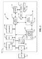
- FIG. 2is a block diagram of an illustrative embodiment of a disc drive system for selective data mirroring
- FIG. 3is a general diagram of an illustrative embodiment of a data storage surface in a disc drive
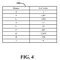
- FIG. 4is a diagram of an illustrative embodiment of a table for selective data mirroring in a disc drive.
- FIG. 5is a flow diagram of a particular illustrative embodiment of a method of selective data mirroring.
- a devicein a particular embodiment, includes a data storage medium and a controller operably coupled to the data storage medium.
- the controllerconfigured to selectively enable a data mirroring function to copy data in a first data storage location of the data storage medium to one or more second data storage locations of the data storage medium when the one or more second data storage locations do not have valid primary data stored to them.
- a methodin another particular embodiment, includes storing first information in a memory to allow identification of data storage locations of a data storage medium that do not have valid primary data stored at them. The method also includes selectively enabling a data mirroring function to copy first valid primary data from a first data storage location of the data storage medium to a second data storage location when the second data storage location does not have valid primary data stored to it. The method further includes copying the first valid primary data from the first data storage location to the second data storage location when the data mirroring function is enabled.
- a computer-readable mediumincludes instructions to cause a processor to execute a method that includes storing information in a memory to identify data storage locations of a data storage medium that have not had valid primary data written to them. The method also includes selectively enabling a data mirroring function to copy first valid primary data from a first data storage location of the data storage medium to a second data storage location when the second data storage location does not have valid primary data stored to it. The method further includes copying the first valid primary data from the first data storage location to the second data storage location when the data mirroring function is enabled.
- a disc drive 100includes a base 102 to which various components of the disc drive 100 are mounted.
- a top cover 104shown partially cut away, cooperates with the base 102 to form an internal, sealed environment for the disc drive.
- the components of the disc drive 100include a spindle motor 106 , which rotates one or more discs 108 .
- Informationis written to and read from tracks on the discs 108 through the use of an actuator assembly 110 that rotates about a bearing shaft assembly 112 positioned adjacent the discs 108 .
- the actuator assembly 110includes one or more actuator arms 114 that extend toward the discs 108 , with one or more flexures 116 extending from the actuator arms 114 .
- Mounted at the distal end of each of the flexures 116is a head 118 including an air bearing slider (not shown) that enables the head 118 to fly in close proximity above the corresponding surface of the associated disc 108 .
- the track position of the heads 118is controlled, during a seek operation, through the use of a voice coil motor (VCM) 124 that typically includes a coil 126 attached to the actuator assembly 110 , as well as one or more permanent magnets 128 that establish a magnetic field in which the coil 126 is immersed.
- VCMvoice coil motor
- the controlled application of current to the coil 126causes magnetic interaction between the permanent magnets 128 and the coil 126 so that the coil 126 moves in accordance with the well-known Lorentz relationship.
- the actuator assembly 110pivots about the bearing shaft assembly 112 , and the heads 118 are caused to move across the surfaces of the discs 108 .
- a flex assembly 130provides requisite electrical connection paths for the actuator assembly 110 while allowing pivotal movement of the actuator assembly 110 during operation.
- the flex assembly 130can include a printed circuit board 132 to which head wires (not shown) are connected. The head wires may be routed along the actuator arms 114 and the flexures 116 to the heads 118 .
- the printed circuit board 132may include circuitry for controlling the write currents applied to the heads 118 during a write operation and a preamplifier (not shown) for amplifying read signals generated by the heads 118 during a read operation.
- the flex assembly 130terminates at a flex bracket 134 for communication through the base 102 to a disc drive printed circuit board (not shown) mounted to the disc drive 100 .
- a plurality of nominally circular, concentric tracks 109are located on the surface of the discs 108 .
- Each track 109includes a number of servo fields that are interspersed with user data fields along the track 109 .
- the user data fieldsare used to store user data
- the servo fieldsare used to store servo information used by a disc drive servo system to control the position of the heads 118 .
- FIG. 2provides a functional block diagram of the disc drive 100 .
- the disc drive 100can communicate with a host device 201 (such as a personal computer) and directs overall disc drive operation.
- the disc drive 100can include a programmable controller 220 with an associated microprocessor 224 .
- the disc drive 100may also include a buffer 202 , an error correction code (ECC) block 204 , a sequencer 206 , and an input/output (I/O) control block 210 .
- ECCerror correction code
- I/Oinput/output
- the buffer 202can temporarily store user data during read and write operations, and may include a command queue (CQ) 208 where multiple pending access operations can be temporarily stored pending execution.
- the ECC block 204may apply on-the-fly error detection and correction to retrieved data.
- the sequencer 206can assert read and write gates to direct the reading and writing of data.
- the I/O control block 210serves as an interface with the host device 201 .
- FIG. 2further shows the disc drive 100 may include a read/write (R/W) channel 212 that can encode data during write operations and reconstruct user data retrieved from the discs 108 during read operations.
- R/Wread/write
- a preamplifier/driver circuit (preamp) 132can apply write currents to the heads 118 and can provide pre-amplification of readback signals.
- a servo control circuit 228may use servo data to provide the appropriate current to the coil 126 to position the heads 118 .
- the controller 220can communicate with a processor 226 to move the heads 118 to the desired locations on the disc 108 during execution of the various pending commands in the command queue 208 .
- the disc drive 100may also include a solid state non-volatile memory device 240 .
- the solid state non-volatile memory device 240may be a flash memory device.
- the flash memory devicemay be used to store a table 242 that can include information to identify data storage locations of the data storage medium that have not had valid primary data written to them.
- Valid primary dataincludes a most recent version of data stored to a storage location of a data storage medium.
- the tablemay list the data storage locations that have had valid primary data written to them or the data storage locations that have not had valid primary data written to them.
- the tablecan be updated to keep the table current when valid primary data is written to or removed from a data location.
- the controller 220may also include a data mirroring module 230 that is operable to perform a data mirroring function to copy valid primary data from a first memory location of the discs 108 to a second memory location of the discs 108 when the second memory location does not have valid primary data stored to it, based on the information stored in the table 242 .
- the controller 220may enable the data mirroring function when there are enough data storage locations that do not have valid primary data written to them to mirror substantially all valid primary data stored on the discs 108 .
- the controller 220may enable the data mirroring function when there are enough data storage locations, that do not have valid primary data written to them, to mirror a selected subset of valid primary data stored on the discs 108 , where the selected subset may be less than all of the valid primary data that is available for data mirroring.
- the selected subsetmay include valid primary data stored in a specific region of the discs 108 .
- the controller 220may store data in the specific region based on a criticality of the data. For example, data corresponding to word processing documents may be more critical than data corresponding to a video or audio file.
- the data mirroring module 230may selectively mirror data that exceeds a threshold based on a level of criticality of the data.
- the data mirroring module 230may also selectively mirror data based on a type of the data or a location of the data.
- the data mirroring module 230may selectively mirror a specific type of data, such as spreadsheet data.
- the data mirroring module 230may selectively mirror data stored in a specific file allocation table location such as a folder.
- the controller 220may receive an indication from an operating system of the host 201 that valid primary data should be mirrored when there is sufficient storage capacity.
- the indicationmay be an indicator relating to a type of the valid primary data, a level of criticality of the valid primary data, or an enable mirroring command.
- the controller 220may retrieve secondary data from a mirror location when an original memory location is not available.
- the original memory locationmay not be available due to read errors, media errors, erasure, or numerous other issues.
- the controller 220may retrieve secondary data from a mirror location when secondary data at the mirror location can be retrieved faster than valid primary data at an original memory location.
- the controller 220may retrieve secondary data from a mirror location when a read head, such as the heads 118 shown in FIG. 1 , can reach a copy of data at a mirrored location faster than the valid primary data at the original location. This may be determined based on a relative position of a read head to the mirrored location, the original location, or a number of rotations necessary to reach each location.
- FIG. 3is a diagrammatic representation of a simplified top view of a disc 300 , such as one of the discs 108 shown in FIG. 1 and FIG. 2 , having a surface 302 .
- the disc 300includes a plurality of concentric tracks 304 , 306 , 308 , 310 , 312 , and 314 for storing data on the surface 302 .
- FIG. 3only shows a relatively small number of tracks (i.e., 6) for ease of illustration, it should be appreciated that typically tens of thousands of tracks are included on the surface 302 of the disc 300 .
- Each track 304 , 306 , 308 , 310 , 312 , and 314is divided into a plurality of data sectors 320 and a plurality of servo sectors 322 .
- the servo sectors 322 in each trackcan be radially aligned with servo sectors 322 in the other tracks, thereby forming servo wedges 324 which extend radially across the disc 300 .
- a systemsuch as the disc drive 200 shown in FIG. 2 may copy data from a first particular region 326 to a second particular region 328 , such that two copies of the data exist on the disc 300 .
- the first particular region 326 and the second particular region 328may be located 180 degrees from each other on the surface 302 .
- the first particular region 326 and the second particular region 328may be located at any of the locations of data sectors 320 on the surface 302 .
- the systemmay select the second particular region so that data at the second particular region is likely to be retrieved faster than data at the first particular region.
- FIG. 4is a diagram of an illustrative embodiment of a table 400 that may be used for selective data mirroring in a data storage device.
- the table 400lists data storage locations that have had valid primary data written to them.
- the data storage locations listed in the tablemay comprise a region of data storage locations.
- the regionmay comprise one or more sectors, one or more tracks, or a surface of a disc, such as the disc 300 shown in FIG. 3 .
- the table 400may store information related to data storage locations that do not have valid primary data written to them.
- the table 400may be used to determine when to perform a selective mirroring function.
- a data storage devicemay mirror selected data.
- the method 500includes storing information in a table, such as the table 400 depicted in FIG. 4 , in memory to determine data storage locations of a data storage medium that do not have valid primary data written to them, at 502 .
- the tablemay be store in a non-volatile solid state memory, such as the flash memory 240 shown in FIG. 2 .
- valid primary datacan be user data.
- the tablemay store information related to data storage locations that have had valid primary data written to them, information related to data storage locations that do not have valid primary data written to them, information related to data storage locations that are not currently in use by the user, or information related to data storage locations that are currently in use by the user.
- the tablemay store information identifying a number of data store operations that have occurred in a specific region.
- the method 500may also include monitoring the data storage medium for data being written to or erased from the data storage locations and updating the table to identify data storage locations that do not have valid primary data written to them, at 504 .
- the tablecan be updated to keep the information in the table current. Also, the table can be updated, such as after data is stored, to indicate that a memory location has valid primary data stored to it. Further, the table can be updated, such as after data is unwritten, to indicate that a memory location does not have valid primary data stored to it.
- the method 500may also include determining when there are enough data storage locations that do not have valid primary data stored to them to mirror selected data, at 506 . When there is not enough data storage locations that do not have valid primary data stored to them to mirror the selected data, the method 500 does not enable a data mirroring function, at 508 . The method 500 may then return to the monitoring, at 504 . When there is enough data storage locations that do not have valid primary data stored to them to mirror the selected data, the method 500 enables a data mirroring function, at 510 .
- the data mirroring functionmay copy data from a first memory location of the data storage medium to a second memory location of the data storage medium when the second memory location does not have valid primary data stored to it, at 512 .
- the method 500may then return to the monitoring, at 504 .
- the method 500may be implemented in a data storage device, such as the disc drive 100 shown in FIG. 1 and FIG. 2 , to execute in real-time.
- the data storage devicemay selectively mirror data based on an available unused capacity of data storage.
- the data storage devicemay selectively mirror data from a first data storage medium to a second data storage medium.
- the first data storage medium and the second data storage mediummay be a different type of data storage medium.
- the first data storage mediummay be a magnetic disc and the second data storage medium may be a non-volatile solid state memory, such as flash memory.
- Selective data mirroringmay improve reliability by providing multiple copies of selected data, improve performance by providing multiple copies that may allow faster access times, or both.
- the data storage devicemay select a secondary data storage location for the data mirroring to increase a reliability of the data storage device. For example, the data storage device may choose a region of a data storage medium known to have a relatively high reliability to store the mirrored data. In another particular embodiment, the data storage device may choose another data storage medium of a different type to store the mirrored data, such as a non-volatile solid state memory.
- the data storage devicemay also select a secondary data storage location for the data mirroring such that the mirrored data is likely to be retrieved when the original data storage location is not available.
- the data storage devicemay select a secondary data storage location for the data mirroring based on when data at the secondary data storage location can be retrieved faster than at the original data storage location.
- the data storage devicemay select a secondary data storage location for the data mirroring based on when data at the secondary data storage location can be retrieved using less energy than data at the original data storage location.
- the data storage devicemay select a secondary data storage location for the data mirroring based on when data at the secondary data storage location can be retrieved more quietly than data at the original data storage location.
- a data storage devicesuch as the disc drive 100 shown in FIG. 1 and FIG. 2 , may selectively retrieve data from a second data storage location that stores mirrored data when data at the second data storage location can be retrieved faster than the primary data at the original data storage location.
- a controller of the data storage devicemay implement an algorithm to determine a first access time to an original data storage location and a second access time to a second data storage location that contains data mirrored from the original data storage location. The controller may then select to retrieve the primary data from the original data storage location or the mirrored data from the second data storage location based on which location has a faster access time. The controller may selectively implement this feature based on user input, a setting of the data storage device, a setting of a system incorporating the data storage device, or any combination thereof.
- a data storage devicesuch as the disc drive 100 shown in FIG. 1 and FIG. 2 , may selectively retrieve data from a second data storage location that stores mirrored data when data at the second data storage location can be retrieved using less energy than data at the original data storage location.
- a controller of the data storage devicemay implement an algorithm to determine a first energy estimate to access an original data storage location and a second energy estimate to access a second data storage location that contains data mirrored from the original data storage location. The controller may then select to retrieve the primary data from the original data storage location or the mirrored data from the second data storage location based on which location can be accessed using less energy.
- the disc drivemay choose to retrieve data from a second data storage location that contains mirrored data when the second data storage location can be accessed by expending less energy than may be needed to increase the rotational speed of the spindle motor. This may occur when the second data storage location that stores the mirrored data is a non-volatile solid state memory, such as a flash memory.
- the controllermay selectively implement this feature based on user input, a setting of the data storage device, a setting of a system incorporating the data storage device, or any combination thereof.
- a data storage devicesuch as the disc drive 100 shown in FIG. 1 and FIG. 2 , may selectively retrieve data from a second data storage location that stores mirrored data when data at the second data storage location can be retrieved more quietly than data at the original data storage location.
- a controller of the data storage devicemay implement an algorithm to determine a first noise measurement estimate to access an original data storage location and a second noise estimate to access a second data storage location that contains data mirrored from the original data storage location. The controller may then select to retrieve the primary data from the original data storage location or the mirrored data from the second data storage location based on which location can be accessed while causing the least amount of noise.
- the disc drivemay choose to retrieve data from a second data storage location that contains mirrored data when the second data storage location can be accessed by creating less noise than may be needed to increase the rotational speed of the spindle motor. This may occur when the second data storage location that stores the mirrored data is a non-volatile solid state memory, such as a flash memory.
- the controllermay selectively implement this feature based on user input, a setting of the data storage device, a setting of a system incorporating the data storage device, or any combination thereof.
- the data storage devicemay selectively disable data mirroring when a larger capacity of data storage for valid primary data is needed.
- the data storage devicemay make the locations used for the data mirroring available for storing other valid primary data.
- the data storage devicemay make previous mirror locations available by returning the secondary data storage locations to a state that does not have associated data and does not hold valid primary data. This may be done by erasing or deallocating the locations previously used for data mirroring.
- a usermay enable a selective data mirroring function.
- a data storage devicemay determine when to implement a selective data mirroring function without input from a user. For example, the data storage device may selectively enable a data mirroring function when a sufficient capacity exists to mirror selected data.
- a controllercan selectively enable and disable a data mirroring function based on information in a table and without receiving direction from a source external to the device controller by the controller.
- the methods described hereinmay be implemented as one or more software programs running on a computer processor or controller, such as the controller 220 .
- the methods described hereinmay be implemented as one or more software programs running on a host device, such as a PC that is using a disc drive.
- a host devicesuch as a PC that is using a disc drive.
- Dedicated hardware implementationsincluding, but not limited to, application specific integrated circuits, programmable logic arrays and other hardware devices can likewise be constructed to implement the methods described herein.
- inventions of the disclosuremay be referred to herein, individually and/or collectively, by the term “invention” merely for convenience and without intending to limit the scope of this application to any particular invention or inventive concept.
- inventionsmerely for convenience and without intending to limit the scope of this application to any particular invention or inventive concept.
- specific embodimentshave been illustrated and described herein, it should be appreciated that any subsequent arrangement designed to achieve the same or similar purpose may be substituted for the specific embodiments shown.
- This disclosureis intended to cover any and all subsequent adaptations or variations of various embodiments. Combinations of the above embodiments, and other embodiments not specifically described herein, will be apparent to those of skill in the art upon reviewing the description.
Landscapes
- Engineering & Computer Science (AREA)
- Theoretical Computer Science (AREA)
- Quality & Reliability (AREA)
- Physics & Mathematics (AREA)
- General Engineering & Computer Science (AREA)
- General Physics & Mathematics (AREA)
- Signal Processing For Digital Recording And Reproducing (AREA)
Abstract
Description
Claims (24)
Priority Applications (1)
| Application Number | Priority Date | Filing Date | Title |
|---|---|---|---|
| US11/961,823US8028137B2 (en) | 2007-12-20 | 2007-12-20 | System and method of selective data mirroring in a data storage device |
Applications Claiming Priority (1)
| Application Number | Priority Date | Filing Date | Title |
|---|---|---|---|
| US11/961,823US8028137B2 (en) | 2007-12-20 | 2007-12-20 | System and method of selective data mirroring in a data storage device |
Publications (2)
| Publication Number | Publication Date |
|---|---|
| US20090164742A1 US20090164742A1 (en) | 2009-06-25 |
| US8028137B2true US8028137B2 (en) | 2011-09-27 |
Family
ID=40790045
Family Applications (1)
| Application Number | Title | Priority Date | Filing Date |
|---|---|---|---|
| US11/961,823Expired - Fee RelatedUS8028137B2 (en) | 2007-12-20 | 2007-12-20 | System and method of selective data mirroring in a data storage device |
Country Status (1)
| Country | Link |
|---|---|
| US (1) | US8028137B2 (en) |
Cited By (2)
| Publication number | Priority date | Publication date | Assignee | Title |
|---|---|---|---|---|
| US20160217031A1 (en)* | 2015-01-27 | 2016-07-28 | Quantum Corporation | Efficient High/Low Energy Zone Solid State Device Data Storage |
| US9984000B2 (en) | 2013-09-06 | 2018-05-29 | Lyve Minds, Inc. | Electronic device data distribution |
Families Citing this family (13)
| Publication number | Priority date | Publication date | Assignee | Title |
|---|---|---|---|---|
| US8090977B2 (en)* | 2009-12-21 | 2012-01-03 | Intel Corporation | Performing redundant memory hopping |
| US8407516B2 (en)* | 2009-12-23 | 2013-03-26 | Intel Corporation | Controlling memory redundancy in a system |
| US8521972B1 (en) | 2010-06-30 | 2013-08-27 | Western Digital Technologies, Inc. | System and method for optimizing garbage collection in data storage |
| US8990538B2 (en)* | 2010-11-05 | 2015-03-24 | Microsoft Corporation | Managing memory with limited write cycles in heterogeneous memory systems |
| US8627176B2 (en) | 2010-11-30 | 2014-01-07 | Microsoft Corporation | Systematic mitigation of memory errors |
| US9189392B1 (en) | 2011-06-30 | 2015-11-17 | Western Digital Technologies, Inc. | Opportunistic defragmentation during garbage collection |
| US8819375B1 (en) | 2011-11-30 | 2014-08-26 | Western Digital Technologies, Inc. | Method for selective defragmentation in a data storage device |
| CN102546782B (en)* | 2011-12-28 | 2015-04-29 | 北京奇虎科技有限公司 | A distributed system and its data operation method |
| US8788778B1 (en) | 2012-06-04 | 2014-07-22 | Western Digital Technologies, Inc. | Garbage collection based on the inactivity level of stored data |
| US8914668B2 (en)* | 2012-09-06 | 2014-12-16 | International Business Machines Corporation | Asynchronous raid stripe writes to enable response to media errors |
| US8843779B1 (en)* | 2012-09-12 | 2014-09-23 | Western Digital Technologies, Inc. | Disk drive backup protection using a signature with an enhanced file manager |
| US9032172B2 (en)* | 2013-02-11 | 2015-05-12 | International Business Machines Corporation | Systems, methods and computer program products for selective copying of track data through peer-to-peer remote copy |
| US11520789B2 (en)* | 2019-10-21 | 2022-12-06 | Teradata Us, Inc. | Caching objects from a data store |
Citations (19)
| Publication number | Priority date | Publication date | Assignee | Title |
|---|---|---|---|---|
| US5185662A (en) | 1991-01-28 | 1993-02-09 | Eastman Kodak Company | Method and apparatus for producing copy with selective area treatment |
| US5572660A (en) | 1993-10-27 | 1996-11-05 | Dell Usa, L.P. | System and method for selective write-back caching within a disk array subsystem |
| US5615352A (en) | 1994-10-05 | 1997-03-25 | Hewlett-Packard Company | Methods for adding storage disks to a hierarchic disk array while maintaining data availability |
| US5742792A (en) | 1993-04-23 | 1998-04-21 | Emc Corporation | Remote data mirroring |
| US5819310A (en) | 1996-05-24 | 1998-10-06 | Emc Corporation | Method and apparatus for reading data from mirrored logical volumes on physical disk drives |
| US5835953A (en) | 1994-10-13 | 1998-11-10 | Vinca Corporation | Backup system that takes a snapshot of the locations in a mass storage device that has been identified for updating prior to updating |
| US6023584A (en) | 1997-01-03 | 2000-02-08 | Ncr Corporation | Installation of computer programs using disk mirroring |
| US6237008B1 (en) | 1998-07-20 | 2001-05-22 | International Business Machines Corporation | System and method for enabling pair-pair remote copy storage volumes to mirror data in another storage volume |
| US6910098B2 (en) | 2001-10-16 | 2005-06-21 | Emc Corporation | Method and apparatus for maintaining data coherency |
| US6931499B2 (en) | 2002-08-01 | 2005-08-16 | Lsi Logic Corporation | Method and apparatus for copying data between storage volumes of storage systems |
| US20060020754A1 (en)* | 2004-07-21 | 2006-01-26 | Susumu Suzuki | Storage system |
| US7099903B2 (en)* | 2004-04-22 | 2006-08-29 | Hitachi, Ltd. | Method and system for data processing with data backup |
| US7107320B2 (en) | 2001-11-02 | 2006-09-12 | Dot Hill Systems Corp. | Data mirroring between controllers in an active-active controller pair |
| US7152182B2 (en) | 2003-06-06 | 2006-12-19 | Hewlett-Packard Development Company, L.P. | Data redundancy system and method |
| US7165141B2 (en) | 2004-02-27 | 2007-01-16 | Hewlett-Packard Development Company, L.P. | Daisy-chained device-mirroring architecture |
| US7254683B2 (en) | 2003-11-03 | 2007-08-07 | International Business Machines Corporation | Speculative data mirroring apparatus method and system |
| US7254686B2 (en) | 2005-03-31 | 2007-08-07 | International Business Machines Corporation | Switching between mirrored and non-mirrored volumes |
| US7278049B2 (en) | 2003-09-29 | 2007-10-02 | International Business Machines Corporation | Method, system, and program for recovery from a failure in an asynchronous data copying system |
| US7421552B2 (en)* | 2006-03-17 | 2008-09-02 | Emc Corporation | Techniques for managing data within a data storage system utilizing a flash-based memory vault |
- 2007
- 2007-12-20USUS11/961,823patent/US8028137B2/ennot_activeExpired - Fee Related
Patent Citations (19)
| Publication number | Priority date | Publication date | Assignee | Title |
|---|---|---|---|---|
| US5185662A (en) | 1991-01-28 | 1993-02-09 | Eastman Kodak Company | Method and apparatus for producing copy with selective area treatment |
| US5742792A (en) | 1993-04-23 | 1998-04-21 | Emc Corporation | Remote data mirroring |
| US5572660A (en) | 1993-10-27 | 1996-11-05 | Dell Usa, L.P. | System and method for selective write-back caching within a disk array subsystem |
| US5615352A (en) | 1994-10-05 | 1997-03-25 | Hewlett-Packard Company | Methods for adding storage disks to a hierarchic disk array while maintaining data availability |
| US5835953A (en) | 1994-10-13 | 1998-11-10 | Vinca Corporation | Backup system that takes a snapshot of the locations in a mass storage device that has been identified for updating prior to updating |
| US5819310A (en) | 1996-05-24 | 1998-10-06 | Emc Corporation | Method and apparatus for reading data from mirrored logical volumes on physical disk drives |
| US6023584A (en) | 1997-01-03 | 2000-02-08 | Ncr Corporation | Installation of computer programs using disk mirroring |
| US6237008B1 (en) | 1998-07-20 | 2001-05-22 | International Business Machines Corporation | System and method for enabling pair-pair remote copy storage volumes to mirror data in another storage volume |
| US6910098B2 (en) | 2001-10-16 | 2005-06-21 | Emc Corporation | Method and apparatus for maintaining data coherency |
| US7107320B2 (en) | 2001-11-02 | 2006-09-12 | Dot Hill Systems Corp. | Data mirroring between controllers in an active-active controller pair |
| US6931499B2 (en) | 2002-08-01 | 2005-08-16 | Lsi Logic Corporation | Method and apparatus for copying data between storage volumes of storage systems |
| US7152182B2 (en) | 2003-06-06 | 2006-12-19 | Hewlett-Packard Development Company, L.P. | Data redundancy system and method |
| US7278049B2 (en) | 2003-09-29 | 2007-10-02 | International Business Machines Corporation | Method, system, and program for recovery from a failure in an asynchronous data copying system |
| US7254683B2 (en) | 2003-11-03 | 2007-08-07 | International Business Machines Corporation | Speculative data mirroring apparatus method and system |
| US7165141B2 (en) | 2004-02-27 | 2007-01-16 | Hewlett-Packard Development Company, L.P. | Daisy-chained device-mirroring architecture |
| US7099903B2 (en)* | 2004-04-22 | 2006-08-29 | Hitachi, Ltd. | Method and system for data processing with data backup |
| US20060020754A1 (en)* | 2004-07-21 | 2006-01-26 | Susumu Suzuki | Storage system |
| US7254686B2 (en) | 2005-03-31 | 2007-08-07 | International Business Machines Corporation | Switching between mirrored and non-mirrored volumes |
| US7421552B2 (en)* | 2006-03-17 | 2008-09-02 | Emc Corporation | Techniques for managing data within a data storage system utilizing a flash-based memory vault |
Cited By (3)
| Publication number | Priority date | Publication date | Assignee | Title |
|---|---|---|---|---|
| US9984000B2 (en) | 2013-09-06 | 2018-05-29 | Lyve Minds, Inc. | Electronic device data distribution |
| US20160217031A1 (en)* | 2015-01-27 | 2016-07-28 | Quantum Corporation | Efficient High/Low Energy Zone Solid State Device Data Storage |
| US9846613B2 (en)* | 2015-01-27 | 2017-12-19 | Quantum Corporation | Efficient high/low energy zone solid state device data storage |
Also Published As
| Publication number | Publication date |
|---|---|
| US20090164742A1 (en) | 2009-06-25 |
Similar Documents
| Publication | Publication Date | Title |
|---|---|---|
| US8028137B2 (en) | System and method of selective data mirroring in a data storage device | |
| US8179627B2 (en) | Floating guard band for shingle magnetic recording | |
| US8937782B1 (en) | Hard disk drive assembly including a NVSM to store configuration data for controlling disk drive operations | |
| US8819375B1 (en) | Method for selective defragmentation in a data storage device | |
| US8755141B1 (en) | Hard disk drive assembly including a NVSM located within a preamplifier to store configuration data for controlling disk drive operations | |
| US7606970B2 (en) | Hybrid disk drive and method of controlling data therein | |
| US8122322B2 (en) | System and method of storing reliability data | |
| US7567400B2 (en) | Method and apparatus for improving the error rate of track information on a magnetic storage device | |
| US20070162693A1 (en) | Hybrid hard disk drive control method and recording medium and apparatus suitable therefor | |
| US10614852B2 (en) | Data-center drive with split-actuator that increases read/write performance via data striping | |
| US8131920B2 (en) | Method and system for dynamically allocating read and write sequence randomizer | |
| US20100030987A1 (en) | Data storing location managing method and data storage system | |
| US8291190B2 (en) | Disk drive including a host interface supporting different sizes of data sectors and method for writing data thereto | |
| US7042664B2 (en) | Method and system for host programmable data storage device self-testing | |
| CN111696586A (en) | Magnetic disk apparatus and control method thereof | |
| CN101226505A (en) | Magnetic disk device and method of controlling the same | |
| US8832366B1 (en) | Disk drive to coalesce unaligned writes in write operations | |
| US8014245B2 (en) | System and method of defect description of a data storage medium | |
| CN115116479B (en) | Magnetic disk device | |
| US10318173B2 (en) | Multi-speed data storage device with media cache for high speed writes | |
| JP2005267497A (en) | Data storage device, control method thereof, and magnetic disk storage device | |
| US20110283044A1 (en) | Device and method for reliable data storage | |
| US8032699B2 (en) | System and method of monitoring data storage activity | |
| US7184241B1 (en) | Disk drive that performs cold writes to erased buffer | |
| US20080266697A1 (en) | Information recording device, recording device management system and information recording device management method |
Legal Events
| Date | Code | Title | Description |
|---|---|---|---|
| AS | Assignment | Owner name:SEAGATE TECHNOLOGY LLC,CALIFORNIA Free format text:ASSIGNMENT OF ASSIGNORS INTEREST;ASSIGNORS:WACH, JOSEPH L;FELDMAN, TIMOTHY RICHARD;REEL/FRAME:020280/0477 Effective date:20071220 Owner name:SEAGATE TECHNOLOGY LLC, CALIFORNIA Free format text:ASSIGNMENT OF ASSIGNORS INTEREST;ASSIGNORS:WACH, JOSEPH L;FELDMAN, TIMOTHY RICHARD;REEL/FRAME:020280/0477 Effective date:20071220 | |
| AS | Assignment | Owner name:WELLS FARGO BANK, NATIONAL ASSOCIATION, AS COLLATERAL AGENT AND SECOND PRIORITY REPRESENTATIVE, CALIFORNIA Free format text:SECURITY AGREEMENT;ASSIGNORS:MAXTOR CORPORATION;SEAGATE TECHNOLOGY LLC;SEAGATE TECHNOLOGY INTERNATIONAL;REEL/FRAME:022757/0017 Effective date:20090507 Owner name:JPMORGAN CHASE BANK, N.A., AS ADMINISTRATIVE AGENT AND FIRST PRIORITY REPRESENTATIVE, NEW YORK Free format text:SECURITY AGREEMENT;ASSIGNORS:MAXTOR CORPORATION;SEAGATE TECHNOLOGY LLC;SEAGATE TECHNOLOGY INTERNATIONAL;REEL/FRAME:022757/0017 Effective date:20090507 Owner name:JPMORGAN CHASE BANK, N.A., AS ADMINISTRATIVE AGENT Free format text:SECURITY AGREEMENT;ASSIGNORS:MAXTOR CORPORATION;SEAGATE TECHNOLOGY LLC;SEAGATE TECHNOLOGY INTERNATIONAL;REEL/FRAME:022757/0017 Effective date:20090507 Owner name:WELLS FARGO BANK, NATIONAL ASSOCIATION, AS COLLATE Free format text:SECURITY AGREEMENT;ASSIGNORS:MAXTOR CORPORATION;SEAGATE TECHNOLOGY LLC;SEAGATE TECHNOLOGY INTERNATIONAL;REEL/FRAME:022757/0017 Effective date:20090507 | |
| AS | Assignment | Owner name:SEAGATE TECHNOLOGY HDD HOLDINGS, CALIFORNIA Free format text:RELEASE;ASSIGNOR:JPMORGAN CHASE BANK, N.A., AS ADMINISTRATIVE AGENT;REEL/FRAME:025662/0001 Effective date:20110114 Owner name:SEAGATE TECHNOLOGY LLC, CALIFORNIA Free format text:RELEASE;ASSIGNOR:JPMORGAN CHASE BANK, N.A., AS ADMINISTRATIVE AGENT;REEL/FRAME:025662/0001 Effective date:20110114 Owner name:MAXTOR CORPORATION, CALIFORNIA Free format text:RELEASE;ASSIGNOR:JPMORGAN CHASE BANK, N.A., AS ADMINISTRATIVE AGENT;REEL/FRAME:025662/0001 Effective date:20110114 Owner name:SEAGATE TECHNOLOGY INTERNATIONAL, CALIFORNIA Free format text:RELEASE;ASSIGNOR:JPMORGAN CHASE BANK, N.A., AS ADMINISTRATIVE AGENT;REEL/FRAME:025662/0001 Effective date:20110114 | |
| AS | Assignment | Owner name:THE BANK OF NOVA SCOTIA, AS ADMINISTRATIVE AGENT, CANADA Free format text:SECURITY AGREEMENT;ASSIGNOR:SEAGATE TECHNOLOGY LLC;REEL/FRAME:026010/0350 Effective date:20110118 Owner name:THE BANK OF NOVA SCOTIA, AS ADMINISTRATIVE AGENT, Free format text:SECURITY AGREEMENT;ASSIGNOR:SEAGATE TECHNOLOGY LLC;REEL/FRAME:026010/0350 Effective date:20110118 | |
| ZAAA | Notice of allowance and fees due | Free format text:ORIGINAL CODE: NOA | |
| ZAAB | Notice of allowance mailed | Free format text:ORIGINAL CODE: MN/=. | |
| STCF | Information on status: patent grant | Free format text:PATENTED CASE | |
| AS | Assignment | Owner name:EVAULT INC. (F/K/A I365 INC.), CALIFORNIA Free format text:TERMINATION AND RELEASE OF SECURITY INTEREST IN PATENT RIGHTS;ASSIGNOR:WELLS FARGO BANK, NATIONAL ASSOCIATION, AS COLLATERAL AGENT AND SECOND PRIORITY REPRESENTATIVE;REEL/FRAME:030833/0001 Effective date:20130312 Owner name:SEAGATE TECHNOLOGY US HOLDINGS, INC., CALIFORNIA Free format text:TERMINATION AND RELEASE OF SECURITY INTEREST IN PATENT RIGHTS;ASSIGNOR:WELLS FARGO BANK, NATIONAL ASSOCIATION, AS COLLATERAL AGENT AND SECOND PRIORITY REPRESENTATIVE;REEL/FRAME:030833/0001 Effective date:20130312 Owner name:SEAGATE TECHNOLOGY INTERNATIONAL, CAYMAN ISLANDS Free format text:TERMINATION AND RELEASE OF SECURITY INTEREST IN PATENT RIGHTS;ASSIGNOR:WELLS FARGO BANK, NATIONAL ASSOCIATION, AS COLLATERAL AGENT AND SECOND PRIORITY REPRESENTATIVE;REEL/FRAME:030833/0001 Effective date:20130312 Owner name:SEAGATE TECHNOLOGY LLC, CALIFORNIA Free format text:TERMINATION AND RELEASE OF SECURITY INTEREST IN PATENT RIGHTS;ASSIGNOR:WELLS FARGO BANK, NATIONAL ASSOCIATION, AS COLLATERAL AGENT AND SECOND PRIORITY REPRESENTATIVE;REEL/FRAME:030833/0001 Effective date:20130312 | |
| FPAY | Fee payment | Year of fee payment:4 | |
| MAFP | Maintenance fee payment | Free format text:PAYMENT OF MAINTENANCE FEE, 8TH YEAR, LARGE ENTITY (ORIGINAL EVENT CODE: M1552); ENTITY STATUS OF PATENT OWNER: LARGE ENTITY Year of fee payment:8 | |
| FEPP | Fee payment procedure | Free format text:MAINTENANCE FEE REMINDER MAILED (ORIGINAL EVENT CODE: REM.); ENTITY STATUS OF PATENT OWNER: LARGE ENTITY | |
| LAPS | Lapse for failure to pay maintenance fees | Free format text:PATENT EXPIRED FOR FAILURE TO PAY MAINTENANCE FEES (ORIGINAL EVENT CODE: EXP.); ENTITY STATUS OF PATENT OWNER: LARGE ENTITY | |
| STCH | Information on status: patent discontinuation | Free format text:PATENT EXPIRED DUE TO NONPAYMENT OF MAINTENANCE FEES UNDER 37 CFR 1.362 | |
| FP | Lapsed due to failure to pay maintenance fee | Effective date:20230927 | |
| AS | Assignment | Owner name:SEAGATE TECHNOLOGY PUBLIC LIMITED COMPANY, CALIFORNIA Free format text:RELEASE BY SECURED PARTY;ASSIGNOR:THE BANK OF NOVA SCOTIA;REEL/FRAME:072193/0001 Effective date:20250303 Owner name:SEAGATE TECHNOLOGY, CALIFORNIA Free format text:RELEASE BY SECURED PARTY;ASSIGNOR:THE BANK OF NOVA SCOTIA;REEL/FRAME:072193/0001 Effective date:20250303 Owner name:SEAGATE TECHNOLOGY HDD HOLDINGS, CALIFORNIA Free format text:RELEASE BY SECURED PARTY;ASSIGNOR:THE BANK OF NOVA SCOTIA;REEL/FRAME:072193/0001 Effective date:20250303 Owner name:I365 INC., CALIFORNIA Free format text:RELEASE BY SECURED PARTY;ASSIGNOR:THE BANK OF NOVA SCOTIA;REEL/FRAME:072193/0001 Effective date:20250303 Owner name:SEAGATE TECHNOLOGY LLC, CALIFORNIA Free format text:RELEASE BY SECURED PARTY;ASSIGNOR:THE BANK OF NOVA SCOTIA;REEL/FRAME:072193/0001 Effective date:20250303 Owner name:SEAGATE TECHNOLOGY INTERNATIONAL, CAYMAN ISLANDS Free format text:RELEASE BY SECURED PARTY;ASSIGNOR:THE BANK OF NOVA SCOTIA;REEL/FRAME:072193/0001 Effective date:20250303 Owner name:SEAGATE HDD CAYMAN, CAYMAN ISLANDS Free format text:RELEASE BY SECURED PARTY;ASSIGNOR:THE BANK OF NOVA SCOTIA;REEL/FRAME:072193/0001 Effective date:20250303 Owner name:SEAGATE TECHNOLOGY (US) HOLDINGS, INC., CALIFORNIA Free format text:RELEASE BY SECURED PARTY;ASSIGNOR:THE BANK OF NOVA SCOTIA;REEL/FRAME:072193/0001 Effective date:20250303 |