US8027771B2 - Method and apparatus to monitor an output speed sensor during operation of an electro-mechanical transmission - Google Patents
Method and apparatus to monitor an output speed sensor during operation of an electro-mechanical transmissionDownload PDFInfo
- Publication number
- US8027771B2 US8027771B2US11/854,564US85456407AUS8027771B2US 8027771 B2US8027771 B2US 8027771B2US 85456407 AUS85456407 AUS 85456407AUS 8027771 B2US8027771 B2US 8027771B2
- Authority
- US
- United States
- Prior art keywords
- transmission
- output
- rotational speed
- expected
- electro
- Prior art date
- Legal status (The legal status is an assumption and is not a legal conclusion. Google has not performed a legal analysis and makes no representation as to the accuracy of the status listed.)
- Expired - Fee Related, expires
Links
- 230000005540biological transmissionEffects0.000titleclaimsabstractdescription143
- 238000000034methodMethods0.000titleclaimsabstractdescription19
- 238000012544monitoring processMethods0.000claimsabstractdescription13
- 238000002485combustion reactionMethods0.000claimsdescription10
- 238000012935AveragingMethods0.000claims1
- 238000012546transferMethods0.000description9
- 239000000446fuelSubstances0.000description6
- 238000005259measurementMethods0.000description6
- 238000005457optimizationMethods0.000description6
- 238000004146energy storageMethods0.000description5
- 230000006870functionEffects0.000description5
- 239000004020conductorSubstances0.000description3
- 238000001514detection methodMethods0.000description3
- 238000010586diagramMethods0.000description3
- 238000012986modificationMethods0.000description3
- 230000004048modificationEffects0.000description3
- 230000004044responseEffects0.000description3
- 230000001133accelerationEffects0.000description2
- 230000004075alterationEffects0.000description2
- 238000004891communicationMethods0.000description2
- 230000001276controlling effectEffects0.000description2
- 230000009849deactivationEffects0.000description2
- 238000012545processingMethods0.000description2
- 230000008929regenerationEffects0.000description2
- 238000011069regeneration methodMethods0.000description2
- 230000005355Hall effectEffects0.000description1
- 230000009471actionEffects0.000description1
- 239000012080ambient airSubstances0.000description1
- 230000000712assemblyEffects0.000description1
- 238000000429assemblyMethods0.000description1
- 230000008859changeEffects0.000description1
- 238000006243chemical reactionMethods0.000description1
- 230000000295complement effectEffects0.000description1
- 230000003750conditioning effectEffects0.000description1
- 239000002826coolantSubstances0.000description1
- 230000001419dependent effectEffects0.000description1
- 230000000694effectsEffects0.000description1
- 239000012530fluidSubstances0.000description1
- 230000007246mechanismEffects0.000description1
- 238000012806monitoring deviceMethods0.000description1
- 230000009467reductionEffects0.000description1
- 230000001105regulatory effectEffects0.000description1
- 230000007704transitionEffects0.000description1
- 238000004804windingMethods0.000description1
Images


Classifications
- F—MECHANICAL ENGINEERING; LIGHTING; HEATING; WEAPONS; BLASTING
- F16—ENGINEERING ELEMENTS AND UNITS; GENERAL MEASURES FOR PRODUCING AND MAINTAINING EFFECTIVE FUNCTIONING OF MACHINES OR INSTALLATIONS; THERMAL INSULATION IN GENERAL
- F16H—GEARING
- F16H61/00—Control functions within control units of change-speed- or reversing-gearings for conveying rotary motion ; Control of exclusively fluid gearing, friction gearing, gearings with endless flexible members or other particular types of gearing
- F16H61/12—Detecting malfunction or potential malfunction, e.g. fail safe ; Circumventing or fixing failures
- F—MECHANICAL ENGINEERING; LIGHTING; HEATING; WEAPONS; BLASTING
- F16—ENGINEERING ELEMENTS AND UNITS; GENERAL MEASURES FOR PRODUCING AND MAINTAINING EFFECTIVE FUNCTIONING OF MACHINES OR INSTALLATIONS; THERMAL INSULATION IN GENERAL
- F16H—GEARING
- F16H37/00—Combinations of mechanical gearings, not provided for in groups F16H1/00 - F16H35/00
- F16H37/02—Combinations of mechanical gearings, not provided for in groups F16H1/00 - F16H35/00 comprising essentially only toothed or friction gearings
- F16H37/06—Combinations of mechanical gearings, not provided for in groups F16H1/00 - F16H35/00 comprising essentially only toothed or friction gearings with a plurality of driving or driven shafts; with arrangements for dividing torque between two or more intermediate shafts
- F16H37/08—Combinations of mechanical gearings, not provided for in groups F16H1/00 - F16H35/00 comprising essentially only toothed or friction gearings with a plurality of driving or driven shafts; with arrangements for dividing torque between two or more intermediate shafts with differential gearing
- F16H37/10—Combinations of mechanical gearings, not provided for in groups F16H1/00 - F16H35/00 comprising essentially only toothed or friction gearings with a plurality of driving or driven shafts; with arrangements for dividing torque between two or more intermediate shafts with differential gearing at both ends of intermediate shafts
- F16H2037/105—Combinations of mechanical gearings, not provided for in groups F16H1/00 - F16H35/00 comprising essentially only toothed or friction gearings with a plurality of driving or driven shafts; with arrangements for dividing torque between two or more intermediate shafts with differential gearing at both ends of intermediate shafts characterised by number of modes or ranges, e.g. for compound gearing
- F16H2037/106—Combinations of mechanical gearings, not provided for in groups F16H1/00 - F16H35/00 comprising essentially only toothed or friction gearings with a plurality of driving or driven shafts; with arrangements for dividing torque between two or more intermediate shafts with differential gearing at both ends of intermediate shafts characterised by number of modes or ranges, e.g. for compound gearing with switching means to provide two variator modes or ranges
- F—MECHANICAL ENGINEERING; LIGHTING; HEATING; WEAPONS; BLASTING
- F16—ENGINEERING ELEMENTS AND UNITS; GENERAL MEASURES FOR PRODUCING AND MAINTAINING EFFECTIVE FUNCTIONING OF MACHINES OR INSTALLATIONS; THERMAL INSULATION IN GENERAL
- F16H—GEARING
- F16H3/00—Toothed gearings for conveying rotary motion with variable gear ratio or for reversing rotary motion
- F16H3/44—Toothed gearings for conveying rotary motion with variable gear ratio or for reversing rotary motion using gears having orbital motion
- F16H3/72—Toothed gearings for conveying rotary motion with variable gear ratio or for reversing rotary motion using gears having orbital motion with a secondary drive, e.g. regulating motor, in order to vary speed continuously
- F16H3/727—Toothed gearings for conveying rotary motion with variable gear ratio or for reversing rotary motion using gears having orbital motion with a secondary drive, e.g. regulating motor, in order to vary speed continuously with at least two dynamo electric machines for creating an electric power path inside the gearing, e.g. using generator and motor for a variable power torque path
- F—MECHANICAL ENGINEERING; LIGHTING; HEATING; WEAPONS; BLASTING
- F16—ENGINEERING ELEMENTS AND UNITS; GENERAL MEASURES FOR PRODUCING AND MAINTAINING EFFECTIVE FUNCTIONING OF MACHINES OR INSTALLATIONS; THERMAL INSULATION IN GENERAL
- F16H—GEARING
- F16H59/00—Control inputs to control units of change-speed- or reversing-gearings for conveying rotary motion
- F16H59/36—Inputs being a function of speed
- F16H59/44—Inputs being a function of speed dependent on machine speed, e.g. the vehicle speed
- F—MECHANICAL ENGINEERING; LIGHTING; HEATING; WEAPONS; BLASTING
- F16—ENGINEERING ELEMENTS AND UNITS; GENERAL MEASURES FOR PRODUCING AND MAINTAINING EFFECTIVE FUNCTIONING OF MACHINES OR INSTALLATIONS; THERMAL INSULATION IN GENERAL
- F16H—GEARING
- F16H59/00—Control inputs to control units of change-speed- or reversing-gearings for conveying rotary motion
- F16H59/36—Inputs being a function of speed
- F16H59/46—Inputs being a function of speed dependent on a comparison between speeds
- F—MECHANICAL ENGINEERING; LIGHTING; HEATING; WEAPONS; BLASTING
- F16—ENGINEERING ELEMENTS AND UNITS; GENERAL MEASURES FOR PRODUCING AND MAINTAINING EFFECTIVE FUNCTIONING OF MACHINES OR INSTALLATIONS; THERMAL INSULATION IN GENERAL
- F16H—GEARING
- F16H59/00—Control inputs to control units of change-speed- or reversing-gearings for conveying rotary motion
- F16H59/68—Inputs being a function of gearing status
- F16H59/70—Inputs being a function of gearing status dependent on the ratio established
Definitions
- This disclosurepertains generally to control systems for electro-mechanical transmissions.
- Powertrain architecturescomprise torque-generative devices, including internal combustion engines and electric machines, which transmit torque through a transmission device to a vehicle driveline.
- One such transmissionincludes a two-mode, compound-split, electro-mechanical transmission which utilizes an input member for receiving motive torque from a prime mover power source, typically an internal combustion engine, and an output member for delivering motive torque from the transmission to the vehicle driveline and to wheels of the vehicle.
- Electric machinesoperatively connected to an electrical energy storage device, comprise motor/generators operable to generate motive torque for input to the transmission, independently of torque input from the internal combustion engine. The electric machines are further operable to transform vehicle kinetic energy, transmitted through the vehicle driveline, to electrical energy that is storable in the electrical energy storage device.
- a control systemmonitors various inputs from the vehicle and the operator and provides operational control of the powertrain system, including controlling transmission gear shifting, controlling the torque-generative devices, and regulating the electrical power interchange between the electrical energy storage device and the electric machines.
- the exemplary electro-mechanical transmissionsare selectively operative in fixed gear operation and continuously variable operation through actuation of torque-transfer clutches, typically employing a hydraulic circuit to effect clutch actuation.
- a fixed gear operationoccurs when the ratio of the rotational speed of the transmission output member to the rotational speed of the input member is constant, typically due to actuation of one or more torque-transfer clutches.
- a continuously variable operationoccurs when the ratio of the rotational speed of the transmission output member to the rotational speed of the input member is variable based upon operating speeds of one or more electric machines.
- the electric machinescan be selectively connected to the output member via actuation of a clutch, or directly by fixed mechanical connections.
- Clutch actuation and deactivationis typically effected through a hydraulic circuit, including electrically-actuated hydraulic flow management valves, pressure control solenoids, and pressure monitoring devices controlled by a control module.
- One sensing systemcomprises a vehicle speed sensing system, comprising a sensing system adapted to monitor rotational speed of an output shaft of the transmission.
- Fault detection in the output shaft rotational speed sensing systemtypically includes monitoring signal output and detecting presence of an output signal when one is expected, e.g., wherein the engine is running and the transmission is in gear there is an expectation of an output from the sensing system.
- Fault detectionfurther includes monitoring signal output during ongoing operation and to identify an unexpected change in signal output, e.g., a drop in output by a calibrated speed (e.g., 1000 RPM) when the vehicle is operating above a specified vehicle speed (e.g.
- An electro-mechanical transmissionincludes an output.
- a method to monitor a sensing system adapted to monitor the outputincludes monitoring rotational speed of a wheel operatively connected to a driveline operatively connected to the output of the electro-mechanical transmission.
- a first expected output of the transmission based upon the rotational speed of the wheelis determined.
- a second expected output of the transmission based upon a rotational speed of a torque-generative device operatively connected to the transmissionis also determined. The first and second expected outputs and an output of the sensing system are then compared.
- FIG. 1is a schematic diagram of an exemplary powertrain, in accordance with an embodiment of the present invention.
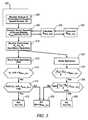
- FIG. 2is a schematic diagram of an exemplary architecture for a control system and powertrain, in accordance with an embodiment of the present invention
- FIG. 3is an algorithmic flowchart, in accordance with an embodiment of the present invention.
- FIGS. 1 and 2depict a system comprising an engine 14 , transmission 10 , driveline 90 , control system, and hydraulic control circuit (not separately illustrated) which has been constructed in accordance with an embodiment of the present invention.
- Mechanical aspects of the exemplary transmission 10are disclosed in detail in commonly assigned U.S. Pat. No. 6,953,409, which is incorporated herein by reference.
- the exemplary two-mode, compound-split, electro-mechanical hybrid transmission embodying the concepts of the present inventionis depicted in FIG. 1 .
- the transmission 10includes an input shaft 12 having an input speed, N I that is preferably driven by the internal combustion engine 14 , and an output shaft 64 having an output rotational speed, N O .
- the rotational speed of the output shaft 64is preferably monitored using a sensing system 84 , comprising a multi-tooth wheel and a sensing element.
- the multi-tooth wheelis preferably rotatably attached to the output shaft and comprises a device having a plurality of teeth and corresponding detents that are located around a circumference thereof.
- the sensing elementpreferably comprises a Hall-effect sensing device mounted in a fixed location adjacent the multi-tooth wheel.
- the sensing elementis operative to sense the teeth and corresponding detents in the multi-tooth wheel as the output shaft rotates, and generate an electrical pulse signal at each transition in the wheel between a tooth and a detent.
- Rotational speedis determined based upon the number of electrical pulses generated by the sensor over a predetermined elapsed period of time, which is interpretable by a control module, in this application a transmission control module (‘TCM’) 17 .
- TCMtransmission control module
- the sensing elementis preferably configured to generate the electrical pulse output such that rotational direction can be interpreted therefrom. In the embodiment described, when the output shaft 64 is rotating in a direction resulting in forward propulsion of the vehicle, the electrical pulse has a duration of approximately 45 microseconds.
- the electrical pulsehas a duration of approximately 180 microseconds.
- the control moduleregularly and ongoingly monitors duration of one or more signal pulse to determine rotational direction of the output shaft 64 .
- the exemplary engine 14comprises a multi-cylinder internal combustion engine selectively operative in several states to transmit torque to the transmission via shaft 12 , and can be either a spark-ignition or a compression-ignition engine.
- the engine 14has a crankshaft having characteristic speed N E which is operatively connected to the transmission input shaft 12 .
- the output of the engine, comprising speed N E and output torque T Ecan differ from transmission input speed N I and engine input torque T I when a torque management device (not shown) is placed therebetween.
- the transmission 10utilizes three planetary-gear sets 24 , 26 and 28 , and four torque-transmitting devices, i.e., clutches C 1 70 , C 2 62 , C 3 73 , and C 4 75 .
- An electro-hydraulic control system 42preferably controlled by transmission control module (TCM) 17 , is operative to control actuation and deactivation of the clutches.
- Clutches C 2 and C 4preferably comprise hydraulically-actuated rotating friction clutches.
- Clutches C 1 and C 3preferably comprise comprising hydraulically-actuated stationary devices grounded to the transmission case 68 .
- Each clutchis preferably hydraulically actuated, receiving pressurized hydraulic fluid from a pump via an electro-hydraulic control circuit.
- MG-AThere is a first electric machine comprising a motor/generator 56 , referred to as MG-A
- MG-Boperatively connected to the transmission via the planetary gears.
- Each of the machinesincludes a stator, a rotor, and a resolver assembly 80 , 82 .
- the stator for each machineis grounded to outer transmission case 68 , and includes a stator core with coiled electrical windings extending therefrom.
- the rotor for MG-A 56is supported on a hub plate gear that is operably attached to output shaft 60 via carrier 26 .
- the rotor for MG-B 72is attached to sleeve shaft hub 66 .
- Each resolver assembly 80 , 82is appropriately positioned and assembled on MG-A 56 and MG-B 72 .
- Each resolver assembly 80 , 82comprises a known variable reluctance device including a resolver stator, operably connected to the stator of each electric machine, and a resolver rotor, operably connected to the rotor of each electric machine.
- Each resolver 80 , 82comprises a sensing device adapted to sense rotational position of the resolver stator relative to the resolver rotor, and identify the rotational position. Signals output from the resolvers are interpreted to provide rotational speeds for MG-A 56 and MG-B 72 , referred to as N A and N B .
- Transmission output shaft 64is operably connected to a vehicle driveline 90 to provide motive output torque, T O to vehicle wheels.
- the driveline 90comprises a transfer case 96 having a known axle ratio, which transmits torque to vehicle drive wheels.
- Each wheel of the vehicleincluding the drive wheels and driven wheels, has a wheel speed sensing system 94 comprising one or more speed sensing devices mounted at the wheel and adapted to measure rotational speed of the respective wheel, including right-front (RF), right-rear (RR), left-front (LF), and left-rear (LR) wheels.
- the output of each wheel speed sensing system 94is monitored by a brake control module (‘BrCM’) 33 .
- the transmission 10receives input torque from the torque-generative devices, including the engine 14 , and MG-A 56 and MG-B 72 , referred to as ‘T I ’, ‘T A ’, and ‘T B ’ respectively, as a result of energy conversion from fuel or electrical potential stored in an electrical energy storage device (ESD) 74 .
- the ESD 74is high voltage DC-coupled to transmission power inverter module (TPIM) 19 via DC transfer conductors 27 .
- TPIM 19is an element of the control system described hereinafter with regard to FIG. 2 .
- the TPIM 19transmits electrical energy to and from MG-A 56 by transfer conductors 29 , and the TPIM 19 similarly transmits electrical energy to and from MG-B 72 by transfer conductors 31 . Electrical current is transmitted to and from the ESD 74 in accordance with whether the ESD 74 is being charged or discharged.
- TPIM 19includes the pair of power inverters and respective motor control modules configured to receive motor control commands and control inverter states therefrom for providing motor drive or regeneration functionality.
- MG-A 56 and MG-B 72are three-phase AC machines each having a rotor operable to rotate within a stator that is mounted on a case of the transmission.
- the inverterscomprise known complementary three-phase power electronics devices.
- FIG. 2a schematic block diagram of the control system, comprising a distributed control module architecture, is shown.
- the elements described hereinaftercomprise a subset of an overall vehicle control architecture, and are operable to provide coordinated system control of the powertrain system described herein.
- the control systemis operable to synthesize pertinent information and inputs, and execute algorithms to control various actuators to achieve control targets, including such parameters as fuel economy, emissions, performance, driveability, and protection of hardware, including batteries of ESD 74 and MG-A 56 and MG-B 72 .
- the distributed control module architectureincludes engine control module (ECM) 23 , transmission control module (TCM) 17 , battery pack control module (BPCM) 21 , and TPIM 19 , and the BrCM 33 .
- ECMengine control module
- TCMtransmission control module
- BPCMbattery pack control module
- TPIM 19TPIM 19
- a hybrid control module (HCP) 5provides overarching control and coordination of the aforementioned control modules.
- UIUser Interface
- UI 13operably connected to a plurality of devices through which a vehicle operator typically controls or directs operation of the powertrain including the transmission 10 , including an operator torque request (To_req) and operator brake request (BRAKE).
- Exemplary vehicle input devices to the UI 13include an accelerator pedal, a brake pedal, a transmission gear selector, and, a vehicle speed cruise control system.
- Each of the aforementioned control modulescommunicates with other control modules, sensors, and actuators via a local area network (LAN) bus 6 .
- the LAN bus 6allows for structured communication of control parameters and commands among the various control modules.
- the specific communication protocol utilizedis application-specific.
- the LAN bus and appropriate protocolsprovide for robust messaging and multi-control module interfacing between the aforementioned control modules, and other control modules providing functionality such as antilock braking, traction control, and vehicle stability.
- the HCP 5provides overarching control of the hybrid powertrain system, serving to coordinate operation of the ECM 23 , TCM 17 , TPIM 19 , and BPCM 21 , including communicating with the BrCM. Based upon various input signals from the UT 13 and the powertrain, including the battery pack, the HCP 5 generates various commands, including: the operator torque request (T O — REQ ), the engine input torque T I , clutch torque, (T CL — N ) for the N various torque-transfer clutches C 1 , C 2 , C 3 , C 4 of the transmission 10 ; and motor torques T A and T B for MG-A 56 and MG-B 72 .
- the TCM 17is operatively connected to the electro-hydraulic control circuit 42 , including for monitoring various pressure sensing devices (not shown) and generating and executing control signals for various solenoids to control pressure switches and control valves contained therein.
- the ECM 23is operably connected to the engine 14 , and functions to acquire data from a variety of sensors and control a variety of actuators, respectively, of the engine 14 over a plurality of discrete lines collectively shown as aggregate line 35 .
- the ECM 23receives the engine input torque command from the HCP 5 , and generates a desired axle torque, and an indication of actual engine input torque, T I , to the transmission, which is communicated to the HCP 5 .
- ECM 23is shown generally having bi-directional interface with engine 14 via aggregate line 35 .
- Various other parameters that may be sensed by ECM 23include engine coolant temperature, engine input speed, N E , to shaft 12 (which translate to transmission input speed, N I ) manifold pressure, ambient air temperature, and ambient pressure.
- Various actuators that may be controlled by the ECM 23include fuel injectors, ignition modules, and throttle control modules.
- the TCM 17is operably connected to the transmission 10 and functions to acquire data from a variety of sensors and provide command signals to the transmission. Inputs from the TCM 17 to the HCP 5 include estimated clutch torques (T CL — N ) for each of the N clutches, i.e., C 1 , C 2 , C 3 , and C 4 , and rotational output speed, N O , of the output shaft 64 . Other actuators and sensors may be used to provide additional information from the TCM to the HCP for control purposes.
- the TCM 17monitors inputs from pressure switches and selectively actuates pressure control solenoids and shift solenoids to actuate various clutches to achieve various transmission operating modes, as described hereinbelow.
- the BPCM 21is signally connected one or more sensors operable to monitor electrical current or voltage parameters of the ESD 74 to provide information about the state of the batteries to the HCP 5 .
- Such informationincludes battery state-of-charge, amp-hour throughput, battery temperature, battery voltage and available battery power.
- the BrCM 33executes vehicle functions related to braking control, traction control, and vehicle acceleration management.
- the BrCMis signally connected to the wheel speed sensors 94 and functions to acquire data therefrom and determines absolute wheel speeds, N WHL , for each of the wheels, which it communicates to the TCM and other controllers via the LAN.
- Each of the aforementioned control modulesis preferably a general-purpose digital computer generally comprising a microprocessor or central processing unit, storage mediums comprising read only memory (ROM), random access memory (RAM), electrically programmable read only memory (EPROM), high speed clock, analog to digital (A/D) and digital to analog (D/A) circuitry, and input/output circuitry and devices (I/O) and appropriate signal conditioning and buffer circuitry.
- Each control modulehas a set of control algorithms, comprising resident program instructions and calibrations stored in ROM and executed to provide the respective functions of each computer. Information transfer between the various computers is preferably accomplished using the aforementioned LAN 6 .
- Algorithms for control and state estimation in each of the control modulesare typically executed during preset loop cycles such that each algorithm is executed at least once each loop cycle.
- Algorithms stored in the non-volatile memory devicesare executed by one of the central processing units and are operable to monitor inputs from the sensing devices and execute control and diagnostic routines to control operation of the respective device, using preset calibrations.
- Loop cyclesare typically executed at regular intervals, for example each 3.125, 6.25, 12.5, 25 and 100 milliseconds during ongoing engine and vehicle operation. Alternatively, algorithms may be executed in response to occurrence of an event.
- the exemplary two-mode, compound-split, electro-mechanical transmissionoperates in one of several operating range states comprising fixed gear operation and continuously variable operation, described with reference to Table 1, below.
- a first continuously variable operating range statei.e., Mode I
- a second continuously variable operating range statei.e., Mode II
- Mode IIis selected when clutch C 1 70 is released and clutch C 2 62 is simultaneously actuated to connect the shaft 60 to the carrier of the third planetary gear set 28 .
- the engine 14can be either on or off.
- Engine Offis defined by engine input speed, N E , being equal to zero revolutions per minute (RPM), i.e., the engine crankshaft is not rotating.
- RPMrevolutions per minute
- Other factors outside the scope of this disclosureaffect when the electric machines MG-A 56 and MG-B 72 operate as motors and generators, and are not discussed herein.
- Mode I and Mode IIare characterized by single clutch applications, i.e., either clutch C 1 62 or C 2 70 , and by the controlled speed and torque of the electric machines MG-A 56 and MG-B 72 , which can be referred to as a continuously variable transmission mode.
- Certain operating rage statesare described below in which fixed gear ratios are achieved by applying an additional clutch.
- This additional clutchmay be clutch C 3 73 or C 4 75 , as shown in the table, above.
- N I /N Ofixed gear operation of input-to-output speed of the transmission
- N A and N Bare dependent on internal rotation of the mechanism as defined by the clutching and proportional to the input speed measured at shaft 12 .
- the rotational speeds, N A and N Bare directional in nature, such that a positive sign in the speed of either of the machines corresponds to a positive direction translating to forward movement of the vehicle and a negative sign in the speed of either of the machines corresponds to a negative direction translating to reverse movement of the vehicle.
- the supervisory HCP control module 5 and one or more of the other control modulesdetermine the operator torque request to be executed at shaft 64 .
- Final vehicle accelerationis affected by other factors, including, e.g., road load, road grade, and vehicle mass.
- the transmission operating range stateis determined for the exemplary transmission based upon a variety of operating characteristics of the powertrain. This includes an operator demand for torque, typically communicated through inputs to the UI 13 as previously described. Additionally, a demand for output torque is predicated on external conditions, including, e.g., road grade, road surface conditions, or wind load.
- the transmission operating range statemay be predicated on a powertrain torque demand caused by a control module command to operate one of the electric machines as an electrical generator or as an electric motor.
- the transmission operating range statecan be determined by an optimization algorithm or routine operable to determine optimum system efficiency based upon operator demand for power, battery state of charge, and energy efficiencies of the engine 14 and MG-A 56 and MG-B 72 .
- the control systemmanages torque inputs from the engine 14 and MG-A 56 and MG-B 72 based upon an outcome of the executed optimization routine, and system optimization occurs to optimize system efficiencies to improve fuel economy and manage battery charging. Furthermore, operation can be determined based upon a fault in a component or system.
- the HCP 5monitors the parametric states of the torque-generative devices, and determines the output of the transmission required to arrive at the desired torque output, as described hereinbelow. Under the direction of the HCP 5 , the transmission 10 operates over a range of output speeds from slow to fast in order to meet the operator demand.
- the energy storage system and electric machines MG-A 56 and MG-B 72are electrically-operatively coupled for power flow therebetween. Furthermore, the engine, the electric machines, and the electro-mechanical transmission are mechanically-operatively coupled to transmit power therebetween to generate a power flow to the output.
- the transmissionoperates as an input-split electrically variable transmission (EVT).
- EVTelectrically variable transmission
- Mode II operationthe transmission operates as a compound-split EVT.
- the control systemWhile operating in either of these two modes, the control system performs closed loop control on an engine speed which optimizes fuel economy while still meeting the torque request and given power constraints. It then commands motor speeds to vary the input-to-output speed ratio to accelerate the vehicle, in response to the operator torque request.
- the transmissionalso has the capability of achieving one of four fixed gear ratios. While operating in a fixed gear, the vehicle acts as a parallel hybrid and the motors are used only for boosting and braking/regeneration the vehicle.
- an operating modei.e., one of the fixed gear and continuously variable operating range states is determined for the exemplary transmission based upon a variety of operating characteristics of the powertrain. This includes an operator torque request, typically communicated through inputs to the UI 13 as previously described. Additionally, a demand for output torque is predicated on external conditions, including, e.g., road grade, road surface conditions, or wind load. The operating mode may be predicated on a powertrain torque demand caused by a control module command to operate of the electric machines in an electrical energy generating mode or in a torque generating mode.
- the operating modecan be determined by an optimization algorithm or routine operable to determine optimum system efficiency based upon operator demand for power, battery state of charge, and energy efficiencies of the engine 14 and MG-A 56 and MG-B 72 .
- the control systemmanages torque inputs from the engine 14 and MG-A 56 and MG-B 72 based upon an outcome of the executed optimization routine, and system optimization occurs to optimize system efficiencies to improve fuel economy and manage battery charging. Furthermore, operation can be determined based upon a fault in a component or system.
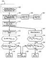
- FIG. 3depicts a flowchart 300 , representing algorithms executed in the various control modules.
- the algorithmsact to monitor a sensing system adapted to monitor output of the electro-mechanical transmission, depicted herein as monitoring rotational speed, N O , of the output shaft 64 using sensing system 84 .
- the algorithmsare preferably executed during each 25 ms loop cycle, and preferably executed in a manner to achieve a decision with regard to presence of a fault within 200 milliseconds of its occurrence.
- the signal output from the transmission output speed sensor 84is monitored ( 302 ).
- Output of a first sensoris monitored ( 304 ), comprising the signal output, N WHL , from one or more of the wheel speed sensors 94 , preferably the driven wheels, i.e., those operatively connected to the driveline 90 operatively connected to the output shaft 64 of the electro-mechanical transmission.
- An average wheel speed, N WHL — AVGis determined based upon the inputs from the wheel speed sensors ( 306 ).
- An adjusted average wheel speed, N WHL — AVGis determined based upon the inputs from the wheel speed sensors, adjusted based upon gear reductions occurring through the transfer case 96 , typically referred to as an axle ratio ( 308 ).
- the powertrain operationis monitored, to determine the input speed, N I , the speeds of the electric motors N A , N B , and the transmission operating range state, i.e., one of MI, MIT, FG 1 , FG 2 , FG 3 , FG 4 ( 310 ).
- a first expected output of the transmissionis determined based upon the output of the wheel speed sensors, and typically comprises the adjusted average wheel speed, N WHL — ADJ .
- a second expected output of the transmissionis determined, based upon the operation of the powertrain.
- the second expected outputis determined based upon the input speed from the engine and the fixed gear ratio, i.e., N I ⁇ GR, and compared to the first expected output, N WHL — ADJ ( 314 ).
- an average (AVG) of the first and second expected outputsis calculated and the rotational speed, N O , of the output shaft 64 determined using sensing system 84 is compared therewith ( 316 ).
- the control systemuses the rotational speed, N O , of the output shaft 64 using sensing system 84 for various engine and powertrain control operations ( 318 ).
- the control systemuses the adjusted average wheel speed, N WHL — ADJ , as a substitute the output speed for various engine and powertrain control operations ( 320 ).
- the second expected outputis determined based upon the average rotational speed of the electric machines, i.e., (N A +N B )/2, and compared to the first expected output, N WHL — ADJ ( 324 ).
- N A +N Bthe first expected output
- N WHL — ADJthe first expected output
- an average of the first and second expected outputsis determined, and compared to the rotational speed, N O , of the output shaft 64 determined using sensing system 84 ( 326 ).
- the control systemuses the rotational speed, N O , of the output shaft 64 using sensing system 84 for various engine and powertrain control operations ( 328 ).
- the control systemuses the adjusted average wheel speed, N WHL — ADJ , as substitute for the output speed for various engine and powertrain control operations ( 320 ).
- N OThe rotational direction of the transmission output speed, N O , is also determined, under all operating conditions, by mathematically adding the signed rotational speeds of the electric machines and determining the sign of the resultant: N A +N B ,
- a positive resultant of adding the numberscorresponds to forward direction
- a negative resultant of adding the numberscorresponds to reverse direction.
- the direction of the electrical pulse outputis compared to the resultant sum of the motor speeds to determine whether the directional output from the sensor is correct. This is used to monitor the sensor and identify a fault associated therewith.
Landscapes
- Engineering & Computer Science (AREA)
- General Engineering & Computer Science (AREA)
- Mechanical Engineering (AREA)
- Electric Propulsion And Braking For Vehicles (AREA)
- Hybrid Electric Vehicles (AREA)
Abstract
Description
| TABLE 1 | ||||
| Transmission Operating | ||||
| Range State (Op_range) | Actuated Clutches | |||
| Mode I - (MI) | ||||
| Fixed Gear Ratio 1 (FG1) | ||||
| Fixed Gear Ratio 2 (FG2) | ||||
| Mode II - (MII) | ||||
| Fixed Gear Ratio 3 (FG3) | ||||
| Fixed Gear Ratio 4 (FG4) | ||||
NO=NI×GR.
NO=(NA+NB)/2.
NA+NB,
Claims (15)
Priority Applications (3)
| Application Number | Priority Date | Filing Date | Title |
|---|---|---|---|
| US11/854,564US8027771B2 (en) | 2007-09-13 | 2007-09-13 | Method and apparatus to monitor an output speed sensor during operation of an electro-mechanical transmission |
| DE102008046524.0ADE102008046524B4 (en) | 2007-09-13 | 2008-09-10 | Method for monitoring an output speed sensor during the operation of an electromechanical transmission |
| CN2008101608199ACN101386268B (en) | 2007-09-13 | 2008-09-16 | Method and apparatus to monitor an output speed sensor during operation of an electro-mechanical transmission |
Applications Claiming Priority (1)
| Application Number | Priority Date | Filing Date | Title |
|---|---|---|---|
| US11/854,564US8027771B2 (en) | 2007-09-13 | 2007-09-13 | Method and apparatus to monitor an output speed sensor during operation of an electro-mechanical transmission |
Publications (2)
| Publication Number | Publication Date |
|---|---|
| US20090076679A1 US20090076679A1 (en) | 2009-03-19 |
| US8027771B2true US8027771B2 (en) | 2011-09-27 |
Family
ID=40455447
Family Applications (1)
| Application Number | Title | Priority Date | Filing Date |
|---|---|---|---|
| US11/854,564Expired - Fee RelatedUS8027771B2 (en) | 2007-09-13 | 2007-09-13 | Method and apparatus to monitor an output speed sensor during operation of an electro-mechanical transmission |
Country Status (3)
| Country | Link |
|---|---|
| US (1) | US8027771B2 (en) |
| CN (1) | CN101386268B (en) |
| DE (1) | DE102008046524B4 (en) |
Cited By (3)
| Publication number | Priority date | Publication date | Assignee | Title |
|---|---|---|---|---|
| US20100292900A1 (en)* | 2008-01-22 | 2010-11-18 | Yuya Shimozato | Control apparatus and control method for continuously variable transmission |
| US20130138322A1 (en)* | 2011-11-08 | 2013-05-30 | Thales | Full authority digital engine control system for aircraft engine |
| US9218695B2 (en) | 2012-12-27 | 2015-12-22 | Robert Bosch Gmbh | System and method for monitoring an estimated wheel speed of a vehicle using a transmission output shaft sensor |
Families Citing this family (20)
| Publication number | Priority date | Publication date | Assignee | Title |
|---|---|---|---|---|
| DE102007035722A1 (en)* | 2007-07-30 | 2009-02-05 | Robert Bosch Gmbh | Method and device for specifying an output variable of a drive unit |
| US7867135B2 (en)* | 2007-09-26 | 2011-01-11 | GM Global Technology Operations LLC | Electro-mechanical transmission control system |
| US8306709B2 (en)* | 2008-09-09 | 2012-11-06 | GM Global Technology Operations LLC | Engagement of selectable one-way clutch or mechanical diode by active engine speed control |
| US8417411B2 (en)* | 2009-04-22 | 2013-04-09 | GM Global Technology Operations LLC | Torque sensor performance diagnostic systems and methods |
| JP2013043575A (en)* | 2011-08-25 | 2013-03-04 | Nissan Motor Co Ltd | Failure determination device of vehicle system |
| US8473134B1 (en)* | 2012-02-07 | 2013-06-25 | GM Global Technology Operations LLC | Method and apparatus for operating a vehicle including a hybrid powertrain system during a launch maneuver |
| CN104228824B (en)* | 2013-06-19 | 2018-10-26 | 上海汽车集团股份有限公司 | A kind of electrically driven speed change case output shaft sensor reasonability method of discrimination and its system |
| CN103851179B (en)* | 2014-02-27 | 2016-08-17 | 长城汽车股份有限公司 | Vehicle and control method thereof and control device |
| CN103914889B (en)* | 2014-04-02 | 2016-05-04 | 北京中交慧联信息科技有限公司 | A kind of system and method that the collection behavior of car speed is carried out to abnormality detection |
| CN104132809B (en)* | 2014-08-02 | 2016-08-17 | 山东交通学院 | A kind of engine bench test system of composite automobile automatic transmission |
| CN104632936B (en)* | 2014-12-10 | 2017-06-23 | 陕西法士特齿轮有限责任公司 | A kind of clutch control method of automatic mechanical type gearbox |
| FR3048568B1 (en)* | 2016-03-07 | 2018-03-09 | Renault S.A.S | METHOD AND SYSTEM FOR CONTROLLING AN ELECTRIC MOTOR IN THE EVENT OF ROTOR POSITION SIGNAL FAILURE |
| CN107882816B (en)* | 2016-09-30 | 2020-03-31 | 比亚迪股份有限公司 | Fault diagnosis and fault tolerance method and system for hydraulic control system of automatic gearbox |
| WO2019004167A1 (en)* | 2017-06-28 | 2019-01-03 | ジヤトコ株式会社 | Control device for automatic transmission and control method for automatic transmission |
| KR102334659B1 (en)* | 2017-06-29 | 2021-12-03 | 현대모비스 주식회사 | Apparatus and method for detecting faults in in-wheel driving system of vehicle |
| EP3670963A1 (en)* | 2018-12-20 | 2020-06-24 | Ningbo Geely Automobile Research & Development Co. Ltd. | A transmission for a vehicle |
| CN110173562A (en)* | 2019-04-10 | 2019-08-27 | 东风商用车有限公司 | A kind of application method of AMT output shaft speed sensor |
| US12311773B2 (en)* | 2021-12-20 | 2025-05-27 | Dana Motion Systems Italia S.R.L. | Methods and systems for ensuring compliance of an electric vehicle |
| CN117162944B (en)* | 2023-09-12 | 2025-08-01 | 中国第一汽车股份有限公司 | Method for determining rotation speed of vehicle output shaft, vehicle and storage medium |
| CN120520972A (en)* | 2025-07-22 | 2025-08-22 | 盛瑞传动股份有限公司 | Vehicle control method, device, equipment and medium |
Citations (109)
| Publication number | Priority date | Publication date | Assignee | Title |
|---|---|---|---|---|
| US4849899A (en)* | 1986-04-07 | 1989-07-18 | Eaton Corporation | Method for controlling AMT system including speed sensor signal fault detection and tolerance |
| US5896083A (en)* | 1997-05-16 | 1999-04-20 | Detroit Diesel Corporation | System and method for detecting vehicle speed sensor tampering |
| US6193628B1 (en)* | 1999-08-17 | 2001-02-27 | Ford Global Technologies, Inc. | Vehicle shift quality using a supplemental torque source |
| US20020013195A1 (en)* | 1998-11-20 | 2002-01-31 | Hitachi, Ltd. | Control unit and control method of automatic transmission and automotive vehicle |
| US20020123836A1 (en)* | 2001-03-01 | 2002-09-05 | Nissan Motor Co., Ltd. | Vehicle drive system and vehicle controlling method |
| US20030190995A1 (en)* | 2000-11-13 | 2003-10-09 | Honda Giken Kogyo Kabushiki Kaisha | Control apparatus for controlling transmission of hybrid vehicle |
| US20040200654A1 (en)* | 2003-04-09 | 2004-10-14 | Nissan Motor Co., Ltd. | Drive apparatus for vehicle |
| US6832148B1 (en) | 2003-10-14 | 2004-12-14 | General Motors Corporation | Automatic engine stop and restart mode for reducing emissions of a hybrid electric vehicle |
| US6834217B2 (en)* | 1999-12-08 | 2004-12-21 | Robert Bosch Gmbh | Method and device for determining a speed variable of at least one driven wheel of a motor vehicle |
| US6868318B1 (en) | 2003-10-14 | 2005-03-15 | General Motors Corporation | Method for adjusting battery power limits in a hybrid electric vehicle to provide consistent launch characteristics |
| US20050076958A1 (en) | 2003-10-14 | 2005-04-14 | Foster Michael D. | Control apparatus, method and diagnostic for hydraulic fill and drain |
| US20050080537A1 (en) | 2003-10-14 | 2005-04-14 | Cawthorne William R. | Optimal selection of input torque considering battery utilization for a hybrid electric vehicle |
| US20050080523A1 (en) | 2003-10-14 | 2005-04-14 | Bennett Adam C. | Silent operating mode for reducing emissions of a hybrid electric vehicle |
| US20050080541A1 (en) | 2003-10-14 | 2005-04-14 | Sah Jy-Jen F. | Two clutch fixed-ratio exit control for multi-mode hybrid drive |
| US20050080539A1 (en) | 2003-10-14 | 2005-04-14 | Hubbard Gregory A. | Method for determining preferred input operating points for a vehicle transmission |
| US20050077867A1 (en) | 2003-10-14 | 2005-04-14 | Cawthorne William R. | Method of determining battery power limits for an energy storage system of a hybrid electric vehicle |
| US20050080538A1 (en) | 2003-10-14 | 2005-04-14 | Hubbard Gregory A. | Real-time operating parameter selection in a vehicular transmission |
| US20050077877A1 (en) | 2003-10-14 | 2005-04-14 | Cawthorne William R. | Managing service life of a battery |
| US20050080540A1 (en) | 2003-10-14 | 2005-04-14 | Steinmetz Todd M. | Synchronous shift control in an electrically variable transmission |
| US20050080535A1 (en) | 2003-10-14 | 2005-04-14 | Steinmetz Todd M. | Speed control for an electrically variable transmission |
| US20050080527A1 (en) | 2003-10-14 | 2005-04-14 | Tao Xuefeng T. | Hybrid transmission member speed determination, sensor diagnostics and fault recovery |
| US6896078B2 (en)* | 2003-01-31 | 2005-05-24 | Victor Company Of Japan, Ltd | Movable robot |
| US20050182526A1 (en) | 2004-02-14 | 2005-08-18 | Hubbard Gregory A. | Optimal selection of input torque with stability of power flow for a hybrid electric vehicle |
| US20050182543A1 (en) | 2004-02-14 | 2005-08-18 | Sah Jy-Jen F. | Shift through neutral control in an electrically variable transmission |
| US20050182547A1 (en) | 2004-02-14 | 2005-08-18 | Sah Jy-Jen F. | Shift inhibit control for multi-mode hybrid drive |
| US20050182546A1 (en) | 2004-02-14 | 2005-08-18 | Tung-Ming Hsieh | Throttle phase out control |
| US20050189918A1 (en) | 2004-02-14 | 2005-09-01 | Weisgerber Scott T. | Energy storage system state of charge diagnostic |
| US6953409B2 (en)* | 2003-12-19 | 2005-10-11 | General Motors Corporation | Two-mode, compound-split, hybrid electro-mechanical transmission having four fixed ratios |
| US20050252305A1 (en) | 2004-05-15 | 2005-11-17 | Hubbard Gregory A | Method for dynamically determining peak output torque in an electrically variable transmission |
| US20050255963A1 (en) | 2004-05-14 | 2005-11-17 | Tung-Ming Hsieh | Single motor recovery for an electrically variable transmission |
| US20050255968A1 (en) | 2004-05-14 | 2005-11-17 | Sah Jy-Jen F | Method for active engine stop of a hybrid electric vehicle |
| US20050256618A1 (en) | 2004-05-14 | 2005-11-17 | Tung-Ming Hsieh | Method of testing motor torque integrity in a hybrid electric vehicle |
| US20050256631A1 (en) | 2004-05-14 | 2005-11-17 | Cawthorne William R | Method of determining engine output power in a hybrid electric vehicle |
| US20050255966A1 (en) | 2004-05-14 | 2005-11-17 | Tao Xuefeng T | Engine retard operation scheduling and management in a hybrid vehicle |
| US20050256623A1 (en) | 2004-05-15 | 2005-11-17 | Hubbard Gregory A | Method for dynamically determining peak output torque within battery constraints in a hybrid transmission including a parallel hybrid split |
| US20050256919A1 (en) | 2004-05-14 | 2005-11-17 | Cawthorne William R | Method of determining the derivative of an input signal |
| US20050252474A1 (en) | 2004-05-14 | 2005-11-17 | Sah Jy-Jen F | Multi-stage compression ignition engine start |
| US20050252283A1 (en) | 2004-05-14 | 2005-11-17 | Heap Anthony H | Diagnostic method for a torque control of an electrically variable transmission |
| US20050256626A1 (en) | 2004-05-14 | 2005-11-17 | Tung-Ming Hsieh | Method and apparatus to control hydraulic pressure in an electrically variable transmission |
| US20050255965A1 (en) | 2004-05-14 | 2005-11-17 | Tao Xuefeng T | Coordinated regenerative and engine retard braking for a hybrid vehicle |
| US20050256629A1 (en) | 2004-05-14 | 2005-11-17 | Tao Xuefeng T | Method for automatic traction control in a hybrid electric vehicle |
| US20050256627A1 (en) | 2004-05-14 | 2005-11-17 | Sah Jy-Jen F | Acceleration limiting for a vehicle |
| US20050255967A1 (en) | 2004-05-14 | 2005-11-17 | Foster Michael D | Method of automatically flushing debris from an electrically-operated hydraulic valve |
| US20050256617A1 (en) | 2004-05-14 | 2005-11-17 | Cawthorne William R | Method of undervoltage protection during engine cranking |
| US20050256633A1 (en) | 2004-05-15 | 2005-11-17 | Heap Anthony H | Cost structure method including fuel economy and engine emission considerations |
| US20050255964A1 (en) | 2004-05-15 | 2005-11-17 | Heap Anthony H | Method of providing electric motor torque reserve in a hybrid electric vehicle |
| US20050256625A1 (en) | 2004-05-15 | 2005-11-17 | Sah Jy-Jen F | Hydraulic clutch state diagnostic and control |
| US20060017414A1 (en)* | 2004-07-21 | 2006-01-26 | Nissan Motor Co., Ltd. | Motor torque control apparatus and method for automotive vehicle |
| US7024290B2 (en)* | 2004-07-30 | 2006-04-04 | Ford Global Technologies, Llc | Active motor damping to mitigate electric vehicle driveline oscillations |
| US20060207810A1 (en)* | 2002-09-13 | 2006-09-21 | Daimlerchrysler Ag | Hybrid drive |
| US20060276289A1 (en)* | 2005-06-03 | 2006-12-07 | Nissan Motor Co., Ltd. | Vehicle drive control apparatus and method |
| US7154236B1 (en) | 2006-02-13 | 2006-12-26 | Gm Global Technology Operations, Inc. | Control system for hybrid powertrain |
| US20070099739A1 (en) | 2005-10-31 | 2007-05-03 | Foster Michael D | Multiplexed pressure switch system for an electrically variable hybrid transmission |
| US20070149348A1 (en) | 2005-12-23 | 2007-06-28 | Holmes Alan G | Vehicle propulsion system |
| US20070179014A1 (en)* | 2006-02-01 | 2007-08-02 | Toyota Jidosha Kabushiki Kaisha | Power output apparatus, vehicle including power output apparatus, and control unit and method for power output apparatus |
| US20070191181A1 (en) | 2006-02-13 | 2007-08-16 | Burns Robert D | Method and apparatus for controlling vehicle rollback |
| US20070225889A1 (en)* | 2006-03-22 | 2007-09-27 | Morris Robert L | Jerk management using multivariable active driveline damping |
| US20070225887A1 (en)* | 2006-03-22 | 2007-09-27 | Morris Robert L | Method and apparatus for multivariate active driveline damping |
| US20070225886A1 (en) | 2006-03-22 | 2007-09-27 | Morris Robert L | Parameter state estimation |
| US20070225888A1 (en)* | 2006-03-22 | 2007-09-27 | Morris Robert L | Driveline lash estimation and clunk management using multivariable active driveline damping |
| US7286917B2 (en)* | 2005-05-04 | 2007-10-23 | Detroit Diesel Corporation | Method of detecting vehicle speed sensor failure |
| US20070260381A1 (en) | 2006-05-03 | 2007-11-08 | Sah Jy-Jen F | Synchronous shift execution for hybrid transmission |
| US20070276569A1 (en) | 2006-05-25 | 2007-11-29 | Sah Jy-Jen F | Method and apparatus to control an electro-mechanical transmission during shifting event |
| US20070284176A1 (en) | 2006-05-25 | 2007-12-13 | Sah Jy-Jen F | Method and apparatus to control hydraulic pressure in an electro-mechanical transmission |
| US20070284163A1 (en) | 2006-06-07 | 2007-12-13 | Heap Anthony H | Method and apparatus for control of a hybrid electric vehicle to achieve a target life objective for an energy storage device |
| US20070285060A1 (en) | 2006-06-07 | 2007-12-13 | Zettel Andrew M | Method and apparatus for determining the effect of temperature upon life expectancy of an electric energy storage device in a hybrid electric vehicle |
| US20070285059A1 (en) | 2006-06-07 | 2007-12-13 | Zettel Andrew M | Method and apparatus for real-time life estimation of an electric energy storage device |
| US20070285063A1 (en) | 2006-06-07 | 2007-12-13 | Zettel Andrew M | Method and apparatus for quantifying quiescent period temperature effects upon an electric energy storage device |
| US20070285097A1 (en) | 2006-06-07 | 2007-12-13 | Zettel Andrew M | Method and apparatus for predicting change in an operating state of an electric energy storage device |
| US20070285061A1 (en) | 2006-06-07 | 2007-12-13 | Zettel Andrew M | Method and apparatus for real-time life estimation of an electric energy storage device in a hybrid electric vehicle |
| US20070284162A1 (en) | 2006-06-07 | 2007-12-13 | Zettel Andrew M | Method for operating a hybrid electric powertrain based on predictive effects upon an electrical energy storage device |
| US20080004779A1 (en) | 2006-06-30 | 2008-01-03 | Sah Jy-Jen F | Apparatus and method to control transmission torque output during a gear-to-gear shift |
| US20080017427A1 (en)* | 2006-07-21 | 2008-01-24 | Nissan Motor Co., Ltd. | Hybrid vehicle control apparatus |
| US20080032855A1 (en) | 2006-08-04 | 2008-02-07 | Sah Jy-Jen F | Method and apparatus to control an electro-hydraulic transmission during shifting event |
| US20080028879A1 (en) | 2006-08-04 | 2008-02-07 | Robinette Richard E | Method and apparatus for fault-tolerant transmission gear selector lever position determination |
| US20080064562A1 (en) | 2006-09-13 | 2008-03-13 | Aettel Andrew M | Method and apparatus to monitor operation of an auxiliary hydraulic pump in a transmission |
| US20080064559A1 (en) | 2006-09-11 | 2008-03-13 | Cawthorne William R | Control system architecture for a hybrid powertrain |
| US7351182B2 (en)* | 2004-10-27 | 2008-04-01 | Aisin Aw Co., Ltd. | Drive apparatus for hybrid vehicle and control method thereof |
| US20080103003A1 (en) | 2006-10-26 | 2008-05-01 | Sah Jy-Jen F | Method and apparatus to control operation of a hydraulic control circuit for an electro-mechanical transmission |
| US20080119321A1 (en) | 2006-11-17 | 2008-05-22 | Heap Anthony H | Control architecture and method for two-dimensional optimization of input torque and motor torque in fixed gear for a hybrid powertrain system |
| US20080120001A1 (en) | 2006-11-17 | 2008-05-22 | Heap Anthony H | Control architecture for selection of optimal mode or gear and input speed for a hybrid powertrain system |
| US20080120002A1 (en) | 2006-11-17 | 2008-05-22 | Heap Anthony H | Control architecture and method for two-dimensional optimization of input speed and input torque in mode for a hybrid powertrain system |
| US20080119320A1 (en) | 2006-11-17 | 2008-05-22 | Wu Peter E | Method and apparatus for controlling an electro-mechanical transmission during a shift execution |
| US20080120000A1 (en) | 2006-11-17 | 2008-05-22 | Heap Anthony H | Control architecture for optimization and control of a hybrid powertrain system |
| US20080176706A1 (en) | 2007-01-24 | 2008-07-24 | Wu Peter E | Method and apparatus to control operation of an electro-mechanical transmission |
| US20080176709A1 (en) | 2007-01-24 | 2008-07-24 | Wu Peter E | Method and apparatus to monitor devices of a hydraulic circuit of an electro-mechanical transmission |
| US20080183372A1 (en) | 2007-01-31 | 2008-07-31 | Snyder Bryan R | Method and apparatus to determine pressure in an unfired cylinder |
| US20080182696A1 (en) | 2006-08-04 | 2008-07-31 | Sah Jy-Jen F | Method and apparatus to control operation of a hydraulic control circuit for an electro-mechanical transmission |
| US20080181280A1 (en) | 2007-01-31 | 2008-07-31 | Wang Wei D | Method and apparatus to monitor a temperature sensing device |
| US20080234097A1 (en) | 2007-03-20 | 2008-09-25 | Sah Jy-Jen F | Clutch control for hybrid transmission |
| US20080236921A1 (en) | 2007-03-29 | 2008-10-02 | Huseman Steven C | Method for controlling engine speed in a hybrid electric vehicle |
| US20080243346A1 (en) | 2007-03-29 | 2008-10-02 | Huseman Steven C | Method and apparatus for controlling power flow in a hybrid powertrain system |
| US20080249745A1 (en) | 2006-06-07 | 2008-10-09 | Heap Anthony H | Method and apparatus for management of an electric energy storage device to achieve a target life objective |
| US20080262694A1 (en) | 2007-04-19 | 2008-10-23 | Heap Anthony H | Method and apparatus to optimize engine warm up |
| US20080262698A1 (en) | 2007-04-19 | 2008-10-23 | Lahti John L | Method and apparatus to determine instantaneous engine power loss for a powertrain system |
| US20080272717A1 (en) | 2007-05-03 | 2008-11-06 | Gleason Sean E | Method and apparatus to determine rotational position of an electrical machine |
| US20080275624A1 (en) | 2007-05-03 | 2008-11-06 | Snyder Bryan R | Method and apparatus to control engine restart for a hybrid powertrain system |
| US20080275611A1 (en) | 2007-05-03 | 2008-11-06 | Snyder Bryan R | Method and apparatus to determine rotational position of an internal combustion engine |
| US20080275625A1 (en) | 2007-05-03 | 2008-11-06 | Snyder Bryan R | Method and apparatus to control engine stop for a hybrid powertrain system |
| US20080287255A1 (en) | 2007-05-14 | 2008-11-20 | Snyder Bryan R | Control architecture and method to evaluate engine off operation of a hybrid powertrain system operating in a continuously variable mode |
| US20090069989A1 (en) | 2007-09-11 | 2009-03-12 | Heap Anthony H | Method and control architecture for selection of optimal engine input torque for a powertrain system |
| US20090070019A1 (en) | 2007-09-11 | 2009-03-12 | Heap Anthony H | Method and control architecture for optimization of engine fuel-cutoff selection and engine input torque for a hybrid powertrain system |
| US20090069148A1 (en) | 2007-09-11 | 2009-03-12 | Heap Anthony H | Control architecture and method for one-dimensional optimization of input torque and motor torque in fixed gear for a hybrid powertrain system |
| US20090082170A1 (en) | 2007-09-26 | 2009-03-26 | Gm Global Technology Operations, Inc. | Method and control architecture for optimization of cylinder deactivation selection and engine input torque for a hybrid powertrain system |
| US20090088294A1 (en) | 2007-09-28 | 2009-04-02 | Gm Global Technology Operations, Inc. | Thermal protection of an electric drive system |
| US20090112412A1 (en) | 2007-10-31 | 2009-04-30 | Gm Global Technology Operations, Inc. | Method and apparatus to monitor output of an electro-mechanical transmission |
| US20090118917A1 (en) | 2007-11-07 | 2009-05-07 | Gm Global Technology Operations, Inc. | Method and apparatus to control launch of a vehicle having an electro-mechanical transmission |
| US20090144002A1 (en) | 2007-11-07 | 2009-06-04 | Gm Global Technology Operations, Inc. | Method and apparatus for detecting faults in a current sensing device |
| US7626382B2 (en)* | 2005-06-03 | 2009-12-01 | Toyota Jidosha Kabushiki Kaisha | Rotation speed detecting apparatus and automatic transmission controller having the apparatus |
Family Cites Families (4)
| Publication number | Priority date | Publication date | Assignee | Title |
|---|---|---|---|---|
| JP2002199885A (en)* | 2001-01-05 | 2002-07-16 | Kyowa Hakko Kogyo Co Ltd | β1,3-galactosyltransferase and DNA encoding the enzyme |
| US7629358B2 (en)* | 2004-03-17 | 2009-12-08 | Pfizer Inc | Compounds useful for the treatment of diseases |
| JP2007097089A (en)* | 2005-09-30 | 2007-04-12 | Yokogawa Electric Corp | Coding circuit and coding device |
| US8117335B2 (en)* | 2007-01-30 | 2012-02-14 | Oracle International Corporation | Service or application driven processing of network traffic using a smart router |
- 2007
- 2007-09-13USUS11/854,564patent/US8027771B2/ennot_activeExpired - Fee Related
- 2008
- 2008-09-10DEDE102008046524.0Apatent/DE102008046524B4/ennot_activeExpired - Fee Related
- 2008-09-16CNCN2008101608199Apatent/CN101386268B/ennot_activeExpired - Fee Related
Patent Citations (115)
| Publication number | Priority date | Publication date | Assignee | Title |
|---|---|---|---|---|
| US4849899A (en)* | 1986-04-07 | 1989-07-18 | Eaton Corporation | Method for controlling AMT system including speed sensor signal fault detection and tolerance |
| US5896083A (en)* | 1997-05-16 | 1999-04-20 | Detroit Diesel Corporation | System and method for detecting vehicle speed sensor tampering |
| US20020013195A1 (en)* | 1998-11-20 | 2002-01-31 | Hitachi, Ltd. | Control unit and control method of automatic transmission and automotive vehicle |
| US6193628B1 (en)* | 1999-08-17 | 2001-02-27 | Ford Global Technologies, Inc. | Vehicle shift quality using a supplemental torque source |
| US6834217B2 (en)* | 1999-12-08 | 2004-12-21 | Robert Bosch Gmbh | Method and device for determining a speed variable of at least one driven wheel of a motor vehicle |
| US20030190995A1 (en)* | 2000-11-13 | 2003-10-09 | Honda Giken Kogyo Kabushiki Kaisha | Control apparatus for controlling transmission of hybrid vehicle |
| US20020123836A1 (en)* | 2001-03-01 | 2002-09-05 | Nissan Motor Co., Ltd. | Vehicle drive system and vehicle controlling method |
| US20060207810A1 (en)* | 2002-09-13 | 2006-09-21 | Daimlerchrysler Ag | Hybrid drive |
| US6896078B2 (en)* | 2003-01-31 | 2005-05-24 | Victor Company Of Japan, Ltd | Movable robot |
| US20040200654A1 (en)* | 2003-04-09 | 2004-10-14 | Nissan Motor Co., Ltd. | Drive apparatus for vehicle |
| US6832148B1 (en) | 2003-10-14 | 2004-12-14 | General Motors Corporation | Automatic engine stop and restart mode for reducing emissions of a hybrid electric vehicle |
| US20050076958A1 (en) | 2003-10-14 | 2005-04-14 | Foster Michael D. | Control apparatus, method and diagnostic for hydraulic fill and drain |
| US20050080523A1 (en) | 2003-10-14 | 2005-04-14 | Bennett Adam C. | Silent operating mode for reducing emissions of a hybrid electric vehicle |
| US20050080541A1 (en) | 2003-10-14 | 2005-04-14 | Sah Jy-Jen F. | Two clutch fixed-ratio exit control for multi-mode hybrid drive |
| US20050080539A1 (en) | 2003-10-14 | 2005-04-14 | Hubbard Gregory A. | Method for determining preferred input operating points for a vehicle transmission |
| US20050077867A1 (en) | 2003-10-14 | 2005-04-14 | Cawthorne William R. | Method of determining battery power limits for an energy storage system of a hybrid electric vehicle |
| US20050080538A1 (en) | 2003-10-14 | 2005-04-14 | Hubbard Gregory A. | Real-time operating parameter selection in a vehicular transmission |
| US20050077877A1 (en) | 2003-10-14 | 2005-04-14 | Cawthorne William R. | Managing service life of a battery |
| US20050080540A1 (en) | 2003-10-14 | 2005-04-14 | Steinmetz Todd M. | Synchronous shift control in an electrically variable transmission |
| US20050080535A1 (en) | 2003-10-14 | 2005-04-14 | Steinmetz Todd M. | Speed control for an electrically variable transmission |
| US20050080527A1 (en) | 2003-10-14 | 2005-04-14 | Tao Xuefeng T. | Hybrid transmission member speed determination, sensor diagnostics and fault recovery |
| US20050080537A1 (en) | 2003-10-14 | 2005-04-14 | Cawthorne William R. | Optimal selection of input torque considering battery utilization for a hybrid electric vehicle |
| US7110869B2 (en)* | 2003-10-14 | 2006-09-19 | General Motors Corporation | Hybrid transmission member speed determination, sensor diagnostics and fault recovery |
| US20070078580A1 (en) | 2003-10-14 | 2007-04-05 | General Motors Corp. | Optimal selection of input torque considering battery utilization for a hybrid electric vehicle |
| US6868318B1 (en) | 2003-10-14 | 2005-03-15 | General Motors Corporation | Method for adjusting battery power limits in a hybrid electric vehicle to provide consistent launch characteristics |
| US6953409B2 (en)* | 2003-12-19 | 2005-10-11 | General Motors Corporation | Two-mode, compound-split, hybrid electro-mechanical transmission having four fixed ratios |
| US20050182546A1 (en) | 2004-02-14 | 2005-08-18 | Tung-Ming Hsieh | Throttle phase out control |
| US20050189918A1 (en) | 2004-02-14 | 2005-09-01 | Weisgerber Scott T. | Energy storage system state of charge diagnostic |
| US20050182547A1 (en) | 2004-02-14 | 2005-08-18 | Sah Jy-Jen F. | Shift inhibit control for multi-mode hybrid drive |
| US20050182543A1 (en) | 2004-02-14 | 2005-08-18 | Sah Jy-Jen F. | Shift through neutral control in an electrically variable transmission |
| US20050182526A1 (en) | 2004-02-14 | 2005-08-18 | Hubbard Gregory A. | Optimal selection of input torque with stability of power flow for a hybrid electric vehicle |
| US20050255963A1 (en) | 2004-05-14 | 2005-11-17 | Tung-Ming Hsieh | Single motor recovery for an electrically variable transmission |
| US20050256618A1 (en) | 2004-05-14 | 2005-11-17 | Tung-Ming Hsieh | Method of testing motor torque integrity in a hybrid electric vehicle |
| US20050255966A1 (en) | 2004-05-14 | 2005-11-17 | Tao Xuefeng T | Engine retard operation scheduling and management in a hybrid vehicle |
| US20050255968A1 (en) | 2004-05-14 | 2005-11-17 | Sah Jy-Jen F | Method for active engine stop of a hybrid electric vehicle |
| US20050256919A1 (en) | 2004-05-14 | 2005-11-17 | Cawthorne William R | Method of determining the derivative of an input signal |
| US20050252474A1 (en) | 2004-05-14 | 2005-11-17 | Sah Jy-Jen F | Multi-stage compression ignition engine start |
| US20050252283A1 (en) | 2004-05-14 | 2005-11-17 | Heap Anthony H | Diagnostic method for a torque control of an electrically variable transmission |
| US20050256626A1 (en) | 2004-05-14 | 2005-11-17 | Tung-Ming Hsieh | Method and apparatus to control hydraulic pressure in an electrically variable transmission |
| US20050255965A1 (en) | 2004-05-14 | 2005-11-17 | Tao Xuefeng T | Coordinated regenerative and engine retard braking for a hybrid vehicle |
| US20050256629A1 (en) | 2004-05-14 | 2005-11-17 | Tao Xuefeng T | Method for automatic traction control in a hybrid electric vehicle |
| US20050256627A1 (en) | 2004-05-14 | 2005-11-17 | Sah Jy-Jen F | Acceleration limiting for a vehicle |
| US20050255967A1 (en) | 2004-05-14 | 2005-11-17 | Foster Michael D | Method of automatically flushing debris from an electrically-operated hydraulic valve |
| US20050256617A1 (en) | 2004-05-14 | 2005-11-17 | Cawthorne William R | Method of undervoltage protection during engine cranking |
| US20050256631A1 (en) | 2004-05-14 | 2005-11-17 | Cawthorne William R | Method of determining engine output power in a hybrid electric vehicle |
| US20070093953A1 (en) | 2004-05-15 | 2007-04-26 | Heap Anthony H | Cost structure method including fuel economy and engine emission considerations |
| US20050256625A1 (en) | 2004-05-15 | 2005-11-17 | Sah Jy-Jen F | Hydraulic clutch state diagnostic and control |
| US20050255964A1 (en) | 2004-05-15 | 2005-11-17 | Heap Anthony H | Method of providing electric motor torque reserve in a hybrid electric vehicle |
| US20060194670A1 (en) | 2004-05-15 | 2006-08-31 | Heap Anthony H | Method of providing electric motor torque reserve in a hybrid electric vehicle |
| US20050256633A1 (en) | 2004-05-15 | 2005-11-17 | Heap Anthony H | Cost structure method including fuel economy and engine emission considerations |
| US20050256623A1 (en) | 2004-05-15 | 2005-11-17 | Hubbard Gregory A | Method for dynamically determining peak output torque within battery constraints in a hybrid transmission including a parallel hybrid split |
| US20050252305A1 (en) | 2004-05-15 | 2005-11-17 | Hubbard Gregory A | Method for dynamically determining peak output torque in an electrically variable transmission |
| US20060017414A1 (en)* | 2004-07-21 | 2006-01-26 | Nissan Motor Co., Ltd. | Motor torque control apparatus and method for automotive vehicle |
| US7024290B2 (en)* | 2004-07-30 | 2006-04-04 | Ford Global Technologies, Llc | Active motor damping to mitigate electric vehicle driveline oscillations |
| US7351182B2 (en)* | 2004-10-27 | 2008-04-01 | Aisin Aw Co., Ltd. | Drive apparatus for hybrid vehicle and control method thereof |
| US7286917B2 (en)* | 2005-05-04 | 2007-10-23 | Detroit Diesel Corporation | Method of detecting vehicle speed sensor failure |
| US7650956B2 (en)* | 2005-06-03 | 2010-01-26 | Nissan Motor Co., Ltd. | Vehicle drive control apparatus and method |
| US20060276289A1 (en)* | 2005-06-03 | 2006-12-07 | Nissan Motor Co., Ltd. | Vehicle drive control apparatus and method |
| US7626382B2 (en)* | 2005-06-03 | 2009-12-01 | Toyota Jidosha Kabushiki Kaisha | Rotation speed detecting apparatus and automatic transmission controller having the apparatus |
| US20070099739A1 (en) | 2005-10-31 | 2007-05-03 | Foster Michael D | Multiplexed pressure switch system for an electrically variable hybrid transmission |
| US20070149348A1 (en) | 2005-12-23 | 2007-06-28 | Holmes Alan G | Vehicle propulsion system |
| US20070179014A1 (en)* | 2006-02-01 | 2007-08-02 | Toyota Jidosha Kabushiki Kaisha | Power output apparatus, vehicle including power output apparatus, and control unit and method for power output apparatus |
| US20070191181A1 (en) | 2006-02-13 | 2007-08-16 | Burns Robert D | Method and apparatus for controlling vehicle rollback |
| US7154236B1 (en) | 2006-02-13 | 2006-12-26 | Gm Global Technology Operations, Inc. | Control system for hybrid powertrain |
| US20070225889A1 (en)* | 2006-03-22 | 2007-09-27 | Morris Robert L | Jerk management using multivariable active driveline damping |
| US20070225887A1 (en)* | 2006-03-22 | 2007-09-27 | Morris Robert L | Method and apparatus for multivariate active driveline damping |
| US20070225886A1 (en) | 2006-03-22 | 2007-09-27 | Morris Robert L | Parameter state estimation |
| US20070225888A1 (en)* | 2006-03-22 | 2007-09-27 | Morris Robert L | Driveline lash estimation and clunk management using multivariable active driveline damping |
| US20070260381A1 (en) | 2006-05-03 | 2007-11-08 | Sah Jy-Jen F | Synchronous shift execution for hybrid transmission |
| US20070276569A1 (en) | 2006-05-25 | 2007-11-29 | Sah Jy-Jen F | Method and apparatus to control an electro-mechanical transmission during shifting event |
| US20070284176A1 (en) | 2006-05-25 | 2007-12-13 | Sah Jy-Jen F | Method and apparatus to control hydraulic pressure in an electro-mechanical transmission |
| US20070285061A1 (en) | 2006-06-07 | 2007-12-13 | Zettel Andrew M | Method and apparatus for real-time life estimation of an electric energy storage device in a hybrid electric vehicle |
| US20070285097A1 (en) | 2006-06-07 | 2007-12-13 | Zettel Andrew M | Method and apparatus for predicting change in an operating state of an electric energy storage device |
| US20070285059A1 (en) | 2006-06-07 | 2007-12-13 | Zettel Andrew M | Method and apparatus for real-time life estimation of an electric energy storage device |
| US20070284162A1 (en) | 2006-06-07 | 2007-12-13 | Zettel Andrew M | Method for operating a hybrid electric powertrain based on predictive effects upon an electrical energy storage device |
| US20080249745A1 (en) | 2006-06-07 | 2008-10-09 | Heap Anthony H | Method and apparatus for management of an electric energy storage device to achieve a target life objective |
| US20070284163A1 (en) | 2006-06-07 | 2007-12-13 | Heap Anthony H | Method and apparatus for control of a hybrid electric vehicle to achieve a target life objective for an energy storage device |
| US20070285063A1 (en) | 2006-06-07 | 2007-12-13 | Zettel Andrew M | Method and apparatus for quantifying quiescent period temperature effects upon an electric energy storage device |
| US20070285060A1 (en) | 2006-06-07 | 2007-12-13 | Zettel Andrew M | Method and apparatus for determining the effect of temperature upon life expectancy of an electric energy storage device in a hybrid electric vehicle |
| US20080004779A1 (en) | 2006-06-30 | 2008-01-03 | Sah Jy-Jen F | Apparatus and method to control transmission torque output during a gear-to-gear shift |
| US7690457B2 (en)* | 2006-07-21 | 2010-04-06 | Nissan Motor Co., Ltd. | Hybrid vehicle control apparatus |
| US20080017427A1 (en)* | 2006-07-21 | 2008-01-24 | Nissan Motor Co., Ltd. | Hybrid vehicle control apparatus |
| US20080028879A1 (en) | 2006-08-04 | 2008-02-07 | Robinette Richard E | Method and apparatus for fault-tolerant transmission gear selector lever position determination |
| US20080182696A1 (en) | 2006-08-04 | 2008-07-31 | Sah Jy-Jen F | Method and apparatus to control operation of a hydraulic control circuit for an electro-mechanical transmission |
| US20080032855A1 (en) | 2006-08-04 | 2008-02-07 | Sah Jy-Jen F | Method and apparatus to control an electro-hydraulic transmission during shifting event |
| US20080064559A1 (en) | 2006-09-11 | 2008-03-13 | Cawthorne William R | Control system architecture for a hybrid powertrain |
| US20080064562A1 (en) | 2006-09-13 | 2008-03-13 | Aettel Andrew M | Method and apparatus to monitor operation of an auxiliary hydraulic pump in a transmission |
| US20080103003A1 (en) | 2006-10-26 | 2008-05-01 | Sah Jy-Jen F | Method and apparatus to control operation of a hydraulic control circuit for an electro-mechanical transmission |
| US20080120001A1 (en) | 2006-11-17 | 2008-05-22 | Heap Anthony H | Control architecture for selection of optimal mode or gear and input speed for a hybrid powertrain system |
| US20080119321A1 (en) | 2006-11-17 | 2008-05-22 | Heap Anthony H | Control architecture and method for two-dimensional optimization of input torque and motor torque in fixed gear for a hybrid powertrain system |
| US20080119320A1 (en) | 2006-11-17 | 2008-05-22 | Wu Peter E | Method and apparatus for controlling an electro-mechanical transmission during a shift execution |
| US20080120000A1 (en) | 2006-11-17 | 2008-05-22 | Heap Anthony H | Control architecture for optimization and control of a hybrid powertrain system |
| US20080120002A1 (en) | 2006-11-17 | 2008-05-22 | Heap Anthony H | Control architecture and method for two-dimensional optimization of input speed and input torque in mode for a hybrid powertrain system |
| US20080176706A1 (en) | 2007-01-24 | 2008-07-24 | Wu Peter E | Method and apparatus to control operation of an electro-mechanical transmission |
| US20080176709A1 (en) | 2007-01-24 | 2008-07-24 | Wu Peter E | Method and apparatus to monitor devices of a hydraulic circuit of an electro-mechanical transmission |
| US20080183372A1 (en) | 2007-01-31 | 2008-07-31 | Snyder Bryan R | Method and apparatus to determine pressure in an unfired cylinder |
| US20080181280A1 (en) | 2007-01-31 | 2008-07-31 | Wang Wei D | Method and apparatus to monitor a temperature sensing device |
| US20080234097A1 (en) | 2007-03-20 | 2008-09-25 | Sah Jy-Jen F | Clutch control for hybrid transmission |
| US20080236921A1 (en) | 2007-03-29 | 2008-10-02 | Huseman Steven C | Method for controlling engine speed in a hybrid electric vehicle |
| US20080243346A1 (en) | 2007-03-29 | 2008-10-02 | Huseman Steven C | Method and apparatus for controlling power flow in a hybrid powertrain system |
| US20080262698A1 (en) | 2007-04-19 | 2008-10-23 | Lahti John L | Method and apparatus to determine instantaneous engine power loss for a powertrain system |
| US20080262694A1 (en) | 2007-04-19 | 2008-10-23 | Heap Anthony H | Method and apparatus to optimize engine warm up |
| US20080275611A1 (en) | 2007-05-03 | 2008-11-06 | Snyder Bryan R | Method and apparatus to determine rotational position of an internal combustion engine |
| US20080275625A1 (en) | 2007-05-03 | 2008-11-06 | Snyder Bryan R | Method and apparatus to control engine stop for a hybrid powertrain system |
| US20080275624A1 (en) | 2007-05-03 | 2008-11-06 | Snyder Bryan R | Method and apparatus to control engine restart for a hybrid powertrain system |
| US20080272717A1 (en) | 2007-05-03 | 2008-11-06 | Gleason Sean E | Method and apparatus to determine rotational position of an electrical machine |
| US20080287255A1 (en) | 2007-05-14 | 2008-11-20 | Snyder Bryan R | Control architecture and method to evaluate engine off operation of a hybrid powertrain system operating in a continuously variable mode |
| US20090069989A1 (en) | 2007-09-11 | 2009-03-12 | Heap Anthony H | Method and control architecture for selection of optimal engine input torque for a powertrain system |
| US20090070019A1 (en) | 2007-09-11 | 2009-03-12 | Heap Anthony H | Method and control architecture for optimization of engine fuel-cutoff selection and engine input torque for a hybrid powertrain system |
| US20090069148A1 (en) | 2007-09-11 | 2009-03-12 | Heap Anthony H | Control architecture and method for one-dimensional optimization of input torque and motor torque in fixed gear for a hybrid powertrain system |
| US20090082170A1 (en) | 2007-09-26 | 2009-03-26 | Gm Global Technology Operations, Inc. | Method and control architecture for optimization of cylinder deactivation selection and engine input torque for a hybrid powertrain system |
| US20090088294A1 (en) | 2007-09-28 | 2009-04-02 | Gm Global Technology Operations, Inc. | Thermal protection of an electric drive system |
| US20090112412A1 (en) | 2007-10-31 | 2009-04-30 | Gm Global Technology Operations, Inc. | Method and apparatus to monitor output of an electro-mechanical transmission |
| US20090118917A1 (en) | 2007-11-07 | 2009-05-07 | Gm Global Technology Operations, Inc. | Method and apparatus to control launch of a vehicle having an electro-mechanical transmission |
| US20090144002A1 (en) | 2007-11-07 | 2009-06-04 | Gm Global Technology Operations, Inc. | Method and apparatus for detecting faults in a current sensing device |
Cited By (5)
| Publication number | Priority date | Publication date | Assignee | Title |
|---|---|---|---|---|
| US20100292900A1 (en)* | 2008-01-22 | 2010-11-18 | Yuya Shimozato | Control apparatus and control method for continuously variable transmission |
| US8406969B2 (en)* | 2008-01-22 | 2013-03-26 | Toyota Jidosha Kabushiki Kaisha | Control apparatus and control method for continuously variable transmission |
| US20130138322A1 (en)* | 2011-11-08 | 2013-05-30 | Thales | Full authority digital engine control system for aircraft engine |
| US9002616B2 (en)* | 2011-11-08 | 2015-04-07 | Thales | Full authority digital engine control system for aircraft engine |
| US9218695B2 (en) | 2012-12-27 | 2015-12-22 | Robert Bosch Gmbh | System and method for monitoring an estimated wheel speed of a vehicle using a transmission output shaft sensor |
Also Published As
| Publication number | Publication date |
|---|---|
| CN101386268A (en) | 2009-03-18 |
| DE102008046524B4 (en) | 2020-07-30 |
| US20090076679A1 (en) | 2009-03-19 |
| CN101386268B (en) | 2012-10-10 |
| DE102008046524A1 (en) | 2009-04-23 |
Similar Documents
| Publication | Publication Date | Title |
|---|---|---|
| US8027771B2 (en) | Method and apparatus to monitor an output speed sensor during operation of an electro-mechanical transmission | |
| US8200403B2 (en) | Method for controlling input torque provided to a transmission | |
| US8078371B2 (en) | Method and apparatus to monitor output of an electro-mechanical transmission | |
| US8234048B2 (en) | Method and system for inhibiting operation in a commanded operating range state for a transmission of a powertrain system | |
| US8433486B2 (en) | Method and apparatus to determine a preferred operating point for an engine of a powertrain system using an iterative search | |
| US8204702B2 (en) | Method for estimating battery life in a hybrid powertrain | |
| US8121766B2 (en) | Method for operating an internal combustion engine to transmit power to a driveline | |
| EP2052928B1 (en) | Method for monitoring a motor speed sensor | |
| US8281885B2 (en) | Method and apparatus to monitor rotational speeds in an electro-mechanical transmission | |
| US8244426B2 (en) | Method and apparatus for monitoring processor integrity in a distributed control module system for a powertrain system | |
| US7585249B2 (en) | Apparatus and method to control transmission torque output during a gear-to-gear shift | |
| US7991519B2 (en) | Control architecture and method to evaluate engine off operation of a hybrid powertrain system operating in a continuously variable mode | |
| US7577507B2 (en) | Driveline lash estimation and clunk management using multivariable active driveline damping | |
| US8594867B2 (en) | System architecture for a blended braking system in a hybrid powertrain system | |
| US8357074B2 (en) | Electro-mechanical transmission control system | |
| US20070225889A1 (en) | Jerk management using multivariable active driveline damping | |
| US7869924B2 (en) | Method and apparatus to monitor a flow management valve of an electro-mechanical transmission | |
| US7878932B2 (en) | Method and apparatus to monitor a valve adapted to control mode to gear transitions during operation of an electro-mechanical transmission | |
| US8298116B2 (en) | Method and apparatus to detect a mode-gear mismatch during steady state operation of an electro-mechanical transmission |
Legal Events
| Date | Code | Title | Description |
|---|---|---|---|
| AS | Assignment | Owner name:GM GLOBAL TECHNOLOGY OPERATIONS, INC, MICHIGAN Free format text:ASSIGNMENT OF ASSIGNORS INTEREST;ASSIGNORS:MARTINI, RYAN D.;VAN HORN, CHARLES J.;WU, PETER E.;AND OTHERS;REEL/FRAME:019821/0294 Effective date:20070717 | |
| AS | Assignment | Owner name:UNITED STATES DEPARTMENT OF THE TREASURY, DISTRICT Free format text:SECURITY AGREEMENT;ASSIGNOR:GM GLOBAL TECHNOLOGY OPERATIONS, INC.;REEL/FRAME:022201/0405 Effective date:20081231 Owner name:UNITED STATES DEPARTMENT OF THE TREASURY,DISTRICT Free format text:SECURITY AGREEMENT;ASSIGNOR:GM GLOBAL TECHNOLOGY OPERATIONS, INC.;REEL/FRAME:022201/0405 Effective date:20081231 | |
| AS | Assignment | Owner name:CITICORP USA, INC. AS AGENT FOR BANK PRIORITY SECU Free format text:SECURITY AGREEMENT;ASSIGNOR:GM GLOBAL TECHNOLOGY OPERATIONS, INC.;REEL/FRAME:022554/0479 Effective date:20090409 Owner name:CITICORP USA, INC. AS AGENT FOR HEDGE PRIORITY SEC Free format text:SECURITY AGREEMENT;ASSIGNOR:GM GLOBAL TECHNOLOGY OPERATIONS, INC.;REEL/FRAME:022554/0479 Effective date:20090409 | |
| AS | Assignment | Owner name:GM GLOBAL TECHNOLOGY OPERATIONS, INC., MICHIGAN Free format text:RELEASE BY SECURED PARTY;ASSIGNOR:UNITED STATES DEPARTMENT OF THE TREASURY;REEL/FRAME:023124/0670 Effective date:20090709 Owner name:GM GLOBAL TECHNOLOGY OPERATIONS, INC.,MICHIGAN Free format text:RELEASE BY SECURED PARTY;ASSIGNOR:UNITED STATES DEPARTMENT OF THE TREASURY;REEL/FRAME:023124/0670 Effective date:20090709 | |
| AS | Assignment | Owner name:GM GLOBAL TECHNOLOGY OPERATIONS, INC., MICHIGAN Free format text:RELEASE BY SECURED PARTY;ASSIGNORS:CITICORP USA, INC. AS AGENT FOR BANK PRIORITY SECURED PARTIES;CITICORP USA, INC. AS AGENT FOR HEDGE PRIORITY SECURED PARTIES;REEL/FRAME:023155/0880 Effective date:20090814 Owner name:GM GLOBAL TECHNOLOGY OPERATIONS, INC.,MICHIGAN Free format text:RELEASE BY SECURED PARTY;ASSIGNORS:CITICORP USA, INC. AS AGENT FOR BANK PRIORITY SECURED PARTIES;CITICORP USA, INC. AS AGENT FOR HEDGE PRIORITY SECURED PARTIES;REEL/FRAME:023155/0880 Effective date:20090814 | |
| AS | Assignment | Owner name:UNITED STATES DEPARTMENT OF THE TREASURY, DISTRICT Free format text:SECURITY AGREEMENT;ASSIGNOR:GM GLOBAL TECHNOLOGY OPERATIONS, INC.;REEL/FRAME:023156/0215 Effective date:20090710 Owner name:UNITED STATES DEPARTMENT OF THE TREASURY,DISTRICT Free format text:SECURITY AGREEMENT;ASSIGNOR:GM GLOBAL TECHNOLOGY OPERATIONS, INC.;REEL/FRAME:023156/0215 Effective date:20090710 | |
| AS | Assignment | Owner name:UAW RETIREE MEDICAL BENEFITS TRUST, MICHIGAN Free format text:SECURITY AGREEMENT;ASSIGNOR:GM GLOBAL TECHNOLOGY OPERATIONS, INC.;REEL/FRAME:023162/0187 Effective date:20090710 Owner name:UAW RETIREE MEDICAL BENEFITS TRUST,MICHIGAN Free format text:SECURITY AGREEMENT;ASSIGNOR:GM GLOBAL TECHNOLOGY OPERATIONS, INC.;REEL/FRAME:023162/0187 Effective date:20090710 | |
| AS | Assignment | Owner name:GM GLOBAL TECHNOLOGY OPERATIONS, INC., MICHIGAN Free format text:RELEASE BY SECURED PARTY;ASSIGNOR:UNITED STATES DEPARTMENT OF THE TREASURY;REEL/FRAME:025245/0780 Effective date:20100420 | |
| AS | Assignment | Owner name:GM GLOBAL TECHNOLOGY OPERATIONS, INC., MICHIGAN Free format text:RELEASE BY SECURED PARTY;ASSIGNOR:UAW RETIREE MEDICAL BENEFITS TRUST;REEL/FRAME:025314/0946 Effective date:20101026 | |
| AS | Assignment | Owner name:WILMINGTON TRUST COMPANY, DELAWARE Free format text:SECURITY AGREEMENT;ASSIGNOR:GM GLOBAL TECHNOLOGY OPERATIONS, INC.;REEL/FRAME:025324/0057 Effective date:20101027 | |
| ZAAA | Notice of allowance and fees due | Free format text:ORIGINAL CODE: NOA | |
| ZAAB | Notice of allowance mailed | Free format text:ORIGINAL CODE: MN/=. | |
| AS | Assignment | Owner name:GM GLOBAL TECHNOLOGY OPERATIONS LLC, MICHIGAN Free format text:CHANGE OF NAME;ASSIGNOR:GM GLOBAL TECHNOLOGY OPERATIONS, INC.;REEL/FRAME:025781/0035 Effective date:20101202 | |
| ZAAA | Notice of allowance and fees due | Free format text:ORIGINAL CODE: NOA | |
| ZAAB | Notice of allowance mailed | Free format text:ORIGINAL CODE: MN/=. | |
| STCF | Information on status: patent grant | Free format text:PATENTED CASE | |
| FEPP | Fee payment procedure | Free format text:PAYOR NUMBER ASSIGNED (ORIGINAL EVENT CODE: ASPN); ENTITY STATUS OF PATENT OWNER: LARGE ENTITY | |
| AS | Assignment | Owner name:GM GLOBAL TECHNOLOGY OPERATIONS LLC, MICHIGAN Free format text:RELEASE BY SECURED PARTY;ASSIGNOR:WILMINGTON TRUST COMPANY;REEL/FRAME:034185/0587 Effective date:20141017 | |
| FPAY | Fee payment | Year of fee payment:4 | |
| MAFP | Maintenance fee payment | Free format text:PAYMENT OF MAINTENANCE FEE, 8TH YEAR, LARGE ENTITY (ORIGINAL EVENT CODE: M1552); ENTITY STATUS OF PATENT OWNER: LARGE ENTITY Year of fee payment:8 | |
| FEPP | Fee payment procedure | Free format text:MAINTENANCE FEE REMINDER MAILED (ORIGINAL EVENT CODE: REM.); ENTITY STATUS OF PATENT OWNER: LARGE ENTITY | |
| LAPS | Lapse for failure to pay maintenance fees | Free format text:PATENT EXPIRED FOR FAILURE TO PAY MAINTENANCE FEES (ORIGINAL EVENT CODE: EXP.); ENTITY STATUS OF PATENT OWNER: LARGE ENTITY | |
| STCH | Information on status: patent discontinuation | Free format text:PATENT EXPIRED DUE TO NONPAYMENT OF MAINTENANCE FEES UNDER 37 CFR 1.362 | |
| FP | Lapsed due to failure to pay maintenance fee | Effective date:20230927 |