US8027650B2 - Iterative multi-stage detection technique for a diversity receiver having multiple antenna elements - Google Patents
Iterative multi-stage detection technique for a diversity receiver having multiple antenna elementsDownload PDFInfo
- Publication number
- US8027650B2 US8027650B2US12/246,935US24693508AUS8027650B2US 8027650 B2US8027650 B2US 8027650B2US 24693508 AUS24693508 AUS 24693508AUS 8027650 B2US8027650 B2US 8027650B2
- Authority
- US
- United States
- Prior art keywords
- replicas
- operative
- channel signals
- received signal
- signal
- Prior art date
- Legal status (The legal status is an assumption and is not a legal conclusion. Google has not performed a legal analysis and makes no representation as to the accuracy of the status listed.)
- Expired - Fee Related, expires
Links
- 238000001514detection methodMethods0.000titledescription19
- 238000000034methodMethods0.000claimsabstractdescription55
- 238000012545processingMethods0.000claimsabstractdescription55
- 230000007480spreadingEffects0.000claimsabstractdescription15
- 238000005303weighingMethods0.000claims18
- 238000011084recoveryMethods0.000description22
- 230000008569processEffects0.000description16
- 239000002131composite materialSubstances0.000description15
- 238000005562fadingMethods0.000description13
- 108010003272Hyaluronate lyaseProteins0.000description10
- 238000010586diagramMethods0.000description10
- 238000004891communicationMethods0.000description7
- 238000004088simulationMethods0.000description7
- 230000001413cellular effectEffects0.000description6
- 238000001914filtrationMethods0.000description5
- 230000000694effectsEffects0.000description4
- 230000010287polarizationEffects0.000description3
- 230000009467reductionEffects0.000description3
- 238000013459approachMethods0.000description2
- 230000002939deleterious effectEffects0.000description2
- 230000001419dependent effectEffects0.000description2
- 238000012986modificationMethods0.000description2
- 230000004048modificationEffects0.000description2
- 230000001360synchronised effectEffects0.000description2
- 238000007476Maximum LikelihoodMethods0.000description1
- 230000002411adverseEffects0.000description1
- 230000001668ameliorated effectEffects0.000description1
- 230000003466anti-cipated effectEffects0.000description1
- 230000005540biological transmissionEffects0.000description1
- 230000015556catabolic processEffects0.000description1
- 238000006243chemical reactionMethods0.000description1
- 238000007796conventional methodMethods0.000description1
- 230000007423decreaseEffects0.000description1
- 230000006735deficitEffects0.000description1
- 238000006731degradation reactionMethods0.000description1
- 230000001934delayEffects0.000description1
- 230000009977dual effectEffects0.000description1
- 230000002452interceptive effectEffects0.000description1
- 238000012804iterative processMethods0.000description1
- 239000000463materialSubstances0.000description1
- 230000000116mitigating effectEffects0.000description1
- 238000010295mobile communicationMethods0.000description1
- 238000000926separation methodMethods0.000description1
- 238000007493shaping processMethods0.000description1
- 230000002194synthesizing effectEffects0.000description1
- 230000001131transforming effectEffects0.000description1
- 230000002087whitening effectEffects0.000description1
Images


Classifications
- H—ELECTRICITY
- H04—ELECTRIC COMMUNICATION TECHNIQUE
- H04J—MULTIPLEX COMMUNICATION
- H04J13/00—Code division multiplex systems
- H04J13/0007—Code type
- H04J13/004—Orthogonal
- H—ELECTRICITY
- H04—ELECTRIC COMMUNICATION TECHNIQUE
- H04B—TRANSMISSION
- H04B1/00—Details of transmission systems, not covered by a single one of groups H04B3/00 - H04B13/00; Details of transmission systems not characterised by the medium used for transmission
- H04B1/69—Spread spectrum techniques
- H04B1/707—Spread spectrum techniques using direct sequence modulation
- H04B1/7097—Interference-related aspects
- H04B1/7103—Interference-related aspects the interference being multiple access interference
- H04B1/7107—Subtractive interference cancellation
- H—ELECTRICITY
- H04—ELECTRIC COMMUNICATION TECHNIQUE
- H04B—TRANSMISSION
- H04B7/00—Radio transmission systems, i.e. using radiation field
- H04B7/02—Diversity systems; Multi-antenna system, i.e. transmission or reception using multiple antennas
- H04B7/04—Diversity systems; Multi-antenna system, i.e. transmission or reception using multiple antennas using two or more spaced independent antennas
- H04B7/08—Diversity systems; Multi-antenna system, i.e. transmission or reception using multiple antennas using two or more spaced independent antennas at the receiving station
- H04B7/0837—Diversity systems; Multi-antenna system, i.e. transmission or reception using multiple antennas using two or more spaced independent antennas at the receiving station using pre-detection combining
- H04B7/0842—Weighted combining
- H04B7/0848—Joint weighting
- H—ELECTRICITY
- H04—ELECTRIC COMMUNICATION TECHNIQUE
- H04J—MULTIPLEX COMMUNICATION
- H04J13/00—Code division multiplex systems
- H04J13/0003—Code application, i.e. aspects relating to how codes are applied to form multiplexed channels
- H—ELECTRICITY
- H04—ELECTRIC COMMUNICATION TECHNIQUE
- H04L—TRANSMISSION OF DIGITAL INFORMATION, e.g. TELEGRAPHIC COMMUNICATION
- H04L1/00—Arrangements for detecting or preventing errors in the information received
- H04L1/004—Arrangements for detecting or preventing errors in the information received by using forward error control
- H04L1/0045—Arrangements at the receiver end
- H04L1/0047—Decoding adapted to other signal detection operation
- H04L1/0048—Decoding adapted to other signal detection operation in conjunction with detection of multiuser or interfering signals, e.g. iteration between CDMA or MIMO detector and FEC decoder
- H—ELECTRICITY
- H04—ELECTRIC COMMUNICATION TECHNIQUE
- H04L—TRANSMISSION OF DIGITAL INFORMATION, e.g. TELEGRAPHIC COMMUNICATION
- H04L25/00—Baseband systems
- H04L25/02—Details ; arrangements for supplying electrical power along data transmission lines
- H04L25/03—Shaping networks in transmitter or receiver, e.g. adaptive shaping networks
- H04L25/03006—Arrangements for removing intersymbol interference
- H04L25/03012—Arrangements for removing intersymbol interference operating in the time domain
- H04L25/03019—Arrangements for removing intersymbol interference operating in the time domain adaptive, i.e. capable of adjustment during data reception
- H04L25/03057—Arrangements for removing intersymbol interference operating in the time domain adaptive, i.e. capable of adjustment during data reception with a recursive structure
- H04L25/03063—Arrangements for removing intersymbol interference operating in the time domain adaptive, i.e. capable of adjustment during data reception with a recursive structure using fractionally spaced delay lines or combinations of fractionally and integrally spaced taps
- H—ELECTRICITY
- H04—ELECTRIC COMMUNICATION TECHNIQUE
- H04L—TRANSMISSION OF DIGITAL INFORMATION, e.g. TELEGRAPHIC COMMUNICATION
- H04L25/00—Baseband systems
- H04L25/02—Details ; arrangements for supplying electrical power along data transmission lines
- H04L25/03—Shaping networks in transmitter or receiver, e.g. adaptive shaping networks
- H04L25/03006—Arrangements for removing intersymbol interference
- H04L25/03178—Arrangements involving sequence estimation techniques
- H04L25/03331—Arrangements for the joint estimation of multiple sequences
- H—ELECTRICITY
- H04—ELECTRIC COMMUNICATION TECHNIQUE
- H04L—TRANSMISSION OF DIGITAL INFORMATION, e.g. TELEGRAPHIC COMMUNICATION
- H04L25/00—Baseband systems
- H04L25/02—Details ; arrangements for supplying electrical power along data transmission lines
- H04L25/03—Shaping networks in transmitter or receiver, e.g. adaptive shaping networks
- H04L25/03006—Arrangements for removing intersymbol interference
- H04L2025/0335—Arrangements for removing intersymbol interference characterised by the type of transmission
- H04L2025/03375—Passband transmission
- H—ELECTRICITY
- H04—ELECTRIC COMMUNICATION TECHNIQUE
- H04L—TRANSMISSION OF DIGITAL INFORMATION, e.g. TELEGRAPHIC COMMUNICATION
- H04L25/00—Baseband systems
- H04L25/02—Details ; arrangements for supplying electrical power along data transmission lines
- H04L25/03—Shaping networks in transmitter or receiver, e.g. adaptive shaping networks
- H04L25/03006—Arrangements for removing intersymbol interference
- H04L2025/0335—Arrangements for removing intersymbol interference characterised by the type of transmission
- H04L2025/03426—Arrangements for removing intersymbol interference characterised by the type of transmission transmission using multiple-input and multiple-output channels
- H—ELECTRICITY
- H04—ELECTRIC COMMUNICATION TECHNIQUE
- H04L—TRANSMISSION OF DIGITAL INFORMATION, e.g. TELEGRAPHIC COMMUNICATION
- H04L25/00—Baseband systems
- H04L25/02—Details ; arrangements for supplying electrical power along data transmission lines
- H04L25/03—Shaping networks in transmitter or receiver, e.g. adaptive shaping networks
- H04L25/03828—Arrangements for spectral shaping; Arrangements for providing signals with specified spectral properties
- H04L25/03866—Arrangements for spectral shaping; Arrangements for providing signals with specified spectral properties using scrambling
- H—ELECTRICITY
- H04—ELECTRIC COMMUNICATION TECHNIQUE
- H04L—TRANSMISSION OF DIGITAL INFORMATION, e.g. TELEGRAPHIC COMMUNICATION
- H04L5/00—Arrangements affording multiple use of the transmission path
- H04L5/0001—Arrangements for dividing the transmission path
- H04L5/0026—Division using four or more dimensions, e.g. beam steering or quasi-co-location [QCL]
Definitions
- the present inventionrelates to an antenna diversity receiver for radio communication systems, and more particularly to a multi-channel detection process implemented in a receiver receiving signals over multiple channels.
- both the performance and capacity of existing wireless systemscould be improved through the use of so-called “smart” antenna techniques.
- such techniquescoupled with space-time signal processing, could be utilized both to combat the deleterious effects of multipath fading of a desired incoming signal and to suppress interfering signals.
- both performance and capacity of digital wireless systems in existence or being deployedeg., CDMA-based systems, TDMA-based systems, WLAN systems, and OFDM-based systems such as IEEE 802.11a/g
- CDMA-based systemse.g., CDMA-based systems, TDMA-based systems, WLAN systems, and OFDM-based systems such as IEEE 802.11a/g
- multipath fadingis caused by the multiple paths which may be traversed by a transmitted signal en route to a receive antenna.
- the signals from these pathsadd together with different phases, resulting in a received signal amplitude and phase that vary with antenna location, direction and polarization, as well as with time (as a result of movement through the environment).
- Increasing the quality or reducing the effective error rate in order to obviate the effects of multipath fadinghas proven to be extremely difficult.
- the “delay spread” or difference in propagation delays among the multiple components of received multipath signalshas also tended to constitute a principal impediment to improved capacity and performance in wireless communication systems. It has been reported that when the delay spread exceeds approximately ten percent (10%) of the symbol duration, the resulting significant intersymbol interference (ISI) generally limits the maximum data rate. This type of difficulty has tended to arise most frequently in narrowband systems such as the Global System for Mobile Communication (GSM).
- GSMGlobal System for Mobile Communication
- CCIalso adversely affects the performance and capacity of cellular systems.
- Existing cellular systemsoperate by dividing the available frequency channels into channel sets, using one channel set per cell, with frequency reuse.
- Most time division multiple access (TDMA) systemsuse a frequency reuse factor of 7, while most code division multiple (CDMA) systems use a frequency reuse factor of 1.
- TDMAtime division multiple access
- CDMAcode division multiple
- This frequency reuseresults in CCI, which increases as the number of channel sets decreases (i.e., as the capacity of each cell increases).
- the CCIis predominantly from one or two other users, while in CDMA systems there may exist many strong interferers both within the cell and from adjacent cells.
- capacitycan be increased by shrinking the cell size, but at the cost of additional base stations.
- the impairments to the performance of cellular systems of the type described abovemay be at least partially ameliorated by using multi-element antenna systems designed to introduce a diversity gain into the signal reception process.
- multi-element antenna systemsdesigned to introduce a diversity gain into the signal reception process.
- spatial diversitythe antenna elements are sufficiently separated to enable low fading correlation. The required separation depends on the angular spread, which is the angle over which the signal arrives at the receive antennas.
- an antenna spacing of only one quarter wavelengthis often sufficient to achieve low fading correlation.
- dual polarization antennascan be placed close together, with low fading correlation, as can antennas with different patterns (for angle or direction diversity).
- Each RF chainis generally comprised of a low noise amplifier, filter, downconverter, and analog to digital to converter (A/D), with the latter three devices typically being responsible for most of the cost of the RF chain.
- A/Danalog to digital to converter
- the single required RF chainmay account for in excess of 30% of the receiver's total cost. It is thus apparent that as the number of receive antennas increases, overall system cost and power consumption may dramatically increase, It would therefore be desirable to provide a technique that effectively provides additional receive antennas without proportionately increasing system costs and power consumption.
- the inventioncan be characterized as a method, and means for accomplishing the method, for receiving a signal, the method including receiving K replicas of the signal, each of the K replicas being received by one of a corresponding K antennas so as to thereby generate K received signal replicas; processing each of the K received signal replicas using one of N orthogonal sequences, thereby generating K processed signal replicas, wherein N is less than K; orthogonally multiplexing the K processed received signal replicas into a multiplexed signal provided to a signal processing chain; downconverting, within the signal processing chain, the multiplexed signal into a baseband multiplexed signal; and transforming the baseband multiplexed signal into K separate signals wherein each of the K separate signals corresponds to one of the K replicas of the signal.
- the inventionmay be characterized as apparatus for receiving a signal comprising: K antenna elements, wherein the K antenna elements are arranged to receive one of a corresponding K replicas of the signal and thereby generate K received signal replicas; a signal processing chain; a first multiplexer configured to receive N of the K received signal replicas and generate a first set of N channel signals, wherein each of the N channel signals is spread according to a corresponding one of N orthogonal sequences and corresponds to one of the N received signal replicas; a second multiplexer configured to receive M of the K received signal replicas and generate a second set of M channel signals, wherein each of the M channel signals is spread according to one of the N orthogonal sequences and corresponds to one of the M received signal replicas; a summing portion coupled between the signal processing chain and the first and second multiplexers, wherein the summing portion is configured to combine the first set of N channel signals and the second set of M channel signals into a multiplexed signal and provide the multiplexed signal to the
- the inventionmay be characterized as a method for multiplexing K channels on to a receiver chain, the K channels including N channels corresponding to N antenna elements and M channels corresponding to M antenna elements the method comprising: spreading each of the N channels according to a corresponding One of N orthogonal sequences so as to form N spread channels; overlaying a first scrambling sequence on to the N spread channels so as to form a first set of N channels; spreading each of the M channels according to one of the N orthogonal sequences so as to form M spread channels; overlaying a second scrambling sequence on to the M spread channels so as to form a second set of M channels; combining the first set of N channels and the second set of M channels so as to form K multiplexed channels; and providing the K multiplexed channels to the receiver chain.
- the inventionmay be characterized as a method for separating K symbol streams, each of the K symbol streams being conveyed by K respective orthogonally spread channels in a receiver chain, the K channels including a first set of N channels and a second set of M channels, each of the N channels being spread according to a corresponding one of N orthogonal sequences and each of the M channels being spread according to one of the N orthogonal sequences, the method comprising: despreading the first set of N channels so as to generate N separate channels; detecting, from the N separate channels, a set of N symbols wherein each of the N symbols is conveyed by a corresponding one of the N channels; generating a first interference signal due to the first set of N channels based upon the set of N symbols; subtracting the interference signal from the second set of M channels; despreading the second set of M channels so as to generate M separate channels; detecting, from the M separate channels, a set of M symbols wherein each of the M symbols is conveyed by a corresponding one of the K channels
- the inventionmay be characterized as a method for receiving a signal with an antenna array comprising: receiving K replicas of the signal, each of the K replicas being received by one of a corresponding K antenna elements of the antenna array, wherein the K replicas include N replicas and M other replicas of the received signal; multiplexing the N replicas and the M replicas of the signal into a multiplexed signal provided to a single processing chain; removing interference due to the N signals from the multiplexed signal; demultiplexing, after the interference due to the N signals is removed, the M signals from the multiplexed signal, thereby generating M detected signals; removing interference due to the M signals from the multiplexed signal; demultiplexing, after the interference due to the M signals is removed, the N signals from the multiplexed signal, thereby generating N detected signals.
- FIG. 1is a block diagram of a conventional diversity receiver in which the signals received by multiple antenna elements are weighted and combined in order to generate an output signal;
- FIG. 2is a block diagram of a conventional spatial-temporal (ST) filtering arrangement
- FIG. 3is a representation of a multiple-input/multiple-output antenna arrangement within a wireless communication system
- FIG. 4is a block diagram of an antenna processing system configured to reduce the number of separate signal processing chains associated with an antenna array
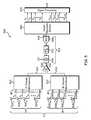
- FIG. 5is a high-level block diagram of a multi-antenna receiver system implemented in accordance with one embodiment of the present invention.
- FIG. 6is a flow chart illustrating steps carried out by the a multi-antenna receiver system of FIG. 5 to receive a signal with multiple antennas according to one embodiment
- FIG. 7is a block diagram of a multi-antenna receiver system configured to implement iterative multi-stage detection in accordance with one embodiment of the antenna system of FIG. 5 ;
- FIG. 8is a flowchart depicting steps carried out by the multi-antenna receiver system of FIG. 7 when carrying out the iterative multistage detection process according to one embodiment of the present invention
- FIG. 9is a graph depicting simulated results of the iterative multistage detection process carried out by the multi-antenna receiver system of FIG. 7 with a spreading factor of (N) selected to be 16 and a number of channels selected to be N+1;
- FIG. 10is a graph depicting simulated results of the iterative multistage detection process carried out by the multi-antenna receiver system of FIG. 7 with a spreading factor of (N) selected to be 16 and a number of channels selected to be N+2;
- FIG. 11is a graph depicting simulated results of the iterative multistage detection process carried out by the multi-antenna receiver system of FIG. 7 with a spreading factor of (N) selected to be 16 and a number of charnels selected to be N+3;
- FIG. 12is a graph depicting simulated results of the iterative multistage detection process carried out by the multi-antenna receiver system of FIG. 7 with a spreading factor of (N) selected to be 16 and a number of channels selected to be N+7; and
- FIG. 13is a graph depicting simulated results of the iterative multistage detection process carried out by the multi-antenna receiver system of FIG. 7 with a spreading factor of (N) selected to be 7 and a number of channels selected to be N+1.
- the present inventionallows K signal channels associated with K respective antenna elements to be orthogonally multiplexed onto a signal processing chain of a receiver using less than K orthogonal sequences.
- a receiver using a single receive chain characterized by a spreading factor of Nwhich would otherwise be limited to N antenna elements, may incorporate more than N antenna elements; thus increasing the capacity of the receiver.
- the present inventionis applicable to mobile devices and also infrastructure elements (e.g., base stations and access points).
- the present inventionis applicable to nearly all known wireless standards and modulation schemes (e.g., GSM, CDMA2000, WCDMA, WLAN, fixed wireless standards, OFDM and CDMA).
- GSMGlobal System for Mobile communications
- CDMA2000Code Division Multiple Access 2000
- WCDMAWideband Code Division Multiple Access 2000
- WLANWireless Local Area Network
- OFDMCode Division Multiple Access
- various advantages offered by the present inventionderive from the multiplexing of the signals received from a number of antenna elements onto a common receive chain processing path in order to reduce overall power consumption and cost.
- FIGS. 1-4In order to facilitate appreciation of the principles of the invention, a brief overview of various conventional multi-element antenna systems designed to mitigate delay spread, interference and fading effects is provided with reference to FIGS. 1-4 .
- FIG. 1shown is a block diagram of a conventional diversity receiver 100 in which the signals received by multiple antenna elements are weighted and combined in order to generate an output signal
- Shown in the conventional diversity receiver 100are a collection of M antenna elements 102 , and coupled with each respective antenna element are parallel receive chains 104 , 106 , 108 that include respective weighting portions 110 , 112 , 114 .
- the receive chains 104 , 106 , 108all couple with a combiner 116 disposed to produce a combined single 118 .
- An array of M antenna elementsgenerally provides an increased antenna gain of “M.” Such an array also provides a diversity gain against multipath fading dependent upon the correlation of the fading among the antenna elements.
- the antenna gainis defined as the reduction in required receive signal power for a given average output signal-to-noise ratio (SNR), while the diversity gain is defined as the reduction in the required average output SNR for a given bit error rate (BER) with fading.
- SNRaverage output signal-to-noise ratio
- BERbit error rate
- each of the M antenna elements 102are weighted at the respective weighting portions 110 , 112 , 114 and combined in the combiner 116 to maximize signal-to-interference-plus-noise ratio (SINR).
- SINRsignal-to-interference-plus-noise ratio
- FIG. 2a block diagram is shown of a conventional spatial-temporal (ST) filtering arrangement 200 . Shown are a first antenna 202 and a second antenna 204 respectively coupled to a first linear equalizer 206 and a second linear equalizer 208 . Outputs of each of the first and second linear equalizers 206 , 208 are coupled to a combiner 210 , and an output of the combiner 201 is coupled to an MLSE/DFE portion 212 .
- STspatial-temporal
- the filtering arrangement of FIG. 2is designed to eliminate delay spread using joint space-time processing.
- optimum space-time (ST) equalizerseither in the sense of a minimum mean square error (MMSE) or maximum signal-to-interference-plus-noise ratio (SINR), typically include a whitening filter.
- MMSEminimum mean square error
- SINRmaximum signal-to-interference-plus-noise ratio
- Llinear equalizers
- the linear equalizers (LE) 206 , 208are followed by a non-linear filter that is represented by the MLSE/DFE portion 212 , which is implemented using either a decision feedback equalizer (DFE) or maximum-likelihood sequence estimator (MLSE).
- DFEdecision feedback equalizer
- MLSEmaximum-likelihood sequence estimator
- turbo principlecan also be used to replace the non-linear filters with superior performance, but higher computational complexity.
- STPST processing
- SNR gains of up to 7 dB and SINR gains of up to 21 dBhave been reported with a modest number of antenna elements.
- FIG. 3shown is a generic representation of a multiple-input/multiple-output antenna arrangement within a wireless communication system 300 . Shown are a transmitter (TX) 302 coupled to multiple transmit antennas 304 , which are shown transmitting a signal via time varying obstructions 306 to multiple receive antennas 308 coupled to a receiver (RX) 310 .
- TXtransmitter
- RXreceiver
- MIMOmultiple-input/multiple-output antenna
- other antenna arrangementsmay be categorized, based upon the number of “inputs” and “outputs” to the channel linking a transmitter and receiver, as follows:
- MIMOsmulti-element antenna arrangements
- system capacity enhancementsthat can be achieved using these configurations. Assuming perfect estimates of the applicable channel at both the transmitter and receiver are available, in a MIMO system with M receive antennas the received signal decomposes to M independent channels. This results in an M-fold capacity increase relative to SISO systems. For a fixed overall transmitted power, the capacity offered by MIMOs scale with increasing SNR for a large, but practical, number of M of antenna elements.
- MIMO arrangementspermit capacity to be scaled by nearly M additional bits/cycle for each 3-dB increase in SNR.
- One technique which has been developed to utilize multiple antenna elements with a reduced number of signal processing chainsincludes multiplexing signals from multiple antennas on to a single processing chain as disclosed in a related copending U.S. application Ser. No. 10/606,371, entitled REDUCED-COMPLEXITY ANTENNA SYSTEM USING MULTIPLEXED RECEIVE CHAIN PROCESSING, filed Jun. 27, 2003, which is assigned to the assignee of the present application and is incorporated herein by reference in its entirety.
- the antenna processing system 400configured to reduce the number of separate signal processing chains associated with an antenna array in accordance with the above-identified U.S. application Ser. No. 10/606,371.
- the antenna processing system 400includes N antennas 402 , 404 , 406 , 408 coupled to a multiplexer 410 , which is coupled to a single signal processing chain 416 .
- the multiplexer 410is configured to orthogonally multiplex N channels (corresponding to the N antennas 402 onto the signal processing chain 416 , and is characterized by a spreading factor of N: that is, the multiplexer 410 utilizes N orthogonal sequences of length N.
- each of the N antennas 402receives an incident RF signal at spatially distinct locations and provides a replica of the incident RF signal to the multiplexer 410 .
- the multiplexer 410receives N replicas of the incident RF signal
- the multiplexer 410then orthogonally multiplexes the N replicas of the incident RF signal on to the single processing chain 416 to form a multiplexed signal comprising N multiplexed channels. Because each of the N channels is assigned a different orthogonal code during multiplexing, a manageable level of interference exists between the N multiplexed channels within the signal processing chain 416 .
- the multiplexed signalis then frequency downconverted, filtered and converted from analog form into a digital multiplexed signal.
- the digital multiplexed signalis then demultiplexed by a demultiplexor 436 into N separate signals that correspond to the N replicas of the signal received at the N antennas.
- the N separate signalsare then subjected to conventional spatial processing.
- the antenna processing system 400provides substantial cost and power savings over systems employing a separate signal processing chain for each antenna, in some applications it would be desirable if the antenna processing system 400 could support more than N channels, i.e., more than N antennas. Because each of the N orthogonal sequences is already used by one of the N antennas, however, an additional channel multiplexed onto the signal processing chain 416 would not be orthogonal to at least one of the N multiplexed channels. As a consequence, the additional channel would both impart deleterious interference on one or more of the N multiplexed channels and receive substantial interference from at least one of the N multiplexed channels.
- an antenna systemis configured to orthogonally multiplex K channels onto a single signal processing chain using N orthogonal sequences of length N.
- an iterative processis used to receive the multiplexed signal.
- interference from the first set of N channels imparted on the second set of M channelsis removed from the multiplexed signal, thereby enabling the symbol values associated with the second set of M channels to be reliably estimated.
- K channelsmay be multiplexed on to a single receiver chain with less than K orthogonal sequences, and then reliably estimated after processing (e.g., after down conversion and digitization) by the receiver chain.
- the antenna system 500includes an N channel multiplexer 502 , and an M channel multiplexer 507 .
- the N channel multiplexer 502is configured to receive N replicas of a signal with a set of N respective antennas 505
- the M channel multiplexer 507is configured to receive M replicas of the signal with a set of M respective antennas 508 .
- the N channel multiplexer 502 and the M channel multiplexer 507collectively multiplex, in cooperation with the summation module 530 , the K received signal replicas on to the signal processing chain 510 (Step 602 ).
- the N channel multiplexer 502assigns each of the N replicas of the signal a corresponding one of N orthogonal time sequences to form a first composite signal.
- the N channel multiplexer 502then overlays a common first PN scrambling sequence on to the first composite signal so as to form a first set of N scrambled signals 512 (also referred to herein as a “first set of N channels” or “set #1 channels”).
- the M channel multiplexer 507assigns each of M of the N orthogonal sequences to a corresponding one of the M replicas of the signal to form a second composite signal. In other words, the M channel multiplexer 507 reuses a subset of the N orthogonal sequences to form the second composite signal.
- the second multiplexer 507then overlays a second PN scrambling sequence on to the second composite signal so as to form a second set of M scrambled signals 514 (also referred to herein as a “second set of M channels” or “set #2 channels”).
- the summation module 530then combines the first set of N channels 512 and second set of M channels 514 so as to form a multiplexed signal 516 , which is provided to the signal processing chain 510 .
- the multiplexed signal 516is downconverted by a downconversion module 540 (e.g., a mixer to convert from RF to baseband frequency), filtered by a filter 542 and digitized by an analog to digital converter 544 .
- a downconversion module 540e.g., a mixer to convert from RF to baseband frequency
- the first set of N channelsonly experience interference as a consequence of the second set of M channels.
- the interference poweri.e., in-phase and quadrature phase energy
- the interference power associated with each channel of the second set of M channelsis 1/N. It follows that the total interference power experienced by the first set of N channels is M/N. As long as M remains relatively small compared to N it is possible to make at least preliminary decisions as to the values of the symbols transmitted via the first set of N channels.
- each channel of the second set of M channelsexperiences an interference power of N (1/N) or 1 as a consequence of the first set of N channels
- the symbol values associated with the second set of M channelsmay not be directly estimated with any reasonable degree of certainty through straightforward application of conventional techniques.
- the resultant baseband multiplexed signal 546is provided to a signal recovery module 550 .
- the signal recovery module 550receives the baseband multiplexed signal 546 and recovers K separate signals, which correspond to the K received signal replicas received by the K antennas.
- the signal recovery module 550receives the baseband multiplexed signal 546 , and removes interference imparted by the first set of N channels on the second set of M channels from the multiplexed signal so as to generate a preliminary estimate of the symbol streams carried by the second set of M channels (Step 604 ).
- the signal recovery module 550determines the interference imparted by the first set of N channels upon the second set of M channels by demultiplexing the first set of N channels from the baseband multiplexed signal 546 , establishing preliminary values of the symbols received through the first set of N channels and then synthesizing an aggregate interference signal associated with the first set of N channels based upon these preliminary symbol values.
- the aggregate interference signalalso provides an estimate of the symbol streams conveyed via the first set of N channels.
- the signal recovery module 550demultiplexes M separate signals (corresponding to the M replicas of the signal) from the preliminary estimate of the second set of M channels (Step 606 ). Because interference from the first set of N channels is first removed from the baseband multiplexed signal 546 to form the preliminary estimate of the second set of M channels, the signal recovery module 550 may reliably estimate the symbol values associated with the M separate signals.
- interference from the second set of M channelsis then removed from the estimates of the symbol streams corresponding to the first set of N channels (produced during Step 604 ) in order to provide a revised estimate of these symbol streams (Step 608 ). Since the preliminary symbol values of the first set of N channels are initially made in the presence of the interference from the second set of M channels, this step removes the interference originating from the second set of M channels so the symbol values of the first set of N channels maybe more reliably estimated.
- the signal recovery module 550then demultiplexes the revised estimate of the first set of N channels into N separate signals (corresponding to the N replicas of the incident RF signal) from the baseband multiplexed signal 546 (Step 610 ).
- the signal recovery module 550then provides K separate signals (i.e., the N separate signals and the M separate signals) to a signal processing portion 570 for further processing.
- the signal processing portion 570may include additional spatial and iterative (turbo) processing, as well as de-interleaving (bit and/or symbol level) and channel decoding.
- the receiver system 700includes a multistage receiver unit 710 disposed to receive and process RF signal energy collected by a K element antenna array 712 . As shown, the receiver system also includes a signal recovery module 714 , which functions to separate K multiplexed channels. In this way, K symbol streams received at the K element antenna array 712 , and conveyed by the K multiplexed channels, may be separated and recovered at the signal recovery module 714 .
- the signal recovery portion 714includes an N channel recovery portion 716 and an M channel recovery portion 718 , which cooperate to carry out the functions of the signal recovery module 714 .
- the N channel recovery portion 716in cooperation with the M channel recovery portion 718 function to provide N separate symbol streams and M separate symbol streams, respectively.
- the N separate symbol streams and the M separate symbol streamsprovide K separate symbol streams that correspond to (e.g., closely estimate) the K symbol streams received at the K element antenna array 712 .
- the antenna array 712includes a first set of N spatially-separated receiving antennas 704 and a second set of M spatially-separated receiving antennas 708 .
- the N antennas 704 and the M antennas 708couple an RF signal comprised of a first set of N channels and a second set of M channels into the receiver unit 710 .
- the received RF signalis passed through the N antennas 704 to a set #1 channel spreading module 720 and is passed through the M antennas 708 to a channel set #2 spreading module 727 .
- the N received signal replicas a 1 , a 2 , . . . a N received from the N antenna elements 704 1 , 704 2 , and 704 Nare each spread by a different one of N orthogonal sequences of length N associated with the first set of N channels.
- the M received signal replicas a N+1 , a N+2 , . . . a N+M received from the M antenna elements 70 N+1 , 708 N+2 , . . . 708 N+Mare each spread by a different one of M orthogonal sequences of length N associated with the second set of M channels.
- a set of N spread signals 730are provided by the spreading module 720 to a summation module 731 operative to provide a composite set #1 channel signal to a first mixer element 732 .
- a set of M spread signals 737are provided by the spreading module 727 to a summation module 736 operative to provide a composite set #2 channel signal to a second mixer element 740 .
- the composite set #1 channel signalis scrambled at the first mixer element 732 using a first PN scrambling sequence P 1 and the composite channel set #2 signal is scrambled at the second mixer element 740 using a second PN scrambling sequence P 2 .
- the resultant set #1 channel and set #2 channel scrambled signals(also referred to herein as a first set of N channel signals and a second set of M channel signals, respectively) are combined within a summation module 744 in order to form a multiplexed signal 745 which includes the first set of N channel signals and a second set of M channel signals.
- the multiplexed signal 745is filtered, down-converted from RF, and digitized to reform the multiplexed signal 745 as a baseband multiplexed signal 746 composed from received samples at baseband frequencies.
- the baseband multiplexed signal 746 output of the RF processing module 778is provided to a buffer 749 in the signal recover module 714 , and the buffer 749 is switchably coupled to a baseband mixer element 752 via a switch 750 .
- the complex conjugate P 1 * of the first PN scrambling sequence P 1is also applied to the baseband mixer element 752 which, in cooperation with a set #1 channel despreading module 756 , serves to despread the received first set of N channel signals.
- the complex conjugates of each of the N orthogonal time sequencesare each used to complete the despreading of the N baseband signal streams 760 received from the baseband mixer element 752 . That is, each of the N baseband signals is despread by one of the N orthogonal time sequences.
- the despreading module 756includes a bank of N complex correlators which are matched to the N channels in the first set of N channels.
- the set of N despread baseband signals from the despreading module 756are then passed through a corresponding set of N threshold detectors 767 , which yields an initial estimate of the current symbol values for each of the received first set of N channel signals (i.e., â 1 , â 2 , . . . , â N ).
- the estimated symbol values a â 1 , â 2 , . . . , â N for the first set of N channel signalsare used to synthesize an interference signal intended to replicate the baseband signal waveform of the received first set of N channel signals.
- the estimated symbol values â 1 , â 2 , . . . , â N of first set of N channel signalsare processed by a re-spreading module 768 operative to spread each such value using the applicable one of the N orthogonal time sequences.
- the resultant re-spread set of N channel signalsare then combined within a summation module 772 in order to produce a composite re-spread signal.
- the composite re-spread signalis scrambled within mixer element 776 using the first PN sequence P 1 , thereby yielding a regenerated set of N channel signals 777 , which is provided as an interference signal 780 to a difference element 782 in the M channel recovery portion 718 .
- the regenerated set of N channel signals 777is also provided to an adder element 798 for use during a second iteration.
- the difference element 782is arranged to receive the interference signal 780 for the first set of N channels and the baseband multiplexed signal 746 from the delay element 787 .
- the output of difference element 782which approximates the baseband signal waveform of the second set of M channel signals, is descrambled by mixer element 786 using the complex conjugate P 2 * of the second PN sequence P 2 .
- the resultant descrambled signalis then despread within the despreading module 788 by each of the M orthogonal time sequences associated with the second set of M channels.
- the despreading module 788includes a bank of M complex correlators which are matched to the M channels in the first set of M channels.
- the resulting set of M despread baseband signals from the despreading module 788are applied to a set of M threshold detectors 790 , which yield estimates of current symbol values â N+1 , â N+2 , . . . , â N+M for each of the second set of M channel signals.
- the estimated symbol values â N+1 , â N+2 , . . . , â N+M of the second set of M channel signalsare processed by a second respreading module 792 operative to spread each such value using the applicable one of the M orthogonal time sequences (i.e., the subset of the N orthogonal sequences used by the channel set #2 spreading module 727 ).
- the resultant re-spread set of M channel signalsare then combined within a summation module 794 in order to produce a second composite re-spread signal.
- the second composite re-spread signalis scrambled within mixer element 796 using the second PN sequence P 2 , thereby yielding a regenerated set of M channel signals 797 , which is provided to an adder element 798 .
- K separate estimated symbol valuesi.e., the estimated symbol values â 1 , â 2 , . . . , â N of first set of N channel signals and the estimated symbol values â N+1 , â N+2 , . . . , â N+M of the second set of M channel signals, are provided during a first iteration.
- the adder element 798combines the regenerated set of N channel signals 777 and the regenerated set of M channel signals 797 to form a regenerated baseband multiplexed signal 799 , which according to an exemplary embodiment, is processed during a second iteration as discussed herein to produce a more accurate set of K separate symbol values.
- the iterative interference removal processwill be better understood with a brief consideration of the effect of spreading and scrambling the N and M signal replicas received at the N antennas 505 and the M antennas 508 , respectively.
- each of the sequences W iis independent of the symbol index, since each sequence repeats from one symbol to the next.
- the symbol indexmay also be removed from the PN sequences since the signal processing of concern is memoryless. That is, detection of a current symbol does not involve signal samples from previous and future symbols. Consequently, each of the PN sequences may be expressed as P n (p n,1 , p n,2 , . . .
- complex-valued PN sequencesare considered; that is, the chips p n,m randomly assume values from the set ⁇ exp(j ⁇ /2), exp( ⁇ j ⁇ /2), exp(j3 ⁇ /2), exp( ⁇ j3 ⁇ /2) ⁇ .
- FIG. 8shown is a flowchart depicting steps carried out by the multi-antenna receiver system 700 when carrying out the iterative multistage detection process according to one embodiment of the present invention.
- initial estimates of the symbol values of the first set of N channel signalsmay be made using a threshold detector immediately following despreading by the corresponding composite chip sequences (Step 802 ). This step of the detection process yields the following set of set of initial decisions for the first set of N channel signals: â 1 , â 2 , . . . , â N .
- the initial decisions â 1 , â 2 , . . . , â Nare then used to synthesize an estimated interference caused by the first set of N channels with respect to the second set of M channels (Step 804 ).
- This estimated interferenceis then subtracted from the baseband signal energy of the multiplexed signal (Step 806 ), thereby yielding a difference signal corresponding to an estimate of the second set of M channel signals (at baseband).
- the total interference from the first set of N channelsmay be expressed as:
- I N+kcan be estimated once the symbol decisions corresponding to channels 1 to N of the first set of N channels have been made. This estimate I N+k is subtracted from the corresponding signal at a correlator output before sending the result to a threshold detector.
- the symbol values of the received second set of M channel signalsare estimated using the threshold detector 790 immediately following despreading by the despreading module 788 (Step 808 ). This step of the detection process yields the following set of symbol decisions for the second set of M channel signals: â N+1 , â N+2 , . . . , â N+M .
- Step 802If all initial decisions â 1 , â 2 , . . . , â N for the first set of N channel signals are made correctly at Step 802 , complete interference cancellation effectively occurs at Step 806 and substantially no mutual interference between the first set of N channels and the second set of M channels will remain when the symbol values of the second set of M channel signals are estimated at Step 808 .
- Each incorrect decision with regard to â 1 , â 2 , . . . , â N yielded in Step 802will, however, cause the corresponding term in I N+k to increase and thereby reduce the likelihood of accurate estimation of the second set of M channels.
- a second iteration ofmay be performed. Specifically, the symbol decisions â N+1 , â N+2 , . . . , â N+M made for the second set of M channels in the first iteration are used to synthesize interference of the second set of M channel signals (Step 810 ). The interference of the second set of M channels is then subtracted from the first set of N channel signals (Step 812 ).
- the baseband multiplexed signal 746 produced by the RF processing module 778is buffered within buffer 749 and directly coupled therefrom to the mixer element 752 via switch 750 .
- the switch 750is set to couple the regenerated baseband multiplexed signal 799 from the output of adder element 798 (obtained from mixer elements 776 and 796 ) to the baseband mixer element 752 , while the while the buffer 749 is filled with the incoming signal received from RF processing module 778 .
- all iterationsare performed while the buffer 749 is updated and completed before the buffer contents has been filled with a new RF signal.
- the iterative processingis done within one bit interval (i.e., within one bit duration), so that the size of the buffer 749 remains manageable.
- the iterative processingis performed in a much shorter period than a bit duration, and when the buffer 749 is filled with a new set of bit samples, the processing of the new set of bit samples by the signal recovery module 714 begins.
- the regenerated baseband multiplexed signal 799is descrambled and despread by the baseband mixer element 752 and the set #1 channel despreading module 756 to provide N despread baseband signals.
- the synthesized interference due to the second set of M channel signals (determined during the first iteration) from Step 810is then subtracted from the k th signal of the set of N despread baseband signals at the output of the despreading module 756 ; thus effectively subtracting the interference of the second set of M channels from the first set of N channel signals (Step 812 ).
- the N interferenced-reduced signals produced by subtracting the synthesized interference from the k th signal of the set of N despread baseband signalsis passed to the applicable threshold detector 767 . This process is repeated for all of the first set of N channels to determine a revised set of N symbol values of the first set of N channel signals (Step 814 ).
- a revised estimate of the interference caused by the first set of N channels with respect to the second set of M channelsis then determined based upon the a revised set of symbol values (Step 816 ).
- the revised symbol values of the first set of N channel signalsare respread by the re-spreading module 768 , recombined within the summation module 772 and scrambled within mixer element 776 using the first PN sequence P 1 , thereby producing another interference signal 780 , which is subtracted from the regenerated baseband multiplexed signal at the difference element 782 so as to generate a difference signal corresponding to an estimate of the second set of M channel signals (Step 816 ).
- Symbol value decisions for the second set of M channelsare then made during the second iteration following subtraction of the interference of the first set of N channels (Step 818 ).
- the total interference experienced by the k th channel of the second set of M channelsi.e., channel N+k
- Equation (1)the output of the despreading module 788 for the k th channel of the second set of M channels is sent to the corresponding set of M threshold detectors 790 , which produces a revised set of M symbol values of the first set of M channel signals.
- a revised set of N symbol values of the first set of N channel signals and a revised set of M symbol values of the second set of M channel signalsis provided by the signal recovery portion 714 .
- revised symbol valuesprovide K separate symbol values, which correspond to K symbol streams in the K received signal replicas received at the K element antenna array 712 .
- FIGS. 9-13depict the results of various simulations of the above-described iterative multi-stage detection process using two sets of orthogonal spreading sequences.
- a spreading factor N of 16was employed, while in FIG. 13 a spreading factor N of 7 was utilized.
- the number of “excess” channels Mwas selected to be 1, 2, 3 and 7 in FIGS. 9-12 , respectively, and M was chosen to be 1 in the case of FIG. 13 .
- the simulationswere executed exclusively at baseband (no modulation or spectrum-shaping filtering were simulated), and an AWGN channel and synchronous operation (i.e., synchronous time spread) were assumed.
- trace Arepresents the theoretical single user bound while trace B represents the performance of a single, uncoded channel (i.e., as “single user bound”) obtained through simulation.
- trace Crepresents the BER of the first set of N channels prior to the performance of interference cancellation
- trace Drepresents the BER of the second set of M channels prior to interference cancellation
- trace Eillustrates the overall BER (i.e., both the first set of N and the second set of M channels) prior to interference cancellation.
- the BER of the first set of N channels following the first iteration of interference cancellationis represented by trace F
- the BER of the second set of M channels following the first iteration of interference cancellationis represented by trace G
- the overall BER following the first iteration of interference cancellationis illustrated by trace H.
- the BER of the first set of N channels following the second iteration of interference cancellationis represented by trace I
- the BER of the second set of M channels following the second iteration of interference. cancellationis represented by trace J
- the overall BER following the second iteration of interference cancellationis illustrated by trace K.
- FIGS. 9-13demonstrate the effectiveness of certain embodiments the inventive iterative multi-stage detection technique
- a value N of 16(which results in deployment of at least 16 antennas) may be impractical in certain applications.
- interference due to the second set of M channel signals from the first set of N channel signalsmay be removed at the chip level using a difference element as was done to remove the interference due to the first set of N channels from the second set of M channel signals using the difference element 782 .
- interference due to the first set of N channel signalswas removed from the second set of M channel signals at the chip level using the difference element 782 .
- interference due to the first set of N channel signalsmay be removed from the second set of M channel signals on the symbol level at a correlator output after the despreading module 788 .
- interference from either the first set of N channels or the second set of M channelsmay be removed at either the chip or the symbol level and still be well within the scope of the present invention.
Landscapes
- Engineering & Computer Science (AREA)
- Computer Networks & Wireless Communication (AREA)
- Signal Processing (AREA)
- Power Engineering (AREA)
- Radio Transmission System (AREA)
Abstract
Description
- Single-input/single-output (SISO) systems, which include transceivers (e.g., mobile units and a base station) with a single antenna for uplink and down link communications.
- Multi-input/single-output (MISO) systems, which include one or more receivers, which downlink via multiple antenna inputs, and one or more transmitters, which uplink via a single antenna output.
- Single-input/multi-output (SIMO) systems, which include one or more receivers, which downlink via a single antenna input, and one or more transmitters, which uplink via multiple antenna outputs.
where αiis the data symbol of the ithchannel during the current symbol interval. Each term in the outer sum in (1) represents the interference from one of the N channels. Since the chip sequences (αi,1, αi,2, . . . , αi,N) and (βi,1, βi,2, . . . , βi,N) are known to the receiver, IN+kcan be estimated once the symbol decisions corresponding to
This interference is synthesized by substituting âN+1for aN+1in Equation (2) above for i=1,2, . . . ,M . Since âN+1=aN+1with a probability close to 1, the synthesized replica will generally be virtually identical to the actual interference.
Claims (57)
Priority Applications (2)
| Application Number | Priority Date | Filing Date | Title |
|---|---|---|---|
| US12/246,935US8027650B2 (en) | 2002-08-28 | 2008-10-07 | Iterative multi-stage detection technique for a diversity receiver having multiple antenna elements |
| US13/109,101US20110217942A1 (en) | 2002-08-28 | 2011-05-17 | Iterative multi-stage detection technique for a diversity receiver having multiple antenna elements |
Applications Claiming Priority (4)
| Application Number | Priority Date | Filing Date | Title |
|---|---|---|---|
| US40752402P | 2002-08-28 | 2002-08-28 | |
| US10/650,478US7215934B2 (en) | 2002-08-28 | 2003-08-28 | Iterative multi-stage detection technique for a diversity receiver having multiple antenna elements |
| US11/695,394US7433660B2 (en) | 2002-08-28 | 2007-04-02 | Iterative multi-stage detection technique for a diversity receiver having multiple antenna elements |
| US12/246,935US8027650B2 (en) | 2002-08-28 | 2008-10-07 | Iterative multi-stage detection technique for a diversity receiver having multiple antenna elements |
Related Parent Applications (1)
| Application Number | Title | Priority Date | Filing Date |
|---|---|---|---|
| US11/695,394ContinuationUS7433660B2 (en) | 2002-08-28 | 2007-04-02 | Iterative multi-stage detection technique for a diversity receiver having multiple antenna elements |
Related Child Applications (1)
| Application Number | Title | Priority Date | Filing Date |
|---|---|---|---|
| US13/109,101ContinuationUS20110217942A1 (en) | 2002-08-28 | 2011-05-17 | Iterative multi-stage detection technique for a diversity receiver having multiple antenna elements |
Publications (2)
| Publication Number | Publication Date |
|---|---|
| US20090111404A1 US20090111404A1 (en) | 2009-04-30 |
| US8027650B2true US8027650B2 (en) | 2011-09-27 |
Family
ID=31978498
Family Applications (10)
| Application Number | Title | Priority Date | Filing Date |
|---|---|---|---|
| US10/650,478Expired - LifetimeUS7215934B2 (en) | 2002-08-28 | 2003-08-28 | Iterative multi-stage detection technique for a diversity receiver having multiple antenna elements |
| US11/691,813Expired - Fee RelatedUS7822395B2 (en) | 2002-08-28 | 2007-03-27 | Iterative multi-stage detection technique for a diversity receiver having multiple antenna elements |
| US11/695,375Expired - Fee RelatedUS7433659B2 (en) | 2002-08-28 | 2007-04-02 | Iterative multi-stage detection technique for a diversity receiver having multiple antenna elements |
| US11/695,394Expired - Fee RelatedUS7433660B2 (en) | 2002-08-28 | 2007-04-02 | Iterative multi-stage detection technique for a diversity receiver having multiple antenna elements |
| US11/695,384Expired - LifetimeUS7412218B2 (en) | 2002-08-28 | 2007-04-02 | Iterative multi-stage detection technique for a diversity receiver having multiple antenna elements |
| US11/695,325Expired - Fee RelatedUS7392025B2 (en) | 2002-08-28 | 2007-04-02 | Iterative multi-stage detection technique for a diversity receiver having multiple antenna elements |
| US12/246,887Expired - Fee RelatedUS7917108B2 (en) | 2002-08-28 | 2008-10-07 | Iterative multi-stage detection technique for a diversity receiver having multiple antenna elements |
| US12/246,935Expired - Fee RelatedUS8027650B2 (en) | 2002-08-28 | 2008-10-07 | Iterative multi-stage detection technique for a diversity receiver having multiple antenna elements |
| US13/074,132AbandonedUS20110211508A1 (en) | 2002-08-28 | 2011-03-29 | Iterative multi-stage detection technique for a diversity receiver having multiple antenna elements |
| US13/109,101AbandonedUS20110217942A1 (en) | 2002-08-28 | 2011-05-17 | Iterative multi-stage detection technique for a diversity receiver having multiple antenna elements |
Family Applications Before (7)
| Application Number | Title | Priority Date | Filing Date |
|---|---|---|---|
| US10/650,478Expired - LifetimeUS7215934B2 (en) | 2002-08-28 | 2003-08-28 | Iterative multi-stage detection technique for a diversity receiver having multiple antenna elements |
| US11/691,813Expired - Fee RelatedUS7822395B2 (en) | 2002-08-28 | 2007-03-27 | Iterative multi-stage detection technique for a diversity receiver having multiple antenna elements |
| US11/695,375Expired - Fee RelatedUS7433659B2 (en) | 2002-08-28 | 2007-04-02 | Iterative multi-stage detection technique for a diversity receiver having multiple antenna elements |
| US11/695,394Expired - Fee RelatedUS7433660B2 (en) | 2002-08-28 | 2007-04-02 | Iterative multi-stage detection technique for a diversity receiver having multiple antenna elements |
| US11/695,384Expired - LifetimeUS7412218B2 (en) | 2002-08-28 | 2007-04-02 | Iterative multi-stage detection technique for a diversity receiver having multiple antenna elements |
| US11/695,325Expired - Fee RelatedUS7392025B2 (en) | 2002-08-28 | 2007-04-02 | Iterative multi-stage detection technique for a diversity receiver having multiple antenna elements |
| US12/246,887Expired - Fee RelatedUS7917108B2 (en) | 2002-08-28 | 2008-10-07 | Iterative multi-stage detection technique for a diversity receiver having multiple antenna elements |
Family Applications After (2)
| Application Number | Title | Priority Date | Filing Date |
|---|---|---|---|
| US13/074,132AbandonedUS20110211508A1 (en) | 2002-08-28 | 2011-03-29 | Iterative multi-stage detection technique for a diversity receiver having multiple antenna elements |
| US13/109,101AbandonedUS20110217942A1 (en) | 2002-08-28 | 2011-05-17 | Iterative multi-stage detection technique for a diversity receiver having multiple antenna elements |
Country Status (5)
| Country | Link |
|---|---|
| US (10) | US7215934B2 (en) |
| EP (1) | EP1537622B1 (en) |
| CN (1) | CN100542059C (en) |
| AU (1) | AU2003268227A1 (en) |
| WO (1) | WO2004021506A2 (en) |
Families Citing this family (96)
| Publication number | Priority date | Publication date | Assignee | Title |
|---|---|---|---|---|
| US7391819B1 (en)* | 2002-10-08 | 2008-06-24 | Urbain Alfred von der Embse | Capacity bound and modulation for communications |
| CN100542059C (en)* | 2002-08-28 | 2009-09-16 | 美国博通公司 | Method and device for receiving signals |
| US7715508B2 (en)* | 2005-11-15 | 2010-05-11 | Tensorcomm, Incorporated | Iterative interference cancellation using mixed feedback weights and stabilizing step sizes |
| US8121020B1 (en)* | 2002-10-08 | 2012-02-21 | Urbain A. von der Embse | QLM demodulation |
| US7577403B1 (en)* | 2003-10-06 | 2009-08-18 | Rilling Kenneth F | Non-capture one-tuner smart antenna |
| US7437135B2 (en) | 2003-10-30 | 2008-10-14 | Interdigital Technology Corporation | Joint channel equalizer interference canceller advanced receiver |
| US7400692B2 (en) | 2004-01-14 | 2008-07-15 | Interdigital Technology Corporation | Telescoping window based equalization |
| US8213553B2 (en)* | 2004-04-12 | 2012-07-03 | The Directv Group, Inc. | Method and apparatus for identifying co-channel interference |
| US7672285B2 (en)* | 2004-06-28 | 2010-03-02 | Dtvg Licensing, Inc. | Method and apparatus for minimizing co-channel interference by scrambling |
| KR100862511B1 (en)* | 2004-04-12 | 2008-10-08 | 더 디렉티브 그룹, 인크. | A method for minimizing co-channel interference in a communication system and in a satellite based communication system |
| US7161988B2 (en)* | 2004-04-12 | 2007-01-09 | The Directv Group, Inc. | Method and apparatus for minimizing co-channel interference |
| JP2005311797A (en)* | 2004-04-22 | 2005-11-04 | Tektronix Japan Ltd | Despreading method |
| EP1603264B1 (en)* | 2004-06-04 | 2013-02-27 | France Télécom | Method and system for receiving a linearly precoded and channel coded signal |
| FR2873877B1 (en)* | 2004-08-02 | 2006-12-01 | Wavecom Sa | METHOD FOR DESIGNING A DIGITAL RECEPTION FILTER AND CORRESPONDING RECEPTION DEVICE |
| SE0402003D0 (en)* | 2004-08-06 | 2004-08-06 | Ericsson Telefon Ab L M | Method and system of radio communications |
| JP4841615B2 (en) | 2005-03-14 | 2011-12-21 | テルコーディア ライセンシング カンパニー, リミテッド ライアビリティ カンパニー | Repetitive MIMO receiver using group-wise demapping |
| US7991088B2 (en) | 2005-11-15 | 2011-08-02 | Tommy Guess | Iterative interference cancellation using mixed feedback weights and stabilizing step sizes |
| US7711075B2 (en)* | 2005-11-15 | 2010-05-04 | Tensorcomm Incorporated | Iterative interference cancellation using mixed feedback weights and stabilizing step sizes |
| US7826516B2 (en) | 2005-11-15 | 2010-11-02 | Rambus Inc. | Iterative interference canceller for wireless multiple-access systems with multiple receive antennas |
| WO2007025121A1 (en)* | 2005-08-26 | 2007-03-01 | The Directv Group, Inc. | Method and apparatus for determining scrambling codes for signal transmission |
| US20070110135A1 (en)* | 2005-11-15 | 2007-05-17 | Tommy Guess | Iterative interference cancellation for MIMO-OFDM receivers |
| US7623602B2 (en)* | 2005-11-15 | 2009-11-24 | Tensorcomm, Inc. | Iterative interference canceller for wireless multiple-access systems employing closed loop transmit diversity |
| US8130726B2 (en)* | 2005-12-20 | 2012-03-06 | Qualcomm Incorporated | Coarse bin frequency synchronization in a communication system |
| CN101064541B (en)* | 2006-04-25 | 2010-06-09 | 上海无线通信研究中心 | Parallel belief propagation detection method of multi-antenna system |
| CN101714885B (en)* | 2006-04-25 | 2013-04-10 | 上海无线通信研究中心 | Serial belief propagation detection method of multi-antenna system |
| JP3930037B1 (en)* | 2006-04-27 | 2007-06-13 | 株式会社アドバンテスト | Test apparatus and test method |
| US20080084951A1 (en)* | 2006-10-06 | 2008-04-10 | Helen Chen | Systems and methods for receiving multiple input, multiple output signals for test and analysis of multiple-input, multiple-output systems |
| US8873585B2 (en) | 2006-12-19 | 2014-10-28 | Corning Optical Communications Wireless Ltd | Distributed antenna system for MIMO technologies |
| CN101018074B (en)* | 2007-03-08 | 2010-12-08 | 中兴通讯股份有限公司 | A receiver and receiving method |
| US20100054746A1 (en) | 2007-07-24 | 2010-03-04 | Eric Raymond Logan | Multi-port accumulator for radio-over-fiber (RoF) wireless picocellular systems |
| US8175459B2 (en) | 2007-10-12 | 2012-05-08 | Corning Cable Systems Llc | Hybrid wireless/wired RoF transponder and hybrid RoF communication system using same |
| WO2009081376A2 (en) | 2007-12-20 | 2009-07-02 | Mobileaccess Networks Ltd. | Extending outdoor location based services and applications into enclosed areas |
| EP2329605A4 (en)* | 2008-09-22 | 2013-04-17 | Nortel Networks Ltd | Method and system for space code transmit diversity of pucch |
| US9673904B2 (en) | 2009-02-03 | 2017-06-06 | Corning Optical Communications LLC | Optical fiber-based distributed antenna systems, components, and related methods for calibration thereof |
| AU2010210766A1 (en) | 2009-02-03 | 2011-09-15 | Corning Cable Systems Llc | Optical fiber-based distributed antenna systems, components, and related methods for monitoring and configuring thereof |
| AU2010210771B2 (en) | 2009-02-03 | 2015-09-17 | Corning Cable Systems Llc | Optical fiber-based distributed antenna systems, components, and related methods for calibration thereof |
| US8599803B1 (en) | 2009-05-01 | 2013-12-03 | Marvell International Ltd. | Open loop multiple access for WLAN |
| US9590733B2 (en) | 2009-07-24 | 2017-03-07 | Corning Optical Communications LLC | Location tracking using fiber optic array cables and related systems and methods |
| US8280259B2 (en) | 2009-11-13 | 2012-10-02 | Corning Cable Systems Llc | Radio-over-fiber (RoF) system for protocol-independent wired and/or wireless communication |
| US8275265B2 (en) | 2010-02-15 | 2012-09-25 | Corning Cable Systems Llc | Dynamic cell bonding (DCB) for radio-over-fiber (RoF)-based networks and communication systems and related methods |
| EP2553839A1 (en) | 2010-03-31 | 2013-02-06 | Corning Cable Systems LLC | Localization services in optical fiber-based distributed communications components and systems, and related methods |
| US8570914B2 (en) | 2010-08-09 | 2013-10-29 | Corning Cable Systems Llc | Apparatuses, systems, and methods for determining location of a mobile device(s) in a distributed antenna system(s) |
| US9252874B2 (en) | 2010-10-13 | 2016-02-02 | Ccs Technology, Inc | Power management for remote antenna units in distributed antenna systems |
| US9160449B2 (en) | 2010-10-13 | 2015-10-13 | Ccs Technology, Inc. | Local power management for remote antenna units in distributed antenna systems |
| CN103314556B (en) | 2010-11-24 | 2017-09-08 | 康宁光缆系统有限责任公司 | For distributing antenna system can be with the Power entry module and associate power unit, component and method for electrically connecting and/or disconnecting |
| US11296504B2 (en) | 2010-11-24 | 2022-04-05 | Corning Optical Communications LLC | Power distribution module(s) capable of hot connection and/or disconnection for wireless communication systems, and related power units, components, and methods |
| US8576947B2 (en)* | 2011-04-19 | 2013-11-05 | Litepoint Corporation | System and method for simultaneous MIMO signal testing with single vector signal analyzer |
| EP2702780A4 (en) | 2011-04-29 | 2014-11-12 | Corning Cable Sys Llc | Systems, methods, and devices for increasing radio frequency (rf) power in distributed antenna systems |
| CN103548290B (en) | 2011-04-29 | 2016-08-31 | 康宁光缆系统有限责任公司 | Judge the communication propagation delays in distributing antenna system and associated component, System and method for |
| US8891464B2 (en) | 2011-09-19 | 2014-11-18 | Redline Innovations Group, Inc. | Architecture, devices and methods for supporting multiple channels in a wireless system |
| EP2832012A1 (en) | 2012-03-30 | 2015-02-04 | Corning Optical Communications LLC | Reducing location-dependent interference in distributed antenna systems operating in multiple-input, multiple-output (mimo) configuration, and related components, systems, and methods |
| US9781553B2 (en) | 2012-04-24 | 2017-10-03 | Corning Optical Communications LLC | Location based services in a distributed communication system, and related components and methods |
| WO2013162988A1 (en) | 2012-04-25 | 2013-10-31 | Corning Cable Systems Llc | Distributed antenna system architectures |
| US9154222B2 (en) | 2012-07-31 | 2015-10-06 | Corning Optical Communications LLC | Cooling system control in distributed antenna systems |
| WO2014024192A1 (en) | 2012-08-07 | 2014-02-13 | Corning Mobile Access Ltd. | Distribution of time-division multiplexed (tdm) management services in a distributed antenna system, and related components, systems, and methods |
| US9455784B2 (en) | 2012-10-31 | 2016-09-27 | Corning Optical Communications Wireless Ltd | Deployable wireless infrastructures and methods of deploying wireless infrastructures |
| WO2014074832A1 (en)* | 2012-11-09 | 2014-05-15 | Interdigital Patent Holdings, Inc. | Method and apparatus for coordinated orthogonal channel access (coca) |
| US10257056B2 (en) | 2012-11-28 | 2019-04-09 | Corning Optical Communications LLC | Power management for distributed communication systems, and related components, systems, and methods |
| EP2926466A1 (en) | 2012-11-29 | 2015-10-07 | Corning Optical Communications LLC | HYBRID INTRA-CELL / INTER-CELL REMOTE UNIT ANTENNA BONDING IN MULTIPLE-INPUT, MULTIPLE-OUTPUT (MIMO) DISTRIBUTED ANTENNA SYSTEMS (DASs) |
| US9647758B2 (en) | 2012-11-30 | 2017-05-09 | Corning Optical Communications Wireless Ltd | Cabling connectivity monitoring and verification |
| US9158864B2 (en) | 2012-12-21 | 2015-10-13 | Corning Optical Communications Wireless Ltd | Systems, methods, and devices for documenting a location of installed equipment |
| US9497706B2 (en) | 2013-02-20 | 2016-11-15 | Corning Optical Communications Wireless Ltd | Power management in distributed antenna systems (DASs), and related components, systems, and methods |
| US8917786B1 (en)* | 2013-05-09 | 2014-12-23 | Urbain Alfred von der Embse | QLM communications faster than Shannon rate |
| WO2014199380A1 (en) | 2013-06-12 | 2014-12-18 | Corning Optical Communications Wireless, Ltd. | Time-division duplexing (tdd) in distributed communications systems, including distributed antenna systems (dass) |
| EP3008515A1 (en) | 2013-06-12 | 2016-04-20 | Corning Optical Communications Wireless, Ltd | Voltage controlled optical directional coupler |
| IL226992A (en) | 2013-06-17 | 2017-11-30 | Elta Systems Ltd | System and method for receiving and processing array antenna signals |
| US9247543B2 (en) | 2013-07-23 | 2016-01-26 | Corning Optical Communications Wireless Ltd | Monitoring non-supported wireless spectrum within coverage areas of distributed antenna systems (DASs) |
| US9661781B2 (en) | 2013-07-31 | 2017-05-23 | Corning Optical Communications Wireless Ltd | Remote units for distributed communication systems and related installation methods and apparatuses |
| WO2015029028A1 (en) | 2013-08-28 | 2015-03-05 | Corning Optical Communications Wireless Ltd. | Power management for distributed communication systems, and related components, systems, and methods |
| US9385810B2 (en) | 2013-09-30 | 2016-07-05 | Corning Optical Communications Wireless Ltd | Connection mapping in distributed communication systems |
| EP2869476A1 (en)* | 2013-10-29 | 2015-05-06 | Alcatel Lucent | Transmitter Method For Multiple Antenna Systems, Transmitter Apparatus And Network Node Thereof |
| WO2015079435A1 (en) | 2013-11-26 | 2015-06-04 | Corning Optical Communications Wireless Ltd. | Selective activation of communications services on power-up of a remote unit(s) in a distributed antenna system (das) based on power consumption |
| US9178635B2 (en) | 2014-01-03 | 2015-11-03 | Corning Optical Communications Wireless Ltd | Separation of communication signal sub-bands in distributed antenna systems (DASs) to reduce interference |
| US9628163B2 (en)* | 2014-03-25 | 2017-04-18 | Marvell International Ltd. | Low-complexity communication terminal with enhanced receive diversity |
| US9775123B2 (en) | 2014-03-28 | 2017-09-26 | Corning Optical Communications Wireless Ltd. | Individualized gain control of uplink paths in remote units in a distributed antenna system (DAS) based on individual remote unit contribution to combined uplink power |
| US9357551B2 (en) | 2014-05-30 | 2016-05-31 | Corning Optical Communications Wireless Ltd | Systems and methods for simultaneous sampling of serial digital data streams from multiple analog-to-digital converters (ADCS), including in distributed antenna systems |
| US9509133B2 (en) | 2014-06-27 | 2016-11-29 | Corning Optical Communications Wireless Ltd | Protection of distributed antenna systems |
| US9525472B2 (en) | 2014-07-30 | 2016-12-20 | Corning Incorporated | Reducing location-dependent destructive interference in distributed antenna systems (DASS) operating in multiple-input, multiple-output (MIMO) configuration, and related components, systems, and methods |
| US9730228B2 (en) | 2014-08-29 | 2017-08-08 | Corning Optical Communications Wireless Ltd | Individualized gain control of remote uplink band paths in a remote unit in a distributed antenna system (DAS), based on combined uplink power level in the remote unit |
| US9653861B2 (en) | 2014-09-17 | 2017-05-16 | Corning Optical Communications Wireless Ltd | Interconnection of hardware components |
| US9602210B2 (en) | 2014-09-24 | 2017-03-21 | Corning Optical Communications Wireless Ltd | Flexible head-end chassis supporting automatic identification and interconnection of radio interface modules and optical interface modules in an optical fiber-based distributed antenna system (DAS) |
| US9420542B2 (en) | 2014-09-25 | 2016-08-16 | Corning Optical Communications Wireless Ltd | System-wide uplink band gain control in a distributed antenna system (DAS), based on per band gain control of remote uplink paths in remote units |
| US9729267B2 (en) | 2014-12-11 | 2017-08-08 | Corning Optical Communications Wireless Ltd | Multiplexing two separate optical links with the same wavelength using asymmetric combining and splitting |
| US20160249365A1 (en) | 2015-02-19 | 2016-08-25 | Corning Optical Communications Wireless Ltd. | Offsetting unwanted downlink interference signals in an uplink path in a distributed antenna system (das) |
| US9785175B2 (en) | 2015-03-27 | 2017-10-10 | Corning Optical Communications Wireless, Ltd. | Combining power from electrically isolated power paths for powering remote units in a distributed antenna system(s) (DASs) |
| US9681313B2 (en) | 2015-04-15 | 2017-06-13 | Corning Optical Communications Wireless Ltd | Optimizing remote antenna unit performance using an alternative data channel |
| US9948349B2 (en) | 2015-07-17 | 2018-04-17 | Corning Optical Communications Wireless Ltd | IOT automation and data collection system |
| US10560214B2 (en) | 2015-09-28 | 2020-02-11 | Corning Optical Communications LLC | Downlink and uplink communication path switching in a time-division duplex (TDD) distributed antenna system (DAS) |
| US9648580B1 (en) | 2016-03-23 | 2017-05-09 | Corning Optical Communications Wireless Ltd | Identifying remote units in a wireless distribution system (WDS) based on assigned unique temporal delay patterns |
| US10236924B2 (en) | 2016-03-31 | 2019-03-19 | Corning Optical Communications Wireless Ltd | Reducing out-of-channel noise in a wireless distribution system (WDS) |
| US10608685B2 (en)* | 2016-10-28 | 2020-03-31 | Perspecta Labs Inc. | Photonics based interference mitigation |
| JP2018182508A (en)* | 2017-04-11 | 2018-11-15 | 富士通株式会社 | Distortion cancellation apparatus and distortion cancellation method |
| CN107230335B (en)* | 2017-05-27 | 2021-02-23 | 夏德华 | Communication method and system for photovoltaic power generation field control system |
| CN108322290B (en)* | 2018-02-05 | 2020-08-04 | 浙江理工大学 | An iterative detection method and system for wireless communication |
| CN111713034B (en)* | 2018-02-14 | 2022-06-28 | 诺基亚通信公司 | Transmitters and receivers for wireless communications and associated methods |
| US10944442B1 (en)* | 2019-05-14 | 2021-03-09 | Space Exploration Technologies Corp. | Channel extraction digital beamforming |
Citations (21)
| Publication number | Priority date | Publication date | Assignee | Title |
|---|---|---|---|---|
| WO1998052300A2 (en) | 1997-05-13 | 1998-11-19 | Qualcomm Incorporated | System and method for detection and selection of multiple antenna |
| US5887021A (en) | 1996-09-23 | 1999-03-23 | Nokia Telecommunications Oy | Base station receiver and a method for receiving a signal |
| DE19741991C1 (en) | 1997-09-24 | 1999-05-06 | Medav Digitale Signalverarbeit | Method of determining a directionally resolved complex pulse response of a radio channel, esp. for supporting mobile radio channels |
| US6069583A (en) | 1996-05-09 | 2000-05-30 | Agence Spatiale Europeene | Receiver for a navigation system, in particular a satellite navigation system |
| US6118990A (en) | 1997-01-28 | 2000-09-12 | Kabushiki Kaisha Toshiba | Receiving apparatus with diversity |
| US6289039B1 (en) | 2000-06-14 | 2001-09-11 | Linex Technologies, Inc. | Spread-spectrum communications utilizing variable throughput reduction |
| US20010050926A1 (en) | 1996-06-19 | 2001-12-13 | Kumar Derek D. | In-band on-channel digital broadcasting method and system |
| US20020009062A1 (en) | 2000-02-24 | 2002-01-24 | Tantivy Communications, Inc. | Method and system for economical beam forming in a radio communication system |
| US6351500B2 (en) | 1997-04-04 | 2002-02-26 | Digital Radio Express, Inc. | AM- compatible digital broadcasting method and system |
| US20020024975A1 (en) | 2000-03-14 | 2002-02-28 | Hillel Hendler | Communication receiver with signal processing for beam forming and antenna diversity |
| GB2367199A (en) | 2000-09-20 | 2002-03-27 | Parthus | GPS receiver |
| US6369758B1 (en) | 2000-11-01 | 2002-04-09 | Unique Broadband Systems, Inc. | Adaptive antenna array for mobile communication |
| US20020054623A1 (en) | 2000-09-13 | 2002-05-09 | Wang Rui R. | Multi-user detection in CDMA communications system |
| WO2002039633A1 (en) | 2000-11-10 | 2002-05-16 | Kabushiki Kaisha Kenwood | Diversity receiver and orthogonal frequency division multiplexed signal receiving method |
| WO2002049250A1 (en) | 2000-12-12 | 2002-06-20 | Kabushiki Kaisha Kenwood | Diversity receiver, and method for receiving orthogonal frequency division multiplex signal |
| US6473467B1 (en) | 2000-03-22 | 2002-10-29 | Qualcomm Incorporated | Method and apparatus for measuring reporting channel state information in a high efficiency, high performance communications system |
| US20030016773A1 (en) | 2001-06-20 | 2003-01-23 | Atungsiri Samuel Asangbeng | Receiver |
| US6512737B1 (en) | 1997-02-24 | 2003-01-28 | Beamreach Networks, Inc. | Stacked carrier discrete multiple tone communication system |
| US20030162566A1 (en) | 2000-05-05 | 2003-08-28 | Joseph Shapira | System and method for improving polarization matching on a cellular communication forward link |
| US6680966B2 (en) | 1998-10-16 | 2004-01-20 | Alcatel | Spread-spectrum transmission system with filtered multi-carrier modulation |
| US7215934B2 (en)* | 2002-08-28 | 2007-05-08 | Broadcom Corporation | Iterative multi-stage detection technique for a diversity receiver having multiple antenna elements |
Family Cites Families (16)
| Publication number | Priority date | Publication date | Assignee | Title |
|---|---|---|---|---|
| US6389085B1 (en)* | 1998-01-14 | 2002-05-14 | Wavecom Electronics Inc. | Receiver combiner for spatial diversity digital communications |
| JP3335953B2 (en)* | 1999-02-05 | 2002-10-21 | 埼玉日本電気株式会社 | Base station in code division multiple access system. |
| JP3678944B2 (en)* | 1999-07-02 | 2005-08-03 | 松下電器産業株式会社 | Wireless communication apparatus and wireless communication method |
| FI114887B (en)* | 1999-10-13 | 2005-01-14 | U Nav Microelectronics Corp | Signal detection system of a spread spectrum receiver |
| US6795392B1 (en)* | 2000-03-27 | 2004-09-21 | At&T Corp. | Clustered OFDM with channel estimation |
| US7158474B1 (en)* | 2001-02-21 | 2007-01-02 | At&T Corp. | Interference suppressing OFDM system for wireless communications |
| JP3997890B2 (en)* | 2001-11-13 | 2007-10-24 | 松下電器産業株式会社 | Transmission method and transmission apparatus |
| US7236515B1 (en)* | 2001-11-19 | 2007-06-26 | Sprint Spectrum L.P. | Forward link time delay for distributed antenna system |
| US6687492B1 (en)* | 2002-03-01 | 2004-02-03 | Cognio, Inc. | System and method for antenna diversity using joint maximal ratio combining |
| US7499684B2 (en)* | 2003-09-19 | 2009-03-03 | Ipr Licensing, Inc. | Master-slave local oscillator porting between radio integrated circuits |
| EP3340488B1 (en)* | 2003-10-01 | 2020-02-19 | Avago Technologies International Sales Pte. Limited | System and method for antenna selection |
| KR100981554B1 (en)* | 2003-11-13 | 2010-09-10 | 한국과학기술원 | In a mobile communication system having multiple transmit / receive antennas, a method of transmitting signals by grouping transmit antennas |
| JP4637498B2 (en)* | 2004-04-16 | 2011-02-23 | パナソニック株式会社 | Communication apparatus and communication method |
| JP2005311797A (en)* | 2004-04-22 | 2005-11-04 | Tektronix Japan Ltd | Despreading method |
| JP4982186B2 (en)* | 2004-12-21 | 2012-07-25 | パナソニック株式会社 | OFDM receiver |
| US7778336B1 (en)* | 2005-02-09 | 2010-08-17 | Marvell International Ltd. | Timing and frequency synchronization of OFDM signals for changing channel conditions |
- 2003
- 2003-08-28CNCNB038203553Apatent/CN100542059C/ennot_activeExpired - Fee Related
- 2003-08-28WOPCT/US2003/026933patent/WO2004021506A2/ennot_activeApplication Discontinuation
- 2003-08-28EPEP03749178.4Apatent/EP1537622B1/ennot_activeExpired - Lifetime
- 2003-08-28USUS10/650,478patent/US7215934B2/ennot_activeExpired - Lifetime
- 2003-08-28AUAU2003268227Apatent/AU2003268227A1/ennot_activeAbandoned
- 2007
- 2007-03-27USUS11/691,813patent/US7822395B2/ennot_activeExpired - Fee Related
- 2007-04-02USUS11/695,375patent/US7433659B2/ennot_activeExpired - Fee Related
- 2007-04-02USUS11/695,394patent/US7433660B2/ennot_activeExpired - Fee Related
- 2007-04-02USUS11/695,384patent/US7412218B2/ennot_activeExpired - Lifetime
- 2007-04-02USUS11/695,325patent/US7392025B2/ennot_activeExpired - Fee Related
- 2008
- 2008-10-07USUS12/246,887patent/US7917108B2/ennot_activeExpired - Fee Related
- 2008-10-07USUS12/246,935patent/US8027650B2/ennot_activeExpired - Fee Related
- 2011
- 2011-03-29USUS13/074,132patent/US20110211508A1/ennot_activeAbandoned
- 2011-05-17USUS13/109,101patent/US20110217942A1/ennot_activeAbandoned
Patent Citations (28)
| Publication number | Priority date | Publication date | Assignee | Title |
|---|---|---|---|---|
| US6069583A (en) | 1996-05-09 | 2000-05-30 | Agence Spatiale Europeene | Receiver for a navigation system, in particular a satellite navigation system |
| US20010050926A1 (en) | 1996-06-19 | 2001-12-13 | Kumar Derek D. | In-band on-channel digital broadcasting method and system |
| US5887021A (en) | 1996-09-23 | 1999-03-23 | Nokia Telecommunications Oy | Base station receiver and a method for receiving a signal |
| US6118990A (en) | 1997-01-28 | 2000-09-12 | Kabushiki Kaisha Toshiba | Receiving apparatus with diversity |
| US6512737B1 (en) | 1997-02-24 | 2003-01-28 | Beamreach Networks, Inc. | Stacked carrier discrete multiple tone communication system |
| US6351500B2 (en) | 1997-04-04 | 2002-02-26 | Digital Radio Express, Inc. | AM- compatible digital broadcasting method and system |
| WO1998052300A2 (en) | 1997-05-13 | 1998-11-19 | Qualcomm Incorporated | System and method for detection and selection of multiple antenna |
| DE19741991C1 (en) | 1997-09-24 | 1999-05-06 | Medav Digitale Signalverarbeit | Method of determining a directionally resolved complex pulse response of a radio channel, esp. for supporting mobile radio channels |
| US6680966B2 (en) | 1998-10-16 | 2004-01-20 | Alcatel | Spread-spectrum transmission system with filtered multi-carrier modulation |
| US20020009062A1 (en) | 2000-02-24 | 2002-01-24 | Tantivy Communications, Inc. | Method and system for economical beam forming in a radio communication system |
| US20020024975A1 (en) | 2000-03-14 | 2002-02-28 | Hillel Hendler | Communication receiver with signal processing for beam forming and antenna diversity |
| US6473467B1 (en) | 2000-03-22 | 2002-10-29 | Qualcomm Incorporated | Method and apparatus for measuring reporting channel state information in a high efficiency, high performance communications system |
| US20030162566A1 (en) | 2000-05-05 | 2003-08-28 | Joseph Shapira | System and method for improving polarization matching on a cellular communication forward link |
| US6289039B1 (en) | 2000-06-14 | 2001-09-11 | Linex Technologies, Inc. | Spread-spectrum communications utilizing variable throughput reduction |
| US20020054623A1 (en) | 2000-09-13 | 2002-05-09 | Wang Rui R. | Multi-user detection in CDMA communications system |
| GB2367199A (en) | 2000-09-20 | 2002-03-27 | Parthus | GPS receiver |
| US6369758B1 (en) | 2000-11-01 | 2002-04-09 | Unique Broadband Systems, Inc. | Adaptive antenna array for mobile communication |
| WO2002039633A1 (en) | 2000-11-10 | 2002-05-16 | Kabushiki Kaisha Kenwood | Diversity receiver and orthogonal frequency division multiplexed signal receiving method |
| US20040038651A1 (en) | 2000-11-10 | 2004-02-26 | Yasuhide Okuhata | Diversity receiver and orthogonal frequency division multiplexed signal receiving method |
| WO2002049250A1 (en) | 2000-12-12 | 2002-06-20 | Kabushiki Kaisha Kenwood | Diversity receiver, and method for receiving orthogonal frequency division multiplex signal |
| US20030016773A1 (en) | 2001-06-20 | 2003-01-23 | Atungsiri Samuel Asangbeng | Receiver |
| US7215934B2 (en)* | 2002-08-28 | 2007-05-08 | Broadcom Corporation | Iterative multi-stage detection technique for a diversity receiver having multiple antenna elements |
| US20070223411A1 (en)* | 2002-08-28 | 2007-09-27 | Rooyen Pieter V | Iterative multi-stage detection technique for a diversity receiver having multiple antenna elements |
| US7392025B2 (en)* | 2002-08-28 | 2008-06-24 | Broadcom Corporation | Iterative multi-stage detection technique for a diversity receiver having multiple antenna elements |
| US7412218B2 (en)* | 2002-08-28 | 2008-08-12 | Broadcom Corporation | Iterative multi-stage detection technique for a diversity receiver having multiple antenna elements |
| US7433659B2 (en)* | 2002-08-28 | 2008-10-07 | Broadcom Corporation | Iterative multi-stage detection technique for a diversity receiver having multiple antenna elements |
| US7433660B2 (en)* | 2002-08-28 | 2008-10-07 | Broadcom Corporation | Iterative multi-stage detection technique for a diversity receiver having multiple antenna elements |
| US20090111403A1 (en)* | 2002-08-28 | 2009-04-30 | Pieter Van Rooyen | Iterative multi-stage detection technique for a diversity receiver having multiple antenna elements |
Non-Patent Citations (2)
| Title |
|---|
| EPO Communication dated Apr. 15, 2011 in Application 03749178.4 - 2210 / 1537622. |
| International Search Report for PCT/US03/26933, mailed Mar. 8, 2004. |
Also Published As
| Publication number | Publication date |
|---|---|
| AU2003268227A1 (en) | 2004-03-19 |
| EP1537622A4 (en) | 2011-05-18 |
| US7822395B2 (en) | 2010-10-26 |
| CN1771667A (en) | 2006-05-10 |
| US20110211508A1 (en) | 2011-09-01 |
| AU2003268227A8 (en) | 2004-03-19 |
| US7412218B2 (en) | 2008-08-12 |
| US7433659B2 (en) | 2008-10-07 |
| US20090111404A1 (en) | 2009-04-30 |
| CN100542059C (en) | 2009-09-16 |
| US20070171963A1 (en) | 2007-07-26 |
| US20070223411A1 (en) | 2007-09-27 |
| US20070177659A1 (en) | 2007-08-02 |
| US20070197173A1 (en) | 2007-08-23 |
| US20110217942A1 (en) | 2011-09-08 |
| US20070258354A1 (en) | 2007-11-08 |
| EP1537622A2 (en) | 2005-06-08 |
| US20040116078A1 (en) | 2004-06-17 |
| WO2004021506A3 (en) | 2004-05-27 |
| US7917108B2 (en) | 2011-03-29 |
| US20090111403A1 (en) | 2009-04-30 |
| US7392025B2 (en) | 2008-06-24 |
| EP1537622B1 (en) | 2013-10-16 |
| WO2004021506A2 (en) | 2004-03-11 |
| US7433660B2 (en) | 2008-10-07 |
| US7215934B2 (en) | 2007-05-08 |
Similar Documents
| Publication | Publication Date | Title |
|---|---|---|
| US8027650B2 (en) | Iterative multi-stage detection technique for a diversity receiver having multiple antenna elements | |
| US7940871B2 (en) | Reduced-complexity antenna system using multiplexed receive chain processing | |
| US6529545B2 (en) | Rake receiver | |
| US7715806B2 (en) | Method and system for diversity processing including using dedicated pilot method for closed loop | |
| EP1774670B1 (en) | Use of adaptive filters in cdma wireless systems employing pilot signals | |
| JP5722407B2 (en) | Optimal weights for MMSE space time equalizers in multicode CDMA systems | |
| Romero-García et al. | A frequency error resistant blind CDMA detector |
Legal Events
| Date | Code | Title | Description |
|---|---|---|---|
| ZAAA | Notice of allowance and fees due | Free format text:ORIGINAL CODE: NOA | |
| ZAAB | Notice of allowance mailed | Free format text:ORIGINAL CODE: MN/=. | |
| ZAAA | Notice of allowance and fees due | Free format text:ORIGINAL CODE: NOA | |
| ZAAB | Notice of allowance mailed | Free format text:ORIGINAL CODE: MN/=. | |
| STCF | Information on status: patent grant | Free format text:PATENTED CASE | |
| FPAY | Fee payment | Year of fee payment:4 | |
| AS | Assignment | Owner name:BANK OF AMERICA, N.A., AS COLLATERAL AGENT, NORTH CAROLINA Free format text:PATENT SECURITY AGREEMENT;ASSIGNOR:BROADCOM CORPORATION;REEL/FRAME:037806/0001 Effective date:20160201 Owner name:BANK OF AMERICA, N.A., AS COLLATERAL AGENT, NORTH Free format text:PATENT SECURITY AGREEMENT;ASSIGNOR:BROADCOM CORPORATION;REEL/FRAME:037806/0001 Effective date:20160201 | |
| AS | Assignment | Owner name:AVAGO TECHNOLOGIES GENERAL IP (SINGAPORE) PTE. LTD., SINGAPORE Free format text:ASSIGNMENT OF ASSIGNORS INTEREST;ASSIGNOR:BROADCOM CORPORATION;REEL/FRAME:041706/0001 Effective date:20170120 Owner name:AVAGO TECHNOLOGIES GENERAL IP (SINGAPORE) PTE. LTD Free format text:ASSIGNMENT OF ASSIGNORS INTEREST;ASSIGNOR:BROADCOM CORPORATION;REEL/FRAME:041706/0001 Effective date:20170120 | |
| AS | Assignment | Owner name:BROADCOM CORPORATION, CALIFORNIA Free format text:TERMINATION AND RELEASE OF SECURITY INTEREST IN PATENTS;ASSIGNOR:BANK OF AMERICA, N.A., AS COLLATERAL AGENT;REEL/FRAME:041712/0001 Effective date:20170119 | |
| AS | Assignment | Owner name:AVAGO TECHNOLOGIES INTERNATIONAL SALES PTE. LIMITE Free format text:MERGER;ASSIGNOR:AVAGO TECHNOLOGIES GENERAL IP (SINGAPORE) PTE. LTD.;REEL/FRAME:047196/0687 Effective date:20180509 | |
| AS | Assignment | Owner name:AVAGO TECHNOLOGIES INTERNATIONAL SALES PTE. LIMITE Free format text:CORRECTIVE ASSIGNMENT TO CORRECT THE EFFECTIVE DATE OF MERGER TO 9/5/2018 PREVIOUSLY RECORDED AT REEL: 047196 FRAME: 0687. ASSIGNOR(S) HEREBY CONFIRMS THE MERGER;ASSIGNOR:AVAGO TECHNOLOGIES GENERAL IP (SINGAPORE) PTE. LTD.;REEL/FRAME:047630/0344 Effective date:20180905 | |
| AS | Assignment | Owner name:AVAGO TECHNOLOGIES INTERNATIONAL SALES PTE. LIMITE Free format text:CORRECTIVE ASSIGNMENT TO CORRECT THE PROPERTY NUMBERS PREVIOUSLY RECORDED AT REEL: 47630 FRAME: 344. ASSIGNOR(S) HEREBY CONFIRMS THE ASSIGNMENT;ASSIGNOR:AVAGO TECHNOLOGIES GENERAL IP (SINGAPORE) PTE. LTD.;REEL/FRAME:048883/0267 Effective date:20180905 | |
| MAFP | Maintenance fee payment | Free format text:PAYMENT OF MAINTENANCE FEE, 8TH YEAR, LARGE ENTITY (ORIGINAL EVENT CODE: M1552); ENTITY STATUS OF PATENT OWNER: LARGE ENTITY Year of fee payment:8 | |
| FEPP | Fee payment procedure | Free format text:MAINTENANCE FEE REMINDER MAILED (ORIGINAL EVENT CODE: REM.); ENTITY STATUS OF PATENT OWNER: LARGE ENTITY | |
| LAPS | Lapse for failure to pay maintenance fees | Free format text:PATENT EXPIRED FOR FAILURE TO PAY MAINTENANCE FEES (ORIGINAL EVENT CODE: EXP.); ENTITY STATUS OF PATENT OWNER: LARGE ENTITY | |
| STCH | Information on status: patent discontinuation | Free format text:PATENT EXPIRED DUE TO NONPAYMENT OF MAINTENANCE FEES UNDER 37 CFR 1.362 | |
| FP | Lapsed due to failure to pay maintenance fee | Effective date:20230927 |