US8027448B2 - Method and apparatus for monitoring telephone status - Google Patents
Method and apparatus for monitoring telephone statusDownload PDFInfo
- Publication number
- US8027448B2 US8027448B2US11/316,758US31675805AUS8027448B2US 8027448 B2US8027448 B2US 8027448B2US 31675805 AUS31675805 AUS 31675805AUS 8027448 B2US8027448 B2US 8027448B2
- Authority
- US
- United States
- Prior art keywords
- telephone
- client
- location
- status
- monitored
- Prior art date
- Legal status (The legal status is an assumption and is not a legal conclusion. Google has not performed a legal analysis and makes no representation as to the accuracy of the status listed.)
- Expired - Fee Related, expires
Links
Images


Classifications
- H—ELECTRICITY
- H04—ELECTRIC COMMUNICATION TECHNIQUE
- H04M—TELEPHONIC COMMUNICATION
- H04M3/00—Automatic or semi-automatic exchanges
- H04M3/42—Systems providing special services or facilities to subscribers
- H04M3/42365—Presence services providing information on the willingness to communicate or the ability to communicate in terms of media capability or network connectivity
- H04M3/42374—Presence services providing information on the willingness to communicate or the ability to communicate in terms of media capability or network connectivity where the information is provided to a monitoring entity such as a potential calling party or a call processing server
- H—ELECTRICITY
- H04—ELECTRIC COMMUNICATION TECHNIQUE
- H04M—TELEPHONIC COMMUNICATION
- H04M1/00—Substation equipment, e.g. for use by subscribers
- H04M1/253—Telephone sets using digital voice transmission
- H04M1/2535—Telephone sets using digital voice transmission adapted for voice communication over an Internet Protocol [IP] network
- H—ELECTRICITY
- H04—ELECTRIC COMMUNICATION TECHNIQUE
- H04M—TELEPHONIC COMMUNICATION
- H04M1/00—Substation equipment, e.g. for use by subscribers
- H04M1/26—Devices for calling a subscriber
- H04M1/27—Devices whereby a plurality of signals may be stored simultaneously
- H04M1/274—Devices whereby a plurality of signals may be stored simultaneously with provision for storing more than one subscriber number at a time, e.g. using toothed disc
- H04M1/2745—Devices whereby a plurality of signals may be stored simultaneously with provision for storing more than one subscriber number at a time, e.g. using toothed disc using static electronic memories, e.g. chips
- H04M1/2753—Devices whereby a plurality of signals may be stored simultaneously with provision for storing more than one subscriber number at a time, e.g. using toothed disc using static electronic memories, e.g. chips providing data content
- H04M1/2757—Devices whereby a plurality of signals may be stored simultaneously with provision for storing more than one subscriber number at a time, e.g. using toothed disc using static electronic memories, e.g. chips providing data content by data transmission, e.g. downloading
- H—ELECTRICITY
- H04—ELECTRIC COMMUNICATION TECHNIQUE
- H04M—TELEPHONIC COMMUNICATION
- H04M3/00—Automatic or semi-automatic exchanges
- H04M3/42—Systems providing special services or facilities to subscribers
- H04M3/4228—Systems providing special services or facilities to subscribers in networks
- H—ELECTRICITY
- H04—ELECTRIC COMMUNICATION TECHNIQUE
- H04M—TELEPHONIC COMMUNICATION
- H04M3/00—Automatic or semi-automatic exchanges
- H04M3/42—Systems providing special services or facilities to subscribers
- H04M3/42314—Systems providing special services or facilities to subscribers in private branch exchanges
- H—ELECTRICITY
- H04—ELECTRIC COMMUNICATION TECHNIQUE
- H04M—TELEPHONIC COMMUNICATION
- H04M2203/00—Aspects of automatic or semi-automatic exchanges
- H04M2203/60—Aspects of automatic or semi-automatic exchanges related to security aspects in telephonic communication systems
- H04M2203/6009—Personal information, e.g. profiles or personal directories being only provided to authorised persons
- H—ELECTRICITY
- H04—ELECTRIC COMMUNICATION TECHNIQUE
- H04M—TELEPHONIC COMMUNICATION
- H04M2203/00—Aspects of automatic or semi-automatic exchanges
- H04M2203/60—Aspects of automatic or semi-automatic exchanges related to security aspects in telephonic communication systems
- H04M2203/609—Secret communication
- H—ELECTRICITY
- H04—ELECTRIC COMMUNICATION TECHNIQUE
- H04M—TELEPHONIC COMMUNICATION
- H04M2207/00—Type of exchange or network, i.e. telephonic medium, in which the telephonic communication takes place
- H04M2207/08—ISDN systems
- H—ELECTRICITY
- H04—ELECTRIC COMMUNICATION TECHNIQUE
- H04M—TELEPHONIC COMMUNICATION
- H04M3/00—Automatic or semi-automatic exchanges
- H04M3/22—Arrangements for supervision, monitoring or testing
- H04M3/2272—Subscriber line supervision circuits, e.g. call detection circuits
- H—ELECTRICITY
- H04—ELECTRIC COMMUNICATION TECHNIQUE
- H04M—TELEPHONIC COMMUNICATION
- H04M3/00—Automatic or semi-automatic exchanges
- H04M3/38—Graded-service arrangements, i.e. some subscribers prevented from establishing certain connections
- H—ELECTRICITY
- H04—ELECTRIC COMMUNICATION TECHNIQUE
- H04M—TELEPHONIC COMMUNICATION
- H04M3/00—Automatic or semi-automatic exchanges
- H04M3/42—Systems providing special services or facilities to subscribers
- H04M3/42025—Calling or Called party identification service
- H04M3/42085—Called party identification service
- H04M3/42093—Notifying the calling party of information on the called or connected party
- H—ELECTRICITY
- H04—ELECTRIC COMMUNICATION TECHNIQUE
- H04M—TELEPHONIC COMMUNICATION
- H04M3/00—Automatic or semi-automatic exchanges
- H04M3/42—Systems providing special services or facilities to subscribers
- H04M3/42314—Systems providing special services or facilities to subscribers in private branch exchanges
- H04M3/42323—PBX's with CTI arrangements
- H—ELECTRICITY
- H04—ELECTRIC COMMUNICATION TECHNIQUE
- H04M—TELEPHONIC COMMUNICATION
- H04M3/00—Automatic or semi-automatic exchanges
- H04M3/42—Systems providing special services or facilities to subscribers
- H04M3/42365—Presence services providing information on the willingness to communicate or the ability to communicate in terms of media capability or network connectivity
- H—ELECTRICITY
- H04—ELECTRIC COMMUNICATION TECHNIQUE
- H04M—TELEPHONIC COMMUNICATION
- H04M3/00—Automatic or semi-automatic exchanges
- H04M3/42—Systems providing special services or facilities to subscribers
- H04M3/487—Arrangements for providing information services, e.g. recorded voice services or time announcements
- H04M3/493—Interactive information services, e.g. directory enquiries ; Arrangements therefor, e.g. interactive voice response [IVR] systems or voice portals
- H04M3/4931—Directory assistance systems
- H—ELECTRICITY
- H04—ELECTRIC COMMUNICATION TECHNIQUE
- H04M—TELEPHONIC COMMUNICATION
- H04M7/00—Arrangements for interconnection between switching centres
- H04M7/0003—Interconnection between telephone networks and data networks
- H04M7/0009—Interconnection between telephone networks and data networks where voice calls remain entirely in the telephone network
- H—ELECTRICITY
- H04—ELECTRIC COMMUNICATION TECHNIQUE
- H04M—TELEPHONIC COMMUNICATION
- H04M7/00—Arrangements for interconnection between switching centres
- H04M7/006—Networks other than PSTN/ISDN providing telephone service, e.g. Voice over Internet Protocol (VoIP), including next generation networks with a packet-switched transport layer
- H—ELECTRICITY
- H04—ELECTRIC COMMUNICATION TECHNIQUE
- H04M—TELEPHONIC COMMUNICATION
- H04M7/00—Arrangements for interconnection between switching centres
- H04M7/12—Arrangements for interconnection between switching centres for working between exchanges having different types of switching equipment, e.g. power-driven and step by step or decimal and non-decimal
- H04M7/1205—Arrangements for interconnection between switching centres for working between exchanges having different types of switching equipment, e.g. power-driven and step by step or decimal and non-decimal where the types of switching equipement comprises PSTN/ISDN equipment and switching equipment of networks other than PSTN/ISDN, e.g. Internet Protocol networks
- H04M7/128—Details of addressing, directories or routing tables
- H—ELECTRICITY
- H04—ELECTRIC COMMUNICATION TECHNIQUE
- H04M—TELEPHONIC COMMUNICATION
- H04M7/00—Arrangements for interconnection between switching centres
- H04M7/12—Arrangements for interconnection between switching centres for working between exchanges having different types of switching equipment, e.g. power-driven and step by step or decimal and non-decimal
- H04M7/1205—Arrangements for interconnection between switching centres for working between exchanges having different types of switching equipment, e.g. power-driven and step by step or decimal and non-decimal where the types of switching equipement comprises PSTN/ISDN equipment and switching equipment of networks other than PSTN/ISDN, e.g. Internet Protocol networks
- H04M7/1295—Details of dual tone multiple frequency signalling
Definitions
- Conventional telephone systemscan provide a caller's status information, but do so in a costly manner that requires significant user time.
- the office based PBX telephone systemprovides a caller with status information.
- Determining whether the party's line is busy or availablerequires a caller's telephone to poll a central station and wait for a call back to receive status information.
- ISDNIntegrated Services Digital Network
- ASDLAsymmetric Digital Loop
- ISDNis an international communications standard for sending voice and data over telephone lines.
- ISDN technologytransmits data at a rate far faster than prior telephone connection technologies.
- ISDN linesgenerally include three channels, two bearer (B) channels and one data (D) channel.
- Bbearer
- Ddata
- Each B channelcarries voice and data at a bandwidth of 64 kbps (thousands of bits per second), and the D channel handles signal control information.
- ISDN's two B channelsenable the caller to simultaneously receive and send information.
- digitally enabled telephonesare being produced.
- FIG. 1shows a schematic diagram of a conventional telephone system.
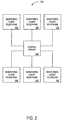
- FIG. 2shows a schematic diagram of the digital phone monitoring system of an embodiment of the present invention.
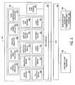
- FIG. 3shows a schematic diagram of a connection between a client telephone of an embodiment of the present invention and a telephony application programming Interface (TAPI).
- TAPItelephony application programming Interface
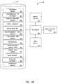
- FIG. 4Ashows a schematic diagram of a client telephone of an embodiment of the present invention.
- FIG. 4Bshows a schematic diagram of a client telephone of another embodiment of the present invention.
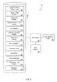
- FIG. 5shows a diagram of a central server in accordance with the digital phone monitoring system of FIG. 2 .
- FIG. 6shows an exemplary table of a monitored party database stored on a client telephone.
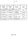
- FIG. 7Ashows an exemplary table of a client database stored on a central server.
- FIG. 7Bshows an exemplary DTMF code database stored on a central server.
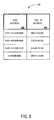
- FIG. 8shows an exemplary TCP/IP information database stored on a central server.
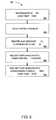
- FIG. 9shows a flowchart of the notification process performed by a central server.
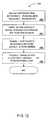
- FIG. 10shows a flowchart of the registration performed by a central server.
- FIG. 11shows a flowchart of the notification process performed by a central server.
- FIG. 12shows a flowchart of the queue manager process performed by a central server.
- FIG. 13shows a diagram of an embodiment of a client telephone.
- the telephone disclosed in various embodiments of the present inventionmay be configured in accordance with a “plug-and-play” protocol.
- the user of the telephonesimply plugs the telephone into a telephone jack.
- the telephoneautomatically connects to the central server, receives TCP/IP information from the server for future communications and registers the client. The client then selects the parties that the client wishes to monitor.
- the clientmay select parties to monitor by programming the parties' telephone numbers into the client's local telephone or by a directory lookup by name.
- the client's telephonecommunicates these telephone numbers to the central server and the central server verifies that the parties agree to be monitored. Once the parties agree, the parties register with the system.
- the clientmay also select parties to monitor by contacting the service associated with the central server off-line and submitting a request to monitor the specified parties.
- the central servicemay verify the agreement of the parties to be monitored by contacting them off-line (e.g., via telephone call, postal mail, e-mail).
- the process to select parties to monitormay be initiated by the monitored party.
- the party to be monitoredsubmits a request to the central server.
- the central serverremotely programs the monitoring party's telephone with the monitored party's status and identification information. It will be appreciated that the monitoring party may locally program its telephone. If the monitored party requests a monitoring party that is currently not a client to the status monitoring service, the service contacts the monitoring party off-line to determine if this party wishes to become a client to the service to receive status updates from the monitored party.
- FIG. 2a schematic diagram of the digital phone monitoring system of an embodiment of the present invention may be generally appreciated. It will be appreciated that an embodiment of the present invention defines a first telephone as a monitored client telephone 202 , and defines a second telephone as a monitoring telephone 206 . In particular, communication links between three monitoring client telephones 206 , a central server 204 and three monitored client telephones 202 are shown in FIG. 2 . Whenever a change in status of a monitored client telephone 202 occurs, monitored client telephone 202 communicates the status change via central server 204 to each monitoring client telephone 206 registered to receive status updates of that monitored client telephone 202 . It will be appreciated that the number of monitored client telephones 202 and monitoring client telephone 206 shown in FIG. 2 were arbitrarily chosen, and that alternative embodiments of the present invention may include any number of monitored and any number of monitoring client telephones.
- teenagersmay monitor their friends to determine which of their friends' phone lines are busy. When a teenager wants to call a friend, prior to even picking up and dialing the phone, the teenager automatically knows which friends are available to talk. The teenager may be presented with a list of friends, so that the teenager can instantly see which ones are available.
- a mothermay want to monitor her home telephone while at work. The mother may be interested in determining whether the phone is busy, or may wish to monitor the amount of time that her son, daughter or babysitter is on the phone per day.
- status informationmay be input at monitored client telephone 202 .
- the childmay enter a DTMF code into monitored client telephone 202 (e.g., *68).
- the code representing a status updateis sent to central server 204 .
- Central server 204forwards the status information to the child's mother's monitoring client telephone 206 , thereby informing the mother that her child has arrived at home.
- a supervisormay monitor when a telecommuting employee or consultant is working. For instance, the employee or consultant enters a predetermined code into monitored client telephone 202 when arriving at work. Monitored client telephone 202 sends the code to central server 204 . Central server 204 searches a DTMF code database 340 , as shown in FIG. 7B , retrieving the status corresponding to the code. Once retrieved, central server 204 sends the status to monitoring client telephone 206 . The status allows the supervisor to know when to contact the employee or consultant. Alternatively, this embodiment of the invention may provide the supervisor with additional information. For example, accounting and billing processes may calculate the total number of hours the employee worked. The status may also affect the billing rate for the called party.
- a billing programmay obtain such information as total time with a certain status (e.g., a status of “working”) and/or the total time on the phone with a particular status (e.g., “lunchtime”) and/or the applicable billing rate or other fee structure. Such a billing program could then generate an appropriate bill based thereon, and output a bill in printed, electronic file, email, fax or other forms.
- Status informationmay also be automatically determined by client telephone 202 , central server 204 , a monitoring client telephone, or any combination of the foregoing whether cooperating or not.
- a phonee.g., a cellular phone with GPS capability, cellular phones with other location abilities, calculating the Doppler effect of a signal received from a cellular phone
- the central server 204may be ascertained by the central server 204 by, e.g., receiving a signal from the cellular phone that indicates the location or approximate location of the cell phone.
- the phonemay broadcast a signal, which is received by a receiver. The strength and/or time of reception of the signal may allow the central server to determine the distance of the phone from the receiver.
- a low strength receiver that receives a signalmay indicate that the transmitter is within a certain area.
- a base unitmay be equipped to receive a signal from a handset unit only if the handset is within one hundred feet of the base. In another example, a base unit may readily determine when the handset is physically plugged into the base.
- FIG. 3a diagram of a Telephony Application Programming Interface (TAPI) 332 connected to monitoring client telephone 206 , monitored client telephone 202 and central server 204 may be generally appreciated.
- TAPITelephony Application Programming Interface
- Central server 204includes a plurality of communication applications 302 such as a call control application 304 , an interactive voice application 306 , a voice mail application 308 , a call center application 310 , and a TCP/IP conferencing application 312 .
- Central server 204also includes a registration service 314 , a notification service 316 , an encryption/decryption service 318 , a queue manager 320 , a start-up/self test service 322 , a monitoring service 324 , a TCP/IP database 326 , a client database 328 , a digital signature 336 , a call accounting service 338 and a DTMF code database 340 .
- a TAPI interface 330connects each of the above components to TAPI 332 .
- TAPI 332enables applications to access all the telephony options available on any machine.
- the communication applications 302including call control application 304 , interactive voice application 306 , voice mail application 308 , call center application 310 and TCP/IP conferencing application 312 may access all telephony options available on monitoring telephone 206 and monitored client telephone 202 .
- the applicationsmay access monitored client database 334 stored on monitoring client telephone 206 .
- TAPI 332is an architecture that provides simple and generic methods for making connections between two or more machines and provides each machine access to any media stream involved in that connection.
- TAPI 332abstracts call-control functionality to provide a common interface to applications that utilize different and seemingly incompatible communication protocols. This interface connects monitored client telephone 202 and monitoring client telephone 206 to central server 204 .
- client telephone 400may comprise either a monitoring client telephone 206 or a monitored client telephone 202 .
- Client telephone 400may be implemented as one or more separate devices.
- client telephone 400may be a single device or comprise a combination such as a telephone in communication with a separate sensor input device which is itself in communication with a separate transmitter device.
- client telephone 400may be a single device or comprise a combination such as a telephone in communication with a separate sensor input device which is itself in communication with a separate transmitter device.
- client telephone 400may be a single device or comprise a combination such as a telephone in communication with a separate sensor input device which is itself in communication with a separate transmitter device.
- Many more variationsare contemplated by the present disclosure.
- Client telephone 400operates under a multi-tasking, multithreaded operating system platform (e.g., UNIX, or WINDOWS NT by MICROSOFT of Redmond, Wash.). As shown, client telephone 400 includes a display device 402 , an input device 405 , a processor 404 and a data storage device 407 . Processor 404 is connected to a communication port 406 (e.g., network interface).
- a communication port 406e.g., network interface
- Input device 405may comprise a keyboard comprising a plurality of DTMF coded buttons. Alternatively or in addition, input device 405 may comprise a means for receiving other types of input.
- input device 405may comprise a GPS receiver for receiving information from a global positioning system. Such a GPS receiver typically receives broadcast signals that allow it to determine latitude, longitude, altitude, and time.
- input device 405may comprise a receiver that receives various wireless signals such as radio signals or infrared signals. Such receivers may be capable of receiving signals transmitted by cell phones, appliance remote controls such a s television remote controls, remote car lock actuators, remote garage door openers, PDAs, and other devices.
- Input device 405may comprise sensors or detectors that detect stimulus such as motion sensors (whether based on Doppler effects or other types of motion sensors), sensors that measure movement or actuation of a door or garage door; electrical sensors that detect activation or deactivation of air conditioners, lights and other devices; general electrical sensors that detect power consumption; weight sensors; temperature sensors; and combinations and equivalents thereof.
- motion sensorswhether based on Doppler effects or other types of motion sensors
- sensorsthat measure movement or actuation of a door or garage door
- electrical sensorsthat detect activation or deactivation of air conditioners, lights and other devices
- general electrical sensorsthat detect power consumption
- weight sensorsweight sensors
- temperature sensorsand combinations and equivalents thereof.
- Input device 405may comprise means for detecting the powering up or activation of the client telephone 400 .
- the input device 405may comprise a detector in communication with a circuit that activates or powers up a device, component of a device or plurality of components of a device.
- input device 405may comprise means for detecting the powering up or activation of (i) a telephone, such as a desktop phone, cellular phone or wireless phone; (ii) a computer; or (iii) a television.
- Input device 405may comprise a microphone or other audio reception device, possibly but not necessarily separate from the conventional microphone of a telephone for receiving spoken sounds. Such a microphone can be operational to detect, process and/or transmit sound even if the phone is in an inactive state, such as when it is not in use or when a receiver is cradled.
- Display device 402is an LCD or other type of display that shows the status of each party being monitored by client telephone 400 , in accordance with the data stored in monitored client database 334 .
- the displayshows a name and the current status of each party being monitored. It will be appreciated that client telephone 400 might not include display device 402 .
- Communications port 406provides the network interface to central server 204 using TCP/IP over the D channel on an ISDN telephone line.
- TCP/IPTransmission Control Protocol/Internet Protocol
- Data storage device 407includes a monitoring service 324 that processor 404 executes to provide client digital phone 400 with monitoring functionality.
- Data storage device 407also includes a startup/self-test service 410 , display manager 412 , digital signature 414 , encryption/decryption service 416 , monitored client database 334 , call accounting service 418 , a TAPI interface 420 , a communications applications 422 , a registration service 424 , a queue manager 426 , a DTMF code database 428 , and a notification service 430 .
- the communications applications 422 , the registration service 424 , the queue manager 426 , the DTMF code database 428 , and the notification service 430are utilized by the client telephone 400 in ways similar to those of the corresponding elements of the central server 204 , as described below.
- Startup/self-test service 410tests all hardware of client telephone 400 and loads the operating system and services. If connected via TAPI interface 420 to central server 204 , startup occurs when client telephone 400 is powered on. A startup may also occur if a user presses a re-boot key (not shown) located on client telephone 400 .
- Startup/self-test process 410typically includes three types of tests. It performs a checksum on EPROM, checks the ISDN line to confirm that the link with central server 204 on D and both B channels is up and running, and confirms that a “service provider identification” (SPID) matches the SPID pre-programmed on client telephone 400 .
- SPIDservice provider identification
- a SPIDis typically composed of the telephone number of client telephone 400 followed by four additional digits.
- central server 204assigns client telephone 400 TCP/IP information during the initial connection between client telephone 400 and central server 204 , and client telephone 400 subsequently stores that information. It will also be appreciated that, at startup, client telephone 400 sends its TCP/IP information to central server 204 , and central server 204 verifies that the TCP/IP information matches the assigned TCP/IP information of client telephone 400 .
- startup/self-test service 410may be applied to other types of communication technology.
- monitoring client telephone 206requests that central server 204 send status updates of the monitored client telephones 202 that it is authorized to receive.
- Monitoring client telephone 206seizes the D channel of the ISDN line and sends its DTMF codes.
- Central server 204reads the registration information and routes the call to registration service 314 via a communications (e.g., a DS-1 or DS-3) line.
- a communicationse.g., a DS-1 or DS-3
- monitoring client telephone 206Once monitoring client telephone 206 senses that the D channel communication link with central server 204 is established, it builds and encrypts an acknowledgment message with its SPID and a digital signature.
- Encryption/decryption service 416 of monitoring client telephone 206uses the public key of central server 204 to encrypt a message and generate a digital signature bundled with the message.
- Encryption/decryption service 318 of central server 204uses the private key of central server 204 to decrypt the message and validate the signature.
- the digital signatureprovides the security clearance of monitoring client telephone's 206 identity.
- central server 204If encryption/decryption service 318 of central server 204 successfully decrypts the message and verifies the digital signature of monitoring client telephone 206 , central server 204 sends an acknowledgment (ACK) message and its digital signature back to monitoring client telephone 206 . If the verification fails, server 204 instead sends a no-acknowledgment (NAK) and its digital signature back to monitoring client telephone 206 and drops the line. If monitoring client telephone 206 receives an ACK, it verifies the digital signature of central server 204 . If the verification is a success, monitoring client telephone 206 returns an ACK message to server 204 . If the verification fails, monitoring client telephone 206 returns a NAK message to server 204 and drops the line. If the communications between central server 204 and monitoring client telephone 206 resulted in ACKs, a session is established between monitoring client telephone 206 and registration service 314 of central server 204 .
- ACKacknowledgment
- NAKno-acknowledgment
- Registration service 314queries client database 328 to confirm that the account of monitoring client telephone 206 is in good standing.
- client database 328may include client billing and account information. It will be appreciated that the telephone company will typically provide the status monitoring service only to clients that have paid their telephone bills.
- Registration service 314then sends a clear to send (CTS) message to monitoring client telephone 206 that it is ready and waiting.
- CTSclear to send
- Monitoring client telephone 206receives the message and creates and sends a monitor message (MM) to registration service 314 .
- Registration service 314receives the message and queries client database 328 to obtain the current status of the monitored client telephones 202 that monitoring client telephone 206 is authorized to receive.
- the message from monitoring client telephone 206may include a request for a status update of specific monitored client telephones 206 .
- registration service 314uses the public key of monitoring client telephone 206 to encrypt the message, and return the message.
- Monitoring client telephone 206receives the message and decrypts it with its private key.
- Monitoring client telephone 206then updates monitored client database 334 and outputs the status of each party. Monitoring client telephone 206 then sends a message to registration service 314 of central server 204 acknowledging successful receipt of the status updates. Call accounting service 338 updates client database 328 to bill for the successful inquiry and drops the session by clearing the channel. Monitoring client telephone 206 recognizes that the channel is down and enters into a wait state until notification service 316 sends it updated status information.
- monitoring client telephone 206begins to automatically receive status updates without the need to poll central server 204 .
- Monitored client database 334includes monitoring information stored on storage device 407 of client telephone 400 . See FIG. 6 for an exemplary view of monitored client database 334 . As shown, the monitoring information includes monitored client SPID 602 , monitored client name 604 and status 606 of the monitored client. It will be appreciated that alternative embodiments of this invention may include other varied types of monitoring information. For example, monitored client database 334 may also include information such as total number of hours a monitored phone is busy, or total number of hours that a monitored telephone of an employee had an associated status of “working”.
- Display manager 412accesses monitored client database 334 , and displays this information on display device 402 of client telephone 400 (if display is the method of outputting status). Display manager 412 may also display messages originating from central server 204 . For example, display manager 412 may receive and display messages from central server 204 during registration of client telephone 400 .
- Digital signature 414provides client digital telephone 400 with the ability to verify the identity of a sender of TCP/IP message packets by creating and utilizing private and public keys. Digital signature 414 is included with encrypted messages sent between client telephone 400 and central server 204 . At client telephone 400 , the recipient's public key is used to encrypt a message and generate a digital signature string that is bundled therein. Upon receipt of the message, the recipient, such as central server 204 or another client telephone 400 , uses its private key to decrypt the message and validate the signature. Validating the signature verifies the message sender's identity.
- Call accounting service 418 on client telephone 400maintains up-to-date billing information.
- call accounting service 338 of central server 204sends telephone usage and billing updates to client's telephone 400 and stores the updates on storage device 407 .
- display manager 412accesses and displays the information on display device 402 .
- central server 204routinely initiates the transmission of accounting information to call accounting service 418 .
- call accounting central service 418retrieves telephone usage and billing updates from central server 204 in response to a request from the subscriber of client telephone 400 .
- FIG. 4Billustrates an embodiment of client telephone 400 .
- a phone 450is in communication via wire or wireless medium with a peripheral 455 , which is in turn in communication via wire or wireless medium with a display 460 .
- Display 460may comprise any device for presenting information visually, such as an LCD (liquid crystal display), monitor, or similar device.
- the functionality of the embodiments of the present inventionmay be distributed among the phone 450 , peripheral 455 and display 460 in an appropriate manner as would be apparent to one of ordinary skill in the art.
- peripheral 455may comprise a computer or similar computing device.
- a communication device 465permits the phone 450 to transmit and receive signals.
- Communication device 465may comprise means for transmitting and receiving data over a cable, wire or similar medium, as might be appropriate for a desktop phone.
- communication device 465may comprise means for transmitting and receiving data wirelessly via infrared, radio or similar signals, as might be appropriate for a cellular phone or other wireless device.
- peripheral 455 and display 460may compose an integral unit which is adapted to be connected to phone 450 .
- an integral unitmay comprise a single casing which encloses therein the peripheral 455 and the display 460 , while the casing defines an opening allowing a portion on the viewable area of the display to be seen outside the casing.
- Such an integral unit, or at least one of the individual peripheral and display,may be fitted to the phone 450 and detachably held thereto by the shape of the integral unit relative to the phone 450 .
- fitting to the phone detachably holding theretomay be accomplished by a fixing means such as a snap or similar means. Physical contact need not be required for communication between the phone 450 and the peripheral 455 .
- Central server 204operates under a multi-tasking, multithreaded operating system platform (e.g., UNIX, or WINDOWS NT by MICROSOFT of Redmond, Wash.).
- central server 204includes an input device 502 (e.g., CD ROM or floppy disk drive, keyboard), processor 504 connected to a communications port 506 , and a storage device 507 .
- Communications port 506provides a network interface, using TCP/IP over the D channel on an ISDN telephone line to connect central server 204 to monitored client telephone 202 and to monitoring client telephone 206 .
- TCP/IPTransmission Control Protocol
- Storage device 507includes monitoring service 324 , TAPI interface 330 , encryption/decryption service 318 , start-up/self-test service 322 , queue manager 320 , notification service 316 , registration service 314 , client database 328 , TCP/IP information database 326 , communication applications 302 , call accounting service 338 , digital signature 336 and DTMF code database 340 .
- Monitoring service 324provides central server 204 with a monitoring process in accordance with various embodiments of the present invention.
- TAPI interface 330enables applications, such as monitoring service 324 , to access all the telephony options available on any client telephone. For example, it provides monitoring service 324 with access to updated monitored client database 324 stored on client telephone 400 .
- Encryption/decryption service 318employs private and public keys to respectively decrypt and encrypt messages that are sent to client telephone 400 . This process also employs a digital signature 336 to verify the message sender's identity.
- Central server 204receives a digital string encrypted with a message from client telephone 400 . Upon receipt of the message, central server 204 uses its private key to decrypt the message and validate digital signature 336 . Similarly, when central server 204 sends a message to client telephone 400 , central server 204 utilizes the public key of client telephone 400 to encrypt the message and generate a digital signature string that is bundled therein. Client telephone 400 uses its private key to decrypt the message and validate the server's identity.
- Startup/self-test service 322initializes all components at startup and checks predetermined parameters when booting up. Tests include confirming that the ISDN line over D and both B channels that connect central server 204 and client telephones 400 is operating within predetermined parameters, and verifying that incoming messages to central server 204 are originated from authorized SPIDs. For example, at startup, startup/self-test service 410 of client telephone 400 sends a SPID verification message to central server 204 . Startup/self-test service 322 of central server 204 verifies that the SPID is authorized to receive monitoring information.
- Registration service 314registers monitored client telephones 202 and monitoring client telephones 206 , and maintains a list of current accounts and a list of the active connections between subscribers. Registration service 314 stores the list of current accounts on client database 328 and stores the list of active connections on TCP/IP information database 326 .
- FIG. 7shows an example of client database 328
- FIG. 8shows an example of TCP/IP information database 326 .
- notification service 316receives a status information update. Notification service 316 notifies queue manager 320 to transmit the status update to the appropriate monitoring client telephones 206 . Queue manager 320 receives notification of the status change from notification service 316 , queries client database 328 for the appropriate SPID(s) to contact, and transmits an indication of the change in status to the authorized clients designated by the appropriate SPID(s).
- Call accounting service 338maintains and sends billing information in real time to each client. More particularly, call accounting service 338 sends accounting and billing information in update packets to the client's telephone either (i) periodically (e.g., daily), or (2) in response to a client request. Accordingly, a client can always view in real time the specific charges associated with a call or view the running total for monthly bill. It will be appreciated that call accounting service 418 employed by client telephone 400 provides a subscriber with numerous functions for viewing and processing specific charges.
- monitored client database 334includes, for each party being monitored, a monitored client SPID 602 , a monitored client name 604 , and the current status 606 of monitored client telephone 202 . It will be appreciated that for a given monitored client SPID 602 , monitoring client telephone 206 may monitor more than one status. For example, the last entry 607 of monitored client database 334 includes more than one status.
- a number of methodsare available to enter data into monitored client database 334 .
- a client using input device 405locally inputs monitored client SPIDs 602 , and corresponding monitored client names 604 into monitored client database 334 .
- central server 204in response to a request from monitoring client telephone 206 , remotely updates the SPIDs of monitored client database 334 .
- a clientrequests status monitoring by either calling a telephone company's toll-free number to verbally request monitoring, or by electronically submitting a request via an Interactive Voice Response (IVR) unit. It will be appreciated that a Voice Response Unit (VRU) may also be used.
- central server 204must receive permission from the party at monitored client telephone 202 .
- the central telephone officerequests permission by electronically sending a request via central server 204 to monitored client telephone 202 , or by contacting the party using another method. Other methods may include, for example, a telephone call, an e-mail, or a letter.
- central server 204receives permission, it sends an authorizing signal to monitoring client telephone 206 . Once authorized, monitoring client telephone 206 receives status updates from central server 204 , and enters the updates into monitored party database 334 .
- Display device 402 of the monitoring client telephone 206displays each status update 606 .
- monitored client telephone 202may initiate the request to be monitored by monitoring client telephone 206 .
- central server 204electronically receives the request, or the central telephone service receives the request using another manner, the service requests permission to send monitoring client telephone 206 status updates of monitored client telephone 202 .
- the request for permissionmay be electronically submitted by central server 204 or provided using another manner.
- a subscriber at monitoring client telephone 206may monitor a status change of a particular predetermined condition. For example, a subscriber may choose to monitor the “busy” status of monitored client telephone 202 . Alternatively, a subscriber may choose to monitor when the person at monitored client telephone 202 enters a DTMF code indicative of a working status.
- a subscriber at monitoring client telephone 206may monitor a status change of a particular predetermined condition. For example, a subscriber may choose to monitor the “busy” status of monitored client telephone 202 . Alternatively, a subscriber may choose to monitor when the person at monitored client telephone 202 enters a DTMF code indicative of a working status.
- FIG. 7(A)a diagram of an exemplary client database 328 stored on central server 204 may be better appreciated.
- this databaseincludes entries for each monitored client telephone 202 that is registered with central server 204 .
- Each entryincludes the party being monitored, identifiable by monitored client SPID 702 , the party receiving the status updates, identifiable by monitoring client SPID 704 , and the particular status changes monitoring client telephone 206 will receive, shown as monitored status 706 and a current status 708 .
- the current status 708 of an entry of client database 328may include more than one status.
- the process of updating and maintaining client database 328will be discussed in conjunction with the description of the registration process shown in FIG. 9 .
- a diagram of exemplary DTMF code database 340 stored at central server 204may be better appreciated. As shown, this database includes a status 714 assigned to each DTMF code 712 . Notification service 316 of central server 204 uses DTMF code database 710 to translate incoming DTMF codes to an appropriate status. It will be appreciated that a DTMF code may represent information other than a status. For example, a DTMF code may represent a request for billing information.
- FIG. 8a diagram of exemplary TCP/IP information database 326 stored at central server 204 may be better appreciated.
- this databaseincludes entries for each client telephone 400 registered with central server 204 .
- Each entryincludes a SPID address 802 and a corresponding TCP/IP address 804 .
- a TCP/IP address information 804is issued to each client telephone 400 registered with central server 204 .
- central server 204communicates with other nodes and clients based on their assigned TCP/IP address 804 .
- the header portion of messages sent between monitored and monitoring client telephones 400 and central server 204typically include a TCP/IP address 804 .
- central server 204uses the SPID address 802 listed in the TCP/IP database 326 to verify that the TCP/IP address included within the message's header portion is correct.
- central server 204registers the subscriber of monitoring client telephone 206 .
- the subscriber of monitoring client telephone 206selects the parties the subscriber wishes to monitor.
- central server 204registers the parties to be monitored. It will be appreciated that prior to registering these parties, central server 204 may request each party's permission to be monitored by the subscriber of monitoring client telephone 206 .
- central server 204receives TCP/IP packets from monitored client telephone 202 .
- central server 204transmits the TCP/IP packets to the monitoring client telephone 202 configured to receive the status updates. Once received, monitoring client telephone 206 displays the status to the subscriber.
- FIG. 9shows the general steps of an embodiment of the present invention, and that FIGS. 10-12 described below will explain each step in greater detail.
- monitored client telephone 202may register prior to monitoring client telephone 206 . Furthermore, monitored client telephone 202 may select the parties that it wishes to provide status updates. Prior to sending the status updates, monitoring client telephone 206 must register and provide central server 204 of the central telephone permission to receive the status information.
- client telephone 400When a party at a client telephone 400 wishes to register as a subscriber of a monitored client telephone 202 in step 906 , or as a monitoring client telephone 306 in step 902 , client telephone 400 seizes the D channel of the ISDN line and sends the registration information to central server 204 of a telephone station's central office. Central server 204 reads the registration information and routes the call to registration service 314 via a DS-1 or DS-3 line.
- Registration service 314senses the incoming call and central server 204 goes off-hook on that line. Once off-hook, registration service 314 opens a communication link between central server 204 and the party wishing to register.
- the request for a party's permission to be monitored by the subscribermay be accomplished in a variety of ways.
- the partymay affirmatively register his willingness to be monitored, whether or not a request for permission has been directed to him. Accordingly, a subscriber need not select parties to monitor—the parties may indicate that they are to be monitored.
- the partymay enter an indication of one or more subscribers that are authorized to monitor the party.
- Such an indicationmay be entered via a phone, for example, by actuating numeric keys (e.g., on input device 405 ) to indicate the phone number of such authorized subscribers.
- Such an indicationmay also be entered via a phone, for example, by communicating with a VRU (Voice Response Unit).
- VRUVoice Response Unit
- Such a method of entrycould be performed via any public or private phone, whether or not the that phone had other capabilities described herein.
- An indication of one or more subscribers that are authorized to monitor the partymay be entered via a computer communicating with a web site, which in turn provides the information to, e.g., central server 204 .
- the indication of subscribers that are authorized to monitor the partymay be made automatically without much or any input from the party.
- the partymay set or accept a threshold such that people the party calls (or people that call the party) more than the threshold are authorized to monitor the party.
- a list of one or more subscribers that are authorized to monitor the partymay be stored locally on the party's phone or other device and/or stored remotely on central server 204 .
- Various partiesmay be authorized to monitor only certain kinds of statuses of a particular monitored party. For example, a first group may be authorized to monitor all statuses of a particular party, while a second group may be authorized to monitor only certain statuses of that party.
- various partiesmay be able to attain different levels of access by paying. For example, telemarketers and other businesses may be able to pay to ascertain certain statuses of a party.
- the status of a monitored partymay be employed as a “block” against certain calls. In certain embodiments, it is not necessary for a monitoring party to register at all. The block applies to certain callers or all callers, irrespective of whether any party registered in any way to receive status.
- a statusmay simply indicate that no calls are allowed to get through to the monitored party (i.e. all calls blocked). In another embodiment, a status may indicate that only certain people are blocked, or that only certain people are unblocked (i.e. may call).
- certain partiesmay be allowed to always get through a block. For example, it may be desirable for the monitored party to always permit a spouse and parent to circumvent a block. In always granting such parties access, their phones could be always granted access to the monitored party (e.g., by receiving an identifying signal (e.g., ANI, SPID) from such phone and comparing that signal with a list of authorized phones), or those parties could be provided with special access codes. Upon calling the monitored party when a block is in effect, the party would enter the access code and be granted access by allowing there call to get through.
- an identifying signale.g., ANI, SPID
- a monitoring party that attempts to call the monitored party but is “blocked”may, e.g., receive a busy signal, receive a particular kind of busy signal, or receive a particular audio message.
- Certain locations or certain timesmay be marked as “blocked”, thereby preventing some or all calls from going through. For example, from a phone which has a location that may be determined, a party may enter a code that indicates the current location as a “blocked” location or a location where a certain status is to be established. For example, a party may enter an office building and enter a code via a wireless phone. This could establish a status of “unavailable” while the party is in the building.
- the location of the phone upon entry of the codemay be determined, such that, e.g., that location alone is an area in which the status would be established as “unavailable”.
- a radiusmay be set such that when the phone is within the radius of that location the status would be established as “unavailable”. Such a radius may be predetermined, or alterable (e.g., by the party).
- an email, message or other transmissionmay be automatically sent to monitoring parties.
- a group of certain partiesmay be established, and a member of the group may determine who in the group is calling another, and who is free. The identity of those called by other group members may or may not be made available.
- establishing such a groupcan allow a member of the group to sort a list of the other members in order of, e.g., frequency of calls to the parties, frequency of calls from the parties, frequency of calls to or from the parties and/or frequency of calls from the parties to any member of the group.
- the ratingmay be based on, e.g., number of such calls, duration of such calls.
- a rating according to this embodimentmay confer rewards such as discounted or free products, discounted or free services from the phone network provider.
- the rankmay be displayed or otherwise made known to member of the group, conferring psychological rewards or penalties upon members.
- a group of membersmay eavesdrop on other members who are communicating with one another via, e.g., voice, text messaging. Such eavesdropping may be automatically allowed, or may require permission from those engaged in communicating. It may also be advantageous to allow members of the group to access a “log” of prior communication (e.g., recorded voice, recorded text messages) to allow eavesdropper to catch up on what had been communicating prior to eavesdropping.
- a “log” of prior communicatione.g., recorded voice, recorded text messages
- registration service 314receives a request from a registering client telephone 400 for a TCP/IP address and a security clearance.
- the security clearance processutilizes a digital signature and encryption to secure the messages sent between client telephone 400 and central server 204 . More particularly, once client telephone 400 senses that the D channel communication link with central server 204 is established, it builds and encrypts an acknowledgment message with its SPID and a digital signature.
- Client Telephone 400uses a public key of central server 204 to encrypt a message and generate a digital signature bundled with the message.
- the recipient of the messageuses its private key to decrypt the message and validate the signature.
- the digital signatureprovides the security clearance of the message sender's identity. It will be appreciated that all communications between central server 204 and client telephone are encrypted and include a digital signature.
- central server 204sends an acknowledgment (ACK) message and its digital signature back to client telephone 400 . If the verification fails, central server 204 instead sends a no-acknowledgment (NAK) and its digital signature back to client telephone 400 and drops the line. If client telephone 400 receives an ACK, it verifies the digital signature of central server 204 . If the verification is a success, client telephone 400 returns an ACK message to central server 204 . If the verification fails, client telephone 400 returns a NAK message to central server 204 and drops the line. If these communications resulted in ACKs, a session is established between client telephone 400 and registration service 314 of central server 204 .
- ACKacknowledgment
- NAKno-acknowledgment
- registration service 314receives a SPID/MAC (Media Access Control Layer) address from registering client telephone 400 . It will be appreciated that the SPID/MAC was either pre-programmed into registering client telephone 400 or was previously assigned by central server 204 .
- registration service 314checks the SPID/MAC format. In step 1008 , if the format is incorrect, registration service 314 sends an “unable to process request” message to client telephone 400 . If the format is correct, in step 1010 , registration service 314 issues client telephone 400 a TCP/IP address.
- SPID/MACMedia Access Control Layer
- registration service 314stores the SPID of client telephone 400 into the appropriate field of client database 522 . If client telephone 400 is a monitored client telephone 202 , registration service 314 stores the SPID as a monitored client SPID 702 . If client telephone 400 is a monitoring client telephone 206 , registration service 314 stores the SPID as a monitoring client SPID 704 . In step 1014 , registration service 314 stores the SPID address and the corresponding TCP/IP address in TCP/IP address database 326 . Once client database 328 and TCP/IP address database 326 are updated, registration service 314 sends a registration acknowledgment message back to client telephone 400 indicating that it is now registered.
- the subscriber of client telephone 400selects one or more parties that the subscriber wishes to monitor.
- the subscribermay enter each parties' phone number into monitored client database 334 , where each parties phone number is mapped to a SPID. Once entered, monitoring client telephone 206 sends these telephone numbers to registration service 314 .
- the subscribermay also select parties to monitor by contacting the service associated with registration service 314 off-line, and submitting a request to monitor the specified parties.
- registration service 314verifies that the parties agree to be monitored. If a party is a current subscriber of the status monitoring service, registration service 314 of central server 204 may electronically send the permission request directly to that party's client telephone 400 . Alternatively, if a party is not a current subscriber, the central service may verify that the party agrees to be monitored by contacting that person off-line (e.g., via telephone call, postal mail, e-mail).
- registration service 314registers the monitored party which the subscriber selected. It will be appreciated that if the party agrees to be monitored and does not currently included as an entry within the TCP/IP information database 326 of central server 204 , registration service 314 registers this party by performing the steps of the registration process described above and shown in FIG. 10 . For all monitored parties, registration service 314 updates client database 328 with each party's monitored client SPID 702 , the status 706 being monitored, and the monitoring client SPID 704 of the subscriber who will receive the status updates of the monitored client.
- registration service 314sends an indication to monitoring client telephone 206 that the parties agreed to be monitored and are registered at central server 204 .
- central server 204in response to a request from monitoring client telephone 206 , remotely updates monitored client database 334 with the SPIDs 602 and the corresponding monitored client names 604 .
- the subscriberlocally inputs monitored client SPIDs 602 , and corresponding monitored client names 604 into monitored client database 334 .
- notification service 316 of central server 204may be better appreciated.
- registration service 314registers the monitoring and monitored parties
- monitored client telephone 202automatically sends status updates via central server 204 to the subscriber of monitoring client telephone 206 .
- Monitored client telephone 202sends each status update in a TCP/IP packet when its status changes.
- the status changemay be a DTMF code entered by the monitored party into monitored client telephone 202 .
- a party when workingmay enter a DTMF code.
- monitored client telephone 202 of the first monitored partywill submit status updates of both parties to central server 204 .
- the status updatemay show that the first monitored party is electronically connected to the second monitored party.
- monitored client telephone 202Prior to sending a packet of status updates, monitored client telephone 202 uses a public key of central server 204 to encrypt and provide a digital signature within the TCP/IP packet.
- notification service 316 of central server 204receives the encrypted TCP/IP packet from monitored client telephone 202 .
- Notification 316 serviceuses the private key to decrypt and verify the packet's digital signature.
- Notification service 316also compares the SPID and TCP/IP address information provider in the header portion of the TCP/IP packet to the appropriate entry in the TCP/IP database 326 to verify the source of the status update. Once the source of the update is verified, notification service 316 stores the status to current status 708 of the appropriate record(s).
- notification service 316queries client database 328 to retrieve a record that includes monitored client telephone 202 .
- notification service 316determines if this record applies to the status update it received. More specifically, it determines if this status update corresponds to the status information that monitoring client telephone 206 is configured to receive. If the status corresponds, in step 1110 , notification service 316 transmits the TCP/IP packet to queue manager 320 . If the status does not correspond, in step 1108 , notification service 316 determines if there is another record corresponding to monitored client telephone 202 . If there is another record, notification service 316 determines if this record applies to the status update it received from monitored client telephone 202 . It will be appreciated that this process continues until notification service 316 reviews all records of client database 328 that apply to monitored client telephone 202 . Once the review of client database 328 records is completed, in step 1112 , notification process 1100 ends.
- a queuing process 1200 performed by queue manager 320 of central server 204may be better appreciated.
- the processbegins in step 1202 when queue manager 320 receives a TCP/IP packet from notification service 316 .
- This packetincludes a status update, and an origin and a destination SPID of respective monitored client telephone 202 and monitoring client telephone 206 .
- queue manager 320retrieves from TCP/IP address database 326 the TCP/IP address of monitoring client telephone 206 that corresponds to the destination SPID.
- queue manager 320transmits the TCP/IP packet to the TCP/IP address of the appropriate monitoring client telephone 206 .
- step 1208if monitoring client telephone 206 successfully received the TCP/IP packet, queue manager 320 receives an acknowledgment of the successful transmission.
- Queue manager 320updates client database 328 for billing purposes and drops the session with monitoring client telephone 206 .
- central server 204may be encrypted.
- the TCP/IP information that monitoring client telephone 206 receivesis encrypted.
- Monitoring client telephone 206uses its private key to decrypt and access the status update provided in the TCP/IP packet.
- the communicationsdo not necessarily have to be encrypted.
- Monitoring client telephone 206updates monitored client database 334 with the status update.
- Display manager 412 of monitoring client telephone 206displays the status update on display device 402 . Accordingly, the subscriber of monitoring client telephone 206 is capable of monitoring the status of the parties of monitored client telephones 202 without even picking up the telephone.
- client digital phone 400includes a handset 1302 , an LCD display 1304 , DTMF buttons 1306 , extension status indicators 1308 and a volume control 1310 .
- the screen of sample LCD display 1304shows the current status of the parties of monitored client telephones 202 .
- the four parties shown on LCD display 1304are purely illustrative of the status information provided to subscribers, and that any number of parties of monitored client telephones 202 may be displayed. If the number of monitored parties requires more display space than is available on LCD display 1304 , the status entries may continuously scroll.
- client telephone 400may include scrolling buttons, that allow a subscriber to scroll though pages of client digital phones 400 that are being monitored.
- an alternative embodiment of the present inventionmay utilize the Internet and other networks to transfer status information of a pre-selected list of frequently called telephone numbers from central server 204 of the central service to the party of monitoring client telephone 206 .
- central server 204receives status information as described above, but instead of sending the information to monitoring client telephone 206 , central server 204 posts the status information to, e.g., the monitoring party's web page account.
- central server 204may comprise a plurality of devices that are located in numerous geographical regions. Such devices would communicate with each other for the purpose of transmitting status update packets between different geographic regions. Accordingly, each device includes in its client database, records of all monitored and monitoring clients from all regions. When a device is notified of a status change of a monitored party, it transmits the status update packet to the device servicing the region where the monitoring party is located.
- each local regionmay include one device.
- unique separate serversmay support each region by communicating with each other. It will be further appreciated that a single server may support multiple regions or may be distributed across multiple regions.
- a statusmay indicate who the monitored party is communicating with.
- the central servercould readily determine who the monitored party was communicating with, and make that information available to authorized monitoring parties.
- a statusmay indicate who the monitored party is located near. As described herein, the location or approximate location of a phone may be determined. Accordingly, it may be determined which phones are located near the monitored phone. Such a status would be advantageous to, for example, a parent monitoring a child.
- a statusmay indicate the state of the battery of a battery-powered phone. Such a status would be advantageous in allowing a monitoring party to determine whether a call to the monitored party would unduly deplete the battery of the monitored party.
- a statusmay indicate the local time of the monitored party. For example, a monitored party may have traveled to a different time zone, and monitoring party can be informed of the local time of the monitored party. Such information would allow a monitoring party to exercise judgment as to whether it would be an appropriate time to call the monitored party. Such a status may also be used by the monitored party to block certain calls, for example, all calls after 11:00 PM of the local time of the monitored party.
- a statusmay indicate whether the monitored party is using a text messaging or similar feature of a phone, such as a wireless phone with text messaging or email capability. Such a status may indicate, e.g., whether a monitored party is (i) available for text messaging, (ii) currently entering text, (iii) currently reading text, (iv) scrolling, and/or (v) playing online games or engaging in other online activity.
- a statusmay indicate whether the monitored party wants top receive calls, or when the monitored party would like to receive calls. Such a capability may be extended only to certain kinds of calls. For example, the monitored party may desire to receive a call from customer service, or a call indicating a desired weather report or news report.
- the status informationmay trigger a message sent to the monitoring party.
- a messagemay be via email, instant messaging, audio or other means.
- Status informationneed not be displayed, or might be displayed in conjunction with other types of output of status information.
- status informationcould be output through the speaker on the phone, another speaker or other audio device.
- statusmay be output as messages such as “Bill is working right now”, “Bill's is in New York and the local time is midnight”, or “Bill's battery is low. Please use your judgment whether you should call him now.”
- Status informationmay also be indicated by a busy signal, or a different kind of busy signal than is normally output. Different busy signals may be used for different statuses. The selection of busy signals used for different statuses may be selected by the monitoring party and/or the monitored party.
- a statusmay indicate whether the monitored party is moving, the speed and/or the direction of movement.
- the location of a car phone or cellular phonemay be periodically determined, and thus a changing location can indicate that the monitored party is moving.
- the speed and direction of movementcan likewise be easily determined. It may be desirable to “block” calls when in moving. It may also be desirable to prevent outgoing calls while in motion. Similarly, it may be advantageous to require an override code to be entered into a phone while in motion in order to permit an outgoing call. For example, a state law may prohibit talking on a phone while driving a car.
- the particular patterns of status changesmay be learned. For example, if a certain location is established as having a status during certain times, or a certain status is periodically established during certain times of the day, these patterns may be learned by appropriate machine learning techniques, as is well understood by those skilled in the art. Thus, the party may be able to avoid manually entering status information and other information if the requisite pattern has been learned. Similarly, once the pattern has been learned, the future status at certain times may be predicted. Messages and other information may be adapted to this prediction. For example, if it is learned that a status of unavailable occurs every work day between 2:00 PM and 3:00 PM then a calling party calling at 2:30 PM may be informed that the called party will become available at 3:00 PM.
- An additional statusmay be that the phone has detected a noise, or a noise exceeding a certain decibel level, at any time or while its status was a predetermined status, such as “nobody home”. Such an embodiment would be advantageous for monitoring a home while it is vacant. Detecting a noise could trigger, e.g., a call to a predetermined number (such as a work number) and could also play back during that call the previous thirty seconds of sound recorded prior to the detected noise.
- a predetermined numbersuch as a work number
- Another type of remote monitoringwould be to permit information from the phone to be transmitted to another location. For example, a log of calls made to the phone in the last four hours may be transmitted (e.g., via fax, email, over the phone) when a code is received (e.g., via a work phone, via email). Additionally, after receiving such a log, a party could indicate which calls he wanted to return (e.g., upon arriving back home). In one embodiment such calls may be returned without dialing; the order of returned calls could be established when indicating which calls to return, and the calls made by merely picking up the phone
Landscapes
- Engineering & Computer Science (AREA)
- Signal Processing (AREA)
- Computer Networks & Wireless Communication (AREA)
- Telephonic Communication Services (AREA)
- Sub-Exchange Stations And Push- Button Telephones (AREA)
Abstract
Description
Claims (11)
Priority Applications (1)
| Application Number | Priority Date | Filing Date | Title |
|---|---|---|---|
| US11/316,758US8027448B2 (en) | 1999-03-31 | 2005-12-23 | Method and apparatus for monitoring telephone status |
Applications Claiming Priority (3)
| Application Number | Priority Date | Filing Date | Title |
|---|---|---|---|
| US28236099A | 1999-03-31 | 1999-03-31 | |
| US10/090,795US7010110B2 (en) | 1999-03-31 | 2002-03-05 | Method and apparatus for monitoring telephone status |
| US11/316,758US8027448B2 (en) | 1999-03-31 | 2005-12-23 | Method and apparatus for monitoring telephone status |
Related Parent Applications (1)
| Application Number | Title | Priority Date | Filing Date |
|---|---|---|---|
| US10/090,795DivisionUS7010110B2 (en) | 1999-03-31 | 2002-03-05 | Method and apparatus for monitoring telephone status |
Publications (2)
| Publication Number | Publication Date |
|---|---|
| US20060140350A1 US20060140350A1 (en) | 2006-06-29 |
| US8027448B2true US8027448B2 (en) | 2011-09-27 |
Family
ID=27804069
Family Applications (6)
| Application Number | Title | Priority Date | Filing Date |
|---|---|---|---|
| US10/090,795Expired - LifetimeUS7010110B2 (en) | 1999-03-31 | 2002-03-05 | Method and apparatus for monitoring telephone status |
| US11/316,758Expired - Fee RelatedUS8027448B2 (en) | 1999-03-31 | 2005-12-23 | Method and apparatus for monitoring telephone status |
| US11/338,151Expired - LifetimeUS7260201B2 (en) | 1998-03-31 | 2006-01-24 | Method and apparatus for monitoring telephone status |
| US11/421,517AbandonedUS20060203968A1 (en) | 1999-03-31 | 2006-06-01 | Method and apparatus for monitoring telephone status |
| US11/421,535Expired - Fee RelatedUS9154619B2 (en) | 1999-03-31 | 2006-06-01 | Method and apparatus for monitoring telephone status |
| US11/421,524Expired - Fee RelatedUS8204199B2 (en) | 1999-03-31 | 2006-06-01 | Method and apparatus for monitoring device status |
Family Applications Before (1)
| Application Number | Title | Priority Date | Filing Date |
|---|---|---|---|
| US10/090,795Expired - LifetimeUS7010110B2 (en) | 1999-03-31 | 2002-03-05 | Method and apparatus for monitoring telephone status |
Family Applications After (4)
| Application Number | Title | Priority Date | Filing Date |
|---|---|---|---|
| US11/338,151Expired - LifetimeUS7260201B2 (en) | 1998-03-31 | 2006-01-24 | Method and apparatus for monitoring telephone status |
| US11/421,517AbandonedUS20060203968A1 (en) | 1999-03-31 | 2006-06-01 | Method and apparatus for monitoring telephone status |
| US11/421,535Expired - Fee RelatedUS9154619B2 (en) | 1999-03-31 | 2006-06-01 | Method and apparatus for monitoring telephone status |
| US11/421,524Expired - Fee RelatedUS8204199B2 (en) | 1999-03-31 | 2006-06-01 | Method and apparatus for monitoring device status |
Country Status (5)
| Country | Link |
|---|---|
| US (6) | US7010110B2 (en) |
| EP (1) | EP1488623B1 (en) |
| JP (2) | JP2005520404A (en) |
| AU (1) | AU2003222259A1 (en) |
| WO (1) | WO2003077517A1 (en) |
Cited By (6)
| Publication number | Priority date | Publication date | Assignee | Title |
|---|---|---|---|---|
| US20060203970A1 (en)* | 1999-03-31 | 2006-09-14 | Jorasch James A | Method and apparatus for monitoring telephone status |
| US20080244704A1 (en)* | 2007-01-17 | 2008-10-02 | Lotter Robert A | Mobile communication device monitoring systems and methods |
| US20100064014A1 (en)* | 2008-09-05 | 2010-03-11 | Skype Limited | Distributing presence information |
| US8712396B2 (en) | 2007-01-17 | 2014-04-29 | Eagency, Inc. | Mobile communication device monitoring systems and methods |
| US9324074B2 (en) | 2007-01-17 | 2016-04-26 | Eagency, Inc. | Mobile communication device monitoring systems and methods |
| US10045327B2 (en) | 2007-01-17 | 2018-08-07 | Eagency, Inc. | Mobile communication device monitoring systems and methods |
Families Citing this family (62)
| Publication number | Priority date | Publication date | Assignee | Title |
|---|---|---|---|---|
| US9311399B2 (en) | 1999-09-07 | 2016-04-12 | C. Douglass Thomas | System and method for providing an updating on-line forms and registrations |
| US7747592B2 (en)* | 1999-09-07 | 2010-06-29 | Thomas C Douglass | Method and system for monitoring domain name registrations |
| US6804339B1 (en)* | 2000-01-19 | 2004-10-12 | Siemens Information And Communication Networks, Inc. | Real-time object-oriented database for TAPI service providers |
| US6975715B1 (en)* | 2000-02-09 | 2005-12-13 | Siemens Communications, Inc. | System and method for reporting the addition and deletion of TAPI line and phone devices in absence of such notifiction from a PBX |
| GB2365257B (en)* | 2000-07-28 | 2003-03-12 | Data Information Systems Ltd | Telephone status/availability system |
| WO2002035816A1 (en)* | 2000-10-26 | 2002-05-02 | Mitsubishi Denki Kabushiki Kaisha | Internet telephone network system, network access method and talking device adapter |
| US7899167B1 (en)* | 2003-08-15 | 2011-03-01 | Securus Technologies, Inc. | Centralized call processing |
| US6931007B2 (en)* | 2001-07-25 | 2005-08-16 | Longboard, Inc. | System and method of serving data messages |
| US7415417B2 (en)* | 2002-03-15 | 2008-08-19 | Avaya Technology Corp. | Presence awareness agent |
| US9635540B2 (en)* | 2002-03-25 | 2017-04-25 | Jeffrey D. Mullen | Systems and methods for locating cellular phones and security measures for the same |
| US7103034B1 (en)* | 2002-05-09 | 2006-09-05 | Cisco Technology, Inc. | Approach for tracking internet protocol telephony devices in networks |
| US7146163B2 (en)* | 2002-10-01 | 2006-12-05 | Isp Operator Corporation | Sender-address-based telecommunications operator callback system and method |
| US7861088B1 (en)* | 2002-12-10 | 2010-12-28 | Verizon Laboratories Inc. | Method and system for verifiably recording voice communications |
| US7573999B2 (en)* | 2002-12-31 | 2009-08-11 | At&T Intellectual Property I, L.P. | Computer telephony integration (CTI) complete healthcare contact center |
| US7620170B2 (en)* | 2002-12-31 | 2009-11-17 | At&T Intellectual Property I, L.P. | Computer telephony integration (CTI) complete customer contact center |
| US7248688B2 (en) | 2003-01-27 | 2007-07-24 | Bellsouth Intellectual Property Corporation | Virtual physician office systems and methods |
| US20050043010A1 (en)* | 2003-08-19 | 2005-02-24 | Ron Rosansky | Call accounting for wireless handheld device |
| JP4629679B2 (en)* | 2003-12-09 | 2011-02-09 | テルコーディア・テクノロジーズ・インコーポレーテッド | Method and system for free internet protocol communication service |
| CN100456782C (en)* | 2003-12-16 | 2009-01-28 | 腾讯科技(深圳)有限公司 | A phone status information presentation system and its implementation method |
| US8229454B1 (en) | 2004-03-22 | 2012-07-24 | Avaya Inc. | Personal location information management |
| US20060031461A1 (en)* | 2004-05-14 | 2006-02-09 | Mathur Harish C | Deferred method of sending information |
| US7940919B2 (en)* | 2005-03-14 | 2011-05-10 | Inventec Multimedia & Telecom Corporation | Periodic and automatic telephone redialling system and method |
| US8024438B2 (en)* | 2005-03-31 | 2011-09-20 | At&T Intellectual Property, I, L.P. | Methods, systems, and computer program products for implementing bandwidth management services |
| US8306033B2 (en)* | 2005-03-31 | 2012-11-06 | At&T Intellectual Property I, L.P. | Methods, systems, and computer program products for providing traffic control services |
| US8335239B2 (en) | 2005-03-31 | 2012-12-18 | At&T Intellectual Property I, L.P. | Methods, systems, and devices for bandwidth conservation |
| US8098582B2 (en)* | 2005-03-31 | 2012-01-17 | At&T Intellectual Property I, L.P. | Methods, systems, and computer program products for implementing bandwidth control services |
| GB2425686B (en)* | 2005-04-29 | 2007-05-30 | Motorola Inc | Method and apparatus for notification in a cellular communication system |
| US8351587B2 (en)* | 2005-05-24 | 2013-01-08 | Siemens Enterprise Communications, Inc. | Method and apparatus for automatic notification of conference status |
| US7881447B1 (en)* | 2005-07-19 | 2011-02-01 | Sprint Communications Company L.P. | Conference call text messaging protocol using caller ID screen |
| BRPI0615078A2 (en)* | 2005-08-26 | 2011-05-03 | Tekelec Us | computer program methods, systems, and products for dynamically controlling a pstn network element from an ip network element using signaling |
| US8701148B2 (en) | 2005-09-01 | 2014-04-15 | At&T Intellectual Property I, L.P. | Methods, systems, and devices for bandwidth conservation |
| US8104054B2 (en) | 2005-09-01 | 2012-01-24 | At&T Intellectual Property I, L.P. | Methods, systems, and devices for bandwidth conservation |
| US8363812B1 (en) | 2005-09-22 | 2013-01-29 | Verizon Patent And Licensing Inc. | Method and system for providing call parking in a SIP-based network |
| US20070088839A1 (en)* | 2005-10-19 | 2007-04-19 | Nortel Networks Limited | Local time related presence automation and session control |
| DE602006000817T2 (en)* | 2006-02-03 | 2008-07-17 | Research In Motion Ltd., Waterloo | System and method for controlling data communication between a server and a client device |
| US7634262B1 (en)* | 2006-03-07 | 2009-12-15 | Trend Micro, Inc. | Virus pattern update for mobile device |
| US20070243858A1 (en)* | 2006-04-18 | 2007-10-18 | Tekelec | Methods, systems, and computer program products for integrated notification of missed calls across multiple phone types |
| US8442511B2 (en)* | 2006-09-05 | 2013-05-14 | Richard Woods | Mobile phone control employs interrupt upon excessive speed to force hang-up and transmit hang-up state to other locations |
| US8194847B2 (en)* | 2006-11-30 | 2012-06-05 | Verizon Patent And Licensing Inc. | Method and system for voice monitoring |
| US8199890B2 (en)* | 2007-02-06 | 2012-06-12 | Cisco Technology, Inc. | Camp on location |
| JP4375469B2 (en)* | 2007-09-28 | 2009-12-02 | 双葉電子工業株式会社 | Radio control model equipment, control device for radio control model equipment, frequency hopping pattern selection method |
| GB2454651A (en)* | 2007-10-31 | 2009-05-20 | Symbian Software Ltd | Communication device which calculates the present time at an intended call recipient's location |
| US8762205B2 (en)* | 2008-01-17 | 2014-06-24 | International Business Machines Corporation | Method for delivering businesses enterprises advertising via instant messaging |
| US7831675B2 (en)* | 2008-01-17 | 2010-11-09 | International Business Machines Corporation | Method for interacting with infrastructure devices via instant messaging |
| JP2009253596A (en)* | 2008-04-04 | 2009-10-29 | Sharp Corp | Communication terminal |
| GB2459107B (en)* | 2008-04-09 | 2012-11-14 | Ubiquisys Ltd | Access point |
| KR20100042678A (en) | 2008-10-02 | 2010-04-27 | 삼성전자주식회사 | Apparatus and method for presence service in portable communication system |
| US8401521B2 (en)* | 2008-11-25 | 2013-03-19 | Broadcom Corporation | Enabling remote and anonymous control of mobile and portable multimedia devices for security, tracking and recovery |
| US8433304B2 (en)* | 2009-01-22 | 2013-04-30 | Centurylink Intellectual Property Llc | System and method for displaying cellular caller ID on TV |
| US8584188B2 (en)* | 2009-01-22 | 2013-11-12 | Centurylink Intellectual Property Llc | System and method for displaying call status on TV |
| US8976949B2 (en) | 2010-06-29 | 2015-03-10 | Telmate, Llc | Central call platform |
| US9060059B2 (en)* | 2010-09-10 | 2015-06-16 | Google Inc. | Call status sharing |
| US20130077641A1 (en)* | 2011-09-22 | 2013-03-28 | Harley F. Burger, Jr. | Systems, Circuits and Methods for Time Stamp Based One-Way Communications |
| US9100469B2 (en)* | 2012-01-20 | 2015-08-04 | Avaya Inc. | System and method for following a call |
| US9785240B2 (en)* | 2013-03-18 | 2017-10-10 | Fuji Xerox Co., Ltd. | Systems and methods for content-aware selection |
| US20140379780A1 (en)* | 2013-06-25 | 2014-12-25 | Sap Ag | Determining a support package status |
| US9734694B2 (en)* | 2013-10-04 | 2017-08-15 | Sol Mingso Li | Systems and methods for programming, controlling and monitoring wireless networks |
| US10652735B2 (en) | 2013-10-04 | 2020-05-12 | Sol Mingso Li | Systems and methods for programming, controlling and monitoring wireless networks |
| US11812258B2 (en) | 2013-10-04 | 2023-11-07 | Sol Mingso Li | Systems and methods for programming, controlling and monitoring wireless networks |
| CN105873029B (en)* | 2015-01-21 | 2019-05-10 | 中国移动通信集团公司 | A call monitoring method and device |
| WO2018143108A1 (en)* | 2017-02-03 | 2018-08-09 | geekline合同会社 | Considerate telephone transmission/reception call service method |
| CN111107512B (en)* | 2018-10-26 | 2021-06-15 | 华为技术有限公司 | A configuration parameter update method and device |
Citations (60)
| Publication number | Priority date | Publication date | Assignee | Title |
|---|---|---|---|---|
| US3836725A (en) | 1972-02-12 | 1974-09-17 | Gte International Inc | Scanner for automatic telephone exchanges |
| US4216355A (en) | 1977-11-03 | 1980-08-05 | Chr. Gfeller A.G. | Telephone line monitoring apparatus |
| US4250352A (en) | 1979-05-10 | 1981-02-10 | Workman William S Sr | Remote station monitoring system |
| US4286117A (en) | 1978-04-19 | 1981-08-25 | Siemens Aktiengesellschaft | Danger alarm system |
| US4291199A (en) | 1979-03-28 | 1981-09-22 | Bell Telephone Laboratories, Incorporated | Communication system tracking arrangement |
| US4370389A (en) | 1980-04-16 | 1983-01-25 | Mitsubishi Paper Mills, Ltd. | Coated paper of improved printability |
| US4747120A (en) | 1985-08-13 | 1988-05-24 | Digital Products Corporation | Automatic personnel monitoring system |
| US4847893A (en) | 1988-09-19 | 1989-07-11 | Ibm Corporation | Method for monitoring telephone status changes |
| EP0430391A1 (en) | 1989-11-27 | 1991-06-05 | Nippon Paper Industries Co., Ltd. | Coated printing material and process for producing the same |
| US5109486A (en) | 1989-01-06 | 1992-04-28 | Motorola, Inc. | Distributed computer system with network and resource status monitoring |
| JPH06245281A (en) | 1993-02-12 | 1994-09-02 | Sony Corp | Display device for battery service life |
| US5465286A (en) | 1994-05-24 | 1995-11-07 | Executone Information Systems, Inc. | Apparatus for supervising an automatic call distribution telephone system |
| US5467386A (en) | 1991-01-29 | 1995-11-14 | Trell; Anders E. | Method for signalling/communication within an entrance telephone system and an entrance telephone system communicating according to the method |
| US5535267A (en) | 1994-04-22 | 1996-07-09 | Bellsouth Corporation | Telemetry system with improved verification of telemetry interface unit installation |
| US5557659A (en) | 1993-06-22 | 1996-09-17 | Hyde-Thomson; Henry C. A. | Electronic mail system having integrated voice messages |
| US5636267A (en) | 1994-02-04 | 1997-06-03 | Jintec Corporation | Cleaning system for telephone number list |
| US5644624A (en) | 1994-05-23 | 1997-07-01 | Caldwell Communications Development, Inc. | Automatic telephone call origination and retry system and method of operation |
| US5682422A (en) | 1995-08-25 | 1997-10-28 | International Teldata Corporation | Apparatus and method for on-demand activation of telephone line telemetry devices |
| US5696811A (en) | 1993-09-22 | 1997-12-09 | Teknekron Infoswitch Corporation | Method and system for automatically monitoring the performance quality of call center service representatives |
| US5701295A (en) | 1995-05-26 | 1997-12-23 | Lucent Technologies Inc. | Variable communication bandwidth for providing automatic call back and call hold |
| US5706330A (en) | 1995-02-14 | 1998-01-06 | Bufferd; Cary | Method and apparatus for tracking and transmitting communication information for wireless communication systems |
| US5709803A (en) | 1993-07-15 | 1998-01-20 | Lucent Technologies Inc. | Cylindrical fiber probes and methods of making them |
| US5790803A (en) | 1994-11-21 | 1998-08-04 | Hitachi, Ltd. | Information network with server, call blocking, subscriber status, and attributes in a table, and selecting of terminal equipment |
| US5812668A (en) | 1996-06-17 | 1998-09-22 | Verifone, Inc. | System, method and article of manufacture for verifying the operation of a remote transaction clearance system utilizing a multichannel, extensible, flexible architecture |
| WO1999004545A1 (en) | 1997-07-17 | 1999-01-28 | Ericsson Inc. | Method and apparatus for maintaining real-time busy status information of telephone extensions in a private branch exchange |
| US5889474A (en) | 1992-05-18 | 1999-03-30 | Aeris Communications, Inc. | Method and apparatus for transmitting subject status information over a wireless communications network |
| US5892764A (en) | 1996-09-16 | 1999-04-06 | Sphere Communications Inc. | ATM LAN telephone system |
| US5937035A (en) | 1997-09-15 | 1999-08-10 | Lucent Technologies Inc. | Interswitch telephone status monitoring |
| US5946317A (en) | 1993-06-30 | 1999-08-31 | Harris Corporation | Multi-master supervisory system |
| US5960442A (en) | 1997-11-12 | 1999-09-28 | Genesys Telecommunications Laboratories, Inc. | Real-time interactive directory |
| EP0992359A2 (en) | 1998-10-07 | 2000-04-12 | Nippon Paper Industries Co., Ltd. | Ink jet recording sheet |
| JP2000209687A (en) | 2000-01-01 | 2000-07-28 | Sony Corp | Wireless microphone system, wireless speaker system and electronic device |
| WO2000059191A1 (en) | 1999-03-31 | 2000-10-05 | Walker Digital, Llc | Phone status monitor |
| JP2000287249A (en) | 1999-03-31 | 2000-10-13 | Fujitsu Ltd | Status notification method and status notification system |
| JP2001016649A (en) | 1999-06-28 | 2001-01-19 | Mitsubishi Electric Corp | Campus PHS system |
| JP2001086209A (en) | 1999-09-16 | 2001-03-30 | Mitsumi Electric Co Ltd | Internet phone |
| US20010005670A1 (en) | 1998-06-16 | 2001-06-28 | Pasi Lahtinen | Method and system for the control of voting by telephone |
| JP2001174533A (en) | 1999-12-16 | 2001-06-29 | Seiko Instruments Inc | Battery remaining capacity calculating device and battery remaining capacity calculating method |
| EP1161067A2 (en) | 2000-05-17 | 2001-12-05 | International Business Machines Corporation | System and method for detecting the presence or availability of a telephone user and publishing the number in the internet |
| JP2002016956A (en) | 2000-06-30 | 2002-01-18 | Toshiba Corp | Position information acquisition system and position information acquisition method |
| JP2002016696A (en) | 2000-05-17 | 2002-01-18 | Internatl Business Mach Corp <Ibm> | Method and system for executing availability service of telephone system |
| US6347134B1 (en) | 1998-02-05 | 2002-02-12 | Picazo Communications | Recording and playing voicemail with improved DTMF detection |
| US6366663B1 (en) | 1997-07-21 | 2002-04-02 | Mci Communications Corporation | System for achieving local number portability |
| US6430278B1 (en) | 1999-05-31 | 2002-08-06 | Nec Corporation | System and device for detecting subscriber's busy hour |
| US20020112048A1 (en) | 2000-12-11 | 2002-08-15 | Francois Gruyer | System and method for providing behavioral information of a user accessing on-line resources |
| US20020128004A1 (en)* | 1998-12-30 | 2002-09-12 | Mikko Kanerva | Telecommuication system and method with location criteria in call requests |
| US6502022B1 (en)* | 2000-11-16 | 2002-12-31 | International Business Machines Corporation | Method and system for preventing unsafe communication device usage in a vehicle |
| US20030008644A1 (en)* | 2001-07-09 | 2003-01-09 | Akhter Akhterzzaman | Preventing activation of audible incoming call indicators based on geographical area |
| US6542075B2 (en) | 2000-09-28 | 2003-04-01 | Vigilos, Inc. | System and method for providing configurable security monitoring utilizing an integrated information portal |
| US6600817B1 (en)* | 1999-08-19 | 2003-07-29 | Siemens Information & Communication Networks, Inc. | Method and apparatus for monitoring communication connections within and across time zones |
| US6654459B1 (en) | 1999-05-25 | 2003-11-25 | At&T Corp. | Enhanced agent authentication in virtual contact center |
| US6700971B1 (en) | 2000-11-27 | 2004-03-02 | Avaya Technology Corp. | Arrangement for using dynamic metrics to monitor contact center performance |
| US6839320B2 (en) | 2000-03-10 | 2005-01-04 | Alcatel | Performing authentication over label distribution protocol (LDP) signaling channels |
| US20060126817A1 (en) | 1996-05-31 | 2006-06-15 | Beckett Stephen M Ii | Method and apparatus for simultaneously monitoring computer user screen and telephone activity from a remote location |
| US20060252431A1 (en) | 2002-03-25 | 2006-11-09 | Mullen Jeffrey D | Systems and methods for locating cellular phones and security measures for the same |
| US7246371B2 (en) | 2001-02-05 | 2007-07-17 | Openwave Systems Inc. | System and method for filtering unavailable devices in a presence and availability management system |
| US7260201B2 (en) | 1999-03-31 | 2007-08-21 | Walker Digital, Llc | Method and apparatus for monitoring telephone status |
| US20070281765A1 (en) | 2003-09-02 | 2007-12-06 | Mullen Jeffrey D | Systems and methods for location based games and employment of the same on locaton enabled devices |
| US7542569B1 (en) | 1997-11-26 | 2009-06-02 | Nokia Siemens Networks Oy | Security of data connections |
| US7543146B1 (en) | 2004-06-18 | 2009-06-02 | Blue Coat Systems, Inc. | Using digital certificates to request client consent prior to decrypting SSL communications |
Family Cites Families (6)
| Publication number | Priority date | Publication date | Assignee | Title |
|---|---|---|---|---|
| US4371389A (en)* | 1979-10-01 | 1983-02-01 | Monsanto Company | 2-Chloro-4,5-disubstituted-thiazoles useful as herbicidal safeners |
| JPS57105338A (en) | 1980-12-23 | 1982-06-30 | Matsushita Electric Works Ltd | Panel and its manufacture |
| FI104866B (en) | 1997-10-29 | 2000-04-14 | Nokia Mobile Phones Ltd | Local network |
| US6421425B1 (en)* | 1998-08-17 | 2002-07-16 | At&T Corp | Automated communications assistant for the sound-impaired |
| US6665376B1 (en) | 1998-10-23 | 2003-12-16 | T-Netix, Inc. | Selectively activated integrated real-time recording of telephone conversations with automated documentation of consent to call recording |
| JP3685938B2 (en)* | 1998-12-18 | 2005-08-24 | 富士通株式会社 | Communication support method and communication support system |
- 2002
- 2002-03-05USUS10/090,795patent/US7010110B2/ennot_activeExpired - Lifetime
- 2003
- 2003-03-05EPEP03717942.1Apatent/EP1488623B1/ennot_activeExpired - Lifetime
- 2003-03-05AUAU2003222259Apatent/AU2003222259A1/ennot_activeAbandoned
- 2003-03-05JPJP2003575597Apatent/JP2005520404A/enactivePending
- 2003-03-05WOPCT/US2003/007105patent/WO2003077517A1/enactiveApplication Filing
- 2005
- 2005-12-23USUS11/316,758patent/US8027448B2/ennot_activeExpired - Fee Related
- 2006
- 2006-01-24USUS11/338,151patent/US7260201B2/ennot_activeExpired - Lifetime
- 2006-06-01USUS11/421,517patent/US20060203968A1/ennot_activeAbandoned
- 2006-06-01USUS11/421,535patent/US9154619B2/ennot_activeExpired - Fee Related
- 2006-06-01USUS11/421,524patent/US8204199B2/ennot_activeExpired - Fee Related
- 2007
- 2007-11-30JPJP2007310473Apatent/JP2008072766A/enactivePending
Patent Citations (64)
| Publication number | Priority date | Publication date | Assignee | Title |
|---|---|---|---|---|
| US3836725A (en) | 1972-02-12 | 1974-09-17 | Gte International Inc | Scanner for automatic telephone exchanges |
| US4216355A (en) | 1977-11-03 | 1980-08-05 | Chr. Gfeller A.G. | Telephone line monitoring apparatus |
| US4286117A (en) | 1978-04-19 | 1981-08-25 | Siemens Aktiengesellschaft | Danger alarm system |
| US4291199A (en) | 1979-03-28 | 1981-09-22 | Bell Telephone Laboratories, Incorporated | Communication system tracking arrangement |
| US4250352A (en) | 1979-05-10 | 1981-02-10 | Workman William S Sr | Remote station monitoring system |
| US4370389A (en) | 1980-04-16 | 1983-01-25 | Mitsubishi Paper Mills, Ltd. | Coated paper of improved printability |
| US4747120A (en) | 1985-08-13 | 1988-05-24 | Digital Products Corporation | Automatic personnel monitoring system |
| US4847893A (en) | 1988-09-19 | 1989-07-11 | Ibm Corporation | Method for monitoring telephone status changes |
| US5109486A (en) | 1989-01-06 | 1992-04-28 | Motorola, Inc. | Distributed computer system with network and resource status monitoring |
| EP0430391A1 (en) | 1989-11-27 | 1991-06-05 | Nippon Paper Industries Co., Ltd. | Coated printing material and process for producing the same |
| US5467386A (en) | 1991-01-29 | 1995-11-14 | Trell; Anders E. | Method for signalling/communication within an entrance telephone system and an entrance telephone system communicating according to the method |
| US5889474A (en) | 1992-05-18 | 1999-03-30 | Aeris Communications, Inc. | Method and apparatus for transmitting subject status information over a wireless communications network |
| JPH06245281A (en) | 1993-02-12 | 1994-09-02 | Sony Corp | Display device for battery service life |
| US5557659A (en) | 1993-06-22 | 1996-09-17 | Hyde-Thomson; Henry C. A. | Electronic mail system having integrated voice messages |
| US5946317A (en) | 1993-06-30 | 1999-08-31 | Harris Corporation | Multi-master supervisory system |
| US5709803A (en) | 1993-07-15 | 1998-01-20 | Lucent Technologies Inc. | Cylindrical fiber probes and methods of making them |
| US5696811A (en) | 1993-09-22 | 1997-12-09 | Teknekron Infoswitch Corporation | Method and system for automatically monitoring the performance quality of call center service representatives |
| US5636267A (en) | 1994-02-04 | 1997-06-03 | Jintec Corporation | Cleaning system for telephone number list |
| US5535267A (en) | 1994-04-22 | 1996-07-09 | Bellsouth Corporation | Telemetry system with improved verification of telemetry interface unit installation |
| US5644624A (en) | 1994-05-23 | 1997-07-01 | Caldwell Communications Development, Inc. | Automatic telephone call origination and retry system and method of operation |
| US5465286A (en) | 1994-05-24 | 1995-11-07 | Executone Information Systems, Inc. | Apparatus for supervising an automatic call distribution telephone system |
| US5790803A (en) | 1994-11-21 | 1998-08-04 | Hitachi, Ltd. | Information network with server, call blocking, subscriber status, and attributes in a table, and selecting of terminal equipment |
| US5706330A (en) | 1995-02-14 | 1998-01-06 | Bufferd; Cary | Method and apparatus for tracking and transmitting communication information for wireless communication systems |
| US5701295A (en) | 1995-05-26 | 1997-12-23 | Lucent Technologies Inc. | Variable communication bandwidth for providing automatic call back and call hold |
| US5682422A (en) | 1995-08-25 | 1997-10-28 | International Teldata Corporation | Apparatus and method for on-demand activation of telephone line telemetry devices |
| US20060126817A1 (en) | 1996-05-31 | 2006-06-15 | Beckett Stephen M Ii | Method and apparatus for simultaneously monitoring computer user screen and telephone activity from a remote location |
| US5812668A (en) | 1996-06-17 | 1998-09-22 | Verifone, Inc. | System, method and article of manufacture for verifying the operation of a remote transaction clearance system utilizing a multichannel, extensible, flexible architecture |
| US5892764A (en) | 1996-09-16 | 1999-04-06 | Sphere Communications Inc. | ATM LAN telephone system |
| WO1999004545A1 (en) | 1997-07-17 | 1999-01-28 | Ericsson Inc. | Method and apparatus for maintaining real-time busy status information of telephone extensions in a private branch exchange |
| US6366663B1 (en) | 1997-07-21 | 2002-04-02 | Mci Communications Corporation | System for achieving local number portability |
| US5937035A (en) | 1997-09-15 | 1999-08-10 | Lucent Technologies Inc. | Interswitch telephone status monitoring |
| US5960442A (en) | 1997-11-12 | 1999-09-28 | Genesys Telecommunications Laboratories, Inc. | Real-time interactive directory |
| JP2001523074A (en) | 1997-11-12 | 2001-11-20 | ジェネシス・テレコミュニケーションズ・ラボラトリーズ・インコーポレーテッド | Real-time interactive directory |
| US7542569B1 (en) | 1997-11-26 | 2009-06-02 | Nokia Siemens Networks Oy | Security of data connections |
| US6347134B1 (en) | 1998-02-05 | 2002-02-12 | Picazo Communications | Recording and playing voicemail with improved DTMF detection |
| US20010005670A1 (en) | 1998-06-16 | 2001-06-28 | Pasi Lahtinen | Method and system for the control of voting by telephone |
| EP0992359A2 (en) | 1998-10-07 | 2000-04-12 | Nippon Paper Industries Co., Ltd. | Ink jet recording sheet |
| US20020128004A1 (en)* | 1998-12-30 | 2002-09-12 | Mikko Kanerva | Telecommuication system and method with location criteria in call requests |
| JP2000287249A (en) | 1999-03-31 | 2000-10-13 | Fujitsu Ltd | Status notification method and status notification system |
| US7260201B2 (en) | 1999-03-31 | 2007-08-21 | Walker Digital, Llc | Method and apparatus for monitoring telephone status |
| WO2000059191A1 (en) | 1999-03-31 | 2000-10-05 | Walker Digital, Llc | Phone status monitor |
| US6654459B1 (en) | 1999-05-25 | 2003-11-25 | At&T Corp. | Enhanced agent authentication in virtual contact center |
| US6430278B1 (en) | 1999-05-31 | 2002-08-06 | Nec Corporation | System and device for detecting subscriber's busy hour |
| JP2001016649A (en) | 1999-06-28 | 2001-01-19 | Mitsubishi Electric Corp | Campus PHS system |
| US6600817B1 (en)* | 1999-08-19 | 2003-07-29 | Siemens Information & Communication Networks, Inc. | Method and apparatus for monitoring communication connections within and across time zones |
| JP2001086209A (en) | 1999-09-16 | 2001-03-30 | Mitsumi Electric Co Ltd | Internet phone |
| JP2001174533A (en) | 1999-12-16 | 2001-06-29 | Seiko Instruments Inc | Battery remaining capacity calculating device and battery remaining capacity calculating method |
| JP2000209687A (en) | 2000-01-01 | 2000-07-28 | Sony Corp | Wireless microphone system, wireless speaker system and electronic device |
| US6839320B2 (en) | 2000-03-10 | 2005-01-04 | Alcatel | Performing authentication over label distribution protocol (LDP) signaling channels |
| EP1161067A2 (en) | 2000-05-17 | 2001-12-05 | International Business Machines Corporation | System and method for detecting the presence or availability of a telephone user and publishing the number in the internet |
| JP2002016696A (en) | 2000-05-17 | 2002-01-18 | Internatl Business Mach Corp <Ibm> | Method and system for executing availability service of telephone system |
| US20020026518A1 (en) | 2000-06-30 | 2002-02-28 | Hiroshi Ueda | Position information acquiring system and position information acquiring method |
| JP2002016956A (en) | 2000-06-30 | 2002-01-18 | Toshiba Corp | Position information acquisition system and position information acquisition method |
| US6542075B2 (en) | 2000-09-28 | 2003-04-01 | Vigilos, Inc. | System and method for providing configurable security monitoring utilizing an integrated information portal |
| US6502022B1 (en)* | 2000-11-16 | 2002-12-31 | International Business Machines Corporation | Method and system for preventing unsafe communication device usage in a vehicle |
| US6700971B1 (en) | 2000-11-27 | 2004-03-02 | Avaya Technology Corp. | Arrangement for using dynamic metrics to monitor contact center performance |
| US20020112048A1 (en) | 2000-12-11 | 2002-08-15 | Francois Gruyer | System and method for providing behavioral information of a user accessing on-line resources |
| US7246371B2 (en) | 2001-02-05 | 2007-07-17 | Openwave Systems Inc. | System and method for filtering unavailable devices in a presence and availability management system |
| US20030008644A1 (en)* | 2001-07-09 | 2003-01-09 | Akhter Akhterzzaman | Preventing activation of audible incoming call indicators based on geographical area |
| US20070049290A1 (en) | 2002-03-25 | 2007-03-01 | Mullen Jeffrey D | Systems and methods for locating cellular phones and security measures for the same |
| US20070281671A1 (en) | 2002-03-25 | 2007-12-06 | Mullen Jeffrey D | Systems and methods for locating cellular phones and security measures for the same |
| US20060252431A1 (en) | 2002-03-25 | 2006-11-09 | Mullen Jeffrey D | Systems and methods for locating cellular phones and security measures for the same |
| US20070281765A1 (en) | 2003-09-02 | 2007-12-06 | Mullen Jeffrey D | Systems and methods for location based games and employment of the same on locaton enabled devices |
| US7543146B1 (en) | 2004-06-18 | 2009-06-02 | Blue Coat Systems, Inc. | Using digital certificates to request client consent prior to decrypting SSL communications |
Non-Patent Citations (51)
| Title |
|---|
| "Innovative Strategies for Busting Fraud", Financial Services Report, Phillips Business Information, Jan. 3, 1996, vol. 13, Issue 1. |
| "ISS Teams Up with Singlepoint Systems to Provide Industry's First, 'Security Hotline' for Anytime, Anywhere Responses to Break-ins", Business Editors & Technology Writers, Sep. 9, 1998. |
| "Monitor tracks telephone line tie-ups in departments; telephone traffic monitor", Jan. 16, 1983, vol. 57, p. 106. |
| "NYNEX field tests new protocol for screen-based phones", Business Wire, Mar. 29, 1993. |
| Boom, W. et al., "New Group Feature Collection for SOPHO-S ISPBXs", Philips Telecommunication Review, Dec. 1993, vol. 51, No. 3, pp. 10-16. |
| English Machine Translation of Decision of Appeal, Japanese Application No. 2003575597, Jan. 29, 2010, 19 pages. |
| English Translation of Copy of Decision of Rejection, Japanese Application No. 2003- 575597, Jul. 30, 2007, 6 pages. |
| English Translation of Official Action, Japanese Application No. 2003-575597, Aug. 18, 2006, 3 pages. |
| English Translation of the Appeal Board's Questioning, Japanese Application No. 2003-575597, Aug. 3, 2009, 5 pages. |
| English Translation of Translation of Re-Examination Report, Japanese Application No. 2003-575597, Mar. 2008, 1 page. |
| Esther Dyson's Monthly Report, Release 1.0, Jun. 20, 1997, 28 pp. |
| European Examination Report, European Application No. 03717942.1, Mar. 11, 2010, 4 pages. |
| European Supplementary Search Report, European Application No. 03717942.1, Oct. 25, 2005, 3 pages. |
| Guernsey, Lisa "You can surf but you can't hide,", The New York Times, Feb. 7, 2002, 7 pp. |
| Guernsey, Lisa, "You Can Surf But You Can't Hide" The New York Times, Feb. 7, 2002, 7 pp. |
| Guernsey, Lisa, "You Can Surf, But You Can't Hide", The New York Times, Feb. 7, 2002, Section: Technology, (http //www nytimes com/2002/02/07/technology/circuits/07HERE html). |
| International Application No. PCT/US1999/027892, Filed Nov. 24, 1999. |
| International Application No. PCT/US2003/007105, Filed Mar. 5, 2003. |
| International Examination Report, International Application No. PCT/US03/07105, Aug. 13, 2004, 5 pages. |
| International Search Report, International Application No. PCT/US03/07105, May 13, 2003, 5 pages. |
| International Written Opinion, International Application No. PCT/US03/07105, Oct. 2, 2003, 3 pages. |
| Japanese Office Action, Japanese Application No. 2007-310473, Apr. 1, 2011, 3 pages. |
| Japanese Office Action, Japanese Application No. 2007-310473, Apr. 16, 2010, 3 pages. |
| Michalski, Jerry, "Buddy Lists", Release 1.0, Esther Dyson's Monthly Report, Jun. 20, 1997, 5 pp. |
| PCT International Search Report for Application No. PCT/US 99/27892, dated Nov. 4, 2000. |
| Rowland, Elaine, "Good things come in small packages; key systems; includes related articles on specific systems; Buyers Guide", Teleconnect, Feb. 1997, Section: No. 2, vol. 15, p. 70, ISSN: 0740-9354. |
| Shapiro, Eben, "Business Technology; Phones Getting Smarter With Built-In Computer", The New York Times, Apr. 17, 1991, Section D, p. 1, Col. 4, Financial Desk. |
| U.S. Appl. No. 09/282,360, Filed Mar. 31, 1999 [Copy Not Enclosed]. |
| U.S. Appl. No. 10/090,795, Filed Mar. 5, 2002 [Copy Not Enclosed]. |
| U.S. Appl. No. 11/338,151, Filed Jan. 24, 2006 [Copy Not Enclosed]. |
| U.S. Appl. No. 11/421,517, filed Jun. 1, 2006. |
| U.S. Appl. No. 11/421,524, filed Jun. 1, 2006. |
| U.S. Appl. No. 11/421,535, filed Jun. 1, 2006. |
| U.S. Appl. No. 11/427,086, filed Jun. 28, 2006. |
| U.S. Appl. No. 11/427,093, filed Jun. 28, 2006. |
| U.S. Appl. No. 11/427,099, filed Jun. 28, 2006. |
| United States Office Action, U.S. Appl. No. 10/090,795, Dec. 17, 2004, 7 pages. |
| United States Office Action, U.S. Appl. No. 10/090,795, Jul. 12, 2005, 5 pages. |
| United States Office Action, U.S. Appl. No. 10/090,795, Mar. 5, 2004, 6 pages. |
| United States Office Action, U.S. Appl. No. 11/338,151, Jul. 31, 2006, 9 pages. |
| United States Office Action, U.S. Appl. No. 11/421,517, Mar. 16, 2011, 18 pages. |
| United States Office Action, U.S. Appl. No. 11/421,517, May 14, 2010, 13 pages. |
| United States Office Action, U.S. Appl. No. 11/421,517, Nov. 4, 2010, 14 pages. |
| United States Office Action, U.S. Appl. No. 11/421,517, Sep. 28, 2009, 12 pages. |
| United States Office Action, U.S. Appl. No. 11/421,524, Jun. 18, 2010, 19 pages. |
| United States Office Action, U.S. Appl. No. 11/421,524, Mar. 16, 2011, 19 pages. |
| United States Office Action, U.S. Appl. No. 11/421,524, Oct. 26, 2009, 11 pages. |
| United States Office Action, U.S. Appl. No. 11/421,524, Oct. 28, 2010, 19 pages. |
| United States Office Action, U.S. Appl. No. 11/421,535, Feb. 15, 2011, 12 pages. |
| United States Office Action, U.S. Appl. No. 11/421,535, Jul. 9, 2010, 10 pages. |
| United States Office Action, U.S. Appl. No. 11/421,535, Oct. 1, 2009, 6 pages. |
Cited By (9)
| Publication number | Priority date | Publication date | Assignee | Title |
|---|---|---|---|---|
| US20060203970A1 (en)* | 1999-03-31 | 2006-09-14 | Jorasch James A | Method and apparatus for monitoring telephone status |
| US9154619B2 (en) | 1999-03-31 | 2015-10-06 | Qualcomm Incorporated | Method and apparatus for monitoring telephone status |
| US20080244704A1 (en)* | 2007-01-17 | 2008-10-02 | Lotter Robert A | Mobile communication device monitoring systems and methods |
| US8126456B2 (en)* | 2007-01-17 | 2012-02-28 | Eagency, Inc. | Mobile communication device monitoring systems and methods |
| US8712396B2 (en) | 2007-01-17 | 2014-04-29 | Eagency, Inc. | Mobile communication device monitoring systems and methods |
| US9324074B2 (en) | 2007-01-17 | 2016-04-26 | Eagency, Inc. | Mobile communication device monitoring systems and methods |
| US10045327B2 (en) | 2007-01-17 | 2018-08-07 | Eagency, Inc. | Mobile communication device monitoring systems and methods |
| US20100064014A1 (en)* | 2008-09-05 | 2010-03-11 | Skype Limited | Distributing presence information |
| US8473545B2 (en)* | 2008-09-05 | 2013-06-25 | Microsoft Corporation | Distributing presence information |
Also Published As
| Publication number | Publication date |
|---|---|
| JP2008072766A (en) | 2008-03-27 |
| US20060203969A1 (en) | 2006-09-14 |
| US20060203968A1 (en) | 2006-09-14 |
| EP1488623A4 (en) | 2005-11-30 |
| JP2005520404A (en) | 2005-07-07 |
| US8204199B2 (en) | 2012-06-19 |
| US20060140350A1 (en) | 2006-06-29 |
| EP1488623A1 (en) | 2004-12-22 |
| WO2003077517A1 (en) | 2003-09-18 |
| US20030002642A1 (en) | 2003-01-02 |
| US9154619B2 (en) | 2015-10-06 |
| US20060133581A1 (en) | 2006-06-22 |
| US7010110B2 (en) | 2006-03-07 |
| US7260201B2 (en) | 2007-08-21 |
| EP1488623B1 (en) | 2018-11-21 |
| AU2003222259A1 (en) | 2003-09-22 |
| US20060203970A1 (en) | 2006-09-14 |
Similar Documents
| Publication | Publication Date | Title |
|---|---|---|
| US8027448B2 (en) | Method and apparatus for monitoring telephone status | |
| US7912036B2 (en) | Provision of telephony caller ID service via common instant communications clients | |
| US7245932B2 (en) | Real time administration of shared communication plan arrangements | |
| US7215759B2 (en) | Hold queue wait estimations | |
| US7103172B2 (en) | Managing caller profiles across multiple hold queues according to authenticated caller identifiers | |
| EP1002417B1 (en) | Telephone status notification system | |
| US6567502B2 (en) | Multimedia emergency services | |
| US20020177428A1 (en) | Remote notification of monitored condition | |
| US7130598B2 (en) | Caller identification displayed on a personal computer | |
| KR100385860B1 (en) | Caller Identification Method Using Public CA In The PC-To-Phone Environment | |
| WO2000059191A1 (en) | Phone status monitor | |
| KR20020027433A (en) | Transmission method of instant message of wire and wireless using short message | |
| JP2004528734A5 (en) | ||
| KR100458455B1 (en) | Caller's Number Request system and the service method thereof | |
| KR100458456B1 (en) | Caller's Number Request system and the service method thereof | |
| WO2001060037A1 (en) | Personal safety system | |
| JP2004236107A (en) | Contact service system, information processing server device, information terminal device, and program | |
| WO2001060021A2 (en) | Internet content download |
Legal Events
| Date | Code | Title | Description |
|---|---|---|---|
| AS | Assignment | Owner name:PALM, INC.,CALIFORNIA Free format text:ASSIGNMENT OF ASSIGNORS INTEREST;ASSIGNOR:WALKER DIGITAL LLC;REEL/FRAME:024555/0676 Effective date:20100520 Owner name:PALM, INC., CALIFORNIA Free format text:ASSIGNMENT OF ASSIGNORS INTEREST;ASSIGNOR:WALKER DIGITAL LLC;REEL/FRAME:024555/0676 Effective date:20100520 | |
| AS | Assignment | Owner name:HEWLETT-PACKARD DEVELOPMENT COMPANY, L.P., TEXAS Free format text:ASSIGNMENT OF ASSIGNORS INTEREST;ASSIGNOR:PALM, INC.;REEL/FRAME:025204/0809 Effective date:20101027 | |
| ZAAA | Notice of allowance and fees due | Free format text:ORIGINAL CODE: NOA | |
| ZAAB | Notice of allowance mailed | Free format text:ORIGINAL CODE: MN/=. | |
| ZAAA | Notice of allowance and fees due | Free format text:ORIGINAL CODE: NOA | |
| ZAAB | Notice of allowance mailed | Free format text:ORIGINAL CODE: MN/=. | |
| STCF | Information on status: patent grant | Free format text:PATENTED CASE | |
| AS | Assignment | Owner name:PALM, INC., CALIFORNIA Free format text:ASSIGNMENT OF ASSIGNORS INTEREST;ASSIGNOR:HEWLETT-PACKARD DEVELOPMENT COMPANY, L.P.;REEL/FRAME:030341/0459 Effective date:20130430 | |
| AS | Assignment | Owner name:HEWLETT-PACKARD DEVELOPMENT COMPANY, L.P., TEXAS Free format text:ASSIGNMENT OF ASSIGNORS INTEREST;ASSIGNOR:PALM, INC.;REEL/FRAME:031837/0239 Effective date:20131218 Owner name:PALM, INC., CALIFORNIA Free format text:ASSIGNMENT OF ASSIGNORS INTEREST;ASSIGNOR:HEWLETT-PACKARD DEVELOPMENT COMPANY, L.P.;REEL/FRAME:031837/0544 Effective date:20131218 Owner name:HEWLETT-PACKARD DEVELOPMENT COMPANY, L.P., TEXAS Free format text:ASSIGNMENT OF ASSIGNORS INTEREST;ASSIGNOR:PALM, INC.;REEL/FRAME:031837/0659 Effective date:20131218 | |
| AS | Assignment | Owner name:QUALCOMM INCORPORATED, CALIFORNIA Free format text:ASSIGNMENT OF ASSIGNORS INTEREST;ASSIGNORS:HEWLETT-PACKARD COMPANY;HEWLETT-PACKARD DEVELOPMENT COMPANY, L.P.;PALM, INC.;REEL/FRAME:032177/0210 Effective date:20140123 | |
| AS | Assignment | Owner name:IGT, NEVADA Free format text:LICENSE;ASSIGNORS:WALKER DIGITAL GAMING, LLC;WALKER DIGITAL GAMING HOLDING, LLC;WDG EQUITY, LLC;AND OTHERS;REEL/FRAME:033501/0023 Effective date:20090810 | |
| FPAY | Fee payment | Year of fee payment:4 | |
| MAFP | Maintenance fee payment | Free format text:PAYMENT OF MAINTENANCE FEE, 8TH YEAR, LARGE ENTITY (ORIGINAL EVENT CODE: M1552); ENTITY STATUS OF PATENT OWNER: LARGE ENTITY Year of fee payment:8 | |
| FEPP | Fee payment procedure | Free format text:MAINTENANCE FEE REMINDER MAILED (ORIGINAL EVENT CODE: REM.); ENTITY STATUS OF PATENT OWNER: LARGE ENTITY | |
| LAPS | Lapse for failure to pay maintenance fees | Free format text:PATENT EXPIRED FOR FAILURE TO PAY MAINTENANCE FEES (ORIGINAL EVENT CODE: EXP.); ENTITY STATUS OF PATENT OWNER: LARGE ENTITY | |
| STCH | Information on status: patent discontinuation | Free format text:PATENT EXPIRED DUE TO NONPAYMENT OF MAINTENANCE FEES UNDER 37 CFR 1.362 | |
| FP | Lapsed due to failure to pay maintenance fee | Effective date:20230927 |