US8027345B2 - Method for automatically providing quality of service - Google Patents
Method for automatically providing quality of serviceDownload PDFInfo
- Publication number
- US8027345B2 US8027345B2US11/388,584US38858406AUS8027345B2US 8027345 B2US8027345 B2US 8027345B2US 38858406 AUS38858406 AUS 38858406AUS 8027345 B2US8027345 B2US 8027345B2
- Authority
- US
- United States
- Prior art keywords
- packet
- connection
- classifier
- rule
- network
- Prior art date
- Legal status (The legal status is an assumption and is not a legal conclusion. Google has not performed a legal analysis and makes no representation as to the accuracy of the status listed.)
- Expired - Fee Related, expires
Links
- 238000000034methodMethods0.000titleclaimsabstractdescription32
- 238000004891communicationMethods0.000claimsdescription9
- 230000000977initiatory effectEffects0.000claimsdescription4
- 238000010586diagramMethods0.000description11
- 238000012544monitoring processMethods0.000description8
- 230000006870functionEffects0.000description7
- 230000005540biological transmissionEffects0.000description6
- 238000009499grossingMethods0.000description6
- 230000000694effectsEffects0.000description5
- 238000005516engineering processMethods0.000description3
- 230000002452interceptive effectEffects0.000description3
- 238000012986modificationMethods0.000description3
- 230000004048modificationEffects0.000description3
- 239000012634fragmentSubstances0.000description2
- 238000007726management methodMethods0.000description2
- 238000013507mappingMethods0.000description2
- 230000006978adaptationEffects0.000description1
- 238000013475authorizationMethods0.000description1
- 230000002457bidirectional effectEffects0.000description1
- 238000013461designMethods0.000description1
- 238000009429electrical wiringMethods0.000description1
- 238000011156evaluationMethods0.000description1
- 238000009432framingMethods0.000description1
- 238000012423maintenanceMethods0.000description1
- 230000000873masking effectEffects0.000description1
- 238000009877renderingMethods0.000description1
- 230000001360synchronised effectEffects0.000description1
- 230000001960triggered effectEffects0.000description1
- 230000000007visual effectEffects0.000description1
Images


Classifications
- H—ELECTRICITY
- H04—ELECTRIC COMMUNICATION TECHNIQUE
- H04L—TRANSMISSION OF DIGITAL INFORMATION, e.g. TELEGRAPHIC COMMUNICATION
- H04L12/00—Data switching networks
- H04L12/28—Data switching networks characterised by path configuration, e.g. LAN [Local Area Networks] or WAN [Wide Area Networks]
- H04L12/40—Bus networks
- H04L12/403—Bus networks with centralised control, e.g. polling
- H—ELECTRICITY
- H04—ELECTRIC COMMUNICATION TECHNIQUE
- H04B—TRANSMISSION
- H04B3/00—Line transmission systems
- H04B3/54—Systems for transmission via power distribution lines
- H—ELECTRICITY
- H04—ELECTRIC COMMUNICATION TECHNIQUE
- H04L—TRANSMISSION OF DIGITAL INFORMATION, e.g. TELEGRAPHIC COMMUNICATION
- H04L47/00—Traffic control in data switching networks
- H04L47/10—Flow control; Congestion control
- H—ELECTRICITY
- H04—ELECTRIC COMMUNICATION TECHNIQUE
- H04L—TRANSMISSION OF DIGITAL INFORMATION, e.g. TELEGRAPHIC COMMUNICATION
- H04L47/00—Traffic control in data switching networks
- H04L47/10—Flow control; Congestion control
- H04L47/24—Traffic characterised by specific attributes, e.g. priority or QoS
- H04L47/2425—Traffic characterised by specific attributes, e.g. priority or QoS for supporting services specification, e.g. SLA
- H04L47/2433—Allocation of priorities to traffic types
- H—ELECTRICITY
- H04—ELECTRIC COMMUNICATION TECHNIQUE
- H04L—TRANSMISSION OF DIGITAL INFORMATION, e.g. TELEGRAPHIC COMMUNICATION
- H04L47/00—Traffic control in data switching networks
- H04L47/10—Flow control; Congestion control
- H04L47/24—Traffic characterised by specific attributes, e.g. priority or QoS
- H04L47/2441—Traffic characterised by specific attributes, e.g. priority or QoS relying on flow classification, e.g. using integrated services [IntServ]
- H—ELECTRICITY
- H04—ELECTRIC COMMUNICATION TECHNIQUE
- H04L—TRANSMISSION OF DIGITAL INFORMATION, e.g. TELEGRAPHIC COMMUNICATION
- H04L47/00—Traffic control in data switching networks
- H04L47/10—Flow control; Congestion control
- H04L47/24—Traffic characterised by specific attributes, e.g. priority or QoS
- H04L47/2483—Traffic characterised by specific attributes, e.g. priority or QoS involving identification of individual flows
- H—ELECTRICITY
- H04—ELECTRIC COMMUNICATION TECHNIQUE
- H04W—WIRELESS COMMUNICATION NETWORKS
- H04W28/00—Network traffic management; Network resource management
- H04W28/02—Traffic management, e.g. flow control or congestion control
- H—ELECTRICITY
- H04—ELECTRIC COMMUNICATION TECHNIQUE
- H04W—WIRELESS COMMUNICATION NETWORKS
- H04W8/00—Network data management
- H04W8/02—Processing of mobility data, e.g. registration information at HLR [Home Location Register] or VLR [Visitor Location Register]; Transfer of mobility data, e.g. between HLR, VLR or external networks
- H04W8/04—Registration at HLR or HSS [Home Subscriber Server]
- H—ELECTRICITY
- H04—ELECTRIC COMMUNICATION TECHNIQUE
- H04B—TRANSMISSION
- H04B2203/00—Indexing scheme relating to line transmission systems
- H04B2203/54—Aspects of powerline communications not already covered by H04B3/54 and its subgroups
- H04B2203/5404—Methods of transmitting or receiving signals via power distribution lines
- H04B2203/5408—Methods of transmitting or receiving signals via power distribution lines using protocols
- H—ELECTRICITY
- H04—ELECTRIC COMMUNICATION TECHNIQUE
- H04B—TRANSMISSION
- H04B2203/00—Indexing scheme relating to line transmission systems
- H04B2203/54—Aspects of powerline communications not already covered by H04B3/54 and its subgroups
- H04B2203/5429—Applications for powerline communications
- H04B2203/5445—Local network
- H—ELECTRICITY
- H04—ELECTRIC COMMUNICATION TECHNIQUE
- H04L—TRANSMISSION OF DIGITAL INFORMATION, e.g. TELEGRAPHIC COMMUNICATION
- H04L47/00—Traffic control in data switching networks
- H04L47/10—Flow control; Congestion control
- H04L47/43—Assembling or disassembling of packets, e.g. segmentation and reassembly [SAR]
Definitions
- the inventionrelates to methods, devices, and systems for establishing connections, particularly, automatically establishing connections within a centralized network.
- Quality of serviceis desirable in a network.
- a manner of providing quality of service in a networkis thus highly desirable.
- a method—of automatically establishing a connection for at least one packet that has no associated classifier rule matched by a classifier—includes the steps of examining the at least one packet; releasing the at least one packet to connectionless traffic after the examining step; determining whether the at least one packet is connection worthy; and if the at least one packet is connection worthy, updating the classifier with at least one classifier rule related to the at least one packet, wherein the at least one classifier rule comprises connection information and a set of one or more criteria.
- a deviceis provided. This device is adapted to be operably coupled to a network.
- This deviceincludes a classifier, an auto-connect service module, and a rule configurator module.
- the classifieris adapted to match at least one packet with at least one rule in a set of classifier rules; and associate the at least one packet to one or more connections when the at least one packet matches with the at least one rule.
- the auto-connect service moduleis adapted to, if the at least one packet is not matched with the at least one rule in the set of classifier rules, examine the at least one packet; release the at least one packet to connectionless traffic after the examination; and determine whether the at least one packet is connection worthy.
- the rule configurator moduleis adapted to, if the at least one packet is determined connection worthy, update the classifier with at least one new classifier rule wherein the at least one new classifier rule is based on the at least one packet, the at least one new classifier rule comprising connection information and a set of one or more criteria.
- a systemin another aspect of the invention, includes a first device, a second device that is adapted to receive packets via the initiated connection, and a network segment that is operably connecting the first device and the second device.
- the first deviceincludes a classifier, an auto-connect service module, and a rule configurator module.
- the classifieris adapted to match at least one packet with at least one rule in a set of classifier rules; and associate the at least one packet to one or more connections when the at least one packet matches with the at least one rule.
- the auto-connect service moduleis adapted to, if the at least one packet is not matched with the at least one rule in the set of classifier rules, examine the at least one packet; release the at least one packet to connectionless traffic after the examination; determine whether the at least one packet is connection worthy; generate a connection specification for the at least one packet; and initiate a connection based on the generated connection specification.
- the rule configurator moduleis adapted to, if the at least one packet is determined connection worthy, update the classifier with at least one new classifier rule wherein the at least one new classifier rule is based on the at least one packet, the at least one new classifier rule comprising connection information and a set of one or more criteria.
- FIG. 1is a high-level block diagram of an exemplary network according to an embodiment of the invention.
- FIG. 2is an exemplary beacon period according to an embodiment of the invention.
- FIG. 3is a high-level functional block diagram of an exemplary protocol architecture according to an embodiment of the invention.
- FIG. 4is a block diagram of another exemplary protocol architecture according to an embodiment of the invention.
- FIG. 5is a functional block diagram of an exemplary convergence layer according to an embodiment of the invention.
- FIG. 6is an exemplary state diagram of the auto-connect features according to an embodiment of the invention.
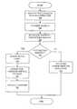
- FIG. 7is a flowchart of an exemplary process to automatically establish a connection for an unmatched packet according to an embodiment of the invention.
- FIG. 8is a functional block diagram of an exemplary convergence layer incorporated in a device according to an embodiment of the invention.
- reference numerals within the one hundred seriesare initially introduced in FIG. 1
- reference numerals in the two hundred seriesare initially introduced in FIG. 2
- reference numerals in the eight hundred seriese.g. 810 and 812
- FIG. 8reference numerals in the eight hundred series
- connection-oriented servicesbut particularly support the automatic creation or establishment of connections for packets which have no initial associated connections.
- this auto-connect serviceis provided in a power line communication network.
- FIG. 1is an exemplary diagram of a network 100 according to some embodiments of the invention.
- the networkhas portions of its data communication network segments 104 over power lines.
- Power line communicationPLC
- BPLbroadband over power line
- These power line networksinclude networks created by using electrical wirings, for example, in homes and buildings. Data communicated for example, include, but are not limited to, music, streaming videos, files, voice, databases, text files, control commands, and network keys.
- This exemplary network 100may also include other wired, e.g., Ethernet, or wireless networks.
- the exemplary network 100includes one centralized network (CN).
- a CNtypically includes a central network coordinator also called the central coordinator (CCO) 120 that controls network activities, such as network timing, bandwidth allocation, and security, e.g., authentication and key management.
- CCOcentral coordinator
- the CCOis initially the only device and station within the CN.
- the data communication network 100includes more than one centralized network, with each CN controlled by a CCO. When two or more CNs are available, these CNs may operate, for example, in the coordinated mode.
- a CCOis a station (STA) or device that typically controls the timing and resource, e.g., bandwidth allocation, of all stations within the centralized network.
- STAstation
- a CCOmay also control and schedule its own network activities. The role of the CCO, however, generally may be transferred from one STA to another, if needed or so desired.
- the CCOtransmits beacons to maintain the timing of the network.
- the CCOalso determines and may select or authorize the determined stations, which stations in the network, may access the channel at a given time.
- a CCOmay also coordinate with other CCOs in interfering neighbor networks to enable neighbor networks to coexist and share the same channel.
- stations 110 , 114 , 118 , 122that may be connected to this exemplary PLC network include devices such as monitors, TVs, VCRs, DVD player/recorders, other audiovisual devices, computers, game consoles, sound systems, information appliances, smart-home technology appliances, home audio equipment, or any other device that is PLC-enabled or compatible, or is able to communicate via the power lines.
- devicessuch as monitors, TVs, VCRs, DVD player/recorders, other audiovisual devices, computers, game consoles, sound systems, information appliances, smart-home technology appliances, home audio equipment, or any other device that is PLC-enabled or compatible, or is able to communicate via the power lines.
- power line networksfeatures of the present invention are also relevant to other networks; for example, but not limited to, wired or wireless networks, networks that have a centralized architecture with a central coordinator controlling the activities of the stations in the network, networks with a different network architecture and topology, or to other networks applying a different network protocol.
- the use of power line networks in exemplary configurationsis intended to aid in understanding the features of the several embodiments of the invention.
- the network 100may use time division multiplexing (TDM) as a method of multiple data streams sharing a signal according to time segments.
- TDMtime division multiplexing
- the networks of the present inventionmay also use other time-division multiplexing technology, e.g., orthogonal frequency-division or combinations and variations thereof.
- Other technologies supporting PLCe.g., orthogonal frequency-division multiplexing (OFDM), however, may also be used within the network and system.
- OFDMorthogonal frequency-division multiplexing
- a CCO 120manages the activities of stations within its centralized network using, for example, beacons.
- Beaconsare typically control messages that identify the frame configuration and the bandwidth (BW) assignments within a time frame to multiple networks and to stations within a given network.
- Beaconsare typically broadcasted by each CCO, e.g., as a multi-network broadcast, and are decoded by the stations within the network and, in some embodiments by the CCOs of neighbor networks. Beacons are also typically tagged or identified, such that stations within a network decode and follow the BW allocation of their own network beacon and not the beacon of another network. Beacons are also transmitted or broadcasted, typically periodically, into the networks.
- FIG. 2is an exemplary diagram of a beacon period for the exemplary network 100 according to an embodiment of the invention.
- a beacon periodcomprises several parts or regions. Each region is further typically defined into one or more time slots (e.g., 212 and 228 ). In some embodiments, a beacon period comprises four regions:
- a beacon region 210is the region wherein a CCO is able to transmit its own beacon.
- the beacon regiongenerally includes a plurality of a certain number of beacon or time slots, with the duration of each beacon slot typically sufficient for the transmission of a beacon.
- the duration of each beacon slotis equal to the sum of the duration of a beacon PHY protocol data unit (PPDU) and the interframe space.
- PPDUbeacon PHY protocol data unit
- a beacon region 210in some embodiments, consists of one to a maximum number—typically defined within the system of time slots or beacon slots.
- the size of the beacon region, including the number of time slotsmay be adjusted dynamically by the CCO.
- the CCO 120transmits its own beacon at beacon time slot BO 212 .
- Carrier Sense Multiple Access (CSMA) region or Contention Period (CP) RegionCSMA region or Contention Period (CP) Region:
- the CSMA region 230is a region wherein any one or more of many contention access protocols are used to share the medium and to coordinate network traffic.
- a CSMA/CA protocolmay be used.
- a networkmay have one or more CP or CSMA regions.
- the CSMA or CP regions of one centralized networkdo not overlap with the reserved or contention-free period regions of other networks. Communication, however, between two or more interfering networks may be made during overlapping CSMA regions.
- the reserved or CFP region 240is a period when only stations that have explicit authorization from the CCO are allowed to transmit.
- a reserved regionis a time interval that is typically reserved by a network. The network that has been allocated or has acquired control of the reserved region typically schedules the transmission of its contention-free links here.
- the CCOmay also schedule CSMA allocations that may be used only by the STAs in that network. For example, time slot 228 in the reserved region 240 has been allocated by the CCO to STA A 110 , so that STA A 110 may freely transmit at that time slot or interval 228 without interference, conflict, or contention from other stations 114 , 118 , 120 , 122 within the network.
- STA Amay freely transmit, while other stations in that network are typically silent.
- the CCOsends a message directly to the station informing that station when to transmit and sometimes even listen.
- a networkmay have any number of reserved regions in a beacon period.
- the stayout region 250is a period within the time frame when all stations assigned a stayout region are instructed by the CCO to remain silent, meaning no transmission. Typically, these stations are also not to use any contention access or contention-free access protocol.
- a stayout regionis assigned to avoid conflicts with a station or the network that has been assigned a reserved region in the same time interval.
- a networkspecifies a stayout region if one or more of the neighboring networks, typically defined for example within a network interfering list, have specified a reserved region or a protected region in the same time interval.
- the various types of regionsneed not be allocated in one contiguous time interval. This means for example, that the various types of regions may interleave each other, e.g., a time frame or beacon period includes a beacon region, followed by a CSMA region, followed by a stayout region, followed by another CSMA region, and then followed by a reserved region.
- the various regions within a beacon periodmay also be of varying sizes with varying number of time slot intervals or durations.
- the end time of each region type within a beacon periodis stored, for example, in multiples of a defined allocation time unit—e.g., 0.32 msec.
- a beacon periodmay include another region type (not shown) called a Protected Region.
- a CCOdetects the existence of another group, i.e., another CN or set of CNs with a different timing and if it optionally decides to coordinate with networks in that group, that CCO typically specifies a protected region in the same interval where the beacon region of the other group is located. Stations in a network typically are not allowed to transmit in a protected region.
- a neighboring group of networksmay have a different beacon period start time.
- the devices within a networkare able to share bandwidth using the same medium or channel, e.g. power line medium.
- the CCO in each networkthus typically controls BW allocation and scheduling within its network.
- the stations within the networkthus decode their own network beacons, and accordingly perform their functions, such as network transmission, following the beacon period allocations or schedule.
- a beacon periodmay contain zero or more of each of the regions described above, i.e., not all regions are present. In some other embodiments, there are more than one instance of any or all of the exemplary regions described above.
- FIG. 3is an exemplary protocol architecture of some embodiments of the present invention. These protocol layers may be associated with the Open System Interconnection (OSI) reference model.
- the lowest layeris the physical layer (PHY) 304 , which typically transmits and receives raw bits over a communication channel and encodes and/or decodes signals.
- PHYphysical layer
- MACmedia access control
- MACconvergence layer
- the CL 312is typically adapted to convert the service requirements of higher layer entities or applications 306 to the services offered by the lower layer entities 304 , 308 , 312 .
- the CL 312further provides a layer shielding higher-level applications 306 from the details or complexities of the MAC 308 and PHY 304 layers.
- the CL 312typically accepts data packets through service access points (SAPs), e.g., at an interface, and processes such packets prior to sending them off to the MAC layer through the M 1 interface.
- SAPsservice access points
- the functions of the CL 312may include, for example, mapping of higher layer control plane procedures to procedures supported by the lower layers or lower layer entities, encapsulating protocol date unit framing of upper layers into native MAC/PHY frames, mapping an upper layer address into an appropriate address, translating upper layer quality of service (QoS) parameters into native MAC format, and the like.
- QoSquality of service
- the higher layer entity or application 306may include Ethernet, Internet Protocol (IP), ATM, FIREWIRE, IEEE 1394, Universal Plug and Play (UPnP), IP applications, digital audio/video multicasts, digital telephony, control applications, bridges, and the like.
- IPInternet Protocol
- FIREWIREFireWire
- IEEE 1394FireWire
- UPFUniversal Plug and Play
- connection-oriented serviceprovides connection-oriented service.
- a connectionmay be either unidirectional, i.e., data flows in only one direction, or bidirectional, i.e., data flows in both directions.
- a forward directionmay be defined as the direction from the originating STA to the terminating STA and a reverse direction is the direction from the terminating STA to the originating STA.
- a forward linkis identified as originating at the STA that initiates the connection-establishment procedure and terminating on the station(s) responding to the connection establishment request.
- connectionsare used to provide guarantees on Quality of Service (QoS).
- Connection-oriented trafficmay use either the CFP or the CP/CSMA, typically depending on the QoS requirements of the connection.
- a connectionmay be composed of links.
- a linkis typically a unidirectional data flow, e.g., a packet or set of related packets, from typically the CL of the source of the link to the CL of one or more destinations of the link.
- Linksmay also be categorized as unicast or broadcast/multicast depending on the number of destinations of link.
- a connectionmay be composed of one of the following exemplary combinations of links:
- connections and linksare also connections.
- different types of linksmay be supported, e.g., a link controlled by the CCO 120 and those links controlled just by STAs 110 , 118 , 114 , 122 .
- connection specificationtypically contains the set of parameters that define the characteristics and QoS expectations of a connection.
- a CSPECis typically defined for each of the forward link and the reverse link.
- a unidirectional connectionmay specify only forward or reverse direction QoS requirements, depending on the direction in which the connection's data traffic flows.
- FIG. 4shows an exemplary system architecture showing the protocol layers in more detail and in conjunction with a CCO 120 .
- the connections for a STAare managed by a connection manager (CM) 402 .
- the CM 402in some embodiments functions as the control plane of the CL 312 .
- the CCO 120may also communicate with the connection manager (CM) 402 of a station. Between adjacent layers is typically an interface 418 , 414 , 412 , which defines which primitive operations and services the lower layer makes available to the upper or higher layer.
- local connectionsare managed by the CMs 402
- global connectionsare managed by the CCO.
- the CL 312includes the data plane between the H 1 interface 418 and the M 1 414 interface.
- the CL 312typically receives data packets from the data service access points (SAPs) on one interface, for example, Ethernet SAP 408 , processes the packets, including reformatting if appropriate, and directs the packets to the appropriate destination SAP on the other interface, e.g., an M 1 SAP (not shown).
- SAPsdata service access points
- Ethernet SAP 408processes the packets, including reformatting if appropriate, and directs the packets to the appropriate destination SAP on the other interface, e.g., an M 1 SAP (not shown).
- the CL 312automatically provides, if appropriate, connection service, for example, for packets from legacy applications that start transmission without specifying QoS parameters, packets bridged from another network, and for packets where the HLE 306 does not establish connections.
- connectionsare established with QoS CSPEC, even when the HLE does not establish the connection.
- devices within the networkmay be able to use CP or CFP time slots, for example, based on recognition of the application type or data-stream characteristics, thereby efficiently managing bandwidth allocation.
- the HLE 306communicates with the CL 312 through service access points (SAPs), e.g., Ethernet SAP, 408 at the H 1 interface 418 .
- SAPsservice access points
- the CL 312implements protocol adaptation layers (PAL) to service the SAPs and exchange data with the HLE.
- PALprotocol adaptation layers
- a control SAP 404is between the HLE 306 and the CM 402 .
- a control SAP 404typically enables the HLE 306 to create and manage connections, monitor status and statistics, support vendor-specific primitives, and initialize stations.
- An M 1 interface 414is between the CL 312 and the MAC layer 308 .
- a SAPis used by the CL to pass data received from the HLEs to the MAC 308 .
- a PHY interface 412is between the MAC layer 308 and the PHY layer 304 .
- FIG. 5is a block diagram of an exemplary convergence layer (CL) 312 , which includes the CM 402 functioning as the control plane.
- the exemplary embodiments of the CL 312 of the present inventionsupport the auto-connect service or features described herein.
- the CM 402includes an auto-connect service module (ACS) 512 and a rule configurator module 514 .
- the CL 312in general, may include a classifier module 504 , a demuxing module 516 , a QoS monitor module 520 , and a smoothing module 524 .
- the classifier 504is associated with a set of classifier rules 508 and operates on that set of rules to match packets.
- CM 402may be incorporated as part of the CL 312 .
- functions described hereinmay be distributed to other modules and/or combined with other modules.
- the various modules in the CL 312may interface with each other and may be combined.
- the smoothing module 524typically provides point-to-point smoothing, e.g., jitter control and delay compensation, with HLEs that request such a feature.
- point-to-point smoothinge.g., jitter control and delay compensation
- the terms “smoothing,” “delay compensation,” and “jitter control”refer to the smooth delivery of packets to the destination (rendering) application.
- Point-to-point smoothingmay be performed between two arbitrary points along the data path between the source and the destination. It is generally performed without awareness of or access to any timing information internal to the data stream.
- a classifier 504typically in the transmitter or transmitting device or station, maps or associates individual data packets, from various SAPs 530 , into corresponding connections, typically by using a set of classifier rules 508 .
- the classifier 504may receive incoming packets from the HLE or application 306 via a data SAP 530 .
- Each SAPmay have one or more associated classifiers.
- This set of classifier rules 508may contain a set of rules, e.g., parameters or information used by the classifier module 504 to detect individual streams of packets from all the packets that flow across the CL data SAPs.
- Each classifier rule 508may also include a rule priority and a connection identifier, e.g., a link ID (LID), with which the packet may be compared or matched.
- the classifier 504may also be adapted to use the rule priority parameter of each rule to determine the order in which the rules are to be applied to the packet. If a packet delivered to or received by the classifier 504 matches a classifier rule 508 , the received packet is then sent over or transferred to the referenced connection, e.g., indicated by a connection identifier, associated with that classifier rule.
- This set or sets of classifier rulesare typically local to each station and are not typically transmitted across the network. In some embodiments, several classifier rules may be associated with the same connection.
- a set of classifier rulesmay also indicate the source and destination MAC addresses and the TCP source and destination ports of the connection.
- the classifier rules 508are provided by the application or HLE 306 , or in the case of automatic connection establishment by the rule configurator module 514 .
- each received packetmay contain a connection identifier, e.g., an LID, and a temporary equipment identifier that uniquely identify the connection, and hence the SAP with which the connection is associated.
- certain operationsare performed when packets do not match any of the classifier rules. These unmatched packets may be assigned to a “best-effort” contention period traffic, processed by the ACS module 512 to automatically obtain an associated connection—auto-connect service, or be discarded. In some alternative embodiments, these operations may be identified as default rules and/or operations within a classifier.
- the auto-connect service (ACS) module 512typically determines and establishes connections for packets that the classifier is unable to match with its set of classifier rules.
- the ACS module 512may also detect data flows and may then establish, maintain, and teardown, if appropriate, connections with QoS for such data flows.
- the rule configurator module 514 of the CM 402typically manages the one or more classifiers 504 of the convergence layer 312 , including configuring and updating the classifiers with updated/new classifier rules 508 .
- the CM 402particularly the rule configurator module 514 , configures the classifier of the associated CL port for that connection with classification rules 508 .
- These rulesenable the classifier to map packets from the CL port to the appropriate LID or connection. If the classifier, however, is configured by the CM to report unmatched packets, the classifier may inform the CM, particularly the ACS module 512 , of any received unmatched packets, including those packets' destination MAC address and source CL port.
- Table I belowshows an exemplary classifier rule structure.
- the complexity of masking, bit manipulation, e.g., ANDing or ORing, and number of rules for matching purposesmay vary.
- the implementation for classifying packets to streamsmay also be performed.
- an exemplary embodimentmay have multiple audio visual (AV) data SAPs with each SAP associated with an individual connection.
- the classifier 504may easily determine the connection, e.g., via LID, of each packet by just determining the SAP from which the packet was received.
- Classification Parameter 1The first of the classification parameters . . . . . Classification Parameter N The last of the classification parameters
- Table IIshows an exemplary table for exemplary classifier rules for Ethernet II-Class Data SAP.
- TCPTransmission Control Protocol
- UDPUser Datagram Protocol
- the QoS monitor module 520typically gathers and monitors statistics and data traffic to confirm that the data transport service levels being delivered satisfy the guaranteed QoS service level.
- the QoS monitoring 520 capabilitiesmay be done by the transmitting and/or receiving station.
- FIG. 6is an exemplary state diagram showing how packets are processed according to some embodiments of the invention.
- a packet 604is received by a classifier 504 from a higher layer entity or application 306 , typically via an appropriate SAP.
- This incoming packet 604is then processed by the classifier 504 to determine if the packet matches any of its classifier rules. If the processed packet matches a classifier rule 608 , the classifier 504 then associates or maps such packet from the CL port to the appropriate LID or connection 610 based on the matched rule. Alternatively, if the received packet does not match any of the classifier rules, this unmatched packet 612 is sent to the ACS module 512 .
- the classifier 504may also send the ACS 512 a “no match” notification indicating that the packet is unmatched by the classifier. In some embodiments, this “no match” indication may be provided by transmitting the unmatched packet to the ACS. In some embodiments, the ACS may be presented with every data packet delivered to the H 1 interface that is not part of any established connection, i.e., not matched by the classifier. In some embodiments, only portions of such data packets are sent to the ACS 512 .
- the ACS 512may receive varying kinds of packets to evaluate and to establish connection(s), if appropriate.
- packetsmay include streamed packets for which transport in the CFP is appropriate, real-time transport protocol (RTP) packets for which either CFP or CP transport may be appropriate, prioritized packets for which either CFP or CP transport (either connection-oriented or connectionless) may be appropriate, and common packets for which connectionless CP transport is appropriate.
- RTPreal-time transport protocol
- the ACS 512Upon receipt of the unmatched packet, the ACS 512 then examines 630 the packet, for example, reading the packet and determining information stored and carried in the packet. The ACS 512 also typically releases the examined packets 626 for connectionless transport in CP/CSMA 620 after such examination. Typically, the ACS 512 does not hold packets while the ACS is determining whether a connection is warranted or while a connection is being established.
- the ACS 512also evaluates the packet 622 to determine if the packet is connection worthy. Such evaluation may include evaluating whether connection-oriented service is appropriate for the packet sequence of which the current packet may be a part—“connection worthy,” or whether the packet is to be transported via connectionless service. If the packet is determined to be not connection worthy, the packet is sent for connectionless traffic, e.g., best effort 640 . The decision about the manner in which packet(s) are to be transported may be based on one or more of the following:
- the number of packets the ACS may examine to determine whether the packets are part of a “connection worthy” data flowmay depend on the method used for determination. If templates and/or policies are used, the ACS may be able to determine connection-worthiness from a single packet. If heuristics, however, are used, the ACS may need to examine multiple packets to determine how fast packets are arriving and how much bandwidth would be required for a connection.
- the ACS 512determines that the incoming or received unmatched packet is connection worthy, the ACS 512 initiates the connection establishment process and specifies a connection specification for that packet 634 .
- the rule configurator module 514updates the classifier with the appropriate rules 628 , including connection identifiers, so future packets may be appropriately processed by the classifier.
- the ACS module 512may also manage the connections it establishes, including reconfiguration and teardown, which the HLE would normally perform. In this embodiment, the capabilities of connection reconfiguration and connection teardown are also available for the ACS module 512 .
- implementers of the features of the present inventionmay establish controls internal to the control plane to enable the ACS to have access to the same capabilities as an HLE, including awareness of the data flow of the connections that the ACS establishes.
- the ACSmay establish an initial CSPEC, similar to the process, for example, performed by the HLE when establishing a connection. While connections requested by an HLE are connections between HLEs, connections established by ACS are typically not. The difference is whether the connection is negotiated between HLEs or between CLs. Typically, connections established by the ACS are negotiated between the CLs of the source and destination devices. To ensure that the HLE is not notified of the events triggered by the establishing or maintenance of automatic connections, connections established by ACS may be indicated as such, for example, via a parameter field, and the CL 312 typically does not communicate connection-related primitives to the HLE for connections made by the ACS
- the ACSmay also be responsible for performing activities that would normally be undertaken by the HLE, including management, reconfiguration, and teardown of the connections it establishes.
- the ACSmay be responsible for:
- This monitoring of automatic connections performed by the ACSdiffers from the monitoring performed by the convergence layer, in general.
- CL monitoringis to ensure that service level matches that guaranteed by the CSPEC.
- ACS monitoring for connections automatically establishedis to ensure that QoS levels established in the CSPEC generated by ACS are appropriate for the data traffic carried by the automatic connection.
- a connectionis created by the ACS by initiating a messaging sequence to set up the connection.
- the ACS or the CM 402may determine how many links are required and whether each link should be a global link or local link.
- the CM 402particularly the ACS 512 , may then communicate with the CM or the ACS of the destination station, and possibly with the CCO 120 , to establish the one or more links to establish or create the connection.
- the ACS 512is responsible for monitoring if the generated CSPEC is appropriate. If a link or connection is not performing according to its CSPEC, the ACS 512 typically initiates a link reconfiguration with a new CSPEC or it may tear down the connection.
- the connectionmay be between more than two stations. Each of these connections may have either global or local links along with its own, possibly unique, CSPEC.
- global linksare established and controlled by the CCO 120 at the request of an ACS 512 .
- the source STA and the destination STAmay request sufficient BW from the CCO to guarantee QoS.
- the CCOtypically assigns the global link a dedicated BW allocation and a global link ID (GLID) that is typically unique in a network.
- GLIDglobal link ID
- the global linkmay be identified by the Connection ID (CID) assigned by the ACS that initiated the connection.
- CIDConnection ID
- each connection requestedis associated with a CID.
- a global linkis managed globally by the CCO and locally by the CMs, particularly the ACS for auto-connect services, on each of the STAs involved in the connection.
- a global linkmay be used in contention-free and contention traffic.
- a GLIDmay also be used to identify different types of allocation. For contention-free allocation, for example, the GLID or another field may be used to identify the unique link that may use the medium.
- FIG. 7shows a flowchart of an exemplary auto-connect service feature of the present invention.
- the ACSis initiated by receiving data packets with no associated connection (step 704 ).
- the ACSthen examines the packet to extract or determine information contained in the packet (step 706 ).
- the packetis then typically immediately released for connectionless traffic.
- the ACSdetermines whether the unmatched packet or packets are entitled to a connection, i.e., whether each is “connection worthy” (step 708 ). If the ACS determines that the data packet(s) are not connection worthy (decision 710 ), the packets are typically released immediately for connectionless transport (step 732 ).
- the packetsare released for connectionless service transport in the contention period or carrier sense multiple access (CSMA) traffic as soon as the ACS finishes examining or reading the packet.
- CSMAcarrier sense multiple access
- the ACSestablishes an initial CSPEC (step 720 ).
- the CSPECtypically defines the connection requirements.
- the ACStypically follows the same process performed by an application for establishing the connection.
- a connection-oriented serviceis then typically invoked, e.g., by initiating a connection set-up process with the appropriate device or station (step 724 ), and the classifier updated (step 728 ), typically with new classifier rules, so that future packets are handled correctly by the classifier without invoking the ACS process again.
- the ACSgenerally no longer processes those packets types because the classifier is routing them to the new connection based on the new rules.
- FIG. 8is a high-level functional block diagram of an exemplary device 800 incorporating the auto-connect service features, according to some embodiments of the invention.
- This exemplary device 800may include an I/O interface 810 , a rule configurator module 804 , an auto-connect service module 808 , a classifier module 812 , a QoS monitor module 832 , and other station modules, such as a demuxing module, a smoothing module, and the like.
- the exemplary device 800may also include a memory, which may be volatile or non-volatile, for example, for storing the classifier rules used by the classier module 812 to classify packets into appropriate connections, if available.
- the I/O interface 810typically enables the device 800 to communicate with other devices within the network.
- the rule configurator module 804performs the functions described above, particularly updating the classifier rules used by the classifier module.
- the ACS module 808performs the auto-connect features described above, in particular, examining or reading the packets, determining whether packets are connection worthy, establishing appropriate CSPECs for connection worthy packets, monitoring that the CSPECs generated by the ACS are appropriate for the data traffic carried by the automatic connections, and managing, reconfiguring, and tearing down automatic connections established by the ACS.
- Connection reconfigurationmay occur when the CSPEC parameters of the connection have changed.
- Connection teardownsmay be initiated when one or more violations of the CSPEC occur for those automatic connections. In some embodiments, teardowns may be invoked if requested.
- the ACSnegotiates with the other station for reconfiguration, which may typically involve changes to the CSPEC parameters, allocation changes, and a modification to the automatic connection.
- the classifier module 812generally classifies incoming packets from HLEs or applications by matching the packets or data flow to the appropriate connections, if appropriate.
- the QoS monitor module 832monitors that the service level of the CL in general matches that which is guaranteed or defined within the CSPEC.
- the QoS monitor module 832thus typically continuously monitors existing connections, including links, for adherence to the negotiated traffic characteristics (traffic policing) and QoS guarantees.
Landscapes
- Engineering & Computer Science (AREA)
- Computer Networks & Wireless Communication (AREA)
- Signal Processing (AREA)
- Power Engineering (AREA)
- Databases & Information Systems (AREA)
- Mobile Radio Communication Systems (AREA)
- Data Exchanges In Wide-Area Networks (AREA)
- Small-Scale Networks (AREA)
Abstract
Description
- 1. A single unicast forward link from the station that initiated the connection to the terminating station of the connection;
- 2. A single unicast reverse link from the terminating station of a connection to the initiating station of the connection;
- 3. Both (1) and (2)—i.e., a bi-directional connection; and
- 4. A single multicast/broadcast link from the station that initiated the connection to the terminating stations of the connection.
| TABLE I |
| Exemplary Classifier Rule Structure |
| Field Name | Description |
| LID | Link ID or Connection Identifier |
| Priority | Rule Priority |
| Number of Classification | The count of classification parameters that |
| Parameters | follow. Each classification parameter typically |
| has a unique identifier and parameters that | |
| define the match criteria for that parameter. | |
| Classification Parameter 1 | The first of the classification parameters |
| . . . | . . . |
| Classification Parameter N | The last of the classification parameters |
| Name | Values | |
| Ethernet II | Destination MAC | DstValue, DstMask. A match occurs |
| address | when the DstValue = ([the packet's | |
| destination MAC address] AND | ||
| DstMask) | ||
| Source MAC | SrcValue, SrcMask. A match occurs | |
| address | when the SrcValue = ([the packet's | |
| source IP address] AND SrcMask) | ||
| FrameType | The Ethernet Type field | |
| IEEE802.1Q | UserPriority | |
| VLAN ID | ||
| IPv4 | IP Source address | SrcValue, SrcMask. A match occurs |
| when the SrcValue = ([the packet's | ||
| source IP address] AND SrcMask) | ||
| IP Destination | DstValue, DstMask. A match occurs | |
| address | when the DstValue = ([the packet's | |
| destination IP address] AND | ||
| DstMask) | ||
| IP Protocol | Protocol number (0 . . . 65535) | |
| IP Type of Service | High, Low, Mask. A match occurs | |
| when Low <= ([the packet's IPv4 | ||
| Type of Service] AND Mask) <= | ||
| High | ||
| IPv6 | IPv6Source address | SrcValue, SrcMask. A match occurs |
| when the SrcValue = ([the packet's | ||
| source IP address] AND SrcMask) | ||
| IPv6Destination | DstValue, DstMask. A match occurs | |
| address | when the DstValue = ([the packet's | |
| destination IP address] AND | ||
| DstMask) | ||
| IPv6Protocol Type | Protocol number (0 . . . 65535) | |
| in Next Header | ||
| IPv6 Traffic Class | High, Low, Mask. A match occurs | |
| when Low <= ([the packet's IPv4 | ||
| Type of Service] AND Mask) <= | ||
| High | ||
| IPv6Flow Label | High, Low, Mask. A match occurs | |
| when Low <= ([the packet's IPv6 | ||
| Flow Label] AND Mask) <= High | ||
| TCP and UDP | IP Source Port | SrcPort, SrcMask. A match occurs |
| when the SrcPort = ([the packet's | ||
| source IP port] AND SrcMask) | ||
| IP Destination Port | DstPort, DstMask. A match occurs | |
| when the DstPort = ([the packet's | ||
| destination IP port] AND DstMask) | ||
- IPv6 Header+Next Header=Routing;
- Routing Header+Next Header=Fragment;
- Fragment Header+Next Header=TCP,
- TCP Header+TCP data
- a) Policies established for identifying automatic connections, e.g., established by an HLE or application;
- b) Templates: providing certain default rules; e.g., associating traffic on a particular IP port with a particular usage, thereby implying a level of QoS from that usage; and
- c) Heuristics: attempting to identify a need for a particular level of QoS from the statistical behavior of traffic offered. For example, the ACS may monitor successive packets and judge whether they are streaming data (i.e., whether the packets should be transferred with reserved bandwidth channel). If it judges streaming data, the ACS may decide on the appropriate QoS parameters and establish a connection. Such heuristics may also be based, for example, on the volume and regularity of data which is being transmitted.
- a) Monitoring the data flow;
- b) Ensuring that the initial CSPEC it assigned is appropriate for the data flow; and
- c) Making the appropriate adjustments to that CSPEC.
Claims (20)
Priority Applications (4)
| Application Number | Priority Date | Filing Date | Title |
|---|---|---|---|
| US11/388,584US8027345B2 (en) | 2005-07-27 | 2006-03-24 | Method for automatically providing quality of service |
| JP2006202448AJP2007037139A (en) | 2005-07-27 | 2006-07-25 | Method for automatically providing quality of service (QoS) |
| EP06015624AEP1748606B1 (en) | 2005-07-27 | 2006-07-26 | Method for automatically providing quality of service |
| DE602006007520TDE602006007520D1 (en) | 2005-07-27 | 2006-07-26 | Method for automatic delivery of service quality |
Applications Claiming Priority (2)
| Application Number | Priority Date | Filing Date | Title |
|---|---|---|---|
| US70338105P | 2005-07-27 | 2005-07-27 | |
| US11/388,584US8027345B2 (en) | 2005-07-27 | 2006-03-24 | Method for automatically providing quality of service |
Publications (2)
| Publication Number | Publication Date |
|---|---|
| US20070025243A1 US20070025243A1 (en) | 2007-02-01 |
| US8027345B2true US8027345B2 (en) | 2011-09-27 |
Family
ID=37057199
Family Applications (1)
| Application Number | Title | Priority Date | Filing Date |
|---|---|---|---|
| US11/388,584Expired - Fee RelatedUS8027345B2 (en) | 2005-07-27 | 2006-03-24 | Method for automatically providing quality of service |
Country Status (4)
| Country | Link |
|---|---|
| US (1) | US8027345B2 (en) |
| EP (1) | EP1748606B1 (en) |
| JP (1) | JP2007037139A (en) |
| DE (1) | DE602006007520D1 (en) |
Cited By (1)
| Publication number | Priority date | Publication date | Assignee | Title |
|---|---|---|---|---|
| US12238009B1 (en)* | 2023-10-05 | 2025-02-25 | Oracle International Corporation | Distributed rate limiting |
Families Citing this family (16)
| Publication number | Priority date | Publication date | Assignee | Title |
|---|---|---|---|---|
| US8010685B2 (en)* | 2004-11-09 | 2011-08-30 | Cisco Technology, Inc. | Method and apparatus for content classification |
| US7936682B2 (en)* | 2004-11-09 | 2011-05-03 | Cisco Technology, Inc. | Detecting malicious attacks using network behavior and header analysis |
| US7535909B2 (en) | 2004-11-09 | 2009-05-19 | Cisco Technology, Inc. | Method and apparatus to process packets in a network |
| US7768916B2 (en)* | 2005-11-14 | 2010-08-03 | Cisco Technology, Inc. | Use of negative classifiers for Internet traffic |
| KR100684326B1 (en)* | 2005-11-22 | 2007-02-16 | 한국전자통신연구원 | Apparatus and method for classifying service quality of IP packet in portable Internet system |
| US20090116505A1 (en)* | 2007-11-07 | 2009-05-07 | Alcatel Lucent | Service Based VLAN Stacking |
| US8761022B2 (en) | 2007-12-26 | 2014-06-24 | Rockstar Consortium Us Lp | Tie-breaking in shortest path determination |
| US7911944B2 (en)* | 2007-12-26 | 2011-03-22 | Nortel Networks Limited | Tie-breaking in shortest path determination |
| FR2927753A1 (en)* | 2008-02-20 | 2009-08-21 | France Telecom | METHOD AND DEVICE FOR CONTROLLING THE QUALITY OF SERVICE IN A NETWORK. |
| US8306055B2 (en) | 2009-12-24 | 2012-11-06 | Intel Corporation | Method and system to support wireless multicast transmission |
| US8539028B2 (en)* | 2010-11-05 | 2013-09-17 | Logmein, Inc. | Network-based quick connect meeting service |
| CN102833165B (en)* | 2012-08-27 | 2015-06-17 | 华为技术有限公司 | Method and device for dispatching resources |
| US9762496B2 (en)* | 2014-02-25 | 2017-09-12 | Qualcomm Incorporated | Slotted message access protocol for powerline communication networks |
| US9848330B2 (en)* | 2014-04-09 | 2017-12-19 | Microsoft Technology Licensing, Llc | Device policy manager |
| CN111669362B (en) | 2014-06-09 | 2022-04-08 | 华为技术有限公司 | Information processing method, network node, verification method and server |
| GB2580285B (en)* | 2018-08-13 | 2021-01-06 | Metaswitch Networks Ltd | Packet processing graphs |
Citations (56)
| Publication number | Priority date | Publication date | Assignee | Title |
|---|---|---|---|---|
| US4977593A (en) | 1987-11-27 | 1990-12-11 | British Telecommunications Plc | Optical communications network |
| US5142578A (en) | 1991-08-22 | 1992-08-25 | International Business Machines Corporation | Hybrid public key algorithm/data encryption algorithm key distribution method based on control vectors |
| US5185796A (en) | 1991-05-30 | 1993-02-09 | Motorola, Inc. | Encryption synchronization combined with encryption key identification |
| US5204903A (en) | 1990-11-05 | 1993-04-20 | Nippon Telegraph And Telephone Corporation | Secure communication equipment and secure transmission system |
| US5887063A (en) | 1995-07-28 | 1999-03-23 | Hewlett-Packard Company | Communication system for portable appliances |
| US5987331A (en) | 1996-11-20 | 1999-11-16 | Motorola, Inc. | Communication system to communication system gateway method and apparatus |
| US6097817A (en) | 1997-12-10 | 2000-08-01 | Omnipoint Corporation | Encryption and decryption in communication system with wireless trunk |
| US20010048692A1 (en) | 2000-04-10 | 2001-12-06 | Bernd Karner | Method for network medium access control |
| US20020116342A1 (en) | 2001-02-20 | 2002-08-22 | Yasuhiro Hirano | Domestic electrical apparatus, subscriber registering method, order receiving method, and data processing system |
| US20020150249A1 (en) | 2001-03-27 | 2002-10-17 | Hideki Ohkita | Communication apparatus |
| US20020163933A1 (en) | 2000-11-03 | 2002-11-07 | Mathilde Benveniste | Tiered contention multiple access (TCMA): a method for priority-based shared channel access |
| EP0844563B1 (en) | 1996-11-19 | 2003-01-29 | R. Brent Johnson | Combined remote access and security system |
| WO2003015291A2 (en) | 2001-08-04 | 2003-02-20 | Enikia Llc | Frequency management and policing |
| US6526581B1 (en) | 1999-08-03 | 2003-02-25 | Ucentric Holdings, Llc | Multi-service in-home network with an open interface |
| US20030039257A1 (en) | 2001-08-04 | 2003-02-27 | Manis Constantine N. | Network-to-network adaptor for power line communications |
| US20030051146A1 (en) | 2001-09-11 | 2003-03-13 | Akihiro Ebina | Security realizing system in network |
| US20030056014A1 (en) | 2001-07-10 | 2003-03-20 | Verberkt Mark Henricus | Gateway for interconnecting networks |
| WO2003026224A1 (en) | 2001-09-15 | 2003-03-27 | Koninklijke Philips Electronics N.V. | Network with several subnetwoks |
| US20030066082A1 (en) | 2000-08-30 | 2003-04-03 | Avi Kliger | Home network system and method |
| US6559757B1 (en) | 2000-10-26 | 2003-05-06 | Home Tough Lighting Systems Llc | Data communication over power lines |
| US6587453B1 (en) | 1997-12-17 | 2003-07-01 | Hewlett-Packard Company | Method of communicating first and second data types |
| US6594268B1 (en)* | 1999-03-11 | 2003-07-15 | Lucent Technologies Inc. | Adaptive routing system and method for QOS packet networks |
| US20030198246A1 (en) | 2002-04-23 | 2003-10-23 | Israel Lifshitz | Adaptive synchronous media access protocol for shared media networks |
| US20030203716A1 (en) | 2002-04-26 | 2003-10-30 | Kabushiki Kaisha Kobe Seiko Sho(Kobe Steel, Ltd.) | Wireless data collecting system and wireless data relay apparatus |
| US20030231607A1 (en) | 2002-05-30 | 2003-12-18 | Scanlon Williamgiles | Wireless network medium access control protocol |
| US20040013135A1 (en) | 2002-07-17 | 2004-01-22 | Yoram Haddad | System and method for scheduling traffic in wireless networks |
| US20040066783A1 (en)* | 2002-09-26 | 2004-04-08 | Deepak Ayyagari | Connection management in a centralized communication system |
| US20040077345A1 (en)* | 2002-08-02 | 2004-04-22 | Turner R. Brough | Methods and apparatus for network signal aggregation and bandwidth reduction |
| US20040075535A1 (en) | 1999-12-02 | 2004-04-22 | Propp Michael B | Power line communication network |
| US6759946B2 (en) | 2001-12-06 | 2004-07-06 | Mitsubishi Electric Research Laboratories, Inc. | Home appliances network |
| US6775280B1 (en) | 1999-04-29 | 2004-08-10 | Cisco Technology, Inc. | Methods and apparatus for routing packets using policy and network efficiency information |
| US6782476B1 (en) | 1998-06-16 | 2004-08-24 | Kabushiki Kaisha Toshiba | Data processing apparatus and authentication method applied to the apparatus |
| US20040165728A1 (en) | 2003-02-22 | 2004-08-26 | Hewlett-Packard Development Company, L.P. | Limiting service provision to group members |
| US20040174829A1 (en) | 2003-03-03 | 2004-09-09 | Sharp Laboratories Of America, Inc. | Centralized network organization and topology discovery in AD-HOC network with central controller |
| US6807146B1 (en) | 2000-04-21 | 2004-10-19 | Atheros Communications, Inc. | Protocols for scalable communication system using overland signals and multi-carrier frequency communication |
| US20040214570A1 (en) | 2003-04-28 | 2004-10-28 | Junbiao Zhang | Technique for secure wireless LAN access |
| US20040253996A1 (en) | 2003-06-12 | 2004-12-16 | Industrial Technology Research Institute | Method and system for power-saving in a wireless local area network |
| US20050015805A1 (en) | 2003-07-17 | 2005-01-20 | Sony Corporation | Power line home network |
| US20050033960A1 (en) | 2001-02-12 | 2005-02-10 | Jukka Vialen | Message authentication |
| US20050041673A1 (en) | 2003-08-20 | 2005-02-24 | Frances Jiang | Method of managing wireless network resources to gateway devices |
| US6901064B2 (en) | 2002-01-10 | 2005-05-31 | Harris Corporation | Method and device for establishing communication links and detecting interference between mobile nodes in a communication system |
| US20050149757A1 (en) | 2004-01-07 | 2005-07-07 | Microsoft Corporation | System and method for providing secure network access |
| WO2005062546A1 (en) | 2003-12-24 | 2005-07-07 | Huawei Technologies Co., Ltd. | A method for achieving the conversion and traverse of network address and system thereof |
| US20050170835A1 (en) | 2003-11-07 | 2005-08-04 | Sharp Laboratories Of America, Inc. | Systems and methods for network coordination with limited explicit message exchange |
| US20050174950A1 (en) | 2004-02-09 | 2005-08-11 | Sharp Laboratories Of America, Inc. | Distributed network organization and topology discovery in ad-hoc network |
| US6934249B1 (en)* | 1997-04-01 | 2005-08-23 | Cisco Technology, Inc. | Method and system for minimizing the connection set up time in high speed packet switching networks |
| US20050243765A1 (en) | 2003-07-25 | 2005-11-03 | Schrader Mark E | Mesh network and piconet work system and method |
| US20060007907A1 (en) | 2004-07-10 | 2006-01-12 | Huai-Rong Shao | Beacon scheduling in wireless personal area networks with multiple coordinators |
| US20060031477A1 (en) | 2004-08-06 | 2006-02-09 | Sharp Laboratories Of America, Inc. | Ad hoc network with proxy networking |
| US7200147B2 (en) | 2001-11-23 | 2007-04-03 | Electronics And Telecommunications Research Institute | Method for analyzing address for next generation integrated network service |
| US7212513B2 (en) | 2001-11-01 | 2007-05-01 | Seiko Epson Corporation | Station for wireless network |
| US7242932B2 (en) | 2000-05-17 | 2007-07-10 | Motorola, Inc. | Mobile internet protocol on a signaling channel |
| US7330457B2 (en) | 2004-10-07 | 2008-02-12 | Polytechnic University | Cooperative wireless communications |
| US7356010B2 (en) | 2002-12-02 | 2008-04-08 | Ntt Docomo Inc. | Point coordinator control passing scheme using a scheduling information parameter set for an IEEE 802.11 wireless local area network |
| US7496078B2 (en) | 2006-08-15 | 2009-02-24 | Cisco Technology, Inc. | Route tree building in a wireless mesh network |
| US20090238153A1 (en) | 2004-12-20 | 2009-09-24 | Matsushita Electric Industrial Co., Ltd. | Medium access for de-centralized wireless network |
Family Cites Families (1)
| Publication number | Priority date | Publication date | Assignee | Title |
|---|---|---|---|---|
| GB9621248D0 (en)* | 1996-10-11 | 1996-11-27 | Univ Cambridge Tech | Switching system |
- 2006
- 2006-03-24USUS11/388,584patent/US8027345B2/ennot_activeExpired - Fee Related
- 2006-07-25JPJP2006202448Apatent/JP2007037139A/enactivePending
- 2006-07-26EPEP06015624Apatent/EP1748606B1/ennot_activeNot-in-force
- 2006-07-26DEDE602006007520Tpatent/DE602006007520D1/enactiveActive
Patent Citations (62)
| Publication number | Priority date | Publication date | Assignee | Title |
|---|---|---|---|---|
| US4977593A (en) | 1987-11-27 | 1990-12-11 | British Telecommunications Plc | Optical communications network |
| US5204903A (en) | 1990-11-05 | 1993-04-20 | Nippon Telegraph And Telephone Corporation | Secure communication equipment and secure transmission system |
| US5185796A (en) | 1991-05-30 | 1993-02-09 | Motorola, Inc. | Encryption synchronization combined with encryption key identification |
| US5142578A (en) | 1991-08-22 | 1992-08-25 | International Business Machines Corporation | Hybrid public key algorithm/data encryption algorithm key distribution method based on control vectors |
| US5887063A (en) | 1995-07-28 | 1999-03-23 | Hewlett-Packard Company | Communication system for portable appliances |
| EP0844563B1 (en) | 1996-11-19 | 2003-01-29 | R. Brent Johnson | Combined remote access and security system |
| US5987331A (en) | 1996-11-20 | 1999-11-16 | Motorola, Inc. | Communication system to communication system gateway method and apparatus |
| US6934249B1 (en)* | 1997-04-01 | 2005-08-23 | Cisco Technology, Inc. | Method and system for minimizing the connection set up time in high speed packet switching networks |
| US6097817A (en) | 1997-12-10 | 2000-08-01 | Omnipoint Corporation | Encryption and decryption in communication system with wireless trunk |
| US6587453B1 (en) | 1997-12-17 | 2003-07-01 | Hewlett-Packard Company | Method of communicating first and second data types |
| US6782476B1 (en) | 1998-06-16 | 2004-08-24 | Kabushiki Kaisha Toshiba | Data processing apparatus and authentication method applied to the apparatus |
| US6594268B1 (en)* | 1999-03-11 | 2003-07-15 | Lucent Technologies Inc. | Adaptive routing system and method for QOS packet networks |
| US6775280B1 (en) | 1999-04-29 | 2004-08-10 | Cisco Technology, Inc. | Methods and apparatus for routing packets using policy and network efficiency information |
| US6526581B1 (en) | 1999-08-03 | 2003-02-25 | Ucentric Holdings, Llc | Multi-service in-home network with an open interface |
| US20040075535A1 (en) | 1999-12-02 | 2004-04-22 | Propp Michael B | Power line communication network |
| US20010048692A1 (en) | 2000-04-10 | 2001-12-06 | Bernd Karner | Method for network medium access control |
| US6807146B1 (en) | 2000-04-21 | 2004-10-19 | Atheros Communications, Inc. | Protocols for scalable communication system using overland signals and multi-carrier frequency communication |
| US7242932B2 (en) | 2000-05-17 | 2007-07-10 | Motorola, Inc. | Mobile internet protocol on a signaling channel |
| US20030066082A1 (en) | 2000-08-30 | 2003-04-03 | Avi Kliger | Home network system and method |
| US6559757B1 (en) | 2000-10-26 | 2003-05-06 | Home Tough Lighting Systems Llc | Data communication over power lines |
| US20020163933A1 (en) | 2000-11-03 | 2002-11-07 | Mathilde Benveniste | Tiered contention multiple access (TCMA): a method for priority-based shared channel access |
| US20050033960A1 (en) | 2001-02-12 | 2005-02-10 | Jukka Vialen | Message authentication |
| US20020116342A1 (en) | 2001-02-20 | 2002-08-22 | Yasuhiro Hirano | Domestic electrical apparatus, subscriber registering method, order receiving method, and data processing system |
| US20020150249A1 (en) | 2001-03-27 | 2002-10-17 | Hideki Ohkita | Communication apparatus |
| US20030056014A1 (en) | 2001-07-10 | 2003-03-20 | Verberkt Mark Henricus | Gateway for interconnecting networks |
| US20030038710A1 (en) | 2001-08-04 | 2003-02-27 | Manis Constantine N. | Frequency management and policing |
| WO2003015291A2 (en) | 2001-08-04 | 2003-02-20 | Enikia Llc | Frequency management and policing |
| US20030039257A1 (en) | 2001-08-04 | 2003-02-27 | Manis Constantine N. | Network-to-network adaptor for power line communications |
| US20030051146A1 (en) | 2001-09-11 | 2003-03-13 | Akihiro Ebina | Security realizing system in network |
| WO2003026224A1 (en) | 2001-09-15 | 2003-03-27 | Koninklijke Philips Electronics N.V. | Network with several subnetwoks |
| US7212513B2 (en) | 2001-11-01 | 2007-05-01 | Seiko Epson Corporation | Station for wireless network |
| US7200147B2 (en) | 2001-11-23 | 2007-04-03 | Electronics And Telecommunications Research Institute | Method for analyzing address for next generation integrated network service |
| US6759946B2 (en) | 2001-12-06 | 2004-07-06 | Mitsubishi Electric Research Laboratories, Inc. | Home appliances network |
| US6901064B2 (en) | 2002-01-10 | 2005-05-31 | Harris Corporation | Method and device for establishing communication links and detecting interference between mobile nodes in a communication system |
| US20030198246A1 (en) | 2002-04-23 | 2003-10-23 | Israel Lifshitz | Adaptive synchronous media access protocol for shared media networks |
| US20030203716A1 (en) | 2002-04-26 | 2003-10-30 | Kabushiki Kaisha Kobe Seiko Sho(Kobe Steel, Ltd.) | Wireless data collecting system and wireless data relay apparatus |
| US20030231607A1 (en) | 2002-05-30 | 2003-12-18 | Scanlon Williamgiles | Wireless network medium access control protocol |
| US20040013135A1 (en) | 2002-07-17 | 2004-01-22 | Yoram Haddad | System and method for scheduling traffic in wireless networks |
| US20040077345A1 (en)* | 2002-08-02 | 2004-04-22 | Turner R. Brough | Methods and apparatus for network signal aggregation and bandwidth reduction |
| US20040066783A1 (en)* | 2002-09-26 | 2004-04-08 | Deepak Ayyagari | Connection management in a centralized communication system |
| US7356010B2 (en) | 2002-12-02 | 2008-04-08 | Ntt Docomo Inc. | Point coordinator control passing scheme using a scheduling information parameter set for an IEEE 802.11 wireless local area network |
| US20040165728A1 (en) | 2003-02-22 | 2004-08-26 | Hewlett-Packard Development Company, L.P. | Limiting service provision to group members |
| US7342896B2 (en) | 2003-03-03 | 2008-03-11 | Sharp Laboratories Of America, Inc. | Centralized network organization and topology discover in Ad-Hoc network with central controller |
| US20040174829A1 (en) | 2003-03-03 | 2004-09-09 | Sharp Laboratories Of America, Inc. | Centralized network organization and topology discovery in AD-HOC network with central controller |
| US20040214570A1 (en) | 2003-04-28 | 2004-10-28 | Junbiao Zhang | Technique for secure wireless LAN access |
| US20040253996A1 (en) | 2003-06-12 | 2004-12-16 | Industrial Technology Research Institute | Method and system for power-saving in a wireless local area network |
| US20050015805A1 (en) | 2003-07-17 | 2005-01-20 | Sony Corporation | Power line home network |
| US20050243765A1 (en) | 2003-07-25 | 2005-11-03 | Schrader Mark E | Mesh network and piconet work system and method |
| US20050041673A1 (en) | 2003-08-20 | 2005-02-24 | Frances Jiang | Method of managing wireless network resources to gateway devices |
| US20050170835A1 (en) | 2003-11-07 | 2005-08-04 | Sharp Laboratories Of America, Inc. | Systems and methods for network coordination with limited explicit message exchange |
| US20050169222A1 (en) | 2003-11-07 | 2005-08-04 | Sharp Laboratories Of America, Inc. | Methods and systems for network coordination |
| US20050193116A1 (en) | 2003-11-07 | 2005-09-01 | Sharp Laboratories Of America, Inc. | Method for transitioning between coordination modes for interfering neighbor networks |
| WO2005062546A1 (en) | 2003-12-24 | 2005-07-07 | Huawei Technologies Co., Ltd. | A method for achieving the conversion and traverse of network address and system thereof |
| EP1693998A1 (en) | 2003-12-24 | 2006-08-23 | Huawei Technologies Co., Ltd. | A method for achieving the conversion and traverse of network address and system thereof |
| US20050149757A1 (en) | 2004-01-07 | 2005-07-07 | Microsoft Corporation | System and method for providing secure network access |
| US20050174950A1 (en) | 2004-02-09 | 2005-08-11 | Sharp Laboratories Of America, Inc. | Distributed network organization and topology discovery in ad-hoc network |
| US20060007907A1 (en) | 2004-07-10 | 2006-01-12 | Huai-Rong Shao | Beacon scheduling in wireless personal area networks with multiple coordinators |
| US20060031477A1 (en) | 2004-08-06 | 2006-02-09 | Sharp Laboratories Of America, Inc. | Ad hoc network with proxy networking |
| US7506042B2 (en) | 2004-08-06 | 2009-03-17 | Sharp Laboratories Of America, Inc. | Hierarchical ad hoc network organizational method involving with proxy networking |
| US7330457B2 (en) | 2004-10-07 | 2008-02-12 | Polytechnic University | Cooperative wireless communications |
| US20090238153A1 (en) | 2004-12-20 | 2009-09-24 | Matsushita Electric Industrial Co., Ltd. | Medium access for de-centralized wireless network |
| US7496078B2 (en) | 2006-08-15 | 2009-02-24 | Cisco Technology, Inc. | Route tree building in a wireless mesh network |
Non-Patent Citations (20)
| Title |
|---|
| Ayyagari,Deepak,"High Speed Home Networking for AV and IP Applications using existing Powerline Infrastructure,"Dec. 2004,pp. 65-72,paras:[0001]&[0004],Sharp Technical Journal. |
| David Ruiz et al., "In-Home AV PLC MAC with Neighboring Networks Support," IEEE, 2005, p. 17, rt. hand column, line 14-p. 20,rt. hand column, line 16; and Figs. 2,3,& 6. |
| Final Office action for U.S. Appl. No. 11/388,869 dated Jan. 14, 2010. |
| Final Office action for U.S. Appl. No. 11/420,432 dated Nov. 23, 2009. |
| Final Office action for U.S. Appl. No. 11/420,432 mailed Aug. 31, 2010. |
| Final Office action for U.S. Appl. No. 11/421,155 dated Aug. 12, 2009. |
| Non-Final Office action for U.S. Appl. No. 11/388,869 dated Jul. 7, 2010. |
| Non-Final Office action for U.S. Appl. No. 11/388,869 dated Jun. 10, 2009. |
| Non-Final Office action for U.S. Appl. No. 11/420,432 dated Apr. 28, 2009. |
| Non-Final Office action for U.S. Appl. No. 11/420,432 dated Mar. 25, 2010. |
| Non-Final Office action for U.S. Appl. No. 11/420,945, dated Jan. 29, 2009. |
| Non-Final Office action for U.S. Appl. No. 11/420,945, dated Jul. 8, 2009. |
| Non-Final Office action for U.S. Appl. No. 11/421,155 dated Feb. 23, 2009. |
| Non-Final Office action for U.S. Appl. No. 11/421,155 dated Mar. 2, 2010. |
| Notice of Allowance for U.S. Appl. No. 11/420,945 dated May 5, 2010. |
| Notice of Allowance for U.S. Appl. No. 11/421,155 dated Aug. 5, 2010. |
| Notice of Allowance for U.S. Appl. No. 12/728,040 dated Aug. 23, 2010. |
| Notice of Pre-Appeal Brief for U.S. Appl. No. 11/388,584 dated Jun. 16, 2010. |
| Office Action for U.S. Appl. No. 11/388,869, mailed Jun. 9, 2011. |
| Schneier, Bruce, "Applied Cryptography,"1996, John Wiley & Sons, Inc., Second Edition, pp. 34-38, pp. 48-49, pp. 513-514, and pp. 518-520. |
Cited By (1)
| Publication number | Priority date | Publication date | Assignee | Title |
|---|---|---|---|---|
| US12238009B1 (en)* | 2023-10-05 | 2025-02-25 | Oracle International Corporation | Distributed rate limiting |
Also Published As
| Publication number | Publication date |
|---|---|
| DE602006007520D1 (en) | 2009-08-13 |
| EP1748606B1 (en) | 2009-07-01 |
| US20070025243A1 (en) | 2007-02-01 |
| JP2007037139A (en) | 2007-02-08 |
| EP1748606A1 (en) | 2007-01-31 |
Similar Documents
| Publication | Publication Date | Title |
|---|---|---|
| US8027345B2 (en) | Method for automatically providing quality of service | |
| US20070058659A1 (en) | Method for providing requested quality of service | |
| US10009189B2 (en) | System and method for a managed network with quality-of-service management | |
| US7961736B2 (en) | Convergence and classification of data packets in a centralized communication system | |
| US9100990B2 (en) | Wireless mesh architecture | |
| CN1674576B (en) | Method for transmitting policy information between network devices | |
| US7835365B2 (en) | Connection management in a centralized communication system | |
| US8522061B2 (en) | Method and apparatus of power management of a node in home entertainment network by shifting from a normal state into either a first low power state based on the traffic at the node or a second low power state upon receipt of a message granting a request for the second low power state at the node | |
| US20020027906A1 (en) | System and method for connecting geographically distributed virtual local area networks | |
| US20110310907A1 (en) | Systems and methods for implementing a control plane in a distributed network | |
| CN101466158B (en) | Communication method in network including primary network and secondary network | |
| CN111491330B (en) | Fusion networking method of SDN (software defined network) and wireless network | |
| US7327729B2 (en) | System and method for communications with reservation of network resources, and terminal therefore | |
| CN112654049A (en) | Method for configuring wireless communication coverage extension system and wireless communication coverage extension system for implementing same | |
| JP2002077213A (en) | Subscriber wireless access system | |
| US8432847B2 (en) | VTS frame format | |
| CN112653766B (en) | Intelligent service perception method | |
| US7764604B2 (en) | Method of controlling MACs between cable modem termination system and cable modem | |
| Gavette | Homeplug av technology overview | |
| CN101304368A (en) | A method for transmitting policy information between network devices | |
| JP4260613B2 (en) | Communication system and terminal | |
| WO2005050920A1 (en) | Communication station, communication station control method, communication system, communication program, and recording medium | |
| Park et al. | Design and implementation of QoS guaranteed bridge system for high speed PLC and UWB |
Legal Events
| Date | Code | Title | Description |
|---|---|---|---|
| AS | Assignment | Owner name:SHARP LABORATORIES OF AMERICA,INC., WASHINGTON Free format text:ASSIGNMENT OF ASSIGNORS INTEREST;ASSIGNORS:AYYAGARI, DEEPAK V.;GAVETTE, SHERMAN;REEL/FRAME:017700/0827 Effective date:20060323 | |
| ZAAA | Notice of allowance and fees due | Free format text:ORIGINAL CODE: NOA | |
| ZAAB | Notice of allowance mailed | Free format text:ORIGINAL CODE: MN/=. | |
| ZAAA | Notice of allowance and fees due | Free format text:ORIGINAL CODE: NOA | |
| STCF | Information on status: patent grant | Free format text:PATENTED CASE | |
| AS | Assignment | Owner name:SHARP KABUSHIKI KAISHA, JAPAN Free format text:ASSIGNMENT OF ASSIGNORS INTEREST;ASSIGNOR:SHARP LABORATORIES OF AMERICA INC.;REEL/FRAME:027872/0808 Effective date:20120313 | |
| FEPP | Fee payment procedure | Free format text:PAYOR NUMBER ASSIGNED (ORIGINAL EVENT CODE: ASPN); ENTITY STATUS OF PATENT OWNER: LARGE ENTITY | |
| FPAY | Fee payment | Year of fee payment:4 | |
| MAFP | Maintenance fee payment | Free format text:PAYMENT OF MAINTENANCE FEE, 8TH YEAR, LARGE ENTITY (ORIGINAL EVENT CODE: M1552); ENTITY STATUS OF PATENT OWNER: LARGE ENTITY Year of fee payment:8 | |
| FEPP | Fee payment procedure | Free format text:MAINTENANCE FEE REMINDER MAILED (ORIGINAL EVENT CODE: REM.); ENTITY STATUS OF PATENT OWNER: LARGE ENTITY | |
| LAPS | Lapse for failure to pay maintenance fees | Free format text:PATENT EXPIRED FOR FAILURE TO PAY MAINTENANCE FEES (ORIGINAL EVENT CODE: EXP.); ENTITY STATUS OF PATENT OWNER: LARGE ENTITY | |
| STCH | Information on status: patent discontinuation | Free format text:PATENT EXPIRED DUE TO NONPAYMENT OF MAINTENANCE FEES UNDER 37 CFR 1.362 | |
| FP | Lapsed due to failure to pay maintenance fee | Effective date:20230927 |