US8027328B2 - Header compression in a wireless communication network - Google Patents
Header compression in a wireless communication networkDownload PDFInfo
- Publication number
- US8027328B2 US8027328B2US11/644,879US64487906AUS8027328B2US 8027328 B2US8027328 B2US 8027328B2US 64487906 AUS64487906 AUS 64487906AUS 8027328 B2US8027328 B2US 8027328B2
- Authority
- US
- United States
- Prior art keywords
- rtp
- packet
- time stamp
- rlp
- protocol
- Prior art date
- Legal status (The legal status is an assumption and is not a legal conclusion. Google has not performed a legal analysis and makes no representation as to the accuracy of the status listed.)
- Expired - Fee Related, expires
Links
- 230000006835compressionEffects0.000titledescription21
- 238000007906compressionMethods0.000titledescription21
- 238000004891communicationMethods0.000titledescription12
- 230000005540biological transmissionEffects0.000claimsdescription39
- 238000000034methodMethods0.000claimsdescription37
- 238000013507mappingMethods0.000claimsdescription24
- 230000006837decompressionEffects0.000claimsdescription21
- LCTONWCANYUPML-UHFFFAOYSA-NPyruvic acidChemical compoundCC(=O)C(O)=OLCTONWCANYUPML-UHFFFAOYSA-N0.000description18
- 230000000875corresponding effectEffects0.000description13
- 238000005070samplingMethods0.000description12
- 238000012545processingMethods0.000description8
- 230000008263repair mechanismEffects0.000description6
- 230000007246mechanismEffects0.000description4
- 230000011664signalingEffects0.000description3
- 230000002596correlated effectEffects0.000description2
- 238000013461designMethods0.000description2
- 238000010586diagramMethods0.000description2
- 230000003068static effectEffects0.000description2
- 125000004122cyclic groupChemical group0.000description1
- 230000000593degrading effectEffects0.000description1
- 238000001514detection methodMethods0.000description1
- 238000005516engineering processMethods0.000description1
- 239000000284extractSubstances0.000description1
- 230000008713feedback mechanismEffects0.000description1
- 238000013467fragmentationMethods0.000description1
- 238000006062fragmentation reactionMethods0.000description1
- 230000002452interceptive effectEffects0.000description1
- 238000012986modificationMethods0.000description1
- 230000004048modificationEffects0.000description1
- 230000001629suppressionEffects0.000description1
- 230000001360synchronised effectEffects0.000description1
Images


Classifications
- H—ELECTRICITY
- H04—ELECTRIC COMMUNICATION TECHNIQUE
- H04W—WIRELESS COMMUNICATION NETWORKS
- H04W28/00—Network traffic management; Network resource management
- H04W28/02—Traffic management, e.g. flow control or congestion control
- H04W28/06—Optimizing the usage of the radio link, e.g. header compression, information sizing, discarding information
- H—ELECTRICITY
- H04—ELECTRIC COMMUNICATION TECHNIQUE
- H04L—TRANSMISSION OF DIGITAL INFORMATION, e.g. TELEGRAPHIC COMMUNICATION
- H04L1/00—Arrangements for detecting or preventing errors in the information received
- H04L1/0078—Avoidance of errors by organising the transmitted data in a format specifically designed to deal with errors, e.g. location
- H04L1/0079—Formats for control data
- H—ELECTRICITY
- H04—ELECTRIC COMMUNICATION TECHNIQUE
- H04L—TRANSMISSION OF DIGITAL INFORMATION, e.g. TELEGRAPHIC COMMUNICATION
- H04L1/00—Arrangements for detecting or preventing errors in the information received
- H04L1/0078—Avoidance of errors by organising the transmitted data in a format specifically designed to deal with errors, e.g. location
- H04L1/0091—Avoidance of errors by organising the transmitted data in a format specifically designed to deal with errors, e.g. location arrangements specific to receivers, e.g. format detection
- H—ELECTRICITY
- H04—ELECTRIC COMMUNICATION TECHNIQUE
- H04L—TRANSMISSION OF DIGITAL INFORMATION, e.g. TELEGRAPHIC COMMUNICATION
- H04L47/00—Traffic control in data switching networks
- H04L47/10—Flow control; Congestion control
- H04L47/34—Flow control; Congestion control ensuring sequence integrity, e.g. using sequence numbers
- H—ELECTRICITY
- H04—ELECTRIC COMMUNICATION TECHNIQUE
- H04L—TRANSMISSION OF DIGITAL INFORMATION, e.g. TELEGRAPHIC COMMUNICATION
- H04L69/00—Network arrangements, protocols or services independent of the application payload and not provided for in the other groups of this subclass
- H04L69/04—Protocols for data compression, e.g. ROHC
- H—ELECTRICITY
- H04—ELECTRIC COMMUNICATION TECHNIQUE
- H04L—TRANSMISSION OF DIGITAL INFORMATION, e.g. TELEGRAPHIC COMMUNICATION
- H04L69/00—Network arrangements, protocols or services independent of the application payload and not provided for in the other groups of this subclass
- H04L69/10—Streamlined, light-weight or high-speed protocols, e.g. express transfer protocol [XTP] or byte stream
- H—ELECTRICITY
- H04—ELECTRIC COMMUNICATION TECHNIQUE
- H04L—TRANSMISSION OF DIGITAL INFORMATION, e.g. TELEGRAPHIC COMMUNICATION
- H04L69/00—Network arrangements, protocols or services independent of the application payload and not provided for in the other groups of this subclass
- H04L69/40—Network arrangements, protocols or services independent of the application payload and not provided for in the other groups of this subclass for recovering from a failure of a protocol instance or entity, e.g. service redundancy protocols, protocol state redundancy or protocol service redirection
- H—ELECTRICITY
- H04—ELECTRIC COMMUNICATION TECHNIQUE
- H04L—TRANSMISSION OF DIGITAL INFORMATION, e.g. TELEGRAPHIC COMMUNICATION
- H04L65/00—Network arrangements, protocols or services for supporting real-time applications in data packet communication
- H04L65/60—Network streaming of media packets
- H04L65/65—Network streaming protocols, e.g. real-time transport protocol [RTP] or real-time control protocol [RTCP]
Definitions
- IPInternet Protocol
- VoIPVoice over IP
- UDPuser datagram protocol
- header compression algorithmsuch as the robust header compression (RoHC) may be used.
- the principle behind header compressionis that most of the fields in the RTP/UDP/IP header are static; hence they can be sent once uncompressed during a first communication (e.g., the initial transmitted packets in a wireless system) from the compressor at the transmission side to the decompressor at the reception side. Once the decompressor has reliably acquired the static information, the compressor starts sending compressed headers carrying information regarding the dynamic parts of the header. From the compressed header, the decompressor is able to fully reconstruct the RTP/UDP/IP header and pass the packet on. In this way, the large headers are not transmitted for each packet, leading to tremendous savings in capacity.
- RoHCrobust header compression
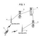
- FIG. 1illustrates a general architecture of a well-known wireless communication network.
- an access terminal (AT) 10communicates with a base station (BTS) 12 over an air interface.
- BTSbase station
- Examples of an ATinclude a mobile station, a mobile unit, a wireless phone, wireless equipped PDA or computer, etc.
- Multiple base stations 12communicate with a radio network controller (RNC) 14 , which provides signaling and traffic processing for each wireless data session.
- RNCradio network controller
- FIG. 1shows the AT 10 , BTS 12 , RNC 14 and the interfaces between these components form what is known as a radio access network (RAN).
- the RANcommunicates with a core network to access, for example, the internet.
- the core networkincludes one or more packet data service nodes (PDSNs) 16 connected between the RNCs 14 and, for example, the internet (not shown).
- PDSNspacket data service nodes
- header compressionmay occur between the AT 10 and the PDSN 16 , between the AT 10 and the RNC 14 , etc.
- the AT 10establishes a connection with the network, for example, a VoIP call
- the application layer packetwill be carried over the RTP/UDP/IP protocol stacks.
- the RTP/UDP/IP headerswill be compressed by a compressor at the AT 10 using, for example, the RoHC algorithm mentioned above.
- the compressed packetwill be sent uplink from the BTS 12 to the RNC 14 and from the RNC 14 to the PDSN 16 .
- the decompressor at the RNC 14 or the PDSN 16decompresses the RoHC header to re-establish the RTP/UDP/IP header.
- the PDSN 16 and RNC 14receive packets and the compressor at the PDSN 16 or RNC 14 compresses the RTP/UDP/IP headers to generate the RoHC or compressed header.
- the packet with compressed headeris sent to the BTS 12 and on to the AT 10 .
- a decompressor at the AT 10decompresses the RoHC header to obtain the original RTP/UDP/IP header, and passes the packet onto the application layer.
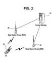
- FIG. 2illustrates another architecture of a wireless communication network—the so called flat IP network architecture.
- the AT 10communicates with a base station (BS) 20 over an air interface.
- the BS 20converges multiple mobile network elements into a single entity and combines the signaling and bearer into one IP connection.
- the BS 20contains all the radio access technology based functionalities.
- the functionalities in BTS, RNC and PDSN of FIG. 1are be converged to the BS.
- the BS 20functions like a router in the network and communicates with other BSs and network elements. Compared to FIG. 1 , there are no separate RNC and PDSN elements anymore.
- the BSmay also communicate with an access gateway 22 , which provides for external connection to other networks such as the internet.
- header compressionmay occur between the AT 10 and the BS 20 , or between the AT 10 and the access gateway 22 .
- the AT 10establishes a connection with the network, for example, a VoIP call
- the application layer packetwill be carried over the RTP/UDP/IP protocol stacks.
- the RTP/UDP/IP headerswill be compressed by a compressor at the AT 10 using, for example, the RoHC algorithm mentioned above.
- the compressed packetwill be sent uplink from the AT 10 to the BS 20 , or from the AT 10 to the BS 20 and from the BS 20 to the access gateway 22 .
- the decompressor at the BS 20 or the access gateway 22decompresses the RoHC header to re-establish the RTP/UDP/IP header.
- the access gateway 22 and BS 20receive packets, and the compressor at the access gateway 22 or the BS 22 compresses the RTP/UDP/IP headers to generate the RoHC or compressed header.
- the packet with the compressed headeris sent to the AT 10 .
- a decompressor at the AT 10decompresses the RoHC header to obtain the original RTP/UDP/IP header, and passes the packet onto the application layer.
- the robust header compression (RoHC) algorithmuses several encoding methods, including the window-based least significant bits encoding algorithm, for the compression of the dynamic fields in the protocol headers.
- the RoHC compression algorithmalso incorporates a feedback mechanism.
- the RoHC compression algorithmis very efficient on wireless links with high error rates and/or long round trip time. Because of its efficiency and robustness, the RoHC compression algorithm is suitable on wireless networks where the radio resource is costly.
- the decompressorWhen there are large consecutive packet losses in the link layer and/or a large degree of packets out of order, the decompressor is not able to decompress newly received packets. When decompression failure happens, the decompressor will loose its context.
- the context of a header compression sessionis the state of the compressor and the state of the decompressor, and these states must be synchronized for successful header reconstruction.
- the decompressorusually sends a feedback packet to the compressor instructing the compressor to resynchronize the compression status by sending the full header.
- the decompressorwill discard received packets with the compressed header, including uncorrupted packets, until the full header information is received in an uncompressed packet.
- additional packet losseswill occur, degrading the performance and quality of the call.
- the present inventionrelates to improving header compression/decompression over the radio link.
- the present inventionprovides a local repair mechanism at the decompressor that assists the decompressor in recovering from a decompression failure event (e.g., packet loss/errors or out-of-sequence receipt of packets) without having to resynchronize the compressor and decompressor.
- a decompression failure evente.g., packet loss/errors or out-of-sequence receipt of packets
- a relationshipis determined between radio link protocol (RLP) sequence numbers in received RLP packets and real-time protocol (RTP) sequence numbers in RTP packets decompressed from the received RLP packets.
- RLPradio link protocol
- RTPreal-time protocol
- a RTP sequence number associated with a compressed RTP packetis determined based on the determined relationship and at least one of the RLP sequence numbers of the received RLP packet or packets forming the compressed RTP packet.
- a relationshipis determined between protocol time stamps associated with received RLP packets and RTP time stamps in RTP packets decompressed from the received RLP packets.
- the protocol time stampis a time stamp added by a network elements interface protocol (e.g., a BTS/RNC interface protocol).
- a RTP time stamp associated with the compressed RTP packetis determined based on the determined relationship and at least one of the protocol time stamps of the received RLP packet or packets forming the compressed RTP packet.
- a RTP time stamp associated with the compressed RTP packetis determined based on at least one protocol time stamp of the received RLP packet or packets forming the compressed RTP packet, the protocol time stamp of a previously received RLP packet, and the RTP time stamp of a previously received RTP packet.
- the protocol time stampis a time stamp added by a network elements interface protocol.
- a relationshipis determined between RTP sequence numbers and associated RTP time stamps, and a RTP time stamp associated with the compressed RTP packet is determined based on the determined RTP sequence number and the determined relationship.
- the use of the protocol time stamps in the above described embodimentsmay be replaced with a time stamp derived from at least one of the transmission packet information and local timing information.
- FIG. 1illustrates a well-known wireless communication network
- FIG. 2illustrates a so called flat IP wireless communication network
- FIG. 3illustrates the architecture of a portion of a wireless communication system for reverse link communication according to an embodiment of the present invention
- FIG. 4illustrates the architecture of a portion of a wireless communication system for forward link communication according to an embodiment of the present invention.
- data packet transmissions over the link layer of the wireless networkcontain information to ensure packet delivery and processing at the RAN.
- the radio link protocol (RLP) layer at a transmitterencapsulates the RoHC packet and provides a sequence number (SN) in an RLP header for packet delivery.
- the sequence numberis incremented for each RLP packet transmission, and therefore, provides a mechanism for properly ordering packets received out-of-order at the receiver. This mechanism may also be used to recognize missing data packets.
- the interface over the backhaul between the BTS 12 and RNC 14adds another protocol (hereinafter “BTS/RNC interface protocol”) for encapsulating the RLP packets.
- BTS/RNC interface protocolmaintains timing information (e.g., a time stamp) on when RLP packets are sent between the BTS and the RNC.
- this timing informationrepresents the transmitting time the RLP packets are sent from the AT and passed by the BTS to the RNC.
- On the forward linkthere is a time stamp field in the BTS/RNC interface protocol, representing the time the RLP packet was generated at the RNC.
- the interface protocol between the functional entities BTS and RNCcan be simplified.
- the protocol time stampscan be replaced by a time stamp derived from the transmission time of the packet and the local time at the BS.
- the protocol time stampis one of the values in the interface protocol field, and the BS has the perfect knowledge of this information, since it generates the RoHC packets, and also receives the packets from the AT.
- the BSobtains the time stamp based on the time instance when a RoHC packet is generated.
- the BSreceives a packet from the AT and knows exactly when the packet is sent from the AT based on the transmission format and MAC header information.
- protocol time stampsare equally applicable to the derived time stamps in the flat IP architecture of FIG. 2 .
- each RLP packetcontains one or more RoHC packet, there is a unique mapping between the RLP SN and the compressed RTP SN in the RoHC header.
- the “first data” and “last data” field in the RLP headercan be used to reassemble a complete upper layer packet.
- the “first data” field in the RLP headeris set to 1, it means that this RLP packet contains the first portion of an upper layer packet.
- the “last data” fieldis set to 1
- both “first data” and “last data” fieldis set to 1, it means that this RLP packet contains a complete upper layer packet.
- the inventorshave recognized that the RLP SN can be used to recover the RTP SN if the RTP SN cannot be decoded successfully by the RoHC decompressor.
- the BTS/RNC interface protocol time stamprepresents the transmission timing information
- the inventorshave recognized that the BTS/RNC interface protocol time stamp has a unique relationship with the RTP time stamp. This relationship especially pertains to the reverse, or uplink, where the RTP/UDP/IP packets are generated by the application layer at the AT 10 , compressed with the RoHC, and sent out sequentially. In the architecture of FIG. 2 , it is the derived time stamp that has the unique relationship with the RTP time stamp.
- the time stamp in the BTS/RNC interface protocol headercorrelates to the RTP time stamp. For example, a VoIP packet's RTP time stamp is incremented by a fixed interval (usually 20 ms or 160 samples). The time stamp in the BTS/RNC interface protocol is also incremented by approximately the same interval if the arrival time of each VoIP packet does not vary too much. In general, the VoIP packets arriving at the RNC have been passed through the networks. Each packet will experience delay and delay jitter when it arrives at the RNC. On the other hand, the RTP time stamp in each VoIP packet represents the sampling time generated at the originating source (i.e., voice codec).
- an estimation methodmay be used to find the mapping between the RTP time stamps and the time stamps in the BTS/RNC interface protocol.
- TS RTP1(converted to ms from number of samples) be the time stamp of an RTP packet
- TS Interface1(in ms) be the time stamp of the corresponding RLP packet in the BTS/RNC interface protocol
- TS RTP2(converted to ms from number of samples) be the time stamp of the next consecutive RTP packet
- TS Interface2(in ms) be the time stamp of the corresponding RLP packet in the BTS/RNC interface protocol.
- TS RTP — intervalbe the time stamp interval between the RTP packets (i.e., 20 ms).
- the mapping between the time stamps in the interface protocol and the RTP time stampsmay be determined as follows:
- the int( )is integer operation in units of 1. Therefore, if TS RTP2 cannot be decoded correctly, the time stamps in the interface protocol may be used to estimate TS RTP2 — estimated as follows:
- the same methodmay be applied by using the derived time stamps in place of the protocol time stamps.
- the RoHC compressorWhen the received RTP/UDP/IP packets are out of order, if the RoHC compressor resides in the RNC, the RoHC compressor can inform the RLP layer about the reordering situation and the time stamps in the interface protocol can be set promptly. If the ROHC compressor resides in PDSN, the PDSN passes the reordering situation to the RNC so that the RNC can use it promptly. Therefore the same estimation method may be used to estimate the RTP time stamp if the ROHC decompressor cannot decode the time stamps correctly.
- FIG. 3illustrates a functional block diagram of the AT 10 , BTS 12 and the RNC 14 operating on a reverse link, or uplink, according to an embodiment of the present invention. It will be understood that specific details of the AT 10 , BTS 12 and RNC 14 well-known in the art have not been shown for the sake of clarity.
- Robust Header Compression (RoHC) channelsmay be established between the AT 10 and the BTS 12 , the AT 10 and RNC 14 or the AT 10 and the PDSN 16 .
- a compressor 104 and decompressor 144may reside at the AT 10 and RNC 14 (as shown in FIG. 3 ), respectively. This embodiment will be described using this implementation. However, the description is equally applicable to the decompressor residing at the BTS 12 (albeit, the BTS 12 extracts or generates the link layer information) or the PDSN 16 (albeit, the RNC 14 passes the link layer information to the PDSN 16 ).
- the AT 10includes an application layer IP generator 102 that generates IP packets for a particular application.
- a VoIP callconsists of voice frame(s) encapsulated into a RTP/UDP/IP packet.
- the application layer generator 102With the establishment of a connection, the application layer generator 102 generates an application layer packet, which via the protocol stack becomes an RTP/UDP/IP packet.
- a header compressor 104compresses the RTP/UDP/IP packets into RoHC packets, for example, using the RoHC algorithm.
- a link layer packet generator 106generates a link layer packet by placing RoHC packets into a RLP packet.
- the link layer generator 106may perform concatenation or fragmentation on the upper layer packets.
- a RLP packetcan consist of one or multiple RoHC packets. It can also contain only a portion of a RoHC packet.
- the size of the RLP packetis determined based on the available transmission rate the AT can use at the time.
- the RLP layerprovides its own SN in the RLP header for packet delivery to provide a mechanism for recognizing missing data packets.
- the BTS 12receives the RLP packet, and an interface protocol 108 adds a header to the RLP packet. More specifically, the BTS/RNC interface protocol 108 encapsulates the RLP packets, and the header of the interface protocol packet includes a packet ID (or a time stamp) representing the transmission timing information of the RLP packet at the AT 10 .
- the BTS 12passes the RLP packet to the RNC 14 or PDSN 16 (not shown) for decompression.
- Other protocols in addition to the RLP and interface protocolmay be added depending on the system design.
- the RNC 14includes a RLP processing module 142 and a decompressor 144 .
- the RLP processing module 142receives the RLP packet, obtains the RTP/UDP/IP packet there from, and passes the RLP SN and transmission timing information (hereinafter interchangeably referred to as “link layer information”) to the decompressor 144 along with the RTP/UDP/IP packet.
- link layer informationtransmission timing information
- the decompressor 144decompresses the RTP/UDP/IP packets in the well-known manner according to, for example, the RoHC algorithm. As a result of the decompression, the decompressor 144 obtains, among other things, the RTP sequence number and the RTP time stamp.
- the decompressor 144maps the RLP sequence number to the RTP sequence number, and maps the BTS/RNC interface protocol timing information to the RTP time stamp. For example, for three consecutive packets, the RLP sequence numbers may be 20, 21 and 22, and the associated three RTP sequence numbers may be 8, 9 and 10. Accordingly, RLP sequence number 20 is mapped (e.g., stored in association with) to RTP sequence number 8, RLP sequence number 21 is mapped to RTP sequence number 9, etc. as shown in Table 1 below.
- the decompressor 144may instead, or in addition, store the offset amount.
- the “first data” and “last data” field in the RLP headercan be used to determine the frame boundary (the first portion and the last portion) of the ROHC packet.
- the RLP sequence numbersmay be 20, 21, 22, 23, 24, and 25.
- the “first data” field in RLP packet 20is 1, but the “last data” field is 0. This indicates that RLP packet 20 is the first portion of a ROHC packet.
- the “first data” and “last data” in RLP packet 21are both zero.
- the “first data” in RLP packet 22is zero, and the “last data” in RLP packet 22 is 1.
- RLP packets 20 , 21 , and 22form a complete ROHC packet, with a corresponding RTP SN of 8.
- the “first data” field in RLP packet 23is 1 again, indicating the start of another upper layer packet. Accordingly, RLP sequence number 20 is mapped (e.g., stored in association with) to RTP sequence number 8, RLP sequence number 23 is mapped to RTP sequence number 9, etc. as shown in Table 2 below.
- the RLP SN to RTP SN mappingis unique but is 3 to 1 mapping.
- the interface protocol timing information and the RTP time stampare mapped in the same manner as the RLP to RTP sequence number mapping.
- the RLP processing module 142When there are many packets with errors and/or loss of packets over the wireless link, the RLP processing module 142 will discard the corrupted packets without passing them to the decompressor 144 . Packets are also received out-of-order over the wireless link.
- packetsmay again be successfully received.
- the successfully received packetswill be passed by the RLP processing module 142 to the decompressor 144 .
- the decompressor 144may not be able to decompress the received packet. This results in decompression failure.
- the decompressor 144invokes a local repair mechanism using the link layer information and attempts to decompress the received packets for which decompression failure occurred.
- the repair mechanisminvolves determining a RTP sequence number and RTP time stamp for the packet causing decompression failure.
- the decompressor 144uses the RLP sequence number for the packet, and the RLP-to-RTP sequence number map. Using the RLP-to-RTP sequence number map of Table 1 given above, an example of a RTP sequence number repair operation will be described. If the RLP sequence number of the received packet is 25, then the decompressor 144 recognizes that the RLP packets with sequence numbers 23 and 24 were missed. The decompressor 144 also determines that the RTP sequence numbers for those missing packets would have been 11 and 12—this follows the sequence set forth in Table 1. Accordingly, the decompressor 144 determines 13 as the RTP sequence number for the received packet having 25 as the RLP sequence number.
- the decompressor 144may also determine the RTP time stamp from the BTS/RNC timing information.
- Table 3shows the value of packet ID (or time stamps) in the interface protocol (in unit of 4 slots, or 6.67 ms), the corresponding transmission time (in ms), the RTP time stamp value (in unit of samples), and the corresponding sampling time.
- the estimation method of equation (2)may be used to determine a RTP time stamp from the BTS/RNC interface protocol time stamp.
- Table 4shows the same RTP time stamp and corresponding sampling time as those in Table 3.
- the packet ID for the next RTP packetis 10, corresponds to transmission time of 66.7 ms.
- packet ID 12corresponds to transmission time of 80 ms.
- the transmission time interval between consecutive packetsis not exactly 20 ms as represented by the RTP TS. However, the transmission time can still be correlated with the RTP time stamp using the estimation method of equation (2).
- the decompressor 144uses the determined RTP sequence number and RTP time stamp as the RTP sequence number and time stamp of the received packet after decompression. Then the decompressor 144 uses the CRC (cyclic redundancy check) in the ROHC header to perform error detection. If successful, the decompressor 144 will continue to decompress subsequent packets, and will have avoided decompression failure. As a result, the decompressor 144 will not need to send a feedback packet to the compressor 104 instructing the compressor 104 to resynchronize the compression status by sending the full header. The decompressor 144 will also avoid having to discard received packets with a compressed header, including uncorrupted packets, until the full header information is received in an uncompressed packet.
- CRCcyclic redundancy check
- FIG. 4illustrates a functional block diagram of the AT 10 , BTS 12 and the RNC 14 operating over the forward link, or downlink, according to an embodiment of the present invention. It will be understood that specific details of the AT 10 , BTS 12 and RNC 14 well-known in the art (e.g., the RTP/UDP/IP protocol stacks, etc.) have not been shown for the sake of clarity.
- Robust Header Compression (ROHC) channelsmay be established between the AT 10 and the BTS 12 , the AT 10 and RNC 14 or the AT 10 and the PDSN 16 .
- a compressor 204 and decompressor 244may reside at the RNC 14 and AT 10 (as shown in FIG. 4 ), respectively. This embodiment will be described using this implementation. However, the description is equally applicable to the compressor residing at the BTS 12 or the PDSN 16 .
- the RNC 14includes an application layer IP generator 202 that generates IP packets for a particular application.
- a VoIP callconsists of voice frame(s) encapsulated into a RTP/UDP/IP packet.
- the application layer generator 202With the establishment of a connection, the application layer generator 202 generates an application layer packet, which via the protocol stack becomes an RTP/UDP/IP packet.
- a header compressor 204compresses the RTP/UDP/IP packets into ROHC packets, for example, using the ROHC algorithm.
- a link layer packet generator 206generates a link layer packet by placing each ROHC packet into a RLP packet.
- the RLP layerprovides its own SN in the RLP header for packet delivery to provide a mechanism for recognizing missing data packets.
- the ROHC packetmay be fragmented into more than one RLP packet.
- a BTS/RNC interface protocol 208 at the RNCadds an interface protocol header to the RLP packet before sending the RLP packet to the BTS. More specifically, the BTS/RNC interface protocol encapsulates the RLP packets, and the header of the interface protocol packet includes a sequence number representing the transmission timing information of the RLP packet. The BTS 12 removes the BTS/RNC interface protocol header and passes the RLP packet to the AT 10 for decompression. Other protocols in addition to the RLP and interface protocol may be added depending on the system design.
- the AT 10includes a RLP processing module 242 and a decompressor 244 .
- the RLP processing module 242receives the RLP packet, obtains the RTP/UDP/IP packet there from, and passes the RLP SN and transmission timing information (hereinafter interchangeably referred to as “link layer information”) to the decompressor 244 along with the RTP/UDP/IP packet.
- link layer informationtransmission timing information
- the decompressor 244decompresses the RTP/UDP/IP packets in the well-known manner according to, for example, the ROHC algorithm. As a result of the decompression, the decompressor 244 obtains, among other things, the RTP sequence number and the RTP time stamp. The decompressor 244 maps the RLP sequence number to the RTP sequence number, and maps the BTS/RNC interface protocol timing information to the RTP time stamp in the same manner described above in detail with respect to the reverse link.
- the decompressor 244performs a local repair mechanism in the same manner as described above with respect to the reverse link, except for the determination of the RTP time stamp.
- the BTS/RNC interface protocol headeris not sent with the RLP packets from the BTS to the AT. Accordingly, the BTS/RNC interface protocol timing information is not available to the AT for use in the local repair mechanism.
- this timing informationmay be sent to the AT, albeit not in the BTS/RNC interface protocol header.
- this timing informationmay be sent by BTS to AT via additional signaling, either with an added field in the RLP header or with an added message sent separately to the AT.
- the RTP time stampis inferred using the repaired RTP sequence number (SN).
- the RTP time stampis defined to identify the number of samples used to generate the RTP packet payload.
- RTP packetscarry payloads corresponding to a fixed sampling interval, and the sample rate is fixed, there is a unique mapping between the TS and SN. For example, for conversational speech, a fixed sampling rate of 8 kHz is often used. The speech payload is generated every 20 ms. This is equivalent to an increment of 160 in the RTP TS domain for consecutive packets.
- the RTP SN numberis incremented by 1, while the TS is incremented by 160 during a talk spurt (where no silence suppression is applied.)
- the TSmay be recovered indirectly.
- the local repair mechanismin accordance with the system and methods provided may reduce the decompression failure and/or the resynchronization between the compressor and the decompressor.
Landscapes
- Engineering & Computer Science (AREA)
- Computer Networks & Wireless Communication (AREA)
- Signal Processing (AREA)
- Computer Security & Cryptography (AREA)
- Mobile Radio Communication Systems (AREA)
- Time-Division Multiplex Systems (AREA)
- Data Exchanges In Wide-Area Networks (AREA)
- Detection And Prevention Of Errors In Transmission (AREA)
- Reduction Or Emphasis Of Bandwidth Of Signals (AREA)
Abstract
Description
where the int( ) is integer operation in units of 1. Therefore, if TSRTP2cannot be decoded correctly, the time stamps in the interface protocol may be used to estimate TSRTP2
When there is a jump in the RTP time stamp during the silence compression, the above method may still be used to estimate the RTP time stamp.
| TABLE 1 | |||
| RLP Sequence Number | |||
| 20 | 8 | ||
| 21 | 9 | ||
| 22 | 10 | ||
| TABLE 2 | |||
| RLP Sequence Number | |||
| 20 | 8 | ||
| 21 | (8) | ||
| 22 | (8) | ||
| 23 | 9 | ||
| 24 | (9) | ||
| 25 | (9) | ||
| 26 | 10 | ||
In this example, the RLP SN to RTP SN mapping is unique but is 3 to 1 mapping.
| TABLE 3 | |||||
| Corresponding | Corresponding | ||||
| transmission | RTP Time | sampling time | |||
| Packet ID | time (ms) | Stamp | (ms) | ||
| 6 | 40 | 160 | 20 | ||
| 9 | 60 | 320 | 40 | ||
| 12 | 80 | 480 | 60 | ||
The transmission time can be correlated with the RTP time stamp. In this example, the transmission time is mapped to the RTP packet sampling time by an offset of 20 ms, i.e., 40 ms is mapped to 20 ms. If there are missing packets, the
| TABLE 4 | |||||
| Corresponding | Corresponding | ||||
| transmission | RTP Time | sampling time | |||
| Packet ID | time (ms) | Stamp | (ms) | ||
| 6 | 40 | 160 | 20 | ||
| 10 | 66.7 | 320 | 40 | ||
| 12 | 80 | 480 | 60 | ||
In this example, if there are missing packets, the
Claims (24)
Priority Applications (6)
| Application Number | Priority Date | Filing Date | Title |
|---|---|---|---|
| US11/644,879US8027328B2 (en) | 2006-12-26 | 2006-12-26 | Header compression in a wireless communication network |
| AT07863016TATE488973T1 (en) | 2006-12-26 | 2007-12-17 | IMPROVED HEADER COMPRESSION IN A WIRELESS COMMUNICATIONS NETWORK |
| EP07863016AEP2098035B1 (en) | 2006-12-26 | 2007-12-17 | Improved header compression in a wireless communication network |
| JP2009542844AJP5084842B2 (en) | 2006-12-26 | 2007-12-17 | Improved header compression in wireless communication networks |
| DE602007010662TDE602007010662D1 (en) | 2006-12-26 | 2007-12-17 | IMPROVED HEADER COMPRESSION IN A WIRELESS COMMUNICATION NETWORK |
| PCT/US2007/025776WO2008085336A2 (en) | 2006-12-26 | 2007-12-17 | Improved header compression in a wireless communication network |
Applications Claiming Priority (1)
| Application Number | Priority Date | Filing Date | Title |
|---|---|---|---|
| US11/644,879US8027328B2 (en) | 2006-12-26 | 2006-12-26 | Header compression in a wireless communication network |
Publications (2)
| Publication Number | Publication Date |
|---|---|
| US20080151901A1 US20080151901A1 (en) | 2008-06-26 |
| US8027328B2true US8027328B2 (en) | 2011-09-27 |
Family
ID=39300138
Family Applications (1)
| Application Number | Title | Priority Date | Filing Date |
|---|---|---|---|
| US11/644,879Expired - Fee RelatedUS8027328B2 (en) | 2006-12-26 | 2006-12-26 | Header compression in a wireless communication network |
Country Status (6)
| Country | Link |
|---|---|
| US (1) | US8027328B2 (en) |
| EP (1) | EP2098035B1 (en) |
| JP (1) | JP5084842B2 (en) |
| AT (1) | ATE488973T1 (en) |
| DE (1) | DE602007010662D1 (en) |
| WO (1) | WO2008085336A2 (en) |
Cited By (32)
| Publication number | Priority date | Publication date | Assignee | Title |
|---|---|---|---|---|
| US20070204196A1 (en)* | 2006-02-13 | 2007-08-30 | Digital Fountain, Inc. | Streaming and buffering using variable fec overhead and protection periods |
| US20090307565A1 (en)* | 2004-08-11 | 2009-12-10 | Digital Fountain, Inc. | Method and apparatus for fast encoding of data symbols according to half-weight codes |
| US20100318670A1 (en)* | 2009-06-16 | 2010-12-16 | Futurewei Technologies, Inc. | System and Method for Adapting an Application Source Rate to a Load Condition |
| US20120207068A1 (en)* | 2011-02-11 | 2012-08-16 | Qualcomm Incorporated | Framing for an improved radio link protocol including fec |
| US8806050B2 (en) | 2010-08-10 | 2014-08-12 | Qualcomm Incorporated | Manifest file updates for network streaming of coded multimedia data |
| US8887020B2 (en) | 2003-10-06 | 2014-11-11 | Digital Fountain, Inc. | Error-correcting multi-stage code generator and decoder for communication systems having single transmitters or multiple transmitters |
| US8918533B2 (en) | 2010-07-13 | 2014-12-23 | Qualcomm Incorporated | Video switching for streaming video data |
| US9136878B2 (en) | 2004-05-07 | 2015-09-15 | Digital Fountain, Inc. | File download and streaming system |
| US9178535B2 (en) | 2006-06-09 | 2015-11-03 | Digital Fountain, Inc. | Dynamic stream interleaving and sub-stream based delivery |
| US9185439B2 (en) | 2010-07-15 | 2015-11-10 | Qualcomm Incorporated | Signaling data for multiplexing video components |
| US9191151B2 (en) | 2006-06-09 | 2015-11-17 | Qualcomm Incorporated | Enhanced block-request streaming using cooperative parallel HTTP and forward error correction |
| US9236976B2 (en) | 2001-12-21 | 2016-01-12 | Digital Fountain, Inc. | Multi stage code generator and decoder for communication systems |
| US9236885B2 (en) | 2002-10-05 | 2016-01-12 | Digital Fountain, Inc. | Systematic encoding and decoding of chain reaction codes |
| US9237101B2 (en) | 2007-09-12 | 2016-01-12 | Digital Fountain, Inc. | Generating and communicating source identification information to enable reliable communications |
| US9240810B2 (en) | 2002-06-11 | 2016-01-19 | Digital Fountain, Inc. | Systems and processes for decoding chain reaction codes through inactivation |
| US9246633B2 (en) | 1998-09-23 | 2016-01-26 | Digital Fountain, Inc. | Information additive code generator and decoder for communication systems |
| US9253233B2 (en) | 2011-08-31 | 2016-02-02 | Qualcomm Incorporated | Switch signaling methods providing improved switching between representations for adaptive HTTP streaming |
| US9264069B2 (en) | 2006-05-10 | 2016-02-16 | Digital Fountain, Inc. | Code generator and decoder for communications systems operating using hybrid codes to allow for multiple efficient uses of the communications systems |
| US9270299B2 (en) | 2011-02-11 | 2016-02-23 | Qualcomm Incorporated | Encoding and decoding using elastic codes with flexible source block mapping |
| US9270414B2 (en) | 2006-02-21 | 2016-02-23 | Digital Fountain, Inc. | Multiple-field based code generator and decoder for communications systems |
| US9281847B2 (en) | 2009-02-27 | 2016-03-08 | Qualcomm Incorporated | Mobile reception of digital video broadcasting—terrestrial services |
| US9288010B2 (en) | 2009-08-19 | 2016-03-15 | Qualcomm Incorporated | Universal file delivery methods for providing unequal error protection and bundled file delivery services |
| US9294226B2 (en) | 2012-03-26 | 2016-03-22 | Qualcomm Incorporated | Universal object delivery and template-based file delivery |
| US9380096B2 (en) | 2006-06-09 | 2016-06-28 | Qualcomm Incorporated | Enhanced block-request streaming system for handling low-latency streaming |
| US9386064B2 (en) | 2006-06-09 | 2016-07-05 | Qualcomm Incorporated | Enhanced block-request streaming using URL templates and construction rules |
| US9419749B2 (en) | 2009-08-19 | 2016-08-16 | Qualcomm Incorporated | Methods and apparatus employing FEC codes with permanent inactivation of symbols for encoding and decoding processes |
| US9432433B2 (en) | 2006-06-09 | 2016-08-30 | Qualcomm Incorporated | Enhanced block-request streaming system using signaling or block creation |
| US9485546B2 (en) | 2010-06-29 | 2016-11-01 | Qualcomm Incorporated | Signaling video samples for trick mode video representations |
| US9596447B2 (en) | 2010-07-21 | 2017-03-14 | Qualcomm Incorporated | Providing frame packing type information for video coding |
| US9843844B2 (en) | 2011-10-05 | 2017-12-12 | Qualcomm Incorporated | Network streaming of media data |
| US9917874B2 (en) | 2009-09-22 | 2018-03-13 | Qualcomm Incorporated | Enhanced block-request streaming using block partitioning or request controls for improved client-side handling |
| US10009401B2 (en) | 2015-09-23 | 2018-06-26 | Qualcomm Incorporated | Call continuity in high uplink interference state |
Families Citing this family (12)
| Publication number | Priority date | Publication date | Assignee | Title |
|---|---|---|---|---|
| GB0700750D0 (en)* | 2007-01-15 | 2007-02-21 | Samsung Electronics Co Ltd | Mobile communications |
| WO2008139594A1 (en)* | 2007-05-11 | 2008-11-20 | Fujitsu Limited | Method of controlling header compression in wireless communication, and wireless station and transmitting device |
| US20090052453A1 (en)* | 2007-08-22 | 2009-02-26 | Minkyu Lee | Method and apparatus for improving the performance of voice over IP (VoIP) speech communications systems which use robust header compression (RoHC) techniques |
| CN101369880B (en)* | 2008-09-28 | 2012-09-19 | 华为技术有限公司 | A method and device for detecting and processing time label jumps |
| CN102571540B (en)* | 2010-12-20 | 2015-12-16 | 华为技术有限公司 | A method and device for decompression |
| CN103260187B (en)* | 2012-02-20 | 2016-03-02 | 华为技术有限公司 | The method of research content presynchronization, equipment and system |
| US9357435B2 (en)* | 2013-11-06 | 2016-05-31 | Samsung Electronics Co., Ltd. | Method and system for handling audio packets during a volte call |
| WO2016108610A1 (en) | 2015-01-02 | 2016-07-07 | 엘지전자 주식회사 | Broadcast signal transmission apparatus, broadcast signal receiving apparatus, broadcast signal transmission method, and broadcast signal receiving method |
| CN106464676B (en) | 2015-01-02 | 2019-12-31 | Lg 电子株式会社 | Broadcast signal transmitting apparatus, broadcast signal receiving apparatus, broadcast signal transmitting method, and broadcast signal receiving method |
| WO2016108606A1 (en) | 2015-01-02 | 2016-07-07 | 엘지전자 주식회사 | Broadcast signal transmission apparatus, broadcast signal reception apparatus, broadcast signal transmission method, and broadcast signal reception method |
| US9924000B2 (en) | 2016-03-14 | 2018-03-20 | Sprint Communications Company L.P. | Communication packet header data compression |
| CN111385263B (en)* | 2018-12-29 | 2022-05-24 | 大唐移动通信设备有限公司 | Method for maintaining data packet header compression information and communication equipment |
Citations (26)
| Publication number | Priority date | Publication date | Assignee | Title |
|---|---|---|---|---|
| EP1056259A1 (en) | 1999-05-25 | 2000-11-29 | Lucent Technologies Inc. | Method and apparatus for telecommunications using internet protocol |
| WO2000079762A1 (en) | 1999-06-18 | 2000-12-28 | Telefonaktiebolaget Lm Ericsson (Publ) | Estimation of time stamps in real-time packet communications |
| WO2001067709A2 (en) | 2000-03-09 | 2001-09-13 | Nokia Corporation | A technique for compressing a header field in a data packet |
| US20010030963A1 (en)* | 2000-03-03 | 2001-10-18 | Takeshi Yoshimura | Method and apparatus for packet transmission with header compression |
| US20010030965A1 (en) | 2000-02-14 | 2001-10-18 | Nokia Mobile Phones Ltd. | Data packet numbering in packet-switched data transmission |
| WO2002045357A2 (en) | 2000-11-30 | 2002-06-06 | Telefonaktiebolaget Lm Ericsson (Publ) | Method and system for transmission of headerless data packets over a wireless link |
| US20020089998A1 (en)* | 1999-04-01 | 2002-07-11 | Khiem Le | Apparatus and associated method for communicating multimedia information upon a communication link |
| US20020150092A1 (en) | 2001-04-17 | 2002-10-17 | Richard Bontempi | One-to-one communication |
| US20030039270A1 (en) | 2001-08-24 | 2003-02-27 | Samsung Electronics Co., Ltd. | Signaling method between MAC entities in a packet communication system |
| US20030079230A1 (en) | 2001-10-19 | 2003-04-24 | Woodward William D. | Interfacing at least one information stream with at least one modulator |
| US20040022262A1 (en) | 2002-07-31 | 2004-02-05 | Bapiraju Vinnakota | State-based jitter buffer and method of operation |
| US20040088642A1 (en) | 2001-09-28 | 2004-05-06 | Koji Imura | Header compression packet reception apparatus and method |
| US20040179689A1 (en) | 2000-03-03 | 2004-09-16 | Mark Maggenti | Communication device for providing security in a group communication network |
| US20040264433A1 (en)* | 2001-11-06 | 2004-12-30 | Diego Melpignano | Wireless communication arrangements with header compression |
| US20050157696A1 (en) | 2004-01-15 | 2005-07-21 | Sony Ericsson Mobile Communications Japan, Inc. | Data transmission method and data transmission apparatus |
| US20050193309A1 (en) | 2003-08-21 | 2005-09-01 | Francesco Grilli | Methods for forward error correction coding above a radio link control layer and related apparatus |
| US20060002416A1 (en) | 2004-07-01 | 2006-01-05 | Nec Corporation | Mobile radio communication terminal device capable of realizing a MAC-HS buffer and RLC buffer in one physical memory and suppressing memory capacity |
| US20060120352A1 (en)* | 2004-12-08 | 2006-06-08 | Agashe Parag A | Methods and systems for enhancing local repair in robust header compression |
| US7124349B2 (en) | 2002-04-30 | 2006-10-17 | Psytechnics Limited | Method and apparatus for transmission error characterization |
| US7133943B2 (en) | 2003-02-26 | 2006-11-07 | International Business Machines Corporation | Method and apparatus for implementing receive queue for packet-based communications |
| US20070047547A1 (en)* | 2005-08-26 | 2007-03-01 | Conner Keith F | Header elimination for real time internet applications |
| US20070047551A1 (en)* | 2005-08-26 | 2007-03-01 | Conner Keith F | Header compression for real time internet applications |
| US7298717B2 (en) | 2002-02-15 | 2007-11-20 | Texas Instruments Incorporated | Method and apparatus for providing transmit diversity with adaptive basis |
| US20080025312A1 (en)* | 2006-07-28 | 2008-01-31 | Qualcomm Incorporated | Zero-header compression for improved communications |
| US7359372B2 (en) | 2002-06-12 | 2008-04-15 | Telefonaktibolaget Lm Ericsson (Publ) | Method and apparatus for fast change of internet protocol headers compression mechanism |
| US7697447B2 (en) | 2001-08-10 | 2010-04-13 | Motorola Inc. | Control of jitter buffer size and depth |
- 2006
- 2006-12-26USUS11/644,879patent/US8027328B2/ennot_activeExpired - Fee Related
- 2007
- 2007-12-17JPJP2009542844Apatent/JP5084842B2/ennot_activeExpired - Fee Related
- 2007-12-17DEDE602007010662Tpatent/DE602007010662D1/enactiveActive
- 2007-12-17ATAT07863016Tpatent/ATE488973T1/ennot_activeIP Right Cessation
- 2007-12-17WOPCT/US2007/025776patent/WO2008085336A2/enactiveApplication Filing
- 2007-12-17EPEP07863016Apatent/EP2098035B1/ennot_activeCeased
Patent Citations (29)
| Publication number | Priority date | Publication date | Assignee | Title |
|---|---|---|---|---|
| US20020089998A1 (en)* | 1999-04-01 | 2002-07-11 | Khiem Le | Apparatus and associated method for communicating multimedia information upon a communication link |
| US20040095939A1 (en) | 1999-05-25 | 2004-05-20 | Jin Yang | Method and apparatus for telecommunications using internet protocol |
| EP1056259A1 (en) | 1999-05-25 | 2000-11-29 | Lucent Technologies Inc. | Method and apparatus for telecommunications using internet protocol |
| US6788675B1 (en)* | 1999-05-25 | 2004-09-07 | Lucent Technologies Inc. | Method and apparatus for telecommunications using internet protocol |
| WO2000079762A1 (en) | 1999-06-18 | 2000-12-28 | Telefonaktiebolaget Lm Ericsson (Publ) | Estimation of time stamps in real-time packet communications |
| US6680955B1 (en) | 1999-08-20 | 2004-01-20 | Nokia Networks Oy | Technique for compressing a header field in a data packet |
| US20010030965A1 (en) | 2000-02-14 | 2001-10-18 | Nokia Mobile Phones Ltd. | Data packet numbering in packet-switched data transmission |
| US20010030963A1 (en)* | 2000-03-03 | 2001-10-18 | Takeshi Yoshimura | Method and apparatus for packet transmission with header compression |
| US20040179689A1 (en) | 2000-03-03 | 2004-09-16 | Mark Maggenti | Communication device for providing security in a group communication network |
| WO2001067709A2 (en) | 2000-03-09 | 2001-09-13 | Nokia Corporation | A technique for compressing a header field in a data packet |
| WO2002045357A2 (en) | 2000-11-30 | 2002-06-06 | Telefonaktiebolaget Lm Ericsson (Publ) | Method and system for transmission of headerless data packets over a wireless link |
| US20020150092A1 (en) | 2001-04-17 | 2002-10-17 | Richard Bontempi | One-to-one communication |
| US7697447B2 (en) | 2001-08-10 | 2010-04-13 | Motorola Inc. | Control of jitter buffer size and depth |
| US20030039270A1 (en) | 2001-08-24 | 2003-02-27 | Samsung Electronics Co., Ltd. | Signaling method between MAC entities in a packet communication system |
| US20040088642A1 (en) | 2001-09-28 | 2004-05-06 | Koji Imura | Header compression packet reception apparatus and method |
| US20030079230A1 (en) | 2001-10-19 | 2003-04-24 | Woodward William D. | Interfacing at least one information stream with at least one modulator |
| US20040264433A1 (en)* | 2001-11-06 | 2004-12-30 | Diego Melpignano | Wireless communication arrangements with header compression |
| US7298717B2 (en) | 2002-02-15 | 2007-11-20 | Texas Instruments Incorporated | Method and apparatus for providing transmit diversity with adaptive basis |
| US7124349B2 (en) | 2002-04-30 | 2006-10-17 | Psytechnics Limited | Method and apparatus for transmission error characterization |
| US7359372B2 (en) | 2002-06-12 | 2008-04-15 | Telefonaktibolaget Lm Ericsson (Publ) | Method and apparatus for fast change of internet protocol headers compression mechanism |
| US20040022262A1 (en) | 2002-07-31 | 2004-02-05 | Bapiraju Vinnakota | State-based jitter buffer and method of operation |
| US7133943B2 (en) | 2003-02-26 | 2006-11-07 | International Business Machines Corporation | Method and apparatus for implementing receive queue for packet-based communications |
| US20050193309A1 (en) | 2003-08-21 | 2005-09-01 | Francesco Grilli | Methods for forward error correction coding above a radio link control layer and related apparatus |
| US20050157696A1 (en) | 2004-01-15 | 2005-07-21 | Sony Ericsson Mobile Communications Japan, Inc. | Data transmission method and data transmission apparatus |
| US20060002416A1 (en) | 2004-07-01 | 2006-01-05 | Nec Corporation | Mobile radio communication terminal device capable of realizing a MAC-HS buffer and RLC buffer in one physical memory and suppressing memory capacity |
| US20060120352A1 (en)* | 2004-12-08 | 2006-06-08 | Agashe Parag A | Methods and systems for enhancing local repair in robust header compression |
| US20070047551A1 (en)* | 2005-08-26 | 2007-03-01 | Conner Keith F | Header compression for real time internet applications |
| US20070047547A1 (en)* | 2005-08-26 | 2007-03-01 | Conner Keith F | Header elimination for real time internet applications |
| US20080025312A1 (en)* | 2006-07-28 | 2008-01-31 | Qualcomm Incorporated | Zero-header compression for improved communications |
Non-Patent Citations (10)
| Title |
|---|
| Bormann et al., "Robust Header Compression (ROHC): Framework and Four Profiles: RTP, UDP, ESP and Uncompressed, RFC 3095", Internet Engineering Task Force (IETF), Jul. 2001, XP015008878 Section 4.5.4. |
| Bormann et al., RFC 3095-RObust Header Compression (ROHC): Framework and four profiles: RTP, UDP, ESP and uncompressed, Jul. 2001.* |
| G. Pelletier, "Robust Header Compression (ROHC): Profiles for User Datagram Protocol (UDP) Lite", RFC 4019 (rfc4019), Network Working Group, Request for Comments: 4019, Category: Standards Track, Apr. 2005, pp. 1-16. |
| International Search Report and Written Opinion dated Jul. 8, 2008. |
| International Search Report and Written Opinion of the International Authority dated Apr. 3, 2008, for counterpart International Application No. PCT/US2007/025552. |
| J. Postel, RF 768 (rfc768)-User Datagram Protocol, Aug. 28, 1980, pp. 1-3. |
| J. Sjoberg et al., "Real-Time Transport Protocol (RTP) Payload Format and File Storage Format for the Adaptive Multi-Rate (AMR) and Adaptive Multi-rate Wideband (AMR-WB) Audio Codecs", Network Working Group, Request for Comments: 3267, Category: Standards Track, Jun. 2002, pp. 1-35. |
| Jonsson et al., RObust Header Compression (ROHC): A Link-Layer Assisted Profile for IP/UDP/RTP, Apr. 2002.* |
| L-A. Larzon et al., "The Lightweight User Datagram Protocol (UDP-Lite), RFC 3828 (rfc3828)", Network Working Group, Request for comments: 3828, Category: Standards Track, Jul. 2004, pp. 1-9. |
| Svanbro, "Lower Layer Guidelines for Robust RTP/UDP/IP Header Compression, RFC 3409", Internet Engineering Task Force (IETF), Dec. 2002, XP015009203 Section 2.2. |
Cited By (50)
| Publication number | Priority date | Publication date | Assignee | Title |
|---|---|---|---|---|
| US9246633B2 (en) | 1998-09-23 | 2016-01-26 | Digital Fountain, Inc. | Information additive code generator and decoder for communication systems |
| US9236976B2 (en) | 2001-12-21 | 2016-01-12 | Digital Fountain, Inc. | Multi stage code generator and decoder for communication systems |
| US9240810B2 (en) | 2002-06-11 | 2016-01-19 | Digital Fountain, Inc. | Systems and processes for decoding chain reaction codes through inactivation |
| US9236885B2 (en) | 2002-10-05 | 2016-01-12 | Digital Fountain, Inc. | Systematic encoding and decoding of chain reaction codes |
| US8887020B2 (en) | 2003-10-06 | 2014-11-11 | Digital Fountain, Inc. | Error-correcting multi-stage code generator and decoder for communication systems having single transmitters or multiple transmitters |
| US9236887B2 (en) | 2004-05-07 | 2016-01-12 | Digital Fountain, Inc. | File download and streaming system |
| US9136878B2 (en) | 2004-05-07 | 2015-09-15 | Digital Fountain, Inc. | File download and streaming system |
| US20090307565A1 (en)* | 2004-08-11 | 2009-12-10 | Digital Fountain, Inc. | Method and apparatus for fast encoding of data symbols according to half-weight codes |
| US20070204196A1 (en)* | 2006-02-13 | 2007-08-30 | Digital Fountain, Inc. | Streaming and buffering using variable fec overhead and protection periods |
| US9136983B2 (en) | 2006-02-13 | 2015-09-15 | Digital Fountain, Inc. | Streaming and buffering using variable FEC overhead and protection periods |
| US9270414B2 (en) | 2006-02-21 | 2016-02-23 | Digital Fountain, Inc. | Multiple-field based code generator and decoder for communications systems |
| US9264069B2 (en) | 2006-05-10 | 2016-02-16 | Digital Fountain, Inc. | Code generator and decoder for communications systems operating using hybrid codes to allow for multiple efficient uses of the communications systems |
| US9191151B2 (en) | 2006-06-09 | 2015-11-17 | Qualcomm Incorporated | Enhanced block-request streaming using cooperative parallel HTTP and forward error correction |
| US9209934B2 (en) | 2006-06-09 | 2015-12-08 | Qualcomm Incorporated | Enhanced block-request streaming using cooperative parallel HTTP and forward error correction |
| US9432433B2 (en) | 2006-06-09 | 2016-08-30 | Qualcomm Incorporated | Enhanced block-request streaming system using signaling or block creation |
| US9386064B2 (en) | 2006-06-09 | 2016-07-05 | Qualcomm Incorporated | Enhanced block-request streaming using URL templates and construction rules |
| US9628536B2 (en) | 2006-06-09 | 2017-04-18 | Qualcomm Incorporated | Enhanced block-request streaming using cooperative parallel HTTP and forward error correction |
| US11477253B2 (en) | 2006-06-09 | 2022-10-18 | Qualcomm Incorporated | Enhanced block-request streaming system using signaling or block creation |
| US9178535B2 (en) | 2006-06-09 | 2015-11-03 | Digital Fountain, Inc. | Dynamic stream interleaving and sub-stream based delivery |
| US9380096B2 (en) | 2006-06-09 | 2016-06-28 | Qualcomm Incorporated | Enhanced block-request streaming system for handling low-latency streaming |
| US9237101B2 (en) | 2007-09-12 | 2016-01-12 | Digital Fountain, Inc. | Generating and communicating source identification information to enable reliable communications |
| US9281847B2 (en) | 2009-02-27 | 2016-03-08 | Qualcomm Incorporated | Mobile reception of digital video broadcasting—terrestrial services |
| US10880221B2 (en) | 2009-06-16 | 2020-12-29 | Futurewei Technologies, Inc. | System and method for adapting an application source rate to a load condition |
| US9357568B2 (en)* | 2009-06-16 | 2016-05-31 | Futurewei Technologies, Inc. | System and method for adapting an application source rate to a load condition |
| US20100318670A1 (en)* | 2009-06-16 | 2010-12-16 | Futurewei Technologies, Inc. | System and Method for Adapting an Application Source Rate to a Load Condition |
| US9876607B2 (en) | 2009-08-19 | 2018-01-23 | Qualcomm Incorporated | Methods and apparatus employing FEC codes with permanent inactivation of symbols for encoding and decoding processes |
| US9288010B2 (en) | 2009-08-19 | 2016-03-15 | Qualcomm Incorporated | Universal file delivery methods for providing unequal error protection and bundled file delivery services |
| US9660763B2 (en) | 2009-08-19 | 2017-05-23 | Qualcomm Incorporated | Methods and apparatus employing FEC codes with permanent inactivation of symbols for encoding and decoding processes |
| US9419749B2 (en) | 2009-08-19 | 2016-08-16 | Qualcomm Incorporated | Methods and apparatus employing FEC codes with permanent inactivation of symbols for encoding and decoding processes |
| US12155715B2 (en) | 2009-09-22 | 2024-11-26 | Qualcomm Incorporated | Enhanced block-request streaming using block partitioning or request controls for improved client-side handling |
| US11770432B2 (en) | 2009-09-22 | 2023-09-26 | Qualcomm Incorporated | Enhanced block-request streaming system for handling low-latency streaming |
| US10855736B2 (en) | 2009-09-22 | 2020-12-01 | Qualcomm Incorporated | Enhanced block-request streaming using block partitioning or request controls for improved client-side handling |
| US11743317B2 (en) | 2009-09-22 | 2023-08-29 | Qualcomm Incorporated | Enhanced block-request streaming using block partitioning or request controls for improved client-side handling |
| US9917874B2 (en) | 2009-09-22 | 2018-03-13 | Qualcomm Incorporated | Enhanced block-request streaming using block partitioning or request controls for improved client-side handling |
| US9485546B2 (en) | 2010-06-29 | 2016-11-01 | Qualcomm Incorporated | Signaling video samples for trick mode video representations |
| US9992555B2 (en) | 2010-06-29 | 2018-06-05 | Qualcomm Incorporated | Signaling random access points for streaming video data |
| US8918533B2 (en) | 2010-07-13 | 2014-12-23 | Qualcomm Incorporated | Video switching for streaming video data |
| US9185439B2 (en) | 2010-07-15 | 2015-11-10 | Qualcomm Incorporated | Signaling data for multiplexing video components |
| US9596447B2 (en) | 2010-07-21 | 2017-03-14 | Qualcomm Incorporated | Providing frame packing type information for video coding |
| US9602802B2 (en) | 2010-07-21 | 2017-03-21 | Qualcomm Incorporated | Providing frame packing type information for video coding |
| US9319448B2 (en) | 2010-08-10 | 2016-04-19 | Qualcomm Incorporated | Trick modes for network streaming of coded multimedia data |
| US9456015B2 (en) | 2010-08-10 | 2016-09-27 | Qualcomm Incorporated | Representation groups for network streaming of coded multimedia data |
| US8806050B2 (en) | 2010-08-10 | 2014-08-12 | Qualcomm Incorporated | Manifest file updates for network streaming of coded multimedia data |
| US8958375B2 (en)* | 2011-02-11 | 2015-02-17 | Qualcomm Incorporated | Framing for an improved radio link protocol including FEC |
| US20120207068A1 (en)* | 2011-02-11 | 2012-08-16 | Qualcomm Incorporated | Framing for an improved radio link protocol including fec |
| US9270299B2 (en) | 2011-02-11 | 2016-02-23 | Qualcomm Incorporated | Encoding and decoding using elastic codes with flexible source block mapping |
| US9253233B2 (en) | 2011-08-31 | 2016-02-02 | Qualcomm Incorporated | Switch signaling methods providing improved switching between representations for adaptive HTTP streaming |
| US9843844B2 (en) | 2011-10-05 | 2017-12-12 | Qualcomm Incorporated | Network streaming of media data |
| US9294226B2 (en) | 2012-03-26 | 2016-03-22 | Qualcomm Incorporated | Universal object delivery and template-based file delivery |
| US10009401B2 (en) | 2015-09-23 | 2018-06-26 | Qualcomm Incorporated | Call continuity in high uplink interference state |
Also Published As
| Publication number | Publication date |
|---|---|
| JP2010515295A (en) | 2010-05-06 |
| WO2008085336A3 (en) | 2008-09-12 |
| JP5084842B2 (en) | 2012-11-28 |
| US20080151901A1 (en) | 2008-06-26 |
| EP2098035A2 (en) | 2009-09-09 |
| ATE488973T1 (en) | 2010-12-15 |
| EP2098035B1 (en) | 2010-11-17 |
| DE602007010662D1 (en) | 2010-12-30 |
| WO2008085336A2 (en) | 2008-07-17 |
Similar Documents
| Publication | Publication Date | Title |
|---|---|---|
| US8027328B2 (en) | Header compression in a wireless communication network | |
| US9357039B2 (en) | Header elimination for real time internet applications | |
| US8175075B2 (en) | Adaptive header compression in a wireless communication network | |
| US7899025B2 (en) | Header suppression in a wireless communication network | |
| US6879581B1 (en) | Method and apparatus for providing real-time packetized voice and data services over a wireless communication network | |
| JP3694241B2 (en) | Method and apparatus for telecommunications using Internet protocols | |
| US6993021B1 (en) | Lightweight internet protocol encapsulation (LIPE) scheme for multimedia traffic transport | |
| KR100697355B1 (en) | Extended header compression | |
| EP1362446B1 (en) | Transfer of ip data in communications system, using several logical connections for compressed fields on the basis of different contexts | |
| EP1220498A2 (en) | Method and system for transmission of headerless data packets over a wireless link | |
| JP2005509381A6 (en) | Wireless communication device for header compression | |
| JP2005509381A (en) | Wireless communication device for header compression | |
| CN107566330B (en) | Apparatus adapted to maintain received data quality and method for receiving data | |
| US8537741B2 (en) | Method of header compression over channels with out-of-order delivery | |
| US9148257B2 (en) | Method and apparatus for reducing delays in a packets switched network | |
| CN108737349B (en) | Voice data packet processing method and device | |
| CN1802567B (en) | Method and system for performing compression on user datagram protocol packets | |
| Rawat et al. | Robust header compression over long delay links | |
| Zhang | WLC04-2: Performance of Robust Header Compression for VoIP in 1xEV-DO Revision A System |
Legal Events
| Date | Code | Title | Description |
|---|---|---|---|
| AS | Assignment | Owner name:LUCENT TECHNOLOGIES INC., NEW JERSEY Free format text:ASSIGNMENT OF ASSIGNORS INTEREST;ASSIGNORS:YANG, TOMAS S.;ZHANG, QINQING;REEL/FRAME:018969/0462;SIGNING DATES FROM 20070206 TO 20070207 Owner name:LUCENT TECHNOLOGIES INC., NEW JERSEY Free format text:ASSIGNMENT OF ASSIGNORS INTEREST;ASSIGNORS:YANG, TOMAS S.;ZHANG, QINQING;SIGNING DATES FROM 20070206 TO 20070207;REEL/FRAME:018969/0462 | |
| FEPP | Fee payment procedure | Free format text:PAYOR NUMBER ASSIGNED (ORIGINAL EVENT CODE: ASPN); ENTITY STATUS OF PATENT OWNER: LARGE ENTITY | |
| AS | Assignment | Owner name:ALCATEL-LUCENT USA INC., NEW JERSEY Free format text:MERGER;ASSIGNOR:LUCENT TECHNOLOGIES INC.;REEL/FRAME:026604/0096 Effective date:20081101 | |
| AS | Assignment | Owner name:ALCATEL LUCENT, FRANCE Free format text:ASSIGNMENT OF ASSIGNORS INTEREST;ASSIGNOR:ALCATEL-LUCENT USA INC.;REEL/FRAME:026647/0132 Effective date:20110725 | |
| STCF | Information on status: patent grant | Free format text:PATENTED CASE | |
| AS | Assignment | Owner name:CREDIT SUISSE AG, NEW YORK Free format text:SECURITY AGREEMENT;ASSIGNOR:LUCENT, ALCATEL;REEL/FRAME:029821/0001 Effective date:20130130 Owner name:CREDIT SUISSE AG, NEW YORK Free format text:SECURITY AGREEMENT;ASSIGNOR:ALCATEL LUCENT;REEL/FRAME:029821/0001 Effective date:20130130 | |
| AS | Assignment | Owner name:ALCATEL LUCENT, FRANCE Free format text:RELEASE BY SECURED PARTY;ASSIGNOR:CREDIT SUISSE AG;REEL/FRAME:033868/0001 Effective date:20140819 | |
| FPAY | Fee payment | Year of fee payment:4 | |
| FEPP | Fee payment procedure | Free format text:MAINTENANCE FEE REMINDER MAILED (ORIGINAL EVENT CODE: REM.); ENTITY STATUS OF PATENT OWNER: LARGE ENTITY | |
| LAPS | Lapse for failure to pay maintenance fees | Free format text:PATENT EXPIRED FOR FAILURE TO PAY MAINTENANCE FEES (ORIGINAL EVENT CODE: EXP.); ENTITY STATUS OF PATENT OWNER: LARGE ENTITY | |
| STCH | Information on status: patent discontinuation | Free format text:PATENT EXPIRED DUE TO NONPAYMENT OF MAINTENANCE FEES UNDER 37 CFR 1.362 | |
| FP | Lapsed due to failure to pay maintenance fee | Effective date:20190927 |