US8026814B1 - Wireless mesh network for an asset tracking system - Google Patents
Wireless mesh network for an asset tracking systemDownload PDFInfo
- Publication number
- US8026814B1 US8026814B1US12/036,136US3613608AUS8026814B1US 8026814 B1US8026814 B1US 8026814B1US 3613608 AUS3613608 AUS 3613608AUS 8026814 B1US8026814 B1US 8026814B1
- Authority
- US
- United States
- Prior art keywords
- tag
- asset
- location
- transmitting
- station
- Prior art date
- Legal status (The legal status is an assumption and is not a legal conclusion. Google has not performed a legal analysis and makes no representation as to the accuracy of the status listed.)
- Active, expires
Links
Images


Classifications
- G—PHYSICS
- G08—SIGNALLING
- G08B—SIGNALLING OR CALLING SYSTEMS; ORDER TELEGRAPHS; ALARM SYSTEMS
- G08B13/00—Burglar, theft or intruder alarms
- G08B13/02—Mechanical actuation
- G08B13/14—Mechanical actuation by lifting or attempted removal of hand-portable articles
- G08B13/1427—Mechanical actuation by lifting or attempted removal of hand-portable articles with transmitter-receiver for distance detection
- G—PHYSICS
- G06—COMPUTING OR CALCULATING; COUNTING
- G06Q—INFORMATION AND COMMUNICATION TECHNOLOGY [ICT] SPECIALLY ADAPTED FOR ADMINISTRATIVE, COMMERCIAL, FINANCIAL, MANAGERIAL OR SUPERVISORY PURPOSES; SYSTEMS OR METHODS SPECIALLY ADAPTED FOR ADMINISTRATIVE, COMMERCIAL, FINANCIAL, MANAGERIAL OR SUPERVISORY PURPOSES, NOT OTHERWISE PROVIDED FOR
- G06Q10/00—Administration; Management
- G06Q10/06—Resources, workflows, human or project management; Enterprise or organisation planning; Enterprise or organisation modelling
- G—PHYSICS
- G08—SIGNALLING
- G08B—SIGNALLING OR CALLING SYSTEMS; ORDER TELEGRAPHS; ALARM SYSTEMS
- G08B21/00—Alarms responsive to a single specified undesired or abnormal condition and not otherwise provided for
- G08B21/02—Alarms for ensuring the safety of persons
- G08B21/0202—Child monitoring systems using a transmitter-receiver system carried by the parent and the child
- G08B21/0227—System arrangements with a plurality of child units
- G—PHYSICS
- G08—SIGNALLING
- G08B—SIGNALLING OR CALLING SYSTEMS; ORDER TELEGRAPHS; ALARM SYSTEMS
- G08B21/00—Alarms responsive to a single specified undesired or abnormal condition and not otherwise provided for
- G08B21/02—Alarms for ensuring the safety of persons
- G08B21/0202—Child monitoring systems using a transmitter-receiver system carried by the parent and the child
- G08B21/0241—Data exchange details, e.g. data protocol
- G08B21/0258—System arrangements wherein both parent and child units can emit and receive
- G—PHYSICS
- G08—SIGNALLING
- G08B—SIGNALLING OR CALLING SYSTEMS; ORDER TELEGRAPHS; ALARM SYSTEMS
- G08B21/00—Alarms responsive to a single specified undesired or abnormal condition and not otherwise provided for
- G08B21/02—Alarms for ensuring the safety of persons
- G08B21/0202—Child monitoring systems using a transmitter-receiver system carried by the parent and the child
- G08B21/0277—Communication between units on a local network, e.g. Bluetooth, piconet, zigbee, Wireless Personal Area Networks [WPAN]
- G—PHYSICS
- G08—SIGNALLING
- G08B—SIGNALLING OR CALLING SYSTEMS; ORDER TELEGRAPHS; ALARM SYSTEMS
- G08B21/00—Alarms responsive to a single specified undesired or abnormal condition and not otherwise provided for
- G08B21/02—Alarms for ensuring the safety of persons
- G08B21/0202—Child monitoring systems using a transmitter-receiver system carried by the parent and the child
- G08B21/028—Communication between parent and child units via remote transmission means, e.g. satellite network
- G—PHYSICS
- G08—SIGNALLING
- G08B—SIGNALLING OR CALLING SYSTEMS; ORDER TELEGRAPHS; ALARM SYSTEMS
- G08B21/00—Alarms responsive to a single specified undesired or abnormal condition and not otherwise provided for
- G08B21/02—Alarms for ensuring the safety of persons
- G08B21/0202—Child monitoring systems using a transmitter-receiver system carried by the parent and the child
- G08B21/0286—Tampering or removal detection of the child unit from child or article
Definitions
- the present specificationrelates to an asset tracking system utilizing wireless networking technology. More particularly, the present invention relates to an asset tracking system that utilizes asset tags, reference tags and gateway tags to create a wireless mesh network for tracking assets.
- Asset tracking systemscan be utilized to locate, track and secure valuable, moveable assets.
- U.S. patent application Ser. Nos. 11/043,714 and 11/378,804 assigned to the assignee of the present applicationdisclose asset tracking systems used with a mobile locator and are herein incorporated in their entirety by reference.
- an asset tracking systemincludes electronic tags that utilize low power radio signals to provide instantaneous or somewhat instantaneous location of any asset or person. The system can maintain a complete log of movements for auditing security, generate instant inventory of all tagged assets, trigger alerts if the tag leaves or enters specified areas, and monitor and control access to and movements of assets.
- These conventional systemscan be utilized in hospitals, industrial/commercial environments and high level security environments.
- Wireless, battery powered tagscan be attached to various assets for real-time or quick locating of and asset and personal management throughout the facility.
- the tagsinclude a tamper detection security feature which prevents theft and loss of equipment by causing an alert when the tag is removed from the asset.
- the tagsmay incorporate a low frequency transmitter that can be configured to provide a low frequency signal that communicates with door alarms to stop equipment or people from leaving the facility or areas of the facility.
- Tagscan be configured to lock down doors, and elevators, and door alarms, and display alerts to an end user.
- Management of assets and resourcesis accomplished by a positioning software suite of end user applications and services.
- the software suitecan be operated on a central station and includes databases for tracking locations of assets and inventory.
- An asset tracking systemthat allows accurate efficient tracking of mobile equipment and people. There is also a need for an asset tracking system that can improve the security of assets. There is also a need for an asset tracking system that can improve equipment availability. There is also a need for an asset tracking system that can reduce costs attributed to misappropriated equipment. There is also a need for an asset tracking system that can utilize existing asset tracking infrastructure and wireless access points. There is also a need for an asset tracking system that can be easily deployed in a desired coverage area that has no asset tracking infrastructure and wireless access points. There is also a need for an asset tracking system that can improve asset utilization. There is also a need for an asset tracking system that will prevent equipment inventory shrinkage. There is yet another need for an asset tracking system that will recommend timely preventative maintenance. Further still, there is a need for an easy to use interface for an asset tracking system.
- An exemplary embodimentrelates to an asset tracking system used to locate, track, or secure valuable moveable assets within a facility.
- the asset tracking systemincludes workstations (e.g., personal computers, notebooks, etc.), transmitting points and tags units.
- the tag unitscommunicate with the transmitting points.
- the stationreceives the data associated signal strengths between the transmitting points and tags.
- the stationanalyzes the data associated with a number of the transmitting points and determines the locations of the tag units.
- a tamper detect circuitupon initial installation, is activated.
- the tag unitbegins looking for a default network to allow the user ease in auto enrolling the tag onto the new network.
- the systemrecognizes the tag unit in response to the communication activation and automatically enrolls the tag onto the new network.
- the locations of the assetsare determined using calibration data collected during installation from the tags, historical movements, and/or statistical analysis.
- a location algorithmcan be used for calibration purposes utilizing access point map matrixing, centering, averaging, or vectoring.
- the asset tracking systemmay be set up on its own virtual local area network to segment it from the facility's existing network and other applications.
- the asset tracking systemis configured to form a wireless mesh network comprising reference tags.
- the reference tagsprovide fixed reference points for the asset tag.
- at least one gateway tagmay be used to communicate data from the mesh network to the station via a network connection.
- a resource profileis assigned to the asset for categorization purposes. Additionally, the location of the assets are grouped with respect to a location type or room type to monitor workflow, the time an asset spends in a location, and the movement of the asset within the facility.
- a motion flagis sent from the station when a tag unit is moved.
- a routing listmay be generated with regards to these groups for preventative maintenance purposes.
- tag unitsemit a very low frequency transmission with a unique identification for use in locking and unlocking doors.
- the low frequency transmissionmay also be used to help determine the location of the asset by virtue of the fact that the VLF transmission is short range (e.g., 5-8 feet).
- an asset tracking systemincludes wireless access points that are at know coordinates. When calculations do not return a precise coordinate, a mean value is calculated and designated as a between or near by point.
- additional wireless positioning input pointsmay be added to help determine the coordinate location of the asset. These positioning input points also monitor noise interference on the wireless network.
- an end user devicesuch as a laptops or hand held computers is used to communicate with the station in order to perform an analysis of the data or view data associated with the asset tracking system.
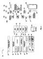
- FIG. 1Ais a general block diagram of an asset tracking system according to an exemplary embodiment.
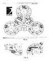
- FIGS. 1B-1Dare illustrations of various configurations utilizing asset tags, reference tags and gateway tags to establish a wireless mesh network for asset tracking.
- FIG. 2is a front view of a tag unit for use in the asset tracking system illustrated in FIG. 1 according to another exemplary embodiment.
- FIG. 3is a flow diagram of a security feature utilizing a low frequency proximity sensor for use in the asset tracking system illustrated in FIG. 1 according to another exemplary embodiment.
- FIG. 4is a block diagram of an overview of an asset tracking system according to another exemplary embodiment.
- FIG. 5is a front view of a positioning input point for use in an asset tracking system as illustrated in FIG. 1 according to another exemplary embodiment.
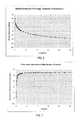
- FIG. 6is a graph of energy distribution vs. distance according to another exemplary embodiment.
- FIG. 7is a first order derivative of the distribution function illustrated in FIG. 6 according to another exemplary embodiment.
- FIGS. 8 and 9are histograms that represent geometric analysis of an access point for use in an asset tracking system as illustrated in FIG. 1 according to another exemplary embodiment.
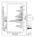
- FIG. 10is a graph of a histogram, used as an example, according to another exemplary embodiment.
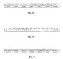
- FIGS. 11 thru 17are tables of data used for access point mapping for use in an asset tracking system according to further exemplary embodiments.
- FIG. 18is a table of additional exemplary set data used for access point location determination in an asset tracking system according to further exemplary embodiments.
- FIG. 19is a table showing examples of access points being positioned near by or between other access points according to another exemplary embodiment.
- FIG. 20is a graphical representation showing examples of access points being positioned near by or between other access points according to another exemplary embodiment.
- FIG. 21is a map showing examples of access points being positioned near by or between other access points according to another exemplary embodiment.
- FIG. 22is a table showing examples of access points being positioned near by or between other access points according to another exemplary embodiment.
- FIG. 23is a graphical representation showing examples of access points being positioned near by or between other access points according to another exemplary embodiment.
- FIG. 24is a map showing examples of access points being positioned near by or between other access points according to another exemplary embodiment.
- FIG. 25is the front view of a PDA, an example of a user interface, for use in an asset tracking system illustrated in FIG. 1 according to another exemplary embodiment.
- FIG. 26is a screen shot of an information center for use in an asset tracking system illustrated in FIG. 1 according to another exemplary embodiment.
- FIGS. 27 thru 29are examples of title bar configurations as used in an information center illustrated in FIG. 26 according to another exemplary embodiment.
- FIG. 30is a screen shot of a rule set window to be used in information center illustrated in FIG. 26 according to another exemplary embodiment.
- FIG. 31is a screen shot of an alerts window to be used in an information center illustrated in FIG. 26 according to another exemplary embodiment.
- FIG. 32is a screen shot of a select items window to be used in an information center illustrated in FIG. 26 according to another exemplary embodiment.
- FIG. 33 and FIG. 34are screen shots background color being utilized in a tree to alert the user to messages to be used in an information center illustrated in FIG. 26 according to further exemplary embodiments.
- FIG. 35is a screen shot of property windows for use in an information center illustrated in FIG. 26 according to an exemplary embodiment.
- FIG. 36is a screen shot of search results displayed as text in table format to be used in an information center illustrated in FIG. 26 , according to an exemplary embodiment.
- FIG. 37 and FIG. 38are screen shots of search results displayed as chart windows to be used in the information center illustrated in FIG. 26 , according to another exemplary embodiments.
- FIG. 39 and FIG. 40are additional examples of screen shot search results displayed as chart windows to be used in an information center as illustrated in FIG. 26 according to further exemplary embodiments.
- FIG. 41 and FIG. 42are screen shots of floor plan windows to be used in information center as illustrated in FIG. 26 according to further exemplary embodiments.
- FIG. 43is a screen shot of a watch alerts window to be used in an information center as illustrated in FIG. 26 according to another exemplary embodiment.
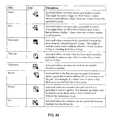
- FIG. 44is a screen shot of a table of watch alert icons to be used in information center as illustrated in FIG. 26 according to another exemplary embodiment.
- FIG. 45is a screen shot of a watch resources window to be used in an information center as illustrated in FIG. 26 according to another exemplary embodiment.
- FIG. 46is a screen shot of a watch locations window to be used in an information center as illustrated in FIG. 26 according to another exemplary embodiment.
- FIG. 47 and FIG. 48are screen shots of watch windows to be used in information center as illustrated in FIG. 26 according to further exemplary embodiments.
- FIG. 49is an example of a vector analysis used for access point location determination in an asset tracking system according to another exemplary embodiment.
- asset tracking system 10is illustrated according to an exemplary embodiment.
- asset tracking system 10can be used to track people or assets.
- Asset tracking system 10has been configured to use IEEE 802.11b wireless networking standard. Employing this standard, advantageously allows asset tracking system 10 to utilize an existing wireless infrastructure 19 , however, other wireless standards could be employed without departing from the scope of the invention.
- asset tracking system 10includes one or more transmitting points, such as wireless access points 16 and one or more tag units 18 .
- Access points 16broadcast wireless signals, over existing 802.11b wireless infrastructure 19 , that can be received by tag units 18 .
- Tag units 18measure and collect relative signal strengths of broadcasted probe response signals from multiple transmitting points, such as access points 16 .
- Tag units 18connect with wireless access point 16 and communicate the collected signal strengths to a processing station, such as a server hosting positioning service 14 through local area network (LAN) 17 .
- Positioning service 14may be a PC, laptop or server, that includes one or more software suites and serves as a positioning/location engine for tag units 18 and transmitting points.
- Positioning service 14acts as a location engine and determines the location of tag unit 18 based on calibration data collected during initial installation, historical movements of tag unit 18 , and statistical analysis.
- the location of the assetis published to end user applications and preserved in a database for future reporting and analysis.
- Users 11can view the location data on end-user devices, such as workstation 12 , PDA's 13 , and laptops 15 .
- the location datacan be used with a software kit for integration with third party applications, such as warehouse management and facility information systems.
- tag unit 18may be configured to perform the analysis of the positioning service 14 as described below and act as a self locating location engine.
- the location, as determined by tag unit 18is delivered to a database for reporting and analysis and published to end user applications.
- asset tracking system 10comprises client workstation(s) 12 which receives data associated with signal strengths between wireless access points 16 and tag unit 18 .
- Workstation 12analyzes the data associated with a number of transmitting access points 16 and determines the locations of tag unit 18 .
- positioning service 14determines the location of tag unit 18 based on the following: calibration data collected during initial installation; historical movements of tag unit 18 ; and statistical analysis, or any combination thereof.
- positioning service 14does not necessarily need to use calibration data collected during installation for calculating locations, instead, it can make use of the dynamic sample points from each reference point (e.g., transmitting points and tag units) to perform location calculations.
- tag unit 18is a small battery powered wireless transceiver which collects probe responses from transmitting points, such as standard wireless access points (AP) 16 , positioning input points (PIP) 30 and from other tag types discussed below.
- APstandard wireless access points
- PIPpositioning input points
- tag unit 18When tag unit 18 is configured to perform the functions of asset tag 18 a it may be attached to various assets and medical equipment for real-time locating and asset management.
- Tag unit 18(referring to all types of tags) may be configured to be compatible with IEEE 802.11b wireless communication systems and designed for minimal bandwidth, enabling user 11 to utilize existing wireless local area network (WLAN) infrastructure 19 .
- Tag unit 18is managed through a mobile management resource management software.
- tag units 18may consist of three different types of tags, including: an asset tag 18 a , a reference tag 18 b and a gateway tag 18 c . Combinations of these tags may be configured in various arrangements to form wireless mesh networks that communicate with a processing station, such as positioning service 14 , via a network connection for determining the location of anyone of the tags.
- Asset tag 18 aoperates by collecting information about its surroundings via a wireless connection, such as 802.11a/b/g. Asset tag 18 a conveys this information to another device capable of determining the location of asset tag 18 a based on the collected information.
- asset tag 18 asends probe request messages to transmitting points, such as wireless access point 16 and reference tag 18 b , in an 802.11 network by.
- Reference tag 18 b and/or AP 16respond with probe response messages from which asset tag 18 a determines the received signal strength indication (RSSI) of each response signal.
- RSSIreceived signal strength indication
- Asset tag 18 acollects the RSSI information and communicates the information to either AP 16 or reference tag 18 b .
- the information itis eventually communicated to a processing station, such as positioning service 14 , that is capable of determining the location of asset tag 18 a from the collected data.
- asset tag 18 amay be configured to collect, use and send time of flight (TOF) information to facilitate location of asset tag 18 a .
- TOFtime of flight
- reference tags 18 bincluding gateway tags 18 c
- asset tag 18 acan determine a rudimentary TOF for each message sent. The message with the lowest TOF is likely the most direct path between reference tag 18 b and asset tag 18 a .
- reference tag 18 btimestamps its message with an incremented value.
- Asset tag 18 atimestamps the message with its own incremented value when the message is received.
- Asset tag 18 alooks at the difference between each of the time stamps of the messages received from reference tag 18 b and determines which spent the least amount of time traveling to asset tag 18 a . Once asset tag 18 a has found the signal with the shortest transmission time, asset tag 18 a may then determine that signal's RSSI and send the RSSI information to positioning service 14 .
- Asset tag 18 a , reference tag 18 b and gateway tag 18 cideally use the same circuit board and firmware to create a tag that can be tracked, a tag that can serve as a fixed reference and a tag that can act as a gateway to a network, such as LAN 17 or a WLAN.
- Asset tag 18 a , reference tag 18 b and gateway tag 18 care configured to communicate with one another to form a wireless mesh network as shown in FIGS. 1B-1D .
- Reference tag 18 bis configured to act as a signal source, asset tag 18 a collects the signals from reference tag 18 b and the collected signals are sent, via the wireless network to a processing station, such as positioning service 14 , that analyses the signals from the reference tags to determine the position of asset tag 18 a.
- a site for tracking assetscan be created using a series of reference tags 18 b that are meshed together as in FIGS. 1B-1D .
- asset tag 18 awill transmit packets of collected information to reference tag 18 b , which may then transmit the collected packets to another reference tag 18 b and so on until the packets are delivered to the network, such as LAN 17 , and then to positioning service 14 .
- the packetsmay be delivered to the network via a wired or wireless connection from gateway tag 18 c , as in FIG. 1B , access point 16 , as in FIG. 1C , or a combination of the two, as in FIG. 1D .
- Gateway tag 18 coperates much like reference tag 18 b with the additional feature of providing a transport mechanism for delivering the collected packets of information to another medium, such as Ethernet.
- Gateway tag 18 c and reference tags 18 bcan communicate with one another to form a wireless mesh network, as in FIGS. 1B-1D .
- Asset tag 18 acollects and sends packets of information to reference tag 18 b , which repeats the information packets to another reference tag 18 b until it is finally delivered to gateway tag 18 c .
- Gateway tag 18 cconveys the information packets to another supported media.
- Reference tags 18 b and/or gateway tags 18 ccan be used in lieu of a wireless communications network, as in FIG. 1B .
- the reference tags 18 bcan be used 18 a to send information packets from asset tag 18 a to gateway tag 18 c , thereby allowing asset tag 18 a to communicate with a processing station, such as positioning service 14 .
- This deployment modelallows asset tracking in areas that do not have a wireless communications infrastructure.
- reference tags 18 b and/or gateway tags 18 ccan be used to expand the coverage area of a wireless network or to increase the density of coverage within a coverage area.
- FIGS. 1B-1Dshow the coverage area devices in communication with positioning service 14 .
- Position service 14may be located on site or may be located remotely with respect to the coverage area.
- gateway tag 18 cmay use any type of network protocol or network technology, wired or wireless, to communicate with positioning service 14 .
- gateway tag 18 cmay be configured to communicate using generic packet radio service (GPRS), worldwide interoperability for microwave access (WiMAX) or any other wide area network (WAN). Gateway tag 18 c may also be configured to communicate with the processing station using a radio access network (RAN).
- GPRSgeneric packet radio service
- WiMAXworldwide interoperability for microwave access
- WANwide area network
- Gateway tag 18 cmay also be configured to communicate with the processing station using a radio access network (RAN).
- RANradio access network
- asset tag 18 awakes up periodically and sends probe requests to all AP 16 , PIP 30 , and other tag types in the vicinity.
- AP 16 , PIP 30 and the other tags typessend probe responses from which asset tag 18 a collects all RSSI (received signal strength indication) values and associates with specific AP 16 , PIP 30 and other tag types and transmits the RSSI position information to positioning service 14 on local area network (LAN) 17 .
- Positioning service 14determines the location of asset tag 18 a with respect to AP 16 , PIP 30 and the other tag types.
- PIP 30can be similar to AP 16 and provides responses to asset tag 18 a as described in more detail below.
- asset tag 18 atransmits a signal to a transmitting point (e.g., AP 16 , reference tag 18 b , gateway tag 18 c and/or PIP 30 ) and the transmitting point determines the RSSI for each signal, and collects the RSSI information and transmits the RSSI information to positioning service 14 .
- a transmitting pointe.g., AP 16 , reference tag 18 b , gateway tag 18 c and/or PIP 30
- asset tag 18 aTo associate a transmitting point (AP 16 , PIP 30 , reference tag 18 b and/or gateway tag 18 c ), asset tag 18 a must first issue an association request. The transmitting point then sends out an association response, which notifies tags 18 of the association ID. Once asset tag 18 a is associated, it can send out a packet containing all of the RSSI values collected. Association requests may also be issued by the other types of tags in order to form associations with other location system devices (e.g., AP 16 , PIP 30 , asset tag 18 a , reference tag 18 b , and/or gateway tag 18 c ).
- tag unit 18will refer generally to tags, which may include asset tag 18 a , reference tag 18 b and gateway tag 18 c.
- tag unit 18determines delivery location of the packet to positioning service 14 by performing an address resolution protocol (ARP) frame with the server's destination IP address and a broadcast media access control (MAC) address.
- ARPaddress resolution protocol
- MACbroadcast media access control
- a switchforwards this broadcast to all ports, including one attached to a router.
- a routerrecognizing that it can reach the server's network, will send an ARP response frame with its own MAC address as a destination MAC address tag unit 18 can use. Association with PIP 30 is not necessary.
- Tag unit 18is able to distinguish between PIP 30 and standard AP 16 by the organizational unique identifier (OUI) at the header of the MAC address.
- UAIorganizational unique identifier
- Tag unit 18may be a complete, self powered electronic assembly consisting of a printed circuit board, an 802.11 radio MAC/Baseband, 2.4 GHz antenna for transmitting and receiving, and a lithium battery, sealed in a plastic housing.
- a battery powering tag unit 18is designed to have a shelf life of 5 years and maintain power up to 3 years once initialized.
- Tag unit 18employs an on-board motion detector and low power management system to extend or maximize battery life. Should tag unit 18 become stationary, the battery powers down, hence extending battery life. Tag unit 18 can transmit low-battery alerts when replacement is eminent.
- reference tags 18 b and gateway tags 18 ccan also synchronize with each other and asset tag 18 a to conserve battery life.
- the first reference tag to be activatedmay send a pulse signal on a periodic interval.
- Other reference and gateway tags that become activewill detect the pulse and begin sending their signals just slightly offset from the pulse.
- asset tag 18 awakes up, it waits for a signal and then stays awake just long enough to receive all the signals from the reference and/or gateway tags.
- Asset tag 18 amay be configured to then awake at the same periodic interval as the reference tags and gateway tags, thereby maximizing it sleeping time and conserving battery life.
- asset tag 18 awakes up when it detects motion. After waking up from motion detection, it waits for a signal and then stays awake just long enough to receive all the signals from the reference and/or gateway tags.
- tag units 18are software configurable so that any single tag unit may be configured or reconfigured to act as either an asset tag, a reference tag or a gateway tag.
- Software configurable tag units 18provide maximum flexibility for adapting to new coverage areas and new coverage area configurations.
- the physical size of tag unit 18is less than 2′′ high by 1.5′′ wide by 1′′ deep, with a weight of less than one ounce.
- Tag unit 18comprises a welded waterproof, chemical-proof case and may be mounted to asset by adhesive, tie wrap, lanyard, or clip.
- Tag unit 18withstands temperatures from 0 to 120 degrees Fahrenheit and non-condensing humidity from 0 to 95%.
- Tag unit 18is IEEE 802.11b and FCC compliant, and is capable of both high frequency (2.4 GHz) and low frequency (262 kHz) transmission. However, all tags do not necessarily have to come in the same physical form factor.
- Various tag units 18may be different shapes, sizes and enclosures and they may be powered externally or battery powered.
- Tag units 18may accept different battery types, or be rechargeable and have a docking station designed for battery recharging.
- tag unit 18includes a tamper detection security feature, tamper contacts, that prevents theft and loss of equipment by causing an alert when tag unit 18 is removed from the asset or other fixed location (depending on the tag type).
- the contactsare connected to an adhesive pad that is used to attach tag unit 18 to the asset or fixed location. When tag unit 18 is removed from the asset or fixed location, the contacts in the adhesive pad break and come free from tag unit 18 and a tamper is detected.
- U.S. Pat. No. 7,098,792 assigned to the assignee of the present applicationis herein incorporated in its entirety by reference and discloses tamper proof features.
- asset tag 18 aincorporates low frequency transmitter 20 that can be configured to stop equipment or people from leaving the facility or area of the facility.
- the low frequency IDis programmed into asset tag 18 a during initial configuration at the facility.
- Tag configuration softwareselects the next unused low frequency ID and associates with the MAC ID of tag unit 18 .
- the low frequency transmittermay incorporate unique low frequency ID's in order to use the receive data from portal receivers to determine asset tag 18 a floor to floor movement. The movements can be used by the positioning algorithms to place asset tag 18 a on the proper floor.
- tag configuration softwareis used to provide a means of updating tag unit 18 configuration parameters in the facility over a wireless network.
- Tag unit 18is shipped with a default service set identifier (SSID). Once the tamper contacts are shorted, tag unit 18 associates to the AP with the default SSID begins looking for a server packet from AP 16 containing new configuration parameters. If a server packet is not recognized within a designated time frame, tag unit 18 goes back into low power sleep mode.
- AP 16 or PIP 30 with an SSID connected to a laptop or PC with administrative softwarecan be utilized to perform the initial configuration. Embodiments of PIP 30 are discussed with reference to the FIGURES.
- tag unit 18can also be configured through a wireless network. Upon doing a collection, tag unit 18 listens for a server packet that is directed to its own MAC address. When a server packet is received by tag unit 18 , tag unit 18 updates its internal parameters and sends an acknowledgement during its next positioning transmission.
- VLFvery low frequency
- U.S. Pat. No. 5,793,290discloses a door controller and is incorporated herein by reference in its entirety and assigned to the assignee of the present application.
- Magnetic door locksare often used in conjunction with asset tag 18 a as a security system for monitoring the movement of persons in secured areas.
- the security systemis based on a combination of a dual transmitting asset tag 18 a attached to an asset and a plurality of receivers appropriately located within secured areas.
- Proximity sensor 20receives the VLF 262 kHz security and proximity signal transmitted from asset tag 18 a when it comes within range of proximity sensor 20 .
- Information contained in the low frequency signalsis communicated by door controller 22 to positioning service 14 and is used to improve the precision of the location algorithms and to enhance the overall security of asset tracking system 10 .
- proximity sensor 20information is sent to positioning service 14 . Given the VLF range is very defined and finite, a proximity message received for asset tag 18 a is given the highest priority in terms of location delivered to the user. The location accuracy of asset tag 18 a is improved due to a limited communication range of the VLF signal.
- asset tracking system 10can lock a door.
- a messageis sent from door controller 22 to a mobile resource manager via an RS-485 to wireless converter 24 .
- the mobile resource managersends disallowed resource types to door controller 22 so as to control access of resource types.
- door controller 22checks the list of disallowed resource types provided by the mobile resource manager. If a resource type is not allowed, magnetic door lock 26 locks a door.
- Door controller 22sends an alarm event to the mobile resource manager as necessary. This operation increases the security capability on the premises and improves wander management and security capabilities of asset tracking system 10 .
- VLF proximity sensor 20can support a unique 16-bit tag identifier.
- VLF transmittersare used for portal security and improved proximity location as they must be read from within a very defined, repeatable, and consistent distance of 4 to 8 feet. This distance is desired for portal security and improved proximity location. Higher frequency signals for portal security and proximity location become less desirable as they are more subject to interference and are less consistent in read range accuracy.
- a positioning input point (PIP) 30is an optional component to asset tracking system 10 .
- PIP 30is used to improve positioning performance and to extend the communication coverage tag unit 18 where existing wireless coverage is intermittent or inadequate.
- PIP 30can be configured to broadcast 802.11b compliant beacons to be used by tag unit 18 to improve performance by providing additional RSSI measurements.
- PIP 30can also be configured to transmit other types of beacons.
- tag typessuch as reference tag 18 b and gateway tag 18 c may be employed to extend communication coverage or enhance reliability in the current coverage area.
- PIP 30can also connect as a client station to an existing 802.11b wireless network to provide a wireless backhaul to an existing 802.11b network when a wired Ethernet connection is not needed.
- PIP 30is not a fully functional 802.11b access point 16 in that it does not allow other 802.11 devices to associate. Consequently, PIP 30 does not relay any data or communications other than tag unit 18 information.
- PIP 30monitors for tag unit 18 association requests when not transmitting to look for tag unit 18 position updates. PIP 30 sends out an association response, which notifies tag unit 18 of the association ID and returns back to receive mode to collect the new tag unit 18 position update.
- PIP 30is a complete AC or POE powered electronic assembly consisting of a printed circuit board, 802.11 radio, MAC/Baseband, and a 2.4 GHz antenna 32 for transmit and receive, in a plastic housing.
- PIP 30can operate in a promiscuous PIP mode.
- PIPs 30are used in the asset tracking system to provide additional signal sources in asset tracking systems that do not have adequate access point 16 coverage for location based systems.
- PIPs 30are also used to improve the location accuracy in areas that need further distinction due to the AP 16 layout or other factors.
- PIP 30 in promiscuous mode in an asset tracking systemcan have the ability to be used in commissioning or debugging of the asset tracking system.
- PIP 30 in promiscuous modeis in continuous receive mode and does not restrict packets into classes. It is essentially a wireless packet sniffer that allows debugging of all packets present in the medium. Packets seen by PIP 30 are not only devices that are part of the asset tracking system but all packets present in the medium.
- PIP 30 in promiscuous modecan also be used to flag the software of tag units 18 that are not behaving accordingly on the network for debugging purposes.
- a PIP 30 in promiscuous modecan monitor packets from other wireless devices such that PIP 30 can provide RSSI values from various packets of other wireless devices.
- PIP 30can send MAC address of wireless devices along with RSSI values from the various packets seen to the location server. This allows for tracking of other devices without needing to load an asset tracking wireless client onto devices such as laptops, VoIP phones, PDA's, etc.
- the softwarecan also be configured to provide a feature of auto-enrolling all MAC addresses seen by PIP 30 to aid in entering all devices onto the location system.
- PIP 30 , reference tag 18 b and gateway tag 18 ccan provide the ability to obtain major power saving modes for asset tag 18 a in a system.
- Asset tag 18 acan be configured to collect RSSI from all PIP 30 , reference tag 18 b , gateway tag 18 c and AP 16 in the vicinity of asset tag 18 a as in normal operation. In normal operation, asset tag 18 a probes all PIPs 30 , reference tags 18 b , gateway tags 18 c and APs 16 and associates to the strongest PIP 30 , reference tag 18 b , gateway tag 18 c or AP 16 from the probes performed.
- Asset tag 18 acan perform ARP to determine the necessary destination MAC address to deliver the location packet to the location engine/server.
- the asset tag 18 acan be configured to force the delivery of the location packet through the PIP 30 , reference tags 18 b , gateway tags 18 c and not the AP 16 . Since PIP 30 , reference tags 18 b and gateway tags 18 c can perform the ARP for asset tag 18 a and since PIP 30 , reference tags 18 b and gateway tags 18 c can allow asset tag 18 a the ability to not force an association for tags, there is significant power savings for the tag.
- the tagknows a PIP is present if it receives a probe response from an OUI.
- gateway tag 18 cmay be configured to connect to positioning service 14 through either a wired or wireless connection.
- gateway tag 18 cmay be configured to connect to AP 16 through a wired or wireless connection for communicating packet information to positioning service 14 .
- Reference tags 18 bare configured to communicate with asset tag 18 a for the generation of RSSI information and the transmission of RSSI information to positioning service 14 .
- the transmission of RSSI information from reference tag 18 b to positioning service 14may be accomplished via gateway tag 18 c and/or AP 16 . It is important to note that the tags are capable of being configured and reconfigured. Thus, any of the tag types may be reconfigured to perform the functions of the other tag types.
- reference tag 18 b and gateway tag 18 cmay be configured, or reconfigured, to perform the same functions as asset tag 18 a
- implementing Circular Polarized (CP) antennas in the PIPprovides significant improvements in RSSI stability in harsh environments. RSSI values can change significantly due to multi-path, orientation, polarization, fading, and other environmental factors. Signals from linear polarized antennas can vary significantly due to the factors listed above.
- PIPuses directional circular polarized antennas to improve the location accuracy.
- the use of directional antennasprovides significant improvements to the accuracy of the location algorithm by the simple fact that it gives you a better idea of where the tag is located.
- PIP 30is recognized as a client on a network. As tag unit 18 communicates with PIP 30 , PIP 30 transfers the position information of tag unit 18 to a network. PIP 30 can accomplish this by Ethernet connection or a wireless connection to local AP 16 . Therefore tag unit 18 is not in constant communication with the wireless network. This configuration provides power savings for the battery in tag unit 18 .
- PIP 30can be built into a wireless pull-cord, smoke alarm, etc. for room level accuracy.
- PIP 30 with a low frequency at bedside for improved location accuracycan aid the facility in customer charges. For example, a hospital knows the exact IV pump and other equipment is situated at what bed location and for what length of time for billing purposes.
- PIP 30has status LED indicators (e.g. LED 34 , 36 , 38 ).
- a power LED 34 of solid redindicates AC or POE power present.
- a wireless link LED 36shows a link is present via wireless 802.11 network 19 (illustrated in FIG. 1 ) to service engine.
- Solid greenindicates a wireless link is established. Flashing green indicates an asset packet was received via a wireless link.
- Ethernet link LED 38shows a link is present via Ethernet to a service engine.
- Solid yellowindicates an Ethernet link is established and flashing yellow indicates an asset packet was received via Ethernet link.
- An exemplary embodiment of a PIP 30is illustrated in FIG. 5 .
- PIP 30built into the circuitry of PIP 30 , is the ability to sense noise in the 2.4 GHz spectrum.
- 802.11 wireless network 19is divided into eleven channels within the United States.
- PIP 30looks at all eleven channels and senses any obstruction in the form of noise that may interfere with asset tracking system 10 or other equipment located within the facility.
- Positioning service 14relays this information to user 11 .
- a third party with monitoring abilitycan be used to incorporate a preventative maintenance program for asset tracking system 10 and related components.
- positioning service 14contains algorithms that determine the position of tag unit 18 .
- Positioning service 14receives messages from tag unit 18 containing the RSSI values of the AP 16 in an area. Higher RSSI values correspond to stronger signals.
- Statistical and heuristic algorithmsare applied to data and a position of tag unit 18 is determined and published to user 11 .
- Algorithm concepts that are included in an analysiscan be the following or any combination thereof: histograms; static analysis; vector analysis; and geometric center analysis.
- tag unit 18is configured to apply algorithms to determine its own position (e.g., self locate).
- tag unit 18transmits its location, which is eventually delivered to one or more of: positioning service 14 , alerter service 21 , recorder service 23 , extractor service 25 , configurator service 53 and SQL server 51 . Once the one or more services are performed, the location of tag unit 18 is delivered to information center 40 . Alternatively, the location of tag unit 18 may bypass the various services and be delivered directly to information center 40 .
- alerter service 21can receive location messages from positioning service 14 and analyze them against alert rules.
- the rulescan be defined, stating when an alert should occur, based on tag unit 18 and location combinations. Rules can be created using administrator center 41 .
- recorder service 23can subscribe to alerter service 21 and positioning service 14 .
- Recorder service 23can save changes in data received to an SQL server 51 . Data can only be recorded when changes occur.
- configurator service 53can provide services, hardware, and applications with necessary configuration information stored in a central database.
- Configurator service 53can create initial communication settings to allow services and clients to communicate.
- Configurator service 53can also allow scalability for asset tracking system 10 by brokering information requests.
- Configurator service 53can also provide interfaces for connecting to a database and retrieving information.
- extractor service 25can be queried to retrieve data recorded by recorder service 23 .
- Datacan be used by information center 40 and PC/Mobile WebForms 27 to provide tracking functions and generate custom reports.
- information center 40is a user interface for asset tracking system 10 .
- Information center 40can watch resources 29 , watch alerts 31 , view reports, 33 , create utilization charts, view floor plans, 35 , and monitor real-time data pertaining locations 37 .
- administrator center 41can be a primary user interface for configuring data into asset tracking system 10 .
- Administrator center 41consists of several modules that allow users tag unit entry 39 , alert entry 43 , trigger entry 45 , resource entry, location entry, access point entry 47 , etc. Administrator center can also be a primary tool used for calibration 49 .
- Information center 40 and positioning service 14may be incorporated into one station, such as a PC or server, or a configuration of multiple PCs or servers.
- the station incorporating information center 40 and positioning service 14may be remotely located with respect to the coverage area or may be on site.
- Information center 40 and positioning service 14may be separate stations and either one may be remotely located with respect to the coverage area or located on site.
- the other servicese.g., alerter service 21 , recorder service 23 , extractor service 25 , and configurator service 53
- SQL server 51may be incorporated into a single station with the information center 40 or may form one or more stations at one or more locations in various configurations.
- FIGS. 6-49generally refers to access point (AP) 16
- other types of transmitting pointsmay substituted, including PIP 30 , reference tag 18 b and gateway tag 18 c .
- asset tag 18 amay utilize the algorithms and functions below to determine its own location with respect to the various reference points in the coverage area (e.g., AP 16 , PIP 30 , reference tag 18 b or gateway tag 18 c ).
- processing stationcan use dynamic sample points obtained from reference points and asset tags for location calculation.
- the first stepis to collect calibration data at given locations.
- One calibration data fileis a set of a number of RSSI samples.
- the recommended number, Nis 2000; 500 or 20 being acceptable for a rapid test.
- Histogramscan be created from calibration data.
- the histogramis a graph of a probability distribution function vs. the RSSI value.
- the minimum RSSI valueis 25, and the maximum RSSI value is 75.
- This calibration datais within the range of (25,75).
- Modeis the term used for an RSSI value with the highest number of samples, or the highest probability.
- the RSSI value of 50is the mode.
- the histogramcan be treated as an N dimensional vector. Any RSSI value in the range of (25,75) is possible with the mode value as the highest probability.
- the function of a positioning algorithmis to find likelihood between the testing sample and all calibration histograms. Because a histogram is a graph of the probability distribution function vs. the RSSI value, or a range of energy, it is required to take Mnumber samples.
- the Mnumber, or testing samplescan be treated as an M dimensional vector, a sub vector of a calibration histogram vectors. Generally, M is much less than N. (A preferred M value is 15 or 20.)
- the definition of normalized histogramis:
- the first step in the analysisis to define RSSI.
- the RSSIis related to the value of the amount of energy present in the dBm (dB milliwatts) scale.
- the mathematical definition of RSSIis a mathematical definition of the mathematical definition of RSSI:
- RSSI ⁇ ( x )10 ⁇ log 10 ⁇ ( I ⁇ ( x ) I ⁇ ( 0 ) ) ( 1 )
- RSSI(x)is the value measured by PDA 13 or other wireless devices. It is a function of distance x, where I(x) is the amount of energy at position x, and I( 0 ) is the amount of energy at position 0 , the source of the energy.
- FIG. 6illustrates energy distribution vs. distance. The amount of energy is proportional to the reciprocal of x 2 , and I( 0 ) is a constant of AP 16 :
- RSSI ⁇ ( x )- 20 ⁇ ln ⁇ ⁇ x ln ⁇ ⁇ 10 - A ( 4 ) Then, the derivative of RSSI(x) as illustrated in FIG. 7 :
- the effective radius of AP 16is approximately 5 meters when the difference between the RSSI(x) values is about 5 dBm between the two locations and the distance between these two locations is about 3 meters.
- the next step of the analysisis to define the roles of AP 16 and tag unit 18 .
- the signal generator, AP 16transmits a microwave signal with a frequency band of 2.4 GHz.
- the signal receiver, tag unit 18 or end user devicereceives the microwave signal.
- the strength of the signalis varied by the distance that the signal travels to the receiver. Therefore, the smaller the distance between AP 16 and tag unit 18 , the stronger the signal that the tag unit 18 receives.
- the geometric set up of AP 16is analyzed. Assume position one is located at x 1 , and position two is located at x 2 . AP 16 is located on a line that extends from x 1 and x, to x 3 . Equation (8) determined that AP 16 is approximately five meters away from the middle point of the two positions. Therefore, AP 16 can provide calibration and histogram data to distinguish these two positions within the three meter range. However, should AP 16 be located on a perpendicular bisector line of x 1 and x 2 , as illustrated in FIG. 9 , then AP 16 cannot provide any distinguishable information about position one, or x 1 , and position two, or x 2 .
- AP 16should not be placed symmetrical to target positions.
- the location of AP 16may not be able to be determined, but AP 16 that is symmetrical to some positions may be filtered out as a potential location.
- PIP 30may be added to further determine the location.
- the required number of access points 16 to locate tag unit 18becomes:
- the recommended Effective Radiusis less than 10 meters.
- a general positioning algorithmis analyzed.
- more than five, or a set, of access points 16may see tag unit 18 .
- every access point 16takes a fingerprint (histogram) of this location.
- another set of access points 16may see tag unit 18 .
- the fingerprint or histogrammay be different in both cases.
- the two sets of access points 16may have a common sub set that contain the same access points 16 , or they may contain different access points 16 .
- a histogramas illustrated in FIG. 10 , normally contains more than one thousand data points.
- a target tag unit 18receives ten testing RSSI data from each access point 16 at each location. The positioning algorithm tries to find the highest number of matches between the testing RSSI data and the calibration histogram data.
- pointsAfter transmitting points (reference tags 18 b , gateway tags 18 c , AP 16 and PIP 30 are calibrated), they may be configured to continuously or periodically monitor their respective environments.
- the affected signal sourceWhen changes in the environment affect signals being transmitted and received to and from other devices (e.g., other AP 16 , PIP 30 , reference tags 18 b and gateway tags 18 c ) the affected signal source notifies the processing station, such as positioning service 14 , and the algorithms are dynamically adjusted to account for the changes.
- Changes that might affect signalsinclude, but are not limited to: new objects, structures or barriers within the coverage area, the addition or removal of devices configured to connect with the location system, addition of devices not configured to connect with the location system within the coverage area that transmit signals at frequencies that interfere with the system, changes in weather, etc.
- the purpose of developing the algorithmis due to limitations contained within the facility. Rooms, doors, windows, walls, equipment, etc. attenuate a radio frequency signal received by tag unit 18 . Therefore, the signal is no longer a function of only distance, but the signal's energy distribution within the facility.
- Tag unit 18can access one set of access points 16 at one position, another set of access points 16 at another location and, in some positions, tag unit 18 can access the same set of access points 16 . Therefore, if a map can be made of access points 16 in the system, then the correct position of tag unit 18 can be determined by comparing the tag unit 18 exemplary set data with access point mapping.
- an assumptionis made that every location has unique access point mapping.
- the target position of tag unit 18may then be found.
- tag unit 18may have the same access point mapping.
- PIP 30may be added to further pinpoint the location.
- an access point mapping algorithmis created.
- Access point mappingcould be a filter that eliminates locations far away from the target location.
- Access point mappingis created during system initialization period.
- the rows, N,represent locations, and the columns, M, represent access points 16 (AP).
- the last columnis the bitmap values, or vectors, of each location.
- Each individual APrepresents a component of the vector. The order of the component is random.
- the target datais collected and an AP vector is generated of the location as illustrated in FIG. 12 .
- the order of the AP in the vectoris the same as on the map.
- the tag vectoris then put into a logical operation, or XOR, at each vector location. If one XOR result has a minimum number of components, then this location is correct. If there are two or more XOR results with a minimum number of components, then it becomes necessary to find the location's access point vector that has the maximum number of components. If only one location of AP vector has the maximum number of components, then this location is correct. If there are multiple locations with the same maximum number of components, then these locations are candidates that need to be analyzed through other algorithms.
- FIG. 13Illustrated in FIG. 13 , is the result of the tag target AP vector XOR with the coordinating access point mapping vector.
- the locations having the minimum number of components in their XOR resultscould be the target location for tag unit 18 . Therefore, the access point mapping vector of location 5 and 6 access point vectors are considered. All other locations are filtered out.
- the tag's vectoris more similar to with location 5 than location 6 . Therefore 5 is determined to be the final location.
- FIG. 14is another testing tag target AP vector (0x07f0).
- FIG. 15shows the result of the tag target AO vector XOR with each AP mapping vector. There are zero components in the location 0 , 2 , 3 , and 4 . These four locations have the same AP mapping vector, so they are all candidates for further analysis.
- FIG. 16is another testing tag target AP vector (0x03f9).
- FIG. 17shows the result of the tag target AP vector XOR with each AP mapping vector. Only location 5 has one component, therefore location 5 is determined to be the final answer.
- another phase of data analysis for the calibration testing datais to verify another type of testing tag data.
- the electromagnetically microwave signalsare attenuated in conjunction with
- a GPSin free space, can determine a target position of tag unit 18 successfully by the triangulation with variables of altitude, latitude, longitude, and time.
- the microwaveperforms totally different. Because of multi-path interference, the signals are combined by superposition. Therefore variables must be determined to distinguish one position from others and a model must be established to fit the system.
- the only guidelineis which zone owns the highest location probability judged by the five AP histograms.
- the resultsare then ranked by probabilities of the zones.
- facility assetscan be frequently moved about the facility for use in other areas on an as needed basis.
- Tag unit 18can be mounted on each asset. As assets are moved from room to room or floor to floor, wing to wing, etc, different areas of the facility can have varying wireless signal strengths. In order for asset tracking system 10 to locate a tag, a calibration of facility areas is performed.
- a vector analysiscan be used to determine varying signal strengths throughout the facility.
- a vector analysiscan be analyzed to determine a location of tag unit 18 .
- the V designation with subscriptis an assigned area within a facility. The area can be a room, wing, zone, etc.
- tag unit 18collects signals within these areas.
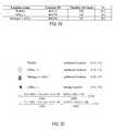
- the vectorsrepresent the signal strength readings taken from the samples. Signal strength readings are then compared with previous samples taken. If a match is made, the asset location is determined. In the example in FIG. 49 , five samples have been read. These samples and their corresponding readings are represented by vectors.
- the first sample 43received 3 votes as the preferred signal
- the second sample 45received 4 votes as the preferred signal
- the third sample 47received five votes as the preferred signal
- the fourth sample 49received 2 votes as the preferred signal
- the fifth sample 50received one vote as the preferred signal. Therefore 47 , the signal with the highest number of votes translates to the strongest signal and becomes the location of tag unit 18 that is entered into the database.
- the location of tag unit 18is also recorded in a database for future report generation.
- all calibrated locationshave their coordinates on the map.
- a positioning displayis based on the coordinates of the calibrated locations.
- the probability of the calculated locationis greater than 90%.
- a calculated position in a histogram of higher than 90%is determined “in”. If the location does not return a 90% probability, then it may be located “between” or “near by” a calculated location. In these situations, the mean coordinate is calculated based on the top three coordinates with locations that return higher than 10% probability.
- FIGS. 19 thru 21an example calculation for a “near by” or “between” location is illustrated in FIGS. 19 thru 21 .
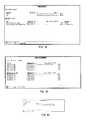
- Tag unit 18is a laptop wireless card with MAC address 00:20:A6:57:FC:F6.
- the total count of positioning readingsis between 20-500 in a preferred embodiment.
- the distribution of the top three locations vs. the countis illustrated in the table in FIG. 19 .
- the total count of positioning readingsis 1000.
- FIG. 20the legend for the office map is illustrated.
- the coordinates for the top three calibrated locations, WebEx office, Manager's office, and Office 1are illustrated in FIG. 21 .
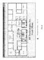
- the testwas run in Office 2 as illustrated on the map of the front offices, FIG. 21 . Inputting the data into equation (11):
- the calculated mean, or “near by” or “between” locationhas a coordinate of (7.0, 2.7) and is plotted on a map.
- tag unit 18is the same laptop wireless card with the same MAC address as in the above example. This time the total count is 500. The distribution of the location vs. count is listed in the table in FIG. 22 . In this example, the laptop is sitting in a location where there is no calibration data for that particular spot. The top three locations are then provided in a “near by” range. The actual location of tag unit 18 is in the triangular area created by the three locations. As illustrated in FIG. 23 , the top three locations calculated are: Manager's Office, Conference Room, and Office 1 . Inputting this data into equation (11):
- the calculated mean, or “near by” or “between” locationhas the coordinates (4.8,2.1) and is plotted on the map in FIG. 24 .
- a mobile resource manager software suitecan be used to enable users of asset tracking system 10 to configure and manage assets and track their equipment from any Internet enabled PC or PDA 13 .
- the mobile resource manager software suiteis a group of client applications, administrative tools, and custom MS Windows® services.
- the softwareprovides an efficient system for locating assets and analysis of asset utilization based on real-time location.
- information center 40which provides a single user interface to find resources, view alerts, run reports, create utilization charts, view floor plans, and monitor real-time data pertaining to location and alert states
- administrator center 41which provides a set of utilities that allow users to enroll and configure tag units 18 , and to enter resources, locations, alerts, triggers, and e-mail notifications
- search enginewhich is a browser-based application that can retrieve a list or map showing resource locations
- mobile view applicationwhich is a simplified interface designed for web-enabled devices, such as PDA's 13 (illustrated in FIG. 25 ), smart phones, cell phones, etc.
- FIG. 26is a screen shot of information center 40 , or a graphical user interface for asset tracing system 10 .
- Information center 40provides a single user interface to services and features available in a resource management software suite of asset tracking system 10 .
- Information center 40can be used locate resources, view alerts, run reports, create utilization charts, view floor plans and monitor real-time data pertaining to location and alert states.
- Information center 40is designed to allow the maximum amount of flexibility in arranging the layout of information. Logical groupings of information are created into windows which can be easily moved about the display screen, hidden from sight, or docked together in various arrangements.
- the select items window 42provides the user with a list of all of the resources, locations, location alerts, and reports, that exist for the facility.
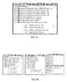
- the hierarchy selection tree structure 44allows users to select the information they want to include when generating reports. Selection tree 44 also provides the source of items for dragging and dropping items into each of the watch windows.
- Information center 40also displays information graphically through the use of charts and floor plans. Historical data can be retrieved from the database and displayed as utilization charts, which is a set of horizontal bar charts. Utilization is determined by the length of time a resource spends in a particular location.
- Floor plan area 46displays a graphical view of the facility. Predefined coordinates are used to dynamically place tag units 18 , on floor plan area in proper locations. This provides a graphical means of determining the locations of both resources and alerts.
- Resources to be trackedare assigned an icon during tag unit 18 configuration. The icon can be used to quickly identify a resource of a certain type.
- Tag unit 18can be assigned groupings such as grouping resources by department. Groups are provided with different background colors on the floor plan allowing individuals to quickly identify their resources.
- Watch window 48allows the viewing dynamic information. As tag unit 18 moves between locations, watch window 48 receives dynamic update messages, allowing them to display real-time alert and location information.
- the watch alerts window 50also provides audio notifications when an alert occurs. Alerts, resources, and locations can be selected in the select items tree and dropped into their respective watch windows to monitor real-time data events as they occur.
- alert watch window 48When an alert occurs that has dropped into alert watch window 48 , an audible alarm sounds at the monitoring end user device.
- Information center 40does not modify any of the data used, such as tags, locations, and alerts.
- Tag unit 18 locations and alertsare created in administration center 41 and dropped into respective watch windows 48 to monitor real-time data events as they occur.
- a rules tab 52is used to connect information center 40 to all of the available services and to retrieve the correct location and alerts from the database.
- information center 40refreshes with location and alerts from the selected rule set.
- Real-time data from positioning service 39such as alerts and positioning information rely upon the rule set to initialize a subscription to the service. New subscriptions are created when the rule set is changed.
- watch alerts window 50is designed to play pre-recorded audio alert messages when alerts occur in the system. This audio notification can be enabled or disabled through the options dialog.
- select items window 42allows users to check the items they want to include in their reports. Items defined within the facility are displayed to the user in hierarchical tree structure. Items include resources, locations, location alerts, and reports. The user is able to check the items they would like to include in their report. The user may also opt to drag these items into their watch windows 48 as a selection means also.
- the background color of the tree controlcan change to light green, as illustrated in FIG. 33 , when information center 40 receives an update message from administration center 41 .
- Update messagesinform information center 40 that tag unit 18 location or alert information has changed in the system.
- the usershould update information by hitting the refresh button on a browser. Once the refresh button is hit, the background color of the tree resets to white, as illustrated in FIG. 34 .
- a properties windowdisplays extended property information for any item selected in the tree view in regards to resource, location, location alert, or report, as illustrated in FIG. 35 .
- tag group properties window 54a color of the tag group is illustrated. Color is used as background color for icons when displayed on a floor plan map. A group name for tag unit 18 is also indicated.
- location properties window 56location ID, location name, path of location, rules, etc. may be listed.
- location alert properties window 58an indication of: alert type, alert id, alert description, location of alert, resource of alert, and audible signal information is given.
- Report properties window 60allows user 11 to view a report id, report name, category of report, owner of report, and user level of report. Additional information can include, creation date of report, last modification date of report, and a report value.
- a report windowis populated anytime user 11 performs a search by hitting a locate button in a select items window.
- a report windowdisplays search results as text in table format as illustrated in FIG. 36 .
- the following featurescan be built into the display: columns for display can be selected based on report type; sort orders can be based on the report type; the column widths can be auto-sized based on information appearing in a list view; clicking on a column header can sort the information based on that column; rows can be auto-shaded to help visually separate items from one another; and an icon can be assigned to each item appearing in a list.
- a chart windowcan be populated anytime user 11 performs a search by hitting a locate button in a select items window, as illustrated in FIG. 37 .
- Chart windowscan display search results in a horizontal bar chart format.
- the following itemscan be built into the bar chart display: group bar charts can be formatted blue; individual bar charts can be formatted in green; bar values can be drawn normalized ensuring at least one bar is always drawn to its maximum; bar percentages can be based off of a maximum bar chart value, or a sum of bar chart values.
- Sample chartsare illustrated in FIGS. 39 and 40 .
- a floor plan windowvisually displays resources or alerts hovering over a floor plan image.
- User 11can select any one floor plan at a time and a data source from which to plot the items. Items that are not located on a selected floor plan are filtered out of the display.
- a floor plan windowis only available if floor plans rules were created for the facility.
- Floor plan imagescan be retrieved from a database when an application is initialized.
- a location builder tool in administration center 41can be used to place locations on a floor plan.
- a floor plan ruleis set as a mapping of locations to coordinates on a floor plan image. Each time information center 40 is started or a refresh button is hit, floor plan rule sets are loaded.
- Iconscan be assigned to resources through administration center 41 to each resource being tracked. Icons can be displayed on a floor plan as a 32 pixel icon when it first appears and as a 16 pixel icon after the initial location change event has occurred. Whenever a resource changes location, an icon is displayed at a larger size and flashes, alerting user 11 to a location change.
- a background color of the iconis based on a tag group which tag unit 18 is located. This allows user 11 to instantly recognize foreign resources in a department or to find department assets in other locations.
- Tag group background colorscan be assigned through administration center 41 .
- display examplesare illustrated both as icons and text based locations.
- Watch alerts window 50can have the following features: watch alerts background formatted light red; only alerts “in progress” appear in watch alerts window 50 ; alerts can be automatically sorted by time ensuring that the most recent alerts appear at the top of a list; a right click of a mouse brings up watch manager and user 11 can view a list of all of alerts being watched; an alert can only be removed from a list by deleting a watch from a watch manager, or by clearing the offending alert in the system.
- Watch alert window 50can be the only watch window having audio support. Audio notifications can be pre-recorded WAV (Waveform audio format) files named after a corresponding alert type. User 11 can replace the WAV files with their own, provided that file names are not changed. When several alerts are triggered at once, audio notifications can be queued and played one after an other. A table of alert icons is illustrated in FIG. 44 .
- WAVWideform audio format
- Watch resources windowcan have the following features: watch resources background can be formatted light blue; only resources that can be located by the system appear in watch resources window; resources can be automatically sorted by ‘group’; a right click on a mouse brings up watch manager and user 11 may view a list of all resources being monitored; and a resource can only be removed from the list by deleting a watch from watch manager.
- locationscan be dragged from a selection tree and dropped into a watch locations window, as illustrated in FIG. 46 .
- Watch locations windowcan have the following features: watch locations background can be formatted light yellow; only resources can be located by asset tracking system 10 and fall into one of the watched locations appearing in a watch locations window; resources can be automatically sorted by ‘group’; a right click of a mouse button can bring up a watch manager and user 11 may view all of the locations being watched; and a resource can only be removed form the list by deleting a location it resides in from watch manager
- watch managercan be used to view and delete items being watched in any of the given watch windows as illustrated in FIG. 47 .
- Watch managercan have the following features: the background color of watch manager can match the watch window that invoked it.
- Watch manager popup menucan allow user 11 to toggle individual alert audio on or off, delete selected watches, and delete all watches. Watch window examples are illustrated if FIG. 48 .
- tag unit 18 locationscan be assigned a “location type” to monitor and analyze workflow in a facility.
- Each room in a facilitycan be designated to a particular category (i.e. storage, cleaning, closet, etc.).
- Tag units 18can be tracked by a time increment that tag unit 18 resides in each category.
- a graphical analysisi.e. pie chart, bar graph, line graph, pictorial, etc.
- a graphical analysiscan be created to allow user 11 to analyze utilization of a facility's asset(s).
- a resource profilecan be assigned to an asset during an initial set-up of an asset in a database.
- Facility assetsmay vary in regards to mobility, usage, time of usage, alarms, etc.
- Profilescan be created to attach to tag unit 18 . These profiles can be saved in a database.
- a profilecan be an identifying number, text string, icon, etc. and can be configured by users of the asset tracking system 10 .
- Information contained in a profilecan be any the following or combination thereof: a tamper detect enable, tamper alert early, tamper test interval, tamper test count, a motion detect enable, a static proximity announce interval, etc.
- Profile information for each tag unit 18can be stored in a database for use on an as needed basis.
- tag unit 18can be battery powered. Embedded in tag unit 18 can be software iterations that provide power saving modes within tag unit 18 to extend the life of the battery. Access points 16 may emit different transmissions that allow tag unit 18 to use less power with some transmissions than other transmissions.
- color coding of assetscan be used by assigning a specific color to the following areas of the facility: floors, departments, wings, zones, rooms, etc of a facility.
- a colorcan be designated such that the assets assigned to the floor, department, wing, zone, room, etc. or any combination thereof are tracked, managed, and accounted for accordingly
- Tag units 18can be programmed with a variety of information upon initial set up.
- tag unit 18is placed on an asset.
- tag unit 18can begin transmitting a station set identifier.
- the administration centerpinpoint alarm center then auto enrolls tag unit 18 in the database by picking up a transmission.
- the usercan be alerted that a new asset has been tagged. This alert may be presented on PDA 13 , laptop 15 , or other user end device.
- User 11can choose to enter a name, a serial number, or some other identifier of the asset, and the asset can be automatically enrolled in the database.
- a listmay be derived of preventative maintenance tasks for various assets.
- the listcan be associated with specific assets and their locations.
- the listcan be generated by equipment type, location within the facility, technology, etc.
- the preventative maintenancecan be performed as user 11 proceeds through a building by floor, zone, area, type of equipment, etc.
- a virtual LANcan be used for asset tracking system 10 . This can allow the facility to separate their asset tracking system traffic from the rest of their network.
- tag units 18may be assigned an ID and calibrated using PDA 13 or laptop 15 . The number of samples and the time frame they are taken can be tracked and analyzed over time.
- positioning service 14can be utilized to manage information regarding the assets.
- Positioning service 15can perform the following or any combination thereof; receive calibration rules from an application, listen for tag unit 18 messages, determine if a tag packet is for calibration by matching it to the calibration rules, publish changes in tag unit 18 status to subscribers, etc. All information discussed in this application can be managed by positioning service 14 .
- reference tagscan be used to account for drift over time. As samples are taken for analysis and/or calibration of tag unit 18 , over time, the data may shift or vary. The data collection may not have a specific start and stop time. Rather, the sample is taken over time and the drift becomes a “moving average” of the tracked data. In one embodiment, a real time calibration can be performed in response to drifts.
- a notificationmay be given to user 11 that there may not be enough assets available at a particular location in the facility.
- the locationcan be a room, zone, wing, floor, etc.
- a predetermined number of assetscan be programmed into a database by user 11 .
- User 11can set an asset requirement for specific areas of the facility. Should the number of assets drop below the requirement, user 11 may then be alerted by asset tracking system 10 that asset resources are low. User 11 can then respond by replacing the depleted supply of assets.
- a facilitymay choose to monitor whether or not assets are being placed in proper locations and how often assets are located in incorrect locations.
- Software employed on station 12can track asset locations and compare to desired locations for the assets. A report indicating the percentage of time certain assets are located in a proper place can be generated.
- tag unit 18contains a motion detector. If tag unit 18 move from one location to another, a motion flag may be transmitted to a user interface or to station 12 . Once a motion flag is transmitted, movement is noted within a database (preferably stored in station 12 ). The movement is then recorded in a database. If a motion flag is not sent by tag unit 18 and yet station 12 otherwise determines (e.g. by tracking location of the asset), tag unit 18 is flagged by station 12 as emitting inaccurate information. The correct and incorrect information can be recorded in a database. The information can be tracked and utilized for an analysis of system accuracy. An analysis can be made available to user 11 and can be displayed graphically in the form of a pie chart, bar graph, line graph, text, etc.
- the present inventioncontemplates methods, systems and program products on any machine-readable media for accomplishing its operations.
- the embodiments of the present inventionmay be implemented using an existing computer processors, or by a special purpose computer processor for an appropriate electronic medical records system, incorporated for this or another purpose or by a hardwired system.
- Embodiments within the scope of the present inventionmay include program products comprising machine-readable media for carrying or having machine-executable instructions or data structures stored thereon.
- machine-readable mediacan be any available media which can be accessed by a general purpose or special purpose computer or other machine with a processor.
- machine-readable mediacan comprise RAM, ROM, EPROM, EEPROM, CD-ROM or other optical disk storage, magnetic disk storage or other magnetic storage devices, or any other medium which can be used to carry or store desired program code in the form of machine-executable instructions or data structures and which can be accessed by a general purpose or special purpose computer or other machine with a processor. Combinations of the above are also included within the scope of machine-readable media.
- Machine-executable instructionscomprise, for example, instructions and data which cause a general purpose computer, special purpose computer, or special purpose processing machines to perform a certain function or group of functions.
- Software implementations of the present inventioncould be accomplished with standard programming techniques with rule based logic and other logic to accomplish the various connection steps, processing steps, comparison steps and decision steps. Attachment A to the provisional application includes further descriptions and details related to exemplary asset tracking systems.
Landscapes
- Engineering & Computer Science (AREA)
- Business, Economics & Management (AREA)
- Strategic Management (AREA)
- General Physics & Mathematics (AREA)
- Economics (AREA)
- Entrepreneurship & Innovation (AREA)
- Physics & Mathematics (AREA)
- Human Resources & Organizations (AREA)
- Educational Administration (AREA)
- Marketing (AREA)
- Operations Research (AREA)
- Quality & Reliability (AREA)
- Tourism & Hospitality (AREA)
- Game Theory and Decision Science (AREA)
- General Business, Economics & Management (AREA)
- Development Economics (AREA)
- Theoretical Computer Science (AREA)
- Position Fixing By Use Of Radio Waves (AREA)
- Mobile Radio Communication Systems (AREA)
Abstract
Description
Hjk, j=1, . . . , J, k=1, . . . K
will provide a J×K matrix, or a J×K dimensional vector space.
The definition of normalized histogram is:
Therefore:
P(50)=0.8, P(55)=0.05, andP(60)=0.065
The calibration normalized histogram is a set of probabilities:
Hjk={Pi(RSSI)|i=min, . . . , max}
If a testing sample contains:
{60,55,50,50,50},
then the test vector components become:
V(50)=3, V(55)=1, V(60)=1,
then the inter product of these two vectors is:
P(50)·V(50)+P(55)·V(55)+P(60)·P(60)=2.4+0.05+0.065=2.515.
After finding inter products with all location calibration vectors, the top two locations with the highest inter product values are the output of the vector algorithm. In an exemplary embodiment, the first step in the analysis is to define RSSI. The RSSI is related to the value of the amount of energy present in the dBm (dB milliwatts) scale. The mathematical definition of RSSI:
RSSI(x) is the value measured by
The amount of energy is proportional to the reciprocal of x2, and I(0) is a constant of AP16:
RSSI(x)=−20 log10x−A (3)
Then, the derivative of RSSI(x) as illustrated in
Therefore,
Consider the most simple case (see
If ΔRSSI(x)=−5, and x2−x1=Δx=3, then the estimated distance between
where,
EffectiveAreaOfAP=π×(EffectiveRadiusOfAP)2. (9)
Therefore, a GPS, in free space, can determine a target position of
The calculated mean, or “near by” or “between” location has a coordinate of (7.0, 2.7) and is plotted on a map.
The calculated mean, or “near by” or “between” location has the coordinates (4.8,2.1) and is plotted on the map in
Claims (20)
Priority Applications (3)
| Application Number | Priority Date | Filing Date | Title |
|---|---|---|---|
| US12/036,136US8026814B1 (en) | 2007-07-25 | 2008-02-22 | Wireless mesh network for an asset tracking system |
| US12/347,785US8400268B1 (en) | 2007-07-25 | 2008-12-31 | End to end emergency response |
| US13/763,316US8674806B1 (en) | 2007-07-25 | 2013-02-08 | End to end emergency response |
Applications Claiming Priority (2)
| Application Number | Priority Date | Filing Date | Title |
|---|---|---|---|
| US96189407P | 2007-07-25 | 2007-07-25 | |
| US12/036,136US8026814B1 (en) | 2007-07-25 | 2008-02-22 | Wireless mesh network for an asset tracking system |
Related Parent Applications (1)
| Application Number | Title | Priority Date | Filing Date |
|---|---|---|---|
| US12/178,480Continuation-In-PartUS8373562B1 (en) | 2007-07-25 | 2008-07-23 | Asset tracking system |
Related Child Applications (1)
| Application Number | Title | Priority Date | Filing Date |
|---|---|---|---|
| US12/347,785Continuation-In-PartUS8400268B1 (en) | 2007-07-25 | 2008-12-31 | End to end emergency response |
Publications (1)
| Publication Number | Publication Date |
|---|---|
| US8026814B1true US8026814B1 (en) | 2011-09-27 |
Family
ID=44652507
Family Applications (2)
| Application Number | Title | Priority Date | Filing Date |
|---|---|---|---|
| US12/036,136Active2030-03-26US8026814B1 (en) | 2007-07-25 | 2008-02-22 | Wireless mesh network for an asset tracking system |
| US12/178,480Active2030-10-02US8373562B1 (en) | 2007-07-25 | 2008-07-23 | Asset tracking system |
Family Applications After (1)
| Application Number | Title | Priority Date | Filing Date |
|---|---|---|---|
| US12/178,480Active2030-10-02US8373562B1 (en) | 2007-07-25 | 2008-07-23 | Asset tracking system |
Country Status (1)
| Country | Link |
|---|---|
| US (2) | US8026814B1 (en) |
Cited By (71)
| Publication number | Priority date | Publication date | Assignee | Title |
|---|---|---|---|---|
| US20090219170A1 (en)* | 2008-02-18 | 2009-09-03 | Clark Ryan C | Wireless network inventory system |
| US20100060452A1 (en)* | 2008-09-05 | 2010-03-11 | DearlerMesh, Inc. | Using a mesh of radio frequency identification tags for tracking entities at a site |
| US20110068921A1 (en)* | 2009-09-21 | 2011-03-24 | Checkpoint Systems, Inc. | configurable monitoring device |
| US20120309422A1 (en)* | 2010-02-19 | 2012-12-06 | Jonathan Philip Lewis-Evans | System and method for locating physical assets |
| WO2013063121A1 (en)* | 2011-10-24 | 2013-05-02 | Qualcomm Incorporated | Methods and devices for serving as a proxy beacon for a tracking device |
| US8452868B2 (en) | 2009-09-21 | 2013-05-28 | Checkpoint Systems, Inc. | Retail product tracking system, method, and apparatus |
| WO2013057578A3 (en)* | 2011-10-16 | 2013-06-06 | Mashinery Pty Ltd. | Object location and tracking |
| US8463888B1 (en)* | 2010-12-06 | 2013-06-11 | The Boeing Company | Methods and systems for managing automated identification technologies information |
| US20130159351A1 (en)* | 2011-12-14 | 2013-06-20 | International Business Machines Corporation | Asset Identity Resolution Via Automatic Model Mapping Between Systems With Spatial Data |
| US20150002274A1 (en)* | 2013-06-26 | 2015-01-01 | Trackblue, Llc | Asset Tag Apparatus and Related Methods |
| WO2015066364A1 (en)* | 2013-11-01 | 2015-05-07 | Trimble Navigation Limited | Long-life asset tracking |
| US20150195322A1 (en)* | 2012-09-20 | 2015-07-09 | Huawei Device Co., Ltd. | Media Resource Playback Method and System |
| WO2015164838A1 (en)* | 2014-04-25 | 2015-10-29 | Aktiebolaget Skf | Method of operating a system for precisely locating an asset point in a physical plant |
| WO2015164837A1 (en)* | 2014-04-25 | 2015-10-29 | Aktiebolaget Skf | System for precisely locating an asset point in a physical plant |
| US20160050519A1 (en)* | 2014-08-14 | 2016-02-18 | Nicholas Sandin | Embedded location tracking systems for sports equipment |
| US20160063828A1 (en)* | 2014-09-02 | 2016-03-03 | Apple Inc. | Semantic Framework for Variable Haptic Output |
| US20160173482A1 (en)* | 2013-07-05 | 2016-06-16 | Zte Corporation | Cu login method and system |
| US9467862B2 (en) | 2011-10-26 | 2016-10-11 | Milwaukee Electric Tool Corporation | Wireless tracking of power tools and related devices |
| US9466198B2 (en) | 2013-02-22 | 2016-10-11 | Milwaukee Electric Tool Corporation | Wireless tracking of power tools and related devices |
| US20160302035A1 (en)* | 2015-04-08 | 2016-10-13 | Abb Technology Ag | Location estimation within a wireless mesh network utilizing wireless signal signatures |
| US20160381582A1 (en)* | 2015-06-24 | 2016-12-29 | International Business Machines Corporation | Beacon array |
| US20170064507A1 (en)* | 2015-08-27 | 2017-03-02 | GeoShephard, Inc. | Plant diagnostic and location detection means and system |
| US9635545B2 (en) | 2010-07-21 | 2017-04-25 | Sensoriant, Inc. | System and method for controlling mobile services using sensor information |
| US20170124827A1 (en)* | 2015-10-31 | 2017-05-04 | Aprium Tech Limited | Identifying an Association between a User of a Mobile Device and an Item of Merchandise |
| US9652955B1 (en)* | 2016-06-21 | 2017-05-16 | Link Labs, Inc. | Real-time asset location system and method with long-range wireless backhaul |
| US20170154508A1 (en)* | 2015-05-05 | 2017-06-01 | Invue Security Products Inc. | Wireless beacon tracking system for merchandise security |
| US9681254B2 (en) | 2010-07-21 | 2017-06-13 | Sensoriant, Inc. | System and method for control and management of resources for consumers of information |
| US9715707B2 (en) | 2010-07-21 | 2017-07-25 | Sensoriant, Inc. | System and method for control and management of resources for consumers of information |
| WO2018005684A1 (en)* | 2016-06-28 | 2018-01-04 | SekureTrak, Inc. | Systems and methods for tracking items |
| US9864432B1 (en) | 2016-09-06 | 2018-01-09 | Apple Inc. | Devices, methods, and graphical user interfaces for haptic mixing |
| US9904885B2 (en) | 2014-04-06 | 2018-02-27 | Vypin, LLC | Wireless medication compliance sensing device, system, and related methods |
| US9911296B2 (en) | 2014-12-10 | 2018-03-06 | Gogoro Inc. | Systems and methods for asset tracking using an ad-hoc mesh network of mobile devices |
| US9980092B1 (en) | 2017-01-31 | 2018-05-22 | Here Global B.V. | Supporting a surveillance of positions of devices |
| US9984539B2 (en) | 2016-06-12 | 2018-05-29 | Apple Inc. | Devices, methods, and graphical user interfaces for providing haptic feedback |
| US9996157B2 (en) | 2016-06-12 | 2018-06-12 | Apple Inc. | Devices, methods, and graphical user interfaces for providing haptic feedback |
| US20180268346A1 (en)* | 2017-03-20 | 2018-09-20 | Panasonic Intellectual Property Management Co., Ltd. | Method and system for tracking and managing locations of workers in a park |
| US10131043B2 (en) | 2013-10-21 | 2018-11-20 | Milwaukee Electric Tool Corporation | Adapter for power tool devices |
| US10158213B2 (en) | 2013-02-22 | 2018-12-18 | Milwaukee Electric Tool Corporation | Worksite power distribution box |
| US10175762B2 (en) | 2016-09-06 | 2019-01-08 | Apple Inc. | Devices, methods, and graphical user interfaces for generating tactile outputs |
| US10210353B1 (en) | 2018-03-09 | 2019-02-19 | Abl Ip Holding Llc | Asset tag tracking system and network architecture |
| US10237913B2 (en) | 2017-06-17 | 2019-03-19 | Link Labs, Inc. | BLE networking systems and methods providing central and peripheral role reversal thereof while movable between locations |
| US10244373B2 (en) | 2017-06-17 | 2019-03-26 | Link Labs, Inc. | BLE networking systems and methods providing central and peripheral role reversal |
| US10244377B2 (en) | 2017-06-17 | 2019-03-26 | Link Labs, Inc. | BLE networking systems and methods providing central and peripheral role reversal according to network provisioned timing therefor |
| US10264436B1 (en) | 2018-05-29 | 2019-04-16 | Link Labs, Inc. | BLE networking systems and methods providing central and peripheral role reversal with independent peripheral network connectivity |
| US10346649B2 (en) | 2017-01-11 | 2019-07-09 | Abl Ip Holding Llc | Asset tracking using active wireless tags that report via a local network of connected beacons |
| US10390289B2 (en) | 2014-07-11 | 2019-08-20 | Sensoriant, Inc. | Systems and methods for mediating representations allowing control of devices located in an environment having broadcasting devices |
| US10422848B1 (en) | 2018-03-09 | 2019-09-24 | Abl Ip Holding Llc | More accurate asset tag locating of radio frequency devices |
| US10438476B2 (en) | 2013-06-26 | 2019-10-08 | Vypin, LLC | Wireless hand hygiene tracking system and related techniques |
| US10484932B2 (en) | 2017-06-17 | 2019-11-19 | Link Labs, Inc. | BLE networking systems and methods providing central and peripheral role reversal with enhanced peripheral location determination using ultrasonic waveform |
| US20190354921A1 (en)* | 2018-05-17 | 2019-11-21 | HERE Global, B.V. | Venue map based security infrastructure management |
| US10499196B2 (en) | 2017-06-17 | 2019-12-03 | Link Labs, Inc. | BLE networking systems and methods providing central and peripheral role reversal with enhanced peripheral location determination |
| US10506498B1 (en) | 2018-11-01 | 2019-12-10 | Link Labs, Inc. | BLE networking systems and methods providing central and peripheral role reversal with enhanced peripheral location determination using ultrasonic waveform and correlation therefor |
| US10502811B2 (en) | 2018-03-09 | 2019-12-10 | Abl Ip Holding Llc | Network architecture, radio frequency based asset tracking and/or location estimation methods and systems |
| US10572700B2 (en) | 2013-06-26 | 2020-02-25 | Vypin, LLC | Wireless asset location tracking system and related techniques |
| US10614473B2 (en) | 2014-07-11 | 2020-04-07 | Sensoriant, Inc. | System and method for mediating representations with respect to user preferences |
| US20200150264A1 (en)* | 2018-11-14 | 2020-05-14 | Honeywell International Inc. | Systems and methods for security system device tamper detection |
| US10708970B2 (en) | 2017-06-17 | 2020-07-07 | Link Labs, Inc. | BLE networking systems and methods providing central and peripheral role reversal with enhanced peripheral location determination using constant tone extension analysis for a same channel |
| US20200349665A1 (en)* | 2019-05-03 | 2020-11-05 | United States Postal Service | Informed mobility platform for an item processing supervisor or user within a distribution facility |
| US10827735B2 (en) | 2015-09-19 | 2020-11-10 | Vulture Systems, LLC | Remotely detectable transportable game and fishing alarm system |
| WO2021050211A1 (en)* | 2019-09-13 | 2021-03-18 | Troverlo, Llc | Passive asset tracking with existing infrastructure |
| US11102617B2 (en) | 2020-01-15 | 2021-08-24 | Stmicroelectronics International N.V. | Indoor navigation and tracking with mesh network |
| US11275149B2 (en)* | 2016-03-18 | 2022-03-15 | Embarcadero Technologies, Inc. | Determining a location of an electronic device |
| US11308950B2 (en) | 2018-05-09 | 2022-04-19 | 4PLAN Corporation | Personal location system for virtual assistant |
| US11314330B2 (en) | 2017-05-16 | 2022-04-26 | Apple Inc. | Tactile feedback for locked device user interfaces |
| US11336505B2 (en)* | 2016-06-10 | 2022-05-17 | Vmware, Inc. | Persistent alert notes |
| CN114915904A (en)* | 2022-05-05 | 2022-08-16 | 广州云新信息技术有限公司 | Asset positioning method and device |
| US11778540B1 (en) | 2022-10-12 | 2023-10-03 | Link Labs, Inc. | BLE networking systems and methods including filtering for selectively collecting and processing advertisement data |
| US20230401643A1 (en)* | 2022-06-10 | 2023-12-14 | Honeywell International Inc. | Systems and Methods for Global Operations Display |
| US11991638B2 (en) | 2019-04-30 | 2024-05-21 | Hewlett-Packard Development Company, L.P. | Managing aggregated node group power states |
| US20250094916A1 (en)* | 2019-10-23 | 2025-03-20 | Moeco IoT Inc. | System including a server system, a plurality of gateways and a device |
| US12436778B2 (en) | 2014-08-22 | 2025-10-07 | Sensoriant, Inc. | Deriving personalized experiences of smart environments |
Families Citing this family (33)
| Publication number | Priority date | Publication date | Assignee | Title |
|---|---|---|---|---|
| WO2005086802A2 (en) | 2004-03-08 | 2005-09-22 | Proxense, Llc | Linked account system using personal digital key (pdk-las) |
| EP1829283A2 (en) | 2004-12-20 | 2007-09-05 | Proxense, LLC | Biometric personal data key (pdk) authentication |
| US11206664B2 (en) | 2006-01-06 | 2021-12-21 | Proxense, Llc | Wireless network synchronization of cells and client devices on a network |
| US8219129B2 (en) | 2006-01-06 | 2012-07-10 | Proxense, Llc | Dynamic real-time tiered client access |
| US7904718B2 (en) | 2006-05-05 | 2011-03-08 | Proxense, Llc | Personal digital key differentiation for secure transactions |
| US9269221B2 (en) | 2006-11-13 | 2016-02-23 | John J. Gobbi | Configuration of interfaces for a location detection system and application |
| US8659427B2 (en) | 2007-11-09 | 2014-02-25 | Proxense, Llc | Proximity-sensor supporting multiple application services |
| US8171528B1 (en) | 2007-12-06 | 2012-05-01 | Proxense, Llc | Hybrid device having a personal digital key and receiver-decoder circuit and methods of use |
| US9251332B2 (en) | 2007-12-19 | 2016-02-02 | Proxense, Llc | Security system and method for controlling access to computing resources |
| WO2009102979A2 (en) | 2008-02-14 | 2009-08-20 | Proxense, Llc | Proximity-based healthcare management system with automatic access to private information |
| WO2009126732A2 (en) | 2008-04-08 | 2009-10-15 | Proxense, Llc | Automated service-based order processing |
| CN101556710B (en)* | 2009-01-22 | 2010-12-01 | 上海国际港务(集团)股份有限公司 | Container global tracking management method and electronic device and read-write device for implementing the method |
| US8633817B2 (en)* | 2009-10-21 | 2014-01-21 | Qualcomm Incorporated | Mapping wireless signals with motion sensors |
| US9418205B2 (en) | 2010-03-15 | 2016-08-16 | Proxense, Llc | Proximity-based system for automatic application or data access and item tracking |
| US8918854B1 (en) | 2010-07-15 | 2014-12-23 | Proxense, Llc | Proximity-based system for automatic application initialization |
| US8857716B1 (en) | 2011-02-21 | 2014-10-14 | Proxense, Llc | Implementation of a proximity-based system for object tracking and automatic application initialization |
| WO2014163948A1 (en)* | 2013-03-13 | 2014-10-09 | Awarepoint Corporation | Workflow context aware location tracking system and method |
| WO2014183106A2 (en) | 2013-05-10 | 2014-11-13 | Proxense, Llc | Secure element as a digital pocket |
| US9225858B2 (en) | 2013-09-30 | 2015-12-29 | Lexmark International, Inc. | Systems and methods for location-aware imaging devices |
| EP3361428A1 (en)* | 2017-02-10 | 2018-08-15 | Fujitsu Limited | Asset location identification system, program and method |
| US10341814B2 (en) | 2017-03-17 | 2019-07-02 | SCRRD, Inc. | Wireless device detection, tracking, and authentication platform and techniques |
| US10085118B1 (en) | 2017-03-17 | 2018-09-25 | SCRRD, Inc. | Wireless device detection, tracking, and authentication platform and techniques |
| CA3056593A1 (en) | 2017-03-17 | 2018-09-20 | SCRRD, Inc. | Wireless device detection, tracking, and authentication platform and techniques |
| EP4404641A3 (en) | 2017-11-30 | 2024-10-09 | Samsung Electronics Co., Ltd. | Apparatus and method for searching and registering tags in local positioning system |
| US10783420B2 (en) | 2018-11-07 | 2020-09-22 | Adero, Inc. | Tag for wirelessly organizing a physical object |
| US10945092B2 (en)* | 2018-11-07 | 2021-03-09 | Adero, Inc. | Organizing physical objects using wireless tags |
| US10911899B2 (en)* | 2018-11-07 | 2021-02-02 | Adero, Inc. | Providing indication to location of physical object using wireless tag |
| BR112021023442A2 (en)* | 2019-05-22 | 2022-01-11 | Bayer Ag | product tracking |
| US12256294B2 (en) | 2019-07-19 | 2025-03-18 | Blind InSites, LLC | Systems and methods for wireless physical condition instruction generation |
| US10956690B1 (en) | 2019-09-25 | 2021-03-23 | International Business Machines Corporation | Set-based object management system |
| WO2021062351A1 (en)* | 2019-09-27 | 2021-04-01 | Fire Research Corp. | Asset tracking system |
| CN116520239A (en)* | 2022-01-31 | 2023-08-01 | 希尔-罗姆服务公司 | Medical institution positioning system label |
| US12217866B2 (en) | 2022-01-31 | 2025-02-04 | Hill-Rom Services, Inc. | Tags for locating system of medical facility |
Citations (8)
| Publication number | Priority date | Publication date | Assignee | Title |
|---|---|---|---|---|
| US5793290A (en) | 1996-02-29 | 1998-08-11 | Rf Technologies, Inc. | Area security system |
| US20040169587A1 (en)* | 2003-01-02 | 2004-09-02 | Washington Richard G. | Systems and methods for location of objects |
| US20060125631A1 (en)* | 2002-08-08 | 2006-06-15 | Jacob Sharony | RF tracking system and method |
| US7098792B1 (en) | 2003-05-14 | 2006-08-29 | Rf Technologies, Inc. | Tamper proof system and method |
| US7180420B2 (en)* | 2004-05-25 | 2007-02-20 | Mgm Computer Systems, Inc. | System and method using triangulation with RF/LF and infrared devices for tracking objects |
| US7274294B2 (en) | 2005-01-26 | 2007-09-25 | Rf Technologies, Inc. | Mobile locator system and method |
| US20070247286A1 (en)* | 2006-03-31 | 2007-10-25 | Symbol Technologies, Inc. | RFID tag receive signal strength indicator |
| US7365645B2 (en) | 2005-01-26 | 2008-04-29 | Rf Technologies, Inc. | Mobile locator system and method with wander management |
Family Cites Families (30)
| Publication number | Priority date | Publication date | Assignee | Title |
|---|---|---|---|---|
| US5387993A (en) | 1993-06-25 | 1995-02-07 | Precision Tracking Fm, Inc. | Method for receiving and transmitting optical data and control information to and from remotely located receivers and transmitters in an optical locator system |
| US5485163A (en) | 1994-03-30 | 1996-01-16 | Motorola, Inc. | Personal locator system |
| US5602744A (en) | 1994-09-29 | 1997-02-11 | Meek; Jean L. | Universal send/receive utility usage data gathering system |
| US7088233B2 (en) | 1998-10-23 | 2006-08-08 | Royal Thoughts, Llc | Personal medical device communication system and method |
| US6396413B2 (en) | 1999-03-11 | 2002-05-28 | Telephonics Corporation | Personal alarm monitor system |
| US6661335B1 (en) | 1999-09-24 | 2003-12-09 | Ge Interlogix, Inc. | System and method for locating radio frequency identification tags |
| US7411921B2 (en) | 1999-10-21 | 2008-08-12 | Rf Technologies, Inc. | Method and apparatus for integrating wireless communication and asset location |
| US6893396B2 (en) | 2000-03-01 | 2005-05-17 | I-Medik, Inc. | Wireless internet bio-telemetry monitoring system and interface |
| US7038584B2 (en) | 2000-03-31 | 2006-05-02 | Ge Medical Systems Information Technologies, Inc. | Object location monitoring within buildings |
| US20020036569A1 (en) | 2000-08-14 | 2002-03-28 | Martin Philip John | Tag and receiver systems |
| WO2002103384A1 (en) | 2001-06-19 | 2002-12-27 | Star Bt Limited | Location, communication and tracking systems |
| US7310424B2 (en) | 2001-08-22 | 2007-12-18 | General Atomics | Encryption key distribution and network registration system, apparatus and method |
| US7993266B2 (en) | 2002-04-26 | 2011-08-09 | Lawrence Livermore National Security, Llc | Early detection of contagious diseases |
| US6639516B1 (en) | 2002-05-14 | 2003-10-28 | Shaun Michael Copley | Personal tracking device |
| US20030235172A1 (en)* | 2002-06-24 | 2003-12-25 | Intel Corporation | Asset tracking methods and apparatus |
| US7295115B2 (en)* | 2002-10-18 | 2007-11-13 | Aeroscout, Ltd. | Radio-frequency identification (RFID) tag employing unique reception window and method therefor |
| US7154398B2 (en) | 2003-01-06 | 2006-12-26 | Chen Thomas C H | Wireless communication and global location enabled intelligent health monitoring system |
| US6998985B2 (en) | 2003-03-05 | 2006-02-14 | Dmatek, Ltd. | Monitoring and tracking network |
| US7394385B2 (en) | 2003-07-31 | 2008-07-01 | Wellcare Systems, Inc. | Comprehensive monitoring system |
| WO2005062066A2 (en) | 2003-10-22 | 2005-07-07 | Awarepoint Corporation | Wireless position location and tracking system |
| US7155238B2 (en)* | 2004-07-06 | 2006-12-26 | Katz Daniel A | Wireless location determining device |
| US7174172B2 (en)* | 2005-02-25 | 2007-02-06 | Symbol Technologies, Inc. | System and method for asset location in wireless networks |
| US7323991B1 (en) | 2005-05-12 | 2008-01-29 | Exavera Technologies Incorporated | System and method for locating and communicating with personnel and equipment in a facility |
| US20070123597A1 (en) | 2005-11-29 | 2007-05-31 | Ford Global Technologies, Llc | Encapsulated flexible polyurethane foam and method for making polyol to form foam |
| US20070132576A1 (en) | 2005-12-08 | 2007-06-14 | Honeywell International Inc. | Method and apparatus for tracking persons |
| US20070132597A1 (en) | 2005-12-09 | 2007-06-14 | Valence Broadband, Inc. | Methods and systems for monitoring patient support exiting and initiating response |
| EP1968691A4 (en) | 2005-12-14 | 2012-01-25 | Welch Allyn Inc | WIRELESS ADAPTER FOR MEDICAL DEVICE |
| US7701332B2 (en) | 2005-12-30 | 2010-04-20 | Healthsense | Remote device for a monitoring system |
| US8164461B2 (en) | 2005-12-30 | 2012-04-24 | Healthsense, Inc. | Monitoring task performance |
| US7916023B2 (en)* | 2006-01-31 | 2011-03-29 | Zebra Enterprise Solutions Corp. | System and method for tracking assets within a monitored environment |
- 2008
- 2008-02-22USUS12/036,136patent/US8026814B1/enactiveActive
- 2008-07-23USUS12/178,480patent/US8373562B1/enactiveActive
Patent Citations (8)
| Publication number | Priority date | Publication date | Assignee | Title |
|---|---|---|---|---|
| US5793290A (en) | 1996-02-29 | 1998-08-11 | Rf Technologies, Inc. | Area security system |
| US20060125631A1 (en)* | 2002-08-08 | 2006-06-15 | Jacob Sharony | RF tracking system and method |
| US20040169587A1 (en)* | 2003-01-02 | 2004-09-02 | Washington Richard G. | Systems and methods for location of objects |
| US7098792B1 (en) | 2003-05-14 | 2006-08-29 | Rf Technologies, Inc. | Tamper proof system and method |
| US7180420B2 (en)* | 2004-05-25 | 2007-02-20 | Mgm Computer Systems, Inc. | System and method using triangulation with RF/LF and infrared devices for tracking objects |
| US7274294B2 (en) | 2005-01-26 | 2007-09-25 | Rf Technologies, Inc. | Mobile locator system and method |
| US7365645B2 (en) | 2005-01-26 | 2008-04-29 | Rf Technologies, Inc. | Mobile locator system and method with wander management |
| US20070247286A1 (en)* | 2006-03-31 | 2007-10-25 | Symbol Technologies, Inc. | RFID tag receive signal strength indicator |
Cited By (162)
| Publication number | Priority date | Publication date | Assignee | Title |
|---|---|---|---|---|
| US20090219170A1 (en)* | 2008-02-18 | 2009-09-03 | Clark Ryan C | Wireless network inventory system |
| US8471706B2 (en)* | 2008-09-05 | 2013-06-25 | John Schuster | Using a mesh of radio frequency identification tags for tracking entities at a site |
| US20100060452A1 (en)* | 2008-09-05 | 2010-03-11 | DearlerMesh, Inc. | Using a mesh of radio frequency identification tags for tracking entities at a site |
| US20110068921A1 (en)* | 2009-09-21 | 2011-03-24 | Checkpoint Systems, Inc. | configurable monitoring device |
| US8452868B2 (en) | 2009-09-21 | 2013-05-28 | Checkpoint Systems, Inc. | Retail product tracking system, method, and apparatus |
| US8508367B2 (en)* | 2009-09-21 | 2013-08-13 | Checkpoint Systems, Inc. | Configurable monitoring device |
| US20120309422A1 (en)* | 2010-02-19 | 2012-12-06 | Jonathan Philip Lewis-Evans | System and method for locating physical assets |
| US9207327B2 (en)* | 2010-02-19 | 2015-12-08 | Tracker Asia Limited | System and method for locating physical assets |
| US9730232B2 (en)* | 2010-07-21 | 2017-08-08 | Sensoriant, Inc. | System and method for control and management of resources for consumers of information |
| US10104518B2 (en) | 2010-07-21 | 2018-10-16 | Sensoriant, Inc. | System and method for provisioning user computing devices based on sensor and state information |
| US9635545B2 (en) | 2010-07-21 | 2017-04-25 | Sensoriant, Inc. | System and method for controlling mobile services using sensor information |
| US11140516B2 (en) | 2010-07-21 | 2021-10-05 | Sensoriant, Inc. | System and method for controlling mobile services using sensor information |
| US9930522B2 (en) | 2010-07-21 | 2018-03-27 | Sensoriant, Inc. | System and method for controlling mobile services using sensor information |
| US10405157B2 (en) | 2010-07-21 | 2019-09-03 | Sensoriant, Inc. | System and method for provisioning user computing devices based on sensor and state information |
| US9913069B2 (en) | 2010-07-21 | 2018-03-06 | Sensoriant, Inc. | System and method for provisioning user computing devices based on sensor and state information |
| US9913070B2 (en) | 2010-07-21 | 2018-03-06 | Sensoriant, Inc. | Allowing or disallowing access to resources based on sensor and state information |
| US9913071B2 (en) | 2010-07-21 | 2018-03-06 | Sensoriant, Inc. | Controlling functions of a user device utilizing an environment map |
| US9949060B2 (en) | 2010-07-21 | 2018-04-17 | Sensoriant, Inc. | System allowing or disallowing access to resources based on sensor and state information |
| US9681254B2 (en) | 2010-07-21 | 2017-06-13 | Sensoriant, Inc. | System and method for control and management of resources for consumers of information |
| US9763023B2 (en) | 2010-07-21 | 2017-09-12 | Sensoriant, Inc. | System and method for control and management of resources for consumers of information |
| US10602314B2 (en) | 2010-07-21 | 2020-03-24 | Sensoriant, Inc. | System and method for controlling mobile services using sensor information |
| US9686630B2 (en) | 2010-07-21 | 2017-06-20 | Sensoriant, Inc. | System and method for control and management of resources for consumers of information |
| US9715707B2 (en) | 2010-07-21 | 2017-07-25 | Sensoriant, Inc. | System and method for control and management of resources for consumers of information |
| US8463888B1 (en)* | 2010-12-06 | 2013-06-11 | The Boeing Company | Methods and systems for managing automated identification technologies information |
| WO2013057578A3 (en)* | 2011-10-16 | 2013-06-06 | Mashinery Pty Ltd. | Object location and tracking |
| US9599695B2 (en) | 2011-10-16 | 2017-03-21 | Maxwell Forest Pty Ltd | Object location and tracking |
| WO2013063121A1 (en)* | 2011-10-24 | 2013-05-02 | Qualcomm Incorporated | Methods and devices for serving as a proxy beacon for a tracking device |
| US8836501B2 (en) | 2011-10-24 | 2014-09-16 | Qualcomm Incorporated | Methods and devices for serving as a proxy beacon for a tracking device |
| US12323803B2 (en) | 2011-10-26 | 2025-06-03 | Milwaukee Electric Tool Corporation | Wireless tracking of power tools and related devices |
| US11937086B2 (en) | 2011-10-26 | 2024-03-19 | Milwaukee Electric Tool Corporation | Wireless tracking of power tools and related devices |
| US12356193B2 (en) | 2011-10-26 | 2025-07-08 | Milwaukee Electric Tool Corporation | Wireless tracking of power tools and related devices |
| US10531304B2 (en) | 2011-10-26 | 2020-01-07 | Milwaukee Electric Tool Corporation | Wireless tracking of power tools and related devices |
| US11159942B2 (en) | 2011-10-26 | 2021-10-26 | Milwaukee Electric Tool Corporation | Wireless tracking of power tools and related devices |
| US11871232B2 (en) | 2011-10-26 | 2024-01-09 | Milwaukee Electric Tool Corporation | Wireless tracking of power tools and related devices |
| US12089047B2 (en) | 2011-10-26 | 2024-09-10 | Milwaukee Electric Tool Corporation | Wireless tracking of power tools and related devices |
| US10237742B2 (en) | 2011-10-26 | 2019-03-19 | Milwaukee Electric Tool Corporation | Wireless tracking of power tools and related devices |
| US9467862B2 (en) | 2011-10-26 | 2016-10-11 | Milwaukee Electric Tool Corporation | Wireless tracking of power tools and related devices |
| US20130159351A1 (en)* | 2011-12-14 | 2013-06-20 | International Business Machines Corporation | Asset Identity Resolution Via Automatic Model Mapping Between Systems With Spatial Data |
| US20150195322A1 (en)* | 2012-09-20 | 2015-07-09 | Huawei Device Co., Ltd. | Media Resource Playback Method and System |
| US10158213B2 (en) | 2013-02-22 | 2018-12-18 | Milwaukee Electric Tool Corporation | Worksite power distribution box |
| US10285003B2 (en) | 2013-02-22 | 2019-05-07 | Milwaukee Electric Tool Corporation | Wireless tracking of power tools and related devices |
| US11749975B2 (en) | 2013-02-22 | 2023-09-05 | Milwaukee Electric Tool Corporation | Worksite power distribution box |
| US9949075B2 (en) | 2013-02-22 | 2018-04-17 | Milwaukee Electric Tool Corporation | Wireless tracking of power tools and related devices |
| US10631120B2 (en) | 2013-02-22 | 2020-04-21 | Milwaukee Electric Tool Corporation | Wireless tracking of power tools and related devices |
| US10727653B2 (en) | 2013-02-22 | 2020-07-28 | Milwaukee Electric Tool Corporation | Worksite power distribution box |
| US9466198B2 (en) | 2013-02-22 | 2016-10-11 | Milwaukee Electric Tool Corporation | Wireless tracking of power tools and related devices |
| US10719672B2 (en) | 2013-06-26 | 2020-07-21 | Vypin, LLC | Wireless tag apparatus and related methods |
| US10108892B2 (en) | 2013-06-26 | 2018-10-23 | Vypin, LLC | Wireless tag apparatus and related medication compliance monitoring techniques |
| US10438476B2 (en) | 2013-06-26 | 2019-10-08 | Vypin, LLC | Wireless hand hygiene tracking system and related techniques |
| US10318769B2 (en) | 2013-06-26 | 2019-06-11 | Vypin, LLC | Wireless tag apparatus and related methods |
| US10108893B2 (en) | 2013-06-26 | 2018-10-23 | Vypin, LLC | Sensor array, method of making same, and related medication compliance monitoring techniques |
| US20150002274A1 (en)* | 2013-06-26 | 2015-01-01 | Trackblue, Llc | Asset Tag Apparatus and Related Methods |
| US10121028B2 (en)* | 2013-06-26 | 2018-11-06 | Vypin, LLC | Asset tag apparatus and related methods |
| US10572700B2 (en) | 2013-06-26 | 2020-02-25 | Vypin, LLC | Wireless asset location tracking system and related techniques |
| US20160173482A1 (en)* | 2013-07-05 | 2016-06-16 | Zte Corporation | Cu login method and system |
| US10027655B2 (en)* | 2013-07-05 | 2018-07-17 | Zte Corporation | Method and system for CU logging in docking platform |
| US10131043B2 (en) | 2013-10-21 | 2018-11-20 | Milwaukee Electric Tool Corporation | Adapter for power tool devices |
| US11541521B2 (en) | 2013-10-21 | 2023-01-03 | Milwaukee Electric Tool Corporation | Power tool communication system |
| US11738426B2 (en) | 2013-10-21 | 2023-08-29 | Milwaukee Electric Tool Corporation | Power tool communication system |
| US10213908B2 (en) | 2013-10-21 | 2019-02-26 | Milwaukee Electric Tool Corporation | Adapter for power tool devices |
| US10967489B2 (en) | 2013-10-21 | 2021-04-06 | Milwaukee Electric Tool Corporation | Power tool communication system |
| US10569398B2 (en) | 2013-10-21 | 2020-02-25 | Milwaukee Electric Tool Corporation | Adaptor for power tool devices |
| US12059779B2 (en) | 2013-10-21 | 2024-08-13 | Milwaukee Electric Tool Corporation | Power tool communication system |
| US10131042B2 (en) | 2013-10-21 | 2018-11-20 | Milwaukee Electric Tool Corporation | Adapter for power tool devices |
| US9591441B2 (en) | 2013-11-01 | 2017-03-07 | Trimble Inc. | Long-life asset tracking |
| WO2015066364A1 (en)* | 2013-11-01 | 2015-05-07 | Trimble Navigation Limited | Long-life asset tracking |
| US9185517B2 (en) | 2013-11-01 | 2015-11-10 | Trimble Navigation Limited | Long-life asset tracking |
| US9904885B2 (en) | 2014-04-06 | 2018-02-27 | Vypin, LLC | Wireless medication compliance sensing device, system, and related methods |
| WO2015164838A1 (en)* | 2014-04-25 | 2015-10-29 | Aktiebolaget Skf | Method of operating a system for precisely locating an asset point in a physical plant |
| WO2015164837A1 (en)* | 2014-04-25 | 2015-10-29 | Aktiebolaget Skf | System for precisely locating an asset point in a physical plant |
| US10614473B2 (en) | 2014-07-11 | 2020-04-07 | Sensoriant, Inc. | System and method for mediating representations with respect to user preferences |
| US10390289B2 (en) | 2014-07-11 | 2019-08-20 | Sensoriant, Inc. | Systems and methods for mediating representations allowing control of devices located in an environment having broadcasting devices |
| US20160050519A1 (en)* | 2014-08-14 | 2016-02-18 | Nicholas Sandin | Embedded location tracking systems for sports equipment |
| US9503846B2 (en)* | 2014-08-14 | 2016-11-22 | Nicholas Sandin | Embedded location tracking systems for sports equipment |
| US12436778B2 (en) | 2014-08-22 | 2025-10-07 | Sensoriant, Inc. | Deriving personalized experiences of smart environments |
| US9830784B2 (en)* | 2014-09-02 | 2017-11-28 | Apple Inc. | Semantic framework for variable haptic output |
| US9928699B2 (en) | 2014-09-02 | 2018-03-27 | Apple Inc. | Semantic framework for variable haptic output |
| US10417879B2 (en) | 2014-09-02 | 2019-09-17 | Apple Inc. | Semantic framework for variable haptic output |
| US12300095B2 (en) | 2014-09-02 | 2025-05-13 | Apple Inc. | Semantic framework for variable haptic output |
| US20160063828A1 (en)* | 2014-09-02 | 2016-03-03 | Apple Inc. | Semantic Framework for Variable Haptic Output |
| US10504340B2 (en) | 2014-09-02 | 2019-12-10 | Apple Inc. | Semantic framework for variable haptic output |
| US11790739B2 (en) | 2014-09-02 | 2023-10-17 | Apple Inc. | Semantic framework for variable haptic output |
| US10089840B2 (en) | 2014-09-02 | 2018-10-02 | Apple Inc. | Semantic framework for variable haptic output |
| US10977911B2 (en) | 2014-09-02 | 2021-04-13 | Apple Inc. | Semantic framework for variable haptic output |
| US9911296B2 (en) | 2014-12-10 | 2018-03-06 | Gogoro Inc. | Systems and methods for asset tracking using an ad-hoc mesh network of mobile devices |
| US11922490B2 (en) | 2014-12-10 | 2024-03-05 | Gogoro Inc. | Systems and methods for asset tracking using an ad-hoc mesh network of mobile devices |
| US9510149B2 (en)* | 2015-04-08 | 2016-11-29 | Abb Technology Ag | Location estimation within a wireless mesh network utilizing wireless signal signatures |
| US20160302035A1 (en)* | 2015-04-08 | 2016-10-13 | Abb Technology Ag | Location estimation within a wireless mesh network utilizing wireless signal signatures |
| US20170154508A1 (en)* | 2015-05-05 | 2017-06-01 | Invue Security Products Inc. | Wireless beacon tracking system for merchandise security |
| US11022669B2 (en) | 2015-06-24 | 2021-06-01 | International Business Machines Corporation | Beacon array |
| US9746541B2 (en)* | 2015-06-24 | 2017-08-29 | International Business Machines Corporation | Beacon array |
| US20160381582A1 (en)* | 2015-06-24 | 2016-12-29 | International Business Machines Corporation | Beacon array |
| US20160381579A1 (en)* | 2015-06-24 | 2016-12-29 | International Business Machines Corporation | Beacon array |
| US9759799B2 (en)* | 2015-06-24 | 2017-09-12 | International Business Machines Corporation | Beacon array |
| US20170064507A1 (en)* | 2015-08-27 | 2017-03-02 | GeoShephard, Inc. | Plant diagnostic and location detection means and system |
| US11570710B2 (en) | 2015-09-19 | 2023-01-31 | Vulture Systems, LLC | Remotely detectable transportable game and fishing alarm system |
| US10827735B2 (en) | 2015-09-19 | 2020-11-10 | Vulture Systems, LLC | Remotely detectable transportable game and fishing alarm system |
| US20170124827A1 (en)* | 2015-10-31 | 2017-05-04 | Aprium Tech Limited | Identifying an Association between a User of a Mobile Device and an Item of Merchandise |
| US20220196788A1 (en)* | 2016-03-18 | 2022-06-23 | Embarcadero Technologies, Inc. | Determining a location of an electronic device |
| US11275149B2 (en)* | 2016-03-18 | 2022-03-15 | Embarcadero Technologies, Inc. | Determining a location of an electronic device |
| US11860291B2 (en)* | 2016-03-18 | 2024-01-02 | Embarcadero Technologies, Inc. | Determining a location of an electronic device |
| US11336505B2 (en)* | 2016-06-10 | 2022-05-17 | Vmware, Inc. | Persistent alert notes |
| US11735014B2 (en) | 2016-06-12 | 2023-08-22 | Apple Inc. | Devices, methods, and graphical user interfaces for providing haptic feedback |
| US9996157B2 (en) | 2016-06-12 | 2018-06-12 | Apple Inc. | Devices, methods, and graphical user interfaces for providing haptic feedback |
| US12353631B2 (en) | 2016-06-12 | 2025-07-08 | Apple Inc. | Devices, methods, and graphical user interfaces for providing haptic feedback |
| US12190714B2 (en) | 2016-06-12 | 2025-01-07 | Apple Inc. | Devices, methods, and graphical user interfaces for providing haptic feedback |
| US11379041B2 (en) | 2016-06-12 | 2022-07-05 | Apple Inc. | Devices, methods, and graphical user interfaces for providing haptic feedback |
| US11468749B2 (en) | 2016-06-12 | 2022-10-11 | Apple Inc. | Devices, methods, and graphical user interfaces for providing haptic feedback |
| US10692333B2 (en) | 2016-06-12 | 2020-06-23 | Apple Inc. | Devices, methods, and graphical user interfaces for providing haptic feedback |
| US10175759B2 (en) | 2016-06-12 | 2019-01-08 | Apple Inc. | Devices, methods, and graphical user interfaces for providing haptic feedback |
| US10156903B2 (en) | 2016-06-12 | 2018-12-18 | Apple Inc. | Devices, methods, and graphical user interfaces for providing haptic feedback |
| US10276000B2 (en) | 2016-06-12 | 2019-04-30 | Apple Inc. | Devices, methods, and graphical user interfaces for providing haptic feedback |
| US9984539B2 (en) | 2016-06-12 | 2018-05-29 | Apple Inc. | Devices, methods, and graphical user interfaces for providing haptic feedback |
| US10139909B2 (en) | 2016-06-12 | 2018-11-27 | Apple Inc. | Devices, methods, and graphical user interfaces for providing haptic feedback |
| US11037413B2 (en) | 2016-06-12 | 2021-06-15 | Apple Inc. | Devices, methods, and graphical user interfaces for providing haptic feedback |
| US9652955B1 (en)* | 2016-06-21 | 2017-05-16 | Link Labs, Inc. | Real-time asset location system and method with long-range wireless backhaul |
| WO2017222681A1 (en)* | 2016-06-21 | 2017-12-28 | Link Labs, Inc. | Real-time asset location system and method with long-range wireless backhaul |
| WO2018005684A1 (en)* | 2016-06-28 | 2018-01-04 | SekureTrak, Inc. | Systems and methods for tracking items |
| US10271301B2 (en) | 2016-06-28 | 2019-04-23 | SekureTrak, Inc. | Systems and methods for tracking items |
| US10372221B2 (en) | 2016-09-06 | 2019-08-06 | Apple Inc. | Devices, methods, and graphical user interfaces for generating tactile outputs |
| US10528139B2 (en) | 2016-09-06 | 2020-01-07 | Apple Inc. | Devices, methods, and graphical user interfaces for haptic mixing |
| US10901513B2 (en) | 2016-09-06 | 2021-01-26 | Apple Inc. | Devices, methods, and graphical user interfaces for haptic mixing |
| US11662824B2 (en) | 2016-09-06 | 2023-05-30 | Apple Inc. | Devices, methods, and graphical user interfaces for generating tactile outputs |
| US10901514B2 (en) | 2016-09-06 | 2021-01-26 | Apple Inc. | Devices, methods, and graphical user interfaces for generating tactile outputs |
| US9864432B1 (en) | 2016-09-06 | 2018-01-09 | Apple Inc. | Devices, methods, and graphical user interfaces for haptic mixing |
| US11221679B2 (en) | 2016-09-06 | 2022-01-11 | Apple Inc. | Devices, methods, and graphical user interfaces for generating tactile outputs |
| US10175762B2 (en) | 2016-09-06 | 2019-01-08 | Apple Inc. | Devices, methods, and graphical user interfaces for generating tactile outputs |
| US10620708B2 (en) | 2016-09-06 | 2020-04-14 | Apple Inc. | Devices, methods, and graphical user interfaces for generating tactile outputs |
| US10346649B2 (en) | 2017-01-11 | 2019-07-09 | Abl Ip Holding Llc | Asset tracking using active wireless tags that report via a local network of connected beacons |
| US10685194B2 (en) | 2017-01-11 | 2020-06-16 | Abl Ip Holding Llc | Asset tracking using active wireless tags that report via a local network of connected beacons |
| US9980092B1 (en) | 2017-01-31 | 2018-05-22 | Here Global B.V. | Supporting a surveillance of positions of devices |
| US10492027B2 (en) | 2017-01-31 | 2019-11-26 | Here Global B.V. | Supporting a surveillance of positions of devices |
| US20180268346A1 (en)* | 2017-03-20 | 2018-09-20 | Panasonic Intellectual Property Management Co., Ltd. | Method and system for tracking and managing locations of workers in a park |
| US11314330B2 (en) | 2017-05-16 | 2022-04-26 | Apple Inc. | Tactile feedback for locked device user interfaces |
| US10484932B2 (en) | 2017-06-17 | 2019-11-19 | Link Labs, Inc. | BLE networking systems and methods providing central and peripheral role reversal with enhanced peripheral location determination using ultrasonic waveform |
| US10499196B2 (en) | 2017-06-17 | 2019-12-03 | Link Labs, Inc. | BLE networking systems and methods providing central and peripheral role reversal with enhanced peripheral location determination |
| US10244377B2 (en) | 2017-06-17 | 2019-03-26 | Link Labs, Inc. | BLE networking systems and methods providing central and peripheral role reversal according to network provisioned timing therefor |
| US10244373B2 (en) | 2017-06-17 | 2019-03-26 | Link Labs, Inc. | BLE networking systems and methods providing central and peripheral role reversal |
| US10708970B2 (en) | 2017-06-17 | 2020-07-07 | Link Labs, Inc. | BLE networking systems and methods providing central and peripheral role reversal with enhanced peripheral location determination using constant tone extension analysis for a same channel |
| US10237913B2 (en) | 2017-06-17 | 2019-03-19 | Link Labs, Inc. | BLE networking systems and methods providing central and peripheral role reversal thereof while movable between locations |
| US10210353B1 (en) | 2018-03-09 | 2019-02-19 | Abl Ip Holding Llc | Asset tag tracking system and network architecture |
| US10422848B1 (en) | 2018-03-09 | 2019-09-24 | Abl Ip Holding Llc | More accurate asset tag locating of radio frequency devices |
| US10891448B2 (en) | 2018-03-09 | 2021-01-12 | Abl Ip Holding Llc | Asset tag tracking system and network architecture |
| US11181608B2 (en) | 2018-03-09 | 2021-11-23 | Abl Ip Holding Llc | More accurate asset tag locating of radio frequency devices |
| US10502811B2 (en) | 2018-03-09 | 2019-12-10 | Abl Ip Holding Llc | Network architecture, radio frequency based asset tracking and/or location estimation methods and systems |
| US11308950B2 (en) | 2018-05-09 | 2022-04-19 | 4PLAN Corporation | Personal location system for virtual assistant |
| US20190354921A1 (en)* | 2018-05-17 | 2019-11-21 | HERE Global, B.V. | Venue map based security infrastructure management |
| US11100457B2 (en)* | 2018-05-17 | 2021-08-24 | Here Global B.V. | Venue map based security infrastructure management |
| US10264436B1 (en) | 2018-05-29 | 2019-04-16 | Link Labs, Inc. | BLE networking systems and methods providing central and peripheral role reversal with independent peripheral network connectivity |
| US10506498B1 (en) | 2018-11-01 | 2019-12-10 | Link Labs, Inc. | BLE networking systems and methods providing central and peripheral role reversal with enhanced peripheral location determination using ultrasonic waveform and correlation therefor |
| US11016189B2 (en)* | 2018-11-14 | 2021-05-25 | Honeywell International Inc. | Systems and methods for security system device tamper detection |
| US20200150264A1 (en)* | 2018-11-14 | 2020-05-14 | Honeywell International Inc. | Systems and methods for security system device tamper detection |
| US11991638B2 (en) | 2019-04-30 | 2024-05-21 | Hewlett-Packard Development Company, L.P. | Managing aggregated node group power states |
| US11983656B2 (en)* | 2019-05-03 | 2024-05-14 | United States Postal Service | Informed mobility platform for an item processing supervisor or user within a distribution facility |
| US20200349665A1 (en)* | 2019-05-03 | 2020-11-05 | United States Postal Service | Informed mobility platform for an item processing supervisor or user within a distribution facility |
| WO2021050211A1 (en)* | 2019-09-13 | 2021-03-18 | Troverlo, Llc | Passive asset tracking with existing infrastructure |
| US20250094916A1 (en)* | 2019-10-23 | 2025-03-20 | Moeco IoT Inc. | System including a server system, a plurality of gateways and a device |
| US11102617B2 (en) | 2020-01-15 | 2021-08-24 | Stmicroelectronics International N.V. | Indoor navigation and tracking with mesh network |
| US11758365B2 (en) | 2020-01-15 | 2023-09-12 | Stmicroelectronics International N.V. | Indoor navigation and tracking with mesh network |
| CN114915904A (en)* | 2022-05-05 | 2022-08-16 | 广州云新信息技术有限公司 | Asset positioning method and device |
| US20230401643A1 (en)* | 2022-06-10 | 2023-12-14 | Honeywell International Inc. | Systems and Methods for Global Operations Display |
| US11778540B1 (en) | 2022-10-12 | 2023-10-03 | Link Labs, Inc. | BLE networking systems and methods including filtering for selectively collecting and processing advertisement data |
Also Published As
| Publication number | Publication date |
|---|---|
| US8373562B1 (en) | 2013-02-12 |
Similar Documents
| Publication | Publication Date | Title |
|---|---|---|
| US8026814B1 (en) | Wireless mesh network for an asset tracking system | |
| US12219434B2 (en) | Electronic location identification and tracking system with beacon clustering | |
| US8400268B1 (en) | End to end emergency response | |
| US9872151B1 (en) | System and method for discovery and collection of real-time location data | |
| Gu et al. | A survey of indoor positioning systems for wireless personal networks | |
| US10297140B2 (en) | Emergency response and tracking using lighting networks | |
| US11632659B2 (en) | Method and system for determining location | |
| US11792608B2 (en) | Electronic location determination and tracking system with virtual beacon clustering | |
| Liu et al. | Location-aware smart campus security application | |
| Rodrigues et al. | Real-time Tracking of Medical Devices: An Analysis of Multilateration and Fingerprinting Approaches | |
| US12231438B1 (en) | Fleet management system for locating and monitoring electronic devices | |
| Silva et al. | Traceme—indoor real-time location system | |
| JP2020076596A (en) | Employee position movement display system, employee position movement display method and employee position movement display program | |
| Schneider et al. | Yet another BLE technology based tracking system | |
| Teixeira | Time management through indoor location | |
| Sattari | Understanding collaborative workspaces: spatial affordances & time constraints | |
| Kashyap | Statistical Time-of-Arrival Ranging by Measuring Round-Trip Time at Driver Layer in IEEE 802.11 g Networks | |
| Eslim et al. | Localization in Medical Sensory Systems |
Legal Events
| Date | Code | Title | Description |
|---|---|---|---|
| AS | Assignment | Owner name:PINPOINT TECHNOLOGIES INC., WISCONSIN Free format text:ASSIGNMENT OF ASSIGNORS INTEREST;ASSIGNOR:RF TECHNOLOGIES, INC.;REEL/FRAME:025683/0169 Effective date:20101231 | |
| STCF | Information on status: patent grant | Free format text:PATENTED CASE | |
| AS | Assignment | Owner name:RF TECHNOLOGIES, INC., WISCONSIN Free format text:ASSIGNMENT OF ASSIGNORS INTEREST;ASSIGNORS:HEINZE, ERIC T.;HAENSGEN, GREGG J.;GAO, FENG;AND OTHERS;SIGNING DATES FROM 20080506 TO 20110826;REEL/FRAME:027284/0513 | |
| AS | Assignment | Owner name:RF TECHNOLOGIES, INC., WISCONSIN Free format text:ASSIGNMENT OF ASSIGNORS INTEREST;ASSIGNOR:PINPOINT TECHNOLOGIES INC.;REEL/FRAME:029981/0561 Effective date:20130109 | |
| FPAY | Fee payment | Year of fee payment:4 | |
| MAFP | Maintenance fee payment | Free format text:PAYMENT OF MAINTENANCE FEE, 8TH YR, SMALL ENTITY (ORIGINAL EVENT CODE: M2552); ENTITY STATUS OF PATENT OWNER: SMALL ENTITY Year of fee payment:8 | |
| MAFP | Maintenance fee payment | Free format text:PAYMENT OF MAINTENANCE FEE, 12TH YR, SMALL ENTITY (ORIGINAL EVENT CODE: M2553); ENTITY STATUS OF PATENT OWNER: SMALL ENTITY Year of fee payment:12 | |
| AS | Assignment | Owner name:GLADSTONE CAPITAL CORPORATION, AS AGENT, VIRGINIA Free format text:SECURITY INTEREST;ASSIGNOR:RF TECHNOLOGIES, LLC;REEL/FRAME:071640/0149 Effective date:20250630 |