US8025681B2 - Dynamic motion spinal stabilization system - Google Patents
Dynamic motion spinal stabilization systemDownload PDFInfo
- Publication number
- US8025681B2 US8025681B2US11/693,394US69339407AUS8025681B2US 8025681 B2US8025681 B2US 8025681B2US 69339407 AUS69339407 AUS 69339407AUS 8025681 B2US8025681 B2US 8025681B2
- Authority
- US
- United States
- Prior art keywords
- dynamic stabilization
- center
- polyaxial
- head
- rotation
- Prior art date
- Legal status (The legal status is an assumption and is not a legal conclusion. Google has not performed a legal analysis and makes no representation as to the accuracy of the status listed.)
- Active, expires
Links
Images


Classifications
- A—HUMAN NECESSITIES
- A61—MEDICAL OR VETERINARY SCIENCE; HYGIENE
- A61B—DIAGNOSIS; SURGERY; IDENTIFICATION
- A61B17/00—Surgical instruments, devices or methods
- A61B17/56—Surgical instruments or methods for treatment of bones or joints; Devices specially adapted therefor
- A61B17/58—Surgical instruments or methods for treatment of bones or joints; Devices specially adapted therefor for osteosynthesis, e.g. bone plates, screws or setting implements
- A61B17/68—Internal fixation devices, including fasteners and spinal fixators, even if a part thereof projects from the skin
- A61B17/70—Spinal positioners or stabilisers, e.g. stabilisers comprising fluid filler in an implant
- A61B17/7001—Screws or hooks combined with longitudinal elements which do not contact vertebrae
- A61B17/7002—Longitudinal elements, e.g. rods
- A61B17/701—Longitudinal elements with a non-circular, e.g. rectangular, cross-section
- A—HUMAN NECESSITIES
- A61—MEDICAL OR VETERINARY SCIENCE; HYGIENE
- A61B—DIAGNOSIS; SURGERY; IDENTIFICATION
- A61B17/00—Surgical instruments, devices or methods
- A61B17/56—Surgical instruments or methods for treatment of bones or joints; Devices specially adapted therefor
- A61B17/58—Surgical instruments or methods for treatment of bones or joints; Devices specially adapted therefor for osteosynthesis, e.g. bone plates, screws or setting implements
- A61B17/68—Internal fixation devices, including fasteners and spinal fixators, even if a part thereof projects from the skin
- A61B17/70—Spinal positioners or stabilisers, e.g. stabilisers comprising fluid filler in an implant
- A61B17/7001—Screws or hooks combined with longitudinal elements which do not contact vertebrae
- A61B17/7002—Longitudinal elements, e.g. rods
- A61B17/7004—Longitudinal elements, e.g. rods with a cross-section which varies along its length
- A61B17/7007—Parts of the longitudinal elements, e.g. their ends, being specially adapted to fit around the screw or hook heads
- A—HUMAN NECESSITIES
- A61—MEDICAL OR VETERINARY SCIENCE; HYGIENE
- A61B—DIAGNOSIS; SURGERY; IDENTIFICATION
- A61B17/00—Surgical instruments, devices or methods
- A61B17/56—Surgical instruments or methods for treatment of bones or joints; Devices specially adapted therefor
- A61B17/58—Surgical instruments or methods for treatment of bones or joints; Devices specially adapted therefor for osteosynthesis, e.g. bone plates, screws or setting implements
- A61B17/68—Internal fixation devices, including fasteners and spinal fixators, even if a part thereof projects from the skin
- A61B17/70—Spinal positioners or stabilisers, e.g. stabilisers comprising fluid filler in an implant
- A61B17/7001—Screws or hooks combined with longitudinal elements which do not contact vertebrae
- A61B17/7002—Longitudinal elements, e.g. rods
- A61B17/7019—Longitudinal elements having flexible parts, or parts connected together, such that after implantation the elements can move relative to each other
- A61B17/7023—Longitudinal elements having flexible parts, or parts connected together, such that after implantation the elements can move relative to each other with a pivot joint
- A—HUMAN NECESSITIES
- A61—MEDICAL OR VETERINARY SCIENCE; HYGIENE
- A61B—DIAGNOSIS; SURGERY; IDENTIFICATION
- A61B17/00—Surgical instruments, devices or methods
- A61B17/56—Surgical instruments or methods for treatment of bones or joints; Devices specially adapted therefor
- A61B17/58—Surgical instruments or methods for treatment of bones or joints; Devices specially adapted therefor for osteosynthesis, e.g. bone plates, screws or setting implements
- A61B17/68—Internal fixation devices, including fasteners and spinal fixators, even if a part thereof projects from the skin
- A61B17/70—Spinal positioners or stabilisers, e.g. stabilisers comprising fluid filler in an implant
- A61B17/7001—Screws or hooks combined with longitudinal elements which do not contact vertebrae
- A61B17/7002—Longitudinal elements, e.g. rods
- A61B17/7019—Longitudinal elements having flexible parts, or parts connected together, such that after implantation the elements can move relative to each other
- A61B17/7025—Longitudinal elements having flexible parts, or parts connected together, such that after implantation the elements can move relative to each other with a sliding joint
- A—HUMAN NECESSITIES
- A61—MEDICAL OR VETERINARY SCIENCE; HYGIENE
- A61B—DIAGNOSIS; SURGERY; IDENTIFICATION
- A61B17/00—Surgical instruments, devices or methods
- A61B17/56—Surgical instruments or methods for treatment of bones or joints; Devices specially adapted therefor
- A61B17/58—Surgical instruments or methods for treatment of bones or joints; Devices specially adapted therefor for osteosynthesis, e.g. bone plates, screws or setting implements
- A61B17/68—Internal fixation devices, including fasteners and spinal fixators, even if a part thereof projects from the skin
- A61B17/84—Fasteners therefor or fasteners being internal fixation devices
- A61B17/86—Pins or screws or threaded wires; nuts therefor
- A61B17/8605—Heads, i.e. proximal ends projecting from bone
Definitions
- This disclosurerelates to skeletal stabilization and, more particularly, to systems and method for stabilization of human spines and, even more particularly, to dynamic stabilization techniques.
- the human spineis a complex structure designed to achieve a myriad of tasks, many of them of a complex kinematic nature.
- the spinal vertebraeallow the spine to flex in three axes of movement relative to the portion of the spine in motion. These axes include the horizontal (bending either forward/anterior or aft/posterior), roll (bending to either left or right side) and vertical (twisting of the shoulders relative to the pelvis).
- vertebrae of the spineIn flexing about the horizontal axis into flexion (bending forward or anterior) and extension (bending backward or posterior), vertebrae of the spine must rotate about the horizontal axis to various degrees of rotation. The sum of all such movement about the horizontal axis produces the overall flexion or extension of the spine.
- the vertebrae that make up the lumbar region of the human spinemove through roughly an arc of 15° relative to its adjacent or neighboring vertebrae.
- Vertebrae of other regions of the human spinee.g., the thoracic and cervical regions
- the edgemoves through an arc of some degree (e.g., of about 15° in flexion and about 5° in extension if in the lumbar region) centered about a center of rotation.
- some degreee.g., of about 15° in flexion and about 5° in extension if in the lumbar region
- the anterior (front) edges of neighboring vertebraemove closer together, while the posterior edges move farther apart, compressing the anterior of the spine.
- the posterior edges of neighboring vertebraemove closer together while the anterior edges move farther apart thereby compressing the posterior of the spine.
- the vertebraemove in horizontal relationship to each other providing up to 2-3 mm of translation.
- the vertebraeIn a normal spine, the vertebrae also permit right and left lateral bending. Accordingly, right lateral bending indicates the ability of the spine to bend over to the right by compressing the right portions of the spine and reducing the spacing between the right edges of associated vertebrae. Similarly, left lateral bending indicates the ability of the spine to bend over to the left by compressing the left portions of the spine and reducing the spacing between the left edges of associated vertebrae. The side of the spine opposite that portion compressed is expanded, increasing the spacing between the edges of vertebrae comprising that portion of the spine. For example, the vertebrae that make up the lumbar region of the human spine rotate about an axis of roll, moving through an arc of around 100 relative to its neighbor vertebrae throughout right and left lateral bending.
- Rotational movement about a vertical axis relativeis also natural in the healthy spine.
- rotational movementcan be described as the clockwise or counter-clockwise twisting rotation of the vertebrae during a golf swing.
- the inter-vertebral spacing between neighboring vertebraeis maintained by a compressible and somewhat elastic disc.
- the discserves to allow the spine to move about the various axes of rotation and through the various arcs and movements required for normal mobility.
- the elasticity of the discmaintains spacing between the vertebrae during flexion and lateral bending of the spine thereby allowing room or clearance for compression of neighboring vertebrae.
- the discallows relative rotation about the vertical axis of neighboring vertebrae allowing twisting of the shoulders relative to the hips and pelvis.
- a healthy discfurther maintains clearance between neighboring vertebrae thereby enabling nerves from the spinal chord to extend out of the spine between neighboring vertebrae without being squeezed or impinged by the vertebrae.
- the inter-vertebral disctends to compress thereby reducing inter-vertebral spacing and exerting pressure on nerves extending from the spinal cord.
- Various other types of nerve problemsmay be experienced in the spine, such as exiting nerve root compression in the neural foramen, passing nerve root compression, and enervated annulus (where nerves grow into a cracked/compromised annulus, causing pain every time the disc/annulus is compressed), as examples.
- Many medical procedureshave been devised to alleviate such nerve compression and the pain that results from nerve pressure. Many of these procedures revolve around attempts to prevent the vertebrae from moving too close to each in order to maintain space for the nerves to exit without being impinged upon by movements of the spine.
- dynamic fixation devicesare used.
- conventional dynamic fixation devicesdo not facilitate lateral bending and rotational movement with respect to the fixated discs. This can cause further pressure on the neighboring discs during these types of movements, which over time may cause additional problems in the neighboring discs.
- a dynamic stabilization systemis provided with a first bone anchor coupled to a first polyaxial head and a second bone anchor coupled to a second polyaxial head, wherein a first axis passing through a center of the first polyaxial head is aligned with a center of rotation and a second axis passing through a center of the second polyaxial head is aligned with the center of rotation.
- a first memberhas a first end movably coupled to the first polyaxial head and a second end.
- a second memberhas a third end coupled to the second polyaxial head and a fourth end moveably coupled to the second end.
- the first and second membersare configured to maintain the alignment of the first and second axes with the center of rotation during three dimensional movement of the first member relative to the second member.
- a dynamic stabilization devicein another embodiment, is provided with a first member having first and second ends, wherein the first end is configured to movably couple to a first polyaxial head and includes a first axis that extends through the first end and intersects a center point.
- a second memberhas a third end configured to couple to a second polyaxial head, wherein the third end includes a second axis that extends through the third end and intersects the center point, and a fourth end moveably coupled to the second end.
- a third membermovably couples the second and fourth ends, wherein the first, second, and third members are configured to maintain the intersection of the first and second axes with the center point as the center point moves along a curved three dimensional surface during movement of the first member relative to the second member.
- a methodprovides identifying a center of rotation between first and second vertebrae, coupling a first member of a dynamic stabilization device to a first polyaxial head, and coupling a second member of the dynamic stabilization device to a second polyaxial head.
- the methodalso provides orienting an axis of the first polyaxial head with the center of rotation, orienting an axis of the second polyaxial head with the center of rotation, and securing the first and second members relative to the first and second polyaxial heads, respectively, to maintain the orientation of the first and second axes with the center of rotation.
- FIG. 1is a perspective view of an embodiment of a dynamic stabilization system
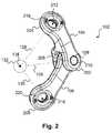
- FIG. 2is a perspective view of one embodiment of a brace that may be used in the dynamic stabilization system of FIG. 1 ;
- FIG. 3is a view of the brace illustrated in FIG. 2 in an extended position
- FIG. 4is a cross-sectional view of the brace of FIG. 3 ;
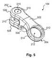
- FIG. 5is a detailed view of one embodiment of a member of the brace of FIG. 2 ;
- FIG. 6is a detailed view of one embodiment of a member of the brace of FIG. 2 ;
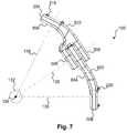
- FIG. 7is a side view of one embodiment of the brace of FIG. 2 ;
- FIG. 8is a side view of one embodiment of the dynamic stabilization system of FIG. 1 ;
- FIG. 9is an enlarged view of a portion of the dynamic stabilization system of FIG. 8 ;
- FIG. 10is a cross-sectional view of the portion of the dynamic stabilization system of FIG. 9 ;
- FIG. 11Ais a sagittal perspective view of the dynamic stabilization system illustrated in FIG. 1 in a neutral position;
- FIG. 11Bis a sagittal perspective view of the dynamic stabilization system illustrated in FIG. 1 in a flexion position;
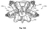
- FIG. 12Ais a posterior perspective view of the dynamic stabilization system illustrated in FIG. 1 in a neutral position
- FIG. 12Bis a posterior perspective view of the dynamic stabilization system illustrated in FIG. 1 in a flexion position
- FIG. 12Cis a posterior perspective view of the dynamic stabilization system illustrated in FIG. 1 in a rotation position
- FIG. 12Dis a posterior perspective view of the dynamic stabilization system illustrated in FIG. 1 in a lateral bending position
- FIG. 12Eis a posterior perspective view of the dynamic stabilization system illustrated in FIG. 1 in an extension position
- FIG. 13is a perspective view of another embodiment of a dynamic stabilization system
- FIG. 14is a cross-sectional view of one embodiment of the dynamic stabilization system of FIG. 13 ;
- FIG. 15Ais an exploded view of one embodiment of a locking assembly that may be used with the dynamic stabilization system of FIG. 13 ;
- FIG. 15Bis a cross-sectional view of one embodiment of the locking assembly of FIG. 15A in an assembled state
- FIGS. 16 and 17are a cross-sectional views of one embodiment of the dynamic stabilization system of FIG. 13 ;
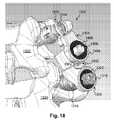
- FIG. 18is a perspective view of one embodiment of the dynamic stabilization system of FIG. 13 ;
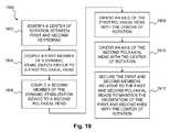
- FIG. 19is a flowchart of one embodiment of a method for using a dynamic stabilization system.
- Certain aspects of the present disclosureprovide dynamic stabilization systems, dynamic stabilization devices, and/or methods for maintaining spacing between consecutive neighboring vertebrae and stabilizing a spine, while allowing movement of the vertebrae relative to each other in at least two and preferably three axes of rotation.
- the neighboring vertebraemay be immediately next to each other or spaced from each other by one or more intervening vertebrae.
- a dynamic stabilization systemimplanted at a neutral position that allows for a minimum available range of motion, while having the system aligned with a center of rotation that is placed, for example, at the 60-70% A-P marker of a vertebral body.
- a sliding dynamic stabilization systemmay not have sufficient engagement left for flexion (i.e., the system may reach the end of the sliding motion before full flexion is achieved).
- the relative starting engagementmay be the same (e.g., neutral). This may also be desirable to ensure that dampening forces are consistent at both extremes of relative motion.
- a further change of pedicle to pedicle distance by another one millimetermay place the center of rotation at the 75% A-P mark, which may not be acceptable.
- multiple sizes with overlapping rangeswould have to be designed to accommodate all anatomy variations, align the center of rotation to the 60-70% A-P mark, and enable co-alignment of a dynamic stabilization system pair (i.e., left and right sides).
- dynamic stabilization systems, devices, and methods for dynamic stabilizationwhich may provide for adjustable distraction of the inter-vertebral space while still allowing a patient a substantial range of motion in two and/or three dimensions.
- a dynamic stabilization systemmay allow the vertebrae to which it is attached to move through a natural arc that may resemble an imaginary three dimensional surface such as a sphere or an ellipsoid. Accordingly, such a system may aid in permitting a substantial range of motion in flexion, extension, rotation, anterior-posterior translation and/or other desired types of natural spinal motion.
- the spine stabilization system 100may include a dynamic stabilization device 102 that includes two members 104 and 106 coupled by a pin 108 .
- the pin 108may enable the two members 104 and 106 to move with respect to one another, as will be described later in greater detail.
- Each member 104 and 106may be secured to a portion of a spine (not shown), such as a pedicle, by a fastening element such as a bone anchor (e.g., a pedicle screw) 110 and 112 , respectively.
- a bone anchore.g., a pedicle screw
- Each bone anchor 110 and 112may include or be attached to a polyaxial head, 114 and 116 , respectively.
- the member 104may be coupled to the polyaxial head 114 of its respective bone anchor 110 using, for example, a bearing post 118 (e.g., a set screw) and a locking nut 122 .
- the member 106may be coupled to the polyaxial head 116 of its respective bone anchor 112 using, for example, a bearing post 120 (e.g., a set screw) and a locking nut 124 .
- the pin 108may be aligned with a first axis 126 .
- the bearing posts 118 and 120may be aligned with a second axis 128 and a third axis 130 , respectively.
- the axes 126 , 128 , and 130may intersect at area 132 (e.g., an area of rotation).
- the axes 126 , 128 , and 130may intersect at a point 134 (e.g., a center of rotation) within the area 132 .
- the point 134may be stationary or may move within the area 132 in conjunction with movement of the vertebrae (not shown in FIG. 1 ) to which the spinal stabilization device 102 is coupled.
- the area 132 and the point 134are for purposes of illustration only and are not limited to the shapes or sizes shown.
- the area 132is shown as a sphere, the area may be an ellipsoid or other shape.
- the axes 126 , 128 , and 130are shown intersecting each other at the point 134 , it is understood that they may not actually intersect one another, but may instead pass within a certain distance of each other.
- the point 134need not be a stationary point, but may follow a path on or through the area 132 .
- the point 134may move along a surface of the area 132 such that the area 132 provides a shell, and movement of the point 134 is constrained by the device 102 to an outer surface of the shell.
- the term center of rotationmay be used herein to refer to a specific point and/or a three dimensional surface.
- the dynamic stabilization device 102may include two members 104 and 106 that are coupled via the pin 108 .
- the member 104may include a joint end 202 and a fastening end 204
- the member 106may include a joint end 206 and a fastening end 208 .
- the joint end 202 of the member 104may include one or more apertures 210 and the fastening end 204 of the member 104 may include an aperture 212 .
- the joint end 206 of the member 106may include an aperture 214 (shown in FIG.
- the fastening end 208 of the member 106may include an aperture 216 .
- the pin 108may couple the members 104 and 106 via insertion into the apertures 210 and 214 , respectively.
- the bearing posts 118 and 120(shown in FIG. 1 ) may be inserted into apertures 212 and 216 , respectively, to couple members 104 and 106 to pedicles or other bone (not shown in FIG. 2 ).
- one or more of the apertures 210 , 212 , 214 , and 216may contain a bushing or other insertion member 218 .
- the aperture 212may include a bushing 218 and the aperture 216 may include a bushing 220 .
- the bushings 218 and 220may aid in securing the dynamic stabilization device 102 to the bearing posts 118 and 120 (shown in FIG. 1 ).
- One or both of the bushings 218 and 220may be internally threaded to engage the respective bearing posts 118 and 120 .
- an external surface of the bushings 218 and 220may be relatively smooth to facilitate rotation of the respective members 104 and 106 around the bushings.
- the apertures 210 and 214may be aligned with the first axis 126 .
- the apertures 212 and 216may be aligned with the second axis 128 and third axis 130 , respectively. It is understood that, as the apertures 210 , 212 , 214 , and 216 may be aligned with their respective axes, the pin 108 and bearing posts 118 and 120 may be aligned with the axes due to their insertion into the respective apertures. Alternatively, the pin 108 and bearing posts 118 and 120 may be aligned with their respective axes, and their alignment may result in the alignment of their respective apertures.
- the spinal stabilization device 102 of FIG. 2is illustrated in a fully extended or lengthened position (e.g., during flexion).
- apertures 210 , 212 , and 216are aligned with axes 126 , 128 , and 130 , respectively, when in the fully extended position. Accordingly, the axes 126 , 128 , and 130 may intersect the point 134 and/or move along a surface provided by the area of rotation 132 as previously described.
- FIG. 4a cross-sectional view of one embodiment of the spinal stabilization device 102 of FIG. 3 is illustrated.
- the members 104 and 106may be coupled by the pin 108 .
- the bushings 218 and 220are positioned within the apertures 212 and 216 , respectively.
- a bushing cap 402may abut the bushing 218 and a bushing cap 404 may abut the bushing 220 .
- a bushing 406 in the aperture 214 and an abutting bushing cap 408In contrast to the illustrated bushings 218 and 220 , the bushing 406 may have a smooth bore (e.g., rather than threaded) to facilitate rotation with the pin 208 .
- the pin 108may couple the members 104 and 106 via insertion into the apertures 210 and 214 , respectively.
- the bearing posts 118 and 120may couple the members 104 and 106 to pedicles or other bone (not shown in FIG. 4 ) via apertures 212 and 216 , respectively.
- the member 104may include one or more apertures 210 at the joint end 202 and an aperture 212 at the fastening end 204 .
- the member 104provides a “Y” shape or yoke formed by branches 506 and 508 .
- the branches 506 and 508may be spaced apart to provide clearance for the end 206 of the member 106 .
- a medial portion of the member 104e.g., the portion forming the bottom of the yoke
- an upper surface 502 and a lower surface 504 of the member 104may be curved to align the apertures 210 and 212 with axes 126 and 128 (shown in FIG. 2 ), respectively, in order to accommodate the natural movement of the spine. It is understood that the curve may be defined differently depending on such factors as the length of the member 104 , the location of the apertures 210 and/or 212 , and the desired center of rotation for the dynamic stabilization device 102 .
- the inner walls 510 of the aperture 210may be relatively smooth to facilitate rotation of the member 104 with respect to the pin 108 .
- a bushing(shown in FIG. 4 ) may be provided to enhance the rotation of the pin 108 (not shown in FIG. 5 ) within the aperture 210 .
- the inner walls 512 of the aperture 212may contain ridges, grooves, threads, or other means for engaging the bushing 218 (shown in FIG. 2 ).
- the member 104may also include one or more beveled or otherwise shaped surfaces 514 .
- the member 106may include an aperture 214 at the joint end 206 and an aperture 216 at the fastening end 208 .
- the joint end 206may be sized to fit within a yoke (shown in FIG. 5 ) of the member 104 .
- an upper surface 602 and a lower surface 604 of the member 102may be curved to align the apertures 214 and 216 with axes 126 and 130 (shown in FIG. 2 ), respectively, in order to accommodate the natural movement of the spine. It is understood that the curve may be defined differently depending on such factors as the length of the member 106 , the location of the apertures 214 and/or 216 , and the desired center of rotation for the dynamic stabilization device 102 .
- the inner walls 606 of the aperture 214may be relatively smooth to facilitate rotation of the member 106 with respect to the pin 108 .
- a bushing(shown in FIG. 4 ) may be provided to enhance the rotation of the pin 108 within the aperture 214 .
- the inner walls 608 of the aperture 216may contain ridges, grooves, threads, or other means for engaging the bushing 220 (shown in FIG. 2 ).
- the member 106may also include one or more beveled or otherwise shaped surfaces 610 .
- FIG. 7a side view of one embodiment of the dynamic stabilization device 102 of FIG. 2 is illustrated.
- the members 104 and 106may be designed and arranged to align with axes 126 , 128 , and 130 .
- FIG. 8a side view of the dynamic stabilization system 100 of FIG. 1 is illustrated.
- the pin 108may be aligned with the axis 126
- the bearing posts 118 and 120may be aligned with axes 128 and 130 , respectively.
- the use of polyaxial heads 114 and 116enables the spinal stabilization device 102 to be oriented to the area 132 even though bone anchors 110 and 112 may be oriented along other axes. This flexibility enables a surgeon to insert the bone anchors 110 and 112 as desired while maintaining the movement of the spinal stabilization device 102 with respect to the area 132 and/or point 134 .
- FIGS. 9 and 10an enlarged view of a portion of the spinal stabilization device 102 of FIG. 8 is illustrated in side perspective and cross-sectional views, respectively.
- the bearing post 118may extend through the aperture 212 and into the polyaxial head 114 .
- the bushing 218 and bushing cap 402may be retained in the aperture 212 .
- the locking cap 122may be used to secure the member 104 to the bearing post 118 at a particular position, enabling a vertical height of the member 104 relative to the polyaxial head 114 to be adjusted.
- a distal portion of the bearing post 118may be tightened against the bone anchor 110 within the polyaxial head to lock the bone anchor into a desired position with respect to the polyaxial head 114 .
- the bone anchor 110Prior to the tightening of the bearing post 118 , the bone anchor 110 may move relatively freely within the polyaxial head 114 . Accordingly, the dynamic stabilization device 102 may be positioned and then the bearing post 118 may be tightened to lock the position of the dynamic stabilization device relative to the polyaxial head 114 and bone anchor 110 .
- FIGS. 11A and 11Bthere are shown sagittal views illustrating a range of motion and center of rotation between two neighboring vertebrae 1100 and 1102 linked by the spine stabilization system 100 of FIG. 1 .
- FIG. 11Aillustrates the spine stabilization system 100 when the two adjacent vertebrae 1100 and 1102 are in a neutral position.
- FIG. 11Billustrates the spine stabilization system 100 when the two adjacent vertebrae 1100 and 1102 are undergoing flexion (e.g., when the patient is bending forward).
- the spine stabilization system 100maintains alignment with the area 132 (e.g., with a center of rotation or with an area of rotation) regardless of the position of the two vertebrae 1100 and 1102 .
- FIGS. 12A-12Ethere are shown posterior views illustrating a range of motion and center of rotation between two neighboring vertebrae 1200 and 1202 linked by spine stabilization systems 100 a and 100 b .
- FIG. 12Aillustrates the spine stabilization systems 100 a and 100 b when the two adjacent vertebrae 1200 and 1202 are in a neutral position.
- FIG. 12Billustrates the spine stabilization systems 100 a and 100 b when the two adjacent vertebrae 1200 and 1202 are undergoing flexion (e.g., when the patient is bending forward).
- FIG. 12Cillustrates the spine stabilization systems 100 a and 100 b when the two adjacent vertebrae 1200 and 1202 are undergoing rotation (e.g., when the patient is turning to the right or left).
- FIG. 12Dillustrates the spine stabilization systems 100 a and 100 b when the two adjacent vertebrae 1200 and 1202 are in a lateral bending position (e.g., when the patient is bending towards the right or left).
- FIG. 12Eillustrates the spine stabilization systems 100 a and 100 b when the two adjacent vertebrae 1200 and 1202 are undergoing extension (e.g., when the patient is bending backward).
- the spine stabilization systems 100 a and 100 bmaintain alignment with the area 132 (e.g., with a center of rotation or with an area of rotation) regardless of the position of the two vertebrae 1200 and 1202 .
- a spine stabilization system 1300is illustrated.
- the spine stabilization system 1300may be fitted to varying anatomies while providing a consistent range of motion, consistent dampening forces at the extremes of motion, alignment with a desired center of rotation (e.g., 60-70% A-P), and co-alignment of left and right systems.
- the spine stabilization system 1300may provide height adjustment, spherical functionality, and/or sliding adjustment for variations in a patient's anatomy.
- the dynamic stabilization device 1302may include two anchor members 1304 and 1306 coupled by a sliding member 1308 .
- the sliding member 1308may enable the two anchor members 1304 and 1306 to move with respect to one another, as will be described later in greater detail.
- Each anchor member 1304 and 1306may be secured to a portion of a vertebral body 1322 and 1324 , respectively, such as a pedicle, via a fastening element such as a bone anchor (e.g., a pedicle screw) 1310 and 1312 , respectively.
- a bone anchore.g., a pedicle screw
- each bone anchor 1310 and 1312may include or be coupled to a polyaxial head 1314 and 1316 , respectively.
- the anchor members 1304 and 1306may then be coupled to their respective polyaxial head 1314 and 1316 to link each anchor member with a bone anchor.
- the polyaxial head 1314may include a slot or other opening for receiving a portion of the anchor member 1304 .
- the polyaxial head 1316may be configured to receive a bearing post 1318 (e.g., a locking screw), and the anchor member 1306 may couple to the polyaxial head via the bearing post and a threaded bearing element 1320 . It is understood that while the present example illustrates different configurations for coupling the anchor members 1304 and 1306 to their respective polyaxial heads 1314 and 1316 , a single configuration may be used in some embodiments.
- a bearing post 1318e.g., a locking screw
- the polyaxial heads 1314 and 1316 and/or the anchor members 1304 and 1306may be aligned with a center of rotation as described with respect to the dynamic stabilization device 100 of FIG. 1 . Accordingly, two and three dimensional movement of the anchor members 1304 and 1306 may be constrained to ensure that axes of the polyaxial heads 1314 and 1316 and/or the anchor members 1304 and 1306 remain aligned with the center of rotation.
- the dynamic stabilization device 1302may include two anchor members 1304 and 1306 that are coupled via the sliding member 1308 .
- the anchor member 1304may include an adjustable anchor portion 1402 and a dynamic portion 1404 joined by a middle portion 1406 . While the middle portion 1406 is illustrated as connecting to the adjustable anchor portion 1402 and dynamic portion 1404 at substantially ninety degree angles in the present embodiment, it is understood that other angles may be used. Furthermore, it is understood that a distance D 1 representing a distance (relative to the positioning illustrated in FIG. 14 ) between the adjustable anchor portion 1402 and dynamic portion 1404 may be varied from that shown.
- the adjustable anchor portion 1402 of the anchor member 1304may be sized to enter a slot ( 1804 of FIG. 18 ) in the polyaxial head 1314 . As will be described later, the adjustable anchor portion 1402 may be moved within the polyaxial head 1314 until a desired position is attained and then locked into place. Accordingly, a distance D 2 representing a distance between the polyaxial head 1314 and the middle portion 1406 may be varied as a position of the adjustable anchor portion 1402 varies with respect to the polyaxial head.
- the dynamic portion 1404 of the anchor member 1304may include an opening containing a threaded or non-threaded bearing element 1408 coupled (e.g., welded) to a bearing element 1410 .
- the bearing element 1410may serve to retain the bearing element 1408 in the opening.
- the bearing element 1408may include a bore sized to receive a portion of the sliding element 1308 .
- the bearing element 1408may be sized to allow the sliding element 1308 to rotate and slide within the bearing element's bore, enabling the anchor member 1304 to move relative to the sliding member 1308 .
- the anchor member 1306may include a cavity portion 1412 and an adjustable anchor portion 1414 .
- the cavity portion 1412may include a cavity 1416 running substantially along a longitudinal axis of the cavity portion 1412 , and the cavity 1416 may be sized to receive a portion of the sliding member 1308 .
- an upper part of the cavity portion 1412e.g., facing the underside of the dynamic portion 1404 of the anchor member 1304
- the adjustable anchor portion 1414may include an opening containing the threaded bearing element 1320 coupled (e.g., welded) to a bearing element 1418 .
- the bearing element 1418may serve to retain the threaded bearing element 1320 in the opening.
- the threaded bearing element 1320may include internal threads 1420 configured to engage external threads 1422 of the bearing post 1318 .
- a locking cap1502 of FIG. 15A ) may be used to lock a position of the anchor member 1306 relative to the bearing post 1318 at a variable distance D 3 between the adjustable anchor portion 1414 and the polyaxial head 1316 .
- the locking assembly 1500may include the bone anchor 1310 (e.g., a pedicle screw), polyaxial head 1316 , bearing post 1318 , threaded bearing element 1320 , bearing element 1418 , and locking cap 1502 .
- the bone anchor 1312may include a proximal portion 1504 and a distal portion 1506 .
- the proximal portion 1504may include a reverse thread that engages a compatible thread form within the polyaxial head 1316 .
- the polyaxial head 1316may move in relation to the bone anchor 1312 .
- the bone anchor 1312may further include an engagement portion 1508 .
- the polyaxial head 1316may include a proximal portion 1510 and a distal portion 1512 , both of which may be threaded.
- the proximal portion 1510may include a thread form different from that of the distal portion 1512 .
- the distal portion 1512may be threaded to receive the reverse thread of the proximal portion 1504 of the bone anchor 1312 .
- the proximal portion 1510may be threaded to receive a portion of the bearing post 1318 .
- the threads of the proximal portion 1510may be designed with anti-splay characteristics.
- the threadsmay be grooved to accept a dovetail shaped thread.
- the proximal portion 1510may be reverse threaded.
- the bearing post 1318may include a proximal portion 1514 and a distal portion 1516 , both of which may be threaded.
- the proximal portion 1514may include a thread form different from that of the distal portion 1516 .
- the distal portion 1516may include a thread form configured to engage the thread form of the proximal portion 1510 of the polyaxial head 1316 .
- the thread formis not reverse threaded in the present embodiment, it is understood that it may be reverse threaded in other embodiments.
- the proximal portion 1514may be threaded to engage the threaded bearing element 1320 and locking cap 1502 .
- the proximal end of the bearing post 1318may include one or more features 1518 . Such features 1518 may, for example, be used to engage a tool for rotating the bearing post 1318 .
- the threaded bearing element 1320may include internal threads ( 1534 of FIG. 15B ) configured to engage the proximal portion 1514 of the bearing post 1318 .
- the threaded bearing element 1320may have an exterior surface of varying diameters, including a proximal portion 1520 , a first intermediate portion 1522 , a second intermediate portion 1524 , and a distal portion 1526 .
- the distal portion 1526 and second intermediate portion 1524may abut the bearing element 1322 and the proximal portion 1520 and first intermediate portion 1522 may abut the anchor member 1306 .
- the anchor member 1306may rotate around the threaded bearing element.
- the locking cap 1502may include internal threads ( 1536 of FIG. 15B ) configured to engage the proximal portion 1514 of the bearing post 1318 .
- the locking cap 1502may have an exterior surface of varying diameters, including a proximal portion 1528 , an intermediate portion 1530 , and a distal portion 1532 .
- the intermediate portion 1530 and distal portion 1532may abut an interior surface of the threaded bearing element 1320 and the proximal portion 1528 may provide a surface for engaging a tool used to tighten the locking cap 1502 .
- the polyaxial head 1316may generally move relative to the bone anchor 1312 .
- the bearing post 1318may be inserted into the polyaxial head 1316 so that the threads of the distal portion 1516 of the bearing post engage the threads of the proximal portion 1510 of the polyaxial head.
- the bearing post 1318may then be tightened until the distal end (which may be concave in the present example) contacts the engagement portion 1508 of the bone anchor 1312 . This locks the position of the polyaxial head 1316 relative to the bone anchor 1312 .
- the threaded bearing element 1320may not contact the polyaxial head 1316 . More specifically, the position of the threaded bearing element 1320 may be adjusted along a longitudinal axis of the bearing post 1318 to vary the distance D 3 that exists between the threaded bearing element and the polyaxial head 1316 . This enables a height of the anchor member 1306 relative to the polyaxial head 1316 to be varied and allows for adjustments to be made to the dynamic stabilization device 1302 .
- the locking cap 1502may be rotated along the longitudinal axis of the bearing post 1318 to the desired position and tightened against the threaded bearing element 1320 . As illustrated, intermediate portion 1530 and distal portion 1532 of the exterior surface of the locking cap 1502 may enter a bore of the threaded bearing element 1320 and lock against an internal surface of the threaded bearing element. This may lock the threaded bearing element 1320 into place relative to the polyaxial head 1316 and may maintain the distance D 3 as set.
- the sliding portion 1308may include a first portion 1424 that extends into the dynamic portion 1404 of the anchor member 1304 and a second portion 1426 that extends into the cavity portion 1412 of the anchor member 1306 .
- the first portion 1424may be configured with a length D 4 that may fit within the bearing element 1408
- the second portion 1426may be configured with a length D 5 that may fit within the cavity 1416 .
- the first and second portions 1424 and 1426form a substantially ninety degree angle, but it is understood that other angles may be used.
- the first and second portions 1424 and 1426may be captured within the dynamic portion 1404 and cavity portion 1412 by the positioning of the anchor members 1304 and 1306 and/or by other means.
- a maximum change of position between the vertebral bodies 1322 and 1324 along a longitudinal axis of the portion 1424may be less than the length D 4 .
- a maximum change of position between the vertebral bodies 1322 and 1324 along a longitudinal axis of the portion 1426may be less than the length D 5 .
- additional meanse.g., a retaining ring, retaining pin, or elastic sleeve
- a retaining ring, retaining pin, or elastic sleevemay be provided to capture the first portion 1424 and/or second portion 1426 within the dynamic portion 1404 and cavity portion 1412 , respectively.
- FIG. 16another cross-sectional view of the dynamic stabilization device 1302 illustrates the sliding member 1308 in greater detail.
- the portion 1424 of the sliding member 1308may have a first diameter represented by arrow 1600 and a second diameter represented by arrow 1602 .
- the first diameter 1600which is sized to fit within the bearing element 1408 , may be smaller than the second diameter 1602 , which is larger than the bore of the bearing element. Accordingly, the diameter 1602 may prevent the dynamic portion 1404 from contacting the cavity portion 1412 .
- a sloped neck 1604may join the two diameters.
- a slot 1606may be sized to enable movement of the portion 1424 along a longitudinal axis of the cavity portion 1412 .
- the illustrated cross-sectionsmay be varied.
- the portion 1424is substantially cylindrical and the portion 1426 is substantially rectangular.
- the adjustable anchor portion 1402is substantially cylindrical.
- these cross-sectional shapesare for purposes of example only and other shapes may be used.
- various featurese.g., grooves and/or protrusions may be provided on the surface of the adjustable anchor portion and/or other components.
- the adjustable anchor portion 1402may be inserted into the polyaxial head 1314 . Adjustment of the anchor member 1304 may then occur along a longitudinal axis (represented by arrow 1700 ) of the adjustable anchor portion 1402 . Once correctly positioned, a locking nut or other locking means configured to engage threads within the polyaxial head 1314 may be tightened. The tightening may lock the adjustable anchor portion 1402 into place within the polyaxial head 1314 .
- the tighteningmay also force the adjustable anchor portion 1402 against the bone anchor 1310 , preventing movement between the bone anchor and the polyaxial head 1314 .
- the bone anchor 1310 and polyaxial head 1314may be locked into place prior to locking the adjustable anchor portion 1402 into place.
- the adjustable anchor portion 1414may be positioned as desired along a longitudinal axis (represented by arrow 1702 ) of the bearing post 1318 .
- the adjustable anchor portion 1414may be locked into placed with respect to the polyaxial head 1316 using the locking cap 1502 (shown in FIG. 15B ), preventing further movement along the longitudinal axis 1702 .
- the anchor portion 1304may be locked into position relative to the bone anchor 1310 and the anchor portion 1306 may be locked into position relative to the bone anchor 1312 .
- the adjustable anchor portion 1414 of the anchor member 1306may still be able to rotate around the longitudinal axis 1702 .
- the anchor portions 1304 and 1306may be locked into position relative to their respective bone anchors 1310 and 1312 , they may still move with respect to one another due to the sliding member 1308 .
- the anchor members 1304 and 1306may move with respect to one another in a first direction along a longitudinal axis (represented by arrow 1704 ) of the portion 1424 as the portion 1424 moves within the bearing element 1408 .
- the anchor member 1304may also rotate at least partially around the longitudinal axis 1704 .
- the anchor members 1304 and 1306may move with respect to one another in a second direction along a longitudinal axis (represented by arrow 1706 ) of the portion 1426 as the portion 1426 moves within the cavity 1416 .
- the longitudinal axis 1706(and the other longitudinal axes) may actually be curved, and so the movement may be along a curved path rather than a straight line.
- the anchor member 1304may rotate and slide with respect to the anchor member 1306 within the range provided by the sliding member 1308 , and the anchor member 1306 may rotate with respect to the bearing post 1318 .
- such movementmay be limited. It is understood that such movement may occur simultaneously or separately (e.g., rotation around and/or movement may occur around one or both axes 1702 and 1704 , and/or along one or both axes 1704 and 1706 ).
- the sliding member 1308may move with respect to the anchor member 1306 .
- the anchor member 1306may include an indentation 1800 having a curved profile that substantially matches a curved outer surface 1802 of the dynamic portion 1404 of the anchor member 1304 . Accordingly, the anchor member 1304 may move towards the anchor member 1306 until the outer surface 1802 contacts the indentation 1800 . It is noted that, due to the substantially similar curves of the outer surface 1802 and indentation 1800 , the anchor member 1304 may rotate around the sliding member 1308 even when in contact with the anchor member 1306 .
- a method 1900may be used to insert a dynamic stabilization system, such as the dynamic stabilization system 100 of FIG. 1 or 1300 of FIG. 13 .
- a center of rotationmay be identified between first and second vertebrae.
- a first member of a dynamic stabilization devicemay be coupled to a first polyaxial head and, in step 1906 , a second member of the dynamic stabilization device may be coupled to a second polyaxial head.
- steps 1908 and 1910respectively, an axis of each of the first and second polyaxial heads may be oriented with the center of rotation.
- the first and second membersmay be secured relative to the first and second polyaxial heads, respectively, to maintain the orientation of the first and second axes with the center of rotation.
- a dynamic stabilization devicemay be inserted.
- the dynamic stabilization devicemay be designed to be coupled to bone anchors inserted into neighboring vertebrae.
- the dynamic stabilization devicemay include a bottom member and a top member that may be coupled together at the proximal ends thereof to allow relative rotation at least about both an axis of roll and a horizontal axis within a range of movement, the range of movement allowing lateral bending and twisting of the upper and lower vertebrae relative to each other while maintaining separation between the vertebrae.
- the distal end of the bottom membermay be coupled to a lower bone anchor and the distal end of the upper member may be coupled to an upper bone anchor.
- the upper and lower links memberbe coupled to the bone anchors via a threaded fastener and bushings.
- the threaded fastenermay comprise a bearing post secured by a locking cap or other similar threaded fasteners and locking mechanisms known to those skilled in the art.
- Both the upper and lower membermay be vertically adjusted along the threaded fastener during adjustment of the dynamic stabilization device and thereafter locked down into a substantially permanent position once the device is aligned with the spine's natural center of rotation.
- the devicemay be aligned with the spine natural center of rotation. This may be accomplished by several methods, including but not limited to using an aligning cross-connector, using a removable alignment tool that is coupled to the bone anchors, using a removable alignment tool coupled to the dynamic stabilization device between the bone anchors, or various other alignment methods known to those skilled in the art.
- the alignment toolmay be coupled to the dynamic stabilization device and then an alignment rod may be attached thereto.
- the alignment rodmay be rotated to adjust various components of the dynamic stabilization device such that the components of the dynamic stabilization device align with the spine's natural center of rotation.
- an alignment tool coupled to the bone anchorsmay be used to align the bone anchors before any other components of the dynamic stabilization device are implanted.
Landscapes
- Health & Medical Sciences (AREA)
- Orthopedic Medicine & Surgery (AREA)
- Life Sciences & Earth Sciences (AREA)
- Neurology (AREA)
- Surgery (AREA)
- Heart & Thoracic Surgery (AREA)
- Engineering & Computer Science (AREA)
- Biomedical Technology (AREA)
- Nuclear Medicine, Radiotherapy & Molecular Imaging (AREA)
- Medical Informatics (AREA)
- Molecular Biology (AREA)
- Animal Behavior & Ethology (AREA)
- General Health & Medical Sciences (AREA)
- Public Health (AREA)
- Veterinary Medicine (AREA)
- Surgical Instruments (AREA)
Abstract
Description
Claims (23)
Priority Applications (1)
| Application Number | Priority Date | Filing Date | Title |
|---|---|---|---|
| US11/693,394US8025681B2 (en) | 2006-03-29 | 2007-03-29 | Dynamic motion spinal stabilization system |
Applications Claiming Priority (6)
| Application Number | Priority Date | Filing Date | Title |
|---|---|---|---|
| US78689806P | 2006-03-29 | 2006-03-29 | |
| US83187906P | 2006-07-19 | 2006-07-19 | |
| US82507806P | 2006-09-08 | 2006-09-08 | |
| US82681706P | 2006-09-25 | 2006-09-25 | |
| US82680706P | 2006-09-25 | 2006-09-25 | |
| US11/693,394US8025681B2 (en) | 2006-03-29 | 2007-03-29 | Dynamic motion spinal stabilization system |
Publications (2)
| Publication Number | Publication Date |
|---|---|
| US20070233094A1 US20070233094A1 (en) | 2007-10-04 |
| US8025681B2true US8025681B2 (en) | 2011-09-27 |
Family
ID=38560259
Family Applications (1)
| Application Number | Title | Priority Date | Filing Date |
|---|---|---|---|
| US11/693,394Active2028-12-06US8025681B2 (en) | 2006-03-29 | 2007-03-29 | Dynamic motion spinal stabilization system |
Country Status (1)
| Country | Link |
|---|---|
| US (1) | US8025681B2 (en) |
Cited By (41)
| Publication number | Priority date | Publication date | Assignee | Title |
|---|---|---|---|---|
| US20080140075A1 (en)* | 2006-12-07 | 2008-06-12 | Ensign Michael D | Press-On Pedicle Screw Assembly |
| US20080195213A1 (en)* | 2007-02-12 | 2008-08-14 | Brigham Young University | Spinal implant |
| US20100211106A1 (en)* | 2009-02-19 | 2010-08-19 | Bowden Anton E | Compliant Dynamic Spinal Implant And Associated Methods |
| US20100217334A1 (en)* | 2009-02-23 | 2010-08-26 | Hawkes David T | Press-On Link For Surgical Screws |
| US20100241232A1 (en)* | 2007-02-12 | 2010-09-23 | Peter Halverson | Spinal implant |
| US8172885B2 (en) | 2003-02-05 | 2012-05-08 | Pioneer Surgical Technology, Inc. | Bone plate system |
| US8361126B2 (en) | 2007-07-03 | 2013-01-29 | Pioneer Surgical Technology, Inc. | Bone plate system |
| US20130041469A1 (en)* | 2011-08-11 | 2013-02-14 | Jeff Phelps | Interbody axis cage |
| US20130090690A1 (en)* | 2011-10-06 | 2013-04-11 | David A. Walsh | Dynamic Rod Assembly |
| US8444681B2 (en) | 2009-06-15 | 2013-05-21 | Roger P. Jackson | Polyaxial bone anchor with pop-on shank, friction fit retainer and winged insert |
| US8613760B2 (en) | 2005-09-30 | 2013-12-24 | Roger P. Jackson | Dynamic stabilization connecting member with slitted core and outer sleeve |
| US8623019B2 (en) | 2007-07-03 | 2014-01-07 | Pioneer Surgical Technology, Inc. | Bone plate system |
| US20140074169A1 (en)* | 2012-09-13 | 2014-03-13 | Warsaw Orthopedic, Inc. | Spinal correction system and method |
| US8894687B2 (en) | 2011-04-25 | 2014-11-25 | Nexus Spine, L.L.C. | Coupling system for surgical construct |
| US8911479B2 (en) | 2012-01-10 | 2014-12-16 | Roger P. Jackson | Multi-start closures for open implants |
| US8979904B2 (en) | 2007-05-01 | 2015-03-17 | Roger P Jackson | Connecting member with tensioned cord, low profile rigid sleeve and spacer with torsion control |
| US20150164557A1 (en)* | 2004-02-17 | 2015-06-18 | Gmedelaware 2 Llc | Facet joint replacement instruments and methods |
| US9157497B1 (en) | 2009-10-30 | 2015-10-13 | Brigham Young University | Lamina emergent torsional joint and related methods |
| US9168069B2 (en) | 2009-06-15 | 2015-10-27 | Roger P. Jackson | Polyaxial bone anchor with pop-on shank and winged insert with lower skirt for engaging a friction fit retainer |
| US9216041B2 (en) | 2009-06-15 | 2015-12-22 | Roger P. Jackson | Spinal connecting members with tensioned cords and rigid sleeves for engaging compression inserts |
| US20160022324A1 (en)* | 2013-11-13 | 2016-01-28 | Ant Technology | Interspinous fusion implant |
| US9333008B2 (en) | 2010-02-19 | 2016-05-10 | Brigham Young University | Serpentine spinal stability device |
| US9480517B2 (en) | 2009-06-15 | 2016-11-01 | Roger P. Jackson | Polyaxial bone anchor with pop-on shank, shank, friction fit retainer, winged insert and low profile edge lock |
| US9642719B1 (en)* | 2012-11-07 | 2017-05-09 | Costello Law Corporation | Spinal fusion system for osteoporotic vertebrae |
| US9642651B2 (en) | 2014-06-12 | 2017-05-09 | Brigham Young University | Inverted serpentine spinal stability device and associated methods |
| US9743957B2 (en) | 2004-11-10 | 2017-08-29 | Roger P. Jackson | Polyaxial bone screw with shank articulation pressure insert and method |
| US20180125533A1 (en)* | 2015-04-17 | 2018-05-10 | Apifix Ltd. | Expandable polyaxial spinal system |
| US9980753B2 (en) | 2009-06-15 | 2018-05-29 | Roger P Jackson | pivotal anchor with snap-in-place insert having rotation blocking extensions |
| US20180214185A1 (en)* | 2016-03-17 | 2018-08-02 | Medos International Sarl | Multipoint fixation implants |
| US20180250034A1 (en)* | 2014-09-19 | 2018-09-06 | In Queue Innovations, Llc | Single level fusion systems and methods of assembly and use |
| US10194951B2 (en) | 2005-05-10 | 2019-02-05 | Roger P. Jackson | Polyaxial bone anchor with compound articulation and pop-on shank |
| US10383660B2 (en) | 2007-05-01 | 2019-08-20 | Roger P. Jackson | Soft stabilization assemblies with pretensioned cords |
| US10898232B2 (en) | 2018-03-20 | 2021-01-26 | Medos International Sàrl | Multipoint fixation implants and related methods |
| US11123116B2 (en)* | 2013-12-09 | 2021-09-21 | Acumed Llc | Bone plate with movable joint |
| US11185350B2 (en) | 2016-08-15 | 2021-11-30 | Triqueue Holdings, Llc | Bone fusion device, system and methods |
| US11304728B2 (en) | 2020-02-14 | 2022-04-19 | Medos International Sarl | Integrated multipoint fixation screw |
| US11317948B2 (en) | 2014-09-19 | 2022-05-03 | In Queue Innovations, Llc | Fusion systems and methods of assembly and use |
| US11426210B2 (en) | 2019-09-25 | 2022-08-30 | Medos International Sàrl | Multipoint angled fixation implants for multiple screws and related methods |
| US11547450B2 (en) | 2015-04-17 | 2023-01-10 | Apifix Ltd. | Expandable polyaxial spinal system |
| US11877779B2 (en) | 2020-03-26 | 2024-01-23 | Xtant Medical Holdings, Inc. | Bone plate system |
| US12201332B2 (en) | 2013-12-09 | 2025-01-21 | Acumed Llc | Bone plate with movable joint |
Families Citing this family (80)
| Publication number | Priority date | Publication date | Assignee | Title |
|---|---|---|---|---|
| US7833250B2 (en) | 2004-11-10 | 2010-11-16 | Jackson Roger P | Polyaxial bone screw with helically wound capture connection |
| US8353932B2 (en) | 2005-09-30 | 2013-01-15 | Jackson Roger P | Polyaxial bone anchor assembly with one-piece closure, pressure insert and plastic elongate member |
| US10729469B2 (en) | 2006-01-09 | 2020-08-04 | Roger P. Jackson | Flexible spinal stabilization assembly with spacer having off-axis core member |
| US8292926B2 (en) | 2005-09-30 | 2012-10-23 | Jackson Roger P | Dynamic stabilization connecting member with elastic core and outer sleeve |
| US7862587B2 (en) | 2004-02-27 | 2011-01-04 | Jackson Roger P | Dynamic stabilization assemblies, tool set and method |
| US10258382B2 (en) | 2007-01-18 | 2019-04-16 | Roger P. Jackson | Rod-cord dynamic connection assemblies with slidable bone anchor attachment members along the cord |
| US8876868B2 (en) | 2002-09-06 | 2014-11-04 | Roger P. Jackson | Helical guide and advancement flange with radially loaded lip |
| WO2006052796A2 (en) | 2004-11-10 | 2006-05-18 | Jackson Roger P | Helical guide and advancement flange with break-off extensions |
| US7621918B2 (en) | 2004-11-23 | 2009-11-24 | Jackson Roger P | Spinal fixation tool set and method |
| US7377923B2 (en) | 2003-05-22 | 2008-05-27 | Alphatec Spine, Inc. | Variable angle spinal screw assembly |
| US7967850B2 (en) | 2003-06-18 | 2011-06-28 | Jackson Roger P | Polyaxial bone anchor with helical capture connection, insert and dual locking assembly |
| US8092500B2 (en) | 2007-05-01 | 2012-01-10 | Jackson Roger P | Dynamic stabilization connecting member with floating core, compression spacer and over-mold |
| US8366753B2 (en) | 2003-06-18 | 2013-02-05 | Jackson Roger P | Polyaxial bone screw assembly with fixed retaining structure |
| US7766915B2 (en) | 2004-02-27 | 2010-08-03 | Jackson Roger P | Dynamic fixation assemblies with inner core and outer coil-like member |
| US8926670B2 (en) | 2003-06-18 | 2015-01-06 | Roger P. Jackson | Polyaxial bone screw assembly |
| US7527638B2 (en) | 2003-12-16 | 2009-05-05 | Depuy Spine, Inc. | Methods and devices for minimally invasive spinal fixation element placement |
| US11419642B2 (en) | 2003-12-16 | 2022-08-23 | Medos International Sarl | Percutaneous access devices and bone anchor assemblies |
| US7179261B2 (en) | 2003-12-16 | 2007-02-20 | Depuy Spine, Inc. | Percutaneous access devices and bone anchor assemblies |
| US7160300B2 (en) | 2004-02-27 | 2007-01-09 | Jackson Roger P | Orthopedic implant rod reduction tool set and method |
| US11241261B2 (en) | 2005-09-30 | 2022-02-08 | Roger P Jackson | Apparatus and method for soft spinal stabilization using a tensionable cord and releasable end structure |
| US8152810B2 (en) | 2004-11-23 | 2012-04-10 | Jackson Roger P | Spinal fixation tool set and method |
| JP2007525274A (en) | 2004-02-27 | 2007-09-06 | ロジャー・ピー・ジャクソン | Orthopedic implant rod reduction instrument set and method |
| US7651502B2 (en) | 2004-09-24 | 2010-01-26 | Jackson Roger P | Spinal fixation tool set and method for rod reduction and fastener insertion |
| US8926672B2 (en) | 2004-11-10 | 2015-01-06 | Roger P. Jackson | Splay control closure for open bone anchor |
| WO2006057837A1 (en) | 2004-11-23 | 2006-06-01 | Jackson Roger P | Spinal fixation tool attachment structure |
| US7901437B2 (en) | 2007-01-26 | 2011-03-08 | Jackson Roger P | Dynamic stabilization member with molded connection |
| US10076361B2 (en) | 2005-02-22 | 2018-09-18 | Roger P. Jackson | Polyaxial bone screw with spherical capture, compression and alignment and retention structures |
| US8257355B2 (en)* | 2006-06-07 | 2012-09-04 | Spinefrontier Inc. | Methods and devices for static or dynamic spine stabilization |
| US20080058808A1 (en) | 2006-06-14 | 2008-03-06 | Spartek Medical, Inc. | Implant system and method to treat degenerative disorders of the spine |
| CA2670988C (en) | 2006-12-08 | 2014-03-25 | Roger P. Jackson | Tool system for dynamic spinal implants |
| US8475498B2 (en) | 2007-01-18 | 2013-07-02 | Roger P. Jackson | Dynamic stabilization connecting member with cord connection |
| US8366745B2 (en) | 2007-05-01 | 2013-02-05 | Jackson Roger P | Dynamic stabilization assembly having pre-compressed spacers with differential displacements |
| US8012177B2 (en) | 2007-02-12 | 2011-09-06 | Jackson Roger P | Dynamic stabilization assembly with frusto-conical connection |
| US20090105762A1 (en)* | 2007-10-23 | 2009-04-23 | Jackson Roger P | Dynamic stabilization member with fin supported segment |
| GB0707285D0 (en)* | 2007-04-17 | 2007-05-23 | Burke John | Implantable apparatus for modulation of skeletal growth |
| CA2690038C (en) | 2007-05-31 | 2012-11-27 | Roger P. Jackson | Dynamic stabilization connecting member with pre-tensioned solid core |
| US8048128B2 (en) | 2007-06-05 | 2011-11-01 | Spartek Medical, Inc. | Revision system and method for a dynamic stabilization and motion preservation spinal implantation system and method |
| US8048115B2 (en) | 2007-06-05 | 2011-11-01 | Spartek Medical, Inc. | Surgical tool and method for implantation of a dynamic bone anchor |
| US8083772B2 (en) | 2007-06-05 | 2011-12-27 | Spartek Medical, Inc. | Dynamic spinal rod assembly and method for dynamic stabilization of the spine |
| US8052722B2 (en) | 2007-06-05 | 2011-11-08 | Spartek Medical, Inc. | Dual deflection rod system for a dynamic stabilization and motion preservation spinal implantation system and method |
| US8109970B2 (en) | 2007-06-05 | 2012-02-07 | Spartek Medical, Inc. | Deflection rod system with a deflection contouring shield for a spine implant and method |
| US8092501B2 (en) | 2007-06-05 | 2012-01-10 | Spartek Medical, Inc. | Dynamic spinal rod and method for dynamic stabilization of the spine |
| US8021396B2 (en) | 2007-06-05 | 2011-09-20 | Spartek Medical, Inc. | Configurable dynamic spinal rod and method for dynamic stabilization of the spine |
| US8048123B2 (en) | 2007-06-05 | 2011-11-01 | Spartek Medical, Inc. | Spine implant with a deflection rod system and connecting linkages and method |
| US8114134B2 (en) | 2007-06-05 | 2012-02-14 | Spartek Medical, Inc. | Spinal prosthesis having a three bar linkage for motion preservation and dynamic stabilization of the spine |
| US8911477B2 (en) | 2007-10-23 | 2014-12-16 | Roger P. Jackson | Dynamic stabilization member with end plate support and cable core extension |
| US8808332B2 (en)* | 2012-12-31 | 2014-08-19 | Globus Medical, Inc. | Method for stabilizing the spine |
| US8333792B2 (en) | 2008-02-26 | 2012-12-18 | Spartek Medical, Inc. | Load-sharing bone anchor having a deflectable post and method for dynamic stabilization of the spine |
| US8211155B2 (en) | 2008-02-26 | 2012-07-03 | Spartek Medical, Inc. | Load-sharing bone anchor having a durable compliant member and method for dynamic stabilization of the spine |
| US8048125B2 (en) | 2008-02-26 | 2011-11-01 | Spartek Medical, Inc. | Versatile offset polyaxial connector and method for dynamic stabilization of the spine |
| US8007518B2 (en) | 2008-02-26 | 2011-08-30 | Spartek Medical, Inc. | Load-sharing component having a deflectable post and method for dynamic stabilization of the spine |
| US8097024B2 (en) | 2008-02-26 | 2012-01-17 | Spartek Medical, Inc. | Load-sharing bone anchor having a deflectable post and method for stabilization of the spine |
| US8267979B2 (en) | 2008-02-26 | 2012-09-18 | Spartek Medical, Inc. | Load-sharing bone anchor having a deflectable post and axial spring and method for dynamic stabilization of the spine |
| US8057517B2 (en) | 2008-02-26 | 2011-11-15 | Spartek Medical, Inc. | Load-sharing component having a deflectable post and centering spring and method for dynamic stabilization of the spine |
| US8337536B2 (en) | 2008-02-26 | 2012-12-25 | Spartek Medical, Inc. | Load-sharing bone anchor having a deflectable post with a compliant ring and method for stabilization of the spine |
| US8083775B2 (en) | 2008-02-26 | 2011-12-27 | Spartek Medical, Inc. | Load-sharing bone anchor having a natural center of rotation and method for dynamic stabilization of the spine |
| US8202299B2 (en) | 2008-03-19 | 2012-06-19 | Collabcom II, LLC | Interspinous implant, tools and methods of implanting |
| AU2010260521C1 (en) | 2008-08-01 | 2013-08-01 | Roger P. Jackson | Longitudinal connecting member with sleeved tensioned cords |
| EP2323573B1 (en)* | 2008-09-18 | 2012-01-18 | Synthes GmbH | Anterior transpedicular screw-and-plate system |
| US9668771B2 (en) | 2009-06-15 | 2017-06-06 | Roger P Jackson | Soft stabilization assemblies with off-set connector |
| US8998959B2 (en) | 2009-06-15 | 2015-04-07 | Roger P Jackson | Polyaxial bone anchors with pop-on shank, fully constrained friction fit retainer and lock and release insert |
| US11229457B2 (en) | 2009-06-15 | 2022-01-25 | Roger P. Jackson | Pivotal bone anchor assembly with insert tool deployment |
| EP2485654B1 (en) | 2009-10-05 | 2021-05-05 | Jackson P. Roger | Polyaxial bone anchor with non-pivotable retainer and pop-on shank, some with friction fit |
| CN102695465A (en) | 2009-12-02 | 2012-09-26 | 斯帕泰克医疗股份有限公司 | Low profile spinal prosthesis incorporating a bone anchor having a deflectable post and a compound spinal rod |
| US20110307015A1 (en) | 2010-06-10 | 2011-12-15 | Spartek Medical, Inc. | Adaptive spinal rod and methods for stabilization of the spine |
| AU2011299558A1 (en) | 2010-09-08 | 2013-05-02 | Roger P. Jackson | Dynamic stabilization members with elastic and inelastic sections |
| AU2011324058A1 (en) | 2010-11-02 | 2013-06-20 | Roger P. Jackson | Polyaxial bone anchor with pop-on shank and pivotable retainer |
| US8430916B1 (en) | 2012-02-07 | 2013-04-30 | Spartek Medical, Inc. | Spinal rod connectors, methods of use, and spinal prosthesis incorporating spinal rod connectors |
| US8911478B2 (en) | 2012-11-21 | 2014-12-16 | Roger P. Jackson | Splay control closure for open bone anchor |
| US10058354B2 (en) | 2013-01-28 | 2018-08-28 | Roger P. Jackson | Pivotal bone anchor assembly with frictional shank head seating surfaces |
| US8852239B2 (en) | 2013-02-15 | 2014-10-07 | Roger P Jackson | Sagittal angle screw with integral shank and receiver |
| US9775650B2 (en)* | 2013-03-11 | 2017-10-03 | Dynamic Spine, Llc | Screw clamp orthopedic device and methods of implementation |
| US9566092B2 (en) | 2013-10-29 | 2017-02-14 | Roger P. Jackson | Cervical bone anchor with collet retainer and outer locking sleeve |
| US9717533B2 (en) | 2013-12-12 | 2017-08-01 | Roger P. Jackson | Bone anchor closure pivot-splay control flange form guide and advancement structure |
| US9451993B2 (en) | 2014-01-09 | 2016-09-27 | Roger P. Jackson | Bi-radial pop-on cervical bone anchor |
| WO2015187123A1 (en)* | 2014-06-02 | 2015-12-10 | Albany Medical College | Dynamic decompressive craniotomy fixation devices and related methods |
| US9597119B2 (en) | 2014-06-04 | 2017-03-21 | Roger P. Jackson | Polyaxial bone anchor with polymer sleeve |
| US10064658B2 (en) | 2014-06-04 | 2018-09-04 | Roger P. Jackson | Polyaxial bone anchor with insert guides |
| US10238432B2 (en)* | 2017-02-10 | 2019-03-26 | Medos International Sàrl | Tandem rod connectors and related methods |
| CN112190321A (en)* | 2020-05-26 | 2021-01-08 | 陆金明 | Minimally invasive chain type stabilizing device for lumbar artificial slippage |
Citations (274)
| Publication number | Priority date | Publication date | Assignee | Title |
|---|---|---|---|---|
| US3426364A (en) | 1966-08-25 | 1969-02-11 | Colorado State Univ Research F | Prosthetic appliance for replacing one or more natural vertebrae |
| US3807394A (en) | 1971-08-19 | 1974-04-30 | Nat Res Dev | Fracture fixing device |
| US3920060A (en) | 1973-07-11 | 1975-11-18 | Veeder Industries Inc | Cup-point fastener |
| US4157715A (en) | 1977-03-25 | 1979-06-12 | Erhard Westerhoff | Intracorporal drive to produce a continuous traction or pressure and method of operating the same |
| US4854311A (en) | 1986-01-09 | 1989-08-08 | Acro Med Corporation | Bone screw |
| US5011484A (en) | 1987-11-16 | 1991-04-30 | Breard Francis H | Surgical implant for restricting the relative movement of vertebrae |
| US5019080A (en) | 1990-02-13 | 1991-05-28 | Trextron Inc. | Drive system for prosthetic fasteners |
| US5053036A (en) | 1987-11-03 | 1991-10-01 | Synthes (U.S.A.) | Point contact bone compression plate |
| EP0322334B1 (en) | 1987-12-23 | 1992-02-26 | Cremascoli France | Prosthesis implanted between vertebral spinous processes |
| US5092867A (en) | 1988-07-13 | 1992-03-03 | Harms Juergen | Correction and supporting apparatus, in particular for the spinal column |
| US5129899A (en) | 1991-03-27 | 1992-07-14 | Smith & Nephew Richards Inc. | Bone fixation apparatus |
| US5129900A (en) | 1990-07-24 | 1992-07-14 | Acromed Corporation | Spinal column retaining method and apparatus |
| US5151103A (en) | 1987-11-03 | 1992-09-29 | Synthes (U.S.A.) | Point contact bone compression plate |
| US5176679A (en) | 1991-09-23 | 1993-01-05 | Lin Chih I | Vertebral locking and retrieving system |
| US5196013A (en) | 1989-11-03 | 1993-03-23 | Harms Juergen | Pedicel screw and correcting and supporting apparatus comprising such screw |
| US5257994A (en) | 1991-09-23 | 1993-11-02 | Lin Chih I | Vertebral locking and retrieving system |
| US5261909A (en) | 1992-02-18 | 1993-11-16 | Danek Medical, Inc. | Variable angle screw for spinal implant system |
| US5300073A (en) | 1990-10-05 | 1994-04-05 | Salut, Ltd. | Sacral implant system |
| US5304179A (en) | 1993-06-17 | 1994-04-19 | Amei Technologies Inc. | System and method for installing a spinal fixation system at variable angles |
| US5330474A (en) | 1991-09-23 | 1994-07-19 | Lin Chih I | Vertebral locking and retrieving system |
| US5375823A (en) | 1992-06-25 | 1994-12-27 | Societe Psi | Application of an improved damper to an intervertebral stabilization device |
| US5380324A (en) | 1992-05-18 | 1995-01-10 | Pina Vertriebs Ag | Implantable device for straightening and fixing vertebrae |
| US5403314A (en) | 1993-02-05 | 1995-04-04 | Acromed Corporation | Apparatus for retaining spinal elements in a desired spatial relationship |
| US5413576A (en) | 1993-02-10 | 1995-05-09 | Rivard; Charles-Hilaire | Apparatus for treating spinal disorder |
| US5413602A (en) | 1991-09-30 | 1995-05-09 | Howmedica Gmbh | Vertebral body spacer device |
| US5415661A (en) | 1993-03-24 | 1995-05-16 | University Of Miami | Implantable spinal assist device |
| US5423816A (en) | 1993-07-29 | 1995-06-13 | Lin; Chih I. | Intervertebral locking device |
| US5435680A (en) | 1991-07-24 | 1995-07-25 | Adolf Wurth Gmbh & Co. Kg | Screw drive construction |
| US5474551A (en) | 1994-11-18 | 1995-12-12 | Smith & Nephew Richards, Inc. | Universal coupler for spinal fixation |
| US5474553A (en) | 1989-04-18 | 1995-12-12 | Rainer Baumgart | System for setting tubular bone fractures |
| US5476463A (en) | 1994-01-12 | 1995-12-19 | Acromed Corporation | Spinal column retaining apparatus |
| US5480401A (en) | 1993-02-17 | 1996-01-02 | Psi | Extra-discal inter-vertebral prosthesis for controlling the variations of the inter-vertebral distance by means of a double damper |
| US5487744A (en) | 1993-04-08 | 1996-01-30 | Advanced Spine Fixation Systems, Inc. | Closed connector for spinal fixation systems |
| US5496318A (en) | 1993-01-08 | 1996-03-05 | Advanced Spine Fixation Systems, Inc. | Interspinous segmental spine fixation device |
| US5498262A (en) | 1992-12-31 | 1996-03-12 | Bryan; Donald W. | Spinal fixation apparatus and method |
| US5498263A (en) | 1994-06-28 | 1996-03-12 | Acromed Corporation | Transverse connector for spinal column corrective devices |
| US5501684A (en) | 1992-06-25 | 1996-03-26 | Synthes (U.S.A.) | Osteosynthetic fixation device |
| US5520688A (en) | 1994-07-20 | 1996-05-28 | Lin; Chih-I | Vertebral auxiliary fixation device |
| US5540687A (en) | 1993-05-19 | 1996-07-30 | Fairley; Jeffrey D. | Device for the distraction of bones |
| US5540688A (en) | 1991-05-30 | 1996-07-30 | Societe "Psi" | Intervertebral stabilization device incorporating dampers |
| US5540690A (en) | 1991-07-15 | 1996-07-30 | Danek Group Inc. | Spinal fixation system |
| US5562661A (en) | 1995-03-16 | 1996-10-08 | Alphatec Manufacturing Incorporated | Top tightening bone fixation apparatus |
| US5562660A (en) | 1993-02-09 | 1996-10-08 | Plus Endoprothetik Ag | Apparatus for stiffening and/or correcting the vertebral column |
| US5562662A (en) | 1993-01-04 | 1996-10-08 | Danek Medical Inc. | Spinal fixation system and method |
| US5569248A (en) | 1992-03-17 | 1996-10-29 | Danek Medical, Inc. | Apparatus for subcutaneous suprafascial pedicular internal fixation |
| US5575791A (en) | 1994-07-27 | 1996-11-19 | Lin; Chih-I | Universal eccentric fixation mechanism for orthopedic surgery |
| US5582612A (en) | 1995-05-01 | 1996-12-10 | Lin; Chih-I | Vertebral fixing and retrieving device having centrally two fixation |
| US5584833A (en) | 1994-04-25 | 1996-12-17 | Soprane S.A. | Device for retaining a connecting rod of a spine fixator on a pedicular screw |
| US5584887A (en) | 1991-08-15 | 1996-12-17 | Smith & Nephew Richards, Inc. | Percutaneous screw adapter |
| US5591166A (en) | 1995-03-27 | 1997-01-07 | Smith & Nephew Richards, Inc. | Multi angle bone bolt |
| US5591165A (en) | 1992-11-09 | 1997-01-07 | Sofamor, S.N.C. | Apparatus and method for spinal fixation and correction of spinal deformities |
| US5603713A (en) | 1991-09-24 | 1997-02-18 | Aust; Gilbert M. | Anterior lumbar/cervical bicortical compression plate |
| US5611800A (en) | 1994-02-15 | 1997-03-18 | Alphatec Manufacturing, Inc. | Spinal fixation system |
| US5613968A (en) | 1995-05-01 | 1997-03-25 | Lin; Chih-I | Universal pad fixation device for orthopedic surgery |
| US5620443A (en) | 1995-01-25 | 1997-04-15 | Danek Medical, Inc. | Anterior screw-rod connector |
| US5628740A (en) | 1993-12-23 | 1997-05-13 | Mullane; Thomas S. | Articulating toggle bolt bone screw |
| US5643264A (en) | 1995-09-13 | 1997-07-01 | Danek Medical, Inc. | Iliac screw |
| US5672175A (en) | 1993-08-27 | 1997-09-30 | Martin; Jean Raymond | Dynamic implanted spinal orthosis and operative procedure for fitting |
| US5681313A (en) | 1995-02-06 | 1997-10-28 | Karl Leibinger Medizintechnik Gmbh & Co. Kg | Device for the extension of bones |
| US5688275A (en) | 1996-02-09 | 1997-11-18 | Koros; Tibor | Spinal column rod fixation system |
| US5704936A (en) | 1992-04-10 | 1998-01-06 | Eurosurgical | Spinal osteosynthesis device |
| US5716357A (en) | 1993-10-08 | 1998-02-10 | Rogozinski; Chaim | Spinal treatment and long bone fixation apparatus and method |
| US5725528A (en) | 1997-02-12 | 1998-03-10 | Third Millennium Engineering, Llc | Modular polyaxial locking pedicle screw |
| US5725582A (en) | 1992-08-19 | 1998-03-10 | Surgicraft Limited | Surgical implants |
| US5733284A (en) | 1993-08-27 | 1998-03-31 | Paulette Fairant | Device for anchoring spinal instrumentation on a vertebra |
| US5735851A (en) | 1996-10-09 | 1998-04-07 | Third Millennium Engineering, Llc | Modular polyaxial locking pedicle screw |
| US5735853A (en) | 1994-06-17 | 1998-04-07 | Olerud; Sven | Bone screw for osteosynthesis |
| US5741255A (en) | 1996-06-05 | 1998-04-21 | Acromed Corporation | Spinal column retaining apparatus |
| US5800435A (en) | 1996-10-09 | 1998-09-01 | Techsys, Llc | Modular spinal plate for use with modular polyaxial locking pedicle screws |
| US5827286A (en) | 1997-02-14 | 1998-10-27 | Incavo; Stephen J. | Incrementally adjustable tibial osteotomy fixation device and method |
| US5836948A (en) | 1997-01-02 | 1998-11-17 | Saint Francis Medical Technologies, Llc | Spine distraction implant and method |
| US5846245A (en) | 1995-10-20 | 1998-12-08 | New York University | Bone-adjusting device |
| US5855580A (en) | 1995-10-05 | 1999-01-05 | Kreidler; Winfried | Distraction device |
| US5860977A (en) | 1997-01-02 | 1999-01-19 | Saint Francis Medical Technologies, Llc | Spine distraction implant and method |
| US5879350A (en) | 1996-09-24 | 1999-03-09 | Sdgi Holdings, Inc. | Multi-axial bone screw assembly |
| US5891145A (en) | 1997-07-14 | 1999-04-06 | Sdgi Holdings, Inc. | Multi-axial screw |
| US5899902A (en) | 1997-07-03 | 1999-05-04 | Depuy Motech Acromed Corporation | Fastener |
| US5902304A (en) | 1995-12-01 | 1999-05-11 | Walker; David A. | Telescopic bone plate for use in bone lengthening by distraction osteogenesis |
| US5902303A (en) | 1997-01-23 | 1999-05-11 | Aesculap Ag & Co. Kg | Pin-type holding element for an orthopaedic holding system |
| EP0669109B1 (en) | 1994-02-28 | 1999-05-26 | Sulzer Orthopädie AG | Stabilizer for adjacent vertebrae |
| US5944719A (en) | 1998-11-10 | 1999-08-31 | Millennium Devices, L.L.C. | External fixator |
| US5951553A (en) | 1997-07-14 | 1999-09-14 | Sdgi Holdings, Inc. | Methods and apparatus for fusionless treatment of spinal deformities |
| US5951555A (en) | 1996-03-27 | 1999-09-14 | Rehak; Lubos | Device for the correction of spinal deformities |
| US5954722A (en) | 1997-07-29 | 1999-09-21 | Depuy Acromed, Inc. | Polyaxial locking plate |
| US5961516A (en) | 1996-08-01 | 1999-10-05 | Graf; Henry | Device for mechanically connecting and assisting vertebrae with respect to one another |
| US5976135A (en) | 1997-12-18 | 1999-11-02 | Sdgi Holdings, Inc. | Lateral connector assembly |
| US5984924A (en) | 1998-10-07 | 1999-11-16 | Isola Implants, Inc. | Bone alignment system having variable orientation bone anchors |
| US5993449A (en) | 1995-11-30 | 1999-11-30 | Synthes (Usa) | Bone-fixing device |
| US6017345A (en) | 1997-05-09 | 2000-01-25 | Spinal Innovations, L.L.C. | Spinal fixation plate |
| US6045552A (en) | 1998-03-18 | 2000-04-04 | St. Francis Medical Technologies, Inc. | Spine fixation plate system |
| US6048342A (en) | 1997-01-02 | 2000-04-11 | St. Francis Medical Technologies, Inc. | Spine distraction implant |
| US6050997A (en) | 1999-01-25 | 2000-04-18 | Mullane; Thomas S. | Spinal fixation system |
| US6063090A (en) | 1996-12-12 | 2000-05-16 | Synthes (U.S.A.) | Device for connecting a longitudinal support to a pedicle screw |
| US6068630A (en) | 1997-01-02 | 2000-05-30 | St. Francis Medical Technologies, Inc. | Spine distraction implant |
| US6077262A (en) | 1993-06-04 | 2000-06-20 | Synthes (U.S.A.) | Posterior spinal implant |
| US6146383A (en) | 1998-02-02 | 2000-11-14 | Sulzer Orthopadie Ag | Pivotal securing system at a bone screw |
| US6152926A (en) | 1997-01-02 | 2000-11-28 | St. Francis Medical Technologies, Inc. | Spine distraction implant and method |
| EP1072228A1 (en) | 1999-07-27 | 2001-01-31 | Société Etudes et Developpements S.E.D. | Implantable intervertebral connector device |
| US6187005B1 (en) | 1998-09-11 | 2001-02-13 | Synthes (Usa) | Variable angle spinal fixation system |
| US6231575B1 (en) | 1998-08-27 | 2001-05-15 | Martin H. Krag | Spinal column retainer |
| US6235033B1 (en) | 2000-04-19 | 2001-05-22 | Synthes (Usa) | Bone fixation assembly |
| US6235059B1 (en) | 1996-04-03 | 2001-05-22 | Scient'x (Societe A Responsabilite Limitee) | Intersomatic setting and fusion system |
| US6238396B1 (en) | 1999-10-07 | 2001-05-29 | Blackstone Medical, Inc. | Surgical cross-connecting apparatus and related methods |
| US6241730B1 (en) | 1997-11-26 | 2001-06-05 | Scient'x (Societe A Responsabilite Limitee) | Intervertebral link device capable of axial and angular displacement |
| US6241731B1 (en) | 1998-08-11 | 2001-06-05 | Daniel Fiz | Plate and screw assembly for fixing bones |
| US6261288B1 (en) | 2000-02-08 | 2001-07-17 | Roger P. Jackson | Implant stabilization and locking system |
| US6267764B1 (en) | 1996-11-15 | 2001-07-31 | Stryker France S.A. | Osteosynthesis system with elastic deformation for spinal column |
| US6267765B1 (en) | 1997-06-03 | 2001-07-31 | Jean Taylor | Multidirectional adaptable vertebral osteosyntsis device with reduced space requirement |
| US6280445B1 (en) | 1999-04-16 | 2001-08-28 | Sdgi Holdings, Inc. | Multi-axial bone anchor system |
| US6287308B1 (en) | 1997-07-14 | 2001-09-11 | Sdgi Holdings, Inc. | Methods and apparatus for fusionless treatment of spinal deformities |
| US20010021851A1 (en) | 1998-07-20 | 2001-09-13 | Roland Eberlein | Fastening assembly |
| US6296644B1 (en) | 1998-08-26 | 2001-10-02 | Jean Saurat | Spinal instrumentation system with articulated modules |
| US6309391B1 (en) | 2000-03-15 | 2001-10-30 | Sdgi Holding, Inc. | Multidirectional pivoting bone screw and fixation system |
| US6315779B1 (en) | 1999-04-16 | 2001-11-13 | Sdgi Holdings, Inc. | Multi-axial bone anchor system |
| US6331179B1 (en) | 2000-01-06 | 2001-12-18 | Spinal Concepts, Inc. | System and method for stabilizing the human spine with a bone plate |
| US6355038B1 (en) | 1998-09-25 | 2002-03-12 | Perumala Corporation | Multi-axis internal spinal fixation |
| US20020058939A1 (en) | 1997-08-04 | 2002-05-16 | Spinal Concepts, Inc. | System and method for stabilizing the human spine with a bone plate |
| US6413257B1 (en) | 1997-05-15 | 2002-07-02 | Surgical Dynamics, Inc. | Clamping connector for spinal fixation systems |
| US20020095154A1 (en) | 2000-04-04 | 2002-07-18 | Atkinson Robert E. | Devices and methods for the treatment of spinal disorders |
| US6423069B1 (en) | 1999-03-23 | 2002-07-23 | Synthes (Usa) | Orthopedic system having detachable bone anchors |
| US6440169B1 (en) | 1998-02-10 | 2002-08-27 | Dimso | Interspinous stabilizer to be fixed to spinous processes of two vertebrae |
| US6451019B1 (en) | 1998-10-20 | 2002-09-17 | St. Francis Medical Technologies, Inc. | Supplemental spine fixation device and method |
| US20020133155A1 (en) | 2000-02-25 | 2002-09-19 | Ferree Bret A. | Cross-coupled vertebral stabilizers incorporating spinal motion restriction |
| US20020151978A1 (en) | 1996-07-22 | 2002-10-17 | Fred Zacouto | Skeletal implant |
| US6471706B1 (en) | 2000-04-18 | 2002-10-29 | Walter Lorenz Surgical, Inc. | Resorbable bone distractor and method |
| US20030009226A1 (en) | 1999-12-29 | 2003-01-09 | Henry Graf | Device and assembly for intervertebral stabilisation |
| US6514256B2 (en) | 1997-01-02 | 2003-02-04 | St. Francis Medical Technologies, Inc. | Spine distraction implant and method |
| US20030028191A1 (en) | 2001-08-02 | 2003-02-06 | Endius Incorporated | Apparatus for retaining bone portions in a desired spatial relationship |
| US6520990B1 (en) | 1990-10-05 | 2003-02-18 | Sdgi Holdings, Inc. | Lateral fixation plates for a spinal system |
| US6529889B1 (en) | 1999-07-27 | 2003-03-04 | Acappella Software, Inc. | System and method of knowledge architecture |
| US6554831B1 (en) | 2000-09-01 | 2003-04-29 | Hopital Sainte-Justine | Mobile dynamic system for treating spinal disorder |
| US20030100904A1 (en) | 2001-11-27 | 2003-05-29 | Lutz Biedermann | Locking device for securing a rod-shaped element in a holding element connected to a shank |
| US20030105462A1 (en) | 2001-11-30 | 2003-06-05 | Haider Thomas T. | Poly axial cervical plate system |
| US20030109880A1 (en) | 2001-08-01 | 2003-06-12 | Showa Ika Kohgyo Co., Ltd. | Bone connector |
| US6582433B2 (en) | 2001-04-09 | 2003-06-24 | St. Francis Medical Technologies, Inc. | Spine fixation device and method |
| US6585738B1 (en) | 1998-07-06 | 2003-07-01 | Stryker Spine | Spinal osteosynthesis device for anterior fixation with plate |
| US20030125741A1 (en) | 2001-12-28 | 2003-07-03 | Biedermann Motech Gmbh | Locking device for securing a rod-shaped element in a holding element connected to a shank |
| US20030153912A1 (en) | 2000-06-30 | 2003-08-14 | Henry Graf | Intervertebral connecting device |
| US6610062B2 (en) | 2000-02-16 | 2003-08-26 | Ebi, L.P. | Method and system for spinal fixation |
| US20030171749A1 (en) | 2000-07-25 | 2003-09-11 | Regis Le Couedic | Semirigid linking piece for stabilizing the spine |
| US6623485B2 (en) | 2001-10-17 | 2003-09-23 | Hammill Manufacturing Company | Split ring bone screw for a spinal fixation system |
| US6626909B2 (en) | 2002-02-27 | 2003-09-30 | Kingsley Richard Chin | Apparatus and method for spine fixation |
| US6641583B2 (en) | 2001-03-29 | 2003-11-04 | Endius Incorporated | Apparatus for retaining bone portions in a desired spatial relationship |
| US6645207B2 (en) | 2000-05-08 | 2003-11-11 | Robert A. Dixon | Method and apparatus for dynamized spinal stabilization |
| US6652534B2 (en) | 1998-10-20 | 2003-11-25 | St. Francis Medical Technologies, Inc. | Apparatus and method for determining implant size |
| US6652527B2 (en) | 1998-10-20 | 2003-11-25 | St. Francis Medical Technologies, Inc. | Supplemental spine fixation device and method |
| US20030220643A1 (en) | 2002-05-24 | 2003-11-27 | Ferree Bret A. | Devices to prevent spinal extension |
| US6663632B1 (en) | 1998-05-19 | 2003-12-16 | Synthes (U.S.A.) | Osteosynthetic implant with an embedded hinge joint |
| US6669697B1 (en) | 1998-09-25 | 2003-12-30 | Perumala Corporation | Self-retaining bolt for internal spinal stabilizers |
| US20040002708A1 (en) | 2002-05-08 | 2004-01-01 | Stephen Ritland | Dynamic fixation device and method of use |
| US20040006342A1 (en) | 2002-02-13 | 2004-01-08 | Moti Altarac | Posterior polyaxial plate system for the spine |
| US6679883B2 (en) | 2001-10-31 | 2004-01-20 | Ortho Development Corporation | Cervical plate for stabilizing the human spine |
| US6685705B1 (en) | 2000-10-23 | 2004-02-03 | Sdgi Holdings, Inc. | Six-axis and seven-axis adjustable connector |
| US6695842B2 (en) | 1997-10-27 | 2004-02-24 | St. Francis Medical Technologies, Inc. | Interspinous process distraction system and method with positionable wing and method |
| US20040049190A1 (en) | 2002-08-09 | 2004-03-11 | Biedermann Motech Gmbh | Dynamic stabilization device for bones, in particular for vertebrae |
| US20040049280A1 (en) | 1998-04-23 | 2004-03-11 | Cauthen Joseph C. | Articulating spinal implant |
| US20040049189A1 (en) | 2000-07-25 | 2004-03-11 | Regis Le Couedic | Flexible linking piece for stabilising the spine |
| US6709433B1 (en) | 2001-12-20 | 2004-03-23 | Biomet, Inc. | Bridging/non-bridging external bone fixator |
| US20040068319A1 (en) | 2002-10-04 | 2004-04-08 | Cordaro Nicholas M. | Cervical plate/screw system for immobilizing vertebral bodies |
| US20040073215A1 (en) | 2002-10-14 | 2004-04-15 | Scient ' X | Dynamic intervertebral connection device with controlled multidirectional deflection |
| US20040078040A1 (en) | 2001-02-05 | 2004-04-22 | Jasper Feijtel | Fastening device for an orthesis or prosthesis |
| US20040092930A1 (en) | 2000-12-01 | 2004-05-13 | Dominique Petit | Connection assembly for the field of spinal osteosynthesis and method for using at least one such assembly |
| US6743257B2 (en) | 2000-12-19 | 2004-06-01 | Cortek, Inc. | Dynamic implanted intervertebral spacer |
| US20040116927A1 (en) | 2000-12-01 | 2004-06-17 | Henry Graf | Intervertebral stabilizing device |
| US6755830B2 (en) | 2001-07-04 | 2004-06-29 | Sofamor S.N.C. | Connector for a spinal fixation member |
| US6761720B1 (en) | 1999-10-15 | 2004-07-13 | Spine Next | Intervertebral implant |
| US20040143264A1 (en) | 2002-08-23 | 2004-07-22 | Mcafee Paul C. | Metal-backed UHMWPE rod sleeve system preserving spinal motion |
| US20040147928A1 (en)* | 2002-10-30 | 2004-07-29 | Landry Michael E. | Spinal stabilization system using flexible members |
| US20040181223A1 (en) | 2001-09-28 | 2004-09-16 | Stephen Ritland | Adjustable rod and connector device and method of use |
| US20040186591A1 (en) | 2003-03-20 | 2004-09-23 | Chas. A. Blatchford & Sons Limited | Prosthetic knee joint mechanism |
| US6802844B2 (en) | 2001-03-26 | 2004-10-12 | Nuvasive, Inc | Spinal alignment apparatus and methods |
| US6811567B2 (en) | 1999-10-22 | 2004-11-02 | Archus Orthopedics Inc. | Facet arthroplasty devices and methods |
| US20040220668A1 (en) | 2003-02-12 | 2004-11-04 | Sdgi Holdings, Inc. | Method and device for correcting spondylolisthesis from the lateral approach |
| US20040225289A1 (en) | 2003-05-07 | 2004-11-11 | Biedermann Motech Gmbh | Dynamic anchoring device and dynamic stabilization device for bones, in particular for vertebrae, with such an anchoring device |
| US20050004574A1 (en) | 2003-06-11 | 2005-01-06 | Helmut Muckter | Osteosynthesis plate or comparable implant plus ball socket |
| US20050004573A1 (en) | 2003-04-18 | 2005-01-06 | M. Samy Abdou | Bone fixation system and method of implantation |
| US20050010214A1 (en) | 2001-10-17 | 2005-01-13 | Jean-Louis Tassin | System of holding at least two vertebrae together for the purpose of spinal osteosynthesis |
| US6852113B2 (en) | 2001-12-14 | 2005-02-08 | Orthopaedic Designs, Llc | Internal osteotomy fixation device |
| US20050033298A1 (en) | 2001-10-31 | 2005-02-10 | Ortho Development Corporation | Cervical plate for stabilizing the human spine |
| US20050033432A1 (en) | 2003-08-05 | 2005-02-10 | Charles Gordon | Artificial spinal unit assemblies |
| US20050070899A1 (en) | 2003-09-26 | 2005-03-31 | Doubler Robert L. | Polyaxial bone screw with torqueless fastening |
| US20050070901A1 (en) | 2003-09-26 | 2005-03-31 | Stryker Spine | Bone fixation assembly and method |
| US20050085814A1 (en) | 2003-10-21 | 2005-04-21 | Sherman Michael C. | Dynamizable orthopedic implants and their use in treating bone defects |
| US20050085815A1 (en) | 2003-10-17 | 2005-04-21 | Biedermann Motech Gmbh | Rod-shaped implant element for application in spine surgery or trauma surgery, stabilization apparatus comprising said rod-shaped implant element, and production method for the rod-shaped implant element |
| US20050085813A1 (en) | 2003-10-21 | 2005-04-21 | Innovative Spinal Technologies | System and method for stabilizing of internal structures |
| US20050090823A1 (en) | 2003-10-28 | 2005-04-28 | Bartimus Christopher S. | Posterior fixation system |
| US6887242B2 (en) | 2001-10-17 | 2005-05-03 | Ortho Innovations, Llc | Split ring bone screw for a spinal fixation system |
| US20050113927A1 (en) | 2003-11-25 | 2005-05-26 | Malek Michel H. | Spinal stabilization systems |
| US20050119748A1 (en) | 1999-10-22 | 2005-06-02 | Reiley Mark A. | Prostheses, systems and methods for replacement of natural facet joints with artificial facet joint surfaces |
| US6902566B2 (en) | 1997-01-02 | 2005-06-07 | St. Francis Medical Technologies, Inc. | Spinal implants, insertion instruments, and methods of use |
| US20050125063A1 (en) | 2002-03-15 | 2005-06-09 | Fixano | Dynamic intervertebral implant |
| US20050131407A1 (en) | 2003-12-16 | 2005-06-16 | Sicvol Christopher W. | Flexible spinal fixation elements |
| US20050131405A1 (en) | 2003-12-10 | 2005-06-16 | Sdgi Holdings, Inc. | Method and apparatus for replacing the function of facet joints |
| US20050131404A1 (en) | 2002-02-25 | 2005-06-16 | Keyvan Mazda | Device for the connection between a shaft and a screw head with spherical symmetry |
| US20050131406A1 (en) | 2003-12-15 | 2005-06-16 | Archus Orthopedics, Inc. | Polyaxial adjustment of facet joint prostheses |
| US20050137594A1 (en) | 2002-02-04 | 2005-06-23 | Doubler Robert L. | Spinal fixation assembly |
| US20050143742A1 (en) | 2002-09-24 | 2005-06-30 | Stryker Trauma Sa | Device for connecting a screw to a support plate |
| US20050143737A1 (en) | 2003-12-31 | 2005-06-30 | John Pafford | Dynamic spinal stabilization system |
| US20050143823A1 (en) | 2003-12-31 | 2005-06-30 | Boyd Lawrence M. | Dynamic spinal stabilization system |
| US20050165398A1 (en) | 2004-01-26 | 2005-07-28 | Reiley Mark A. | Percutaneous spine distraction implant systems and methods |
| US20050171540A1 (en) | 2004-01-30 | 2005-08-04 | Roy Lim | Instruments and methods for minimally invasive spinal stabilization |
| US20050171543A1 (en) | 2003-05-02 | 2005-08-04 | Timm Jens P. | Spine stabilization systems and associated devices, assemblies and methods |
| US20050177166A1 (en) | 2003-05-02 | 2005-08-11 | Timm Jens P. | Mounting mechanisms for pedicle screws and related assemblies |
| US20050177156A1 (en) | 2003-05-02 | 2005-08-11 | Timm Jens P. | Surgical implant devices and systems including a sheath member |
| US20050177164A1 (en) | 2003-05-02 | 2005-08-11 | Carmen Walters | Pedicle screw devices, systems and methods having a preloaded set screw |
| US20050177157A1 (en) | 2003-09-24 | 2005-08-11 | N Spine, Inc. | Method and apparatus for flexible fixation of a spine |
| US20050182400A1 (en) | 2003-05-02 | 2005-08-18 | Jeffrey White | Spine stabilization systems, devices and methods |
| US20050182401A1 (en)* | 2003-05-02 | 2005-08-18 | Timm Jens P. | Systems and methods for spine stabilization including a dynamic junction |
| US20050192571A1 (en) | 2004-02-27 | 2005-09-01 | Custom Spine, Inc. | Polyaxial pedicle screw assembly |
| US20050203517A1 (en) | 2003-09-24 | 2005-09-15 | N Spine, Inc. | Spinal stabilization device |
| US20050203519A1 (en) | 2004-03-09 | 2005-09-15 | Jurgen Harms | Rod-like element for application in spinal or trauma surgery, and stabilization device with such a rod-like element |
| US6945974B2 (en) | 2003-07-07 | 2005-09-20 | Aesculap Inc. | Spinal stabilization implant and method of application |
| US6945975B2 (en) | 2003-07-07 | 2005-09-20 | Aesculap, Inc. | Bone fixation assembly and method of securement |
| US6945972B2 (en) | 2000-08-24 | 2005-09-20 | Synthes | Apparatus for connecting a bone fastener to a longitudinal rod |
| US20050216005A1 (en) | 2001-05-17 | 2005-09-29 | Howland Robert S | Selective axis anchor screw posterior lumbar plating system |
| US20050222569A1 (en) | 2003-05-02 | 2005-10-06 | Panjabi Manohar M | Dynamic spine stabilizer |
| US20050228386A1 (en) | 2004-04-08 | 2005-10-13 | Tara Ziolo | Bone fixation device |
| US20050245929A1 (en) | 2004-04-28 | 2005-11-03 | St. Francis Medical Technologies, Inc. | System and method for an interspinous process implant as a supplement to a spine stabilization implant |
| US20050245930A1 (en) | 2003-05-02 | 2005-11-03 | Timm Jens P | Dynamic spine stabilizer |
| US6964666B2 (en) | 2003-04-09 | 2005-11-15 | Jackson Roger P | Polyaxial bone screw locking mechanism |
| US20050256578A1 (en) | 2004-05-11 | 2005-11-17 | Geoffrey Blatt | Artificial spinal disc, insertion tool, and method of insertion |
| US6966910B2 (en) | 2002-04-05 | 2005-11-22 | Stephen Ritland | Dynamic fixation device and method of use |
| US20050261682A1 (en) | 2002-04-13 | 2005-11-24 | Ferree Bret A | Vertebral shock absorbers |
| US20050261770A1 (en) | 2004-04-22 | 2005-11-24 | Kuiper Mark K | Crossbar spinal prosthesis having a modular design and related implantation methods |
| US20050267470A1 (en) | 2004-05-13 | 2005-12-01 | Mcbride Duncan Q | Spinal stabilization system to flexibly connect vertebrae |
| US6972020B1 (en) | 2001-06-01 | 2005-12-06 | New York University | Multi-directional internal distraction osteogenesis device |
| US6974460B2 (en) | 2001-09-14 | 2005-12-13 | Stryker Spine | Biased angulation bone fixation assembly |
| US20050278026A1 (en) | 2003-08-05 | 2005-12-15 | Gordon Charles R | Expandable intervertebral implant with wedged expansion member |
| US20050288670A1 (en) | 2004-06-23 | 2005-12-29 | Panjabi Manohar M | Dynamic stabilization device including overhanging stabilizing member |
| US20060009767A1 (en) | 2004-07-02 | 2006-01-12 | Kiester P D | Expandable rod system to treat scoliosis and method of using the same |
| US6986771B2 (en) | 2003-05-23 | 2006-01-17 | Globus Medical, Inc. | Spine stabilization system |
| US20060036240A1 (en) | 2004-08-09 | 2006-02-16 | Innovative Spinal Technologies | System and method for dynamic skeletal stabilization |
| US7001389B1 (en) | 2002-07-05 | 2006-02-21 | Navarro Richard R | Fixed and variable locking fixation assembly |
| US20060052786A1 (en) | 2004-08-17 | 2006-03-09 | Zimmer Spine, Inc. | Polyaxial device for spine stabilization during osteosynthesis |
| US20060052783A1 (en) | 2004-08-17 | 2006-03-09 | Dant Jack A | Polyaxial device for spine stabilization during osteosynthesis |
| US7011685B2 (en) | 2003-11-07 | 2006-03-14 | Impliant Ltd. | Spinal prostheses |
| US20060058787A1 (en) | 2004-08-24 | 2006-03-16 | Stryker Spine | Spinal implant assembly |
| US20060079899A1 (en) | 2001-09-28 | 2006-04-13 | Stephen Ritland | Connection rod for screw or hook polyaxial system and method of use |
| US7029473B2 (en) | 1998-10-20 | 2006-04-18 | St. Francis Medical Technologies, Inc. | Deflectable spacer for use as an interspinous process implant and method |
| US20060084987A1 (en) | 2004-10-20 | 2006-04-20 | Kim Daniel H | Systems and methods for posterior dynamic stabilization of the spine |
| US20060085076A1 (en) | 2004-10-15 | 2006-04-20 | Manoj Krishna | Posterior spinal arthroplasty-development of a new posteriorly inserted artificial disc and an artificial facet joint |
| US7041136B2 (en) | 2000-11-29 | 2006-05-09 | Facet Solutions, Inc. | Facet joint replacement |
| US20060106382A1 (en) | 2004-05-26 | 2006-05-18 | Jose Gournay | Spinal implant apparatus |
| US7048736B2 (en) | 2002-05-17 | 2006-05-23 | Sdgi Holdings, Inc. | Device for fixation of spinous processes |
| US7060066B2 (en) | 2002-06-28 | 2006-06-13 | Mayo Foundation For Medical Education And Research | Spinal fixation support device and methods of using |
| US20060142758A1 (en) | 2002-09-11 | 2006-06-29 | Dominique Petit | Linking element for dynamically stabilizing a spinal fixing system and spinal fixing system comprising same |
| US20060149229A1 (en) | 2004-12-30 | 2006-07-06 | Kwak Seungkyu Daniel | Artificial facet joint |
| US7074237B2 (en) | 2000-12-13 | 2006-07-11 | Facet Solutions, Inc. | Multiple facet joint replacement |
| US20060155279A1 (en) | 2004-10-28 | 2006-07-13 | Axial Biotech, Inc. | Apparatus and method for concave scoliosis expansion |
| US7083621B2 (en) | 2003-04-25 | 2006-08-01 | Sdgi Holdings, Inc. | Articulating spinal fixation rod and system |
| US20060190090A1 (en) | 2005-02-18 | 2006-08-24 | Howmedica Osteonics Corp. | Polyaxial screw for acetabular cup |
| US20060189983A1 (en) | 2005-02-22 | 2006-08-24 | Medicinelodge, Inc. | Apparatus and method for dynamic vertebral stabilization |
| US20060229613A1 (en) | 2004-12-31 | 2006-10-12 | Timm Jens P | Sheath assembly for spinal stabilization device |
| US20060229608A1 (en) | 2005-03-17 | 2006-10-12 | Foster Thomas A | Apparatus and methods for spinal implant with dynamic stabilization system |
| US20060235518A1 (en) | 2005-03-17 | 2006-10-19 | Jason Blain | Flanged interbody fusion device with fastener insert and retaining ring |
| US20060235399A1 (en) | 2005-04-14 | 2006-10-19 | Sdgi Holdings, Inc. | Anti-backout mechanism for an implant fastener |
| US20060241612A1 (en) | 2005-04-12 | 2006-10-26 | Robert J. Medoff | Bearing plate for use in fracture fixation having a spherical bearing hole with yielding expandability |
| US20060241769A1 (en) | 2003-08-05 | 2006-10-26 | Southwest Research Institute | Artificial functional spinal implant unit system and method for use |
| US7135021B2 (en) | 2003-11-03 | 2006-11-14 | A-Spine Holding Group Corp. | Plug-type device for retrieving spinal column under treatment |
| US20060265074A1 (en) | 2004-10-21 | 2006-11-23 | Manoj Krishna | Posterior spinal arthroplasty-development of a new posteriorly inserted artificial disc, a new anteriorly inserted artifical disc and an artificial facet joint |
| US20060282080A1 (en) | 2005-06-08 | 2006-12-14 | Accin Corporation | Vertebral facet stabilizer |
| US20060293663A1 (en) | 2005-04-21 | 2006-12-28 | Spine Wave, Inc. | Dynamic stabilization system for the spine |
| US7163539B2 (en) | 2004-02-27 | 2007-01-16 | Custom Spine, Inc. | Biased angle polyaxial pedicle screw assembly |
| US20070032123A1 (en) | 2005-08-03 | 2007-02-08 | Timm Jens P | Spring junction and assembly methods for spinal device |
| US20070043356A1 (en) | 2005-07-26 | 2007-02-22 | Timm Jens P | Dynamic spine stabilization device with travel-limiting functionality |
| US7182782B2 (en) | 2003-09-30 | 2007-02-27 | X-Spine Systems, Inc. | Spinal fusion system and method for fusing spinal bones |
| US20070050631A1 (en) | 2005-08-26 | 2007-03-01 | Trinity Security Systems, Inc. | Authentication method, authentication apparatus, and computer product |
| US7186255B2 (en) | 2004-08-12 | 2007-03-06 | Atlas Spine, Inc. | Polyaxial screw |
| US7195632B2 (en) | 2001-07-25 | 2007-03-27 | Biedermann Motech Gmbh | Connecting element |
| US7195633B2 (en) | 2004-01-08 | 2007-03-27 | Robert J. Medoff | Fracture fixation system |
| US7201751B2 (en) | 1997-01-02 | 2007-04-10 | St. Francis Medical Technologies, Inc. | Supplemental spine fixation device |
| US7204837B2 (en) | 2001-12-14 | 2007-04-17 | Paul Kamaljit S | Spinal plate assembly |
| US7214227B2 (en) | 2004-03-22 | 2007-05-08 | Innovative Spinal Technologies | Closure member for a medical implant device |
| US7291150B2 (en) | 1999-12-01 | 2007-11-06 | Sdgi Holdings, Inc. | Intervertebral stabilising device |
- 2007
- 2007-03-29USUS11/693,394patent/US8025681B2/enactiveActive
Patent Citations (340)
| Publication number | Priority date | Publication date | Assignee | Title |
|---|---|---|---|---|
| US3426364A (en) | 1966-08-25 | 1969-02-11 | Colorado State Univ Research F | Prosthetic appliance for replacing one or more natural vertebrae |
| US3807394A (en) | 1971-08-19 | 1974-04-30 | Nat Res Dev | Fracture fixing device |
| US3920060A (en) | 1973-07-11 | 1975-11-18 | Veeder Industries Inc | Cup-point fastener |
| US4157715A (en) | 1977-03-25 | 1979-06-12 | Erhard Westerhoff | Intracorporal drive to produce a continuous traction or pressure and method of operating the same |
| US4854311A (en) | 1986-01-09 | 1989-08-08 | Acro Med Corporation | Bone screw |
| US5151103A (en) | 1987-11-03 | 1992-09-29 | Synthes (U.S.A.) | Point contact bone compression plate |
| US5053036A (en) | 1987-11-03 | 1991-10-01 | Synthes (U.S.A.) | Point contact bone compression plate |
| US5011484A (en) | 1987-11-16 | 1991-04-30 | Breard Francis H | Surgical implant for restricting the relative movement of vertebrae |
| EP0322334B1 (en) | 1987-12-23 | 1992-02-26 | Cremascoli France | Prosthesis implanted between vertebral spinous processes |
| US5092867A (en) | 1988-07-13 | 1992-03-03 | Harms Juergen | Correction and supporting apparatus, in particular for the spinal column |
| US5474553A (en) | 1989-04-18 | 1995-12-12 | Rainer Baumgart | System for setting tubular bone fractures |
| US5196013A (en) | 1989-11-03 | 1993-03-23 | Harms Juergen | Pedicel screw and correcting and supporting apparatus comprising such screw |
| US5019080A (en) | 1990-02-13 | 1991-05-28 | Trextron Inc. | Drive system for prosthetic fasteners |
| US6080156A (en) | 1990-07-24 | 2000-06-27 | Depuy Acromed, Inc. | Spinal column retaining method and apparatus |
| US5129900A (en) | 1990-07-24 | 1992-07-14 | Acromed Corporation | Spinal column retaining method and apparatus |
| US5129900B1 (en) | 1990-07-24 | 1998-12-29 | Acromed Corp | Spinal column retaining method and apparatus |
| US5312404A (en) | 1990-07-24 | 1994-05-17 | Acromed Corporation | Spinal column retaining apparatus |
| US6520990B1 (en) | 1990-10-05 | 2003-02-18 | Sdgi Holdings, Inc. | Lateral fixation plates for a spinal system |
| US5300073A (en) | 1990-10-05 | 1994-04-05 | Salut, Ltd. | Sacral implant system |
| US5129899A (en) | 1991-03-27 | 1992-07-14 | Smith & Nephew Richards Inc. | Bone fixation apparatus |
| US5540688A (en) | 1991-05-30 | 1996-07-30 | Societe "Psi" | Intervertebral stabilization device incorporating dampers |
| US5540690A (en) | 1991-07-15 | 1996-07-30 | Danek Group Inc. | Spinal fixation system |
| US5435680A (en) | 1991-07-24 | 1995-07-25 | Adolf Wurth Gmbh & Co. Kg | Screw drive construction |
| US5584887A (en) | 1991-08-15 | 1996-12-17 | Smith & Nephew Richards, Inc. | Percutaneous screw adapter |
| US5176679A (en) | 1991-09-23 | 1993-01-05 | Lin Chih I | Vertebral locking and retrieving system |
| US5257994A (en) | 1991-09-23 | 1993-11-02 | Lin Chih I | Vertebral locking and retrieving system |
| US5196014A (en) | 1991-09-23 | 1993-03-23 | Lin Chih I | Vertebral locking and retrieving system |
| US5330474A (en) | 1991-09-23 | 1994-07-19 | Lin Chih I | Vertebral locking and retrieving system |
| US5603713A (en) | 1991-09-24 | 1997-02-18 | Aust; Gilbert M. | Anterior lumbar/cervical bicortical compression plate |
| US5413602A (en) | 1991-09-30 | 1995-05-09 | Howmedica Gmbh | Vertebral body spacer device |
| US5261909A (en) | 1992-02-18 | 1993-11-16 | Danek Medical, Inc. | Variable angle screw for spinal implant system |
| US5569248A (en) | 1992-03-17 | 1996-10-29 | Danek Medical, Inc. | Apparatus for subcutaneous suprafascial pedicular internal fixation |
| US5704936A (en) | 1992-04-10 | 1998-01-06 | Eurosurgical | Spinal osteosynthesis device |
| US5380324A (en) | 1992-05-18 | 1995-01-10 | Pina Vertriebs Ag | Implantable device for straightening and fixing vertebrae |
| US5501684A (en) | 1992-06-25 | 1996-03-26 | Synthes (U.S.A.) | Osteosynthetic fixation device |
| US5375823A (en) | 1992-06-25 | 1994-12-27 | Societe Psi | Application of an improved damper to an intervertebral stabilization device |
| US5725582A (en) | 1992-08-19 | 1998-03-10 | Surgicraft Limited | Surgical implants |
| US5591165A (en) | 1992-11-09 | 1997-01-07 | Sofamor, S.N.C. | Apparatus and method for spinal fixation and correction of spinal deformities |
| US5498262A (en) | 1992-12-31 | 1996-03-12 | Bryan; Donald W. | Spinal fixation apparatus and method |
| US5609592A (en) | 1993-01-04 | 1997-03-11 | Danek Medical, Inc. | Spinal Fixation System |
| US5562662A (en) | 1993-01-04 | 1996-10-08 | Danek Medical Inc. | Spinal fixation system and method |
| US5496318A (en) | 1993-01-08 | 1996-03-05 | Advanced Spine Fixation Systems, Inc. | Interspinous segmental spine fixation device |
| US5403314A (en) | 1993-02-05 | 1995-04-04 | Acromed Corporation | Apparatus for retaining spinal elements in a desired spatial relationship |
| US5562660A (en) | 1993-02-09 | 1996-10-08 | Plus Endoprothetik Ag | Apparatus for stiffening and/or correcting the vertebral column |
| US5413576A (en) | 1993-02-10 | 1995-05-09 | Rivard; Charles-Hilaire | Apparatus for treating spinal disorder |
| US5480401A (en) | 1993-02-17 | 1996-01-02 | Psi | Extra-discal inter-vertebral prosthesis for controlling the variations of the inter-vertebral distance by means of a double damper |
| US5415661A (en) | 1993-03-24 | 1995-05-16 | University Of Miami | Implantable spinal assist device |
| US5487744A (en) | 1993-04-08 | 1996-01-30 | Advanced Spine Fixation Systems, Inc. | Closed connector for spinal fixation systems |
| US5540687A (en) | 1993-05-19 | 1996-07-30 | Fairley; Jeffrey D. | Device for the distraction of bones |
| US6077262A (en) | 1993-06-04 | 2000-06-20 | Synthes (U.S.A.) | Posterior spinal implant |
| US5304179A (en) | 1993-06-17 | 1994-04-19 | Amei Technologies Inc. | System and method for installing a spinal fixation system at variable angles |
| US5423816A (en) | 1993-07-29 | 1995-06-13 | Lin; Chih I. | Intervertebral locking device |
| US5672175A (en) | 1993-08-27 | 1997-09-30 | Martin; Jean Raymond | Dynamic implanted spinal orthosis and operative procedure for fitting |
| US5733284A (en) | 1993-08-27 | 1998-03-31 | Paulette Fairant | Device for anchoring spinal instrumentation on a vertebra |
| US5716357A (en) | 1993-10-08 | 1998-02-10 | Rogozinski; Chaim | Spinal treatment and long bone fixation apparatus and method |
| US5628740A (en) | 1993-12-23 | 1997-05-13 | Mullane; Thomas S. | Articulating toggle bolt bone screw |
| US5476463A (en) | 1994-01-12 | 1995-12-19 | Acromed Corporation | Spinal column retaining apparatus |
| US5611800A (en) | 1994-02-15 | 1997-03-18 | Alphatec Manufacturing, Inc. | Spinal fixation system |
| EP0669109B1 (en) | 1994-02-28 | 1999-05-26 | Sulzer Orthopädie AG | Stabilizer for adjacent vertebrae |
| US5584833A (en) | 1994-04-25 | 1996-12-17 | Soprane S.A. | Device for retaining a connecting rod of a spine fixator on a pedicular screw |
| US5735853A (en) | 1994-06-17 | 1998-04-07 | Olerud; Sven | Bone screw for osteosynthesis |
| US5498263A (en) | 1994-06-28 | 1996-03-12 | Acromed Corporation | Transverse connector for spinal column corrective devices |
| US5520688A (en) | 1994-07-20 | 1996-05-28 | Lin; Chih-I | Vertebral auxiliary fixation device |
| US5575791A (en) | 1994-07-27 | 1996-11-19 | Lin; Chih-I | Universal eccentric fixation mechanism for orthopedic surgery |
| US5474551A (en) | 1994-11-18 | 1995-12-12 | Smith & Nephew Richards, Inc. | Universal coupler for spinal fixation |
| USRE39035E1 (en) | 1994-11-18 | 2006-03-21 | Howmedica Osteonics Corp. | Universal coupler for spinal fixation |
| US5620443A (en) | 1995-01-25 | 1997-04-15 | Danek Medical, Inc. | Anterior screw-rod connector |
| US6083224A (en) | 1995-01-25 | 2000-07-04 | Sdgi Holdings, Inc. | Dynamic spinal screw-rod connectors |
| US5681313A (en) | 1995-02-06 | 1997-10-28 | Karl Leibinger Medizintechnik Gmbh & Co. Kg | Device for the extension of bones |
| US5562661A (en) | 1995-03-16 | 1996-10-08 | Alphatec Manufacturing Incorporated | Top tightening bone fixation apparatus |
| US6030388A (en) | 1995-03-16 | 2000-02-29 | Alphatech Manufacturing, Inc. | Top tightening bone fixation apparatus |
| US5591166A (en) | 1995-03-27 | 1997-01-07 | Smith & Nephew Richards, Inc. | Multi angle bone bolt |
| US5613968A (en) | 1995-05-01 | 1997-03-25 | Lin; Chih-I | Universal pad fixation device for orthopedic surgery |
| US5582612A (en) | 1995-05-01 | 1996-12-10 | Lin; Chih-I | Vertebral fixing and retrieving device having centrally two fixation |
| US5643264A (en) | 1995-09-13 | 1997-07-01 | Danek Medical, Inc. | Iliac screw |
| US5855580A (en) | 1995-10-05 | 1999-01-05 | Kreidler; Winfried | Distraction device |
| US5846245A (en) | 1995-10-20 | 1998-12-08 | New York University | Bone-adjusting device |
| US6019769A (en) | 1995-10-20 | 2000-02-01 | New York University And Howmedica, Inc. | Bone-adjusting device |
| US5993449A (en) | 1995-11-30 | 1999-11-30 | Synthes (Usa) | Bone-fixing device |
| US5902304A (en) | 1995-12-01 | 1999-05-11 | Walker; David A. | Telescopic bone plate for use in bone lengthening by distraction osteogenesis |
| US5688275A (en) | 1996-02-09 | 1997-11-18 | Koros; Tibor | Spinal column rod fixation system |
| US5951555A (en) | 1996-03-27 | 1999-09-14 | Rehak; Lubos | Device for the correction of spinal deformities |
| US6235059B1 (en) | 1996-04-03 | 2001-05-22 | Scient'x (Societe A Responsabilite Limitee) | Intersomatic setting and fusion system |
| US5741255A (en) | 1996-06-05 | 1998-04-21 | Acromed Corporation | Spinal column retaining apparatus |
| US20020151978A1 (en) | 1996-07-22 | 2002-10-17 | Fred Zacouto | Skeletal implant |
| US5961516A (en) | 1996-08-01 | 1999-10-05 | Graf; Henry | Device for mechanically connecting and assisting vertebrae with respect to one another |
| US5879350A (en) | 1996-09-24 | 1999-03-09 | Sdgi Holdings, Inc. | Multi-axial bone screw assembly |
| US5800435A (en) | 1996-10-09 | 1998-09-01 | Techsys, Llc | Modular spinal plate for use with modular polyaxial locking pedicle screws |
| US5735851A (en) | 1996-10-09 | 1998-04-07 | Third Millennium Engineering, Llc | Modular polyaxial locking pedicle screw |
| US6267764B1 (en) | 1996-11-15 | 2001-07-31 | Stryker France S.A. | Osteosynthesis system with elastic deformation for spinal column |
| US6063090A (en) | 1996-12-12 | 2000-05-16 | Synthes (U.S.A.) | Device for connecting a longitudinal support to a pedicle screw |
| US6149652A (en) | 1997-01-02 | 2000-11-21 | St. Francis Medical Technologies, Inc. | Spine distraction implant and method |
| US6332883B1 (en) | 1997-01-02 | 2001-12-25 | St. Francis Medical Technologies, Inc. | Spine distraction implant |
| US5860977A (en) | 1997-01-02 | 1999-01-19 | Saint Francis Medical Technologies, Llc | Spine distraction implant and method |
| US5876404A (en) | 1997-01-02 | 1999-03-02 | St. Francis Medical Technologies, Llc | Spine distraction implant and method |
| US7201751B2 (en) | 1997-01-02 | 2007-04-10 | St. Francis Medical Technologies, Inc. | Supplemental spine fixation device |
| US6419677B2 (en) | 1997-01-02 | 2002-07-16 | St. Francis Medical Technologies, Inc. | Spine distraction implant and method |
| US6280444B1 (en) | 1997-01-02 | 2001-08-28 | St. Francis Technologies, Inc. | Spine distraction implant and method |
| US6419676B1 (en) | 1997-01-02 | 2002-07-16 | St. Francis Medical Technologies, Inc. | Spine distraction implant and method |
| US6048342A (en) | 1997-01-02 | 2000-04-11 | St. Francis Medical Technologies, Inc. | Spine distraction implant |
| US6902566B2 (en) | 1997-01-02 | 2005-06-07 | St. Francis Medical Technologies, Inc. | Spinal implants, insertion instruments, and methods of use |
| US6238397B1 (en) | 1997-01-02 | 2001-05-29 | St. Francis Technologies, Inc. | Spine distraction implant and method |
| US6068630A (en) | 1997-01-02 | 2000-05-30 | St. Francis Medical Technologies, Inc. | Spine distraction implant |
| US6074390A (en) | 1997-01-02 | 2000-06-13 | St. Francis Medical Technologies, Inc. | Spine distraction implant and method |
| US6478796B2 (en) | 1997-01-02 | 2002-11-12 | St. Francis Medical Technologies, Inc. | Spin distraction implant and method |
| US5836948A (en) | 1997-01-02 | 1998-11-17 | Saint Francis Medical Technologies, Llc | Spine distraction implant and method |
| US6235030B1 (en) | 1997-01-02 | 2001-05-22 | St. Francis Medical Technologies, Inc. | Spine distraction implant |
| US6090112A (en) | 1997-01-02 | 2000-07-18 | St. Francis Medical Technologies, Inc. | Spine distraction implant and method |
| US6451020B1 (en) | 1997-01-02 | 2002-09-17 | St. Francis Medical Technologies, Inc. | Spine distraction implant and method |
| US6332882B1 (en) | 1997-01-02 | 2001-12-25 | St. Francis Medical Technologies, Inc. | Spine distraction implant |
| US6152926A (en) | 1997-01-02 | 2000-11-28 | St. Francis Medical Technologies, Inc. | Spine distraction implant and method |
| US6156038A (en) | 1997-01-02 | 2000-12-05 | St. Francis Medical Technologies, Inc. | Spine distraction implant and method |
| US6514256B2 (en) | 1997-01-02 | 2003-02-04 | St. Francis Medical Technologies, Inc. | Spine distraction implant and method |
| US6183471B1 (en) | 1997-01-02 | 2001-02-06 | St. Francis Medical Technologies, Inc. | Spine distraction implant and method |
| US6500178B2 (en) | 1997-01-02 | 2002-12-31 | St. Francis Medical Technologies, Inc. | Spine distraction implant and method |
| US6190387B1 (en) | 1997-01-02 | 2001-02-20 | St. Francis Medical Technologies, Inc. | Spine distraction implant |
| US6699246B2 (en) | 1997-01-02 | 2004-03-02 | St. Francis Medical Technologies, Inc. | Spine distraction implant |
| US5902303A (en) | 1997-01-23 | 1999-05-11 | Aesculap Ag & Co. Kg | Pin-type holding element for an orthopaedic holding system |
| US5725528A (en) | 1997-02-12 | 1998-03-10 | Third Millennium Engineering, Llc | Modular polyaxial locking pedicle screw |
| US5964763A (en) | 1997-02-14 | 1999-10-12 | Incavo; Stephen J. | Incrementally adjustable tibial osteotomy fixation device and method |
| US5827286A (en) | 1997-02-14 | 1998-10-27 | Incavo; Stephen J. | Incrementally adjustable tibial osteotomy fixation device and method |
| US6273889B1 (en) | 1997-05-09 | 2001-08-14 | Spinal Innovations, Llc | Method of fixing a spine with a fixation plate |
| US6017345A (en) | 1997-05-09 | 2000-01-25 | Spinal Innovations, L.L.C. | Spinal fixation plate |
| US6413257B1 (en) | 1997-05-15 | 2002-07-02 | Surgical Dynamics, Inc. | Clamping connector for spinal fixation systems |
| US6267765B1 (en) | 1997-06-03 | 2001-07-31 | Jean Taylor | Multidirectional adaptable vertebral osteosyntsis device with reduced space requirement |
| US5899902A (en) | 1997-07-03 | 1999-05-04 | Depuy Motech Acromed Corporation | Fastener |
| US6039738A (en) | 1997-07-03 | 2000-03-21 | Depuy Orthopaedics, Inc. | Fastener |
| US5891145A (en) | 1997-07-14 | 1999-04-06 | Sdgi Holdings, Inc. | Multi-axial screw |
| US5951553A (en) | 1997-07-14 | 1999-09-14 | Sdgi Holdings, Inc. | Methods and apparatus for fusionless treatment of spinal deformities |
| US6287308B1 (en) | 1997-07-14 | 2001-09-11 | Sdgi Holdings, Inc. | Methods and apparatus for fusionless treatment of spinal deformities |
| US5954722A (en) | 1997-07-29 | 1999-09-21 | Depuy Acromed, Inc. | Polyaxial locking plate |
| US6454769B2 (en) | 1997-08-04 | 2002-09-24 | Spinal Concepts, Inc. | System and method for stabilizing the human spine with a bone plate |
| US20060149256A1 (en) | 1997-08-04 | 2006-07-06 | Wagner Erik J | System and method for stabilizing the human spine with a bone plate |
| US20020058939A1 (en) | 1997-08-04 | 2002-05-16 | Spinal Concepts, Inc. | System and method for stabilizing the human spine with a bone plate |
| US6695842B2 (en) | 1997-10-27 | 2004-02-24 | St. Francis Medical Technologies, Inc. | Interspinous process distraction system and method with positionable wing and method |
| US6241730B1 (en) | 1997-11-26 | 2001-06-05 | Scient'x (Societe A Responsabilite Limitee) | Intervertebral link device capable of axial and angular displacement |
| US5976135A (en) | 1997-12-18 | 1999-11-02 | Sdgi Holdings, Inc. | Lateral connector assembly |
| US6146383A (en) | 1998-02-02 | 2000-11-14 | Sulzer Orthopadie Ag | Pivotal securing system at a bone screw |
| US6440169B1 (en) | 1998-02-10 | 2002-08-27 | Dimso | Interspinous stabilizer to be fixed to spinous processes of two vertebrae |
| US6045552A (en) | 1998-03-18 | 2000-04-04 | St. Francis Medical Technologies, Inc. | Spine fixation plate system |
| US20040153159A1 (en) | 1998-04-23 | 2004-08-05 | Cauthen Joseph C. | Articulating spinal implant |
| US20040049280A1 (en) | 1998-04-23 | 2004-03-11 | Cauthen Joseph C. | Articulating spinal implant |
| US20040220570A1 (en) | 1998-05-19 | 2004-11-04 | Synthes (Usa) | Osteosynthetic implant with an embedded hinge joint |
| US6663632B1 (en) | 1998-05-19 | 2003-12-16 | Synthes (U.S.A.) | Osteosynthetic implant with an embedded hinge joint |
| US6585738B1 (en) | 1998-07-06 | 2003-07-01 | Stryker Spine | Spinal osteosynthesis device for anterior fixation with plate |
| US20010021851A1 (en) | 1998-07-20 | 2001-09-13 | Roland Eberlein | Fastening assembly |
| US6241731B1 (en) | 1998-08-11 | 2001-06-05 | Daniel Fiz | Plate and screw assembly for fixing bones |
| US6296644B1 (en) | 1998-08-26 | 2001-10-02 | Jean Saurat | Spinal instrumentation system with articulated modules |
| US6231575B1 (en) | 1998-08-27 | 2001-05-15 | Martin H. Krag | Spinal column retainer |
| US6187005B1 (en) | 1998-09-11 | 2001-02-13 | Synthes (Usa) | Variable angle spinal fixation system |
| US6669697B1 (en) | 1998-09-25 | 2003-12-30 | Perumala Corporation | Self-retaining bolt for internal spinal stabilizers |
| US6355038B1 (en) | 1998-09-25 | 2002-03-12 | Perumala Corporation | Multi-axis internal spinal fixation |
| US5984924A (en) | 1998-10-07 | 1999-11-16 | Isola Implants, Inc. | Bone alignment system having variable orientation bone anchors |
| US6652527B2 (en) | 1998-10-20 | 2003-11-25 | St. Francis Medical Technologies, Inc. | Supplemental spine fixation device and method |
| US7029473B2 (en) | 1998-10-20 | 2006-04-18 | St. Francis Medical Technologies, Inc. | Deflectable spacer for use as an interspinous process implant and method |
| US6652534B2 (en) | 1998-10-20 | 2003-11-25 | St. Francis Medical Technologies, Inc. | Apparatus and method for determining implant size |
| US6451019B1 (en) | 1998-10-20 | 2002-09-17 | St. Francis Medical Technologies, Inc. | Supplemental spine fixation device and method |
| US5944719A (en) | 1998-11-10 | 1999-08-31 | Millennium Devices, L.L.C. | External fixator |
| US6050997A (en) | 1999-01-25 | 2000-04-18 | Mullane; Thomas S. | Spinal fixation system |
| US6423069B1 (en) | 1999-03-23 | 2002-07-23 | Synthes (Usa) | Orthopedic system having detachable bone anchors |
| US20050209594A1 (en) | 1999-03-23 | 2005-09-22 | Sellers Timothy M | Orthopedic system having detachable bone anchors |
| US6884243B2 (en) | 1999-03-23 | 2005-04-26 | Timothy M. Sellers | Orthopedic system having detachable bone anchors |
| US6689133B2 (en) | 1999-04-16 | 2004-02-10 | Sdgi Holdings, Inc. | Multi-axial bone anchor system |
| US6315779B1 (en) | 1999-04-16 | 2001-11-13 | Sdgi Holdings, Inc. | Multi-axial bone anchor system |
| US6280445B1 (en) | 1999-04-16 | 2001-08-28 | Sdgi Holdings, Inc. | Multi-axial bone anchor system |
| US6858031B2 (en) | 1999-04-16 | 2005-02-22 | Sdgi Holdings, Inc. | Multi-axial bone anchor system |
| US6529889B1 (en) | 1999-07-27 | 2003-03-04 | Acappella Software, Inc. | System and method of knowledge architecture |
| EP1072228A1 (en) | 1999-07-27 | 2001-01-31 | Société Etudes et Developpements S.E.D. | Implantable intervertebral connector device |
| US6626904B1 (en) | 1999-07-27 | 2003-09-30 | Societe Etudes Et Developpements - Sed | Implantable intervertebral connection device |
| US6238396B1 (en) | 1999-10-07 | 2001-05-29 | Blackstone Medical, Inc. | Surgical cross-connecting apparatus and related methods |
| US6761720B1 (en) | 1999-10-15 | 2004-07-13 | Spine Next | Intervertebral implant |
| US20050119748A1 (en) | 1999-10-22 | 2005-06-02 | Reiley Mark A. | Prostheses, systems and methods for replacement of natural facet joints with artificial facet joint surfaces |
| US6811567B2 (en) | 1999-10-22 | 2004-11-02 | Archus Orthopedics Inc. | Facet arthroplasty devices and methods |
| US7291150B2 (en) | 1999-12-01 | 2007-11-06 | Sdgi Holdings, Inc. | Intervertebral stabilising device |
| US20030009226A1 (en) | 1999-12-29 | 2003-01-09 | Henry Graf | Device and assembly for intervertebral stabilisation |
| US20040127897A1 (en) | 2000-01-06 | 2004-07-01 | Jim Freid | System and method for stabilizing the human spine with a bone plate |
| US6964664B2 (en) | 2000-01-06 | 2005-11-15 | Spinal Concepts Inc. | System and method for stabilizing the human spine with a bone plate |
| US6331179B1 (en) | 2000-01-06 | 2001-12-18 | Spinal Concepts, Inc. | System and method for stabilizing the human spine with a bone plate |
| US6261288B1 (en) | 2000-02-08 | 2001-07-17 | Roger P. Jackson | Implant stabilization and locking system |
| US6610062B2 (en) | 2000-02-16 | 2003-08-26 | Ebi, L.P. | Method and system for spinal fixation |
| US20020133155A1 (en) | 2000-02-25 | 2002-09-19 | Ferree Bret A. | Cross-coupled vertebral stabilizers incorporating spinal motion restriction |
| US6309391B1 (en) | 2000-03-15 | 2001-10-30 | Sdgi Holding, Inc. | Multidirectional pivoting bone screw and fixation system |
| US6835205B2 (en) | 2000-04-04 | 2004-12-28 | Spinalabs, Llc | Devices and methods for the treatment of spinal disorders |
| US20020095154A1 (en) | 2000-04-04 | 2002-07-18 | Atkinson Robert E. | Devices and methods for the treatment of spinal disorders |
| US20050049708A1 (en) | 2000-04-04 | 2005-03-03 | Atkinson Robert E. | Devices and methods for the treatment of spinal disorders |
| US6471706B1 (en) | 2000-04-18 | 2002-10-29 | Walter Lorenz Surgical, Inc. | Resorbable bone distractor and method |
| US6235033B1 (en) | 2000-04-19 | 2001-05-22 | Synthes (Usa) | Bone fixation assembly |
| US6575975B2 (en) | 2000-04-19 | 2003-06-10 | Synthes (U.S.A.) | Bone fixation method |
| US6890334B2 (en) | 2000-04-19 | 2005-05-10 | Synthes (U.S.A.) | Bone fixation assembly |
| US6645207B2 (en) | 2000-05-08 | 2003-11-11 | Robert A. Dixon | Method and apparatus for dynamized spinal stabilization |
| US20030153912A1 (en) | 2000-06-30 | 2003-08-14 | Henry Graf | Intervertebral connecting device |
| US20040049189A1 (en) | 2000-07-25 | 2004-03-11 | Regis Le Couedic | Flexible linking piece for stabilising the spine |
| US20030171749A1 (en) | 2000-07-25 | 2003-09-11 | Regis Le Couedic | Semirigid linking piece for stabilizing the spine |
| US6945972B2 (en) | 2000-08-24 | 2005-09-20 | Synthes | Apparatus for connecting a bone fastener to a longitudinal rod |
| US6554831B1 (en) | 2000-09-01 | 2003-04-29 | Hopital Sainte-Justine | Mobile dynamic system for treating spinal disorder |
| US6685705B1 (en) | 2000-10-23 | 2004-02-03 | Sdgi Holdings, Inc. | Six-axis and seven-axis adjustable connector |
| US7041136B2 (en) | 2000-11-29 | 2006-05-09 | Facet Solutions, Inc. | Facet joint replacement |
| US20040116927A1 (en) | 2000-12-01 | 2004-06-17 | Henry Graf | Intervertebral stabilizing device |
| US20040092930A1 (en) | 2000-12-01 | 2004-05-13 | Dominique Petit | Connection assembly for the field of spinal osteosynthesis and method for using at least one such assembly |
| US7074237B2 (en) | 2000-12-13 | 2006-07-11 | Facet Solutions, Inc. | Multiple facet joint replacement |
| US6743257B2 (en) | 2000-12-19 | 2004-06-01 | Cortek, Inc. | Dynamic implanted intervertebral spacer |
| US20040078040A1 (en) | 2001-02-05 | 2004-04-22 | Jasper Feijtel | Fastening device for an orthesis or prosthesis |
| US6802844B2 (en) | 2001-03-26 | 2004-10-12 | Nuvasive, Inc | Spinal alignment apparatus and methods |
| US6641583B2 (en) | 2001-03-29 | 2003-11-04 | Endius Incorporated | Apparatus for retaining bone portions in a desired spatial relationship |
| US6582433B2 (en) | 2001-04-09 | 2003-06-24 | St. Francis Medical Technologies, Inc. | Spine fixation device and method |
| US20050216005A1 (en) | 2001-05-17 | 2005-09-29 | Howland Robert S | Selective axis anchor screw posterior lumbar plating system |
| US6972020B1 (en) | 2001-06-01 | 2005-12-06 | New York University | Multi-directional internal distraction osteogenesis device |
| US6755830B2 (en) | 2001-07-04 | 2004-06-29 | Sofamor S.N.C. | Connector for a spinal fixation member |
| US7195632B2 (en) | 2001-07-25 | 2007-03-27 | Biedermann Motech Gmbh | Connecting element |
| US20030109880A1 (en) | 2001-08-01 | 2003-06-12 | Showa Ika Kohgyo Co., Ltd. | Bone connector |
| US6673074B2 (en) | 2001-08-02 | 2004-01-06 | Endius Incorporated | Apparatus for retaining bone portions in a desired spatial relationship |
| US20030028191A1 (en) | 2001-08-02 | 2003-02-06 | Endius Incorporated | Apparatus for retaining bone portions in a desired spatial relationship |
| US6974460B2 (en) | 2001-09-14 | 2005-12-13 | Stryker Spine | Biased angulation bone fixation assembly |
| US20050149023A1 (en) | 2001-09-28 | 2005-07-07 | Stephen Ritland | Adjustable rod and connector device and method of use |
| US20060079899A1 (en) | 2001-09-28 | 2006-04-13 | Stephen Ritland | Connection rod for screw or hook polyaxial system and method of use |
| US6991632B2 (en) | 2001-09-28 | 2006-01-31 | Stephen Ritland | Adjustable rod and connector device and method of use |
| US7207992B2 (en) | 2001-09-28 | 2007-04-24 | Stephen Ritland | Connection rod for screw or hook polyaxial system and method of use |
| US20040181223A1 (en) | 2001-09-28 | 2004-09-16 | Stephen Ritland | Adjustable rod and connector device and method of use |
| US6623485B2 (en) | 2001-10-17 | 2003-09-23 | Hammill Manufacturing Company | Split ring bone screw for a spinal fixation system |
| US6887242B2 (en) | 2001-10-17 | 2005-05-03 | Ortho Innovations, Llc | Split ring bone screw for a spinal fixation system |
| US20050010214A1 (en) | 2001-10-17 | 2005-01-13 | Jean-Louis Tassin | System of holding at least two vertebrae together for the purpose of spinal osteosynthesis |
| US20050033298A1 (en) | 2001-10-31 | 2005-02-10 | Ortho Development Corporation | Cervical plate for stabilizing the human spine |
| US6679883B2 (en) | 2001-10-31 | 2004-01-20 | Ortho Development Corporation | Cervical plate for stabilizing the human spine |
| US20030100904A1 (en) | 2001-11-27 | 2003-05-29 | Lutz Biedermann | Locking device for securing a rod-shaped element in a holding element connected to a shank |
| US20030105462A1 (en) | 2001-11-30 | 2003-06-05 | Haider Thomas T. | Poly axial cervical plate system |
| US7204837B2 (en) | 2001-12-14 | 2007-04-17 | Paul Kamaljit S | Spinal plate assembly |
| US6852113B2 (en) | 2001-12-14 | 2005-02-08 | Orthopaedic Designs, Llc | Internal osteotomy fixation device |
| US6709433B1 (en) | 2001-12-20 | 2004-03-23 | Biomet, Inc. | Bridging/non-bridging external bone fixator |
| US20030125741A1 (en) | 2001-12-28 | 2003-07-03 | Biedermann Motech Gmbh | Locking device for securing a rod-shaped element in a holding element connected to a shank |
| US20050137594A1 (en) | 2002-02-04 | 2005-06-23 | Doubler Robert L. | Spinal fixation assembly |
| US20040006342A1 (en) | 2002-02-13 | 2004-01-08 | Moti Altarac | Posterior polyaxial plate system for the spine |
| US20050131404A1 (en) | 2002-02-25 | 2005-06-16 | Keyvan Mazda | Device for the connection between a shaft and a screw head with spherical symmetry |
| US6626909B2 (en) | 2002-02-27 | 2003-09-30 | Kingsley Richard Chin | Apparatus and method for spine fixation |
| US20050125063A1 (en) | 2002-03-15 | 2005-06-09 | Fixano | Dynamic intervertebral implant |
| US6966910B2 (en) | 2002-04-05 | 2005-11-22 | Stephen Ritland | Dynamic fixation device and method of use |
| US20050261682A1 (en) | 2002-04-13 | 2005-11-24 | Ferree Bret A | Vertebral shock absorbers |
| US20040002708A1 (en) | 2002-05-08 | 2004-01-01 | Stephen Ritland | Dynamic fixation device and method of use |
| US20070016193A1 (en) | 2002-05-08 | 2007-01-18 | Stephen Ritland | Dynamic fixation device and method of use |
| US7048736B2 (en) | 2002-05-17 | 2006-05-23 | Sdgi Holdings, Inc. | Device for fixation of spinous processes |
| US20030220643A1 (en) | 2002-05-24 | 2003-11-27 | Ferree Bret A. | Devices to prevent spinal extension |
| US7060066B2 (en) | 2002-06-28 | 2006-06-13 | Mayo Foundation For Medical Education And Research | Spinal fixation support device and methods of using |
| US7001389B1 (en) | 2002-07-05 | 2006-02-21 | Navarro Richard R | Fixed and variable locking fixation assembly |
| US20040049190A1 (en) | 2002-08-09 | 2004-03-11 | Biedermann Motech Gmbh | Dynamic stabilization device for bones, in particular for vertebrae |
| US20040143264A1 (en) | 2002-08-23 | 2004-07-22 | Mcafee Paul C. | Metal-backed UHMWPE rod sleeve system preserving spinal motion |
| US20060142758A1 (en) | 2002-09-11 | 2006-06-29 | Dominique Petit | Linking element for dynamically stabilizing a spinal fixing system and spinal fixing system comprising same |
| US20050143742A1 (en) | 2002-09-24 | 2005-06-30 | Stryker Trauma Sa | Device for connecting a screw to a support plate |
| US20040068319A1 (en) | 2002-10-04 | 2004-04-08 | Cordaro Nicholas M. | Cervical plate/screw system for immobilizing vertebral bodies |
| US20040073215A1 (en) | 2002-10-14 | 2004-04-15 | Scient ' X | Dynamic intervertebral connection device with controlled multidirectional deflection |
| US20040147928A1 (en)* | 2002-10-30 | 2004-07-29 | Landry Michael E. | Spinal stabilization system using flexible members |
| US20040220668A1 (en) | 2003-02-12 | 2004-11-04 | Sdgi Holdings, Inc. | Method and device for correcting spondylolisthesis from the lateral approach |
| US20040186591A1 (en) | 2003-03-20 | 2004-09-23 | Chas. A. Blatchford & Sons Limited | Prosthetic knee joint mechanism |
| US6964666B2 (en) | 2003-04-09 | 2005-11-15 | Jackson Roger P | Polyaxial bone screw locking mechanism |
| US20050004573A1 (en) | 2003-04-18 | 2005-01-06 | M. Samy Abdou | Bone fixation system and method of implantation |
| US7083621B2 (en) | 2003-04-25 | 2006-08-01 | Sdgi Holdings, Inc. | Articulating spinal fixation rod and system |
| US20050177166A1 (en) | 2003-05-02 | 2005-08-11 | Timm Jens P. | Mounting mechanisms for pedicle screws and related assemblies |
| US20050171543A1 (en) | 2003-05-02 | 2005-08-04 | Timm Jens P. | Spine stabilization systems and associated devices, assemblies and methods |
| US20050182409A1 (en) | 2003-05-02 | 2005-08-18 | Ronald Callahan | Systems and methods accommodating relative motion in spine stabilization |
| US7029475B2 (en) | 2003-05-02 | 2006-04-18 | Yale University | Spinal stabilization method |
| US20050177164A1 (en) | 2003-05-02 | 2005-08-11 | Carmen Walters | Pedicle screw devices, systems and methods having a preloaded set screw |
| US20050177156A1 (en) | 2003-05-02 | 2005-08-11 | Timm Jens P. | Surgical implant devices and systems including a sheath member |
| US20050222569A1 (en) | 2003-05-02 | 2005-10-06 | Panjabi Manohar M | Dynamic spine stabilizer |
| US20050182400A1 (en) | 2003-05-02 | 2005-08-18 | Jeffrey White | Spine stabilization systems, devices and methods |
| US20050182401A1 (en)* | 2003-05-02 | 2005-08-18 | Timm Jens P. | Systems and methods for spine stabilization including a dynamic junction |
| US20050245930A1 (en) | 2003-05-02 | 2005-11-03 | Timm Jens P | Dynamic spine stabilizer |
| US20040225289A1 (en) | 2003-05-07 | 2004-11-11 | Biedermann Motech Gmbh | Dynamic anchoring device and dynamic stabilization device for bones, in particular for vertebrae, with such an anchoring device |
| US6986771B2 (en) | 2003-05-23 | 2006-01-17 | Globus Medical, Inc. | Spine stabilization system |
| US6989011B2 (en) | 2003-05-23 | 2006-01-24 | Globus Medical, Inc. | Spine stabilization system |
| US20050004574A1 (en) | 2003-06-11 | 2005-01-06 | Helmut Muckter | Osteosynthesis plate or comparable implant plus ball socket |
| US20060015104A1 (en) | 2003-07-07 | 2006-01-19 | Dalton Brian E | Bone fixation assembly and method of securement |
| US6979334B2 (en) | 2003-07-07 | 2005-12-27 | Aesculap, Inc. | Bone fixation assembly and method of securement |
| US20050267474A1 (en) | 2003-07-07 | 2005-12-01 | Dalton Brian E | Bone fixation assembly and method of securement |
| US6945974B2 (en) | 2003-07-07 | 2005-09-20 | Aesculap Inc. | Spinal stabilization implant and method of application |
| US6945975B2 (en) | 2003-07-07 | 2005-09-20 | Aesculap, Inc. | Bone fixation assembly and method of securement |
| US20060247779A1 (en) | 2003-08-05 | 2006-11-02 | Gordon Charles R | Artificial functional spinal unit system and method for use |
| US20050033432A1 (en) | 2003-08-05 | 2005-02-10 | Charles Gordon | Artificial spinal unit assemblies |
| US20050283244A1 (en) | 2003-08-05 | 2005-12-22 | Gordon Charles R | Method of insertion of an expandable intervertebral implant |
| US20060241769A1 (en) | 2003-08-05 | 2006-10-26 | Southwest Research Institute | Artificial functional spinal implant unit system and method for use |
| US20060241771A1 (en) | 2003-08-05 | 2006-10-26 | Southwest Research Institute | Artificial functional spinal unit system and method for use |
| US20060247635A1 (en) | 2003-08-05 | 2006-11-02 | Gordon Charles R | Dynamic posterior stabilization systems and methods of use |
| US20050278026A1 (en) | 2003-08-05 | 2005-12-15 | Gordon Charles R | Expandable intervertebral implant with wedged expansion member |
| US20070055247A1 (en) | 2003-09-24 | 2007-03-08 | N Spine, Inc. | Marking and guidance method and system for flexible fixation of a spine |
| US20050177157A1 (en) | 2003-09-24 | 2005-08-11 | N Spine, Inc. | Method and apparatus for flexible fixation of a spine |
| US20050203517A1 (en) | 2003-09-24 | 2005-09-15 | N Spine, Inc. | Spinal stabilization device |
| US20050070901A1 (en) | 2003-09-26 | 2005-03-31 | Stryker Spine | Bone fixation assembly and method |
| US20050070899A1 (en) | 2003-09-26 | 2005-03-31 | Doubler Robert L. | Polyaxial bone screw with torqueless fastening |
| US7182782B2 (en) | 2003-09-30 | 2007-02-27 | X-Spine Systems, Inc. | Spinal fusion system and method for fusing spinal bones |
| US20050085815A1 (en) | 2003-10-17 | 2005-04-21 | Biedermann Motech Gmbh | Rod-shaped implant element for application in spine surgery or trauma surgery, stabilization apparatus comprising said rod-shaped implant element, and production method for the rod-shaped implant element |
| US20050085813A1 (en) | 2003-10-21 | 2005-04-21 | Innovative Spinal Technologies | System and method for stabilizing of internal structures |
| US20050085814A1 (en) | 2003-10-21 | 2005-04-21 | Sherman Michael C. | Dynamizable orthopedic implants and their use in treating bone defects |
| US20050090823A1 (en) | 2003-10-28 | 2005-04-28 | Bartimus Christopher S. | Posterior fixation system |
| US7135021B2 (en) | 2003-11-03 | 2006-11-14 | A-Spine Holding Group Corp. | Plug-type device for retrieving spinal column under treatment |
| US7011685B2 (en) | 2003-11-07 | 2006-03-14 | Impliant Ltd. | Spinal prostheses |
| US20050113927A1 (en) | 2003-11-25 | 2005-05-26 | Malek Michel H. | Spinal stabilization systems |
| US20050131405A1 (en) | 2003-12-10 | 2005-06-16 | Sdgi Holdings, Inc. | Method and apparatus for replacing the function of facet joints |
| US20050131406A1 (en) | 2003-12-15 | 2005-06-16 | Archus Orthopedics, Inc. | Polyaxial adjustment of facet joint prostheses |
| US20050131407A1 (en) | 2003-12-16 | 2005-06-16 | Sicvol Christopher W. | Flexible spinal fixation elements |
| US20050143823A1 (en) | 2003-12-31 | 2005-06-30 | Boyd Lawrence M. | Dynamic spinal stabilization system |
| US20050143737A1 (en) | 2003-12-31 | 2005-06-30 | John Pafford | Dynamic spinal stabilization system |
| US7195633B2 (en) | 2004-01-08 | 2007-03-27 | Robert J. Medoff | Fracture fixation system |
| US20050165398A1 (en) | 2004-01-26 | 2005-07-28 | Reiley Mark A. | Percutaneous spine distraction implant systems and methods |
| US20050171540A1 (en) | 2004-01-30 | 2005-08-04 | Roy Lim | Instruments and methods for minimally invasive spinal stabilization |
| US20050192571A1 (en) | 2004-02-27 | 2005-09-01 | Custom Spine, Inc. | Polyaxial pedicle screw assembly |
| US7163539B2 (en) | 2004-02-27 | 2007-01-16 | Custom Spine, Inc. | Biased angle polyaxial pedicle screw assembly |
| US20050203519A1 (en) | 2004-03-09 | 2005-09-15 | Jurgen Harms | Rod-like element for application in spinal or trauma surgery, and stabilization device with such a rod-like element |
| US7214227B2 (en) | 2004-03-22 | 2007-05-08 | Innovative Spinal Technologies | Closure member for a medical implant device |
| US20050228386A1 (en) | 2004-04-08 | 2005-10-13 | Tara Ziolo | Bone fixation device |
| US20050261770A1 (en) | 2004-04-22 | 2005-11-24 | Kuiper Mark K | Crossbar spinal prosthesis having a modular design and related implantation methods |
| US20050245929A1 (en) | 2004-04-28 | 2005-11-03 | St. Francis Medical Technologies, Inc. | System and method for an interspinous process implant as a supplement to a spine stabilization implant |
| US20050256578A1 (en) | 2004-05-11 | 2005-11-17 | Geoffrey Blatt | Artificial spinal disc, insertion tool, and method of insertion |
| US20050267470A1 (en) | 2004-05-13 | 2005-12-01 | Mcbride Duncan Q | Spinal stabilization system to flexibly connect vertebrae |
| US20060106382A1 (en) | 2004-05-26 | 2006-05-18 | Jose Gournay | Spinal implant apparatus |
| US20060015100A1 (en) | 2004-06-23 | 2006-01-19 | Panjabi Manohar M | Spinal stabilization devices coupled by torsional member |
| US20050288670A1 (en) | 2004-06-23 | 2005-12-29 | Panjabi Manohar M | Dynamic stabilization device including overhanging stabilizing member |
| US20060009767A1 (en) | 2004-07-02 | 2006-01-12 | Kiester P D | Expandable rod system to treat scoliosis and method of using the same |
| US20060036240A1 (en) | 2004-08-09 | 2006-02-16 | Innovative Spinal Technologies | System and method for dynamic skeletal stabilization |
| US7186255B2 (en) | 2004-08-12 | 2007-03-06 | Atlas Spine, Inc. | Polyaxial screw |
| US20060052783A1 (en) | 2004-08-17 | 2006-03-09 | Dant Jack A | Polyaxial device for spine stabilization during osteosynthesis |
| US20060052786A1 (en) | 2004-08-17 | 2006-03-09 | Zimmer Spine, Inc. | Polyaxial device for spine stabilization during osteosynthesis |
| US20060058787A1 (en) | 2004-08-24 | 2006-03-16 | Stryker Spine | Spinal implant assembly |
| US20060089717A1 (en) | 2004-10-15 | 2006-04-27 | Manoj Krishna | Spinal prosthesis and facet joint prosthesis |
| US20060085076A1 (en) | 2004-10-15 | 2006-04-20 | Manoj Krishna | Posterior spinal arthroplasty-development of a new posteriorly inserted artificial disc and an artificial facet joint |
| US20060084984A1 (en) | 2004-10-20 | 2006-04-20 | The Board Of Trustees For The Leland Stanford Junior University | Systems and methods for posterior dynamic stabilization of the spine |
| US20060084987A1 (en) | 2004-10-20 | 2006-04-20 | Kim Daniel H | Systems and methods for posterior dynamic stabilization of the spine |
| US20060265074A1 (en) | 2004-10-21 | 2006-11-23 | Manoj Krishna | Posterior spinal arthroplasty-development of a new posteriorly inserted artificial disc, a new anteriorly inserted artifical disc and an artificial facet joint |
| US20060155279A1 (en) | 2004-10-28 | 2006-07-13 | Axial Biotech, Inc. | Apparatus and method for concave scoliosis expansion |
| US20060149229A1 (en) | 2004-12-30 | 2006-07-06 | Kwak Seungkyu Daniel | Artificial facet joint |
| US20060271046A1 (en) | 2004-12-30 | 2006-11-30 | Kwak Seungkyu Daniel | Facet joint replacement |
| US20060229613A1 (en) | 2004-12-31 | 2006-10-12 | Timm Jens P | Sheath assembly for spinal stabilization device |
| US20060190090A1 (en) | 2005-02-18 | 2006-08-24 | Howmedica Osteonics Corp. | Polyaxial screw for acetabular cup |
| US20060189983A1 (en) | 2005-02-22 | 2006-08-24 | Medicinelodge, Inc. | Apparatus and method for dynamic vertebral stabilization |
| US20060189984A1 (en)* | 2005-02-22 | 2006-08-24 | Medicinelodge, Inc. | Apparatus and method for dynamic vertebral stabilization |
| US20060235518A1 (en) | 2005-03-17 | 2006-10-19 | Jason Blain | Flanged interbody fusion device with fastener insert and retaining ring |
| US20060229608A1 (en) | 2005-03-17 | 2006-10-12 | Foster Thomas A | Apparatus and methods for spinal implant with dynamic stabilization system |
| US20060241612A1 (en) | 2005-04-12 | 2006-10-26 | Robert J. Medoff | Bearing plate for use in fracture fixation having a spherical bearing hole with yielding expandability |
| US20060235399A1 (en) | 2005-04-14 | 2006-10-19 | Sdgi Holdings, Inc. | Anti-backout mechanism for an implant fastener |
| US20060293663A1 (en) | 2005-04-21 | 2006-12-28 | Spine Wave, Inc. | Dynamic stabilization system for the spine |
| US20060282080A1 (en) | 2005-06-08 | 2006-12-14 | Accin Corporation | Vertebral facet stabilizer |
| US20070043356A1 (en) | 2005-07-26 | 2007-02-22 | Timm Jens P | Dynamic spine stabilization device with travel-limiting functionality |
| US20070032123A1 (en) | 2005-08-03 | 2007-02-08 | Timm Jens P | Spring junction and assembly methods for spinal device |
| US20070050631A1 (en) | 2005-08-26 | 2007-03-01 | Trinity Security Systems, Inc. | Authentication method, authentication apparatus, and computer product |
Non-Patent Citations (5)
| Title |
|---|
| European Patent Office, International Search Report and Written Opinion, Report, Aug. 22, 2007, pp. 1-16, PCT/US2004/035000, European Patent Office, Riswijk, the Netherlands. |
| European Patent Office, International Search Report and Written Opinion, Report, Aug. 3, 2006, pp. 1-19, PCT/US2005/027996, European Patent Office, Riswijk, the Netherlands. |
| European Patent Office, International Search Report and Written Opinion, Report, May 10, 2006, pp. 1-18, PCT/US2005/036339, European Patent Office, Rijswijk, the Netherlands. |
| International Search Report issued for PCT/US2007/065525 dated Aug. 22, 2007. |
| PCT/US2007/065525, International Search Report, European Patent Office, Aug. 22, 2007. |
Cited By (65)
| Publication number | Priority date | Publication date | Assignee | Title |
|---|---|---|---|---|
| US8172885B2 (en) | 2003-02-05 | 2012-05-08 | Pioneer Surgical Technology, Inc. | Bone plate system |
| US20150164557A1 (en)* | 2004-02-17 | 2015-06-18 | Gmedelaware 2 Llc | Facet joint replacement instruments and methods |
| US9693808B2 (en)* | 2004-02-17 | 2017-07-04 | Globus Medical, Inc. | Facet joint replacement instruments and methods |
| US9743957B2 (en) | 2004-11-10 | 2017-08-29 | Roger P. Jackson | Polyaxial bone screw with shank articulation pressure insert and method |
| US10194951B2 (en) | 2005-05-10 | 2019-02-05 | Roger P. Jackson | Polyaxial bone anchor with compound articulation and pop-on shank |
| US8613760B2 (en) | 2005-09-30 | 2013-12-24 | Roger P. Jackson | Dynamic stabilization connecting member with slitted core and outer sleeve |
| US9867640B2 (en) | 2006-12-07 | 2018-01-16 | Nexus Spine, LLC | Press-on pedicle screw assembly |
| US20080140075A1 (en)* | 2006-12-07 | 2008-06-12 | Ensign Michael D | Press-On Pedicle Screw Assembly |
| US8308801B2 (en) | 2007-02-12 | 2012-11-13 | Brigham Young University | Spinal implant |
| US20100241232A1 (en)* | 2007-02-12 | 2010-09-23 | Peter Halverson | Spinal implant |
| US9314346B2 (en) | 2007-02-12 | 2016-04-19 | Brigham Young University | Spinal implant |
| US20080195213A1 (en)* | 2007-02-12 | 2008-08-14 | Brigham Young University | Spinal implant |
| US8979904B2 (en) | 2007-05-01 | 2015-03-17 | Roger P Jackson | Connecting member with tensioned cord, low profile rigid sleeve and spacer with torsion control |
| US10383660B2 (en) | 2007-05-01 | 2019-08-20 | Roger P. Jackson | Soft stabilization assemblies with pretensioned cords |
| US9655665B2 (en) | 2007-07-03 | 2017-05-23 | Pioneer Surgical Technology, Inc. | Bone plate systems |
| US10226291B2 (en) | 2007-07-03 | 2019-03-12 | Pioneer Surgical Technology, Inc. | Bone plate system |
| US8623019B2 (en) | 2007-07-03 | 2014-01-07 | Pioneer Surgical Technology, Inc. | Bone plate system |
| US10898247B2 (en) | 2007-07-03 | 2021-01-26 | Pioneer Surgical Technology, Inc. | Bone plate system |
| US9381046B2 (en) | 2007-07-03 | 2016-07-05 | Pioneer Surgical Technology, Inc. | Bone plate system |
| US8361126B2 (en) | 2007-07-03 | 2013-01-29 | Pioneer Surgical Technology, Inc. | Bone plate system |
| US8663286B2 (en) | 2009-02-19 | 2014-03-04 | Brigham Young University | Compliant dynamic spinal implant and associated methods |
| US20100211106A1 (en)* | 2009-02-19 | 2010-08-19 | Bowden Anton E | Compliant Dynamic Spinal Implant And Associated Methods |
| US20100217334A1 (en)* | 2009-02-23 | 2010-08-26 | Hawkes David T | Press-On Link For Surgical Screws |
| US9232965B2 (en)* | 2009-02-23 | 2016-01-12 | Nexus Spine, LLC | Press-on link for surgical screws |
| US9504496B2 (en) | 2009-06-15 | 2016-11-29 | Roger P. Jackson | Polyaxial bone anchor with pop-on shank, friction fit retainer and winged insert |
| US8444681B2 (en) | 2009-06-15 | 2013-05-21 | Roger P. Jackson | Polyaxial bone anchor with pop-on shank, friction fit retainer and winged insert |
| US9168069B2 (en) | 2009-06-15 | 2015-10-27 | Roger P. Jackson | Polyaxial bone anchor with pop-on shank and winged insert with lower skirt for engaging a friction fit retainer |
| US9393047B2 (en) | 2009-06-15 | 2016-07-19 | Roger P. Jackson | Polyaxial bone anchor with pop-on shank and friction fit retainer with low profile edge lock |
| US9480517B2 (en) | 2009-06-15 | 2016-11-01 | Roger P. Jackson | Polyaxial bone anchor with pop-on shank, shank, friction fit retainer, winged insert and low profile edge lock |
| US9216041B2 (en) | 2009-06-15 | 2015-12-22 | Roger P. Jackson | Spinal connecting members with tensioned cords and rigid sleeves for engaging compression inserts |
| US9980753B2 (en) | 2009-06-15 | 2018-05-29 | Roger P Jackson | pivotal anchor with snap-in-place insert having rotation blocking extensions |
| US9918745B2 (en) | 2009-06-15 | 2018-03-20 | Roger P. Jackson | Polyaxial bone anchor with pop-on shank and winged insert with friction fit compressive collet |
| US9157497B1 (en) | 2009-10-30 | 2015-10-13 | Brigham Young University | Lamina emergent torsional joint and related methods |
| US9333008B2 (en) | 2010-02-19 | 2016-05-10 | Brigham Young University | Serpentine spinal stability device |
| US8894687B2 (en) | 2011-04-25 | 2014-11-25 | Nexus Spine, L.L.C. | Coupling system for surgical construct |
| US9144506B2 (en)* | 2011-08-11 | 2015-09-29 | Jeff Phelps | Interbody axis cage |
| US20130041469A1 (en)* | 2011-08-11 | 2013-02-14 | Jeff Phelps | Interbody axis cage |
| US20130090690A1 (en)* | 2011-10-06 | 2013-04-11 | David A. Walsh | Dynamic Rod Assembly |
| US8911479B2 (en) | 2012-01-10 | 2014-12-16 | Roger P. Jackson | Multi-start closures for open implants |
| US20140074169A1 (en)* | 2012-09-13 | 2014-03-13 | Warsaw Orthopedic, Inc. | Spinal correction system and method |
| US9642719B1 (en)* | 2012-11-07 | 2017-05-09 | Costello Law Corporation | Spinal fusion system for osteoporotic vertebrae |
| US20160022324A1 (en)* | 2013-11-13 | 2016-01-28 | Ant Technology | Interspinous fusion implant |
| US12201332B2 (en) | 2013-12-09 | 2025-01-21 | Acumed Llc | Bone plate with movable joint |
| US11844555B2 (en) | 2013-12-09 | 2023-12-19 | Acumed Llc | Bone plate with movable joint |
| US11123116B2 (en)* | 2013-12-09 | 2021-09-21 | Acumed Llc | Bone plate with movable joint |
| US9642651B2 (en) | 2014-06-12 | 2017-05-09 | Brigham Young University | Inverted serpentine spinal stability device and associated methods |
| US11317948B2 (en) | 2014-09-19 | 2022-05-03 | In Queue Innovations, Llc | Fusion systems and methods of assembly and use |
| US12220155B2 (en) | 2014-09-19 | 2025-02-11 | Spine Forward, Llc | Fusion systems and methods of assembly and use |
| US20180250034A1 (en)* | 2014-09-19 | 2018-09-06 | In Queue Innovations, Llc | Single level fusion systems and methods of assembly and use |
| US20180125533A1 (en)* | 2015-04-17 | 2018-05-10 | Apifix Ltd. | Expandable polyaxial spinal system |
| US11547450B2 (en) | 2015-04-17 | 2023-01-10 | Apifix Ltd. | Expandable polyaxial spinal system |
| US10779861B2 (en)* | 2016-03-17 | 2020-09-22 | Medos International Sarl | Multipoint fixation implants |
| US12376888B2 (en) | 2016-03-17 | 2025-08-05 | Medos International Sàrl | Multipoint fixation implants |
| US11154332B2 (en) | 2016-03-17 | 2021-10-26 | Medos International Sarl | Multipoint fixation implants |
| US11974784B2 (en) | 2016-03-17 | 2024-05-07 | Medos International Sàrl | Multipoint fixation implants |
| US20180214185A1 (en)* | 2016-03-17 | 2018-08-02 | Medos International Sarl | Multipoint fixation implants |
| US11185350B2 (en) | 2016-08-15 | 2021-11-30 | Triqueue Holdings, Llc | Bone fusion device, system and methods |
| US11717327B2 (en) | 2018-03-20 | 2023-08-08 | Medos International Sarl | Multipoint fixation implants and related methods |
| US10898232B2 (en) | 2018-03-20 | 2021-01-26 | Medos International Sàrl | Multipoint fixation implants and related methods |
| US12256962B2 (en) | 2018-03-20 | 2025-03-25 | Medos International Srl | Multipoint fixation implants and related methods |
| US11426210B2 (en) | 2019-09-25 | 2022-08-30 | Medos International Sàrl | Multipoint angled fixation implants for multiple screws and related methods |
| US11998248B2 (en) | 2019-09-25 | 2024-06-04 | Medos International Sårl | Multipoint angled fixation implants for multiple screws and related methods |
| US12185980B2 (en) | 2020-02-14 | 2025-01-07 | Medos International Sàrl | Integrated multipoint fixation screw |
| US11304728B2 (en) | 2020-02-14 | 2022-04-19 | Medos International Sarl | Integrated multipoint fixation screw |
| US11877779B2 (en) | 2020-03-26 | 2024-01-23 | Xtant Medical Holdings, Inc. | Bone plate system |
Also Published As
| Publication number | Publication date |
|---|---|
| US20070233094A1 (en) | 2007-10-04 |
Similar Documents
| Publication | Publication Date | Title |
|---|---|---|
| US8025681B2 (en) | Dynamic motion spinal stabilization system | |
| US20080065073A1 (en) | Offset dynamic motion spinal stabilization system | |
| US20070288012A1 (en) | Dynamic motion spinal stabilization system and device | |
| US12089877B2 (en) | Revision connector for spinal constructs | |
| US20070233090A1 (en) | Aligning cross-connector | |
| US20080021464A1 (en) | System and method for a spinal implant locking assembly | |
| US8147524B2 (en) | Instrumentation and methods for reducing spinal deformities | |
| US6280443B1 (en) | Spinal fixation system | |
| US8025680B2 (en) | Systems and methods for posterior dynamic stabilization of the spine | |
| US7918876B2 (en) | Spinal implant adjustment device | |
| US20060247637A1 (en) | System and method for dynamic skeletal stabilization | |
| US20070233091A1 (en) | Multi-level spherical linkage implant system | |
| US8685065B1 (en) | Tools for implantation of interspinous implants and methods thereof | |
| US20070049936A1 (en) | Alignment instrument for dynamic spinal stabilization systems | |
| US20060036240A1 (en) | System and method for dynamic skeletal stabilization | |
| US20100063547A1 (en) | Dynamic motion spinal stabilization system and device | |
| US20070270874A1 (en) | Surgical distraction device and procedure | |
| US20060155279A1 (en) | Apparatus and method for concave scoliosis expansion | |
| EP2007297A1 (en) | Dynamic motion spinal stabilization system |
Legal Events
| Date | Code | Title | Description |
|---|---|---|---|
| AS | Assignment | Owner name:INNOVATIVE SPINAL TECHNOLOGIES, MASSACHUSETTS Free format text:ASSIGNMENT OF ASSIGNORS INTEREST;ASSIGNORS:COLLERAN, DENNIS;OYOLA, ARNOLD;PERRIELLO, MICHAEL;AND OTHERS;REEL/FRAME:019303/0589;SIGNING DATES FROM 20070424 TO 20070502 Owner name:INNOVATIVE SPINAL TECHNOLOGIES, MASSACHUSETTS Free format text:ASSIGNMENT OF ASSIGNORS INTEREST;ASSIGNORS:COLLERAN, DENNIS;OYOLA, ARNOLD;PERRIELLO, MICHAEL;AND OTHERS;SIGNING DATES FROM 20070424 TO 20070502;REEL/FRAME:019303/0589 | |
| AS | Assignment | Owner name:SILICON VALLEY BANK, AS AGENT AND AS A LENDER, MAS Free format text:SECURITY AGREEMENT;ASSIGNOR:INNOVATIVE SPINAL TECHNOLOGIES, INC.;REEL/FRAME:021750/0493 Effective date:20080912 Owner name:GE BUSINESS FINANCIAL SERVICES INC., F/K/A MERRILL Free format text:SECURITY AGREEMENT;ASSIGNOR:INNOVATIVE SPINAL TECHNOLOGIES, INC.;REEL/FRAME:021750/0493 Effective date:20080912 Owner name:SILICON VALLEY BANK, AS AGENT AND AS A LENDER,MASS Free format text:SECURITY AGREEMENT;ASSIGNOR:INNOVATIVE SPINAL TECHNOLOGIES, INC.;REEL/FRAME:021750/0493 Effective date:20080912 | |
| AS | Assignment | Owner name:THEKEN SPINE, LLC, OHIO Free format text:TERMINATION AND RELEASE OF SECURITY INTEREST;ASSIGNORS:SILICON VALLEY BANK;GE BUSINESS FINANCIAL SERVICES, INC.;REEL/FRAME:023228/0001 Effective date:20090910 Owner name:THEKEN SPINE, LLC,OHIO Free format text:TERMINATION AND RELEASE OF SECURITY INTEREST;ASSIGNORS:SILICON VALLEY BANK;GE BUSINESS FINANCIAL SERVICES, INC.;REEL/FRAME:023228/0001 Effective date:20090910 | |
| AS | Assignment | Owner name:THEKEN SPINE, LLC, OHIO Free format text:ASSIGNMENT OF ASSIGNORS INTEREST;ASSIGNOR:WARREN E. AGIN, QUALIFIED CHAPTER 7 TRUSTEE IN BANKRUPTCY FOR INNOVATIVE SPINAL TECHNOLOGIES, INC.;REEL/FRAME:023233/0395 Effective date:20090910 Owner name:THEKEN SPINE, LLC,OHIO Free format text:ASSIGNMENT OF ASSIGNORS INTEREST;ASSIGNOR:WARREN E. AGIN, QUALIFIED CHAPTER 7 TRUSTEE IN BANKRUPTCY FOR INNOVATIVE SPINAL TECHNOLOGIES, INC.;REEL/FRAME:023233/0395 Effective date:20090910 | |
| STCF | Information on status: patent grant | Free format text:PATENTED CASE | |
| FPAY | Fee payment | Year of fee payment:4 | |
| AS | Assignment | Owner name:WELLS FARGO BANK, NATIONAL ASSOCIATION, CALIFORNIA Free format text:SECURITY INTEREST;ASSIGNORS:SEASPINE HOLDINGS CORPORATION;SEASPINE ORTHOPEDICS CORPORATION;SEASPINE, INC.;AND OTHERS;REEL/FRAME:037393/0895 Effective date:20151224 | |
| FEPP | Fee payment procedure | Free format text:ENTITY STATUS SET TO SMALL (ORIGINAL EVENT CODE: SMAL); ENTITY STATUS OF PATENT OWNER: SMALL ENTITY | |
| MAFP | Maintenance fee payment | Free format text:PAYMENT OF MAINTENANCE FEE, 8TH YR, SMALL ENTITY (ORIGINAL EVENT CODE: M2552); ENTITY STATUS OF PATENT OWNER: SMALL ENTITY Year of fee payment:8 | |
| AS | Assignment | Owner name:WELLS FARGO BANK, NATIONAL ASSOCIATION, AS AGENT, CALIFORNIA Free format text:SECOND AMENDMENT TO PATENT SECURITY AGREEMENT;ASSIGNORS:SEASPINE HOLDINGS CORPORATION;SEASPINE ORTHOPEDICS CORPORATION;SEASPINE, INC.;AND OTHERS;REEL/FRAME:060715/0395 Effective date:20220715 | |
| AS | Assignment | Owner name:7D SURGICAL USA INC., CALIFORNIA Free format text:RELEASE BY SECURED PARTY;ASSIGNOR:WELLS FARGO BANK, NATIONAL ASSOCIATION;REEL/FRAME:062336/0593 Effective date:20230105 Owner name:SEASPINE ORTHOPEDICS INTERMEDIATECO, INC., CALIFORNIA Free format text:RELEASE BY SECURED PARTY;ASSIGNOR:WELLS FARGO BANK, NATIONAL ASSOCIATION;REEL/FRAME:062336/0593 Effective date:20230105 Owner name:THEKEN SPINE, LLC, CALIFORNIA Free format text:RELEASE BY SECURED PARTY;ASSIGNOR:WELLS FARGO BANK, NATIONAL ASSOCIATION;REEL/FRAME:062336/0593 Effective date:20230105 Owner name:ISOTIS ORTHOBIOLOGICS, INC., CALIFORNIA Free format text:RELEASE BY SECURED PARTY;ASSIGNOR:WELLS FARGO BANK, NATIONAL ASSOCIATION;REEL/FRAME:062336/0593 Effective date:20230105 Owner name:SEASPINE SALES LLC, CALIFORNIA Free format text:RELEASE BY SECURED PARTY;ASSIGNOR:WELLS FARGO BANK, NATIONAL ASSOCIATION;REEL/FRAME:062336/0593 Effective date:20230105 Owner name:ISOTIS, INC., CALIFORNIA Free format text:RELEASE BY SECURED PARTY;ASSIGNOR:WELLS FARGO BANK, NATIONAL ASSOCIATION;REEL/FRAME:062336/0593 Effective date:20230105 Owner name:SEASPINE, INC., CALIFORNIA Free format text:RELEASE BY SECURED PARTY;ASSIGNOR:WELLS FARGO BANK, NATIONAL ASSOCIATION;REEL/FRAME:062336/0593 Effective date:20230105 Owner name:SEASPINE ORTHOPEDICS CORPORATION, CALIFORNIA Free format text:RELEASE BY SECURED PARTY;ASSIGNOR:WELLS FARGO BANK, NATIONAL ASSOCIATION;REEL/FRAME:062336/0593 Effective date:20230105 Owner name:SEASPINE HOLDINGS CORPORATION, CALIFORNIA Free format text:RELEASE BY SECURED PARTY;ASSIGNOR:WELLS FARGO BANK, NATIONAL ASSOCIATION;REEL/FRAME:062336/0593 Effective date:20230105 | |
| AS | Assignment | Owner name:JPMORGAN CHASE BANK, N.A., AS ADMINISTRATIVE ASSISTANT, ILLINOIS Free format text:SECURITY INTEREST;ASSIGNORS:SEASPINE ORTHOPEDICS CORPORATION;SEASPINE, INC.;ISOTIS ORTHOBIOLOGICS, INC.;AND OTHERS;REEL/FRAME:062819/0650 Effective date:20230217 | |
| MAFP | Maintenance fee payment | Free format text:PAYMENT OF MAINTENANCE FEE, 12TH YR, SMALL ENTITY (ORIGINAL EVENT CODE: M2553); ENTITY STATUS OF PATENT OWNER: SMALL ENTITY Year of fee payment:12 | |
| FEPP | Fee payment procedure | Free format text:ENTITY STATUS SET TO UNDISCOUNTED (ORIGINAL EVENT CODE: BIG.); ENTITY STATUS OF PATENT OWNER: LARGE ENTITY | |
| AS | Assignment | Owner name:BLUE TORCH FINANCE LLC, AS COLLATERAL AGENT, NEW YORK Free format text:SECURITY INTEREST;ASSIGNOR:THEKEN SPINE, LLC;REEL/FRAME:066257/0388 Effective date:20231106 | |
| AS | Assignment | Owner name:THEKEN SPINE, LLC, CALIFORNIA Free format text:RELEASE BY SECURED PARTY;ASSIGNOR:JPMORGAN CHASE BANK, N.A.;REEL/FRAME:069323/0561 Effective date:20241107 Owner name:ISOTIS ORTHOBIOLOGICS, INC., CALIFORNIA Free format text:RELEASE BY SECURED PARTY;ASSIGNOR:JPMORGAN CHASE BANK, N.A.;REEL/FRAME:069323/0561 Effective date:20241107 Owner name:SEASPINE, INC., CALIFORNIA Free format text:RELEASE BY SECURED PARTY;ASSIGNOR:JPMORGAN CHASE BANK, N.A.;REEL/FRAME:069323/0561 Effective date:20241107 Owner name:SEASPINE ORTHOPEDICS CORPORATION, CALIFORNIA Free format text:RELEASE BY SECURED PARTY;ASSIGNOR:JPMORGAN CHASE BANK, N.A.;REEL/FRAME:069323/0561 Effective date:20241107 | |
| AS | Assignment | Owner name:OXFORD FINANCE LLC, AS AGENT, VIRGINIA Free format text:SECURITY INTEREST;ASSIGNORS:ORTHOFIX MEDICAL INC.;ORTHOFIX US LLC;SPINAL KINETICS LLC;AND OTHERS;REEL/FRAME:069332/0761 Effective date:20241107 | |
| AS | Assignment | Owner name:THEKEN SPINE, LLC, CALIFORNIA Free format text:RELEASE BY SECURED PARTY;ASSIGNOR:BLUE TORCH FINANCE LLC;REEL/FRAME:069358/0110 Effective date:20241111 Owner name:SPINAL KINETICS LLC, CALIFORNIA Free format text:RELEASE BY SECURED PARTY;ASSIGNOR:BLUE TORCH FINANCE LLC;REEL/FRAME:069358/0110 Effective date:20241111 Owner name:SEASPINE ORTHOPEDICS CORPORATION, CALIFORNIA Free format text:RELEASE BY SECURED PARTY;ASSIGNOR:BLUE TORCH FINANCE LLC;REEL/FRAME:069358/0110 Effective date:20241111 Owner name:SEASPINE, INC., CALIFORNIA Free format text:RELEASE BY SECURED PARTY;ASSIGNOR:BLUE TORCH FINANCE LLC;REEL/FRAME:069358/0110 Effective date:20241111 Owner name:ORTHOFIX US, LLC, TEXAS Free format text:RELEASE BY SECURED PARTY;ASSIGNOR:BLUE TORCH FINANCE LLC;REEL/FRAME:069358/0110 Effective date:20241111 Owner name:ISOTIS ORTHOBIOLOGICS, INC., CALIFORNIA Free format text:RELEASE BY SECURED PARTY;ASSIGNOR:BLUE TORCH FINANCE LLC;REEL/FRAME:069358/0110 Effective date:20241111 |