US8025609B2 - Cross trainer exercise apparatus - Google Patents
Cross trainer exercise apparatusDownload PDFInfo
- Publication number
- US8025609B2 US8025609B2US10/806,833US80683304AUS8025609B2US 8025609 B2US8025609 B2US 8025609B2US 80683304 AUS80683304 AUS 80683304AUS 8025609 B2US8025609 B2US 8025609B2
- Authority
- US
- United States
- Prior art keywords
- foot
- pedals
- movement
- pedal
- pivot
- Prior art date
- Legal status (The legal status is an assumption and is not a legal conclusion. Google has not performed a legal analysis and makes no representation as to the accuracy of the status listed.)
- Expired - Lifetime, expires
Links
Images


Classifications
- A—HUMAN NECESSITIES
- A63—SPORTS; GAMES; AMUSEMENTS
- A63B—APPARATUS FOR PHYSICAL TRAINING, GYMNASTICS, SWIMMING, CLIMBING, OR FENCING; BALL GAMES; TRAINING EQUIPMENT
- A63B22/00—Exercising apparatus specially adapted for conditioning the cardio-vascular system, for training agility or co-ordination of movements
- A63B22/0015—Exercising apparatus specially adapted for conditioning the cardio-vascular system, for training agility or co-ordination of movements with an adjustable movement path of the support elements
- A63B22/0023—Exercising apparatus specially adapted for conditioning the cardio-vascular system, for training agility or co-ordination of movements with an adjustable movement path of the support elements the inclination of the main axis of the movement path being adjustable, e.g. the inclination of an endless band
- A—HUMAN NECESSITIES
- A63—SPORTS; GAMES; AMUSEMENTS
- A63B—APPARATUS FOR PHYSICAL TRAINING, GYMNASTICS, SWIMMING, CLIMBING, OR FENCING; BALL GAMES; TRAINING EQUIPMENT
- A63B21/00—Exercising apparatus for developing or strengthening the muscles or joints of the body by working against a counterforce, with or without measuring devices
- A63B21/22—Resisting devices with rotary bodies
- A63B21/225—Resisting devices with rotary bodies with flywheels
- A—HUMAN NECESSITIES
- A63—SPORTS; GAMES; AMUSEMENTS
- A63B—APPARATUS FOR PHYSICAL TRAINING, GYMNASTICS, SWIMMING, CLIMBING, OR FENCING; BALL GAMES; TRAINING EQUIPMENT
- A63B22/00—Exercising apparatus specially adapted for conditioning the cardio-vascular system, for training agility or co-ordination of movements
- A63B22/0002—Exercising apparatus specially adapted for conditioning the cardio-vascular system, for training agility or co-ordination of movements involving an exercising of arms
- A63B22/001—Exercising apparatus specially adapted for conditioning the cardio-vascular system, for training agility or co-ordination of movements involving an exercising of arms by simultaneously exercising arms and legs, e.g. diagonally in anti-phase
- A—HUMAN NECESSITIES
- A63—SPORTS; GAMES; AMUSEMENTS
- A63B—APPARATUS FOR PHYSICAL TRAINING, GYMNASTICS, SWIMMING, CLIMBING, OR FENCING; BALL GAMES; TRAINING EQUIPMENT
- A63B22/00—Exercising apparatus specially adapted for conditioning the cardio-vascular system, for training agility or co-ordination of movements
- A63B22/0048—Exercising apparatus specially adapted for conditioning the cardio-vascular system, for training agility or co-ordination of movements with cantilevered support elements pivoting about an axis
- A63B22/0056—Exercising apparatus specially adapted for conditioning the cardio-vascular system, for training agility or co-ordination of movements with cantilevered support elements pivoting about an axis the pivoting movement being in a vertical plane, e.g. steppers with a horizontal axis
- A—HUMAN NECESSITIES
- A63—SPORTS; GAMES; AMUSEMENTS
- A63B—APPARATUS FOR PHYSICAL TRAINING, GYMNASTICS, SWIMMING, CLIMBING, OR FENCING; BALL GAMES; TRAINING EQUIPMENT
- A63B22/00—Exercising apparatus specially adapted for conditioning the cardio-vascular system, for training agility or co-ordination of movements
- A63B22/0025—Particular aspects relating to the orientation of movement paths of the limbs relative to the body; Relative relationship between the movements of the limbs
- A63B2022/0043—Particular aspects relating to the orientation of movement paths of the limbs relative to the body; Relative relationship between the movements of the limbs the movements of the limbs of one body half being synchronised, e.g. the left arm moving in the same direction as the left leg
- A—HUMAN NECESSITIES
- A63—SPORTS; GAMES; AMUSEMENTS
- A63B—APPARATUS FOR PHYSICAL TRAINING, GYMNASTICS, SWIMMING, CLIMBING, OR FENCING; BALL GAMES; TRAINING EQUIPMENT
- A63B22/00—Exercising apparatus specially adapted for conditioning the cardio-vascular system, for training agility or co-ordination of movements
- A63B22/0048—Exercising apparatus specially adapted for conditioning the cardio-vascular system, for training agility or co-ordination of movements with cantilevered support elements pivoting about an axis
- A63B2022/0051—Exercising apparatus specially adapted for conditioning the cardio-vascular system, for training agility or co-ordination of movements with cantilevered support elements pivoting about an axis the support elements being supported at a substantial distance below their axis, e.g. the axis for the foot support elements are arranged at hip height
- A—HUMAN NECESSITIES
- A63—SPORTS; GAMES; AMUSEMENTS
- A63B—APPARATUS FOR PHYSICAL TRAINING, GYMNASTICS, SWIMMING, CLIMBING, OR FENCING; BALL GAMES; TRAINING EQUIPMENT
- A63B22/00—Exercising apparatus specially adapted for conditioning the cardio-vascular system, for training agility or co-ordination of movements
- A63B22/0048—Exercising apparatus specially adapted for conditioning the cardio-vascular system, for training agility or co-ordination of movements with cantilevered support elements pivoting about an axis
- A63B2022/0053—Exercising apparatus specially adapted for conditioning the cardio-vascular system, for training agility or co-ordination of movements with cantilevered support elements pivoting about an axis each support element being cantilevered by a parallelogram system
- A—HUMAN NECESSITIES
- A63—SPORTS; GAMES; AMUSEMENTS
- A63B—APPARATUS FOR PHYSICAL TRAINING, GYMNASTICS, SWIMMING, CLIMBING, OR FENCING; BALL GAMES; TRAINING EQUIPMENT
- A63B22/00—Exercising apparatus specially adapted for conditioning the cardio-vascular system, for training agility or co-ordination of movements
- A63B22/06—Exercising apparatus specially adapted for conditioning the cardio-vascular system, for training agility or co-ordination of movements with support elements performing a rotating cycling movement, i.e. a closed path movement
- A63B22/0664—Exercising apparatus specially adapted for conditioning the cardio-vascular system, for training agility or co-ordination of movements with support elements performing a rotating cycling movement, i.e. a closed path movement performing an elliptic movement
- A63B2022/0676—Exercising apparatus specially adapted for conditioning the cardio-vascular system, for training agility or co-ordination of movements with support elements performing a rotating cycling movement, i.e. a closed path movement performing an elliptic movement with crank and handles being on the same side of the exercising apparatus with respect to the frontal body-plane of the user, e.g. crank and handles are in front of the user
- A63B2022/0682—Exercising apparatus specially adapted for conditioning the cardio-vascular system, for training agility or co-ordination of movements with support elements performing a rotating cycling movement, i.e. a closed path movement performing an elliptic movement with crank and handles being on the same side of the exercising apparatus with respect to the frontal body-plane of the user, e.g. crank and handles are in front of the user with support elements being cantilevered, i.e. the elements being supported only on one side without bearing on tracks on the floor below the user
- A—HUMAN NECESSITIES
- A63—SPORTS; GAMES; AMUSEMENTS
- A63B—APPARATUS FOR PHYSICAL TRAINING, GYMNASTICS, SWIMMING, CLIMBING, OR FENCING; BALL GAMES; TRAINING EQUIPMENT
- A63B23/00—Exercising apparatus specially adapted for particular parts of the body
- A63B23/035—Exercising apparatus specially adapted for particular parts of the body for limbs, i.e. upper or lower limbs, e.g. simultaneously
- A63B23/04—Exercising apparatus specially adapted for particular parts of the body for limbs, i.e. upper or lower limbs, e.g. simultaneously for lower limbs
- A63B23/0405—Exercising apparatus specially adapted for particular parts of the body for limbs, i.e. upper or lower limbs, e.g. simultaneously for lower limbs involving a bending of the knee and hip joints simultaneously
- A63B23/0429—Exercising apparatus specially adapted for particular parts of the body for limbs, i.e. upper or lower limbs, e.g. simultaneously for lower limbs involving a bending of the knee and hip joints simultaneously with guided foot supports moving parallel to the body-symmetrical-plane by being cantilevered about a horizontal axis
- A63B2023/0441—Exercising apparatus specially adapted for particular parts of the body for limbs, i.e. upper or lower limbs, e.g. simultaneously for lower limbs involving a bending of the knee and hip joints simultaneously with guided foot supports moving parallel to the body-symmetrical-plane by being cantilevered about a horizontal axis cantilevered about two horizontal axes, e.g. parallelogram systems
- A—HUMAN NECESSITIES
- A63—SPORTS; GAMES; AMUSEMENTS
- A63B—APPARATUS FOR PHYSICAL TRAINING, GYMNASTICS, SWIMMING, CLIMBING, OR FENCING; BALL GAMES; TRAINING EQUIPMENT
- A63B23/00—Exercising apparatus specially adapted for particular parts of the body
- A63B23/035—Exercising apparatus specially adapted for particular parts of the body for limbs, i.e. upper or lower limbs, e.g. simultaneously
- A63B23/04—Exercising apparatus specially adapted for particular parts of the body for limbs, i.e. upper or lower limbs, e.g. simultaneously for lower limbs
- A63B23/0405—Exercising apparatus specially adapted for particular parts of the body for limbs, i.e. upper or lower limbs, e.g. simultaneously for lower limbs involving a bending of the knee and hip joints simultaneously
- A63B23/0429—Exercising apparatus specially adapted for particular parts of the body for limbs, i.e. upper or lower limbs, e.g. simultaneously for lower limbs involving a bending of the knee and hip joints simultaneously with guided foot supports moving parallel to the body-symmetrical-plane by being cantilevered about a horizontal axis
- A63B2023/0452—Exercising apparatus specially adapted for particular parts of the body for limbs, i.e. upper or lower limbs, e.g. simultaneously for lower limbs involving a bending of the knee and hip joints simultaneously with guided foot supports moving parallel to the body-symmetrical-plane by being cantilevered about a horizontal axis the foot support being substantially below said axes
- A—HUMAN NECESSITIES
- A63—SPORTS; GAMES; AMUSEMENTS
- A63B—APPARATUS FOR PHYSICAL TRAINING, GYMNASTICS, SWIMMING, CLIMBING, OR FENCING; BALL GAMES; TRAINING EQUIPMENT
- A63B71/00—Games or sports accessories not covered in groups A63B1/00 - A63B69/00
- A63B71/02—Games or sports accessories not covered in groups A63B1/00 - A63B69/00 for large-room or outdoor sporting games
- A63B71/023—Supports, e.g. poles
- A63B2071/025—Supports, e.g. poles on rollers or wheels
- A—HUMAN NECESSITIES
- A63—SPORTS; GAMES; AMUSEMENTS
- A63B—APPARATUS FOR PHYSICAL TRAINING, GYMNASTICS, SWIMMING, CLIMBING, OR FENCING; BALL GAMES; TRAINING EQUIPMENT
- A63B2208/00—Characteristics or parameters related to the user or player
- A63B2208/02—Characteristics or parameters related to the user or player posture
- A63B2208/0204—Standing on the feet
Definitions
- the present inventionrelates to physical exercise machines and more particularly to an exercise apparatus that enables users to perform a simulated walking, running or other back and forth leg movement exercise.
- Exercise machines for simulating walking or runningare known and used for directing the movement of a user's legs and feet in a variety of repetitive paths of travel.
- Machines commonly referred to as elliptical path machineshave been designed to pivot the foot pedals on which the user's feet reside causing the pedals and the user's feet to travel in an elliptical or arcuate path.
- the angular degree of pivoting of the foot pedals in such elliptical or arcuate machineschanges as the foot pedal travels from back to front and front to back along the path of travel or translation of the user's foot, by typically more than about 3 degrees and more typically more than 10-30 degrees.
- the path of travel of the foot pedal in such machinesis not adjustable other than to change the shape of the ellipse.
- the foottravels along a different path from back to front than from front to back in such elliptical machines.
- an apparatus for simulating a back and forth leg movementcomprising:
- a pair of foot pedalsmounted on the support mechanism for back and forth movement along an arcuate path of translation movement
- the pedalshave a generally planar foot sole receiving surface and wherein the foot pedals are pivotably mounted in an arrangement on the support mechanisms such that the sole receiving surfaces of the foot pedals pivot or rotate less than about three degrees during the back and forth movement of the support mechanisms and preferably less than about 2.5 degrees.
- the foot pedalsare preferably mounted in an arrangement on the support mechanisms such that the sole receiving surfaces remain generally coplanar with a fixed reference plane during the back and forth movement of the support mechanisms.
- the support mechanismspreferably comprise a pair of four bar linkage mechanisms that each have opposing back and front link lengths that are substantially equal to each other and opposing upper and lower link widths that are substantially equal to each other.
- the foot pedalscomprise or are otherwise mounted on the lower link of each four bar linkage.
- an apparatus for simulating a back and forth leg or foot movementcomprising:
- the pedalshave a generally planar foot sole receiving surface and wherein the foot pedals are pivotably mounted in an arrangement on the support mechanisms such that the sole receiving surfaces of the foot pedals pivot or rotate less than about three degrees during the back and forth movement of the support mechanisms.
- the foot pedalsare mounted in an arrangement on the support mechanisms such that the sole receiving surfaces remain generally coplanar with a fixed reference plane during the back and forth movement of the support mechanisms.
- an apparatus for simulating a back and forth leg or foot movementcomprising:
- the foot pedalsbeing mounted on a frame for movement in a back and forth direction along an arcuate path between forwardmost and rearwardmost positions; a pair of manually graspable input arms and/or handles each pivotably interconnected to a respective one of the foot pedals for pivoting movement in the same back or forth direction as an interconnected foot pedal moves; wherein pushing or pulling of an arm and/or handle by a user in the back or forth direction inputs force or energy to movement of a pedal interconnected to an arm and/or handle.
- an apparatus for simulating a back and forth leg or foot movementcomprising a pair of left and right foot pedals each having a foot sole receiving surface, the foot pedals being mounted on a frame for movement in a back and forth direction along an arcuate path between forwardmost and rearwardmost positions;
- a pair of left and right handles for being grasped by a user's handseach pivotably interconnected to a respective one of the left and right foot pedals such the left handle pivots forwardly together with forward movement of the left pedal, the left handle pivots backwardly together with backward movement of the left pedal, the right handle pivots forwardly together with forward movement of the right pedal and the right handle pivots backwardly together with backward movement of the right pedal.
- an apparatus for simulating a back and forth leg or foot movementcomprising:
- the foot pedalsbeing mounted on a frame for movement in a back and forth direction along an arcuate path between forwardmost and rearwardmost positions;
- a pair of left and right manually graspable input arms and/or handleseach pivotably interconnected to a respective one of the left and right foot pedals such that the left arm and/or handle pivots forwardly together with forward movement of the left pedal, the left arm and/or handle pivots rearwardly together with backward movement of the left pedal, the right arm and/or handle pivots forwardly together with forward movement of the right pedal and the right arm and/or handle pivots rearwardly together with backward movement of the right pedal.
- the foot pedalsare preferably adjustable to move in an arcuate path of selected incline.
- the handles and/or the input armsare preferably adjustable to move in a pivot path of selected degree of pivot.
- the pedals and the handles and/or input armsare interconnected to a pivot mechanism adjustable to a selected degree of pivot that adjusts the arcuate path of the foot pedals and the degree of pivot of the input arms and/or handles.
- the handles and/or the input arms and the pedalsare interconnected to a reciprocating mechanism that directs one of the left or right pedals to travel in the back or forth direction while simultaneously directing the other of the left or right pedals to travel in an opposite direction.
- the reciprocating mechanismtypically comprises a rotating mechanism having a pair of pivot points, one pivot point pivotably interconnected to one of the left or right pedals and arms and/or handles and the other pivot point pivotably interconnected to the other of the left or right pedals and handles or arms.
- the pivot pointsare typically disposed at substantially opposing 180 degree positions along a circular path of rotation, the pedals and the handles or arms being interconnected to a respective pivot point by a link mechanism.
- an apparatus for simulating a back and forth leg or foot movementcomprising:
- foot pedalsbeing mounted on a frame by linkages for movement in a back and forth direction along an overall arcuate path defined by the linkages;
- a pair of left and right manually graspable input arms or handleseach pivotably interconnected to a respective one of the left and right foot pedals for pivoting movement in the back or forth direction;
- foot pedalsare adjustable to move along a selected segment of the overall arcuate path between forwardmost and backwardmost positions, the selected segment of the overall arcuate path being variably selectable by the user to have a variable degree of incline.
- the left arm or handlepivots forwardly together with the forward movement of the left pedal
- the left arm and/or handlepivots rearwardly together with backward movement of the left pedal
- the right arm and/or handlepivots forwardly together with forward movement of the right pedal and the right arm and/or handle pivots rearwardly together with backward movement of the right pedal.
- an apparatus for simulating a back and forth leg or foot movementcomprising:
- the foot pedalsbeing mounted on a frame for movement in a back and forth direction along an arcuate path between forwardmost and rearwardmost positions;
- a pair of manually graspable input handles or armseach pivotably interconnected to a respective one of the foot pedals for pivoting movement in the back or forth direction;
- handles or arms and the pedalsare interconnected to a control mechanism that directs one interconnected arm and/or handle and pedal to travel in the back or forth direction while simultaneously directing the other interconnected arm and/or handle and pedal to travel in an opposite direction.
- an apparatus for simulating a back and forth leg or foot movementcomprising:
- each four bar linkage mechanismcomprising a pair of opposing forward and rearward pivot links each having a length and a pair of opposing upper and lower pivot links each having a width;
- each four bar linkage mechanismcomprises a foot pedal for back and forth movement along an arcuate path of translation movement
- a, method for performing a back and forth leg, foot and upper body exercise by a subject on an exercise apparatuscomprising:
- left and right foot pedalsbeing respectively interconnected to left and right manually graspable handles, each handle being adapted to pivot forwardly together with forward movement of its respectively interconnected foot pedal and to pivot backwardly together with backward movement of its respectively interconnected foot pedal;
- the subjectselects the degree of incline, of the arcuate paths of translation of the foot pedals.
- a method for performing a back and forth leg, foot and upper body exercise by a subject on an exercise apparatuscomprising:
- left and right foot pedalsbeing respectively interconnected to left and right manually graspable arms and/or handles, each arm and/or handle being adapted to pivot forwardly together with forward movement of a respectively interconnected foot pedal and to pivot backwardly together with backward movement of its respectively interconnected foot pedal;
- the subjectexerts sufficient energy with a respective one of the subject's left or right arms or hands to push or pull a respective one of the left or right arms and/or handles forwardly or backwardly and to simultaneously move a respective one of the left or right pedals forwardly or backwardly.
- a method for performing a back and forth leg, foot and upper body exercise by a subject on an exercise apparatuscomprising:
- the foot pedalsbeing interconnected to a frame of the apparatus such that the foot pedals rotate or pivot less than about 3 degrees during movement in the back and forth motion;
- FIG. 1is a rear perspective view of a device in accordance with the invention.
- FIG. 2is a front perspective view of the device of FIG. 1 ;
- FIG. 3is a rear view of the device of FIG. 1 ;
- FIG. 4is a front perspective view of the device of FIG. 1 , shown with a housing for moving parts removed;
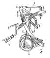
- FIG. 5is a side view of the device of FIG. 1 ;
- FIG. 6is a top view of the device in FIG. 1 .
- FIG. 5Ais a side view of the FIG. 1 apparatus showing an embodiment, where the foot pedal is essentially non-rotating between the forward and backward positions.
- FIG. 7is a right side view of the FIG. 5A and/or the FIGS. 1-6 embodiment showing the foot pedal 24 b and link or bar 28 b in their forwardmost and rearwardmost positions when the mounting member 38 for the flywheel and brake assembly, crank arms 40 a , 40 b and other associated components is positioned in a more backwardly pivoted position where axis X of mounting member 38 is in a nearly vertical orientation.
- FIG. 8is a right side view of the FIG. 5A and/or the FIGS. 1-6 embodiment showing the foot pedal 24 b and linkage bar 28 b in their forwardmost and rearwardmost positions when the mounting member 38 for the flywheel and brake assembly, crank arms 40 a , 40 b and other associated components is positioned in a more forwardly pivoted position where axis X of mounting member 38 is pivoted an angle A forwardly of the position shown in FIG. 7 .
- FIG. 9is a right side perspective view of the FIGS. 1-8 apparati having a pair of pivotable handles pivotably attached to the forward four bar linkage legs 26 a , 26 b and to the frame via a support bar 500 .
- FIG. 10is a right side view of the FIG. 9 apparatus.
- the present inventionis an exercise apparatus that provides a low impact workout yet offers the potential for an intensive cardiovascular workout by eliminating the unnatural motion and awkward foot alignments typical of many stair-climbing and elliptical training devices.
- the inventionprovides one or more foot supports movable along an arcuate path and defined around a point of rotation. The arcuate path is divisible into machine defined, user selectable arc segments.
- the exercise apparatusincludes a frame, a frame linkage movably engaged with the frame, one or more foot supports movably engaged with the frame linkage, a crank movably engaged with the frame, a motor operative to move the crank location with respect to the frame, and a drive linkage movably engaging the frame linkage.
- FIG. 1is a perspective view of an exercise device in accordance with the present invention.
- the deviceincludes a frame 10 having a front region 12 , a rear region 14 , “legs” 16 a , 16 b , 16 c and 16 d , and upper supports 18 a , 18 b , 18 c , and 18 d .
- Upper supports 18 c and 18 dcomprise the upper links of a pair of four bar linkages and part of the arcuate portion of the frame, terminate in legs 16 c and 16 b respectively and are an integral part of frame 10 .
- a display/control panel 20 and hand grips 22 a and 22 bare secured to the upper supports 18 a and 18 b.
- Foot supports 24 a and 24 bare sized to receive the foot of a user. Foot supports 24 a and 24 b are movably connected to, and supported by, forward linkages or legs 26 a and 26 b , and rear linkages 26 c and 26 d . Linkages 26 a - 26 d are movably connected to the rear region 14 of frame 10 by upper supports or links 18 d and 18 c . Although the device is shown with opposing pairs of linkages supporting each foot support, other embodiments are contemplated having fewer or more linkages supporting and controlling the range and path of motion of foot supports 24 a and 24 b associated with the linkage(s).
- the foot supports 24 a and 24 bapproximate a shod human foot in size and shape. They can include a non-skid surface and be bounded by one or more low lips to help a shoe remain in place on the foot supports during use. Alternately, straps may maintain each foot within the foot support to further retain the user's foot in place during use.
- a “foot support”can also encompass any designated support such as a pedal, a pad, a toe clip, or other foot/toe/leg and device interface structure as is known in the art.
- the forward linkages or legs 26 a and 26 bare movably connected to drive linkages 28 a and 28 b ; and the drive linkages are in turn connected to other elements (illustrated in FIGS. 3 and 4 and described below) concealed by a housing 30 .
- the drive linkages 28 a and 28 bare connected directly to the foot supports 24 a and 24 b .
- “foot supports”can be on or integral to either the forward linkages or to the one or more linkages joined to the frame.
- representative movable connectors 31 a , 31 b , 31 c , and 31 dinclude pivot assemblies, as known in the art, that provide very smooth and easy relative rotation or reciprocal motion by elements joined by the pivot assemblies.
- Movable connectors 31 b and 31 drotatably couple forward linkages or legs 26 b and 26 a , respectively, to upper supports or links 18 c and 18 d .
- Movable connectors 31 c and 31 arotatably couple rear linkages 26 c and 26 d , respectively, to upper supports or links 18 c and 18 d .
- Other connection assemblies that permit similar motionare contemplated by the invention.
- the movable connectorsallow for a smooth and controlled swinging of foot supports 24 a and 24 b in an arcuate path.
- FIG. 2is a front perspective view of the device shown in FIG. 1 illustrating the elements described above from a different angle. This illustration shows the device from the front region 12 perspective.
- foot supports 24 a and 24 bare suspended from their respective linkages.
- Drive linkages 28 a and 28 b(not shown in FIG. 2 ) are coupled at their first ends to the substantial mid-point of front linkages or legs 26 a and 26 b , respectively.
- Drive linkages 28 a and 28 bare coupled at their second ends to a crank assembly (not shown) contained within housing 30 , which contains the resistance assembly shown in FIG. 4 and described in greater detail below.
- FIG. 3is a rear view of the device of FIG. 1 .
- the illustration in FIG. 3is how a user would view the device upon mounting.
- Foot supports 24 a and 24 bare positioned to allow the user to place his or her feet on the pedals. As described above, clips or straps may be used to firmly secure the user's feet within their respective foot supports.
- Drive linkages 28 a and 28 bare coupled to either side of housing 30 .
- Crankshaft 32(shown in FIG. 4 ) projects from each side of housing 30 and is connected to each of the drive linkages via crank arms 40 a and 40 b .
- Handles 22 a and 22 ballow the user to steady themselves while the user's legs move in an arcuate path of motion.
- Monitor 20may include displays and controls to allow the user to manipulate the intensity of the resistance to create an easier or more difficult exercise routine and to adjust the motion path of the foot supports to one that is more inclined or less inclined.
- housing 30is not shown so that additional internal elements of resistance assembly 55 therein can be revealed.
- the forward ends of drive linkages 28 a and 28 bare shown attached to crank arms 40 a and 40 b , which are connected to a crankshaft 32 that turns a pulley 34 in communication with other elements described, below.
- FIG. 4illustrates the pulley 34 mounted on the crankshaft 32 .
- Top bearings 36 a and 36 b receiving the crankshaft 32are secured to a mounting 38 .
- Crank arms 40 a and 40 bare secured to each end of the crankshaft 32 and are movably coupled to the drive linkages 28 a and 28 b , respectively, as is known in the art.
- a second pulley 42rotatably mounted on stationary shaft 44 , which is mounted to frame member 38 , is coupled to the pulley 34 with a belt 50 .
- a second belt 52couples the second pulley 42 to a brake/flywheel assembly 54 , which includes a rotatable mass such as a flywheel 54 a secured to the mounting 38 .
- the mounting 38pivots around bottom bearings 46 a and 46 b so as to be rotatable fore and aft.
- a motor 56 or supplemental motor(not shown), responsive to input from the display/control panel 20 , acts as a tilt actuator to tilt the mounting 38 and the elements affixed thereto.
- the pulley 34 , the second pulley 42 and the resistance assembly 55 including a flywheel 54 arotate about an axis that is orthogonal to the longitudinal axis of the frame 10 . It should be clear from the above description of the drive system that both pedals 24 a and 24 b are synchronized together by the motion of crankshaft 32 .
- crankshaft 32 and brake/flywheel assembly 54there are no clutches between crankshaft 32 and brake/flywheel assembly 54 . This is done to allow the inertia of brake/flywheel assembly 54 within resistance assembly 55 to assist the pedals 24 a and 24 b through the weaker portion of the range of motion of the users leg.
- the brake/flywheel assembly 54is the preferred component in resistance assembly 55
- various other braking devicessuch as known to those skilled in the art can be associated with the rotatable elements to inhibit rotation thereof.
- the braking devicemay include but is not limited to any of the following: friction and air resistance devices such as fans, pneumatic or hydraulic devices, as well as various other types of electromechanical braking devices. This list is by no means exhaustive and represents only a few examples of resistance mechanisms that may be incorporated into the present invention.
- the configuration disclosed herein, i.e. use of a flywheel,is especially desirable because it promotes a very smooth, bilateral, reciprocal motion that is easily maintained by a device user.
- FIG. 5is a side view of the device.
- the foot supports 24 a and 24 b , forward linkages or legs 26 a , 26 b and rear linkages or legs 26 c , 26 dare presented from a perspective that allows ready visualization of the path that foot supports 24 a and 24 b , and thus a user's feet, will traverse as the foot supports move fore and aft while suspended from the forward and rear linkages.
- the forward and aft limit of motionis not unbounded. Rather, the range of motion is defined by the length of the crank arms 40 a and 40 b (shown in FIG.
- the foot supports 24 a and 24 bare pivotally connected to, and swing with, the forward linkages 26 a , 26 b and rear linkages 26 c , 26 d , the foot supports travel a curved or arcuate path, and not an elliptical path, to provide more favorable biomechanics.
- the motion path for the foot supports 24 a and 24 bcan also be altered by adjusting the position of mounting 38 .
- the mounting 38is pivotally mounted to the frame member 48 and pivots fore and aft upon command. As is evident by reference to the Figures, pivoting the mounting 38 forward moves the components secured directly or indirectly thereto forward. Likewise, pivoting the mounting 38 rearward causes the components secured directly or indirectly thereto to move rearward.
- This repositioningcauses the motion path of the foot supports 24 a and 24 b to move to a different location along an arcuate path around a point of rotation “p”, shown here between pivot assemblies 31 b and 31 c , at a distance established by the length of the forward and rear linkages or legs 26 a , 26 b , 26 c and 26 d .
- the specific location on the arc or arc segment(“the motion path”) is user selectable to increase or decrease stride angle and location from a number of user selectable points, or arc segments, defined around the point of rotation.
- a userIn operation, a user approaches the device from the rear region 14 , grasps the hand grips 22 a and 22 b , and places a foot on each of the foot supports 24 a and 24 b .
- the user's feet and legsbegin to move fore and aft in a comfortable stride.
- the userselects an exercise program or manually adjusts the device by imputing commands via the display/control panel 20 .
- the resistance to fore and aft movement of the foot supports 24 a and 24 bcan be altered by impeding rotation of the pulleys 34 , 42 or the flywheel.
- the mounting 38is moved fore or aft.
- the motion path of the foot supportsis on a more inclined or vertical define arc segment.
- a usersimply stops striding, thereby causing the movement of the device to stop, and dismounts from the foot supports.
- FIG. 5Aillustrates another embodiment of the invention showing one of the four bar linkage support mechanisms in a rearward 26 a ′, 26 d ′ and a forward 26 a , 26 d position along the pivot stroke of the four bar linkage.
- the four bar linkagehas opposing pivot widths (or opposing pivot link, 18 c / 24 b , 18 d / 24 a widths), W′ and W′′, and opposing pivot lengths (or opposing pivot link, 26 a / 26 d , 26 b / 26 c lengths), L′ and L′′ that form the functional four bar linkage for purposes of pivotably mounting/supporting the foot pedal 24 a from an upper portion 18 d (or foot pedal 24 b from upper portion 18 c ) of the overhead support arm or leg, 16 b , 16 c , of the frame.
- the foot pedals 24 a , 24 bthemselves comprise a structural portion or the whole of the lower pivot link of the four bar linkages in the embodiments shown in FIGS. 1-10 .
- the distances between the width pivot points 31 a and 31 d , W′ and between the width pivot points 31 e and 31 f , W′′are preferably equal or substantially equal.
- the distances between the length pivot points 31 d and 31 e , L′ and between the length pivot points 31 a and 31 f , L′′are also preferably equal or substantially equal such that the difference between angles A 1 and A 2 , i.e.
- the degree of rotation or pivot of the foot pedal 24 a from back to front and front to back along the arcuate path of translation of the foot pedal from front to back and vice versais less than about 3 degrees, typically less than about 2.5 degrees.
- the foot pedalshave a foot sole receiving upper surface that defines a generally planar orientation or plane in which the sole of the foot of the user is maintained when standing on a foot pedal.
- Angle A 1is the angle between the foot sole orientation plane PP 1 in which the foot sole surface resides at the forwardmost end of the front to back path of translation and a fixed selected reference plane RP.
- Angle A 2is the angle between the sole orientation plane PP 2 in which the foot sole surface resides at the backwardmost end of the front to back path of translation and the fixed selected reference plane RP.
- the difference between angles A 1 and A 2 , at any point/position along the back to front/front to back path of translation of the food pedal 26 ais preferably less than about 3 degrees (typically less than about 2.5 degrees), i.e. the plane in which the foot sole surface of the pedal 24 a resides does not rotate or pivot more than about 3 degrees at any time during movement through the arcuate path of translation.
- the foot pedalsalways travel in the same arcuate or other configuration of path of travel from front to rear and from rear to front.
- the overall arcuate path of travel J, FIG. 7that the pedals 24 a, b may travel in remains the same regardless of what degree of pivot the arm 38 is positioned in. Pivoting the support arm 38 to different pivot positions only changes the arc “segment” (e.g. segment AP, FIG. 7 , or segment AP′, FIG. 8 , or segment AP′′, FIG. 10 ) through which the pedals may travel from rearwardmost to forwardmost positions but does not change the overall path of arcuate travel J.
- segment APsegment e.g. segment AP, FIG. 7 , or segment AP′, FIG. 8 , or segment AP′′, FIG. 10
- the overall arcuate path of travel Jis defined by the machine or apparatus itself, i.e. by the mounting, positioning, lengths and widths of the links 18 c, d , 24 a, b and 26 a - d .
- the usermay select a segment of the overall machine defined arcuate path of foot pedal travel J depending on the degree of pivoting of arm 38 that the user selects for any given exercise session. As described below each segment selected will have a different degree of incline, e.g. H 1 for segment AP and H 2 for segment AP′.
- FIGS. 7 and 8more clearly illustrate the previously described selectability of the arc segment when the mounting member 38 and its associated control components 30 such as flywheel 54 a , brake and crank elements is/are pivoted or tilted from one orientation to another.
- the pivotable mounting member 38is positioned with its longitudinal axis X arranged in about a vertical orientation. In this orientation, the maximum difference in height or incline H 1 between the rearwardmost position 24 b ′ of the foot pedal 24 b and forwardmost position 24 b ′′ of the foot pedal 24 b is less than the maximum difference in height or incline H 2 of FIG.
- the pedalstravel along the same path AP or AP′ from front to rear and from rear to front.
- FIGS. 9 and 10show an embodiment where a pair of pivoting upper body input arms 100 a , 100 b are provided that the user can manually grasp by hand at an upper region such as handles 106 a , 106 b , the handles 106 a, b being a rigidly connected extension of arms 100 a , 100 b respectively and moving/pivoting together with the arms forward or backward.
- the handles 106 a , 106 b and arms 100 a , 100 bare pivotably interconnected to both the frame and to the pedals.
- the handles 106 a , 106 b and arms 100 a , 100 bare pivotably interconnected to the frame via a cross bar member 500 , the bottom ends of the arms being freely pivotably mounted via pin/aperture joints 104 a , 104 b at their bottom ends, the joints being attached to bar support member 500 at appropriate distances from each other along the length of bar support 500 .
- Arm linkage members 102 a , 102 bare pivotably attached at one end to the arms at joints 108 a , 108 b which allow the linkage members to rotate/pivot on and with respect to the arms.
- Linkage members 102 a , 102 bare also pivotably attached at another end to some component of the arcuate path traveling assembly of foot pedal, and four bar linkage supports 26 . As shown in FIGS. 9 , 10 an end of the linkages 102 a , 102 b distal from the arm connection point are pivotably attached to the forward longitudinal four bar linkage members 26 d , 26 a respectively via joints 110 a , 110 b that allow the linkage members to rotate around the axes of the joints, the joints interconnecting the linkage members 102 a, b and the longitudinal four bar linkage members 26 d, a.
- the handles 106 and arms 100follow the front to back movement of the pedals with a pivoting front to back or back to front movement. That is, when the right pedal 24 a moves forwardly the right handle 106 a and arm 100 a pivot or move forwardly; when the right pedal 24 a moves-backwardly the right handle 106 a and arm 100 a pivot or move rearwardly; when the left pedal 24 b moves forwardly the handle 106 b and arm 100 b pivot or move forwardly; when the left pedal 24 b moves rearwardly the handle 106 b and arm 100 b pivot or move rearwardly.
- Such following motionis shown for example with reference to four bar linkage arm 26 d in three sequential front to back positions 26 d 1 , d 2 and d 3 which correspond respectively to arm 100 a positions, 100 a 1 , a 2 , a 3 .
- the degree of front to back pivoting of the arms 100 a, bcan be predetermined at least by selective positioning of the pivot joints 108 a , 108 b , 110 a , 110 b , selective positioning of cross bar 500 and selection of the lengths of linkage arms 102 a , 102 b.
- the usercan reduce or transfer the amount of energy or power required by the user's legs and/or feet to cause the foot pedals to travel along the arcuate path AP′′ from back to front by pushing forwardly on the upper end of the arms 102 a , 102 b during the back to front pedal movement. And, the user can increase the speed of forward movement by such pushing; or reduce the speed and increase the power or energy required by the legs to effect forward movement by pulling. Conversely the user can reduce or transfer the amount of power or energy required to cause the pedals to move from front to back by pulling backwardly on the upper end of the arms. And, the user can increase the speed of rearward movement by such pulling or reduce the speed by pushing; or reduce the speed and increase the power or energy required by the legs to effect rearward movement by pushing.
- the four bar linkage foot assemblies, 24 a , 26 a, d , 18 d and 24 b , 26 c, b , 18 c that are pivotably linked via the linkages 102 a , 102 b to the pivotably mounted arms 100 a, bcan be configured to enable the foot pedal and the plane in which the sole of the foot is mounted to either not rotate or to rotate/pivot to any desired degree during front to back movement by selecting the lengths L′ and L′′ and widths W and W′, FIG. 5A appropriately to cause the desired degree of rotation/pivoting.
- These four bar linkage assembliesalso, via the above described linkages to the arms 100 a, b , cause the arms to travel along the same path of pivot from front to back and back to front.
- the linkages 28 a, a′, a′′, a ′′′ and 28 b, b′, b′′, b ′′′are interconnected to the flywheel 54 a via the four bar linkage and the linkages 28 a , 28 b at opposing 180 degree circle positions 40 c and 40 d from the center of rotation 54 b of the crank arms 40 a, b and/or flywheel 54 a , i.e. the linkages are connected at maximum forward and maximum rearward drive positions respectively.
- This 180 degree opposing interconnectioncauses the right 24 b, b′, b′′, b ′′′ and left 24 a foot pedals to always travel in opposite back and forth translational directions, i.e. when the right pedal is traveling forward the left pedal is traveling backwards and vice versa.
- the pivotably mounted arms 100 a and 100 bare interconnected to the flywheel 54 a via the four bar linkage, the links 28 a , 28 b and the links 102 a , 102 b such that when the right arm is moving forward the left arm is moving backward and vice versa.
- the arms 100 a , 100 btravel forwardly or backwardly together with their associated foot pedals 28 a and 28 b respectively.
- the left and right side pedals 24 a, b and input arms 100 a, bare linked to the resistance or drive assembly (in the embodiments shown, the flywheel and associated crank arms) such that when the left side components (i.e. left pedal and associated input arm) are traveling forward the right side components (i.e. right pedal associated input arm) are traveling backward for at least the majority of the travel path and vice versa.
- the upper body input arms 100 a, bare interconnected or interlinked to the same pivotable mounting member 38 as described above via the links 102 a, b , four bar linkage members 26 a, b and links 28 a, b as shown in FIGS. 9 , 10 .
- a forward or backward pivoting of the mounting member 38also changes the degree of back to front pivoting and/or the degree of path of travel of arms 100 a, b .
- the useris able to select the degree of incline of the path of travel of the foot pedals, e.g. arc path AP versus arc path AP′ as shown in FIGS. 7 , 8 and also described above with regard to mount member 38 enabling the user to select the degree of arc segment stride length and angle/incline, the user is able to select the degree of back to front/front to back pivot stroke or travel path of input arms, 100 a, b ; by adjusting the front to back pivot position of the center of rotation of rotation connection/interconnection points 40 c and 40 d.
- the input arms 100 a, bare linked to the foot pedals 24 a, b in a manner that causes an input arm (e.g. 100 a ) to move forwardly as its associated foot pedal ( 24 a ) moves forwardly and upwardly, or conversely that causes an input arm to move backwardly as its associated foot pedal moves backwardly and downwardly along the user selected arc segment.
- an input arme.g. 100 a
- an input arme.g. 100 a
Landscapes
- Health & Medical Sciences (AREA)
- General Health & Medical Sciences (AREA)
- Physical Education & Sports Medicine (AREA)
- Cardiology (AREA)
- Vascular Medicine (AREA)
- Life Sciences & Earth Sciences (AREA)
- Biophysics (AREA)
- Orthopedic Medicine & Surgery (AREA)
- Rehabilitation Tools (AREA)
- Cosmetics (AREA)
- Finger-Pressure Massage (AREA)
- Processing Of Meat And Fish (AREA)
Abstract
Description
Claims (14)
Priority Applications (16)
| Application Number | Priority Date | Filing Date | Title |
|---|---|---|---|
| US10/806,833US8025609B2 (en) | 2001-11-13 | 2004-03-22 | Cross trainer exercise apparatus |
| EP04030870AEP1552861B1 (en) | 2004-01-08 | 2004-12-28 | Cross training exercise apparatus |
| DK10153538.3TDK2191873T3 (en) | 2004-01-08 | 2004-12-28 | Cross-training training device |
| AT04030870TATE457785T1 (en) | 2004-01-08 | 2004-12-28 | CROSS RUNNING EXERCISE DEVICE |
| DK04030870.2TDK1552861T3 (en) | 2004-01-08 | 2004-12-28 | Elliptical cross-exercise apparatus |
| ES04030870TES2341712T3 (en) | 2004-01-08 | 2004-12-28 | CROSS TRAINING EXERCISE APPARATUS. |
| EP10153538.3AEP2191873B1 (en) | 2004-01-08 | 2004-12-28 | Cross training exercise apparatus |
| DE602004025547TDE602004025547D1 (en) | 2004-01-08 | 2004-12-28 | Cross Country exerciser |
| US11/679,211US8162805B2 (en) | 2001-11-13 | 2007-02-27 | Cross trainer exercise apparatus |
| US12/053,234US8454478B2 (en) | 2001-11-13 | 2008-03-21 | Vertical arc exercise machine |
| US12/053,254US8057363B2 (en) | 2001-11-13 | 2008-03-21 | Home ARC exercise machine |
| US12/252,629US20090042699A1 (en) | 2001-11-13 | 2008-10-16 | Cross trainer exercise apparatus |
| US12/349,593US9108081B2 (en) | 2001-11-13 | 2009-01-07 | Exercise apparatus |
| US12/709,842US20100152000A1 (en) | 2001-11-13 | 2010-02-22 | Exercise device for cross training |
| US13/033,049US8128535B2 (en) | 2001-11-13 | 2011-02-23 | Exercise device for cross training |
| US13/403,408US20120149532A1 (en) | 2001-11-13 | 2012-02-23 | Exercise device for cross training |
Applications Claiming Priority (4)
| Application Number | Priority Date | Filing Date | Title |
|---|---|---|---|
| US33749801P | 2001-11-13 | 2001-11-13 | |
| US10/294,017US20030092532A1 (en) | 2001-11-13 | 2002-11-13 | Exercise device for cross training |
| US53490404P | 2004-01-08 | 2004-01-08 | |
| US10/806,833US8025609B2 (en) | 2001-11-13 | 2004-03-22 | Cross trainer exercise apparatus |
Related Parent Applications (4)
| Application Number | Title | Priority Date | Filing Date |
|---|---|---|---|
| US10/294,017Continuation-In-PartUS20030092532A1 (en) | 2001-11-13 | 2002-11-13 | Exercise device for cross training |
| US29/276,253Continuation-In-PartUSD563489S1 (en) | 2001-11-13 | 2007-01-19 | Arc trainer |
| US29/276,249Continuation-In-PartUSD564051S1 (en) | 2001-11-13 | 2007-01-19 | Vertical arc trainer |
| US12/053,254Continuation-In-PartUS8057363B2 (en) | 2001-11-13 | 2008-03-21 | Home ARC exercise machine |
Related Child Applications (7)
| Application Number | Title | Priority Date | Filing Date |
|---|---|---|---|
| US10/294,017ContinuationUS20030092532A1 (en) | 2001-11-13 | 2002-11-13 | Exercise device for cross training |
| US10/294,017Continuation-In-PartUS20030092532A1 (en) | 2001-11-13 | 2002-11-13 | Exercise device for cross training |
| US29/276,249Continuation-In-PartUSD564051S1 (en) | 2001-11-13 | 2007-01-19 | Vertical arc trainer |
| US11/679,211ContinuationUS8162805B2 (en) | 2001-11-13 | 2007-02-27 | Cross trainer exercise apparatus |
| US11/679,211DivisionUS8162805B2 (en) | 2001-11-13 | 2007-02-27 | Cross trainer exercise apparatus |
| US12/252,629ContinuationUS20090042699A1 (en) | 2001-11-13 | 2008-10-16 | Cross trainer exercise apparatus |
| US13/033,049ContinuationUS8128535B2 (en) | 2001-11-13 | 2011-02-23 | Exercise device for cross training |
Publications (2)
| Publication Number | Publication Date |
|---|---|
| US20040224825A1 US20040224825A1 (en) | 2004-11-11 |
| US8025609B2true US8025609B2 (en) | 2011-09-27 |
Family
ID=34595339
Family Applications (3)
| Application Number | Title | Priority Date | Filing Date |
|---|---|---|---|
| US10/806,833Expired - LifetimeUS8025609B2 (en) | 2001-11-13 | 2004-03-22 | Cross trainer exercise apparatus |
| US11/679,211Expired - Fee RelatedUS8162805B2 (en) | 2001-11-13 | 2007-02-27 | Cross trainer exercise apparatus |
| US12/252,629AbandonedUS20090042699A1 (en) | 2001-11-13 | 2008-10-16 | Cross trainer exercise apparatus |
Family Applications After (2)
| Application Number | Title | Priority Date | Filing Date |
|---|---|---|---|
| US11/679,211Expired - Fee RelatedUS8162805B2 (en) | 2001-11-13 | 2007-02-27 | Cross trainer exercise apparatus |
| US12/252,629AbandonedUS20090042699A1 (en) | 2001-11-13 | 2008-10-16 | Cross trainer exercise apparatus |
Country Status (6)
| Country | Link |
|---|---|
| US (3) | US8025609B2 (en) |
| EP (2) | EP2191873B1 (en) |
| AT (1) | ATE457785T1 (en) |
| DE (1) | DE602004025547D1 (en) |
| DK (2) | DK1552861T3 (en) |
| ES (1) | ES2341712T3 (en) |
Cited By (23)
| Publication number | Priority date | Publication date | Assignee | Title |
|---|---|---|---|---|
| US8734299B2 (en) | 2003-02-28 | 2014-05-27 | Nautilus, Inc. | Upper body exercise and flywheel enhanced dual deck treadmills |
| WO2015038732A1 (en)* | 2013-09-11 | 2015-03-19 | Cybex International, Inc. | Exercise apparatus |
| WO2015138550A1 (en) | 2014-03-11 | 2015-09-17 | Cybex International, Inc. | Abdominal exercise apparatus |
| US9352187B2 (en) | 2003-02-28 | 2016-05-31 | Nautilus, Inc. | Dual deck exercise device |
| US9440107B2 (en) | 2003-02-28 | 2016-09-13 | Nautilus, Inc. | Exercise device with treadles |
| WO2017014805A1 (en) | 2015-07-17 | 2017-01-26 | Cybex International, Inc. | Stair climbing apparatus and method |
| US20180339188A1 (en)* | 2014-11-11 | 2018-11-29 | Cybex International, Inc. | Exercise apparatus |
| US10279212B2 (en) | 2013-03-14 | 2019-05-07 | Icon Health & Fitness, Inc. | Strength training apparatus with flywheel and related methods |
| US10493349B2 (en) | 2016-03-18 | 2019-12-03 | Icon Health & Fitness, Inc. | Display on exercise device |
| US10500473B2 (en) | 2016-10-10 | 2019-12-10 | Icon Health & Fitness, Inc. | Console positioning |
| US10561894B2 (en) | 2016-03-18 | 2020-02-18 | Icon Health & Fitness, Inc. | Treadmill with removable supports |
| US10625114B2 (en) | 2016-11-01 | 2020-04-21 | Icon Health & Fitness, Inc. | Elliptical and stationary bicycle apparatus including row functionality |
| US10625137B2 (en) | 2016-03-18 | 2020-04-21 | Icon Health & Fitness, Inc. | Coordinated displays in an exercise device |
| US10653914B2 (en) | 2015-08-31 | 2020-05-19 | Product Design Innovations, Llc | Upper and lower body push and pull exercise machine with a one directional resistance mechanism and adjustable angle |
| US10661116B2 (en) | 2014-03-11 | 2020-05-26 | Cybex International, Inc. | Back extension exercise apparatus |
| US10661114B2 (en) | 2016-11-01 | 2020-05-26 | Icon Health & Fitness, Inc. | Body weight lift mechanism on treadmill |
| US10729965B2 (en) | 2017-12-22 | 2020-08-04 | Icon Health & Fitness, Inc. | Audible belt guide in a treadmill |
| US10780314B2 (en) | 2016-03-25 | 2020-09-22 | Cybex International, Inc. | Exercise apparatus |
| US10953305B2 (en) | 2015-08-26 | 2021-03-23 | Icon Health & Fitness, Inc. | Strength exercise mechanisms |
| US11524206B2 (en) | 2015-08-31 | 2022-12-13 | Joseph K. Ellis | Upper and lower body push and pull exercise machine with a one directional resistance mechanism and adjustable angle |
| US11794066B2 (en) | 2015-08-31 | 2023-10-24 | Joseph K. Ellis | Upper and lower body reciprocating arcing motion exercise machine with an adjustable angle user support |
| US12194335B2 (en) | 2022-10-17 | 2025-01-14 | Joseph K. Ellis | Crawl simulation exercise and stretching machine |
| US12330019B2 (en) | 2015-08-31 | 2025-06-17 | Product Design Innovations, Llc | Upper and lower body reciprocating arcing motion exercise machine with an adjustable angle user support |
Families Citing this family (55)
| Publication number | Priority date | Publication date | Assignee | Title |
|---|---|---|---|---|
| CA2411657C (en)* | 2001-11-13 | 2009-05-19 | Cybex International, Inc. | Exercise device for cross training |
| US8025609B2 (en)* | 2001-11-13 | 2011-09-27 | Cybex International, Inc. | Cross trainer exercise apparatus |
| US7169087B2 (en)* | 2003-02-19 | 2007-01-30 | Icon Health & Fitness, Inc. | Cushioned elliptical exerciser |
| US7530926B2 (en)* | 2003-12-04 | 2009-05-12 | Rodgers Jr Robert E | Pendulum striding exercise devices |
| US7520839B2 (en)* | 2003-12-04 | 2009-04-21 | Rodgers Jr Robert E | Pendulum striding exercise apparatus |
| US7740563B2 (en) | 2004-08-11 | 2010-06-22 | Icon Ip, Inc. | Elliptical exercise machine with integrated anaerobic exercise system |
| US7766797B2 (en) | 2004-08-11 | 2010-08-03 | Icon Ip, Inc. | Breakaway or folding elliptical exercise machine |
| US7780577B2 (en)* | 2006-07-14 | 2010-08-24 | Precor Incorporated | Pendulous exercise device |
| US20080020905A1 (en)* | 2006-07-24 | 2008-01-24 | Dream Visions, Llc | Adjustable foot support platform for an exercise apparatus |
| US7658698B2 (en) | 2006-08-02 | 2010-02-09 | Icon Ip, Inc. | Variable stride exercise device with ramp |
| US7717828B2 (en) | 2006-08-02 | 2010-05-18 | Icon Ip, Inc. | Exercise device with pivoting assembly |
| US8109861B2 (en)* | 2006-08-10 | 2012-02-07 | Exerciting, Llc | Exercise device with varied gait movements |
| USD559925S1 (en) | 2006-12-28 | 2008-01-15 | Precor Incorporated | Exercise device |
| US9011291B2 (en) | 2011-04-14 | 2015-04-21 | Precor Incorporated | Exercise device path traces |
| USD575363S1 (en) | 2006-12-28 | 2008-08-19 | Precor Incorporated | Foot pad for an exercise device |
| USD567313S1 (en) | 2006-12-28 | 2008-04-22 | Precor Incorporated | Linkage member for an exercise device |
| USD570430S1 (en) | 2006-12-28 | 2008-06-03 | Precor Incorporated | Linkage for an exercise device |
| US7736279B2 (en) | 2007-02-20 | 2010-06-15 | Icon Ip, Inc. | One-step foldable elliptical exercise machine |
| US20080269022A1 (en)* | 2007-04-27 | 2008-10-30 | Sunny Lee | Exercising machine with adjustable stride length and height |
| US7674205B2 (en) | 2007-05-08 | 2010-03-09 | Icon Ip, Inc. | Elliptical exercise machine with adjustable foot motion |
| US7618350B2 (en) | 2007-06-04 | 2009-11-17 | Icon Ip, Inc. | Elliptical exercise machine with adjustable ramp |
| US8043997B2 (en)* | 2008-02-29 | 2011-10-25 | Halliburton Energy Services Inc. | Lost circulation material formulation and method of use |
| US8033961B2 (en)* | 2008-10-15 | 2011-10-11 | Sports Art Industrial Co., Ltd. | Athletic apparatus with non-linear sliding track |
| US7922625B2 (en)* | 2008-12-29 | 2011-04-12 | Precor Incorporated | Adaptive motion exercise device with oscillating track |
| US8556779B2 (en) | 2008-12-29 | 2013-10-15 | Precor Incorporated | Exercise device with gliding footlink pivot guide |
| US7874963B2 (en)* | 2008-12-29 | 2011-01-25 | Precor Incorporated | Exercise device with adaptive curved track motion |
| US7887465B2 (en)* | 2009-02-06 | 2011-02-15 | Precor Incorporated | Adaptive motion exercise device with plural crank assemblies |
| US8740754B2 (en)* | 2010-01-11 | 2014-06-03 | Larry D. Miller | Adaptive exercise device |
| US9597540B2 (en) | 2012-02-14 | 2017-03-21 | Precor Incorporated | Adaptive motion exercise device |
| CA2860427C (en)* | 2013-08-29 | 2020-02-25 | Octane Fitness, Llc | Lower body mimetic exercise device with fully or partially autonomous right and left leg links and ergonomically positioned pivot points |
| CA2924350A1 (en)* | 2013-09-18 | 2015-03-26 | Cybex International, Inc. | Adaptive resistance exerting exercise apparatus |
| WO2015100429A1 (en) | 2013-12-26 | 2015-07-02 | Icon Health & Fitness, Inc. | Magnetic resistance mechanism in a cable machine |
| US10433612B2 (en) | 2014-03-10 | 2019-10-08 | Icon Health & Fitness, Inc. | Pressure sensor to quantify work |
| CN106470739B (en) | 2014-06-09 | 2019-06-21 | 爱康保健健身有限公司 | Cable system incorporated into the treadmill |
| WO2016076836A1 (en)* | 2014-11-11 | 2016-05-19 | Cybex International, Inc. | Exercise apparatus |
| US9295874B1 (en)* | 2014-11-24 | 2016-03-29 | Yi-Tzu Chen | Elliptical trainer |
| US9682277B2 (en) | 2014-12-10 | 2017-06-20 | Fit-Novation, Inc. | Exercise device |
| US10258828B2 (en) | 2015-01-16 | 2019-04-16 | Icon Health & Fitness, Inc. | Controls for an exercise device |
| CN105983207B (en)* | 2015-02-16 | 2019-01-04 | 光昱金属有限公司 | Swinging sports equipment and adjusting method thereof |
| US10046197B2 (en) | 2015-11-19 | 2018-08-14 | Fitnovation, Inc. | Exercise device |
| US10293211B2 (en) | 2016-03-18 | 2019-05-21 | Icon Health & Fitness, Inc. | Coordinated weight selection |
| US10272317B2 (en) | 2016-03-18 | 2019-04-30 | Icon Health & Fitness, Inc. | Lighted pace feature in a treadmill |
| DE102017003859A1 (en) | 2016-04-21 | 2017-10-26 | Martin Kraiss | Indoortrainer with arm and leg drive |
| US10252109B2 (en) | 2016-05-13 | 2019-04-09 | Icon Health & Fitness, Inc. | Weight platform treadmill |
| US10471299B2 (en) | 2016-07-01 | 2019-11-12 | Icon Health & Fitness, Inc. | Systems and methods for cooling internal exercise equipment components |
| US10441844B2 (en) | 2016-07-01 | 2019-10-15 | Icon Health & Fitness, Inc. | Cooling systems and methods for exercise equipment |
| US10376736B2 (en) | 2016-10-12 | 2019-08-13 | Icon Health & Fitness, Inc. | Cooling an exercise device during a dive motor runway condition |
| TWI646997B (en) | 2016-11-01 | 2019-01-11 | 美商愛康運動與健康公司 | Distance sensor for console positioning |
| TWI680782B (en) | 2016-12-05 | 2020-01-01 | 美商愛康運動與健康公司 | Offsetting treadmill deck weight during operation |
| CN107174486A (en)* | 2017-07-17 | 2017-09-19 | 衢州学院 | The full-automatic four limbs rehabilitation trainer of clutch luffing type |
| TWI756672B (en) | 2017-08-16 | 2022-03-01 | 美商愛康有限公司 | System for opposing axial impact loading in a motor |
| CA3038734A1 (en)* | 2018-04-05 | 2019-10-05 | British Columbia Institute Of Technology | Active arm passive leg exercise machine with guided leg movement |
| EP4034266B1 (en) | 2019-09-27 | 2025-08-13 | Kompan A/S | Multi-functional training apparatus |
| US11883714B2 (en)* | 2020-12-24 | 2024-01-30 | ALT Innovations LLC | Upper body gait ergometer and gait trainer |
| CN114288617B (en)* | 2022-01-12 | 2023-10-31 | 重庆医科大学 | Exercise device for rehabilitation training |
Citations (67)
| Publication number | Priority date | Publication date | Assignee | Title |
|---|---|---|---|---|
| DE229712C (en) | ||||
| US326247A (en)* | 1885-02-16 | 1885-09-15 | Exercising-machine | |
| FR498150A (en) | 1916-06-06 | 1919-12-30 | Pierre Joseph Amieux | Mechanotherapy device intended for the passive mobilization of the lower limbs of injured or bedridden patients |
| US1990124A (en) | 1927-02-12 | 1935-02-05 | Charles W Kabisius | Mechanical crawl stroke swimming instructor |
| US2019224A (en) | 1933-02-10 | 1935-10-29 | Hess Erhard | Swimming practice apparatus |
| US2109775A (en) | 1932-05-09 | 1938-03-01 | Jesse B Hudson | Apparatus for teaching swimming |
| US3756595A (en) | 1971-04-23 | 1973-09-04 | G Hague | Leg exercising device for simulating ice skating |
| US3791646A (en) | 1970-09-30 | 1974-02-12 | A Marchignoni | Exercising and teaching apparatus for limb training and for teaching swimming |
| US4861023A (en) | 1987-07-31 | 1989-08-29 | Mike Wedman | Leg muscle exercise device and method |
| CH673092A5 (en) | 1987-07-21 | 1990-02-15 | Baechler Anton R | Training device for winter sports - has roller mounted foot supports incorporating free wheels permitting sideways swing in alternate directions |
| US5004224A (en)* | 1990-06-01 | 1991-04-02 | Teresa Wang | Stepping exerciser |
| US5039088A (en)* | 1990-04-26 | 1991-08-13 | Shifferaw Tessema D | Exercise machine |
| US5242343A (en) | 1992-09-30 | 1993-09-07 | Larry Miller | Stationary exercise device |
| US5279529A (en) | 1992-04-16 | 1994-01-18 | Eschenbach Paul W | Programmed pedal platform exercise apparatus |
| WO1995000209A1 (en) | 1993-06-18 | 1995-01-05 | Pacific Fitness Corporation | Recumbent leg exerciser |
| US5391130A (en) | 1989-02-03 | 1995-02-21 | Green; Edward J. | Leg exerciser |
| US5496235A (en)* | 1995-08-04 | 1996-03-05 | Stevens; Clive G. | Walking exeriser |
| WO1996008292A1 (en) | 1994-09-16 | 1996-03-21 | Patrick Henri Ulrich | Walking exerciser |
| US5562574A (en) | 1996-02-08 | 1996-10-08 | Miller; Larry | Compact exercise device |
| US5584781A (en)* | 1996-04-29 | 1996-12-17 | Chen; Paul | Striding exerciser |
| US5605521A (en)* | 1996-02-15 | 1997-02-25 | Lifegear, Inc. | Striding exerciser |
| US5643153A (en) | 1993-01-27 | 1997-07-01 | Nordic Track, Inc. | Flywheel resistance mechanism for exercise equipment |
| US5655998A (en)* | 1996-12-03 | 1997-08-12 | Yu; Chih-An | Space walking exerciser |
| US5685804A (en) | 1995-12-07 | 1997-11-11 | Precor Incorporated | Stationary exercise device |
| US5707320A (en) | 1996-12-18 | 1998-01-13 | Yu; Huei-Nan | Swimming exerciser |
| US5720698A (en) | 1996-05-06 | 1998-02-24 | Icon Health & Fitness, Inc. | Striding exerciser |
| US5788610A (en) | 1996-09-09 | 1998-08-04 | Eschenbach; Paul William | Elliptical exercise machine with arm exercise |
| US5792027A (en) | 1997-01-09 | 1998-08-11 | Kordun, Ltd. | Aerobic striding exerciser |
| US5833584A (en) | 1993-09-30 | 1998-11-10 | Fitness Master, Inc. | Striding exerciser with upwardly curved tracks |
| US5857940A (en)* | 1995-12-14 | 1999-01-12 | Husted; Royce H. | Low impact simulated striding device |
| US5876307A (en) | 1997-04-04 | 1999-03-02 | Stearns; Kenneth W. | Elliptical motion exercise apparatus |
| US5879271A (en) | 1997-04-15 | 1999-03-09 | Stearns; Kenneth W. | Exercise method and apparatus |
| US5895339A (en) | 1995-06-30 | 1999-04-20 | Maresh; Joseph D. | Elliptical exercise methods and apparatus |
| US5897459A (en) | 1990-06-21 | 1999-04-27 | Tnwk Corporation | Recumbent leg exerciser |
| US5910072A (en) | 1997-12-03 | 1999-06-08 | Stairmaster Sports/Medical Products, Inc. | Exercise apparatus |
| US5913751A (en) | 1997-10-09 | 1999-06-22 | Eschenbach; Paul William | Walker exercise apparatus with arm exercise |
| US5916064A (en) | 1997-11-10 | 1999-06-29 | Eschenbach; Paul William | Compact exercise apparatus |
| US5921894A (en) | 1997-10-21 | 1999-07-13 | Eschenbach; Paul William | Compact elliptical exercise apparatus |
| US5957814A (en) | 1997-06-09 | 1999-09-28 | Eschenbach; Paul William | Orbital exercise apparatus with arm exercise |
| US5993359A (en) | 1997-10-21 | 1999-11-30 | Eschenbach; Paul William | Variable stroke elliptical exercise apparatus |
| US6004244A (en) | 1997-02-13 | 1999-12-21 | Cybex International, Inc. | Simulated hill-climbing exercise apparatus and method of exercising |
| US6022296A (en)* | 1999-07-21 | 2000-02-08 | Yu; Hui-Nan | Stepping exerciser |
| US6024676A (en) | 1997-06-09 | 2000-02-15 | Eschenbach; Paul William | Compact cross trainer exercise apparatus |
| US6027430A (en) | 1997-03-31 | 2000-02-22 | Stearns; Kenneth W. | Exercise methods and apparatus |
| US6036622A (en)* | 1997-10-10 | 2000-03-14 | Gordon; Joel D. | Exercise device |
| US6042512A (en) | 1999-07-27 | 2000-03-28 | Eschenbach; Paul William | Variable lift cross trainer exercise apparatus |
| US6045488A (en) | 1999-08-11 | 2000-04-04 | Eschenbach; Paul William | Lift variable cross trainer exercise apparatus |
| US6053847A (en) | 1997-05-05 | 2000-04-25 | Stearns; Kenneth W. | Elliptical exercise method and apparatus |
| US6077196A (en) | 1999-10-01 | 2000-06-20 | Eschenbach; Paul William | Adjustable elliptical exercise apparatus |
| US6077198A (en) | 1999-08-30 | 2000-06-20 | Eschenbach; Paul William | Selective lift cross trainer exercise apparatus |
| US6090014A (en) | 1999-08-09 | 2000-07-18 | Eschenbach; Paul William | Adjustable cross trainer exercise apparatus |
| US6090013A (en) | 1998-12-07 | 2000-07-18 | Eschenbach; Paul William | Cross trainer exercise apparatus |
| US6126573A (en) | 1996-03-07 | 2000-10-03 | Eschenbach; Paul William | Stand-up exercise machine with arm exercise |
| US6135926A (en) | 1997-05-27 | 2000-10-24 | Lee; Gin Wen | Striding exerciser |
| US6142915A (en) | 1996-09-09 | 2000-11-07 | Eschenbach; Paul William | Standup exercise apparatus with pedal articulation |
| US6168552B1 (en) | 1992-11-04 | 2001-01-02 | Paul William Eschenbach | Selective lift elliptical exercise apparatus |
| US6210305B1 (en) | 1999-07-27 | 2001-04-03 | Paul William Eschenbach | Variable lift exercise apparatus with curved guide |
| US6248044B1 (en) | 1997-08-19 | 2001-06-19 | Kenneth W. Stearns | Elliptical exercise methods and apparatus |
| US6277054B1 (en) | 2000-07-17 | 2001-08-21 | Hai Pin Kuo | Exerciser having adjustable mechanism |
| USD450101S1 (en) | 2000-10-05 | 2001-11-06 | Hank Hsu | Housing of exercise machine |
| US6361476B1 (en) | 1999-07-27 | 2002-03-26 | Paul William Eschenbach | Variable stride elliptical exercise apparatus |
| US6551218B2 (en) | 1999-04-26 | 2003-04-22 | Unisen, Inc. | Deep stride exercise machine |
| US20030092532A1 (en) | 2001-11-13 | 2003-05-15 | Cybex International, Inc. | Exercise device for cross training |
| US6648801B2 (en) | 1998-04-22 | 2003-11-18 | Kenneth W. Stearns | Exercise apparatus with elliptical foot motion |
| CA2407758A1 (en) | 2002-10-11 | 2004-04-11 | Nash Nizamuddin | Exercise apparatus for simulating skating movement |
| US6761665B2 (en)* | 2001-03-01 | 2004-07-13 | Hieu Trong Nguyen | Multi-function exercise apparatus |
| US20040224825A1 (en) | 2001-11-13 | 2004-11-11 | Cybex International, Inc. | Cross trainer exercise apparatus |
Family Cites Families (5)
| Publication number | Priority date | Publication date | Assignee | Title |
|---|---|---|---|---|
| US5290211A (en)* | 1992-10-29 | 1994-03-01 | Stearns Technologies, Inc. | Exercise device |
| US7530926B2 (en)* | 2003-12-04 | 2009-05-12 | Rodgers Jr Robert E | Pendulum striding exercise devices |
| US7520839B2 (en)* | 2003-12-04 | 2009-04-21 | Rodgers Jr Robert E | Pendulum striding exercise apparatus |
| US20060116247A1 (en)* | 2004-12-01 | 2006-06-01 | Precor, Inc. | Total body elliptical exercise equipment with upper body monitoring |
| US7731634B2 (en)* | 2005-02-09 | 2010-06-08 | Precor Incorporated | Elliptical exercise equipment with stowable arms |
- 2004
- 2004-03-22USUS10/806,833patent/US8025609B2/ennot_activeExpired - Lifetime
- 2004-12-28ATAT04030870Tpatent/ATE457785T1/ennot_activeIP Right Cessation
- 2004-12-28DKDK04030870.2Tpatent/DK1552861T3/enactive
- 2004-12-28ESES04030870Tpatent/ES2341712T3/ennot_activeExpired - Lifetime
- 2004-12-28EPEP10153538.3Apatent/EP2191873B1/ennot_activeExpired - Lifetime
- 2004-12-28DKDK10153538.3Tpatent/DK2191873T3/enactive
- 2004-12-28DEDE602004025547Tpatent/DE602004025547D1/ennot_activeExpired - Lifetime
- 2004-12-28EPEP04030870Apatent/EP1552861B1/ennot_activeExpired - Lifetime
- 2007
- 2007-02-27USUS11/679,211patent/US8162805B2/ennot_activeExpired - Fee Related
- 2008
- 2008-10-16USUS12/252,629patent/US20090042699A1/ennot_activeAbandoned
Patent Citations (71)
| Publication number | Priority date | Publication date | Assignee | Title |
|---|---|---|---|---|
| DE229712C (en) | ||||
| US326247A (en)* | 1885-02-16 | 1885-09-15 | Exercising-machine | |
| FR498150A (en) | 1916-06-06 | 1919-12-30 | Pierre Joseph Amieux | Mechanotherapy device intended for the passive mobilization of the lower limbs of injured or bedridden patients |
| US1990124A (en) | 1927-02-12 | 1935-02-05 | Charles W Kabisius | Mechanical crawl stroke swimming instructor |
| US2109775A (en) | 1932-05-09 | 1938-03-01 | Jesse B Hudson | Apparatus for teaching swimming |
| US2019224A (en) | 1933-02-10 | 1935-10-29 | Hess Erhard | Swimming practice apparatus |
| US3791646A (en) | 1970-09-30 | 1974-02-12 | A Marchignoni | Exercising and teaching apparatus for limb training and for teaching swimming |
| US3756595A (en) | 1971-04-23 | 1973-09-04 | G Hague | Leg exercising device for simulating ice skating |
| CH673092A5 (en) | 1987-07-21 | 1990-02-15 | Baechler Anton R | Training device for winter sports - has roller mounted foot supports incorporating free wheels permitting sideways swing in alternate directions |
| US4861023A (en) | 1987-07-31 | 1989-08-29 | Mike Wedman | Leg muscle exercise device and method |
| US5391130A (en) | 1989-02-03 | 1995-02-21 | Green; Edward J. | Leg exerciser |
| US5039088A (en)* | 1990-04-26 | 1991-08-13 | Shifferaw Tessema D | Exercise machine |
| US5004224A (en)* | 1990-06-01 | 1991-04-02 | Teresa Wang | Stepping exerciser |
| US5897459A (en) | 1990-06-21 | 1999-04-27 | Tnwk Corporation | Recumbent leg exerciser |
| US5279529A (en) | 1992-04-16 | 1994-01-18 | Eschenbach Paul W | Programmed pedal platform exercise apparatus |
| US5383829A (en) | 1992-09-30 | 1995-01-24 | Miller; Larry | Stationary exercise device |
| US5242343A (en) | 1992-09-30 | 1993-09-07 | Larry Miller | Stationary exercise device |
| US5383829C1 (en) | 1992-09-30 | 2002-03-05 | Larry Miller | Stationary exercise device |
| US6168552B1 (en) | 1992-11-04 | 2001-01-02 | Paul William Eschenbach | Selective lift elliptical exercise apparatus |
| US5643153A (en) | 1993-01-27 | 1997-07-01 | Nordic Track, Inc. | Flywheel resistance mechanism for exercise equipment |
| WO1995000209A1 (en) | 1993-06-18 | 1995-01-05 | Pacific Fitness Corporation | Recumbent leg exerciser |
| US5833584A (en) | 1993-09-30 | 1998-11-10 | Fitness Master, Inc. | Striding exerciser with upwardly curved tracks |
| WO1996008292A1 (en) | 1994-09-16 | 1996-03-21 | Patrick Henri Ulrich | Walking exerciser |
| US5895339A (en) | 1995-06-30 | 1999-04-20 | Maresh; Joseph D. | Elliptical exercise methods and apparatus |
| US6217485B1 (en) | 1995-06-30 | 2001-04-17 | Joseph D. Maresh | Elliptical exercise methods and apparatus |
| US5496235A (en)* | 1995-08-04 | 1996-03-05 | Stevens; Clive G. | Walking exeriser |
| US5685804A (en) | 1995-12-07 | 1997-11-11 | Precor Incorporated | Stationary exercise device |
| US5857940A (en)* | 1995-12-14 | 1999-01-12 | Husted; Royce H. | Low impact simulated striding device |
| US5562574A (en) | 1996-02-08 | 1996-10-08 | Miller; Larry | Compact exercise device |
| US5605521A (en)* | 1996-02-15 | 1997-02-25 | Lifegear, Inc. | Striding exerciser |
| US5681244A (en) | 1996-02-15 | 1997-10-28 | Lifegear, Inc. | Striding exerciser |
| US6126573A (en) | 1996-03-07 | 2000-10-03 | Eschenbach; Paul William | Stand-up exercise machine with arm exercise |
| US5584781A (en)* | 1996-04-29 | 1996-12-17 | Chen; Paul | Striding exerciser |
| US5720698A (en) | 1996-05-06 | 1998-02-24 | Icon Health & Fitness, Inc. | Striding exerciser |
| US6142915A (en) | 1996-09-09 | 2000-11-07 | Eschenbach; Paul William | Standup exercise apparatus with pedal articulation |
| US5788610A (en) | 1996-09-09 | 1998-08-04 | Eschenbach; Paul William | Elliptical exercise machine with arm exercise |
| US5655998A (en)* | 1996-12-03 | 1997-08-12 | Yu; Chih-An | Space walking exerciser |
| US5707320A (en) | 1996-12-18 | 1998-01-13 | Yu; Huei-Nan | Swimming exerciser |
| US5792027A (en) | 1997-01-09 | 1998-08-11 | Kordun, Ltd. | Aerobic striding exerciser |
| US6004244A (en) | 1997-02-13 | 1999-12-21 | Cybex International, Inc. | Simulated hill-climbing exercise apparatus and method of exercising |
| US6027430A (en) | 1997-03-31 | 2000-02-22 | Stearns; Kenneth W. | Exercise methods and apparatus |
| US5876307A (en) | 1997-04-04 | 1999-03-02 | Stearns; Kenneth W. | Elliptical motion exercise apparatus |
| US5879271A (en) | 1997-04-15 | 1999-03-09 | Stearns; Kenneth W. | Exercise method and apparatus |
| US6053847A (en) | 1997-05-05 | 2000-04-25 | Stearns; Kenneth W. | Elliptical exercise method and apparatus |
| US6135926A (en) | 1997-05-27 | 2000-10-24 | Lee; Gin Wen | Striding exerciser |
| US5957814A (en) | 1997-06-09 | 1999-09-28 | Eschenbach; Paul William | Orbital exercise apparatus with arm exercise |
| US6024676A (en) | 1997-06-09 | 2000-02-15 | Eschenbach; Paul William | Compact cross trainer exercise apparatus |
| US6248044B1 (en) | 1997-08-19 | 2001-06-19 | Kenneth W. Stearns | Elliptical exercise methods and apparatus |
| US5913751A (en) | 1997-10-09 | 1999-06-22 | Eschenbach; Paul William | Walker exercise apparatus with arm exercise |
| US6036622A (en)* | 1997-10-10 | 2000-03-14 | Gordon; Joel D. | Exercise device |
| US5993359A (en) | 1997-10-21 | 1999-11-30 | Eschenbach; Paul William | Variable stroke elliptical exercise apparatus |
| US5921894A (en) | 1997-10-21 | 1999-07-13 | Eschenbach; Paul William | Compact elliptical exercise apparatus |
| US5916064A (en) | 1997-11-10 | 1999-06-29 | Eschenbach; Paul William | Compact exercise apparatus |
| US5910072A (en) | 1997-12-03 | 1999-06-08 | Stairmaster Sports/Medical Products, Inc. | Exercise apparatus |
| US6648801B2 (en) | 1998-04-22 | 2003-11-18 | Kenneth W. Stearns | Exercise apparatus with elliptical foot motion |
| US6090013A (en) | 1998-12-07 | 2000-07-18 | Eschenbach; Paul William | Cross trainer exercise apparatus |
| US6551218B2 (en) | 1999-04-26 | 2003-04-22 | Unisen, Inc. | Deep stride exercise machine |
| US6022296A (en)* | 1999-07-21 | 2000-02-08 | Yu; Hui-Nan | Stepping exerciser |
| US6361476B1 (en) | 1999-07-27 | 2002-03-26 | Paul William Eschenbach | Variable stride elliptical exercise apparatus |
| US6042512A (en) | 1999-07-27 | 2000-03-28 | Eschenbach; Paul William | Variable lift cross trainer exercise apparatus |
| US6210305B1 (en) | 1999-07-27 | 2001-04-03 | Paul William Eschenbach | Variable lift exercise apparatus with curved guide |
| US6090014A (en) | 1999-08-09 | 2000-07-18 | Eschenbach; Paul William | Adjustable cross trainer exercise apparatus |
| US6045488A (en) | 1999-08-11 | 2000-04-04 | Eschenbach; Paul William | Lift variable cross trainer exercise apparatus |
| US6077198A (en) | 1999-08-30 | 2000-06-20 | Eschenbach; Paul William | Selective lift cross trainer exercise apparatus |
| US6077196A (en) | 1999-10-01 | 2000-06-20 | Eschenbach; Paul William | Adjustable elliptical exercise apparatus |
| US6277054B1 (en) | 2000-07-17 | 2001-08-21 | Hai Pin Kuo | Exerciser having adjustable mechanism |
| USD450101S1 (en) | 2000-10-05 | 2001-11-06 | Hank Hsu | Housing of exercise machine |
| US6761665B2 (en)* | 2001-03-01 | 2004-07-13 | Hieu Trong Nguyen | Multi-function exercise apparatus |
| US20030092532A1 (en) | 2001-11-13 | 2003-05-15 | Cybex International, Inc. | Exercise device for cross training |
| US20040224825A1 (en) | 2001-11-13 | 2004-11-11 | Cybex International, Inc. | Cross trainer exercise apparatus |
| CA2407758A1 (en) | 2002-10-11 | 2004-04-11 | Nash Nizamuddin | Exercise apparatus for simulating skating movement |
Non-Patent Citations (2)
| Title |
|---|
| Dr. Theodor Büdingen in Konstanz "Bewegungsapparat für Bettlägerige, insbesondere Herzkranke" Oct. 20, 1908. |
| M. Pierre-Joseph Amieux, rèsident en France (Hautes-Alpes) "Appareil mècanothèrapique destine á la mobilisation passive des membres infèrieurs des blessès ou malades alitès" Jun. 6, 1916. |
Cited By (49)
| Publication number | Priority date | Publication date | Assignee | Title |
|---|---|---|---|---|
| US9308415B2 (en) | 2003-02-28 | 2016-04-12 | Nautilus, Inc. | Upper body exercise and flywheel enhanced dual deck treadmills |
| US8734299B2 (en) | 2003-02-28 | 2014-05-27 | Nautilus, Inc. | Upper body exercise and flywheel enhanced dual deck treadmills |
| US9440107B2 (en) | 2003-02-28 | 2016-09-13 | Nautilus, Inc. | Exercise device with treadles |
| US9352187B2 (en) | 2003-02-28 | 2016-05-31 | Nautilus, Inc. | Dual deck exercise device |
| US10279212B2 (en) | 2013-03-14 | 2019-05-07 | Icon Health & Fitness, Inc. | Strength training apparatus with flywheel and related methods |
| US10105569B2 (en) | 2013-09-11 | 2018-10-23 | Cybex International, Inc. | Exercise apparatus |
| US9144705B1 (en) | 2013-09-11 | 2015-09-29 | Cybex International, Inc. | Exercise apparatus |
| AU2014318735B2 (en)* | 2013-09-11 | 2017-11-30 | Cybex International, Inc. | Exercise apparatus |
| US9132314B1 (en) | 2013-09-11 | 2015-09-15 | Cybex International, Inc. | Exercise apparatus |
| US9457230B2 (en) | 2013-09-11 | 2016-10-04 | Cybex International, Inc. | Exercise apparatus |
| WO2015038732A1 (en)* | 2013-09-11 | 2015-03-19 | Cybex International, Inc. | Exercise apparatus |
| EP3308838A1 (en)* | 2013-09-11 | 2018-04-18 | Cybex International, Inc. | Exercise apparatus |
| EP3156108A1 (en)* | 2013-09-11 | 2017-04-19 | Cybex International, Inc. | Exercise apparatus |
| EP3173132A1 (en)* | 2013-09-11 | 2017-05-31 | Cybex International, Inc. | Exercise apparatus |
| US9937380B2 (en) | 2013-09-11 | 2018-04-10 | Cybex International, Inc. | Exercise apparatus |
| US9757614B1 (en) | 2013-09-11 | 2017-09-12 | Cybex International, Inc. | Exercise apparatus |
| US10004935B2 (en) | 2014-03-11 | 2018-06-26 | Cybex International, Inc. | Pull down exercise apparatus |
| US10682547B2 (en) | 2014-03-11 | 2020-06-16 | Cybex International, Inc. | Pull down exercise apparatus |
| EP3257556A1 (en) | 2014-03-11 | 2017-12-20 | Cybex International, Inc. | Arm curl exercise apparatus |
| US10661116B2 (en) | 2014-03-11 | 2020-05-26 | Cybex International, Inc. | Back extension exercise apparatus |
| US10449408B2 (en) | 2014-03-11 | 2019-10-22 | Cybex International, Inc. | Arm extension exercise apparatus |
| US9981155B2 (en) | 2014-03-11 | 2018-05-29 | Cybex International, Inc. | Pull down exercise apparatus |
| EP3326700A1 (en) | 2014-03-11 | 2018-05-30 | Cybex International, Inc. | Arm curl exercise apparatus |
| EP3326701A1 (en) | 2014-03-11 | 2018-05-30 | Cybex International, Inc. | Arm curl exercise apparatus |
| US10357680B2 (en) | 2014-03-11 | 2019-07-23 | Cybex International, Inc. | Arm curl exercise apparatus |
| WO2015138538A1 (en) | 2014-03-11 | 2015-09-17 | Cybex International, Inc. | Pull down exercise apparatus |
| US10322310B2 (en) | 2014-03-11 | 2019-06-18 | Cybex International, Inc. | Abdominal exercise apparatus |
| WO2015138550A1 (en) | 2014-03-11 | 2015-09-17 | Cybex International, Inc. | Abdominal exercise apparatus |
| US20180339188A1 (en)* | 2014-11-11 | 2018-11-29 | Cybex International, Inc. | Exercise apparatus |
| US10335631B2 (en)* | 2014-11-11 | 2019-07-02 | Cybex International, Inc. | Exercise apparatus |
| US10201728B2 (en) | 2014-11-11 | 2019-02-12 | Cybex International, Inc. | Exercise apparatus |
| EP3300774A1 (en) | 2015-07-17 | 2018-04-04 | Cybex International, Inc. | Stair climbing apparatus and method |
| WO2017014805A1 (en) | 2015-07-17 | 2017-01-26 | Cybex International, Inc. | Stair climbing apparatus and method |
| DE202016107258U1 (en) | 2015-07-17 | 2017-02-02 | Cybex International, Inc. | Stair climber |
| EP3213795A1 (en) | 2015-07-17 | 2017-09-06 | Cybex International, Inc. | Stair climbing apparatus and method |
| US10953305B2 (en) | 2015-08-26 | 2021-03-23 | Icon Health & Fitness, Inc. | Strength exercise mechanisms |
| US12330019B2 (en) | 2015-08-31 | 2025-06-17 | Product Design Innovations, Llc | Upper and lower body reciprocating arcing motion exercise machine with an adjustable angle user support |
| US11794066B2 (en) | 2015-08-31 | 2023-10-24 | Joseph K. Ellis | Upper and lower body reciprocating arcing motion exercise machine with an adjustable angle user support |
| US11524206B2 (en) | 2015-08-31 | 2022-12-13 | Joseph K. Ellis | Upper and lower body push and pull exercise machine with a one directional resistance mechanism and adjustable angle |
| US10653914B2 (en) | 2015-08-31 | 2020-05-19 | Product Design Innovations, Llc | Upper and lower body push and pull exercise machine with a one directional resistance mechanism and adjustable angle |
| US10493349B2 (en) | 2016-03-18 | 2019-12-03 | Icon Health & Fitness, Inc. | Display on exercise device |
| US10625137B2 (en) | 2016-03-18 | 2020-04-21 | Icon Health & Fitness, Inc. | Coordinated displays in an exercise device |
| US10561894B2 (en) | 2016-03-18 | 2020-02-18 | Icon Health & Fitness, Inc. | Treadmill with removable supports |
| US10780314B2 (en) | 2016-03-25 | 2020-09-22 | Cybex International, Inc. | Exercise apparatus |
| US10500473B2 (en) | 2016-10-10 | 2019-12-10 | Icon Health & Fitness, Inc. | Console positioning |
| US10661114B2 (en) | 2016-11-01 | 2020-05-26 | Icon Health & Fitness, Inc. | Body weight lift mechanism on treadmill |
| US10625114B2 (en) | 2016-11-01 | 2020-04-21 | Icon Health & Fitness, Inc. | Elliptical and stationary bicycle apparatus including row functionality |
| US10729965B2 (en) | 2017-12-22 | 2020-08-04 | Icon Health & Fitness, Inc. | Audible belt guide in a treadmill |
| US12194335B2 (en) | 2022-10-17 | 2025-01-14 | Joseph K. Ellis | Crawl simulation exercise and stretching machine |
Also Published As
| Publication number | Publication date |
|---|---|
| DE602004025547D1 (en) | 2010-04-01 |
| ATE457785T1 (en) | 2010-03-15 |
| EP2191873A1 (en) | 2010-06-02 |
| ES2341712T3 (en) | 2010-06-25 |
| US20090042699A1 (en) | 2009-02-12 |
| US20040224825A1 (en) | 2004-11-11 |
| DK2191873T3 (en) | 2014-08-25 |
| EP1552861A1 (en) | 2005-07-13 |
| DK1552861T3 (en) | 2010-06-07 |
| EP1552861B1 (en) | 2010-02-17 |
| US20070202999A1 (en) | 2007-08-30 |
| US8162805B2 (en) | 2012-04-24 |
| EP2191873B1 (en) | 2014-07-02 |
Similar Documents
| Publication | Publication Date | Title |
|---|---|---|
| US8025609B2 (en) | Cross trainer exercise apparatus | |
| US8454478B2 (en) | Vertical arc exercise machine | |
| US7824313B2 (en) | Exercise device for cross training | |
| US10780314B2 (en) | Exercise apparatus | |
| US8057363B2 (en) | Home ARC exercise machine | |
| US9108081B2 (en) | Exercise apparatus | |
| US7582043B2 (en) | Stationary exercise apparatus | |
| US8092349B2 (en) | Stationary exercise apparatus | |
| US6017294A (en) | Duad treadle exercise apparatus | |
| US10549145B2 (en) | Stationary exercise apparatus with variable foot path | |
| US9808667B2 (en) | Stationary exercise apparatus | |
| US10532246B2 (en) | Stationary exercise apparatus | |
| US10814160B2 (en) | Stationary exercise apparatus |
Legal Events
| Date | Code | Title | Description |
|---|---|---|---|
| AS | Assignment | Owner name:CYBEX INTERNATIONAL, INC., MASSACHUSETTS Free format text:ASSIGNMENT OF ASSIGNORS INTEREST;ASSIGNORS:GIANNELLI, RAYMOND;LEE, SCOTT;REEL/FRAME:015557/0329 Effective date:20040624 | |
| STCF | Information on status: patent grant | Free format text:PATENTED CASE | |
| FPAY | Fee payment | Year of fee payment:4 | |
| FEPP | Fee payment procedure | Free format text:PAYOR NUMBER ASSIGNED (ORIGINAL EVENT CODE: ASPN); ENTITY STATUS OF PATENT OWNER: LARGE ENTITY | |
| MAFP | Maintenance fee payment | Free format text:PAYMENT OF MAINTENANCE FEE, 8TH YEAR, LARGE ENTITY (ORIGINAL EVENT CODE: M1552); ENTITY STATUS OF PATENT OWNER: LARGE ENTITY Year of fee payment:8 | |
| AS | Assignment | Owner name:PNC BANK, NATIONAL ASSOCIATION, TEXAS Free format text:SECURITY AGREEMENT;ASSIGNOR:CYBEX INTERNATIONAL, INC.;REEL/FRAME:049629/0063 Effective date:20190627 | |
| AS | Assignment | Owner name:PLC AGENT LLC, AS COLLATERAL AGENT, MASSACHUSETTS Free format text:NOTICE OF GRANT OF SECURITY INTEREST IN PATENTS;ASSIGNOR:CYBEX INTERNATIONAL, INC.;REEL/FRAME:059861/0242 Effective date:20220415 | |
| MAFP | Maintenance fee payment | Free format text:PAYMENT OF MAINTENANCE FEE, 12TH YEAR, LARGE ENTITY (ORIGINAL EVENT CODE: M1553); ENTITY STATUS OF PATENT OWNER: LARGE ENTITY Year of fee payment:12 | |
| AS | Assignment | Owner name:CYBEX INTERNATIONAL, INC., MINNESOTA Free format text:RELEASE BY SECURED PARTY;ASSIGNOR:PLC AGENT LLC;REEL/FRAME:072400/0008 Effective date:20250805 |