US8025052B2 - System and method of monitoring respiratory events - Google Patents
System and method of monitoring respiratory eventsDownload PDFInfo
- Publication number
- US8025052B2 US8025052B2US11/600,981US60098106AUS8025052B2US 8025052 B2US8025052 B2US 8025052B2US 60098106 AUS60098106 AUS 60098106AUS 8025052 B2US8025052 B2US 8025052B2
- Authority
- US
- United States
- Prior art keywords
- flow
- patient
- respiratory event
- inspirations
- gas
- Prior art date
- Legal status (The legal status is an assumption and is not a legal conclusion. Google has not performed a legal analysis and makes no representation as to the accuracy of the status listed.)
- Active, expires
Links
- 230000000241respiratory effectEffects0.000titleclaimsabstractdescription128
- 238000000034methodMethods0.000titleclaimsabstractdescription31
- 238000012544monitoring processMethods0.000titleclaimsabstractdescription21
- 230000029058respiratory gaseous exchangeEffects0.000claimsabstractdescription26
- 238000011282treatmentMethods0.000claimsdescription34
- 238000001514detection methodMethods0.000claimsdescription18
- 230000007423decreaseEffects0.000claimsdescription12
- 230000008859changeEffects0.000claimsdescription7
- 239000007789gasSubstances0.000description121
- 230000037007arousalEffects0.000description11
- 230000001276controlling effectEffects0.000description8
- 238000002560therapeutic procedureMethods0.000description6
- 238000004448titrationMethods0.000description6
- 230000001965increasing effectEffects0.000description5
- 206010063968Upper airway resistance syndromeDiseases0.000description3
- 238000004458analytical methodMethods0.000description3
- 230000000875corresponding effectEffects0.000description3
- 208000001797obstructive sleep apneaDiseases0.000description3
- 238000007619statistical methodMethods0.000description3
- 238000009423ventilationMethods0.000description3
- 238000007796conventional methodMethods0.000description2
- 230000003247decreasing effectEffects0.000description2
- 241000894006BacteriaSpecies0.000description1
- 208000003417Central Sleep ApneaDiseases0.000description1
- 206010008501Cheyne-Stokes respirationDiseases0.000description1
- 230000003213activating effectEffects0.000description1
- 238000011256aggressive treatmentMethods0.000description1
- QVGXLLKOCUKJST-UHFFFAOYSA-Natomic oxygenChemical compound[O]QVGXLLKOCUKJST-UHFFFAOYSA-N0.000description1
- 238000011513continuous positive airway pressure therapyMethods0.000description1
- 230000002596correlated effectEffects0.000description1
- 238000011461current therapyMethods0.000description1
- 208000037265diseases, disorders, signs and symptomsDiseases0.000description1
- 208000035475disorderDiseases0.000description1
- 230000009977dual effectEffects0.000description1
- 230000003028elevating effectEffects0.000description1
- 230000006870functionEffects0.000description1
- 238000004519manufacturing processMethods0.000description1
- 238000005259measurementMethods0.000description1
- 239000000203mixtureSubstances0.000description1
- 238000012986modificationMethods0.000description1
- 230000004048modificationEffects0.000description1
- 239000001301oxygenSubstances0.000description1
- 229910052760oxygenInorganic materials0.000description1
- 230000008569processEffects0.000description1
- 230000004044responseEffects0.000description1
- 238000004904shorteningMethods0.000description1
Images


Classifications
- A—HUMAN NECESSITIES
- A61—MEDICAL OR VETERINARY SCIENCE; HYGIENE
- A61M—DEVICES FOR INTRODUCING MEDIA INTO, OR ONTO, THE BODY; DEVICES FOR TRANSDUCING BODY MEDIA OR FOR TAKING MEDIA FROM THE BODY; DEVICES FOR PRODUCING OR ENDING SLEEP OR STUPOR
- A61M16/00—Devices for influencing the respiratory system of patients by gas treatment, e.g. ventilators; Tracheal tubes
- A61M16/0057—Pumps therefor
- A61M16/0066—Blowers or centrifugal pumps
- A61M16/0069—Blowers or centrifugal pumps the speed thereof being controlled by respiratory parameters, e.g. by inhalation
- A—HUMAN NECESSITIES
- A61—MEDICAL OR VETERINARY SCIENCE; HYGIENE
- A61M—DEVICES FOR INTRODUCING MEDIA INTO, OR ONTO, THE BODY; DEVICES FOR TRANSDUCING BODY MEDIA OR FOR TAKING MEDIA FROM THE BODY; DEVICES FOR PRODUCING OR ENDING SLEEP OR STUPOR
- A61M16/00—Devices for influencing the respiratory system of patients by gas treatment, e.g. ventilators; Tracheal tubes
- A61M16/0051—Devices for influencing the respiratory system of patients by gas treatment, e.g. ventilators; Tracheal tubes with alarm devices
- A—HUMAN NECESSITIES
- A61—MEDICAL OR VETERINARY SCIENCE; HYGIENE
- A61M—DEVICES FOR INTRODUCING MEDIA INTO, OR ONTO, THE BODY; DEVICES FOR TRANSDUCING BODY MEDIA OR FOR TAKING MEDIA FROM THE BODY; DEVICES FOR PRODUCING OR ENDING SLEEP OR STUPOR
- A61M16/00—Devices for influencing the respiratory system of patients by gas treatment, e.g. ventilators; Tracheal tubes
- A61M16/021—Devices for influencing the respiratory system of patients by gas treatment, e.g. ventilators; Tracheal tubes operated by electrical means
- A61M16/022—Control means therefor
- A61M16/024—Control means therefor including calculation means, e.g. using a processor
- A—HUMAN NECESSITIES
- A61—MEDICAL OR VETERINARY SCIENCE; HYGIENE
- A61M—DEVICES FOR INTRODUCING MEDIA INTO, OR ONTO, THE BODY; DEVICES FOR TRANSDUCING BODY MEDIA OR FOR TAKING MEDIA FROM THE BODY; DEVICES FOR PRODUCING OR ENDING SLEEP OR STUPOR
- A61M16/00—Devices for influencing the respiratory system of patients by gas treatment, e.g. ventilators; Tracheal tubes
- A61M16/0057—Pumps therefor
- A61M16/0066—Blowers or centrifugal pumps
- A—HUMAN NECESSITIES
- A61—MEDICAL OR VETERINARY SCIENCE; HYGIENE
- A61M—DEVICES FOR INTRODUCING MEDIA INTO, OR ONTO, THE BODY; DEVICES FOR TRANSDUCING BODY MEDIA OR FOR TAKING MEDIA FROM THE BODY; DEVICES FOR PRODUCING OR ENDING SLEEP OR STUPOR
- A61M16/00—Devices for influencing the respiratory system of patients by gas treatment, e.g. ventilators; Tracheal tubes
- A61M16/0003—Accessories therefor, e.g. sensors, vibrators, negative pressure
- A61M2016/0015—Accessories therefor, e.g. sensors, vibrators, negative pressure inhalation detectors
- A61M2016/0018—Accessories therefor, e.g. sensors, vibrators, negative pressure inhalation detectors electrical
- A61M2016/0021—Accessories therefor, e.g. sensors, vibrators, negative pressure inhalation detectors electrical with a proportional output signal, e.g. from a thermistor
- A—HUMAN NECESSITIES
- A61—MEDICAL OR VETERINARY SCIENCE; HYGIENE
- A61M—DEVICES FOR INTRODUCING MEDIA INTO, OR ONTO, THE BODY; DEVICES FOR TRANSDUCING BODY MEDIA OR FOR TAKING MEDIA FROM THE BODY; DEVICES FOR PRODUCING OR ENDING SLEEP OR STUPOR
- A61M16/00—Devices for influencing the respiratory system of patients by gas treatment, e.g. ventilators; Tracheal tubes
- A61M16/0003—Accessories therefor, e.g. sensors, vibrators, negative pressure
- A61M2016/0027—Accessories therefor, e.g. sensors, vibrators, negative pressure pressure meter
- A—HUMAN NECESSITIES
- A61—MEDICAL OR VETERINARY SCIENCE; HYGIENE
- A61M—DEVICES FOR INTRODUCING MEDIA INTO, OR ONTO, THE BODY; DEVICES FOR TRANSDUCING BODY MEDIA OR FOR TAKING MEDIA FROM THE BODY; DEVICES FOR PRODUCING OR ENDING SLEEP OR STUPOR
- A61M16/00—Devices for influencing the respiratory system of patients by gas treatment, e.g. ventilators; Tracheal tubes
- A61M16/0003—Accessories therefor, e.g. sensors, vibrators, negative pressure
- A61M2016/003—Accessories therefor, e.g. sensors, vibrators, negative pressure with a flowmeter
- A61M2016/0033—Accessories therefor, e.g. sensors, vibrators, negative pressure with a flowmeter electrical
- A61M2016/0036—Accessories therefor, e.g. sensors, vibrators, negative pressure with a flowmeter electrical in the breathing tube and used in both inspiratory and expiratory phase
- A—HUMAN NECESSITIES
- A61—MEDICAL OR VETERINARY SCIENCE; HYGIENE
- A61M—DEVICES FOR INTRODUCING MEDIA INTO, OR ONTO, THE BODY; DEVICES FOR TRANSDUCING BODY MEDIA OR FOR TAKING MEDIA FROM THE BODY; DEVICES FOR PRODUCING OR ENDING SLEEP OR STUPOR
- A61M16/00—Devices for influencing the respiratory system of patients by gas treatment, e.g. ventilators; Tracheal tubes
- A61M16/0003—Accessories therefor, e.g. sensors, vibrators, negative pressure
- A61M2016/003—Accessories therefor, e.g. sensors, vibrators, negative pressure with a flowmeter
- A61M2016/0033—Accessories therefor, e.g. sensors, vibrators, negative pressure with a flowmeter electrical
- A61M2016/0042—Accessories therefor, e.g. sensors, vibrators, negative pressure with a flowmeter electrical in the expiratory circuit
- A—HUMAN NECESSITIES
- A61—MEDICAL OR VETERINARY SCIENCE; HYGIENE
- A61M—DEVICES FOR INTRODUCING MEDIA INTO, OR ONTO, THE BODY; DEVICES FOR TRANSDUCING BODY MEDIA OR FOR TAKING MEDIA FROM THE BODY; DEVICES FOR PRODUCING OR ENDING SLEEP OR STUPOR
- A61M2230/00—Measuring parameters of the user
- A61M2230/40—Respiratory characteristics
- A61M2230/42—Rate
Definitions
- the inventionrelates to respiratory treatment systems.
- a respiratory event caused by OSA or UARSis usually characterized by a flow limitation in which the patient's upper airway becomes obstructed or restricted. During the respiratory event, the flow limitation causes the flow of gas through the airway to decrease progressively often until a respiratory effort related arousal occurs. The arousal clears the airway and the patient can experience inhalations and expirations that are abnormally large and sharp in relation to the patient's normal breathing flow.
- OSAobstructive sleep apnea
- UARSupper airway resistance syndrome
- a signal representative of a rate of the flow of gas in an airway of a patientis typically monitored for changes that represent a flow limitation in the airway of the patient.
- Conventional methods of monitoring the flow rate to detect a flow limitationinclude analyzing the signal for a shape and/or pattern that is expected to be symptomatic of a flow limitation within the patient's airway, an absolute measurement of the signal, or relative changes in the flow rate.
- monitoring the flow of gas to the airway of the patient to detect flow limitationsmay lead to erroneous detections of respiratory events, and some respiratory events may not be detected at all. Consequently, a need exists for monitoring a patient for respiratory events with an enhanced accuracy.
- an object of the present inventionto provide a method of monitoring a patient that overcomes the shortcomings of conventional monitoring methods.
- This objectis achieved according to one embodiment of the present invention by providing a method that includes (1) monitoring a parameter associated with a flow of gas generated by respiration of the patient, (2) identifying a respiratory event entry based on the parameter, (3) identifying a respiratory event exit based on the determination of the flow of gas generated by respiration of the patient, and (4) identifying a respiratory event when the identification of the respiratory event entry is followed by the identification of respiratory event exit.
- Another aspect of the inventionrelates to a method of monitoring a patient.
- the methodcomprises determining a flow of gas generated by respiration of the patient, identifying a respiratory event based on an increase in the peak flow of the gas during consecutive inspirations, and adjusting one or more aspects of treatment received by the patient based on the identification of the respiratory event.
- the systemcomprises a flow sensor, an event entry module, an event exit module, and a respiratory event module.
- the flow sensordetects a flow of breathable gas generated by respiration of the patient.
- the event entry modulethat identifies respiratory event entries based on the detection of the flow of gas generated by respiration of the patient.
- the event exit modulethat identifies respiratory event exits based on the detection of the flow of gas generated by respiration of the patient.
- the respiratory event modulethat identifies a respiratory event when an identification of a respiratory event entry is followed by an identification of a respiratory event exit.
- FIG. 1illustrates a patient treatment system according to one embodiment of the invention
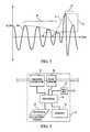
- FIG. 2illustrates an exemplary flow waveform generated by a flow sensor in accordance with one embodiment of the invention
- FIG. 3illustrates a gas delivery system according to one embodiment of the invention
- FIG. 4is a flow chart of a method of monitoring a patient in accordance with one embodiment of the invention.
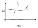
- FIG. 5is an example of templates uses to detect respiratory entry events, respiratory exit events, or both.
- FIG. 1schematically illustrates an exemplary embodiment of a patient treatment system 10 according to the principles of the present invention.
- Patient treatment system 10is capable of providing and automatically controlling the pressure of a gas delivered to a patient.
- Patient treatment system 10includes a gas delivery system 12 that controls the flow and/or pressure of breathing gas provided to the patient.
- Gas delivery system 12includes a pressure generator 14 that receives a supply of breathable gas from a breathable gas source 16 , and elevates the pressure of that gas for delivery to the airway of a patient.
- Pressure generator 14may include any device, such as a blower, piston, or bellows that is capable of elevating the pressure of the received breathable gas from source 16 for delivery to a patient.
- pressure generator 14is a blower that is driven at a constant speed during the course of the pressure support treatment to produce a constant pressure or flow rate at its output 18 .
- gas source 16is simply atmospheric air drawn into the system by pressure generator 14 .
- gas source 16comprises a tank of pressurized gas connected with pressure generator 14 .
- the tank of gascan contain any breathable gas, such as oxygen, air, or other mixture of breathable gas.
- the present inventionalso contemplates that a separate gas source 16 need not be used, but instead the pressure generator 14 can itself be defined by a canister or tank of pressurized gas, with the pressure delivered to the patient being controlled by a pressure regulator.
- FIG. 1illustrates a separate gas source 16
- the present inventioncontemplates that gas source 16 can be considered to be part of the gas delivery system 12 .
- the gas source 16can be provided in the same housing as the rest of the gas delivery system 12 .
- an external gas source 16provides the pressurized flow of breathable gas so as to constitute a pressure generator, thus eliminating the need for the separate pressure generator 14 .
- gas delivery system 12includes a control valve 20 .
- the gasis delivered to control valve 20 , with an elevated pressure, downstream of the pressure generator 14 .
- Control valve 20either alone or in combination with pressure generator 14 , controls the final pressure or flow of gas 22 exiting the gas delivery system 12 .
- Examples of a suitable control valve 20include at least one valve, such as sleeve or poppet valve that exhausts gas from the patient circuit as a method of controlling the pressure in the patient circuit.
- pressure generator 14is a blower that operates at all times at one speed and control valve 20 alone controls the final pressure and/or flow rate for gas 22 output from control valve 20 .
- the present inventionalso contemplates controlling the operating speed of pressure generator 14 in combination with control valve 20 to control the final pressure and flow rate of the breathable gas that is output by system 12 for delivery to the patient.
- a pressure or flow rate close to the desired pressure or flow ratecan be set by establishing an appropriate operating speed for pressure generator 14 along and by setting the opening in control valve 20 so that the two, operating together, determine the final pressure for the breathable gas 22 .
- the present inventionalso contemplates eliminating control valve 20 and controlling the pressure and/or the flow of gas delivered to the patient based only on the operation of pressure generator 14 .
- pressure sensor 24is a single sensor unit disposed downstream of pressure generator 14 and control valve 20 .
- pressure sensor 24may include a single sensor unit disposed elsewhere, such as at an inlet of control valve 20 , or at a location downstream from gas delivery system 12 .
- pressure sensor 24may include a plurality of sensor units disposed at various locations within gas delivery system 12 .
- Pressure sensor 24may include any device, transducer, or devices, capable of detecting the pressure of the pressurized flow of breathable gas generated by gas delivery system 12 .
- patient treatment system 10includes a flow sensor 26 .
- the pressurized flow of breathable gas 22 output from control valve 20is delivered to flow sensor 26 , which detects the instantaneous volume (V) of gas generated by respiration of the patient, and/or the instantaneous flow rate (V′) of such gas to the patient, or both.
- Flow sensor 26may include any device suitable for detecting these parameters, such as a spirometer, pneumotach, variable orifice transducer, or other conventional flow transducer. It is also known to measure flow based on the operating speed of the pressure generator or the position of the control valve. In the illustrated embodiment, flow sensor 26 is provided in the gas delivery system away from the patient. If the flow at the airway of the patient is needed, it can be estimated, using conventional techniques, based on the known pressure drop of the patient circuit and based on determination of leaks generated by exhaust port 32 and patient interface assembly 28 .
- the present inventionalso contemplates providing the flow sensor at or near a patient interface assembly 28 , which communicates the pressurized flow of breathable gas with the airway of the patient.
- a patient interface assembly 28which communicates the pressurized flow of breathable gas with the airway of the patient.
- U.S. Pat. No. 6,017,315 to Starr et al.the contents of which are incorporated herein by reference, teaches a quantitative flow member that is located at the patient interface assembly 28 .
- the present inventionalso contemplates locating sensor 26 at any location along a patient circuit 30 , as will be described.
- Patient interface assembly 28may include any non-invasive patient interface appliance for communicating the pressurized flow of breathable gas to the airway of the patient.
- patient interface assembly 28may include a nasal mask, nasal/oral mask, total face mask, or nasal cannula.
- Patient interface assembly 28may also include a headgear assembly, such as mounting straps or a harness, for removing and fastening the patient interface appliance to the patient.
- the patient interface assembly 28 and/or patient circuit 30includes a suitable exhaust port 32 for exhausting gas from these components to ambient atmosphere.
- exhaust port 32is a passive exhaust port in the form of a continuously open port that imposes a flow restriction on the exhaust gas to permit control of the pressure of gas within patient interface assembly 28 . It is to be understood, however, that exhaust port 32 can be an active exhaust port that assumes different configurations to control the exhaust rate. Examples of suitable exhaust ports are taught, for example, in U.S. Pat. Nos. 5,652,296 and 5,447,525 both to Zdrojkowski et al.
- gas delivery system 12includes a processor 34 that controls various operating aspects of the gas delivery system.
- the output of flow sensor 26 and pressure sensor 24are provided to processor 34 .
- the processoruses this information to determine the pressure of the gas, the instantaneous volume (V) of the pressurized flow of the gas, and/or the instantaneous flow rate (V′) of the gas.
- processor 34determines the instantaneous volume by integrating the flow rate detected by flow sensor 26 .
- flow sensor 26may be located relatively far from patient interface assembly 28 , in order to determine the actual flow rate of gas to the patient taking into account, for example, leaks in patient circuit 30 and elsewhere in patient delivery system 10 , processor 34 may receive the output from flow sensor 26 as an estimated patient flow.
- the processor 34processes this estimated flow information, for example, by performing leak estimation, to determine the flow of gas generated by respiration of the patient, as is known to those skilled in the art.
- Processor 34controls pressure generator 14 and the actuation of control valve 20 , thereby controlling the pressure of the pressurized flow of gas generated by gas delivery system 12 .
- processor 34comprises a processor that is suitably programmed with an algorithm or algorithms to calculate the pressure to be applied to the patient according to one of any one of various modes of ventilation.
- processor 34may be capable of controlling pressure generator 14 and/or control valve 20 based on data received from pressure sensor 24 and/or flow sensor 26 to apply the calculated pressure to the breathable gas within gas delivery system 12 .
- the gas delivery system 12includes a memory 36 associated with processor 34 for storing the programming used to perform any of a plurality of modes of ventilation, depending on which mode of ventilation is selected by the caregiver or patient using control interface 58 .
- Memory 36may also be capable of storing data regarding the operation of the gas delivery system 12 , input commands, alarm thresholds, as well as any other information pertinent to the operation of the gas delivery system 12 , such as detected values of gas flow, volume, pressure, device usage, operating temperatures, and motor speed.
- processor 34identifies respiratory events including, for example, upper airway resistance, upper airway collapse, upper airway blockage, or another respiratory event.
- processor 34comprises an event entry module 44 that identifies when the patient is entering a respiratory event based on the detection of the flow of gas generated by respiration of the patient taken by flow sensor 26 .
- the detection of the flow of gas generated by respiration of the patientincludes a determination of the flow rate.
- the detection of the flow of gasincludes a determination of the volume of the flow of gas.
- the identification of respiratory event entries, and/or other respiratory circumstances of the patientmay be based on a signal generated by flow sensor 26 that represents the flow of gas generated by respiration of the patient.
- FIG. 2illustrates a waveform 40 that corresponds to the flow measured by the flow sensor. The peaks of waveform 40 represent the flow of gas generated by inspirations of the patient, and the troughs of waveform 40 represent the flow of gas generated by exhalations of the patient.
- event entry module 44identifies an entry into a respiratory event based on the shape of the peaks and/or the troughs of waveform 40 . More particularly, a flattening 42 of waveform 40 during inspiration indicates a “flow limitation,” or blockage, within the airway causing the onset of a respiratory event. In another embodiment, event entry module 44 identifies an entry into a respiratory event based on an observed pattern of relative fluctuations in the magnitude of the peaks and/or troughs of waveform 40 . More particularly, as the peak flow of gas generated by inspiration gradually decreases, event entry module 44 identifies an event entry based on a comparison between a most recent inspiration peak and a predetermined number of previous inspiration peaks. In FIG.
- event entry module 44may identify an entry into a respiratory event based on both shape of waveform 40 during inspiration and on relative changes in the size (magnitude) of the peaks of waveform 40 that represent the flow of gas during inspiration by the patient.
- processor 34comprises an event exit module 48 that identifies respiratory effort related arousals that denote an exit from a respiratory event, or respiratory event exit.
- event exit module 48identifies an event exit (or arousal) based on an observed pattern of relative fluctuations in the flow of gas during inspiration by the patient.
- section 50 of waveform 40includes a pattern that is indicative of the relatively sharp, large inhalation(s) typically experienced by the patient during a respiratory event exit.
- event exit module 48compares the peak flow of the flow of gas generated during successive inspirations, and identifies an event exit when the determined flow indicates a general decline in the flow of gas during inspirations followed by a rapid increase in the flow of gas during inspiration.
- a plot 51 of the peak flow of waveform 40serves to emphasize this pattern.
- event exit module 48detects an event exit, or arousal, based on a difference in the flow of gas generated by consecutive inspirations of the patient. For example, if a first peak in waveform 40 associated with a first inspiration is smaller in magnitude than a second peak in waveform 40 associated with a next inspiration by greater than a threshold amount, event exit module detects a respiratory effort response arousal (RERA) indicative of an event exit. This comparison is represented in FIG. 2 as a difference 52 between successive peaks of waveform 40 .
- RERArespiratory effort response arousal
- event exit module 48first monitors waveform 40 for the pattern in the flow of gas to generated by respiration of the patient, described above, that indicates a respiratory effort related arousal, and then identifies an event exit if the difference in magnitude of consecutive peaks of waveform 40 that form the observed pattern are greater than a threshold value.
- event exit module 48identifies event exits based on the absolute magnitude of the flow detected by flow sensor 26 and/or changes in the shape of waveform 40 generated based on an output of flow sensor 26 .
- event exit module 48identifies respiratory event exits based on the peak flow.
- event entry module 44 and event exit module 48have been described above as detecting respiratory event entries and exits based on the flow of gas generated by respiration of the patient during inspiration, the scope of the invention encompasses embodiments in which expiratory flows are implemented instead.
- processor 34comprises a respiratory event module 54 that identifies a respiratory event when an identification of a respiratory event entry is followed by an identification of a respiratory event exit associated with a respiratory effort related arousal.
- respiratory event module 54communicates with event entry module 44 and event exit module 48 , and identifies a respiratory event when event exit module 48 identifies a respiratory effort related arousal immediately following an identification of a respiratory event entry by event entry module 44 .
- processor 34comprises a treatment adjustment module 56 that adjusts one or more aspects of treatment received by the patient based on the identification of a respiratory event.
- treatment adjustment module 56communicates with respiratory event module 54 , and adjusts one or more aspects of treatment when respiratory event module 54 identifies a respiratory event.
- treatment adjustment module 56may adjust the pressure of the gas delivered to the patient by gas delivery system 12 .
- the pressureis increased to provide enhanced support to the airway of the patient if respiratory events are detected.
- the pressuremay be increased to a predetermined level or by a predetermined increment.
- the pressureis decreased to provide reduced pressure support to the airway of the patient if respiratory events are not detected. The decrease can take place automatically if, for example, no events are detected within a certain time frame while the patient is being monitored.
- the pressuremay be decreased to a predetermined level or by a predetermined decrement.
- the level or the amount of the pressure adjustmentcan be variable.
- the level or amount of pressure adjustmentcan be based on the characteristic of the respiratory event.
- the present inventioncontemplates monitoring the magnitude of the peak of the gas flow waveform generated during an event exit, i.e., during section 50 of waveform 40 in FIG. 2 .
- the magnitude of this peak during one respiratory event or multiple respiratory eventscan be monitored and used to determine the pressure level to be applied to the patient. If, for example, the magnitude of the peaks flow over one or more event exits has been relatively large, the present invention contemplates increasing the pressure by a greater amount than if the magnitude of the peak flow over the event exits was smaller. This results in a more aggressive treatment of the patient to counteract the respiratory events. Conversely, if the magnitude of the peaks flow over one or more event exits has been relatively small, the pressure can be increased by a smaller amount.
- the level or amount of pressure adjustmentcan also be based on the current operating condition of the gas delivery system. For example, the if the gas delivery system is operating at a relatively high pressure, the amount of pressure increase that is to be applied to the patient as a result of detecting a respiratory event can be less than if the if the system is currently delivery a relatively low pressure to the patient.
- the present inventionstill further contemplates using the detecting of RERA events (or the lack of detection of RERA events during a certain time period) to suspend or alter other pending/ongoing therapy actions.
- the present inventioncontemplates shortening or increasing a pressure ramp, changing the type of pressure therapy being delivered, changing the auto-titration parameters, or any combination thereof depending on whether or not respiratory events are detected.
- the pressure therapyis switched from a bilevel, C-FlexTM, Bi-Flex®, or PAP® therapies to a CPAP therapy if respiratory events are detected, and vice versa.
- the present inventionalso contemplates switching between any of these modes of pressure support, or even other modes of ventilating a patient, depending on the respiratory events detected. Each of these therapies are well known in the art.
- the present inventioncontemplates providing an auto-titration pressure support therapy, in which the pressure delivered to the patient varies based on the monitored condition of the patient, and using the respiratory event detection of the present invention to alter the auto-titration pressure control technique.
- U.S. Pat. No. 6,920,887teaches an auto-titration technique that includes conducting a P opt and/or P crit search to determine the optimum pressure to deliver to the patient.
- the present inventioncontemplates using the respiratory event detection described herein, either alone or in combination with other factors, to determine whether to initiate a P opt and/or P crit search or to terminate any such search.
- U.S. patent application Ser. No. 10/268,406publication no.
- US-2003-0111079-A1teaches auto-titration techniques that include pressure ramps, statistical analysis, and decision points as to when and how to control the auto-titration algorithm.
- the present inventioncontemplates using the respiratory event detection described herein, either alone or in combination with other factors, to change the operation of the algorithm. For example, if RERA events are detected, the slope of a pressure ramp can be changed, the controller can switch to different control modules, change the threshold values to make the system more or less sensitive, and so on.
- identification of a respiratory event by respiratory event module 54may trigger any number of actions and/or operations by processor 34 .
- information corresponding to waveform 40e.g., a plot of the peak flow of waveform 40 , numerical data reflecting the data of waveform 40 , etc.
- the informationmay be stored in memory 36 .
- the informationmay be reported to an interested individual (e.g., the patient, a caregiver, an insurance provider, etc.) as documentation of the respiratory event.
- processor 34may generate and/or record other information related to the respiratory event. For example, the number of identified respiratory events may be counted, an alarm or alert may be activated when a threshold amount of respiratory events are identified, an alarm or alert may be activated for each identified respiratory event, or other actions or operations may be executed.
- modules 44 , 48 , 54 , and 56 of processor 34may be implemented in hardware, software, firmware, or in some combination of hardware, software, and/or firmware. Additionally, although modules 44 , 48 , 54 , and 56 are shown in FIG. 1 as being located in a single location, this need not be the case. In one embodiment, processor 34 is a plurality of separate processors located remotely from each other operating in conjunction, for example, over a network. In such an embodiment, some or all of modules 44 , 48 , 54 , and 56 may be located remotely from each other.
- a control interface 58provides data and commands to processor 34 of gas delivery system 12 .
- Control interface 58may include any device suitable to provide information and/or commands to processor 34 via a hardwire or wireless connection. Typical examples of control interface 58 may include a keypad, keyboard, touch pad, mouse, microphone, switches, button, dials, or any other devices that allow a user to input information to the gas delivery system 12 .
- Control interface 58may also include one or more devices suitable to provide information related to patient treatment system 10 to an individual (e.g., a patient, a caregiver, etc.) such as, for example, a screen, a printer, one or more indicator light, a speaker, or other devices that enable the provision information to the individual.
- control interface 58may be located at gas delivery system 12 or may be located remotely and communicate with processor 34 via an operative communications link (e.g., hardwired, wireless, etc.).
- control interface 58may be implemented as a Graphical User Interface (GUI) running on a computing terminal that communicates with processor 34 via a network, or other communications link.
- GUIGraphical User Interface
- patient circuit 26can be a two-limb circuit, which is common in conventional ventilators.
- the first limblike patient circuit 26 , delivers breathing gas to the patient, except that it lacks an exhaust port. Instead, the second limb carries the exhaust gases from the patient to ambient atmosphere.
- an active exhaust port in the second limbunder the control of a processor (e.g. processor 34 ) provides the desired level of positive end expiratory pressure (PEEP) to the patient.
- PEEPpositive end expiratory pressure
- gas delivery system 12An alternative embodiment of gas delivery system 12 is discussed below with reference to FIG. 3 .
- the final pressure of the gas delivered to the patientis not controlled by a control valve, either alone or in combination with pressure generator 14 .
- gas delivery system 12controls the pressure of the breathable gas based only on the output of a pressure generator 14 .
- pressure generator 14is a blower and processor 34 (as described in the first embodiment) controls the pressure of the breathable gas delivered to the patient by controlling the motor speed of pressure generator 14 .
- the present inventioncontemplates implementing the pressure of the breathable gas as detected by pressure sensor 24 and a speed monitor for the blower motor to provide feedback data to processor 34 for controlling the operation of pressure generator 14 .
- gas delivery system 12may include other conventional devices and components, such as a humidifier, heater, bacteria filter, temperature sensor, humidity sensor, and a gas sensor (e.g., a capnometer), that filter, measure, monitor, and analyze the flow of gas to or from the patient.
- a humidifiere.g., a humidifier
- heatere.g., a heater
- bacteria filtere.g., a bacteria filter
- temperature sensore.g., a humidity sensor
- a gas sensore.g., a capnometer
- FIG. 4is an exemplary illustration of a method 60 of monitoring and/or treating a patient.
- the steps of method 60are executed by processor 34 .
- a flow of gas generated by respiration of the patientis determined.
- the flow of gasis determined by flow sensor 26 as described above.
- the determined flow of the gasis monitored to identify respiratory event entries.
- event entriesare identified by event entry module 44 , as was previously described.
- method 60proceeds to a step 68 , where the determined flow of the gas is monitored to detect a respiratory event-related arousal indicative of a respiratory event exit.
- event exitsare identified by event exit module 48 , as described above.
- respiratory eventsare identified when an identification of an event entry is followed by an identification of an event exit.
- respiratory eventsare identified by respiratory event module 54 , as was explained previously.
- a respiratory eventWhen a respiratory event is identified at step 70 , one or more aspects of a treatment being received by the patient is adjusted at a step 72 . According to one embodiment, one or more aspects of the treatment are adjusted by treatment adjustment module 56 , as set forth above.
- the identification of a respiratory eventmay trigger one or more other actions and/or operations at a step 74 .
- the other actions and/or operationsmay include recording information, keeping a count of the number of respiratory events, activating an alarm, or other actions as were provided above.
- event entry module 44 and event exit module 48monitor the peak flow to determine whether the patient has suffered a respiratory event.
- the present inventionalso contemplates monitoring any waveform that is a surrogate for flow. For example, changes in volume in upstairs or expired are directly related to the patient flow. Thus, the present invention contemplates monitoring relative changes in volume (V) as another technique for detecting respiratory events.
- Other known surrogates for flowinclude signals that change based on changes in flow, such as motor speed signals, valve position signals, temperature variations—if the temperature sensor is positioned in the flow path, and pressure variations—as pressure and flow are closely correlated.
- the entry and exit eventsare monitored by comparing the peak values of the flow parameter or flow-related parameter using a statistical analysis or threshold based analysis.
- a statistical analysis or threshold based analysisFor example, the present invention discussed above uses peak flows generated during successive inspirations and identifies an event exit when the determined flow indicates a general decline in the flow of gas during inspirations followed by a rapid increase in the flow of gas during inspiration. These decline and rapid increases can be detected by monitoring the relative peaks of the flow, which is a threshold based analysis, by comparing the current peaks to an average of the previous peak, which constitutes a combination of a statistical and threshold based analysis. It is to be understood that the present invention contemplates using any technique to identify the respiratory entry and exit events.
- FIG. 5illustrates an exemplary peak flow template 80 for detecting a RERA event.
- Template 80includes a first portion 82 that corresponds to the gradual decrease of the peak flow indicative of an entry event, i.e., region 46 in FIG. 2 , and a second portion 84 that corresponds to the sharp increase in peak flow indicative of an exit event, i.e., region 50 in FIG. 2 .
- the first portion, the second portion, or bothcan be used to detect the entry events, the exit events, or both.
- the present inventioncontemplates using any suitable statistical analysis to determine degree of coincidence between the measured peak flows and the peak flow templates.
- the template illustrated in FIG. 5is merely an example of one suitable template.
- Other shapes and configurations for the templateare contemplated by the present invention, including the use of multiple templates. If multiple templates are used, the present invention contemplates that the controller select the appropriate template, for example, based on the current therapy pressures. The present invention also contemplates having the user/caregiver select the template, for example, based on how sensitive the system is to be at detecting respiratory events.
- While peak flowshave been described herein as a means for detecting the entry and/or exit events.
- Other features of the flow waveform, such as the area under the curves, or the actual flow itselfcan be used in either the threshold based or the template based techniques for detecting these events.
Landscapes
- Health & Medical Sciences (AREA)
- Emergency Medicine (AREA)
- Pulmonology (AREA)
- Engineering & Computer Science (AREA)
- Anesthesiology (AREA)
- Biomedical Technology (AREA)
- Heart & Thoracic Surgery (AREA)
- Hematology (AREA)
- Life Sciences & Earth Sciences (AREA)
- Animal Behavior & Ethology (AREA)
- General Health & Medical Sciences (AREA)
- Public Health (AREA)
- Veterinary Medicine (AREA)
- Measurement Of The Respiration, Hearing Ability, Form, And Blood Characteristics Of Living Organisms (AREA)
- Measuring And Recording Apparatus For Diagnosis (AREA)
Abstract
Description
Claims (17)
Priority Applications (7)
| Application Number | Priority Date | Filing Date | Title |
|---|---|---|---|
| US11/600,981US8025052B2 (en) | 2005-11-21 | 2006-11-17 | System and method of monitoring respiratory events |
| EP06838171.4AEP1951348B1 (en) | 2005-11-21 | 2006-11-21 | System and method of monitoring respiratory events |
| JP2008542408AJP5324920B2 (en) | 2005-11-21 | 2006-11-21 | OPERATING METHOD FOR PATIENT TREATMENT DEVICE AND PATIENT TREATMENT DEVICE |
| BRPI0618896-6ABRPI0618896A2 (en) | 2005-11-21 | 2006-11-21 | system and method for monitoring respiratory events |
| CN2006800487529ACN101588832B (en) | 2005-11-21 | 2006-11-21 | Systems and methods for monitoring respiratory events |
| PCT/US2006/045044WO2007062029A2 (en) | 2005-11-21 | 2006-11-21 | System and method of monitoring respiratory events |
| AU2006318572AAU2006318572B2 (en) | 2005-11-21 | 2006-11-21 | System and method of monitoring respiratory events |
Applications Claiming Priority (2)
| Application Number | Priority Date | Filing Date | Title |
|---|---|---|---|
| US73852905P | 2005-11-21 | 2005-11-21 | |
| US11/600,981US8025052B2 (en) | 2005-11-21 | 2006-11-17 | System and method of monitoring respiratory events |
Publications (2)
| Publication Number | Publication Date |
|---|---|
| US20070113849A1 US20070113849A1 (en) | 2007-05-24 |
| US8025052B2true US8025052B2 (en) | 2011-09-27 |
Family
ID=38052275
Family Applications (1)
| Application Number | Title | Priority Date | Filing Date |
|---|---|---|---|
| US11/600,981Active2027-09-10US8025052B2 (en) | 2005-11-21 | 2006-11-17 | System and method of monitoring respiratory events |
Country Status (7)
| Country | Link |
|---|---|
| US (1) | US8025052B2 (en) |
| EP (1) | EP1951348B1 (en) |
| JP (1) | JP5324920B2 (en) |
| CN (1) | CN101588832B (en) |
| AU (1) | AU2006318572B2 (en) |
| BR (1) | BRPI0618896A2 (en) |
| WO (1) | WO2007062029A2 (en) |
Cited By (29)
| Publication number | Priority date | Publication date | Assignee | Title |
|---|---|---|---|---|
| US8136527B2 (en) | 2003-08-18 | 2012-03-20 | Breathe Technologies, Inc. | Method and device for non-invasive ventilation with nasal interface |
| US8381729B2 (en) | 2003-06-18 | 2013-02-26 | Breathe Technologies, Inc. | Methods and devices for minimally invasive respiratory support |
| US8418694B2 (en) | 2003-08-11 | 2013-04-16 | Breathe Technologies, Inc. | Systems, methods and apparatus for respiratory support of a patient |
| US8567399B2 (en) | 2007-09-26 | 2013-10-29 | Breathe Technologies, Inc. | Methods and devices for providing inspiratory and expiratory flow relief during ventilation therapy |
| US8677999B2 (en) | 2008-08-22 | 2014-03-25 | Breathe Technologies, Inc. | Methods and devices for providing mechanical ventilation with an open airway interface |
| US8770193B2 (en) | 2008-04-18 | 2014-07-08 | Breathe Technologies, Inc. | Methods and devices for sensing respiration and controlling ventilator functions |
| US8776793B2 (en) | 2008-04-18 | 2014-07-15 | Breathe Technologies, Inc. | Methods and devices for sensing respiration and controlling ventilator functions |
| US8925545B2 (en) | 2004-02-04 | 2015-01-06 | Breathe Technologies, Inc. | Methods and devices for treating sleep apnea |
| US8939152B2 (en) | 2010-09-30 | 2015-01-27 | Breathe Technologies, Inc. | Methods, systems and devices for humidifying a respiratory tract |
| US8955518B2 (en) | 2003-06-18 | 2015-02-17 | Breathe Technologies, Inc. | Methods, systems and devices for improving ventilation in a lung area |
| US8985099B2 (en) | 2006-05-18 | 2015-03-24 | Breathe Technologies, Inc. | Tracheostoma spacer, tracheotomy method, and device for inserting a tracheostoma spacer |
| US9067003B2 (en) | 2011-05-26 | 2015-06-30 | Kalypto Medical, Inc. | Method for providing negative pressure to a negative pressure wound therapy bandage |
| US9132250B2 (en) | 2009-09-03 | 2015-09-15 | Breathe Technologies, Inc. | Methods, systems and devices for non-invasive ventilation including a non-sealing ventilation interface with an entrainment port and/or pressure feature |
| US9180270B2 (en) | 2009-04-02 | 2015-11-10 | Breathe Technologies, Inc. | Methods, systems and devices for non-invasive open ventilation with gas delivery nozzles within an outer tube |
| US9724017B2 (en) | 2013-07-03 | 2017-08-08 | Breathe Technologies, Inc. | Respiratory cycle patient ventilation flow limitation detection |
| WO2017189808A1 (en)* | 2016-04-28 | 2017-11-02 | Invent Medical Corporation | System and method for accurate estimation of intentional and unintentional leaks in flow generation systems |
| US9962512B2 (en) | 2009-04-02 | 2018-05-08 | Breathe Technologies, Inc. | Methods, systems and devices for non-invasive ventilation including a non-sealing ventilation interface with a free space nozzle feature |
| US9987402B2 (en) | 2007-12-06 | 2018-06-05 | Smith & Nephew Plc | Apparatus and method for wound volume measurement |
| US10058668B2 (en) | 2007-05-18 | 2018-08-28 | Breathe Technologies, Inc. | Methods and devices for sensing respiration and providing ventilation therapy |
| US10058644B2 (en) | 2010-09-20 | 2018-08-28 | Smith & Nephew Plc | Pressure control apparatus |
| US10099028B2 (en) | 2010-08-16 | 2018-10-16 | Breathe Technologies, Inc. | Methods, systems and devices using LOX to provide ventilatory support |
| US10252020B2 (en) | 2008-10-01 | 2019-04-09 | Breathe Technologies, Inc. | Ventilator with biofeedback monitoring and control for improving patient activity and health |
| US10792449B2 (en) | 2017-10-03 | 2020-10-06 | Breathe Technologies, Inc. | Patient interface with integrated jet pump |
| US10940281B2 (en) | 2014-10-27 | 2021-03-09 | Covidien Lp | Ventilation triggering |
| US11154672B2 (en) | 2009-09-03 | 2021-10-26 | Breathe Technologies, Inc. | Methods, systems and devices for non-invasive ventilation including a non-sealing ventilation interface with an entrainment port and/or pressure feature |
| US11253639B2 (en) | 2011-11-02 | 2022-02-22 | Smith & Nephew Plc | Reduced pressure therapy apparatuses and methods of using same |
| US11433211B2 (en) | 2016-03-17 | 2022-09-06 | Zoll Medical Corporation | Flow sensor for ventilation |
| US11478594B2 (en) | 2018-05-14 | 2022-10-25 | Covidien Lp | Systems and methods for respiratory effort detection utilizing signal distortion |
| US11752287B2 (en) | 2018-10-03 | 2023-09-12 | Covidien Lp | Systems and methods for automatic cycling or cycling detection |
Families Citing this family (40)
| Publication number | Priority date | Publication date | Assignee | Title |
|---|---|---|---|---|
| US5915379A (en)* | 1997-03-14 | 1999-06-29 | Nellcor Puritan Bennett Incorporated | Graphic user interface for a patient ventilator |
| ES2592262T3 (en) | 2003-08-04 | 2016-11-29 | Carefusion 203, Inc. | Portable respirator system |
| US7607437B2 (en)* | 2003-08-04 | 2009-10-27 | Cardinal Health 203, Inc. | Compressor control system and method for a portable ventilator |
| US8156937B2 (en)* | 2003-08-04 | 2012-04-17 | Carefusion 203, Inc. | Portable ventilator system |
| US8118024B2 (en) | 2003-08-04 | 2012-02-21 | Carefusion 203, Inc. | Mechanical ventilation system utilizing bias valve |
| US7527053B2 (en)* | 2003-08-04 | 2009-05-05 | Cardinal Health 203, Inc. | Method and apparatus for attenuating compressor noise |
| US8021310B2 (en)* | 2006-04-21 | 2011-09-20 | Nellcor Puritan Bennett Llc | Work of breathing display for a ventilation system |
| US7784461B2 (en) | 2006-09-26 | 2010-08-31 | Nellcor Puritan Bennett Llc | Three-dimensional waveform display for a breathing assistance system |
| JP2020036949A (en)* | 2007-05-11 | 2020-03-12 | レスメド・プロプライエタリー・リミテッド | Automatic control for flow restriction detection. |
| NZ580125A (en) | 2007-05-11 | 2012-06-29 | Resmed Ltd | Automated control for detection of flow limitation |
| EP2017586A1 (en)* | 2007-07-20 | 2009-01-21 | Map-Medizintechnologie GmbH | Monitor for CPAP/Ventilator apparatus |
| US7997885B2 (en)* | 2007-12-03 | 2011-08-16 | Carefusion 303, Inc. | Roots-type blower reduced acoustic signature method and apparatus |
| US8888711B2 (en)* | 2008-04-08 | 2014-11-18 | Carefusion 203, Inc. | Flow sensor |
| US8808178B2 (en)* | 2008-04-30 | 2014-08-19 | Welch Allyn, Inc. | On demand help/in-service for a medical device |
| DE102009047246A1 (en) | 2008-12-01 | 2010-06-10 | Fisher & Paykel Healthcare Ltd., East Tamaki | nasal cannula |
| USD638852S1 (en) | 2009-12-04 | 2011-05-31 | Nellcor Puritan Bennett Llc | Ventilator display screen with an alarm icon |
| US9119925B2 (en) | 2009-12-04 | 2015-09-01 | Covidien Lp | Quick initiation of respiratory support via a ventilator user interface |
| US8335992B2 (en) | 2009-12-04 | 2012-12-18 | Nellcor Puritan Bennett Llc | Visual indication of settings changes on a ventilator graphical user interface |
| USD649157S1 (en) | 2009-12-04 | 2011-11-22 | Nellcor Puritan Bennett Llc | Ventilator display screen with a user interface |
| US8924878B2 (en) | 2009-12-04 | 2014-12-30 | Covidien Lp | Display and access to settings on a ventilator graphical user interface |
| US9262588B2 (en) | 2009-12-18 | 2016-02-16 | Covidien Lp | Display of respiratory data graphs on a ventilator graphical user interface |
| US8499252B2 (en) | 2009-12-18 | 2013-07-30 | Covidien Lp | Display of respiratory data graphs on a ventilator graphical user interface |
| WO2011086435A2 (en)* | 2010-01-14 | 2011-07-21 | Koninklijke Philips Electronics N.V. | Servo ventilation using negative pressure support |
| GB2500145B (en)* | 2010-12-03 | 2016-11-02 | Fisher & Paykel Healthcare Ltd | Apparatus for supplying gases |
| WO2012095764A1 (en)* | 2011-01-14 | 2012-07-19 | Koninklijke Philips Electronics N.V. | Measuring continuity of therapy associated with a respiratory treatment device |
| US10576223B2 (en) | 2011-06-15 | 2020-03-03 | Koninklijke Phlips N.V. | Unlocking a respiratory therapy mode |
| US11406778B2 (en) | 2011-06-15 | 2022-08-09 | Koninklijke Philips N.V. | Unlocking a respiratory mode |
| JP6223340B2 (en)* | 2011-08-25 | 2017-11-01 | コーニンクレッカ フィリップス エヌ ヴェKoninklijke Philips N.V. | Method and apparatus for controlling a ventilator device |
| EP2804654A4 (en) | 2012-02-15 | 2015-08-26 | Fisher & Paykel Healthcare Ltd | System, apparatus and methods for supplying gases |
| US20130239961A1 (en)* | 2012-03-16 | 2013-09-19 | Smartmed Usa Inc. | Apparatus, computer program, method and system for portable breathing assistance |
| CN102614633B (en)* | 2012-04-16 | 2014-11-19 | 长春大学 | Breathing training method and system for language training of hearing-impaired children |
| US10362967B2 (en) | 2012-07-09 | 2019-07-30 | Covidien Lp | Systems and methods for missed breath detection and indication |
| JP6273420B2 (en)* | 2013-03-18 | 2018-02-07 | 株式会社メトラン | Expiratory valve and respiratory assistance device |
| CN103413038A (en)* | 2013-08-01 | 2013-11-27 | 雷英杰 | Vector quantization based long-term intuitionistic fuzzy time series prediction method |
| TWI564041B (en)* | 2014-08-28 | 2017-01-01 | Apex Medical Corp | A breathing gas supply system and a control method thereof, and a computer program product for executing the method |
| CN105083501B (en)* | 2015-09-09 | 2018-01-30 | 中国人民解放军海军医学研究所 | Aqualung |
| CA3063524A1 (en)* | 2017-05-19 | 2018-11-22 | Trudell Medical International | Positive expiratory pressure device |
| US11672934B2 (en) | 2020-05-12 | 2023-06-13 | Covidien Lp | Remote ventilator adjustment |
| CN112363139A (en)* | 2020-11-02 | 2021-02-12 | 深圳大学 | Human body breathing time length detection method and device based on amplitude characteristics and storage medium |
| US20230044168A1 (en)* | 2021-08-04 | 2023-02-09 | Infosys Limited | Air purifier mask and method thereof |
Citations (24)
| Publication number | Priority date | Publication date | Assignee | Title |
|---|---|---|---|---|
| US5245995A (en)* | 1987-06-26 | 1993-09-21 | Rescare Limited | Device and method for monitoring breathing during sleep, control of CPAP treatment, and preventing of apnea |
| US5313937A (en)* | 1989-09-22 | 1994-05-24 | Respironics Inc. | Leak compensation method and apparatus for a breathing system |
| US5335654A (en)* | 1992-05-07 | 1994-08-09 | New York University | Method and apparatus for continuous adjustment of positive airway pressure for treating obstructive sleep apnea |
| US5447525A (en) | 1993-09-15 | 1995-09-05 | Medtronic, Inc. | Pacemaker which adapts to minimize current drain and provide desired capture safety margin |
| US5458137A (en)* | 1991-06-14 | 1995-10-17 | Respironics, Inc. | Method and apparatus for controlling sleep disorder breathing |
| US5535739A (en)* | 1992-05-07 | 1996-07-16 | New York University | Method and apparatus for optimizing the continuous positive airway pressure for treating obstructive sleep apnea |
| US5652296A (en) | 1994-08-19 | 1997-07-29 | Minnesota Mining And Manufacturing Company | Water-based adhesives |
| US5704923A (en) | 1995-08-31 | 1998-01-06 | Chiu-Hsiung; Chiang | Liquid level detector and alarm device for drip infusion sets |
| US5823187A (en)* | 1991-11-01 | 1998-10-20 | Estes; Mark C. | Sleep apnea treatment apparatus with a therapy delay circuit arrangement |
| US5931160A (en)* | 1995-12-08 | 1999-08-03 | Cardiopulmonary Corporation | Ventilator control system and method |
| US6017315A (en) | 1998-02-25 | 2000-01-25 | Respironics, Inc. | Patient monitor and method of using same |
| US6029665A (en)* | 1993-11-05 | 2000-02-29 | Resmed Limited | Determination of patency of airway |
| US6085747A (en)* | 1991-06-14 | 2000-07-11 | Respironics, Inc. | Method and apparatus for controlling sleep disorder breathing |
| US6401713B1 (en)* | 1999-05-05 | 2002-06-11 | Respironics, Inc. | Apparatus and method of providing continuous positive airway pressure |
| US20020088465A1 (en)* | 2000-09-25 | 2002-07-11 | Hill Peter D. | Method and apparatus for providing variable positive airway pressure |
| US6436053B1 (en)* | 1997-10-01 | 2002-08-20 | Boston Medical Technologies, Inc. | Method and apparatus for enhancing patient compliance during inspiration measurements |
| US6463930B2 (en)* | 1995-12-08 | 2002-10-15 | James W. Biondi | System for automatically weaning a patient from a ventilator, and method thereof |
| WO2003030804A2 (en)* | 2001-10-12 | 2003-04-17 | Ric Investments, Inc. | Auto-titration pressure support system and method of using same |
| US6626175B2 (en)* | 2000-10-06 | 2003-09-30 | Respironics, Inc. | Medical ventilator triggering and cycling method and mechanism |
| US6731984B2 (en) | 2001-06-07 | 2004-05-04 | Medtronic, Inc. | Method for providing a therapy to a patient involving modifying the therapy after detecting an onset of sleep in the patient, and implantable medical device embodying same |
| US6920887B2 (en) | 2003-08-26 | 2005-07-26 | Albert Chong-Jen Lo | Connector for a rib and a spreader of a parasol |
| US20060009708A1 (en) | 2003-08-14 | 2006-01-12 | Rapoport David M | Positive airway pressure system and method for treatment of sleeping disorder in patient |
| US20060102179A1 (en) | 2003-08-14 | 2006-05-18 | Rapoport David M | System and method for diagnosis and treatment of a breathing pattern of a patient |
| US20070062533A1 (en)* | 2005-09-21 | 2007-03-22 | Choncholas Gary J | Apparatus and method for identifying FRC and PEEP characteristics |
Family Cites Families (8)
| Publication number | Priority date | Publication date | Assignee | Title |
|---|---|---|---|---|
| US268406A (en) | 1882-12-05 | Fire and burglar proof safe | ||
| JPS60261427A (en)* | 1984-06-11 | 1985-12-24 | 株式会社東芝 | Patient monitor apparatus |
| JPH078472A (en)* | 1993-06-23 | 1995-01-13 | Nippondenso Co Ltd | Breathing amount measurement device |
| US6142950A (en)* | 1998-12-10 | 2000-11-07 | Individual Monitoring Systems, Inc. | Non-tethered apnea screening device |
| AU2002951984A0 (en)* | 2002-10-10 | 2002-10-31 | Compumedics Limited | Sleep quality and auto cpap awakening |
| DE10248590B4 (en)* | 2002-10-17 | 2016-10-27 | Resmed R&D Germany Gmbh | Method and device for carrying out a signal-processing observation of a measurement signal associated with the respiratory activity of a person |
| AU2004208574B2 (en)* | 2003-01-30 | 2007-08-30 | Compumedics Limited | Algorithm for automatic positive air pressure titration |
| EP1605998A1 (en)* | 2003-03-17 | 2005-12-21 | MAP Medizin-Technologie GmbH | Method and arrangement for the titration of physiological measuring signals in conjunction with the observation of a patient in terms of sleep-related respiratory problems |
- 2006
- 2006-11-17USUS11/600,981patent/US8025052B2/enactiveActive
- 2006-11-21EPEP06838171.4Apatent/EP1951348B1/ennot_activeCeased
- 2006-11-21AUAU2006318572Apatent/AU2006318572B2/ennot_activeCeased
- 2006-11-21JPJP2008542408Apatent/JP5324920B2/ennot_activeExpired - Fee Related
- 2006-11-21CNCN2006800487529Apatent/CN101588832B/ennot_activeExpired - Fee Related
- 2006-11-21BRBRPI0618896-6Apatent/BRPI0618896A2/ennot_activeApplication Discontinuation
- 2006-11-21WOPCT/US2006/045044patent/WO2007062029A2/enactiveApplication Filing
Patent Citations (31)
| Publication number | Priority date | Publication date | Assignee | Title |
|---|---|---|---|---|
| US5245995A (en)* | 1987-06-26 | 1993-09-21 | Rescare Limited | Device and method for monitoring breathing during sleep, control of CPAP treatment, and preventing of apnea |
| US5313937A (en)* | 1989-09-22 | 1994-05-24 | Respironics Inc. | Leak compensation method and apparatus for a breathing system |
| US6085747A (en)* | 1991-06-14 | 2000-07-11 | Respironics, Inc. | Method and apparatus for controlling sleep disorder breathing |
| US5458137A (en)* | 1991-06-14 | 1995-10-17 | Respironics, Inc. | Method and apparatus for controlling sleep disorder breathing |
| US5823187A (en)* | 1991-11-01 | 1998-10-20 | Estes; Mark C. | Sleep apnea treatment apparatus with a therapy delay circuit arrangement |
| US6488634B1 (en)* | 1992-05-07 | 2002-12-03 | New York University | Method and apparatus for optimizing the continuous positive airway pressure for treating obstructive sleep apnea |
| US5535739A (en)* | 1992-05-07 | 1996-07-16 | New York University | Method and apparatus for optimizing the continuous positive airway pressure for treating obstructive sleep apnea |
| US6793629B2 (en) | 1992-05-07 | 2004-09-21 | New York University | Method and apparatus for optimizing the continuous positive airway pressure for treating obstructive sleep apnea |
| US5335654A (en)* | 1992-05-07 | 1994-08-09 | New York University | Method and apparatus for continuous adjustment of positive airway pressure for treating obstructive sleep apnea |
| US5447525A (en) | 1993-09-15 | 1995-09-05 | Medtronic, Inc. | Pacemaker which adapts to minimize current drain and provide desired capture safety margin |
| US6138675A (en)* | 1993-11-05 | 2000-10-31 | Resmed Ltd. | Determination of the occurrence of an apnea |
| US6029665A (en)* | 1993-11-05 | 2000-02-29 | Resmed Limited | Determination of patency of airway |
| US5652296A (en) | 1994-08-19 | 1997-07-29 | Minnesota Mining And Manufacturing Company | Water-based adhesives |
| US5704923A (en) | 1995-08-31 | 1998-01-06 | Chiu-Hsiung; Chiang | Liquid level detector and alarm device for drip infusion sets |
| US5931160A (en)* | 1995-12-08 | 1999-08-03 | Cardiopulmonary Corporation | Ventilator control system and method |
| US6463930B2 (en)* | 1995-12-08 | 2002-10-15 | James W. Biondi | System for automatically weaning a patient from a ventilator, and method thereof |
| US6436053B1 (en)* | 1997-10-01 | 2002-08-20 | Boston Medical Technologies, Inc. | Method and apparatus for enhancing patient compliance during inspiration measurements |
| US6017315A (en) | 1998-02-25 | 2000-01-25 | Respironics, Inc. | Patient monitor and method of using same |
| US6401713B1 (en)* | 1999-05-05 | 2002-06-11 | Respironics, Inc. | Apparatus and method of providing continuous positive airway pressure |
| US20020088465A1 (en)* | 2000-09-25 | 2002-07-11 | Hill Peter D. | Method and apparatus for providing variable positive airway pressure |
| US6626175B2 (en)* | 2000-10-06 | 2003-09-30 | Respironics, Inc. | Medical ventilator triggering and cycling method and mechanism |
| US6731984B2 (en) | 2001-06-07 | 2004-05-04 | Medtronic, Inc. | Method for providing a therapy to a patient involving modifying the therapy after detecting an onset of sleep in the patient, and implantable medical device embodying same |
| WO2003030804A2 (en)* | 2001-10-12 | 2003-04-17 | Ric Investments, Inc. | Auto-titration pressure support system and method of using same |
| US20030111079A1 (en) | 2001-10-12 | 2003-06-19 | Greg Matthews | Auto-titration pressure support system and method of using same |
| US20040187870A1 (en)* | 2001-10-12 | 2004-09-30 | Greg Matthews | Auto-titration pressure support system and method of using same |
| US7168429B2 (en)* | 2001-10-12 | 2007-01-30 | Ric Investments, Llc | Auto-titration pressure support system and method of using same |
| US20060009708A1 (en) | 2003-08-14 | 2006-01-12 | Rapoport David M | Positive airway pressure system and method for treatment of sleeping disorder in patient |
| US6988994B2 (en) | 2003-08-14 | 2006-01-24 | New York University | Positive airway pressure system and method for treatment of sleeping disorder in patient |
| US20060102179A1 (en) | 2003-08-14 | 2006-05-18 | Rapoport David M | System and method for diagnosis and treatment of a breathing pattern of a patient |
| US6920887B2 (en) | 2003-08-26 | 2005-07-26 | Albert Chong-Jen Lo | Connector for a rib and a spreader of a parasol |
| US20070062533A1 (en)* | 2005-09-21 | 2007-03-22 | Choncholas Gary J | Apparatus and method for identifying FRC and PEEP characteristics |
Non-Patent Citations (1)
| Title |
|---|
| "Sleep-Related Breathing Disorders in Adults: Recommendations for Syndrome Definition and Measurement Techniques in Clinical Research", Apr. 1999. |
Cited By (56)
| Publication number | Priority date | Publication date | Assignee | Title |
|---|---|---|---|---|
| US8955518B2 (en) | 2003-06-18 | 2015-02-17 | Breathe Technologies, Inc. | Methods, systems and devices for improving ventilation in a lung area |
| US8381729B2 (en) | 2003-06-18 | 2013-02-26 | Breathe Technologies, Inc. | Methods and devices for minimally invasive respiratory support |
| US8418694B2 (en) | 2003-08-11 | 2013-04-16 | Breathe Technologies, Inc. | Systems, methods and apparatus for respiratory support of a patient |
| US8573219B2 (en) | 2003-08-18 | 2013-11-05 | Breathe Technologies, Inc. | Method and device for non-invasive ventilation with nasal interface |
| US8136527B2 (en) | 2003-08-18 | 2012-03-20 | Breathe Technologies, Inc. | Method and device for non-invasive ventilation with nasal interface |
| US8925545B2 (en) | 2004-02-04 | 2015-01-06 | Breathe Technologies, Inc. | Methods and devices for treating sleep apnea |
| US8985099B2 (en) | 2006-05-18 | 2015-03-24 | Breathe Technologies, Inc. | Tracheostoma spacer, tracheotomy method, and device for inserting a tracheostoma spacer |
| US10058668B2 (en) | 2007-05-18 | 2018-08-28 | Breathe Technologies, Inc. | Methods and devices for sensing respiration and providing ventilation therapy |
| US8567399B2 (en) | 2007-09-26 | 2013-10-29 | Breathe Technologies, Inc. | Methods and devices for providing inspiratory and expiratory flow relief during ventilation therapy |
| US12029549B2 (en) | 2007-12-06 | 2024-07-09 | Smith & Nephew Plc | Apparatus and method for wound volume measurement |
| US9987402B2 (en) | 2007-12-06 | 2018-06-05 | Smith & Nephew Plc | Apparatus and method for wound volume measurement |
| US8776793B2 (en) | 2008-04-18 | 2014-07-15 | Breathe Technologies, Inc. | Methods and devices for sensing respiration and controlling ventilator functions |
| US8770193B2 (en) | 2008-04-18 | 2014-07-08 | Breathe Technologies, Inc. | Methods and devices for sensing respiration and controlling ventilator functions |
| US8677999B2 (en) | 2008-08-22 | 2014-03-25 | Breathe Technologies, Inc. | Methods and devices for providing mechanical ventilation with an open airway interface |
| US10252020B2 (en) | 2008-10-01 | 2019-04-09 | Breathe Technologies, Inc. | Ventilator with biofeedback monitoring and control for improving patient activity and health |
| US10232136B2 (en) | 2009-04-02 | 2019-03-19 | Breathe Technologies, Inc. | Methods, systems and devices for non-invasive open ventilation for treating airway obstructions |
| US11707591B2 (en) | 2009-04-02 | 2023-07-25 | Breathe Technologies, Inc. | Methods, systems and devices for non-invasive open ventilation with gas delivery nozzles with an outer tube |
| US9675774B2 (en) | 2009-04-02 | 2017-06-13 | Breathe Technologies, Inc. | Methods, systems and devices for non-invasive open ventilation with gas delivery nozzles in free space |
| US12364835B2 (en) | 2009-04-02 | 2025-07-22 | Breathe Technologies, Inc. | Methods, systems and devices for non-invasive ventilation with gas delivery nozzles in free space |
| US12161807B2 (en) | 2009-04-02 | 2024-12-10 | Breathe Technologies, Inc. | Methods, systems and devices for non-invasive open ventilation with gas delivery nozzles within nasal pillows |
| US9962512B2 (en) | 2009-04-02 | 2018-05-08 | Breathe Technologies, Inc. | Methods, systems and devices for non-invasive ventilation including a non-sealing ventilation interface with a free space nozzle feature |
| US9227034B2 (en) | 2009-04-02 | 2016-01-05 | Beathe Technologies, Inc. | Methods, systems and devices for non-invasive open ventilation for treating airway obstructions |
| US10046133B2 (en) | 2009-04-02 | 2018-08-14 | Breathe Technologies, Inc. | Methods, systems and devices for non-invasive open ventilation for providing ventilation support |
| US9180270B2 (en) | 2009-04-02 | 2015-11-10 | Breathe Technologies, Inc. | Methods, systems and devices for non-invasive open ventilation with gas delivery nozzles within an outer tube |
| US10709864B2 (en) | 2009-04-02 | 2020-07-14 | Breathe Technologies, Inc. | Methods, systems and devices for non-invasive open ventilation with gas delivery nozzles with an outer tube |
| US10695519B2 (en) | 2009-04-02 | 2020-06-30 | Breathe Technologies, Inc. | Methods, systems and devices for non-invasive open ventilation with gas delivery nozzles within nasal pillows |
| US11896766B2 (en) | 2009-04-02 | 2024-02-13 | Breathe Technologies, Inc. | Methods, systems and devices for non-invasive ventilation with gas delivery nozzles in free space |
| US11103667B2 (en) | 2009-04-02 | 2021-08-31 | Breathe Technologies, Inc. | Methods, systems and devices for non-invasive ventilation with gas delivery nozzles in free space |
| US9132250B2 (en) | 2009-09-03 | 2015-09-15 | Breathe Technologies, Inc. | Methods, systems and devices for non-invasive ventilation including a non-sealing ventilation interface with an entrainment port and/or pressure feature |
| US10265486B2 (en) | 2009-09-03 | 2019-04-23 | Breathe Technologies, Inc. | Methods, systems and devices for non-invasive ventilation including a non-sealing ventilation interface with an entrainment port and/or pressure feature |
| US11154672B2 (en) | 2009-09-03 | 2021-10-26 | Breathe Technologies, Inc. | Methods, systems and devices for non-invasive ventilation including a non-sealing ventilation interface with an entrainment port and/or pressure feature |
| US12048813B2 (en) | 2009-09-03 | 2024-07-30 | Breathe Technologies, Inc. | Methods, systems and devices for non-invasive ventilation including a non-sealing ventilation interface with an entrainment port and/or pressure feature |
| US10099028B2 (en) | 2010-08-16 | 2018-10-16 | Breathe Technologies, Inc. | Methods, systems and devices using LOX to provide ventilatory support |
| US11027051B2 (en) | 2010-09-20 | 2021-06-08 | Smith & Nephew Plc | Pressure control apparatus |
| US11534540B2 (en) | 2010-09-20 | 2022-12-27 | Smith & Nephew Plc | Pressure control apparatus |
| US12226611B2 (en) | 2010-09-20 | 2025-02-18 | Smith & Nephew Plc | Pressure control apparatus |
| US10058644B2 (en) | 2010-09-20 | 2018-08-28 | Smith & Nephew Plc | Pressure control apparatus |
| US10105473B2 (en) | 2010-09-20 | 2018-10-23 | Smith & Nephew Plc | Pressure control apparatus |
| US9358358B2 (en) | 2010-09-30 | 2016-06-07 | Breathe Technologies, Inc. | Methods, systems and devices for humidifying a respiratory tract |
| US8939152B2 (en) | 2010-09-30 | 2015-01-27 | Breathe Technologies, Inc. | Methods, systems and devices for humidifying a respiratory tract |
| US9067003B2 (en) | 2011-05-26 | 2015-06-30 | Kalypto Medical, Inc. | Method for providing negative pressure to a negative pressure wound therapy bandage |
| US10300178B2 (en) | 2011-05-26 | 2019-05-28 | Smith & Nephew, Inc. | Method for providing negative pressure to a negative pressure wound therapy bandage |
| US12097095B2 (en) | 2011-05-26 | 2024-09-24 | Smith & Nephew, Inc. | Method and apparatus for providing negative pressure to a negative pressure wound therapy bandage |
| US11648342B2 (en) | 2011-11-02 | 2023-05-16 | Smith & Nephew Plc | Reduced pressure therapy apparatuses and methods of using same |
| US11253639B2 (en) | 2011-11-02 | 2022-02-22 | Smith & Nephew Plc | Reduced pressure therapy apparatuses and methods of using same |
| US9724017B2 (en) | 2013-07-03 | 2017-08-08 | Breathe Technologies, Inc. | Respiratory cycle patient ventilation flow limitation detection |
| US10940281B2 (en) | 2014-10-27 | 2021-03-09 | Covidien Lp | Ventilation triggering |
| US11712174B2 (en) | 2014-10-27 | 2023-08-01 | Covidien Lp | Ventilation triggering |
| US12029857B2 (en) | 2016-03-17 | 2024-07-09 | Zoll Medical Corporation | Flow sensor for ventilation |
| US11433211B2 (en) | 2016-03-17 | 2022-09-06 | Zoll Medical Corporation | Flow sensor for ventilation |
| WO2017189808A1 (en)* | 2016-04-28 | 2017-11-02 | Invent Medical Corporation | System and method for accurate estimation of intentional and unintentional leaks in flow generation systems |
| US10869977B2 (en) | 2016-04-28 | 2020-12-22 | Invent Medical Corporation | System and method for accurate estimation of intentional and unintentional leaks in flow generation systems |
| US12017002B2 (en) | 2017-10-03 | 2024-06-25 | Breathe Technologies, Inc. | Patient interface with integrated jet pump |
| US10792449B2 (en) | 2017-10-03 | 2020-10-06 | Breathe Technologies, Inc. | Patient interface with integrated jet pump |
| US11478594B2 (en) | 2018-05-14 | 2022-10-25 | Covidien Lp | Systems and methods for respiratory effort detection utilizing signal distortion |
| US11752287B2 (en) | 2018-10-03 | 2023-09-12 | Covidien Lp | Systems and methods for automatic cycling or cycling detection |
Also Published As
| Publication number | Publication date |
|---|---|
| EP1951348A4 (en) | 2013-04-03 |
| EP1951348A2 (en) | 2008-08-06 |
| CN101588832B (en) | 2013-03-27 |
| EP1951348B1 (en) | 2017-05-03 |
| CN101588832A (en) | 2009-11-25 |
| AU2006318572A1 (en) | 2007-05-31 |
| WO2007062029A2 (en) | 2007-05-31 |
| AU2006318572B2 (en) | 2013-09-19 |
| WO2007062029A3 (en) | 2009-05-07 |
| JP2009516573A (en) | 2009-04-23 |
| JP5324920B2 (en) | 2013-10-23 |
| BRPI0618896A2 (en) | 2011-09-13 |
| US20070113849A1 (en) | 2007-05-24 |
Similar Documents
| Publication | Publication Date | Title |
|---|---|---|
| US8025052B2 (en) | System and method of monitoring respiratory events | |
| US12220529B2 (en) | Breathing assistance apparatus | |
| US11497869B2 (en) | Methods and systems for adaptive base flow | |
| US20190099569A1 (en) | System, apparatus and method for supplying gases | |
| AU2005225099B2 (en) | Medical ventilator triggering and cycling method and mechanism | |
| US20010035186A1 (en) | Parameter variation for proportional assist ventilation or proportional positive airway pressure support devices | |
| EP2686050A1 (en) | Breathing apparatus and method for support ventilation | |
| JP2009539433A5 (en) | ||
| CA2611603A1 (en) | Respiratory device measurement system | |
| US7798143B1 (en) | Respiratory treatment device with patient reporting |
Legal Events
| Date | Code | Title | Description |
|---|---|---|---|
| AS | Assignment | Owner name:RIC INVESTMENTS, LLC, DELAWARE Free format text:ASSIGNMENT OF ASSIGNORS INTEREST;ASSIGNORS:MATTHEWS, GREG;BALOA, LEONARDO A.;REEL/FRAME:018617/0227 Effective date:20061117 | |
| STCF | Information on status: patent grant | Free format text:PATENTED CASE | |
| FPAY | Fee payment | Year of fee payment:4 | |
| MAFP | Maintenance fee payment | Free format text:PAYMENT OF MAINTENANCE FEE, 8TH YEAR, LARGE ENTITY (ORIGINAL EVENT CODE: M1552); ENTITY STATUS OF PATENT OWNER: LARGE ENTITY Year of fee payment:8 | |
| AS | Assignment | Owner name:RESPIRONICS, INC.., PENNSYLVANIA Free format text:MERGER;ASSIGNOR:RIC INVESTMENTS, LLC;REEL/FRAME:062900/0553 Effective date:20180619 | |
| AS | Assignment | Owner name:PHILIPS RS NORTH AMERICA LLC, PENNSYLVANIA Free format text:CHANGE OF NAME;ASSIGNOR:RESPIRONICS, INC.;REEL/FRAME:063012/0881 Effective date:20201027 | |
| MAFP | Maintenance fee payment | Free format text:PAYMENT OF MAINTENANCE FEE, 12TH YEAR, LARGE ENTITY (ORIGINAL EVENT CODE: M1553); ENTITY STATUS OF PATENT OWNER: LARGE ENTITY Year of fee payment:12 |