US8024938B2 - Method for determining evaporator airflow verification - Google Patents
Method for determining evaporator airflow verificationDownload PDFInfo
- Publication number
- US8024938B2 US8024938B2US11/985,170US98517007AUS8024938B2US 8024938 B2US8024938 B2US 8024938B2US 98517007 AUS98517007 AUS 98517007AUS 8024938 B2US8024938 B2US 8024938B2
- Authority
- US
- United States
- Prior art keywords
- temperature
- condenser
- target
- superheat
- bulb
- Prior art date
- Legal status (The legal status is an assumption and is not a legal conclusion. Google has not performed a legal analysis and makes no representation as to the accuracy of the status listed.)
- Expired - Fee Related, expires
Links
- 238000000034methodMethods0.000titleclaimsabstractdescription52
- 238000012795verificationMethods0.000titleclaimsabstractdescription40
- 238000012360testing methodMethods0.000claimsabstractdescription36
- 238000005057refrigerationMethods0.000claimsdescription50
- 238000001704evaporationMethods0.000claimsdescription41
- 239000003507refrigerantSubstances0.000claimsdescription40
- 239000007788liquidSubstances0.000claimsdescription20
- 229920006395saturated elastomerPolymers0.000claimsdescription12
- 238000001816coolingMethods0.000claimsdescription9
- 238000012937correctionMethods0.000claimsdescription3
- 238000010998test methodMethods0.000claims2
- 230000006835compressionEffects0.000abstractdescription4
- 238000007906compressionMethods0.000abstractdescription4
- 238000005259measurementMethods0.000description8
- 238000004378air conditioningMethods0.000description4
- 238000013459approachMethods0.000description3
- 238000009434installationMethods0.000description3
- 238000002405diagnostic procedureMethods0.000description2
- 230000005611electricityEffects0.000description2
- 238000011156evaluationMethods0.000description2
- 230000008569processEffects0.000description2
- 238000012549trainingMethods0.000description2
- 230000008901benefitEffects0.000description1
- 230000000694effectsEffects0.000description1
- 238000010438heat treatmentMethods0.000description1
- KJLLKLRVCJAFRY-UHFFFAOYSA-NmebutizideChemical compoundClC1=C(S(N)(=O)=O)C=C2S(=O)(=O)NC(C(C)C(C)CC)NC2=C1KJLLKLRVCJAFRY-UHFFFAOYSA-N0.000description1
- 238000012986modificationMethods0.000description1
- 230000004048modificationEffects0.000description1
- 230000000246remedial effectEffects0.000description1
- 230000004044responseEffects0.000description1
- 230000000630rising effectEffects0.000description1
- 238000009423ventilationMethods0.000description1
- 238000010792warmingMethods0.000description1
Images


Classifications
- F—MECHANICAL ENGINEERING; LIGHTING; HEATING; WEAPONS; BLASTING
- F25—REFRIGERATION OR COOLING; COMBINED HEATING AND REFRIGERATION SYSTEMS; HEAT PUMP SYSTEMS; MANUFACTURE OR STORAGE OF ICE; LIQUEFACTION SOLIDIFICATION OF GASES
- F25B—REFRIGERATION MACHINES, PLANTS OR SYSTEMS; COMBINED HEATING AND REFRIGERATION SYSTEMS; HEAT PUMP SYSTEMS
- F25B49/00—Arrangement or mounting of control or safety devices
- F25B49/005—Arrangement or mounting of control or safety devices of safety devices
Definitions
- the present inventionrelates generally to vapor compression cycle equipment (refrigeration and air conditioning equipment) and, more specifically, to a method for providing a field test protocol for refrigeration and airflow verification for existing commercial units.
- HVACHeating, Ventilation and Air Conditioning
- HVAC techniciansdo not (or are not trained to) finely tune refrigeration systems upon installation, and that proper charge in refrigeration systems tend to degrade over time. More disturbing was the fact that HVAC technicians did not understand the relationship between refrigerant charge and operating efficiency.
- the present inventiondescribes a method of evaluating the efficiency of condensers and evaporators in vapor compression cycle equipment.
- the methoddiscloses setting up the refrigeration system, the testing setup, and protocols for the evaluations of both condensers and evaporators.
- the protocolcan be applied to packaged or split systems, air-cooled air conditioning or heat pump systems, constant volume or variable volume indoor fans, and constant speed or variable speed compressors, single or tandem in circuit, including un-loaders.
- the present inventionalso describes a series of calculations to be used in the evaluation, and identifies the point at which corrections will be necessary.
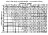
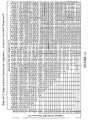
- FIG. 1Ais the Title 24 ACM RD Table for determining Target Superheat
- FIG. 1Bis a continuation of the Table shown in FIG. 1A ;
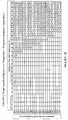
- FIG. 2is the Title 24 ACM RD Table for determining Target Temperature Split
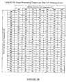
- FIG. 3Ais a chart showing Target Evaporating Temperature, TxV Metering Device in accordance with the present invention.
- FIG. 3Bis a chart showing Target Evaporating Temperature, Non-TxV Metering Device in accordance with the present invention.
- FIG. 4is a chart outlining the basic steps of the method and process according to the present invention.
- the method/process for providing a field test protocol for evaporator airflow verification on existing vapor compression cycle equipmentwill be disclosed.
- the primary steps in the subject methodare presented in FIG. 4 .
- Attachment 1titled VERIFIED CHARGE AND AIRFLOW SERVICES—TECHNICAL SPECIFICATIONS
- Attachment 2titled HVAC TRAINING, INSTALLATION & MAINTENANCE PROGRAM—TECHNICAL SPECIFICATIONS
- Outdoor air dampershould be closed and return air damper open (100% return air). When closing the outdoor air damper is not practical, testing may be completed with the outdoor air damper at minimum position with no more than approximately 20% outdoor air. The test configuration shall be documented. 3.1.4 The indoor fan shall be operating at the nominal cooling airflow rate. 3.1.5 For tests with one or more refrigeration circuits operating, all condenser fans shall be operating at full speed. 4. Refrigeration Cycle Verification
- Refrigeration cycle verificationmust be completed for each independent refrigeration circuit 4.1.2 All compressors shall be operating fully loaded, for the refrigeration circuit to be tested, for a minimum of fifteen (15) minutes in cooling mode to reach quasi-steady operating conditions. There shall be constant control inputs to fans and compressors.
- the condensing temperature over ambient(Tcoa) must be less than 10° F. over the manufacturer's recommended value. If the condition is not satisfied, the problem must be resolved before proceeding. Save Pre-Test data, for each circuit, prior to making any adjustments or servicing the unit.
- 4.2.2.5Calculate Actual Subcooling as the condensing temperature minus liquid line temperature.
- Actual SubcoolingTcondenser ⁇ Tliquid.
- 4.2.2.6Using the suction line pressure (Pevaporator), determine the evaporating (saturation) temperature (Tevaporator) from the standard refrigerant saturated pressure/temperature chart.
- 4.2.2.7Calculate Actual Superheat as the suction line temperature minus the evaporator saturation temperature.
- DTshActual Superheat ⁇ Target Superheat.
- Final charge verificationshall be completed using the superheat method described in sections 1.6.3 and 1.6.4 of Attachment 1. 4.2.2.14
- the methodshall comply with the requirements defined in section 1.6.8 of Attachment 1 (Verified Charge and Airflow Services, Technical Specification).
- the evaporator performance airflow verification methodis designed to provide an efficient check to determine if airflow is above the minimum required for a valid refrigerant charge test. The following steps describe the calculations to perform using measured data. If a system fails, then remedial actions must be taken. This test should be conducted in conjunction with the refrigerant charge test. The test should be repeated after any system servicing, including airflow and charge adjustments. 5.4.1.2 System airflow must be verified using one of the following approaches: 5.4.1.2.1. Verify airflow for the unit with all circuits operating fully loaded for a minimum of 15 minutes in cooling mode. All compressors shall be operating fully loaded and there shall be constant control inputs to fans and compressors. 5.4.1.2.2. Verify airflow for each circuit with all compressors operating fully loaded, for the individual circuit being tested, for a minimum of 15 minutes in cooling mode. There shall be constant control inputs to fans and compressors.
- the Target Superheatis 20° F. or the original equipment manufacturer (OEM) recommended value. 5.4.3.8
- OEMoriginal equipment manufacturer
Landscapes
- Engineering & Computer Science (AREA)
- Physics & Mathematics (AREA)
- Mechanical Engineering (AREA)
- Thermal Sciences (AREA)
- General Engineering & Computer Science (AREA)
- Air Conditioning Control Device (AREA)
Abstract
Description
- Carrier Corporation, 1994. Charging Procedures for Residential Condensing Units 020-122 Syracuse, N.Y.: Carrier Corporation.
- Carrier Corporation, 1986. Required Superheat Calculator GT24-01 020-434. Syracuse, N.Y.: Carrier Corporation.
| 2.1.1.1 | Outdoor air damper closed. |
| 2.1.1.2 | Circuit to be tested shall be operating fully loaded. |
| 2.1.1.3 | Measure refrigeration cycle parameters and driving conditions. |
| Save Pre-Test data for each circuit prior to servicing unit. | |
| 2.1.1.4 | Evaluate condensing temperature over ambient and check high |
| limit. Resolve or stop if not satisfied. | |
| 2.1.1.5 | Evaluate evaporating temperature and check high and low limits. |
| Resolve or stop if not satisfied. | |
| 2.1.1.6 | Verify airflow using one of the approved protocols. |
| 2.1.1.7 | For TxV metering device check superheat limits (resolve or stop |
| if not satisfied), then evaluate charge using subcooling method | |
| (pass/fail). | |
| 2.1.1.8 | For non-TxV metering device evaluate charge using superheat |
| method (pass/fail). | |
| 2.1.1.9 | Save Post-Test data for each circuit after servicing is complete. |
| 2.2.2.1 | Outdoor air damper closed. |
| 2.2.2.2 | Circuit to be tested shall be operating fully loaded. |
| 2.2.2.3 | Measure refrigeration cycle parameters and driving conditions. |
| 2.2.2.4 | Evaluate condensing temperature over ambient and check high |
| limit. Resolve or stop if not satisfied. | |
| 2.2.2.5 | Evaluate evaporating temperature and superheat. |
| 2.2.2.6 | Check evaporating temperature and superheat based on limits |
| for particular metering device (pass/fail). | |
3. Test Setup
| 3.1.1.1 | Packaged or split system. |
| 3.1.1.2 | Air-cooled air conditioning or heat pump system. |
| 3.1.1.3 | Constant volume or variable volume indoor fan(s). |
| 3.1.1.4 | Constant speed or variable speed compressor(s), single or tandem |
| in circuit, including un-loaders. | |
| 3.1.3 | Outdoor air damper should be closed and return air damper open |
| (100% return air). When closing the outdoor air damper is not | |
| practical, testing may be completed with the outdoor air damper | |
| at minimum position with no more than approximately 20% | |
| outdoor air. The test configuration shall be documented. | |
| 3.1.4 | The indoor fan shall be operating at the nominal cooling airflow |
| rate. | |
| 3.1.5 | For tests with one or more refrigeration circuits operating, all |
| condenser fans shall be operating at full speed. | |
4. Refrigeration Cycle Verification
| 4.1.1 | Refrigeration cycle verification must be completed for each |
| independent refrigeration circuit | |
| 4.1.2 | All compressors shall be operating fully loaded, for the |
| refrigeration circuit to be tested, for a minimum of fifteen (15) | |
| minutes in cooling mode to reach quasi-steady operating | |
| conditions. There shall be constant control inputs to fans and | |
| compressors. | |
- Title 24 2005 Residential ACM Manual RD-2005, Appendix D—Procedures for Determining Refrigerant Charge for Split System space cooling systems without Thermostatic Expansion Valves
- Title 24 2005 Residential ACM Manual RE-2005, Appendix E—Field Verification and Diagnostic Testing of Forced Air System Fan Flow and Air Handler Fan Watt Draw
- Carrier Corporation, 1986. Required Superheat Calculator GT24-01 020-434. Syracuse, N.Y.: Carrier Corporation.
- Carrier Corporation, 1994. Charging Procedures for Residential Condensing Units 020-122 Syracuse, N.Y.: Carrier Corporation.
| 4.2.1.1 | Condenser entering air dry-bulb temperature (Toutdoor, db) |
| 4.2.1.2 | Return air wet-bulb temperature (Treturn, wb) |
| 4.2.1.3 | Suction line refrigerant temperature (Tsuction) at compressor |
| suction | |
| 4.2.1.4 | Suction line refrigerant pressure (Pevaporator) at compressor |
| suction | |
| 4.2.1.5 | Liquid line refrigerant pressure (Pcondenser) at the condenser |
| outlet (preferred) or discharge line refrigerant pressure | |
| (Pdischarge) at the compressor outlet | |
| 4.2.1.6 | Liquid line refrigerant temperature (Tliquid) at the condenser |
| outlet | |
| 4.2.2.1 | If measuring discharge pressure instead of liquid line pressure, calculate |
| Pcondenser as Pdischarge minus 15 psi (or OEM specification for condenser | |
| pressure drop if available). | |
| 4.2.2.2 | Using the liquid line pressure (Pcondenser), determine the condenser saturation |
| temperature (Tcondenser) from the standard refrigerant saturated | |
| pressure/temperature chart. | |
| 4.2.2.3 | Calculate Condensing temperature over ambient (Tcoa) as the condenser |
| saturation temperature minus the Condenser entering air temperature. Tcoa = | |
| Tcondenser − Toutdoor. | |
| 4.2.2.4 | The condensing temperature over ambient (Tcoa) must be less than +30° F. |
| for a valid verification test. Alternately, the condensing temperature over | |
| ambient (Tcoa) must be less than 10° F. over the manufacturer's recommended | |
| value. If the condition is not satisfied, the problem must be resolved before | |
| proceeding. Save Pre-Test data, for each circuit, prior to making any | |
| adjustments or servicing the unit. | |
| 4.2.2.5 | Calculate Actual Subcooling as the condensing temperature minus liquid line |
| temperature. Actual Subcooling = Tcondenser − Tliquid. | |
| 4.2.2.6 | Using the suction line pressure (Pevaporator), determine the evaporating |
| (saturation) temperature (Tevaporator) from the standard refrigerant saturated | |
| pressure/temperature chart. | |
| 4.2.2.7 | Calculate Actual Superheat as the suction line temperature minus the evaporator |
| saturation temperature. Actual Superheat = Tsuction − Tevaporator. | |
| 4.2.2.8 | Using the return air wet-bulb temperature (Treturn, wb) and condenser entering |
| air dry-bulb temperature (Toutdoor, db), determine the target evaporating | |
| temperature using (a) FIG. 3A - Table RD-4a, (b) FIG. 3B - Table RD-4b, | |
| (c) OEM provided equivalent for unit being tested, or (d) alternate method | |
| appropriate for unit being tested that considers variation with return air wet-bulb | |
| temperature (Treturn, wb) and condenser entering air dry-bulb temperature | |
| (Toutdoor, db). If the test conditions are outside the range of FIG. 3A - Table | |
| RD-4a and FIG. 3B - Table RD-4b, then the test cannot be used under these | |
| conditions. | |
| 4.2.2.9 | Calculate the difference (DTevap) between actual evaporating temperature and |
| target evaporating temperature. DTevap = Actual Evaporating Temperature − | |
| Target Evaporating Temperature. | |
| 4.2.2.10 | The evaporating temperature difference (DTevap) must not be less than |
| −10° F. (minus ten) or greater than +15° F. (plus fifteen) for a valid verification | |
| test. If DTevap limits are not satisfied, the problem must be resolved before | |
| proceeding. | |
| 4.2.2.11 | For a Non-TxV metering device, determine the Target Superheat using FIG. |
| 2 - Table RD-2 (reproduced in Appendix A) or equivalent using the return air | |
| wet-bulb temperature (Treturn, wb) and condenser entering air dry-bulb | |
| temperature (Toutdoor, db). If the test conditions are outside the range of the | |
| table, then the test cannot be used under these conditions. For a TxV | |
| metering device, the Target Superheat is 20° F. | |
| 4.2.2.12 | Complete airflow verification before continuing with final charge verification. |
| Airflow verification using the Evaporator Performance Airflow Verification ™ | |
| method may be completed in conjunction with the preceding elements of the | |
| refrigeration cycle verification. | |
| 4.2.2.13 | Final charge verification for a Non-TxV metering device: Calculate the |
| difference (DTsh) between actual superheat and target superheat. DTsh = Actual | |
| Superheat − Target Superheat. Final charge verification shall be completed | |
| using the superheat method described in sections 1.6.3 and 1.6.4 of Attachment | |
| 1. | |
| 4.2.2.14 | Final charge verification for a TxV metering device: The Actual Superheat |
| must be greater than 5° F. and less than 30° F. for a valid verification test. If the | |
| Actual Superheat limits are not satisfied, the problem must be resolved before | |
| proceeding. Calculate the difference (DTsc) between actual subcooling and target | |
| subcooling. DTsc = Actual Subcooling − Target Subcooling. Final charge | |
| verification shall be completed using the subcooling method described in | |
| sections 1.6.5 and 1.6.6 of Attachment 1. | |
| 4.2.2.15 | Save Post-Test data, for each circuit, after servicing is complete. |
5. Airflow Verification
- 5.2.2 Direct airflow measurement shall be by one of the following methods:
| 5.2.2.1 | Diagnostic fan flow using flow grid measurement |
| 5.2.2.2 | Diagnostic fan flow using flow capture hood |
| 5.2.2.3 | Airflow measurement using plenum pressure matching |
| 5.3.1 | The method shall comply with the requirements defined in section |
| 1.6.7 of Attachment 1 (Verified Charge and Airflow Services, | |
| Technical Specification). | |
| 5.3.2 | System airflow must be verified for the unit with all circuits |
| operating fully loaded for a minimum of 15 minutes in cooling | |
| mode. All compressors shall be operating fully loaded and there | |
| shall be constant control inputs to fans and compressors. | |
| 5.4.1.1 | The evaporator performance airflow verification method is |
| designed to provide an efficient check to determine if airflow is | |
| above the minimum required for a valid refrigerant charge test. | |
| The following steps describe the calculations to perform using | |
| measured data. If a system fails, then remedial actions must be | |
| taken. This test should be conducted in conjunction with the | |
| refrigerant charge test. The test should be repeated after any | |
| system servicing, including airflow and charge adjustments. | |
| 5.4.1.2 | System airflow must be verified using one of the following |
| approaches: | |
| 5.4.1.2.1. | Verify airflow for the unit with all circuits operating fully loaded |
| for a minimum of 15 minutes in cooling mode. All compressors | |
| shall be operating fully loaded and there shall be constant | |
| control inputs to fans and compressors. | |
| 5.4.1.2.2. | Verify airflow for each circuit with all compressors operating |
| fully loaded, for the individual circuit being tested, for a | |
| minimum of 15 minutes in cooling mode. There shall be | |
| constant control inputs to fans and compressors. | |
| 5.4.2.1 | Condenser entering air dry-bulb temperature (Toutdoor, db) |
| 5.4.2.2 | Return air wet-bulb temperature (Treturn, wb) |
| 5.4.2.3 | Suction line refrigerant temperature (Tsuction) at compressor |
| suction | |
| 5.4.2.4 | Suction line refrigerant pressure (Pevaporator) at compressor |
| suction | |
| 5.4.2.5 | Liquid line refrigerant pressure (Pcondenser) at the condenser |
| outlet (preferred)or discharge line refrigerant pressure | |
| (Pdischarge) at the compressor outlet. | |
| 5.4.3.1 | If measuring discharge pressure instead of liquid line pressure, calculate |
| Pcondenser as Pdischarge minus 15 psi (or OEM specification for condenser | |
| pressure drop if available). | |
| 5.4.3.2 | Using the liquid line pressure (Pcondenser), determine the condenser saturation |
| temperature (Tcondenser) from the standard refrigerant saturated | |
| pressure/temperature chart. | |
| 5.4.3.3 | Calculate Condensing temperature over ambient (Tcoa) as the condenser |
| saturation temperature minus the Condenser entering air temperature. Tcoa = | |
| Tcondenser − Toutdoor. | |
| 5.4.3.4 | The condensing temperature over ambient (Tcoa) must be less than +30° F. |
| for a valid airflow verification test. | |
| 5.4.3.5 | Using the suction line pressure (Pevaporator), determine the evaporating |
| (saturation) temperature (Tevaporator) from the standard refrigerant saturated | |
| pressure/temperature chart. | |
| 5.4.3.6 | Calculate Actual Superheat as the suction line temperature minus the evaporator |
| saturation temperature. Actual Superheat = Tsuction − Tevaporator. | |
| 5.4.3.7 | For a Non-TxV metering device, determine the Target Superheat using FIGS. |
| 1A and 1B - Table RD-2 or equivalent using the return air wet-bulb temperature | |
| (Treturn, wb) and condenser entering air dry-bulb temperature (Toutdoor, db). | |
| If the test conditions are outside the range of the table, then the test cannot | |
| be used under these conditions. For a TxV metering device, the Target | |
| Superheat is 20° F. or the original equipment manufacturer (OEM) recommended | |
| value. | |
| 5.4.3.8 | Using the return air wet-bulb temperature (Treturn, wb) and condenser entering |
| air dry-bulb temperature (Toutdoor, db), determine the target evaporating | |
| temperature using (a) FIG. 3A - Table RD-4a, (b) FIG. 3B - Table RD-4b, | |
| (c) OEM provided equivalent for unit being tested, or (d) alternate method | |
| appropriate for unit being tested that considers variation with return air wet-bulb | |
| temperature (Treturn, wb) and condenser entering air dry-bulb temperature | |
| (Toutdoor, db). If the test conditions are outside the range of FIG. 3A - Table | |
| RD-4a and FIG. 3B - Table RD-4b, then the test cannot be used under these | |
| conditions. | |
| 5.4.3.9 | Calculate the difference (DTevap) between actual evaporating temperature and |
| target evaporating temperature. DTevap = Actual Evaporating Temperature − | |
| Target Evaporating Temperature. | |
| 5.4.3.10 | Calculate the difference (DTsh) between actual superheat and target superheat. |
| DTsh = Actual Superheat − Target Superheat. | |
| 5.4.3.11 | For TxV metering device, if DTevap is less than −8° F. (e.g., −12° F.) and DTsh |
| is less than +5° F., then indoor airflow is low and the system does not pass the | |
| adequate airflow criteria and the airflow shall be increased; otherwise, the test | |
| passes. (In TxV units, the valve may close in response to low airflow to control | |
| superheat near the goal value. The low limit is set to +5° F. to prevent faults that | |
| cause high superheat from being confused with low airflow.) | |
| 5.4.3.12 | For non-TxV metering device, if DTevap is less than −5° F. and DTsh is less |
| than −8° F., then indoor airflow is low and the system does not pass the adequate | |
| airflow criteria, or if DTevap is less than −8° F. and Actual Superheat is less | |
| than 5° F., then indoor airflow is low and the system does not pass the adequate | |
| airflow criteria and the airflow shall be increased; otherwise, the test passes. | |
Claims (15)
Tcoa=Tcondenser−Toutdoor;
Actual Superheat=Tsuction−Tevaporator;
DTevap=Actual Evaporating Temperature−Target Evaporating Temperature;
DTsh=Actual Superheat−Target Superheat.
Tcoa=Tcondenser−Toutdoor;
Actual Superheat=Tsuction−Tevaporator;
DTevap=Actual Evaporating Temperature−Target Evaporating Temperature;
DTsh=Actual Superheat−Target Superheat;
Tcoa=Tcondenser−Toutdoor;
Actual Superheat=Tsuction−Tevaporator;
DTevap=Actual Evaporating Temperature−Target Evaporating Temperature;
DTsh=Actual Superheat—Target Superheat.
Tcoa=Tcondenser−Toutdoor;
Actual Superheat=Tsuction−Tevaporator;
DTevap=Actual Evaporating Temperature−Target Evaporating Temperature;
DTsh=Actual Superheat−Target Superheat;
Priority Applications (2)
| Application Number | Priority Date | Filing Date | Title |
|---|---|---|---|
| US11/985,170US8024938B2 (en) | 2006-11-14 | 2007-11-14 | Method for determining evaporator airflow verification |
| US12/002,028US20080196425A1 (en) | 2006-11-14 | 2007-12-14 | Method for evaluating refrigeration cycle performance |
Applications Claiming Priority (3)
| Application Number | Priority Date | Filing Date | Title |
|---|---|---|---|
| US85915806P | 2006-11-14 | 2006-11-14 | |
| US87523706P | 2006-12-14 | 2006-12-14 | |
| US11/985,170US8024938B2 (en) | 2006-11-14 | 2007-11-14 | Method for determining evaporator airflow verification |
Related Child Applications (1)
| Application Number | Title | Priority Date | Filing Date |
|---|---|---|---|
| US12/002,028Continuation-In-PartUS20080196425A1 (en) | 2006-11-14 | 2007-12-14 | Method for evaluating refrigeration cycle performance |
Publications (2)
| Publication Number | Publication Date |
|---|---|
| US20080196421A1 US20080196421A1 (en) | 2008-08-21 |
| US8024938B2true US8024938B2 (en) | 2011-09-27 |
Family
ID=39705491
Family Applications (1)
| Application Number | Title | Priority Date | Filing Date |
|---|---|---|---|
| US11/985,170Expired - Fee RelatedUS8024938B2 (en) | 2006-11-14 | 2007-11-14 | Method for determining evaporator airflow verification |
Country Status (1)
| Country | Link |
|---|---|
| US (1) | US8024938B2 (en) |
Cited By (9)
| Publication number | Priority date | Publication date | Assignee | Title |
|---|---|---|---|---|
| US20110082651A1 (en)* | 2009-10-05 | 2011-04-07 | Mowris Robert J | Method for Calculating Target Temperature Split, Target Superheat, Target Enthalpy, and Energy Efficiency Ratio Improvements for Air Conditioners and Heat Pumps in Cooling Mode |
| US9207007B1 (en)* | 2009-10-05 | 2015-12-08 | Robert J. Mowris | Method for calculating target temperature split, target superheat, target enthalpy, and energy efficiency ratio improvements for air conditioners and heat pumps in cooling mode |
| US9971667B1 (en) | 2012-11-30 | 2018-05-15 | Discovery Sound Technology, Llc | Equipment sound monitoring system and method |
| US10145761B1 (en) | 2012-11-30 | 2018-12-04 | Discovery Sound Technology, Llc | Internal arrangement and mount of sound collecting sensors in equipment sound monitoring system |
| US10156844B1 (en) | 2012-11-30 | 2018-12-18 | Discovery Sound Technology, Llc | System and method for new equipment configuration and sound monitoring |
| US10452061B2 (en) | 2013-03-15 | 2019-10-22 | North Park Innovations Group, Inc. | Smart HVAC manifold system |
| US11188292B1 (en) | 2019-04-03 | 2021-11-30 | Discovery Sound Technology, Llc | System and method for customized heterodyning of collected sounds from electromechanical equipment |
| US11965859B1 (en) | 2020-11-18 | 2024-04-23 | Discovery Sound Technology, Llc | System and method for empirical estimation of life remaining in industrial equipment |
| US20240392989A1 (en)* | 2022-09-14 | 2024-11-28 | Robert J. Mowris | Non-invasive Temperature-based Diagnostic Method |
Families Citing this family (2)
| Publication number | Priority date | Publication date | Assignee | Title |
|---|---|---|---|---|
| US9829230B2 (en)* | 2013-02-28 | 2017-11-28 | Mitsubishi Electric Corporation | Air conditioning apparatus |
| US11384961B2 (en)* | 2018-05-31 | 2022-07-12 | Heatcraft Refrigeration Products Llc | Cooling system |
Citations (32)
| Publication number | Priority date | Publication date | Assignee | Title |
|---|---|---|---|---|
| US4768346A (en)* | 1987-08-26 | 1988-09-06 | Honeywell Inc. | Determining the coefficient of performance of a refrigeration system |
| US5009076A (en)* | 1990-03-08 | 1991-04-23 | Temperature Engineering Corp. | Refrigerant loss monitor |
| US5044168A (en)* | 1990-08-14 | 1991-09-03 | Wycoff Lyman W | Apparatus and method for low refrigerant detection |
| US5481884A (en)* | 1994-08-29 | 1996-01-09 | General Motors Corporation | Apparatus and method for providing low refrigerant charge detection |
| US5586445A (en)* | 1994-09-30 | 1996-12-24 | General Electric Company | Low refrigerant charge detection using a combined pressure/temperature sensor |
| US6058719A (en)* | 1995-07-28 | 2000-05-09 | Ecr Technologies, Inc. | Heat pump apparatus having refrigerant level indication and associated methods |
| US6128910A (en)* | 1997-02-06 | 2000-10-10 | Federal Air Conditioning Technologies, Inc. | Diagnostic unit for an air conditioning system |
| US6176095B1 (en)* | 1999-01-19 | 2001-01-23 | Carrier Corporation | Pretrip device for testing of a refrigeration system compressor |
| US6308523B1 (en)* | 2000-03-20 | 2001-10-30 | Mainstream Engineering Corporation | Simplified subcooling or superheated indicator and method for air conditioning and other refrigeration systems |
| US20030019221A1 (en)* | 2001-05-11 | 2003-01-30 | Rossi Todd M. | Estimating operating parameters of vapor compression cycle equipment |
| US6571566B1 (en)* | 2002-04-02 | 2003-06-03 | Lennox Manufacturing Inc. | Method of determining refrigerant charge level in a space temperature conditioning system |
| US6708508B2 (en)* | 2000-12-11 | 2004-03-23 | Behr Gmbh & Co. | Method of monitoring refrigerant level |
| US6745584B2 (en) | 2001-03-16 | 2004-06-08 | Copeland Corporation | Digital scroll condensing unit controller |
| US20040111186A1 (en)* | 2001-05-11 | 2004-06-10 | Rossi Todd M. | Apparatus and method for servicing vapor compression cycle equipment |
| US6758051B2 (en) | 2001-03-27 | 2004-07-06 | Copeland Corporation | Method and system for diagnosing a cooling system |
| US20040144106A1 (en)* | 2002-07-08 | 2004-07-29 | Douglas Jonathan D. | Estimating evaporator airflow in vapor compression cycle cooling equipment |
| US6823680B2 (en) | 2000-11-22 | 2004-11-30 | Copeland Corporation | Remote data acquisition system and method |
| US20050126190A1 (en)* | 2003-12-10 | 2005-06-16 | Alexander Lifson | Loss of refrigerant charge and expansion valve malfunction detection |
| US20050126191A1 (en)* | 2003-12-10 | 2005-06-16 | Alexander Lifson | Diagnosing a loss of refrigerant charge in a refrigerant system |
| US20060042276A1 (en)* | 2004-08-25 | 2006-03-02 | York International Corporation | System and method for detecting decreased performance in a refrigeration system |
| US7032397B1 (en) | 2003-09-09 | 2006-04-25 | Emerson Electric Co. | Thermostat for use with compressor health indicator |
| US20060137370A1 (en)* | 2004-12-27 | 2006-06-29 | Carrier Corporation | Refrigerant charge status indication method and device |
| US7079967B2 (en)* | 2001-05-11 | 2006-07-18 | Field Diagnostic Services, Inc. | Apparatus and method for detecting faults and providing diagnostics in vapor compression cycle equipment |
| US7100382B2 (en) | 2003-07-25 | 2006-09-05 | Emerson Electric Co. | Unitary control for air conditioner and/or heat pump |
| US7201006B2 (en)* | 2004-08-11 | 2007-04-10 | Lawrence Kates | Method and apparatus for monitoring air-exchange evaporation in a refrigerant-cycle system |
| US20070125102A1 (en)* | 2005-12-05 | 2007-06-07 | Carrier Corporation | Detection of refrigerant charge adequacy based on multiple temperature measurements |
| US7240494B2 (en) | 2005-11-09 | 2007-07-10 | Emerson Climate Technologies, Inc. | Vapor compression circuit and method including a thermoelectric device |
| US20070204635A1 (en)* | 2005-02-24 | 2007-09-06 | Mitsubishi Denki Kabushiki Kaisha | Air Conditioning Apparatus |
| US7290989B2 (en) | 2003-12-30 | 2007-11-06 | Emerson Climate Technologies, Inc. | Compressor protection and diagnostic system |
| US7290398B2 (en) | 2003-08-25 | 2007-11-06 | Computer Process Controls, Inc. | Refrigeration control system |
| US7296426B2 (en) | 2005-02-23 | 2007-11-20 | Emerson Electric Co. | Interactive control system for an HVAC system |
| US7500368B2 (en)* | 2004-09-17 | 2009-03-10 | Robert James Mowris | System and method for verifying proper refrigerant and airflow for air conditioners and heat pumps in cooling mode |
- 2007
- 2007-11-14USUS11/985,170patent/US8024938B2/ennot_activeExpired - Fee Related
Patent Citations (42)
| Publication number | Priority date | Publication date | Assignee | Title |
|---|---|---|---|---|
| US4768346A (en)* | 1987-08-26 | 1988-09-06 | Honeywell Inc. | Determining the coefficient of performance of a refrigeration system |
| US5009076A (en)* | 1990-03-08 | 1991-04-23 | Temperature Engineering Corp. | Refrigerant loss monitor |
| US5044168A (en)* | 1990-08-14 | 1991-09-03 | Wycoff Lyman W | Apparatus and method for low refrigerant detection |
| US5481884A (en)* | 1994-08-29 | 1996-01-09 | General Motors Corporation | Apparatus and method for providing low refrigerant charge detection |
| US5586445A (en)* | 1994-09-30 | 1996-12-24 | General Electric Company | Low refrigerant charge detection using a combined pressure/temperature sensor |
| US6058719A (en)* | 1995-07-28 | 2000-05-09 | Ecr Technologies, Inc. | Heat pump apparatus having refrigerant level indication and associated methods |
| US6128910A (en)* | 1997-02-06 | 2000-10-10 | Federal Air Conditioning Technologies, Inc. | Diagnostic unit for an air conditioning system |
| US6176095B1 (en)* | 1999-01-19 | 2001-01-23 | Carrier Corporation | Pretrip device for testing of a refrigeration system compressor |
| US6308523B1 (en)* | 2000-03-20 | 2001-10-30 | Mainstream Engineering Corporation | Simplified subcooling or superheated indicator and method for air conditioning and other refrigeration systems |
| US7174728B2 (en) | 2000-11-22 | 2007-02-13 | Emerson Climate Technologies, Inc. | Remote data acquisition system and method |
| US6823680B2 (en) | 2000-11-22 | 2004-11-30 | Copeland Corporation | Remote data acquisition system and method |
| US6708508B2 (en)* | 2000-12-11 | 2004-03-23 | Behr Gmbh & Co. | Method of monitoring refrigerant level |
| US7146819B2 (en)* | 2000-12-11 | 2006-12-12 | Behr Gmbh & Co. | Method of monitoring refrigerant level |
| US6745584B2 (en) | 2001-03-16 | 2004-06-08 | Copeland Corporation | Digital scroll condensing unit controller |
| US7222493B2 (en) | 2001-03-27 | 2007-05-29 | Emerson Climate Technologies, Inc. | Compressor diagnostic system |
| US7162883B2 (en) | 2001-03-27 | 2007-01-16 | Emerson Climate Technologies, Inc. | Compressor diagnostic method |
| US6758051B2 (en) | 2001-03-27 | 2004-07-06 | Copeland Corporation | Method and system for diagnosing a cooling system |
| US7313923B2 (en) | 2001-03-27 | 2008-01-01 | Emerson Climate Technologies, Inc. | Compressor diagnostic system for communicating with an intelligent device |
| US7260948B2 (en) | 2001-03-27 | 2007-08-28 | Copeland Corporation | Compressor diagnostic system |
| US7079967B2 (en)* | 2001-05-11 | 2006-07-18 | Field Diagnostic Services, Inc. | Apparatus and method for detecting faults and providing diagnostics in vapor compression cycle equipment |
| US20040111186A1 (en)* | 2001-05-11 | 2004-06-10 | Rossi Todd M. | Apparatus and method for servicing vapor compression cycle equipment |
| US6701725B2 (en)* | 2001-05-11 | 2004-03-09 | Field Diagnostic Services, Inc. | Estimating operating parameters of vapor compression cycle equipment |
| US20030019221A1 (en)* | 2001-05-11 | 2003-01-30 | Rossi Todd M. | Estimating operating parameters of vapor compression cycle equipment |
| US6571566B1 (en)* | 2002-04-02 | 2003-06-03 | Lennox Manufacturing Inc. | Method of determining refrigerant charge level in a space temperature conditioning system |
| US6973793B2 (en)* | 2002-07-08 | 2005-12-13 | Field Diagnostic Services, Inc. | Estimating evaporator airflow in vapor compression cycle cooling equipment |
| US20040144106A1 (en)* | 2002-07-08 | 2004-07-29 | Douglas Jonathan D. | Estimating evaporator airflow in vapor compression cycle cooling equipment |
| US7100382B2 (en) | 2003-07-25 | 2006-09-05 | Emerson Electric Co. | Unitary control for air conditioner and/or heat pump |
| US7290398B2 (en) | 2003-08-25 | 2007-11-06 | Computer Process Controls, Inc. | Refrigeration control system |
| US7032397B1 (en) | 2003-09-09 | 2006-04-25 | Emerson Electric Co. | Thermostat for use with compressor health indicator |
| US20050126191A1 (en)* | 2003-12-10 | 2005-06-16 | Alexander Lifson | Diagnosing a loss of refrigerant charge in a refrigerant system |
| US20050126190A1 (en)* | 2003-12-10 | 2005-06-16 | Alexander Lifson | Loss of refrigerant charge and expansion valve malfunction detection |
| US7290989B2 (en) | 2003-12-30 | 2007-11-06 | Emerson Climate Technologies, Inc. | Compressor protection and diagnostic system |
| US7201006B2 (en)* | 2004-08-11 | 2007-04-10 | Lawrence Kates | Method and apparatus for monitoring air-exchange evaporation in a refrigerant-cycle system |
| US20060042276A1 (en)* | 2004-08-25 | 2006-03-02 | York International Corporation | System and method for detecting decreased performance in a refrigeration system |
| US7500368B2 (en)* | 2004-09-17 | 2009-03-10 | Robert James Mowris | System and method for verifying proper refrigerant and airflow for air conditioners and heat pumps in cooling mode |
| US7610765B2 (en)* | 2004-12-27 | 2009-11-03 | Carrier Corporation | Refrigerant charge status indication method and device |
| US20060137370A1 (en)* | 2004-12-27 | 2006-06-29 | Carrier Corporation | Refrigerant charge status indication method and device |
| US7296426B2 (en) | 2005-02-23 | 2007-11-20 | Emerson Electric Co. | Interactive control system for an HVAC system |
| US20070204635A1 (en)* | 2005-02-24 | 2007-09-06 | Mitsubishi Denki Kabushiki Kaisha | Air Conditioning Apparatus |
| US7296416B2 (en) | 2005-11-09 | 2007-11-20 | Emerson Climate Technologies, Inc. | Vapor compression circuit and method including a thermoelectric device |
| US7240494B2 (en) | 2005-11-09 | 2007-07-10 | Emerson Climate Technologies, Inc. | Vapor compression circuit and method including a thermoelectric device |
| US20070125102A1 (en)* | 2005-12-05 | 2007-06-07 | Carrier Corporation | Detection of refrigerant charge adequacy based on multiple temperature measurements |
Non-Patent Citations (6)
| Title |
|---|
| Carrier Corporation, 1986. Required Superheat Calculator GT24-01 020-434. Syracuse, N.Y.: Carrier Corporation. Shown on p. 80 of publication: Carrier Corporation, 1994 Charging Procedures for Residential Condensing Units. |
| Carrier Corporation, 1994. Charging Procedures for Residential Condensing Units 020-122, (pp. 78-89), Syracuse, N.Y.: Carrier Corporation. |
| HVAC Training, Installation & Maintenance Program Technical Specifications. KEMA, Nov. 22, 2006. (Attachment 2 of original Specification). |
| Title 24 2005 Residential ACM Manual RD-2005, Appendix RD-Procedures for Determining Refrigerant Charge for Split System space cooling systems without Thermostatic Expansion Valves. |
| Title 24 2005 Residential ACM Manual RE-2005 Appendix RE-Field Verification and Diagnostic Testing of Forced Air System Fan Flow and Air Handler Fan Watt Draw. |
| Verified Charge and Airflow Services, Technical Specifications. CSG, 2006. (Attachment 1 of original Specification). |
Cited By (12)
| Publication number | Priority date | Publication date | Assignee | Title |
|---|---|---|---|---|
| US20110082651A1 (en)* | 2009-10-05 | 2011-04-07 | Mowris Robert J | Method for Calculating Target Temperature Split, Target Superheat, Target Enthalpy, and Energy Efficiency Ratio Improvements for Air Conditioners and Heat Pumps in Cooling Mode |
| US8583384B2 (en)* | 2009-10-05 | 2013-11-12 | Robert J. Mowris | Method for calculating target temperature split, target superheat, target enthalpy, and energy efficiency ratio improvements for air conditioners and heat pumps in cooling mode |
| US9207007B1 (en)* | 2009-10-05 | 2015-12-08 | Robert J. Mowris | Method for calculating target temperature split, target superheat, target enthalpy, and energy efficiency ratio improvements for air conditioners and heat pumps in cooling mode |
| US9971667B1 (en) | 2012-11-30 | 2018-05-15 | Discovery Sound Technology, Llc | Equipment sound monitoring system and method |
| US10145761B1 (en) | 2012-11-30 | 2018-12-04 | Discovery Sound Technology, Llc | Internal arrangement and mount of sound collecting sensors in equipment sound monitoring system |
| US10156844B1 (en) | 2012-11-30 | 2018-12-18 | Discovery Sound Technology, Llc | System and method for new equipment configuration and sound monitoring |
| US10452061B2 (en) | 2013-03-15 | 2019-10-22 | North Park Innovations Group, Inc. | Smart HVAC manifold system |
| US11188292B1 (en) | 2019-04-03 | 2021-11-30 | Discovery Sound Technology, Llc | System and method for customized heterodyning of collected sounds from electromechanical equipment |
| US11965859B1 (en) | 2020-11-18 | 2024-04-23 | Discovery Sound Technology, Llc | System and method for empirical estimation of life remaining in industrial equipment |
| US20240392989A1 (en)* | 2022-09-14 | 2024-11-28 | Robert J. Mowris | Non-invasive Temperature-based Diagnostic Method |
| US12241648B2 (en)* | 2022-09-14 | 2025-03-04 | Robert J. Mowris | Non-invasive temperature-based diagnostic method |
| WO2025059432A1 (en)* | 2022-09-14 | 2025-03-20 | Mowris Robert J | Non-invasive temperature diagnostic method |
Also Published As
| Publication number | Publication date |
|---|---|
| US20080196421A1 (en) | 2008-08-21 |
Similar Documents
| Publication | Publication Date | Title |
|---|---|---|
| US8024938B2 (en) | Method for determining evaporator airflow verification | |
| US9207007B1 (en) | Method for calculating target temperature split, target superheat, target enthalpy, and energy efficiency ratio improvements for air conditioners and heat pumps in cooling mode | |
| US10775084B2 (en) | System for refrigerant charge verification | |
| US7500368B2 (en) | System and method for verifying proper refrigerant and airflow for air conditioners and heat pumps in cooling mode | |
| US8583384B2 (en) | Method for calculating target temperature split, target superheat, target enthalpy, and energy efficiency ratio improvements for air conditioners and heat pumps in cooling mode | |
| EP3889523B1 (en) | Refrigerant leakage determination system and refrigeration cycle device | |
| US10001289B2 (en) | Apparatus and methods to measure economizer outdoor air fractions and fault detection diagnostics of airflow, cooling capacity, and heating capacity | |
| CN105241017B (en) | The control method for frequency of air-conditioning system and compressor of air conditioner | |
| US9982929B2 (en) | Air conditioner | |
| CN106568248A (en) | Method for determining charging quantity of freezing and cold storage equipment refrigerating fluid | |
| CN109237721B (en) | Electronic expansion valve fault detection method for air conditioner | |
| CN106568249A (en) | Non-azeotropic refrigerant charge determining method | |
| US20060137366A1 (en) | Automatic refrigerant charging apparatus | |
| Hu et al. | Impacts of common faults on an air conditioner with a microtube condenser and analysis of fault characteristic features | |
| US20080196425A1 (en) | Method for evaluating refrigeration cycle performance | |
| CN102353120B (en) | Control method for preventing refrigerant partial flowing in refrigeration of multi-connection-type air-conditioning unit | |
| CN111578464B (en) | Air conditioner | |
| US20210025628A1 (en) | Method and Device For Controlling Pressure of Units with Height Drop, and Air Conditioner Device | |
| CN112984737A (en) | Multi-split air conditioner control system, multi-split air conditioner control method, multi-split air conditioner, and storage medium | |
| KR20070017269A (en) | Piping inspection operation method and piping inspection method of multi air conditioner system | |
| CN117029260A (en) | Control method and device for reducing liquid flow noise of indoor unit in multi-split air conditioner system | |
| CN116373541A (en) | Leak detection method of vehicle refrigerant | |
| CN107655166A (en) | Control method, system and the computer-readable recording medium of multi-connected air conditioner | |
| Tam et al. | Assessment of mini-split heat pump performance with non-condensable gas in line-set | |
| Patil et al. | Development and Evaluation of an Automated Virtual Refrigerant Charge Sensor Training Kit |
Legal Events
| Date | Code | Title | Description |
|---|---|---|---|
| AS | Assignment | Owner name:FIELD DIAGNOSTIC SERVICES, INC., PENNSYLVANIA Free format text:ASSIGNMENT OF ASSIGNORS INTEREST;ASSIGNORS:ROSSI, TODD M.;TEMPLE, KEITH A.;SUN, CHANGLIN;REEL/FRAME:020953/0150;SIGNING DATES FROM 20080318 TO 20080513 Owner name:FIELD DIAGNOSTIC SERVICES, INC., PENNSYLVANIA Free format text:ASSIGNMENT OF ASSIGNORS INTEREST;ASSIGNORS:ROSSI, TODD M.;TEMPLE, KEITH A.;SUN, CHANGLIN;SIGNING DATES FROM 20080318 TO 20080513;REEL/FRAME:020953/0150 | |
| ZAAA | Notice of allowance and fees due | Free format text:ORIGINAL CODE: NOA | |
| ZAAB | Notice of allowance mailed | Free format text:ORIGINAL CODE: MN/=. | |
| STCF | Information on status: patent grant | Free format text:PATENTED CASE | |
| FPAY | Fee payment | Year of fee payment:4 | |
| AS | Assignment | Owner name:FLOW CAPITAL CORP., CANADA Free format text:SECURITY INTEREST;ASSIGNOR:FIELD DIAGNOSTIC SERVICES, INC.;REEL/FRAME:048285/0942 Effective date:20190122 | |
| MAFP | Maintenance fee payment | Free format text:PAYMENT OF MAINTENANCE FEE, 8TH YR, SMALL ENTITY (ORIGINAL EVENT CODE: M2552); ENTITY STATUS OF PATENT OWNER: SMALL ENTITY Year of fee payment:8 | |
| AS | Assignment | Owner name:FIELD DIAGNOSTIC SERVICES, INC., CALIFORNIA Free format text:RELEASE BY SECURED PARTY;ASSIGNOR:FLOW CAPITAL CORP.;REEL/FRAME:049937/0367 Effective date:20190801 Owner name:NGRAIN (CANADA) CORPORATION, CALIFORNIA Free format text:RELEASE BY SECURED PARTY;ASSIGNOR:FLOW CAPITAL CORP.;REEL/FRAME:049937/0367 Effective date:20190801 | |
| AS | Assignment | Owner name:FIERA PRIVATE DEBT FUND VI LP, CANADA Free format text:SECURITY INTEREST;ASSIGNOR:FIELD DIAGNOSTIC SERVICES, INC.;REEL/FRAME:058042/0229 Effective date:20211105 | |
| AS | Assignment | Owner name:AMERICAN TRUST INVESTMENT SERVICES, INC., ILLINOIS Free format text:SECURITY INTEREST;ASSIGNORS:MCLOUD TECHNOLOGIES CORP.;MCLOUD TECHNOLOGIES (USA) INC.;FIELD DIAGNOSTICS SERVICES, INC;AND OTHERS;REEL/FRAME:063364/0170 Effective date:20230413 | |
| FEPP | Fee payment procedure | Free format text:MAINTENANCE FEE REMINDER MAILED (ORIGINAL EVENT CODE: REM.); ENTITY STATUS OF PATENT OWNER: SMALL ENTITY | |
| AS | Assignment | Owner name:MCLOUD TECHNOLOGIES (USA) INC., CALIFORNIA Free format text:ASSIGNMENT OF ASSIGNORS INTEREST;ASSIGNOR:FIELD DIAGNOSTIC SERVICES, INC.;REEL/FRAME:064513/0847 Effective date:20230803 | |
| LAPS | Lapse for failure to pay maintenance fees | Free format text:PATENT EXPIRED FOR FAILURE TO PAY MAINTENANCE FEES (ORIGINAL EVENT CODE: EXP.); ENTITY STATUS OF PATENT OWNER: SMALL ENTITY | |
| STCH | Information on status: patent discontinuation | Free format text:PATENT EXPIRED DUE TO NONPAYMENT OF MAINTENANCE FEES UNDER 37 CFR 1.362 | |
| FP | Lapsed due to failure to pay maintenance fee | Effective date:20230927 |