US8024862B2 - Hair clipper - Google Patents
Hair clipperDownload PDFInfo
- Publication number
- US8024862B2 US8024862B2US11/987,941US98794107AUS8024862B2US 8024862 B2US8024862 B2US 8024862B2US 98794107 AUS98794107 AUS 98794107AUS 8024862 B2US8024862 B2US 8024862B2
- Authority
- US
- United States
- Prior art keywords
- blade
- pressing spring
- spring
- pressing
- end portions
- Prior art date
- Legal status (The legal status is an assumption and is not a legal conclusion. Google has not performed a legal analysis and makes no representation as to the accuracy of the status listed.)
- Active, expires
Links
Images


Classifications
- B—PERFORMING OPERATIONS; TRANSPORTING
- B26—HAND CUTTING TOOLS; CUTTING; SEVERING
- B26B—HAND-HELD CUTTING TOOLS NOT OTHERWISE PROVIDED FOR
- B26B19/00—Clippers or shavers operating with a plurality of cutting edges, e.g. hair clippers, dry shavers
- B26B19/02—Clippers or shavers operating with a plurality of cutting edges, e.g. hair clippers, dry shavers of the reciprocating-cutter type
- B26B19/04—Cutting heads therefor; Cutters therefor; Securing equipment thereof
- B26B19/06—Cutting heads therefor; Cutters therefor; Securing equipment thereof involving co-operating cutting elements both of which have shearing teeth
Definitions
- the present inventionrelates to a hair clipper having a blade block and, more particularly, to a technique of reliably retaining, in a blade base, a pressing spring applying a pressing load to a movable blade against a fixed blade.
- a pressing springwhich serves to press a movable blade against a fixed blade is normally held in a blade base by fitting bosses provided inside the blade base to boss-holes formed at end portions of the pressing spring and then upsetting or deforming exposed free ends of the boss by cold or hot working.
- a pressing springto groove portions provided in a blade base (see, e.g., Japanese Patent Laid-open Application No. 10-235036).
- the pressing springIn case the pressing spring is fixed by upsetting the bosses as in the prior art, the pressing spring may be retained in a floating state (i.e., the boss holes of the pressing spring may be movable along the axial directions of the bosses) due to processing errors generated by the upsetting process. Further, the reaction force of the pressing spring acts on the deformed bosses all the time. Therefore, if the hair clipper is exposed to elevated temperatures while being circulated in the market or while being used, the deformed bosses may undergo creep deformation and thus the pressing spring may often suffers from floating. This holds true in case of the prior art example in which the pressing spring is press fitted to the groove portions provided in the blade base.
- the pressing force of the pressing springis weak in the prior art hair clipper, which reduces the contact pressure between the fixed blade and the movable blade and thus leaves a gap between the edge portions of the comb-shaped movable and fixed blades.
- the present inventionprovides a hair clipper having a blade block that allows a pressing spring to stably apply a pressing load to a movable blade against a fixed blade, thereby improving the cutting performance of a hair clipper.
- the blade block of the inventionis strong, robust, and durable even in unfriendly environment.
- a hair clipperhaving a blade block, the blade block including: a fixed blade; a movable blade overlapped with the fixed blade to make sliding contact with the fixed blade; a pressing spring applying a pressing load to maintain a uniform contact pressure between the fixed blade and the movable blade; and a blade base for receiving and retaining the fixed blade and the movable blade and the pressing spring, wherein the blade base includes a blade holder retaining the fixed blade and the movable blade and a blade cover attached to the blade holder to cover the fixed blade and the movable blade, and wherein the blade holder has a primary retainer member holding end portions of the pressing spring and the blade cover has a secondary retainer member pressing the end portions of the pressing spring in a direction in which the pressing spring is retained by the primary retainer member.
- the blade baseis formed of the blade holder and the blade cover which are formed separately.
- the end portions of the pressing springare retained by the primary retainer member of the blade holder and are pressed by the secondary retainer member of the blade cover in the direction in which the pressing spring is retained by the primary retainer member. Therefore, the pressing force applied to the movable blade by the pressing spring can be increased by the double retaining structure offered by the primary retainer member and the secondary retainer member. This ensures that a stable pressing load is applied to the movable blade against the fixed blade. As a result, it becomes possible to provide a blade block that can improve the cutting performance of the hair clipper and is strong, robust, and durable even in unfriendly environment.
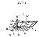
- FIG. 1is a cross sectional side view showing a blade block of a hair clipper in accordance with a first embodiment of the present invention
- FIGS. 2A and 2Bare views for explaining the movement of a comb shaped blade edge portion of a fixed blade when the blade block is in use;
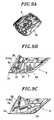
- FIGS. 3A , 3 B and 3 Care front, side and cross sectional side views of the hair clipper, respectively;
- FIGS. 4A to 4Eare perspective, front, plan, side and cross sectional side views of the blade block, respectively;
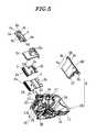
- FIG. 5is an exploded perspective view of the blade block
- FIG. 6Ais a perspective view of a blade holder employed in the hair clipper blade block shown in FIG. 1 ,
- FIGS. 6B and 6Care views for explaining the retaining operation performed by a primary retainer member
- FIG. 6Dis a view for explaining the retaining operation performed by a secondary retainer member
- FIGS. 7A and 7Bare views for explaining the manner in which a blade cover is retained by a blade cover attachment hook which prevents the removal of the blade cover;
- FIG. 8is an exploded perspective view of a hair clipper blade block in accordance with a second embodiment of the present invention.
- FIG. 9Ais a perspective view of a blade holder employed in the hair clipper blade block shown in FIG. 8 ;
- FIG. 9Bis a view for explaining the retaining operation performed by a primary retainer member in the second embodiment.
- FIG. 9Cis a view for explaining the retaining operation performed by a secondary retainer member in the second embodiment.
- a hair clipper 1 of the present inventionincludes a main body block 10 having a contour of a grip shape and a blade block 9 attached to a top portion of the main body block 10 .
- the main body block 10includes a housing 11 , a motor 12 accommodated in the housing 11 and a battery 40 accommodated in the housing 11 for supplying electric power to the motor 12 .
- a power transmitting mechanism 14 for transmitting drive force from the motor 12 to a movable blade 3is connected to a shaft of the motor 12 .
- a portion of the surface of the main body block 10forms a grip having a switch 13 .
- the switch 13By manipulating the switch 13 to be on, the electric power from the battery 40 is supplied to the motor 12 which in turn imparts reciprocating movement to the movable blade 3 through the power transmitting mechanism 14 , thereby cutting hairs.
- the blade block 9includes a comb-shaped fixed blade 2 ; the comb-shaped movable blade 3 arranged on the top surface of the fixed blade 2 ; a guide plate 15 through which the reciprocating movement of the power transmitting mechanism 14 of the main body block 10 is transmitted to the movable blade 3 ; a pressing spring 4 arranged on the top surface of the guide plate 15 for applying a pressing load to the movable blade 3 through the guide plate 15 ; and a blade base 5 for accommodating the fixed blade 2 , the movable blade 3 and the pressing spring 4 and the guide plate 15 .
- the movable blade 3makes reciprocating movement in a state that it is pressed against the fixed blade 2 by means of the pressing spring 4 , whereby the hairs lying between a comb-shaped blade edge portion 2 a of the fixed blade 2 and a comb-shaped blade edge portion 3 c of the movable blade 3 are cut.
- the blade base 5is divided into a blade holder 5 A, which holds the fixed blade 2 and the movable blade 3 , and a blade cover 5 B attached to the blade holder 5 A for covering the fixed blade 2 and the movable blade 3 , the blade holder 5 A and the blade cover 5 B being formed separately.
- the blade holder 5 Ais detachably attached to the main body block 10 by means of an attachment member.
- the attachment membermay be of the type having a plurality of elastic locking portions (designated by reference numeral 16 in FIG. 5 ) which are provided in an upper opening edge 17 of the blade holder 5 A and elastically engaged with a top protruding wall portion (not shown) of the main body block 10 .
- the blade holder 5 Amay be attached to the main body block 10 in place by fitting the upper opening edge 17 of the blade holder 5 A and the top abutting surface of the main body block 10 in a protrusion and recess fitting manner.
- the attachment member for the blade holder 5 Ais not limited to the above-described configurations but may be appropriately modified in design.
- the outer peripheral surface of the blade holder 5 Ahas a smooth skin contact surface 41 .
- the fixed blade 2 , the movable blade 3 , the guide plate 15 and the pressing spring 4are received within the blade holder 5 A.
- sidewall portions 19are formed at the left and the right end portion of a lower wall portion 18 of the blade holder 5 A.
- a blade cover attachment groove 21 and a blade cover attachment plate 22are provided at a front end portion 20 of each of the sidewall portions 19 .
- the blade cover attachment groove 21is formed at the upper half portion of the front end portion 20 and the blade cover attachment plate 22 is formed at the lower portion of the front end portion 20 .
- the blade cover attachment groove 21has a substantially “U” shaped cross section opened toward the blade cover attachment groove 21 at the opposite side.
- a front sidewall 21 a of the blade cover attachment groove 21runs substantially parallel to the front edge of the sidewall portion 19 , but a top portion of a rear side wall 21 b of the blade cover attachment groove 21 is bent backward.
- the blade cover attachment plate 22is integrally formed with the inner surface of each sidewall portion 19 of the blade holder 5 A and has a slit 23 and protruding portions 24 protruding into the slit 23 .
- the slitis extended along an attachment direction of the blade cover 5 B and opened in a forward, a backward and an upward direction.
- the blade cover attachment plate 22is arranged in such a position as not to block the rear sidewall 21 b of the blade cover attachment groove 21 .
- the lower portion of the front end portion 20 of the blade holder 5 Ais of an outwardly expanded shape and the blade cover attachment plate 22 is arranged inside the outwardly expanded portion in such a way that the blade cover attachment plate 22 does not block the rear sidewall 21 b of the blade cover attachment groove 21 .
- a front boss 25 to which a boss-hole 2 c of the fixed blade 2 fitted and securedis provided in the center portion of the lower wall portion 18 of the blade holder 5 A.
- a pair of left and right positioning ribs 26which is fitted into a rear cutout portion 2 b of the fixed blade 2 .
- the boss 25 and the positioning ribs 26form a fixing member for fixing the fixed blade 2 to the blade holder 5 A.
- the movable blade 3is mounted on top of the fixed blade 2 and the guide plate 15 is arranged on top of the movable blade 3 .
- the guide plate 15serves to transfer the reciprocating movement of the power transmitting mechanism 14 of the main body block 10 to the movable blade 3 .
- an engaging ribs 15 c with which the power transmitting mechanism 14 is engagedprotrude from the top surface of the guide plate 15 and a plurality of coupling lugs 15 a and 15 b (two front coupling lugs 15 a and one rear coupling lug 15 b in the present example) (see FIG. 1 ) is formed on the bottom surface of the guide plate 15 .
- the two front coupling lugs 15 aare fitted to two front holes 3 a of the movable blade 3 and the one rear coupling lug 15 b is fitted to a rear hole 3 b of the movable blade 3 .
- the pressing spring 4 for resiliently pressing the guide plate 15 against the movable blade 3is arranged on top of the guide plate 15 .
- the pressing spring 4includes a spring plate 4 a manufactured by cutting and press forming, e.g., a metal sheet by using a die.
- the pressing spring 4further includes a pair of elastic pressing pieces 4 c by cutting and erecting two longitudinally spaced apart regions of the generally rectangular spring plate 4 a ; a central crosspiece 4 b left intact between the longitudinally spaced apart regions; and boss-holes 4 d in the longitudinal opposite end portions of the spring plate 4 a .
- the pair of elastic pressing pieces 4 care bent downward to have a generally “V” shape with the vertex being omitted when seen from the front side.
- each of the two longitudinally spaced apart regionshas four edges and all edges excepting two longitudinally opposite edges of the two regions are cut from the spring plate 4 a and bent downward.
- two opposite end portions 4 e of the pressing spring 4are adapted to be retained in place by a primary retainer member 7 provided at the blade holder 5 A and a secondary retainer member 8 provided at the blade cover 5 B.
- the elastic pressing pieces 4 c of the pressing spring 4are elastically deformable in a direction perpendicular to the thickness direction of the spring plate 4 a .
- the blade holder 5 Ais provided with a pair of left and right spring rests 6 for respectively receiving the left and the right end portion 4 e of the pressing spring 4 .
- the spring rests 6are provided at the left and the right end portion of the lower wall portion 18 of the blade holder 5 A.
- a boss 7 a constituting a part of the primary retainer member 7protrudes from the central portion of each spring rest 6 .
- the end portions 4 e of the pressing spring 4are laid down on the spring rests 6 and the bosses 7 a are fitted to the boss-hole 4 d of the pressing spring 4 .
- the blade cover 5 Bhas a generally rectangular plate-like front portion 5 a and a rear portion 5 b with a wide breadth rear portion 5 c whose breadth is greater than that of the front portion 5 a .
- a fin portion 27protrudes from each flank side of the front portion 5 a of the blade cover 5 B so that it can be slidably fitted to the blade cover attachment groove 21 of the blade holder 5 A.
- a pair of left and right insertion pieces 28which can be inserted into the slits 23 of the blade cover attachment plate 22 , protrude from the two opposite end portions of the wide breadth rear portion 5 c of the blade cover 5 B in a backward direction of the blade cover 5 B.
- Lock portions 42protrude from the inner surfaces of the insertion pieces 28 .
- the lock portions 42ride over the protruding portions 24 projected into the slits 23 and to make hooking engagement with the protruding portions 24 . This keeps the insertion pieces 28 from being removed out of the slits 23 .
- the blade cover 5 Bincludes a secondary retainer member 8 for pressing the left and right end portions 4 e of the pressing spring 4 in a direction in which the pressing spring 4 is retained by the boss 7 a (the primary retainer means 7 ), i.e., in a direction toward the spring rests 6 of the blade holder 5 A or the movable blade 2 .
- a spring push surface 8 a constituting the secondary retainer member 8is formed at each of the left and right end portions of a rear surface of the blade cover 5 B. As shown in FIG.
- the spring push surfaces 8 aare of such a shape that, when the blade cover 5 B is attached to the blade holder 5 A, they can press the peripheral portions of the boss-holes 4 d formed at the end portions 4 e of the pressing spring 4 toward the spring rests 6 .
- Each spring push surface 8 acan be a flat surface of formed of one or more protrusions to be in touch with the end portion 4 e.
- the blade block 9 configured as aboveis assembled in the following manner. First, the fixed blade 2 , the movable blade 3 and the guide plate 15 are received and stacked on atop another in that sequence in the blade holder 5 A. In a state that the elastic pressing pieces 4 c of the pressing spring 4 face the top surface of the guide plate 15 , the boss-holes 4 d formed at the opposite end portions 4 e of the pressing spring 4 are fitted to the left and right bosses 7 a protruding from the opposite end portions of the lower wall portion 18 of the blade holder 5 A, thereby positioning the pressing spring 4 in the spring rests 6 ( FIG. 6B ).
- the blade cover 5 Bis attached to the blade holder 5 A.
- the fin portions 27 of the blade cover 5 Bare slidingly inserted into the blade cover attachment grooves 21 of the blade holder 5 A and, at the same time, the insertion pieces 28 of the wide breadth rear portion 5 c of the blade cover 5 B are inserted along the slits 23 of the blade cover attachment plate 22 of the blade holder 5 A in the direction indicated by an arrow “A” in FIG. 7A , whereby the insertion pieces 28 are locked by the blade cover attachment plate 22 against removal in the direction indicated by an arrow “B” in FIG. 7B .
- the spring push surfaces 8 a of the rear surface of the blade cover 5 Bcome into a state that they press the peripheral portions of the boss-holes 4 d of the pressing spring 4 toward the spring rests 6 (the state shown in FIG. 6D ).
- a transversely extending slot-like blade protruding hole 29(see FIG. 2 ) is formed at the front end corner portion of the blade base 5 and the comb-shaped blade edge portions 2 a and 3 c project outwardly from the inside of the blade base 5 through the blade protruding hole 29 .
- the pressing spring 4is retained in place by upsetting the exposed free end portion of the bosses 7 a (the primary retainer member 7 ) provided at the spring rests 6 of the blade holder 5 A.
- the pressing spring 4may possibly float or move upward while being hold by the bosses 7 a .
- the deformed bosses 7 amay undergo creep deformation even though the pressing spring 4 was fixedly held by the bosses 7 a at the beginning, resulting in the floating of the pressing spring 4 as well.
- the spring push surfaces 8 a(the secondary retainer member 8 ) as well as the primary retainer member 7 are provided in the blade cover 5 B formed independently of the blade holder 5 A so that, when the blade cover 5 B is attached to the blade holder 5 A, the spring push surfaces 8 a can provide an effect of pushing down the pressing spring 4 . This makes it possible to reliably retain the opposite end portions 4 e of the pressing spring 4 not to move upward.
- the retaining force of the pressing spring 4is increased by the double retaining structure offered by the primary retainer member 7 and the secondary retainer member 8 . Therefore, even when the comb-shaped blade edge portion 2 a is bent in parallel with the skin contact surface 41 as shown in FIG. 2A or bent upwardly from the skin contact surface 41 as indicated by an arrow in FIG. 2B , the pressing force applied to the movable blade 3 by the pressing spring 4 can be kept high enough to stably apply a pressing load to the movable blade 3 against the fixed blade 2 . As a result, it becomes possible to obtain the blade block 9 that can improve the cutting performance of the hair clipper and is strong, robust and durable even in unfriendly environment.
- the insertion pieces 28 with the lock portions 42 provided at the wide breadth rear portion 5 c of the blade cover 5 Bare locked to the blade cover attachment plate 22 of the blade holder 5 A in a removal-proof manner merely by slidingly fitting the fin portions 27 formed at the front portion of the blade cover 5 B to the blade cover attachment grooves 21 of the blade holder 5 A. Accordingly, the task of attaching the blade cover 5 B to the blade holder 5 A becomes quite simple and reliable, thus providing an advantage in that the assembly works can be done in a relatively easy manner.
- FIGS. 8 and 9illustrate another embodiment of the present invention.
- wing plate portions 30 serving as the primary retainer member 7protrude from the lower surfaces of the opposite end portions 4 e of the pressing spring 4 toward the lower wall portion 18 of the blade holder 5 A.
- a fixing hole 31 opened in a transverse directionis formed through each of the wing plate portions 30 .
- Engaging lugs 32protrude in a transverse direction from the inner side surfaces of the left and right spring rests 6 provided at the left and right end portions of the lower wall portion 18 of the blade holder 5 A.
- the secondary retainer member 8is of a structure pushing the pressing spring 4 toward the spring rests 6 by the spring push surfaces 8 a provided at the blade cover 5 B. Corresponding parts to the preceding embodiment are designated by like reference characters and no detailed description will be made in that regard.
- the opposite end portions 4 e of the pressing spring 4can be kept from floating upwardly from the spring rests 6 , merely by placing the opposite end portions 4 e of the pressing spring 4 on the upper surfaces of the spring rests 6 and interlocking the fixing holes 31 of the wing plate portions 30 and the engaging lugs 32 protruding from the inner side surfaces of the spring rests 6 . Consequently, use of the primary retainer member 7 of the second embodiment makes it possible to omit the upsetting process of the exposed free end portion of the bosses 7 a (see FIG. 6B ) required in the preceding embodiment, which provides an advantage of simplifying the assembly works.
Landscapes
- Life Sciences & Earth Sciences (AREA)
- Forests & Forestry (AREA)
- Engineering & Computer Science (AREA)
- Mechanical Engineering (AREA)
- Dry Shavers And Clippers (AREA)
Abstract
Description
Claims (7)
Applications Claiming Priority (2)
| Application Number | Priority Date | Filing Date | Title |
|---|---|---|---|
| JP2006333627AJP4251213B2 (en) | 2006-12-11 | 2006-12-11 | Hair clipper blade block |
| JP2006-333627 | 2006-12-11 |
Publications (2)
| Publication Number | Publication Date |
|---|---|
| US20080134516A1 US20080134516A1 (en) | 2008-06-12 |
| US8024862B2true US8024862B2 (en) | 2011-09-27 |
Family
ID=39146923
Family Applications (1)
| Application Number | Title | Priority Date | Filing Date |
|---|---|---|---|
| US11/987,941Active2030-01-26US8024862B2 (en) | 2006-12-11 | 2007-12-06 | Hair clipper |
Country Status (6)
| Country | Link |
|---|---|
| US (1) | US8024862B2 (en) |
| EP (1) | EP1932633B1 (en) |
| JP (1) | JP4251213B2 (en) |
| CN (2) | CN100588515C (en) |
| AT (1) | ATE461018T1 (en) |
| DE (1) | DE602007005333D1 (en) |
Cited By (8)
| Publication number | Priority date | Publication date | Assignee | Title |
|---|---|---|---|---|
| USD711595S1 (en) | 2013-05-03 | 2014-08-19 | Daryl Walker | Hair clipper holding sleeve |
| USD794871S1 (en) | 2016-01-15 | 2017-08-15 | Medline Industries, Inc. | Clipper |
| USD795497S1 (en) | 2016-01-15 | 2017-08-22 | Medline Industries, Inc. | Clipper |
| USD802214S1 (en) | 2016-06-10 | 2017-11-07 | Medline Industries, Inc. | Clipper head |
| USD802215S1 (en) | 2016-06-10 | 2017-11-07 | Medline Industries, Inc. | Clipper head |
| USD802216S1 (en) | 2016-06-10 | 2017-11-07 | Medline Industries, Inc. | Clipper head |
| USD802217S1 (en) | 2016-06-10 | 2017-11-07 | Medline Industries, Inc. | Clipper head |
| US11510471B2 (en) | 2020-02-18 | 2022-11-29 | Spectrum Brands, Inc. | Hair dryer assembly having hair receiving channel |
Families Citing this family (13)
| Publication number | Priority date | Publication date | Assignee | Title |
|---|---|---|---|---|
| JP4251213B2 (en)* | 2006-12-11 | 2009-04-08 | パナソニック電工株式会社 | Hair clipper blade block |
| JP4735531B2 (en)* | 2006-12-22 | 2011-07-27 | パナソニック電工株式会社 | Hair clipper |
| FR2939065A1 (en)* | 2008-12-02 | 2010-06-04 | Jean Marc Brun | Electric mower, has detachable shearing head with rocker valve for positioning and interlocking removable head of shearing, and positioning piece formed by base and two lateral guiding ears for positioning and fixing head |
| PL2614938T3 (en) | 2012-01-12 | 2020-06-29 | Spectrum Brands, Inc. | Electric hair trimmer |
| CN102990683B (en)* | 2012-12-18 | 2015-02-11 | 珠海新秀丽家居用品有限公司 | Clipper with locking device and detachable clipper head |
| USD711594S1 (en) | 2013-02-22 | 2014-08-19 | Medline Industries, Inc. | Clipper head |
| USD692376S1 (en) | 2013-02-22 | 2013-10-29 | Medline Industries, Inc. | Clipper charging base |
| USD711044S1 (en) | 2013-02-22 | 2014-08-12 | Medline Industries, Inc. | Clipper |
| USD711593S1 (en) | 2013-02-22 | 2014-08-19 | Medline Industries, Inc. | Clipper head |
| USD711045S1 (en) | 2013-02-25 | 2014-08-12 | Medline Industries, Inc. | Clipper head |
| US9713877B2 (en) | 2014-11-12 | 2017-07-25 | Medline Industries, Inc. | Clipper head with drag reduction |
| USD779123S1 (en) | 2014-11-12 | 2017-02-14 | Medline Industries, Inc. | Clipper head |
| EP3381629A1 (en) | 2017-03-28 | 2018-10-03 | Koninklijke Philips N.V. | Comb arrangement, cutting head, and hair cutting appliance |
Citations (46)
| Publication number | Priority date | Publication date | Assignee | Title |
|---|---|---|---|---|
| US3052025A (en)* | 1961-06-23 | 1962-09-04 | Donald D Ring | Tension adjuster for clipper heads |
| US3561116A (en)* | 1969-10-15 | 1971-02-09 | Wahl Clipper Corp | Transmission members for electric hair clipper |
| US3747212A (en)* | 1970-09-09 | 1973-07-24 | Aesculap Werke Ag | Cutterhead unit for hair clipper |
| NL7404738A (en) | 1974-04-08 | 1975-10-10 | Philips Nv | ELECTRIC HAIR CLIPPER. |
| US3992778A (en)* | 1975-04-28 | 1976-11-23 | Andis Clipper Company | Electric clipper |
| US4249307A (en)* | 1978-06-19 | 1981-02-10 | Andis Company | Hair clipper |
| US4328616A (en)* | 1978-06-19 | 1982-05-11 | Outboard Marine Corporation | Laminated hair clipper blade set |
| GB2113596A (en) | 1982-01-26 | 1983-08-10 | Matsushita Electric Works Ltd | Electric shaver |
| US4458417A (en) | 1982-07-26 | 1984-07-10 | Andis Company | Hair clipper blade set |
| JPH021078A (en) | 1988-10-07 | 1990-01-05 | Fuji Photo Film Co Ltd | Treatment of radiation picture and device for treating radiation picture |
| US5088200A (en)* | 1990-10-11 | 1992-02-18 | Andis Company | Hair trimmer having a low-friction rotary drive |
| US5325590A (en)* | 1993-03-09 | 1994-07-05 | Andis Company | Hair trimmer having a low-friction rotary drive |
| JPH06190158A (en)* | 1992-12-28 | 1994-07-12 | Matsushita Electric Works Ltd | Electric hair clipper |
| JPH06285272A (en)* | 1993-03-31 | 1994-10-11 | Matsushita Electric Works Ltd | Shaver |
| US5504997A (en)* | 1994-10-18 | 1996-04-09 | Lee; Ming H. | Blade holder assembly for an electric razor |
| US5544415A (en)* | 1994-12-06 | 1996-08-13 | Kunnex Incorporated | Water-proof and washable electric razor |
| JPH10235036A (en) | 1997-02-28 | 1998-09-08 | Sanyo Electric Co Ltd | Electric shaver |
| JP2001204979A (en)* | 2000-01-26 | 2001-07-31 | Matsushita Electric Works Ltd | Blade block of hair cutter |
| US6308415B1 (en)* | 1997-04-24 | 2001-10-30 | U.S. Philips Corporation | Hair-cutting apparatus having a toothed cutting device, and toothed cutting device for a hair-cutting apparatus |
| US6393702B1 (en)* | 1998-12-29 | 2002-05-28 | Kim Laube | Disposable cutting head for clippers |
| US6421922B2 (en)* | 1998-12-21 | 2002-07-23 | Braun Gmbh | Power driven hair clipper |
| US20030005585A1 (en)* | 2001-04-09 | 2003-01-09 | Conair Cip, Inc., | Detachable and adjustable blade assembly |
| US20050011076A1 (en)* | 2003-07-17 | 2005-01-20 | Andis Company | Ceramic movable blades for blade sets of hair clippers |
| US6862810B2 (en)* | 2002-06-21 | 2005-03-08 | Andis Company | Hair-trimmer with releasable cutting head |
| US6886255B2 (en)* | 2002-09-17 | 2005-05-03 | Wahl Clipper Corporation | Fixed head clipper and disposable blade assembly |
| US6895673B2 (en)* | 2001-09-17 | 2005-05-24 | Tae Jun O | Hair clipper having oil pad |
| US6901664B2 (en)* | 2002-07-18 | 2005-06-07 | Wahl Clipper Corporation | Hair clipper and seal |
| US6935029B2 (en)* | 2002-06-17 | 2005-08-30 | Matsushita Electric Works, Ltd. | Dry shaver with a trimmer |
| JP2005261486A (en)* | 2004-03-16 | 2005-09-29 | Matsushita Electric Works Ltd | Hair clipper |
| US20060042096A1 (en)* | 2004-09-01 | 2006-03-02 | Jeng Shyuan Precision Co., Ltd. | Cutter assembly for hair clipper |
| US20060230621A1 (en)* | 2005-04-15 | 2006-10-19 | Jeng Shyuan Precision Co., Ltd. | Cutter assembly for hair clipper |
| US20070044604A1 (en)* | 2005-08-30 | 2007-03-01 | Andis Company | Hair clipper with blade assembly release |
| JP2007209612A (en) | 2006-02-10 | 2007-08-23 | Kyushu Hitachi Maxell Ltd | Shear blade unit |
| EP1867446A1 (en)* | 2006-06-16 | 2007-12-19 | Matsushita Electric Works, Ltd. | Hair clipper |
| US7340839B2 (en)* | 2006-02-21 | 2008-03-11 | Tae-Jun Oh | Hair clipper having moving lower blade |
| EP1932633A1 (en)* | 2006-12-11 | 2008-06-18 | Matsushita Electric Works, Ltd. | Hair clipper |
| EP1935586A1 (en)* | 2006-12-22 | 2008-06-25 | Matsushita Electric Works, Ltd. | Hair Clipper |
| US20080168661A1 (en)* | 2007-01-14 | 2008-07-17 | Specialife Industries Limited | Blade set for hair clipper |
| US20080282550A1 (en)* | 2008-06-30 | 2008-11-20 | Andis Company | Blade assembly |
| EP2030743A1 (en)* | 2007-08-28 | 2009-03-04 | Panasonic Electric Works Co., Ltd. | Hair-clipper |
| US20090144988A1 (en)* | 2007-12-11 | 2009-06-11 | Specialife Industries Limited | blade driving assembly for an adjustable hair clipper |
| US7624506B2 (en)* | 2004-09-28 | 2009-12-01 | Wahl Clipper Corporation | Driving member for hair cutting device with replaceable tip |
| US20090320296A1 (en)* | 2008-06-25 | 2009-12-31 | Panasonic Electric Works, Co., Ltd. | Hair trimmer blade unit |
| US20100000093A1 (en)* | 2008-07-07 | 2010-01-07 | Kingdom International Co., Ltd. | Hair clipper blade assembly |
| US7748123B2 (en)* | 2006-08-31 | 2010-07-06 | Rovcal, Inc. | Electric hair cutting appliance with counter weight |
| JP2010213832A (en)* | 2009-03-16 | 2010-09-30 | Panasonic Electric Works Co Ltd | Hair removing gear |
- 2006
- 2006-12-11JPJP2006333627Apatent/JP4251213B2/ennot_activeExpired - Fee Related
- 2007
- 2007-12-05ATAT07023565Tpatent/ATE461018T1/ennot_activeIP Right Cessation
- 2007-12-05DEDE602007005333Tpatent/DE602007005333D1/enactiveActive
- 2007-12-05EPEP07023565Apatent/EP1932633B1/ennot_activeNot-in-force
- 2007-12-06USUS11/987,941patent/US8024862B2/enactiveActive
- 2007-12-10CNCN200710199502Apatent/CN100588515C/ennot_activeExpired - Fee Related
- 2007-12-10CNCNU2007201820291Upatent/CN201195316Y/ennot_activeExpired - Lifetime
Patent Citations (59)
| Publication number | Priority date | Publication date | Assignee | Title |
|---|---|---|---|---|
| US3052025A (en)* | 1961-06-23 | 1962-09-04 | Donald D Ring | Tension adjuster for clipper heads |
| US3561116A (en)* | 1969-10-15 | 1971-02-09 | Wahl Clipper Corp | Transmission members for electric hair clipper |
| US3747212A (en)* | 1970-09-09 | 1973-07-24 | Aesculap Werke Ag | Cutterhead unit for hair clipper |
| NL7404738A (en) | 1974-04-08 | 1975-10-10 | Philips Nv | ELECTRIC HAIR CLIPPER. |
| US3962785A (en) | 1974-04-08 | 1976-06-15 | U.S. Philips Corporation | Electric trimmer |
| US3992778A (en)* | 1975-04-28 | 1976-11-23 | Andis Clipper Company | Electric clipper |
| US4249307A (en)* | 1978-06-19 | 1981-02-10 | Andis Company | Hair clipper |
| US4328616A (en)* | 1978-06-19 | 1982-05-11 | Outboard Marine Corporation | Laminated hair clipper blade set |
| GB2113596A (en) | 1982-01-26 | 1983-08-10 | Matsushita Electric Works Ltd | Electric shaver |
| US4512077A (en) | 1982-01-26 | 1985-04-23 | Matsushita Electric Works, Ltd. | Electric shaver having improved shaving characteristics |
| US4458417A (en) | 1982-07-26 | 1984-07-10 | Andis Company | Hair clipper blade set |
| JPH021078A (en) | 1988-10-07 | 1990-01-05 | Fuji Photo Film Co Ltd | Treatment of radiation picture and device for treating radiation picture |
| US5088200A (en)* | 1990-10-11 | 1992-02-18 | Andis Company | Hair trimmer having a low-friction rotary drive |
| JPH06190158A (en)* | 1992-12-28 | 1994-07-12 | Matsushita Electric Works Ltd | Electric hair clipper |
| US5325590A (en)* | 1993-03-09 | 1994-07-05 | Andis Company | Hair trimmer having a low-friction rotary drive |
| JPH06285272A (en)* | 1993-03-31 | 1994-10-11 | Matsushita Electric Works Ltd | Shaver |
| US5504997A (en)* | 1994-10-18 | 1996-04-09 | Lee; Ming H. | Blade holder assembly for an electric razor |
| US5544415A (en)* | 1994-12-06 | 1996-08-13 | Kunnex Incorporated | Water-proof and washable electric razor |
| JPH10235036A (en) | 1997-02-28 | 1998-09-08 | Sanyo Electric Co Ltd | Electric shaver |
| US6308415B1 (en)* | 1997-04-24 | 2001-10-30 | U.S. Philips Corporation | Hair-cutting apparatus having a toothed cutting device, and toothed cutting device for a hair-cutting apparatus |
| US6421922B2 (en)* | 1998-12-21 | 2002-07-23 | Braun Gmbh | Power driven hair clipper |
| US6473973B2 (en)* | 1998-12-29 | 2002-11-05 | Kim Laube | Disposable cutting head for clippers |
| US7010859B2 (en)* | 1998-12-29 | 2006-03-14 | Kim Laube | Disposable cutting head for clippers |
| US6393702B1 (en)* | 1998-12-29 | 2002-05-28 | Kim Laube | Disposable cutting head for clippers |
| EP1120206A1 (en)* | 2000-01-26 | 2001-08-01 | Matsushita Electric Works, Ltd. | A blade block of a hair cutter |
| US6490798B2 (en)* | 2000-01-26 | 2002-12-10 | Matsushita Electric Works, Ltd. | Blade block of a hair cutter |
| JP2001204979A (en)* | 2000-01-26 | 2001-07-31 | Matsushita Electric Works Ltd | Blade block of hair cutter |
| US20030005585A1 (en)* | 2001-04-09 | 2003-01-09 | Conair Cip, Inc., | Detachable and adjustable blade assembly |
| US6895673B2 (en)* | 2001-09-17 | 2005-05-24 | Tae Jun O | Hair clipper having oil pad |
| US6935029B2 (en)* | 2002-06-17 | 2005-08-30 | Matsushita Electric Works, Ltd. | Dry shaver with a trimmer |
| US6862810B2 (en)* | 2002-06-21 | 2005-03-08 | Andis Company | Hair-trimmer with releasable cutting head |
| US6901664B2 (en)* | 2002-07-18 | 2005-06-07 | Wahl Clipper Corporation | Hair clipper and seal |
| US6886255B2 (en)* | 2002-09-17 | 2005-05-03 | Wahl Clipper Corporation | Fixed head clipper and disposable blade assembly |
| US20050011076A1 (en)* | 2003-07-17 | 2005-01-20 | Andis Company | Ceramic movable blades for blade sets of hair clippers |
| US7080458B2 (en)* | 2003-07-17 | 2006-07-25 | Andis Company | Ceramic movable blades for blade sets of hair clippers |
| JP2005261486A (en)* | 2004-03-16 | 2005-09-29 | Matsushita Electric Works Ltd | Hair clipper |
| US20060042096A1 (en)* | 2004-09-01 | 2006-03-02 | Jeng Shyuan Precision Co., Ltd. | Cutter assembly for hair clipper |
| US7624506B2 (en)* | 2004-09-28 | 2009-12-01 | Wahl Clipper Corporation | Driving member for hair cutting device with replaceable tip |
| US20060230621A1 (en)* | 2005-04-15 | 2006-10-19 | Jeng Shyuan Precision Co., Ltd. | Cutter assembly for hair clipper |
| US20070044604A1 (en)* | 2005-08-30 | 2007-03-01 | Andis Company | Hair clipper with blade assembly release |
| JP2007209612A (en) | 2006-02-10 | 2007-08-23 | Kyushu Hitachi Maxell Ltd | Shear blade unit |
| US7340839B2 (en)* | 2006-02-21 | 2008-03-11 | Tae-Jun Oh | Hair clipper having moving lower blade |
| EP1867446A1 (en)* | 2006-06-16 | 2007-12-19 | Matsushita Electric Works, Ltd. | Hair clipper |
| US20070289144A1 (en)* | 2006-06-16 | 2007-12-20 | Matsushita Electric Works, Ltd. | Hair clipper |
| US7748123B2 (en)* | 2006-08-31 | 2010-07-06 | Rovcal, Inc. | Electric hair cutting appliance with counter weight |
| JP2008142344A (en)* | 2006-12-11 | 2008-06-26 | Matsushita Electric Works Ltd | Blade block of hair clipper |
| EP1932633A1 (en)* | 2006-12-11 | 2008-06-18 | Matsushita Electric Works, Ltd. | Hair clipper |
| US7762001B2 (en)* | 2006-12-22 | 2010-07-27 | Panasonic Electric Works Co., Ltd. | Hair clipper |
| JP2008154765A (en)* | 2006-12-22 | 2008-07-10 | Matsushita Electric Works Ltd | Hair clipper |
| EP1935586A1 (en)* | 2006-12-22 | 2008-06-25 | Matsushita Electric Works, Ltd. | Hair Clipper |
| US20080168661A1 (en)* | 2007-01-14 | 2008-07-17 | Specialife Industries Limited | Blade set for hair clipper |
| EP2030743A1 (en)* | 2007-08-28 | 2009-03-04 | Panasonic Electric Works Co., Ltd. | Hair-clipper |
| US20090056143A1 (en)* | 2007-08-28 | 2009-03-05 | Matsushita Electric Works, Ltd. | Hair-clipper |
| JP2009050496A (en)* | 2007-08-28 | 2009-03-12 | Panasonic Electric Works Co Ltd | Clippers |
| US20090144988A1 (en)* | 2007-12-11 | 2009-06-11 | Specialife Industries Limited | blade driving assembly for an adjustable hair clipper |
| US20090320296A1 (en)* | 2008-06-25 | 2009-12-31 | Panasonic Electric Works, Co., Ltd. | Hair trimmer blade unit |
| US20080282550A1 (en)* | 2008-06-30 | 2008-11-20 | Andis Company | Blade assembly |
| US20100000093A1 (en)* | 2008-07-07 | 2010-01-07 | Kingdom International Co., Ltd. | Hair clipper blade assembly |
| JP2010213832A (en)* | 2009-03-16 | 2010-09-30 | Panasonic Electric Works Co Ltd | Hair removing gear |
Cited By (11)
| Publication number | Priority date | Publication date | Assignee | Title |
|---|---|---|---|---|
| USD711595S1 (en) | 2013-05-03 | 2014-08-19 | Daryl Walker | Hair clipper holding sleeve |
| USD794871S1 (en) | 2016-01-15 | 2017-08-15 | Medline Industries, Inc. | Clipper |
| USD795497S1 (en) | 2016-01-15 | 2017-08-22 | Medline Industries, Inc. | Clipper |
| USD848073S1 (en) | 2016-01-15 | 2019-05-07 | Medline Industries, Inc. | Clipper |
| USD802214S1 (en) | 2016-06-10 | 2017-11-07 | Medline Industries, Inc. | Clipper head |
| USD802215S1 (en) | 2016-06-10 | 2017-11-07 | Medline Industries, Inc. | Clipper head |
| USD802216S1 (en) | 2016-06-10 | 2017-11-07 | Medline Industries, Inc. | Clipper head |
| USD802217S1 (en) | 2016-06-10 | 2017-11-07 | Medline Industries, Inc. | Clipper head |
| US11510471B2 (en) | 2020-02-18 | 2022-11-29 | Spectrum Brands, Inc. | Hair dryer assembly having hair receiving channel |
| US11871827B2 (en) | 2020-02-18 | 2024-01-16 | Spectrum Brands, Inc. | Hair dryer assembly having hair receiving channel |
| US12156578B2 (en) | 2020-02-18 | 2024-12-03 | Spectrum Brands, Inc. | Hair dryer assembly having hair receiving channel |
Also Published As
| Publication number | Publication date |
|---|---|
| JP2008142344A (en) | 2008-06-26 |
| EP1932633B1 (en) | 2010-03-17 |
| CN201195316Y (en) | 2009-02-18 |
| DE602007005333D1 (en) | 2010-04-29 |
| JP4251213B2 (en) | 2009-04-08 |
| US20080134516A1 (en) | 2008-06-12 |
| EP1932633A1 (en) | 2008-06-18 |
| CN100588515C (en) | 2010-02-10 |
| ATE461018T1 (en) | 2010-04-15 |
| CN101200072A (en) | 2008-06-18 |
Similar Documents
| Publication | Publication Date | Title |
|---|---|---|
| US8024862B2 (en) | Hair clipper | |
| US10919166B2 (en) | Shaving blade cartridge | |
| CN107639654B (en) | Cutting tool | |
| JP7457461B2 (en) | Razor Cartridge | |
| JP6027294B1 (en) | Hair cutting device, container and connecting plug | |
| RU2519338C1 (en) | Combined device for shaving and trimming | |
| US10632635B2 (en) | Razor | |
| US10093030B2 (en) | Shaving blade cartridge | |
| US20050016002A1 (en) | Electric shaver | |
| JP5260199B2 (en) | Compact container | |
| JP2709283B2 (en) | IC carrier | |
| EP3878615A1 (en) | Interconnecting member and handle for shaver | |
| CN112388680A (en) | Razor blade | |
| EP2530696A1 (en) | Electromagnetic contactor, detachable structure for auxiliary unit, and assembly method for movable hook section provided on auxiliary unit | |
| JP2002052503A (en) | Shoe-fixing device of reciprocative cutting tool | |
| JP2012090860A (en) | Retractable knife | |
| JP4863271B2 (en) | Electric razor | |
| JP5415213B2 (en) | Knife | |
| US12040600B2 (en) | Fixture mounting structure and resin fixture | |
| JPS62148687A (en) | Hair clippers | |
| WO2021026676A1 (en) | Shaver and interconnecting component thereof | |
| JP4508713B2 (en) | Electric razor | |
| JPH0625202Y2 (en) | Hair stopper | |
| JP5241389B2 (en) | Compact container | |
| JPS5811347Y2 (en) | safety razor |
Legal Events
| Date | Code | Title | Description |
|---|---|---|---|
| AS | Assignment | Owner name:MATSUSHITA ELECTRIC WORKS, LTD., JAPAN Free format text:ASSIGNMENT OF ASSIGNORS INTEREST;ASSIGNORS:MORISUGI, KAZUHIRO;IKUTA, TOSHIO;REEL/FRAME:020247/0842 Effective date:20071025 | |
| AS | Assignment | Owner name:PANASONIC ELECTRIC WORKS CO., LTD., JAPAN Free format text:CHANGE OF NAME;ASSIGNOR:MATSUSHITA ELECTRIC WORKS, LTD.;REEL/FRAME:022206/0574 Effective date:20081001 Owner name:PANASONIC ELECTRIC WORKS CO., LTD.,JAPAN Free format text:CHANGE OF NAME;ASSIGNOR:MATSUSHITA ELECTRIC WORKS, LTD.;REEL/FRAME:022206/0574 Effective date:20081001 | |
| STCF | Information on status: patent grant | Free format text:PATENTED CASE | |
| FEPP | Fee payment procedure | Free format text:PAYOR NUMBER ASSIGNED (ORIGINAL EVENT CODE: ASPN); ENTITY STATUS OF PATENT OWNER: LARGE ENTITY | |
| FPAY | Fee payment | Year of fee payment:4 | |
| MAFP | Maintenance fee payment | Free format text:PAYMENT OF MAINTENANCE FEE, 8TH YEAR, LARGE ENTITY (ORIGINAL EVENT CODE: M1552); ENTITY STATUS OF PATENT OWNER: LARGE ENTITY Year of fee payment:8 | |
| MAFP | Maintenance fee payment | Free format text:PAYMENT OF MAINTENANCE FEE, 12TH YEAR, LARGE ENTITY (ORIGINAL EVENT CODE: M1553); ENTITY STATUS OF PATENT OWNER: LARGE ENTITY Year of fee payment:12 |