US8022887B1 - Planar antenna - Google Patents
Planar antennaDownload PDFInfo
- Publication number
- US8022887B1 US8022887B1US11/588,472US58847206AUS8022887B1US 8022887 B1US8022887 B1US 8022887B1US 58847206 AUS58847206 AUS 58847206AUS 8022887 B1US8022887 B1US 8022887B1
- Authority
- US
- United States
- Prior art keywords
- planar antenna
- antenna
- substrate
- driver
- coupled
- Prior art date
- Legal status (The legal status is an assumption and is not a legal conclusion. Google has not performed a legal analysis and makes no representation as to the accuracy of the status listed.)
- Active
Links
- 239000000758substrateSubstances0.000claimsdescription22
- 238000004891communicationMethods0.000description30
- 238000012546transferMethods0.000description22
- 230000005540biological transmissionEffects0.000description11
- 230000003044adaptive effectEffects0.000description10
- 238000012549trainingMethods0.000description7
- 238000010586diagramMethods0.000description6
- 238000012545processingMethods0.000description5
- 238000000034methodMethods0.000description4
- 230000008901benefitEffects0.000description3
- 238000012512characterization methodMethods0.000description3
- 235000019800disodium phosphateNutrition0.000description3
- 238000004519manufacturing processMethods0.000description3
- 230000008859changeEffects0.000description2
- 239000000463materialSubstances0.000description2
- 238000005259measurementMethods0.000description2
- 238000012986modificationMethods0.000description2
- 230000004048modificationEffects0.000description2
- 230000008569processEffects0.000description2
- 230000007704transitionEffects0.000description2
- PNEYBMLMFCGWSK-UHFFFAOYSA-Naluminium oxideInorganic materials[O-2].[O-2].[O-2].[Al+3].[Al+3]PNEYBMLMFCGWSK-UHFFFAOYSA-N0.000description1
- 238000013459approachMethods0.000description1
- 238000003491arrayMethods0.000description1
- 230000009286beneficial effectEffects0.000description1
- 239000002131composite materialSubstances0.000description1
- 230000008878couplingEffects0.000description1
- 238000010168coupling processMethods0.000description1
- 238000005859coupling reactionMethods0.000description1
- 230000002452interceptive effectEffects0.000description1
- 239000011159matrix materialSubstances0.000description1
- 230000003071parasitic effectEffects0.000description1
- 230000002093peripheral effectEffects0.000description1
- 230000005855radiationEffects0.000description1
- 230000004044responseEffects0.000description1
- 238000003756stirringMethods0.000description1
- 238000012360testing methodMethods0.000description1
Images


Classifications
- H—ELECTRICITY
- H01—ELECTRIC ELEMENTS
- H01Q—ANTENNAS, i.e. RADIO AERIALS
- H01Q19/00—Combinations of primary active antenna elements and units with secondary devices, e.g. with quasi-optical devices, for giving the antenna a desired directional characteristic
- H01Q19/22—Combinations of primary active antenna elements and units with secondary devices, e.g. with quasi-optical devices, for giving the antenna a desired directional characteristic using a secondary device in the form of a single substantially straight conductive element
- H—ELECTRICITY
- H01—ELECTRIC ELEMENTS
- H01Q—ANTENNAS, i.e. RADIO AERIALS
- H01Q1/00—Details of, or arrangements associated with, antennas
- H01Q1/36—Structural form of radiating elements, e.g. cone, spiral, umbrella; Particular materials used therewith
- H01Q1/38—Structural form of radiating elements, e.g. cone, spiral, umbrella; Particular materials used therewith formed by a conductive layer on an insulating support
- H—ELECTRICITY
- H01—ELECTRIC ELEMENTS
- H01Q—ANTENNAS, i.e. RADIO AERIALS
- H01Q21/00—Antenna arrays or systems
- H01Q21/06—Arrays of individually energised antenna units similarly polarised and spaced apart
- H01Q21/061—Two dimensional planar arrays
- H01Q21/062—Two dimensional planar arrays using dipole aerials
- H—ELECTRICITY
- H01—ELECTRIC ELEMENTS
- H01Q—ANTENNAS, i.e. RADIO AERIALS
- H01Q3/00—Arrangements for changing or varying the orientation or the shape of the directional pattern of the waves radiated from an antenna or antenna system
- H01Q3/26—Arrangements for changing or varying the orientation or the shape of the directional pattern of the waves radiated from an antenna or antenna system varying the relative phase or relative amplitude of energisation between two or more active radiating elements; varying the distribution of energy across a radiating aperture
- H—ELECTRICITY
- H01—ELECTRIC ELEMENTS
- H01Q—ANTENNAS, i.e. RADIO AERIALS
- H01Q9/00—Electrically-short antennas having dimensions not more than twice the operating wavelength and consisting of conductive active radiating elements
- H01Q9/04—Resonant antennas
- H01Q9/16—Resonant antennas with feed intermediate between the extremities of the antenna, e.g. centre-fed dipole
- H01Q9/28—Conical, cylindrical, cage, strip, gauze, or like elements having an extended radiating surface; Elements comprising two conical surfaces having collinear axes and adjacent apices and fed by two-conductor transmission lines
- H01Q9/285—Planar dipole
Definitions
- the present inventionrelates to a device for receiving/transmitting electromagnetic waves with high efficiency and low VSWR over a broad bandwidth that can be used most particularly in the field of wireless transmissions.
- Highly efficient planar radiating elementscan have various applications. They can be used as the radiating elements on an array, particularly of electronically steered type. In cases where high gain radiators are required, they can be used as the feeding element of a non-array antenna such as a horn or reflector antenna to avoid considerable feed losses, e.g. such as in mm-wave. Millimeter- and submillimeter-wave devices often utilize integrated circuits combined with waveguide components. This requires transitions between waveguides and different planar transmission lines. In addition, transitions to waveguide measurement systems are often needed for device characterization and testing. Efficient planar radiating elements can be tuned for such applications.
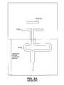
- FIG. 1illustrates the planar antenna.
- the structureutilizes a two-layer configuration that is a drawback in terms of manufacturing. Furthermore, the VSWR is not very low and the gain is not high.
- FIGS. 2A and 2BAnother prior art antenna, depicted in FIGS. 2A and 2B , is the uniplanar Yagi-like type, which consists of two dipole elements, a truncated ground plane and a microstrip-to-coplanar strips (hereinafter the term “coplanar strips” is abbreviated “CPS”) balun.
- the two dipole elementsinclude a director and a driver.
- the director and driver of the antennaare placed on the same plane of the substrate so that the surface waves generated by the antenna are directed to the end-fire direction.
- the antennacomprises a driver comprising a folded dipole and an integral balun coupled to the folded dipole.
- FIG. 1illustrates a planar antenna of the prior art
- FIGS. 2A and 2Bdepict top and isometric views of another prior art planar antenna, respectively;
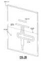
- FIGS. 3A , 3 B, 3 C, and 3 Dillustrate top and isometric views of an improved planar antenna according to one embodiment of the present invention, respectively.
- FIG. 3Billustrates a microstrip line feeding structure while
- FIG. 3Cillustrates a coplanar waveguide feeding structure according to one embodiment of the invention.
- FIG. 3Dillustrates a truncated ground which is serrated;
- FIG. 4is a block diagram of one embodiment of a communication system
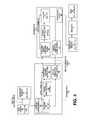
- FIG. 5is a more detailed block diagram of one embodiment of the communication system.
- FIG. 6is a block diagram of one embodiment of a peripheral device.
- the radiating elementcomprises a folded-dipole as the main driver, one or more directors, and a balanced feeding structure that is amenable to miniaturization and has a low VSWR.
- the folded dipoleis a directly fed element, i.e. driver, in a Yagi-like planar antenna.
- embodiments of the present inventionprovide an improved radiating element for use as the feeding element of another antenna.
- the radiating elementmay be used in an array and may be may be fabricated using printed circuit techniques.
- FIGS. 3A and 3Billustrate top and isometric views an improved planar antenna according to one embodiment of the present invention, respectively.
- a folded dipole 301operates as the driver, or main radiating portion, of a Yagi-like planar antenna.
- folded dipole 301is coupled to balun 302 via coplanar strips 304 .
- the structureis a quasi-Yagi with its balun in combination with a folded dipole.
- electromagnetic energyis coupled from folded dipole 301 through space into the parasitic dipoles and then reradiated to form a directional beam.
- folded dipole 301 and balun 302are on a substrate, such as substrate 310 in FIG. 3B .
- balun 302is not on the substrate.
- the antennaincludes a director 303 . Although only one director is shown, the antenna may have more than one director (e.g., two directors, three directors, etc.). If more than one director is used, they are typically parallel and on the same side of the driver.
- the antennaalso includes feeding structure 305 .
- feeding structure 305is a balanced feeding structure that comprises a feeding transmission line.
- the feeding transmission linemay comprise, but is not limited to, a coplanar waveguide 306 in FIG. 3C (hereinafter referred to as “CPW”) or a microstrip line.
- CPWcoplanar waveguide 306 in FIG. 3C
- Feeding structure 305 in combination with balun 302provide a differential input to folded dipole 301 using coplanar strips 304 .
- driver 301 , balun 302 , director 303 and feeding structure 305are located on one side of substrate 310 , while ground plane 311 is located on the other side of substrate 310 .
- ground plane 311is a located only beneath balun 302 and feeding structure 305 , and not beneath driver 301 and director 303 .
- ground plane 311is a truncated ground plane.
- ground plane 311is a microstrip ground plane. In such a case, the truncated microstrip ground plane 311 is used as the reflecting element, thereby eliminating the need for a reflector dipole.
- Ground plane 311has a ground edge 312 at the bottom of the substrate that operates as the reflector to reflect the electromagnetic wave.
- ground edge 312is a straight edge; however, this is not required and in other embodiments, ground edge 312 may not be straight.
- ground edge 312may be serrated.
- substrate 310comprises a planar material with a high dielectric constant.
- a planar material with a dielectric constant of 10 or moremay be used, such as alumina. Because of its planar nature, the antenna is not difficult to manufacture and may be manufactured using printed circuit board (PCB) fabrication techniques.
- PCBprinted circuit board
- the antenna described in conjunction with FIGS. 3A , 3 B, and 3 Cis compact with a very wide bandwidth with low VSWR.
- the antenna described hereinhas been used for a variety of applications, including those that require very broad bandwidth or high gain.
- the antennais used for linear phased arrays, such as, but not limited to, millimeter wave applications and in applications where substrates with high dielectric constants are used. If used in the linear phased array, the antenna may provide at least 15 percent of bandwidth for a VSWR much better than 2, i.e., a return-loss better than ⁇ 10 dB, efficiency close to 90 percent and a very broad beam.
- one advantage of one embodiment of the antennais that it has a lower VSWR over at least the same or wider bandwidth than prior art antennas described above.
- the radiating elementis smaller, which results in less coupling between radiating elements for the same inter-element distance.
- FIG. 4is a block diagram of one embodiment of a communication system that includes the antenna disclosed above.
- the systemcomprises media receiver 400 , a media receiver interface 402 , a transmitting device 440 , a receiving device 441 , a media player interface 413 , a media player 414 and a display 415 .
- Media receiver 400receives content from a source (not shown).
- media receiver 400comprises a set top box.
- the contentmay comprise baseband digital video, such as, for example, but not limited to, content adhering to the HDMI or DVI standards.
- media receiver 400may include a transmitter (e.g., an HDMI transmitter) to forward the received content.
- Media receiver 401sends content 401 to transmitter device 440 via media receiver interface 402 .
- media receiver interface 402includes logic that converts content 401 into HDMI content.
- media receiver interface 402may comprise an HDMI plug and content 401 is sent via a wired connection; however, the transfer could occur through a wireless connection.
- content 401comprises DVI content.
- the transfer of content 401 between media receiver interface 402 and transmitter device 440occurs over a wired connection; however, the transfer could occur through a wireless connection.
- Transmitter device 440wirelessly transfers information to receiver device 441 using two wireless connections.
- One of the wireless connectionsis through a phased array antenna with adaptive beamforming.
- the other wireless connectionis via wireless communications channel 407 , referred to herein as the back channel.
- wireless communications channel 407is uni-directional. In an alternative embodiment, wireless communications channel 407 is bi-directional.
- Receiver device 441transfers the content received from transmitter device 440 to media player 414 via media player interface 413 .
- the transfer of the content between receiver device 441 and media player interface 413occurs through a wired connection; however, the transfer could occur through a wireless connection.
- media player interface 413comprises an HDMI plug.
- the transfer of the content between media player interface 413 and media player 414occurs through a wired connection; however, the transfer could occur through a wireless connection.
- Media player 414causes the content to be played on display 415 .
- the contentis HDMI content and media player 414 transfer the media content to display via a wired connection; however, the transfer could occur through a wireless connection.
- Display 415may comprise a plasma display, an LCD, a CRT, etc.
- system in FIG. 4may be altered to include a DVD player/recorder in place of a DVD player/recorder to receive, and play and/or record the content.
- transmitter 440 and media receiver interface 402are part of media receiver 400 .
- receiver 440 , media player interface 413 , and media player 414are all part of the same device.
- receiver 440 , media player interface 413 , media player 414 , and display 415are all part of the display. An example of such a device is shown in FIG. 6 .
- transmitter device 440comprises a processor 403 , an optional baseband processing component 404 , a phased array antenna 405 , and a wireless communication channel interface 406 .
- Phased array antenna 405comprises a radio frequency (RF) transmitter having a digitally controlled phased array antenna coupled to and controlled by processor 403 to transmit content to receiver device 441 using adaptive beam forming.
- RFradio frequency
- receiver device 441comprises a processor 412 , an optional baseband processing component 411 , a phased array antenna 410 , and a wireless communication channel interface 409 .
- Phased array antenna 410comprises a radio frequency (RF) transmitter having a digitally controlled phased array antenna coupled to and controlled by processor 412 to receive content from transmitter device 440 using adaptive beam forming.
- RFradio frequency
- processor 403generates baseband signals that are processed by baseband signal processing 404 prior to being wirelessly transmitted by phased array antenna 405 .
- receiver device 441includes baseband signal processing to convert analog signals received by phased array antenna 410 into baseband signals for processing by processor 412 .
- the baseband signalsare orthogonal frequency division multiplex (OFDM) signals.
- transmitter device 440 and/or receiver device 441are part of separate transceivers.
- Transmitter device 440 and receiver device 441perform wireless communication using phased array antenna with adaptive beam forming that allows beam steering.
- Beam formingis well known in the art.
- processor 403sends digital control information to phased array antenna 405 to indicate an amount to shift one or more phase shifters in phased array antenna 405 to steer a beam formed thereby in a manner well-known in the art.
- Processor 412uses digital control information as well to control phased array antenna 410 .
- the digital control informationis sent using control channel 421 in transmitter device 440 and control channel 422 in receiver device 441 .
- the digital control informationcomprises a set of coefficients.
- each of processors 403 and 412comprises a digital signal processor.
- Wireless communication link interface 406is coupled to processor 403 and provides an interface between wireless communication link 407 and processor 403 to communicate antenna information relating to the use of the phased array antenna and to communicate information to facilitate playing the content at another location.
- the information transferred between transmitter device 440 and receiver device 441 to facilitate playing the contentincludes encryption keys sent from processor 403 to processor 412 of receiver device 441 and one or more acknowledgments from processor 412 of receiver device 441 to processor 403 of transmitter device 440 .
- Wireless communication link 407also transfers antenna information between transmitter device 440 and receiver device 441 .
- wireless communication link 407transfers information to enable processor 403 to select a direction for the phased array antenna 405 .
- the informationincludes, but is not limited to, antenna location information and performance information corresponding to the antenna location, such as one or more pairs of data that include the position of phased array antenna 410 and the signal strength of the channel for that antenna position.
- the informationincludes, but is not limited to, information sent by processor 412 to processor 403 to enable processor 403 to determine which portions of phased array antenna 405 to use to transfer content.
- wireless communication link 407transfers an indication of the status of communication path from the processor 412 of receiver device 441 .
- the indication of the status of communicationcomprises an indication from processor 412 that prompts processor 403 to steer the beam in another direction (e.g., to another channel). Such prompting may occur in response to interference with transmission of portions of the content.
- the informationmay specify one or more alternative channels that processor 403 may use.
- the antenna informationcomprises information sent by processor 412 to specify a location to which receiver device 441 is to direct phased array antenna 410 . This may be useful during initialization when transmitter device 440 is telling receiver device 441 where to position its antenna so that signal quality measurements can be made to identify the best channels.
- the position specifiedmay be an exact location or may be a relative location such as, for example, the next location in a predetermined location order being followed by transmitter device 440 and receiver device 441 .
- wireless communications link 407transfers information from receiver device 441 to transmitter device 440 specifying antenna characteristics of phased array antenna 410 , or vice versa.
- FIG. 5is a block diagram of one embodiment of an adaptive beam forming multiple antenna radio system containing transmitter device 440 and receiver device 441 of FIG. 4 .
- Transceiver 500includes multiple independent transmit and receive chains. Transceiver 500 performs phased array beam forming using a phased array that takes an identical RF signal and shifts the phase for one or more antenna elements in the array to achieve beam steering.
- DSP 501formats the content and generates real time baseband signals.
- DSP 501may provide modulation, FEC coding, packet assembly, interleaving and automatic gain control.
- DSP 501then forwards the baseband signals to be modulated and sent out on the RF portion of the transmitter.
- the contentis modulated into OFDM signals in a manner well known in the art.
- Digital-to-analog converter (DAC) 502receives the digital signals output from DSP 501 and converts them to analog signals.
- the signals output from DAC 502are between 0-256 MHz signals.
- Mixer 503receives signals output from DAC 502 and combines them with a signal from a local oscillator (LO) 504 .
- the signals output from mixer 503are at an intermediate frequency.
- the intermediate frequencyis between 2-9 GHz.
- phase shifters 505 0-Nreceive the output from mixer 503 .
- a demultiplieris included to control which phase shifters receive the signals.
- these phase shiftersare quantized phase shifters.
- the phase shiftersmay be replaced by complex multipliers.
- DSP 501also controls, via control channel 508 , the phase and magnitude of the currents in each of the antenna elements in phased array antenna 520 to produce a desired beam pattern in a manner well-known in the art. In other words, DSP 501 controls the phase shifters 505 0-N of phased array antenna 520 to produce the desired pattern.
- phase shifters 505 0-Nproduce an output that is sent to one of power amplifiers 506 0-N , which amplify the signal.
- the amplified signalsare sent to antenna array 507 which has multiple antenna elements 507 0-N .
- the signals transmitted from antennas 507 0-Nare radio frequency signals between 56-64 GHz.
- multiple beamsare output from phased array antenna 520 .
- phase shifters 511 0-Nreceive the wireless transmissions from antennas 507 0-N and provide them to phase shifters 511 0-N .
- phase shifters 511 0-Ncomprise quantitized phase shifters.
- phase shifters 511 0-Nmay be replaced by complex multipliers.
- Phase shifters 511 0-Nreceive the signals from antennas 510 0-N , which are combined to form a single line feed output.
- a multiplexeris used to combine the signals from the different elements and output the single feed line.
- the output of phase shifters 511 0-Nis input to intermediate frequency (IF) amplifier 512 , which reduces the frequency of the signal to an intermediate frequency.
- the intermediate frequencyis between 2-9 GHz.
- Mixer 513receives the output of the IF amplifier 512 and combines it with a signal from LO 514 in a manner well-known in the art.
- the output of mixer 513is a signal in the range of 0-250 MHz.
- Analog-to-digital converter (ADC) 515receives the output of mixer 513 and converts it to digital form.
- the digital output from ADC 515is received by DSP 516 .
- DSP 516restores the amplitude and phase of the signal.
- DSPs 516may provide demodulation, packet disassembly, de-interleaving and automatic gain control.
- each of the transceiversincludes a controlling microprocessor that sets up control information for DSP.
- the controlling microprocessormay be on the same die as the DSP.
- the DSPsimplement an adaptive algorithm with the beam forming weights being implemented in hardware. That is, the transmitter and receiver work together to perform the beam forming in RF frequency using digitally controlled analog phase shifters; however, in an alternative embodiment, the beam forming is performed in IF.
- Phase shifters 505 0-N and 511 0-Nare controlled via control channel 508 and control channel 517 , respectfully, via their respective DSPs in a manner well known in the art.
- DSP 501controls phase shifters 505 0-m to have the transmitter perform adaptive beam forming to steer the beam
- DSP 511controls phase shifters 511 0-N to direct antenna elements to receive the wireless transmission from antenna elements and combine the signals from different elements to form a single line feed output.
- a multiplexeris used to combine the signals from the different elements and output the single feed line.
- DSP 501performs the beam steering by pulsing, or energizing, the appropriate phase shifter connected to each antenna element.
- the pulsing algorithm under DSP 501controls the phase and gain of each element.
- Performing DSP controlled phase array beamformingis well known in the art.
- the adaptive beam forming antennais used to avoid interfering obstructions. By adapting the beam forming and steering the beam, the communication can occur avoiding obstructions which may prevent or interfere with the wireless transmissions between the transmitter and the receiver.
- the adaptive beamforming antennashave three phases of operations.
- the three phases of operationsare the training phase, a searching phase, and a tracking phase.
- the training phase and searching phaseoccur during initialization.
- the training phasedetermines the channel profile with predetermined sequences of spatial patterns ⁇ A î ⁇ and ⁇ B ⁇ ⁇ .
- the searching phasecomputes a list of candidate spatial patterns ⁇ A î ⁇ , ⁇ B ⁇ ⁇ and selects a prime candidate ⁇ A ⁇ circumflex over (0) ⁇ , B ⁇ circumflex over (0) ⁇ ⁇ for use in the data transmission between the transmitter of one transceiver and the receiver of another.
- the tracking phasekeeps track of the strength of the candidate list. When the prime candidate is obstructed, the next pair of spatial patterns is selected for use.
- the transmittersends out a sequence of spatial patterns ⁇ A î ⁇ .
- the receiverprojects the received signal onto another sequence of patterns ⁇ B ⁇ ⁇ .
- a channel profileis obtained over the pair ⁇ A î ⁇ , ⁇ B ⁇ ⁇ .
- an exhaustive trainingis performed between the transmitter and the receiver in which the antenna of the receiver is positioned at all locations and the transmitter sending multiple spatial patterns.
- Exhaustive trainingis well-known in the art.
- M transmit spatial patternsare transmitted by the transmitter and N received spatial patterns are received by the receiver to form an N by M channel matrix.
- the transmittergoes through a pattern of transmit sectors and the receiver searches to find the strongest signal for that transmission. Then the transmitter moves to the next sector.
- a ranking of all the positions of the transmitter and the receiver and the signals strengths of the channel at those positionshas been obtained.
- the informationis maintained as pairs of positions of where the antennas are pointed and signal strengths of the channels.
- the listmay be used to steer the antenna beam in case of interference.
- bi-section trainingis used in which the space is divided in successively narrow sections with orthogonal antenna patterns being sent to obtain a channel profile.
- DSP 501Assuming DSP 501 is in a stable state and the direction the antenna should point is already determined. In the nominal state, the DSP will have a set of coefficients that it sends the phase shifters. The coefficients indicate the amount of phase the phase shifter is to shift the signal for its corresponding antennas. For example, DSP 501 sends a set digital control information to the phase shifters that indicate the different phase shifters are to shift different amounts, e.g., shift 30 degrees, shift 45 degrees, shift 90 degrees, shift 180 degrees, etc. Thus, the signal that goes to that antenna element will be shifted by a certain number of degrees of phase.
- the end result of shifting, for example, 16, 34, 32, 64 elements in the array by different amountsenables the antenna to be steered in a direction that provides the most sensitive reception location for the receiving antenna. That is, the composite set of shifts over the entire antenna array provides the ability to stir where the most sensitive point of the antenna is pointing over the hemisphere.
- the appropriate connection between the transmitter and the receivermay not be a direct path from the transmitter to the receiver.
- the most appropriate pathmay be to bounce off the ceiling.
- the wireless communication systemincludes a back channel 540 , or link, for transmitting information between wireless communication devices (e.g., a transmitter and receiver, a pair of transceivers, etc.).
- the informationis related to the beam forming antennas and enables one or both of the wireless communication devices to adapt the array of antenna elements to better direct the antenna elements of a transmitter to the antenna elements of the receiving device together.
- the informationalso includes information to facilitate the use of the content being wirelessly transferred between the antenna elements of the transmitter and the receiver.
- back channel 540is coupled between DSP 516 and DSP 501 to enable DSP 516 to send tracking and control information to DSP 501 .
- back channel 540functions as a high speed downlink and an acknowledgement channel.
- the back channelis also used to transfer information corresponding to the application for which the wireless communication is occurring (e.g., wireless video). Such information includes content protection information.
- the back channelis used to transfer encryption information (e.g., encryption keys and acknowledgements of encryption keys) when the transceivers are transferring HDMI data. In such a case, the back channel is used for content protection communications.
- encryptionis used to validate that the data sink is a permitted device (e.g., a permitted display).
- a permitted devicee.g., a permitted display
- Blocks of frames for the HD TV dataare encrypted with different keys and then those keys have to be acknowledged back on back channel 540 in order to validate the player.
- Back channel 540transfers the encryption keys in the forward direction to the receiver and acknowledgements of key receipts from the receiver in the return direction.
- encrypted informationis sent in both directions.
- the use of the back channel for content protection communicationsis beneficial because it avoids having to complete a lengthy retraining process when such communications are sent along with content. For example, if a key from a transmitter is sent alongside the content flowing across the primary link and that primary link breaks, it will force a lengthy retrain of 2-3 seconds for a typical HDMI/HDCP system. In one embodiment, this separate bi-directional link that has higher reliability than the primary directional link given it's omni-directional orientation. By using this back channel for communication of the HDCP keys and the appropriate acknowledgement back from the receiving device, the time consuming retraining can be avoided even in the event of the most impactful obstruction.
- the back channelis used to allow the receiver to notify the transmitter about the status of the channel. For example, while the channel between the beamforming antennas is of sufficient quality, the receiver sends information over the back channel to indicate that the channel is acceptable.
- the back channelmay also be used by the receiver to send the transmitter quantifiable information indicating the quality of the channel being used. If some form of interference (e.g., an obstruction) occurs that degrades the quality of the channel below an acceptable level or prevents transmissions completely between the beamforming antennas, the receiver can indicate that the channel is no longer acceptable and/or can request a change in the channel over the back channel.
- the receivermay request a change to the next channel in a predetermined set of channels or may specify a specific channel for the transmitter to use.
- the back channelis bi-directional.
- the transmitteruses the back channel to send information to the receiver.
- informationmay include information that instructs the receiver to position its antenna elements at different fixed locations that the transmitter would scan during initialization.
- the transmittermay specify this by specifically designating the location or by indicating that the receiver should proceed to the next location designated in a predetermined order or list through which both the transmitter and receiver are proceeding.
- the back channelis used by either or both of the transmitter and the receiver to notify the other of specific antenna characterization information.
- the antenna characterization informationmay specify that the antenna is capable of a resolution down to 6 degrees of radius and that the antenna has a certain number of elements (e.g., 32 elements, 64 elements, etc.).
- communication on the back channelis performed wirelessly by using interface units. Any form of wireless communication may be used.
- OFDMis used to transfer information over the back channel.
- CPMis used to transfer information over the back channel.
Landscapes
- Variable-Direction Aerials And Aerial Arrays (AREA)
Abstract
Description
Claims (18)
Priority Applications (1)
| Application Number | Priority Date | Filing Date | Title |
|---|---|---|---|
| US11/588,472US8022887B1 (en) | 2006-10-26 | 2006-10-26 | Planar antenna |
Applications Claiming Priority (1)
| Application Number | Priority Date | Filing Date | Title |
|---|---|---|---|
| US11/588,472US8022887B1 (en) | 2006-10-26 | 2006-10-26 | Planar antenna |
Publications (1)
| Publication Number | Publication Date |
|---|---|
| US8022887B1true US8022887B1 (en) | 2011-09-20 |
Family
ID=44587086
Family Applications (1)
| Application Number | Title | Priority Date | Filing Date |
|---|---|---|---|
| US11/588,472ActiveUS8022887B1 (en) | 2006-10-26 | 2006-10-26 | Planar antenna |
Country Status (1)
| Country | Link |
|---|---|
| US (1) | US8022887B1 (en) |
Cited By (196)
| Publication number | Priority date | Publication date | Assignee | Title |
|---|---|---|---|---|
| US20110090131A1 (en)* | 2009-10-19 | 2011-04-21 | Chen xin-chang | Printed Dual-Band Yagi-Uda Antenna and Circular Polarization Antenna |
| US20130157584A1 (en)* | 2011-12-14 | 2013-06-20 | Waveworks, Inc. | Pumped distributed wave oscillator system |
| US20130300624A1 (en)* | 2012-05-08 | 2013-11-14 | Peraso Technologies Inc. | Broadband end-fire multi-layer antenna |
| CN103730721A (en)* | 2014-01-02 | 2014-04-16 | 山西大学 | Bow-tie slot antenna based on coplanar waveguide feed |
| JP2014150374A (en)* | 2013-01-31 | 2014-08-21 | Hitachi Kokusai Yagi Solutions Inc | Orthogonal yagi-uda antenna |
| EP2779307A1 (en)* | 2013-03-15 | 2014-09-17 | Research In Motion Limited | Flex PCB folded antennas |
| US20140292604A1 (en)* | 2013-03-29 | 2014-10-02 | Alcatel-Lucent Usa Inc. | Broadside antenna systems |
| CN104218314A (en)* | 2014-09-30 | 2014-12-17 | 东南大学 | Broadband coplanar dipole antenna of wave trapping reflector |
| US20150123864A1 (en)* | 2013-11-05 | 2015-05-07 | Si2 Technologies, Inc. | Antenna elements and array |
| US20150263427A1 (en)* | 2014-03-12 | 2015-09-17 | Cambridge Silicon Radio Limited | Antenna |
| CN105024149A (en)* | 2015-08-21 | 2015-11-04 | 斯琴 | Single-polarization oscillator with feed coupling piece |
| US9312919B1 (en) | 2014-10-21 | 2016-04-12 | At&T Intellectual Property I, Lp | Transmission device with impairment compensation and methods for use therewith |
| US9461706B1 (en) | 2015-07-31 | 2016-10-04 | At&T Intellectual Property I, Lp | Method and apparatus for exchanging communication signals |
| US9467870B2 (en) | 2013-11-06 | 2016-10-11 | At&T Intellectual Property I, L.P. | Surface-wave communications and methods thereof |
| US9479266B2 (en) | 2013-12-10 | 2016-10-25 | At&T Intellectual Property I, L.P. | Quasi-optical coupler |
| US9490869B1 (en) | 2015-05-14 | 2016-11-08 | At&T Intellectual Property I, L.P. | Transmission medium having multiple cores and methods for use therewith |
| US9503189B2 (en) | 2014-10-10 | 2016-11-22 | At&T Intellectual Property I, L.P. | Method and apparatus for arranging communication sessions in a communication system |
| US9509415B1 (en) | 2015-06-25 | 2016-11-29 | At&T Intellectual Property I, L.P. | Methods and apparatus for inducing a fundamental wave mode on a transmission medium |
| US9520945B2 (en) | 2014-10-21 | 2016-12-13 | At&T Intellectual Property I, L.P. | Apparatus for providing communication services and methods thereof |
| US9525210B2 (en) | 2014-10-21 | 2016-12-20 | At&T Intellectual Property I, L.P. | Guided-wave transmission device with non-fundamental mode propagation and methods for use therewith |
| US9525524B2 (en) | 2013-05-31 | 2016-12-20 | At&T Intellectual Property I, L.P. | Remote distributed antenna system |
| US9531427B2 (en) | 2014-11-20 | 2016-12-27 | At&T Intellectual Property I, L.P. | Transmission device with mode division multiplexing and methods for use therewith |
| US9564947B2 (en) | 2014-10-21 | 2017-02-07 | At&T Intellectual Property I, L.P. | Guided-wave transmission device with diversity and methods for use therewith |
| US9577306B2 (en) | 2014-10-21 | 2017-02-21 | At&T Intellectual Property I, L.P. | Guided-wave transmission device and methods for use therewith |
| CN106450774A (en)* | 2016-11-04 | 2017-02-22 | 广东通宇通讯股份有限公司 | Ultra-wideband high-gain yagi antenna |
| US9608692B2 (en) | 2015-06-11 | 2017-03-28 | At&T Intellectual Property I, L.P. | Repeater and methods for use therewith |
| US9608740B2 (en) | 2015-07-15 | 2017-03-28 | At&T Intellectual Property I, L.P. | Method and apparatus for launching a wave mode that mitigates interference |
| US9615269B2 (en) | 2014-10-02 | 2017-04-04 | At&T Intellectual Property I, L.P. | Method and apparatus that provides fault tolerance in a communication network |
| US9628854B2 (en) | 2014-09-29 | 2017-04-18 | At&T Intellectual Property I, L.P. | Method and apparatus for distributing content in a communication network |
| US9628116B2 (en) | 2015-07-14 | 2017-04-18 | At&T Intellectual Property I, L.P. | Apparatus and methods for transmitting wireless signals |
| US9640850B2 (en) | 2015-06-25 | 2017-05-02 | At&T Intellectual Property I, L.P. | Methods and apparatus for inducing a non-fundamental wave mode on a transmission medium |
| US20170125916A1 (en)* | 2015-10-30 | 2017-05-04 | Tyco Electronics Corporation | Antenna apparatus configured to reduce radio-frequency exposure |
| US9654173B2 (en) | 2014-11-20 | 2017-05-16 | At&T Intellectual Property I, L.P. | Apparatus for powering a communication device and methods thereof |
| US9653770B2 (en) | 2014-10-21 | 2017-05-16 | At&T Intellectual Property I, L.P. | Guided wave coupler, coupling module and methods for use therewith |
| US9667317B2 (en) | 2015-06-15 | 2017-05-30 | At&T Intellectual Property I, L.P. | Method and apparatus for providing security using network traffic adjustments |
| US9680670B2 (en) | 2014-11-20 | 2017-06-13 | At&T Intellectual Property I, L.P. | Transmission device with channel equalization and control and methods for use therewith |
| US9685992B2 (en) | 2014-10-03 | 2017-06-20 | At&T Intellectual Property I, L.P. | Circuit panel network and methods thereof |
| CN106876900A (en)* | 2017-03-14 | 2017-06-20 | 中国电子科技集团公司第五十四研究所 | An array antenna for wideband self-tracking |
| US9692101B2 (en) | 2014-08-26 | 2017-06-27 | At&T Intellectual Property I, L.P. | Guided wave couplers for coupling electromagnetic waves between a waveguide surface and a surface of a wire |
| CN106911012A (en)* | 2017-04-01 | 2017-06-30 | 华侨大学 | A kind of high-gain reading and writing device antenna of fitting room rfid system |
| US9699785B2 (en) | 2012-12-05 | 2017-07-04 | At&T Intellectual Property I, L.P. | Backhaul link for distributed antenna system |
| US9705561B2 (en) | 2015-04-24 | 2017-07-11 | At&T Intellectual Property I, L.P. | Directional coupling device and methods for use therewith |
| US9705571B2 (en) | 2015-09-16 | 2017-07-11 | At&T Intellectual Property I, L.P. | Method and apparatus for use with a radio distributed antenna system |
| US9722318B2 (en) | 2015-07-14 | 2017-08-01 | At&T Intellectual Property I, L.P. | Method and apparatus for coupling an antenna to a device |
| US9729197B2 (en) | 2015-10-01 | 2017-08-08 | At&T Intellectual Property I, L.P. | Method and apparatus for communicating network management traffic over a network |
| US9735833B2 (en) | 2015-07-31 | 2017-08-15 | At&T Intellectual Property I, L.P. | Method and apparatus for communications management in a neighborhood network |
| CN107069183A (en)* | 2017-03-06 | 2017-08-18 | 深圳市中兴物联科技有限公司 | Antenna and satellite mobile terminal |
| US9742462B2 (en) | 2014-12-04 | 2017-08-22 | At&T Intellectual Property I, L.P. | Transmission medium and communication interfaces and methods for use therewith |
| US9749053B2 (en) | 2015-07-23 | 2017-08-29 | At&T Intellectual Property I, L.P. | Node device, repeater and methods for use therewith |
| US9749013B2 (en) | 2015-03-17 | 2017-08-29 | At&T Intellectual Property I, L.P. | Method and apparatus for reducing attenuation of electromagnetic waves guided by a transmission medium |
| US9748626B2 (en) | 2015-05-14 | 2017-08-29 | At&T Intellectual Property I, L.P. | Plurality of cables having different cross-sectional shapes which are bundled together to form a transmission medium |
| US9755697B2 (en) | 2014-09-15 | 2017-09-05 | At&T Intellectual Property I, L.P. | Method and apparatus for sensing a condition in a transmission medium of electromagnetic waves |
| US9762289B2 (en) | 2014-10-14 | 2017-09-12 | At&T Intellectual Property I, L.P. | Method and apparatus for transmitting or receiving signals in a transportation system |
| US9769128B2 (en) | 2015-09-28 | 2017-09-19 | At&T Intellectual Property I, L.P. | Method and apparatus for encryption of communications over a network |
| US9769020B2 (en) | 2014-10-21 | 2017-09-19 | At&T Intellectual Property I, L.P. | Method and apparatus for responding to events affecting communications in a communication network |
| US9780834B2 (en) | 2014-10-21 | 2017-10-03 | At&T Intellectual Property I, L.P. | Method and apparatus for transmitting electromagnetic waves |
| US9793955B2 (en) | 2015-04-24 | 2017-10-17 | At&T Intellectual Property I, Lp | Passive electrical coupling device and methods for use therewith |
| US9793951B2 (en) | 2015-07-15 | 2017-10-17 | At&T Intellectual Property I, L.P. | Method and apparatus for launching a wave mode that mitigates interference |
| US9793954B2 (en) | 2015-04-28 | 2017-10-17 | At&T Intellectual Property I, L.P. | Magnetic coupling device and methods for use therewith |
| US9800327B2 (en) | 2014-11-20 | 2017-10-24 | At&T Intellectual Property I, L.P. | Apparatus for controlling operations of a communication device and methods thereof |
| US9820146B2 (en) | 2015-06-12 | 2017-11-14 | At&T Intellectual Property I, L.P. | Method and apparatus for authentication and identity management of communicating devices |
| US9838896B1 (en) | 2016-12-09 | 2017-12-05 | At&T Intellectual Property I, L.P. | Method and apparatus for assessing network coverage |
| US9836957B2 (en) | 2015-07-14 | 2017-12-05 | At&T Intellectual Property I, L.P. | Method and apparatus for communicating with premises equipment |
| US9847850B2 (en) | 2014-10-14 | 2017-12-19 | At&T Intellectual Property I, L.P. | Method and apparatus for adjusting a mode of communication in a communication network |
| US9847566B2 (en) | 2015-07-14 | 2017-12-19 | At&T Intellectual Property I, L.P. | Method and apparatus for adjusting a field of a signal to mitigate interference |
| US9853342B2 (en) | 2015-07-14 | 2017-12-26 | At&T Intellectual Property I, L.P. | Dielectric transmission medium connector and methods for use therewith |
| US9860075B1 (en) | 2016-08-26 | 2018-01-02 | At&T Intellectual Property I, L.P. | Method and communication node for broadband distribution |
| US9866309B2 (en) | 2015-06-03 | 2018-01-09 | At&T Intellectual Property I, Lp | Host node device and methods for use therewith |
| US9865911B2 (en) | 2015-06-25 | 2018-01-09 | At&T Intellectual Property I, L.P. | Waveguide system for slot radiating first electromagnetic waves that are combined into a non-fundamental wave mode second electromagnetic wave on a transmission medium |
| US9871282B2 (en) | 2015-05-14 | 2018-01-16 | At&T Intellectual Property I, L.P. | At least one transmission medium having a dielectric surface that is covered at least in part by a second dielectric |
| US9871283B2 (en) | 2015-07-23 | 2018-01-16 | At&T Intellectual Property I, Lp | Transmission medium having a dielectric core comprised of plural members connected by a ball and socket configuration |
| US9876570B2 (en) | 2015-02-20 | 2018-01-23 | At&T Intellectual Property I, Lp | Guided-wave transmission device with non-fundamental mode propagation and methods for use therewith |
| US9876605B1 (en) | 2016-10-21 | 2018-01-23 | At&T Intellectual Property I, L.P. | Launcher and coupling system to support desired guided wave mode |
| US9876264B2 (en) | 2015-10-02 | 2018-01-23 | At&T Intellectual Property I, Lp | Communication system, guided wave switch and methods for use therewith |
| US9882277B2 (en) | 2015-10-02 | 2018-01-30 | At&T Intellectual Property I, Lp | Communication device and antenna assembly with actuated gimbal mount |
| US9882257B2 (en) | 2015-07-14 | 2018-01-30 | At&T Intellectual Property I, L.P. | Method and apparatus for launching a wave mode that mitigates interference |
| US9893795B1 (en) | 2016-12-07 | 2018-02-13 | At&T Intellectual Property I, Lp | Method and repeater for broadband distribution |
| US9904535B2 (en) | 2015-09-14 | 2018-02-27 | At&T Intellectual Property I, L.P. | Method and apparatus for distributing software |
| US9906269B2 (en) | 2014-09-17 | 2018-02-27 | At&T Intellectual Property I, L.P. | Monitoring and mitigating conditions in a communication network |
| US9912381B2 (en) | 2015-06-03 | 2018-03-06 | At&T Intellectual Property I, Lp | Network termination and methods for use therewith |
| US9913139B2 (en) | 2015-06-09 | 2018-03-06 | At&T Intellectual Property I, L.P. | Signal fingerprinting for authentication of communicating devices |
| US9912419B1 (en) | 2016-08-24 | 2018-03-06 | At&T Intellectual Property I, L.P. | Method and apparatus for managing a fault in a distributed antenna system |
| US9911020B1 (en) | 2016-12-08 | 2018-03-06 | At&T Intellectual Property I, L.P. | Method and apparatus for tracking via a radio frequency identification device |
| US9912027B2 (en) | 2015-07-23 | 2018-03-06 | At&T Intellectual Property I, L.P. | Method and apparatus for exchanging communication signals |
| US9917341B2 (en) | 2015-05-27 | 2018-03-13 | At&T Intellectual Property I, L.P. | Apparatus and method for launching electromagnetic waves and for modifying radial dimensions of the propagating electromagnetic waves |
| US9927517B1 (en) | 2016-12-06 | 2018-03-27 | At&T Intellectual Property I, L.P. | Apparatus and methods for sensing rainfall |
| US9948354B2 (en) | 2015-04-28 | 2018-04-17 | At&T Intellectual Property I, L.P. | Magnetic coupling device with reflective plate and methods for use therewith |
| US9948333B2 (en) | 2015-07-23 | 2018-04-17 | At&T Intellectual Property I, L.P. | Method and apparatus for wireless communications to mitigate interference |
| US9954287B2 (en) | 2014-11-20 | 2018-04-24 | At&T Intellectual Property I, L.P. | Apparatus for converting wireless signals and electromagnetic waves and methods thereof |
| US9967173B2 (en) | 2015-07-31 | 2018-05-08 | At&T Intellectual Property I, L.P. | Method and apparatus for authentication and identity management of communicating devices |
| US9973940B1 (en) | 2017-02-27 | 2018-05-15 | At&T Intellectual Property I, L.P. | Apparatus and methods for dynamic impedance matching of a guided wave launcher |
| US9991580B2 (en) | 2016-10-21 | 2018-06-05 | At&T Intellectual Property I, L.P. | Launcher and coupling system for guided wave mode cancellation |
| US9997819B2 (en) | 2015-06-09 | 2018-06-12 | At&T Intellectual Property I, L.P. | Transmission medium and method for facilitating propagation of electromagnetic waves via a core |
| US9998870B1 (en) | 2016-12-08 | 2018-06-12 | At&T Intellectual Property I, L.P. | Method and apparatus for proximity sensing |
| US9999038B2 (en) | 2013-05-31 | 2018-06-12 | At&T Intellectual Property I, L.P. | Remote distributed antenna system |
| US10009065B2 (en) | 2012-12-05 | 2018-06-26 | At&T Intellectual Property I, L.P. | Backhaul link for distributed antenna system |
| US10009063B2 (en) | 2015-09-16 | 2018-06-26 | At&T Intellectual Property I, L.P. | Method and apparatus for use with a radio distributed antenna system having an out-of-band reference signal |
| US10009901B2 (en) | 2015-09-16 | 2018-06-26 | At&T Intellectual Property I, L.P. | Method, apparatus, and computer-readable storage medium for managing utilization of wireless resources between base stations |
| US10009067B2 (en) | 2014-12-04 | 2018-06-26 | At&T Intellectual Property I, L.P. | Method and apparatus for configuring a communication interface |
| US10020844B2 (en) | 2016-12-06 | 2018-07-10 | T&T Intellectual Property I, L.P. | Method and apparatus for broadcast communication via guided waves |
| US10020587B2 (en) | 2015-07-31 | 2018-07-10 | At&T Intellectual Property I, L.P. | Radial antenna and methods for use therewith |
| US10027397B2 (en) | 2016-12-07 | 2018-07-17 | At&T Intellectual Property I, L.P. | Distributed antenna system and methods for use therewith |
| US10033108B2 (en) | 2015-07-14 | 2018-07-24 | At&T Intellectual Property I, L.P. | Apparatus and methods for generating an electromagnetic wave having a wave mode that mitigates interference |
| US10033107B2 (en) | 2015-07-14 | 2018-07-24 | At&T Intellectual Property I, L.P. | Method and apparatus for coupling an antenna to a device |
| US10044409B2 (en) | 2015-07-14 | 2018-08-07 | At&T Intellectual Property I, L.P. | Transmission medium and methods for use therewith |
| US10051629B2 (en) | 2015-09-16 | 2018-08-14 | At&T Intellectual Property I, L.P. | Method and apparatus for use with a radio distributed antenna system having an in-band reference signal |
| US10051483B2 (en) | 2015-10-16 | 2018-08-14 | At&T Intellectual Property I, L.P. | Method and apparatus for directing wireless signals |
| US10069535B2 (en) | 2016-12-08 | 2018-09-04 | At&T Intellectual Property I, L.P. | Apparatus and methods for launching electromagnetic waves having a certain electric field structure |
| US10074890B2 (en) | 2015-10-02 | 2018-09-11 | At&T Intellectual Property I, L.P. | Communication device and antenna with integrated light assembly |
| US10079661B2 (en) | 2015-09-16 | 2018-09-18 | At&T Intellectual Property I, L.P. | Method and apparatus for use with a radio distributed antenna system having a clock reference |
| US10090606B2 (en) | 2015-07-15 | 2018-10-02 | At&T Intellectual Property I, L.P. | Antenna system with dielectric array and methods for use therewith |
| US10090594B2 (en) | 2016-11-23 | 2018-10-02 | At&T Intellectual Property I, L.P. | Antenna system having structural configurations for assembly |
| US10103801B2 (en) | 2015-06-03 | 2018-10-16 | At&T Intellectual Property I, L.P. | Host node device and methods for use therewith |
| US10103422B2 (en) | 2016-12-08 | 2018-10-16 | At&T Intellectual Property I, L.P. | Method and apparatus for mounting network devices |
| US10135146B2 (en) | 2016-10-18 | 2018-11-20 | At&T Intellectual Property I, L.P. | Apparatus and methods for launching guided waves via circuits |
| US10136434B2 (en) | 2015-09-16 | 2018-11-20 | At&T Intellectual Property I, L.P. | Method and apparatus for use with a radio distributed antenna system having an ultra-wideband control channel |
| US10135145B2 (en) | 2016-12-06 | 2018-11-20 | At&T Intellectual Property I, L.P. | Apparatus and methods for generating an electromagnetic wave along a transmission medium |
| US10135147B2 (en) | 2016-10-18 | 2018-11-20 | At&T Intellectual Property I, L.P. | Apparatus and methods for launching guided waves via an antenna |
| US10139820B2 (en) | 2016-12-07 | 2018-11-27 | At&T Intellectual Property I, L.P. | Method and apparatus for deploying equipment of a communication system |
| US10142086B2 (en) | 2015-06-11 | 2018-11-27 | At&T Intellectual Property I, L.P. | Repeater and methods for use therewith |
| US10144036B2 (en) | 2015-01-30 | 2018-12-04 | At&T Intellectual Property I, L.P. | Method and apparatus for mitigating interference affecting a propagation of electromagnetic waves guided by a transmission medium |
| US10148016B2 (en) | 2015-07-14 | 2018-12-04 | At&T Intellectual Property I, L.P. | Apparatus and methods for communicating utilizing an antenna array |
| US10154493B2 (en) | 2015-06-03 | 2018-12-11 | At&T Intellectual Property I, L.P. | Network termination and methods for use therewith |
| US10170840B2 (en) | 2015-07-14 | 2019-01-01 | At&T Intellectual Property I, L.P. | Apparatus and methods for sending or receiving electromagnetic signals |
| US10168695B2 (en) | 2016-12-07 | 2019-01-01 | At&T Intellectual Property I, L.P. | Method and apparatus for controlling an unmanned aircraft |
| US10178445B2 (en) | 2016-11-23 | 2019-01-08 | At&T Intellectual Property I, L.P. | Methods, devices, and systems for load balancing between a plurality of waveguides |
| WO2019021054A1 (en) | 2017-07-27 | 2019-01-31 | Taoglas Group Holdings Limited | Pre-phased antenna arrays, systems and methods |
| US10199728B2 (en) | 2014-05-12 | 2019-02-05 | Samsung Electronics Co., Ltd. | Apparatus for signal radiation in transmission device |
| US10205655B2 (en) | 2015-07-14 | 2019-02-12 | At&T Intellectual Property I, L.P. | Apparatus and methods for communicating utilizing an antenna array and multiple communication paths |
| US10224634B2 (en) | 2016-11-03 | 2019-03-05 | At&T Intellectual Property I, L.P. | Methods and apparatus for adjusting an operational characteristic of an antenna |
| US10225025B2 (en) | 2016-11-03 | 2019-03-05 | At&T Intellectual Property I, L.P. | Method and apparatus for detecting a fault in a communication system |
| US10243784B2 (en) | 2014-11-20 | 2019-03-26 | At&T Intellectual Property I, L.P. | System for generating topology information and methods thereof |
| US10243270B2 (en) | 2016-12-07 | 2019-03-26 | At&T Intellectual Property I, L.P. | Beam adaptive multi-feed dielectric antenna system and methods for use therewith |
| US10264586B2 (en) | 2016-12-09 | 2019-04-16 | At&T Mobility Ii Llc | Cloud-based packet controller and methods for use therewith |
| US20190131717A1 (en)* | 2017-10-26 | 2019-05-02 | At&T Intellectual Property I, L.P. | Antenna system with planar antenna and directors and methods for use therewith |
| US20190131718A1 (en)* | 2017-10-26 | 2019-05-02 | At&T Intellectual Property I, L.P. | Antenna system with planar antenna and methods for use therewith |
| US10291334B2 (en) | 2016-11-03 | 2019-05-14 | At&T Intellectual Property I, L.P. | System for detecting a fault in a communication system |
| US10291311B2 (en) | 2016-09-09 | 2019-05-14 | At&T Intellectual Property I, L.P. | Method and apparatus for mitigating a fault in a distributed antenna system |
| US10298293B2 (en) | 2017-03-13 | 2019-05-21 | At&T Intellectual Property I, L.P. | Apparatus of communication utilizing wireless network devices |
| US10305190B2 (en) | 2016-12-01 | 2019-05-28 | At&T Intellectual Property I, L.P. | Reflecting dielectric antenna system and methods for use therewith |
| US10305181B2 (en) | 2013-03-20 | 2019-05-28 | Samsung Electronics Co., Ltd. | Antenna, user terminal apparatus, and method of controlling antenna |
| US10312567B2 (en) | 2016-10-26 | 2019-06-04 | At&T Intellectual Property I, L.P. | Launcher with planar strip antenna and methods for use therewith |
| US10320586B2 (en) | 2015-07-14 | 2019-06-11 | At&T Intellectual Property I, L.P. | Apparatus and methods for generating non-interfering electromagnetic waves on an insulated transmission medium |
| US10326689B2 (en) | 2016-12-08 | 2019-06-18 | At&T Intellectual Property I, L.P. | Method and system for providing alternative communication paths |
| US10326494B2 (en) | 2016-12-06 | 2019-06-18 | At&T Intellectual Property I, L.P. | Apparatus for measurement de-embedding and methods for use therewith |
| US10340603B2 (en) | 2016-11-23 | 2019-07-02 | At&T Intellectual Property I, L.P. | Antenna system having shielded structural configurations for assembly |
| US10340983B2 (en) | 2016-12-09 | 2019-07-02 | At&T Intellectual Property I, L.P. | Method and apparatus for surveying remote sites via guided wave communications |
| US10340601B2 (en) | 2016-11-23 | 2019-07-02 | At&T Intellectual Property I, L.P. | Multi-antenna system and methods for use therewith |
| US10341142B2 (en) | 2015-07-14 | 2019-07-02 | At&T Intellectual Property I, L.P. | Apparatus and methods for generating non-interfering electromagnetic waves on an uninsulated conductor |
| US10340600B2 (en) | 2016-10-18 | 2019-07-02 | At&T Intellectual Property I, L.P. | Apparatus and methods for launching guided waves via plural waveguide systems |
| US10340573B2 (en) | 2016-10-26 | 2019-07-02 | At&T Intellectual Property I, L.P. | Launcher with cylindrical coupling device and methods for use therewith |
| US10348391B2 (en) | 2015-06-03 | 2019-07-09 | At&T Intellectual Property I, L.P. | Client node device with frequency conversion and methods for use therewith |
| US10355367B2 (en) | 2015-10-16 | 2019-07-16 | At&T Intellectual Property I, L.P. | Antenna structure for exchanging wireless signals |
| US10361489B2 (en) | 2016-12-01 | 2019-07-23 | At&T Intellectual Property I, L.P. | Dielectric dish antenna system and methods for use therewith |
| US10359749B2 (en) | 2016-12-07 | 2019-07-23 | At&T Intellectual Property I, L.P. | Method and apparatus for utilities management via guided wave communication |
| US10374316B2 (en) | 2016-10-21 | 2019-08-06 | At&T Intellectual Property I, L.P. | System and dielectric antenna with non-uniform dielectric |
| CN110112542A (en)* | 2019-04-08 | 2019-08-09 | 杭州中科先进技术研究院有限公司 | A kind of encapsulating antenna for millimeter wave |
| US10382976B2 (en) | 2016-12-06 | 2019-08-13 | At&T Intellectual Property I, L.P. | Method and apparatus for managing wireless communications based on communication paths and network device positions |
| US10389037B2 (en) | 2016-12-08 | 2019-08-20 | At&T Intellectual Property I, L.P. | Apparatus and methods for selecting sections of an antenna array and use therewith |
| US10389029B2 (en) | 2016-12-07 | 2019-08-20 | At&T Intellectual Property I, L.P. | Multi-feed dielectric antenna system with core selection and methods for use therewith |
| US10396887B2 (en) | 2015-06-03 | 2019-08-27 | At&T Intellectual Property I, L.P. | Client node device and methods for use therewith |
| US10411356B2 (en) | 2016-12-08 | 2019-09-10 | At&T Intellectual Property I, L.P. | Apparatus and methods for selectively targeting communication devices with an antenna array |
| US10418722B2 (en)* | 2017-04-27 | 2019-09-17 | Texas Instruments Incorporated | Dipole antenna arrays |
| US10439675B2 (en) | 2016-12-06 | 2019-10-08 | At&T Intellectual Property I, L.P. | Method and apparatus for repeating guided wave communication signals |
| US10446936B2 (en) | 2016-12-07 | 2019-10-15 | At&T Intellectual Property I, L.P. | Multi-feed dielectric antenna system and methods for use therewith |
| US10498044B2 (en) | 2016-11-03 | 2019-12-03 | At&T Intellectual Property I, L.P. | Apparatus for configuring a surface of an antenna |
| US10530505B2 (en) | 2016-12-08 | 2020-01-07 | At&T Intellectual Property I, L.P. | Apparatus and methods for launching electromagnetic waves along a transmission medium |
| US10535928B2 (en) | 2016-11-23 | 2020-01-14 | At&T Intellectual Property I, L.P. | Antenna system and methods for use therewith |
| US10547348B2 (en) | 2016-12-07 | 2020-01-28 | At&T Intellectual Property I, L.P. | Method and apparatus for switching transmission mediums in a communication system |
| WO2020029060A1 (en)* | 2018-08-07 | 2020-02-13 | 华为技术有限公司 | Antenna |
| US10601494B2 (en) | 2016-12-08 | 2020-03-24 | At&T Intellectual Property I, L.P. | Dual-band communication device and method for use therewith |
| CN110994110A (en)* | 2019-12-31 | 2020-04-10 | 华南理工大学 | A double-sided output broadband balun power divider based on half-mode substrate integrated waveguide |
| US10637149B2 (en) | 2016-12-06 | 2020-04-28 | At&T Intellectual Property I, L.P. | Injection molded dielectric antenna and methods for use therewith |
| US10650940B2 (en) | 2015-05-15 | 2020-05-12 | At&T Intellectual Property I, L.P. | Transmission medium having a conductive material and methods for use therewith |
| US10665942B2 (en) | 2015-10-16 | 2020-05-26 | At&T Intellectual Property I, L.P. | Method and apparatus for adjusting wireless communications |
| CN111224241A (en)* | 2019-12-24 | 2020-06-02 | 深圳市通用测试系统有限公司 | Horizontal polarization omnidirectional antenna and antenna test system |
| US10679767B2 (en) | 2015-05-15 | 2020-06-09 | At&T Intellectual Property I, L.P. | Transmission medium having a conductive material and methods for use therewith |
| US10694379B2 (en) | 2016-12-06 | 2020-06-23 | At&T Intellectual Property I, L.P. | Waveguide system with device-based authentication and methods for use therewith |
| US10714810B2 (en) | 2014-10-22 | 2020-07-14 | Samsung Electronics Co., Ltd. | Antenna apparatus for use in wireless devices |
| US10727599B2 (en) | 2016-12-06 | 2020-07-28 | At&T Intellectual Property I, L.P. | Launcher with slot antenna and methods for use therewith |
| US10755542B2 (en) | 2016-12-06 | 2020-08-25 | At&T Intellectual Property I, L.P. | Method and apparatus for surveillance via guided wave communication |
| US10777873B2 (en) | 2016-12-08 | 2020-09-15 | At&T Intellectual Property I, L.P. | Method and apparatus for mounting network devices |
| US10784670B2 (en) | 2015-07-23 | 2020-09-22 | At&T Intellectual Property I, L.P. | Antenna support for aligning an antenna |
| US10811767B2 (en) | 2016-10-21 | 2020-10-20 | At&T Intellectual Property I, L.P. | System and dielectric antenna with convex dielectric radome |
| US10819035B2 (en) | 2016-12-06 | 2020-10-27 | At&T Intellectual Property I, L.P. | Launcher with helical antenna and methods for use therewith |
| US10916969B2 (en) | 2016-12-08 | 2021-02-09 | At&T Intellectual Property I, L.P. | Method and apparatus for providing power using an inductive coupling |
| CN112421197A (en)* | 2019-08-22 | 2021-02-26 | 瑞昱半导体股份有限公司 | Dual frequency conversion circuit structure |
| US10938108B2 (en) | 2016-12-08 | 2021-03-02 | At&T Intellectual Property I, L.P. | Frequency selective multi-feed dielectric antenna system and methods for use therewith |
| US10965034B2 (en)* | 2017-04-26 | 2021-03-30 | Sony Corporation | Millimeter wave antenna |
| US11032819B2 (en) | 2016-09-15 | 2021-06-08 | At&T Intellectual Property I, L.P. | Method and apparatus for use with a radio distributed antenna system having a control channel reference signal |
| US11404786B2 (en)* | 2019-07-03 | 2022-08-02 | City University Of Hong Kong | Planar complementary antenna and related antenna array |
| US11418223B2 (en) | 2019-08-14 | 2022-08-16 | Realtek Semiconductor Corporation | Dual-band transformer structure |
| CN115579625A (en)* | 2022-10-21 | 2023-01-06 | 深圳市海兴科技有限公司 | A wide-beam dipole antenna and microwave sensing module |
| US11769954B2 (en) | 2019-08-27 | 2023-09-26 | Tensorcom, Inc. | Method and apparatus for millimeter wave antenna array |
| WO2024051947A1 (en) | 2022-09-08 | 2024-03-14 | Alcan Systems Gmbh | Radio frequency device |
| US20240304975A1 (en)* | 2022-02-28 | 2024-09-12 | Beijing Boe Sensor Technology Co., Ltd. | Balun structure and electronic device |
Citations (8)
| Publication number | Priority date | Publication date | Assignee | Title |
|---|---|---|---|---|
| EP1263085A1 (en) | 2001-05-23 | 2002-12-04 | Thomson Licensing S.A. | Omnidirectional antenna |
| US20040017315A1 (en)* | 2002-07-24 | 2004-01-29 | Shyh-Tirng Fang | Dual-band antenna apparatus |
| US20040196202A1 (en) | 2003-04-02 | 2004-10-07 | Toshiaki Shirosaka | Variable directivity antenna and variable directivity antenna system using such antennas |
| US20050237260A1 (en)* | 2004-04-23 | 2005-10-27 | Centurion Wireless Technologies, Inc. | Microstrip Antenna |
| US20060001572A1 (en) | 2004-06-30 | 2006-01-05 | Gaucher Brian P | Apparatus and method for constructing and packaging printed antenna devices |
| US7289068B2 (en)* | 2005-06-30 | 2007-10-30 | Lenovo (Singapore) Pte. Ltd. | Planar antenna with multiple radiators and notched ground pattern |
| US7307588B2 (en)* | 2005-11-16 | 2007-12-11 | Universal Scientific Industrial Co., Ltd. | Ultra wide bandwidth planar antenna |
| US7342299B2 (en)* | 2005-09-21 | 2008-03-11 | International Business Machines Corporation | Apparatus and methods for packaging antennas with integrated circuit chips for millimeter wave applications |
- 2006
- 2006-10-26USUS11/588,472patent/US8022887B1/enactiveActive
Patent Citations (9)
| Publication number | Priority date | Publication date | Assignee | Title |
|---|---|---|---|---|
| EP1263085A1 (en) | 2001-05-23 | 2002-12-04 | Thomson Licensing S.A. | Omnidirectional antenna |
| US20040017315A1 (en)* | 2002-07-24 | 2004-01-29 | Shyh-Tirng Fang | Dual-band antenna apparatus |
| US20040196202A1 (en) | 2003-04-02 | 2004-10-07 | Toshiaki Shirosaka | Variable directivity antenna and variable directivity antenna system using such antennas |
| US20050237260A1 (en)* | 2004-04-23 | 2005-10-27 | Centurion Wireless Technologies, Inc. | Microstrip Antenna |
| US20060001572A1 (en) | 2004-06-30 | 2006-01-05 | Gaucher Brian P | Apparatus and method for constructing and packaging printed antenna devices |
| US20070013599A1 (en)* | 2004-06-30 | 2007-01-18 | Gaucher Brian P | Apparatus and methods for constructing and packaging printed antenna devices |
| US7289068B2 (en)* | 2005-06-30 | 2007-10-30 | Lenovo (Singapore) Pte. Ltd. | Planar antenna with multiple radiators and notched ground pattern |
| US7342299B2 (en)* | 2005-09-21 | 2008-03-11 | International Business Machines Corporation | Apparatus and methods for packaging antennas with integrated circuit chips for millimeter wave applications |
| US7307588B2 (en)* | 2005-11-16 | 2007-12-11 | Universal Scientific Industrial Co., Ltd. | Ultra wide bandwidth planar antenna |
Non-Patent Citations (11)
| Title |
|---|
| Colin, Robert E., "Foundations for Microwave Engineering", Second Edition; McGraw-Hill, Inc. 1992, p. 2. |
| Collin, Robert E., "Foundations for Microwave Engineering", New York: McGraw-Hill, Inc., 1992, pp. 130, 175. |
| European Search Report for European Patent Application No. 08167066.3, Apr. 15, 2009, 8 pages. |
| Grajek, Phillip R., et al., A 24-Ghz High-Gain Yagi-Uda Antenna Array, IEEE Transactions on Antennas and Propagation, May 1, 2004, pp. 1257-1261, vol. 52, No. 5, IEEE Service Center, Piscataway, New Jersey, USA. |
| Ha, Cheunsoo, et al., A Modified Quasi-Yagi Planar Antenna With Wideband Characteristics in C-Band, IEEE Antennas and Propagation Society International Symposium, Jul. 8, 2001, pp. 154-157, vol. 3, IEEE, New York, New York, USA. |
| Kaneda, Noriaki et al., "A Broad-Band Planar-Quasi-Yagi Antenna", IEEE Transactions on Antennas and Propagation, vol. 50, No. 8, Aug. 2002. pp. 1158-1160 (3 pages). |
| Lampe, Ross W., "Design Formulas for an Asymmetric Coplanar Strip Folded Dipole", IEEE Transactions on Antennas and Propagation, vol. AP-33, No. 9, Sep. 1985, pp. 1028-1031. |
| Nikolic, Nasiha, et al., "Printed Quasi-Vagi Antenna with Folded Dipole Driver", Antennas and Propagation Society International Symposium, 2009. APSURSI, IEEE Publication Year: 2009, pp. 1-4. |
| Qin, Pei Y., "A Reconfigurable Quasi-Vagi Folded Dipole Antenna", National Key Laboratory of Antenna and Microwave Technology; Antennas and Propagation Society International Symposium, 2009, APSURSI, Publication Year: 2009, pp. 1-4. |
| Song, Hyok J., et al., Investigations Into the Operation of a Microstrip-fed Uniplanar Quasi-Yagi Antenna, Antennas and Propagation Society International Symposium, Jul. 16, 2000, pp. 1436-1439, vol. 3, IEEE, Piscataway, New Jersey. USA. |
| William R. Deal, A New Quasi-Yagi Antenna for Planar Active Antenna Arrays, IEEE Transactions on Microwave Theory & Techniques, vol. 48, Issue No. 6, Jun. 2000, pp. 910-918.* |
Cited By (281)
| Publication number | Priority date | Publication date | Assignee | Title |
|---|---|---|---|---|
| US20110090131A1 (en)* | 2009-10-19 | 2011-04-21 | Chen xin-chang | Printed Dual-Band Yagi-Uda Antenna and Circular Polarization Antenna |
| US8558748B2 (en)* | 2009-10-19 | 2013-10-15 | Ralink Technology Corp. | Printed dual-band Yagi-Uda antenna and circular polarization antenna |
| US20130157584A1 (en)* | 2011-12-14 | 2013-06-20 | Waveworks, Inc. | Pumped distributed wave oscillator system |
| US9143136B2 (en)* | 2011-12-14 | 2015-09-22 | Waveworks, Inc. | Pumped distributed wave oscillator system |
| US20130300624A1 (en)* | 2012-05-08 | 2013-11-14 | Peraso Technologies Inc. | Broadband end-fire multi-layer antenna |
| US9788326B2 (en) | 2012-12-05 | 2017-10-10 | At&T Intellectual Property I, L.P. | Backhaul link for distributed antenna system |
| US10009065B2 (en) | 2012-12-05 | 2018-06-26 | At&T Intellectual Property I, L.P. | Backhaul link for distributed antenna system |
| US9699785B2 (en) | 2012-12-05 | 2017-07-04 | At&T Intellectual Property I, L.P. | Backhaul link for distributed antenna system |
| US10194437B2 (en) | 2012-12-05 | 2019-01-29 | At&T Intellectual Property I, L.P. | Backhaul link for distributed antenna system |
| JP2014150374A (en)* | 2013-01-31 | 2014-08-21 | Hitachi Kokusai Yagi Solutions Inc | Orthogonal yagi-uda antenna |
| EP2779307A1 (en)* | 2013-03-15 | 2014-09-17 | Research In Motion Limited | Flex PCB folded antennas |
| US9225058B2 (en) | 2013-03-15 | 2015-12-29 | Blackberry Limited | Flex PCB folded antenna |
| US10305181B2 (en) | 2013-03-20 | 2019-05-28 | Samsung Electronics Co., Ltd. | Antenna, user terminal apparatus, and method of controlling antenna |
| US20140292604A1 (en)* | 2013-03-29 | 2014-10-02 | Alcatel-Lucent Usa Inc. | Broadside antenna systems |
| US9147939B2 (en)* | 2013-03-29 | 2015-09-29 | Alcatel Lucent | Broadside antenna systems |
| US9525524B2 (en) | 2013-05-31 | 2016-12-20 | At&T Intellectual Property I, L.P. | Remote distributed antenna system |
| US9999038B2 (en) | 2013-05-31 | 2018-06-12 | At&T Intellectual Property I, L.P. | Remote distributed antenna system |
| US10051630B2 (en) | 2013-05-31 | 2018-08-14 | At&T Intellectual Property I, L.P. | Remote distributed antenna system |
| US10091787B2 (en) | 2013-05-31 | 2018-10-02 | At&T Intellectual Property I, L.P. | Remote distributed antenna system |
| US9930668B2 (en) | 2013-05-31 | 2018-03-27 | At&T Intellectual Property I, L.P. | Remote distributed antenna system |
| US20200091611A1 (en)* | 2013-11-05 | 2020-03-19 | Si2 Technologies, Inc. | Antenna elements and array |
| US10516214B2 (en)* | 2013-11-05 | 2019-12-24 | Si2 Technologies, Inc. | Antenna elements and array |
| US11862879B2 (en) | 2013-11-05 | 2024-01-02 | Si2 Technologies, Inc. | Antenna elements and array |
| US12362491B2 (en)* | 2013-11-05 | 2025-07-15 | Si2 Technologies, Inc. | Antenna elements and array |
| US20150123864A1 (en)* | 2013-11-05 | 2015-05-07 | Si2 Technologies, Inc. | Antenna elements and array |
| US11283176B2 (en) | 2013-11-05 | 2022-03-22 | Si2 Technologies, Inc. | Antenna elements and array |
| US9661505B2 (en) | 2013-11-06 | 2017-05-23 | At&T Intellectual Property I, L.P. | Surface-wave communications and methods thereof |
| US9467870B2 (en) | 2013-11-06 | 2016-10-11 | At&T Intellectual Property I, L.P. | Surface-wave communications and methods thereof |
| US9674711B2 (en) | 2013-11-06 | 2017-06-06 | At&T Intellectual Property I, L.P. | Surface-wave communications and methods thereof |
| US9479266B2 (en) | 2013-12-10 | 2016-10-25 | At&T Intellectual Property I, L.P. | Quasi-optical coupler |
| US9876584B2 (en) | 2013-12-10 | 2018-01-23 | At&T Intellectual Property I, L.P. | Quasi-optical coupler |
| US9794003B2 (en) | 2013-12-10 | 2017-10-17 | At&T Intellectual Property I, L.P. | Quasi-optical coupler |
| CN103730721A (en)* | 2014-01-02 | 2014-04-16 | 山西大学 | Bow-tie slot antenna based on coplanar waveguide feed |
| CN103730721B (en)* | 2014-01-02 | 2016-03-30 | 山西大学 | Based on the bow-tie slot of coplanar wave guide feedback |
| US20150263427A1 (en)* | 2014-03-12 | 2015-09-17 | Cambridge Silicon Radio Limited | Antenna |
| US10199728B2 (en) | 2014-05-12 | 2019-02-05 | Samsung Electronics Co., Ltd. | Apparatus for signal radiation in transmission device |
| US9692101B2 (en) | 2014-08-26 | 2017-06-27 | At&T Intellectual Property I, L.P. | Guided wave couplers for coupling electromagnetic waves between a waveguide surface and a surface of a wire |
| US10096881B2 (en) | 2014-08-26 | 2018-10-09 | At&T Intellectual Property I, L.P. | Guided wave couplers for coupling electromagnetic waves to an outer surface of a transmission medium |
| US9755697B2 (en) | 2014-09-15 | 2017-09-05 | At&T Intellectual Property I, L.P. | Method and apparatus for sensing a condition in a transmission medium of electromagnetic waves |
| US9768833B2 (en) | 2014-09-15 | 2017-09-19 | At&T Intellectual Property I, L.P. | Method and apparatus for sensing a condition in a transmission medium of electromagnetic waves |
| US10063280B2 (en) | 2014-09-17 | 2018-08-28 | At&T Intellectual Property I, L.P. | Monitoring and mitigating conditions in a communication network |
| US9906269B2 (en) | 2014-09-17 | 2018-02-27 | At&T Intellectual Property I, L.P. | Monitoring and mitigating conditions in a communication network |
| US9628854B2 (en) | 2014-09-29 | 2017-04-18 | At&T Intellectual Property I, L.P. | Method and apparatus for distributing content in a communication network |
| CN104218314A (en)* | 2014-09-30 | 2014-12-17 | 东南大学 | Broadband coplanar dipole antenna of wave trapping reflector |
| US9615269B2 (en) | 2014-10-02 | 2017-04-04 | At&T Intellectual Property I, L.P. | Method and apparatus that provides fault tolerance in a communication network |
| US9973416B2 (en) | 2014-10-02 | 2018-05-15 | At&T Intellectual Property I, L.P. | Method and apparatus that provides fault tolerance in a communication network |
| US9998932B2 (en) | 2014-10-02 | 2018-06-12 | At&T Intellectual Property I, L.P. | Method and apparatus that provides fault tolerance in a communication network |
| US9685992B2 (en) | 2014-10-03 | 2017-06-20 | At&T Intellectual Property I, L.P. | Circuit panel network and methods thereof |
| US9866276B2 (en) | 2014-10-10 | 2018-01-09 | At&T Intellectual Property I, L.P. | Method and apparatus for arranging communication sessions in a communication system |
| US9503189B2 (en) | 2014-10-10 | 2016-11-22 | At&T Intellectual Property I, L.P. | Method and apparatus for arranging communication sessions in a communication system |
| US9973299B2 (en) | 2014-10-14 | 2018-05-15 | At&T Intellectual Property I, L.P. | Method and apparatus for adjusting a mode of communication in a communication network |
| US9847850B2 (en) | 2014-10-14 | 2017-12-19 | At&T Intellectual Property I, L.P. | Method and apparatus for adjusting a mode of communication in a communication network |
| US9762289B2 (en) | 2014-10-14 | 2017-09-12 | At&T Intellectual Property I, L.P. | Method and apparatus for transmitting or receiving signals in a transportation system |
| US9769020B2 (en) | 2014-10-21 | 2017-09-19 | At&T Intellectual Property I, L.P. | Method and apparatus for responding to events affecting communications in a communication network |
| US9705610B2 (en) | 2014-10-21 | 2017-07-11 | At&T Intellectual Property I, L.P. | Transmission device with impairment compensation and methods for use therewith |
| US9312919B1 (en) | 2014-10-21 | 2016-04-12 | At&T Intellectual Property I, Lp | Transmission device with impairment compensation and methods for use therewith |
| US9876587B2 (en) | 2014-10-21 | 2018-01-23 | At&T Intellectual Property I, L.P. | Transmission device with impairment compensation and methods for use therewith |
| US9954286B2 (en) | 2014-10-21 | 2018-04-24 | At&T Intellectual Property I, L.P. | Guided-wave transmission device with non-fundamental mode propagation and methods for use therewith |
| US9960808B2 (en) | 2014-10-21 | 2018-05-01 | At&T Intellectual Property I, L.P. | Guided-wave transmission device and methods for use therewith |
| US9564947B2 (en) | 2014-10-21 | 2017-02-07 | At&T Intellectual Property I, L.P. | Guided-wave transmission device with diversity and methods for use therewith |
| US9948355B2 (en) | 2014-10-21 | 2018-04-17 | At&T Intellectual Property I, L.P. | Apparatus for providing communication services and methods thereof |
| US9571209B2 (en) | 2014-10-21 | 2017-02-14 | At&T Intellectual Property I, L.P. | Transmission device with impairment compensation and methods for use therewith |
| US9525210B2 (en) | 2014-10-21 | 2016-12-20 | At&T Intellectual Property I, L.P. | Guided-wave transmission device with non-fundamental mode propagation and methods for use therewith |
| US9520945B2 (en) | 2014-10-21 | 2016-12-13 | At&T Intellectual Property I, L.P. | Apparatus for providing communication services and methods thereof |
| US9596001B2 (en) | 2014-10-21 | 2017-03-14 | At&T Intellectual Property I, L.P. | Apparatus for providing communication services and methods thereof |
| US9653770B2 (en) | 2014-10-21 | 2017-05-16 | At&T Intellectual Property I, L.P. | Guided wave coupler, coupling module and methods for use therewith |
| US9577306B2 (en) | 2014-10-21 | 2017-02-21 | At&T Intellectual Property I, L.P. | Guided-wave transmission device and methods for use therewith |
| US9627768B2 (en) | 2014-10-21 | 2017-04-18 | At&T Intellectual Property I, L.P. | Guided-wave transmission device with non-fundamental mode propagation and methods for use therewith |
| US9871558B2 (en) | 2014-10-21 | 2018-01-16 | At&T Intellectual Property I, L.P. | Guided-wave transmission device and methods for use therewith |
| US9912033B2 (en) | 2014-10-21 | 2018-03-06 | At&T Intellectual Property I, Lp | Guided wave coupler, coupling module and methods for use therewith |
| US9577307B2 (en) | 2014-10-21 | 2017-02-21 | At&T Intellectual Property I, L.P. | Guided-wave transmission device and methods for use therewith |
| US9780834B2 (en) | 2014-10-21 | 2017-10-03 | At&T Intellectual Property I, L.P. | Method and apparatus for transmitting electromagnetic waves |
| US10714810B2 (en) | 2014-10-22 | 2020-07-14 | Samsung Electronics Co., Ltd. | Antenna apparatus for use in wireless devices |
| US10243784B2 (en) | 2014-11-20 | 2019-03-26 | At&T Intellectual Property I, L.P. | System for generating topology information and methods thereof |
| US9544006B2 (en) | 2014-11-20 | 2017-01-10 | At&T Intellectual Property I, L.P. | Transmission device with mode division multiplexing and methods for use therewith |
| US9749083B2 (en) | 2014-11-20 | 2017-08-29 | At&T Intellectual Property I, L.P. | Transmission device with mode division multiplexing and methods for use therewith |
| US9654173B2 (en) | 2014-11-20 | 2017-05-16 | At&T Intellectual Property I, L.P. | Apparatus for powering a communication device and methods thereof |
| US9712350B2 (en) | 2014-11-20 | 2017-07-18 | At&T Intellectual Property I, L.P. | Transmission device with channel equalization and control and methods for use therewith |
| US9800327B2 (en) | 2014-11-20 | 2017-10-24 | At&T Intellectual Property I, L.P. | Apparatus for controlling operations of a communication device and methods thereof |
| US9531427B2 (en) | 2014-11-20 | 2016-12-27 | At&T Intellectual Property I, L.P. | Transmission device with mode division multiplexing and methods for use therewith |
| US9680670B2 (en) | 2014-11-20 | 2017-06-13 | At&T Intellectual Property I, L.P. | Transmission device with channel equalization and control and methods for use therewith |
| US9954287B2 (en) | 2014-11-20 | 2018-04-24 | At&T Intellectual Property I, L.P. | Apparatus for converting wireless signals and electromagnetic waves and methods thereof |
| US9742521B2 (en) | 2014-11-20 | 2017-08-22 | At&T Intellectual Property I, L.P. | Transmission device with mode division multiplexing and methods for use therewith |
| US9742462B2 (en) | 2014-12-04 | 2017-08-22 | At&T Intellectual Property I, L.P. | Transmission medium and communication interfaces and methods for use therewith |
| US10009067B2 (en) | 2014-12-04 | 2018-06-26 | At&T Intellectual Property I, L.P. | Method and apparatus for configuring a communication interface |
| US10144036B2 (en) | 2015-01-30 | 2018-12-04 | At&T Intellectual Property I, L.P. | Method and apparatus for mitigating interference affecting a propagation of electromagnetic waves guided by a transmission medium |
| US9876570B2 (en) | 2015-02-20 | 2018-01-23 | At&T Intellectual Property I, Lp | Guided-wave transmission device with non-fundamental mode propagation and methods for use therewith |
| US9876571B2 (en) | 2015-02-20 | 2018-01-23 | At&T Intellectual Property I, Lp | Guided-wave transmission device with non-fundamental mode propagation and methods for use therewith |
| US9749013B2 (en) | 2015-03-17 | 2017-08-29 | At&T Intellectual Property I, L.P. | Method and apparatus for reducing attenuation of electromagnetic waves guided by a transmission medium |
| US10224981B2 (en) | 2015-04-24 | 2019-03-05 | At&T Intellectual Property I, Lp | Passive electrical coupling device and methods for use therewith |
| US9831912B2 (en) | 2015-04-24 | 2017-11-28 | At&T Intellectual Property I, Lp | Directional coupling device and methods for use therewith |
| US9793955B2 (en) | 2015-04-24 | 2017-10-17 | At&T Intellectual Property I, Lp | Passive electrical coupling device and methods for use therewith |
| US9705561B2 (en) | 2015-04-24 | 2017-07-11 | At&T Intellectual Property I, L.P. | Directional coupling device and methods for use therewith |
| US9948354B2 (en) | 2015-04-28 | 2018-04-17 | At&T Intellectual Property I, L.P. | Magnetic coupling device with reflective plate and methods for use therewith |
| US9793954B2 (en) | 2015-04-28 | 2017-10-17 | At&T Intellectual Property I, L.P. | Magnetic coupling device and methods for use therewith |
| US9887447B2 (en) | 2015-05-14 | 2018-02-06 | At&T Intellectual Property I, L.P. | Transmission medium having multiple cores and methods for use therewith |
| US9871282B2 (en) | 2015-05-14 | 2018-01-16 | At&T Intellectual Property I, L.P. | At least one transmission medium having a dielectric surface that is covered at least in part by a second dielectric |
| US9748626B2 (en) | 2015-05-14 | 2017-08-29 | At&T Intellectual Property I, L.P. | Plurality of cables having different cross-sectional shapes which are bundled together to form a transmission medium |
| US9490869B1 (en) | 2015-05-14 | 2016-11-08 | At&T Intellectual Property I, L.P. | Transmission medium having multiple cores and methods for use therewith |
| US10679767B2 (en) | 2015-05-15 | 2020-06-09 | At&T Intellectual Property I, L.P. | Transmission medium having a conductive material and methods for use therewith |
| US10650940B2 (en) | 2015-05-15 | 2020-05-12 | At&T Intellectual Property I, L.P. | Transmission medium having a conductive material and methods for use therewith |
| US9917341B2 (en) | 2015-05-27 | 2018-03-13 | At&T Intellectual Property I, L.P. | Apparatus and method for launching electromagnetic waves and for modifying radial dimensions of the propagating electromagnetic waves |
| US9967002B2 (en) | 2015-06-03 | 2018-05-08 | At&T Intellectual I, Lp | Network termination and methods for use therewith |
| US9866309B2 (en) | 2015-06-03 | 2018-01-09 | At&T Intellectual Property I, Lp | Host node device and methods for use therewith |
| US9935703B2 (en) | 2015-06-03 | 2018-04-03 | At&T Intellectual Property I, L.P. | Host node device and methods for use therewith |
| US9912382B2 (en) | 2015-06-03 | 2018-03-06 | At&T Intellectual Property I, Lp | Network termination and methods for use therewith |
| US10154493B2 (en) | 2015-06-03 | 2018-12-11 | At&T Intellectual Property I, L.P. | Network termination and methods for use therewith |
| US10797781B2 (en) | 2015-06-03 | 2020-10-06 | At&T Intellectual Property I, L.P. | Client node device and methods for use therewith |
| US10812174B2 (en) | 2015-06-03 | 2020-10-20 | At&T Intellectual Property I, L.P. | Client node device and methods for use therewith |
| US10050697B2 (en) | 2015-06-03 | 2018-08-14 | At&T Intellectual Property I, L.P. | Host node device and methods for use therewith |
| US10396887B2 (en) | 2015-06-03 | 2019-08-27 | At&T Intellectual Property I, L.P. | Client node device and methods for use therewith |
| US9912381B2 (en) | 2015-06-03 | 2018-03-06 | At&T Intellectual Property I, Lp | Network termination and methods for use therewith |
| US10103801B2 (en) | 2015-06-03 | 2018-10-16 | At&T Intellectual Property I, L.P. | Host node device and methods for use therewith |
| US10348391B2 (en) | 2015-06-03 | 2019-07-09 | At&T Intellectual Property I, L.P. | Client node device with frequency conversion and methods for use therewith |
| US9913139B2 (en) | 2015-06-09 | 2018-03-06 | At&T Intellectual Property I, L.P. | Signal fingerprinting for authentication of communicating devices |
| US9997819B2 (en) | 2015-06-09 | 2018-06-12 | At&T Intellectual Property I, L.P. | Transmission medium and method for facilitating propagation of electromagnetic waves via a core |
| US9608692B2 (en) | 2015-06-11 | 2017-03-28 | At&T Intellectual Property I, L.P. | Repeater and methods for use therewith |
| US10142010B2 (en) | 2015-06-11 | 2018-11-27 | At&T Intellectual Property I, L.P. | Repeater and methods for use therewith |
| US10027398B2 (en) | 2015-06-11 | 2018-07-17 | At&T Intellectual Property I, Lp | Repeater and methods for use therewith |
| US10142086B2 (en) | 2015-06-11 | 2018-11-27 | At&T Intellectual Property I, L.P. | Repeater and methods for use therewith |
| US9820146B2 (en) | 2015-06-12 | 2017-11-14 | At&T Intellectual Property I, L.P. | Method and apparatus for authentication and identity management of communicating devices |
| US9667317B2 (en) | 2015-06-15 | 2017-05-30 | At&T Intellectual Property I, L.P. | Method and apparatus for providing security using network traffic adjustments |
| US9787412B2 (en) | 2015-06-25 | 2017-10-10 | At&T Intellectual Property I, L.P. | Methods and apparatus for inducing a fundamental wave mode on a transmission medium |
| US9882657B2 (en) | 2015-06-25 | 2018-01-30 | At&T Intellectual Property I, L.P. | Methods and apparatus for inducing a fundamental wave mode on a transmission medium |
| US10069185B2 (en) | 2015-06-25 | 2018-09-04 | At&T Intellectual Property I, L.P. | Methods and apparatus for inducing a non-fundamental wave mode on a transmission medium |
| US9509415B1 (en) | 2015-06-25 | 2016-11-29 | At&T Intellectual Property I, L.P. | Methods and apparatus for inducing a fundamental wave mode on a transmission medium |
| US9640850B2 (en) | 2015-06-25 | 2017-05-02 | At&T Intellectual Property I, L.P. | Methods and apparatus for inducing a non-fundamental wave mode on a transmission medium |
| US10090601B2 (en) | 2015-06-25 | 2018-10-02 | At&T Intellectual Property I, L.P. | Waveguide system and methods for inducing a non-fundamental wave mode on a transmission medium |
| US9865911B2 (en) | 2015-06-25 | 2018-01-09 | At&T Intellectual Property I, L.P. | Waveguide system for slot radiating first electromagnetic waves that are combined into a non-fundamental wave mode second electromagnetic wave on a transmission medium |
| US9628116B2 (en) | 2015-07-14 | 2017-04-18 | At&T Intellectual Property I, L.P. | Apparatus and methods for transmitting wireless signals |
| US10170840B2 (en) | 2015-07-14 | 2019-01-01 | At&T Intellectual Property I, L.P. | Apparatus and methods for sending or receiving electromagnetic signals |
| US9853342B2 (en) | 2015-07-14 | 2017-12-26 | At&T Intellectual Property I, L.P. | Dielectric transmission medium connector and methods for use therewith |
| US9947982B2 (en) | 2015-07-14 | 2018-04-17 | At&T Intellectual Property I, Lp | Dielectric transmission medium connector and methods for use therewith |
| US9847566B2 (en) | 2015-07-14 | 2017-12-19 | At&T Intellectual Property I, L.P. | Method and apparatus for adjusting a field of a signal to mitigate interference |
| US10148016B2 (en) | 2015-07-14 | 2018-12-04 | At&T Intellectual Property I, L.P. | Apparatus and methods for communicating utilizing an antenna array |
| US10341142B2 (en) | 2015-07-14 | 2019-07-02 | At&T Intellectual Property I, L.P. | Apparatus and methods for generating non-interfering electromagnetic waves on an uninsulated conductor |
| US9882257B2 (en) | 2015-07-14 | 2018-01-30 | At&T Intellectual Property I, L.P. | Method and apparatus for launching a wave mode that mitigates interference |
| US9929755B2 (en) | 2015-07-14 | 2018-03-27 | At&T Intellectual Property I, L.P. | Method and apparatus for coupling an antenna to a device |
| US10320586B2 (en) | 2015-07-14 | 2019-06-11 | At&T Intellectual Property I, L.P. | Apparatus and methods for generating non-interfering electromagnetic waves on an insulated transmission medium |
| US9836957B2 (en) | 2015-07-14 | 2017-12-05 | At&T Intellectual Property I, L.P. | Method and apparatus for communicating with premises equipment |
| US10044409B2 (en) | 2015-07-14 | 2018-08-07 | At&T Intellectual Property I, L.P. | Transmission medium and methods for use therewith |
| US10033107B2 (en) | 2015-07-14 | 2018-07-24 | At&T Intellectual Property I, L.P. | Method and apparatus for coupling an antenna to a device |
| US10033108B2 (en) | 2015-07-14 | 2018-07-24 | At&T Intellectual Property I, L.P. | Apparatus and methods for generating an electromagnetic wave having a wave mode that mitigates interference |
| US9722318B2 (en) | 2015-07-14 | 2017-08-01 | At&T Intellectual Property I, L.P. | Method and apparatus for coupling an antenna to a device |
| US10205655B2 (en) | 2015-07-14 | 2019-02-12 | At&T Intellectual Property I, L.P. | Apparatus and methods for communicating utilizing an antenna array and multiple communication paths |
| US9793951B2 (en) | 2015-07-15 | 2017-10-17 | At&T Intellectual Property I, L.P. | Method and apparatus for launching a wave mode that mitigates interference |
| US10090606B2 (en) | 2015-07-15 | 2018-10-02 | At&T Intellectual Property I, L.P. | Antenna system with dielectric array and methods for use therewith |
| US9608740B2 (en) | 2015-07-15 | 2017-03-28 | At&T Intellectual Property I, L.P. | Method and apparatus for launching a wave mode that mitigates interference |
| US10784670B2 (en) | 2015-07-23 | 2020-09-22 | At&T Intellectual Property I, L.P. | Antenna support for aligning an antenna |
| US9912027B2 (en) | 2015-07-23 | 2018-03-06 | At&T Intellectual Property I, L.P. | Method and apparatus for exchanging communication signals |
| US9871283B2 (en) | 2015-07-23 | 2018-01-16 | At&T Intellectual Property I, Lp | Transmission medium having a dielectric core comprised of plural members connected by a ball and socket configuration |
| US9948333B2 (en) | 2015-07-23 | 2018-04-17 | At&T Intellectual Property I, L.P. | Method and apparatus for wireless communications to mitigate interference |
| US9749053B2 (en) | 2015-07-23 | 2017-08-29 | At&T Intellectual Property I, L.P. | Node device, repeater and methods for use therewith |
| US9806818B2 (en) | 2015-07-23 | 2017-10-31 | At&T Intellectual Property I, Lp | Node device, repeater and methods for use therewith |
| US10074886B2 (en) | 2015-07-23 | 2018-09-11 | At&T Intellectual Property I, L.P. | Dielectric transmission medium comprising a plurality of rigid dielectric members coupled together in a ball and socket configuration |
| US9838078B2 (en) | 2015-07-31 | 2017-12-05 | At&T Intellectual Property I, L.P. | Method and apparatus for exchanging communication signals |
| US10020587B2 (en) | 2015-07-31 | 2018-07-10 | At&T Intellectual Property I, L.P. | Radial antenna and methods for use therewith |
| US9967173B2 (en) | 2015-07-31 | 2018-05-08 | At&T Intellectual Property I, L.P. | Method and apparatus for authentication and identity management of communicating devices |
| US9735833B2 (en) | 2015-07-31 | 2017-08-15 | At&T Intellectual Property I, L.P. | Method and apparatus for communications management in a neighborhood network |
| US9461706B1 (en) | 2015-07-31 | 2016-10-04 | At&T Intellectual Property I, Lp | Method and apparatus for exchanging communication signals |
| CN105024149A (en)* | 2015-08-21 | 2015-11-04 | 斯琴 | Single-polarization oscillator with feed coupling piece |
| CN105024149B (en)* | 2015-08-21 | 2017-11-10 | 陈振德 | Single polarization oscillator provided with feed coupling piece |
| US9904535B2 (en) | 2015-09-14 | 2018-02-27 | At&T Intellectual Property I, L.P. | Method and apparatus for distributing software |
| US10225842B2 (en) | 2015-09-16 | 2019-03-05 | At&T Intellectual Property I, L.P. | Method, device and storage medium for communications using a modulated signal and a reference signal |
| US10009901B2 (en) | 2015-09-16 | 2018-06-26 | At&T Intellectual Property I, L.P. | Method, apparatus, and computer-readable storage medium for managing utilization of wireless resources between base stations |
| US10349418B2 (en) | 2015-09-16 | 2019-07-09 | At&T Intellectual Property I, L.P. | Method and apparatus for managing utilization of wireless resources via use of a reference signal to reduce distortion |
| US9705571B2 (en) | 2015-09-16 | 2017-07-11 | At&T Intellectual Property I, L.P. | Method and apparatus for use with a radio distributed antenna system |
| US10009063B2 (en) | 2015-09-16 | 2018-06-26 | At&T Intellectual Property I, L.P. | Method and apparatus for use with a radio distributed antenna system having an out-of-band reference signal |
| US10051629B2 (en) | 2015-09-16 | 2018-08-14 | At&T Intellectual Property I, L.P. | Method and apparatus for use with a radio distributed antenna system having an in-band reference signal |
| US10079661B2 (en) | 2015-09-16 | 2018-09-18 | At&T Intellectual Property I, L.P. | Method and apparatus for use with a radio distributed antenna system having a clock reference |
| US10136434B2 (en) | 2015-09-16 | 2018-11-20 | At&T Intellectual Property I, L.P. | Method and apparatus for use with a radio distributed antenna system having an ultra-wideband control channel |
| US9769128B2 (en) | 2015-09-28 | 2017-09-19 | At&T Intellectual Property I, L.P. | Method and apparatus for encryption of communications over a network |
| US9729197B2 (en) | 2015-10-01 | 2017-08-08 | At&T Intellectual Property I, L.P. | Method and apparatus for communicating network management traffic over a network |
| US10074890B2 (en) | 2015-10-02 | 2018-09-11 | At&T Intellectual Property I, L.P. | Communication device and antenna with integrated light assembly |
| US9876264B2 (en) | 2015-10-02 | 2018-01-23 | At&T Intellectual Property I, Lp | Communication system, guided wave switch and methods for use therewith |
| US9882277B2 (en) | 2015-10-02 | 2018-01-30 | At&T Intellectual Property I, Lp | Communication device and antenna assembly with actuated gimbal mount |
| US10355367B2 (en) | 2015-10-16 | 2019-07-16 | At&T Intellectual Property I, L.P. | Antenna structure for exchanging wireless signals |
| US10051483B2 (en) | 2015-10-16 | 2018-08-14 | At&T Intellectual Property I, L.P. | Method and apparatus for directing wireless signals |
| US10743196B2 (en) | 2015-10-16 | 2020-08-11 | At&T Intellectual Property I, L.P. | Method and apparatus for directing wireless signals |
| US10665942B2 (en) | 2015-10-16 | 2020-05-26 | At&T Intellectual Property I, L.P. | Method and apparatus for adjusting wireless communications |
| US20170125916A1 (en)* | 2015-10-30 | 2017-05-04 | Tyco Electronics Corporation | Antenna apparatus configured to reduce radio-frequency exposure |
| CN107039743A (en)* | 2015-10-30 | 2017-08-11 | 泰科电子公司 | It is configured to reduce the antenna equipment of radio frequency exposure |
| US9935378B2 (en)* | 2015-10-30 | 2018-04-03 | Te Connectivity Corporation | Antenna apparatus configured to reduce radio-frequency exposure |
| CN107039743B (en)* | 2015-10-30 | 2020-08-07 | 泰连公司 | Antenna apparatus configured to reduce radio frequency exposure |
| US9912419B1 (en) | 2016-08-24 | 2018-03-06 | At&T Intellectual Property I, L.P. | Method and apparatus for managing a fault in a distributed antenna system |
| US9860075B1 (en) | 2016-08-26 | 2018-01-02 | At&T Intellectual Property I, L.P. | Method and communication node for broadband distribution |
| US10291311B2 (en) | 2016-09-09 | 2019-05-14 | At&T Intellectual Property I, L.P. | Method and apparatus for mitigating a fault in a distributed antenna system |
| US11032819B2 (en) | 2016-09-15 | 2021-06-08 | At&T Intellectual Property I, L.P. | Method and apparatus for use with a radio distributed antenna system having a control channel reference signal |
| US10135147B2 (en) | 2016-10-18 | 2018-11-20 | At&T Intellectual Property I, L.P. | Apparatus and methods for launching guided waves via an antenna |
| US10135146B2 (en) | 2016-10-18 | 2018-11-20 | At&T Intellectual Property I, L.P. | Apparatus and methods for launching guided waves via circuits |
| US10340600B2 (en) | 2016-10-18 | 2019-07-02 | At&T Intellectual Property I, L.P. | Apparatus and methods for launching guided waves via plural waveguide systems |
| US9991580B2 (en) | 2016-10-21 | 2018-06-05 | At&T Intellectual Property I, L.P. | Launcher and coupling system for guided wave mode cancellation |
| US10811767B2 (en) | 2016-10-21 | 2020-10-20 | At&T Intellectual Property I, L.P. | System and dielectric antenna with convex dielectric radome |
| US10374316B2 (en) | 2016-10-21 | 2019-08-06 | At&T Intellectual Property I, L.P. | System and dielectric antenna with non-uniform dielectric |
| US9876605B1 (en) | 2016-10-21 | 2018-01-23 | At&T Intellectual Property I, L.P. | Launcher and coupling system to support desired guided wave mode |
| US10340573B2 (en) | 2016-10-26 | 2019-07-02 | At&T Intellectual Property I, L.P. | Launcher with cylindrical coupling device and methods for use therewith |
| US10312567B2 (en) | 2016-10-26 | 2019-06-04 | At&T Intellectual Property I, L.P. | Launcher with planar strip antenna and methods for use therewith |
| US10225025B2 (en) | 2016-11-03 | 2019-03-05 | At&T Intellectual Property I, L.P. | Method and apparatus for detecting a fault in a communication system |
| US10224634B2 (en) | 2016-11-03 | 2019-03-05 | At&T Intellectual Property I, L.P. | Methods and apparatus for adjusting an operational characteristic of an antenna |
| US10291334B2 (en) | 2016-11-03 | 2019-05-14 | At&T Intellectual Property I, L.P. | System for detecting a fault in a communication system |
| US10498044B2 (en) | 2016-11-03 | 2019-12-03 | At&T Intellectual Property I, L.P. | Apparatus for configuring a surface of an antenna |
| CN106450774A (en)* | 2016-11-04 | 2017-02-22 | 广东通宇通讯股份有限公司 | Ultra-wideband high-gain yagi antenna |
| US10090594B2 (en) | 2016-11-23 | 2018-10-02 | At&T Intellectual Property I, L.P. | Antenna system having structural configurations for assembly |
| US10340603B2 (en) | 2016-11-23 | 2019-07-02 | At&T Intellectual Property I, L.P. | Antenna system having shielded structural configurations for assembly |
| US10535928B2 (en) | 2016-11-23 | 2020-01-14 | At&T Intellectual Property I, L.P. | Antenna system and methods for use therewith |
| US10340601B2 (en) | 2016-11-23 | 2019-07-02 | At&T Intellectual Property I, L.P. | Multi-antenna system and methods for use therewith |
| US10178445B2 (en) | 2016-11-23 | 2019-01-08 | At&T Intellectual Property I, L.P. | Methods, devices, and systems for load balancing between a plurality of waveguides |
| US10305190B2 (en) | 2016-12-01 | 2019-05-28 | At&T Intellectual Property I, L.P. | Reflecting dielectric antenna system and methods for use therewith |
| US10361489B2 (en) | 2016-12-01 | 2019-07-23 | At&T Intellectual Property I, L.P. | Dielectric dish antenna system and methods for use therewith |
| US10326494B2 (en) | 2016-12-06 | 2019-06-18 | At&T Intellectual Property I, L.P. | Apparatus for measurement de-embedding and methods for use therewith |
| US10382976B2 (en) | 2016-12-06 | 2019-08-13 | At&T Intellectual Property I, L.P. | Method and apparatus for managing wireless communications based on communication paths and network device positions |
| US10135145B2 (en) | 2016-12-06 | 2018-11-20 | At&T Intellectual Property I, L.P. | Apparatus and methods for generating an electromagnetic wave along a transmission medium |
| US10727599B2 (en) | 2016-12-06 | 2020-07-28 | At&T Intellectual Property I, L.P. | Launcher with slot antenna and methods for use therewith |
| US10819035B2 (en) | 2016-12-06 | 2020-10-27 | At&T Intellectual Property I, L.P. | Launcher with helical antenna and methods for use therewith |
| US9927517B1 (en) | 2016-12-06 | 2018-03-27 | At&T Intellectual Property I, L.P. | Apparatus and methods for sensing rainfall |
| US10020844B2 (en) | 2016-12-06 | 2018-07-10 | T&T Intellectual Property I, L.P. | Method and apparatus for broadcast communication via guided waves |
| US10694379B2 (en) | 2016-12-06 | 2020-06-23 | At&T Intellectual Property I, L.P. | Waveguide system with device-based authentication and methods for use therewith |
| US10439675B2 (en) | 2016-12-06 | 2019-10-08 | At&T Intellectual Property I, L.P. | Method and apparatus for repeating guided wave communication signals |
| US10637149B2 (en) | 2016-12-06 | 2020-04-28 | At&T Intellectual Property I, L.P. | Injection molded dielectric antenna and methods for use therewith |
| US10755542B2 (en) | 2016-12-06 | 2020-08-25 | At&T Intellectual Property I, L.P. | Method and apparatus for surveillance via guided wave communication |
| US10389029B2 (en) | 2016-12-07 | 2019-08-20 | At&T Intellectual Property I, L.P. | Multi-feed dielectric antenna system with core selection and methods for use therewith |
| US10243270B2 (en) | 2016-12-07 | 2019-03-26 | At&T Intellectual Property I, L.P. | Beam adaptive multi-feed dielectric antenna system and methods for use therewith |
| US9893795B1 (en) | 2016-12-07 | 2018-02-13 | At&T Intellectual Property I, Lp | Method and repeater for broadband distribution |
| US10027397B2 (en) | 2016-12-07 | 2018-07-17 | At&T Intellectual Property I, L.P. | Distributed antenna system and methods for use therewith |
| US10168695B2 (en) | 2016-12-07 | 2019-01-01 | At&T Intellectual Property I, L.P. | Method and apparatus for controlling an unmanned aircraft |
| US10446936B2 (en) | 2016-12-07 | 2019-10-15 | At&T Intellectual Property I, L.P. | Multi-feed dielectric antenna system and methods for use therewith |
| US10359749B2 (en) | 2016-12-07 | 2019-07-23 | At&T Intellectual Property I, L.P. | Method and apparatus for utilities management via guided wave communication |
| US10139820B2 (en) | 2016-12-07 | 2018-11-27 | At&T Intellectual Property I, L.P. | Method and apparatus for deploying equipment of a communication system |
| US10547348B2 (en) | 2016-12-07 | 2020-01-28 | At&T Intellectual Property I, L.P. | Method and apparatus for switching transmission mediums in a communication system |
| US10389037B2 (en) | 2016-12-08 | 2019-08-20 | At&T Intellectual Property I, L.P. | Apparatus and methods for selecting sections of an antenna array and use therewith |
| US9911020B1 (en) | 2016-12-08 | 2018-03-06 | At&T Intellectual Property I, L.P. | Method and apparatus for tracking via a radio frequency identification device |
| US10916969B2 (en) | 2016-12-08 | 2021-02-09 | At&T Intellectual Property I, L.P. | Method and apparatus for providing power using an inductive coupling |
| US10103422B2 (en) | 2016-12-08 | 2018-10-16 | At&T Intellectual Property I, L.P. | Method and apparatus for mounting network devices |
| US10938108B2 (en) | 2016-12-08 | 2021-03-02 | At&T Intellectual Property I, L.P. | Frequency selective multi-feed dielectric antenna system and methods for use therewith |
| US10530505B2 (en) | 2016-12-08 | 2020-01-07 | At&T Intellectual Property I, L.P. | Apparatus and methods for launching electromagnetic waves along a transmission medium |
| US10601494B2 (en) | 2016-12-08 | 2020-03-24 | At&T Intellectual Property I, L.P. | Dual-band communication device and method for use therewith |
| US10411356B2 (en) | 2016-12-08 | 2019-09-10 | At&T Intellectual Property I, L.P. | Apparatus and methods for selectively targeting communication devices with an antenna array |
| US10326689B2 (en) | 2016-12-08 | 2019-06-18 | At&T Intellectual Property I, L.P. | Method and system for providing alternative communication paths |
| US9998870B1 (en) | 2016-12-08 | 2018-06-12 | At&T Intellectual Property I, L.P. | Method and apparatus for proximity sensing |
| US10069535B2 (en) | 2016-12-08 | 2018-09-04 | At&T Intellectual Property I, L.P. | Apparatus and methods for launching electromagnetic waves having a certain electric field structure |
| US10777873B2 (en) | 2016-12-08 | 2020-09-15 | At&T Intellectual Property I, L.P. | Method and apparatus for mounting network devices |
| US9838896B1 (en) | 2016-12-09 | 2017-12-05 | At&T Intellectual Property I, L.P. | Method and apparatus for assessing network coverage |
| US10264586B2 (en) | 2016-12-09 | 2019-04-16 | At&T Mobility Ii Llc | Cloud-based packet controller and methods for use therewith |
| US10340983B2 (en) | 2016-12-09 | 2019-07-02 | At&T Intellectual Property I, L.P. | Method and apparatus for surveying remote sites via guided wave communications |
| US9973940B1 (en) | 2017-02-27 | 2018-05-15 | At&T Intellectual Property I, L.P. | Apparatus and methods for dynamic impedance matching of a guided wave launcher |
| CN107069183A (en)* | 2017-03-06 | 2017-08-18 | 深圳市中兴物联科技有限公司 | Antenna and satellite mobile terminal |
| US10298293B2 (en) | 2017-03-13 | 2019-05-21 | At&T Intellectual Property I, L.P. | Apparatus of communication utilizing wireless network devices |
| CN106876900B (en)* | 2017-03-14 | 2019-04-12 | 中国电子科技集团公司第五十四研究所 | A kind of array antenna for broadband autotracking |
| CN106876900A (en)* | 2017-03-14 | 2017-06-20 | 中国电子科技集团公司第五十四研究所 | An array antenna for wideband self-tracking |
| CN106911012A (en)* | 2017-04-01 | 2017-06-30 | 华侨大学 | A kind of high-gain reading and writing device antenna of fitting room rfid system |
| US10965034B2 (en)* | 2017-04-26 | 2021-03-30 | Sony Corporation | Millimeter wave antenna |
| US10903584B2 (en) | 2017-04-27 | 2021-01-26 | Texas Instruments Incorporated | Dipole antenna arrays |
| US12126087B2 (en) | 2017-04-27 | 2024-10-22 | Texas Instruments Incorporated | Dipole antenna arrays |
| US11387570B2 (en) | 2017-04-27 | 2022-07-12 | Texas Instruments Incorporated | Dipole antenna arrays |
| US10418722B2 (en)* | 2017-04-27 | 2019-09-17 | Texas Instruments Incorporated | Dipole antenna arrays |
| WO2019021054A1 (en) | 2017-07-27 | 2019-01-31 | Taoglas Group Holdings Limited | Pre-phased antenna arrays, systems and methods |
| US20190131717A1 (en)* | 2017-10-26 | 2019-05-02 | At&T Intellectual Property I, L.P. | Antenna system with planar antenna and directors and methods for use therewith |
| US11381007B2 (en) | 2017-10-26 | 2022-07-05 | At&T Intellectual Property I, L.P. | Antenna system with planar antenna and directors and methods for use therewith |
| US10886629B2 (en) | 2017-10-26 | 2021-01-05 | At&T Intellectual Property I, L.P. | Antenna system with planar antenna and methods for use therewith |
| US10553959B2 (en)* | 2017-10-26 | 2020-02-04 | At&T Intellectual Property I, L.P. | Antenna system with planar antenna and directors and methods for use therewith |
| US10553960B2 (en)* | 2017-10-26 | 2020-02-04 | At&T Intellectual Property I, L.P. | Antenna system with planar antenna and methods for use therewith |
| US20190131718A1 (en)* | 2017-10-26 | 2019-05-02 | At&T Intellectual Property I, L.P. | Antenna system with planar antenna and methods for use therewith |
| EP3806240A4 (en)* | 2018-08-07 | 2021-06-30 | Huawei Technologies Co., Ltd. | Antenna |
| US11955738B2 (en)* | 2018-08-07 | 2024-04-09 | Huawei Technologies Co., Ltd. | Antenna |
| CN112088465B (en)* | 2018-08-07 | 2022-04-12 | 华为技术有限公司 | Antenna |
| US20210143552A1 (en)* | 2018-08-07 | 2021-05-13 | Huawei Technologies Co., Ltd. | Antenna |
| CN112088465A (en)* | 2018-08-07 | 2020-12-15 | 华为技术有限公司 | Antenna |
| WO2020029060A1 (en)* | 2018-08-07 | 2020-02-13 | 华为技术有限公司 | Antenna |
| CN110112542A (en)* | 2019-04-08 | 2019-08-09 | 杭州中科先进技术研究院有限公司 | A kind of encapsulating antenna for millimeter wave |
| US11404786B2 (en)* | 2019-07-03 | 2022-08-02 | City University Of Hong Kong | Planar complementary antenna and related antenna array |
| US11418223B2 (en) | 2019-08-14 | 2022-08-16 | Realtek Semiconductor Corporation | Dual-band transformer structure |
| CN112421197A (en)* | 2019-08-22 | 2021-02-26 | 瑞昱半导体股份有限公司 | Dual frequency conversion circuit structure |
| US11769954B2 (en) | 2019-08-27 | 2023-09-26 | Tensorcom, Inc. | Method and apparatus for millimeter wave antenna array |
| US12027775B2 (en) | 2019-08-27 | 2024-07-02 | Tensorcom, Inc. | Method and apparatus for millimeter wave antenna array |
| US12316010B2 (en) | 2019-08-27 | 2025-05-27 | Tensorcom, Inc. | Method and apparatus for millimeter wave antenna array |
| CN111224241A (en)* | 2019-12-24 | 2020-06-02 | 深圳市通用测试系统有限公司 | Horizontal polarization omnidirectional antenna and antenna test system |
| CN110994110A (en)* | 2019-12-31 | 2020-04-10 | 华南理工大学 | A double-sided output broadband balun power divider based on half-mode substrate integrated waveguide |
| US20240304975A1 (en)* | 2022-02-28 | 2024-09-12 | Beijing Boe Sensor Technology Co., Ltd. | Balun structure and electronic device |
| US12381302B2 (en)* | 2022-02-28 | 2025-08-05 | Beijing Boe Sensor Technology Co. , Ltd. | Balun structure and electronic device |
| WO2024051947A1 (en) | 2022-09-08 | 2024-03-14 | Alcan Systems Gmbh | Radio frequency device |
| CN115579625A (en)* | 2022-10-21 | 2023-01-06 | 深圳市海兴科技有限公司 | A wide-beam dipole antenna and microwave sensing module |
Similar Documents
| Publication | Publication Date | Title |
|---|---|---|
| US8022887B1 (en) | Planar antenna | |
| US8963656B2 (en) | Apparatus, system, and method for a compact symmetrical transition structure for radio frequency applications | |
| US6433742B1 (en) | Diversity antenna structure for wireless communications | |
| US10056698B2 (en) | Multiple beam antenna systems with embedded active transmit and receive RF modules | |
| US8838036B2 (en) | Switch for transmit/receive mode selection and antenna polarization diversity | |
| US7369095B2 (en) | Source-antennas for transmitting/receiving electromagnetic waves | |
| US8229352B2 (en) | Wireless architecture for 60GHZ | |
| US8644367B2 (en) | Antenna beam scan unit and wireless communication system using antenna beam scan unit | |
| EP2178162A1 (en) | A planar antenna | |
| EP1271692B1 (en) | Printed planar dipole antenna with dual spirals | |
| CN101238649A (en) | Wireless communication device using adaptive beamforming | |
| JP2005210521A (en) | Antenna device | |
| WO2009012361A1 (en) | Radio beam forming antenna with electroactive polymer actuator | |
| KR100662249B1 (en) | Rotating microstrip patch antenna and array antenna using the same | |
| US6982674B2 (en) | Antenna apparatus | |
| WO2007024698A2 (en) | Directional antenna system with multi-use elements | |
| TWI497821B (en) | A planar antenna | |
| US8860628B2 (en) | Antenna array for transmission/reception device for signals with a wavelength of the microwave, millimeter or terahertz type | |
| US6593898B2 (en) | Antenna apparatus in mobile communication system | |
| Chieh et al. | A 0.4 km 30 Mbps Ku-Band RF link based on a 64-element transmit and receive phased array antenna | |
| JP2003037541A (en) | Wireless device and wireless communication system | |
| TW202406217A (en) | Switchable antenna assemblies for omni-directional 6e wifi signaling | |
| Ogawa et al. | Antenna design considerations for high-speed millimeter-wave wireless/mobile access systems | |
| Telikepalli et al. | A multilayered, dual beam microstrip phased array for mobile satellite communications |
Legal Events
| Date | Code | Title | Description |
|---|---|---|---|
| AS | Assignment | Owner name:SIBEAM, CALIFORNIA Free format text:ASSIGNMENT OF ASSIGNORS INTEREST;ASSIGNOR:ZARNAGHI, ROKHSAREH;REEL/FRAME:018926/0153 Effective date:20070207 | |
| AS | Assignment | Owner name:SIBEAM, CALIFORNIA Free format text:ASSIGNMENT OF ASSIGNORS INTEREST;ASSIGNOR:ZARNAGHI, ROKHSAREH;REEL/FRAME:019015/0851 Effective date:20070207 | |
| AS | Assignment | Owner name:SIBEAM, INC., CALIFORNIA Free format text:CORRECTIVE ASSIGNMENT TO CORRECT THE ASSIGNEE: SIBEAM PREVIOUSLY RECORDED ON REEL 019015 FRAME 0851. ASSIGNOR(S) HEREBY CONFIRMS THE ASSIGNEE: SIBEAM, INC.;ASSIGNOR:ZARNAGHI, ROKHSAREH;REEL/FRAME:026069/0270 Effective date:20070207 | |
| STCF | Information on status: patent grant | Free format text:PATENTED CASE | |
| FEPP | Fee payment procedure | Free format text:PAT HOLDER NO LONGER CLAIMS SMALL ENTITY STATUS, ENTITY STATUS SET TO UNDISCOUNTED (ORIGINAL EVENT CODE: STOL); ENTITY STATUS OF PATENT OWNER: LARGE ENTITY | |
| AS | Assignment | Owner name:JEFFERIES FINANCE LLC, NEW YORK Free format text:SECURITY INTEREST;ASSIGNORS:LATTICE SEMICONDUCTOR CORPORATION;SIBEAM, INC.;SILICON IMAGE, INC.;AND OTHERS;REEL/FRAME:035226/0289 Effective date:20150310 | |
| FPAY | Fee payment | Year of fee payment:4 | |
| AS | Assignment | Owner name:SIBEAM, INC., CALIFORNIA Free format text:CORRECTIVE ASSIGNMENT TO CORRECT THE ASSIGNOR'S NAME IN THE ASSIGNMENT DOCUMENT PREVIOUSLY RECORDED AT REEL: 026069 FRAME: 0270. ASSIGNOR(S) HEREBY CONFIRMS THE CORRECTIVE ASSIGNMENT;ASSIGNOR:ZARNAGHI, ROKHSAREH;REEL/FRAME:041199/0167 Effective date:20070207 | |
| MAFP | Maintenance fee payment | Free format text:PAYMENT OF MAINTENANCE FEE, 8TH YEAR, LARGE ENTITY (ORIGINAL EVENT CODE: M1552); ENTITY STATUS OF PATENT OWNER: LARGE ENTITY Year of fee payment:8 | |
| AS | Assignment | Owner name:DVDO, INC., OREGON Free format text:RELEASE BY SECURED PARTY;ASSIGNOR:JEFFERIES FINANCE LLC;REEL/FRAME:049827/0326 Effective date:20190517 Owner name:LATTICE SEMICONDUCTOR CORPORATION, OREGON Free format text:RELEASE BY SECURED PARTY;ASSIGNOR:JEFFERIES FINANCE LLC;REEL/FRAME:049827/0326 Effective date:20190517 Owner name:SILICON IMAGE, INC., OREGON Free format text:RELEASE BY SECURED PARTY;ASSIGNOR:JEFFERIES FINANCE LLC;REEL/FRAME:049827/0326 Effective date:20190517 Owner name:SIBEAM, INC., OREGON Free format text:RELEASE BY SECURED PARTY;ASSIGNOR:JEFFERIES FINANCE LLC;REEL/FRAME:049827/0326 Effective date:20190517 Owner name:WELLS FARGO BANK, NATIONAL ASSOCIATION, AS ADMINIS Free format text:SECURITY INTEREST;ASSIGNOR:LATTICE SEMICONDUCTOR CORPORATION;REEL/FRAME:049980/0786 Effective date:20190517 Owner name:WELLS FARGO BANK, NATIONAL ASSOCIATION, AS ADMINISTRATIVE AGENT, COLORADO Free format text:SECURITY INTEREST;ASSIGNOR:LATTICE SEMICONDUCTOR CORPORATION;REEL/FRAME:049980/0786 Effective date:20190517 | |
| MAFP | Maintenance fee payment | Free format text:PAYMENT OF MAINTENANCE FEE, 12TH YEAR, LARGE ENTITY (ORIGINAL EVENT CODE: M1553); ENTITY STATUS OF PATENT OWNER: LARGE ENTITY Year of fee payment:12 |