US8022885B2 - System and method for re-aligning antennas - Google Patents
System and method for re-aligning antennasDownload PDFInfo
- Publication number
- US8022885B2 US8022885B2US11/888,832US88883207AUS8022885B2US 8022885 B2US8022885 B2US 8022885B2US 88883207 AUS88883207 AUS 88883207AUS 8022885 B2US8022885 B2US 8022885B2
- Authority
- US
- United States
- Prior art keywords
- antenna
- communications
- signal
- communications signal
- signals
- Prior art date
- Legal status (The legal status is an assumption and is not a legal conclusion. Google has not performed a legal analysis and makes no representation as to the accuracy of the status listed.)
- Active, expires
Links
- 238000000034methodMethods0.000titleclaimsdescription22
- 238000004891communicationMethods0.000claimsabstractdescription137
- 230000004044responseEffects0.000claimsabstractdescription14
- 241001503987Clematis vitalbaSpecies0.000description4
- 230000003287optical effectEffects0.000description4
- 230000015556catabolic processEffects0.000description2
- 238000006243chemical reactionMethods0.000description2
- 238000006731degradation reactionMethods0.000description2
- 238000010586diagramMethods0.000description2
- 230000004931aggregating effectEffects0.000description1
- 239000000969carrierSubstances0.000description1
- 238000009434installationMethods0.000description1
- 230000007246mechanismEffects0.000description1
- 238000012544monitoring processMethods0.000description1
- 238000001556precipitationMethods0.000description1
- 230000005855radiationEffects0.000description1
Images


Classifications
- H—ELECTRICITY
- H01—ELECTRIC ELEMENTS
- H01Q—ANTENNAS, i.e. RADIO AERIALS
- H01Q1/00—Details of, or arrangements associated with, antennas
- H01Q1/12—Supports; Mounting means
- H01Q1/125—Means for positioning
- H—ELECTRICITY
- H01—ELECTRIC ELEMENTS
- H01Q—ANTENNAS, i.e. RADIO AERIALS
- H01Q3/00—Arrangements for changing or varying the orientation or the shape of the directional pattern of the waves radiated from an antenna or antenna system
- H01Q3/005—Arrangements for changing or varying the orientation or the shape of the directional pattern of the waves radiated from an antenna or antenna system using remotely controlled antenna positioning or scanning
- H—ELECTRICITY
- H01—ELECTRIC ELEMENTS
- H01Q—ANTENNAS, i.e. RADIO AERIALS
- H01Q3/00—Arrangements for changing or varying the orientation or the shape of the directional pattern of the waves radiated from an antenna or antenna system
- H01Q3/02—Arrangements for changing or varying the orientation or the shape of the directional pattern of the waves radiated from an antenna or antenna system using mechanical movement of antenna or antenna system as a whole
Definitions
- Antennasare used for a wide-variety of communications applications.
- One of the more recent applications for antennashas been for communications of point-to-point links for wireless fidelity “WiFi” communications.
- Various types of antennasmay be used for point-to-point links for WiFi communications, but longer range communications, such as 20 miles, typically use dish-style antennas that have a radiation pattern that focuses an antenna beam more intensely along a communication path with another antenna.
- a flat panel antennamay have an antenna beam with a 60 degree angle
- a dish antennamay have an antenna beam with a 6 degree angle, a much narrower beam than the flat panel antenna beam.
- dish antennasWhile the use of dish antennas for WiFi and other network communications is useful for providing long-distance communications between antennas, dish antennas that have such a small angle can result in problems if a misalignment occurs, especially at long distances. Misalignment of a dish antenna as small as one-half an inch can cause a dramatic loss of power at a range of 20 miles, for example, due to the antenna pattern not being focused on an antenna to which the dish antenna is in communication.
- Dish antennas that may be used for such long distance communicationsare generally in the 18-inch to 6 foot diameter range and may weigh 100 to 150 pounds. The use of such large antennas may provide for communications qualities suitable for network communications, but may be problematic for maintaining alignment.
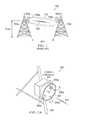
- FIG. 1is an illustration of a conventional point-to-point antenna communications system 100 illustrating the aforementioned misalignment of the antennas.
- FIG. 1depicts two towers 102 a and 102 b with antennas 106 a and 106 b being coupled to the towers using mounts 104 a and 104 b .
- the mounts 104 a and 104 btypically include brackets and other hardware to lock the associated antenna in a fixed position on the respective towers.
- the signal 108 from antenna 106 ais angled slightly downward, away from the receiving antenna 106 b and, therefore, the antenna pattern 110 of the signal 108 is outside of the optimal receiving range of the receiving antenna 108 .
- Alignment problemsmay result from a number of reasons, including, and most often, weather conditions. Even though the brackets 104 a and 104 b are configured to lock the antennas 106 a and 106 b in a fixed position, weather conditions that produce a lot of wind, such as rainstorms and hurricanes, may cause the dish antennas being used for point-to-point network communications to become misaligned such that point-to-point communications degrade. While storms can be a problem, because an antenna may be located high above the ground, a ground wind speed of 20-30 miles per hour may be a wind speed of 80-100 miles per hour at the antenna. While these problems are generally associated with dish antennas being mounted on towers, the same or similar problems may exist from non-dish antennas or antennas positioned on other structures, such as buildings, poles, or the ground.
- One problem that occurs due to the degradation of communicationsis that reliability of a network degrades to the point of an outage occurring. If an outage occurs for more than 6 minutes, a report to a governmental body, such as the Federal Communications Commission, must be made and, in some cases, fines may be imposed on a communications carrier that operates the network or maintains the communications link between the point-to-point antennas. Furthermore, the antenna manufacturer may have to lower reliability reporting of the antenna (e.g., from 0.999 to 0.99), which may cause communications carriers to lower their desire to purchase the antenna.
- pole or tower climbersi.e., technicians who climb communications poles or towers
- pole climbersare limited in supply and the time to have one perform the re-alignment may take hours or days. If a misalignment occurs during a storm with precipitation, pole climbers cannot climb the pole, so the misalignment may not be corrected until the storm passes, which may sometimes take several days.
- the costs due to misalignmentmay further be measured in customer attrition, which, if a misalignment occurs each time the wind blows strongly, can be significant.
- the principles of the present inventionprovide for auto re-alignment or remote re-alignment of antennas.
- the antennabeing able to self re-align or an operator being able to remotely re-align the antenna, the cost and delay of an antenna becoming misaligned may be reduced for a network operator.
- reliability of a network link that uses an antenna that is configured using the principles of the present inventionmay be improved or otherwise remains high.
- One embodimentincludes a system for communicating signals point-to-point.
- the systemmay include a first antenna, a second antenna configured to communicate a communications signal with the first antenna using point-to-point communications, and a position controller coupled to the first antenna and configured to re-align the first antenna with respect to the second antenna in response to determining a misalignment of the antenna.
- Another embodimentmay include a method for communicating signals point-to-point.
- a first antennamay receive a communications signal communicated to the first antenna in a point-to-point manner from a second antenna.
- a determination that the first antenna is misalignedmay be made.
- At least one offset angle for re-aligning the first antennamay be determined.
- the first antennamay be re-aligned based on the offset angle(s) independent of a person having to perform the re-alignment at the first antenna.
- FIG. 1is an illustration of a conventional point-to-point antenna communications system that depicts a misalignment of the antennas
- FIG. 2Ais an illustration of an exemplary antenna system including a position controller for re-aligning an antenna
- FIG. 2Bis an illustration of a frontal view of the antenna of FIG. 2A depicting four antenna elements used for sensing communications signals;
- FIG. 2Cis an illustration of a frontal view of the dish antenna of FIG. 2A depicting an antenna array used for sensing communications signals at a focal plane of the dish antenna;
- FIG. 2Dis an illustration of a side view of the dish antenna of FIG. 2C depicting the antenna array positioned at a focal plane of the dish antenna;
- FIG. 3is an illustration of an exemplary communications system enabling remote re-alignment of an antenna
- FIG. 4is a depiction of an exemplary position controller for use in re-aligning an antenna
- FIG. 5is a depiction of an exemplary remote controller operating within a network operations center
- FIG. 6is a graph depicting overall power of a communications signal received at an antenna
- FIG. 7is a depiction of an exemplary polar chart showing a location of aggregated power of a communications signal being received by an antenna
- FIG. 8is a graph depicting signal strength received from various quadrants of an antenna
- FIG. 9is a timing diagram representing signal flow between various components of a position controller.
- FIG. 10is a flow chart of an exemplary process for re-aligning an antenna.
- an auto-sensing algorithmis incorporated into a position controller that is attached to an antenna to automatically adjust the elevation and azimuth positions of the antenna.
- the principles of the present inventionmay also include a semi-automatic and manual mode for allowing a remote operator to manually adjust the antenna using signal strength or position information returned from a position controller.
- FIG. 2Ais an illustration of an exemplary antenna system 200 including a position controller 202 for re-aligning an antenna.
- the position controller 202may be configured to rotate the antenna 106 in both the elevation and azimuth directions as depicted by rotation arrows 205 a - 205 d .
- the position controller 202 and antenna 204are integrated as a single unit.
- the position controller 202 and antenna 204are separate components that may be coupled together during installation.
- the position controller 202may be mounted to tower 206 . Although shown as a tower 206 , the position controller 202 may be mounted to a variety of structures, including buildings, poles, or otherwise. The position controller 202 remains stationary relative to the tower 206 , while the position controller 202 may adjust position of the antenna 204 in a range of directions. Being able to adjust the position of the antenna 204 in azimuth and elevation angles allows an antenna element 208 used for transmitting and receiving communications signals 210 to be re-aligned for improving communication performance, especially when used in point-to-point communications.
- FIG. 2Bis an illustration of a frontal view of the antenna 204 of FIG. 2A depicting four antenna elements 208 a - 208 d (collectively 208 ) used for receiving communications signals. These antenna elements 208 may also be used for transmitting the communications signals. Alternatively, another antenna element (not shown) positioned in front of a center point of the antenna 204 may be used to transmit the communications signals. As understood in the art, the antenna elements 208 may be positioned to receive the communications signals reflected from quadrants A, B, C, and D of the antenna 204 , respectively. Collecting communications signals reflected from each quadrant of the antenna enables power being received at each quadrant to be separately determined and used for re-aligning the antenna.
- the antenna elements 208 being separate elementsis exemplary. Other configurations are possible, including an antenna array positioned at a focal plane of the dish antenna 204 .
- FIG. 2Cis an illustration of a frontal view of the dish antenna 204 of FIG. 2A depicting an antenna array 212 used for sensing communications signals from the dish antenna 204 .
- the antenna array 212is positioned in a focal plane of the dish antenna 204 .
- the focal planeis the distance at which radio frequency communications signals are focused from the dish antenna 204 to maximize signal power. If the dish antenna 204 is aligned such that it is pointing directly toward another antenna with which communications signals are being communicated, the communications signals will be focused at the center point of the antenna array 212 (i.e., the antenna array is at boresight).
- the communications signals being reflected from the dish antenna 204will be focused off of the center of the antenna array 212 , such as at focal point location 214 .
- the antenna array 212may be configured such that the position controller 202 can determine the position of the focal point location 214 and re-align the dish antenna 204 to cause the focal point location 214 to be re-centered on the antenna array 212 .
- communication signals 210 communicated between antennasmay be composed of any type of communications signal, including WiFi signals.
- signal strength in any given location on the antennacan be more finely detected based on a higher number of inputs.
- the use of four or more antenna elements 208provides for sensing signal strength being received by the antenna 204 to enable determination of antenna orientation or alignment, thereby enabling a determination of re-alignment in the event of the antenna 204 becoming misaligned due to weather conditions, for example.
- FIG. 2Dis an illustration of a side view of the dish antenna 204 of FIG. 2C depicting the antenna array 212 positioned at a focal plane of the dish antenna 204 .
- a communications signal 216is incident on the dish antenna 204 and is reflected onto the antenna array 212 at a focal point 214 .
- the focal point 214 of the reflected communications signal 218is shown to be at an offset distance D from boresight, which can also be represented as azimuth and elevation angles (AZ, EL).
- the position controller 202may use information of the offset distance and re-align the antenna to boresight, thereby minimizing loss of communications signals or information contained in the communications signals.
- FIG. 3is an illustration of an exemplary communications system 300 enabling remote re-alignment of an antenna 204 .
- the principles of the present inventioninclude a network operations center (NOC) 302 operating a remote controller 304 in communication, via a network 306 , with the position controller 200 ( FIG. 2 ).
- NOC 302is located remotely from the tower 206 and uses the remote controller 304 for manually, semi-automatically, or automatically controlling the direction of the antenna 204 .
- the remote controller 304receives signal data provided by the position controller 202 over the network 306 .
- the operatorcan view a display ( FIG. 5 ) showing signal strengths received from each antenna element 208 and manually adjust the direction of the antenna from the remote NOC 302 .
- the remote controller 304may receive signals from the position controller 202 , but the user would not manually control the antenna as the antenna 204 would be controlled using embedded algorithms at the remote controller similar or the same as those in the position controller 202 .
- the systemcan be configured to notify an operator of the antenna 106 when the power level of the communications signal drops below a set threshold (e.g., ⁇ 3 dB below an initial setting).
- a calibrated communications signal having a predetermined power level that causes a certain measured power level at the position controller 202 or remote controller 304 to be measuredmay be communicated periodically, aperiodically, in response to an event, or by an operator to cause re-alignment of the antenna.
- the calibrated communications signalmay include re-calibration triggering information, such as a specific sequence of bits that the position controller 202 or remote controller 304 can identify and execute a re-calibration operation based on the received calibration signal.
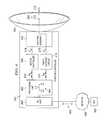
- FIG. 4is a depiction of an exemplary position controller 202 for use in re-aligning an antenna 204 .
- the position controller 202includes a processing unit 402 that executes software 404 .
- the processing unit 402may be in communication with an input/output (I/O) unit 406 , motion controller 408 , and radio receiver circuit 410 .
- the motion controller 408may be in communication with a rotating assembly 412 , which is coupled to antenna 204 for re-aligning the antenna 204 .
- the software 404may be configured to perform automatic feedback processing for re-aligning the antenna 204 .
- the position controller 202may be a stand-alone device, such that the position controller 202 does not communicate or receive position information from a remote device, such as the remote controller 304 , of the antenna 204 , but may communicate information received from communication signals 210 as received by antenna element 208 .
- the software 404may be configured to perform automatic position control for controlling re-alignment operations of the antenna 204 based on the communication signals 210 received by the antenna element 208 .
- the processing unit 402 executing the software 404may perform conventional automatic position control functionality, such as using a proportional-integral-derivative (PID) control algorithm, in both azimuth elevation planes.
- PIDproportional-integral-derivative
- the radio receiver circuit 410receives the communications signals 210 from an antenna element, where the antenna element may be an antenna element 208 ( FIG. 2B ) or antenna array 212 ( FIG. 2C ).
- the radio receiver circuit 410may perform an analog-to-digital (A/D) conversion to convert the communication signals 210 into digital signals 414 .
- A/Danalog-to-digital
- the radio receiver circuit 410may convert the communication signals 210 received from each of the individual antenna elements 208 and the software 404 may distinguish between each of the signals being received by the different antenna elements 208 .
- the software 404may perform difference and summation algorithms to determine signal strengths being received by each antenna element 208 so that a re-alignment determination for the antenna 204 may be made.
- the antenna elements 208 that are positioned in different quadrants of the antennamay be used to perform re-alignment of the antenna 204 depending upon which quadrant is receiving communications signals 210 with the highest power. Performing such determination using software is well understood in the art of object tracking using remote sensors.
- a determination of peak power locationmay be made by the processing unit 402 to determine position of the communications signals focused on the antenna array 212 by the dish antenna 204 .
- the processing unit 402may use the position of the communications signals focused on the antenna array 212 as feedback to re-align the dish antenna 204 .
- the processing unit 402may be configured to receive feedback signals from the rotating assembly 412 and use those signals to re-align the dish antenna 204 .
- the position controller 202in this instance, may be established with an initial boresight alignment and use angular offsets from that initial boresight to re-align the antenna 204 .
- the automatic control algorithms for maintaining alignment of the antenna 204is understood in the art. Such re-alignment may be performed continuously, periodically, or otherwise.
- the processing unit 402may generate command signals 416 based on determining the position of the aggregated or focused communications signals and communicate the command signals 416 to the motion controller 408 .
- the motion controller 408in response to receiving the command signals 416 , may perform a digital-to-analog (D/A) conversion and generate analog command signals 418 for communication to the rotating assembly 412 .
- the rotating assemblymay be configured to receive the analog command signals 418 and perform an electromechanical operation to drive or otherwise reposition the antenna 204 for re-alignment.
- the rotating assembly 412may include motors, gears, and other mechanical drive components in both elevation and azimuth planes for moving the antenna 204 . Such drive mechanisms are understood in the art.
- the motion controller 408may include preamplifiers, amplifiers, and other electronic hardware for generating analog command signals 418 that are used to drive motors or other electromechanical devices in the rotating assembly 412 .
- the I/O unit 406may be in communication with network 308 .
- Data packets 420may be communicated between the I/O unit 406 and network 308 .
- the data packets 420may include information received within the communication signals 210 in the form of digital data. Additionally, the data packets 420 may include position signals indicative of the position of the antenna 204 . In one embodiment, the position signals may include actual or relative position signals to allow an operator located in the NOC 302 to monitor position in operation of the position controller 202 and antenna 204 .
- the operational modesmay include an automatic, semi-automatic, and manual mode.
- the position controller 202can have several different configurations depending upon the mode that the position controller 202 is designed to operate.
- the position controller 202may include software 404 that operates independent of receiving any external inputs from the NOC 302 by receiving the communication signals 210 received by the antenna element 208 and processing those signals to determine a precise direction that the antenna 204 is pointing. It should be understood that because of the precision used to communicate and receive the signals to maintain a signal-to-noise ratio without losing information being communicated in the communication signals 210 .
- an operator at the NOC 302may communicate signals to the position controller 202 via the I/O Unit 406 to cause the processing unit 402 to automatically re-align the antenna 204 .
- An operator at the NOC 302may issue the re-alignment command to the position controller 202 when the communication signals 210 are determined by an operator to be below a threshold value, for example.
- the operatormay issue a re-calibration command to the position controller 202 as a routine procedure to ensure quality communications.
- an operatormay issue a re-calibration command signal to the position controller during or after a weather phenomenon, such as a thunderstorm to ensure that the antenna 204 is properly aligned.
- the position controller 202may operate in a manual mode by having software 404 operate as a slave to position commands communicated from the NOC 302 via the I/O unit 406 .
- the position commandsmay be generated by an operator entering information via a graphical user interface ( FIG. 5 ) or pointing device, such as a computer mouse or joystick.
- the software 404is configured to receive position commands and communicate the commands to the motion controller 408 , which, in response, drives the rotating assembly 412 to move the antenna 204 to the desired position.
- An operatormay receive feedback of the position of the antenna 204 in a number of ways, including signal strength of the communication signals 210 being received by the antenna element 208 , position sensors contained within the rotating assembly 412 , or otherwise as understood in the art.
- the rotating assembly 412may include mechanical, electrical, or optical sensors that monitor absolute or relative positions of the antenna 204 .
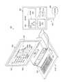
- FIG. 5is a depiction of an exemplary remote controller 500 operating within a network operations center.
- the remote controller 500may include a server 502 or other computing device that is used to receive information via network 308 from a position controller (not shown).
- the server 502may be in communication with an electronic display 504 that may be utilized to display a graphical user interface (GUI) 506 that an operator may use to interface and control position of an antenna via a position controller, for example.
- GUIgraphical user interface
- the server 502may include a processor 508 that executes software 510 .
- the processor 508may be in communication with a memory 512 , I/O unit 514 , and storage unit 516 that may store a database 518 thereon.
- the software 510may be configured to collect information being communicated via data packets 520 representative of position information of an antenna and information communicated in communications signals being received at the antenna.
- the position informationis representative of power received by antenna elements at different quadrants, thereby enabling the software 510 to determine a direction to adjust or re-align an antenna.
- the position informationmay be representative of angular position relative to an initial position of the antenna in both azimuth and elevation directions.
- the information received by the processor 508may be stored in the memory 512 during operation or in the database 518 .
- the position informationmay be displayed on the GUI 506 .
- the GUI 506may include a display portion 522 that includes information associated with one or more antennas.
- the information associated with the antenna(s)may include antenna number, antenna location, antenna azimuth angle, antenna elevation angle, and mode (e.g., automatic) for re-aligning the antenna.
- the GUI 506may include a graphics portion 524 that may display power or signal strength associated with communication signals being received by the antenna. Alternatively or additionally, the graphics portion 524 may display a graphical representation of absolute or relative angle of the antenna as currently positioned.
- a graph showing azimuth and elevation angles relative to boresight as originally positioned and calibratedmay be displayed using Cartesian or other graphical format.
- An operatormay manually adjust position of the antenna by entering new azimuth and elevation values in text entry fields 526 a and 526 b , respectively.
- other graphical user interface elementssuch as up and down arrows, may be utilized for adjusting position of the antenna.
- the operatormay select the mode of operation of the position controller by selecting automatic, semi-automatic, or manual in entry field 528 . If selected to be in automatic mode, the position controller 202 may operate to re-align the antenna independent of commands by the remote controller 500 .
- the operatormay use a keyboard 530 or pointing device 532 , such as a computer mouse, joystick or otherwise.
- the software 510may be configured to re-align antennas in manual, semi-automatic, and automatic modes.
- the software 510may be configured the same or similar to the software in the position controller 202 of FIG. 4 , whereby the software determines the position of the antenna by determining power levels being received by the antenna elements at each quadrant. In making such a determination, a calibration signal may be communicated from a different antenna to the antenna being re-aligned.
- Command signals for re-aligning the antennamay be communicated via the data packets 520 by the processor 508 via the I/O unit 514 over the network 308 to the position controller associated with the antenna being re-aligned.
- FIG. 6is a graph 600 depicting overall power or signal strength of an exemplary communications signal received at an antenna.
- the graph 600has three axes, including signal strength on the left vertical axis 602 , frequency on the bottom horizontal axis 604 , and antenna alignment angle on the right vertical axis 606 .
- Three signal power curves 608 , 610 , and 612are shown on the graph 600 .
- Each of these curves 608 , 610 , and 612represents an antenna being at different angles with respect to another antenna to which the antenna is communicating.
- Signal curve 608is at 0 degrees (boresight) and has a signal strength of ⁇ 10 dBm
- Signal curve 610is at a 1 degree offset angle from boresight and has ⁇ 13 dBm signal strength.
- a difference of ⁇ 3 dBmis a loss of half of the power from the antenna being at boresight, which means that errors in a communications signal may occur due to the misalignment of 1 degree of the antenna.
- the signal curve 612is reflective of the antenna being at a 2 degree offset angle from boresight and has a ⁇ 16 dBm power level.
- the ⁇ 16 dBm power levelis 6 dBm below the power level of the antenna from boresight, which is a significant drop below the maximum power level and interruptions of communication may undoubtedly result. Such significant drops for such small angular deviations are a result of the antennas being configured to have point-to-point communications and using a narrow beam for communications.
- FIG. 7is a depiction of an exemplary polar chart showing location of aggregated power of a communication signal being received by an antenna.
- the polar chart 700is configured to have four quadrants, A, B, C, and D. Each of these quadrants are representative of the quadrants of an antenna (see, for example, FIG. 2B ).
- a communications signal received by antenna elements, such as antenna elements 208 of FIG. 2Bmay be aggregated to determine position of the antenna so as to determine how to re-align the antenna to cause the antenna to be returned to boresight.
- a processor receiving the communications signal from each of the antenna elementsdetermine that the aggregated communications signal is positioned at a point 702 that is 2 degrees offset from boresight.
- the position controller or remote controllermay determine that the antenna needs to be re-aligned by driving the antenna in both the azimuth in elevation directions in quadrant D so as to move the aggregated communications to boresight.
- FIG. 8is a graph depicting signal strength from various quadrants of an antenna. Five signal curves are shown, including a total signal curve T and signal curves from each of four antenna elements located in respective quadrants A, B, C, and D. As shown, signal curve B has the highest power level, signal curve A has the second highest power level, signal curve D has the third highest signal level, and signal curve C has the lowest signal power. Aggregating the signal levels of each of the antenna elements results in the signal curve T, which is at ⁇ 13 dBm. Because the signal levels are spread, the position controller or remote controller can determine that the antenna is not at boresight. In addition, an operator may view the graph 800 and also determine that the antenna is not at boresight. Once the antenna is re-aligned, the individual signal curves A, B, C and D, should substantially overlap with one another and the total signal power curve should increase from ⁇ 13 dBm to ⁇ 10 dBm.
- FIG. 9is a timing diagram representing an exemplary signal flow between various components of a position controller 202 .
- the components of the position controller 202include a processing unit 402 , radio receiver circuit 410 , motion controller 408 , and rotating assembly 412 . It should be understood that these components may be combined or further separated but operate in the same or similar manner as described herein in accordance with the principles of the present invention.
- the radio receiver circuit 410receives communication signals and generates power levels at step 902 .
- the power levels generatedmay be associated with four or more antenna elements that are configured in association with quadrants with an antenna.
- the power levelsare communicated from the radio receiver circuit 410 to the process unit 402 .
- the processing unit 402determines one or more angles to re-align the antenna.
- the anglesmay be both azimuth and elevation angles. It should be understood that if another coordinate system other than a Cartesian coordinate system is used, then other parameters may be generated. For example, the processing unit 402 may determine distance and angle (r, ⁇ ) if a polar coordinate system is being used.
- the processing unit 402may communicate the offset angles to re-align the antenna to the motion controller 408 .
- the motion controllermay generate control signals that are used to drive the rotating assembly 412 .
- the control signalsmay be communicated to the rotating assembly 412 and the rotating assembly, in response, performs a re-align positioning of the antenna in both azimuth and elevation planes.
- the motion controller 408may communicate and indicated to the processing unit 402 that the re-alignment is complete at step 916 .
- the processing unitmay repeat the process of re-aligning the position of the antenna. The re-alignment process may be performed continuously, periodically, in response to an event, in response to a manual notification by an operator, or at any other interval.
- the processing unit 402may be configured to wait for the power levels 904 to drop below a threshold level, optionally established by an operator using a GUI, in the aggregate or at each antenna element before performing a re-alignment operation.
- a threshold leveloptionally established by an operator using a GUI
- the antennamay be re-aligned in response to becoming out of alignment by a predetermined angle (e.g., 1 degree).
- an operator of the antennamay have costs substantially reduced due to not having a technician having to climb a tower to perform the antenna re-alignment.
- quality of the antenna and communications systemmay be improved by not having communications problems caused degradation of communication signals for point-to-point communications.
- dish antennasother types of antennas having narrow beam widths for point-to-point communications that can utilize the principles of the present invention may be utilized.
- FIG. 10is a flow chart of an exemplary process 1000 for re-aligning an antenna.
- the process 1000starts at step 1002 .
- a communications signal communicated in a point-to-point manneri.e., a dedicated communications link from one antenna to another antenna
- a determinationis made that the antenna is misaligned.
- the determinationmay be made using one of a number of different techniques, including determining that power of the communications signal has dropped below a threshold value, determining that an aggregated power location of the communications signal (i.e., the effective center of power) has moved from a boresight location to an off-boresight location on the antenna, determining that the antenna has physically moved based on electromechanical (e.g., motor, gear, potentiometer, etc.) or optical components (optical encoder) sensing an offset from an initial or calibrated boresight position.
- electromechanicale.g., motor, gear, potentiometer, etc.
- optical componentsoptical encoder
- the determinationmay be made at the antenna (e.g., by a position controller at the antenna location), remotely (e.g., by a remote controller over a network or manually by an operator at the remote controller).
- the antennamay be re-aligned based on the offset angle(s) independent of a person having to perform the re-alignment at the antenna at step 1010 .
- the antennamay be re-aligned using electromechanical components without a technician or other person having to climb a tower or otherwise physically access the antenna to move the antenna into a re-aligned position.
- the re-aligningmay use automatic control feedback algorithms (e.g., PID controller), non-feedback control methods (e.g., slave commands to a stepper motor), or manually (e.g., graph or other image on a GUI at a remote controller).
- PID controllere.g., PID controller
- non-feedback control methodse.g., slave commands to a stepper motor
- manuallye.g., graph or other image on a GUI at a remote controller
Landscapes
- Variable-Direction Aerials And Aerial Arrays (AREA)
Abstract
Description
Claims (22)
Priority Applications (1)
| Application Number | Priority Date | Filing Date | Title |
|---|---|---|---|
| US11/888,832US8022885B2 (en) | 2007-08-02 | 2007-08-02 | System and method for re-aligning antennas |
Applications Claiming Priority (1)
| Application Number | Priority Date | Filing Date | Title |
|---|---|---|---|
| US11/888,832US8022885B2 (en) | 2007-08-02 | 2007-08-02 | System and method for re-aligning antennas |
Publications (2)
| Publication Number | Publication Date |
|---|---|
| US20090033576A1 US20090033576A1 (en) | 2009-02-05 |
| US8022885B2true US8022885B2 (en) | 2011-09-20 |
Family
ID=40337624
Family Applications (1)
| Application Number | Title | Priority Date | Filing Date |
|---|---|---|---|
| US11/888,832Active2028-07-30US8022885B2 (en) | 2007-08-02 | 2007-08-02 | System and method for re-aligning antennas |
Country Status (1)
| Country | Link |
|---|---|
| US (1) | US8022885B2 (en) |
Cited By (173)
| Publication number | Priority date | Publication date | Assignee | Title |
|---|---|---|---|---|
| US20120143561A1 (en)* | 2010-12-03 | 2012-06-07 | Stisser Daryl A | Alignment detection device |
| US20120319895A1 (en)* | 2009-12-13 | 2012-12-20 | Tomer Bruchiel | System and method for accurately directing antennas |
| US20140057570A1 (en)* | 2012-08-23 | 2014-02-27 | Siklu Communication ltd. | Systems and methods for optimizing communication performance |
| US9312919B1 (en) | 2014-10-21 | 2016-04-12 | At&T Intellectual Property I, Lp | Transmission device with impairment compensation and methods for use therewith |
| US9461706B1 (en) | 2015-07-31 | 2016-10-04 | At&T Intellectual Property I, Lp | Method and apparatus for exchanging communication signals |
| US9467870B2 (en) | 2013-11-06 | 2016-10-11 | At&T Intellectual Property I, L.P. | Surface-wave communications and methods thereof |
| US9479266B2 (en) | 2013-12-10 | 2016-10-25 | At&T Intellectual Property I, L.P. | Quasi-optical coupler |
| US9490869B1 (en) | 2015-05-14 | 2016-11-08 | At&T Intellectual Property I, L.P. | Transmission medium having multiple cores and methods for use therewith |
| US9503189B2 (en) | 2014-10-10 | 2016-11-22 | At&T Intellectual Property I, L.P. | Method and apparatus for arranging communication sessions in a communication system |
| US9509415B1 (en) | 2015-06-25 | 2016-11-29 | At&T Intellectual Property I, L.P. | Methods and apparatus for inducing a fundamental wave mode on a transmission medium |
| US9520945B2 (en) | 2014-10-21 | 2016-12-13 | At&T Intellectual Property I, L.P. | Apparatus for providing communication services and methods thereof |
| US9525210B2 (en) | 2014-10-21 | 2016-12-20 | At&T Intellectual Property I, L.P. | Guided-wave transmission device with non-fundamental mode propagation and methods for use therewith |
| US9525524B2 (en) | 2013-05-31 | 2016-12-20 | At&T Intellectual Property I, L.P. | Remote distributed antenna system |
| US9531427B2 (en) | 2014-11-20 | 2016-12-27 | At&T Intellectual Property I, L.P. | Transmission device with mode division multiplexing and methods for use therewith |
| US9564947B2 (en) | 2014-10-21 | 2017-02-07 | At&T Intellectual Property I, L.P. | Guided-wave transmission device with diversity and methods for use therewith |
| US9577307B2 (en) | 2014-10-21 | 2017-02-21 | At&T Intellectual Property I, L.P. | Guided-wave transmission device and methods for use therewith |
| US9608740B2 (en) | 2015-07-15 | 2017-03-28 | At&T Intellectual Property I, L.P. | Method and apparatus for launching a wave mode that mitigates interference |
| US9608692B2 (en) | 2015-06-11 | 2017-03-28 | At&T Intellectual Property I, L.P. | Repeater and methods for use therewith |
| US9615269B2 (en) | 2014-10-02 | 2017-04-04 | At&T Intellectual Property I, L.P. | Method and apparatus that provides fault tolerance in a communication network |
| US9628854B2 (en) | 2014-09-29 | 2017-04-18 | At&T Intellectual Property I, L.P. | Method and apparatus for distributing content in a communication network |
| US9628116B2 (en) | 2015-07-14 | 2017-04-18 | At&T Intellectual Property I, L.P. | Apparatus and methods for transmitting wireless signals |
| US9640850B2 (en) | 2015-06-25 | 2017-05-02 | At&T Intellectual Property I, L.P. | Methods and apparatus for inducing a non-fundamental wave mode on a transmission medium |
| US9653770B2 (en) | 2014-10-21 | 2017-05-16 | At&T Intellectual Property I, L.P. | Guided wave coupler, coupling module and methods for use therewith |
| US9654173B2 (en) | 2014-11-20 | 2017-05-16 | At&T Intellectual Property I, L.P. | Apparatus for powering a communication device and methods thereof |
| US9667317B2 (en) | 2015-06-15 | 2017-05-30 | At&T Intellectual Property I, L.P. | Method and apparatus for providing security using network traffic adjustments |
| US9680670B2 (en) | 2014-11-20 | 2017-06-13 | At&T Intellectual Property I, L.P. | Transmission device with channel equalization and control and methods for use therewith |
| US9685992B2 (en) | 2014-10-03 | 2017-06-20 | At&T Intellectual Property I, L.P. | Circuit panel network and methods thereof |
| US9692101B2 (en) | 2014-08-26 | 2017-06-27 | At&T Intellectual Property I, L.P. | Guided wave couplers for coupling electromagnetic waves between a waveguide surface and a surface of a wire |
| US9699785B2 (en) | 2012-12-05 | 2017-07-04 | At&T Intellectual Property I, L.P. | Backhaul link for distributed antenna system |
| US9705571B2 (en) | 2015-09-16 | 2017-07-11 | At&T Intellectual Property I, L.P. | Method and apparatus for use with a radio distributed antenna system |
| US9705561B2 (en) | 2015-04-24 | 2017-07-11 | At&T Intellectual Property I, L.P. | Directional coupling device and methods for use therewith |
| US9722318B2 (en) | 2015-07-14 | 2017-08-01 | At&T Intellectual Property I, L.P. | Method and apparatus for coupling an antenna to a device |
| US9729197B2 (en) | 2015-10-01 | 2017-08-08 | At&T Intellectual Property I, L.P. | Method and apparatus for communicating network management traffic over a network |
| US9735833B2 (en) | 2015-07-31 | 2017-08-15 | At&T Intellectual Property I, L.P. | Method and apparatus for communications management in a neighborhood network |
| US9742462B2 (en) | 2014-12-04 | 2017-08-22 | At&T Intellectual Property I, L.P. | Transmission medium and communication interfaces and methods for use therewith |
| US9748626B2 (en) | 2015-05-14 | 2017-08-29 | At&T Intellectual Property I, L.P. | Plurality of cables having different cross-sectional shapes which are bundled together to form a transmission medium |
| US9749053B2 (en) | 2015-07-23 | 2017-08-29 | At&T Intellectual Property I, L.P. | Node device, repeater and methods for use therewith |
| US9749013B2 (en) | 2015-03-17 | 2017-08-29 | At&T Intellectual Property I, L.P. | Method and apparatus for reducing attenuation of electromagnetic waves guided by a transmission medium |
| US9755697B2 (en) | 2014-09-15 | 2017-09-05 | At&T Intellectual Property I, L.P. | Method and apparatus for sensing a condition in a transmission medium of electromagnetic waves |
| US9762289B2 (en) | 2014-10-14 | 2017-09-12 | At&T Intellectual Property I, L.P. | Method and apparatus for transmitting or receiving signals in a transportation system |
| US9769128B2 (en) | 2015-09-28 | 2017-09-19 | At&T Intellectual Property I, L.P. | Method and apparatus for encryption of communications over a network |
| US9769020B2 (en) | 2014-10-21 | 2017-09-19 | At&T Intellectual Property I, L.P. | Method and apparatus for responding to events affecting communications in a communication network |
| US9780834B2 (en) | 2014-10-21 | 2017-10-03 | At&T Intellectual Property I, L.P. | Method and apparatus for transmitting electromagnetic waves |
| US9793955B2 (en) | 2015-04-24 | 2017-10-17 | At&T Intellectual Property I, Lp | Passive electrical coupling device and methods for use therewith |
| US9793954B2 (en) | 2015-04-28 | 2017-10-17 | At&T Intellectual Property I, L.P. | Magnetic coupling device and methods for use therewith |
| US9793951B2 (en) | 2015-07-15 | 2017-10-17 | At&T Intellectual Property I, L.P. | Method and apparatus for launching a wave mode that mitigates interference |
| US9800327B2 (en) | 2014-11-20 | 2017-10-24 | At&T Intellectual Property I, L.P. | Apparatus for controlling operations of a communication device and methods thereof |
| US9820146B2 (en) | 2015-06-12 | 2017-11-14 | At&T Intellectual Property I, L.P. | Method and apparatus for authentication and identity management of communicating devices |
| US9836957B2 (en) | 2015-07-14 | 2017-12-05 | At&T Intellectual Property I, L.P. | Method and apparatus for communicating with premises equipment |
| US9838896B1 (en) | 2016-12-09 | 2017-12-05 | At&T Intellectual Property I, L.P. | Method and apparatus for assessing network coverage |
| US9847566B2 (en) | 2015-07-14 | 2017-12-19 | At&T Intellectual Property I, L.P. | Method and apparatus for adjusting a field of a signal to mitigate interference |
| US9847850B2 (en) | 2014-10-14 | 2017-12-19 | At&T Intellectual Property I, L.P. | Method and apparatus for adjusting a mode of communication in a communication network |
| US9853342B2 (en) | 2015-07-14 | 2017-12-26 | At&T Intellectual Property I, L.P. | Dielectric transmission medium connector and methods for use therewith |
| US9860075B1 (en) | 2016-08-26 | 2018-01-02 | At&T Intellectual Property I, L.P. | Method and communication node for broadband distribution |
| US9866309B2 (en) | 2015-06-03 | 2018-01-09 | At&T Intellectual Property I, Lp | Host node device and methods for use therewith |
| US9865911B2 (en) | 2015-06-25 | 2018-01-09 | At&T Intellectual Property I, L.P. | Waveguide system for slot radiating first electromagnetic waves that are combined into a non-fundamental wave mode second electromagnetic wave on a transmission medium |
| US9871283B2 (en) | 2015-07-23 | 2018-01-16 | At&T Intellectual Property I, Lp | Transmission medium having a dielectric core comprised of plural members connected by a ball and socket configuration |
| US9871282B2 (en) | 2015-05-14 | 2018-01-16 | At&T Intellectual Property I, L.P. | At least one transmission medium having a dielectric surface that is covered at least in part by a second dielectric |
| US9876264B2 (en) | 2015-10-02 | 2018-01-23 | At&T Intellectual Property I, Lp | Communication system, guided wave switch and methods for use therewith |
| US9876570B2 (en) | 2015-02-20 | 2018-01-23 | At&T Intellectual Property I, Lp | Guided-wave transmission device with non-fundamental mode propagation and methods for use therewith |
| US9876605B1 (en) | 2016-10-21 | 2018-01-23 | At&T Intellectual Property I, L.P. | Launcher and coupling system to support desired guided wave mode |
| US9882277B2 (en) | 2015-10-02 | 2018-01-30 | At&T Intellectual Property I, Lp | Communication device and antenna assembly with actuated gimbal mount |
| US9882257B2 (en) | 2015-07-14 | 2018-01-30 | At&T Intellectual Property I, L.P. | Method and apparatus for launching a wave mode that mitigates interference |
| US9893795B1 (en) | 2016-12-07 | 2018-02-13 | At&T Intellectual Property I, Lp | Method and repeater for broadband distribution |
| US9906269B2 (en) | 2014-09-17 | 2018-02-27 | At&T Intellectual Property I, L.P. | Monitoring and mitigating conditions in a communication network |
| US9904535B2 (en) | 2015-09-14 | 2018-02-27 | At&T Intellectual Property I, L.P. | Method and apparatus for distributing software |
| US9912027B2 (en) | 2015-07-23 | 2018-03-06 | At&T Intellectual Property I, L.P. | Method and apparatus for exchanging communication signals |
| US9912382B2 (en) | 2015-06-03 | 2018-03-06 | At&T Intellectual Property I, Lp | Network termination and methods for use therewith |
| US9911020B1 (en) | 2016-12-08 | 2018-03-06 | At&T Intellectual Property I, L.P. | Method and apparatus for tracking via a radio frequency identification device |
| US9913139B2 (en) | 2015-06-09 | 2018-03-06 | At&T Intellectual Property I, L.P. | Signal fingerprinting for authentication of communicating devices |
| US9912419B1 (en) | 2016-08-24 | 2018-03-06 | At&T Intellectual Property I, L.P. | Method and apparatus for managing a fault in a distributed antenna system |
| US9917341B2 (en) | 2015-05-27 | 2018-03-13 | At&T Intellectual Property I, L.P. | Apparatus and method for launching electromagnetic waves and for modifying radial dimensions of the propagating electromagnetic waves |
| US9927517B1 (en) | 2016-12-06 | 2018-03-27 | At&T Intellectual Property I, L.P. | Apparatus and methods for sensing rainfall |
| US9948354B2 (en) | 2015-04-28 | 2018-04-17 | At&T Intellectual Property I, L.P. | Magnetic coupling device with reflective plate and methods for use therewith |
| US9948333B2 (en) | 2015-07-23 | 2018-04-17 | At&T Intellectual Property I, L.P. | Method and apparatus for wireless communications to mitigate interference |
| US9954287B2 (en) | 2014-11-20 | 2018-04-24 | At&T Intellectual Property I, L.P. | Apparatus for converting wireless signals and electromagnetic waves and methods thereof |
| US9967173B2 (en) | 2015-07-31 | 2018-05-08 | At&T Intellectual Property I, L.P. | Method and apparatus for authentication and identity management of communicating devices |
| US9973940B1 (en) | 2017-02-27 | 2018-05-15 | At&T Intellectual Property I, L.P. | Apparatus and methods for dynamic impedance matching of a guided wave launcher |
| US9991580B2 (en) | 2016-10-21 | 2018-06-05 | At&T Intellectual Property I, L.P. | Launcher and coupling system for guided wave mode cancellation |
| US9999038B2 (en) | 2013-05-31 | 2018-06-12 | At&T Intellectual Property I, L.P. | Remote distributed antenna system |
| US9998870B1 (en) | 2016-12-08 | 2018-06-12 | At&T Intellectual Property I, L.P. | Method and apparatus for proximity sensing |
| US9997819B2 (en) | 2015-06-09 | 2018-06-12 | At&T Intellectual Property I, L.P. | Transmission medium and method for facilitating propagation of electromagnetic waves via a core |
| US10009063B2 (en) | 2015-09-16 | 2018-06-26 | At&T Intellectual Property I, L.P. | Method and apparatus for use with a radio distributed antenna system having an out-of-band reference signal |
| US10009067B2 (en) | 2014-12-04 | 2018-06-26 | At&T Intellectual Property I, L.P. | Method and apparatus for configuring a communication interface |
| US10009901B2 (en) | 2015-09-16 | 2018-06-26 | At&T Intellectual Property I, L.P. | Method, apparatus, and computer-readable storage medium for managing utilization of wireless resources between base stations |
| US10009065B2 (en) | 2012-12-05 | 2018-06-26 | At&T Intellectual Property I, L.P. | Backhaul link for distributed antenna system |
| US10020844B2 (en) | 2016-12-06 | 2018-07-10 | T&T Intellectual Property I, L.P. | Method and apparatus for broadcast communication via guided waves |
| US10020587B2 (en) | 2015-07-31 | 2018-07-10 | At&T Intellectual Property I, L.P. | Radial antenna and methods for use therewith |
| US10027397B2 (en) | 2016-12-07 | 2018-07-17 | At&T Intellectual Property I, L.P. | Distributed antenna system and methods for use therewith |
| US10033108B2 (en) | 2015-07-14 | 2018-07-24 | At&T Intellectual Property I, L.P. | Apparatus and methods for generating an electromagnetic wave having a wave mode that mitigates interference |
| US10033107B2 (en) | 2015-07-14 | 2018-07-24 | At&T Intellectual Property I, L.P. | Method and apparatus for coupling an antenna to a device |
| US10044409B2 (en) | 2015-07-14 | 2018-08-07 | At&T Intellectual Property I, L.P. | Transmission medium and methods for use therewith |
| US10051483B2 (en) | 2015-10-16 | 2018-08-14 | At&T Intellectual Property I, L.P. | Method and apparatus for directing wireless signals |
| US10051629B2 (en) | 2015-09-16 | 2018-08-14 | At&T Intellectual Property I, L.P. | Method and apparatus for use with a radio distributed antenna system having an in-band reference signal |
| US10069535B2 (en) | 2016-12-08 | 2018-09-04 | At&T Intellectual Property I, L.P. | Apparatus and methods for launching electromagnetic waves having a certain electric field structure |
| US10074890B2 (en) | 2015-10-02 | 2018-09-11 | At&T Intellectual Property I, L.P. | Communication device and antenna with integrated light assembly |
| US10079661B2 (en) | 2015-09-16 | 2018-09-18 | At&T Intellectual Property I, L.P. | Method and apparatus for use with a radio distributed antenna system having a clock reference |
| US10090606B2 (en) | 2015-07-15 | 2018-10-02 | At&T Intellectual Property I, L.P. | Antenna system with dielectric array and methods for use therewith |
| US10090594B2 (en) | 2016-11-23 | 2018-10-02 | At&T Intellectual Property I, L.P. | Antenna system having structural configurations for assembly |
| US10103801B2 (en) | 2015-06-03 | 2018-10-16 | At&T Intellectual Property I, L.P. | Host node device and methods for use therewith |
| US10103422B2 (en) | 2016-12-08 | 2018-10-16 | At&T Intellectual Property I, L.P. | Method and apparatus for mounting network devices |
| US10135145B2 (en) | 2016-12-06 | 2018-11-20 | At&T Intellectual Property I, L.P. | Apparatus and methods for generating an electromagnetic wave along a transmission medium |
| US10135146B2 (en) | 2016-10-18 | 2018-11-20 | At&T Intellectual Property I, L.P. | Apparatus and methods for launching guided waves via circuits |
| US10135147B2 (en) | 2016-10-18 | 2018-11-20 | At&T Intellectual Property I, L.P. | Apparatus and methods for launching guided waves via an antenna |
| US10136434B2 (en) | 2015-09-16 | 2018-11-20 | At&T Intellectual Property I, L.P. | Method and apparatus for use with a radio distributed antenna system having an ultra-wideband control channel |
| US10142086B2 (en) | 2015-06-11 | 2018-11-27 | At&T Intellectual Property I, L.P. | Repeater and methods for use therewith |
| US10139820B2 (en) | 2016-12-07 | 2018-11-27 | At&T Intellectual Property I, L.P. | Method and apparatus for deploying equipment of a communication system |
| US10148016B2 (en) | 2015-07-14 | 2018-12-04 | At&T Intellectual Property I, L.P. | Apparatus and methods for communicating utilizing an antenna array |
| US10144036B2 (en) | 2015-01-30 | 2018-12-04 | At&T Intellectual Property I, L.P. | Method and apparatus for mitigating interference affecting a propagation of electromagnetic waves guided by a transmission medium |
| US10154493B2 (en) | 2015-06-03 | 2018-12-11 | At&T Intellectual Property I, L.P. | Network termination and methods for use therewith |
| US10168695B2 (en) | 2016-12-07 | 2019-01-01 | At&T Intellectual Property I, L.P. | Method and apparatus for controlling an unmanned aircraft |
| US10170840B2 (en) | 2015-07-14 | 2019-01-01 | At&T Intellectual Property I, L.P. | Apparatus and methods for sending or receiving electromagnetic signals |
| US10178445B2 (en) | 2016-11-23 | 2019-01-08 | At&T Intellectual Property I, L.P. | Methods, devices, and systems for load balancing between a plurality of waveguides |
| US10205655B2 (en) | 2015-07-14 | 2019-02-12 | At&T Intellectual Property I, L.P. | Apparatus and methods for communicating utilizing an antenna array and multiple communication paths |
| US10224634B2 (en) | 2016-11-03 | 2019-03-05 | At&T Intellectual Property I, L.P. | Methods and apparatus for adjusting an operational characteristic of an antenna |
| US10225025B2 (en) | 2016-11-03 | 2019-03-05 | At&T Intellectual Property I, L.P. | Method and apparatus for detecting a fault in a communication system |
| US10243270B2 (en) | 2016-12-07 | 2019-03-26 | At&T Intellectual Property I, L.P. | Beam adaptive multi-feed dielectric antenna system and methods for use therewith |
| US10243784B2 (en) | 2014-11-20 | 2019-03-26 | At&T Intellectual Property I, L.P. | System for generating topology information and methods thereof |
| US10264586B2 (en) | 2016-12-09 | 2019-04-16 | At&T Mobility Ii Llc | Cloud-based packet controller and methods for use therewith |
| WO2019083552A1 (en)* | 2017-10-27 | 2019-05-02 | Facebook, Inc. | Apparatus, system, and method for pointing wireless communication antennas |
| US10291334B2 (en) | 2016-11-03 | 2019-05-14 | At&T Intellectual Property I, L.P. | System for detecting a fault in a communication system |
| US10291311B2 (en) | 2016-09-09 | 2019-05-14 | At&T Intellectual Property I, L.P. | Method and apparatus for mitigating a fault in a distributed antenna system |
| US10298293B2 (en) | 2017-03-13 | 2019-05-21 | At&T Intellectual Property I, L.P. | Apparatus of communication utilizing wireless network devices |
| US10305190B2 (en) | 2016-12-01 | 2019-05-28 | At&T Intellectual Property I, L.P. | Reflecting dielectric antenna system and methods for use therewith |
| US10312567B2 (en) | 2016-10-26 | 2019-06-04 | At&T Intellectual Property I, L.P. | Launcher with planar strip antenna and methods for use therewith |
| US10320586B2 (en) | 2015-07-14 | 2019-06-11 | At&T Intellectual Property I, L.P. | Apparatus and methods for generating non-interfering electromagnetic waves on an insulated transmission medium |
| US10326494B2 (en) | 2016-12-06 | 2019-06-18 | At&T Intellectual Property I, L.P. | Apparatus for measurement de-embedding and methods for use therewith |
| US10326689B2 (en) | 2016-12-08 | 2019-06-18 | At&T Intellectual Property I, L.P. | Method and system for providing alternative communication paths |
| US10340983B2 (en) | 2016-12-09 | 2019-07-02 | At&T Intellectual Property I, L.P. | Method and apparatus for surveying remote sites via guided wave communications |
| US10340601B2 (en) | 2016-11-23 | 2019-07-02 | At&T Intellectual Property I, L.P. | Multi-antenna system and methods for use therewith |
| US10340603B2 (en) | 2016-11-23 | 2019-07-02 | At&T Intellectual Property I, L.P. | Antenna system having shielded structural configurations for assembly |
| US10341142B2 (en) | 2015-07-14 | 2019-07-02 | At&T Intellectual Property I, L.P. | Apparatus and methods for generating non-interfering electromagnetic waves on an uninsulated conductor |
| US10340600B2 (en) | 2016-10-18 | 2019-07-02 | At&T Intellectual Property I, L.P. | Apparatus and methods for launching guided waves via plural waveguide systems |
| US10340573B2 (en) | 2016-10-26 | 2019-07-02 | At&T Intellectual Property I, L.P. | Launcher with cylindrical coupling device and methods for use therewith |
| US10348391B2 (en) | 2015-06-03 | 2019-07-09 | At&T Intellectual Property I, L.P. | Client node device with frequency conversion and methods for use therewith |
| US10355367B2 (en) | 2015-10-16 | 2019-07-16 | At&T Intellectual Property I, L.P. | Antenna structure for exchanging wireless signals |
| US10359749B2 (en) | 2016-12-07 | 2019-07-23 | At&T Intellectual Property I, L.P. | Method and apparatus for utilities management via guided wave communication |
| US10361489B2 (en) | 2016-12-01 | 2019-07-23 | At&T Intellectual Property I, L.P. | Dielectric dish antenna system and methods for use therewith |
| US10374316B2 (en) | 2016-10-21 | 2019-08-06 | At&T Intellectual Property I, L.P. | System and dielectric antenna with non-uniform dielectric |
| US10382976B2 (en) | 2016-12-06 | 2019-08-13 | At&T Intellectual Property I, L.P. | Method and apparatus for managing wireless communications based on communication paths and network device positions |
| US10389037B2 (en) | 2016-12-08 | 2019-08-20 | At&T Intellectual Property I, L.P. | Apparatus and methods for selecting sections of an antenna array and use therewith |
| US10389029B2 (en) | 2016-12-07 | 2019-08-20 | At&T Intellectual Property I, L.P. | Multi-feed dielectric antenna system with core selection and methods for use therewith |
| US10396887B2 (en) | 2015-06-03 | 2019-08-27 | At&T Intellectual Property I, L.P. | Client node device and methods for use therewith |
| US10411356B2 (en) | 2016-12-08 | 2019-09-10 | At&T Intellectual Property I, L.P. | Apparatus and methods for selectively targeting communication devices with an antenna array |
| US10439675B2 (en) | 2016-12-06 | 2019-10-08 | At&T Intellectual Property I, L.P. | Method and apparatus for repeating guided wave communication signals |
| US10446936B2 (en) | 2016-12-07 | 2019-10-15 | At&T Intellectual Property I, L.P. | Multi-feed dielectric antenna system and methods for use therewith |
| US10498044B2 (en) | 2016-11-03 | 2019-12-03 | At&T Intellectual Property I, L.P. | Apparatus for configuring a surface of an antenna |
| US10530505B2 (en) | 2016-12-08 | 2020-01-07 | At&T Intellectual Property I, L.P. | Apparatus and methods for launching electromagnetic waves along a transmission medium |
| US10535928B2 (en) | 2016-11-23 | 2020-01-14 | At&T Intellectual Property I, L.P. | Antenna system and methods for use therewith |
| US10547348B2 (en) | 2016-12-07 | 2020-01-28 | At&T Intellectual Property I, L.P. | Method and apparatus for switching transmission mediums in a communication system |
| US10601494B2 (en) | 2016-12-08 | 2020-03-24 | At&T Intellectual Property I, L.P. | Dual-band communication device and method for use therewith |
| US10637149B2 (en) | 2016-12-06 | 2020-04-28 | At&T Intellectual Property I, L.P. | Injection molded dielectric antenna and methods for use therewith |
| US10651533B2 (en) | 2016-08-23 | 2020-05-12 | General Electric Company | Sensed situation millimeter-wave communications beam control |
| US10650940B2 (en) | 2015-05-15 | 2020-05-12 | At&T Intellectual Property I, L.P. | Transmission medium having a conductive material and methods for use therewith |
| US10665942B2 (en) | 2015-10-16 | 2020-05-26 | At&T Intellectual Property I, L.P. | Method and apparatus for adjusting wireless communications |
| US10679767B2 (en) | 2015-05-15 | 2020-06-09 | At&T Intellectual Property I, L.P. | Transmission medium having a conductive material and methods for use therewith |
| US10694379B2 (en) | 2016-12-06 | 2020-06-23 | At&T Intellectual Property I, L.P. | Waveguide system with device-based authentication and methods for use therewith |
| US10727599B2 (en) | 2016-12-06 | 2020-07-28 | At&T Intellectual Property I, L.P. | Launcher with slot antenna and methods for use therewith |
| US10755542B2 (en) | 2016-12-06 | 2020-08-25 | At&T Intellectual Property I, L.P. | Method and apparatus for surveillance via guided wave communication |
| US10777873B2 (en) | 2016-12-08 | 2020-09-15 | At&T Intellectual Property I, L.P. | Method and apparatus for mounting network devices |
| US10784670B2 (en) | 2015-07-23 | 2020-09-22 | At&T Intellectual Property I, L.P. | Antenna support for aligning an antenna |
| US10811767B2 (en) | 2016-10-21 | 2020-10-20 | At&T Intellectual Property I, L.P. | System and dielectric antenna with convex dielectric radome |
| US10819035B2 (en) | 2016-12-06 | 2020-10-27 | At&T Intellectual Property I, L.P. | Launcher with helical antenna and methods for use therewith |
| US10916969B2 (en) | 2016-12-08 | 2021-02-09 | At&T Intellectual Property I, L.P. | Method and apparatus for providing power using an inductive coupling |
| US10938108B2 (en) | 2016-12-08 | 2021-03-02 | At&T Intellectual Property I, L.P. | Frequency selective multi-feed dielectric antenna system and methods for use therewith |
| US20210116490A1 (en)* | 2017-03-17 | 2021-04-22 | Nec Corporation | Antenna direction adjustment apparatus, antenna direction adjustment system, and method therefor |
| US11032819B2 (en) | 2016-09-15 | 2021-06-08 | At&T Intellectual Property I, L.P. | Method and apparatus for use with a radio distributed antenna system having a control channel reference signal |
| US11096068B1 (en) | 2015-10-22 | 2021-08-17 | Atavious F. Burt | Panel antenna monitoring |
| WO2022063439A1 (en)* | 2020-09-25 | 2022-03-31 | Telefonaktiebolaget Lm Ericsson (Publ) | Reflector antenna assembly |
| US11442177B2 (en) | 2019-06-20 | 2022-09-13 | Intelibs, Inc. | System and method to transport GPS signals and radio frequency signals over a fiber optic channel with power supplied over the fiber optic channel |
| US11463366B1 (en)* | 2020-09-22 | 2022-10-04 | Architecture Technology Corporation | Autonomous network optimization using network templates |
| WO2023146450A1 (en)* | 2022-01-31 | 2023-08-03 | Telefonaktiebolaget Lm Ericsson (Publ) | Compensating for orientation discrepancy of a first antenna in relation to a second antenna |
| US11729185B2 (en) | 2016-09-12 | 2023-08-15 | Architecture Technology Corporation | Transparent bridge for monitoring crypto-partitioned wide-area network |
Families Citing this family (19)
| Publication number | Priority date | Publication date | Assignee | Title |
|---|---|---|---|---|
| US8487813B2 (en)* | 2009-06-01 | 2013-07-16 | Siklu Communication ltd. | Antenna alignment method and apparatus |
| GB0917705D0 (en)* | 2009-10-09 | 2009-11-25 | Fastmetrics Ltd | Mobile radio antenna arrangement for a base station |
| US20110109501A1 (en)* | 2009-11-06 | 2011-05-12 | Viasat, Inc. | Automated beam peaking satellite ground terminal |
| GB2494689A (en)* | 2011-09-16 | 2013-03-20 | Excelerate Technology Ltd | Managing a satellite support mechanism |
| US9281559B2 (en)* | 2011-11-29 | 2016-03-08 | Harris Corporation | Method for directed antenna alignment through augmented reality |
| EP2634860B1 (en)* | 2012-02-29 | 2018-12-19 | Deutsche Telekom AG | Directional radio stabilisation for wireless radio connections in millimetre wave and terahertz frequency range |
| FR3015784B1 (en)* | 2013-12-23 | 2017-05-05 | Philippe Regnier-Courtines | DEVICE FOR REMOTELY POSITIONING A RELAY ANTENNA |
| US9503177B1 (en) | 2014-12-30 | 2016-11-22 | The Directv Group, Inc. | Methods and systems for aligning a satellite receiver dish using a smartphone or tablet device |
| US9521378B1 (en)* | 2014-12-30 | 2016-12-13 | The Directv Group, Inc. | Remote display of satellite receiver information |
| US9451220B1 (en) | 2014-12-30 | 2016-09-20 | The Directv Group, Inc. | System and method for aligning a multi-satellite receiver antenna |
| EP3048665B1 (en)* | 2015-01-23 | 2022-04-27 | Alcatel Lucent | Point to point network node beam steering |
| US9966650B2 (en) | 2015-06-04 | 2018-05-08 | Viasat, Inc. | Antenna with sensors for accurate pointing |
| KR101824220B1 (en)* | 2016-05-12 | 2018-01-31 | 주식회사 케이엠더블유 | Apparatus for guiding antenna alignment |
| US10267888B2 (en)* | 2017-04-28 | 2019-04-23 | Higher Ground Llc | Pointing an antenna at a signal source using augmented reality |
| US10116893B1 (en)* | 2017-04-28 | 2018-10-30 | Higher Ground Llc | Selectively controlling a direction of signal transmission using adaptive augmented reality |
| CN111448711B (en)* | 2017-10-27 | 2022-04-15 | 元平台公司 | Apparatus, system, and method for pointing to a wireless communication antenna |
| US10727562B1 (en)* | 2019-04-23 | 2020-07-28 | At&T Intellectual Property I, L.P. | Dynamic autonomous piezoelectric stabilizer mount |
| US11363734B2 (en)* | 2020-01-02 | 2022-06-14 | Lite-On Electronics (Guangzhou) Limited | Antenna alignment-monitoring method and antenna alignment-monitoring system |
| US11585827B2 (en) | 2020-05-15 | 2023-02-21 | Zebra Technologies Corporation | Tilt sensor for an antenna |
Citations (4)
| Publication number | Priority date | Publication date | Assignee | Title |
|---|---|---|---|---|
| US5420597A (en)* | 1991-09-12 | 1995-05-30 | Trw Inc. | Farfield simulator for testing autotrack antennas |
| US6295034B1 (en)* | 2000-02-25 | 2001-09-25 | Raytheon Company | Common aperture reflector antenna with improved feed design |
| US6661373B1 (en)* | 1998-10-16 | 2003-12-09 | British Sky Broadcasting Limited | Antenna alignment meter |
| US20080088518A1 (en)* | 2006-10-16 | 2008-04-17 | Provigent Ltd. | Antenna alignment method |
- 2007
- 2007-08-02USUS11/888,832patent/US8022885B2/enactiveActive
Patent Citations (4)
| Publication number | Priority date | Publication date | Assignee | Title |
|---|---|---|---|---|
| US5420597A (en)* | 1991-09-12 | 1995-05-30 | Trw Inc. | Farfield simulator for testing autotrack antennas |
| US6661373B1 (en)* | 1998-10-16 | 2003-12-09 | British Sky Broadcasting Limited | Antenna alignment meter |
| US6295034B1 (en)* | 2000-02-25 | 2001-09-25 | Raytheon Company | Common aperture reflector antenna with improved feed design |
| US20080088518A1 (en)* | 2006-10-16 | 2008-04-17 | Provigent Ltd. | Antenna alignment method |
Cited By (231)
| Publication number | Priority date | Publication date | Assignee | Title |
|---|---|---|---|---|
| US20120319895A1 (en)* | 2009-12-13 | 2012-12-20 | Tomer Bruchiel | System and method for accurately directing antennas |
| US9653774B2 (en)* | 2009-12-13 | 2017-05-16 | Tomer Bruchiel | System and method for accurately directing antennas |
| US8935122B2 (en)* | 2010-12-03 | 2015-01-13 | US Tower Corp. | Alignment detection device |
| US20120143561A1 (en)* | 2010-12-03 | 2012-06-07 | Stisser Daryl A | Alignment detection device |
| US20140057570A1 (en)* | 2012-08-23 | 2014-02-27 | Siklu Communication ltd. | Systems and methods for optimizing communication performance |
| US10009065B2 (en) | 2012-12-05 | 2018-06-26 | At&T Intellectual Property I, L.P. | Backhaul link for distributed antenna system |
| US10194437B2 (en) | 2012-12-05 | 2019-01-29 | At&T Intellectual Property I, L.P. | Backhaul link for distributed antenna system |
| US9699785B2 (en) | 2012-12-05 | 2017-07-04 | At&T Intellectual Property I, L.P. | Backhaul link for distributed antenna system |
| US9788326B2 (en) | 2012-12-05 | 2017-10-10 | At&T Intellectual Property I, L.P. | Backhaul link for distributed antenna system |
| US9930668B2 (en) | 2013-05-31 | 2018-03-27 | At&T Intellectual Property I, L.P. | Remote distributed antenna system |
| US10051630B2 (en) | 2013-05-31 | 2018-08-14 | At&T Intellectual Property I, L.P. | Remote distributed antenna system |
| US9525524B2 (en) | 2013-05-31 | 2016-12-20 | At&T Intellectual Property I, L.P. | Remote distributed antenna system |
| US9999038B2 (en) | 2013-05-31 | 2018-06-12 | At&T Intellectual Property I, L.P. | Remote distributed antenna system |
| US10091787B2 (en) | 2013-05-31 | 2018-10-02 | At&T Intellectual Property I, L.P. | Remote distributed antenna system |
| US9674711B2 (en) | 2013-11-06 | 2017-06-06 | At&T Intellectual Property I, L.P. | Surface-wave communications and methods thereof |
| US9661505B2 (en) | 2013-11-06 | 2017-05-23 | At&T Intellectual Property I, L.P. | Surface-wave communications and methods thereof |
| US9467870B2 (en) | 2013-11-06 | 2016-10-11 | At&T Intellectual Property I, L.P. | Surface-wave communications and methods thereof |
| US9876584B2 (en) | 2013-12-10 | 2018-01-23 | At&T Intellectual Property I, L.P. | Quasi-optical coupler |
| US9479266B2 (en) | 2013-12-10 | 2016-10-25 | At&T Intellectual Property I, L.P. | Quasi-optical coupler |
| US9794003B2 (en) | 2013-12-10 | 2017-10-17 | At&T Intellectual Property I, L.P. | Quasi-optical coupler |
| US10096881B2 (en) | 2014-08-26 | 2018-10-09 | At&T Intellectual Property I, L.P. | Guided wave couplers for coupling electromagnetic waves to an outer surface of a transmission medium |
| US9692101B2 (en) | 2014-08-26 | 2017-06-27 | At&T Intellectual Property I, L.P. | Guided wave couplers for coupling electromagnetic waves between a waveguide surface and a surface of a wire |
| US9755697B2 (en) | 2014-09-15 | 2017-09-05 | At&T Intellectual Property I, L.P. | Method and apparatus for sensing a condition in a transmission medium of electromagnetic waves |
| US9768833B2 (en) | 2014-09-15 | 2017-09-19 | At&T Intellectual Property I, L.P. | Method and apparatus for sensing a condition in a transmission medium of electromagnetic waves |
| US10063280B2 (en) | 2014-09-17 | 2018-08-28 | At&T Intellectual Property I, L.P. | Monitoring and mitigating conditions in a communication network |
| US9906269B2 (en) | 2014-09-17 | 2018-02-27 | At&T Intellectual Property I, L.P. | Monitoring and mitigating conditions in a communication network |
| US9628854B2 (en) | 2014-09-29 | 2017-04-18 | At&T Intellectual Property I, L.P. | Method and apparatus for distributing content in a communication network |
| US9615269B2 (en) | 2014-10-02 | 2017-04-04 | At&T Intellectual Property I, L.P. | Method and apparatus that provides fault tolerance in a communication network |
| US9998932B2 (en) | 2014-10-02 | 2018-06-12 | At&T Intellectual Property I, L.P. | Method and apparatus that provides fault tolerance in a communication network |
| US9973416B2 (en) | 2014-10-02 | 2018-05-15 | At&T Intellectual Property I, L.P. | Method and apparatus that provides fault tolerance in a communication network |
| US9685992B2 (en) | 2014-10-03 | 2017-06-20 | At&T Intellectual Property I, L.P. | Circuit panel network and methods thereof |
| US9866276B2 (en) | 2014-10-10 | 2018-01-09 | At&T Intellectual Property I, L.P. | Method and apparatus for arranging communication sessions in a communication system |
| US9503189B2 (en) | 2014-10-10 | 2016-11-22 | At&T Intellectual Property I, L.P. | Method and apparatus for arranging communication sessions in a communication system |
| US9973299B2 (en) | 2014-10-14 | 2018-05-15 | At&T Intellectual Property I, L.P. | Method and apparatus for adjusting a mode of communication in a communication network |
| US9762289B2 (en) | 2014-10-14 | 2017-09-12 | At&T Intellectual Property I, L.P. | Method and apparatus for transmitting or receiving signals in a transportation system |
| US9847850B2 (en) | 2014-10-14 | 2017-12-19 | At&T Intellectual Property I, L.P. | Method and apparatus for adjusting a mode of communication in a communication network |
| US9780834B2 (en) | 2014-10-21 | 2017-10-03 | At&T Intellectual Property I, L.P. | Method and apparatus for transmitting electromagnetic waves |
| US9525210B2 (en) | 2014-10-21 | 2016-12-20 | At&T Intellectual Property I, L.P. | Guided-wave transmission device with non-fundamental mode propagation and methods for use therewith |
| US9705610B2 (en) | 2014-10-21 | 2017-07-11 | At&T Intellectual Property I, L.P. | Transmission device with impairment compensation and methods for use therewith |
| US9954286B2 (en) | 2014-10-21 | 2018-04-24 | At&T Intellectual Property I, L.P. | Guided-wave transmission device with non-fundamental mode propagation and methods for use therewith |
| US9948355B2 (en) | 2014-10-21 | 2018-04-17 | At&T Intellectual Property I, L.P. | Apparatus for providing communication services and methods thereof |
| US9571209B2 (en) | 2014-10-21 | 2017-02-14 | At&T Intellectual Property I, L.P. | Transmission device with impairment compensation and methods for use therewith |
| US9577307B2 (en) | 2014-10-21 | 2017-02-21 | At&T Intellectual Property I, L.P. | Guided-wave transmission device and methods for use therewith |
| US9564947B2 (en) | 2014-10-21 | 2017-02-07 | At&T Intellectual Property I, L.P. | Guided-wave transmission device with diversity and methods for use therewith |
| US9912033B2 (en) | 2014-10-21 | 2018-03-06 | At&T Intellectual Property I, Lp | Guided wave coupler, coupling module and methods for use therewith |
| US9960808B2 (en) | 2014-10-21 | 2018-05-01 | At&T Intellectual Property I, L.P. | Guided-wave transmission device and methods for use therewith |
| US9577306B2 (en) | 2014-10-21 | 2017-02-21 | At&T Intellectual Property I, L.P. | Guided-wave transmission device and methods for use therewith |
| US9520945B2 (en) | 2014-10-21 | 2016-12-13 | At&T Intellectual Property I, L.P. | Apparatus for providing communication services and methods thereof |
| US9596001B2 (en) | 2014-10-21 | 2017-03-14 | At&T Intellectual Property I, L.P. | Apparatus for providing communication services and methods thereof |
| US9876587B2 (en) | 2014-10-21 | 2018-01-23 | At&T Intellectual Property I, L.P. | Transmission device with impairment compensation and methods for use therewith |
| US9871558B2 (en) | 2014-10-21 | 2018-01-16 | At&T Intellectual Property I, L.P. | Guided-wave transmission device and methods for use therewith |
| US9312919B1 (en) | 2014-10-21 | 2016-04-12 | At&T Intellectual Property I, Lp | Transmission device with impairment compensation and methods for use therewith |
| US9627768B2 (en) | 2014-10-21 | 2017-04-18 | At&T Intellectual Property I, L.P. | Guided-wave transmission device with non-fundamental mode propagation and methods for use therewith |
| US9769020B2 (en) | 2014-10-21 | 2017-09-19 | At&T Intellectual Property I, L.P. | Method and apparatus for responding to events affecting communications in a communication network |
| US9653770B2 (en) | 2014-10-21 | 2017-05-16 | At&T Intellectual Property I, L.P. | Guided wave coupler, coupling module and methods for use therewith |
| US9749083B2 (en) | 2014-11-20 | 2017-08-29 | At&T Intellectual Property I, L.P. | Transmission device with mode division multiplexing and methods for use therewith |
| US10243784B2 (en) | 2014-11-20 | 2019-03-26 | At&T Intellectual Property I, L.P. | System for generating topology information and methods thereof |
| US9954287B2 (en) | 2014-11-20 | 2018-04-24 | At&T Intellectual Property I, L.P. | Apparatus for converting wireless signals and electromagnetic waves and methods thereof |
| US9654173B2 (en) | 2014-11-20 | 2017-05-16 | At&T Intellectual Property I, L.P. | Apparatus for powering a communication device and methods thereof |
| US9680670B2 (en) | 2014-11-20 | 2017-06-13 | At&T Intellectual Property I, L.P. | Transmission device with channel equalization and control and methods for use therewith |
| US9544006B2 (en) | 2014-11-20 | 2017-01-10 | At&T Intellectual Property I, L.P. | Transmission device with mode division multiplexing and methods for use therewith |
| US9712350B2 (en) | 2014-11-20 | 2017-07-18 | At&T Intellectual Property I, L.P. | Transmission device with channel equalization and control and methods for use therewith |
| US9800327B2 (en) | 2014-11-20 | 2017-10-24 | At&T Intellectual Property I, L.P. | Apparatus for controlling operations of a communication device and methods thereof |
| US9742521B2 (en) | 2014-11-20 | 2017-08-22 | At&T Intellectual Property I, L.P. | Transmission device with mode division multiplexing and methods for use therewith |
| US9531427B2 (en) | 2014-11-20 | 2016-12-27 | At&T Intellectual Property I, L.P. | Transmission device with mode division multiplexing and methods for use therewith |
| US10009067B2 (en) | 2014-12-04 | 2018-06-26 | At&T Intellectual Property I, L.P. | Method and apparatus for configuring a communication interface |
| US9742462B2 (en) | 2014-12-04 | 2017-08-22 | At&T Intellectual Property I, L.P. | Transmission medium and communication interfaces and methods for use therewith |
| US10144036B2 (en) | 2015-01-30 | 2018-12-04 | At&T Intellectual Property I, L.P. | Method and apparatus for mitigating interference affecting a propagation of electromagnetic waves guided by a transmission medium |
| US9876571B2 (en) | 2015-02-20 | 2018-01-23 | At&T Intellectual Property I, Lp | Guided-wave transmission device with non-fundamental mode propagation and methods for use therewith |
| US9876570B2 (en) | 2015-02-20 | 2018-01-23 | At&T Intellectual Property I, Lp | Guided-wave transmission device with non-fundamental mode propagation and methods for use therewith |
| US9749013B2 (en) | 2015-03-17 | 2017-08-29 | At&T Intellectual Property I, L.P. | Method and apparatus for reducing attenuation of electromagnetic waves guided by a transmission medium |
| US9705561B2 (en) | 2015-04-24 | 2017-07-11 | At&T Intellectual Property I, L.P. | Directional coupling device and methods for use therewith |
| US9831912B2 (en) | 2015-04-24 | 2017-11-28 | At&T Intellectual Property I, Lp | Directional coupling device and methods for use therewith |
| US10224981B2 (en) | 2015-04-24 | 2019-03-05 | At&T Intellectual Property I, Lp | Passive electrical coupling device and methods for use therewith |
| US9793955B2 (en) | 2015-04-24 | 2017-10-17 | At&T Intellectual Property I, Lp | Passive electrical coupling device and methods for use therewith |
| US9948354B2 (en) | 2015-04-28 | 2018-04-17 | At&T Intellectual Property I, L.P. | Magnetic coupling device with reflective plate and methods for use therewith |
| US9793954B2 (en) | 2015-04-28 | 2017-10-17 | At&T Intellectual Property I, L.P. | Magnetic coupling device and methods for use therewith |
| US9887447B2 (en) | 2015-05-14 | 2018-02-06 | At&T Intellectual Property I, L.P. | Transmission medium having multiple cores and methods for use therewith |
| US9748626B2 (en) | 2015-05-14 | 2017-08-29 | At&T Intellectual Property I, L.P. | Plurality of cables having different cross-sectional shapes which are bundled together to form a transmission medium |
| US9490869B1 (en) | 2015-05-14 | 2016-11-08 | At&T Intellectual Property I, L.P. | Transmission medium having multiple cores and methods for use therewith |
| US9871282B2 (en) | 2015-05-14 | 2018-01-16 | At&T Intellectual Property I, L.P. | At least one transmission medium having a dielectric surface that is covered at least in part by a second dielectric |
| US10679767B2 (en) | 2015-05-15 | 2020-06-09 | At&T Intellectual Property I, L.P. | Transmission medium having a conductive material and methods for use therewith |
| US10650940B2 (en) | 2015-05-15 | 2020-05-12 | At&T Intellectual Property I, L.P. | Transmission medium having a conductive material and methods for use therewith |
| US9917341B2 (en) | 2015-05-27 | 2018-03-13 | At&T Intellectual Property I, L.P. | Apparatus and method for launching electromagnetic waves and for modifying radial dimensions of the propagating electromagnetic waves |
| US10103801B2 (en) | 2015-06-03 | 2018-10-16 | At&T Intellectual Property I, L.P. | Host node device and methods for use therewith |
| US10050697B2 (en) | 2015-06-03 | 2018-08-14 | At&T Intellectual Property I, L.P. | Host node device and methods for use therewith |
| US9866309B2 (en) | 2015-06-03 | 2018-01-09 | At&T Intellectual Property I, Lp | Host node device and methods for use therewith |
| US10797781B2 (en) | 2015-06-03 | 2020-10-06 | At&T Intellectual Property I, L.P. | Client node device and methods for use therewith |
| US10396887B2 (en) | 2015-06-03 | 2019-08-27 | At&T Intellectual Property I, L.P. | Client node device and methods for use therewith |
| US9935703B2 (en) | 2015-06-03 | 2018-04-03 | At&T Intellectual Property I, L.P. | Host node device and methods for use therewith |
| US10348391B2 (en) | 2015-06-03 | 2019-07-09 | At&T Intellectual Property I, L.P. | Client node device with frequency conversion and methods for use therewith |
| US10154493B2 (en) | 2015-06-03 | 2018-12-11 | At&T Intellectual Property I, L.P. | Network termination and methods for use therewith |
| US9967002B2 (en) | 2015-06-03 | 2018-05-08 | At&T Intellectual I, Lp | Network termination and methods for use therewith |
| US9912381B2 (en) | 2015-06-03 | 2018-03-06 | At&T Intellectual Property I, Lp | Network termination and methods for use therewith |
| US10812174B2 (en) | 2015-06-03 | 2020-10-20 | At&T Intellectual Property I, L.P. | Client node device and methods for use therewith |
| US9912382B2 (en) | 2015-06-03 | 2018-03-06 | At&T Intellectual Property I, Lp | Network termination and methods for use therewith |
| US9997819B2 (en) | 2015-06-09 | 2018-06-12 | At&T Intellectual Property I, L.P. | Transmission medium and method for facilitating propagation of electromagnetic waves via a core |
| US9913139B2 (en) | 2015-06-09 | 2018-03-06 | At&T Intellectual Property I, L.P. | Signal fingerprinting for authentication of communicating devices |
| US9608692B2 (en) | 2015-06-11 | 2017-03-28 | At&T Intellectual Property I, L.P. | Repeater and methods for use therewith |
| US10027398B2 (en) | 2015-06-11 | 2018-07-17 | At&T Intellectual Property I, Lp | Repeater and methods for use therewith |
| US10142086B2 (en) | 2015-06-11 | 2018-11-27 | At&T Intellectual Property I, L.P. | Repeater and methods for use therewith |
| US10142010B2 (en) | 2015-06-11 | 2018-11-27 | At&T Intellectual Property I, L.P. | Repeater and methods for use therewith |
| US9820146B2 (en) | 2015-06-12 | 2017-11-14 | At&T Intellectual Property I, L.P. | Method and apparatus for authentication and identity management of communicating devices |
| US9667317B2 (en) | 2015-06-15 | 2017-05-30 | At&T Intellectual Property I, L.P. | Method and apparatus for providing security using network traffic adjustments |
| US9509415B1 (en) | 2015-06-25 | 2016-11-29 | At&T Intellectual Property I, L.P. | Methods and apparatus for inducing a fundamental wave mode on a transmission medium |
| US10090601B2 (en) | 2015-06-25 | 2018-10-02 | At&T Intellectual Property I, L.P. | Waveguide system and methods for inducing a non-fundamental wave mode on a transmission medium |
| US9865911B2 (en) | 2015-06-25 | 2018-01-09 | At&T Intellectual Property I, L.P. | Waveguide system for slot radiating first electromagnetic waves that are combined into a non-fundamental wave mode second electromagnetic wave on a transmission medium |
| US10069185B2 (en) | 2015-06-25 | 2018-09-04 | At&T Intellectual Property I, L.P. | Methods and apparatus for inducing a non-fundamental wave mode on a transmission medium |
| US9882657B2 (en) | 2015-06-25 | 2018-01-30 | At&T Intellectual Property I, L.P. | Methods and apparatus for inducing a fundamental wave mode on a transmission medium |
| US9787412B2 (en) | 2015-06-25 | 2017-10-10 | At&T Intellectual Property I, L.P. | Methods and apparatus for inducing a fundamental wave mode on a transmission medium |
| US9640850B2 (en) | 2015-06-25 | 2017-05-02 | At&T Intellectual Property I, L.P. | Methods and apparatus for inducing a non-fundamental wave mode on a transmission medium |
| US10044409B2 (en) | 2015-07-14 | 2018-08-07 | At&T Intellectual Property I, L.P. | Transmission medium and methods for use therewith |
| US10170840B2 (en) | 2015-07-14 | 2019-01-01 | At&T Intellectual Property I, L.P. | Apparatus and methods for sending or receiving electromagnetic signals |
| US10341142B2 (en) | 2015-07-14 | 2019-07-02 | At&T Intellectual Property I, L.P. | Apparatus and methods for generating non-interfering electromagnetic waves on an uninsulated conductor |
| US9947982B2 (en) | 2015-07-14 | 2018-04-17 | At&T Intellectual Property I, Lp | Dielectric transmission medium connector and methods for use therewith |
| US9929755B2 (en) | 2015-07-14 | 2018-03-27 | At&T Intellectual Property I, L.P. | Method and apparatus for coupling an antenna to a device |
| US10320586B2 (en) | 2015-07-14 | 2019-06-11 | At&T Intellectual Property I, L.P. | Apparatus and methods for generating non-interfering electromagnetic waves on an insulated transmission medium |
| US9853342B2 (en) | 2015-07-14 | 2017-12-26 | At&T Intellectual Property I, L.P. | Dielectric transmission medium connector and methods for use therewith |
| US9628116B2 (en) | 2015-07-14 | 2017-04-18 | At&T Intellectual Property I, L.P. | Apparatus and methods for transmitting wireless signals |
| US9882257B2 (en) | 2015-07-14 | 2018-01-30 | At&T Intellectual Property I, L.P. | Method and apparatus for launching a wave mode that mitigates interference |
| US10033107B2 (en) | 2015-07-14 | 2018-07-24 | At&T Intellectual Property I, L.P. | Method and apparatus for coupling an antenna to a device |
| US10205655B2 (en) | 2015-07-14 | 2019-02-12 | At&T Intellectual Property I, L.P. | Apparatus and methods for communicating utilizing an antenna array and multiple communication paths |
| US10033108B2 (en) | 2015-07-14 | 2018-07-24 | At&T Intellectual Property I, L.P. | Apparatus and methods for generating an electromagnetic wave having a wave mode that mitigates interference |
| US9722318B2 (en) | 2015-07-14 | 2017-08-01 | At&T Intellectual Property I, L.P. | Method and apparatus for coupling an antenna to a device |
| US9847566B2 (en) | 2015-07-14 | 2017-12-19 | At&T Intellectual Property I, L.P. | Method and apparatus for adjusting a field of a signal to mitigate interference |
| US9836957B2 (en) | 2015-07-14 | 2017-12-05 | At&T Intellectual Property I, L.P. | Method and apparatus for communicating with premises equipment |
| US10148016B2 (en) | 2015-07-14 | 2018-12-04 | At&T Intellectual Property I, L.P. | Apparatus and methods for communicating utilizing an antenna array |
| US9793951B2 (en) | 2015-07-15 | 2017-10-17 | At&T Intellectual Property I, L.P. | Method and apparatus for launching a wave mode that mitigates interference |
| US9608740B2 (en) | 2015-07-15 | 2017-03-28 | At&T Intellectual Property I, L.P. | Method and apparatus for launching a wave mode that mitigates interference |
| US10090606B2 (en) | 2015-07-15 | 2018-10-02 | At&T Intellectual Property I, L.P. | Antenna system with dielectric array and methods for use therewith |
| US9871283B2 (en) | 2015-07-23 | 2018-01-16 | At&T Intellectual Property I, Lp | Transmission medium having a dielectric core comprised of plural members connected by a ball and socket configuration |
| US9912027B2 (en) | 2015-07-23 | 2018-03-06 | At&T Intellectual Property I, L.P. | Method and apparatus for exchanging communication signals |
| US10784670B2 (en) | 2015-07-23 | 2020-09-22 | At&T Intellectual Property I, L.P. | Antenna support for aligning an antenna |
| US9806818B2 (en) | 2015-07-23 | 2017-10-31 | At&T Intellectual Property I, Lp | Node device, repeater and methods for use therewith |
| US9948333B2 (en) | 2015-07-23 | 2018-04-17 | At&T Intellectual Property I, L.P. | Method and apparatus for wireless communications to mitigate interference |
| US9749053B2 (en) | 2015-07-23 | 2017-08-29 | At&T Intellectual Property I, L.P. | Node device, repeater and methods for use therewith |
| US10074886B2 (en) | 2015-07-23 | 2018-09-11 | At&T Intellectual Property I, L.P. | Dielectric transmission medium comprising a plurality of rigid dielectric members coupled together in a ball and socket configuration |
| US9461706B1 (en) | 2015-07-31 | 2016-10-04 | At&T Intellectual Property I, Lp | Method and apparatus for exchanging communication signals |
| US9967173B2 (en) | 2015-07-31 | 2018-05-08 | At&T Intellectual Property I, L.P. | Method and apparatus for authentication and identity management of communicating devices |
| US9838078B2 (en) | 2015-07-31 | 2017-12-05 | At&T Intellectual Property I, L.P. | Method and apparatus for exchanging communication signals |
| US10020587B2 (en) | 2015-07-31 | 2018-07-10 | At&T Intellectual Property I, L.P. | Radial antenna and methods for use therewith |
| US9735833B2 (en) | 2015-07-31 | 2017-08-15 | At&T Intellectual Property I, L.P. | Method and apparatus for communications management in a neighborhood network |
| US9904535B2 (en) | 2015-09-14 | 2018-02-27 | At&T Intellectual Property I, L.P. | Method and apparatus for distributing software |
| US10079661B2 (en) | 2015-09-16 | 2018-09-18 | At&T Intellectual Property I, L.P. | Method and apparatus for use with a radio distributed antenna system having a clock reference |
| US10009063B2 (en) | 2015-09-16 | 2018-06-26 | At&T Intellectual Property I, L.P. | Method and apparatus for use with a radio distributed antenna system having an out-of-band reference signal |
| US10225842B2 (en) | 2015-09-16 | 2019-03-05 | At&T Intellectual Property I, L.P. | Method, device and storage medium for communications using a modulated signal and a reference signal |
| US10349418B2 (en) | 2015-09-16 | 2019-07-09 | At&T Intellectual Property I, L.P. | Method and apparatus for managing utilization of wireless resources via use of a reference signal to reduce distortion |
| US10009901B2 (en) | 2015-09-16 | 2018-06-26 | At&T Intellectual Property I, L.P. | Method, apparatus, and computer-readable storage medium for managing utilization of wireless resources between base stations |
| US9705571B2 (en) | 2015-09-16 | 2017-07-11 | At&T Intellectual Property I, L.P. | Method and apparatus for use with a radio distributed antenna system |
| US10051629B2 (en) | 2015-09-16 | 2018-08-14 | At&T Intellectual Property I, L.P. | Method and apparatus for use with a radio distributed antenna system having an in-band reference signal |
| US10136434B2 (en) | 2015-09-16 | 2018-11-20 | At&T Intellectual Property I, L.P. | Method and apparatus for use with a radio distributed antenna system having an ultra-wideband control channel |
| US9769128B2 (en) | 2015-09-28 | 2017-09-19 | At&T Intellectual Property I, L.P. | Method and apparatus for encryption of communications over a network |
| US9729197B2 (en) | 2015-10-01 | 2017-08-08 | At&T Intellectual Property I, L.P. | Method and apparatus for communicating network management traffic over a network |
| US9882277B2 (en) | 2015-10-02 | 2018-01-30 | At&T Intellectual Property I, Lp | Communication device and antenna assembly with actuated gimbal mount |
| US10074890B2 (en) | 2015-10-02 | 2018-09-11 | At&T Intellectual Property I, L.P. | Communication device and antenna with integrated light assembly |
| US9876264B2 (en) | 2015-10-02 | 2018-01-23 | At&T Intellectual Property I, Lp | Communication system, guided wave switch and methods for use therewith |
| US10051483B2 (en) | 2015-10-16 | 2018-08-14 | At&T Intellectual Property I, L.P. | Method and apparatus for directing wireless signals |
| US10355367B2 (en) | 2015-10-16 | 2019-07-16 | At&T Intellectual Property I, L.P. | Antenna structure for exchanging wireless signals |
| US10665942B2 (en) | 2015-10-16 | 2020-05-26 | At&T Intellectual Property I, L.P. | Method and apparatus for adjusting wireless communications |
| US11096068B1 (en) | 2015-10-22 | 2021-08-17 | Atavious F. Burt | Panel antenna monitoring |
| US10651533B2 (en) | 2016-08-23 | 2020-05-12 | General Electric Company | Sensed situation millimeter-wave communications beam control |
| US9912419B1 (en) | 2016-08-24 | 2018-03-06 | At&T Intellectual Property I, L.P. | Method and apparatus for managing a fault in a distributed antenna system |
| US9860075B1 (en) | 2016-08-26 | 2018-01-02 | At&T Intellectual Property I, L.P. | Method and communication node for broadband distribution |
| US10291311B2 (en) | 2016-09-09 | 2019-05-14 | At&T Intellectual Property I, L.P. | Method and apparatus for mitigating a fault in a distributed antenna system |
| US11729185B2 (en) | 2016-09-12 | 2023-08-15 | Architecture Technology Corporation | Transparent bridge for monitoring crypto-partitioned wide-area network |
| US11032819B2 (en) | 2016-09-15 | 2021-06-08 | At&T Intellectual Property I, L.P. | Method and apparatus for use with a radio distributed antenna system having a control channel reference signal |
| US10135147B2 (en) | 2016-10-18 | 2018-11-20 | At&T Intellectual Property I, L.P. | Apparatus and methods for launching guided waves via an antenna |
| US10135146B2 (en) | 2016-10-18 | 2018-11-20 | At&T Intellectual Property I, L.P. | Apparatus and methods for launching guided waves via circuits |
| US10340600B2 (en) | 2016-10-18 | 2019-07-02 | At&T Intellectual Property I, L.P. | Apparatus and methods for launching guided waves via plural waveguide systems |
| US9991580B2 (en) | 2016-10-21 | 2018-06-05 | At&T Intellectual Property I, L.P. | Launcher and coupling system for guided wave mode cancellation |
| US9876605B1 (en) | 2016-10-21 | 2018-01-23 | At&T Intellectual Property I, L.P. | Launcher and coupling system to support desired guided wave mode |
| US10374316B2 (en) | 2016-10-21 | 2019-08-06 | At&T Intellectual Property I, L.P. | System and dielectric antenna with non-uniform dielectric |
| US10811767B2 (en) | 2016-10-21 | 2020-10-20 | At&T Intellectual Property I, L.P. | System and dielectric antenna with convex dielectric radome |
| US10312567B2 (en) | 2016-10-26 | 2019-06-04 | At&T Intellectual Property I, L.P. | Launcher with planar strip antenna and methods for use therewith |
| US10340573B2 (en) | 2016-10-26 | 2019-07-02 | At&T Intellectual Property I, L.P. | Launcher with cylindrical coupling device and methods for use therewith |
| US10224634B2 (en) | 2016-11-03 | 2019-03-05 | At&T Intellectual Property I, L.P. | Methods and apparatus for adjusting an operational characteristic of an antenna |
| US10225025B2 (en) | 2016-11-03 | 2019-03-05 | At&T Intellectual Property I, L.P. | Method and apparatus for detecting a fault in a communication system |
| US10291334B2 (en) | 2016-11-03 | 2019-05-14 | At&T Intellectual Property I, L.P. | System for detecting a fault in a communication system |
| US10498044B2 (en) | 2016-11-03 | 2019-12-03 | At&T Intellectual Property I, L.P. | Apparatus for configuring a surface of an antenna |
| US10535928B2 (en) | 2016-11-23 | 2020-01-14 | At&T Intellectual Property I, L.P. | Antenna system and methods for use therewith |
| US10090594B2 (en) | 2016-11-23 | 2018-10-02 | At&T Intellectual Property I, L.P. | Antenna system having structural configurations for assembly |
| US10340601B2 (en) | 2016-11-23 | 2019-07-02 | At&T Intellectual Property I, L.P. | Multi-antenna system and methods for use therewith |
| US10340603B2 (en) | 2016-11-23 | 2019-07-02 | At&T Intellectual Property I, L.P. | Antenna system having shielded structural configurations for assembly |
| US10178445B2 (en) | 2016-11-23 | 2019-01-08 | At&T Intellectual Property I, L.P. | Methods, devices, and systems for load balancing between a plurality of waveguides |
| US10305190B2 (en) | 2016-12-01 | 2019-05-28 | At&T Intellectual Property I, L.P. | Reflecting dielectric antenna system and methods for use therewith |
| US10361489B2 (en) | 2016-12-01 | 2019-07-23 | At&T Intellectual Property I, L.P. | Dielectric dish antenna system and methods for use therewith |
| US10439675B2 (en) | 2016-12-06 | 2019-10-08 | At&T Intellectual Property I, L.P. | Method and apparatus for repeating guided wave communication signals |
| US10755542B2 (en) | 2016-12-06 | 2020-08-25 | At&T Intellectual Property I, L.P. | Method and apparatus for surveillance via guided wave communication |
| US9927517B1 (en) | 2016-12-06 | 2018-03-27 | At&T Intellectual Property I, L.P. | Apparatus and methods for sensing rainfall |
| US10326494B2 (en) | 2016-12-06 | 2019-06-18 | At&T Intellectual Property I, L.P. | Apparatus for measurement de-embedding and methods for use therewith |
| US10637149B2 (en) | 2016-12-06 | 2020-04-28 | At&T Intellectual Property I, L.P. | Injection molded dielectric antenna and methods for use therewith |
| US10819035B2 (en) | 2016-12-06 | 2020-10-27 | At&T Intellectual Property I, L.P. | Launcher with helical antenna and methods for use therewith |
| US10020844B2 (en) | 2016-12-06 | 2018-07-10 | T&T Intellectual Property I, L.P. | Method and apparatus for broadcast communication via guided waves |
| US10382976B2 (en) | 2016-12-06 | 2019-08-13 | At&T Intellectual Property I, L.P. | Method and apparatus for managing wireless communications based on communication paths and network device positions |
| US10694379B2 (en) | 2016-12-06 | 2020-06-23 | At&T Intellectual Property I, L.P. | Waveguide system with device-based authentication and methods for use therewith |
| US10135145B2 (en) | 2016-12-06 | 2018-11-20 | At&T Intellectual Property I, L.P. | Apparatus and methods for generating an electromagnetic wave along a transmission medium |
| US10727599B2 (en) | 2016-12-06 | 2020-07-28 | At&T Intellectual Property I, L.P. | Launcher with slot antenna and methods for use therewith |
| US10389029B2 (en) | 2016-12-07 | 2019-08-20 | At&T Intellectual Property I, L.P. | Multi-feed dielectric antenna system with core selection and methods for use therewith |
| US10243270B2 (en) | 2016-12-07 | 2019-03-26 | At&T Intellectual Property I, L.P. | Beam adaptive multi-feed dielectric antenna system and methods for use therewith |
| US10446936B2 (en) | 2016-12-07 | 2019-10-15 | At&T Intellectual Property I, L.P. | Multi-feed dielectric antenna system and methods for use therewith |
| US10168695B2 (en) | 2016-12-07 | 2019-01-01 | At&T Intellectual Property I, L.P. | Method and apparatus for controlling an unmanned aircraft |
| US9893795B1 (en) | 2016-12-07 | 2018-02-13 | At&T Intellectual Property I, Lp | Method and repeater for broadband distribution |
| US10139820B2 (en) | 2016-12-07 | 2018-11-27 | At&T Intellectual Property I, L.P. | Method and apparatus for deploying equipment of a communication system |
| US10547348B2 (en) | 2016-12-07 | 2020-01-28 | At&T Intellectual Property I, L.P. | Method and apparatus for switching transmission mediums in a communication system |
| US10027397B2 (en) | 2016-12-07 | 2018-07-17 | At&T Intellectual Property I, L.P. | Distributed antenna system and methods for use therewith |
| US10359749B2 (en) | 2016-12-07 | 2019-07-23 | At&T Intellectual Property I, L.P. | Method and apparatus for utilities management via guided wave communication |
| US10069535B2 (en) | 2016-12-08 | 2018-09-04 | At&T Intellectual Property I, L.P. | Apparatus and methods for launching electromagnetic waves having a certain electric field structure |
| US10411356B2 (en) | 2016-12-08 | 2019-09-10 | At&T Intellectual Property I, L.P. | Apparatus and methods for selectively targeting communication devices with an antenna array |
| US10103422B2 (en) | 2016-12-08 | 2018-10-16 | At&T Intellectual Property I, L.P. | Method and apparatus for mounting network devices |
| US10938108B2 (en) | 2016-12-08 | 2021-03-02 | At&T Intellectual Property I, L.P. | Frequency selective multi-feed dielectric antenna system and methods for use therewith |
| US10601494B2 (en) | 2016-12-08 | 2020-03-24 | At&T Intellectual Property I, L.P. | Dual-band communication device and method for use therewith |
| US10530505B2 (en) | 2016-12-08 | 2020-01-07 | At&T Intellectual Property I, L.P. | Apparatus and methods for launching electromagnetic waves along a transmission medium |
| US10916969B2 (en) | 2016-12-08 | 2021-02-09 | At&T Intellectual Property I, L.P. | Method and apparatus for providing power using an inductive coupling |
| US9998870B1 (en) | 2016-12-08 | 2018-06-12 | At&T Intellectual Property I, L.P. | Method and apparatus for proximity sensing |
| US10777873B2 (en) | 2016-12-08 | 2020-09-15 | At&T Intellectual Property I, L.P. | Method and apparatus for mounting network devices |
| US9911020B1 (en) | 2016-12-08 | 2018-03-06 | At&T Intellectual Property I, L.P. | Method and apparatus for tracking via a radio frequency identification device |
| US10389037B2 (en) | 2016-12-08 | 2019-08-20 | At&T Intellectual Property I, L.P. | Apparatus and methods for selecting sections of an antenna array and use therewith |
| US10326689B2 (en) | 2016-12-08 | 2019-06-18 | At&T Intellectual Property I, L.P. | Method and system for providing alternative communication paths |
| US10264586B2 (en) | 2016-12-09 | 2019-04-16 | At&T Mobility Ii Llc | Cloud-based packet controller and methods for use therewith |
| US9838896B1 (en) | 2016-12-09 | 2017-12-05 | At&T Intellectual Property I, L.P. | Method and apparatus for assessing network coverage |
| US10340983B2 (en) | 2016-12-09 | 2019-07-02 | At&T Intellectual Property I, L.P. | Method and apparatus for surveying remote sites via guided wave communications |
| US9973940B1 (en) | 2017-02-27 | 2018-05-15 | At&T Intellectual Property I, L.P. | Apparatus and methods for dynamic impedance matching of a guided wave launcher |
| US10298293B2 (en) | 2017-03-13 | 2019-05-21 | At&T Intellectual Property I, L.P. | Apparatus of communication utilizing wireless network devices |
| US20210116490A1 (en)* | 2017-03-17 | 2021-04-22 | Nec Corporation | Antenna direction adjustment apparatus, antenna direction adjustment system, and method therefor |
| WO2019083552A1 (en)* | 2017-10-27 | 2019-05-02 | Facebook, Inc. | Apparatus, system, and method for pointing wireless communication antennas |
| US10734700B2 (en) | 2017-10-27 | 2020-08-04 | Facebook, Inc. | Apparatus, system, and method for pointing wireless communication antennas |
| US11442177B2 (en) | 2019-06-20 | 2022-09-13 | Intelibs, Inc. | System and method to transport GPS signals and radio frequency signals over a fiber optic channel with power supplied over the fiber optic channel |
| US11463366B1 (en)* | 2020-09-22 | 2022-10-04 | Architecture Technology Corporation | Autonomous network optimization using network templates |
| US11863456B2 (en) | 2020-09-22 | 2024-01-02 | Architecture Technology Corporation | Autonomous network optimization using network templates |
| WO2022063439A1 (en)* | 2020-09-25 | 2022-03-31 | Telefonaktiebolaget Lm Ericsson (Publ) | Reflector antenna assembly |
| WO2023146450A1 (en)* | 2022-01-31 | 2023-08-03 | Telefonaktiebolaget Lm Ericsson (Publ) | Compensating for orientation discrepancy of a first antenna in relation to a second antenna |
Also Published As
| Publication number | Publication date |
|---|---|
| US20090033576A1 (en) | 2009-02-05 |
Similar Documents
| Publication | Publication Date | Title |
|---|---|---|
| US8022885B2 (en) | System and method for re-aligning antennas | |
| US10998623B2 (en) | Method and apparatus for beam-steerable antenna with single-drive mechanism | |
| US10957975B2 (en) | System and method of adjusting antenna beam on antenna tower | |
| EP2158639B1 (en) | System and method for remote antenna positioning data acquisition | |
| US7173570B1 (en) | Cell phone tower antenna tilt and heading control | |
| US10651533B2 (en) | Sensed situation millimeter-wave communications beam control | |
| US8766873B2 (en) | Autonomous wireless antenna sensor system | |
| EP2424040A1 (en) | Method and system for on-line adjusting angle of base station antenna | |
| US20080169963A1 (en) | Radar system with agile beam steering deflector | |
| CN101713639B (en) | radio telescope co-phase detection method based on four-point support of quadrilateral subpanel | |
| US10283860B2 (en) | Antenna device and antenna device control method | |
| CN107819187B (en) | Alignment device for microwave antenna, microwave antenna and alignment method | |
| US20100328144A1 (en) | Weather radar and weather observation method | |
| EP3477878B1 (en) | Apparatus, system, and method for pointing wireless communication antennas | |
| EP2577795A1 (en) | Method and system for positioning of an antenna, telescope, aiming device or similar mounted onto a movable platform | |
| US20240372503A1 (en) | Photovoltaic Tracking Support, Self-correcting Linkage Control Method and Readable Storage Medium | |
| US20110156956A1 (en) | Subreflector Tracking Method, Apparatus and System for Reflector Antenna | |
| US20190148813A1 (en) | Imaging system and method for accurately directing antennas | |
| JP2007298370A (en) | Reception intensity degradation determination device of microwave communication line | |
| CN110108251B (en) | System and method for measuring pose of secondary reflecting surface of large radio telescope | |
| CN206422779U (en) | A kind of distal end monitoring aerial angle of inclination and the system corrected | |
| US10734700B2 (en) | Apparatus, system, and method for pointing wireless communication antennas | |
| WO2024217679A1 (en) | Method and device for changing position of at least one alignment means | |
| KR101663684B1 (en) | Rain Radar System for Enhancing Observation Performance of Rain Radar, and Multiple Pulse Reception Method for Enhancing Observation Performance of Rain Radar | |
| EP4329096B1 (en) | Satellite antenna positioner having satellite tracking function |
Legal Events
| Date | Code | Title | Description |
|---|---|---|---|
| AS | Assignment | Owner name:EMBARQ HOLDINGS COMPANY, LLC, KANSAS Free format text:ASSIGNMENT OF ASSIGNORS INTEREST;ASSIGNORS:SMOYER, CLINTON J.;SMITH, SHANE M.;REEL/FRAME:019719/0786 Effective date:20070801 | |
| FEPP | Fee payment procedure | Free format text:PAYOR NUMBER ASSIGNED (ORIGINAL EVENT CODE: ASPN); ENTITY STATUS OF PATENT OWNER: LARGE ENTITY | |
| STCF | Information on status: patent grant | Free format text:PATENTED CASE | |
| FPAY | Fee payment | Year of fee payment:4 | |
| MAFP | Maintenance fee payment | Free format text:PAYMENT OF MAINTENANCE FEE, 8TH YEAR, LARGE ENTITY (ORIGINAL EVENT CODE: M1552); ENTITY STATUS OF PATENT OWNER: LARGE ENTITY Year of fee payment:8 | |
| AS | Assignment | Owner name:CENTURYLINK INTELLECTUAL PROPERTY LLC, COLORADO Free format text:CHANGE OF NAME;ASSIGNOR:EMBARQ HOLDINGS COMPANY, LLC;REEL/FRAME:057598/0902 Effective date:20120323 | |
| MAFP | Maintenance fee payment | Free format text:PAYMENT OF MAINTENANCE FEE, 12TH YEAR, LARGE ENTITY (ORIGINAL EVENT CODE: M1553); ENTITY STATUS OF PATENT OWNER: LARGE ENTITY Year of fee payment:12 |