US8022536B2 - Semiconductor substrate for build-up packages - Google Patents
Semiconductor substrate for build-up packagesDownload PDFInfo
- Publication number
- US8022536B2 US8022536B2US12/642,356US64235609AUS8022536B2US 8022536 B2US8022536 B2US 8022536B2US 64235609 AUS64235609 AUS 64235609AUS 8022536 B2US8022536 B2US 8022536B2
- Authority
- US
- United States
- Prior art keywords
- cavity
- additional
- die
- chip
- substrate
- Prior art date
- Legal status (The legal status is an assumption and is not a legal conclusion. Google has not performed a legal analysis and makes no representation as to the accuracy of the status listed.)
- Expired - Lifetime
Links
Images


Classifications
- H—ELECTRICITY
- H01—ELECTRIC ELEMENTS
- H01L—SEMICONDUCTOR DEVICES NOT COVERED BY CLASS H10
- H01L23/00—Details of semiconductor or other solid state devices
- H01L23/544—Marks applied to semiconductor devices or parts, e.g. registration marks, alignment structures, wafer maps
- H—ELECTRICITY
- H01—ELECTRIC ELEMENTS
- H01L—SEMICONDUCTOR DEVICES NOT COVERED BY CLASS H10
- H01L25/00—Assemblies consisting of a plurality of semiconductor or other solid state devices
- H01L25/03—Assemblies consisting of a plurality of semiconductor or other solid state devices all the devices being of a type provided for in a single subclass of subclasses H10B, H10D, H10F, H10H, H10K or H10N, e.g. assemblies of rectifier diodes
- H01L25/04—Assemblies consisting of a plurality of semiconductor or other solid state devices all the devices being of a type provided for in a single subclass of subclasses H10B, H10D, H10F, H10H, H10K or H10N, e.g. assemblies of rectifier diodes the devices not having separate containers
- H01L25/065—Assemblies consisting of a plurality of semiconductor or other solid state devices all the devices being of a type provided for in a single subclass of subclasses H10B, H10D, H10F, H10H, H10K or H10N, e.g. assemblies of rectifier diodes the devices not having separate containers the devices being of a type provided for in group H10D89/00
- H01L25/0655—Assemblies consisting of a plurality of semiconductor or other solid state devices all the devices being of a type provided for in a single subclass of subclasses H10B, H10D, H10F, H10H, H10K or H10N, e.g. assemblies of rectifier diodes the devices not having separate containers the devices being of a type provided for in group H10D89/00 the devices being arranged next to each other
- H—ELECTRICITY
- H01—ELECTRIC ELEMENTS
- H01L—SEMICONDUCTOR DEVICES NOT COVERED BY CLASS H10
- H01L25/00—Assemblies consisting of a plurality of semiconductor or other solid state devices
- H01L25/50—Multistep manufacturing processes of assemblies consisting of devices, the devices being individual devices of subclass H10D or integrated devices of class H10
- H—ELECTRICITY
- H01—ELECTRIC ELEMENTS
- H01L—SEMICONDUCTOR DEVICES NOT COVERED BY CLASS H10
- H01L2223/00—Details relating to semiconductor or other solid state devices covered by the group H01L23/00
- H01L2223/544—Marks applied to semiconductor devices or parts
- H01L2223/54473—Marks applied to semiconductor devices or parts for use after dicing
- H—ELECTRICITY
- H01—ELECTRIC ELEMENTS
- H01L—SEMICONDUCTOR DEVICES NOT COVERED BY CLASS H10
- H01L2924/00—Indexing scheme for arrangements or methods for connecting or disconnecting semiconductor or solid-state bodies as covered by H01L24/00
- H01L2924/0001—Technical content checked by a classifier
- H01L2924/0002—Not covered by any one of groups H01L24/00, H01L24/00 and H01L2224/00
- H—ELECTRICITY
- H01—ELECTRIC ELEMENTS
- H01L—SEMICONDUCTOR DEVICES NOT COVERED BY CLASS H10
- H01L2924/00—Indexing scheme for arrangements or methods for connecting or disconnecting semiconductor or solid-state bodies as covered by H01L24/00
- H01L2924/10—Details of semiconductor or other solid state devices to be connected
- H01L2924/11—Device type
- H01L2924/12—Passive devices, e.g. 2 terminal devices
- H01L2924/1204—Optical Diode
- H01L2924/12044—OLED
Definitions
- the present inventionrelates to semiconductor devices and, in particular, to single and multichip packages.
- MCMmultichip module
- bare (unpackaged) IC chipsare interconnected by means of a miniature printed circuit board whose interconnection pitch may match the pitch of the IC chip.
- MCMmultichip module
- the chips last MCMthe miniature circuit board is fabricated first and then the bare IC chips are attached and interconnected to the circuit board.
- the method of interconnectionis usually wire bond or solder bump.
- the chips first MCMthe chips are placed and bonded to a substrate, and a miniature circuit board is then built above the chips.
- the method of interconnectionusually entails forming IC chips as an integral part of the processing of the circuit board.
- the industryuses build-up technology to interconnect IC chips in the chips first MCM.
- Build-up technology to interconnect IC chips in the chips first MCMis generally known.
- One such technique that is relevant to the present subject matteris discussed in U.S. Pat. No. 6,159,767.
- the chips first MCMrequires placing the IC chips first relative to each other on a substrate. It is generally difficult to maintain consistency during placement and bonding of the IC chips onto a substrate. The inconsistencies in placing and bonding IC chips onto a substrate generally result in coplanarity and alignment problems between the IC chips and the substrate.
- a thicker dielectric layeris required in forming the miniature circuit board over the IC chips to overcome the above-described inconsistency problems.
- the thicker the dielectric layerthe higher the thermal buildup and the mechanical stress generated during post-processing operations of the multichip module.
- the thickness of the dielectric layer formed over the IC chipscan vary substantially due to coplanarity problems between the upper surfaces of the IC chips and the dielectric layer.
- the cost of raw material used in forming the dielectric layerincreases due to its increased thickness.
- variations in the thickness of the dielectric layercan cause changes in the dielectric properties, such as capacitance.
- variations in the thickness of the dielectric layercan cause post-processing problems, such as metal deposition rate, varying etch rate, metal coverage, and so on, which can ultimately result in a lower yield.
- FIGS. 1 , 2 , 3 , 4 , 5 , 7 , 8 , 9 , 10 , 11 , and 12are cross-sectional views of a semiconductor wafer fragment that illustrate sequential fabrication operations of a build-up multichip module according to an embodiment of the present invention.
- FIG. 6is a top-down view of the semiconductor wafer fragment shown in FIG. 5 .
- FIG. 13is a cross-sectional view of a semiconductor wafer fragment that illustrates a multichip module fabricated according to another embodiment of the present invention.
- FIG. 14is a block diagram of an exemplary computer system.
- FIG. 15is a block diagram of an exemplary memory system.
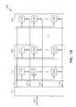
- FIG. 16is an elevational view of a substrate containing semiconductor dies.
- substrateused in the following description may include materials, such as silicon, silicon-on insulator (SOD, silicon-on sapphire (SOS), doped and undoped semiconductors, epitaxial layers of silicon supported by a base semiconductor foundation, silica, ceramic, alumina, metals, organic materials, and other semiconductor structures.
- the semiconductorneed not be silicon-based.
- the semiconductorcould be silicon-germanium, germanium, or gallium arsenide.
- semiconductor wafer fragmentor “wafer fragment” or “wafer” will be understood to mean any construction comprising semiconductor material, including but not limited to, bulk semiconductive materials, such as a semiconductor wafer (either alone or in assemblies comprising other material thereon) and a semiconductive material layer (either alone or in assemblies comprising other materials).
- the terms “cavity”, “well”, and “pre-etched cavity”are used interchangeably throughout this specification.
- active sidemeans the circuit side of a chip.
- chipor “IC chip”, or “semiconductor chip”, or “semiconductor die” will be understood to mean an integrated circuit or other electronic component containing a semiconductor as a base material, and are used interchangeably throughout this specification.
- the build-up multichip packagemay include a memory circuit including an array of memory cells disposed on a substrate and/or a logic circuit including an array of memory cells disposed on a substrate.
- FIGS. 1 , 2 , 3 , 4 , and 5are cross-sectional views of a portion of semiconductor wafer fragment 100 illustrating one embodiment of sequential operations for forming one or more pre-etched cavities 140 on a substrate 110 .
- the operationbegins with a substrate 110 having top and bottom surfaces 112 and 114 as shown in FIG. 1 .
- the substrate 110can include semiconductor-based materials, such as silicon-on insulator (SOD, silicon-on sapphire (SOS), doped and undoped semiconductors, epitaxial layers of silicon supported by a base semiconductor foundation, silica, alumina, ceramic, and/or other semiconductor-based materials.
- the semiconductor-based materialscan also include materials, such as silicon-germanium, germanium, and/or gallium arsenide.
- FIG. 2illustrates deposition of a photoresist layer 120 to mask the top surface 112 of the substrate 110 .
- a suitable photoresist layercomprises photoresist film JSR IX405 made by JSR Microelectronics.
- FIG. 3illustrates exposing and developing photoresist layer 120 to form photoresist pattern 130 .
- Photoresist pattern 130can be developed based on desired shapes and locations for one or more pre-etched cavities 140 as shown in FIG. 4 .
- One or more pre-etched cavities 140can also be one or more wells.
- FIG. 4illustrates etching the photoresist layer 120 including photoresist pattern 130 using a solvent that is selective to photoresist layer 120 to form one or more pre-etched cavities 140 .
- Solventssuch as KOH etchant, wet etchant, and/or dry etchant can be used to etch one or more pre-etched cavities 140 .
- a suitable dry etchcomprises exposing the photoresist layer 120 to CF 4 or C 2 F 6 , among others.
- photoresist layer 120is removed after etching the one or more pre-etched cavities 140 , as shown in FIG. 4 , to expose the formed one or more pre-etched cavities 140 .
- a wet etchantsuch as acetone or s photoresist stripper, such as Shipley's SVC-14 made by Strippers Corporation, among others can be used to remove the photoresist layer 120 .
- Pre-etched cavities 140can also be formed using other conventional processing techniques known to one skilled in the art.
- FIG. 6is a top view of semiconductor wafer fragment 100 shown in FIG. 5 .
- FIG. 6shows alignment marks 160 in addition to one or more pre-etched cavities 140 shown in FIG. 5 .
- the alignment marks 160are disposed around each of the one or more pre-etched cavities 140 .
- Alignment marks 160can also be formed using etching operations described above with reference to FIGS. 4 and 5 .
- alignment marks 160such as those shown in FIG. 6 , are used by pick-and-place machines to aid them in accurately aligning and placing the chips over the one or more pre-etched cavities 140 .
- Alignment marks 160help place the chips substantially accurately in both X and Y dimensions, as well as in holding the chip faces parallel in the same plane.
- Each of the alignment marks 160is disposed at the outer boundaries of the chip placement area of an associated chip to be placed over a cavity 140 as shown in FIG. 6 .
- die-attach material 170is then dispensed in each of the one or more pre-etched cavities 140 .
- the die-attach material 170can include materials such as epoxy, polyimide, polyolefin, and BCB.
- a suitable die-attach materialis a Dexter 536 .
- the die-attach material 170can be dispensed using processes, such as screen-printing, pneumatic dispensing, and positive dispensing. Dispensing equipment, such as a pick-and-place machine, a die-bonder, and/or die-attach equipment can be used to dispense the die-attach material.
- a suitable dispensing machineis a Datacom 2200apm dispensing machine.
- a chip 180is placed over each cavity 140 , including die-attach material 170 , with a slight downward force, as indicated by arrows 185 , such that top surface 187 of each chip 180 is parallel with the top surface 112 of substrate 110 .
- each chip 180is placed over each cavity 140 such that the active surface is on top surface 187 .
- the active surface 187can include one or more contact pads 182 .
- each chipis accurately placed over each cavity using a high accuracy pick-and-place machine, such as the Datacom 2200apm.
- Exemplary chips 180are semiconductor chips, semiconductor dies, semiconductor chips, and IC chips.
- each chip 180is secured to the substrate 110 by curing the dispensed adhesive 170 .
- the dispensed adhesive 170holds each chip 180 in place after curing the adhesive 170 .
- the adhesive 170can be cured using a curing process, such as localized thermal curing, UV light curing (when a glass substrate is used), microwave curing, and/or infrared (IR) curing.
- a curing processsuch as localized thermal curing, UV light curing (when a glass substrate is used), microwave curing, and/or infrared (IR) curing.
- localized thermal or UV light curingcan be used to cure dispensed adhesive 170 in each cavity 140 .
- an encapsulating layer 1000is deposited over the top surfaces of the substrate 112 and chips 187 .
- deposited encapsulating layer 1000is substantially coplanar with the top surfaces of the substrate 112 and chips 187 , because the top surface 187 of each placed chip 180 is substantially coplanar with the top surface 112 of the substrate 110 , which results in consistent chip heights ‘h 1 ’and ‘h 2 ’ as shown in FIG. 9 . Therefore, only a thin encapsulating layer 1000 is needed over the top surfaces of substrate 112 and chips 187 . Thinner encapsulating layer 1000 results in reduced thermal buildup and thermal stress during operation of the multichip module.
- variations in the thickness of the deposited encapsulating layer 1000is considerably reduced due to the substantial coplanarity achieved between the top surfaces of substrate 112 and each of the chips 187 .
- Reduced variation in the thickness of the encapsulating layer 1000results in reduced variations in dielectric properties and post-processing problems, such as metal deposition rate, varying etch rate, and so on, which can ultimately result in a higher yield.
- encapsulating layer 1000is a dielectric layer.
- the dielectric layercan be formed using photo-patternable dielectric materials, such as polyimide, polyolefin, polynorbornene, Benzyl Cyclo Butane (BCB), and Poly Benzoxyzol (PBO).
- dielectric layer 1000is spray or spin coated over the top surfaces of the substrate 112 and each of the chips 187 .
- the thickness of the dielectric layercan be in the range of 1 to 100 microns over the chip surface 187 .
- via holes 1100are formed in the dielectric layer 1000 to expose the at least one or more contact pads 182 at the upper surface 187 of each chip 180 for facilitating electrical connection on the dielectric layer 1000 .
- via holesare formed using an excimer laser.
- metallization structures 1210are formed over the dielectric layer 1000 and the via holes 1100 to interconnect the chips 180 .
- chip interconnection metallization structures 1210are sputtered on the dielectric layer 1000 and via holes 1100 .
- the metallizationis subsequently built up electrolytically and patterned by photolithographic means. Additional interconnection layers are then built up as required by depositing dielectric layer 1000 , forming via holes 1100 , and metallizing structures 1210 .
- I/O structures 1220such as solder bumps and/or gold-plated pad grids are formed over the metallization structures 1210 .
- Gold-plated pad gridis achieved by pattern plating the copper to a thickness of approximately 1 micron or more, followed by plating nickel up to 5 microns and then gold up to 0.5 microns.
- Solder balls, and/or solder paste conesare placed at each site and reflowed to form the desired solder bumps. Note that solder bumps or connection pads can be placed directly above or offset to the side of the bare chips, thus allowing any desired I/O pad array configuration to be produced for the single packaged chip.
- FIG. 13shows another embodiment in which chips 180 are placed inside a second cavity 1320 .
- die-attach materialis dispensed in an earlier operation in a first cavity 1310 .
- first cavity 1310is disposed below the second cavity 1320 .
- first cavity 1310is substantially concentric with the second cavity 1320 . It can be envisioned that first cavity 1310 is offset from second cavity 1320 .
- Second cavity 1320is larger than first cavity 1310 , as shown in FIG. 13 .
- a recessed area 1340similar to a chip placement area around the alignment marks 160 shown in FIGS. 5 and 6 , is formed between the first and second cavities 1310 and 1320 .
- the second cavity 1320is large enough to receive an associated chip 180 .
- second cavity 1320has upwardly extending surfaces 1330 that extend from and around the recessed area 1340 as shown in FIG. 13 .
- the upwardly extending surfaces 1330help in substantially aligning chip 180 in X and Y dimensions during placement of each chip 180 in the second cavity 1320 and over the recessed area 1340 .
- the embodiment shown in FIG. 13requires a substantially reduced thickness of the dielectric layer 1000 over the top surfaces of the substrate 112 and each chip 187 as compared to the embodiment shown in FIG. 12 .
- Each chip 180is placed inside the second cavity 1320 and the chip 180 protrusion beyond the top surface 112 of the substrate 110 can be reduced by controlling the depth ‘d’ of the second cavity 1320 .
- a thinner dielectric layerreduces thermal stress and thermal build-up during operation of the single or multichip module.
- dielectric layers 1000 , via holes 1100 , and metallizing structures 1210are formed over the top surface 112 of the substrate 110 as described above with reference to FIGS. 10-12 . Additional interconnection layers can then be built up as required by depositing dielectric layers 1000 , forming via holes 1100 , metallizing and patterning to form metallizing structures 1210 .
- FIG. 14is a block diagram of a system according to one embodiment of the present invention.
- Computer system 1400contains a processor 1410 and a memory system 1402 housed in a computer unit 1405 .
- Computer system 1400is but one example of an electronic system containing another electronic system, e.g., memory system 1402 , as a subcomponent.
- the memory system 1402includes a memory device that includes a multichip module as discussed in various embodiments of the present invention.
- Computer system 1400optionally contains user interface components. These user interface components include a keyboard 1420 , a pointing device 1430 , a monitor 1440 , a printer 1450 , and a bulk storage device 1460 .
- processor 1410 and memory system 1402 of computer system 1400can be incorporated on a single integrated circuit. Such single-package processing units reduce the communication time between the processor and the memory circuit. Any of these components of the system may contain a multichip module that includes the build-up single or multichip module of the present invention. This is particularly true of graphics subsystem 1470 of FIG. 14 utilizing SGRAM that includes the multiple-mode output driver as discussed in various embodiments of the present invention.
- FIG. 15is a block diagram of a system according to one embodiment of the present invention.
- Memory system 1500contains one or more multichip modules 1502 and a memory controller 1512 .
- Each memory module 1502includes at least one memory device 1510 .
- Memory controller 1512provides and controls a bidirectional interface between memory system 1500 and an external system bus 1520 .
- Memory system 1500accepts a command signal from the external bus 1520 and relays it to the one or more memory modules 1502 on a command link 1530 .
- Memory system 1500provides for data input and data output between the one or more memory modules 1502 and external system bus 1520 on data links 1540 .
- At least one of the memory devices 1510includes the single or multichip modules as discussed in various embodiments of the present invention.
- At least one of the memory devices 1510includes the build-up multichip modules of the present invention.
- a semiconductor die 1610is produced from a silicon wafer 1600 .
- a dieis an individual pattern, typically rectangular, on a substrate that contains circuitry to perform a specific function.
- a semiconductor waferwill typically contain a repeated pattern of such dies containing the same functionality.
- Die 1610may contain multichip modules, as discussed above. Die 1610 may further contain additional circuitry to extend to such complex devices as a monolithic processor with multiple functionality. Die 1610 is typically packaged in single or multichip modules as discussed in various embodiments of the present invention.
- Embodiments of the present inventionprovides techniques for fabricating a multichip module using build-up technology.
- the inventionprovides methods for forming a multichip module using build-up technology to interconnect semiconductor dies.
- the multichip moduleis fabricated by dispensing die-attach material in one or more pre-etched cavities disposed on a substrate.
- a semiconductor dieis then placed over each pre-etched cavity, including the die-attach material, by urging a slight downward pressure to place the semiconductor die to be substantially coplanar with the substrate.
- the semiconductor dieis then secured to the substrate by curing the die-attach material.
- a miniature circuit boardis then formed over the substrate and the secured semiconductor dies by forming a multilayer structure including alternating layers of dielectric and conductive materials that is substantially coplanar with the substrate to electrically interconnect the semiconductor dies.
- the inventionprovides methods for forming a build-up multichip module on a silicon substrate.
- the multichip moduleis formed by dispensing die-attach material in each of one or more first pre-etched cavities disposed on a substrate.
- An IC chipis then placed in each of one or more second pre-etched cavities that are associated with the one or more first pre-etched cavities such that each placed IC chip is disposed over the first pre-etched cavity including the die-attach material.
- a slight downward forceis used while placing each IC chip over the first pre-etched cavities including the die-attach material so that each placed IC chip is substantially coplanar with the substrate.
- each IC chipis substantially accurately aligned by the walls of the second pre-etched cavity while placing the chip in the second pre-etched cavity.
- the placed IC chipsare then secured to the substrate by curing the die-attach material.
- a dielectric layeris then formed over the substrate and the IC chips.
- Metallization structuresare then formed over the dielectric material to electrically interconnect the IC chips.
- the inventionprovides a multichip module.
- the multichip moduleincludes a substrate including one or more chip placement areas. Each chip placement area includes a pre-etched cavity. Each pre-etched cavity includes die-attach material. An IC chip overlies each chip placement area and over the die-attach material such that upper surfaces of the substrate and each IC chip are substantially coplanar.
- a miniature circuit boardincluding multiple layers of dielectric material and metallization structure, overlies the substrate and the IC chips to interconnect the IC chips.
- the inventionprovides a multichip module.
- the multichip moduleincludes a substrate including one or more chip placement areas.
- Each chip placement areaincludes a pre-etched cavity and an associated alignment mark to aid in accurate alignment of a chip during placement of the chip over the chip placement area.
- Each cavityincludes die-attach material.
- An IC chipoverlies each of the one or more chip placement areas and the die-attach material such that the substrate and each IC chip are substantially coplanar.
- a miniature circuit boardincluding multiple alternating layers of dielectric material and metallization structures, overlies the substrate and the IC chips to interconnect the IC chips.
Landscapes
- Engineering & Computer Science (AREA)
- Microelectronics & Electronic Packaging (AREA)
- Power Engineering (AREA)
- Physics & Mathematics (AREA)
- Condensed Matter Physics & Semiconductors (AREA)
- General Physics & Mathematics (AREA)
- Computer Hardware Design (AREA)
- Manufacturing & Machinery (AREA)
- Wire Bonding (AREA)
- Semiconductor Memories (AREA)
- Production Of Multi-Layered Print Wiring Board (AREA)
Abstract
Description
Claims (13)
Priority Applications (1)
| Application Number | Priority Date | Filing Date | Title |
|---|---|---|---|
| US12/642,356US8022536B2 (en) | 2003-02-12 | 2009-12-18 | Semiconductor substrate for build-up packages |
Applications Claiming Priority (3)
| Application Number | Priority Date | Filing Date | Title |
|---|---|---|---|
| US10/365,998US7135780B2 (en) | 2003-02-12 | 2003-02-12 | Semiconductor substrate for build-up packages |
| US11/538,344US7635611B2 (en) | 2003-02-12 | 2006-10-03 | Semiconductor substrate for build-up packages |
| US12/642,356US8022536B2 (en) | 2003-02-12 | 2009-12-18 | Semiconductor substrate for build-up packages |
Related Parent Applications (1)
| Application Number | Title | Priority Date | Filing Date |
|---|---|---|---|
| US11/538,344ContinuationUS7635611B2 (en) | 2003-02-12 | 2006-10-03 | Semiconductor substrate for build-up packages |
Publications (2)
| Publication Number | Publication Date |
|---|---|
| US20100096761A1 US20100096761A1 (en) | 2010-04-22 |
| US8022536B2true US8022536B2 (en) | 2011-09-20 |
Family
ID=32824665
Family Applications (4)
| Application Number | Title | Priority Date | Filing Date |
|---|---|---|---|
| US10/365,998Expired - Fee RelatedUS7135780B2 (en) | 2003-02-12 | 2003-02-12 | Semiconductor substrate for build-up packages |
| US11/003,694Expired - Fee RelatedUS7109063B2 (en) | 2003-02-12 | 2004-12-03 | Semiconductor substrate for build-up packages |
| US11/538,344Expired - LifetimeUS7635611B2 (en) | 2003-02-12 | 2006-10-03 | Semiconductor substrate for build-up packages |
| US12/642,356Expired - LifetimeUS8022536B2 (en) | 2003-02-12 | 2009-12-18 | Semiconductor substrate for build-up packages |
Family Applications Before (3)
| Application Number | Title | Priority Date | Filing Date |
|---|---|---|---|
| US10/365,998Expired - Fee RelatedUS7135780B2 (en) | 2003-02-12 | 2003-02-12 | Semiconductor substrate for build-up packages |
| US11/003,694Expired - Fee RelatedUS7109063B2 (en) | 2003-02-12 | 2004-12-03 | Semiconductor substrate for build-up packages |
| US11/538,344Expired - LifetimeUS7635611B2 (en) | 2003-02-12 | 2006-10-03 | Semiconductor substrate for build-up packages |
Country Status (1)
| Country | Link |
|---|---|
| US (4) | US7135780B2 (en) |
Families Citing this family (35)
| Publication number | Priority date | Publication date | Assignee | Title |
|---|---|---|---|---|
| US7579681B2 (en)* | 2002-06-11 | 2009-08-25 | Micron Technology, Inc. | Super high density module with integrated wafer level packages |
| US6962835B2 (en) | 2003-02-07 | 2005-11-08 | Ziptronix, Inc. | Method for room temperature metal direct bonding |
| US7135780B2 (en) | 2003-02-12 | 2006-11-14 | Micron Technology, Inc. | Semiconductor substrate for build-up packages |
| US7122404B2 (en)* | 2003-03-11 | 2006-10-17 | Micron Technology, Inc. | Techniques for packaging a multiple device component |
| US7145252B2 (en)* | 2003-12-02 | 2006-12-05 | Chi Mei Optoelectronics Corp. | Configuration for testing the bonding positions of conductive drops and test method for using the same |
| US7416788B2 (en)* | 2005-06-30 | 2008-08-26 | Honeywell International Inc. | Thermal barrier coating resistant to penetration by environmental contaminants |
| US7485968B2 (en) | 2005-08-11 | 2009-02-03 | Ziptronix, Inc. | 3D IC method and device |
| TWI263313B (en)* | 2005-08-15 | 2006-10-01 | Phoenix Prec Technology Corp | Stack structure of semiconductor component embedded in supporting board |
| KR100752665B1 (en)* | 2006-06-23 | 2007-08-29 | 삼성전자주식회사 | Semiconductor device using conductive adhesive layer and its manufacturing method |
| CN100552935C (en)* | 2006-10-09 | 2009-10-21 | 日月光半导体制造股份有限公司 | Substrate strip and substrate structure and manufacturing method thereof |
| TWI322495B (en)* | 2006-12-20 | 2010-03-21 | Phoenix Prec Technology Corp | Carrier structure embedded with a chip and method for manufacturing the same |
| US9466561B2 (en) | 2009-08-06 | 2016-10-11 | Rambus Inc. | Packaged semiconductor device for high performance memory and logic |
| JP6103054B2 (en)* | 2013-06-18 | 2017-03-29 | 株式会社村田製作所 | Manufacturing method of resin multilayer substrate |
| US9299651B2 (en)* | 2013-11-20 | 2016-03-29 | Bridge Semiconductor Corporation | Semiconductor assembly and method of manufacturing the same |
| US10886250B2 (en) | 2015-07-10 | 2021-01-05 | Invensas Corporation | Structures and methods for low temperature bonding using nanoparticles |
| US10468363B2 (en) | 2015-08-10 | 2019-11-05 | X-Celeprint Limited | Chiplets with connection posts |
| US9953941B2 (en) | 2015-08-25 | 2018-04-24 | Invensas Bonding Technologies, Inc. | Conductive barrier direct hybrid bonding |
| US11064609B2 (en) | 2016-08-04 | 2021-07-13 | X Display Company Technology Limited | Printable 3D electronic structure |
| TWI822659B (en) | 2016-10-27 | 2023-11-21 | 美商艾德亞半導體科技有限責任公司 | Structures and methods for low temperature bonding |
| TWI647807B (en)* | 2017-01-24 | 2019-01-11 | 旺宏電子股份有限公司 | Interconnect structure and fabricating method thereof |
| US10515913B2 (en) | 2017-03-17 | 2019-12-24 | Invensas Bonding Technologies, Inc. | Multi-metal contact structure |
| US10446441B2 (en) | 2017-06-05 | 2019-10-15 | Invensas Corporation | Flat metal features for microelectronics applications |
| US10840205B2 (en) | 2017-09-24 | 2020-11-17 | Invensas Bonding Technologies, Inc. | Chemical mechanical polishing for hybrid bonding |
| US11056348B2 (en) | 2018-04-05 | 2021-07-06 | Invensas Bonding Technologies, Inc. | Bonding surfaces for microelectronics |
| US10790262B2 (en) | 2018-04-11 | 2020-09-29 | Invensas Bonding Technologies, Inc. | Low temperature bonded structures |
| US11244916B2 (en) | 2018-04-11 | 2022-02-08 | Invensas Bonding Technologies, Inc. | Low temperature bonded structures |
| US11393779B2 (en) | 2018-06-13 | 2022-07-19 | Invensas Bonding Technologies, Inc. | Large metal pads over TSV |
| KR20210009426A (en) | 2018-06-13 | 2021-01-26 | 인벤사스 본딩 테크놀로지스 인코포레이티드 | TV as a pad |
| US11011494B2 (en) | 2018-08-31 | 2021-05-18 | Invensas Bonding Technologies, Inc. | Layer structures for making direct metal-to-metal bonds at low temperatures in microelectronics |
| US11158573B2 (en) | 2018-10-22 | 2021-10-26 | Invensas Bonding Technologies, Inc. | Interconnect structures |
| US11244920B2 (en) | 2018-12-18 | 2022-02-08 | Invensas Bonding Technologies, Inc. | Method and structures for low temperature device bonding |
| WO2021236361A1 (en) | 2020-05-19 | 2021-11-25 | Invensas Bonding Technologies, Inc. | Laterally unconfined structure |
| US11264357B1 (en) | 2020-10-20 | 2022-03-01 | Invensas Corporation | Mixed exposure for large die |
| JP2024501017A (en) | 2020-12-28 | 2024-01-10 | アデイア セミコンダクター ボンディング テクノロジーズ インコーポレイテッド | Structure with through-substrate via and method for forming the same |
| JP2024501559A (en) | 2020-12-30 | 2024-01-12 | アデイア セミコンダクター ボンディング テクノロジーズ インコーポレイテッド | Structures with conductive features and methods of forming the same |
Citations (50)
| Publication number | Priority date | Publication date | Assignee | Title |
|---|---|---|---|---|
| US3903590A (en) | 1973-03-10 | 1975-09-09 | Tokyo Shibaura Electric Co | Multiple chip integrated circuits and method of manufacturing the same |
| US4866501A (en) | 1985-12-16 | 1989-09-12 | American Telephone And Telegraph Company At&T Bell Laboratories | Wafer scale integration |
| US5073814A (en) | 1990-07-02 | 1991-12-17 | General Electric Company | Multi-sublayer dielectric layers |
| US5280192A (en) | 1990-04-30 | 1994-01-18 | International Business Machines Corporation | Three-dimensional memory card structure with internal direct chip attachment |
| US5315486A (en) | 1991-12-16 | 1994-05-24 | General Electric Company | Hermetically packaged HDI electronic system |
| US5324687A (en) | 1992-10-16 | 1994-06-28 | General Electric Company | Method for thinning of integrated circuit chips for lightweight packaged electronic systems |
| US5331203A (en) | 1990-04-05 | 1994-07-19 | General Electric Company | High density interconnect structure including a chamber |
| US5422435A (en) | 1992-05-22 | 1995-06-06 | National Semiconductor Corporation | Stacked multi-chip modules and method of manufacturing |
| US5432677A (en) | 1993-02-09 | 1995-07-11 | Texas Instruments Incorporated | Multi-chip integrated circuit module |
| US5434751A (en) | 1994-04-11 | 1995-07-18 | Martin Marietta Corporation | Reworkable high density interconnect structure incorporating a release layer |
| US5527741A (en) | 1994-10-11 | 1996-06-18 | Martin Marietta Corporation | Fabrication and structures of circuit modules with flexible interconnect layers |
| US5546654A (en) | 1994-08-29 | 1996-08-20 | General Electric Company | Vacuum fixture and method for fabricating electronic assemblies |
| US5565706A (en)* | 1994-03-18 | 1996-10-15 | Hitachi, Ltd. | LSI package board |
| US5745984A (en)* | 1995-07-10 | 1998-05-05 | Martin Marietta Corporation | Method for making an electronic module |
| US5757072A (en) | 1994-12-19 | 1998-05-26 | Martin Marietta Corporation | Structure for protecting air bridges on semiconductor chips from damage |
| US5808874A (en) | 1996-05-02 | 1998-09-15 | Tessera, Inc. | Microelectronic connections with liquid conductive elements |
| US5837427A (en) | 1996-04-30 | 1998-11-17 | Samsung Electro-Mechanics Co Co., Ltd. | Method for manufacturing build-up multi-layer printed circuit board |
| US5841193A (en) | 1996-05-20 | 1998-11-24 | Epic Technologies, Inc. | Single chip modules, repairable multichip modules, and methods of fabrication thereof |
| US5866952A (en) | 1995-11-30 | 1999-02-02 | Lockheed Martin Corporation | High density interconnected circuit module with a compliant layer as part of a stress-reducing molded substrate |
| US5886412A (en) | 1995-08-16 | 1999-03-23 | Micron Technology, Inc. | Angularly offset and recessed stacked die multichip device |
| US5936305A (en) | 1997-11-20 | 1999-08-10 | Micron Technology, Inc. | Stacked leads-over chip multi-chip module |
| US5975408A (en) | 1997-10-23 | 1999-11-02 | Lucent Technologies Inc. | Solder bonding of electrical components |
| US6000127A (en) | 1996-08-08 | 1999-12-14 | Matsushita Electric Industrial Co., Ltd. | Electronic parts mounting method |
| US6057593A (en) | 1996-10-10 | 2000-05-02 | Samsung Electronics Co., Ltd. | Hybrid high-power microwave-frequency integrated circuit |
| US6107121A (en) | 1996-06-24 | 2000-08-22 | International Business Machines Corporation | Method of making interconnections between a multi-layer chip stack to a printed circuit board in a ceramic package |
| US6137183A (en)* | 1997-10-24 | 2000-10-24 | Seiko Epson Corporation | Flip chip mounting method and semiconductor apparatus manufactured by the method |
| US6175161B1 (en) | 1998-05-22 | 2001-01-16 | Alpine Microsystems, Inc. | System and method for packaging integrated circuits |
| US6181569B1 (en) | 1999-06-07 | 2001-01-30 | Kishore K. Chakravorty | Low cost chip size package and method of fabricating the same |
| US6214642B1 (en) | 1997-11-21 | 2001-04-10 | Institute Of Materials Research And Engineering | Area array stud bump flip chip device and assembly process |
| US6274391B1 (en) | 1992-10-26 | 2001-08-14 | Texas Instruments Incorporated | HDI land grid array packaged device having electrical and optical interconnects |
| US20020004257A1 (en) | 2000-03-24 | 2002-01-10 | Yuji Takaoka | Semiconductor device and process for fabricating the same |
| US6368896B2 (en) | 1997-10-31 | 2002-04-09 | Micron Technology, Inc. | Method of wafer level chip scale packaging |
| US6389691B1 (en) | 1995-04-05 | 2002-05-21 | Unitive International Limited | Methods for forming integrated redistribution routing conductors and solder bumps |
| US20020074641A1 (en)* | 2000-12-15 | 2002-06-20 | Steven Towle | Microelectronic package having a bumpless laminated interconnection layer |
| US6423570B1 (en) | 2000-10-18 | 2002-07-23 | Intel Corporation | Method to protect an encapsulated die package during back grinding with a solder metallization layer and devices formed thereby |
| US6506664B1 (en) | 1999-04-02 | 2003-01-14 | Imec Vzw | Method of transferring ultra-thin substrates and application of the method to the manufacture of a multi-layer thin film device |
| US6518163B2 (en) | 1999-12-27 | 2003-02-11 | Fujitsu Limited | Method for forming bumps, semiconductor device, and solder paste |
| US6521530B2 (en) | 1998-11-13 | 2003-02-18 | Fujitsu Limited | Composite interposer and method for producing a composite interposer |
| US20030164548A1 (en)* | 2002-03-04 | 2003-09-04 | Lee Teck Kheng | Flip chip packaging using recessed interposer terminals |
| US6617687B2 (en) | 1999-02-16 | 2003-09-09 | Micron Technology, Inc. | Method of forming a test insert for interfacing a device containing contact bumps with a test substrate |
| US20040043533A1 (en) | 2002-08-27 | 2004-03-04 | Chua Swee Kwang | Multi-chip wafer level system packages and methods of forming same |
| US20040042190A1 (en) | 2002-08-27 | 2004-03-04 | Eng Meow Koon | Multiple chip semiconductor package and method of fabricating same |
| US6709898B1 (en) | 2000-10-04 | 2004-03-23 | Intel Corporation | Die-in-heat spreader microelectronic package |
| US6709897B2 (en) | 2002-01-15 | 2004-03-23 | Unimicron Technology Corp. | Method of forming IC package having upward-facing chip cavity |
| US6734534B1 (en) | 2000-08-16 | 2004-05-11 | Intel Corporation | Microelectronic substrate with integrated devices |
| US6756662B2 (en) | 2002-09-25 | 2004-06-29 | International Business Machines Corporation | Semiconductor chip module and method of manufacture of same |
| US6867499B1 (en) | 1999-09-30 | 2005-03-15 | Skyworks Solutions, Inc. | Semiconductor packaging |
| US20050085014A1 (en) | 2003-02-12 | 2005-04-21 | Micron Technology, Inc. | Semiconductor substrate for build-up packages |
| US6921968B2 (en) | 2003-05-02 | 2005-07-26 | Advance Semiconductor Engineering, Inc. | Stacked flip chip package |
| US6960518B1 (en)* | 2002-07-19 | 2005-11-01 | Taiwan Semiconductor Manufacturing Co., Ltd. | Buildup substrate pad pre-solder bump manufacturing |
Family Cites Families (6)
| Publication number | Priority date | Publication date | Assignee | Title |
|---|---|---|---|---|
| US600127A (en)* | 1898-03-01 | Fare-register | ||
| EP2015359B1 (en) | 1997-05-09 | 2015-12-23 | Citizen Holdings Co., Ltd. | Process for manufacturing a semiconductor package and circuit board substrate |
| JP3560488B2 (en) | 1999-01-29 | 2004-09-02 | ユナイテッド マイクロエレクトロニクス コープ | Chip scale package for multichip |
| JP3876088B2 (en) | 1999-01-29 | 2007-01-31 | ローム株式会社 | Semiconductor chip and multi-chip type semiconductor device |
| US6228687B1 (en) | 1999-06-28 | 2001-05-08 | Micron Technology, Inc. | Wafer-level package and methods of fabricating |
| US6252305B1 (en)* | 2000-02-29 | 2001-06-26 | Advanced Semiconductor Engineering, Inc. | Multichip module having a stacked chip arrangement |
- 2003
- 2003-02-12USUS10/365,998patent/US7135780B2/ennot_activeExpired - Fee Related
- 2004
- 2004-12-03USUS11/003,694patent/US7109063B2/ennot_activeExpired - Fee Related
- 2006
- 2006-10-03USUS11/538,344patent/US7635611B2/ennot_activeExpired - Lifetime
- 2009
- 2009-12-18USUS12/642,356patent/US8022536B2/ennot_activeExpired - Lifetime
Patent Citations (60)
| Publication number | Priority date | Publication date | Assignee | Title |
|---|---|---|---|---|
| US3903590A (en) | 1973-03-10 | 1975-09-09 | Tokyo Shibaura Electric Co | Multiple chip integrated circuits and method of manufacturing the same |
| US4866501A (en) | 1985-12-16 | 1989-09-12 | American Telephone And Telegraph Company At&T Bell Laboratories | Wafer scale integration |
| US5331203A (en) | 1990-04-05 | 1994-07-19 | General Electric Company | High density interconnect structure including a chamber |
| US5280192A (en) | 1990-04-30 | 1994-01-18 | International Business Machines Corporation | Three-dimensional memory card structure with internal direct chip attachment |
| US5073814A (en) | 1990-07-02 | 1991-12-17 | General Electric Company | Multi-sublayer dielectric layers |
| US5315486A (en) | 1991-12-16 | 1994-05-24 | General Electric Company | Hermetically packaged HDI electronic system |
| US5422435A (en) | 1992-05-22 | 1995-06-06 | National Semiconductor Corporation | Stacked multi-chip modules and method of manufacturing |
| US5324687A (en) | 1992-10-16 | 1994-06-28 | General Electric Company | Method for thinning of integrated circuit chips for lightweight packaged electronic systems |
| US6274391B1 (en) | 1992-10-26 | 2001-08-14 | Texas Instruments Incorporated | HDI land grid array packaged device having electrical and optical interconnects |
| US5432677A (en) | 1993-02-09 | 1995-07-11 | Texas Instruments Incorporated | Multi-chip integrated circuit module |
| US5565706A (en)* | 1994-03-18 | 1996-10-15 | Hitachi, Ltd. | LSI package board |
| US5434751A (en) | 1994-04-11 | 1995-07-18 | Martin Marietta Corporation | Reworkable high density interconnect structure incorporating a release layer |
| US5546654A (en) | 1994-08-29 | 1996-08-20 | General Electric Company | Vacuum fixture and method for fabricating electronic assemblies |
| US5527741A (en) | 1994-10-11 | 1996-06-18 | Martin Marietta Corporation | Fabrication and structures of circuit modules with flexible interconnect layers |
| US5757072A (en) | 1994-12-19 | 1998-05-26 | Martin Marietta Corporation | Structure for protecting air bridges on semiconductor chips from damage |
| US6389691B1 (en) | 1995-04-05 | 2002-05-21 | Unitive International Limited | Methods for forming integrated redistribution routing conductors and solder bumps |
| US5745984A (en)* | 1995-07-10 | 1998-05-05 | Martin Marietta Corporation | Method for making an electronic module |
| US5886412A (en) | 1995-08-16 | 1999-03-23 | Micron Technology, Inc. | Angularly offset and recessed stacked die multichip device |
| US5866952A (en) | 1995-11-30 | 1999-02-02 | Lockheed Martin Corporation | High density interconnected circuit module with a compliant layer as part of a stress-reducing molded substrate |
| US5837427A (en) | 1996-04-30 | 1998-11-17 | Samsung Electro-Mechanics Co Co., Ltd. | Method for manufacturing build-up multi-layer printed circuit board |
| US6202298B1 (en) | 1996-05-02 | 2001-03-20 | Tessera, Inc. | Microelectronic connections with liquid conductive elements |
| US5808874A (en) | 1996-05-02 | 1998-09-15 | Tessera, Inc. | Microelectronic connections with liquid conductive elements |
| US6437240B2 (en) | 1996-05-02 | 2002-08-20 | Tessera, Inc. | Microelectronic connections with liquid conductive elements |
| US6159767A (en) | 1996-05-20 | 2000-12-12 | Epic Technologies, Inc. | Single chip modules, repairable multichip modules, and methods of fabrication thereof |
| US5841193A (en) | 1996-05-20 | 1998-11-24 | Epic Technologies, Inc. | Single chip modules, repairable multichip modules, and methods of fabrication thereof |
| US6107121A (en) | 1996-06-24 | 2000-08-22 | International Business Machines Corporation | Method of making interconnections between a multi-layer chip stack to a printed circuit board in a ceramic package |
| US6000127A (en) | 1996-08-08 | 1999-12-14 | Matsushita Electric Industrial Co., Ltd. | Electronic parts mounting method |
| US6057593A (en) | 1996-10-10 | 2000-05-02 | Samsung Electronics Co., Ltd. | Hybrid high-power microwave-frequency integrated circuit |
| US5975408A (en) | 1997-10-23 | 1999-11-02 | Lucent Technologies Inc. | Solder bonding of electrical components |
| US6137183A (en)* | 1997-10-24 | 2000-10-24 | Seiko Epson Corporation | Flip chip mounting method and semiconductor apparatus manufactured by the method |
| US6368896B2 (en) | 1997-10-31 | 2002-04-09 | Micron Technology, Inc. | Method of wafer level chip scale packaging |
| US5936305A (en) | 1997-11-20 | 1999-08-10 | Micron Technology, Inc. | Stacked leads-over chip multi-chip module |
| US6214642B1 (en) | 1997-11-21 | 2001-04-10 | Institute Of Materials Research And Engineering | Area array stud bump flip chip device and assembly process |
| US6175161B1 (en) | 1998-05-22 | 2001-01-16 | Alpine Microsystems, Inc. | System and method for packaging integrated circuits |
| US6521530B2 (en) | 1998-11-13 | 2003-02-18 | Fujitsu Limited | Composite interposer and method for producing a composite interposer |
| US6617687B2 (en) | 1999-02-16 | 2003-09-09 | Micron Technology, Inc. | Method of forming a test insert for interfacing a device containing contact bumps with a test substrate |
| US6506664B1 (en) | 1999-04-02 | 2003-01-14 | Imec Vzw | Method of transferring ultra-thin substrates and application of the method to the manufacture of a multi-layer thin film device |
| US6350668B1 (en) | 1999-06-07 | 2002-02-26 | Kishore K. Chakravorty | Low cost chip size package and method of fabricating the same |
| US6181569B1 (en) | 1999-06-07 | 2001-01-30 | Kishore K. Chakravorty | Low cost chip size package and method of fabricating the same |
| US6867499B1 (en) | 1999-09-30 | 2005-03-15 | Skyworks Solutions, Inc. | Semiconductor packaging |
| US6518163B2 (en) | 1999-12-27 | 2003-02-11 | Fujitsu Limited | Method for forming bumps, semiconductor device, and solder paste |
| US20020004257A1 (en) | 2000-03-24 | 2002-01-10 | Yuji Takaoka | Semiconductor device and process for fabricating the same |
| US6734534B1 (en) | 2000-08-16 | 2004-05-11 | Intel Corporation | Microelectronic substrate with integrated devices |
| US6709898B1 (en) | 2000-10-04 | 2004-03-23 | Intel Corporation | Die-in-heat spreader microelectronic package |
| US6423570B1 (en) | 2000-10-18 | 2002-07-23 | Intel Corporation | Method to protect an encapsulated die package during back grinding with a solder metallization layer and devices formed thereby |
| US6555906B2 (en) | 2000-12-15 | 2003-04-29 | Intel Corporation | Microelectronic package having a bumpless laminated interconnection layer |
| US20020074641A1 (en)* | 2000-12-15 | 2002-06-20 | Steven Towle | Microelectronic package having a bumpless laminated interconnection layer |
| US6709897B2 (en) | 2002-01-15 | 2004-03-23 | Unimicron Technology Corp. | Method of forming IC package having upward-facing chip cavity |
| US20030164548A1 (en)* | 2002-03-04 | 2003-09-04 | Lee Teck Kheng | Flip chip packaging using recessed interposer terminals |
| US6960518B1 (en)* | 2002-07-19 | 2005-11-01 | Taiwan Semiconductor Manufacturing Co., Ltd. | Buildup substrate pad pre-solder bump manufacturing |
| US6964881B2 (en) | 2002-08-27 | 2005-11-15 | Micron Technology, Inc. | Multi-chip wafer level system packages and methods of forming same |
| US20040043533A1 (en) | 2002-08-27 | 2004-03-04 | Chua Swee Kwang | Multi-chip wafer level system packages and methods of forming same |
| US20040042190A1 (en) | 2002-08-27 | 2004-03-04 | Eng Meow Koon | Multiple chip semiconductor package and method of fabricating same |
| US6756662B2 (en) | 2002-09-25 | 2004-06-29 | International Business Machines Corporation | Semiconductor chip module and method of manufacture of same |
| US20050085014A1 (en) | 2003-02-12 | 2005-04-21 | Micron Technology, Inc. | Semiconductor substrate for build-up packages |
| US7109063B2 (en) | 2003-02-12 | 2006-09-19 | Micron Technology, Inc. | Semiconductor substrate for build-up packages |
| US7135780B2 (en) | 2003-02-12 | 2006-11-14 | Micron Technology, Inc. | Semiconductor substrate for build-up packages |
| US20070082429A1 (en) | 2003-02-12 | 2007-04-12 | Micron Technology, Inc. | Semiconductor substrate for build-up packages |
| US7635611B2 (en) | 2003-02-12 | 2009-12-22 | Micron Technology, Inc. | Semiconductor substrate for build-up packages |
| US6921968B2 (en) | 2003-05-02 | 2005-07-26 | Advance Semiconductor Engineering, Inc. | Stacked flip chip package |
Also Published As
| Publication number | Publication date |
|---|---|
| US7635611B2 (en) | 2009-12-22 |
| US20070082429A1 (en) | 2007-04-12 |
| US20040157361A1 (en) | 2004-08-12 |
| US7135780B2 (en) | 2006-11-14 |
| US20100096761A1 (en) | 2010-04-22 |
| US7109063B2 (en) | 2006-09-19 |
| US20050085014A1 (en) | 2005-04-21 |
Similar Documents
| Publication | Publication Date | Title |
|---|---|---|
| US8022536B2 (en) | Semiconductor substrate for build-up packages | |
| US6822324B2 (en) | Wafer-level package with a cavity and fabricating method thereof | |
| US6825553B2 (en) | Multichip wafer level packages and computing systems incorporating same | |
| US6746898B2 (en) | Integrated chip package structure using silicon substrate and method of manufacturing the same | |
| US6051489A (en) | Electronic component package with posts on the active side of the substrate | |
| US7196408B2 (en) | Fan out type wafer level package structure and method of the same | |
| US7208335B2 (en) | Castellated chip-scale packages and methods for fabricating the same | |
| US20080136004A1 (en) | Multi-chip package structure and method of forming the same | |
| US20240379577A1 (en) | Chip package structure and method for forming the same | |
| US20080119029A1 (en) | Wafer scale thin film package | |
| US20030038378A1 (en) | Microelectronic packages including thin film decal and dielectric adhesive layer having conductive vias therein | |
| US20070132082A1 (en) | Copper plating connection for multi-die stack in substrate package | |
| US20230207472A1 (en) | Semiconductor package and manufacturing method of semiconductor package | |
| JP2008211207A (en) | Semiconductor device package having multichip and method thereof | |
| CN112864119A (en) | Integrated circuit package and method of forming the same | |
| WO2019032211A1 (en) | Electronics package having a self-aligning interconnect assembly and method of making same | |
| KR20080077936A (en) | Semiconductor device package and manufacturing method having die receiving through hole and connecting through hole | |
| US6954130B2 (en) | Integrated passive components and package with posts | |
| US7253510B2 (en) | Ball grid array package construction with raised solder ball pads | |
| US7511359B2 (en) | Dual die package with high-speed interconnect | |
| TW202431441A (en) | Layered molded direct contact and dielectric structure and method for making the same | |
| US20100327426A1 (en) | Semiconductor chip package and method of manufacturing the same |
Legal Events
| Date | Code | Title | Description |
|---|---|---|---|
| FEPP | Fee payment procedure | Free format text:PAYOR NUMBER ASSIGNED (ORIGINAL EVENT CODE: ASPN); ENTITY STATUS OF PATENT OWNER: LARGE ENTITY | |
| STCF | Information on status: patent grant | Free format text:PATENTED CASE | |
| FPAY | Fee payment | Year of fee payment:4 | |
| AS | Assignment | Owner name:U.S. BANK NATIONAL ASSOCIATION, AS COLLATERAL AGENT, CALIFORNIA Free format text:SECURITY INTEREST;ASSIGNOR:MICRON TECHNOLOGY, INC.;REEL/FRAME:038669/0001 Effective date:20160426 Owner name:U.S. BANK NATIONAL ASSOCIATION, AS COLLATERAL AGEN Free format text:SECURITY INTEREST;ASSIGNOR:MICRON TECHNOLOGY, INC.;REEL/FRAME:038669/0001 Effective date:20160426 | |
| AS | Assignment | Owner name:MORGAN STANLEY SENIOR FUNDING, INC., AS COLLATERAL AGENT, MARYLAND Free format text:PATENT SECURITY AGREEMENT;ASSIGNOR:MICRON TECHNOLOGY, INC.;REEL/FRAME:038954/0001 Effective date:20160426 Owner name:MORGAN STANLEY SENIOR FUNDING, INC., AS COLLATERAL Free format text:PATENT SECURITY AGREEMENT;ASSIGNOR:MICRON TECHNOLOGY, INC.;REEL/FRAME:038954/0001 Effective date:20160426 | |
| AS | Assignment | Owner name:U.S. BANK NATIONAL ASSOCIATION, AS COLLATERAL AGENT, CALIFORNIA Free format text:CORRECTIVE ASSIGNMENT TO CORRECT THE REPLACE ERRONEOUSLY FILED PATENT #7358718 WITH THE CORRECT PATENT #7358178 PREVIOUSLY RECORDED ON REEL 038669 FRAME 0001. ASSIGNOR(S) HEREBY CONFIRMS THE SECURITY INTEREST;ASSIGNOR:MICRON TECHNOLOGY, INC.;REEL/FRAME:043079/0001 Effective date:20160426 Owner name:U.S. BANK NATIONAL ASSOCIATION, AS COLLATERAL AGEN Free format text:CORRECTIVE ASSIGNMENT TO CORRECT THE REPLACE ERRONEOUSLY FILED PATENT #7358718 WITH THE CORRECT PATENT #7358178 PREVIOUSLY RECORDED ON REEL 038669 FRAME 0001. ASSIGNOR(S) HEREBY CONFIRMS THE SECURITY INTEREST;ASSIGNOR:MICRON TECHNOLOGY, INC.;REEL/FRAME:043079/0001 Effective date:20160426 | |
| AS | Assignment | Owner name:JPMORGAN CHASE BANK, N.A., AS COLLATERAL AGENT, ILLINOIS Free format text:SECURITY INTEREST;ASSIGNORS:MICRON TECHNOLOGY, INC.;MICRON SEMICONDUCTOR PRODUCTS, INC.;REEL/FRAME:047540/0001 Effective date:20180703 Owner name:JPMORGAN CHASE BANK, N.A., AS COLLATERAL AGENT, IL Free format text:SECURITY INTEREST;ASSIGNORS:MICRON TECHNOLOGY, INC.;MICRON SEMICONDUCTOR PRODUCTS, INC.;REEL/FRAME:047540/0001 Effective date:20180703 | |
| AS | Assignment | Owner name:MICRON TECHNOLOGY, INC., IDAHO Free format text:RELEASE BY SECURED PARTY;ASSIGNOR:U.S. BANK NATIONAL ASSOCIATION, AS COLLATERAL AGENT;REEL/FRAME:047243/0001 Effective date:20180629 | |
| MAFP | Maintenance fee payment | Free format text:PAYMENT OF MAINTENANCE FEE, 8TH YEAR, LARGE ENTITY (ORIGINAL EVENT CODE: M1552); ENTITY STATUS OF PATENT OWNER: LARGE ENTITY Year of fee payment:8 | |
| AS | Assignment | Owner name:MICRON TECHNOLOGY, INC., IDAHO Free format text:RELEASE BY SECURED PARTY;ASSIGNOR:MORGAN STANLEY SENIOR FUNDING, INC., AS COLLATERAL AGENT;REEL/FRAME:050937/0001 Effective date:20190731 | |
| AS | Assignment | Owner name:MICRON TECHNOLOGY, INC., IDAHO Free format text:RELEASE BY SECURED PARTY;ASSIGNOR:JPMORGAN CHASE BANK, N.A., AS COLLATERAL AGENT;REEL/FRAME:051028/0001 Effective date:20190731 Owner name:MICRON SEMICONDUCTOR PRODUCTS, INC., IDAHO Free format text:RELEASE BY SECURED PARTY;ASSIGNOR:JPMORGAN CHASE BANK, N.A., AS COLLATERAL AGENT;REEL/FRAME:051028/0001 Effective date:20190731 | |
| MAFP | Maintenance fee payment | Free format text:PAYMENT OF MAINTENANCE FEE, 12TH YEAR, LARGE ENTITY (ORIGINAL EVENT CODE: M1553); ENTITY STATUS OF PATENT OWNER: LARGE ENTITY Year of fee payment:12 |