US8021640B2 - Manufacturing carbon nanotube paper - Google Patents
Manufacturing carbon nanotube paperDownload PDFInfo
- Publication number
- US8021640B2 US8021640B2US12/198,815US19881508AUS8021640B2US 8021640 B2US8021640 B2US 8021640B2US 19881508 AUS19881508 AUS 19881508AUS 8021640 B2US8021640 B2US 8021640B2
- Authority
- US
- United States
- Prior art keywords
- cnt
- colloidal solution
- edge portion
- blade
- sharp edge
- Prior art date
- Legal status (The legal status is an assumption and is not a legal conclusion. Google has not performed a legal analysis and makes no representation as to the accuracy of the status listed.)
- Expired - Fee Related, expires
Links
Images


Classifications
- B—PERFORMING OPERATIONS; TRANSPORTING
- B82—NANOTECHNOLOGY
- B82B—NANOSTRUCTURES FORMED BY MANIPULATION OF INDIVIDUAL ATOMS, MOLECULES, OR LIMITED COLLECTIONS OF ATOMS OR MOLECULES AS DISCRETE UNITS; MANUFACTURE OR TREATMENT THEREOF
- B82B3/00—Manufacture or treatment of nanostructures by manipulation of individual atoms or molecules, or limited collections of atoms or molecules as discrete units
- D—TEXTILES; PAPER
- D21—PAPER-MAKING; PRODUCTION OF CELLULOSE
- D21H—PULP COMPOSITIONS; PREPARATION THEREOF NOT COVERED BY SUBCLASSES D21C OR D21D; IMPREGNATING OR COATING OF PAPER; TREATMENT OF FINISHED PAPER NOT COVERED BY CLASS B31 OR SUBCLASS D21G; PAPER NOT OTHERWISE PROVIDED FOR
- D21H13/00—Pulp or paper, comprising synthetic cellulose or non-cellulose fibres or web-forming material
- D21H13/36—Inorganic fibres or flakes
- D21H13/46—Non-siliceous fibres, e.g. from metal oxides
- D21H13/50—Carbon fibres
- C—CHEMISTRY; METALLURGY
- C01—INORGANIC CHEMISTRY
- C01B—NON-METALLIC ELEMENTS; COMPOUNDS THEREOF; METALLOIDS OR COMPOUNDS THEREOF NOT COVERED BY SUBCLASS C01C
- C01B32/00—Carbon; Compounds thereof
- C01B32/05—Preparation or purification of carbon not covered by groups C01B32/15, C01B32/20, C01B32/25, C01B32/30
- B—PERFORMING OPERATIONS; TRANSPORTING
- B82—NANOTECHNOLOGY
- B82Y—SPECIFIC USES OR APPLICATIONS OF NANOSTRUCTURES; MEASUREMENT OR ANALYSIS OF NANOSTRUCTURES; MANUFACTURE OR TREATMENT OF NANOSTRUCTURES
- B82Y40/00—Manufacture or treatment of nanostructures
- Y—GENERAL TAGGING OF NEW TECHNOLOGICAL DEVELOPMENTS; GENERAL TAGGING OF CROSS-SECTIONAL TECHNOLOGIES SPANNING OVER SEVERAL SECTIONS OF THE IPC; TECHNICAL SUBJECTS COVERED BY FORMER USPC CROSS-REFERENCE ART COLLECTIONS [XRACs] AND DIGESTS
- Y10—TECHNICAL SUBJECTS COVERED BY FORMER USPC
- Y10S—TECHNICAL SUBJECTS COVERED BY FORMER USPC CROSS-REFERENCE ART COLLECTIONS [XRACs] AND DIGESTS
- Y10S977/00—Nanotechnology
- Y10S977/70—Nanostructure
- Y10S977/734—Fullerenes, i.e. graphene-based structures, such as nanohorns, nanococoons, nanoscrolls or fullerene-like structures, e.g. WS2 or MoS2 chalcogenide nanotubes, planar C3N4, etc.
- Y10S977/742—Carbon nanotubes, CNTs
- Y—GENERAL TAGGING OF NEW TECHNOLOGICAL DEVELOPMENTS; GENERAL TAGGING OF CROSS-SECTIONAL TECHNOLOGIES SPANNING OVER SEVERAL SECTIONS OF THE IPC; TECHNICAL SUBJECTS COVERED BY FORMER USPC CROSS-REFERENCE ART COLLECTIONS [XRACs] AND DIGESTS
- Y10—TECHNICAL SUBJECTS COVERED BY FORMER USPC
- Y10S—TECHNICAL SUBJECTS COVERED BY FORMER USPC CROSS-REFERENCE ART COLLECTIONS [XRACs] AND DIGESTS
- Y10S977/00—Nanotechnology
- Y10S977/84—Manufacture, treatment, or detection of nanostructure
- Y10S977/842—Manufacture, treatment, or detection of nanostructure for carbon nanotubes or fullerenes
- Y10S977/845—Purification or separation of fullerenes or nanotubes
Definitions
- the present disclosurerelates generally to carbon nanotubes (CNTs) and, more particularly, to making carbon nanotube (CNT) paper.
- CNTshave attracted attention in many research areas due to their mechanical, thermal, and electrical properties.
- effortshave been made toward the development of new structures containing CNTs.
- FIG. 1is a schematic diagram of an illustrative embodiment of an apparatus for making CNT paper.
- FIG. 2shows an illustrative embodiment of a structure having an edge portion including a relatively sharp edge.
- FIG. 3shows an illustrative embodiment of a structure having an edge portion including a relatively sharp edge and extensions.
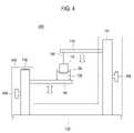
- FIG. 4is a schematic diagram of an illustrative embodiment of an apparatus for making CNT paper.
- FIG. 5is a flowchart of an illustrative embodiment of a method for making a CNT paper.
- FIG. 6shows an illustrative embodiment of an interface between a structure having an edge portion including a relatively sharp edge and a CNT colloidal solution when the structure is being withdrawn from the CNT colloidal solution.
- CNTsmay be assembled to form CNT papers, sheets, wraps, or films having a two-dimensional structure and improved mechanical, electrical, and chemical characteristics.
- CNT papersmay be used in various applications, such as armors, sensors, diodes, polarized light sources, etc.
- FIG. 1is a schematic diagram of an illustrative embodiment of an apparatus 100 for making a CNT paper.
- the apparatus 100may include a structure 110 , a container 120 that may be configured to contain a CNT colloidal solution 130 , and a manipulator 140 that may be configured to dip the structure 110 in and out of the CNT colloidal solution 130 .
- the manipulator 140may be mounted on a base 150 and may include a left guider 142 and a right guider 144 , which may be mounted on the base 150 .
- the manipulator 140may also include a motor unit 146 .
- the motor unit 146may be coupled with the left guider 142 and the right guider 144 via a first shaft 148 and a second shaft 149 , respectively.
- the left guider 142 and the right guider 144may include gears (not shown) that may convert the rotational movements of the first shaft 148 and second shaft 149 , respectively, to vertical translational movements.
- the manipulator 140may be configured to include only one of the first and second shafts 148 , 149 .
- a supporting member 160may be configured to be movably associated with the left guider 142 so that it moves upward or downward along the left guider 142 by operation of the motor unit 146 (via the first shaft 148 ), as illustrated in FIG. 1 .
- the container 120 configured to contain the CNT colloidal solution 130may be placed on the supporting member 160 , and the upward and downward movements of the supporting member 160 may cause the container 120 to move toward or away from the structure 110 .
- the gears of the left guider 142may be configured to move the supporting member 160 upward and downward via a belt-driven mechanism, for example.
- a hanger 170may be mounted to the right guider 144 and may be associated with the structure 110 via a holder 180 .
- the structure 110may be associated with the holder 180 in a detachable manner.
- the hanger 170may be configured to be movably associated with the right guider 144 , so that it may move upward or downward along the right guider 144 by operation of the motor unit 146 (via the second shaft 149 ), as illustrated in FIG. 1 .
- the upward or downward movements of the hanger 170may cause the structure 110 to move toward the container 120 for immersion of the structure 110 in the CNT colloidal solution 130 or move away from the container 120 for withdrawal of the structure 110 from the CNT colloidal solution 130 .
- the supporting member 160 and the hanger 170may be raised and lowered, respectively, at the same time or separately, by operation of the motor unit 146 , so that the structure 110 may be immersed in the CNT colloidal solution 130 .
- the supporting member 160 associated with the left guider 142may remain fixed, while the hanger 170 associated with the right guider 144 may be movable.
- the hanger 170 associated with the right guider 144may remain fixed, while the supporting member 160 associated with the left guider 142 may be movable.
- the motor unit 146may be automatically controlled by a computer or a processor with a processor-readable or computer-readable medium having instructions and programs stored thereon for controlling the operations of the manipulator 140 , such as, for example, the disposing and withdrawal of the structure 110 into and from the CNT colloidal solution 130 , respectively.
- the motor unit 146may be configured to control either the supporting member 160 or the hanger 170 , or both.
- FIG. 2shows an illustrative embodiment of the structure 110 .
- the structure 110may have a body portion 212 , and an edge portion 214 , which may include a relatively sharp edge 215 , and two opposing side edges 216 , 218 .
- the structure 110may resemble a commercially available razor, for example, Dorco ST300 produced and made available by Dorco Korea Co., Ltd. (Seoul, Korea), having a relatively sharp horizontal edge portion.
- the illustrative embodiment depicted in FIG. 2is only being disclosed for illustrative purposes and is not meant to be limiting in any way.
- the edge portion 214may have various other shapes, such as but not limited to, curvy shape, sawtooth shape, etc., as long as it has the relatively sharp edge 215 at the bottom.
- the relatively sharp edge 215 of the edge portion 214may be relatively sharp enough such that CNTs in the CNT colloidal solution 130 may adhere to the relatively sharp edge 215 to form a CNT paper when the structure 110 may be withdrawn from the CNT colloidal solution 130 .
- the relatively sharp edge 215 of the edge portion 214 of the structure 110may have a thickness ranging from about 0.5 nm to about 300 ⁇ m.
- the thicknessmay range from about 1 nm to about 300 ⁇ m, from about 10 nm to about 300 ⁇ m, from about 100 nm to about 300 ⁇ m, from about 1 ⁇ m to about 300 ⁇ m, from about 10 ⁇ m to about 300 ⁇ m, from about 100 ⁇ m to about 300 ⁇ m, from about 0.5 nm to about 100 ⁇ m, from about 0.5 nm to about 10 ⁇ m, from about 0.5 nm to about 1 ⁇ m, from about 0.5 nm to about 100 nm, from about 0.5 nm to about 10 nm, from about 0.5 nm to about 1 nm, from about 1 nm to about 10 nm, from about 10 nm to about 100 nm, from about 100 nm to about 1 ⁇ m, from about 1 ⁇ m to about 10 ⁇ m, or from about 10 ⁇ m to about 100 ⁇ m.
- the thicknessmay be about 0.5 nm, about 1 nm, about 10 nm, about 100 nm, about 1 ⁇ m, about 10 ⁇ m, about 100 ⁇ m, or about 300 ⁇ m.
- the body portion 212 of the structure 110is not limited to a thin plate shape as illustrated in FIG. 2 , but may have, for example, a triangular or trapezoidal plate shape, a lump-like shape, or any other shape such that the body portion 212 may be associated with the edge portion 214 comprising the relatively sharp edge 215 .
- the dimensions of the structure 110may vary depending on the design requirements for the CNT paper.
- the edge portion 214may include a hydrophilic surface property. Most metals, such as, for example, tungsten, may exhibit hydrophilic surface properties and may have good wettability with CNT colloidal solutions.
- the edge portion 214may be formed by etching a metal plate by an anodic oxidation process based on an electrochemical etching method.
- various other materialsmay be included in the edge portion 214 .
- the edge portion 214may include a non-hydrophilic material and a coating that may be hydrophilic.
- the edge portion 214may have a coating of self-assembled monolayers (for example, 16-mercaptohexadecanoic acid or aminoethanethiol).
- FIG. 3shows an illustrative embodiment of a structure 310 including a set of extensions 330 , 330 ′.
- the extensions 330 , 330 ′may be attached to opposing side edges 216 , 218 of the structure 110 shown in FIG. 2 , such that at least a portion of the extensions 330 , 330 ′ may extend lower than the edge portion 214 of the structure 110 .
- Extensions 330 , 330 ′may include body portions, 312 , 312 ′ and edge portions 314 , 314 ′, which may have relatively sharp edges.
- the extensions 330 , 330 ′may resemble a commercially available razor, such as, for example, Dorco ST300.
- the extensions 330 , 330 ′may not include separate edge portions 314 , 314 ′.
- the extensions 330 , 330 ′may be thin plates with no separate edge portions.
- the extensions 330 , 330 ′may be attached to the structure 110 such that the edge portions 314 , 314 ′ of the extensions 330 , 330 ′, respectively, face each other, as illustrated in FIG. 3 .
- the structure 310 including the extensions 330 , 330 ′may be constructed by making the extensions 330 , 330 ′ and the structure 110 separately and subsequently attaching them to each other.
- the structure 310 including the extensions 330 , 330 ′may be formed as a single piece in a single step, such as, for example, by molding.
- the container 120may be a reservoir, which may have a generally rectangular box shape including a horizontal cross section of a generally rectangular shape, and an open top portion.
- the container 120may have a variety of shapes and sizes that may hold the CNT colloidal solution 130 and may be large enough and shaped such that the structure 110 may be received.
- Suitable materials for the container 120may include, but are not limited to, hydrophobic materials such as fluorinated ethylene propylene (TeflonTM), other polytetrafluoroethylene (PTFE) substances, or the like.
- the CNT colloidal solution 130may include CNTs dispersed in a solvent.
- the concentration of the CNTs in the CNT colloidal solution 130may range from about 0.05 mg/ml to about 0.2 mg/ml, from about 0.1 mg/ml to about 0.2 mg/ml, from about 0.15 mg/ml to about 0.2 mg/ml, from about 0.05 mg/ml to about 0.1 mg/ml, from about 0.05 mg/ml to about 0.15 mg/ml, or from about 0.1 mg/ml to about 0.15 mg/ml.
- the concentrationmay be about 0.05 mg/ml, about 0.1 mg/ml, about 0.15 mg/ml or about 0.2 mg/ml.
- the CNT colloidal solution 130may be prepared by dispersing purified CNTs in a solvent, such as deionized water or an organic solvent, for example, 1,2-dichlorobenzene, dimethyl formamide, benzene, methanol, or the like. Since the CNTs produced by conventional methods may contain impurities, the CNTs may be purified before being dispersed into the solution. The purification may be performed by wet oxidation in an acid solution or dry oxidation, for example.
- a solventsuch as deionized water or an organic solvent, for example, 1,2-dichlorobenzene, dimethyl formamide, benzene, methanol, or the like. Since the CNTs produced by conventional methods may contain impurities, the CNTs may be purified before being dispersed into the solution. The purification may be performed by wet oxidation in an acid solution or dry oxidation, for example.
- a suitable purification methodmay include refluxing CNTs in a nitric acid solution (for example, about 2.5 M) and re-suspending the CNTs in water with a surfactant (for example, sodium lauryl sulfate, sodium cholate) at pH 10, and filtering the CNTs using a cross-flow filtration system.
- a surfactantfor example, sodium lauryl sulfate, sodium cholate
- the resulting purified CNT suspensionmay be passed through a filter, such as, for example, a PTFE filter.
- the purified CNTsmay be in a powder form that may be dispersed into the solvent.
- an ultrasonic wave or microwave treatmentmay be carried out to facilitate the dispersion of the purified CNTs throughout the solvent.
- the dispersingmay be carried out in the presence of a surfactant.
- surfactantsincluding, but not limited to, sodium dodecyl sulfate, sodium dodecylbenzenesulfonate, sodium dodecylsulfonate, sodium n-lauroylsarcosinate, sodium alkyl allyl sulfosuccinate, polystyrene sulfonate, dodecyltrimethylammonium bromide, cetyltrimethylammonium bromide, Brij, Tween, Triton X, and poly(vinylpyrrolidone), may be used.
- polymerssuch as epoxy, polyvinylalcohol, polyimide, polystyrene, and polyacrylate, may be added to the CNT colloidal solution.
- Fabricating a CNT paper using a solution containing polymers and CNTsmay be advantageous as the polymers present between the CNTs may have a positive influence on the mechanical properties of the resulting CNT paper, such as, for example, an increase in interfacial shear strength.
- FIG. 4shows a schematic diagram of an illustrative embodiment of an apparatus 400 for making a CNT paper.
- the apparatus 400may include a manipulator 440 that may be configured to dip the structure 110 in and out of the CNT colloidal solution 130 .
- the manipulator 440may include a left handle 490 and a right handle 495 associated with the left guider 142 and the right guider 144 , respectively.
- the left handle 490 and the right handle 495may enable an operator to manually manipulate the supporting member 160 (associated with the left guider 142 ) and the hanger 170 (associated with the right guider 144 ), respectively.
- the left and right handles 490 , 495may be knobs that may be physically connected to the left and right guiders 142 , 144 , respectively, where a rotation or similar manipulation of the handles 490 , 495 may cause the left and right guiders 142 , 144 to move the structure 110 in a substantially downward direction toward the container 120 for immersion of the structure 110 into the CNT colloidal solution 130 or in a substantially upward direction away from the container 120 for withdrawal of the structure 110 from the CNT colloidal solution 130 .
- the apparatus 400may include, in addition to the handles 490 , 495 , a motor unit similar to the one depicted in FIG. 1 .
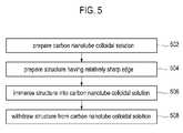
- FIG. 5is a flowchart of an illustrative embodiment of a method for making CNT paper.
- FIG. 5which includes an illustrative embodiment of operational flow, discussion and explanation may be provided with respect to the apparatus and method described herein, and/or with respect to other examples and contexts.
- the CNT colloidal solution 130may be prepared by any of the methods described above.
- the structure 110 having the edge portion 214 including the relatively sharp edge 215may be prepared as described above.
- the structure 110may be disposed into the CNT colloidal solution 130 .
- the operation at block 506may be carried out by moving the structure 110 toward the container 120 , so that the structure 110 may be disposed into the CNT colloidal solution 130 .
- the container 120 containing the CNT colloidal solution 130may be moved toward the structure 110 , so that the structure 110 may be disposed into the CNT colloidal solution 130 .
- both the structure 110 and the container 120may be simultaneously moved toward each other to dispose the structure 110 into the CNT colloidal solution 130 .
- the structure 110may be disposed into the CNT colloidal solution 130 , such that at least the relatively sharp edge 215 of the edge portion 214 of the structure 110 may be fully immersed in the CNT colloidal solution 130 .
- the structure 110may be withdrawn from the CNT colloidal solution 130 , and CNTs in the CNT colloidal solution 130 may adhere to the relatively sharp edge 215 of the edge portion 214 and form a CNT paper.
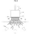
- FIG. 6shows an illustrative embodiment of an interface between the structure 110 having the edge portion 214 including the relatively sharp edge 215 and the CNT colloidal solution 130 when the structure 110 is being withdrawn from the CNT colloidal solution 130 .
- a CNT papermay be formed at the interface between the relatively sharp edge 215 of the edge portion 214 of the structure 110 and the CNT colloidal solution 130 , as the structure 110 may be withdrawn from the CNT colloidal solution 130 .
- an influx flow (V influx ) of CNTs 632may occur toward the structure 110 due to a meniscus 634 whose shape may be determined at least in part by the surface tension force of the CNT colloidal solution 130 .
- the CNTs 632may adhere to the structure 110 and to one another at least partly due to van der Waals forces.
- the influx flow of the CNTs 632may be in the range of about 1 cm/hour to about 9 cm/hour, from about 3 cm/hour to about 9 cm/hour, from about 5 cm/hour to about 9 cm/hour, from about 7 cm/hour to about 9 cm/hour, from about 1 cm/hour to about 3 cm/hour, from about 1 cm/hour to about 5 cm/hour, from about 1 cm/hour to about 7 cm/hour, from about 3 cm/hour to about 5 cm/hour, from about 3 cm/hour to about 7 cm/hour, or from about 5 cm/hour to about 7 cm/hour.
- the influx flowmay be about 1 cm/hour, about 3 cm/hour, about 5 cm/hour, about 7 cm/hour, or about 9 cm/hour.
- a CNT paperthat may be a meso- or macro-scale CNT structure including a large number of the CNTs 632 , may be extended from the relatively sharp edge 215 of the edge portion 214 of the structure 110 .
- the operation at block 508may be carried out, similar to the operation at block 506 , by moving the structure 110 and/or the container 120 to withdraw the structure 110 from the CNT colloidal solution 130 .
- the structure 110may be withdrawn from the CNT colloidal solution 130 at a velocity ranging from about 0.3 mm/min to about 3 mm/min.
- the velocitymay range from about 1 mm/min to about 3 mm/min, from about 2 mm/min to about 3 mm/min, from about 0.3 mm/min to about 1 mm/min, from about 0.3 mm/min to about 2 mm/min, or from about 1 mm/min to about 2 mm/min.
- the velocitymay be about 0.3 mm/min, about 1 mm/min, about 2 mm/min, or about 3 mm/min.
- a sensor(not shown) may be used to determine the specific velocity by which the structure 110 may be withdrawn from the CNT colloidal solution 130 , and a user may control the withdrawal velocity.
- the withdrawal velocity (V W )may be determined at least in part by the viscosity of the CNT colloidal solution 130 . For example, for a higher viscosity of the CNT colloidal solution 130 or a smaller target thickness of the CNT paper, a withdrawal velocity of the structure 110 may be higher.
- the withdrawal velocity of the structure 110may vary or otherwise remain constant.
- the presence of the extensions 330 , 330 ′ in the structure 110may affect the direction of the surface tension force between the structure 110 and the CNT colloidal solution 130 when withdrawing the structure 110 from the CNT colloidal solution 130 , and may prevent the formed CNT paper from slipping from the edge portion 214 of the structure 110 .
- the structure 110may be withdrawn from the CNT colloidal solution 130 at a certain direction relative to the surface of the CNT colloidal solution 130 . In one embodiment, the structure 110 may be withdrawn along a direction substantially perpendicular to the surface of the CNT colloidal solution 130 . In other embodiments, the structure 110 may be withdrawn following a line that is not perpendicular to the surface of the CNT colloidal solution 130 .
- the above operations at block 506 and block 508may be carried out under ambient conditions.
- the disposing and withdrawing of the structure 110 into and from the CNT colloidal solution 130may be carried out at room temperature (for example, about 25° C.), at a relative humidity of about 30%, and at atmospheric pressure (approximately 1 atm).
- room temperaturefor example, about 25° C.
- relative humidityfor example, about 30%
- atmospheric pressureapproximately 1 atm
- the ambient conditionsmay be varied depending on a variety of factors, such as the type of the structure 110 and concentration of the CNT colloidal solution 130 , the target thickness of the CNT paper, etc.
- the operations in block 506 and block 508may be carried out by executing a processor-readable or computer-readable program to control the disposing and the withdrawal of the structure 110 .
- the CNT papers produced by the illustrative embodiments described abovemay have lengths ranging from about 0.5 cm to about 20 cm and thicknesses ranging from about 0.5 nm to about 100 ⁇ m.
- the lengthmay range from about 1 cm to about 20 cm, from about 5 cm to about 20 cm, from about 10 cm to about 20 cm, from about 0.5 cm to about 1 cm, from about 0.5 cm to about 5 cm, from about 0.5 cm to about 10 cm, from about 1 cm to about 5 cm, from about 1 cm to about 10 cm, or from about 5 cm to about 10 cm.
- the lengthmay be about 0.5 cm, about 1 cm, about 5 cm, about 10 cm, or about 20 cm.
- the thicknessmay range from about 1 nm to about 100 ⁇ m, from about 10 nm to about 100 ⁇ m, from about 100 nm to about 100 ⁇ m, from about 1 ⁇ m to about 100 ⁇ m, from about 10 ⁇ m to about 100 ⁇ m, from about 0.5 nm to about 1 nm, from about 0.5 nm to about 10 nm, from about 0.5 nm to about 100 nm, from about 0.5 nm to about 1 ⁇ m, from about 0.5 nm to about 10 ⁇ m, from about 1 nm to about 10 nm, from about 10 nm to about 100 nm, from about 100 nm to about 1 ⁇ m, or from about 1 ⁇ m to about 10 ⁇ m.
- the thicknessesmay be about 0.5 nm, about 1 nm, about 10 nm, about 100 nm, about 1 ⁇ m, about 10 ⁇ m, or about 100 ⁇ m.
- a CNT papermay be further extended by disposing one end of the CNT paper into a CNT colloidal solution and then withdrawing it from the CNT colloidal solution at a certain withdrawing speed. For example, such a process may be repeated more than once to make a CNT paper having a length of about 100 cm or longer.
- the illustrative embodiments described above for making a CNT papermay also be performed with more than one structure 110 in order to mass-produce CNT papers in a simple and efficient manner with high yields.
- the produced CNT papermay also be subjected to various post-treatments including, but without limitation, polymer coating, UV-irradiation, thermal annealing, and electroplating.
- the illustrative embodiments described hereinmay enable the manufacturing of a freestanding CNT paper having a substantially pure, isotropic CNT network without necessarily having other supporting structures.
- the CNT papers formed in accordance with any of the above described embodimentsmay have high porosity, and improved mechanical, electrical and chemical properties.
- a method implemented in softwaremay include computer code to perform the operations of the method.
- This computer codemay be stored in a machine-readable medium, such as a processor-readable medium or a computer program product, or transmitted as a computer data signal embodied in a carrier wave, or a signal modulated by a carrier, over a transmission medium or communication link.
- the machine-readable medium or processor-readable mediummay include any medium capable of storing or transferring information in a form readable and executable by a machine (e.g., by a processor, a computer, etc.).
Landscapes
- Chemical & Material Sciences (AREA)
- Inorganic Chemistry (AREA)
- Engineering & Computer Science (AREA)
- Organic Chemistry (AREA)
- Crystallography & Structural Chemistry (AREA)
- Nanotechnology (AREA)
- Manufacturing & Machinery (AREA)
- Carbon And Carbon Compounds (AREA)
Abstract
Description
Claims (17)
Priority Applications (3)
| Application Number | Priority Date | Filing Date | Title |
|---|---|---|---|
| US12/198,815US8021640B2 (en) | 2008-08-26 | 2008-08-26 | Manufacturing carbon nanotube paper |
| KR1020080122038AKR101172567B1 (en) | 2008-08-26 | 2008-12-03 | Carbon Nanotube Paper Manufacturing |
| US13/210,274US8287695B2 (en) | 2008-08-26 | 2011-08-15 | Manufacturing carbon nanotube paper |
Applications Claiming Priority (1)
| Application Number | Priority Date | Filing Date | Title |
|---|---|---|---|
| US12/198,815US8021640B2 (en) | 2008-08-26 | 2008-08-26 | Manufacturing carbon nanotube paper |
Related Child Applications (1)
| Application Number | Title | Priority Date | Filing Date |
|---|---|---|---|
| US13/210,274DivisionUS8287695B2 (en) | 2008-08-26 | 2011-08-15 | Manufacturing carbon nanotube paper |
Publications (2)
| Publication Number | Publication Date |
|---|---|
| US20100055023A1 US20100055023A1 (en) | 2010-03-04 |
| US8021640B2true US8021640B2 (en) | 2011-09-20 |
Family
ID=41725754
Family Applications (2)
| Application Number | Title | Priority Date | Filing Date |
|---|---|---|---|
| US12/198,815Expired - Fee RelatedUS8021640B2 (en) | 2008-08-26 | 2008-08-26 | Manufacturing carbon nanotube paper |
| US13/210,274ActiveUS8287695B2 (en) | 2008-08-26 | 2011-08-15 | Manufacturing carbon nanotube paper |
Family Applications After (1)
| Application Number | Title | Priority Date | Filing Date |
|---|---|---|---|
| US13/210,274ActiveUS8287695B2 (en) | 2008-08-26 | 2011-08-15 | Manufacturing carbon nanotube paper |
Country Status (2)
| Country | Link |
|---|---|
| US (2) | US8021640B2 (en) |
| KR (1) | KR101172567B1 (en) |
Cited By (6)
| Publication number | Priority date | Publication date | Assignee | Title |
|---|---|---|---|---|
| US20100329502A1 (en)* | 2009-06-26 | 2010-12-30 | Tsinghua University | Bobbin and loudspeaker using the same |
| US20100329501A1 (en)* | 2009-06-26 | 2010-12-30 | Tsinghua University | Bobbin and loudspeaker using the same |
| US20110038505A1 (en)* | 2009-08-11 | 2011-02-17 | Tsinghua University | Bobbin and loudspeaker using the same |
| US10758936B2 (en) | 2015-12-08 | 2020-09-01 | The Boeing Company | Carbon nanomaterial composite sheet and method for making the same |
| US11021368B2 (en) | 2014-07-30 | 2021-06-01 | General Nano Llc | Carbon nanotube sheet structure and method for its making |
| US11021369B2 (en) | 2016-02-04 | 2021-06-01 | General Nano Llc | Carbon nanotube sheet structure and method for its making |
Families Citing this family (7)
| Publication number | Priority date | Publication date | Assignee | Title |
|---|---|---|---|---|
| FI125818B (en)* | 2009-06-08 | 2016-02-29 | Upm Kymmene Corp | Method for making paper |
| FI121890B (en)* | 2009-06-08 | 2011-05-31 | Upm Kymmene Corp | A new type of paper and a process for making it |
| CN102561109A (en)* | 2011-12-20 | 2012-07-11 | 南昌大学 | Method for preparing carbon nano tube conductive paper |
| CN103172044B (en) | 2011-12-21 | 2015-07-01 | 清华大学 | Carbon nanotube paper preparation method |
| CN103178026B (en)* | 2011-12-21 | 2016-03-09 | 清华大学 | Radiator structure and apply the electronic equipment of this radiator structure |
| CN103178027B (en)* | 2011-12-21 | 2016-03-09 | 清华大学 | Radiator structure and apply the electronic equipment of this radiator structure |
| CN111350097B (en)* | 2020-03-30 | 2022-05-03 | 江西克莱威纳米碳材料有限公司 | Preparation method of heating film |
Citations (27)
| Publication number | Priority date | Publication date | Assignee | Title |
|---|---|---|---|---|
| US4841786A (en) | 1986-05-02 | 1989-06-27 | Forschungs-& Entwicklungs-Kg | Specimen distributing system |
| US5763879A (en) | 1996-09-16 | 1998-06-09 | Pacific Western Systems | Diamond probe tip |
| US5948360A (en) | 1994-07-11 | 1999-09-07 | Tekmar Company | Autosampler with robot arm |
| US20020014667A1 (en) | 2000-07-18 | 2002-02-07 | Shin Jin Koog | Method of horizontally growing carbon nanotubes and field effect transistor using the carbon nanotubes grown by the method |
| US20020069505A1 (en)* | 2000-12-07 | 2002-06-13 | Yoshikazu Nakayama And Daiken Chemical Co., Ltd. | Nanotube cartridge and a method for manufacturing the same |
| US20020127162A1 (en)* | 1997-03-07 | 2002-09-12 | William Marsh Rice University | Continuous fiber of single-wall carbon nanotubes |
| US6781166B2 (en) | 1999-07-02 | 2004-08-24 | President & Fellows Of Harvard College | Nanoscopic wire-based devices and arrays |
| US20040265550A1 (en) | 2002-12-06 | 2004-12-30 | Glatkowski Paul J. | Optically transparent nanostructured electrical conductors |
| DE69728410T2 (en) | 1996-08-08 | 2005-05-04 | William Marsh Rice University, Houston | MACROSCOPICALLY MANIPULATED DEVICES MANUFACTURED FROM NANOROE ASSEMBLIES |
| US6905667B1 (en)* | 2002-05-02 | 2005-06-14 | Zyvex Corporation | Polymer and method for using the polymer for noncovalently functionalizing nanotubes |
| US20060060825A1 (en) | 2001-03-26 | 2006-03-23 | Glatkowski Paul J | Coatings comprising carbon nanotubes and methods for forming same |
| US20060099135A1 (en) | 2002-09-10 | 2006-05-11 | Yodh Arjun G | Carbon nanotubes: high solids dispersions and nematic gels thereof |
| US20060274048A1 (en) | 2005-06-02 | 2006-12-07 | Eastman Kodak Company | Touchscreen with conductive layer comprising carbon nanotubes |
| US7147894B2 (en) | 2002-03-25 | 2006-12-12 | The University Of North Carolina At Chapel Hill | Method for assembling nano objects |
| US20070007142A1 (en) | 2002-12-09 | 2007-01-11 | Zhou Otto Z | Methods for assembly and sorting of nanostructure-containing materials and related articles |
| US7164209B1 (en) | 2002-04-02 | 2007-01-16 | Nanosys, Inc. | Methods of positioning and/or orienting nanostructures |
| US20070014148A1 (en) | 2004-05-10 | 2007-01-18 | The University Of North Carolina At Chapel Hill | Methods and systems for attaching a magnetic nanowire to an object and apparatuses formed therefrom |
| US20070020458A1 (en) | 2005-07-25 | 2007-01-25 | National Aeronautics And Space Administration | Carbon nanotube reinforced porous carbon having three-dimensionally ordered porosity and method of fabricating same |
| US20070045119A1 (en) | 2005-09-01 | 2007-03-01 | Micron Technology, Inc. | Methods and apparatus for sorting and/or depositing nanotubes |
| US20070248528A1 (en) | 2003-12-01 | 2007-10-25 | Kim Young N | Method for the Preparation of High Purity Carbon Nanotubes Using Water |
| KR20070112733A (en) | 2006-05-22 | 2007-11-27 | 재단법인서울대학교산학협력재단 | Alignment method of nanostructure and its application method using self-assembly |
| US20080044651A1 (en) | 2004-06-02 | 2008-02-21 | Mysticmd Inc. | Coatings Comprising Carbon Nanotubes |
| US20080044775A1 (en) | 2004-11-12 | 2008-02-21 | Seung-Hun Hong | Method for Aligning or Assembling Nano-Structure on Solid Surface |
| US20080048996A1 (en) | 2006-08-11 | 2008-02-28 | Unidym, Inc. | Touch screen devices employing nanostructure networks |
| US7385295B2 (en) | 2004-06-24 | 2008-06-10 | California Institute Of Technology | Fabrication of nano-gap electrode arrays by the construction and selective chemical etching of nano-crosswire stacks |
| US20080290020A1 (en) | 2006-08-31 | 2008-11-27 | Eva Marand | Method for making oriented single-walled carbon nanotube/;polymer nano-composite membranes |
| US20090059535A1 (en) | 2005-07-05 | 2009-03-05 | Yong-Hyup Kim | Cooling device coated with carbon nanotube and of manufacturing the same |
Family Cites Families (20)
| Publication number | Priority date | Publication date | Assignee | Title |
|---|---|---|---|---|
| JP3536288B2 (en) | 2001-04-05 | 2004-06-07 | 関西ティー・エル・オー株式会社 | Method of manufacturing nanotube probe |
| WO2002088025A1 (en)* | 2001-04-26 | 2002-11-07 | New York University | Method for dissolving carbon nanotubes |
| FR2828500B1 (en) | 2001-08-08 | 2004-08-27 | Centre Nat Rech Scient | PROCESS FOR REFORMING COMPOSITE FIBERS AND APPLICATIONS |
| CN1176014C (en) | 2002-02-22 | 2004-11-17 | 清华大学 | Process for directly synthesizing ultra-long single-wall continuous nano carbon tube |
| CN1281982C (en) | 2002-09-10 | 2006-10-25 | 清华大学 | Polarized element and method for manufacturing same |
| CN100411979C (en) | 2002-09-16 | 2008-08-20 | 清华大学 | A carbon nanotube rope and its manufacturing method |
| GB0226590D0 (en) | 2002-11-14 | 2002-12-24 | Univ Cambridge Tech | Method for producing carbon nanotubes and/or nanofibres |
| CN100537052C (en) | 2002-12-09 | 2009-09-09 | 北卡罗来纳-查佩尔山大学 | Methods for assembling and sorting nanostructure-containing materials and related articles |
| JP4076223B2 (en) | 2003-08-15 | 2008-04-16 | 独立行政法人科学技術振興機構 | Method of joining nanotubes to SPM tip |
| KR100681268B1 (en) | 2004-04-02 | 2007-02-12 | 주식회사 디피아이 솔루션스 | High concentration carbon nanotube aqueous dispersion and preparation method thereof |
| US20050260355A1 (en)* | 2004-05-20 | 2005-11-24 | Jan Weber | Medical devices and methods of making the same |
| US7378040B2 (en) | 2004-08-11 | 2008-05-27 | Eikos, Inc. | Method of forming fluoropolymer binders for carbon nanotube-based transparent conductive coatings |
| US7938996B2 (en) | 2004-10-01 | 2011-05-10 | Board Of Regents, The University Of Texas System | Polymer-free carbon nanotube assemblies (fibers, ropes, ribbons, films) |
| US20060093642A1 (en)* | 2004-11-03 | 2006-05-04 | Ranade Shrirang V | Method of incorporating carbon nanotubes in a medical appliance, a carbon nanotube medical appliance, and a medical appliance coated using carbon nanotube technology |
| KR100781036B1 (en) | 2005-12-31 | 2007-11-29 | 성균관대학교산학협력단 | Apparatus and method for manufacturing carbon nanotube nano probes using metal containers as electrodes |
| KR100790216B1 (en) | 2006-10-17 | 2008-01-02 | 삼성전자주식회사 | CNC Transparent Electrode Using Conductive Dispersant and Manufacturing Method Thereof |
| EP2097928A4 (en) | 2006-12-26 | 2013-07-24 | Texas Southern University | INSTANT ELECTRO-DEPOSITION OF METALLIC NANOSTRUCTURES ON CARBON NANOTUBES |
| KR100907512B1 (en) | 2006-12-29 | 2009-07-14 | (주)탑나노시스 | Method of forming a touch panel and a conductive layer of the touch panel |
| KR100883737B1 (en) | 2007-01-17 | 2009-02-12 | 삼성전자주식회사 | Carbon nanotube transparent electrode comprising a network carbon nanotube thin film layer and a manufacturing method thereof |
| US8673258B2 (en) | 2008-08-14 | 2014-03-18 | Snu R&Db Foundation | Enhanced carbon nanotube |
- 2008
- 2008-08-26USUS12/198,815patent/US8021640B2/ennot_activeExpired - Fee Related
- 2008-12-03KRKR1020080122038Apatent/KR101172567B1/ennot_activeExpired - Fee Related
- 2011
- 2011-08-15USUS13/210,274patent/US8287695B2/enactiveActive
Patent Citations (27)
| Publication number | Priority date | Publication date | Assignee | Title |
|---|---|---|---|---|
| US4841786A (en) | 1986-05-02 | 1989-06-27 | Forschungs-& Entwicklungs-Kg | Specimen distributing system |
| US5948360A (en) | 1994-07-11 | 1999-09-07 | Tekmar Company | Autosampler with robot arm |
| DE69728410T2 (en) | 1996-08-08 | 2005-05-04 | William Marsh Rice University, Houston | MACROSCOPICALLY MANIPULATED DEVICES MANUFACTURED FROM NANOROE ASSEMBLIES |
| US5763879A (en) | 1996-09-16 | 1998-06-09 | Pacific Western Systems | Diamond probe tip |
| US20020127162A1 (en)* | 1997-03-07 | 2002-09-12 | William Marsh Rice University | Continuous fiber of single-wall carbon nanotubes |
| US6781166B2 (en) | 1999-07-02 | 2004-08-24 | President & Fellows Of Harvard College | Nanoscopic wire-based devices and arrays |
| US20020014667A1 (en) | 2000-07-18 | 2002-02-07 | Shin Jin Koog | Method of horizontally growing carbon nanotubes and field effect transistor using the carbon nanotubes grown by the method |
| US20020069505A1 (en)* | 2000-12-07 | 2002-06-13 | Yoshikazu Nakayama And Daiken Chemical Co., Ltd. | Nanotube cartridge and a method for manufacturing the same |
| US20060060825A1 (en) | 2001-03-26 | 2006-03-23 | Glatkowski Paul J | Coatings comprising carbon nanotubes and methods for forming same |
| US7147894B2 (en) | 2002-03-25 | 2006-12-12 | The University Of North Carolina At Chapel Hill | Method for assembling nano objects |
| US7164209B1 (en) | 2002-04-02 | 2007-01-16 | Nanosys, Inc. | Methods of positioning and/or orienting nanostructures |
| US6905667B1 (en)* | 2002-05-02 | 2005-06-14 | Zyvex Corporation | Polymer and method for using the polymer for noncovalently functionalizing nanotubes |
| US20060099135A1 (en) | 2002-09-10 | 2006-05-11 | Yodh Arjun G | Carbon nanotubes: high solids dispersions and nematic gels thereof |
| US20040265550A1 (en) | 2002-12-06 | 2004-12-30 | Glatkowski Paul J. | Optically transparent nanostructured electrical conductors |
| US20070007142A1 (en) | 2002-12-09 | 2007-01-11 | Zhou Otto Z | Methods for assembly and sorting of nanostructure-containing materials and related articles |
| US20070248528A1 (en) | 2003-12-01 | 2007-10-25 | Kim Young N | Method for the Preparation of High Purity Carbon Nanotubes Using Water |
| US20070014148A1 (en) | 2004-05-10 | 2007-01-18 | The University Of North Carolina At Chapel Hill | Methods and systems for attaching a magnetic nanowire to an object and apparatuses formed therefrom |
| US20080044651A1 (en) | 2004-06-02 | 2008-02-21 | Mysticmd Inc. | Coatings Comprising Carbon Nanotubes |
| US7385295B2 (en) | 2004-06-24 | 2008-06-10 | California Institute Of Technology | Fabrication of nano-gap electrode arrays by the construction and selective chemical etching of nano-crosswire stacks |
| US20080044775A1 (en) | 2004-11-12 | 2008-02-21 | Seung-Hun Hong | Method for Aligning or Assembling Nano-Structure on Solid Surface |
| US20060274048A1 (en) | 2005-06-02 | 2006-12-07 | Eastman Kodak Company | Touchscreen with conductive layer comprising carbon nanotubes |
| US20090059535A1 (en) | 2005-07-05 | 2009-03-05 | Yong-Hyup Kim | Cooling device coated with carbon nanotube and of manufacturing the same |
| US20070020458A1 (en) | 2005-07-25 | 2007-01-25 | National Aeronautics And Space Administration | Carbon nanotube reinforced porous carbon having three-dimensionally ordered porosity and method of fabricating same |
| US20070045119A1 (en) | 2005-09-01 | 2007-03-01 | Micron Technology, Inc. | Methods and apparatus for sorting and/or depositing nanotubes |
| KR20070112733A (en) | 2006-05-22 | 2007-11-27 | 재단법인서울대학교산학협력재단 | Alignment method of nanostructure and its application method using self-assembly |
| US20080048996A1 (en) | 2006-08-11 | 2008-02-28 | Unidym, Inc. | Touch screen devices employing nanostructure networks |
| US20080290020A1 (en) | 2006-08-31 | 2008-11-27 | Eva Marand | Method for making oriented single-walled carbon nanotube/;polymer nano-composite membranes |
Non-Patent Citations (41)
| Title |
|---|
| Annamalai, et al., Electrophoretic drawing of continuous fibers of single-walled carbon nanotubes, J. Appl. Phys., 98 114307-1 through 114307-6 (2005). |
| Brioude, et al., "Synthesis of sheathed carbon nanotube tips by the sol-gel technique," Applied Surface Science, 221, 2004, pp. 4-9. |
| Dong, et al., "Synthesis, assembly and device of 1-dimentional nanostructures," Chinese Science Bulletin, 47(14), 2002, pp. 1149-1157. |
| Goldstein et al., "Zero TCR Foil Resistor Ten Fold Improvement in Temperature Coefficient", Electronic Components and Tech. Conf., IEEE, 2001. |
| Hulman et al. , The dielectrophoretic attachent of nanotube fibres on tungsten needles, Mar. 6, 2007, Nanotechnology, 18, 1-5.* |
| Im, et al., "Directed-assembly of Single-walled Carbon Nanotubes Using Self-assembled Monolayer Patterns Comprising Conjugated Molecular Wires," Nanotechnology, (2006) vol. 17: pp. 3569-3573. |
| International Search Report dated Mar. 5, 2009 for corresponding PCT Application No. PCT/KR2008/007144 filed Dec. 3, 2008. |
| International Written Opinion dated Mar. 5, 2009 for corresponding PCT Application No. PCT/KR2008/007144 filed Dec. 3, 2008. |
| Jiang et al., "Spinning continuous carbon nanotube yarns", Nature, vol. 419, 801 (2002). |
| Kaempgen et al., "Transparent carbon nanotube coatings," Applied Surface Science 252; pp. 425-429 (2005). |
| Kang et al. ,Sandwich-type laminated nanocomposites developed by selective dip-coating of carbon nanotubes, Advanced Materials, 2007, 119, 427-432.* |
| Ko et al., "Electrospinning of Continuous Carbon Nanotube-Filled Nanofiber Yarns", Adv. Mater., 15, No. 14, pp. 1161-1165 (2003). |
| Kornev, et al., "Ribbon-to-Fiber Transformation in the Process of Spinning of Carbon-Nanotube Dispersion," Physical Review Letters, 97, 188303-1 through 188303-4, 2006. |
| Kumar et al., "Search for a novel zero thermal expansion material: dilatometry of the Agl-Cul system", J. Mater Sci. 41, pp. 3861-3865 (2006). |
| Kwon et al., "Thermal Contraction of Carbon Fullerenes and Nanotubes", Phy. Rev. Lett., vol. 92, No. 1, pp. 015901-015904 (2004). |
| Kwon, "Computational Modeling and Applications of Carbon Nanotube Devices", NSI Workshop Series-IV, Jul. 11, 2007. |
| Lee et al., "Linker-free directed assembly of high-performance integrated devices based on nanotubes and nanowires", Nature Nanotechnology, vol. 1, pp. 66-71, Oct. 2006. |
| Lewenstein, et al., "High-yield Selective Placement of Carbon Nanotubes on Pre-patterned Electrodes," NanoLetters, (2002) vol. 2, Issue (5): pp. 443-446. |
| Li et al., "Direct Spinning of carbon Nanotube Fibers from Chemical Vapor Deposition Synthesis", Science, vol. 304, 276-278 (2004). |
| Liu et al. , Controlled deposition of individual single-walled carbon nanotubes on chemically functonalize templates, Chemical Physicas Letters, Apr. 2, 1999, 303, 125-129.* |
| Liu et al., "Controlled Growth of Super-Aligned Carbon Nanotube Arrays for Spinning Continuous Unidirectional Sheets with Tunable Physical Properties", NANO Letters, vol. 8, No. 2, pp. 700-705 (2008). |
| Ma et al., "Directly Synthesized Strong, Highly Conducting, Transparent Single-Walled Carbon Nanotube Films," NANO Letters, vol. 7, No. 8, pp. 2307-2311 (2007). |
| Nakagawa, et al., "Controlled Deposition of Silicon Nanowires on Chemically Patterned Substrate by Capillary Force Using a Blade-coating Method," J. Phys. Chem., (2008) vol. 112: pp. 5390-6. |
| Office Action dated Aug. 24, 2010 from U.S. Appl. No. 12/192,024, filed Aug. 14, 2008. |
| Office Action dated Feb. 2, 2010 from U.S. Appl. No. 12/198,835, filed Aug. 26, 2008. |
| Office Action dated Jan. 28, 2010 from U.S. Appl. No. 12/195,347, filed Aug. 20, 2008. |
| Office Action dated Jan. 6, 2011 from U.S. Appl. No. 12/192,024, filed Aug. 14, 2008. |
| Office Action dated Jul. 20, 2009 from U.S. Appl. No. 12/198,835, filed Aug. 26, 2008. |
| Office Action dated Jun. 18, 2010 from U.S. Appl. No. 12/198,835, filed Aug. 26, 2008. |
| Office Action dated Jun. 30, 2009 from U.S. Appl. No. 12/192,024, filed Aug. 14, 2008. |
| Office Action dated Mar. 3, 2011 from U.S. Appl. No. 12/192,024, filed Aug. 14, 2008. |
| Office Action dated May 7, 2010 from U.S. Appl. No. 12/192,024, filed Aug. 14, 2008. |
| Office Action dated Nov. 15, 2010 from U.S. Appl. No. 12/195,347, filed Aug. 20, 2008. |
| Office Action dated Oct. 19, 2009 from U.S. Appl. No. 12/192,024, filed Aug. 14, 2008. |
| Office Action dated Oct. 4, 2010 from U.S. Appl. No. 12/198,835, filed Aug. 26, 2008. |
| Office Action dated Sep. 18, 2009 from U.S. Appl. No. 12/195,347, filed Aug. 20, 2008. |
| Poulin, et al., "Films and fibers of oriented single wall nanotubes," Carbon, 40 (2002) pp. 1741-1749. |
| Rao et al., "Large-scale assembly of carbon nanotubes", Nature, vol. 425, pp. 36-37, Sep. 4, 2003. |
| Tang, et al., "Assembly of 1D Nanostructures into Sub-micrometer Diameter Fibrils with Controlled and Variable Length by Dielectrophoresis," Adv. Mater., 15, No. 16, pp. 1352-1355, 2003. |
| Wang et al., "Controlling the shape, orientation, and linkage of carbon nanotube features with nano affinity templates", PNAS, vol. 103, No. 7, pp. 2026-2031 (2006). |
| Zhang et al., "Multifunctional Carbon Nanotube Yarns by Downsizing an Ancient Technology", Science, vol. 306, 1358-1361 (2004). |
Cited By (9)
| Publication number | Priority date | Publication date | Assignee | Title |
|---|---|---|---|---|
| US20100329502A1 (en)* | 2009-06-26 | 2010-12-30 | Tsinghua University | Bobbin and loudspeaker using the same |
| US20100329501A1 (en)* | 2009-06-26 | 2010-12-30 | Tsinghua University | Bobbin and loudspeaker using the same |
| US8411895B2 (en)* | 2009-06-26 | 2013-04-02 | Tsinghua University | Bobbin and loudspeaker using the same |
| US8422725B2 (en)* | 2009-06-26 | 2013-04-16 | Tsinghua University | Bobbin and loudspeaker using the same |
| US20110038505A1 (en)* | 2009-08-11 | 2011-02-17 | Tsinghua University | Bobbin and loudspeaker using the same |
| US8428296B2 (en)* | 2009-08-11 | 2013-04-23 | Tsinghua University | Bobbin and loudspeaker using the same |
| US11021368B2 (en) | 2014-07-30 | 2021-06-01 | General Nano Llc | Carbon nanotube sheet structure and method for its making |
| US10758936B2 (en) | 2015-12-08 | 2020-09-01 | The Boeing Company | Carbon nanomaterial composite sheet and method for making the same |
| US11021369B2 (en) | 2016-02-04 | 2021-06-01 | General Nano Llc | Carbon nanotube sheet structure and method for its making |
Also Published As
| Publication number | Publication date |
|---|---|
| KR20100024880A (en) | 2010-03-08 |
| US8287695B2 (en) | 2012-10-16 |
| KR101172567B1 (en) | 2012-08-08 |
| US20100055023A1 (en) | 2010-03-04 |
| US20110300031A1 (en) | 2011-12-08 |
Similar Documents
| Publication | Publication Date | Title |
|---|---|---|
| US8021640B2 (en) | Manufacturing carbon nanotube paper | |
| Zhao et al. | Recent advances in the fabrication and structure-specific applications of graphene-based inorganic hybrid membranes | |
| Kim et al. | Large-Area Ti3C2T x-MXene coating: toward industrial-scale fabrication and molecular separation | |
| Martin et al. | Tailored polymer-based nanofibers and nanotubes by means of different infiltration methods into alumina nanopores | |
| US20210086142A1 (en) | Membrane | |
| KR101583593B1 (en) | Nano Porous Films Composed Carbon Nano Structure-Metal Composite or Carbon Nano Structure-Metal Oxide Composite and a process for preparing the same | |
| Razali et al. | Optimisation of polyethersulfone/polyaniline blended membranes using response surface methodology approach | |
| US20160354729A1 (en) | Membranes comprising graphene | |
| US20060207931A1 (en) | Method for continuous fabrication of carbon nanotube networks or membrane materials | |
| Zheng et al. | Facile method toward hierarchical fullerene architectures with enhanced hydrophobicity and photoluminescence | |
| KR101095696B1 (en) | Reinforced carbon nanotube wire | |
| Ding et al. | 2D nanosheets optimized electrospray-assisted interfacial polymerization polyamide membrane with excellent separation performance | |
| KR20100077475A (en) | Fabrication method of gauge like film made up of nano-structured molecules on substrate and substrate with gauge like nano-structured molecules film thereby | |
| KR20160098643A (en) | Fabrication method for electrode using sensor and the sensor thereby | |
| CN110215851B (en) | Graphene hollow fiber membrane with carbon nanotube protective layer and preparation method thereof | |
| Cao et al. | Biomimetic two-dimensional composited membranes for ion separation and desalination | |
| Zhao et al. | Surface modification, topographic design and applications of superhydrophobic systems | |
| KR101085276B1 (en) | Reinforced Carbon Nanotubes | |
| Ali et al. | MXene-based separation membranes for water purification and desalination | |
| Srivastava et al. | Carbon nanotube membrane filters | |
| D'Arcy et al. | Aligned carbon nanotube, graphene and graphite oxide thin films via substrate-directed rapid interfacial deposition | |
| US12403501B2 (en) | Method for forming assembled nanomaterial coating by solute-assisted assembly, and resulting products | |
| Yang et al. | Glycine-Modified Co-MOF Pervaporation Membrane to Enhance Water Transporting | |
| CN107445143A (en) | Method for producing graphene-based materials, obtainable materials and uses thereof | |
| Choi et al. | Fabrication of conducting polymer nanowires |
Legal Events
| Date | Code | Title | Description |
|---|---|---|---|
| AS | Assignment | Owner name:SNU R&DB FOUNDATION,KOREA, REPUBLIC OF Free format text:ASSIGNMENT OF ASSIGNORS INTEREST;ASSIGNORS:KIM, YONG HYUP;JANG, EUI YUN;SIGNING DATES FROM 20081110 TO 20081112;REEL/FRAME:021955/0928 Owner name:SNU R&DB FOUNDATION, KOREA, REPUBLIC OF Free format text:ASSIGNMENT OF ASSIGNORS INTEREST;ASSIGNORS:KIM, YONG HYUP;JANG, EUI YUN;SIGNING DATES FROM 20081110 TO 20081112;REEL/FRAME:021955/0928 | |
| STCF | Information on status: patent grant | Free format text:PATENTED CASE | |
| CC | Certificate of correction | ||
| FPAY | Fee payment | Year of fee payment:4 | |
| FEPP | Fee payment procedure | Free format text:ENTITY STATUS SET TO SMALL (ORIGINAL EVENT CODE: SMAL) | |
| AS | Assignment | Owner name:CRESTLINE DIRECT FINANCE, L.P., TEXAS Free format text:SECURITY INTEREST;ASSIGNOR:EMPIRE TECHNOLOGY DEVELOPMENT LLC;REEL/FRAME:048373/0217 Effective date:20181228 | |
| FEPP | Fee payment procedure | Free format text:MAINTENANCE FEE REMINDER MAILED (ORIGINAL EVENT CODE: REM.); ENTITY STATUS OF PATENT OWNER: SMALL ENTITY | |
| AS | Assignment | Owner name:EMPIRE TECHNOLOGY DEVELOPMENT LLC, WASHINGTON Free format text:RELEASE BY SECURED PARTY;ASSIGNOR:CRESTLINE DIRECT FINANCE, L.P.;REEL/FRAME:049924/0794 Effective date:20190501 | |
| LAPS | Lapse for failure to pay maintenance fees | Free format text:PATENT EXPIRED FOR FAILURE TO PAY MAINTENANCE FEES (ORIGINAL EVENT CODE: EXP.); ENTITY STATUS OF PATENT OWNER: SMALL ENTITY | |
| STCH | Information on status: patent discontinuation | Free format text:PATENT EXPIRED DUE TO NONPAYMENT OF MAINTENANCE FEES UNDER 37 CFR 1.362 | |
| FP | Lapsed due to failure to pay maintenance fee | Effective date:20190920 |