US8021428B2 - Ceramic disc prosthesis - Google Patents
Ceramic disc prosthesisDownload PDFInfo
- Publication number
- US8021428B2 US8021428B2US10/908,766US90876605AUS8021428B2US 8021428 B2US8021428 B2US 8021428B2US 90876605 AUS90876605 AUS 90876605AUS 8021428 B2US8021428 B2US 8021428B2
- Authority
- US
- United States
- Prior art keywords
- bone
- endplates
- attachment element
- disc
- ceramic
- Prior art date
- Legal status (The legal status is an assumption and is not a legal conclusion. Google has not performed a legal analysis and makes no representation as to the accuracy of the status listed.)
- Expired - Fee Related, expires
Links
- 239000000919ceramicSubstances0.000titleclaimsabstractdescription24
- 210000000988bone and boneAnatomy0.000claimsabstractdescription179
- 229910010293ceramic materialInorganic materials0.000claimsabstractdescription19
- 230000000295complement effectEffects0.000claimsabstractdescription7
- 230000013011matingEffects0.000claimsdescription21
- 230000000149penetrating effectEffects0.000claimsdescription19
- 238000003780insertionMethods0.000claimsdescription18
- 230000037431insertionEffects0.000claimsdescription18
- 239000000463materialSubstances0.000claimsdescription13
- 238000000576coating methodMethods0.000claimsdescription10
- 239000012781shape memory materialSubstances0.000claimsdescription10
- 239000011248coating agentSubstances0.000claimsdescription9
- 238000000034methodMethods0.000claimsdescription7
- 230000004913activationEffects0.000claimsdescription5
- 229910052751metalInorganic materials0.000claimsdescription5
- 239000002184metalSubstances0.000claimsdescription5
- 239000004033plasticSubstances0.000claimsdescription5
- 229920003023plasticPolymers0.000claimsdescription5
- 238000005219brazingMethods0.000claimsdescription3
- 238000003384imaging methodMethods0.000description11
- 230000002980postoperative effectEffects0.000description9
- RTAQQCXQSZGOHL-UHFFFAOYSA-NTitaniumChemical compound[Ti]RTAQQCXQSZGOHL-UHFFFAOYSA-N0.000description5
- 230000006378damageEffects0.000description5
- 210000001519tissueAnatomy0.000description5
- 239000010936titaniumSubstances0.000description5
- 229910052719titaniumInorganic materials0.000description5
- 230000003213activating effectEffects0.000description4
- 239000007943implantSubstances0.000description3
- 229910001000nickel titaniumInorganic materials0.000description3
- MCMNRKCIXSYSNV-UHFFFAOYSA-NZirconium dioxideChemical compoundO=[Zr]=OMCMNRKCIXSYSNV-UHFFFAOYSA-N0.000description2
- 239000000853adhesiveSubstances0.000description2
- 230000001070adhesive effectEffects0.000description2
- 210000003484anatomyAnatomy0.000description2
- 238000005452bendingMethods0.000description2
- 230000036760body temperatureEffects0.000description2
- 230000007850degenerationEffects0.000description2
- 238000013461designMethods0.000description2
- -1for exampleSubstances0.000description2
- 230000006870functionEffects0.000description2
- 238000002513implantationMethods0.000description2
- 208000014674injuryDiseases0.000description2
- 230000007246mechanismEffects0.000description2
- HLXZNVUGXRDIFK-UHFFFAOYSA-Nnickel titaniumChemical compound[Ti].[Ti].[Ti].[Ti].[Ti].[Ti].[Ti].[Ti].[Ti].[Ti].[Ti].[Ni].[Ni].[Ni].[Ni].[Ni].[Ni].[Ni].[Ni].[Ni].[Ni].[Ni].[Ni].[Ni].[Ni]HLXZNVUGXRDIFK-UHFFFAOYSA-N0.000description2
- 230000008569processEffects0.000description2
- 230000000153supplemental effectEffects0.000description2
- 230000008733traumaEffects0.000description2
- 239000004593EpoxySubstances0.000description1
- HZEWFHLRYVTOIW-UHFFFAOYSA-N[Ti].[Ni]Chemical compound[Ti].[Ni]HZEWFHLRYVTOIW-UHFFFAOYSA-N0.000description1
- 230000009471actionEffects0.000description1
- 239000011149active materialSubstances0.000description1
- PNEYBMLMFCGWSK-UHFFFAOYSA-Naluminium oxideInorganic materials[O-2].[O-2].[O-2].[Al+3].[Al+3]PNEYBMLMFCGWSK-UHFFFAOYSA-N0.000description1
- 238000013459approachMethods0.000description1
- 239000011324beadSubstances0.000description1
- 230000006399behaviorEffects0.000description1
- 239000011230binding agentSubstances0.000description1
- 239000000560biocompatible materialSubstances0.000description1
- 239000002639bone cementSubstances0.000description1
- 230000008468bone growthEffects0.000description1
- 229910000389calcium phosphateInorganic materials0.000description1
- 239000001506calcium phosphateSubstances0.000description1
- 235000011010calcium phosphatesNutrition0.000description1
- 239000004918carbon fiber reinforced polymerSubstances0.000description1
- 238000006243chemical reactionMethods0.000description1
- 230000006835compressionEffects0.000description1
- 238000007906compressionMethods0.000description1
- 230000002950deficientEffects0.000description1
- 201000010099diseaseDiseases0.000description1
- 208000037265diseases, disorders, signs and symptomsDiseases0.000description1
- 238000006073displacement reactionMethods0.000description1
- 230000004927fusionEffects0.000description1
- 230000036541healthEffects0.000description1
- 229910052588hydroxylapatiteInorganic materials0.000description1
- 238000001727in vivoMethods0.000description1
- 229910000765intermetallicInorganic materials0.000description1
- 210000003041ligamentAnatomy0.000description1
- 238000002595magnetic resonance imagingMethods0.000description1
- 238000004519manufacturing processMethods0.000description1
- 150000002739metalsChemical class0.000description1
- 230000005012migrationEffects0.000description1
- 238000013508migrationMethods0.000description1
- 239000000203mixtureSubstances0.000description1
- 238000012986modificationMethods0.000description1
- 230000004048modificationEffects0.000description1
- 230000003349osteoarthritic effectEffects0.000description1
- 239000002245particleSubstances0.000description1
- XYJRXVWERLGGKC-UHFFFAOYSA-Dpentacalcium;hydroxide;triphosphateChemical compound[OH-].[Ca+2].[Ca+2].[Ca+2].[Ca+2].[Ca+2].[O-]P([O-])([O-])=O.[O-]P([O-])([O-])=O.[O-]P([O-])([O-])=OXYJRXVWERLGGKC-UHFFFAOYSA-D0.000description1
- 229920002530polyetherether ketonePolymers0.000description1
- 229920000642polymerPolymers0.000description1
- 210000004872soft tissueAnatomy0.000description1
- 229910001220stainless steelInorganic materials0.000description1
- 239000010935stainless steelSubstances0.000description1
- QORWJWZARLRLPR-UHFFFAOYSA-Htricalcium bis(phosphate)Chemical compound[Ca+2].[Ca+2].[Ca+2].[O-]P([O-])([O-])=O.[O-]P([O-])([O-])=OQORWJWZARLRLPR-UHFFFAOYSA-H0.000description1
- RUDFQVOCFDJEEF-UHFFFAOYSA-Nyttrium(III) oxideInorganic materials[O-2].[O-2].[O-2].[Y+3].[Y+3]RUDFQVOCFDJEEF-UHFFFAOYSA-N0.000description1
Images


Classifications
- A—HUMAN NECESSITIES
- A61—MEDICAL OR VETERINARY SCIENCE; HYGIENE
- A61F—FILTERS IMPLANTABLE INTO BLOOD VESSELS; PROSTHESES; DEVICES PROVIDING PATENCY TO, OR PREVENTING COLLAPSING OF, TUBULAR STRUCTURES OF THE BODY, e.g. STENTS; ORTHOPAEDIC, NURSING OR CONTRACEPTIVE DEVICES; FOMENTATION; TREATMENT OR PROTECTION OF EYES OR EARS; BANDAGES, DRESSINGS OR ABSORBENT PADS; FIRST-AID KITS
- A61F2/00—Filters implantable into blood vessels; Prostheses, i.e. artificial substitutes or replacements for parts of the body; Appliances for connecting them with the body; Devices providing patency to, or preventing collapsing of, tubular structures of the body, e.g. stents
- A61F2/02—Prostheses implantable into the body
- A61F2/30—Joints
- A61F2/44—Joints for the spine, e.g. vertebrae, spinal discs
- A61F2/442—Intervertebral or spinal discs, e.g. resilient
- A61F2/4425—Intervertebral or spinal discs, e.g. resilient made of articulated components
- A—HUMAN NECESSITIES
- A61—MEDICAL OR VETERINARY SCIENCE; HYGIENE
- A61F—FILTERS IMPLANTABLE INTO BLOOD VESSELS; PROSTHESES; DEVICES PROVIDING PATENCY TO, OR PREVENTING COLLAPSING OF, TUBULAR STRUCTURES OF THE BODY, e.g. STENTS; ORTHOPAEDIC, NURSING OR CONTRACEPTIVE DEVICES; FOMENTATION; TREATMENT OR PROTECTION OF EYES OR EARS; BANDAGES, DRESSINGS OR ABSORBENT PADS; FIRST-AID KITS
- A61F2/00—Filters implantable into blood vessels; Prostheses, i.e. artificial substitutes or replacements for parts of the body; Appliances for connecting them with the body; Devices providing patency to, or preventing collapsing of, tubular structures of the body, e.g. stents
- A61F2/02—Prostheses implantable into the body
- A61F2/30—Joints
- A61F2/30767—Special external or bone-contacting surface, e.g. coating for improving bone ingrowth
- A—HUMAN NECESSITIES
- A61—MEDICAL OR VETERINARY SCIENCE; HYGIENE
- A61F—FILTERS IMPLANTABLE INTO BLOOD VESSELS; PROSTHESES; DEVICES PROVIDING PATENCY TO, OR PREVENTING COLLAPSING OF, TUBULAR STRUCTURES OF THE BODY, e.g. STENTS; ORTHOPAEDIC, NURSING OR CONTRACEPTIVE DEVICES; FOMENTATION; TREATMENT OR PROTECTION OF EYES OR EARS; BANDAGES, DRESSINGS OR ABSORBENT PADS; FIRST-AID KITS
- A61F2/00—Filters implantable into blood vessels; Prostheses, i.e. artificial substitutes or replacements for parts of the body; Appliances for connecting them with the body; Devices providing patency to, or preventing collapsing of, tubular structures of the body, e.g. stents
- A61F2/02—Prostheses implantable into the body
- A61F2/30—Joints
- A61F2/3094—Designing or manufacturing processes
- A61F2/30965—Reinforcing the prosthesis by embedding particles or fibres during moulding or dipping
- A—HUMAN NECESSITIES
- A61—MEDICAL OR VETERINARY SCIENCE; HYGIENE
- A61F—FILTERS IMPLANTABLE INTO BLOOD VESSELS; PROSTHESES; DEVICES PROVIDING PATENCY TO, OR PREVENTING COLLAPSING OF, TUBULAR STRUCTURES OF THE BODY, e.g. STENTS; ORTHOPAEDIC, NURSING OR CONTRACEPTIVE DEVICES; FOMENTATION; TREATMENT OR PROTECTION OF EYES OR EARS; BANDAGES, DRESSINGS OR ABSORBENT PADS; FIRST-AID KITS
- A61F2/00—Filters implantable into blood vessels; Prostheses, i.e. artificial substitutes or replacements for parts of the body; Appliances for connecting them with the body; Devices providing patency to, or preventing collapsing of, tubular structures of the body, e.g. stents
- A61F2/02—Prostheses implantable into the body
- A61F2/30—Joints
- A61F2/46—Special tools for implanting artificial joints
- A61F2/4603—Special tools for implanting artificial joints for insertion or extraction of endoprosthetic joints or of accessories thereof
- A61F2/4611—Special tools for implanting artificial joints for insertion or extraction of endoprosthetic joints or of accessories thereof of spinal prostheses
- A—HUMAN NECESSITIES
- A61—MEDICAL OR VETERINARY SCIENCE; HYGIENE
- A61F—FILTERS IMPLANTABLE INTO BLOOD VESSELS; PROSTHESES; DEVICES PROVIDING PATENCY TO, OR PREVENTING COLLAPSING OF, TUBULAR STRUCTURES OF THE BODY, e.g. STENTS; ORTHOPAEDIC, NURSING OR CONTRACEPTIVE DEVICES; FOMENTATION; TREATMENT OR PROTECTION OF EYES OR EARS; BANDAGES, DRESSINGS OR ABSORBENT PADS; FIRST-AID KITS
- A61F2/00—Filters implantable into blood vessels; Prostheses, i.e. artificial substitutes or replacements for parts of the body; Appliances for connecting them with the body; Devices providing patency to, or preventing collapsing of, tubular structures of the body, e.g. stents
- A61F2/02—Prostheses implantable into the body
- A61F2/30—Joints
- A61F2002/30001—Additional features of subject-matter classified in A61F2/28, A61F2/30 and subgroups thereof
- A61F2002/30003—Material related properties of the prosthesis or of a coating on the prosthesis
- A61F2002/3006—Properties of materials and coating materials
- A61F2002/30092—Properties of materials and coating materials using shape memory or superelastic materials, e.g. nitinol
- A—HUMAN NECESSITIES
- A61—MEDICAL OR VETERINARY SCIENCE; HYGIENE
- A61F—FILTERS IMPLANTABLE INTO BLOOD VESSELS; PROSTHESES; DEVICES PROVIDING PATENCY TO, OR PREVENTING COLLAPSING OF, TUBULAR STRUCTURES OF THE BODY, e.g. STENTS; ORTHOPAEDIC, NURSING OR CONTRACEPTIVE DEVICES; FOMENTATION; TREATMENT OR PROTECTION OF EYES OR EARS; BANDAGES, DRESSINGS OR ABSORBENT PADS; FIRST-AID KITS
- A61F2/00—Filters implantable into blood vessels; Prostheses, i.e. artificial substitutes or replacements for parts of the body; Appliances for connecting them with the body; Devices providing patency to, or preventing collapsing of, tubular structures of the body, e.g. stents
- A61F2/02—Prostheses implantable into the body
- A61F2/30—Joints
- A61F2002/30001—Additional features of subject-matter classified in A61F2/28, A61F2/30 and subgroups thereof
- A61F2002/30108—Shapes
- A61F2002/3011—Cross-sections or two-dimensional shapes
- A61F2002/30159—Concave polygonal shapes
- A61F2002/30179—X-shaped
- A—HUMAN NECESSITIES
- A61—MEDICAL OR VETERINARY SCIENCE; HYGIENE
- A61F—FILTERS IMPLANTABLE INTO BLOOD VESSELS; PROSTHESES; DEVICES PROVIDING PATENCY TO, OR PREVENTING COLLAPSING OF, TUBULAR STRUCTURES OF THE BODY, e.g. STENTS; ORTHOPAEDIC, NURSING OR CONTRACEPTIVE DEVICES; FOMENTATION; TREATMENT OR PROTECTION OF EYES OR EARS; BANDAGES, DRESSINGS OR ABSORBENT PADS; FIRST-AID KITS
- A61F2/00—Filters implantable into blood vessels; Prostheses, i.e. artificial substitutes or replacements for parts of the body; Appliances for connecting them with the body; Devices providing patency to, or preventing collapsing of, tubular structures of the body, e.g. stents
- A61F2/02—Prostheses implantable into the body
- A61F2/30—Joints
- A61F2002/30001—Additional features of subject-matter classified in A61F2/28, A61F2/30 and subgroups thereof
- A61F2002/30316—The prosthesis having different structural features at different locations within the same prosthesis; Connections between prosthetic parts; Special structural features of bone or joint prostheses not otherwise provided for
- A61F2002/30329—Connections or couplings between prosthetic parts, e.g. between modular parts; Connecting elements
- A61F2002/30476—Connections or couplings between prosthetic parts, e.g. between modular parts; Connecting elements locked by an additional locking mechanism
- A61F2002/305—Snap connection
- A—HUMAN NECESSITIES
- A61—MEDICAL OR VETERINARY SCIENCE; HYGIENE
- A61F—FILTERS IMPLANTABLE INTO BLOOD VESSELS; PROSTHESES; DEVICES PROVIDING PATENCY TO, OR PREVENTING COLLAPSING OF, TUBULAR STRUCTURES OF THE BODY, e.g. STENTS; ORTHOPAEDIC, NURSING OR CONTRACEPTIVE DEVICES; FOMENTATION; TREATMENT OR PROTECTION OF EYES OR EARS; BANDAGES, DRESSINGS OR ABSORBENT PADS; FIRST-AID KITS
- A61F2/00—Filters implantable into blood vessels; Prostheses, i.e. artificial substitutes or replacements for parts of the body; Appliances for connecting them with the body; Devices providing patency to, or preventing collapsing of, tubular structures of the body, e.g. stents
- A61F2/02—Prostheses implantable into the body
- A61F2/30—Joints
- A61F2002/30001—Additional features of subject-matter classified in A61F2/28, A61F2/30 and subgroups thereof
- A61F2002/30316—The prosthesis having different structural features at different locations within the same prosthesis; Connections between prosthetic parts; Special structural features of bone or joint prostheses not otherwise provided for
- A61F2002/30535—Special structural features of bone or joint prostheses not otherwise provided for
- A61F2002/30561—Special structural features of bone or joint prostheses not otherwise provided for breakable or frangible
- A—HUMAN NECESSITIES
- A61—MEDICAL OR VETERINARY SCIENCE; HYGIENE
- A61F—FILTERS IMPLANTABLE INTO BLOOD VESSELS; PROSTHESES; DEVICES PROVIDING PATENCY TO, OR PREVENTING COLLAPSING OF, TUBULAR STRUCTURES OF THE BODY, e.g. STENTS; ORTHOPAEDIC, NURSING OR CONTRACEPTIVE DEVICES; FOMENTATION; TREATMENT OR PROTECTION OF EYES OR EARS; BANDAGES, DRESSINGS OR ABSORBENT PADS; FIRST-AID KITS
- A61F2/00—Filters implantable into blood vessels; Prostheses, i.e. artificial substitutes or replacements for parts of the body; Appliances for connecting them with the body; Devices providing patency to, or preventing collapsing of, tubular structures of the body, e.g. stents
- A61F2/02—Prostheses implantable into the body
- A61F2/30—Joints
- A61F2002/30001—Additional features of subject-matter classified in A61F2/28, A61F2/30 and subgroups thereof
- A61F2002/30316—The prosthesis having different structural features at different locations within the same prosthesis; Connections between prosthetic parts; Special structural features of bone or joint prostheses not otherwise provided for
- A61F2002/30535—Special structural features of bone or joint prostheses not otherwise provided for
- A61F2002/30579—Special structural features of bone or joint prostheses not otherwise provided for with mechanically expandable devices, e.g. fixation devices
- A—HUMAN NECESSITIES
- A61—MEDICAL OR VETERINARY SCIENCE; HYGIENE
- A61F—FILTERS IMPLANTABLE INTO BLOOD VESSELS; PROSTHESES; DEVICES PROVIDING PATENCY TO, OR PREVENTING COLLAPSING OF, TUBULAR STRUCTURES OF THE BODY, e.g. STENTS; ORTHOPAEDIC, NURSING OR CONTRACEPTIVE DEVICES; FOMENTATION; TREATMENT OR PROTECTION OF EYES OR EARS; BANDAGES, DRESSINGS OR ABSORBENT PADS; FIRST-AID KITS
- A61F2/00—Filters implantable into blood vessels; Prostheses, i.e. artificial substitutes or replacements for parts of the body; Appliances for connecting them with the body; Devices providing patency to, or preventing collapsing of, tubular structures of the body, e.g. stents
- A61F2/02—Prostheses implantable into the body
- A61F2/30—Joints
- A61F2002/30001—Additional features of subject-matter classified in A61F2/28, A61F2/30 and subgroups thereof
- A61F2002/30621—Features concerning the anatomical functioning or articulation of the prosthetic joint
- A61F2002/30649—Ball-and-socket joints
- A—HUMAN NECESSITIES
- A61—MEDICAL OR VETERINARY SCIENCE; HYGIENE
- A61F—FILTERS IMPLANTABLE INTO BLOOD VESSELS; PROSTHESES; DEVICES PROVIDING PATENCY TO, OR PREVENTING COLLAPSING OF, TUBULAR STRUCTURES OF THE BODY, e.g. STENTS; ORTHOPAEDIC, NURSING OR CONTRACEPTIVE DEVICES; FOMENTATION; TREATMENT OR PROTECTION OF EYES OR EARS; BANDAGES, DRESSINGS OR ABSORBENT PADS; FIRST-AID KITS
- A61F2/00—Filters implantable into blood vessels; Prostheses, i.e. artificial substitutes or replacements for parts of the body; Appliances for connecting them with the body; Devices providing patency to, or preventing collapsing of, tubular structures of the body, e.g. stents
- A61F2/02—Prostheses implantable into the body
- A61F2/30—Joints
- A61F2/30767—Special external or bone-contacting surface, e.g. coating for improving bone ingrowth
- A61F2/30771—Special external or bone-contacting surface, e.g. coating for improving bone ingrowth applied in original prostheses, e.g. holes or grooves
- A61F2002/30841—Sharp anchoring protrusions for impaction into the bone, e.g. sharp pins, spikes
- A—HUMAN NECESSITIES
- A61—MEDICAL OR VETERINARY SCIENCE; HYGIENE
- A61F—FILTERS IMPLANTABLE INTO BLOOD VESSELS; PROSTHESES; DEVICES PROVIDING PATENCY TO, OR PREVENTING COLLAPSING OF, TUBULAR STRUCTURES OF THE BODY, e.g. STENTS; ORTHOPAEDIC, NURSING OR CONTRACEPTIVE DEVICES; FOMENTATION; TREATMENT OR PROTECTION OF EYES OR EARS; BANDAGES, DRESSINGS OR ABSORBENT PADS; FIRST-AID KITS
- A61F2/00—Filters implantable into blood vessels; Prostheses, i.e. artificial substitutes or replacements for parts of the body; Appliances for connecting them with the body; Devices providing patency to, or preventing collapsing of, tubular structures of the body, e.g. stents
- A61F2/02—Prostheses implantable into the body
- A61F2/30—Joints
- A61F2/30767—Special external or bone-contacting surface, e.g. coating for improving bone ingrowth
- A61F2/30771—Special external or bone-contacting surface, e.g. coating for improving bone ingrowth applied in original prostheses, e.g. holes or grooves
- A61F2002/30904—Special external or bone-contacting surface, e.g. coating for improving bone ingrowth applied in original prostheses, e.g. holes or grooves serrated profile, i.e. saw-toothed
- A—HUMAN NECESSITIES
- A61—MEDICAL OR VETERINARY SCIENCE; HYGIENE
- A61F—FILTERS IMPLANTABLE INTO BLOOD VESSELS; PROSTHESES; DEVICES PROVIDING PATENCY TO, OR PREVENTING COLLAPSING OF, TUBULAR STRUCTURES OF THE BODY, e.g. STENTS; ORTHOPAEDIC, NURSING OR CONTRACEPTIVE DEVICES; FOMENTATION; TREATMENT OR PROTECTION OF EYES OR EARS; BANDAGES, DRESSINGS OR ABSORBENT PADS; FIRST-AID KITS
- A61F2/00—Filters implantable into blood vessels; Prostheses, i.e. artificial substitutes or replacements for parts of the body; Appliances for connecting them with the body; Devices providing patency to, or preventing collapsing of, tubular structures of the body, e.g. stents
- A61F2/02—Prostheses implantable into the body
- A61F2/30—Joints
- A61F2/44—Joints for the spine, e.g. vertebrae, spinal discs
- A61F2/442—Intervertebral or spinal discs, e.g. resilient
- A61F2/4425—Intervertebral or spinal discs, e.g. resilient made of articulated components
- A61F2002/443—Intervertebral or spinal discs, e.g. resilient made of articulated components having two transversal endplates and at least one intermediate component
- A—HUMAN NECESSITIES
- A61—MEDICAL OR VETERINARY SCIENCE; HYGIENE
- A61F—FILTERS IMPLANTABLE INTO BLOOD VESSELS; PROSTHESES; DEVICES PROVIDING PATENCY TO, OR PREVENTING COLLAPSING OF, TUBULAR STRUCTURES OF THE BODY, e.g. STENTS; ORTHOPAEDIC, NURSING OR CONTRACEPTIVE DEVICES; FOMENTATION; TREATMENT OR PROTECTION OF EYES OR EARS; BANDAGES, DRESSINGS OR ABSORBENT PADS; FIRST-AID KITS
- A61F2210/00—Particular material properties of prostheses classified in groups A61F2/00 - A61F2/26 or A61F2/82 or A61F9/00 or A61F11/00 or subgroups thereof
- A61F2210/0014—Particular material properties of prostheses classified in groups A61F2/00 - A61F2/26 or A61F2/82 or A61F9/00 or A61F11/00 or subgroups thereof using shape memory or superelastic materials, e.g. nitinol
- A61F2210/0023—Particular material properties of prostheses classified in groups A61F2/00 - A61F2/26 or A61F2/82 or A61F9/00 or A61F11/00 or subgroups thereof using shape memory or superelastic materials, e.g. nitinol operated at different temperatures whilst inside or touching the human body, heated or cooled by external energy source or cold supply
- A—HUMAN NECESSITIES
- A61—MEDICAL OR VETERINARY SCIENCE; HYGIENE
- A61F—FILTERS IMPLANTABLE INTO BLOOD VESSELS; PROSTHESES; DEVICES PROVIDING PATENCY TO, OR PREVENTING COLLAPSING OF, TUBULAR STRUCTURES OF THE BODY, e.g. STENTS; ORTHOPAEDIC, NURSING OR CONTRACEPTIVE DEVICES; FOMENTATION; TREATMENT OR PROTECTION OF EYES OR EARS; BANDAGES, DRESSINGS OR ABSORBENT PADS; FIRST-AID KITS
- A61F2220/00—Fixations or connections for prostheses classified in groups A61F2/00 - A61F2/26 or A61F2/82 or A61F9/00 or A61F11/00 or subgroups thereof
- A61F2220/0025—Connections or couplings between prosthetic parts, e.g. between modular parts; Connecting elements
- A—HUMAN NECESSITIES
- A61—MEDICAL OR VETERINARY SCIENCE; HYGIENE
- A61F—FILTERS IMPLANTABLE INTO BLOOD VESSELS; PROSTHESES; DEVICES PROVIDING PATENCY TO, OR PREVENTING COLLAPSING OF, TUBULAR STRUCTURES OF THE BODY, e.g. STENTS; ORTHOPAEDIC, NURSING OR CONTRACEPTIVE DEVICES; FOMENTATION; TREATMENT OR PROTECTION OF EYES OR EARS; BANDAGES, DRESSINGS OR ABSORBENT PADS; FIRST-AID KITS
- A61F2230/00—Geometry of prostheses classified in groups A61F2/00 - A61F2/26 or A61F2/82 or A61F9/00 or A61F11/00 or subgroups thereof
- A61F2230/0002—Two-dimensional shapes, e.g. cross-sections
- A61F2230/0028—Shapes in the form of latin or greek characters
- A61F2230/0058—X-shaped
- A—HUMAN NECESSITIES
- A61—MEDICAL OR VETERINARY SCIENCE; HYGIENE
- A61F—FILTERS IMPLANTABLE INTO BLOOD VESSELS; PROSTHESES; DEVICES PROVIDING PATENCY TO, OR PREVENTING COLLAPSING OF, TUBULAR STRUCTURES OF THE BODY, e.g. STENTS; ORTHOPAEDIC, NURSING OR CONTRACEPTIVE DEVICES; FOMENTATION; TREATMENT OR PROTECTION OF EYES OR EARS; BANDAGES, DRESSINGS OR ABSORBENT PADS; FIRST-AID KITS
- A61F2310/00—Prostheses classified in A61F2/28 or A61F2/30 - A61F2/44 being constructed from or coated with a particular material
- A61F2310/00005—The prosthesis being constructed from a particular material
- A61F2310/00011—Metals or alloys
- A61F2310/00017—Iron- or Fe-based alloys, e.g. stainless steel
- A—HUMAN NECESSITIES
- A61—MEDICAL OR VETERINARY SCIENCE; HYGIENE
- A61F—FILTERS IMPLANTABLE INTO BLOOD VESSELS; PROSTHESES; DEVICES PROVIDING PATENCY TO, OR PREVENTING COLLAPSING OF, TUBULAR STRUCTURES OF THE BODY, e.g. STENTS; ORTHOPAEDIC, NURSING OR CONTRACEPTIVE DEVICES; FOMENTATION; TREATMENT OR PROTECTION OF EYES OR EARS; BANDAGES, DRESSINGS OR ABSORBENT PADS; FIRST-AID KITS
- A61F2310/00—Prostheses classified in A61F2/28 or A61F2/30 - A61F2/44 being constructed from or coated with a particular material
- A61F2310/00005—The prosthesis being constructed from a particular material
- A61F2310/00011—Metals or alloys
- A61F2310/00023—Titanium or titanium-based alloys, e.g. Ti-Ni alloys
- A—HUMAN NECESSITIES
- A61—MEDICAL OR VETERINARY SCIENCE; HYGIENE
- A61F—FILTERS IMPLANTABLE INTO BLOOD VESSELS; PROSTHESES; DEVICES PROVIDING PATENCY TO, OR PREVENTING COLLAPSING OF, TUBULAR STRUCTURES OF THE BODY, e.g. STENTS; ORTHOPAEDIC, NURSING OR CONTRACEPTIVE DEVICES; FOMENTATION; TREATMENT OR PROTECTION OF EYES OR EARS; BANDAGES, DRESSINGS OR ABSORBENT PADS; FIRST-AID KITS
- A61F2310/00—Prostheses classified in A61F2/28 or A61F2/30 - A61F2/44 being constructed from or coated with a particular material
- A61F2310/00005—The prosthesis being constructed from a particular material
- A61F2310/00179—Ceramics or ceramic-like structures
- A61F2310/00185—Ceramics or ceramic-like structures based on metal oxides
- A61F2310/00203—Ceramics or ceramic-like structures based on metal oxides containing alumina or aluminium oxide
- A—HUMAN NECESSITIES
- A61—MEDICAL OR VETERINARY SCIENCE; HYGIENE
- A61F—FILTERS IMPLANTABLE INTO BLOOD VESSELS; PROSTHESES; DEVICES PROVIDING PATENCY TO, OR PREVENTING COLLAPSING OF, TUBULAR STRUCTURES OF THE BODY, e.g. STENTS; ORTHOPAEDIC, NURSING OR CONTRACEPTIVE DEVICES; FOMENTATION; TREATMENT OR PROTECTION OF EYES OR EARS; BANDAGES, DRESSINGS OR ABSORBENT PADS; FIRST-AID KITS
- A61F2310/00—Prostheses classified in A61F2/28 or A61F2/30 - A61F2/44 being constructed from or coated with a particular material
- A61F2310/00005—The prosthesis being constructed from a particular material
- A61F2310/00179—Ceramics or ceramic-like structures
- A61F2310/00185—Ceramics or ceramic-like structures based on metal oxides
- A61F2310/00239—Ceramics or ceramic-like structures based on metal oxides containing zirconia or zirconium oxide ZrO2
- A—HUMAN NECESSITIES
- A61—MEDICAL OR VETERINARY SCIENCE; HYGIENE
- A61F—FILTERS IMPLANTABLE INTO BLOOD VESSELS; PROSTHESES; DEVICES PROVIDING PATENCY TO, OR PREVENTING COLLAPSING OF, TUBULAR STRUCTURES OF THE BODY, e.g. STENTS; ORTHOPAEDIC, NURSING OR CONTRACEPTIVE DEVICES; FOMENTATION; TREATMENT OR PROTECTION OF EYES OR EARS; BANDAGES, DRESSINGS OR ABSORBENT PADS; FIRST-AID KITS
- A61F2310/00—Prostheses classified in A61F2/28 or A61F2/30 - A61F2/44 being constructed from or coated with a particular material
- A61F2310/00389—The prosthesis being coated or covered with a particular material
- A61F2310/00395—Coating or prosthesis-covering structure made of metals or of alloys
- A61F2310/00407—Coating made of titanium or of Ti-based alloys
- A—HUMAN NECESSITIES
- A61—MEDICAL OR VETERINARY SCIENCE; HYGIENE
- A61F—FILTERS IMPLANTABLE INTO BLOOD VESSELS; PROSTHESES; DEVICES PROVIDING PATENCY TO, OR PREVENTING COLLAPSING OF, TUBULAR STRUCTURES OF THE BODY, e.g. STENTS; ORTHOPAEDIC, NURSING OR CONTRACEPTIVE DEVICES; FOMENTATION; TREATMENT OR PROTECTION OF EYES OR EARS; BANDAGES, DRESSINGS OR ABSORBENT PADS; FIRST-AID KITS
- A61F2310/00—Prostheses classified in A61F2/28 or A61F2/30 - A61F2/44 being constructed from or coated with a particular material
- A61F2310/00389—The prosthesis being coated or covered with a particular material
- A61F2310/00592—Coating or prosthesis-covering structure made of ceramics or of ceramic-like compounds
- A61F2310/00796—Coating or prosthesis-covering structure made of a phosphorus-containing compound, e.g. hydroxy(l)apatite
Definitions
- an intervertebral disccan be subject to damage, such as compression, deformation, displacement, or wear, and more generally degeneration associated with the mechanical stresses that are applied thereto and that lead to anatomical and functional destruction of the disc and of the vertebral segment. This damage to the disc alters its mechanical behavior and causes instability which can, in turn, give rise to a painful osteoarthritic reaction.
- This paincan sometimes be eliminated by spinal fusion in which two adjacent vertebral bodies are joined together after removing the intervening intervertebral disc.
- a prosthetic deviceis usually placed between the two adjacent vertebral bodies, in place of the removed disc, to fill the space left by the removed disc and to allow bone to grow between the two vertebral bodies.
- prosthesescan include first and second plates for fixing to adjacent vertebral bodies and an articulating mechanism, such as a ball joint, interposed between the two plates.
- an articulating mechanismsuch as a ball joint
- the present inventionprovides a disc prosthesis that features superior wear properties.
- the disc prosthesisis formed entirely or predominately of ceramic material, thus optimizing post-operative imaging.
- the present inventionprovides an implantable prosthetic device for replacing spinal discs.
- the deviceincludes first and second endplates each having an articulating contact surface and a bone facing surface. At least one of the first and second endplates is formed of a ceramic material.
- the contact surface of the first endplatehas a shape complementary to the contact surface of the second end plate, such that when the endplates are in contact with each other, the contact surface of the first endplate can articulate with respect to the contact surface of the second endplate.
- At least one non-ceramic bone attachment elementis formed on or mated with at least one of the bone facing surfaces, such that the bone attachment element covers less than a full area of the bone facing surface.
- the bone attachment elementcan include bone-penetrating teeth formed from a material selected from the group consisting of a metal, a plastic, and combinations thereof. When positioned within a vertebral column, the bone-penetrating teeth are effective to resist retropulsion.
- the bone attachment elementincludes bone penetrating teeth formed from a shape memory material.
- the teethcan be positioned substantially parallel to the bone facing surface before activation and orientated to penetrate bone after activation.
- the disc prosthesis devicecan further include a mating element for mating with an insertion tool.
- the deviceincludes a male mating element adapted to mate with an insertion tool.
- the mating elementis positioned on the bone attachment element and is adapted to mate with a male or female insertion tool.
- the first and second endplatesare formed of a ceramic material and each have an articulating surface and an opposed bone contacting surface.
- the articulating surfacesare complementary to each other such that the first and second endplates can articulate while in contact with one another and are unconstrained in their relative movement by any portion of the prosthesis.
- the devicemay also include bone penetrating features positioned on at least one of the bone facing surfaces.
- the device disclosed hereinincludes a coating that encourages bone in-growth and/or bone adhesion.
- at least one of the bone contacting surfacescan includes a coating of a particulate ceramic or another biocompatible material that provides a porous surface for bone in-growth.
- a method of implanting a disc prosthesisin which there is provided a disc prosthesis having first and second endplates, each including an articulating surface and an opposed bone facing surface. At least one of the bone facing surfaces can have a bone attachment element formed from a heat-activated shape memory material.
- the methodfurther includes the step of inserting the disc prosthesis between two vertebral bodies wherein the bone attachment element is in a first, non-bone penetrating orientation, and subjecting the bone attachment element to an activating force effective to orient the bone attachment element in a second, bone penetrating orientation.
- the activating forceis body heat.
- teeth on the bone attachment elementare oriented to be positioned to lie against the surface of the device. Once the bone attachment element is heated to a sufficient degree, the teeth become reoriented into a bone penetrating position and resist retropulsion.
- FIG. 1is a perspective view of one embodiment of a prosthetic disc device positioned within a vertebral column;
- FIG. 2Ais a perspective view of the prosthetic disc device according to one embodiment of the present invention.
- FIG. 2Bis a side view of the prosthetic disc device of FIG. 2A ;
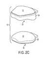
- FIG. 2Cis an exploded view of the prosthetic disc device of FIG. 2A ;
- FIG. 3is a perspective view of another embodiment of the prosthetic disc device
- FIG. 4Ais a perspective view of still another embodiment of the prosthetic disc device including a bone attachment element
- FIG. 4Bis a side view of the prosthetic disc device of FIG. 4A ;
- FIG. 5Ais a perspective view of a prosthetic disc device with another embodiment of the bone attachment element
- FIG. 5Bis a side view of the prosthetic disc device of FIG. 5A ;
- FIG. 6Ais a perspective view of another embodiment of the prosthetic disc device.
- FIG. 6Bis a side view of the prosthetic disc device of FIG. 6A ;
- FIG. 7Ais a perspective view of yet another embodiment of the prosthetic disc device.
- FIG. 7Bis a side view of the prosthetic disc device of FIG. 7A ;
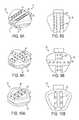
- FIG. 8Ais a view of the prosthetic disc device with a snap-on bone attachment element
- FIG. 8Bis a top view of the prosthetic disc device of FIG. 8A ;
- FIG. 9Ais a perspective view of the prosthetic disc device with a bone attachment element seated within a recess in a bone facing surface;
- FIG. 9Bis a top view of the prosthetic disc device of FIG. 9A ;
- FIG. 10Ais a perspective view of another embodiment of the prosthetic disc device having a bone attachment element seated within a recess of the bone facing surface;
- FIG. 10Bis a top view of the prosthetic disc device of FIG. 10A ;
- FIG. 11Ais a perspective view of another embodiment of a prosthetic disc device
- FIG. 11Bis a top view of the prosthetic disc device of FIG. 11A ;
- FIG. 11Cis a side view of the prosthetic disc device of FIG. 11A ;
- FIG. 12is a side view of a prosthetic disc device in the process of being inserted between vertebral bodies of a vertebral column;
- FIG. 13Ais a side view of the prosthetic disc device with the bone attachment element in the non-bone penetrating position
- FIG. 13Bis a perspective view of the prosthetic disc device of FIG. 13A ;
- FIG. 14is a side view of the prosthetic disc device of FIG. 13A with the bone attachment element in the bone penetrating position.
- the present inventionprovides a prosthesis that conserves vertebral function and provides wear resistant articulation surfaces.
- superior tribological wear propertiesare provided by forming at least a portion, and preferably all or substantially all, of the prosthesis from a ceramic material having sufficient strength to withstand in-vivo and insertion loading.
- Ceramic bearing surfacesprovide excellent wear resistant properties that allow the device to articulate when positioned within a patient's spine such that at least some of the natural mobility between adjacent vertebral bodies is conserved. Ceramic materials are also compatible with post-operative imaging such that a surgeon can determine if the prosthesis is properly positioned and/or can asses the health of surrounding tissue and adjacent levels.
- FIG. 1illustrates a perspective view of a portion of a vertebral column including vertebral bodies 1 a , 1 b , 1 c , 1 d , and natural discs 2 a and 2 b .
- a damaged disc between vertebral bodies 1 b and 1 chas been resected and replaced with a prosthetic disc 10 that has been inserted in the space created between the adjacent vertebral bodies ( 1 b , 1 c ).
- ceramic bearing surfaces of prosthesis 10allow vertebral bodies 1 b , 1 c to maintain at least some degree of mobility.
- disc 10can include bone mating surfaces, coatings, and/or bone penetrating elements, which together or separately, facilitate bone in-growth and help to fix the prosthesis in position.
- disc 10in one aspect, includes first and second endplates 24 , 26 each having an articulating contact surface 20 , 22 and a bone facing surface 16 , 18 where at least one of the first and second endplates is formed of a ceramic material. In one aspect, both endplates are formed entirely or substantially from ceramic materials.
- the prosthetic discis generally shaped and sized for positioning between adjacent vertebral bodies and contacting the vertebral bodies.
- disc 10can have a somewhat rectangular or trapezoidal shape with an anterior surface 14 and a posterior surface 12 , and a superior surface 16 and an inferior surface 18 .
- the superior 16 and inferior 18 surfacesare bone facing surfaces while interior surfaces 20 , 22 ( FIG. 2C ) are articulating surfaces.
- the sides of disc 10including anterior surface 14 and posterior surface 12 can be shaped to match the anatomical configuration of the inter-vertebral space into which disc 10 is inserted.
- posterior surface 12can have a width shorter than that of the anterior surface 14 , causing the width to taper from the posterior to the anterior.
- the corners of the prosthesiscan be rounded to reduce the chance of the prosthesis causing trauma to surrounding tissue.
- the height of disc 10is also adapted to be compatible with the anatomical structure of a vertebral column, and in particular, the height should be such that it provides the desired spacing between adjacent vertebrae.
- Disc 10in one aspect, is formed from a superior end plate 24 and an inferior endplate 26 , each having a bone facing surface 16 , 18 and an articulating contact surface 20 , 22 that allow the endplates to move relative to one another.
- FIG. 2Cshows an exploded view of disc 10 with articulating surface 22 of inferior endplate 26 adapted to articulate with articulating surface 20 of superior endplate 24 .
- Articulating surfaces 20 , 22can have a variety of shapes that allow movement of the adjacent vertebra to which they are attached.
- articulating surfaces 20 , 22are complementary, with articulating surface 22 having a convex configuration that is received within a concave articulating surface 20 .
- Articulating surfaces 20 , 22can be formed such that the movement of endplates 24 and 26 (and their respective vertebral bodies) is similar to the action of a natural vertebral disc.
- the shape of articulating surfaces 20 , 22allows for flexion, extension, lateral bending, and/or rotational movement.
- articulation of endplates 24 , 26could be provided by a three-piece (or more) design.
- a motile corecould be positioned between endplates 24 , 26 .
- Other exemplary designscould include a ball-in-trough configuration.
- endplates 24 , 26are configured such that relative movement is not limited or constrained by the structure of prosthetic disc 10 . As the endplates move relative to one another they do not encounter another portion of disc 10 that limits the amount of flexion, extension, lateral bending, or rotational movement of the endplates. Once implanted, only the anatomy of the vertebral column and surrounding tissue, or other implants, limit movement of the endplates relative to one another.
- Endplates 24 , 26can further include features for mating with an inserter tool (not shown).
- a mating element 30can extend from anterior surface 14 of at least one the endplates and be adapted for gripping by an inserter tool.
- mating element 30in one aspect, includes a male tab, having substantially flat upper and lower surfaces, that extends from the surface of each endplate 24 , 26 .
- an inserter toolcould mate with a female mating element 30 , including for example, a recess in the anterior surface 14 of disc 10 .
- mating element 30could be positioned on a side surface of prosthetic disc 10 .
- one or both of side surfaces 32 , 34 of prosthetic disc 10could include a slot within which an inserter tool could be seated.
- prosthetic disc 10does not include an element particularly adapted for mating with an inserter tool. Instead, an inserter tool adapted to grip the surfaces of disc 10 , such as, bone facing surfaces 16 , 18 ; sides 32 , 34 ; and/or anterior surface 14 . In one aspect, an insertion tool can instead have a shape corresponding to the anterior end of disc 10 and include features for gripping surfaces 16 , 18 .
- FIG. 3illustrates one embodiment of prosthetic disc 10 that includes area 35 on bone facing surfaces 16 , 18 that can be engaged by an inserter tool.
- inserter toolscan be adapted to mate with disc 10 .
- the superior and inferior surfaces 16 , 18 of prosthetic disc 10are positioned to face the adjacent vertebral bodies between which they will be inserted. When positioned within the vertebral column these surfaces face the exposed bone of the adjacent vertebral bodies. In one aspect, these bone facing surfaces 16 , 18 are bone contacting surfaces and are adapted to mate with bone. Once inserted within the vertebral column, the surfaces 16 , 18 contact the adjacent vertebral bodies and, over time, the disc is secured through osteointegration as bone grows into the ceramic material that forms the disc. Surfaces 16 , 18 can also include features, such as porous regions and/or recesses to enhance and facilitate bone in-growth.
- porous regions on the bone facing surfacesare provided by a coating 36 that fosters bone growth and/or bone adhesion.
- coating 36shown in FIG. 3 , could be positioned on surfaces 16 , 18 to provide a rough and/or porous structure into which bone can grow.
- coating 36could be formed from particles of ceramic material.
- Coating 36could include a variety of other materials such as binders (e.g., an adhesive) and/or biologically active materials that encourage bone in-growth. Exemplary materials include calcium phosphate, hydroxy apatite, plasma sprayed titanium beads, plasma sprayed CCM and combinations thereof.
- surfaces 16 , 18can also, or alternatively, include one or more bone attachment elements to help secure disc 10 to bone.
- Endplates 24 , 26can be formed from a variety of ceramic materials. Exemplary materials include alumina, zirconia, yttria, and blends thereof. One skilled in the art will appreciate that a variety of ceramic materials having low friction, wear resistant properties can be used to form endplates 24 , 26 . For example, ceramics such as Ceramtec's, Biolox® Delta material or Amedica's, MC 2 can be used.
- a non-ceramic bone attachment element 38 , 38 ′, 38 ′′, 38 ′′′, 38 ′′′′is positioned on one or both of the bone facing surfaces 16 , 18 .
- ceramic materialsare very hard and have low wear characteristics, forming bone penetrating members (e.g., spikes or teeth) from ceramic can be difficult because ceramic is brittle.
- bone attachment elements 38 , 38 ′, 38 ′′, 38 ′′′, 38 ′′′′can provide bone penetrating spikes or teeth 40 , 40 ′, 40 ′′ formed of a non-ceramic material.
- the spikes or teeth 40 , 40 ′, 40 ′′penetrate and/or engage bone to prevent disc 10 from moving out of position once implanted.
- non-ceramic bone attachment elementscan help to evenly distribute forces across the bone facing surfaces of the endplates.
- Bone attachment element 38 , 38 ′, 38 ′′, 38 ′′′, 38 ′′′′can be formed from a variety of non-ceramic materials such as metals and plastics.
- the bone attachment elementcould be formed from a strip of metal, such as stainless steel, titanium, or another biocompatible metal that is stamped or machined.
- the attachment elementcould be a rigid plastic such as, for example, carbon fiber reinforced plastics, polyetheretherketon, and/or other biocompatible plastics.
- bone attachment element 38 , 38 ′, 38 ′′, 38 ′′′, 38 ′′′′is formed from a material that is at least partially compatible with an imaging technique, such as magnetic resonance imaging (MRI).
- MRImagnetic resonance imaging
- the bone attachment elementis preferably small enough that it produces minimal interference with post-operative imaging.
- FIGS. 4A through 5Billustrate exemplary embodiments of bone attachment elements 38 positioned on bone facing surfaces 16 , 18 and having teeth adapted to penetrate bone.
- bone attachment elements 38comprise two parallel strips of material with raised portions defining teeth 40 .
- the bone attachment elementscan be positioned, for example, with their axes I i -I i and I 2 -I 2 oriented in the anterior/posterior direction. While two bone attachment elements are positioned on each surface 16 , 18 in FIGS. 4A through 5B , one skilled in the art will appreciate that disc 10 can include more than one bone attachment element per surface (e.g., three or more) or fewer (e.g., one).
- the bone attachment elementcould be positioned around the perimeter of the bone facing surfaces ( FIGS. 6A and 6B ), across the entire surface of the bone facing surfaces ( FIGS. 7A and 7B ), in a cross configuration ( FIGS. 9A and 9B ), around the perimeter and across the center of the bone facing surfaces ( FIGS. 10A and 10B ), and as connected parallel strips ( FIGS. 11A and 11B ).
- attachment elements 38 , 38 ′, 38 ′′, 38 ′′′, 38 ′′′′can cover less than the full area of bone facing surfaces 16 , 18 .
- a portion of the ceramic bone facing surfaces 16 , 18thus remain uncovered by bone attachment element 38 , 38 ′, 38 ′′, 38 ′′′, 38 ′′′′ and will accommodate bone in-growth.
- FIGS. 5A through 6B and 8 A through 14illustrate disc 10 with at least a portion of bone facing surfaces 16 , 18 uncovered by the bone attachment elements.
- the small profile of the bone attachment elementscan facilitate post-operative imaging. For example, where the bone attachment element is partially compatible with imaging techniques, covering only a portion of bone facing surfaces 16 , 18 with the bone attachment element can minimize interference with post-operative imaging.
- Bone attachment element 38 , 38 ′, 38 ′′, 38 ′′′, 38 ′′′′can be fixed to prosthetic device 10 in a variety of ways, including, for example, brazing, adhesion, mechanical attachment, and combinations thereof. Endplates 24 and 26 can also include features, such as a recess to assist with attachment of the bone attachment element.
- bone attachment element 38 ′is mated with disc prosthesis 10 by way of a mechanical interlock, such as, for example snap-fit, friction fit, tongue-and-groove, overmolding, overcasting, thermal interference fit, and combination thereof.
- a mechanical interlocksuch as, for example snap-fit, friction fit, tongue-and-groove, overmolding, overcasting, thermal interference fit, and combination thereof.
- the bone attachment elementcan mate or interlock with recesses 42 on the anterior and posterior surfaces 14 , 12 of disc 10 .
- the ends of bone attachment element 38 ′can be flexible and include a protrusion that snaps into recess 42 .
- bone attachment element 38 ′′is seated within a recess in the bone facing surfaces ( 16 , 18 ).
- the bone attachment elementcould be flush with the bone facing surfaces 16 , 18 , such that surfaces 16 , 18 are easily accessed by bone.
- FIGS. 9A through 10Balso illustrate embodiments in which bone attachment element 38 ′′ is seated with a recess in the surfaces 16 , 18 of the disc prosthesis.
- the bone attachment elementcan be mated within the recess in a variety of ways including, for example, mechanical interlock and adhesion.
- the bone attachment elementis formed within a recess.
- polymercan be poured into a recess (e.g., an overhanging recess) in the bone facing surfaces 16 , 18 of disc prosthesis 10 and then hardened to form bone attachment element 38 ′′.
- attachment element 38 ′′could be held on the bone facing surface(s) with an adhesive, such as, for example brazing, bone cement, and/or an epoxy.
- bone attachment element 38 ′′′rather than endplates 24 , 26 , includes features for mating with an inserter tool.
- FIGS. 11A through 11Cillustrate disc prosthesis 10 including mating element 30 ′ defined by extension portion 50 formed integrally with bone attachment element 38 ′′′. Instead of an inserter tool mating with the ceramic of the endplates 24 , 26 , the inserter tool can mate with the non-ceramic bone attachment element 38 ′′′.
- extension portion 50can have a “T” shape and extend from the anterior portion of the prosthetic disc. In one aspect, extension portions 50 are positioned on bone mating elements 38 ′′′.
- extension portion 50can have a built in fault that will fracture prior to the ceramic endplates breaking.
- extension portion 50can be constructed of materials that will give way prior to reaching a threshold force.
- Teeth 40positioned on bone attachment element 38 , 38 ′, 38 ′′, 38 ′′′, 38 ′′′′, can be positioned at an angle with respect to the bone facing surfaces 16 , 18 of disc 10 , such that the teeth are driven into bone by retropulsive forces acting on the disc.
- the angle of teeth 40 with respect to the bone facing surface of the endplatecan be in the range of about 5° and 75°, and preferably in the range of about 30° and 70°.
- teeth 40are formed from a ridged material and are fixedly positioned.
- Teeth 40can alternatively be flexible to facilitate insertion such that they are pushed down (i.e., retracted or flattened) during insertion. Once the disc is inserted, the teeth will press against the bone to resist retropulsion.
- teeth 40can have a size, shape, and orientation that will be effective to resist removal or migration of disc 10 .
- the teethare unidirectional and are inclined in the posterior-anterior direction. Teeth 40 will not grab bone as disc 10 is inserted, but will resist retropulsion once the disc is inserted.
- the teethcan be positioned at an angle with respect to the direction of insertion.
- teeth 40can be angled with respect to the axis L-L shown in FIG. 5A . This orientation helps to prevent lateral movement of the prosthetic disc.
- disc 10in another embodiment, includes rigid teeth 40 ′ which can extend in the superior/inferior direction. Teeth 40 ′ can penetrate bone to hold disc 10 in place after insertion.
- FIGS. 6A through 7Billustrate rigid teeth 40 ′ positioned on a single bone attachment element. Movement of the disc in any direction will be resisted by the engagement of the teeth into bone.
- bone attachment element 38 ′′′′is formed from a shape memory material.
- the bone attachment elementcan move from a non-bone penetrating configuration to a bone penetrating configuration.
- the shape memory materialis heat activated and once inserted into a vertebral column, heat (e.g., body heat and/or a supplemental heat source) activates the shape memory material.
- heate.g., body heat and/or a supplemental heat source
- bone penetrating teeth 40 ′′ on bone attachment element 38 ′′′′move from a lowered position to an active, raised position.
- FIG. 12illustrates a vertebral column with disc tissue removed and disc prosthesis 10 ready for insertion.
- teeth 40 ′′are oriented in a low profile non-bone penetrating position.
- FIGS. 13A and 13Bfurther illustrate disc 10 with teeth 40 ′′, formed of a shape memory material, in the non-bone engaging position.
- Disc 10can be inserted with teeth 40 ′′ in their non-bone engaging position to facilitate insertion by reducing interference between teeth 40 ′′ and bone.
- bone attachment element 38 ′′′′is activated by an activating force, such as body heat and/or a supplemental heat source, and teeth 40 ′′ become oriented in a bone engaging position as shown in FIG. 14A .
- Bone attachment element 38 ′′′′can be formed from the variety of shape memory materials.
- Exemplary materialsinclude, for example, nickel-titanium intermetallic compounds (e.g., Nitinol) that exhibit thermal shape memory.
- Preferred materialsinclude those that are activated at a temperature above room temperature, such as at, or slightly below, body temperature.
- spike profilesare cut into a sheet of Nitinol and the sheet is heat treated so that the spikes will deploy (i.e., assume a bone penetrating position) at body temperature.
- Spikes 40 ′′can lie substantially in the same plane as bone attachment elements 38 ′′′′ during implantations, then deploy into a raised, bone penetrating position once the disc is inserted.
- the bone attachment elementscan be in the form of bone engaging hooks (not shown), which can also be formed from a shape memory material.
- the bone engaging elementscan include wires when in the non-activated, non-bone penetrating condition. In the activated condition, for example, the wires may lie substantially in the same plane as surfaces 16 , 18 . Upon activation by an activating force, the wires are transformed into hooks that penetrate and/or securely engage bone.
Landscapes
- Health & Medical Sciences (AREA)
- Engineering & Computer Science (AREA)
- Biomedical Technology (AREA)
- Neurology (AREA)
- Orthopedic Medicine & Surgery (AREA)
- Cardiology (AREA)
- Oral & Maxillofacial Surgery (AREA)
- Transplantation (AREA)
- Heart & Thoracic Surgery (AREA)
- Vascular Medicine (AREA)
- Life Sciences & Earth Sciences (AREA)
- Animal Behavior & Ethology (AREA)
- General Health & Medical Sciences (AREA)
- Public Health (AREA)
- Veterinary Medicine (AREA)
- Prostheses (AREA)
- Materials For Medical Uses (AREA)
Abstract
Description
Claims (16)
Priority Applications (6)
| Application Number | Priority Date | Filing Date | Title |
|---|---|---|---|
| US10/908,766US8021428B2 (en) | 2004-06-30 | 2005-05-25 | Ceramic disc prosthesis |
| JP2007519221AJP2008504870A (en) | 2004-06-30 | 2005-05-26 | Ceramic intervertebral disc prosthesis |
| AU2005262716AAU2005262716A1 (en) | 2004-06-30 | 2005-05-26 | Ceramic disc prosthesis |
| PCT/US2005/018457WO2006007195A2 (en) | 2004-06-30 | 2005-05-26 | Ceramic disc prosthesis |
| CA002571481ACA2571481A1 (en) | 2004-06-30 | 2005-05-26 | Ceramic disc prosthesis |
| EP05753819AEP1761214B1 (en) | 2004-06-30 | 2005-05-26 | Ceramic disc prosthesis |
Applications Claiming Priority (2)
| Application Number | Priority Date | Filing Date | Title |
|---|---|---|---|
| US58405404P | 2004-06-30 | 2004-06-30 | |
| US10/908,766US8021428B2 (en) | 2004-06-30 | 2005-05-25 | Ceramic disc prosthesis |
Publications (2)
| Publication Number | Publication Date |
|---|---|
| US20060004453A1 US20060004453A1 (en) | 2006-01-05 |
| US8021428B2true US8021428B2 (en) | 2011-09-20 |
Family
ID=35515047
Family Applications (1)
| Application Number | Title | Priority Date | Filing Date |
|---|---|---|---|
| US10/908,766Expired - Fee RelatedUS8021428B2 (en) | 2004-06-30 | 2005-05-25 | Ceramic disc prosthesis |
Country Status (6)
| Country | Link |
|---|---|
| US (1) | US8021428B2 (en) |
| EP (1) | EP1761214B1 (en) |
| JP (1) | JP2008504870A (en) |
| AU (1) | AU2005262716A1 (en) |
| CA (1) | CA2571481A1 (en) |
| WO (1) | WO2006007195A2 (en) |
Cited By (5)
| Publication number | Priority date | Publication date | Assignee | Title |
|---|---|---|---|---|
| US20110218630A1 (en)* | 2008-07-03 | 2011-09-08 | Christine Niess | Intervertebral disc endoprosthesis |
| US9408714B1 (en) | 2015-06-12 | 2016-08-09 | Amendia, Inc. | Artificial disc |
| US9693876B1 (en) | 2012-03-30 | 2017-07-04 | Ali H. MESIWALA | Spinal fusion implant and related methods |
| US11033409B2 (en) | 2015-09-24 | 2021-06-15 | Otto Bock Healthcare Products Gmbh | Prosthesis device |
| US11452618B2 (en) | 2019-09-23 | 2022-09-27 | Dimicron, Inc | Spinal artificial disc removal tool |
Families Citing this family (170)
| Publication number | Priority date | Publication date | Assignee | Title |
|---|---|---|---|---|
| US7494507B2 (en)* | 2000-01-30 | 2009-02-24 | Diamicron, Inc. | Articulating diamond-surfaced spinal implants |
| US8388684B2 (en) | 2002-05-23 | 2013-03-05 | Pioneer Signal Technology, Inc. | Artificial disc device |
| US7001433B2 (en)* | 2002-05-23 | 2006-02-21 | Pioneer Laboratories, Inc. | Artificial intervertebral disc device |
| AU2003226586A1 (en) | 2002-09-19 | 2004-04-08 | Malan De Villiers | Intervertebral prosthesis |
| ZA200506029B (en)* | 2003-01-31 | 2006-10-25 | Spinalmotion Inc | Spinal Midline Indicator |
| WO2004066884A1 (en)* | 2003-01-31 | 2004-08-12 | Spinalmotion, Inc. | Intervertebral prosthesis placement instrument |
| US7575599B2 (en)* | 2004-07-30 | 2009-08-18 | Spinalmotion, Inc. | Intervertebral prosthetic disc with metallic core |
| US20090076614A1 (en)* | 2007-09-17 | 2009-03-19 | Spinalmotion, Inc. | Intervertebral Prosthetic Disc with Shock Absorption Core |
| US7442211B2 (en)* | 2003-05-27 | 2008-10-28 | Spinalmotion, Inc. | Intervertebral prosthetic disc |
| US10052211B2 (en) | 2003-05-27 | 2018-08-21 | Simplify Medical Pty Ltd. | Prosthetic disc for intervertebral insertion |
| FR2858546B1 (en)* | 2003-08-04 | 2006-04-28 | Spine Next Sa | INTERVERTEBRAL DISC PROSTHESIS |
| US7585326B2 (en) | 2004-08-06 | 2009-09-08 | Spinalmotion, Inc. | Methods and apparatus for intervertebral disc prosthesis insertion |
| WO2006058221A2 (en) | 2004-11-24 | 2006-06-01 | Abdou Samy M | Devices and methods for inter-vertebral orthopedic device placement |
| US8083797B2 (en)* | 2005-02-04 | 2011-12-27 | Spinalmotion, Inc. | Intervertebral prosthetic disc with shock absorption |
| US9345587B2 (en)* | 2006-03-22 | 2016-05-24 | Beacon Biomedical, Llc | Pivotal lateral cage and method of insertion |
| WO2007121320A2 (en)* | 2006-04-12 | 2007-10-25 | Spinalmotion, Inc. | Posterior spinal device and method |
| US8715350B2 (en)* | 2006-09-15 | 2014-05-06 | Pioneer Surgical Technology, Inc. | Systems and methods for securing an implant in intervertebral space |
| US8377133B2 (en)* | 2006-09-15 | 2013-02-19 | Pioneer Surgical Technology, Inc. | Systems and methods for sizing, inserting and securing an implant in intervertebral space |
| WO2008034135A2 (en) | 2006-09-15 | 2008-03-20 | Pioneer Surgical Technology, Inc. | Joint arthroplasty devices having articulating members |
| WO2008034140A2 (en)* | 2006-09-15 | 2008-03-20 | Pioneer Surgical Technology, Inc. | Systems and methods for sizing, inserting and securing an implant intervertebral space |
| US20080140204A1 (en)* | 2006-12-07 | 2008-06-12 | Warsaw Orthopedic, Inc. | Vertebral Implant Systems and Methods of Use |
| US7892285B2 (en)* | 2007-01-02 | 2011-02-22 | Zimmer Spine, Inc. | Universal joint total disc replacement |
| WO2008098228A2 (en) | 2007-02-09 | 2008-08-14 | Diamicron, Inc. | Multi-lobe artificial spine joint |
| US9358121B2 (en)* | 2007-03-10 | 2016-06-07 | Spinesmith Partners, L.P. | Artificial disc with unique articulating geometry and associated methods |
| US9289310B2 (en) | 2007-03-10 | 2016-03-22 | Spinesmith Partners, L.P. | Artificial disc with post and modular collar |
| US10335288B2 (en)* | 2007-03-10 | 2019-07-02 | Spinesmith Partners, L.P. | Surgical implant secured by pegs and associated methods |
| US20090043391A1 (en) | 2007-08-09 | 2009-02-12 | Spinalmotion, Inc. | Customized Intervertebral Prosthetic Disc with Shock Absorption |
| US8328818B1 (en) | 2007-08-31 | 2012-12-11 | Globus Medical, Inc. | Devices and methods for treating bone |
| US8231676B2 (en)* | 2007-09-17 | 2012-07-31 | Pioneer Surgical Technology, Inc. | Motion preserving artificial intervertebral disc device |
| US20090105834A1 (en) | 2007-10-22 | 2009-04-23 | Spinalmotion, Inc. | Dynamic Spacer Device and Method for Spanning a Space Formed upon Removal of an Intervertebral Disc |
| WO2009094477A1 (en)* | 2008-01-25 | 2009-07-30 | Spinalmotion, Inc. | Compliant implantable prosthetic joint with preloaded spring |
| US8764833B2 (en) | 2008-03-11 | 2014-07-01 | Spinalmotion, Inc. | Artificial intervertebral disc with lower height |
| US9034038B2 (en)* | 2008-04-11 | 2015-05-19 | Spinalmotion, Inc. | Motion limiting insert for an artificial intervertebral disc |
| EP2278941A1 (en)* | 2008-05-05 | 2011-02-02 | Spinalmotion Inc. | Polyaryletherketone artificial intervertebral disc |
| US9220603B2 (en)* | 2008-07-02 | 2015-12-29 | Simplify Medical, Inc. | Limited motion prosthetic intervertebral disc |
| EP2299944A4 (en) | 2008-07-17 | 2013-07-31 | Spinalmotion Inc | SYSTEM FOR INSTALLING ARTIFICIAL INTERVERTEBRAL DISCS |
| EP2299941A1 (en) | 2008-07-18 | 2011-03-30 | Spinalmotion Inc. | Posterior prosthetic intervertebral disc |
| JP5602739B2 (en) | 2008-09-02 | 2014-10-08 | ジンテス ゲゼルシャフト ミット ベシュレンクテル ハフツング | Intervertebral implant having blades for connection to adjacent vertebral bodies |
| US8147554B2 (en) | 2008-10-13 | 2012-04-03 | Globus Medical, Inc. | Intervertebral spacer |
| US8545566B2 (en) | 2008-10-13 | 2013-10-01 | Globus Medical, Inc. | Articulating spacer |
| US8349015B2 (en)* | 2009-02-11 | 2013-01-08 | Howmedica Osteonics Corp. | Intervertebral implant with integrated fixation |
| EP2835113B1 (en) | 2009-08-10 | 2016-05-25 | Howmedica Osteonics Corp. | Intervertebral implant with integrated fixation |
| US8709086B2 (en) | 2009-10-15 | 2014-04-29 | Globus Medical, Inc. | Expandable fusion device and method of installation thereof |
| US8062375B2 (en) | 2009-10-15 | 2011-11-22 | Globus Medical, Inc. | Expandable fusion device and method of installation thereof |
| US10806596B2 (en) | 2009-10-15 | 2020-10-20 | Globus Medical, Inc. | Expandable fusion device and method installation thereof |
| US10327917B2 (en) | 2009-10-15 | 2019-06-25 | Globus Medical, Inc. | Expandable fusion device and method of installation thereof |
| US8556979B2 (en) | 2009-10-15 | 2013-10-15 | Globus Medical, Inc. | Expandable fusion device and method of installation thereof |
| US11344430B2 (en) | 2009-10-15 | 2022-05-31 | Globus Medical, Inc. | Expandable fusion device and method of installation thereof |
| US11564807B2 (en) | 2009-10-15 | 2023-01-31 | Globus Medical, Inc. | Expandable fusion device and method of installation thereof |
| US11103366B2 (en) | 2009-10-15 | 2021-08-31 | Globus Medical, Inc. | Expandable fusion device and method of installation thereof |
| US8685098B2 (en) | 2010-06-25 | 2014-04-01 | Globus Medical, Inc. | Expandable fusion device and method of installation thereof |
| US9155628B2 (en) | 2009-10-15 | 2015-10-13 | Globus Medical, Inc. | Expandable fusion device and method of installation thereof |
| US9216095B2 (en) | 2009-10-15 | 2015-12-22 | Globus Medical, Inc. | Expandable fusion device and method of installation thereof |
| US10098758B2 (en) | 2009-10-15 | 2018-10-16 | Globus Medical, Inc. | Expandable fusion device and method of installation thereof |
| US8679183B2 (en) | 2010-06-25 | 2014-03-25 | Globus Medical | Expandable fusion device and method of installation thereof |
| EP2496187B1 (en) | 2009-11-03 | 2016-12-21 | Howmedica Osteonics Corp. | Intervertebral implant with integrated fixation |
| US8764806B2 (en) | 2009-12-07 | 2014-07-01 | Samy Abdou | Devices and methods for minimally invasive spinal stabilization and instrumentation |
| US9480511B2 (en) | 2009-12-17 | 2016-11-01 | Engage Medical Holdings, Llc | Blade fixation for ankle fusion and arthroplasty |
| US8353963B2 (en) | 2010-01-12 | 2013-01-15 | Globus Medical | Expandable spacer and method for use thereof |
| US9913726B2 (en) | 2010-02-24 | 2018-03-13 | Globus Medical, Inc. | Expandable intervertebral spacer and method of posterior insertion thereof |
| US8870880B2 (en) | 2010-04-12 | 2014-10-28 | Globus Medical, Inc. | Angling inserter tool for expandable vertebral implant |
| US9301850B2 (en) | 2010-04-12 | 2016-04-05 | Globus Medical, Inc. | Expandable vertebral implant |
| US9597200B2 (en) | 2010-06-25 | 2017-03-21 | Globus Medical, Inc | Expandable fusion device and method of installation thereof |
| US9474625B2 (en) | 2010-09-03 | 2016-10-25 | Globus Medical, Inc | Expandable fusion device and method of installation thereof |
| US8491659B2 (en) | 2010-09-03 | 2013-07-23 | Globus Medical, Inc. | Expandable fusion device and method of installation thereof |
| US8852279B2 (en) | 2010-09-03 | 2014-10-07 | Globus Medical, Inc. | Expandable fusion device and method of installation thereof |
| US10779957B2 (en) | 2010-09-03 | 2020-09-22 | Globus Medical, Inc. | Expandable fusion device and method of installation thereof |
| US10869768B2 (en) | 2010-09-03 | 2020-12-22 | Globus Medical Inc. | Expandable fusion device and method of installation thereof |
| US11446162B2 (en) | 2010-09-03 | 2022-09-20 | Globus Medical, Inc. | Expandable fusion device and method of installation thereof |
| US10709573B2 (en) | 2010-09-03 | 2020-07-14 | Globus Medical Inc. | Expandable fusion device and method of installation thereof |
| US9566168B2 (en) | 2010-09-03 | 2017-02-14 | Globus Medical, Inc. | Expandable fusion device and method of installation thereof |
| US8632595B2 (en) | 2010-09-03 | 2014-01-21 | Globus Medical, Inc. | Expandable fusion device and method of installation thereof |
| US10835387B2 (en) | 2010-09-03 | 2020-11-17 | Globus Medical Inc. | Expandable fusion device and method of installation thereof |
| US8845731B2 (en) | 2010-09-03 | 2014-09-30 | Globus Medical, Inc. | Expandable fusion device and method of installation thereof |
| US8845734B2 (en) | 2010-09-03 | 2014-09-30 | Globus Medical, Inc. | Expandable fusion device and method of installation thereof |
| US11793654B2 (en) | 2010-09-03 | 2023-10-24 | Globus Medical, Inc. | Expandable fusion device and method of installation thereof |
| US8845732B2 (en) | 2010-09-03 | 2014-09-30 | Globus Medical, Inc. | Expandable fusion device and method of installation thereof |
| US10842644B2 (en) | 2010-09-03 | 2020-11-24 | Globus Medical, Inc. | Expandable fusion device and method of installation thereof |
| US10945858B2 (en) | 2010-09-03 | 2021-03-16 | Globus Medical, Inc. | Expandable interspinous process fixation device |
| US10758367B2 (en) | 2010-09-03 | 2020-09-01 | Globus Medical Inc. | Expandable fusion device and method of installation thereof |
| US10512550B2 (en) | 2010-09-03 | 2019-12-24 | Globus Medical, Inc. | Expandable interspinous process fixation device |
| US8435298B2 (en) | 2010-09-03 | 2013-05-07 | Globus Medical, Inc. | Expandable fusion device and method of installation thereof |
| US9351848B2 (en) | 2010-09-03 | 2016-05-31 | Globus Medical, Inc. | Expandable fusion device and method of installation thereof |
| US12059358B2 (en) | 2010-09-03 | 2024-08-13 | Globus Medical Inc. | Expandable fusion device and method of installation thereof |
| US12370057B2 (en) | 2010-09-03 | 2025-07-29 | Globus Medical, Inc. | Expandable fusion device and method of installation thereof |
| US9907673B2 (en) | 2010-09-03 | 2018-03-06 | Globus Medical, Inc. | Expandable fusion device and method of installation thereof |
| US10085849B2 (en) | 2010-09-03 | 2018-10-02 | Globus Medical, Inc. | Expandable fusion device and method of installation thereof |
| US9855151B2 (en) | 2010-09-03 | 2018-01-02 | Globus Medical, Inc | Expandable fusion device and method of installation thereof |
| US20120109306A1 (en)* | 2010-10-28 | 2012-05-03 | Warsaw Orthopedic, Inc. | Spinal implant |
| EP2651341B1 (en) | 2010-12-16 | 2017-01-04 | Engage Medical Holdings, LLC | Arthroplasty systems and methods |
| US8845728B1 (en) | 2011-09-23 | 2014-09-30 | Samy Abdou | Spinal fixation devices and methods of use |
| US8864833B2 (en) | 2011-09-30 | 2014-10-21 | Globus Medical, Inc. | Expandable fusion device and method of installation thereof |
| US9254130B2 (en) | 2011-11-01 | 2016-02-09 | Hyun Bae | Blade anchor systems for bone fusion |
| US9615856B2 (en) | 2011-11-01 | 2017-04-11 | Imds Llc | Sacroiliac fusion cage |
| US9198769B2 (en) | 2011-12-23 | 2015-12-01 | Pioneer Surgical Technology, Inc. | Bone anchor assembly, bone plate system, and method |
| US20130226240A1 (en) | 2012-02-22 | 2013-08-29 | Samy Abdou | Spinous process fixation devices and methods of use |
| US10238382B2 (en) | 2012-03-26 | 2019-03-26 | Engage Medical Holdings, Llc | Blade anchor for foot and ankle |
| US9044342B2 (en) | 2012-05-30 | 2015-06-02 | Globus Medical, Inc. | Expandable interbody spacer |
| US9198767B2 (en) | 2012-08-28 | 2015-12-01 | Samy Abdou | Devices and methods for spinal stabilization and instrumentation |
| EP2716261A1 (en)* | 2012-10-02 | 2014-04-09 | Titan Spine, LLC | Implants with self-deploying anchors |
| US9107763B2 (en) | 2012-10-04 | 2015-08-18 | DePuy Synthes Products, Inc. | Articulating intervertebral implant |
| US9320617B2 (en) | 2012-10-22 | 2016-04-26 | Cogent Spine, LLC | Devices and methods for spinal stabilization and instrumentation |
| US10350081B2 (en) | 2012-12-11 | 2019-07-16 | Globus Medical, Inc. | Expandable vertebral implant |
| US10299934B2 (en) | 2012-12-11 | 2019-05-28 | Globus Medical, Inc | Expandable vertebral implant |
| US9011493B2 (en) | 2012-12-31 | 2015-04-21 | Globus Medical, Inc. | Spinous process fixation system and methods thereof |
| US9782265B2 (en) | 2013-02-15 | 2017-10-10 | Globus Medical, Inc | Articulating and expandable vertebral implant |
| US10117754B2 (en) | 2013-02-25 | 2018-11-06 | Globus Medical, Inc. | Expandable intervertebral implant |
| US9204972B2 (en) | 2013-03-01 | 2015-12-08 | Globus Medical, Inc. | Articulating expandable intervertebral implant |
| US9770343B2 (en) | 2013-03-01 | 2017-09-26 | Globus Medical Inc. | Articulating expandable intervertebral implant |
| US9554918B2 (en) | 2013-03-01 | 2017-01-31 | Globus Medical, Inc. | Articulating expandable intervertebral implant |
| US9198772B2 (en) | 2013-03-01 | 2015-12-01 | Globus Medical, Inc. | Articulating expandable intervertebral implant |
| US10004607B2 (en) | 2013-03-01 | 2018-06-26 | Globus Medical, Inc. | Articulating expandable intervertebral implant |
| US9186258B2 (en) | 2013-03-15 | 2015-11-17 | Globus Medical, Inc. | Expandable intervertebral implant |
| US9456906B2 (en) | 2013-03-15 | 2016-10-04 | Globus Medical, Inc. | Expandable intervertebral implant |
| US9572677B2 (en) | 2013-03-15 | 2017-02-21 | Globus Medical, Inc. | Expandable intervertebral implant |
| US9233009B2 (en) | 2013-03-15 | 2016-01-12 | Globus Medical, Inc. | Expandable intervertebral implant |
| US9149367B2 (en) | 2013-03-15 | 2015-10-06 | Globus Medical Inc | Expandable intervertebral implant |
| US9839528B2 (en) | 2014-02-07 | 2017-12-12 | Globus Medical, Inc. | Variable lordosis spacer and related methods of use |
| US9402739B2 (en) | 2014-02-07 | 2016-08-02 | Globus Medical, Inc. | Variable lordosis spacer and related methods of use |
| US9662224B2 (en) | 2014-02-07 | 2017-05-30 | Globus Medical, Inc. | Variable lordosis spacer and related methods of use |
| US9901459B2 (en) | 2014-12-16 | 2018-02-27 | Globus Medical, Inc. | Expandable fusion devices and methods of installation thereof |
| AU2016200179B2 (en) | 2015-01-14 | 2020-09-17 | Stryker European Operations Holdings Llc | Spinal implant with porous and solid surfaces |
| AU2016200195B2 (en) | 2015-01-14 | 2020-07-02 | Vb Spine Us Opco Llc | Spinal implant with fluid delivery capabilities |
| US9814602B2 (en) | 2015-05-14 | 2017-11-14 | Globus Medical, Inc. | Expandable intervertebral implants and methods of installation thereof |
| CA2930123A1 (en) | 2015-05-18 | 2016-11-18 | Stryker European Holdings I, Llc | Partially resorbable implants and methods |
| US10631997B2 (en) | 2015-05-21 | 2020-04-28 | Globus Medical, Inc. | Device and method for deployment of an anchoring device for intervertebral spinal fusion |
| US10765532B2 (en) | 2015-05-21 | 2020-09-08 | Globus Medical, Inc. | Device and method for deployment of an anchoring device for intervertebral spinal fusion |
| US10433975B2 (en) | 2015-05-21 | 2019-10-08 | Globus Medical, Inc. | Device and method for deployment of an anchoring device for intervertebral spinal fusion |
| US9848996B2 (en) | 2015-06-17 | 2017-12-26 | Globus Medical, Inc. | Variable lordotic interbody spacer |
| US11045326B2 (en) | 2015-07-17 | 2021-06-29 | Global Medical Inc | Intervertebral spacer and plate |
| US10016282B2 (en) | 2015-07-17 | 2018-07-10 | Globus Medical, Inc. | Intervertebral spacer and plate |
| US10137009B2 (en) | 2015-09-02 | 2018-11-27 | Globus Medical, Inc. | Expandable intervertebral fusion devices and methods of installation thereof |
| US10034768B2 (en) | 2015-09-02 | 2018-07-31 | Globus Medical, Inc. | Implantable systems, devices and related methods |
| US10857003B1 (en) | 2015-10-14 | 2020-12-08 | Samy Abdou | Devices and methods for vertebral stabilization |
| US10219914B2 (en) | 2015-11-10 | 2019-03-05 | Globus Medical, Inc. | Stabilized expandable intervertebral spacer |
| US10524928B2 (en) | 2015-12-15 | 2020-01-07 | Globus Medical, Inc | Stabilized intervertebral spacer |
| US10369004B2 (en) | 2015-12-16 | 2019-08-06 | Globus Medical, Inc. | Expandable intervertebralspacer |
| US9974575B2 (en) | 2016-02-02 | 2018-05-22 | Globus Medical, Inc. | Expandable spinal fixation system |
| US9974662B2 (en) | 2016-06-29 | 2018-05-22 | Globus Medical, Inc. | Expandable fusion device and method of installation thereof |
| US10052215B2 (en) | 2016-06-29 | 2018-08-21 | Globus Medical, Inc. | Expandable fusion device and method of installation thereof |
| US12161563B2 (en) | 2016-09-14 | 2024-12-10 | Globus Medical, Inc. | Systems and methods for expandable corpectomy spacer implantation |
| US11596526B2 (en) | 2016-09-14 | 2023-03-07 | Globus Medical Inc. | Systems and methods for expandable corpectomy spacer implantation |
| US10390955B2 (en) | 2016-09-22 | 2019-08-27 | Engage Medical Holdings, Llc | Bone implants |
| US10744000B1 (en) | 2016-10-25 | 2020-08-18 | Samy Abdou | Devices and methods for vertebral bone realignment |
| US10973648B1 (en) | 2016-10-25 | 2021-04-13 | Samy Abdou | Devices and methods for vertebral bone realignment |
| US10456272B2 (en) | 2017-03-03 | 2019-10-29 | Engage Uni Llc | Unicompartmental knee arthroplasty |
| US11540928B2 (en) | 2017-03-03 | 2023-01-03 | Engage Uni Llc | Unicompartmental knee arthroplasty |
| WO2019051260A1 (en) | 2017-09-08 | 2019-03-14 | Pioneer Surgical Technology, Inc. | Intervertebral implants, instruments, and methods |
| EP3459502B1 (en) | 2017-09-20 | 2024-05-22 | Stryker European Operations Holdings LLC | Spinal implants |
| USD907771S1 (en) | 2017-10-09 | 2021-01-12 | Pioneer Surgical Technology, Inc. | Intervertebral implant |
| US10709569B2 (en) | 2017-11-09 | 2020-07-14 | Globus Medical, Inc. | Expandable intervertebral implant |
| US10973658B2 (en) | 2017-11-27 | 2021-04-13 | Titan Spine, Inc. | Rotating implant and associated instrumentation |
| US11135070B2 (en) | 2018-02-14 | 2021-10-05 | Titan Spine, Inc. | Modular adjustable corpectomy cage |
| US11179248B2 (en) | 2018-10-02 | 2021-11-23 | Samy Abdou | Devices and methods for spinal implantation |
| US11179242B2 (en) | 2019-07-18 | 2021-11-23 | Globus Medical, Inc. | Expanding intervertebral implants |
| US11259933B2 (en) | 2019-09-06 | 2022-03-01 | Globus Medical Inc. | Expandable motion preservation spacer |
| US11337824B2 (en) | 2019-12-20 | 2022-05-24 | Globus Medical, Inc. | Stabilizing vertebrae with articulating implants |
| US11154405B2 (en) | 2020-01-23 | 2021-10-26 | Globus Medical, Inc. | Articulating expandable interbody fusions devices |
| US11191650B2 (en) | 2020-02-03 | 2021-12-07 | Globus Medical Inc. | Expandable fusions devices, instruments, and methods thereof |
| US11298240B2 (en) | 2020-06-16 | 2022-04-12 | Globus Medical, Inc. | Expanding intervertebral implants |
| US11357640B2 (en) | 2020-07-08 | 2022-06-14 | Globus Medical Inc. | Expandable interbody fusions devices |
| US20220117749A1 (en) | 2020-07-09 | 2022-04-21 | Globus Medical, Inc. | Intradiscal fixation systems |
| US11491020B2 (en) | 2020-07-09 | 2022-11-08 | Globus Medical, Inc. | Articulating and expandable interbody fusions devices |
| US11712346B2 (en) | 2021-12-02 | 2023-08-01 | Globus Medical, Inc. | Expandable fusion device with integrated deployable retention spikes |
| US12324748B2 (en) | 2021-12-02 | 2025-06-10 | Globus Medical, Inc. | Expandable fusion device with integrated deployable retention spikes |
| US12011364B2 (en) | 2022-06-15 | 2024-06-18 | Globus Medical, Inc | Expandable footprint implant |
| US11883080B1 (en) | 2022-07-13 | 2024-01-30 | Globus Medical, Inc | Reverse dynamization implants |
| US12396867B2 (en) | 2023-03-21 | 2025-08-26 | Globus Medical, Inc. | Expandable footprint implant |
| US12427038B2 (en) | 2023-06-27 | 2025-09-30 | Globus Medical Inc. | Expandable intervertebral interbody implants |
| US12396866B2 (en) | 2023-09-27 | 2025-08-26 | Globus Medical, Inc. | Expandable anterior lumbar implants |
Citations (87)
| Publication number | Priority date | Publication date | Assignee | Title |
|---|---|---|---|---|
| US4743260A (en) | 1985-06-10 | 1988-05-10 | Burton Charles V | Method for a flexible stabilization system for a vertebral column |
| JPS63164948A (en) | 1986-12-26 | 1988-07-08 | 京セラ株式会社 | Artificial disc for cervical spine |
| US5037438A (en) | 1989-07-25 | 1991-08-06 | Richards Medical Company | Zirconium oxide coated prosthesis for wear and corrosion resistance |
| US5092866A (en) | 1989-02-03 | 1992-03-03 | Breard Francis H | Flexible inter-vertebral stabilizer as well as process and apparatus for determining or verifying its tension before installation on the spinal column |
| US5258031A (en) | 1992-01-06 | 1993-11-02 | Danek Medical | Intervertebral disk arthroplasty |
| US5387213A (en) | 1991-02-05 | 1995-02-07 | Safir S.A.R.L. | Osseous surgical implant particularly for an intervertebral stabilizer |
| US5415661A (en) | 1993-03-24 | 1995-05-16 | University Of Miami | Implantable spinal assist device |
| US5425773A (en) | 1992-01-06 | 1995-06-20 | Danek Medical, Inc. | Intervertebral disk arthroplasty device |
| EP0669109A1 (en) | 1994-02-28 | 1995-08-30 | SULZER Medizinaltechnik AG | Stabilizer for adjacent vertebrae |
| US5474086A (en) | 1992-07-07 | 1995-12-12 | Chattanooga Group, Inc. | Apparatus for monitoring the motion of the lumbar spine |
| US5534029A (en) | 1992-12-14 | 1996-07-09 | Yumiko Shima | Articulated vertebral body spacer |
| US5540688A (en) | 1991-05-30 | 1996-07-30 | Societe "Psi" | Intervertebral stabilization device incorporating dampers |
| US5556431A (en) | 1992-03-13 | 1996-09-17 | B+E,Uml U+Ee Ttner-Janz; Karin | Intervertebral disc endoprosthesis |
| US5562737A (en) | 1993-11-18 | 1996-10-08 | Henry Graf | Extra-discal intervertebral prosthesis |
| US5571191A (en) | 1995-03-16 | 1996-11-05 | Fitz; William R. | Artificial facet joint |
| RU2080841C1 (en) | 1993-06-28 | 1997-06-10 | Частное предприятие "Алекс" | Intervertebral disk endoprosthesis |
| US5672175A (en) | 1993-08-27 | 1997-09-30 | Martin; Jean Raymond | Dynamic implanted spinal orthosis and operative procedure for fitting |
| US5676701A (en) | 1993-01-14 | 1997-10-14 | Smith & Nephew, Inc. | Low wear artificial spinal disc |
| US5895428A (en) | 1996-11-01 | 1999-04-20 | Berry; Don | Load bearing spinal joint implant |
| US5899941A (en) | 1997-12-09 | 1999-05-04 | Chubu Bearing Kabushiki Kaisha | Artificial intervertebral disk |
| USRE36221E (en) | 1989-02-03 | 1999-06-01 | Breard; Francis Henri | Flexible inter-vertebral stabilizer as well as process and apparatus for determining or verifying its tension before installation on the spinal column |
| US5961516A (en) | 1996-08-01 | 1999-10-05 | Graf; Henry | Device for mechanically connecting and assisting vertebrae with respect to one another |
| US6039763A (en) | 1998-10-27 | 2000-03-21 | Disc Replacement Technologies, Inc. | Articulating spinal disc prosthesis |
| US6063121A (en)* | 1998-07-29 | 2000-05-16 | Xavier; Ravi | Vertebral body prosthesis |
| US6132464A (en) | 1994-06-24 | 2000-10-17 | Paulette Fairant | Vertebral joint facets prostheses |
| US6146421A (en) | 1997-08-04 | 2000-11-14 | Gordon, Maya, Roberts And Thomas, Number 1, Llc | Multiple axis intervertebral prosthesis |
| US6228118B1 (en) | 1997-08-04 | 2001-05-08 | Gordon, Maya, Roberts And Thomas, Number 1, Llc | Multiple axis intervertebral prosthesis |
| WO2001045576A1 (en) | 1999-12-20 | 2001-06-28 | Synthes Ag Chur | Device for the stabilisation of two adjacent verterbral bodies of the spine |
| US6267764B1 (en) | 1996-11-15 | 2001-07-31 | Stryker France S.A. | Osteosynthesis system with elastic deformation for spinal column |
| US6273888B1 (en) | 1999-05-28 | 2001-08-14 | Sdgi Holdings, Inc. | Device and method for selectively preventing the locking of a shape-memory alloy coupling system |
| WO2002017803A2 (en) | 2000-09-01 | 2002-03-07 | Hôpital Sainte-Justine | Mobile dynamic system for treating spinal disorder |
| US6368350B1 (en) | 1999-03-11 | 2002-04-09 | Sulzer Spine-Tech Inc. | Intervertebral disc prosthesis and method |
| US20020065557A1 (en) | 2000-11-29 | 2002-05-30 | Goble E. Marlowe | Facet joint replacement |
| WO2002043603A1 (en) | 2000-12-01 | 2002-06-06 | Sdgi Holdings Inc. | Intervertebral stabilising device |
| US20020072800A1 (en) | 2000-12-13 | 2002-06-13 | Goble E. Marlowe | Multiple facet joint replacement |
| US6419703B1 (en) | 2001-03-01 | 2002-07-16 | T. Wade Fallin | Prosthesis for the replacement of a posterior element of a vertebra |
| US20020123806A1 (en) | 1999-10-22 | 2002-09-05 | Total Facet Technologies, Inc. | Facet arthroplasty devices and methods |
| US20020133155A1 (en) | 2000-02-25 | 2002-09-19 | Ferree Bret A. | Cross-coupled vertebral stabilizers incorporating spinal motion restriction |
| WO2002102259A2 (en) | 2001-06-16 | 2002-12-27 | Dilip Kumar Sengupta | An assembly for the stabilisation of vertebral bodies of the spine |
| US20030004572A1 (en) | 2001-03-02 | 2003-01-02 | Goble E. Marlowe | Method and apparatus for spine joint replacement |
| US20030028250A1 (en) | 1999-10-22 | 2003-02-06 | Archus Orthopedics, Inc. | Prostheses, systems and methods for replacement of natural facet joints with artifical facet joint surfaces |
| US6517580B1 (en) | 2000-03-03 | 2003-02-11 | Scient'x Societe A Responsabilite Limited | Disk prosthesis for cervical vertebrae |
| US6527803B1 (en)* | 1998-06-23 | 2003-03-04 | Dimso (Distribution Medicale Du Sud-Ouest) | Intersomatic spine implant having anchoring elements |
| US20030055427A1 (en) | 1999-12-01 | 2003-03-20 | Henry Graf | Intervertebral stabilising device |
| US20030083657A1 (en) | 2001-10-30 | 2003-05-01 | Drewry Troy D. | Flexible spinal stabilization system and method |
| WO2003039400A2 (en)* | 2001-11-06 | 2003-05-15 | Ldr Medical | Osseous anchoring device for a prosthesis |
| US20030109880A1 (en) | 2001-08-01 | 2003-06-12 | Showa Ika Kohgyo Co., Ltd. | Bone connector |
| US6579321B1 (en) | 1999-05-17 | 2003-06-17 | Vanderbilt University | Intervertebral disc replacement prosthesis |
| US20030135277A1 (en) | 2001-11-26 | 2003-07-17 | Sdgi Holdings, Inc. | Implantable joint prosthesis and associated instrumentation |
| US20030135278A1 (en)* | 2002-01-17 | 2003-07-17 | Concept Matrix, Llc | Intervertebral disk prosthesis |
| US20030153912A1 (en) | 2000-06-30 | 2003-08-14 | Henry Graf | Intervertebral connecting device |
| US6610091B1 (en) | 1999-10-22 | 2003-08-26 | Archus Orthopedics Inc. | Facet arthroplasty devices and methods |
| US20030171749A1 (en) | 2000-07-25 | 2003-09-11 | Regis Le Couedic | Semirigid linking piece for stabilizing the spine |
| US20030171750A1 (en) | 2002-03-08 | 2003-09-11 | Chin Kingsley Richard | Apparatus and method for the replacement of posterior vertebral elements |
| US20030176922A1 (en) | 2002-03-13 | 2003-09-18 | Cross Medical Products, Inc. | Keeled prosthetic nucleus |
| US20030191470A1 (en) | 2002-04-05 | 2003-10-09 | Stephen Ritland | Dynamic fixation device and method of use |
| US6645207B2 (en) | 2000-05-08 | 2003-11-11 | Robert A. Dixon | Method and apparatus for dynamized spinal stabilization |
| US20030220642A1 (en) | 2002-05-21 | 2003-11-27 | Stefan Freudiger | Elastic stabilization system for vertebral columns |
| US20030220643A1 (en) | 2002-05-24 | 2003-11-27 | Ferree Bret A. | Devices to prevent spinal extension |
| US20040002708A1 (en) | 2002-05-08 | 2004-01-01 | Stephen Ritland | Dynamic fixation device and method of use |
| US20040010316A1 (en) | 2002-03-30 | 2004-01-15 | Lytton William | Intervertebral device and method of use |
| US20040024462A1 (en) | 2002-04-12 | 2004-02-05 | Ferree Bret A. | Spacerless artificial disc replacements |
| US20040049190A1 (en) | 2002-08-09 | 2004-03-11 | Biedermann Motech Gmbh | Dynamic stabilization device for bones, in particular for vertebrae |
| US20040049189A1 (en) | 2000-07-25 | 2004-03-11 | Regis Le Couedic | Flexible linking piece for stabilising the spine |
| US6706068B2 (en) | 2002-04-23 | 2004-03-16 | Bret A. Ferree | Artificial disc replacements with natural kinematics |
| WO2004024011A1 (en) | 2002-09-11 | 2004-03-25 | Spinevision | Linking element for dynamically stabilizing a spinal fixing system and spinal fixing system comprising same |
| US20040068318A1 (en) | 2002-10-02 | 2004-04-08 | Coates Bradley J. | Modular intervertebral prosthesis system |
| US20040068320A1 (en) | 2002-10-04 | 2004-04-08 | Robie Bruce H. | Prosthetic disc and vertebral body replacement device having pyrolytic carbon bearing members |
| US20040073215A1 (en) | 2002-10-14 | 2004-04-15 | Scient ' X | Dynamic intervertebral connection device with controlled multidirectional deflection |
| US20040073311A1 (en) | 2002-04-23 | 2004-04-15 | Ferree Bret A. | Two-component artificial disc replacements |
| US20040143264A1 (en) | 2002-08-23 | 2004-07-22 | Mcafee Paul C. | Metal-backed UHMWPE rod sleeve system preserving spinal motion |
| US20040186475A1 (en) | 2003-03-20 | 2004-09-23 | Falahee Mark H. | Posterior spinal reconstruction system |
| US20040236329A1 (en) | 2003-05-02 | 2004-11-25 | Panjabi Manohar M. | Dynamic spine stabilizer |
| US20050033431A1 (en) | 2003-08-05 | 2005-02-10 | Charles Gordon | Artificial functional spinal unit assemblies |
| US20050033439A1 (en) | 2003-08-05 | 2005-02-10 | Charles Gordon | Artificial functional spinal unit assemblies |
| US20050033432A1 (en) | 2003-08-05 | 2005-02-10 | Charles Gordon | Artificial spinal unit assemblies |
| US20050080488A1 (en) | 2003-10-08 | 2005-04-14 | Robert Schultz | Intervertebral implant |
| US20050101954A1 (en) | 2003-11-10 | 2005-05-12 | Simonson Peter M. | Artificial facet joint and method |
| US20050101956A1 (en) | 2003-11-10 | 2005-05-12 | Simonson Peter M. | Artificial facet joint and method |
| US20050113927A1 (en) | 2003-11-25 | 2005-05-26 | Malek Michel H. | Spinal stabilization systems |
| US20050131544A1 (en)* | 2003-12-10 | 2005-06-16 | Axiomed Spine Corporation | Method and apparatus for replacing a damaged spinal disc |
| US20050197702A1 (en)* | 2002-08-15 | 2005-09-08 | Coppes Justin K. | Intervertebral disc implant |
| US6994727B2 (en) | 2002-12-17 | 2006-02-07 | Amedica Corporation | Total disc implant |
| US7060099B2 (en) | 2003-06-26 | 2006-06-13 | Scient' X | Disk prosthesis for cervical vertebrae with controlled clearance |
| US7179294B2 (en) | 2002-04-25 | 2007-02-20 | Warsaw Orthopedic, Inc. | Articular disc prosthesis and method for implanting the same |
| US7235101B2 (en)* | 2003-09-15 | 2007-06-26 | Warsaw Orthopedic, Inc. | Revisable prosthetic device |
| US7331994B2 (en) | 1999-05-17 | 2008-02-19 | Vanderbilt University | Intervertebral disc replacement prosthesis |
Family Cites Families (1)
| Publication number | Priority date | Publication date | Assignee | Title |
|---|---|---|---|---|
| US20040058320A1 (en)* | 2000-12-21 | 2004-03-25 | Roninson Igor B. | Reagents and methods for identifying and modulating expression of tumor senescence genes |
- 2005
- 2005-05-25USUS10/908,766patent/US8021428B2/ennot_activeExpired - Fee Related
- 2005-05-26EPEP05753819Apatent/EP1761214B1/ennot_activeExpired - Lifetime
- 2005-05-26WOPCT/US2005/018457patent/WO2006007195A2/ennot_activeApplication Discontinuation
- 2005-05-26AUAU2005262716Apatent/AU2005262716A1/ennot_activeAbandoned
- 2005-05-26JPJP2007519221Apatent/JP2008504870A/enactivePending
- 2005-05-26CACA002571481Apatent/CA2571481A1/ennot_activeAbandoned
Patent Citations (108)
| Publication number | Priority date | Publication date | Assignee | Title |
|---|---|---|---|---|
| US5282863A (en) | 1985-06-10 | 1994-02-01 | Charles V. Burton | Flexible stabilization system for a vertebral column |
| US4743260A (en) | 1985-06-10 | 1988-05-10 | Burton Charles V | Method for a flexible stabilization system for a vertebral column |
| JPS63164948A (en) | 1986-12-26 | 1988-07-08 | 京セラ株式会社 | Artificial disc for cervical spine |
| US5092866A (en) | 1989-02-03 | 1992-03-03 | Breard Francis H | Flexible inter-vertebral stabilizer as well as process and apparatus for determining or verifying its tension before installation on the spinal column |
| USRE36221E (en) | 1989-02-03 | 1999-06-01 | Breard; Francis Henri | Flexible inter-vertebral stabilizer as well as process and apparatus for determining or verifying its tension before installation on the spinal column |
| US5037438A (en) | 1989-07-25 | 1991-08-06 | Richards Medical Company | Zirconium oxide coated prosthesis for wear and corrosion resistance |
| US5387213A (en) | 1991-02-05 | 1995-02-07 | Safir S.A.R.L. | Osseous surgical implant particularly for an intervertebral stabilizer |
| US5540688A (en) | 1991-05-30 | 1996-07-30 | Societe "Psi" | Intervertebral stabilization device incorporating dampers |
| US5258031A (en) | 1992-01-06 | 1993-11-02 | Danek Medical | Intervertebral disk arthroplasty |
| US5425773A (en) | 1992-01-06 | 1995-06-20 | Danek Medical, Inc. | Intervertebral disk arthroplasty device |
| US5562738A (en) | 1992-01-06 | 1996-10-08 | Danek Medical, Inc. | Intervertebral disk arthroplasty device |
| US5556431A (en) | 1992-03-13 | 1996-09-17 | B+E,Uml U+Ee Ttner-Janz; Karin | Intervertebral disc endoprosthesis |
| US5474086A (en) | 1992-07-07 | 1995-12-12 | Chattanooga Group, Inc. | Apparatus for monitoring the motion of the lumbar spine |
| US5534029A (en) | 1992-12-14 | 1996-07-09 | Yumiko Shima | Articulated vertebral body spacer |
| US5676701A (en) | 1993-01-14 | 1997-10-14 | Smith & Nephew, Inc. | Low wear artificial spinal disc |
| US5415661A (en) | 1993-03-24 | 1995-05-16 | University Of Miami | Implantable spinal assist device |
| RU2080841C1 (en) | 1993-06-28 | 1997-06-10 | Частное предприятие "Алекс" | Intervertebral disk endoprosthesis |
| US5672175A (en) | 1993-08-27 | 1997-09-30 | Martin; Jean Raymond | Dynamic implanted spinal orthosis and operative procedure for fitting |
| US5562737A (en) | 1993-11-18 | 1996-10-08 | Henry Graf | Extra-discal intervertebral prosthesis |
| EP0669109A1 (en) | 1994-02-28 | 1995-08-30 | SULZER Medizinaltechnik AG | Stabilizer for adjacent vertebrae |
| US6132464A (en) | 1994-06-24 | 2000-10-17 | Paulette Fairant | Vertebral joint facets prostheses |
| US5571191A (en) | 1995-03-16 | 1996-11-05 | Fitz; William R. | Artificial facet joint |
| USRE36758E (en) | 1995-03-16 | 2000-06-27 | Fitz; William R. | Artificial facet joint |
| US5961516A (en) | 1996-08-01 | 1999-10-05 | Graf; Henry | Device for mechanically connecting and assisting vertebrae with respect to one another |
| US5895428A (en) | 1996-11-01 | 1999-04-20 | Berry; Don | Load bearing spinal joint implant |
| US6267764B1 (en) | 1996-11-15 | 2001-07-31 | Stryker France S.A. | Osteosynthesis system with elastic deformation for spinal column |
| US6146421A (en) | 1997-08-04 | 2000-11-14 | Gordon, Maya, Roberts And Thomas, Number 1, Llc | Multiple axis intervertebral prosthesis |
| US6228118B1 (en) | 1997-08-04 | 2001-05-08 | Gordon, Maya, Roberts And Thomas, Number 1, Llc | Multiple axis intervertebral prosthesis |
| US5899941A (en) | 1997-12-09 | 1999-05-04 | Chubu Bearing Kabushiki Kaisha | Artificial intervertebral disk |
| US6527803B1 (en)* | 1998-06-23 | 2003-03-04 | Dimso (Distribution Medicale Du Sud-Ouest) | Intersomatic spine implant having anchoring elements |
| US6063121A (en)* | 1998-07-29 | 2000-05-16 | Xavier; Ravi | Vertebral body prosthesis |
| US6039763A (en) | 1998-10-27 | 2000-03-21 | Disc Replacement Technologies, Inc. | Articulating spinal disc prosthesis |
| US6368350B1 (en) | 1999-03-11 | 2002-04-09 | Sulzer Spine-Tech Inc. | Intervertebral disc prosthesis and method |
| US6579321B1 (en) | 1999-05-17 | 2003-06-17 | Vanderbilt University | Intervertebral disc replacement prosthesis |
| US7331994B2 (en) | 1999-05-17 | 2008-02-19 | Vanderbilt University | Intervertebral disc replacement prosthesis |
| US6273888B1 (en) | 1999-05-28 | 2001-08-14 | Sdgi Holdings, Inc. | Device and method for selectively preventing the locking of a shape-memory alloy coupling system |
| US20040049275A1 (en) | 1999-10-22 | 2004-03-11 | Archus Orthopedics, Inc. | Facet arthroplasty devices and methods |
| US20030028250A1 (en) | 1999-10-22 | 2003-02-06 | Archus Orthopedics, Inc. | Prostheses, systems and methods for replacement of natural facet joints with artifical facet joint surfaces |
| US20040049273A1 (en) | 1999-10-22 | 2004-03-11 | Archus Orthopedics, Inc. | Facet Arthroplasty devices and methods |
| US20020123806A1 (en) | 1999-10-22 | 2002-09-05 | Total Facet Technologies, Inc. | Facet arthroplasty devices and methods |
| US20040111154A1 (en) | 1999-10-22 | 2004-06-10 | Archus Orthopedics, Inc. | Facet arthroplasty devices and methods |
| US20040006391A1 (en) | 1999-10-22 | 2004-01-08 | Archus Orthopedics Inc. | Facet arthroplasty devices and methods |
| US20040049281A1 (en) | 1999-10-22 | 2004-03-11 | Archus Orthopedics, Inc. | Facet arthroplasty devices and methods |
| US20040049277A1 (en) | 1999-10-22 | 2004-03-11 | Archus Orthopedics, Inc. | Facet arthroplasty devices and methods |
| US6811567B2 (en) | 1999-10-22 | 2004-11-02 | Archus Orthopedics Inc. | Facet arthroplasty devices and methods |
| US20040049276A1 (en) | 1999-10-22 | 2004-03-11 | Archus Orthopedics, Inc. | Facet arthroplasty devices and methods |
| US20040049274A1 (en) | 1999-10-22 | 2004-03-11 | Archus Orthopedics, Inc. | Facet arthroplasty devices and methods |
| US6610091B1 (en) | 1999-10-22 | 2003-08-26 | Archus Orthopedics Inc. | Facet arthroplasty devices and methods |
| US20040049278A1 (en) | 1999-10-22 | 2004-03-11 | Archus Orthopedics, Inc. | Facet arthroplasty devices and methods |
| US20040049272A1 (en) | 1999-10-22 | 2004-03-11 | Archus Orthopedics, Inc. | Facet arthroplasty devices and methods |
| US20030055427A1 (en) | 1999-12-01 | 2003-03-20 | Henry Graf | Intervertebral stabilising device |
| WO2001045576A1 (en) | 1999-12-20 | 2001-06-28 | Synthes Ag Chur | Device for the stabilisation of two adjacent verterbral bodies of the spine |
| US20020133155A1 (en) | 2000-02-25 | 2002-09-19 | Ferree Bret A. | Cross-coupled vertebral stabilizers incorporating spinal motion restriction |
| US6517580B1 (en) | 2000-03-03 | 2003-02-11 | Scient'x Societe A Responsabilite Limited | Disk prosthesis for cervical vertebrae |
| US6645207B2 (en) | 2000-05-08 | 2003-11-11 | Robert A. Dixon | Method and apparatus for dynamized spinal stabilization |
| US20030153912A1 (en) | 2000-06-30 | 2003-08-14 | Henry Graf | Intervertebral connecting device |
| US20040049189A1 (en) | 2000-07-25 | 2004-03-11 | Regis Le Couedic | Flexible linking piece for stabilising the spine |
| US20030171749A1 (en) | 2000-07-25 | 2003-09-11 | Regis Le Couedic | Semirigid linking piece for stabilizing the spine |
| WO2002017803A2 (en) | 2000-09-01 | 2002-03-07 | Hôpital Sainte-Justine | Mobile dynamic system for treating spinal disorder |
| US6554831B1 (en) | 2000-09-01 | 2003-04-29 | Hopital Sainte-Justine | Mobile dynamic system for treating spinal disorder |
| US6579319B2 (en) | 2000-11-29 | 2003-06-17 | Medicinelodge, Inc. | Facet joint replacement |
| US20030191532A1 (en) | 2000-11-29 | 2003-10-09 | Goble E. Marlowe | Facet joint replacement |
| US20020065557A1 (en) | 2000-11-29 | 2002-05-30 | Goble E. Marlowe | Facet joint replacement |
| US20040116927A1 (en) | 2000-12-01 | 2004-06-17 | Henry Graf | Intervertebral stabilizing device |
| WO2002043603A1 (en) | 2000-12-01 | 2002-06-06 | Sdgi Holdings Inc. | Intervertebral stabilising device |
| US6565605B2 (en) | 2000-12-13 | 2003-05-20 | Medicinelodge, Inc. | Multiple facet joint replacement |
| US20020072800A1 (en) | 2000-12-13 | 2002-06-13 | Goble E. Marlowe | Multiple facet joint replacement |
| US6419703B1 (en) | 2001-03-01 | 2002-07-16 | T. Wade Fallin | Prosthesis for the replacement of a posterior element of a vertebra |
| US20030004572A1 (en) | 2001-03-02 | 2003-01-02 | Goble E. Marlowe | Method and apparatus for spine joint replacement |
| WO2002102259A2 (en) | 2001-06-16 | 2002-12-27 | Dilip Kumar Sengupta | An assembly for the stabilisation of vertebral bodies of the spine |
| US20030109880A1 (en) | 2001-08-01 | 2003-06-12 | Showa Ika Kohgyo Co., Ltd. | Bone connector |
| US20030083657A1 (en) | 2001-10-30 | 2003-05-01 | Drewry Troy D. | Flexible spinal stabilization system and method |
| WO2003039400A2 (en)* | 2001-11-06 | 2003-05-15 | Ldr Medical | Osseous anchoring device for a prosthesis |
| US20030135277A1 (en) | 2001-11-26 | 2003-07-17 | Sdgi Holdings, Inc. | Implantable joint prosthesis and associated instrumentation |
| US20030135278A1 (en)* | 2002-01-17 | 2003-07-17 | Concept Matrix, Llc | Intervertebral disk prosthesis |
| US6669729B2 (en) | 2002-03-08 | 2003-12-30 | Kingsley Richard Chin | Apparatus and method for the replacement of posterior vertebral elements |
| US20030171750A1 (en) | 2002-03-08 | 2003-09-11 | Chin Kingsley Richard | Apparatus and method for the replacement of posterior vertebral elements |
| US20030176922A1 (en) | 2002-03-13 | 2003-09-18 | Cross Medical Products, Inc. | Keeled prosthetic nucleus |
| US20040010316A1 (en) | 2002-03-30 | 2004-01-15 | Lytton William | Intervertebral device and method of use |
| US20030191470A1 (en) | 2002-04-05 | 2003-10-09 | Stephen Ritland | Dynamic fixation device and method of use |
| US20040024462A1 (en) | 2002-04-12 | 2004-02-05 | Ferree Bret A. | Spacerless artificial disc replacements |
| US20040073311A1 (en) | 2002-04-23 | 2004-04-15 | Ferree Bret A. | Two-component artificial disc replacements |
| US6706068B2 (en) | 2002-04-23 | 2004-03-16 | Bret A. Ferree | Artificial disc replacements with natural kinematics |
| US7179294B2 (en) | 2002-04-25 | 2007-02-20 | Warsaw Orthopedic, Inc. | Articular disc prosthesis and method for implanting the same |
| US20040002708A1 (en) | 2002-05-08 | 2004-01-01 | Stephen Ritland | Dynamic fixation device and method of use |
| US20030220642A1 (en) | 2002-05-21 | 2003-11-27 | Stefan Freudiger | Elastic stabilization system for vertebral columns |
| US20030220643A1 (en) | 2002-05-24 | 2003-11-27 | Ferree Bret A. | Devices to prevent spinal extension |
| US20040049190A1 (en) | 2002-08-09 | 2004-03-11 | Biedermann Motech Gmbh | Dynamic stabilization device for bones, in particular for vertebrae |
| US20050197702A1 (en)* | 2002-08-15 | 2005-09-08 | Coppes Justin K. | Intervertebral disc implant |
| US20040143264A1 (en) | 2002-08-23 | 2004-07-22 | Mcafee Paul C. | Metal-backed UHMWPE rod sleeve system preserving spinal motion |
| WO2004024011A1 (en) | 2002-09-11 | 2004-03-25 | Spinevision | Linking element for dynamically stabilizing a spinal fixing system and spinal fixing system comprising same |
| US20040068318A1 (en) | 2002-10-02 | 2004-04-08 | Coates Bradley J. | Modular intervertebral prosthesis system |
| US20040068320A1 (en) | 2002-10-04 | 2004-04-08 | Robie Bruce H. | Prosthetic disc and vertebral body replacement device having pyrolytic carbon bearing members |
| US20040073215A1 (en) | 2002-10-14 | 2004-04-15 | Scient ' X | Dynamic intervertebral connection device with controlled multidirectional deflection |
| WO2004034916A1 (en) | 2002-10-14 | 2004-04-29 | Scient'x | Dynamic device for intervertebral linkage with multidirectional controlled displacement |
| US6994727B2 (en) | 2002-12-17 | 2006-02-07 | Amedica Corporation | Total disc implant |
| US20040186475A1 (en) | 2003-03-20 | 2004-09-23 | Falahee Mark H. | Posterior spinal reconstruction system |
| US20040236329A1 (en) | 2003-05-02 | 2004-11-25 | Panjabi Manohar M. | Dynamic spine stabilizer |
| US7060099B2 (en) | 2003-06-26 | 2006-06-13 | Scient' X | Disk prosthesis for cervical vertebrae with controlled clearance |
| US20050033439A1 (en) | 2003-08-05 | 2005-02-10 | Charles Gordon | Artificial functional spinal unit assemblies |
| US20050033432A1 (en) | 2003-08-05 | 2005-02-10 | Charles Gordon | Artificial spinal unit assemblies |
| US20050033431A1 (en) | 2003-08-05 | 2005-02-10 | Charles Gordon | Artificial functional spinal unit assemblies |
| US7235101B2 (en)* | 2003-09-15 | 2007-06-26 | Warsaw Orthopedic, Inc. | Revisable prosthetic device |
| US20050080488A1 (en) | 2003-10-08 | 2005-04-14 | Robert Schultz | Intervertebral implant |
| US20050101956A1 (en) | 2003-11-10 | 2005-05-12 | Simonson Peter M. | Artificial facet joint and method |
| US20050101954A1 (en) | 2003-11-10 | 2005-05-12 | Simonson Peter M. | Artificial facet joint and method |
| US20050113927A1 (en) | 2003-11-25 | 2005-05-26 | Malek Michel H. | Spinal stabilization systems |
| US20050131544A1 (en)* | 2003-12-10 | 2005-06-16 | Axiomed Spine Corporation | Method and apparatus for replacing a damaged spinal disc |
Non-Patent Citations (3)
| Title |
|---|
| Int'l Search Report. |
| Stoeckel, D., "Forming of Nitinol-A Challenge", New Developments in Forging Technology (ed.), K. Siegert, 2001, pp. 119-134. |
| Stoeckel, D., "Forming of Nitinol—A Challenge", New Developments in Forging Technology (ed.), K. Siegert, 2001, pp. 119-134. |
Cited By (9)
| Publication number | Priority date | Publication date | Assignee | Title |
|---|---|---|---|---|
| US20110218630A1 (en)* | 2008-07-03 | 2011-09-08 | Christine Niess | Intervertebral disc endoprosthesis |
| US9237955B2 (en)* | 2008-07-03 | 2016-01-19 | Ceramtec Gmbh | Intervertebral disc endoprosthesis |
| US9693876B1 (en) | 2012-03-30 | 2017-07-04 | Ali H. MESIWALA | Spinal fusion implant and related methods |
| US10238504B2 (en) | 2012-03-30 | 2019-03-26 | Ali H. MESIWALA | Spinal fusion implant and related methods |
| US9408714B1 (en) | 2015-06-12 | 2016-08-09 | Amendia, Inc. | Artificial disc |
| US11033409B2 (en) | 2015-09-24 | 2021-06-15 | Otto Bock Healthcare Products Gmbh | Prosthesis device |
| US11931274B2 (en) | 2015-09-24 | 2024-03-19 | Otto Bock Healthcare Products Gmbh | Prosthesis device |
| US11452618B2 (en) | 2019-09-23 | 2022-09-27 | Dimicron, Inc | Spinal artificial disc removal tool |
| US11590003B2 (en) | 2019-09-23 | 2023-02-28 | Dimicron Inc. | Spinal artificial disc removal tool |
Also Published As
| Publication number | Publication date |
|---|---|
| EP1761214A2 (en) | 2007-03-14 |
| CA2571481A1 (en) | 2006-01-19 |
| JP2008504870A (en) | 2008-02-21 |
| EP1761214A4 (en) | 2009-05-27 |
| EP1761214B1 (en) | 2012-11-21 |
| WO2006007195A3 (en) | 2007-03-01 |
| US20060004453A1 (en) | 2006-01-05 |
| WO2006007195A2 (en) | 2006-01-19 |
| AU2005262716A1 (en) | 2006-01-19 |
Similar Documents
| Publication | Publication Date | Title |
|---|---|---|
| US8021428B2 (en) | Ceramic disc prosthesis | |
| US6520993B2 (en) | Spinal implant | |
| US7226482B2 (en) | Multipiece allograft implant | |
| US8911498B2 (en) | Intervertebral prosthetic disc | |
| EP0888097B1 (en) | Prosthetic intervertebral disc | |
| US5861041A (en) | Intervertebral disk prosthesis and method of making the same | |
| AU2004231525B2 (en) | Interbody fusion device | |
| EP1732480B1 (en) | Allograft implant | |
| US6802863B2 (en) | Keeled prosthetic nucleus | |
| US20060041311A1 (en) | Devices and methods for treating facet joints | |
| US9707093B2 (en) | Elastomeric artificial joints and intervertebral prosthesis systems | |
| AU777480B2 (en) | Articulating spinal implant | |
| US20090105834A1 (en) | Dynamic Spacer Device and Method for Spanning a Space Formed upon Removal of an Intervertebral Disc | |
| WO1998044877A9 (en) | Intervertebral disk prosthesis and method of making the same | |
| Cauthen | An articulating spinal implant for intervertebral disc replacement. The articulating spinal implant is formed from two elements, each engaging one of an adjacent pair of vertebra. An articulating mechanism between the two elements resists compression and lateral movement between the vertebra, but allows the adjacent vertebra to articulate about an instantaneous axis of rotation. | |
| AU2007200241A1 (en) | Fluted sleeve hip prosthesis for modular stem |
Legal Events
| Date | Code | Title | Description |
|---|---|---|---|
| AS | Assignment | Owner name:DEPUY SPINE, INC., MASSACHUSETTS Free format text:ASSIGNMENT OF ASSIGNORS INTEREST;ASSIGNORS:BARTISH, CHARLES M.;BROUSSEAU, JEFFREY;FATYOL, PATRICK;AND OTHERS;SIGNING DATES FROM 20050523 TO 20050525;REEL/FRAME:016063/0207 Owner name:DEPUY SPINE, INC., MASSACHUSETTS Free format text:ASSIGNMENT OF ASSIGNORS INTEREST;ASSIGNORS:BARTISH, CHARLES M.;BROUSSEAU, JEFFREY;FATYOL, PATRICK;AND OTHERS;REEL/FRAME:016063/0207;SIGNING DATES FROM 20050523 TO 20050525 | |
| AS | Assignment | Owner name:DEPUY SPINE, INC., MASSACHUSETTS Free format text:ASSIGNMENT OF ASSIGNORS INTEREST;ASSIGNORS:BARTISH, CHARLES M., JR.;BROUSSEAU, JEFFREY;FATYOL, PATRICK;AND OTHERS;SIGNING DATES FROM 20050629 TO 20050630;REEL/FRAME:016884/0734 Owner name:DEPUY SPINE, INC., MASSACHUSETTS Free format text:ASSIGNMENT OF ASSIGNORS INTEREST;ASSIGNORS:BARTISH, CHARLES M., JR.;BROUSSEAU, JEFFREY;FATYOL, PATRICK;AND OTHERS;REEL/FRAME:016884/0734;SIGNING DATES FROM 20050629 TO 20050630 | |
| AS | Assignment | Owner name:DEPUY SPINE, INC., MASSACHUSETTS Free format text:ASSIGNMENT OF ASSIGNORS INTEREST;ASSIGNORS:O'NEIL, MICHAEL J.;CONNOLLY, STEPHEN;REEL/FRAME:017828/0921;SIGNING DATES FROM 20060530 TO 20060608 Owner name:DEPUY SPINE, INC., MASSACHUSETTS Free format text:ASSIGNMENT OF ASSIGNORS INTEREST;ASSIGNORS:O'NEIL, MICHAEL J.;CONNOLLY, STEPHEN;SIGNING DATES FROM 20060530 TO 20060608;REEL/FRAME:017828/0921 | |
| ZAAA | Notice of allowance and fees due | Free format text:ORIGINAL CODE: NOA | |
| ZAAB | Notice of allowance mailed | Free format text:ORIGINAL CODE: MN/=. | |
| ZAAA | Notice of allowance and fees due | Free format text:ORIGINAL CODE: NOA | |
| ZAAB | Notice of allowance mailed | Free format text:ORIGINAL CODE: MN/=. | |
| STCF | Information on status: patent grant | Free format text:PATENTED CASE | |
| FPAY | Fee payment | Year of fee payment:4 | |
| MAFP | Maintenance fee payment | Free format text:PAYMENT OF MAINTENANCE FEE, 8TH YEAR, LARGE ENTITY (ORIGINAL EVENT CODE: M1552); ENTITY STATUS OF PATENT OWNER: LARGE ENTITY Year of fee payment:8 | |
| FEPP | Fee payment procedure | Free format text:MAINTENANCE FEE REMINDER MAILED (ORIGINAL EVENT CODE: REM.); ENTITY STATUS OF PATENT OWNER: LARGE ENTITY | |
| LAPS | Lapse for failure to pay maintenance fees | Free format text:PATENT EXPIRED FOR FAILURE TO PAY MAINTENANCE FEES (ORIGINAL EVENT CODE: EXP.); ENTITY STATUS OF PATENT OWNER: LARGE ENTITY | |
| STCH | Information on status: patent discontinuation | Free format text:PATENT EXPIRED DUE TO NONPAYMENT OF MAINTENANCE FEES UNDER 37 CFR 1.362 | |
| FP | Lapsed due to failure to pay maintenance fee | Effective date:20230920 |