US8021414B2 - Intravascular stent - Google Patents
Intravascular stentDownload PDFInfo
- Publication number
- US8021414B2 US8021414B2US10/206,432US20643202AUS8021414B2US 8021414 B2US8021414 B2US 8021414B2US 20643202 AUS20643202 AUS 20643202AUS 8021414 B2US8021414 B2US 8021414B2
- Authority
- US
- United States
- Prior art keywords
- stent
- expansion
- struts
- strut
- joining
- Prior art date
- Legal status (The legal status is an assumption and is not a legal conclusion. Google has not performed a legal analysis and makes no representation as to the accuracy of the status listed.)
- Expired - Fee Related, expires
Links
- WYTGDNHDOZPMIW-RCBQFDQVSA-NalstonineNatural productsC1=CC2=C3C=CC=CC3=NC2=C2N1C[C@H]1[C@H](C)OC=C(C(=O)OC)[C@H]1C2WYTGDNHDOZPMIW-RCBQFDQVSA-N0.000claims3
- 230000007423decreaseEffects0.000claims2
- 238000005304joiningMethods0.000abstractdescription121
- 238000013461designMethods0.000description23
- 238000000034methodMethods0.000description21
- 210000004027cellAnatomy0.000description19
- 238000002399angioplastyMethods0.000description15
- 229910052751metalInorganic materials0.000description13
- 239000002184metalSubstances0.000description13
- 239000000463materialSubstances0.000description8
- 238000004904shorteningMethods0.000description7
- 210000004204blood vesselAnatomy0.000description6
- 210000004351coronary vesselAnatomy0.000description6
- 238000007747platingMethods0.000description6
- 208000037803restenosisDiseases0.000description6
- 208000007536ThrombosisDiseases0.000description5
- 238000011282treatmentMethods0.000description4
- 230000010100anticoagulationEffects0.000description3
- 230000002787reinforcementEffects0.000description3
- 101100326341Drosophila melanogaster brun geneProteins0.000description2
- 230000001154acute effectEffects0.000description2
- 230000008901benefitEffects0.000description2
- 230000008859changeEffects0.000description2
- 230000001419dependent effectEffects0.000description2
- 238000005516engineering processMethods0.000description2
- 238000003780insertionMethods0.000description2
- 230000037431insertionEffects0.000description2
- 230000003902lesionEffects0.000description2
- BASFCYQUMIYNBI-UHFFFAOYSA-NplatinumChemical compound[Pt]BASFCYQUMIYNBI-UHFFFAOYSA-N0.000description2
- 230000008569processEffects0.000description2
- 238000000926separation methodMethods0.000description2
- 238000001356surgical procedureMethods0.000description2
- 230000002792vascularEffects0.000description2
- 206010061660Artery dissectionDiseases0.000description1
- 208000037260Atherosclerotic PlaqueDiseases0.000description1
- 208000031481Pathologic ConstrictionDiseases0.000description1
- FAPWRFPIFSIZLT-UHFFFAOYSA-MSodium chlorideChemical compound[Na+].[Cl-]FAPWRFPIFSIZLT-UHFFFAOYSA-M0.000description1
- 210000000709aortaAnatomy0.000description1
- 210000001367arteryAnatomy0.000description1
- 238000005452bendingMethods0.000description1
- 230000000903blocking effectEffects0.000description1
- 230000008878couplingEffects0.000description1
- 238000010168coupling processMethods0.000description1
- 238000005859coupling reactionMethods0.000description1
- 238000002788crimpingMethods0.000description1
- 239000003599detergentSubstances0.000description1
- 238000011161developmentMethods0.000description1
- 230000010339dilationEffects0.000description1
- 238000002651drug therapyMethods0.000description1
- 238000005530etchingMethods0.000description1
- 238000002594fluoroscopyMethods0.000description1
- 210000003918fraction aAnatomy0.000description1
- PCHJSUWPFVWCPO-UHFFFAOYSA-NgoldChemical compound[Au]PCHJSUWPFVWCPO-UHFFFAOYSA-N0.000description1
- 229910052737goldInorganic materials0.000description1
- 239000010931goldSubstances0.000description1
- 239000007943implantSubstances0.000description1
- 238000013152interventional procedureMethods0.000description1
- 230000001788irregularEffects0.000description1
- 238000003698laser cuttingMethods0.000description1
- 150000002739metalsChemical class0.000description1
- 239000000203mixtureSubstances0.000description1
- 238000012986modificationMethods0.000description1
- 230000004048modificationEffects0.000description1
- 210000000056organAnatomy0.000description1
- 230000000704physical effectEffects0.000description1
- 229910052697platinumInorganic materials0.000description1
- 229920000642polymerPolymers0.000description1
- 238000003908quality control methodMethods0.000description1
- 230000009467reductionEffects0.000description1
- 230000000250revascularizationEffects0.000description1
- 239000011780sodium chlorideSubstances0.000description1
- 230000007480spreadingEffects0.000description1
- 238000003892spreadingMethods0.000description1
- 229910001220stainless steelInorganic materials0.000description1
- 239000010935stainless steelSubstances0.000description1
- 230000036262stenosisEffects0.000description1
- 208000037804stenosisDiseases0.000description1
- 239000000126substanceSubstances0.000description1
- 229910052715tantalumInorganic materials0.000description1
- GUVRBAGPIYLISA-UHFFFAOYSA-Ntantalum atomChemical compound[Ta]GUVRBAGPIYLISA-UHFFFAOYSA-N0.000description1
- 210000003462veinAnatomy0.000description1
- 238000003466weldingMethods0.000description1
Images


Classifications
- A—HUMAN NECESSITIES
- A61—MEDICAL OR VETERINARY SCIENCE; HYGIENE
- A61F—FILTERS IMPLANTABLE INTO BLOOD VESSELS; PROSTHESES; DEVICES PROVIDING PATENCY TO, OR PREVENTING COLLAPSING OF, TUBULAR STRUCTURES OF THE BODY, e.g. STENTS; ORTHOPAEDIC, NURSING OR CONTRACEPTIVE DEVICES; FOMENTATION; TREATMENT OR PROTECTION OF EYES OR EARS; BANDAGES, DRESSINGS OR ABSORBENT PADS; FIRST-AID KITS
- A61F2/00—Filters implantable into blood vessels; Prostheses, i.e. artificial substitutes or replacements for parts of the body; Appliances for connecting them with the body; Devices providing patency to, or preventing collapsing of, tubular structures of the body, e.g. stents
- A61F2/82—Devices providing patency to, or preventing collapsing of, tubular structures of the body, e.g. stents
- A61F2/86—Stents in a form characterised by the wire-like elements; Stents in the form characterised by a net-like or mesh-like structure
- A61F2/90—Stents in a form characterised by the wire-like elements; Stents in the form characterised by a net-like or mesh-like structure characterised by a net-like or mesh-like structure
- A61F2/91—Stents in a form characterised by the wire-like elements; Stents in the form characterised by a net-like or mesh-like structure characterised by a net-like or mesh-like structure made from perforated sheets or tubes, e.g. perforated by laser cuts or etched holes
- A61F2/915—Stents in a form characterised by the wire-like elements; Stents in the form characterised by a net-like or mesh-like structure characterised by a net-like or mesh-like structure made from perforated sheets or tubes, e.g. perforated by laser cuts or etched holes with bands having a meander structure, adjacent bands being connected to each other
- A—HUMAN NECESSITIES
- A61—MEDICAL OR VETERINARY SCIENCE; HYGIENE
- A61F—FILTERS IMPLANTABLE INTO BLOOD VESSELS; PROSTHESES; DEVICES PROVIDING PATENCY TO, OR PREVENTING COLLAPSING OF, TUBULAR STRUCTURES OF THE BODY, e.g. STENTS; ORTHOPAEDIC, NURSING OR CONTRACEPTIVE DEVICES; FOMENTATION; TREATMENT OR PROTECTION OF EYES OR EARS; BANDAGES, DRESSINGS OR ABSORBENT PADS; FIRST-AID KITS
- A61F2/00—Filters implantable into blood vessels; Prostheses, i.e. artificial substitutes or replacements for parts of the body; Appliances for connecting them with the body; Devices providing patency to, or preventing collapsing of, tubular structures of the body, e.g. stents
- A61F2/82—Devices providing patency to, or preventing collapsing of, tubular structures of the body, e.g. stents
- A61F2/86—Stents in a form characterised by the wire-like elements; Stents in the form characterised by a net-like or mesh-like structure
- A61F2/90—Stents in a form characterised by the wire-like elements; Stents in the form characterised by a net-like or mesh-like structure characterised by a net-like or mesh-like structure
- A61F2/91—Stents in a form characterised by the wire-like elements; Stents in the form characterised by a net-like or mesh-like structure characterised by a net-like or mesh-like structure made from perforated sheets or tubes, e.g. perforated by laser cuts or etched holes
- A—HUMAN NECESSITIES
- A61—MEDICAL OR VETERINARY SCIENCE; HYGIENE
- A61F—FILTERS IMPLANTABLE INTO BLOOD VESSELS; PROSTHESES; DEVICES PROVIDING PATENCY TO, OR PREVENTING COLLAPSING OF, TUBULAR STRUCTURES OF THE BODY, e.g. STENTS; ORTHOPAEDIC, NURSING OR CONTRACEPTIVE DEVICES; FOMENTATION; TREATMENT OR PROTECTION OF EYES OR EARS; BANDAGES, DRESSINGS OR ABSORBENT PADS; FIRST-AID KITS
- A61F2/00—Filters implantable into blood vessels; Prostheses, i.e. artificial substitutes or replacements for parts of the body; Appliances for connecting them with the body; Devices providing patency to, or preventing collapsing of, tubular structures of the body, e.g. stents
- A61F2/95—Instruments specially adapted for placement or removal of stents or stent-grafts
- A61F2/958—Inflatable balloons for placing stents or stent-grafts
- A—HUMAN NECESSITIES
- A61—MEDICAL OR VETERINARY SCIENCE; HYGIENE
- A61F—FILTERS IMPLANTABLE INTO BLOOD VESSELS; PROSTHESES; DEVICES PROVIDING PATENCY TO, OR PREVENTING COLLAPSING OF, TUBULAR STRUCTURES OF THE BODY, e.g. STENTS; ORTHOPAEDIC, NURSING OR CONTRACEPTIVE DEVICES; FOMENTATION; TREATMENT OR PROTECTION OF EYES OR EARS; BANDAGES, DRESSINGS OR ABSORBENT PADS; FIRST-AID KITS
- A61F2/00—Filters implantable into blood vessels; Prostheses, i.e. artificial substitutes or replacements for parts of the body; Appliances for connecting them with the body; Devices providing patency to, or preventing collapsing of, tubular structures of the body, e.g. stents
- A61F2/82—Devices providing patency to, or preventing collapsing of, tubular structures of the body, e.g. stents
- A61F2/86—Stents in a form characterised by the wire-like elements; Stents in the form characterised by a net-like or mesh-like structure
- A61F2/90—Stents in a form characterised by the wire-like elements; Stents in the form characterised by a net-like or mesh-like structure characterised by a net-like or mesh-like structure
- A61F2/91—Stents in a form characterised by the wire-like elements; Stents in the form characterised by a net-like or mesh-like structure characterised by a net-like or mesh-like structure made from perforated sheets or tubes, e.g. perforated by laser cuts or etched holes
- A61F2/915—Stents in a form characterised by the wire-like elements; Stents in the form characterised by a net-like or mesh-like structure characterised by a net-like or mesh-like structure made from perforated sheets or tubes, e.g. perforated by laser cuts or etched holes with bands having a meander structure, adjacent bands being connected to each other
- A61F2002/91525—Stents in a form characterised by the wire-like elements; Stents in the form characterised by a net-like or mesh-like structure characterised by a net-like or mesh-like structure made from perforated sheets or tubes, e.g. perforated by laser cuts or etched holes with bands having a meander structure, adjacent bands being connected to each other within the whole structure different bands showing different meander characteristics, e.g. frequency or amplitude
- A—HUMAN NECESSITIES
- A61—MEDICAL OR VETERINARY SCIENCE; HYGIENE
- A61F—FILTERS IMPLANTABLE INTO BLOOD VESSELS; PROSTHESES; DEVICES PROVIDING PATENCY TO, OR PREVENTING COLLAPSING OF, TUBULAR STRUCTURES OF THE BODY, e.g. STENTS; ORTHOPAEDIC, NURSING OR CONTRACEPTIVE DEVICES; FOMENTATION; TREATMENT OR PROTECTION OF EYES OR EARS; BANDAGES, DRESSINGS OR ABSORBENT PADS; FIRST-AID KITS
- A61F2/00—Filters implantable into blood vessels; Prostheses, i.e. artificial substitutes or replacements for parts of the body; Appliances for connecting them with the body; Devices providing patency to, or preventing collapsing of, tubular structures of the body, e.g. stents
- A61F2/82—Devices providing patency to, or preventing collapsing of, tubular structures of the body, e.g. stents
- A61F2/86—Stents in a form characterised by the wire-like elements; Stents in the form characterised by a net-like or mesh-like structure
- A61F2/90—Stents in a form characterised by the wire-like elements; Stents in the form characterised by a net-like or mesh-like structure characterised by a net-like or mesh-like structure
- A61F2/91—Stents in a form characterised by the wire-like elements; Stents in the form characterised by a net-like or mesh-like structure characterised by a net-like or mesh-like structure made from perforated sheets or tubes, e.g. perforated by laser cuts or etched holes
- A61F2/915—Stents in a form characterised by the wire-like elements; Stents in the form characterised by a net-like or mesh-like structure characterised by a net-like or mesh-like structure made from perforated sheets or tubes, e.g. perforated by laser cuts or etched holes with bands having a meander structure, adjacent bands being connected to each other
- A61F2002/91533—Stents in a form characterised by the wire-like elements; Stents in the form characterised by a net-like or mesh-like structure characterised by a net-like or mesh-like structure made from perforated sheets or tubes, e.g. perforated by laser cuts or etched holes with bands having a meander structure, adjacent bands being connected to each other characterised by the phase between adjacent bands
- A—HUMAN NECESSITIES
- A61—MEDICAL OR VETERINARY SCIENCE; HYGIENE
- A61F—FILTERS IMPLANTABLE INTO BLOOD VESSELS; PROSTHESES; DEVICES PROVIDING PATENCY TO, OR PREVENTING COLLAPSING OF, TUBULAR STRUCTURES OF THE BODY, e.g. STENTS; ORTHOPAEDIC, NURSING OR CONTRACEPTIVE DEVICES; FOMENTATION; TREATMENT OR PROTECTION OF EYES OR EARS; BANDAGES, DRESSINGS OR ABSORBENT PADS; FIRST-AID KITS
- A61F2/00—Filters implantable into blood vessels; Prostheses, i.e. artificial substitutes or replacements for parts of the body; Appliances for connecting them with the body; Devices providing patency to, or preventing collapsing of, tubular structures of the body, e.g. stents
- A61F2/82—Devices providing patency to, or preventing collapsing of, tubular structures of the body, e.g. stents
- A61F2/86—Stents in a form characterised by the wire-like elements; Stents in the form characterised by a net-like or mesh-like structure
- A61F2/90—Stents in a form characterised by the wire-like elements; Stents in the form characterised by a net-like or mesh-like structure characterised by a net-like or mesh-like structure
- A61F2/91—Stents in a form characterised by the wire-like elements; Stents in the form characterised by a net-like or mesh-like structure characterised by a net-like or mesh-like structure made from perforated sheets or tubes, e.g. perforated by laser cuts or etched holes
- A61F2/915—Stents in a form characterised by the wire-like elements; Stents in the form characterised by a net-like or mesh-like structure characterised by a net-like or mesh-like structure made from perforated sheets or tubes, e.g. perforated by laser cuts or etched holes with bands having a meander structure, adjacent bands being connected to each other
- A61F2002/9155—Adjacent bands being connected to each other
- A61F2002/91558—Adjacent bands being connected to each other connected peak to peak
- A—HUMAN NECESSITIES
- A61—MEDICAL OR VETERINARY SCIENCE; HYGIENE
- A61F—FILTERS IMPLANTABLE INTO BLOOD VESSELS; PROSTHESES; DEVICES PROVIDING PATENCY TO, OR PREVENTING COLLAPSING OF, TUBULAR STRUCTURES OF THE BODY, e.g. STENTS; ORTHOPAEDIC, NURSING OR CONTRACEPTIVE DEVICES; FOMENTATION; TREATMENT OR PROTECTION OF EYES OR EARS; BANDAGES, DRESSINGS OR ABSORBENT PADS; FIRST-AID KITS
- A61F2230/00—Geometry of prostheses classified in groups A61F2/00 - A61F2/26 or A61F2/82 or A61F9/00 or A61F11/00 or subgroups thereof
- A61F2230/0002—Two-dimensional shapes, e.g. cross-sections
- A61F2230/0028—Shapes in the form of latin or greek characters
- A61F2230/0054—V-shaped
- A—HUMAN NECESSITIES
- A61—MEDICAL OR VETERINARY SCIENCE; HYGIENE
- A61F—FILTERS IMPLANTABLE INTO BLOOD VESSELS; PROSTHESES; DEVICES PROVIDING PATENCY TO, OR PREVENTING COLLAPSING OF, TUBULAR STRUCTURES OF THE BODY, e.g. STENTS; ORTHOPAEDIC, NURSING OR CONTRACEPTIVE DEVICES; FOMENTATION; TREATMENT OR PROTECTION OF EYES OR EARS; BANDAGES, DRESSINGS OR ABSORBENT PADS; FIRST-AID KITS
- A61F2250/00—Special features of prostheses classified in groups A61F2/00 - A61F2/26 or A61F2/82 or A61F9/00 or A61F11/00 or subgroups thereof
- A61F2250/0014—Special features of prostheses classified in groups A61F2/00 - A61F2/26 or A61F2/82 or A61F9/00 or A61F11/00 or subgroups thereof having different values of a given property or geometrical feature, e.g. mechanical property or material property, at different locations within the same prosthesis
- A61F2250/0018—Special features of prostheses classified in groups A61F2/00 - A61F2/26 or A61F2/82 or A61F9/00 or A61F11/00 or subgroups thereof having different values of a given property or geometrical feature, e.g. mechanical property or material property, at different locations within the same prosthesis differing in elasticity, stiffness or compressibility
Definitions
- This inventionrelates to intravascular stents, and more particularly to an intravascular stent which provides easy introduction through tortuous sections of vessels.
- Angioplastyeither coronary or general vascular
- Balloon catheter dependent angioplastyhas consistently proven to be the most reliable and practical interventional procedure.
- Other ancillary technologiessuch as laser based treatment, or directional or rotational arthrectomy, have proven to be either of limited effectiveness or dependent on balloon angioplasty for completion of the intended procedure. Restenosis following balloon-based angioplasty is the most serious drawback and is especially prevalent in the coronary artery system.
- Intravascular stentingnoticeably reduces the restenosis rate following angioplasty procedures.
- the procedure for intravascular stent placementtypically involves pre-dilation of the target vessel using balloon angioplasty, followed by deployment of the stent, and expansion of the stent such that the dilated vessel walls are supported from the inside.
- the intravascular stentfunctions as scaffolding for the lumen of a vessel.
- the scaffolding of the vessel walls by the stentserve to: (a) prevent elastic recoil of the dilated vessel wall, (b) eliminate residual stenosis of the vessel; a common occurrence in balloon angioplasty procedures, (c) maintain the diameter of the stented vessel segment slightly larger than the native unobstructed vessel segments proximal and distal the stented segment and (d) as indicated by the latest clinical data, lower the restenosis rate.
- the restenosis rate of stented vesselshas proven significantly lower than for unstented or otherwise treated vessels; treatments include drug therapy and other methods mentioned previously.
- Stentinghas proven to be effective in some cases for treating impending closure of a vessel during angioplasty. Stenting can also control and stabilize an unstable local intimal tear of a vessel caused by normal conduct during an angioplasty procedure. In some cases, an incomplete or less than optimal dilatation of a vessel lesion with balloon angioplasty can successfully be opened up with a stent implant.
- the unexpanded tubular members of the Palmaz Patentare overly rigid so that practical application is limited to short lengths. Even with implementation of the multilink design with flexible connector members connecting a series of tubular members, longer stents can not navigate tortuous blood vessels. Furthermore, the rigidity of the unexpanded stent increases the risk of damaging vessels during insertion. Foreshortening of the stent during insertion complicates accurate placement of the stent and reduces the area that can be covered by the expanded stent. There is, further, no method of programming the stent diameter along its longitudinal axis to achieve a tapered expanded stent, and no method of reenforcement of stent ends or other regions is provided for.
- WO 96/03092Another example of a conventional stent patent is WO 96/03092, the Brun patent.
- the stent described in the Brun patentis formed of a tube having a patterned shape, which has first and second meander patterns.
- the even and odd first meander patternsare 180 degrees out of phase, with the odd patterns occurring between every two even patterns.
- the second meander patternsrun perpendicular to the first meander patterns, along the axis of the tube.
- Adjacent first meander patternsare connected by second meander patterns to form a generally uniform distributed pattern.
- the symmetrical arrangement with first and second meander patterns having sharp right angled bendsallows for catching and snagging on the vessel wall during delivery.
- the large convolutions in the second meander patternare not fully straightened out during expansion reducing rigidity and structural strength of the expanded stent.
- no method of programming the stent diameter along its longitudinal axis to achieve a tapering stent design, and no method of reenforcement of stent ends or other regionsis provided for.
- a stent with sufficient longitudinal flexibility in the unexpanded stateto allow for navigation through tortuous vessels.
- a stentthat is structurally strong in the unexpanded state such that risk of damage or distortion during delivery is minimal.
- a stentthat is configured to expand to variable diameters along its length, such that a taper can be achieved in the expanded stent to match the natural taper of the target vessel.
- an object of the present inventionis to provide a scaffold for an interior lumen of a vessel.
- Another object of the inventionis to provide a stent which prevents recoil of the vessel following angioplasty.
- a further object of the inventionis to provide a stent that maintains a larger vessel lumen compared to the results obtained only with balloon angioplasty.
- Yet another object of the inventionis to provide a stent that reduces foreshortening of a stent length when expanded.
- Another object of the inventionis to provide a stent with increased flexibility when delivered to a selected site in a vessel.
- a further object of the inventionis to provide a stent with a low profile when crimped over a delivery balloon of a stent assembly.
- Yet a further object of the inventionis to provide a stent with reduced tuliping of a stent frame.
- Another object of the inventionis to provide a chain mesh stent that reduces vessel “hang up” in a tortuous vessel or a vessel with curvature.
- a further object of the inventionis to provide a chain mesh stent that increases radial and axio-lateral strength of the expanded stent.
- a first expansion columnincludes of a plurality of first expansion column strut pairs.
- a first expansion strut pairincludes a first expansion strut adjacent to a second expansion strut and a first joining strut that couples the first and second expansion struts at a proximal end of the first expansion strut pair.
- a second expansion strut pairincludes a third expansion strut adjacent to the second expansion strut and a second joining strut that couples the second and third expansion struts at a distal end of the second expansion strut pair.
- a third expansion strut pairincludes a fourth expansion strut adjacent to the third expansion strut and a third joining strut that couples the third and fourth expansion struts at a proximal end of the third expansion strut pair.
- a fourth expansion strut pairincludes a fifth expansion strut adjacent to the fourth expansion strut and a fourth joining strut that couples the fourth and fifth expansion struts at a distal end of the fourth expansion strut pair.
- a first expansion strut pair first corneris formed where the first joining strut is coupled to the first expansion strut, and a first expansion strut pair second corner is formed where the first joining strut is coupled to the second expansion strut.
- a second expansion strut pair first corneris formed where the second joining strut is coupled to the second expansion strut, and a second expansion strut pair second corner is formed where the second joining strut is coupled to the third expansion strut.
- a third expansion strut pair first corneris formed where the third joining strut is coupled to the third expansion strut, and a third expansion strut pair second corner is formed where the third joining strut is coupled to the fourth expansion strut.
- a fourth expansion strut pair first corneris formed where the fourth joining strut is coupled to the fourth expansion strut, and a fourth expansion strut pair second corner is formed where the fourth joining strut is coupled to the fifth expansion strut.
- a second expansion columnincludes of a plurality of second expansion column strut pairs.
- a first expansion strut pairincludes a first expansion strut adjacent to a second expansion strut and a first joining strut that couples the first and second expansion struts at a proximal end of the first expansion strut pair.
- a second expansion strut pairincludes a third expansion strut adjacent to the second expansion strut and a second joining strut that couples the second and third expansion struts at a distal end of the second expansion strut pair.
- a third expansion strut pairincludes a fourth expansion strut adjacent to the third expansion strut and a third joining strut that couples the third and fourth expansion struts at a proximal end of the third expansion strut pair.
- a fourth expansion strut pairincludes a fifth expansion strut adjacent to the fourth expansion strut and a fourth joining strut that couples the fourth and fifth expansion struts at a distal end of the fourth expansion strut pair.
- a first expansion strut pair first corneris formed where the first joining strut is coupled to the first expansion strut, and a first expansion strut pair second corner is formed where the first joining strut is coupled to the second expansion strut.
- a second expansion strut pair first corneris formed where the second joining strut is coupled to the second expansion strut, and a second expansion strut pair second corner is formed where the second joining strut is coupled to the third expansion strut.
- a third expansion strut pair first corneris formed where the third joining strut is coupled to the third expansion strut, and a third expansion strut pair second corner is formed where the third joining strut is coupled to the fourth expansion strut.
- a fourth expansion strut pair first corneris formed where the fourth joining strut is coupled to the fourth expansion strut, and a fourth expansion strut pair second corner is formed where the fourth joining strut is coupled to the fifth expansion strut.
- a first connecting strut columnis formed of a plurality of first connecting struts, each connecting strut of the first connecting strut column includes a connecting strut proximal section, a connecting strut distal section and a connecting strut intermediate section.
- a first connecting strut proximal sectionis coupled to the first corner of the second expansion strut pair of the first expansion strut column, and a first connecting strut distal section is coupled to the first joining strut of the first expansion strut pair of the second expansion strut column intermediate the first expansion strut pair first corner and the first expansion strut pair second corner.
- a second connecting strut proximal sectionis coupled to the first corner of the fourth expansion strut pair of the first expansion strut column, and a second connecting strut distal section is coupled to the third joining strut of the third expansion strut pair of the second expansion strut column intermediate the third expansion strut pair first corner and the third expansion strut pair second corner.
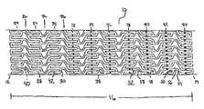
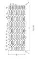
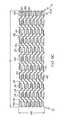
- FIG. 1Ais a side elevation view of the pre-expansion mode of an embodiment of the stent of the present invention
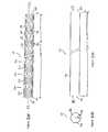
- FIG. 1Bis a cross sectional view of an embodiment of the stent of the present invention.
- FIG. 1Cis a longitudinal cross sectional view of an embodiment of the stent of the present invention.
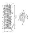
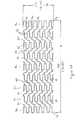
- FIG. 2Ais a scale drawing of the strut pattern of an embodiment of the stent of the present invention.
- FIG. 2Bis an expanded view of a section of the pattern of FIG. 2A ;
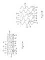
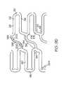
- FIG. 3Ais a schematic illustration of a pre-expansion mode of an embodiment of the stent of the present invention.
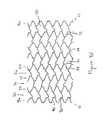
- FIG. 3Bis a schematic illustration of the post-expansion mode of an embodiment of the stent of the present invention.
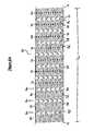
- FIG. 4Ais a scale drawing including dimensions of an embodiment of the stent of the present invention.
- FIG. 4Bis an enlarged section of the scale drawing of FIG. 4A ;
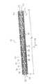
- FIG. 5Ais a scale drawing of an embodiment of the stent of the present invention, the stent having a tapered diameter in its post-expansion mode;
- FIG. 5Bis a scale drawing an embodiment of the stent of the present invention, the stent having a tapered diameter in its post-expansion mode;
- FIG. 5Cis a schematic of an embodiment of the stent of the present invention in an expanded state with a tapered diameter
- FIG. 6Ais a scale drawing of an embodiment of the stent of the present invention with reenforcement expansion columns
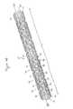
- FIG. 6Bis a perspective view of the embodiment of FIG. 6A ;
- FIG. 6Cis an expanded view of a section of the pattern of FIG. 6A .
- FIG. 7Ais a scale drawing of an embodiment of the stent of the present invention including relief notches at strut joints to increase flexibility of the joints;
- FIG. 7Bis an enlarged region of the embodiment of FIG. 7A ;
- FIG. 7Cis an enlarged view of a single connecting strut joining two expansion strut pairs in accordance with the embodiment of FIG. 7A ;
- FIG. 8Ais a side elevation view of an embodiment of the stent of the present invention.
- FIG. 8Bis a side elevation view of an embodiment of the stent of the present invention, shown as if the stent struts and space there between were transparent;
- FIG. 8Cis a scale drawing of an embodiment of the stent of the present invention.
- FIG. 8Dis a variation of the embodiment of the stent of FIG. 8C ;
- FIG. 8Eis a perspective view of the embodiment of FIG. 8D ;
- FIG. 8Fis a drawing illustrating the post-expansion mode of the stent of the embodiment of FIG. 8D of the present invention.
- FIG. 8Gis an enlarged view of a single connecting strut joining two expansion strut pairs in accordance with an embodiment of the present invention.
- FIG. 9Ais a side elevation view of an embodiment of the stent of the present invention.
- FIG. 9Bis a perspective view of the embodiment of FIG. 9A ;
- FIG. 9Cis a scale drawing of the embodiment of FIG. 9A ;
- FIG. 9Dis an enlarged region of the drawing of FIG. 9C ;
- FIG. 9Eis a scale drawing of an embodiment of the stent of the present invention.
- FIG. 9Fis a scale drawing of an embodiment of the stent of the present invention.
- FIG. 9Gis an enlarged view of a single connecting strut joining two expansion strut pairs in accordance with an embodiment of the present invention.
- FIG. 10Ais a drawing of an alternate geometry of connecting struts and joining struts in accord with the present invention.
- FIG. 10Bis a drawing of an alternate geometry of connecting struts and joining struts in accord with the present invention.
- FIG. 10Cis a drawing of an alternate geometry of connecting struts and joining struts in accord with the present invention.
- FIG. 10Dis a drawing of an alternate geometry of connecting struts and joining struts in accord with the present invention.
- FIG. 10Eis a drawing of an alternate geometry of connecting struts and joining struts in accord with the present invention.
- FIG. 10Fis a drawing of an alternate geometry of connecting struts and joining struts in accord with the present invention.
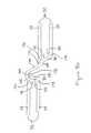
- FIG. 11is a delivery balloon catheter, illustrating a method of deliver of a stent in accord with the present invention.
- FIGS. 1A , 1 B, 1 C, 2 A and 2 BA first embodiment of the present invention is shown in FIGS. 1A , 1 B, 1 C, 2 A and 2 B.
- FIG. 1Aan elongate hollow tubular stent 10 in an unexpanded state is shown.
- a proximal end 12 and a distal end 14define a longitudinal length 16 of stent 10 .
- the longitudinal length 16 of the stent 10can be as long as 100 mm or longer.
- a proximal opening 18 and a distal opening 20connect to an inner lumen 22 of stent 10 .
- Stent 10can be a single piece, without any seams or welding joints or may include multiple pieces.
- Stent 10is constructed of two to fifty or more expansion columns or rings 24 connected together by interspersed connecting strut columns 26 .
- the first column on the proximal end 12 and the last column on the distal end 14 of stent 10are expansion columns 24 .
- Expansion columns 24are formed from a series of expansion struts 28 , and joining struts 30 .
- Expansion struts 28are thin elongate members arranged so that they extend at least in part in the direction of the longitudinal axis of stent 10 .
- expansion struts 28are reoriented such that they extend in a more circumferential direction, i.e along the surface of cylindrical stent 10 and perpendicular to its longitudinal axis. Reorientation of expansion struts 28 causes stent 10 to have an expanded circumference and diameter.
- expansion struts 28 of unexpanded stent 10are seen to extend substantially parallel to the longitudinal axis of stent 10 .
- Expansion struts 28are joined together by joining struts 30 to form a plurality of expansion strut pairs 32 .
- Expansion strut pairshave a closed end 34 and an open end 36 .
- Additional joining struts 30join together expansion struts 28 of adjacent expansion strut pairs 32 , such that expansion struts 28 are joined alternately at their proximal and distal ends to adjacent expansion struts 28 to form expansion columns 24 .
- Each expansion column 24contains a plurality, typically eight to twenty, twenty to sixty, or larger of expansion struts 28 .
- Expansion columnsare preferably continuous unbroken ring structures extending around the circumference of the stent 10 ; however, broken structures in which individual struts or pieces of struts are removed from an otherwise continuous expansion column 24 can also be used.
- Connecting struts 38connect adjacent expansion columns 24 forming a series of interspersed connecting strut columns 26 each extending around the circumference of stent 10 .
- Each connecting strut 38joins a pair of expansion struts 28 in an expansion column 24 to an adjacent pair of expansion struts 28 in an adjacent expansion column 24 .
- the ratio of expansion struts 28 in an expansion column 24 to connecting struts 38 in a connecting strut column 26is two to one; however, this ratio in general can be x to 1 where x is greater or less than two.
- 1Abegins with an expansion column 24 on the proximal end 12 and ends with an expansion column 24 on the distal end 14 , if there are n expansion columns 24 with m expansion struts 28 per column, there will be m ⁇ 1 connecting strut columns 26 , and n(m ⁇ 1)/2 connecting struts 38 .
- connecting struts 38 in each connecting strut column 26allows stent 10 to be longitudinally flexibility. Longitudinal flexibility can be further increased by using a narrow width connecting strut, providing additional flexibility and suppleness to the stent as it is navigated around turns in a natural blood vessel.
- a cell space or geometric cellis an empty region on the surface of stent 10 , completely surrounded by one or a combination of stent struts, including expansion struts 28 , connecting struts 38 , or joining struts 30 .
- Asymmetrical cell spaces 40are cell spaces which have no geometrical symmetry i.e. no rotation, reflection, combination rotation and reflection or other symmetry.
- Asymmetrical cell spaces 40have an asymmetrical geometric configuration.
- Asymmetrical cell spaces 40 in FIG. 1Aare surrounded by a first expansion strut pair 32 in a first expansion column 24 , a first connecting strut 38 , a second expansion strut pair 32 in an adjacent expansion column 24 , a first joining strut 30 , a second connecting strut 38 , and a second joining strut 30 .
- expansion strut pairs 32 of asymmetrical cell space 40may be circumferentially offset i.e. have longitudinal axes that are not collinear and have their open ends 36 facing each other.
- the space between two expansion struts of an expansion strut pair 32is known as a loop slot 42 .
- FIG. 1Bshows inner lumen 22 , radius 44 and stent wall 46 of stent 10 .
- Stent wall 46consists of stent struts including expansion struts 28 , connecting struts 38 and joining struts 30 .
- FIG. 1Cshows, proximal end 12 , distal end 14 , longitudinal length 16 , inner lumen 22 , and stent wall 46 of stent 10 .
- Inner lumen 22is surrounded by stent wall 46 which forms the cylindrical surface of stent 10 .
- joining struts 30 of stent 10are seen to extend at an angle to the expansion struts 28 , forming a narrow angle 48 with one expansion strut 28 in an expansion strut pair 32 and a wide angle 50 with the other expansion strut 28 of an expansion strut pair 32 .
- Narrow angle 48is less than ninety degrees
- wide angle 50is greater than ninety degrees.
- Joining struts 30extend both longitudinally along the longitudinal axis of stent 10 and circumferentially, along the surface of the stent 10 perpendicular to its longitudinal axis.
- Expansion strut spacing 52 between adjacent expansion struts 28 in a given expansion column 24are uniform in stent 10 of FIGS. 2A and 2B ; however, non-uniform spacings can also be used. Expansion strut spacings 52 can be varied, for example, spacings 52 between adjacent expansion struts 28 in an expansion column 24 can alternate between a narrow and a wide spacings. Additionally, spacings 52 in a single expansion column 24 can differ from other spacings 52 in other columns 24 .
- FIGS. 2A and 2Bshow an arrangement of expansion struts 28 such that collinear, parallel adjacent loop slots 42 are formed, but non-collinear and non-parallel loop slots 42 can also be used.
- loop slots 42need not be the same among loop slots of a single or multiple expansion columns 24 .
- the shape of loop slots 42can be altered by changing the orientation or physical dimensions of the expansion struts 28 and/or joining struts 30 which connect expansion struts 28 of expansion strut pairs 32 defining the boundaries of loop slots 42 .
- Connecting struts 38couple adjacent expansion columns 24 , by connecting the distal end of an expansion strut pair in one expansion column 24 to the proximal end of an adjacent expansion strut pair 32 in a second expansion column 24 .
- Connecting struts 38 of FIGS. 2A and 2Bare formed from two linear sections, a first linear section 54 being joined at its distal end to a second linear section 56 at its proximal end to form a first slant angle 58 .
- the first linear section 54 of a connecting strut 38is joined to expansion strut 28 at the point where joining strut 30 makes narrow angle 48 with expansion strut 28 .
- First linear section 54extends substantially collinear to joining strut 30 continuing the line of joining strut 30 into the space between expansion columns 24 .
- the distal end of the first linear section 54is joined to the proximal end of the second linear section 56 forming slant angle 58 .
- Second linear section 56extends substantially parallel to expansion struts 28 connecting at its distal end to joining strut 30 in an adjacent expansion column 24 .
- the distal end of second linear section 56attaches to expansion strut 28 at the point where joining strut 30 makes narrow angle 48 with expansion strut 28 .
- joining strut 30can have a second slant angle with a width that can be the same or different from the width of the first slant angle.
- FIGS. 2A and 2Bshow connecting struts 38 and joining struts 30 slanted relative to the longitudinal axis of stent 10 , with the circumferential direction of the slanted struts alternating from column to adjacent column.
- Circumferential directionrefers to the handedness with which the slanted struts wind about the surface of the stent 10 .
- the circumferential direction of the slant of connecting strut first linear sections 54 in a connecting strut column 26is opposite the circumferential direction of the slant of connecting strut first linear sections 54 in an adjacent connecting strut column 26 .
- circumferential direction of the slant of joining struts 30 in an expansion column 24is opposite the circumferential direction of the slant of joining struts 30 in an adjacent expansion column 24 .
- Alternating circumferential slant directions of connecting struts 38 and joining struts 30prevents axial warping of stent 10 during deliver and expansion.
- Other non-alternating slant direction patternscan also be used for connecting struts 38 or joining struts 30 or both.
- FIGS. 3A and 3Bshow a schematic illustration of a stent design according to the present invention in an unexpanded and expanded state respectively.
- the designis depicted as a flat projection, as if stent 10 were cut lengthwise parallel to its longitudinal axis and flattened out.
- the connecting struts 38consist of first and second linear sections 54 and 56 forming slant angle 58 at pivot point 60 .
- An asymmetrical cell space 40is formed by expansion strut pairs 32 , connecting struts 38 and joining struts 30 . Multiple interlocking asymmetrical cell spaces 40 make up the design pattern.
- the expansion strut pairs 32spread apart at their open ends 36 , shortening the length of expansion struts 28 along the longitudinal axis of the cylindrical stent.
- the longitudinal shortening of expansion struts 28 during expansionis countered by the longitudinal lengthening of connecting struts 38 .
- the widening of slant angle 58 during expansionstraightens connecting struts 38 and lengthens the distance between the coupled expansion strut pairs 32 .
- the widening of the slant angle of connecting struts 38substantially compensates for the longitudinal shortening of expansion struts 28 .
- the stenthas substantially constant unexpanded and expanded longitudinal lengths.
- each expansion column 24becomes circumferentially stretched, enlarging the space between struts.
- the interlinking of expansion columns 24 by connecting struts 38 that have been straightened through the expansion processgives the stent 10 a high radial support strength.
- the entire stent 10 when expandedis unitized into a continuous chain mesh of stretched expansion columns 24 and connecting strut columns 26 forming an asymmetrical interlocking cell geometry which resists collapse both axially and radially. When the stent is expanded it has increased rigidity and fatigue tolerance.
- connecting struts 38 at pivot points 60allows increased longitudinal flexibility of the stent.
- the tangent plane of a specific connecting strut 38refers to the plane substantially tangent to the cylindrical surface of the stent at that connecting strut 38 .
- the width of connecting struts 38can be twice as wide as a thickness. Preferably, a one-to-one ratio is preferred.
- pivot points 60 in connecting struts 38provide connecting struts 38 a flexible joint about which to more easily bend increasing longitudinal flexibility of the stent.
- stent 10has a length 16 of 33.25 mm and an uncrimped and unexpanded circumference 88 of 5.26 mm.
- Fifteen expansion columns 24are interspersed with connecting strut columns 26 .
- Each expansion column 24consists of twelve expansion struts 28 joined alternately at their proximal and distal ends by joining struts 30 forming six expansion strut pairs 32 .
- Expansion struts 28are aligned parallel to the longitudinal axis of cylindrical stent 10 .
- Joining struts 30form a narrow angle 48 and a wide angle 50 with the respective expansion struts 28 of expansion strut pairs 32 .
- Adjacent expansion columns 24employ alternating circumferential slant directions of joining struts 30 .
- expansion strut width 62is 0.20 mm
- expansion strut length 64is 1.51 mm
- connecting strut width 66is 0.13 mm.
- Distance 68 from the outer edge of a first expansion strut 28 to the outer edge of a second adjacent expansion strut 28 in the same expansion column 24is 0.64 mm, leaving a loop slot width 70 of 0.24 mm.
- connecting struts 38consist of a slanted first linear section 54 joined to a second linear section 56 at a slant angle 58 .
- First linear section 54is slightly longer than second linear section 56 and is attached at its proximal end to an expansion strut 28 in an expansion column 24 .
- the attachment of the proximal end of first linear section 54 to expansion strut 28is at the point where joining strut 30 makes narrow angle 48 with expansion strut 28 .
- First linear section 54extends substantially collinear to joining strut 30 attaching at its distal end to the proximal end of second linear section 56 to form slant angle 58 .
- Second linear section 56extends substantially collinear to expansion struts 28 , attaching at its distal end to an expansion strut 28 in an adjacent expansion column 24 . The attachment occurs at the point where expansion strut 28 forms narrow angle 48 with joining strut 30 . Joining struts 30 and connecting strut first linear sections 54 slant in alternating circumferential directions from column to adjacent column.
- connecting struts 38 and expansion struts 28 at the point where narrow angle 48 is formedaids smooth delivery of stent 10 by streamlining the surface of the unexpanded stent and minimizing possible catching points. Bare delivery of stent 10 to the target lesion in a vessel will thus result in minimal snagging or catching as it is navigated through turns and curvatures in the vessel. Stent 10 behaves like a flexible, tubular sled as it is moved forward or backward in the vessel on the delivery catheter, sliding through tortuous vessels and over irregular bumps caused by atherosclerotic plaques inside the vessel lumen.
- Stent 10 of FIGS. 4A and 4Bhas an internal diameter of up to 5.0 mm, while maintaining an acceptable radial strength and fatigue tolerance.
- the crimped stent outer diametercan be as small as 1.0 mm or less depending on the condition of the underlying delivery balloon profile; A small crimped outer diameter is especially important if stent delivery is to be attempted without predilation of the target site.
- the surface of the crimped stentis smooth allowing for no snagging of the stent struts during either forward or backward movement through a vessel.
- FIGS. 5A and 5Cshows a second embodiment of the present invention in which the stent 10 in its expanded form has a gradual taper from proximal end 12 to distal end 14 .
- the shaded segments 72 , 74 , 76 , 78 , 80 , 82 and 84 of expansion struts 28represent regions of expansion struts 28 to be removed. As shown schematically in FIG.
- removal of the shaded segments 72 , 74 , 76 , 78 , 80 , 82 , and 84provides stent 10 with a gradual taper when expanded with distal end 14 having a smaller expanded diameter than proximal end 12 .
- the degree of shortening of the expanded diameter of the stem 10 at a given expansion column 24will be proportional to the length of the removed segment 72 , 74 , 76 , 78 , 80 , 82 , or 84 at that expansion column 24 .
- the shortened expansion struts 28will have a shortened component along the circumference of the stent resulting in a shortened circumference and diameter.
- the tapered diameter portioncan be positioned anywhere along the length of stent 10 , and the tapering can be made more or less gradual by removing appropriately larger or smaller portions of the expansion struts 28 in a given expansion column 24 .
- Taperingis especially important in long stents, longer than 12 mm, since tapering of blood vessels is more pronounced over longer lengths.
- a long stent with a uniform stent diametercan only be matched to the target vessel diameter over a short region. If the proximal vessel size is matched with the stent diameter, the expanded distal end of the stent will be too large for the natural vessel and may cause an intimal dissection of the distal vessel by stent expansion. On the other hand, if the distal vessel size is matched with the stent diameter, the proximal end of the expanded stent will be too small to set inside the vessel lumen. It is therefore desirable to have a stent with a tapered expanded diameter.
- Another way to achieve a tapered expanded stentis to change the stiffness of the stent struts, expansion struts, connecting struts or joining struts such that the stiffness of the struts varies along the length of the stent.
- the stiffness of the strutscan be changed by altering length, width or thickness, adding additional stiffening material, using a chemical or mechanical means to alter the physical properties of the stent material, or applying one or a series of elastic elements about the stent.
- FIG. 5Bshows an embodiment of the present invention where the stiffness of the connecting struts is change by altering the length of the connecting struts as described above.
- connection struts 38represent regions of connection struts 38 to be removed in order to provide the tapered configuration described.
- a stent having this configurationis shown in FIG. 5C in the expanded state.
- a matching tapered balloon catheterwould ideally be made for delivery and deployment of the tapered diameter stent.
- the method of using a tapered matching balloon catheter with a tapered diameter stentis within the scope of the present invention.
- Using a tapered balloon to expand a non-tapered stentwill also achieve a tapered expanded stent; however, since no metal is removed from the stent, the stent is tapered as a result of incomplete expansion. The stent will therefore have increased metal fraction at the tapered end resulting in increased risk of acute thrombosis.
- Metal fractionis the propostion of the surface of the expanded stent covered by the stent strut material. Shortening the expansion struts as shown in FIGS. 5A and 5C allows for a tapered expanded stent with substantially constant metal fraction along its length.
- a third embodiment of the present invention shown in FIGS. 6A , 6 B and 6 Chas multiple reinforcement expansion columns 86 placed along the length of the stent 10 .
- the reinforcement columns 86are placed along the stent length to provide additional localized radial strength and rigidity to stent 10 . Additional strength and rigidity are especially important at the ends of the stent to prevent deformation of the stent both during delivery and after placement. During delivery the stent ends can catch on the vessel wall possibly deforming the unexpanded stent and altering its expansion characteristics.
- the catheter or guidewirecan catch on the stent ends pulling the stent away from the vessel wall and possibly damaging and/or blocking the vessel
- the specific variation of the third embodiment of stent 10 depicted FIGS. 6A , 6 B and 6 Chas a length 16 of 20.70 mm and an uncrimped and unexpanded circumference 88 of 5.26 mm.
- the stent 10consists of six expansion columns 24 and three reinforcement expansion columns 86 , each consisting respectively of twelve expansion struts 28 or reenforcement expansion struts 90 .
- the reenforcement expansion columns 86are positioned one at either end, and one along the length of the stent 10 .
- the expansion strut width 62is 0.15 mm
- reenforcement expansion strut width 92is 0.20 mm
- the connecting strut width 66is 0.10 mm.
- the narrow angle 48 formed by joining strut 30 and expansion strut 28is 75 degrees
- the narrow angle 94 formed by reenforcement joining strut 96 and reenforcement expansion strut 90is 60 degrees.
- reenforcement expansion columns 86can also be used and fall within the scope of the present invention.
- a tapercan also be programmed into the reenforced stent 10 by shortening expansion struts 28 and reenforcement expansion struts 90 in appropriate expansion columns 24 and 86 .
- a fourth embodiment of the present inventionshown in the FIGS. 7A , 7 B and 7 C, is similar to the third embodiment but has the added feature of relief notches 98 and 100 .
- a relief notchis a notch where metal has been removed from a strut, usually at a joint where multiple struts are connected. Relief notches increase flexibility of a strut or joint by creating a thinned, narrow region along the strut or joint.
- Relief notch 98is formed at the joint formed between first linear section 54 of connecting strut 38 and expansion strut 28 .
- Relief notch 100is formed at the joint between second linear section 56 of connecting strut 38 and expansion strut 28 .
- Relief notchesgive added flexibility to the unexpanded stent and prevents warping at the joints when the stent is expanded. This results in a smooth surface modulation to the expanded stent frame.
- Relief notchescan be placed at other joints and can be included in any of the previously mentioned embodiments.
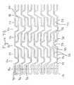
- FIGS. 8A and 8Bshow a side elevation view of a variation of the fifth embodiment of the stent of the present invention.
- a four piece slanted connecting strut 38is used to couple the corner of an expansion strut pair 32 in one expansion column 24 to the joining strut 30 of a circumferentially offset expansion strut pair 32 in an adjacent expansion column 24 .
- the expansion struts 28 , joining struts 30 , expansion columns 24 , reenforcement expansion struts 90 , reenforcement joining struts 96 , and reenforcement expansion columns 86are substantially similar to the fourth embodiment of FIG. 6A .
- Connecting struts 38 in connecting strut columns 26however, have an altered geometry and connectivity; described in more detail below.
- FIG. 8Ashows only the stent struts on the front half of the stent surface.
- the stent struts on the rear half of the stent surfaceare not shown. The stent appears as it would if the stent struts and space there between were opaque.
- FIG. 8Bshows all stent struts from both the front and rear halves. The stent appears as it would if the stent struts and the space there between were transparent.
- a first variation of a fifth embodiment of the present inventionshown in FIG. 8C consists of a stent 10 with twelve expansion columns 24 , four reenforcement expansion columns 86 , and fifteen connecting strut columns 26 .
- the stent 10has a length 16 of 31.96 mm, and an unexpanded circumference 88 of 5.26 mm.
- Connecting struts 38 shown in an enlarged view in FIG. 8Gare made up of four linear sections, a proximal end section 162 , first and second intermediate sections 164 and 166 respectively and a distal end section 168 forming three slant angles 170 , 172 and 174 .
- the proximal end of proximal section 162is attached to a corner 176 of an expansion strut pair 32 of an expansion column 24 . Corner 176 is formed where joining strut 30 makes narrow angle 48 with expansion strut 28 .
- a second corner 178 of expansion strut 32is formed where joining strut 30 makes wide angle 50 with expansion strut 28 .
- Corners 176 and 178can have an angular shape formed by joining linear expansion struts 28 and joining struts 30 , or preferably corners 176 and 178 are rounded to remove sharp edges and provide increased flexibility. Additionally rounded corners provide stent 10 with greater expandability and reduce stress in the stent strut material at the corners in the expanded stent.
- Proximal end section 162 of connecting strut 38extends from corner 176 and is attached at its distal end to first intermediate section 164 forming slant angle 170 .
- First intermediate section 164extends from proximal end section 162 such that first intermediate section 164 is parallel to expansion struts 28 and is connected at its distal end to the proximal end of second intermediate section 166 forming slant angle 172 .
- Second intermediate section 166extends in a slanted orientation relative to the longitudinal axis of stent 10 , extending both longitudinally along and circumferentially about stent 10 .
- second intermediate section 166is parallel to joining strut 30 of the circumferentially offset expansion strut pair 32 in adjacent expansion column 24 .
- Second intermediate section 166attaches at its distal end to the proximal end of distal end section 168 forming slant angle 174 .
- Distal end section 168extends from second intermediate section 166 attaching at its distal end to joining strut 30 of circumferentially offset expansion strut pair 32 of adjacent expansion column 24 .
- the attachmentis at a point intermediate corners 176 and 178 , where joining strut 30 forms narrow angle 48 and wide angle 50 respectively with expansion struts 28 .
- connection point of distal end section 168 to joining strut 30is closer to corner 176 than corner 178 .
- the connection pointis one to two or more expansion strut widths from corner 176 .
- Offsetting the connection point of distal end section 168 to joining strut 30 from corner 176 to a point intermediate corner 176 and corner 178reduces warping of the expanded stent 10 , resulting in a smooth surface modulation and reduced risk of thrombosis. Additionally, this design provides a longer total straightened length of connecting strut 38 , which further reduces foreshortening of stent 10 during expansion.
- a second variation of a fifth embodiment of the present inventionshown in an unexpanded form in FIGS. 8D , 8 E and in an expanded form in FIG. 8F consists of a stent 10 with six expansion columns 24 , two reenforcement expansion columns 86 , and seven connecting strut columns 26 .
- the stent 10has a length 16 of 15.04 mm, and an unexpanded circumference 88 of 5.26 mm.
- the stent design 10is substantially similar to the design of the first variation of the fifth embodiment of FIG. 8C with a reduced number of expansion columns, reenforcement expansion columns, and connecting strut columns.
- FIG. 8Fillustrates a portion of the expanded stent 10 of the second variation of the fifth embodiment.
- the expansion struts 28are spread apart circumferentially, increasing the separation at the open end 36 of expansion strut pairs 32 resulting in an increase in the circumference of the stent 10 .
- the spreading of the expansion struts 28causes a longitudinal shortening of the expansion columns 24 , which is compensated by a straightening of the connecting struts 38 .
- the slant angles 170 , 172 and 174widen straightening the connection struts 38 , and causing an increase in the separation distance between adjacent expansion columns 24 .
- the asymmetrical interlocking cell geometry of the expanded stentis illustrated in FIG. 8F .
- FIGS. 9A , 9 B, 9 C, 9 D, 9 E, 9 F and 9 Gillustrate a sixth embodiment of the stent of the present invention.
- a three piece slanted connecting strut 38is used to couple the joining strut 30 of an expansion strut pair 32 in one expansion column 24 to the joining strut 30 of a circumferentially offset expansion strut pair 32 in an adjacent expansion column 24 .
- the joints between segments of connecting strut 38are curved forming a smooth rounded shape.
- expansion struts 28 , joining struts 30 , expansion columns 24 , reenforcement expansion struts 90 , reenforcement joining struts 96 , and reenforcement expansion columns 86are substantially similar to the fourth embodiment of FIG. 8A .
- Connecting struts 38 in connecting strut columns 26have an altered geometry and connectivity, described in more detail below.
- a first variation of a sixth embodiment of the present inventionshown in FIGS. 9A , 9 B and 9 C consists of a stent 10 with eight expansion columns 24 , three reenforcement expansion columns 86 , and ten connecting strut columns 26 .
- the stent 10has a length 16 of 20.32 mm.
- Relief notches 204are utilized at the joints between reenforcement expansion struts 90 and reenforcement joining struts 96 in the reenforcement expansion columns 86 at the stent proximal end 12 and distal end 14 .
- Relief notches 204reduce the width of the joints between reenforcement expansion struts 90 and reenforcement joining struts 96 , which reduces stress in the metal at the joints during and after expansion of the stent.
- Relief notches 204are particularly important at the stent ends since the stent ends are especially susceptible to warping during and after expansion.
- Preferably relief notches 204reduce the joint widths, such that the joint widths are substantially the same as the thickness of stent wall 46 (see FIGS. 1B and 1C ).
- Connecting struts 38 shown in an enlarged view in FIG. 9Dare made up of three linear sections, a proximal end section 194 , an intermediate section 196 and a distal end section 198 forming two slant angles 200 , 202 .
- the connecting struts 38have wide radii of curvature at the joints between connecting strut sections 194 , 196 and 198 .
- the shape of connecting strut 38is thus curved or wavy rather than jagged and angular.
- the slant angles 200 and 202are defined by linearly extrapolating proximal end section 194 , intermediate section 196 and distal end section 198 , as shown by the dotted lines in FIG. 9D .
- FIG. 9Eshows a variation of the connecting strut design of the sixth embodiment of the present invention.
- the connecting strut 38 of FIG. 9Ehas smaller radii of curvature at the joints between proximal end section 194 , intermediate section 196 and distal end section 198 .
- Connecting strut 38 of FIG. 9Eis thus more jagged and angular than that of FIG. 9D .
- proximal end of proximal section 194is attached to joining strut 30 of expansion strut pair 32 intermediate corners 176 and 178 .
- Proximal end section 194 of connecting strut 38extends from joining strut 30 and is attached at its distal end to intermediate section 196 forming slant angle 200 .
- Intermediate section 196extends from proximal end section 194 in a slanted orientation relative to the longitudinal axis of stent 10 , extending both longitudinally along and circumferentially about stent 10 .
- Intermediate section 196is preferably parallel to joining struts 30 of coupled expansion strut pairs 32 .
- Intermediate section 196is connected at its distal end to the proximal end of distal end section 198 forming slant angle 202 .
- Distal end section 198extends from second intermediate section 196 attaching at its distal end to joining strut 30 of circumferentially offset expansion strut pair 32 of adjacent expansion column 24 .
- the attachmentis at a point intermediate corners 176 and 178 , where joining strut 30 forms narrow angle 48 and wide angle 50 respectively with expansion struts 28 .
- connection point of proximal end section 194 and distal end section 198 to joining struts 30is closer to corner 176 than corner 178 .
- connection pointis one to two or more expansion strut widths from corner 176 .
- Offsetting the connection point of distal end section 198 to joining strut 30 from corner 176 to a point intermediate corner 176 and corner 178reduces warping of the expanded stent 10 , resulting in a smooth surface modulation and reduced risk of thrombosis. Additionally, this design provides a longer total straightened length of connecting strut 38 , which further reduces foreshortening of stent 10 during expansion.
- the connecting strut 38 of the sixth embodimenthas one hundred and eighty degree rotational symmetry about its center.
- the symmetry of the connecting strut 38does not, however, result in a symmetrical cell space as the width of loop slots 42 connected in each cell space are different.
- Adjacent loop slots 42 in each expansion columnhave alternating narrow and wide widths, preserving the asymmetry of the cell spaces.
- Introduction of one or many symmetrical cell spacescan be achieved in this design e.g. by providing uniform loop slot width to loop slots in adjacent expansion columns 24 contained in the same cell space.
- completely non-uniform cell space patterns utilizing symmetric or asymmetric cell spacescan be achieved e.g. by providing non-uniform variations in the widths of loop slots 42 .
- a second variation of a sixth embodiment of the present inventionshown in an unexpanded form in FIG. 9F consists of a stent 10 with six 10 expansion columns 24 , three reenforcement expansion columns 86 , and eight connecting strut columns 26 .
- the stent 10has a length 16 of 16.00 mm, and an unexpanded circumference 88 of 5.26 mm.
- the stent design 10is substantially similar to the design of the first variation of the sixth embodiment of FIGS. 9A , 9 B and 9 C with a reduced number of expansion columns 24 and connecting strut columns 26 .
- a third variation of a sixth embodiment of the present inventionshown in an unexpanded form in FIG. 9F consists of a stent 10 with twelve expansion columns 24 , four reenforcement expansion columns 86 , and fifteen connecting strut columns 26 .
- the stent 10has a length 16 of 30.01 mm, and an unexpanded circumference 88 of 5.26 mm.
- the stent design 10is substantially similar to the design of the first variation of the sixth embodiment of FIGS. 9A , 9 B and 9 C with an increased number of expansion columns 24 reenforcement expansion columns 86 and connecting strut columns 26 .
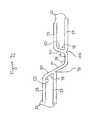
- FIGS. 10A , 10 B, 10 C, 10 D, 10 E and 10 Fillustrate some examples of alternate connecting strut designs which can be used in any of the previously discussed embodiments.
- FIG. 10Ashows a rounded loop connecting strut 38 which joins two circumferentially offset expansion strut pairs 32 in adjacent expansion columns. Expansion struts 28 in each expansion strut pair 32 are joined by a joining strut 30 . Joining struts 30 are slanted such as to form a narrow angle 48 and a wide angle 50 with the expansion struts 28 they connect.
- the rounded loop connecting strut 38connects expansion struts 28 at the point where narrow angle 48 is formed between expansion struts 28 and joining struts 30 .
- the slopes of the rounded connecting strut 38 at its proximal end 102 and distal end 104substantially match the slopes of the joining struts 30 connecting the pairs of expansion struts 28 .
- the rounded loop connecting strut 38thus blends smoothly into the joining struts 30 .
- the rounded loop connecting strut 38has a first radius of curvature 106 and a second radius of curvature 108 .
- a rounded loop connecting strut 38joins two circumferentially offset expansion strut pairs 32 in adjacent expansion columns. Expansion struts 28 in each expansion strut pair 32 are joined by a joining strut 30 . Joining struts 30 are at right angles to the expansion struts 28 they connect. The rounded loop connecting strut 38 connects to expansion struts 28 at the same point as joining struts 30 .
- the rounded connecting strut 38has a first radius of curvature 106 and a second radius of curvature 108 such that it connects circumferentially offset expansion strut pairs 32 .
- connecting strut 38joins two circumferentially offset expansion strut pairs 32 in adjacent expansion columns. Expansion struts 28 in each expansion strut pair 32 are joined by a joining strut 30 . Joining struts 30 are slanted such as to form a narrow angle 48 and a wide angle 50 with the expansion struts 28 they connect.
- the connecting strut 38connects expansion struts 28 at the point where narrow angle 48 is formed between expansion strut 28 and joining strut 30 .
- the connecting strut 38is made up of three linear sections 110 , 112 , and 114 forming two slant angles 116 and 118 .
- the proximal end of section 110is attached to expansion strut 28 at the point where joining strut 30 forms narrow angle 48 with expansion strut 28 .
- Section 110extends substantially collinear to joining strut 30 and is attached at its distal end to intermediate section 112 forming slant angle 116 .
- Intermediate section 112extends at an angle to section 110 such that intermediate section 112 is substantially parallel to expansion struts 28 and is connected at its distal end to the proximal end of distal section 114 forming slant angle 118 .
- Distal section 114extends at an angle such that it is substantially collinear to joining strut 30 of the adjacent expansion strut pair 32 . Distal section 114 attaches at its distal end to expansion strut 28 of the adjacent expansion strut pair 32 , at the point where joining strut 30 forms narrow angle 48 with expansion strut 28 .
- a connecting strut 38joins two circumferentially offset expansion strut pairs 32 in adjacent expansion columns. Expansion struts 28 in each expansion strut pair 32 are joined by a joining strut 30 . Joining struts 30 are at right angles to the expansion struts 28 they connect. The connecting strut 38 connects to expansion struts 28 at the same point as joining struts 30 .
- the connecting struts 38 of FIGS. 10D and 10Eare made up of multiple connecting strut sections connected end to end to form a jagged connecting strut 38 with multiple slant angles, coupling expansion strut pair 32 to adjacent expansion strut pair 32 .
- the connecting strut of FIG. 10Dis made up of three connecting strut sections, a proximal section 120 , an intermediate section 122 and a distal section 124 defining two slant angles 126 and 128
- the connecting strut of FIG. 10Econsists of four connecting strut sections, a proximal section 130 , intermediate sections 132 and 134 , and a distal section 136 defining three slant angles 138 , 140 and 142 .
- connecting strut section 134can be modified by replacing connecting strut section 136 by the dotted connecting strut section 144 to give another possible geometry of connecting struts 38 .
- connecting strut 38joins two circumferentially offset expansion strut pairs 32 in adjacent expansion columns.
- Expansion struts 28 in each expansion strut pair 32are joined by a joining strut 30 .
- Joining struts 30are slanted such as to form a narrow angle 48 and a wide angle 50 with the expansion struts 28 they connect.
- Connecting strut 38is made up of four linear sections, a proximal end section 180 , first and second intermediate sections 182 and 184 respectively and a distal end section 186 forming three slant angles 188 , 190 and 192 .
- the proximal end of section 180is attached to corner 176 at the point where joining strut 30 forms narrow angle 48 with expansion strut 28 .
- Proximal end section 180extends at an angle to joining strut 30 and is attached at its distal end to first intermediate section 182 forming slant angle 188 .
- First intermediate section 182extends at an angle to proximal end section 180 such that first intermediate section 182 is substantially parallel to expansion struts 28 and is connected at its distal end to the proximal end of second intermediate section 184 forming slant angle 190 .
- Second intermediate section 184is substantially longer than the first intermediate section 182 .
- Second intermediate section 184extends at an angle such that it is substantially collinear to joining strut 30 of the adjacent expansion strut pair 32 .
- Second intermediate section 184attaches at its distal end to the proximal end of distal end section 186 forming slant angle 192 .
- Distal end section 186extends in a slightly sloping orientation relative to expansion struts 28 , attaching to corner 176 of expansion strut pair 32 where joining strut 30 forms narrow angle 48 with expansion strut 28 .
- Relief notches 206are formed at the joint between distal end segment 186 of connecting strut 38 and corner 176 of expansion strut pair 32 to increase flexibility of the unexpanded stent and prevent warping when the stent is expanded.
- connecting struts and joining strutsthere are many possible arrangements of connecting struts and joining struts consistent with the present invention; the above examples are not intended to be an exhaustive list.
- connecting strut sectionsneed not be linear but may contain one or many radii of curvature
- connecting strut sectionsmay each have a different longitudinal axis
- the joint between connecting strut sectionsneed not be jagged or sharp, but rather can be smooth containing one or multiple radii of curvature
- relief notchesmay be present at any of the strut joints.
- the stent of the present inventionis ideally suited for application in coronary vessels although versatility in the stent design allows for applications in non-coronary vessels, the aorta, and nonvascular tubular body organs.
- Typical coronary vascular stentshave expanded diameters that range from 2.5 to 5.0 mm.
- a stent with high radial strength and fatigue tolerance that expands to a 5.0 mm diametermay have unacceptably high stent metal fraction when used in smaller diameter vessels. If the stent metal fraction is high, the chances of acute thrombosis and restenosis potential will increase. Even with the same metal fraction a smaller caliber vessel is more likely than a larger one to have a high rate of thrombosis.
- stents for coronary applicationfor example, small vessels stents for use in vessels with diameters from 2.5 mm to 3.0 mm, and large vessel stents for use in vessels with diameters from 3.0 mm to 5.0 mm.
- small vessels stentsfor use in vessels with diameters from 2.5 mm to 3.0 mm
- large vessel stentsfor use in vessels with diameters from 3.0 mm to 5.0 mm.
- the stent of the present inventioncan be made using a CAM-driven laser cutting system to cut the stent pattern from a stainless steel tube.
- the rough-cut stentis preferably electro-polished to remove surface imperfections and sharp edges.
- Other methods of fabricating the stentcan also be used such as EDM, photo-electric etching technology, or other methods.
- Any suitable materialcan be used for the stent including other metals and polymers so long as they provide the essential structural strength, flexibility, biocompatibility and expandability.
- the stentis typically at least partially plated with a radiopaque metal, such as gold, platinum, tantalum or other suitable metal. It is preferred to plate only both ends of the stent by localized plating; however, the entire stent or other regions can also be plated. When plating both ends, one to three or more expansion columns on each end of the stent are plated to mark the ends of the stent so they can be identified under fluoroscopy during the-stenting procedure. By plating the stent only at the ends, interference of the radiopaque plating material with performance characteristics or surface modulation of the stent frame is minimized. Additionally the amount of plating material required is reduced, lowering the material cost of the stent.
- a radiopaque metalsuch as gold, platinum, tantalum or other suitable metal.
- the stentis cleaned, typically with detergent, saline and ultrasonic means that are well-known in the art.
- the stentsare then inspected for quality control, assembled with the delivery balloon catheter, and properly packaged, labeled, and sterilized.
- Stent 10can be marketed as stand alone or as a pre-mounted delivery balloon catheter assembly as shown in FIG. 11 .
- the stent 10is crimped over a folded balloon 146 at the distal end 148 of a delivery balloon catheter assembly 150 .
- the assembly 150includes a proximal end adapter 152 , a catheter shaft 154 , a balloon channel 156 , a guidewire channel 158 , a balloon 146 , and a guidewire 160 .
- Balloon 146can be tapered, curved, or both tapered and curved from a proximal end to a distal end in the expanded state. Additionally stent 10 can be non-tapered or tapered in the expanded state.
- the guidewire 160is inserted into the vein or artery and advanced to the target site.
- the catheter shaft 154is then forwarded over the guidewire 160 to position the stent 10 and balloon 146 into position at the target site.
- the balloon 146is inflated through the balloon channel 156 to expand the stent 10 from a crimped to an expanded state.
- the stent 10provides the desired scaffolding support to the vessel.
- the balloon 146is deflated and the catheter shaft, 154 , balloon 146 , and guidewire 160 are withdrawn from the patient.
- the stent of the present inventioncan be made as short as less than 10 mm in length or as long as 100 mm or more. If long stents are to be used, however, matching length or preferably slightly longer delivery catheter balloons will typically be needed to expand the stents into their deployed positions. Long stents, depending on the target vessel, may require curved long balloons, tapered long balloons or curved and tapered long balloons for deployment. Curved and/or tapered balloons which match the natural curve and taper of a blood vessel reduce stress on the blood vessel during and after stent deployment. This is especially important in many coronary applications which involve stenting in curved and tapered coronary vessels. The use of such curved and/or tapered balloons is within the scope of the present invention.
Landscapes
- Health & Medical Sciences (AREA)
- Engineering & Computer Science (AREA)
- Biomedical Technology (AREA)
- Heart & Thoracic Surgery (AREA)
- Life Sciences & Earth Sciences (AREA)
- Cardiology (AREA)
- Oral & Maxillofacial Surgery (AREA)
- Transplantation (AREA)
- Physics & Mathematics (AREA)
- Vascular Medicine (AREA)
- Optics & Photonics (AREA)
- Animal Behavior & Ethology (AREA)
- General Health & Medical Sciences (AREA)
- Public Health (AREA)
- Veterinary Medicine (AREA)
- Media Introduction/Drainage Providing Device (AREA)
- Prostheses (AREA)
Abstract
Description
Claims (9)
Priority Applications (4)
| Application Number | Priority Date | Filing Date | Title |
|---|---|---|---|
| US10/206,432US8021414B2 (en) | 1996-04-26 | 2002-07-25 | Intravascular stent |
| US10/374,774US20040106985A1 (en) | 1996-04-26 | 2003-02-25 | Intravascular stent |
| US12/192,782US9445926B2 (en) | 1996-04-26 | 2008-08-15 | Intravascular stent |
| US13/232,640US9078778B2 (en) | 1996-04-26 | 2011-09-14 | Intravascular stent |
Applications Claiming Priority (8)
| Application Number | Priority Date | Filing Date | Title |
|---|---|---|---|
| US1748496P | 1996-04-26 | 1996-04-26 | |
| US08/824,866US5954743A (en) | 1996-04-26 | 1997-03-25 | Intravascular stent |
| US08/824,865US6152957A (en) | 1996-04-26 | 1997-03-25 | Intravascular stent |
| US08/824,142US6241760B1 (en) | 1996-04-26 | 1997-03-25 | Intravascular stent |
| US84573497A | 1997-04-25 | 1997-04-25 | |
| US08/845,657US5922021A (en) | 1996-04-26 | 1997-04-25 | Intravascular stent |
| US09/574,077US6770088B1 (en) | 1996-04-26 | 2000-05-18 | Intravascular stent |
| US10/206,432US8021414B2 (en) | 1996-04-26 | 2002-07-25 | Intravascular stent |
Related Parent Applications (1)
| Application Number | Title | Priority Date | Filing Date |
|---|---|---|---|
| US09/574,077ContinuationUS6770088B1 (en) | 1996-04-26 | 2000-05-18 | Intravascular stent |
Related Child Applications (3)
| Application Number | Title | Priority Date | Filing Date |
|---|---|---|---|
| US10/374,774Continuation-In-PartUS20040106985A1 (en) | 1996-04-26 | 2003-02-25 | Intravascular stent |
| US10/374,774ContinuationUS20040106985A1 (en) | 1996-04-26 | 2003-02-25 | Intravascular stent |
| US13/232,640ContinuationUS9078778B2 (en) | 1996-04-26 | 2011-09-14 | Intravascular stent |
Publications (2)
| Publication Number | Publication Date |
|---|---|
| US20020193870A1 US20020193870A1 (en) | 2002-12-19 |
| US8021414B2true US8021414B2 (en) | 2011-09-20 |
Family
ID=56289759
Family Applications (5)
| Application Number | Title | Priority Date | Filing Date |
|---|---|---|---|
| US09/574,077Expired - LifetimeUS6770088B1 (en) | 1996-04-26 | 2000-05-18 | Intravascular stent |
| US09/925,562Expired - Fee RelatedUS7326241B2 (en) | 1996-04-26 | 2001-08-09 | Intravascular stent |
| US09/934,310AbandonedUS20020049493A1 (en) | 1996-04-26 | 2001-08-21 | Intravascular stent |
| US10/206,432Expired - Fee RelatedUS8021414B2 (en) | 1996-04-26 | 2002-07-25 | Intravascular stent |
| US13/232,640Expired - Fee RelatedUS9078778B2 (en) | 1996-04-26 | 2011-09-14 | Intravascular stent |
Family Applications Before (3)
| Application Number | Title | Priority Date | Filing Date |
|---|---|---|---|
| US09/574,077Expired - LifetimeUS6770088B1 (en) | 1996-04-26 | 2000-05-18 | Intravascular stent |
| US09/925,562Expired - Fee RelatedUS7326241B2 (en) | 1996-04-26 | 2001-08-09 | Intravascular stent |
| US09/934,310AbandonedUS20020049493A1 (en) | 1996-04-26 | 2001-08-21 | Intravascular stent |
Family Applications After (1)
| Application Number | Title | Priority Date | Filing Date |
|---|---|---|---|
| US13/232,640Expired - Fee RelatedUS9078778B2 (en) | 1996-04-26 | 2011-09-14 | Intravascular stent |
Country Status (2)
| Country | Link |
|---|---|
| US (5) | US6770088B1 (en) |
| JP (2) | JP4636634B2 (en) |
Families Citing this family (158)
| Publication number | Priority date | Publication date | Assignee | Title |
|---|---|---|---|---|
| US7204848B1 (en) | 1995-03-01 | 2007-04-17 | Boston Scientific Scimed, Inc. | Longitudinally flexible expandable stent |
| US6602281B1 (en)* | 1995-06-05 | 2003-08-05 | Avantec Vascular Corporation | Radially expansible vessel scaffold having beams and expansion joints |
| US20040106985A1 (en) | 1996-04-26 | 2004-06-03 | Jang G. David | Intravascular stent |
| US6235053B1 (en)* | 1998-02-02 | 2001-05-22 | G. David Jang | Tubular stent consists of chevron-shape expansion struts and contralaterally attached diagonal connectors |
| US5954743A (en)* | 1996-04-26 | 1999-09-21 | Jang; G. David | Intravascular stent |
| US6241760B1 (en)* | 1996-04-26 | 2001-06-05 | G. David Jang | Intravascular stent |
| JP4636634B2 (en)* | 1996-04-26 | 2011-02-23 | ボストン サイエンティフィック サイムド,インコーポレイテッド | Intravascular stent |
| WO1998042278A1 (en)* | 1997-03-25 | 1998-10-01 | Jang G David | Intravascular stent |
| US6033433A (en)* | 1997-04-25 | 2000-03-07 | Scimed Life Systems, Inc. | Stent configurations including spirals |
| US6395019B2 (en) | 1998-02-09 | 2002-05-28 | Trivascular, Inc. | Endovascular graft |
| US6241762B1 (en) | 1998-03-30 | 2001-06-05 | Conor Medsystems, Inc. | Expandable medical device with ductile hinges |
| US6682554B2 (en) | 1998-09-05 | 2004-01-27 | Jomed Gmbh | Methods and apparatus for a stent having an expandable web structure |
| US7887578B2 (en)* | 1998-09-05 | 2011-02-15 | Abbott Laboratories Vascular Enterprises Limited | Stent having an expandable web structure |
| US6755856B2 (en) | 1998-09-05 | 2004-06-29 | Abbott Laboratories Vascular Enterprises Limited | Methods and apparatus for stenting comprising enhanced embolic protection, coupled with improved protection against restenosis and thrombus formation |
| EP1132058A1 (en) | 2000-03-06 | 2001-09-12 | Advanced Laser Applications Holding S.A. | Intravascular prothesis |
| US7766956B2 (en)* | 2000-09-22 | 2010-08-03 | Boston Scientific Scimed, Inc. | Intravascular stent and assembly |
| US20010044650A1 (en)* | 2001-01-12 | 2001-11-22 | Simso Eric J. | Stent for in-stent restenosis |
| DE10118944B4 (en) | 2001-04-18 | 2013-01-31 | Merit Medical Systems, Inc. | Removable, essentially cylindrical implants |
| AU2002320456A1 (en) | 2001-07-26 | 2003-02-17 | Alveolus Inc. | Removable stent and method of using the same |
| US7842083B2 (en) | 2001-08-20 | 2010-11-30 | Innovational Holdings, Llc. | Expandable medical device with improved spatial distribution |
| EP1516600B1 (en)* | 2001-09-18 | 2007-03-14 | Abbott Laboratories Vascular Enterprises Limited | Stent |
| US7147661B2 (en)* | 2001-12-20 | 2006-12-12 | Boston Scientific Santa Rosa Corp. | Radially expandable stent |
| JP4331610B2 (en) | 2001-12-20 | 2009-09-16 | トリバスキュラー2,インコーポレイティド | Advanced endovascular graft |
| AU2003239369A1 (en)* | 2002-05-06 | 2003-11-17 | Abbott Laboratories | Endoprosthesis for controlled contraction and expansion |
| US7128756B2 (en)* | 2002-05-08 | 2006-10-31 | Abbott Laboratories | Endoprosthesis having foot extensions |
| US20040054398A1 (en)* | 2002-09-13 | 2004-03-18 | Cully Edward H. | Stent device with multiple helix construction |
| US20040093056A1 (en) | 2002-10-26 | 2004-05-13 | Johnson Lianw M. | Medical appliance delivery apparatus and method of use |
| US7527644B2 (en) | 2002-11-05 | 2009-05-05 | Alveolus Inc. | Stent with geometry determinated functionality and method of making the same |
| US7637942B2 (en) | 2002-11-05 | 2009-12-29 | Merit Medical Systems, Inc. | Coated stent with geometry determinated functionality and method of making the same |
| US7875068B2 (en) | 2002-11-05 | 2011-01-25 | Merit Medical Systems, Inc. | Removable biliary stent |
| US7959671B2 (en) | 2002-11-05 | 2011-06-14 | Merit Medical Systems, Inc. | Differential covering and coating methods |
| US8078274B2 (en) | 2003-02-21 | 2011-12-13 | Dtherapeutics, Llc | Device, system and method for measuring cross-sectional areas in luminal organs |
| US10172538B2 (en) | 2003-02-21 | 2019-01-08 | 3Dt Holdings, Llc | Body lumen junction localization |
| US20100152607A1 (en)* | 2003-02-21 | 2010-06-17 | Kassab Ghassan S | Devices, systems, and methods for measuring parallel tissue conductance, luminal cross-sectional areas, fluid velocity, and/or determining plaque vulnerability using temperature |
| US10568546B2 (en) | 2003-02-21 | 2020-02-25 | 3Dt Holdings, Llc | Devices and methods for sizing valve apertures and luminal organs |
| US10413211B2 (en) | 2003-02-21 | 2019-09-17 | 3Dt Holdings, Llc | Systems, devices, and methods for mapping organ profiles |
| US8388604B2 (en)* | 2003-02-21 | 2013-03-05 | Dtherapeutics, Llc | Devices, systems, and methods for removing contrast from luminal organs |
| US9603545B2 (en)* | 2003-02-21 | 2017-03-28 | 3Dt Holdings, Llc | Devices, systems, and methods for removing targeted lesions from vessels |
| US9462960B2 (en) | 2003-02-21 | 2016-10-11 | 3Dt Holdings, Llc | Impedance devices and methods of using the same to obtain luminal organ measurements |
| US8465452B2 (en)* | 2003-02-21 | 2013-06-18 | 3Dt Holdings, Llc | Devices, systems, and methods for removing stenotic lesions from vessels |
| US8886301B2 (en) | 2003-02-21 | 2014-11-11 | 3Dt Holdings, Llc | Impedance devices for obtaining conductance measurements within luminal organs |
| AU2004216229B2 (en) | 2003-02-21 | 2010-12-09 | Electro-Cat, Llc | System and method for measuring cross-sectional areas and pressure gradients in luminal organs |
| US8406867B2 (en) | 2003-02-21 | 2013-03-26 | Dtherapeutics, Llc | Balloon sizing of valve annulus for percutaneous valves |
| US7818053B2 (en)* | 2003-02-21 | 2010-10-19 | Dtherapeutics, Llc | Devices, systems and methods for plaque type determination |
| US8185194B2 (en)* | 2003-02-21 | 2012-05-22 | Dtherapeutics, Llc | Systems and methods for determining phasic cardiac cycle measurements |
| US7637934B2 (en) | 2003-03-31 | 2009-12-29 | Merit Medical Systems, Inc. | Medical appliance optical delivery and deployment apparatus and method |
| US7604660B2 (en) | 2003-05-01 | 2009-10-20 | Merit Medical Systems, Inc. | Bifurcated medical appliance delivery apparatus and method |
| US7625398B2 (en)* | 2003-05-06 | 2009-12-01 | Abbott Laboratories | Endoprosthesis having foot extensions |
| US7625401B2 (en)* | 2003-05-06 | 2009-12-01 | Abbott Laboratories | Endoprosthesis having foot extensions |
| US11596537B2 (en) | 2003-09-03 | 2023-03-07 | Bolton Medical, Inc. | Delivery system and method for self-centering a proximal end of a stent graft |
| US7763063B2 (en) | 2003-09-03 | 2010-07-27 | Bolton Medical, Inc. | Self-aligning stent graft delivery system, kit, and method |
| US20080264102A1 (en)* | 2004-02-23 | 2008-10-30 | Bolton Medical, Inc. | Sheath Capture Device for Stent Graft Delivery System and Method for Operating Same |
| US8292943B2 (en) | 2003-09-03 | 2012-10-23 | Bolton Medical, Inc. | Stent graft with longitudinal support member |
| US11259945B2 (en) | 2003-09-03 | 2022-03-01 | Bolton Medical, Inc. | Dual capture device for stent graft delivery system and method for capturing a stent graft |
| US7803178B2 (en) | 2004-01-30 | 2010-09-28 | Trivascular, Inc. | Inflatable porous implants and methods for drug delivery |
| JP4852033B2 (en)* | 2004-03-11 | 2012-01-11 | トリバスキュラー インコーポレイテッド | Modular endovascular graft |
| US7763065B2 (en) | 2004-07-21 | 2010-07-27 | Reva Medical, Inc. | Balloon expandable crush-recoverable stent device |
| US7887579B2 (en) | 2004-09-29 | 2011-02-15 | Merit Medical Systems, Inc. | Active stent |
| US8292944B2 (en) | 2004-12-17 | 2012-10-23 | Reva Medical, Inc. | Slide-and-lock stent |
| WO2006090351A1 (en)* | 2005-02-21 | 2006-08-31 | Diagles Ltd | Method and apparatus for mechanical measurement of sphincters and narrowing regions in hollow biological organs |
| US7731654B2 (en) | 2005-05-13 | 2010-06-08 | Merit Medical Systems, Inc. | Delivery device with viewing window and associated method |
| EP2364676B1 (en)* | 2005-06-30 | 2018-12-19 | Abbott Laboratories | Endoprosthesis having foot extensions |
| US9149378B2 (en)* | 2005-08-02 | 2015-10-06 | Reva Medical, Inc. | Axially nested slide and lock expandable device |
| US7914574B2 (en) | 2005-08-02 | 2011-03-29 | Reva Medical, Inc. | Axially nested slide and lock expandable device |
| US8784336B2 (en) | 2005-08-24 | 2014-07-22 | C. R. Bard, Inc. | Stylet apparatuses and methods of manufacture |
| US7404823B2 (en) | 2005-10-31 | 2008-07-29 | Boston Scientific Scimed, Inc. | Stent configurations |
| US7381217B2 (en)* | 2005-12-23 | 2008-06-03 | Boston Scientific Scimed, Inc. | Serpentine stent pattern |
| AU2007208252A1 (en)* | 2006-01-25 | 2007-08-02 | Dtherapeutics | Devices, systems and methods for determining sizes of vessels |
| US20080097620A1 (en) | 2006-05-26 | 2008-04-24 | Nanyang Technological University | Implantable article, method of forming same and method for reducing thrombogenicity |
| US8252041B2 (en)* | 2006-08-23 | 2012-08-28 | Abbott Laboratories | Stent designs for use in peripheral vessels |
| US7988720B2 (en) | 2006-09-12 | 2011-08-02 | Boston Scientific Scimed, Inc. | Longitudinally flexible expandable stent |
| US7794407B2 (en) | 2006-10-23 | 2010-09-14 | Bard Access Systems, Inc. | Method of locating the tip of a central venous catheter |
| US8388546B2 (en) | 2006-10-23 | 2013-03-05 | Bard Access Systems, Inc. | Method of locating the tip of a central venous catheter |
| US7704275B2 (en) | 2007-01-26 | 2010-04-27 | Reva Medical, Inc. | Circumferentially nested expandable device |
| US20080269745A1 (en)* | 2007-04-24 | 2008-10-30 | Osteolign, Inc. | Thermo-chemically activated intramedullary bone stent |
| US8128679B2 (en) | 2007-05-23 | 2012-03-06 | Abbott Laboratories Vascular Enterprises Limited | Flexible stent with torque-absorbing connectors |
| US8226701B2 (en) | 2007-09-26 | 2012-07-24 | Trivascular, Inc. | Stent and delivery system for deployment thereof |
| US8066755B2 (en) | 2007-09-26 | 2011-11-29 | Trivascular, Inc. | System and method of pivoted stent deployment |
| US8663309B2 (en) | 2007-09-26 | 2014-03-04 | Trivascular, Inc. | Asymmetric stent apparatus and method |
| US10159557B2 (en) | 2007-10-04 | 2018-12-25 | Trivascular, Inc. | Modular vascular graft for low profile percutaneous delivery |
| US8328861B2 (en) | 2007-11-16 | 2012-12-11 | Trivascular, Inc. | Delivery system and method for bifurcated graft |
| US8083789B2 (en) | 2007-11-16 | 2011-12-27 | Trivascular, Inc. | Securement assembly and method for expandable endovascular device |
| US9521961B2 (en) | 2007-11-26 | 2016-12-20 | C. R. Bard, Inc. | Systems and methods for guiding a medical instrument |
| US9636031B2 (en) | 2007-11-26 | 2017-05-02 | C.R. Bard, Inc. | Stylets for use with apparatus for intravascular placement of a catheter |
| US10751509B2 (en) | 2007-11-26 | 2020-08-25 | C. R. Bard, Inc. | Iconic representations for guidance of an indwelling medical device |
| ES2465915T3 (en) | 2007-11-26 | 2014-06-09 | C.R. Bard, Inc. | Integrated system for intravascular catheter placement |
| US10524691B2 (en) | 2007-11-26 | 2020-01-07 | C. R. Bard, Inc. | Needle assembly including an aligned magnetic element |
| US8849382B2 (en) | 2007-11-26 | 2014-09-30 | C. R. Bard, Inc. | Apparatus and display methods relating to intravascular placement of a catheter |
| US8781555B2 (en) | 2007-11-26 | 2014-07-15 | C. R. Bard, Inc. | System for placement of a catheter including a signal-generating stylet |
| US9649048B2 (en) | 2007-11-26 | 2017-05-16 | C. R. Bard, Inc. | Systems and methods for breaching a sterile field for intravascular placement of a catheter |
| US10449330B2 (en) | 2007-11-26 | 2019-10-22 | C. R. Bard, Inc. | Magnetic element-equipped needle assemblies |
| EP2211773A4 (en) | 2007-11-30 | 2015-07-29 | Reva Medical Inc | Axially-radially nested expandable device |
| US7972373B2 (en)* | 2007-12-19 | 2011-07-05 | Advanced Technologies And Regenerative Medicine, Llc | Balloon expandable bioabsorbable stent with a single stress concentration region interconnecting adjacent struts |
| US8920488B2 (en) | 2007-12-20 | 2014-12-30 | Abbott Laboratories Vascular Enterprises Limited | Endoprosthesis having a stable architecture |
| US8337544B2 (en) | 2007-12-20 | 2012-12-25 | Abbott Laboratories Vascular Enterprises Limited | Endoprosthesis having flexible connectors |
| US8546172B2 (en) | 2008-01-18 | 2013-10-01 | Miasole | Laser polishing of a back contact of a solar cell |
| US8536054B2 (en)* | 2008-01-18 | 2013-09-17 | Miasole | Laser polishing of a solar cell substrate |
| US20090229666A1 (en)* | 2008-03-14 | 2009-09-17 | Jason Stephan Corneille | Smoothing a metallic substrate for a solar cell |
| US8586398B2 (en)* | 2008-01-18 | 2013-11-19 | Miasole | Sodium-incorporation in solar cell substrates and contacts |
| US10898620B2 (en) | 2008-06-20 | 2021-01-26 | Razmodics Llc | Composite stent having multi-axial flexibility and method of manufacture thereof |
| US8206636B2 (en) | 2008-06-20 | 2012-06-26 | Amaranth Medical Pte. | Stent fabrication via tubular casting processes |
| US8206635B2 (en) | 2008-06-20 | 2012-06-26 | Amaranth Medical Pte. | Stent fabrication via tubular casting processes |
| CN102076281B (en) | 2008-06-30 | 2014-11-05 | 波顿医疗公司 | Systems and methods for abdominal aortic aneurysm |
| US9901714B2 (en) | 2008-08-22 | 2018-02-27 | C. R. Bard, Inc. | Catheter assembly including ECG sensor and magnetic assemblies |
| US8437833B2 (en) | 2008-10-07 | 2013-05-07 | Bard Access Systems, Inc. | Percutaneous magnetic gastrostomy |
| EP2331014B1 (en) | 2008-10-10 | 2017-08-09 | Reva Medical, Inc. | Expandable slide and lock stent |
| KR101810379B1 (en) | 2009-02-02 | 2017-12-20 | 코디스 코포레이션 | Flexible stent design |
| US9205177B2 (en)* | 2009-03-04 | 2015-12-08 | Peytant Solutions, Inc. | Stents modified with material comprising amnion tissue and corresponding processes |
| JP5795576B2 (en) | 2009-06-12 | 2015-10-14 | バード・アクセス・システムズ,インコーポレーテッド | Method of operating a computer-based medical device that uses an electrocardiogram (ECG) signal to position an intravascular device in or near the heart |
| US9532724B2 (en) | 2009-06-12 | 2017-01-03 | Bard Access Systems, Inc. | Apparatus and method for catheter navigation using endovascular energy mapping |
| EP2464407A4 (en) | 2009-08-10 | 2014-04-02 | Bard Access Systems Inc | Devices and methods for endovascular electrography |
| US8114149B2 (en)* | 2009-10-20 | 2012-02-14 | Svelte Medical Systems, Inc. | Hybrid stent with helical connectors |
| WO2011097312A1 (en) | 2010-02-02 | 2011-08-11 | C.R. Bard, Inc. | Apparatus and method for catheter navigation and tip location |
| US8706209B2 (en) | 2010-02-05 | 2014-04-22 | 3Dt Holdings, Llc | Devices, systems, and methods for measuring parallel tissue conductance, luminal cross-sectional areas, fluid velocity, and/or determining plaque vulnerability using temperature |
| JP5809237B2 (en) | 2010-04-10 | 2015-11-10 | レヴァ メディカル、 インコーポレイテッドReva Medical, Inc. | Expandable slide lock stent |
| EP2912999B1 (en) | 2010-05-28 | 2022-06-29 | C. R. Bard, Inc. | Apparatus for use with needle insertion guidance system |
| EP4122385A1 (en) | 2010-05-28 | 2023-01-25 | C. R. Bard, Inc. | Insertion guidance system for needles and medical components |
| MX2013001444A (en)* | 2010-08-02 | 2013-03-12 | Cordis Corp | Flexible helical stent having different helical regions. |
| CA2807025C (en) | 2010-08-02 | 2017-01-24 | Cordis Corporation | Flexible helical stent having intermediate non-helical region |
| WO2012018836A2 (en) | 2010-08-02 | 2012-02-09 | Cordis Corporation | Flexible helical stent having intermediate structural feature |
| AU2011285802B2 (en)* | 2010-08-02 | 2014-09-11 | Cardinal Health 529, Llc | Flexible helical stent having intermediate structural feature |
| WO2012018845A1 (en) | 2010-08-02 | 2012-02-09 | Cordis Corporation | Flexible stent having protruding hinges |
| BR112013002431B1 (en) | 2010-08-20 | 2021-06-29 | C.R. Bard, Inc | SYSTEM FOR RECONFIRMING THE POSITION OF A CATHETER INSIDE A PATIENT |
| US8801693B2 (en) | 2010-10-29 | 2014-08-12 | C. R. Bard, Inc. | Bioimpedance-assisted placement of a medical device |
| EP2667828A4 (en)* | 2011-01-27 | 2016-01-13 | Orbusneich Medical Inc | Medical device for implantation into luminal structures |
| RU2609203C2 (en) | 2011-07-06 | 2017-01-30 | Си.Ар. Бард, Инк. | Determination and calibration of needle length for needle guidance system |
| US9734938B2 (en) | 2011-10-06 | 2017-08-15 | 3Dt Holdings, Llc | Devices and systems for obtaining conductance data and methods of manufacturing and using the same |
| US11373780B2 (en) | 2011-10-06 | 2022-06-28 | 3Dt Holdings, Llc | Methods to generate elongated wires having a metallic substrate thereon and devices comprising the same |
| US9066672B2 (en) | 2011-10-27 | 2015-06-30 | 3Dt Holdings, Llc | Single injection methods for obtaining conductance measurements within luminal organs using impedance devices |
| US8992595B2 (en) | 2012-04-04 | 2015-03-31 | Trivascular, Inc. | Durable stent graft with tapered struts and stable delivery methods and devices |
| JP2015516846A (en) | 2012-04-05 | 2015-06-18 | バード・アクセス・システムズ,インコーポレーテッド | Device and system for navigating and positioning a central venous catheter within a patient |
| US10159531B2 (en) | 2012-04-05 | 2018-12-25 | C. R. Bard, Inc. | Apparatus and methods relating to intravascular positioning of distal end of catheter |
| US11759268B2 (en) | 2012-04-05 | 2023-09-19 | C. R. Bard, Inc. | Apparatus and methods relating to intravascular positioning of distal end of catheter |
| US9498363B2 (en) | 2012-04-06 | 2016-11-22 | Trivascular, Inc. | Delivery catheter for endovascular device |
| US10987208B2 (en)* | 2012-04-06 | 2021-04-27 | Merlin Md Pte Ltd. | Devices and methods for treating an aneurysm |
| WO2014055514A2 (en)* | 2012-10-01 | 2014-04-10 | C.R. Bard, Inc. | Balloon catheter having multiple inflation lumens and related methods |
| JP2016512751A (en)* | 2013-03-14 | 2016-05-09 | パルマズ サイエンティフィック, インコーポレイテッドPalmaz Scientific, Inc. | Integrated medical device, method for manufacturing the same, and method for using the same |
| US9408732B2 (en) | 2013-03-14 | 2016-08-09 | Reva Medical, Inc. | Reduced-profile slide and lock stent |
| US9675257B2 (en) | 2013-03-15 | 2017-06-13 | 3Dt Holdings, Llc | Impedance devices and methods to use the same to obtain luminal organ measurements |
| US9439751B2 (en) | 2013-03-15 | 2016-09-13 | Bolton Medical, Inc. | Hemostasis valve and delivery systems |
| CN105899166B (en)* | 2013-11-06 | 2018-07-06 | 伊诺佩斯生医有限公司 | Wireless Intravascular Stent-Based Electrodes |
| WO2015120256A2 (en) | 2014-02-06 | 2015-08-13 | C.R. Bard, Inc. | Systems and methods for guidance and placement of an intravascular device |
| CN104939947A (en)* | 2014-03-26 | 2015-09-30 | 上海市第六人民医院 | Brain covered stent with endothelial progenitor cell capture function |
| US9895243B2 (en)* | 2014-07-17 | 2018-02-20 | W. L. Gore & Associates, Inc. | Stent having adjacent elements connected by narrow flexible webs |
| US10973584B2 (en) | 2015-01-19 | 2021-04-13 | Bard Access Systems, Inc. | Device and method for vascular access |
| DE102015106052B4 (en)* | 2015-04-21 | 2018-03-01 | Nikola Obradovic | Stent graft |
| WO2016210325A1 (en) | 2015-06-26 | 2016-12-29 | C.R. Bard, Inc. | Connector interface for ecg-based catheter positioning system |
| DE102015118140B4 (en)* | 2015-10-23 | 2019-07-04 | Andramed Gmbh | stent |
| US11000207B2 (en) | 2016-01-29 | 2021-05-11 | C. R. Bard, Inc. | Multiple coil system for tracking a medical device |
| CN105796217B (en)* | 2016-05-17 | 2018-10-26 | 常州市第二人民医院 | A kind of intravascular stent |
| US10575973B2 (en) | 2018-04-11 | 2020-03-03 | Abbott Cardiovascular Systems Inc. | Intravascular stent having high fatigue performance |
| US10932927B2 (en)* | 2018-08-29 | 2021-03-02 | DePuy Synthes Products, Inc. | Stent with longitudinal variable width struts |
| US10992079B2 (en) | 2018-10-16 | 2021-04-27 | Bard Access Systems, Inc. | Safety-equipped connection systems and methods thereof for establishing electrical connections |
| US11832828B2 (en) | 2019-05-24 | 2023-12-05 | Medtronic, Inc. | Left atrial appendage occlusion device |
| CN114126537A (en)* | 2019-12-02 | 2022-03-01 | 爱德华兹生命科学公司 | Frames with different strut widths for prosthetic implants |
| EP4585192A3 (en) | 2020-06-24 | 2025-10-15 | Bolton Medical, Inc. | Anti-backspin component for vascular prosthesis delivery device |
| JP2024510395A (en)* | 2021-02-26 | 2024-03-07 | アナコンダ ビオメッド, エス.エル. | Self-expanding medical device for advancement through the vasculature to an expansion site within a blood vessel |
| US11400299B1 (en) | 2021-09-14 | 2022-08-02 | Rainbow Medical Ltd. | Flexible antenna for stimulator |
Citations (255)
| Publication number | Priority date | Publication date | Assignee | Title |
|---|---|---|---|---|
| US2836181A (en) | 1955-01-17 | 1958-05-27 | Chemstrand Corp | Flexible nylon tube and method for preparing same |
| US3105492A (en) | 1958-10-01 | 1963-10-01 | Us Catheter & Instr Corp | Synthetic blood vessel grafts |
| US3272204A (en) | 1965-09-22 | 1966-09-13 | Ethicon Inc | Absorbable collagen prosthetic implant with non-absorbable reinforcing strands |
| US3490975A (en) | 1965-10-18 | 1970-01-20 | Univ Of Birmingham The | Method of making an artificial artery of wound silicone rubber thread |
| US3509883A (en) | 1967-11-29 | 1970-05-05 | Gen Electric | Expanding cannula |
| US3526228A (en) | 1969-03-24 | 1970-09-01 | Ethicon Inc | Collagen lamina dural prosthesis |
| US3562820A (en) | 1966-08-22 | 1971-02-16 | Bernhard Braun | Tubular sheet and strip form prostheses on a basis of biological tissue |
| US3635215A (en) | 1969-08-14 | 1972-01-18 | Gam Rad | Medical removal hook |
| US3771526A (en) | 1972-02-07 | 1973-11-13 | P Rudie | Anastomosis clamp |
| US3868956A (en) | 1972-06-05 | 1975-03-04 | Ralph J Alfidi | Vessel implantable appliance and method of implanting it |
| US3993078A (en) | 1974-11-04 | 1976-11-23 | Gambro Ag | Insert for use preferably in vascular surgery |
| US4078167A (en) | 1977-02-09 | 1978-03-07 | United Technologies Corporation | Welding shield and plasma suppressor apparatus |
| US4127761A (en) | 1976-10-25 | 1978-11-28 | The Welding Institute | Laser welding |
| US4130904A (en) | 1977-06-06 | 1978-12-26 | Thermo Electron Corporation | Prosthetic blood conduit |
| US4140126A (en) | 1977-02-18 | 1979-02-20 | Choudhury M Hasan | Method for performing aneurysm repair |
| US4141364A (en) | 1977-03-18 | 1979-02-27 | Jorge Schultze | Expandable endotracheal or urethral tube |
| US4164045A (en) | 1977-08-03 | 1979-08-14 | Carbomedics, Inc. | Artificial vascular and patch grafts |
| US4214587A (en) | 1979-02-12 | 1980-07-29 | Sakura Chester Y Jr | Anastomosis device and method |
| US4300244A (en) | 1979-09-19 | 1981-11-17 | Carbomedics, Inc. | Cardiovascular grafts |
| US4313231A (en) | 1980-06-16 | 1982-02-02 | Kabushiki Kaisha Tatebe Seishudo | Vascular prosthesis |
| US4319363A (en) | 1978-05-23 | 1982-03-16 | Vettivetpillai Ketharanathan | Vascular prostheses |
| US4425908A (en) | 1981-10-22 | 1984-01-17 | Beth Israel Hospital | Blood clot filter |
| US4441215A (en)* | 1980-11-17 | 1984-04-10 | Kaster Robert L | Vascular graft |
| US4470407A (en) | 1982-03-11 | 1984-09-11 | Laserscope, Inc. | Endoscopic device |
| US4501264A (en) | 1978-06-02 | 1985-02-26 | Rockey Arthur G | Medical sleeve |
| US4503569A (en) | 1983-03-03 | 1985-03-12 | Dotter Charles T | Transluminally placed expandable graft prosthesis |
| US4512338A (en) | 1983-01-25 | 1985-04-23 | Balko Alexander B | Process for restoring patency to body vessels |
| US4535770A (en) | 1983-11-02 | 1985-08-20 | Lemole Gerald M | Cardiovascular tourniquet |
| US4550447A (en) | 1983-08-03 | 1985-11-05 | Shiley Incorporated | Vascular graft prosthesis |
| US4553545A (en) | 1981-09-16 | 1985-11-19 | Medinvent S.A. | Device for application in blood vessels or other difficultly accessible locations and its use |
| US4560374A (en) | 1983-10-17 | 1985-12-24 | Hammerslag Julius G | Method for repairing stenotic vessels |
| US4580568A (en) | 1984-10-01 | 1986-04-08 | Cook, Incorporated | Percutaneous endovascular stent and method for insertion thereof |
| EP0183372A1 (en) | 1984-10-19 | 1986-06-04 | RAYCHEM CORPORATION (a Delaware corporation) | Prosthetic stent |
| US4597389A (en) | 1982-09-30 | 1986-07-01 | Ibrahim Adel A | Device for removing objects from tubular body passages |
| US4647416A (en) | 1983-08-03 | 1987-03-03 | Shiley Incorporated | Method of preparing a vascular graft prosthesis |
| US4649922A (en) | 1986-01-23 | 1987-03-17 | Wiktor Donimik M | Catheter arrangement having a variable diameter tip and spring prosthesis |
| US4655776A (en) | 1984-01-12 | 1987-04-07 | Oto Enterprises, Inc. | Prostheses for ossicular reconstruction |
| US4655771A (en) | 1982-04-30 | 1987-04-07 | Shepherd Patents S.A. | Prosthesis comprising an expansible or contractile tubular body |
| US4665918A (en) | 1986-01-06 | 1987-05-19 | Garza Gilbert A | Prosthesis system and method |
| US4681110A (en) | 1985-12-02 | 1987-07-21 | Wiktor Dominik M | Catheter arrangement having a blood vessel liner, and method of using it |
| US4693721A (en) | 1984-10-17 | 1987-09-15 | Paul Ducheyne | Porous flexible metal fiber material for surgical implantation |
| US4733665A (en) | 1985-11-07 | 1988-03-29 | Expandable Grafts Partnership | Expandable intraluminal graft, and method and apparatus for implanting an expandable intraluminal graft |
| US4740207A (en) | 1986-09-10 | 1988-04-26 | Kreamer Jeffry W | Intralumenal graft |
| US4760849A (en) | 1985-04-10 | 1988-08-02 | Medinvent S.A. | Planar blank and a coil spring manufactured therefrom |
| US4762128A (en) | 1986-12-09 | 1988-08-09 | Advanced Surgical Intervention, Inc. | Method and apparatus for treating hypertrophy of the prostate gland |
| US4769029A (en) | 1987-06-19 | 1988-09-06 | Patel Jayendrakumar I | Prosthetic graft for arterial system repair |
| US4768507A (en) | 1986-02-24 | 1988-09-06 | Medinnovations, Inc. | Intravascular stent and percutaneous insertion catheter system for the dilation of an arterial stenosis and the prevention of arterial restenosis |
| US4771773A (en) | 1985-06-10 | 1988-09-20 | Medinvent S.A. | Insertion device |
| US4787899A (en) | 1983-12-09 | 1988-11-29 | Lazarus Harrison M | Intraluminal graft device, system and method |
| US4795458A (en) | 1987-07-02 | 1989-01-03 | Regan Barrie F | Stent for use following balloon angioplasty |
| US4795465A (en) | 1987-05-14 | 1989-01-03 | Hood Laboratories | Tracheobronchial stent |
| US4800882A (en) | 1987-03-13 | 1989-01-31 | Cook Incorporated | Endovascular stent and delivery system |
| US4820298A (en) | 1987-11-20 | 1989-04-11 | Leveen Eric G | Internal vascular prosthesis |
| US4830003A (en) | 1988-06-17 | 1989-05-16 | Wolff Rodney G | Compressive stent and delivery system |
| US4842575A (en) | 1984-01-30 | 1989-06-27 | Meadox Medicals, Inc. | Method for forming impregnated synthetic vascular grafts |
| US4848343A (en) | 1986-10-31 | 1989-07-18 | Medinvent S.A. | Device for transluminal implantation |
| US4851009A (en) | 1985-12-16 | 1989-07-25 | Corvita Corporation | Crack prevention of implanted prostheses |
| US4856516A (en) | 1989-01-09 | 1989-08-15 | Cordis Corporation | Endovascular stent apparatus and method |
| US4872874A (en) | 1987-05-29 | 1989-10-10 | Taheri Syde A | Method and apparatus for transarterial aortic graft insertion and implantation |
| US4877030A (en) | 1988-02-02 | 1989-10-31 | Andreas Beck | Device for the widening of blood vessels |
| US4878906A (en) | 1986-03-25 | 1989-11-07 | Servetus Partnership | Endoprosthesis for repairing a damaged vessel |
| US4886062A (en) | 1987-10-19 | 1989-12-12 | Medtronic, Inc. | Intravascular radially expandable stent and method of implant |
| US4913141A (en) | 1988-10-25 | 1990-04-03 | Cordis Corporation | Apparatus and method for placement of a stent within a subject vessel |
| EP0364787A1 (en) | 1988-10-04 | 1990-04-25 | EXPANDABLE GRAFTS PARTNERSHIP a Texas General Partnership | Expandable intraluminal graft |
| US4922905A (en) | 1985-11-30 | 1990-05-08 | Strecker Ernst P | Dilatation catheter |
| US4950227A (en) | 1988-11-07 | 1990-08-21 | Boston Scientific Corporation | Stent delivery system |
| US4950258A (en) | 1988-01-28 | 1990-08-21 | Japan Medical Supply Co., Ltd. | Plastic molded articles with shape memory property |
| US4994071A (en) | 1989-05-22 | 1991-02-19 | Cordis Corporation | Bifurcating stent apparatus and method |
| US5015253A (en) | 1989-06-15 | 1991-05-14 | Cordis Corporation | Non-woven endoprosthesis |
| US5019090A (en) | 1988-09-01 | 1991-05-28 | Corvita Corporation | Radially expandable endoprosthesis and the like |
| US5035706A (en) | 1989-10-17 | 1991-07-30 | Cook Incorporated | Percutaneous stent and method for retrieval thereof |
| US5037392A (en) | 1989-06-06 | 1991-08-06 | Cordis Corporation | Stent-implanting balloon assembly |
| US5059211A (en) | 1987-06-25 | 1991-10-22 | Duke University | Absorbable vascular stent |
| US5064435A (en) | 1990-06-28 | 1991-11-12 | Schneider (Usa) Inc. | Self-expanding prosthesis having stable axial length |
| US5092877A (en) | 1988-09-01 | 1992-03-03 | Corvita Corporation | Radially expandable endoprosthesis |
| EP0335341B1 (en) | 1988-03-28 | 1992-03-04 | EXPANDABLE GRAFTS PARTNERSHIP a Texas General Partnership | Expandable intraluminal graft and apparatus for implanting an expandable intraluminal graft |
| US5104399A (en) | 1986-12-10 | 1992-04-14 | Endovascular Technologies, Inc. | Artificial graft and implantation method |
| US5104404A (en) | 1989-10-02 | 1992-04-14 | Medtronic, Inc. | Articulated stent |
| US5108417A (en) | 1990-09-14 | 1992-04-28 | Interface Biomedical Laboratories Corp. | Anti-turbulent, anti-thrombogenic intravascular stent |
| US5122154A (en) | 1990-08-15 | 1992-06-16 | Rhodes Valentine J | Endovascular bypass graft |
| US5133732A (en) | 1987-10-19 | 1992-07-28 | Medtronic, Inc. | Intravascular stent |
| US5135536A (en) | 1991-02-05 | 1992-08-04 | Cordis Corporation | Endovascular stent and method |
| US5139480A (en) | 1990-08-22 | 1992-08-18 | Biotech Laboratories, Inc. | Necking stents |
| US5147385A (en) | 1989-11-01 | 1992-09-15 | Schneider (Europe) A.G. | Stent and catheter for the introduction of the stent |
| US5147400A (en) | 1989-05-10 | 1992-09-15 | United States Surgical Corporation | Connective tissue prosthesis |
| US5158548A (en) | 1990-04-25 | 1992-10-27 | Advanced Cardiovascular Systems, Inc. | Method and system for stent delivery |
| US5163952A (en) | 1990-09-14 | 1992-11-17 | Michael Froix | Expandable polymeric stent with memory and delivery apparatus and method |
| US5197978A (en) | 1991-04-26 | 1993-03-30 | Advanced Coronary Technology, Inc. | Removable heat-recoverable tissue supporting device |
| EP0540290A2 (en) | 1991-10-28 | 1993-05-05 | Advanced Cardiovascular Systems, Inc. | Expandable stents and method for making same |
| US5217483A (en) | 1990-11-28 | 1993-06-08 | Numed, Inc. | Intravascular radially expandable stent |
| US5226913A (en) | 1988-09-01 | 1993-07-13 | Corvita Corporation | Method of making a radially expandable prosthesis |
| US5269802A (en) | 1991-09-10 | 1993-12-14 | Garber Bruce B | Prostatic stent |
| US5282823A (en) | 1992-03-19 | 1994-02-01 | Medtronic, Inc. | Intravascular radially expandable stent |
| US5282824A (en) | 1990-10-09 | 1994-02-01 | Cook, Incorporated | Percutaneous stent assembly |
| US5292331A (en) | 1989-08-24 | 1994-03-08 | Applied Vascular Engineering, Inc. | Endovascular support device |
| EP0587197A1 (en) | 1990-10-13 | 1994-03-16 | Angiomed Ag | Arranging device in a body duct |
| US5304200A (en) | 1991-05-29 | 1994-04-19 | Cordis Corporation | Welded radially expandable endoprosthesis and the like |
| US5312430A (en) | 1986-12-09 | 1994-05-17 | Rosenbluth Robert F | Balloon dilation catheter |
| US5314472A (en) | 1991-10-01 | 1994-05-24 | Cook Incorporated | Vascular stent |
| EP0606165A1 (en) | 1993-01-06 | 1994-07-13 | Ethicon, Inc. | Stent |
| DE4303181A1 (en) | 1993-02-04 | 1994-08-11 | Angiomed Ag | Implantable catheter |
| US5344425A (en) | 1990-09-14 | 1994-09-06 | Interface Biomedical Laboratories, Corp. | Intravascular stent and method for conditioning the surfaces thereof |
| US5354308A (en) | 1992-05-01 | 1994-10-11 | Beth Israel Hospital Association | Metal wire stent |
| US5383892A (en) | 1991-11-08 | 1995-01-24 | Meadox France | Stent for transluminal implantation |
| US5389106A (en) | 1993-10-29 | 1995-02-14 | Numed, Inc. | Impermeable expandable intravascular stent |
| WO1995008975A1 (en) | 1993-09-28 | 1995-04-06 | Abbott Laboratories | Holder and overcap assembly for a medicated matrix |
| US5405377A (en) | 1992-02-21 | 1995-04-11 | Endotech Ltd. | Intraluminal stent |
| US5449373A (en) | 1994-03-17 | 1995-09-12 | Medinol Ltd. | Articulated stent |
| EP0679372A2 (en) | 1994-04-25 | 1995-11-02 | Advanced Cardiovascular Systems, Inc. | Radiopaque stent markers |
| WO1995032688A1 (en)* | 1994-05-26 | 1995-12-07 | Angiomed Gmbh & Co. Medizintechnik Kg | Stent |
| WO1996003092A1 (en) | 1994-07-28 | 1996-02-08 | Brun, Heidi, M. | A flexible expandable stent |
| US5507767A (en) | 1992-01-15 | 1996-04-16 | Cook Incorporated | Spiral stent |
| EP0709067A2 (en) | 1994-10-27 | 1996-05-01 | Medinol Limited | Stent fabrication method |
| US5527354A (en) | 1991-06-28 | 1996-06-18 | Cook Incorporated | Stent formed of half-round wire |
| DE29608037U1 (en) | 1996-05-03 | 1996-07-11 | Sitomed GmbH, 85716 Unterschleißheim | Coronary stent |
| US5540712A (en)* | 1992-05-01 | 1996-07-30 | Nitinol Medical Technologies, Inc. | Stent and method and apparatus for forming and delivering the same |
| US5545210A (en) | 1994-09-22 | 1996-08-13 | Advanced Coronary Technology, Inc. | Method of implanting a permanent shape memory alloy stent |
| US5549663A (en) | 1994-03-09 | 1996-08-27 | Cordis Corporation | Endoprosthesis having graft member and exposed welded end junctions, method and procedure |
| EP0734698A2 (en) | 1995-04-01 | 1996-10-02 | Variomed AG | Stent for transluminal implantation into hollow organs |
| US5575818A (en) | 1995-02-14 | 1996-11-19 | Corvita Corporation | Endovascular stent with locking ring |
| US5591229A (en) | 1990-06-11 | 1997-01-07 | Parodi; Juan C. | Aortic graft for repairing an abdominal aortic aneurysm |
| US5591197A (en) | 1995-03-14 | 1997-01-07 | Advanced Cardiovascular Systems, Inc. | Expandable stent forming projecting barbs and method for deploying |
| US5593442A (en) | 1995-06-05 | 1997-01-14 | Localmed, Inc. | Radially expansible and articulated vessel scaffold |
| US5607444A (en) | 1993-12-02 | 1997-03-04 | Advanced Cardiovascular Systems, Inc. | Ostial stent for bifurcations |
| US5607442A (en) | 1995-11-13 | 1997-03-04 | Isostent, Inc. | Stent with improved radiopacity and appearance characteristics |
| US5609627A (en) | 1994-02-09 | 1997-03-11 | Boston Scientific Technology, Inc. | Method for delivering a bifurcated endoluminal prosthesis |
| US5613981A (en) | 1995-04-21 | 1997-03-25 | Medtronic, Inc. | Bidirectional dual sinusoidal helix stent |
| DE29701758U1 (en) | 1997-02-01 | 1997-03-27 | Jomed Implantate GmbH, 72414 Rangendingen | Radially expandable stent for implantation in a body vessel, particularly in the area of a vascular branch |
| US5618301A (en) | 1993-10-07 | 1997-04-08 | Angiomed Ag | Reducing stent, device with reducing stent and use of a reducing stent |
| US5617878A (en) | 1996-05-31 | 1997-04-08 | Taheri; Syde A. | Stent and method for treatment of aortic occlusive disease |
| DE29702671U1 (en) | 1997-02-17 | 1997-04-10 | Jomed Implantate GmbH, 72414 Rangendingen | Stent |
| DE29708689U1 (en) | 1997-05-15 | 1997-07-17 | Jomed Implantate GmbH, 72414 Rangendingen | Coronary stent |
| DE29708879U1 (en) | 1997-05-20 | 1997-07-31 | Jomed Implantate GmbH, 72414 Rangendingen | Coronary stent |
| US5669924A (en) | 1995-10-26 | 1997-09-23 | Shaknovich; Alexander | Y-shuttle stent assembly for bifurcating vessels and method of using the same |
| US5676671A (en) | 1995-04-12 | 1997-10-14 | Inoue; Kanji | Device for introducing an appliance to be implanted into a catheter |
| US5695516A (en) | 1996-02-21 | 1997-12-09 | Iso Stent, Inc. | Longitudinally elongating balloon expandable stent |
| US5713949A (en) | 1996-08-06 | 1998-02-03 | Jayaraman; Swaminathan | Microporous covered stents and method of coating |
| EP0821920A1 (en) | 1994-02-25 | 1998-02-04 | Robert E. Fischell | Stent having a multiplicity of closed circular structures |
| US5718713A (en) | 1997-04-10 | 1998-02-17 | Global Therapeutics, Inc. | Surgical stent having a streamlined contour |
| US5733301A (en) | 1996-01-11 | 1998-03-31 | Schneider (Usa) Inc. | Laser ablation of angioplasty catheters and balloons |
| US5735871A (en) | 1994-12-09 | 1998-04-07 | Sgro; Jean-Claude | Self-expanding endoprosthesis |
| US5741327A (en) | 1997-05-06 | 1998-04-21 | Global Therapeutics, Inc. | Surgical stent featuring radiopaque markers |
| WO1998020810A1 (en) | 1996-11-12 | 1998-05-22 | Medtronic, Inc. | Flexible, radially expansible luminal prostheses |
| US5755781A (en) | 1996-08-06 | 1998-05-26 | Iowa-India Investments Company Limited | Embodiments of multiple interconnected stents |
| US5755776A (en) | 1996-10-04 | 1998-05-26 | Al-Saadon; Khalid | Permanent expandable intraluminal tubular stent |
| US5759192A (en) | 1994-11-28 | 1998-06-02 | Advanced Cardiovascular Systems, Inc. | Method and apparatus for direct laser cutting of metal stents |
| WO1998023228A1 (en) | 1996-11-25 | 1998-06-04 | Alza Corporation | Directional drug delivery stent |
| US5772864A (en) | 1996-02-23 | 1998-06-30 | Meadox Medicals, Inc. | Method for manufacturing implantable medical devices |
| US5776181A (en) | 1995-07-25 | 1998-07-07 | Medstent Inc. | Expandable stent |
| US5782906A (en) | 1994-08-25 | 1998-07-21 | Ethicon, Inc. | Combination arterial stent |
| WO1998036784A1 (en) | 1997-02-20 | 1998-08-27 | Cook Incorporated | Coated implantable medical device |
| US5807404A (en) | 1996-09-19 | 1998-09-15 | Medinol Ltd. | Stent with variable features to optimize support and method of making such stent |
| WO1998040035A1 (en) | 1997-03-13 | 1998-09-17 | United States Surgical Corporation | Flexible tissue supporting device |
| US5810872A (en) | 1997-03-14 | 1998-09-22 | Kanesaka; Nozomu | Flexible stent |
| US5810067A (en) | 1996-01-12 | 1998-09-22 | Topy Kogyo Kabushiki Kaisha | Method and apparatus for molding a light-alloy wheel |
| US5810767A (en) | 1994-05-11 | 1998-09-22 | Localmed, Inc. | Method and apparatus for pressurized intraluminal drug delivery |
| US5824059A (en) | 1997-08-05 | 1998-10-20 | Wijay; Bandula | Flexible stent |
| US5827321A (en) | 1997-02-07 | 1998-10-27 | Cornerstone Devices, Inc. | Non-Foreshortening intraluminal prosthesis |
| EP0875215A1 (en) | 1997-04-29 | 1998-11-04 | SORIN BIOMEDICA CARDIO S.p.A. | "A stent for angioplasty" |
| US5836964A (en) | 1996-10-30 | 1998-11-17 | Medinol Ltd. | Stent fabrication method |
| US5836951A (en) | 1986-12-09 | 1998-11-17 | Boston Scientific Corporation | Balloon dilation catheter |
| US5843120A (en) | 1994-03-17 | 1998-12-01 | Medinol Ltd. | Flexible-expandable stent |
| US5843172A (en) | 1997-04-15 | 1998-12-01 | Advanced Cardiovascular Systems, Inc. | Porous medicated stent |
| US5853419A (en)* | 1997-03-17 | 1998-12-29 | Surface Genesis, Inc. | Stent |
| WO1999001088A1 (en) | 1997-07-04 | 1999-01-14 | Alain Fouere | Flexible and expansible internal vascular prosthesis for surgical use |
| US5861027A (en) | 1996-04-10 | 1999-01-19 | Variomed Ag | Stent for the transluminal implantation in hollow organs |
| US5879370A (en) | 1994-02-25 | 1999-03-09 | Fischell; Robert E. | Stent having a multiplicity of undulating longitudinals |
| WO1999015108A2 (en) | 1997-09-24 | 1999-04-01 | Med Institute, Inc. | Radially expandable stent |
| WO1999015107A1 (en) | 1997-09-25 | 1999-04-01 | Jang G David | Intravascular stent with non-parallel slots |
| US5895406A (en) | 1996-01-26 | 1999-04-20 | Cordis Corporation | Axially flexible stent |
| US5897588A (en) | 1997-03-14 | 1999-04-27 | Hull; Cheryl C. | Coronary stent and method of fabricating same |
| WO1999023977A1 (en) | 1997-11-07 | 1999-05-20 | Expandable Grafts Partnership | Intravascular stent and method for manufacturing an intravascular stent |
| US5907893A (en)* | 1996-01-30 | 1999-06-01 | Medtronic, Inc. | Methods for the manufacture of radially expansible stents |
| US5913895A (en) | 1997-06-02 | 1999-06-22 | Isostent, Inc. | Intravascular stent with enhanced rigidity strut members |
| US5922019A (en) | 1995-11-27 | 1999-07-13 | Schneider (Europe) A.G. | Conical stent |
| US5922020A (en) | 1996-08-02 | 1999-07-13 | Localmed, Inc. | Tubular prosthesis having improved expansion and imaging characteristics |
| US5922021A (en) | 1996-04-26 | 1999-07-13 | Jang; G. David | Intravascular stent |
| WO1999038457A1 (en) | 1998-02-03 | 1999-08-05 | Jang G David | Tubular stent consisting of horizontal expansion struts and contralaterally attached diagonal-connectors |
| US5939227A (en) | 1998-03-09 | 1999-08-17 | Rochester Institute Of Technology | Multi-layered attenuated phase shift mask and a method for making the mask |
| US5938697A (en)* | 1998-03-04 | 1999-08-17 | Scimed Life Systems, Inc. | Stent having variable properties |
| US5938682A (en) | 1996-01-26 | 1999-08-17 | Cordis Corporation | Axially flexible stent |
| WO1999040876A2 (en) | 1998-02-17 | 1999-08-19 | Jang G David | Tubular stent consists of chevron-shape expansion struts and ipsilaterally attached m-frame connectors |
| US5953743A (en) | 1997-03-12 | 1999-09-14 | Micron Electronics, Inc. | Method for accelerating memory bandwidth |
| US5954743A (en) | 1996-04-26 | 1999-09-21 | Jang; G. David | Intravascular stent |
| US5964798A (en) | 1997-12-16 | 1999-10-12 | Cardiovasc, Inc. | Stent having high radial strength |
| US5968093A (en) | 1996-10-28 | 1999-10-19 | Biotronik Mess-And Therapiegerate Gmbh & Co. | Stent |
| EP0950386A2 (en) | 1998-04-16 | 1999-10-20 | Cordis Corporation | Stent with local rapamycin delivery |
| US5972027A (en) | 1997-09-30 | 1999-10-26 | Scimed Life Systems, Inc | Porous stent drug delivery system |
| WO1999055253A1 (en) | 1998-04-27 | 1999-11-04 | Microval (S.A.R.L.) | Tubular and flexible vascular prosthesis |
| US5980553A (en) | 1996-12-20 | 1999-11-09 | Cordis Corporation | Axially flexible stent |
| US6010530A (en)* | 1995-06-07 | 2000-01-04 | Boston Scientific Technology, Inc. | Self-expanding endoluminal prosthesis |
| WO2000003661A1 (en) | 1998-07-17 | 2000-01-27 | B. Braun Melsungen Ag | Expandable stent |
| WO2000006051A1 (en) | 1998-07-28 | 2000-02-10 | Advanced Cardiovascular Systems, Inc. | Improved stent configuration |
| US6027526A (en)* | 1996-04-10 | 2000-02-22 | Advanced Cardiovascular Systems, Inc. | Stent having varied amounts of structural strength along its length |
| EP0980694A2 (en) | 1998-07-24 | 2000-02-23 | Uni-Cath Inc. | Flexible stent with effective strut and connector patterns |
| US6033433A (en) | 1997-04-25 | 2000-03-07 | Scimed Life Systems, Inc. | Stent configurations including spirals |
| WO2000013611A1 (en) | 1998-09-05 | 2000-03-16 | Jomed Implantate Gmbh | Compact stent |
| US6039756A (en) | 1996-04-26 | 2000-03-21 | Jang; G. David | Intravascular stent |
| US6042606A (en) | 1997-09-29 | 2000-03-28 | Cook Incorporated | Radially expandable non-axially contracting surgical stent |
| US6053940A (en) | 1995-10-20 | 2000-04-25 | Wijay; Bandula | Vascular stent |
| FR2785174A1 (en) | 1998-11-03 | 2000-05-05 | Jacques Seguin | BODY CONDUIT EXTENSIONER, ESPECIALLY VASCULAR |
| US6066169A (en) | 1998-06-02 | 2000-05-23 | Ave Connaught | Expandable stent having articulated connecting rods |
| WO2000028922A1 (en)* | 1998-11-12 | 2000-05-25 | Advanced Cardiovascular Systems, Inc. | Stent having non-uniform structure |
| WO2000030563A1 (en) | 1998-11-20 | 2000-06-02 | Scimed Life Systems, Inc. | Longitudinally flexible expandable stent |
| US6117165A (en) | 1997-06-13 | 2000-09-12 | Becker; Gary J. | Expandable intraluminal endoprosthesis |
| US6129755A (en) | 1998-01-09 | 2000-10-10 | Nitinol Development Corporation | Intravascular stent having an improved strut configuration |
| WO2000062710A1 (en) | 1999-04-16 | 2000-10-26 | Medtronic, Inc. | Medical device for intraluminal endovascular stenting |
| US6179868B1 (en) | 1998-03-27 | 2001-01-30 | Janet Burpee | Stent with reduced shortening |
| WO2001006954A1 (en)* | 1999-07-22 | 2001-02-01 | Advanced Cardiovascular Systems, Inc. | Tapered self-expanding stent |
| US6183506B1 (en) | 1996-03-05 | 2001-02-06 | Divysio Solutions Ltd. | Expandable stent and method for delivery of same |
| US6190406B1 (en) | 1998-01-09 | 2001-02-20 | Nitinal Development Corporation | Intravascular stent having tapered struts |
| US6190403B1 (en) | 1998-11-13 | 2001-02-20 | Cordis Corporation | Low profile radiopaque stent with increased longitudinal flexibility and radial rigidity |
| US6193744B1 (en) | 1998-09-10 | 2001-02-27 | Scimed Life Systems, Inc. | Stent configurations |
| US6200334B1 (en) | 1998-02-03 | 2001-03-13 | G. David Jang | Tubular stent consists of non-parallel expansion struts and contralaterally attached diagonal connectors |
| US6203569B1 (en) | 1996-01-04 | 2001-03-20 | Bandula Wijay | Flexible stent |
| US6206916B1 (en) | 1998-04-15 | 2001-03-27 | Joseph G. Furst | Coated intraluminal graft |
| US6206915B1 (en) | 1998-09-29 | 2001-03-27 | Medtronic Ave, Inc. | Drug storing and metering stent |
| US6206911B1 (en) | 1996-12-19 | 2001-03-27 | Simcha Milo | Stent combination |
| WO2001026584A1 (en) | 1999-10-14 | 2001-04-19 | United Stenting, Inc. | Stents with multilayered struts |
| US6221319B1 (en) | 1997-04-17 | 2001-04-24 | Bend Research, Inc. | Plasma discharge reactors for the preparation of bioactive compounds |
| US6235053B1 (en) | 1998-02-02 | 2001-05-22 | G. David Jang | Tubular stent consists of chevron-shape expansion struts and contralaterally attached diagonal connectors |
| US6241760B1 (en) | 1996-04-26 | 2001-06-05 | G. David Jang | Intravascular stent |
| US6251134B1 (en) | 1999-02-28 | 2001-06-26 | Inflow Dynamics Inc. | Stent with high longitudinal flexibility |
| US6254632B1 (en) | 2000-09-28 | 2001-07-03 | Advanced Cardiovascular Systems, Inc. | Implantable medical device having protruding surface structures for drug delivery and cover attachment |
| US6258121B1 (en) | 1999-07-02 | 2001-07-10 | Scimed Life Systems, Inc. | Stent coating |
| US6261319B1 (en) | 1998-07-08 | 2001-07-17 | Scimed Life Systems, Inc. | Stent |
| US6261320B1 (en) | 1996-11-21 | 2001-07-17 | Radiance Medical Systems, Inc. | Radioactive vascular liner |
| US6273908B1 (en) | 1997-10-24 | 2001-08-14 | Robert Ndondo-Lay | Stents |
| US6273911B1 (en) | 1999-04-22 | 2001-08-14 | Advanced Cardiovascular Systems, Inc. | Variable strength stent |
| US6280413B1 (en) | 1995-06-07 | 2001-08-28 | Medtronic Ave, Inc. | Thrombolytic filtration and drug delivery catheter with a self-expanding portion |
| WO2001066036A2 (en) | 2000-03-06 | 2001-09-13 | Advanced Laser Applications Holding S.A. | Intraluminar perforated radially expandable drug delivery prosthesis and a method for the production thereof |
| US20010035783A1 (en) | 2000-04-24 | 2001-11-01 | Kohji Kanba | Scan flip-flop circuit having scan logic output terminal dedicated to scan test |
| WO2001091918A1 (en) | 2000-05-31 | 2001-12-06 | Advanced Cardiovascular Systems, Inc. | An apparatus and method for forming a coating onto a surface of a prosthesis |
| WO2001093781A2 (en) | 2000-06-05 | 2001-12-13 | Scimed Life System, Inc. | Intravascular stent with increasing coating retaining capacity |
| US6331189B1 (en) | 1999-10-18 | 2001-12-18 | Medtronic, Inc. | Flexible medical stent |
| US20010056298A1 (en) | 1995-03-01 | 2001-12-27 | Brown Brian J. | Longitudinally flexible expandable stent |
| US6355059B1 (en) | 1998-12-03 | 2002-03-12 | Medinol, Ltd. | Serpentine coiled ladder stent |
| US20020038145A1 (en) | 2000-06-05 | 2002-03-28 | Jang G. David | Intravascular stent with increasing coating retaining capacity |
| WO2002024112A2 (en) | 2000-09-22 | 2002-03-28 | Jang G David | Intravascular stent apparatus |
| US20020045933A1 (en) | 2000-09-25 | 2002-04-18 | Jang G. David | Intravascular stent apparatus |
| US20020045935A1 (en) | 2000-09-23 | 2002-04-18 | Jang G. David | Intravascular stent apparatus |
| US20020045934A1 (en) | 2000-09-25 | 2002-04-18 | Jang G. David | Intravascular stent apparatus |
| US20020049493A1 (en) | 1996-04-26 | 2002-04-25 | Jang G. David | Intravascular stent |
| US6379381B1 (en) | 1999-09-03 | 2002-04-30 | Advanced Cardiovascular Systems, Inc. | Porous prosthesis and a method of depositing substances into the pores |
| US20020058990A1 (en) | 2000-09-23 | 2002-05-16 | Jang G. David | Intravascular stent consists of stairstep expansion strut pairs and double stairstep diagonal connecting struts contralaterally extended from expansion struts |
| US6416538B1 (en) | 1997-10-09 | 2002-07-09 | Scimed Life Systems, Inc. | Stent configurations |
| US6423090B1 (en) | 2000-02-11 | 2002-07-23 | Advanced Cardiovascular Systems, Inc. | Stent pattern with staged expansion |
| US6443982B1 (en) | 1994-03-17 | 2002-09-03 | Medinol, Ltd. | Flexible expandable stent |
| US6451052B1 (en)* | 1994-05-19 | 2002-09-17 | Scimed Life Systems, Inc. | Tissue supporting devices |
| US6451049B2 (en) | 1998-04-29 | 2002-09-17 | Sorin Biomedica Cardio, S.P.A. | Stents for angioplasty |
| US6464722B2 (en) | 1994-03-17 | 2002-10-15 | Medinol, Ltd. | Flexible expandable stent |
| US6485508B1 (en) | 2000-10-13 | 2002-11-26 | Mcguinness Colm P. | Low profile stent |
| US20030028242A1 (en) | 2001-07-20 | 2003-02-06 | Franco Vallana | Angioplasty stents |
| US20030083736A1 (en) | 1995-03-01 | 2003-05-01 | Brian J. Brown | Longitudinally flexible expandable stent |
| US20040267350A1 (en) | 2002-10-30 | 2004-12-30 | Roubin Gary S. | Non-foreshortening intraluminal prosthesis |
Family Cites Families (24)
| Publication number | Priority date | Publication date | Assignee | Title |
|---|---|---|---|---|
| US5221253A (en)* | 1989-01-25 | 1993-06-22 | Coll Milton E | Urological stent-catheter system having varing diameter stent |
| US5192289A (en)* | 1989-03-09 | 1993-03-09 | Avatar Design And Development, Inc. | Anastomosis stent and stent selection system |
| US5360443A (en) | 1990-06-11 | 1994-11-01 | Barone Hector D | Aortic graft for repairing an abdominal aortic aneurysm |
| US5723004A (en)* | 1993-10-21 | 1998-03-03 | Corvita Corporation | Expandable supportive endoluminal grafts |
| AU3111795A (en) | 1994-07-21 | 1996-02-22 | Hyplast N.V. | Multilayer polymeric body with interference effect |
| CA2134997C (en)* | 1994-11-03 | 2009-06-02 | Ian M. Penn | Stent |
| US5683449A (en) | 1995-02-24 | 1997-11-04 | Marcade; Jean Paul | Modular bifurcated intraluminal grafts and methods for delivering and assembling same |
| DE19508805C2 (en)* | 1995-03-06 | 2000-03-30 | Lutz Freitag | Stent for placement in a body tube with a flexible support structure made of at least two wires with different shape memory functions |
| US5776161A (en)* | 1995-10-16 | 1998-07-07 | Instent, Inc. | Medical stents, apparatus and method for making same |
| WO1997025937A1 (en) | 1996-01-18 | 1997-07-24 | Jang G David | Programmable variably flexible modular stents |
| US5843117A (en) | 1996-02-14 | 1998-12-01 | Inflow Dynamics Inc. | Implantable vascular and endoluminal stents and process of fabricating the same |
| EP1066804B1 (en) | 1996-03-05 | 2004-07-14 | Evysio Medical Devices Ulc | Expandable stent |
| US5879381A (en)* | 1996-03-10 | 1999-03-09 | Terumo Kabushiki Kaisha | Expandable stent for implanting in a body |
| US6334871B1 (en) | 1996-03-13 | 2002-01-01 | Medtronic, Inc. | Radiopaque stent markers |
| CA2199890C (en)* | 1996-03-26 | 2002-02-05 | Leonard Pinchuk | Stents and stent-grafts having enhanced hoop strength and methods of making the same |
| EP0801934B1 (en)* | 1996-04-16 | 2000-06-14 | Medtronic, Inc. | Welded sinusoidal wave stent |
| WO1997040783A2 (en) | 1996-04-26 | 1997-11-06 | Jang G David | Intravascular stent |
| US5697971A (en)* | 1996-06-11 | 1997-12-16 | Fischell; Robert E. | Multi-cell stent with cells having differing characteristics |
| US5776183A (en)* | 1996-08-23 | 1998-07-07 | Kanesaka; Nozomu | Expandable stent |
| DE29704758U1 (en) | 1997-03-15 | 1997-05-07 | FEV Motorentechnik GmbH & Co. KG, 52078 Aachen | Hydraulic switching unit |
| WO1998042278A1 (en) | 1997-03-25 | 1998-10-01 | Jang G David | Intravascular stent |
| US7014654B2 (en) | 2001-11-30 | 2006-03-21 | Scimed Life Systems, Inc. | Stent designed for the delivery of therapeutic substance or other agents |
| CN100352406C (en)* | 2004-08-17 | 2007-12-05 | 微创医疗器械(上海)有限公司 | Combined membrane-covered stent capable of being bent in any direction |
| WO2008060475A2 (en) | 2006-11-09 | 2008-05-22 | Kci Licensing Inc. | Porous bioresorbable linked dressing comprising microspheres and methods of making same |
- 1997
- 1997-04-25JPJP53903197Apatent/JP4636634B2/ennot_activeExpired - Lifetime
- 2000
- 2000-05-18USUS09/574,077patent/US6770088B1/ennot_activeExpired - Lifetime
- 2001
- 2001-08-09USUS09/925,562patent/US7326241B2/ennot_activeExpired - Fee Related
- 2001-08-21USUS09/934,310patent/US20020049493A1/ennot_activeAbandoned
- 2002
- 2002-07-25USUS10/206,432patent/US8021414B2/ennot_activeExpired - Fee Related
- 2007
- 2007-10-03JPJP2007260043Apatent/JP4749403B2/ennot_activeExpired - Lifetime
- 2011
- 2011-09-14USUS13/232,640patent/US9078778B2/ennot_activeExpired - Fee Related
Patent Citations (308)
| Publication number | Priority date | Publication date | Assignee | Title |
|---|---|---|---|---|
| US2836181A (en) | 1955-01-17 | 1958-05-27 | Chemstrand Corp | Flexible nylon tube and method for preparing same |
| US3105492A (en) | 1958-10-01 | 1963-10-01 | Us Catheter & Instr Corp | Synthetic blood vessel grafts |
| US3272204A (en) | 1965-09-22 | 1966-09-13 | Ethicon Inc | Absorbable collagen prosthetic implant with non-absorbable reinforcing strands |
| US3490975A (en) | 1965-10-18 | 1970-01-20 | Univ Of Birmingham The | Method of making an artificial artery of wound silicone rubber thread |
| US3562820A (en) | 1966-08-22 | 1971-02-16 | Bernhard Braun | Tubular sheet and strip form prostheses on a basis of biological tissue |
| US3509883A (en) | 1967-11-29 | 1970-05-05 | Gen Electric | Expanding cannula |
| US3526228A (en) | 1969-03-24 | 1970-09-01 | Ethicon Inc | Collagen lamina dural prosthesis |
| US3635215A (en) | 1969-08-14 | 1972-01-18 | Gam Rad | Medical removal hook |
| US3771526A (en) | 1972-02-07 | 1973-11-13 | P Rudie | Anastomosis clamp |
| US3868956A (en) | 1972-06-05 | 1975-03-04 | Ralph J Alfidi | Vessel implantable appliance and method of implanting it |
| US3993078A (en) | 1974-11-04 | 1976-11-23 | Gambro Ag | Insert for use preferably in vascular surgery |
| US4127761A (en) | 1976-10-25 | 1978-11-28 | The Welding Institute | Laser welding |
| US4078167A (en) | 1977-02-09 | 1978-03-07 | United Technologies Corporation | Welding shield and plasma suppressor apparatus |
| US4140126A (en) | 1977-02-18 | 1979-02-20 | Choudhury M Hasan | Method for performing aneurysm repair |
| US4141364A (en) | 1977-03-18 | 1979-02-27 | Jorge Schultze | Expandable endotracheal or urethral tube |
| US4130904A (en) | 1977-06-06 | 1978-12-26 | Thermo Electron Corporation | Prosthetic blood conduit |
| US4164045A (en) | 1977-08-03 | 1979-08-14 | Carbomedics, Inc. | Artificial vascular and patch grafts |
| US4319363A (en) | 1978-05-23 | 1982-03-16 | Vettivetpillai Ketharanathan | Vascular prostheses |
| US4501264A (en) | 1978-06-02 | 1985-02-26 | Rockey Arthur G | Medical sleeve |
| US4214587A (en) | 1979-02-12 | 1980-07-29 | Sakura Chester Y Jr | Anastomosis device and method |
| US4300244A (en) | 1979-09-19 | 1981-11-17 | Carbomedics, Inc. | Cardiovascular grafts |
| US4313231A (en) | 1980-06-16 | 1982-02-02 | Kabushiki Kaisha Tatebe Seishudo | Vascular prosthesis |
| US4441215A (en)* | 1980-11-17 | 1984-04-10 | Kaster Robert L | Vascular graft |
| US4553545A (en) | 1981-09-16 | 1985-11-19 | Medinvent S.A. | Device for application in blood vessels or other difficultly accessible locations and its use |
| US4425908A (en) | 1981-10-22 | 1984-01-17 | Beth Israel Hospital | Blood clot filter |
| US4470407A (en) | 1982-03-11 | 1984-09-11 | Laserscope, Inc. | Endoscopic device |
| US4655771A (en) | 1982-04-30 | 1987-04-07 | Shepherd Patents S.A. | Prosthesis comprising an expansible or contractile tubular body |
| US4655771B1 (en) | 1982-04-30 | 1996-09-10 | Medinvent Ams Sa | Prosthesis comprising an expansible or contractile tubular body |
| US4597389A (en) | 1982-09-30 | 1986-07-01 | Ibrahim Adel A | Device for removing objects from tubular body passages |
| US4512338A (en) | 1983-01-25 | 1985-04-23 | Balko Alexander B | Process for restoring patency to body vessels |
| US4503569A (en) | 1983-03-03 | 1985-03-12 | Dotter Charles T | Transluminally placed expandable graft prosthesis |
| US4550447A (en) | 1983-08-03 | 1985-11-05 | Shiley Incorporated | Vascular graft prosthesis |
| US4647416A (en) | 1983-08-03 | 1987-03-03 | Shiley Incorporated | Method of preparing a vascular graft prosthesis |
| US4560374A (en) | 1983-10-17 | 1985-12-24 | Hammerslag Julius G | Method for repairing stenotic vessels |
| US4535770A (en) | 1983-11-02 | 1985-08-20 | Lemole Gerald M | Cardiovascular tourniquet |
| US4787899A (en) | 1983-12-09 | 1988-11-29 | Lazarus Harrison M | Intraluminal graft device, system and method |
| US4655776A (en) | 1984-01-12 | 1987-04-07 | Oto Enterprises, Inc. | Prostheses for ossicular reconstruction |
| US4842575A (en) | 1984-01-30 | 1989-06-27 | Meadox Medicals, Inc. | Method for forming impregnated synthetic vascular grafts |
| US4580568A (en) | 1984-10-01 | 1986-04-08 | Cook, Incorporated | Percutaneous endovascular stent and method for insertion thereof |
| US4693721A (en) | 1984-10-17 | 1987-09-15 | Paul Ducheyne | Porous flexible metal fiber material for surgical implantation |
| EP0183372A1 (en) | 1984-10-19 | 1986-06-04 | RAYCHEM CORPORATION (a Delaware corporation) | Prosthetic stent |
| US4760849A (en) | 1985-04-10 | 1988-08-02 | Medinvent S.A. | Planar blank and a coil spring manufactured therefrom |
| US4771773A (en) | 1985-06-10 | 1988-09-20 | Medinvent S.A. | Insertion device |
| US4733665A (en) | 1985-11-07 | 1988-03-29 | Expandable Grafts Partnership | Expandable intraluminal graft, and method and apparatus for implanting an expandable intraluminal graft |
| US4739762B1 (en) | 1985-11-07 | 1998-10-27 | Expandable Grafts Partnership | Expandable intraluminal graft and method and apparatus for implanting an expandable intraluminal graft |
| US4776337B1 (en) | 1985-11-07 | 2000-12-05 | Cordis Corp | Expandable intraluminal graft and method and apparatus for implanting an expandable intraluminal graft |
| US4733665C2 (en) | 1985-11-07 | 2002-01-29 | Expandable Grafts Partnership | Expandable intraluminal graft and method and apparatus for implanting an expandable intraluminal graft |
| US4733665B1 (en) | 1985-11-07 | 1994-01-11 | Expandable Grafts Partnership | Expandable intraluminal graft,and method and apparatus for implanting an expandable intraluminal graft |
| US4739762A (en) | 1985-11-07 | 1988-04-26 | Expandable Grafts Partnership | Expandable intraluminal graft, and method and apparatus for implanting an expandable intraluminal graft |
| US4776337A (en) | 1985-11-07 | 1988-10-11 | Expandable Grafts Partnership | Expandable intraluminal graft, and method and apparatus for implanting an expandable intraluminal graft |
| US5102417A (en) | 1985-11-07 | 1992-04-07 | Expandable Grafts Partnership | Expandable intraluminal graft, and method and apparatus for implanting an expandable intraluminal graft |
| US4922905A (en) | 1985-11-30 | 1990-05-08 | Strecker Ernst P | Dilatation catheter |
| US4681110A (en) | 1985-12-02 | 1987-07-21 | Wiktor Dominik M | Catheter arrangement having a blood vessel liner, and method of using it |
| US4851009A (en) | 1985-12-16 | 1989-07-25 | Corvita Corporation | Crack prevention of implanted prostheses |
| US4665918A (en) | 1986-01-06 | 1987-05-19 | Garza Gilbert A | Prosthesis system and method |
| US4649922A (en) | 1986-01-23 | 1987-03-17 | Wiktor Donimik M | Catheter arrangement having a variable diameter tip and spring prosthesis |
| US4768507A (en) | 1986-02-24 | 1988-09-06 | Medinnovations, Inc. | Intravascular stent and percutaneous insertion catheter system for the dilation of an arterial stenosis and the prevention of arterial restenosis |
| US4878906A (en) | 1986-03-25 | 1989-11-07 | Servetus Partnership | Endoprosthesis for repairing a damaged vessel |
| US4740207A (en) | 1986-09-10 | 1988-04-26 | Kreamer Jeffry W | Intralumenal graft |
| US4848343A (en) | 1986-10-31 | 1989-07-18 | Medinvent S.A. | Device for transluminal implantation |
| US4762128A (en) | 1986-12-09 | 1988-08-09 | Advanced Surgical Intervention, Inc. | Method and apparatus for treating hypertrophy of the prostate gland |
| US5836951A (en) | 1986-12-09 | 1998-11-17 | Boston Scientific Corporation | Balloon dilation catheter |
| US5312430A (en) | 1986-12-09 | 1994-05-17 | Rosenbluth Robert F | Balloon dilation catheter |
| US5104399A (en) | 1986-12-10 | 1992-04-14 | Endovascular Technologies, Inc. | Artificial graft and implantation method |
| US4800882A (en) | 1987-03-13 | 1989-01-31 | Cook Incorporated | Endovascular stent and delivery system |
| US4795465A (en) | 1987-05-14 | 1989-01-03 | Hood Laboratories | Tracheobronchial stent |
| US4872874A (en) | 1987-05-29 | 1989-10-10 | Taheri Syde A | Method and apparatus for transarterial aortic graft insertion and implantation |
| US4769029A (en) | 1987-06-19 | 1988-09-06 | Patel Jayendrakumar I | Prosthetic graft for arterial system repair |
| US5059211A (en) | 1987-06-25 | 1991-10-22 | Duke University | Absorbable vascular stent |
| US4795458A (en) | 1987-07-02 | 1989-01-03 | Regan Barrie F | Stent for use following balloon angioplasty |
| US5653727A (en) | 1987-10-19 | 1997-08-05 | Medtronic, Inc. | Intravascular stent |
| US5133732A (en) | 1987-10-19 | 1992-07-28 | Medtronic, Inc. | Intravascular stent |
| US4886062A (en) | 1987-10-19 | 1989-12-12 | Medtronic, Inc. | Intravascular radially expandable stent and method of implant |
| US4820298A (en) | 1987-11-20 | 1989-04-11 | Leveen Eric G | Internal vascular prosthesis |
| US4950258A (en) | 1988-01-28 | 1990-08-21 | Japan Medical Supply Co., Ltd. | Plastic molded articles with shape memory property |
| US4877030A (en) | 1988-02-02 | 1989-10-31 | Andreas Beck | Device for the widening of blood vessels |
| EP0335341B1 (en) | 1988-03-28 | 1992-03-04 | EXPANDABLE GRAFTS PARTNERSHIP a Texas General Partnership | Expandable intraluminal graft and apparatus for implanting an expandable intraluminal graft |
| US4830003A (en) | 1988-06-17 | 1989-05-16 | Wolff Rodney G | Compressive stent and delivery system |
| US5226913A (en) | 1988-09-01 | 1993-07-13 | Corvita Corporation | Method of making a radially expandable prosthesis |
| US5092877A (en) | 1988-09-01 | 1992-03-03 | Corvita Corporation | Radially expandable endoprosthesis |
| US5019090A (en) | 1988-09-01 | 1991-05-28 | Corvita Corporation | Radially expandable endoprosthesis and the like |
| EP0364787B1 (en) | 1988-10-04 | 1992-03-04 | EXPANDABLE GRAFTS PARTNERSHIP a Texas General Partnership | Expandable intraluminal graft |
| US5195984A (en) | 1988-10-04 | 1993-03-23 | Expandable Grafts Partnership | Expandable intraluminal graft |
| US5902332A (en) | 1988-10-04 | 1999-05-11 | Expandable Grafts Partnership | Expandable intraluminal graft |
| EP0364787A1 (en) | 1988-10-04 | 1990-04-25 | EXPANDABLE GRAFTS PARTNERSHIP a Texas General Partnership | Expandable intraluminal graft |
| US4913141A (en) | 1988-10-25 | 1990-04-03 | Cordis Corporation | Apparatus and method for placement of a stent within a subject vessel |
| US4950227A (en) | 1988-11-07 | 1990-08-21 | Boston Scientific Corporation | Stent delivery system |
| US4856516A (en) | 1989-01-09 | 1989-08-15 | Cordis Corporation | Endovascular stent apparatus and method |
| US5147400A (en) | 1989-05-10 | 1992-09-15 | United States Surgical Corporation | Connective tissue prosthesis |
| US4994071A (en) | 1989-05-22 | 1991-02-19 | Cordis Corporation | Bifurcating stent apparatus and method |
| US5037392A (en) | 1989-06-06 | 1991-08-06 | Cordis Corporation | Stent-implanting balloon assembly |
| US5015253A (en) | 1989-06-15 | 1991-05-14 | Cordis Corporation | Non-woven endoprosthesis |
| US5292331A (en) | 1989-08-24 | 1994-03-08 | Applied Vascular Engineering, Inc. | Endovascular support device |
| US5104404A (en) | 1989-10-02 | 1992-04-14 | Medtronic, Inc. | Articulated stent |
| US5035706A (en) | 1989-10-17 | 1991-07-30 | Cook Incorporated | Percutaneous stent and method for retrieval thereof |
| US5147385A (en) | 1989-11-01 | 1992-09-15 | Schneider (Europe) A.G. | Stent and catheter for the introduction of the stent |
| US5158548A (en) | 1990-04-25 | 1992-10-27 | Advanced Cardiovascular Systems, Inc. | Method and system for stent delivery |
| US5591229A (en) | 1990-06-11 | 1997-01-07 | Parodi; Juan C. | Aortic graft for repairing an abdominal aortic aneurysm |
| US5064435A (en) | 1990-06-28 | 1991-11-12 | Schneider (Usa) Inc. | Self-expanding prosthesis having stable axial length |
| US5122154A (en) | 1990-08-15 | 1992-06-16 | Rhodes Valentine J | Endovascular bypass graft |
| US5139480A (en) | 1990-08-22 | 1992-08-18 | Biotech Laboratories, Inc. | Necking stents |
| US5163952A (en) | 1990-09-14 | 1992-11-17 | Michael Froix | Expandable polymeric stent with memory and delivery apparatus and method |
| US5108417A (en) | 1990-09-14 | 1992-04-28 | Interface Biomedical Laboratories Corp. | Anti-turbulent, anti-thrombogenic intravascular stent |
| US5344425A (en) | 1990-09-14 | 1994-09-06 | Interface Biomedical Laboratories, Corp. | Intravascular stent and method for conditioning the surfaces thereof |
| US5282824A (en) | 1990-10-09 | 1994-02-01 | Cook, Incorporated | Percutaneous stent assembly |
| EP0587197A1 (en) | 1990-10-13 | 1994-03-16 | Angiomed Ag | Arranging device in a body duct |
| US5217483A (en) | 1990-11-28 | 1993-06-08 | Numed, Inc. | Intravascular radially expandable stent |
| US5135536A (en) | 1991-02-05 | 1992-08-04 | Cordis Corporation | Endovascular stent and method |
| US5197978A (en) | 1991-04-26 | 1993-03-30 | Advanced Coronary Technology, Inc. | Removable heat-recoverable tissue supporting device |
| US5197978B1 (en) | 1991-04-26 | 1996-05-28 | Advanced Coronary Tech | Removable heat-recoverable tissue supporting device |
| US5304200A (en) | 1991-05-29 | 1994-04-19 | Cordis Corporation | Welded radially expandable endoprosthesis and the like |
| US5527354A (en) | 1991-06-28 | 1996-06-18 | Cook Incorporated | Stent formed of half-round wire |
| US5269802A (en) | 1991-09-10 | 1993-12-14 | Garber Bruce B | Prostatic stent |
| US5314472A (en) | 1991-10-01 | 1994-05-24 | Cook Incorporated | Vascular stent |
| US6432133B1 (en) | 1991-10-28 | 2002-08-13 | Advanced Cardiovascular Systems, Inc. | Expandable stents and method for making same |
| EP0540290A2 (en) | 1991-10-28 | 1993-05-05 | Advanced Cardiovascular Systems, Inc. | Expandable stents and method for making same |
| US6689159B2 (en) | 1991-10-28 | 2004-02-10 | Advanced Cardiovascular Systems, Inc. | Expandable stents and method for making same |
| US5735893A (en) | 1991-10-28 | 1998-04-07 | Advanced Cardiovascular Systems, Inc. | Expandable stents and method for making same |
| US5383892A (en) | 1991-11-08 | 1995-01-24 | Meadox France | Stent for transluminal implantation |
| US5507767A (en) | 1992-01-15 | 1996-04-16 | Cook Incorporated | Spiral stent |
| US5405377A (en) | 1992-02-21 | 1995-04-11 | Endotech Ltd. | Intraluminal stent |
| US5282823A (en) | 1992-03-19 | 1994-02-01 | Medtronic, Inc. | Intravascular radially expandable stent |
| US5540712A (en)* | 1992-05-01 | 1996-07-30 | Nitinol Medical Technologies, Inc. | Stent and method and apparatus for forming and delivering the same |
| US5354308A (en) | 1992-05-01 | 1994-10-11 | Beth Israel Hospital Association | Metal wire stent |
| EP0606165A1 (en) | 1993-01-06 | 1994-07-13 | Ethicon, Inc. | Stent |
| US5707386A (en) | 1993-02-04 | 1998-01-13 | Angiomed Gmbh & Company Medizintechnik Kg | Stent and method of making a stent |
| DE4303181A1 (en) | 1993-02-04 | 1994-08-11 | Angiomed Ag | Implantable catheter |
| WO1995008975A1 (en) | 1993-09-28 | 1995-04-06 | Abbott Laboratories | Holder and overcap assembly for a medicated matrix |
| US5618301A (en) | 1993-10-07 | 1997-04-08 | Angiomed Ag | Reducing stent, device with reducing stent and use of a reducing stent |
| US5389106A (en) | 1993-10-29 | 1995-02-14 | Numed, Inc. | Impermeable expandable intravascular stent |
| US5607444A (en) | 1993-12-02 | 1997-03-04 | Advanced Cardiovascular Systems, Inc. | Ostial stent for bifurcations |
| US5693086A (en)* | 1994-02-09 | 1997-12-02 | Boston Scientific Technology, Inc. | Apparatus for delivering an endoluminal stent or prosthesis |
| US5609627A (en) | 1994-02-09 | 1997-03-11 | Boston Scientific Technology, Inc. | Method for delivering a bifurcated endoluminal prosthesis |
| US5879370A (en) | 1994-02-25 | 1999-03-09 | Fischell; Robert E. | Stent having a multiplicity of undulating longitudinals |
| EP0821920A1 (en) | 1994-02-25 | 1998-02-04 | Robert E. Fischell | Stent having a multiplicity of closed circular structures |
| US5549663A (en) | 1994-03-09 | 1996-08-27 | Cordis Corporation | Endoprosthesis having graft member and exposed welded end junctions, method and procedure |
| US5824043A (en) | 1994-03-09 | 1998-10-20 | Cordis Corporation | Endoprosthesis having graft member and exposed welded end junctions, method and procedure |
| US5449373A (en) | 1994-03-17 | 1995-09-12 | Medinol Ltd. | Articulated stent |
| US5733303A (en) | 1994-03-17 | 1998-03-31 | Medinol Ltd. | Flexible expandable stent |
| US6461381B2 (en) | 1994-03-17 | 2002-10-08 | Medinol, Ltd. | Flexible expandable stent |
| US6464722B2 (en) | 1994-03-17 | 2002-10-15 | Medinol, Ltd. | Flexible expandable stent |
| US5843120A (en) | 1994-03-17 | 1998-12-01 | Medinol Ltd. | Flexible-expandable stent |
| US6443982B1 (en) | 1994-03-17 | 2002-09-03 | Medinol, Ltd. | Flexible expandable stent |
| EP0679372A2 (en) | 1994-04-25 | 1995-11-02 | Advanced Cardiovascular Systems, Inc. | Radiopaque stent markers |
| US5810767A (en) | 1994-05-11 | 1998-09-22 | Localmed, Inc. | Method and apparatus for pressurized intraluminal drug delivery |
| US20030208263A1 (en) | 1994-05-19 | 2003-11-06 | Burmeister Paul H. | Tissue supporting devices |
| US6451052B1 (en)* | 1994-05-19 | 2002-09-17 | Scimed Life Systems, Inc. | Tissue supporting devices |
| WO1995032688A1 (en)* | 1994-05-26 | 1995-12-07 | Angiomed Gmbh & Co. Medizintechnik Kg | Stent |
| US5716393A (en)* | 1994-05-26 | 1998-02-10 | Angiomed Gmbh & Co. Medizintechnik Kg | Stent with an end of greater diameter than its main body |
| US5902317A (en) | 1994-06-01 | 1999-05-11 | Nitinol Medical Technologies, Inc. | Stent and method and apparatus for forming and delivering the same |
| WO1996003092A1 (en) | 1994-07-28 | 1996-02-08 | Brun, Heidi, M. | A flexible expandable stent |
| US5782906A (en) | 1994-08-25 | 1998-07-21 | Ethicon, Inc. | Combination arterial stent |
| US5545210A (en) | 1994-09-22 | 1996-08-13 | Advanced Coronary Technology, Inc. | Method of implanting a permanent shape memory alloy stent |
| US6156052A (en) | 1994-10-27 | 2000-12-05 | Medinol Ltd. | Stent fabrication method |
| EP0709067A2 (en) | 1994-10-27 | 1996-05-01 | Medinol Limited | Stent fabrication method |
| US5759192A (en) | 1994-11-28 | 1998-06-02 | Advanced Cardiovascular Systems, Inc. | Method and apparatus for direct laser cutting of metal stents |
| US5735871A (en) | 1994-12-09 | 1998-04-07 | Sgro; Jean-Claude | Self-expanding endoprosthesis |
| US5575818A (en) | 1995-02-14 | 1996-11-19 | Corvita Corporation | Endovascular stent with locking ring |
| US6818014B2 (en) | 1995-03-01 | 2004-11-16 | Scimed Life Systems, Inc. | Longitudinally flexible expandable stent |
| US20030083736A1 (en) | 1995-03-01 | 2003-05-01 | Brian J. Brown | Longitudinally flexible expandable stent |
| US20010056298A1 (en) | 1995-03-01 | 2001-12-27 | Brown Brian J. | Longitudinally flexible expandable stent |
| US6348065B1 (en) | 1995-03-01 | 2002-02-19 | Scimed Life Systems, Inc. | Longitudinally flexible expandable stent |
| US5591197A (en) | 1995-03-14 | 1997-01-07 | Advanced Cardiovascular Systems, Inc. | Expandable stent forming projecting barbs and method for deploying |
| EP0734698A2 (en) | 1995-04-01 | 1996-10-02 | Variomed AG | Stent for transluminal implantation into hollow organs |
| US5876449A (en) | 1995-04-01 | 1999-03-02 | Variomed Ag | Stent for the transluminal implantation in hollow organs |
| US5676671A (en) | 1995-04-12 | 1997-10-14 | Inoue; Kanji | Device for introducing an appliance to be implanted into a catheter |
| US5613981A (en) | 1995-04-21 | 1997-03-25 | Medtronic, Inc. | Bidirectional dual sinusoidal helix stent |
| US5593442A (en) | 1995-06-05 | 1997-01-14 | Localmed, Inc. | Radially expansible and articulated vessel scaffold |
| US6010530A (en)* | 1995-06-07 | 2000-01-04 | Boston Scientific Technology, Inc. | Self-expanding endoluminal prosthesis |
| US6280413B1 (en) | 1995-06-07 | 2001-08-28 | Medtronic Ave, Inc. | Thrombolytic filtration and drug delivery catheter with a self-expanding portion |
| US5776181A (en) | 1995-07-25 | 1998-07-07 | Medstent Inc. | Expandable stent |
| US6053940A (en) | 1995-10-20 | 2000-04-25 | Wijay; Bandula | Vascular stent |
| US5669924A (en) | 1995-10-26 | 1997-09-23 | Shaknovich; Alexander | Y-shuttle stent assembly for bifurcating vessels and method of using the same |
| US5607442A (en) | 1995-11-13 | 1997-03-04 | Isostent, Inc. | Stent with improved radiopacity and appearance characteristics |
| US5922019A (en) | 1995-11-27 | 1999-07-13 | Schneider (Europe) A.G. | Conical stent |
| US6203569B1 (en) | 1996-01-04 | 2001-03-20 | Bandula Wijay | Flexible stent |
| US5733301A (en) | 1996-01-11 | 1998-03-31 | Schneider (Usa) Inc. | Laser ablation of angioplasty catheters and balloons |
| US5810067A (en) | 1996-01-12 | 1998-09-22 | Topy Kogyo Kabushiki Kaisha | Method and apparatus for molding a light-alloy wheel |
| US5938682A (en) | 1996-01-26 | 1999-08-17 | Cordis Corporation | Axially flexible stent |
| US6162243A (en) | 1996-01-26 | 2000-12-19 | Cordis Corporation | Axially flexible stent |
| US5895406A (en) | 1996-01-26 | 1999-04-20 | Cordis Corporation | Axially flexible stent |
| US5907893A (en)* | 1996-01-30 | 1999-06-01 | Medtronic, Inc. | Methods for the manufacture of radially expansible stents |
| US5695516A (en) | 1996-02-21 | 1997-12-09 | Iso Stent, Inc. | Longitudinally elongating balloon expandable stent |
| US5772864A (en) | 1996-02-23 | 1998-06-30 | Meadox Medicals, Inc. | Method for manufacturing implantable medical devices |
| US6217608B1 (en) | 1996-03-05 | 2001-04-17 | Divysio Solutions Ulc | Expandable stent and method for delivery of same |
| US6183506B1 (en) | 1996-03-05 | 2001-02-06 | Divysio Solutions Ltd. | Expandable stent and method for delivery of same |
| US6027526A (en)* | 1996-04-10 | 2000-02-22 | Advanced Cardiovascular Systems, Inc. | Stent having varied amounts of structural strength along its length |
| US5861027A (en) | 1996-04-10 | 1999-01-19 | Variomed Ag | Stent for the transluminal implantation in hollow organs |
| US20020161429A1 (en) | 1996-04-26 | 2002-10-31 | Jang G. David | Intravascular stent |
| US6152957A (en) | 1996-04-26 | 2000-11-28 | Jang; G. David | Intravascular stent |
| US6241760B1 (en) | 1996-04-26 | 2001-06-05 | G. David Jang | Intravascular stent |
| US6039756A (en) | 1996-04-26 | 2000-03-21 | Jang; G. David | Intravascular stent |
| US6409761B1 (en) | 1996-04-26 | 2002-06-25 | G. David Jang | Intravascular stent |
| US20020193870A1 (en) | 1996-04-26 | 2002-12-19 | Jang G. David | Intravascular stent |
| US5922021A (en) | 1996-04-26 | 1999-07-13 | Jang; G. David | Intravascular stent |
| US20020049493A1 (en) | 1996-04-26 | 2002-04-25 | Jang G. David | Intravascular stent |
| US5954743A (en) | 1996-04-26 | 1999-09-21 | Jang; G. David | Intravascular stent |
| DE29608037U1 (en) | 1996-05-03 | 1996-07-11 | Sitomed GmbH, 85716 Unterschleißheim | Coronary stent |
| US5617878A (en) | 1996-05-31 | 1997-04-08 | Taheri; Syde A. | Stent and method for treatment of aortic occlusive disease |
| US5922020A (en) | 1996-08-02 | 1999-07-13 | Localmed, Inc. | Tubular prosthesis having improved expansion and imaging characteristics |
| US5713949A (en) | 1996-08-06 | 1998-02-03 | Jayaraman; Swaminathan | Microporous covered stents and method of coating |
| US5755781A (en) | 1996-08-06 | 1998-05-26 | Iowa-India Investments Company Limited | Embodiments of multiple interconnected stents |
| US5807404A (en) | 1996-09-19 | 1998-09-15 | Medinol Ltd. | Stent with variable features to optimize support and method of making such stent |
| US5755776A (en) | 1996-10-04 | 1998-05-26 | Al-Saadon; Khalid | Permanent expandable intraluminal tubular stent |
| US5968093A (en) | 1996-10-28 | 1999-10-19 | Biotronik Mess-And Therapiegerate Gmbh & Co. | Stent |
| US5836964A (en) | 1996-10-30 | 1998-11-17 | Medinol Ltd. | Stent fabrication method |
| WO1998020810A1 (en) | 1996-11-12 | 1998-05-22 | Medtronic, Inc. | Flexible, radially expansible luminal prostheses |
| US6270524B1 (en) | 1996-11-12 | 2001-08-07 | Medtronic, Inc. | Flexible, radially expansible luminal prostheses |
| US6261320B1 (en) | 1996-11-21 | 2001-07-17 | Radiance Medical Systems, Inc. | Radioactive vascular liner |
| WO1998023228A1 (en) | 1996-11-25 | 1998-06-04 | Alza Corporation | Directional drug delivery stent |
| US6206911B1 (en) | 1996-12-19 | 2001-03-27 | Simcha Milo | Stent combination |
| US5980553A (en) | 1996-12-20 | 1999-11-09 | Cordis Corporation | Axially flexible stent |
| DE29701758U1 (en) | 1997-02-01 | 1997-03-27 | Jomed Implantate GmbH, 72414 Rangendingen | Radially expandable stent for implantation in a body vessel, particularly in the area of a vascular branch |
| US5827321A (en) | 1997-02-07 | 1998-10-27 | Cornerstone Devices, Inc. | Non-Foreshortening intraluminal prosthesis |
| US6764506B2 (en) | 1997-02-07 | 2004-07-20 | Endosystems Llc | Non-foreshortening intraluminal prosthesis |
| US6475236B1 (en) | 1997-02-07 | 2002-11-05 | Endosystems, Llc | Non-foreshortening intraluminal prosthesis |
| US6106548A (en) | 1997-02-07 | 2000-08-22 | Endosystems Llc | Non-foreshortening intraluminal prosthesis |
| US6193747B1 (en) | 1997-02-17 | 2001-02-27 | Jomed Implantate Gmbh | Stent |
| DE29702671U1 (en) | 1997-02-17 | 1997-04-10 | Jomed Implantate GmbH, 72414 Rangendingen | Stent |
| WO1998036784A1 (en) | 1997-02-20 | 1998-08-27 | Cook Incorporated | Coated implantable medical device |
| US5953743A (en) | 1997-03-12 | 1999-09-14 | Micron Electronics, Inc. | Method for accelerating memory bandwidth |
| WO1998040035A1 (en) | 1997-03-13 | 1998-09-17 | United States Surgical Corporation | Flexible tissue supporting device |
| US5897588A (en) | 1997-03-14 | 1999-04-27 | Hull; Cheryl C. | Coronary stent and method of fabricating same |
| US5810872A (en) | 1997-03-14 | 1998-09-22 | Kanesaka; Nozomu | Flexible stent |
| US5853419A (en)* | 1997-03-17 | 1998-12-29 | Surface Genesis, Inc. | Stent |
| US5718713A (en) | 1997-04-10 | 1998-02-17 | Global Therapeutics, Inc. | Surgical stent having a streamlined contour |
| US5843172A (en) | 1997-04-15 | 1998-12-01 | Advanced Cardiovascular Systems, Inc. | Porous medicated stent |
| US6221319B1 (en) | 1997-04-17 | 2001-04-24 | Bend Research, Inc. | Plasma discharge reactors for the preparation of bioactive compounds |
| US6273913B1 (en) | 1997-04-18 | 2001-08-14 | Cordis Corporation | Modified stent useful for delivery of drugs along stent strut |
| US6033433A (en) | 1997-04-25 | 2000-03-07 | Scimed Life Systems, Inc. | Stent configurations including spirals |
| EP0875215A1 (en) | 1997-04-29 | 1998-11-04 | SORIN BIOMEDICA CARDIO S.p.A. | "A stent for angioplasty" |
| US5741327A (en) | 1997-05-06 | 1998-04-21 | Global Therapeutics, Inc. | Surgical stent featuring radiopaque markers |
| DE29708689U1 (en) | 1997-05-15 | 1997-07-17 | Jomed Implantate GmbH, 72414 Rangendingen | Coronary stent |
| DE29708879U1 (en) | 1997-05-20 | 1997-07-31 | Jomed Implantate GmbH, 72414 Rangendingen | Coronary stent |
| US5913895A (en) | 1997-06-02 | 1999-06-22 | Isostent, Inc. | Intravascular stent with enhanced rigidity strut members |
| US6117165A (en) | 1997-06-13 | 2000-09-12 | Becker; Gary J. | Expandable intraluminal endoprosthesis |
| WO1999001088A1 (en) | 1997-07-04 | 1999-01-14 | Alain Fouere | Flexible and expansible internal vascular prosthesis for surgical use |
| US5824059A (en) | 1997-08-05 | 1998-10-20 | Wijay; Bandula | Flexible stent |
| WO1999015108A2 (en) | 1997-09-24 | 1999-04-01 | Med Institute, Inc. | Radially expandable stent |
| US6464720B2 (en) | 1997-09-24 | 2002-10-15 | Cook Incorporated | Radially expandable stent |
| US6231598B1 (en) | 1997-09-24 | 2001-05-15 | Med Institute, Inc. | Radially expandable stent |
| WO1999015107A1 (en) | 1997-09-25 | 1999-04-01 | Jang G David | Intravascular stent with non-parallel slots |
| US6042606A (en) | 1997-09-29 | 2000-03-28 | Cook Incorporated | Radially expandable non-axially contracting surgical stent |
| US5972027A (en) | 1997-09-30 | 1999-10-26 | Scimed Life Systems, Inc | Porous stent drug delivery system |
| US6416538B1 (en) | 1997-10-09 | 2002-07-09 | Scimed Life Systems, Inc. | Stent configurations |
| US6273908B1 (en) | 1997-10-24 | 2001-08-14 | Robert Ndondo-Lay | Stents |
| US6190404B1 (en) | 1997-11-07 | 2001-02-20 | Advanced Bio Prosthetic Surfaces, Ltd. | Intravascular stent and method for manufacturing an intravascular stent |
| WO1999023977A1 (en) | 1997-11-07 | 1999-05-20 | Expandable Grafts Partnership | Intravascular stent and method for manufacturing an intravascular stent |
| US5964798A (en) | 1997-12-16 | 1999-10-12 | Cardiovasc, Inc. | Stent having high radial strength |
| US6190406B1 (en) | 1998-01-09 | 2001-02-20 | Nitinal Development Corporation | Intravascular stent having tapered struts |
| US6129755A (en) | 1998-01-09 | 2000-10-10 | Nitinol Development Corporation | Intravascular stent having an improved strut configuration |
| US20010020183A1 (en) | 1998-02-02 | 2001-09-06 | Jang G. David | Tubular stent consists of chevron-shape expansion struts and contralaterally attached diagonal-connectors |
| US6235053B1 (en) | 1998-02-02 | 2001-05-22 | G. David Jang | Tubular stent consists of chevron-shape expansion struts and contralaterally attached diagonal connectors |
| US6113627A (en) | 1998-02-03 | 2000-09-05 | Jang; G. David | Tubular stent consists of horizontal expansion struts and contralaterally attached diagonal-connectors |
| US6200334B1 (en) | 1998-02-03 | 2001-03-13 | G. David Jang | Tubular stent consists of non-parallel expansion struts and contralaterally attached diagonal connectors |
| WO1999038457A1 (en) | 1998-02-03 | 1999-08-05 | Jang G David | Tubular stent consisting of horizontal expansion struts and contralaterally attached diagonal-connectors |
| US6123721A (en) | 1998-02-17 | 2000-09-26 | Jang; G. David | Tubular stent consists of chevron-shape expansion struts and ipsilaterally attached M-frame connectors |
| WO1999040876A2 (en) | 1998-02-17 | 1999-08-19 | Jang G David | Tubular stent consists of chevron-shape expansion struts and ipsilaterally attached m-frame connectors |
| US5938697A (en)* | 1998-03-04 | 1999-08-17 | Scimed Life Systems, Inc. | Stent having variable properties |
| US5939227A (en) | 1998-03-09 | 1999-08-17 | Rochester Institute Of Technology | Multi-layered attenuated phase shift mask and a method for making the mask |
| US6179868B1 (en) | 1998-03-27 | 2001-01-30 | Janet Burpee | Stent with reduced shortening |
| US6206916B1 (en) | 1998-04-15 | 2001-03-27 | Joseph G. Furst | Coated intraluminal graft |
| EP0950386A2 (en) | 1998-04-16 | 1999-10-20 | Cordis Corporation | Stent with local rapamycin delivery |
| WO1999055253A1 (en) | 1998-04-27 | 1999-11-04 | Microval (S.A.R.L.) | Tubular and flexible vascular prosthesis |
| US6451049B2 (en) | 1998-04-29 | 2002-09-17 | Sorin Biomedica Cardio, S.P.A. | Stents for angioplasty |
| US6066169A (en) | 1998-06-02 | 2000-05-23 | Ave Connaught | Expandable stent having articulated connecting rods |
| US6261319B1 (en) | 1998-07-08 | 2001-07-17 | Scimed Life Systems, Inc. | Stent |
| US6478816B2 (en) | 1998-07-08 | 2002-11-12 | Scimed Life Systems, Inc. | Stent |
| WO2000003661A1 (en) | 1998-07-17 | 2000-01-27 | B. Braun Melsungen Ag | Expandable stent |
| EP0980694A2 (en) | 1998-07-24 | 2000-02-23 | Uni-Cath Inc. | Flexible stent with effective strut and connector patterns |
| WO2000006051A1 (en) | 1998-07-28 | 2000-02-10 | Advanced Cardiovascular Systems, Inc. | Improved stent configuration |
| US6461380B1 (en) | 1998-07-28 | 2002-10-08 | Advanced Cardiovascular Systems, Inc. | Stent configuration |
| WO2000013611A1 (en) | 1998-09-05 | 2000-03-16 | Jomed Implantate Gmbh | Compact stent |
| US6471720B1 (en) | 1998-09-10 | 2002-10-29 | Scimed Life Systems, Inc. | Stent configurations |
| US6193744B1 (en) | 1998-09-10 | 2001-02-27 | Scimed Life Systems, Inc. | Stent configurations |
| US6206915B1 (en) | 1998-09-29 | 2001-03-27 | Medtronic Ave, Inc. | Drug storing and metering stent |
| FR2785174A1 (en) | 1998-11-03 | 2000-05-05 | Jacques Seguin | BODY CONDUIT EXTENSIONER, ESPECIALLY VASCULAR |
| WO2000028922A1 (en)* | 1998-11-12 | 2000-05-25 | Advanced Cardiovascular Systems, Inc. | Stent having non-uniform structure |
| US6190403B1 (en) | 1998-11-13 | 2001-02-20 | Cordis Corporation | Low profile radiopaque stent with increased longitudinal flexibility and radial rigidity |
| WO2000030563A1 (en) | 1998-11-20 | 2000-06-02 | Scimed Life Systems, Inc. | Longitudinally flexible expandable stent |
| US6355059B1 (en) | 1998-12-03 | 2002-03-12 | Medinol, Ltd. | Serpentine coiled ladder stent |
| US6251134B1 (en) | 1999-02-28 | 2001-06-26 | Inflow Dynamics Inc. | Stent with high longitudinal flexibility |
| WO2000062710A1 (en) | 1999-04-16 | 2000-10-26 | Medtronic, Inc. | Medical device for intraluminal endovascular stenting |
| US6468302B2 (en) | 1999-04-22 | 2002-10-22 | Advanced Cardiovascular Systems, Inc. | Variable strength stent |
| US6273911B1 (en) | 1999-04-22 | 2001-08-14 | Advanced Cardiovascular Systems, Inc. | Variable strength stent |
| US6852124B2 (en)* | 1999-04-22 | 2005-02-08 | Advanced Cardiovascular Systems, Inc. | Variable strength stent |
| US6258121B1 (en) | 1999-07-02 | 2001-07-10 | Scimed Life Systems, Inc. | Stent coating |
| WO2001006954A1 (en)* | 1999-07-22 | 2001-02-01 | Advanced Cardiovascular Systems, Inc. | Tapered self-expanding stent |
| US20010010013A1 (en) | 1999-07-22 | 2001-07-26 | Cox Daniel L. | Tapered self-expanding stent |
| US6379381B1 (en) | 1999-09-03 | 2002-04-30 | Advanced Cardiovascular Systems, Inc. | Porous prosthesis and a method of depositing substances into the pores |
| WO2001026584A1 (en) | 1999-10-14 | 2001-04-19 | United Stenting, Inc. | Stents with multilayered struts |
| US6331189B1 (en) | 1999-10-18 | 2001-12-18 | Medtronic, Inc. | Flexible medical stent |
| US6423090B1 (en) | 2000-02-11 | 2002-07-23 | Advanced Cardiovascular Systems, Inc. | Stent pattern with staged expansion |
| WO2001066036A2 (en) | 2000-03-06 | 2001-09-13 | Advanced Laser Applications Holding S.A. | Intraluminar perforated radially expandable drug delivery prosthesis and a method for the production thereof |
| US20010035783A1 (en) | 2000-04-24 | 2001-11-01 | Kohji Kanba | Scan flip-flop circuit having scan logic output terminal dedicated to scan test |
| WO2001091918A1 (en) | 2000-05-31 | 2001-12-06 | Advanced Cardiovascular Systems, Inc. | An apparatus and method for forming a coating onto a surface of a prosthesis |
| WO2001093781A2 (en) | 2000-06-05 | 2001-12-13 | Scimed Life System, Inc. | Intravascular stent with increasing coating retaining capacity |
| US20020038145A1 (en) | 2000-06-05 | 2002-03-28 | Jang G. David | Intravascular stent with increasing coating retaining capacity |
| WO2002024112A2 (en) | 2000-09-22 | 2002-03-28 | Jang G David | Intravascular stent apparatus |
| US20020042647A1 (en) | 2000-09-22 | 2002-04-11 | Jang G. David | Intravascular stent apparatus |
| US20020045935A1 (en) | 2000-09-23 | 2002-04-18 | Jang G. David | Intravascular stent apparatus |
| US20020058990A1 (en) | 2000-09-23 | 2002-05-16 | Jang G. David | Intravascular stent consists of stairstep expansion strut pairs and double stairstep diagonal connecting struts contralaterally extended from expansion struts |
| US20020045933A1 (en) | 2000-09-25 | 2002-04-18 | Jang G. David | Intravascular stent apparatus |
| US20020045934A1 (en) | 2000-09-25 | 2002-04-18 | Jang G. David | Intravascular stent apparatus |
| US6254632B1 (en) | 2000-09-28 | 2001-07-03 | Advanced Cardiovascular Systems, Inc. | Implantable medical device having protruding surface structures for drug delivery and cover attachment |
| US6485508B1 (en) | 2000-10-13 | 2002-11-26 | Mcguinness Colm P. | Low profile stent |
| US20030028242A1 (en) | 2001-07-20 | 2003-02-06 | Franco Vallana | Angioplasty stents |
| US20040267350A1 (en) | 2002-10-30 | 2004-12-30 | Roubin Gary S. | Non-foreshortening intraluminal prosthesis |
Non-Patent Citations (77)
| Title |
|---|
| A View of Vascular Stents, by Richard A. Schatz, MD, From the Arizona Heart Institute Foundation, Phoenix, Arizona, Circulation, vol. 79, No. 2, Feb. 1989, pp. 445-457. |
| American Centrifugal Technical FAQs ACIPCO, American Cast Iron Pipe Company, (1995-2000).* |
| Beyar et al., "Newer Stents: Materials and Designs", IAGS Proceedings, 9(5):363-371 (Jun. 1997). |
| Beyer et al., "The BeStent: The Parallel-Serial Jang Stents", Handbook of Coronary Stents, Second Edition, 158-171 & 229-234 (1998). |
| Brochure Entitled AVE Micro Stent(TM), Instructions for Use, by Applied Vascular Engineering, Inc., pp. 1-15. |
| Brochure Entitled AVE Micro Stent™, Instructions for Use, by Applied Vascular Engineering, Inc., pp. 1-15. |
| Brochure Entitled Micro Stent(TM), By Applied Vascular Engineering, Inc. |
| Brochure Entitled Micro Stent™, By Applied Vascular Engineering, Inc. |
| Brochure Entitled Sorin Biomedica "Carbostent(TM)". |
| Brochure Entitled Sorin Biomedica "Carbostent™". |
| Brochure from Cook Incorporated regarding Gianturco-Rosch Biliary Z-Stents(TM). |
| Brochure from Cook Incorporated regarding Gianturco-Rosch Biliary Z-Stents™. |
| BSC's Opposition to Cordis' Motion for Summary Judgment of Noninfringement of Claim 36 of the Jang '021 Patent, dated Apr. 14, 2005 (Case No. 03-027-SLR). |
| Cambridge Dictionary of Science and Technology, Cambridge University Press p. 128. |
| Continued deposition of Nigel Buller, held at the offices of Patterson, Belknap, Webb & Tyler, 1133 Avenue of the Americas, New York, New York, before Laurie A. Collins, a Registered Professional Reporter and Notary Public of the State of New York, dated Mar. 3, 2005, 8:45 a.m. (Case No. 03-027-SLR). |
| Continued videotaped deposition of James E. Moore, Jr., Ph.D., held at the offices of Kirkland & Ellis, LLP, 153 East 53rd Street, New York, New York, pursuant to adjournment , before Cary N. Bigelow, RPR, a Notary Public of the State of New York, dated Mar. 18, 2005, 8:33 a.m. (Case No. 03-027-SLR). |
| Corrected Expert Report of Professor James E. Moore Jr., Ph.D., dated Feb. 11, 2005 (Case No. 03-027-SLR). |
| Corrected Rebuttal Expert Report of Professor James E. Moore Jr., Ph.D., dated Mar. 14, 2005 (Case No. 03-027-SLR). |
| Deposition of Nigel Buller, held at the offices of Patterson, Belknap, Webb & Tyler, 1133 Avenue of the Americas, New York, New York, before Laurie A. Collins, a Registered Professional Reporter and Notary Public of the State of New York, dated Mar. 2, 2005, 9:32 a.m. (Case No. 03-027-SLR). |
| Engineering Fluid Mechanics, Third Edition, John A. Roberson and Clayton T. Crowe, pp. 94 and pp. 414-421. |
| Expandable Biliary Endoprosthesis: An Experimental Study, By Carrasco et al., AJR, vol. 145, Dec. 1985, pp. 1279-1282. |
| Improved Dilation Catheter Balloons, by Stanley B. Levy, Ph.D. Journal of Clinical Engineering, vol. 11, No. 4, Jul.-Aug. 1988, pp. 291-296. |
| Japanese Infringement Search on Articulated Expandable Stents, Dated Jul. 12, 1995. |
| Jury Trial-vol. A, BSC v. Cordis & J&J, CA #03-27 & 03-283 (SLR), dated Tuesday, Jun. 21, 2005, pp. 1-107 and Index pp. 1-12. |
| Jury Trial—vol. A, BSC v. Cordis & J&J, CA #03-27 & 03-283 (SLR), dated Tuesday, Jun. 21, 2005, pp. 1-107 and Index pp. 1-12. |
| Jury Trial-vol. B, BSC v. Cordis & J&J, CA #03-27 & 03-283 (SLR), dated Wednesday, Jun. 22, 2005, pp. 108-407 and Index pp. 1-32. |
| Jury Trial—vol. B, BSC v. Cordis & J&J, CA #03-27 & 03-283 (SLR), dated Wednesday, Jun. 22, 2005, pp. 108-407 and Index pp. 1-32. |
| Jury Trial-vol. C, BSC v. Cordis & J&J, CA #03-27 & 03-283 (SLR), dated Thursday, Jun. 23, 2005, pp. 408-691 and Index pp. 1-29. |
| Jury Trial—vol. C, BSC v. Cordis & J&J, CA #03-27 & 03-283 (SLR), dated Thursday, Jun. 23, 2005, pp. 408-691 and Index pp. 1-29. |
| Jury Trial-vol. D, BSC v. Cordis & J&J, CA #03-27 & 03-283 (SLR), dated Friday, Jun. 24, 2005, pp. 693-930 and Index pp. 1-23. |
| Jury Trial—vol. D, BSC v. Cordis & J&J, CA #03-27 & 03-283 (SLR), dated Friday, Jun. 24, 2005, pp. 693-930 and Index pp. 1-23. |
| Jury Trial-vol. E, BSC v. Cordis & J&J, CA #03-27 & 03-283 (SLR), dated Jun. 28, 2005, pp. 931-1223. |
| Jury Trial—vol. E, BSC v. Cordis & J&J, CA #03-27 & 03-283 (SLR), dated Jun. 28, 2005, pp. 931-1223. |
| Jury Trial-vol. F, BSC v. Cordis & J&J, CA #03-27 & 03-283 (SLR), dated Wednesday, Jun. 29, 2005, pp. 1224-1537 and Index pp. 1-32. |
| Jury Trial—vol. F, BSC v. Cordis & J&J, CA #03-27 & 03-283 (SLR), dated Wednesday, Jun. 29, 2005, pp. 1224-1537 and Index pp. 1-32. |
| Jury Trial-vol. G, BSC v. Cordis & J&J, CA #03-27 & 03-283 (SLR), dated Thursday, Jun. 30, 2005, pp. 1538-1815 and Index pp. 1-30. |
| Jury Trial—vol. G, BSC v. Cordis & J&J, CA #03-27 & 03-283 (SLR), dated Thursday, Jun. 30, 2005, pp. 1538-1815 and Index pp. 1-30. |
| Jury Trial-vol. H, BSC v. Cordis & J&J, CA #03-27 & 03-283 (SLR), dated Friday, Jul. 1, 2005, pp. 1816-1857 and Index pp. 1-7. |
| Jury Trial—vol. H, BSC v. Cordis & J&J, CA #03-27 & 03-283 (SLR), dated Friday, Jul. 1, 2005, pp. 1816-1857 and Index pp. 1-7. |
| Jury Verdict, dated Jul. 1, 2005 (Case No. 03-027-SLR and Case No. 03-283-SLR). |
| Manufacturing Processes for Engineering Materials, by Serope Kalpakjian, Illinois Institute of Technology, Addison-Wesley Publishing Company, pp. 340. |
| Opening Brief in Support of Cordis' Motion for Summary Judgment of Noninfringement of Claim 36 of the Jang'021 Patent, dated Mar. 24, 2005 (Case No. 03-027-SLR). |
| Opening Expert Report of David M. Parks, Ph.D. Regarding Validity of the Jang Patent, dated Jan. 28, 2005 (Case No. 03-027-SLR). |
| Opening Expert Report of Nigel Buller, B.SC, M.B., F.R.C.P. regarding Validity of the Jang Patent (Case No. 03-027-SLR). |
| Order, dated Jun. 3, 2005 (Case No. 03-027-SLR). |
| Rebuttal Expert Report of David M. Parks, Ph.D., dated Feb. 25, 2005 (Case No. 03-027-SLR). |
| Rebuttal Expert Report of Nigel Buller, B.SC., M.B., F.R.C.P., dated Feb. 25, 2005 (Case No. 03-027-SLR). |
| Redacted Public Version: Opening Brief in Support of Cordis' Motion for Summary Judgement of Noninfringement of Claim 36 of the Jang'021 Patent, dated Mar. 31, 2005 (Case No. 03-027-SLR). |
| Redacted Version-Publicly Filed BSC's Opposition to Cordis' Motion for Summary Judgment of Noninfringement of Claim 36 of the Jang '021 Patent, dated Apr. 14, 2005 (Case No. 03-027-SLR). |
| Redacted Version—Publicly Filed BSC's Opposition to Cordis' Motion for Summary Judgment of Noninfringement of Claim 36 of the Jang '021 Patent, dated Apr. 14, 2005 (Case No. 03-027-SLR). |
| Reply Brief in Support of Cordis' Motion for Summary Judgment of Noninfringement of the Jang'021 Patent, dated Apr. 21, 2005 (Case No. 03-027-SLR). |
| Roguin et al., "Acute and 30-Day Results of the Serpentine Balloon Expandable Stent Implantation in Simple and Complex Coronary Arterial Narrowings", The American Journal of Cardiology, 80:1155-1162 (Nov. 1997). |
| Roguin et al., "beStent-the serpentine balloon expandable stent: review of mechanical properties and clinical experience", Artif Organs, 22(3):243-249 (Mar. 1998). |
| Russ Olexa, "Keeping Accuracy Within Reach", MMS Online, Gardner Publications, Inc.* |
| SECO online publication, "Get The Balance Right", Carboloy.com.* |
| Technical Note Entitled Modifications of Gianturco Expandable Wire Stents, By Barry T. Uchida et al., AJR, vol. 150, May 1988, pp. 1185-1187. |
| The Self-Expanding Mesh Stent, by Ulrich Sigwart, Section IV, Chapter 29, pp. 605-610. |
| Tracheobronchial Tree: Expandable Metallic Stents Used in Experimental and Clinical Applications', Work in Progress, By Wallace et al., Radiology, Feb. 1986, pp. 309-312. |
| U.S. Appl. No. 08/845,734, filed Apr. 25, 1997, Jang. |
| U.S. Appl. No. 09/427,291, filed Oct. 26, 1999, Burmeister et al. |
| U.S. Appl. No. 09/427,310, filed Oct. 26, 1999, Goicoechea et al. |
| U.S. Appl. No. 09/574,077, filed May 18, 2000, Jang. |
| U.S. Appl. No. 09/999,279, filed Nov. 30, 2001, Jansen et al. |
| U.S. Appl. No. 10/297,372, filed Dec. 5, 2002, Jang. |
| U.S. Appl. No. 10/321,005, filed Dec. 17, 2002, Jang. |
| U.S. Appl. No. 60/017,484, filed Apr. 26, 1996, Jang. |
| U.S. Appl. No. 60/073,412, filed Feb. 2, 1998, Jang. |
| U.S. Appl. No. 60/073,509, filed Feb. 3, 1998, Jang. |
| U.S. Appl. No. 60/234,614, filed Sep. 22, 2000, Jang. |
| U.S. Appl. No. 60/235,115, filed Sep. 25, 2000, Jang. |
| U.S. Appl. No. 60/235,164, filed Sep. 23, 2000, Jang. |
| U.S. Appl. No. 60/235,167, filed Sep. 23, 2000, Jang. |
| U.S. Appl. No. 60/235,180, filed Sep. 25, 2000, Jang. |
| Under Seal-vol. EE, BSC v. Cordis & J&J, CA #03-27 & 03-283 (SLR), dated Tuesday Jun. 28, 2005, pp. 1-61 and Index pp. 1-8. |
| Under Seal—vol. EE, BSC v. Cordis & J&J, CA #03-27 & 03-283 (SLR), dated Tuesday Jun. 28, 2005, pp. 1-61 and Index pp. 1-8. |
| Videotaped deposition of James E. Moore, Jr., Ph.D., held at the offices of Kirkland & Ellis, LLP, 153 East 53rd Street, New York, New York, pursuant to notice, before Cary N. Bigelow, RPR, a Notary Public of the State of New York, dated Mar. 17, 2005, 9:32 a.m. (Case No. 03-027-SLR). |
| Videotaped Deposition of the David Morre Parks, Ph.D., a witness called on behalf of the Defendants, pursuant to the Federal Rules of Civil Procedure, before Judith McGovern Williams, Certified Shorthand Reporter No. 130993, Registered Professional Reporter, Certified Realtime Reporter, and Notary Public in and for the Commonwealth of Massachusetts, at the Hyatt Regency, 575 Memorial Drive, Cambridge, Massachusetts, on Monday, Mar. 21, 2005, commencing at 9:32 a.m. (Case No. 03-027-SLR). |
Also Published As
| Publication number | Publication date |
|---|---|
| US20020049493A1 (en) | 2002-04-25 |
| JP4749403B2 (en) | 2011-08-17 |
| US9078778B2 (en) | 2015-07-14 |
| JP2008055187A (en) | 2008-03-13 |
| US6770088B1 (en) | 2004-08-03 |
| JP2002515781A (en) | 2002-05-28 |
| US20020062149A1 (en) | 2002-05-23 |
| US7326241B2 (en) | 2008-02-05 |
| JP4636634B2 (en) | 2011-02-23 |
| US20020193870A1 (en) | 2002-12-19 |
| US20120065724A1 (en) | 2012-03-15 |
Similar Documents
| Publication | Publication Date | Title |
|---|---|---|
| US8021414B2 (en) | Intravascular stent | |
| US5922021A (en) | Intravascular stent | |
| EP0902666B1 (en) | Intravascular stent | |
| CA2252596C (en) | Intravascular stent | |
| US5954743A (en) | Intravascular stent | |
| EP0971644A1 (en) | Intravascular stent | |
| WO1998048735A1 (en) | Intravascular stent |
Legal Events
| Date | Code | Title | Description |
|---|---|---|---|
| AS | Assignment | Owner name:SCIMED LIFE SYSTEMS, INC., MINNESOTA Free format text:ASSIGNMENT OF ASSIGNORS INTEREST;ASSIGNOR:SCHNEIDER (EUROPE) GMBH;REEL/FRAME:014312/0320 Effective date:20030702 | |
| AS | Assignment | Owner name:BOSTON SCIENTIFIC SCIMED, INC., MINNESOTA Free format text:CHANGE OF NAME;ASSIGNOR:SCIMED LIFE SYSTEMS, INC.;REEL/FRAME:018505/0868 Effective date:20050101 Owner name:BOSTON SCIENTIFIC SCIMED, INC.,MINNESOTA Free format text:CHANGE OF NAME;ASSIGNOR:SCIMED LIFE SYSTEMS, INC.;REEL/FRAME:018505/0868 Effective date:20050101 | |
| FEPP | Fee payment procedure | Free format text:PAYOR NUMBER ASSIGNED (ORIGINAL EVENT CODE: ASPN); ENTITY STATUS OF PATENT OWNER: LARGE ENTITY | |
| ZAAA | Notice of allowance and fees due | Free format text:ORIGINAL CODE: NOA | |
| ZAAB | Notice of allowance mailed | Free format text:ORIGINAL CODE: MN/=. | |
| STCF | Information on status: patent grant | Free format text:PATENTED CASE | |
| FPAY | Fee payment | Year of fee payment:4 | |
| MAFP | Maintenance fee payment | Free format text:PAYMENT OF MAINTENANCE FEE, 8TH YEAR, LARGE ENTITY (ORIGINAL EVENT CODE: M1552); ENTITY STATUS OF PATENT OWNER: LARGE ENTITY Year of fee payment:8 | |
| FEPP | Fee payment procedure | Free format text:MAINTENANCE FEE REMINDER MAILED (ORIGINAL EVENT CODE: REM.); ENTITY STATUS OF PATENT OWNER: LARGE ENTITY | |
| LAPS | Lapse for failure to pay maintenance fees | Free format text:PATENT EXPIRED FOR FAILURE TO PAY MAINTENANCE FEES (ORIGINAL EVENT CODE: EXP.); ENTITY STATUS OF PATENT OWNER: LARGE ENTITY | |
| STCH | Information on status: patent discontinuation | Free format text:PATENT EXPIRED DUE TO NONPAYMENT OF MAINTENANCE FEES UNDER 37 CFR 1.362 | |
| FP | Lapsed due to failure to pay maintenance fee | Effective date:20230920 |