US8021413B2 - Low profile medical device - Google Patents
Low profile medical deviceDownload PDFInfo
- Publication number
- US8021413B2 US8021413B2US12/337,452US33745208AUS8021413B2US 8021413 B2US8021413 B2US 8021413B2US 33745208 AUS33745208 AUS 33745208AUS 8021413 B2US8021413 B2US 8021413B2
- Authority
- US
- United States
- Prior art keywords
- graft
- extension
- branch
- medical device
- main
- Prior art date
- Legal status (The legal status is an assumption and is not a legal conclusion. Google has not performed a legal analysis and makes no representation as to the accuracy of the status listed.)
- Active, expires
Links
- 230000003014reinforcing effectEffects0.000claimsabstractdescription71
- 239000000463materialSubstances0.000claimsdescription31
- 239000012530fluidSubstances0.000claimsdescription11
- 238000007789sealingMethods0.000claimsdescription3
- 230000004323axial lengthEffects0.000claims8
- 210000004204blood vesselAnatomy0.000description15
- -1MP35NSubstances0.000description13
- 239000000227bioadhesiveSubstances0.000description13
- 238000000034methodMethods0.000description12
- 238000011282treatmentMethods0.000description10
- 206010002329AneurysmDiseases0.000description9
- 229920001651CyanoacrylatePolymers0.000description8
- 238000002513implantationMethods0.000description7
- 229920001577copolymerPolymers0.000description6
- 230000003902lesionEffects0.000description6
- JJJFUHOGVZWXNQ-UHFFFAOYSA-NenbucrilateChemical compoundCCCCOC(=O)C(=C)C#NJJJFUHOGVZWXNQ-UHFFFAOYSA-N0.000description5
- 238000012276Endovascular treatmentMethods0.000description4
- 108010080379Fibrin Tissue AdhesiveProteins0.000description4
- 239000004372Polyvinyl alcoholSubstances0.000description4
- 229950010048enbucrilateDrugs0.000description4
- 239000000203mixtureSubstances0.000description4
- BASFCYQUMIYNBI-UHFFFAOYSA-NplatinumChemical compound[Pt]BASFCYQUMIYNBI-UHFFFAOYSA-N0.000description4
- 229920002451polyvinyl alcoholPolymers0.000description4
- 235000019422polyvinyl alcoholNutrition0.000description4
- 238000012360testing methodMethods0.000description4
- CQVWXNBVRLKXPE-UHFFFAOYSA-N2-octyl cyanoacrylateChemical compoundCCCCCCC(C)OC(=O)C(=C)C#NCQVWXNBVRLKXPE-UHFFFAOYSA-N0.000description3
- 229920004934Dacron®Polymers0.000description3
- 108010073385FibrinProteins0.000description3
- 102000009123FibrinHuman genes0.000description3
- BWGVNKXGVNDBDI-UHFFFAOYSA-NFibrin monomerChemical compoundCNC(=O)CNC(=O)CNBWGVNKXGVNDBDI-UHFFFAOYSA-N0.000description3
- 229920002732PolyanhydridePolymers0.000description3
- 208000002223abdominal aortic aneurysmDiseases0.000description3
- 238000004873anchoringMethods0.000description3
- 210000001367arteryAnatomy0.000description3
- 230000008901benefitEffects0.000description3
- 230000017531blood circulationEffects0.000description3
- 229920001436collagenPolymers0.000description3
- 238000002224dissectionMethods0.000description3
- 229950003499fibrinDrugs0.000description3
- 239000000017hydrogelSubstances0.000description3
- 239000007943implantSubstances0.000description3
- 229920000728polyesterPolymers0.000description3
- 239000005020polyethylene terephthalateSubstances0.000description3
- 239000004810polytetrafluoroethyleneSubstances0.000description3
- 229920001343polytetrafluoroethylenePolymers0.000description3
- 239000010935stainless steelSubstances0.000description3
- 229910001220stainless steelInorganic materials0.000description3
- 102000008186CollagenHuman genes0.000description2
- 108010035532CollagenProteins0.000description2
- 208000002251Dissecting AneurysmDiseases0.000description2
- 108010049003FibrinogenProteins0.000description2
- 102000008946FibrinogenHuman genes0.000description2
- DHMQDGOQFOQNFH-UHFFFAOYSA-NGlycineChemical compoundNCC(O)=ODHMQDGOQFOQNFH-UHFFFAOYSA-N0.000description2
- 239000004705High-molecular-weight polyethyleneSubstances0.000description2
- MWCLLHOVUTZFKS-UHFFFAOYSA-NMethyl cyanoacrylateChemical compoundCOC(=O)C(=C)C#NMWCLLHOVUTZFKS-UHFFFAOYSA-N0.000description2
- PXHVJJICTQNCMI-UHFFFAOYSA-NNickelChemical compound[Ni]PXHVJJICTQNCMI-UHFFFAOYSA-N0.000description2
- 239000000020NitrocelluloseSubstances0.000description2
- 239000004952PolyamideSubstances0.000description2
- 239000004695Polyether sulfoneSubstances0.000description2
- 239000004698PolyethyleneSubstances0.000description2
- 229920001710PolyorthoesterPolymers0.000description2
- 239000004743PolypropyleneSubstances0.000description2
- RWRDLPDLKQPQOW-UHFFFAOYSA-NPyrrolidineChemical compoundC1CCNC1RWRDLPDLKQPQOW-UHFFFAOYSA-N0.000description2
- 108090000190ThrombinProteins0.000description2
- RTAQQCXQSZGOHL-UHFFFAOYSA-NTitaniumChemical compound[Ti]RTAQQCXQSZGOHL-UHFFFAOYSA-N0.000description2
- FJWGYAHXMCUOOM-QHOUIDNNSA-N[(2s,3r,4s,5r,6r)-2-[(2r,3r,4s,5r,6s)-4,5-dinitrooxy-2-(nitrooxymethyl)-6-[(2r,3r,4s,5r,6s)-4,5,6-trinitrooxy-2-(nitrooxymethyl)oxan-3-yl]oxyoxan-3-yl]oxy-3,5-dinitrooxy-6-(nitrooxymethyl)oxan-4-yl] nitrateChemical compoundO([C@@H]1O[C@@H]([C@H]([C@H](O[N+]([O-])=O)[C@H]1O[N+]([O-])=O)O[C@H]1[C@@H]([C@@H](O[N+]([O-])=O)[C@H](O[N+]([O-])=O)[C@@H](CO[N+]([O-])=O)O1)O[N+]([O-])=O)CO[N+](=O)[O-])[C@@H]1[C@@H](CO[N+]([O-])=O)O[C@@H](O[N+]([O-])=O)[C@H](O[N+]([O-])=O)[C@H]1O[N+]([O-])=OFJWGYAHXMCUOOM-QHOUIDNNSA-N0.000description2
- 239000000853adhesiveSubstances0.000description2
- 230000001070adhesive effectEffects0.000description2
- 210000000709aortaAnatomy0.000description2
- 239000000560biocompatible materialSubstances0.000description2
- 229920000249biocompatible polymerPolymers0.000description2
- 229920002301cellulose acetatePolymers0.000description2
- 239000010941cobaltSubstances0.000description2
- GUTLYIVDDKVIGB-UHFFFAOYSA-Ncobalt atomChemical compound[Co]GUTLYIVDDKVIGB-UHFFFAOYSA-N0.000description2
- 239000002131composite materialSubstances0.000description2
- 230000006835compressionEffects0.000description2
- 238000007906compressionMethods0.000description2
- 238000013461designMethods0.000description2
- 239000003814drugSubstances0.000description2
- 229940012952fibrinogenDrugs0.000description2
- 239000001866hydroxypropyl methyl celluloseSubstances0.000description2
- 235000010979hydroxypropyl methyl celluloseNutrition0.000description2
- 229920003088hydroxypropyl methyl cellulosePolymers0.000description2
- HLXZNVUGXRDIFK-UHFFFAOYSA-Nnickel titaniumChemical compound[Ti].[Ti].[Ti].[Ti].[Ti].[Ti].[Ti].[Ti].[Ti].[Ti].[Ti].[Ni].[Ni].[Ni].[Ni].[Ni].[Ni].[Ni].[Ni].[Ni].[Ni].[Ni].[Ni].[Ni].[Ni]HLXZNVUGXRDIFK-UHFFFAOYSA-N0.000description2
- 229910001000nickel titaniumInorganic materials0.000description2
- 229920001220nitrocellulosPolymers0.000description2
- 229910052697platinumInorganic materials0.000description2
- 239000002745poly(ortho ester)Substances0.000description2
- 229920002647polyamidePolymers0.000description2
- 239000004417polycarbonateSubstances0.000description2
- 229920000515polycarbonatePolymers0.000description2
- 229920006393polyether sulfonePolymers0.000description2
- 229920000573polyethylenePolymers0.000description2
- 229920000139polyethylene terephthalatePolymers0.000description2
- 229920000642polymerPolymers0.000description2
- 229920001155polypropylenePolymers0.000description2
- 229920001296polysiloxanePolymers0.000description2
- 229920002635polyurethanePolymers0.000description2
- 239000004814polyurethaneSubstances0.000description2
- 230000008439repair processEffects0.000description2
- 229960004072thrombinDrugs0.000description2
- 239000010936titaniumSubstances0.000description2
- 229910052719titaniumInorganic materials0.000description2
- 238000003466weldingMethods0.000description2
- KIUKXJAPPMFGSW-DNGZLQJQSA-N(2S,3S,4S,5R,6R)-6-[(2S,3R,4R,5S,6R)-3-Acetamido-2-[(2S,3S,4R,5R,6R)-6-[(2R,3R,4R,5S,6R)-3-acetamido-2,5-dihydroxy-6-(hydroxymethyl)oxan-4-yl]oxy-2-carboxy-4,5-dihydroxyoxan-3-yl]oxy-5-hydroxy-6-(hydroxymethyl)oxan-4-yl]oxy-3,4,5-trihydroxyoxane-2-carboxylic acidChemical compoundCC(=O)N[C@H]1[C@H](O)O[C@H](CO)[C@@H](O)[C@@H]1O[C@H]1[C@H](O)[C@@H](O)[C@H](O[C@H]2[C@@H]([C@@H](O[C@H]3[C@@H]([C@@H](O)[C@H](O)[C@H](O3)C(O)=O)O)[C@H](O)[C@@H](CO)O2)NC(C)=O)[C@@H](C(O)=O)O1KIUKXJAPPMFGSW-DNGZLQJQSA-N0.000description1
- UHKPXKGJFOKCGG-UHFFFAOYSA-N2-methylprop-1-ene;styreneChemical compoundCC(C)=C.C=CC1=CC=CC=C1.C=CC1=CC=CC=C1UHKPXKGJFOKCGG-UHFFFAOYSA-N0.000description1
- 239000004475ArginineSubstances0.000description1
- 241000416162Astragalus gummiferSpecies0.000description1
- 241000283690Bos taurusSpecies0.000description1
- 241000282472Canis lupus familiarisSpecies0.000description1
- 241000283707CapraSpecies0.000description1
- OKTJSMMVPCPJKN-UHFFFAOYSA-NCarbonChemical compound[C]OKTJSMMVPCPJKN-UHFFFAOYSA-N0.000description1
- 229920000049Carbon (fiber)Polymers0.000description1
- 229920002134Carboxymethyl cellulosePolymers0.000description1
- 206010007269CarcinogenicityDiseases0.000description1
- 229920001661ChitosanPolymers0.000description1
- VYZAMTAEIAYCRO-UHFFFAOYSA-NChromiumChemical compound[Cr]VYZAMTAEIAYCRO-UHFFFAOYSA-N0.000description1
- 229910000531Co alloyInorganic materials0.000description1
- 229910000599Cr alloyInorganic materials0.000description1
- 229920002307DextranPolymers0.000description1
- 102000016942ElastinHuman genes0.000description1
- 108010014258ElastinProteins0.000description1
- 241000283086EquidaeSpecies0.000description1
- 102000010834Extracellular Matrix ProteinsHuman genes0.000description1
- 108010037362Extracellular Matrix ProteinsProteins0.000description1
- 241000282326Felis catusSpecies0.000description1
- 108010010803GelatinProteins0.000description1
- 208000034826Genetic Predisposition to DiseaseDiseases0.000description1
- 239000004471GlycineSubstances0.000description1
- 229920000569Gum karayaPolymers0.000description1
- 241000282412HomoSpecies0.000description1
- 229920002153Hydroxypropyl cellulosePolymers0.000description1
- 206010072789Iliac artery ruptureDiseases0.000description1
- 206010061218InflammationDiseases0.000description1
- 229920002633Kraton (polymer)Polymers0.000description1
- ODKSFYDXXFIFQN-BYPYZUCNSA-PL-argininium(2+)Chemical compoundNC(=[NH2+])NCCC[C@H]([NH3+])C(O)=OODKSFYDXXFIFQN-BYPYZUCNSA-P0.000description1
- CKLJMWTZIZZHCS-REOHCLBHSA-NL-aspartic acidChemical compoundOC(=O)[C@@H](N)CC(O)=OCKLJMWTZIZZHCS-REOHCLBHSA-N0.000description1
- 235000010643Leucaena leucocephalaNutrition0.000description1
- 240000007472Leucaena leucocephalaSpecies0.000description1
- FYYHWMGAXLPEAU-UHFFFAOYSA-NMagnesiumChemical compound[Mg]FYYHWMGAXLPEAU-UHFFFAOYSA-N0.000description1
- 241000124008MammaliaSpecies0.000description1
- 239000004677NylonSubstances0.000description1
- 241001494479PecoraSpecies0.000description1
- 229920003171Poly (ethylene oxide)Polymers0.000description1
- 229920000148Polycarbophil calciumPolymers0.000description1
- 239000002202Polyethylene glycolSubstances0.000description1
- 229920000954PolyglycolidePolymers0.000description1
- 229920000331PolyhydroxybutyratePolymers0.000description1
- 229920002125Sokalan®Polymers0.000description1
- 229920002334SpandexPolymers0.000description1
- 229920002472StarchPolymers0.000description1
- 241000934878SterculiaSpecies0.000description1
- 241000282887SuidaeSpecies0.000description1
- 201000008982Thoracic Aortic AneurysmDiseases0.000description1
- 229920001615TragacanthPolymers0.000description1
- 102000004887Transforming Growth Factor betaHuman genes0.000description1
- 108090001012Transforming Growth Factor betaProteins0.000description1
- 241000251539Vertebrata <Metazoa>Species0.000description1
- 238000004026adhesive bondingMethods0.000description1
- 230000002411adverseEffects0.000description1
- 229920000615alginic acidPolymers0.000description1
- 235000010443alginic acidNutrition0.000description1
- 229910045601alloyInorganic materials0.000description1
- 239000000956alloySubstances0.000description1
- 229910052782aluminiumInorganic materials0.000description1
- XAGFODPZIPBFFR-UHFFFAOYSA-NaluminiumChemical compound[Al]XAGFODPZIPBFFR-UHFFFAOYSA-N0.000description1
- 210000003484anatomyAnatomy0.000description1
- 230000000890antigenic effectEffects0.000description1
- 210000000702aorta abdominalAnatomy0.000description1
- 210000002376aorta thoracicAnatomy0.000description1
- 208000007474aortic aneurysmDiseases0.000description1
- ODKSFYDXXFIFQN-UHFFFAOYSA-NarginineNatural productsOC(=O)C(N)CCCNC(N)=NODKSFYDXXFIFQN-UHFFFAOYSA-N0.000description1
- 235000003704aspartic acidNutrition0.000description1
- OQFSQFPPLPISGP-UHFFFAOYSA-Nbeta-carboxyaspartic acidNatural productsOC(=O)C(N)C(C(O)=O)C(O)=OOQFSQFPPLPISGP-UHFFFAOYSA-N0.000description1
- 229920002988biodegradable polymerPolymers0.000description1
- 239000004621biodegradable polymerSubstances0.000description1
- 238000012925biological evaluationMethods0.000description1
- 230000036772blood pressureEffects0.000description1
- 229910052799carbonInorganic materials0.000description1
- 239000004917carbon fiberSubstances0.000description1
- 239000001768carboxy methyl celluloseSubstances0.000description1
- 235000010948carboxy methyl celluloseNutrition0.000description1
- 239000008112carboxymethyl-celluloseSubstances0.000description1
- 229940105329carboxymethylcelluloseDrugs0.000description1
- 231100000260carcinogenicityToxicity0.000description1
- 230000007670carcinogenicityEffects0.000description1
- 239000000919ceramicSubstances0.000description1
- 229910052804chromiumInorganic materials0.000description1
- 239000011651chromiumSubstances0.000description1
- 239000000788chromium alloySubstances0.000description1
- 230000015271coagulationEffects0.000description1
- 238000005345coagulationMethods0.000description1
- 229910017052cobaltInorganic materials0.000description1
- 238000010276constructionMethods0.000description1
- 238000007796conventional methodMethods0.000description1
- 210000004351coronary vesselAnatomy0.000description1
- NLCKLZIHJQEMCU-UHFFFAOYSA-Ncyano prop-2-enoateChemical classC=CC(=O)OC#NNLCKLZIHJQEMCU-UHFFFAOYSA-N0.000description1
- 230000006378damageEffects0.000description1
- 230000007547defectEffects0.000description1
- 229960002086dextranDrugs0.000description1
- 201000010099diseaseDiseases0.000description1
- 208000037265diseases, disorders, signs and symptomsDiseases0.000description1
- 229940079593drugDrugs0.000description1
- 230000000694effectsEffects0.000description1
- 229920002549elastinPolymers0.000description1
- FGBJXOREULPLGL-UHFFFAOYSA-Nethyl cyanoacrylateChemical compoundCCOC(=O)C(=C)C#NFGBJXOREULPLGL-UHFFFAOYSA-N0.000description1
- 229940053009ethyl cyanoacrylateDrugs0.000description1
- 238000011156evaluationMethods0.000description1
- 210000002744extracellular matrixAnatomy0.000description1
- 239000004744fabricSubstances0.000description1
- 239000000835fiberSubstances0.000description1
- 239000006260foamSubstances0.000description1
- 125000002485formyl groupChemical class[H]C(*)=O0.000description1
- 230000002496gastric effectEffects0.000description1
- 239000000499gelSubstances0.000description1
- 239000008273gelatinSubstances0.000description1
- 229920000159gelatinPolymers0.000description1
- 235000019322gelatineNutrition0.000description1
- 235000011852gelatine dessertsNutrition0.000description1
- 150000004676glycansChemical class0.000description1
- PCHJSUWPFVWCPO-UHFFFAOYSA-NgoldChemical compound[Au]PCHJSUWPFVWCPO-UHFFFAOYSA-N0.000description1
- 229910052737goldInorganic materials0.000description1
- 239000010931goldSubstances0.000description1
- 230000002949hemolytic effectEffects0.000description1
- XDZLHTBOHLGGCJ-UHFFFAOYSA-Nhexyl 2-cyanoprop-2-enoateChemical compoundCCCCCCOC(=O)C(=C)C#NXDZLHTBOHLGGCJ-UHFFFAOYSA-N0.000description1
- 229940106780human fibrinogenDrugs0.000description1
- 229920002674hyaluronanPolymers0.000description1
- 229960003160hyaluronic acidDrugs0.000description1
- 239000001863hydroxypropyl celluloseSubstances0.000description1
- 235000010977hydroxypropyl celluloseNutrition0.000description1
- UFVKGYZPFZQRLF-UHFFFAOYSA-Nhydroxypropyl methyl celluloseChemical compoundOC1C(O)C(OC)OC(CO)C1OC1C(O)C(O)C(OC2C(C(O)C(OC3C(C(O)C(O)C(CO)O3)O)C(CO)O2)O)C(CO)O1UFVKGYZPFZQRLF-UHFFFAOYSA-N0.000description1
- 229940071676hydroxypropylcelluloseDrugs0.000description1
- 229960003943hypromelloseDrugs0.000description1
- 210000003090iliac arteryAnatomy0.000description1
- 230000005847immunogenicityEffects0.000description1
- 238000001727in vivoMethods0.000description1
- 238000011065in-situ storageMethods0.000description1
- 229910001026inconelInorganic materials0.000description1
- 230000004054inflammatory processEffects0.000description1
- 208000014674injuryDiseases0.000description1
- 230000000968intestinal effectEffects0.000description1
- 230000007794irritationEffects0.000description1
- 235000010494karaya gumNutrition0.000description1
- 239000000231karaya gumSubstances0.000description1
- 229940039371karaya gumDrugs0.000description1
- 229910052749magnesiumInorganic materials0.000description1
- 239000011777magnesiumSubstances0.000description1
- 238000012423maintenanceMethods0.000description1
- 230000007246mechanismEffects0.000description1
- 229910052751metalInorganic materials0.000description1
- 239000002184metalSubstances0.000description1
- 150000002739metalsChemical class0.000description1
- VNWKTOKETHGBQD-UHFFFAOYSA-NmethaneChemical compoundCVNWKTOKETHGBQD-UHFFFAOYSA-N0.000description1
- 230000004048modificationEffects0.000description1
- 238000012986modificationMethods0.000description1
- 108010004563mussel adhesive proteinProteins0.000description1
- 239000003988mussel adhesive proteinSubstances0.000description1
- 229910052759nickelInorganic materials0.000description1
- 229910052758niobiumInorganic materials0.000description1
- 239000010955niobiumSubstances0.000description1
- GUCVJGMIXFAOAE-UHFFFAOYSA-Nniobium atomChemical compound[Nb]GUCVJGMIXFAOAE-UHFFFAOYSA-N0.000description1
- 231100000252nontoxicToxicity0.000description1
- 230000003000nontoxic effectEffects0.000description1
- 229920001778nylonPolymers0.000description1
- RPQUGMLCZLGZTG-UHFFFAOYSA-Noctyl cyanoacrylateChemical compoundCCCCCCCCOC(=O)C(=C)C#NRPQUGMLCZLGZTG-UHFFFAOYSA-N0.000description1
- 230000008520organizationEffects0.000description1
- 230000002611ovarianEffects0.000description1
- 230000037361pathwayEffects0.000description1
- 239000001814pectinSubstances0.000description1
- 235000010987pectinNutrition0.000description1
- 229920001277pectinPolymers0.000description1
- 230000002093peripheral effectEffects0.000description1
- 230000001830phrenic effectEffects0.000description1
- 239000005015poly(hydroxybutyrate)Substances0.000description1
- 229920000747poly(lactic acid)Polymers0.000description1
- 239000004584polyacrylic acidSubstances0.000description1
- 229920002239polyacrylonitrilePolymers0.000description1
- 229920001610polycaprolactonePolymers0.000description1
- 239000004632polycaprolactoneSubstances0.000description1
- 229950005134polycarbophilDrugs0.000description1
- 229920001223polyethylene glycolPolymers0.000description1
- 239000004633polyglycolic acidSubstances0.000description1
- 239000004626polylactic acidSubstances0.000description1
- 229920001184polypeptidePolymers0.000description1
- 229920001282polysaccharidePolymers0.000description1
- 239000005017polysaccharideSubstances0.000description1
- 102000004196processed proteins & peptidesHuman genes0.000description1
- 108090000765processed proteins & peptidesProteins0.000description1
- 238000011321prophylaxisMethods0.000description1
- 235000018102proteinsNutrition0.000description1
- 102000004169proteins and genesHuman genes0.000description1
- 108090000623proteins and genesProteins0.000description1
- 239000002510pyrogenSubstances0.000description1
- 230000009257reactivityEffects0.000description1
- 230000001105regulatory effectEffects0.000description1
- 210000002254renal arteryAnatomy0.000description1
- 230000004044responseEffects0.000description1
- 230000000452restraining effectEffects0.000description1
- 239000007787solidSubstances0.000description1
- 239000004759spandexSubstances0.000description1
- 239000008107starchSubstances0.000description1
- 235000019698starchNutrition0.000description1
- 229920006132styrene block copolymerPolymers0.000description1
- 210000003270subclavian arteryAnatomy0.000description1
- 239000000126substanceSubstances0.000description1
- 230000000153supplemental effectEffects0.000description1
- 238000001356surgical procedureMethods0.000description1
- 229910052715tantalumInorganic materials0.000description1
- GUVRBAGPIYLISA-UHFFFAOYSA-Ntantalum atomChemical compound[Ta]GUVRBAGPIYLISA-UHFFFAOYSA-N0.000description1
- 239000004753textileSubstances0.000description1
- ZRKFYGHZFMAOKI-QMGMOQQFSA-NtgfbetaChemical compoundC([C@H](NC(=O)[C@H](C(C)C)NC(=O)CNC(=O)[C@H](CCC(O)=O)NC(=O)[C@H](CCCNC(N)=N)NC(=O)[C@H](CC(N)=O)NC(=O)[C@H](CC(C)C)NC(=O)[C@H]([C@@H](C)O)NC(=O)[C@H](CCC(O)=O)NC(=O)[C@H]([C@@H](C)O)NC(=O)[C@H](CC(C)C)NC(=O)CNC(=O)[C@H](C)NC(=O)[C@H](CO)NC(=O)[C@H](CCC(N)=O)NC(=O)[C@@H](NC(=O)[C@H](C)NC(=O)[C@H](C)NC(=O)[C@@H](NC(=O)[C@H](CC(C)C)NC(=O)[C@@H](N)CCSC)C(C)C)[C@@H](C)CC)C(=O)N[C@@H]([C@@H](C)O)C(=O)N[C@@H](C(C)C)C(=O)N[C@@H](CC=1C=CC=CC=1)C(=O)N[C@@H](C)C(=O)N1[C@@H](CCC1)C(=O)N[C@@H]([C@@H](C)O)C(=O)N[C@@H](CC(N)=O)C(=O)N[C@@H](CCC(O)=O)C(=O)N[C@@H](C)C(=O)N[C@@H](CC=1C=CC=CC=1)C(=O)N[C@@H](CCCNC(N)=N)C(=O)N[C@@H](C)C(=O)N[C@@H](CC(C)C)C(=O)N1[C@@H](CCC1)C(=O)N1[C@@H](CCC1)C(=O)N[C@@H](CCCNC(N)=N)C(=O)N[C@@H](CCC(O)=O)C(=O)N[C@@H](CCCNC(N)=N)C(=O)N[C@@H](CO)C(=O)N[C@@H](CCCNC(N)=N)C(=O)N[C@@H](CC(C)C)C(=O)N[C@@H](CC(C)C)C(O)=O)C1=CC=C(O)C=C1ZRKFYGHZFMAOKI-QMGMOQQFSA-N0.000description1
- 229940124597therapeutic agentDrugs0.000description1
- 238000002560therapeutic procedureMethods0.000description1
- 229960003766thrombin (human)Drugs0.000description1
- 229940033618tisseelDrugs0.000description1
- 230000001988toxicityEffects0.000description1
- 231100000419toxicityToxicity0.000description1
- 235000010487tragacanthNutrition0.000description1
- 239000000196tragacanthSubstances0.000description1
- 229940116362tragacanthDrugs0.000description1
- 230000001052transient effectEffects0.000description1
- 230000007704transitionEffects0.000description1
- 230000008733traumaEffects0.000description1
- WFKWXMTUELFFGS-UHFFFAOYSA-NtungstenChemical compound[W]WFKWXMTUELFFGS-UHFFFAOYSA-N0.000description1
- 229910052721tungstenInorganic materials0.000description1
- 239000010937tungstenSubstances0.000description1
- 229940070710valerateDrugs0.000description1
- NQPDZGIKBAWPEJ-UHFFFAOYSA-Nvaleric acidChemical compoundCCCCC(O)=ONQPDZGIKBAWPEJ-UHFFFAOYSA-N0.000description1
- 230000002792vascularEffects0.000description1
- 210000005166vasculatureAnatomy0.000description1
- 229910052724xenonInorganic materials0.000description1
- FHNFHKCVQCLJFQ-UHFFFAOYSA-Nxenon atomChemical compound[Xe]FHNFHKCVQCLJFQ-UHFFFAOYSA-N0.000description1
Images


Classifications
- A—HUMAN NECESSITIES
- A61—MEDICAL OR VETERINARY SCIENCE; HYGIENE
- A61F—FILTERS IMPLANTABLE INTO BLOOD VESSELS; PROSTHESES; DEVICES PROVIDING PATENCY TO, OR PREVENTING COLLAPSING OF, TUBULAR STRUCTURES OF THE BODY, e.g. STENTS; ORTHOPAEDIC, NURSING OR CONTRACEPTIVE DEVICES; FOMENTATION; TREATMENT OR PROTECTION OF EYES OR EARS; BANDAGES, DRESSINGS OR ABSORBENT PADS; FIRST-AID KITS
- A61F2/00—Filters implantable into blood vessels; Prostheses, i.e. artificial substitutes or replacements for parts of the body; Appliances for connecting them with the body; Devices providing patency to, or preventing collapsing of, tubular structures of the body, e.g. stents
- A61F2/02—Prostheses implantable into the body
- A61F2/04—Hollow or tubular parts of organs, e.g. bladders, tracheae, bronchi or bile ducts
- A61F2/06—Blood vessels
- A61F2/07—Stent-grafts
- A—HUMAN NECESSITIES
- A61—MEDICAL OR VETERINARY SCIENCE; HYGIENE
- A61F—FILTERS IMPLANTABLE INTO BLOOD VESSELS; PROSTHESES; DEVICES PROVIDING PATENCY TO, OR PREVENTING COLLAPSING OF, TUBULAR STRUCTURES OF THE BODY, e.g. STENTS; ORTHOPAEDIC, NURSING OR CONTRACEPTIVE DEVICES; FOMENTATION; TREATMENT OR PROTECTION OF EYES OR EARS; BANDAGES, DRESSINGS OR ABSORBENT PADS; FIRST-AID KITS
- A61F2/00—Filters implantable into blood vessels; Prostheses, i.e. artificial substitutes or replacements for parts of the body; Appliances for connecting them with the body; Devices providing patency to, or preventing collapsing of, tubular structures of the body, e.g. stents
- A61F2/82—Devices providing patency to, or preventing collapsing of, tubular structures of the body, e.g. stents
- A61F2/86—Stents in a form characterised by the wire-like elements; Stents in the form characterised by a net-like or mesh-like structure
- A61F2/89—Stents in a form characterised by the wire-like elements; Stents in the form characterised by a net-like or mesh-like structure the wire-like elements comprising two or more adjacent rings flexibly connected by separate members
- A—HUMAN NECESSITIES
- A61—MEDICAL OR VETERINARY SCIENCE; HYGIENE
- A61F—FILTERS IMPLANTABLE INTO BLOOD VESSELS; PROSTHESES; DEVICES PROVIDING PATENCY TO, OR PREVENTING COLLAPSING OF, TUBULAR STRUCTURES OF THE BODY, e.g. STENTS; ORTHOPAEDIC, NURSING OR CONTRACEPTIVE DEVICES; FOMENTATION; TREATMENT OR PROTECTION OF EYES OR EARS; BANDAGES, DRESSINGS OR ABSORBENT PADS; FIRST-AID KITS
- A61F2/00—Filters implantable into blood vessels; Prostheses, i.e. artificial substitutes or replacements for parts of the body; Appliances for connecting them with the body; Devices providing patency to, or preventing collapsing of, tubular structures of the body, e.g. stents
- A61F2/02—Prostheses implantable into the body
- A61F2/04—Hollow or tubular parts of organs, e.g. bladders, tracheae, bronchi or bile ducts
- A61F2/06—Blood vessels
- A61F2002/065—Y-shaped blood vessels
- A61F2002/067—Y-shaped blood vessels modular
- A—HUMAN NECESSITIES
- A61—MEDICAL OR VETERINARY SCIENCE; HYGIENE
- A61F—FILTERS IMPLANTABLE INTO BLOOD VESSELS; PROSTHESES; DEVICES PROVIDING PATENCY TO, OR PREVENTING COLLAPSING OF, TUBULAR STRUCTURES OF THE BODY, e.g. STENTS; ORTHOPAEDIC, NURSING OR CONTRACEPTIVE DEVICES; FOMENTATION; TREATMENT OR PROTECTION OF EYES OR EARS; BANDAGES, DRESSINGS OR ABSORBENT PADS; FIRST-AID KITS
- A61F2/00—Filters implantable into blood vessels; Prostheses, i.e. artificial substitutes or replacements for parts of the body; Appliances for connecting them with the body; Devices providing patency to, or preventing collapsing of, tubular structures of the body, e.g. stents
- A61F2/02—Prostheses implantable into the body
- A61F2/04—Hollow or tubular parts of organs, e.g. bladders, tracheae, bronchi or bile ducts
- A61F2/06—Blood vessels
- A61F2/07—Stent-grafts
- A61F2002/075—Stent-grafts the stent being loosely attached to the graft material, e.g. by stitching
- A—HUMAN NECESSITIES
- A61—MEDICAL OR VETERINARY SCIENCE; HYGIENE
- A61F—FILTERS IMPLANTABLE INTO BLOOD VESSELS; PROSTHESES; DEVICES PROVIDING PATENCY TO, OR PREVENTING COLLAPSING OF, TUBULAR STRUCTURES OF THE BODY, e.g. STENTS; ORTHOPAEDIC, NURSING OR CONTRACEPTIVE DEVICES; FOMENTATION; TREATMENT OR PROTECTION OF EYES OR EARS; BANDAGES, DRESSINGS OR ABSORBENT PADS; FIRST-AID KITS
- A61F2230/00—Geometry of prostheses classified in groups A61F2/00 - A61F2/26 or A61F2/82 or A61F9/00 or A61F11/00 or subgroups thereof
- A61F2230/0002—Two-dimensional shapes, e.g. cross-sections
- A61F2230/0028—Shapes in the form of latin or greek characters
- A61F2230/0034—D-shaped
- A—HUMAN NECESSITIES
- A61—MEDICAL OR VETERINARY SCIENCE; HYGIENE
- A61F—FILTERS IMPLANTABLE INTO BLOOD VESSELS; PROSTHESES; DEVICES PROVIDING PATENCY TO, OR PREVENTING COLLAPSING OF, TUBULAR STRUCTURES OF THE BODY, e.g. STENTS; ORTHOPAEDIC, NURSING OR CONTRACEPTIVE DEVICES; FOMENTATION; TREATMENT OR PROTECTION OF EYES OR EARS; BANDAGES, DRESSINGS OR ABSORBENT PADS; FIRST-AID KITS
- A61F2250/00—Special features of prostheses classified in groups A61F2/00 - A61F2/26 or A61F2/82 or A61F9/00 or A61F11/00 or subgroups thereof
- A61F2250/0014—Special features of prostheses classified in groups A61F2/00 - A61F2/26 or A61F2/82 or A61F9/00 or A61F11/00 or subgroups thereof having different values of a given property or geometrical feature, e.g. mechanical property or material property, at different locations within the same prosthesis
- A61F2250/0039—Special features of prostheses classified in groups A61F2/00 - A61F2/26 or A61F2/82 or A61F9/00 or A61F11/00 or subgroups thereof having different values of a given property or geometrical feature, e.g. mechanical property or material property, at different locations within the same prosthesis differing in diameter
- A—HUMAN NECESSITIES
- A61—MEDICAL OR VETERINARY SCIENCE; HYGIENE
- A61F—FILTERS IMPLANTABLE INTO BLOOD VESSELS; PROSTHESES; DEVICES PROVIDING PATENCY TO, OR PREVENTING COLLAPSING OF, TUBULAR STRUCTURES OF THE BODY, e.g. STENTS; ORTHOPAEDIC, NURSING OR CONTRACEPTIVE DEVICES; FOMENTATION; TREATMENT OR PROTECTION OF EYES OR EARS; BANDAGES, DRESSINGS OR ABSORBENT PADS; FIRST-AID KITS
- A61F2250/00—Special features of prostheses classified in groups A61F2/00 - A61F2/26 or A61F2/82 or A61F9/00 or A61F11/00 or subgroups thereof
- A61F2250/0014—Special features of prostheses classified in groups A61F2/00 - A61F2/26 or A61F2/82 or A61F9/00 or A61F11/00 or subgroups thereof having different values of a given property or geometrical feature, e.g. mechanical property or material property, at different locations within the same prosthesis
- A61F2250/0048—Special features of prostheses classified in groups A61F2/00 - A61F2/26 or A61F2/82 or A61F9/00 or A61F11/00 or subgroups thereof having different values of a given property or geometrical feature, e.g. mechanical property or material property, at different locations within the same prosthesis differing in mechanical expandability, e.g. in mechanical, self- or balloon expandability
Definitions
- This disclosurerelates to endovascular treatments and procedures and, in particular, an intraluminal prosthesis such as a stent graft assembly having a low delivery profile.
- Aneurysmsoccur in blood vessels in locations where, due to age, disease or genetic predisposition, insufficient blood vessel strength or resiliency may cause the blood vessel wall to weaken and/or lose its shape as blood flows it, resulting in a ballooning or stretching of the blood vessel at the limited strength/resiliency location, thus forming an aneurysmal sac. Left untreated, the blood vessel wall may continue to expand to the point where the remaining strength of the blood vessel wall cannot hold and the blood vessel will fail at the aneurysm location, often with fatal result.
- a stent graft of a tubular constructionmay be introduced into the blood vessel and deployed and secured in a location within the blood vessel such that the stent graft spans the aneurysmal sac.
- the outer surface of the stent graft, at its opposed ends,abuts and seals against the interior wall of the blood vessel at a location where the blood vessel wall has not suffered a loss of strength or resiliency.
- the stent graftchannels the blood flow through the hollow interior of the stent graft, thereby reducing, if not eliminating, any stress on the blood vessel wall at the aneurysmal sac location.
- Bifurcated medical devicesmay be implanted for the repair of an aneurysm at or in the vicinity of the aortic bifurcation.
- a bifurcated devicecomprises a main body and two tubular legs joining the main body in a bifurcation. In many instances, both the main body and each of the legs are stented. Due to this design, intravascular implantation may be complicated because the bifurcated device may have a relatively large delivery profile. A large delivery profile makes treating patients with tortuous anatomy or those having smaller arteries very difficult and, in some cases, impossible. A decrease in the delivery profile of a bifurcated device provides possibilities of treatment for these patients they made not have had. Additionally, a smaller more flexible device may reduce the incidence of iliac artery ruptures or damage.
- the present disclosurerelates to an implantable medical device for regulating fluid flow through a body vessel. More specifically, certain aspects relate to an intraluminal medical device comprising a main graft and two extension grafts that allow for a reduced delivery profile of the medical device.
- an intraluminal medical devicecomprises a main graft, a first extension graft, and a second extension graft.
- the main graftcomprises a proximal end, a distal end, and a body extending between the proximal end and distal end.
- the distal end of the main graftcomprises a first branch and a second branch, the branches extending distally from the body.
- the first and second extension graftscomprise at least one stent and have a body reinforcing portion and a branch reinforcing portion.
- the body reinforcing portionshave a larger expanded dimension than the expanded dimension of the respective branch reinforcing portion.
- the body reinforcing portionstogether, have an expanded dimension that is generally equal to the expanded dimension of the outer graft body.
- a multi-stage intraluminal grafting systemcomprises a first stage and a second stage.
- the first stagecomprises a main graft having a body, a first branch extending distally from the body, and a second branch extending distally from the body.
- the second stagecomprises a first extension graft and a second extension graft.
- the first extension graftreinforces the first branch and at least a portion of the main graft body and defines a first branch lumen.
- the second extension graftreinforces the second branch and at least a portion of the main graft body and defines a second branch lumen.
- the first extension graftinteracts with the second extension graft within the main graft body to divide fluid flow within the main graft body.
- FIG. 1depicts a bifurcated low profile endovascular device.
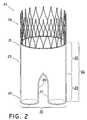
- FIG. 2shows the main body of the medical device.
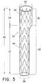
- FIG. 3shows a first extension graft of the medical device.
- FIG. 4shows a second extension graft of the medical device.
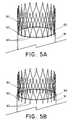
- FIGS. 5A and 5Bdepict an anchor sutured to the main graft proximal end.
- FIGS. 6A and 6Bdepict the first extension graft and second extension graft expanded within the main graft body.
- the present disclosureprovides for a medical device and method for bridging a defect in a main vessel near one or more branch vessels, for example at or in the vicinity of a bifurcation in the arterial system of a patient.
- the present disclosureis described below in reference to its application in connection with endovascular treatment of abdominal aortic aneurysms and dissections. However, it is likewise applicable to any suitable endovascular treatment or procedure including, without limitation, endovascular treatment of thoracic aortic aneurysms and dissections.
- Implantablerefers to an ability of a prosthetic implant to be positioned, for any duration of time, at a location within a body, such as within a body vessel.
- implantationand “implanted” refer to the positioning, for any duration of time, of a prosthetic implant at a location within a body, such as within a body vessel.
- Body vesselmeans any tube-shaped body passage lumen that conducts fluid, including but not limited to blood vessels such as those of the human vasculature system, esophageal, intestinal, billiary, urethral and ureteral passages.
- Brain vesselrefers to a vessel that branches off from a main vessel.
- the “branch vessels” of the thoracic and abdominal aortainclude the iliac, celiac, inferior phrenic, superior mesenteric, lumbar, inferior mesenteric, middle sacral, middle suprarenal, renal, internal spermatic, ovarian (in the female), innominate, left carotid, and left subclavian arteries.
- the hypogastric arteryis a branch vessel to the common iliac, which is a main vessel in this context.
- “Stent”means any device or structure that adds rigidity, expansion force, or support to a prosthesis.
- “Stent graft”refers to a prosthesis comprising a stent and a graft material associated therewith that forms a lumen through at least a portion of its length.
- Proximalmeans that position or portion of a component which is closest to the patient's heart.
- distalmeans that position of portion of a component which is furthest from the patient's heart.
- Biocompatiblerefers to a material that is substantially non-toxic in the in vivo environment of its intended use, and that is not substantially rejected by the patient's physiological system (i.e., is non-antigenic). This can be gauged by the ability of a material to pass the biocompatibility tests set forth in International Standards Organization (ISO) Standard No. 10993 and/or the U.S. Pharmacopeia (USP) 23 and/or the U.S. Food and Drug Administration (FDA) blue book memorandum No.
- ISOInternational Standards Organization
- USPU.S. Pharmacopeia
- FDAFood and Drug Administration
- G95-1entitled “Use of International Standard ISO-10993, Biological Evaluation of Medical Devices Part 1: Evaluation and Testing.” Typically, these tests measure a material's toxicity, infectivity, pyrogenicity, irritation potential, reactivity, hemolytic activity, carcinogenicity and/or immunogenicity.
- a biocompatible structure or materialwhen introduced into a majority of patients, will not cause a significantly adverse, long-lived or escalating biological reaction or response, and is distinguished from a mild, transient inflammation which typically accompanies surgery or implantation of foreign objects into a living organism.
- an inextensible materialmay have a stretch ratio not greater than 1.1. Stretch ratio is defined as the ratio of a material's deformed length to undeformed (e.g., no strain) length.
- Medical devicesmay be any device that is introduced temporarily or permanently into the body for the prophylaxis or therapy of a medical condition, for example abdominal aortic aneurysms.
- Typical subjectsalso referred to herein as “patients” are vertebrate subjects (i.e., members of the subphylum cordata), including, mammals such as cattle, sheep, pigs, goats, horses, dogs, cats and humans.
- FIG. 1depicts an exemplary medical device.
- Medical device 10may be positioned within a body vessel, such as a patient's aorta, to reinforce a weak spot or lesion in the body vessel at or near an aneurysm.
- the medical device 10is positioned within the body vessel at or in the vicinity of a bifurcation for example where the aorta meets the right and left common iliac arteries.
- the medical device 10may provide strength to the injured or diseased body vessel at the aneurysm and may allow fluid to flow through the medical device 10 without further stress and/or trauma to the aneurysm, thus preventing enlargement and/or rupture of the body vessel at the lesion site.
- the medical device 10may be used for the treatment of a dissection.
- the medical devicecomprises a main graft 11 , a first extension graft 12 , and a second extension graft 13 .
- the first and second extensions 12 , 13each include a proximal body portion 14 and a distal leg portion 15 .
- the proximal body portion 14 of the first extension graft 12 , second extension graft 13 , and a part of the distal leg portions 15may be located within and overlap with the main graft 11 .
- the main graft 11 , first extension graft 12 , and second extension graft 13may have any suitable length corresponding to a length of the lesion site at which the medical device is to be positioned.
- the medical device 10may be anchored to an interior wall surface of a body vessel proximally and/or distally to a lesion site.
- the main graft 11may be anchored to a main vessel wall proximal to an aneurysm and the first and second extension grafts 12 , 13 may be anchored distal to the aneurysm, for example to branch vessels.
- FIG. 2illustrates the main graft.
- the medical devicecomprises a main graft 20 .
- the main graftincludes a proximal end 21 , a distal end 22 , and a body 23 .
- the main graftmay have any suitable length 24 , but in one example the main graft may have a length 24 of about 2 inches, and the body may have a length 25 of about 1.5 inches.
- the main graft distal end 22has two branches 26 , 27 extending distally from the body 23 .
- the branches 26 , 27may be identical or differ.
- the branchesmay have the same or different lengths, the same or different widths, may be symmetrical or asymmetrical, or may comprise the same or different materials.
- the branches 26 , 27are of equal length and width.
- the main graft proximal end 21may include an anchor, such as a stent 28 .
- Suitable anchorsalso include any means for attaching a medical device to a body vessel wall, for example suturing, stapling, searing, bonding, gluing, bioadhesives, and the like.
- the anchormay be attached or adhered to the main graft by any means, including but not limited to welding, stitching, bonding, and adhesives.
- FIGS. 5A and 5Bdepict an exemplary anchor.
- the anchorcomprises a stent 80 attached to the graft 81 by sutures 82 to the main graft proximal end 83 .
- the stent 80may be spaced from the main graft proximal end 83 such that stent 80 does not overlap the main graft proximal end 83 .
- Sutures 82may space the stent 80 from the main graft proximal end 83 , permitting a reduced delivery profile for the main graft.
- FIG. 5Billustrates the stent 80 sutured to the main graft proximal end 83 and having an overlap with the main graft proximal end 83 .
- the medical device 10may comprise a first extension graft 12 and a second extension graft 13 .
- the extension grafts 50 , 60comprise a body reinforcing portion 51 , 61 and a branch reinforcing portion 52 , 62 .
- the extension graftsmay be identical or differ.
- the extension graftsmay have the same or different lengths, the same or differing widths, may be symmetrical or asymmetrical, or may comprise the same or differing materials.
- the extension grafts 50 , 60have a compressed and an expanded configuration.
- the extension grafts 50 , 60may radially expand from a compressed, or unexpanded, delivery configuration to one or more expanded deployment configurations.
- the extension grafts 50 , 60comprise stents 58 , 68 located about the body reinforcing portions 51 , 61 and stents 59 , 69 located about the branch reinforcing portions 52 , 62 .
- stents 58 , 68may be located on the interior, or luminal, surface of the body reinforcing portions 51 , 61 , respectively.
- Stents 59 , 69may be located on the exterior, or abluminal, surface of the branch reinforcing portions 52 , 62 .
- stents 59 , 69may be self-expanding and stents 58 , 68 may be balloon expandable. Upon compression, self-expanding stents may expand toward their pre-compression geometry.
- stents 59 , 69may be balloon expandable and/or stents 58 , 68 may be self-expanding.
- a balloonmay be used to urge the stents toward one another to provide optimal alignment of the extension grafts 50 , 60 .
- the body reinforcing portions 51 , 61may have an expanded diameter 53 , 63 that is at least as great as the expanded width or diameter 54 , 64 of the branch reinforcing portions 52 , 62 .
- the body reinforcing portions 51 , 61may have a combined width (e.g., width 53 plus width 63 ) that is at least as great as the diameter 30 of the main graft body 23 .
- the combined width or diameter of the body reinforcing portionsmay be generally equal to the main graft body width 30 .
- the extension grafts 50 , 60may have any suitable length 55 , 65 .
- the extension grafts 50 , 60may have a length 55 , 65 that is at least as great as the main graft length 24 .
- the extension graft length 55 , 65includes a body reinforcing portion length 56 , 66 and a branch reinforcing portion length 57 , 67 .
- the body reinforcing portion lengths 56 , 66may be equal to or less than the main graft body length 25 .
- the body reinforcing portions' lengths 56 , 66may be greater than the main graft body length 25 .
- the branch reinforcing portion lengths 67 , 77may be the same or different.
- the first extension graft 50has branch reinforcing portion length 57 that is greater than the branch reinforcing portion length 67 of the second extension graft 60 shown in FIG. 4 .
- the branch reinforcing portion lengths 57 , 67may be equal to or greater than the length 29 of the branches 26 , 27 extending distally from the main graft 20 .
- stents for use in connection with the present disclosuretypically comprise a plurality of apertures or open spaces between metallic filaments (including fibers and wires), segments or regions.
- Typical structuresinclude: an open-mesh network comprising one or more knitted, woven or braided metallic filaments; an interconnected network of articulable segments; a coiled or helical structure comprising one or more metallic filaments; and, a patterned tubular metallic sheet (e.g., a laser cut tube).
- the stentsmay be self-expanding or balloon-expandable, and may be deployed according to conventional methodology, such as by an inflatable balloon catheter, by a self-deployment mechanism (after release from a catheter), or by other appropriate means.
- the stentsmay be bifurcated, configured for any blood vessel including coronary arteries and peripheral arteries (e.g., renal, superficial femoral, carotid, and the like), a urethral stent, a biliary stent, a tracheal stent, a gastrointestinal stent, or an esophageal stent, for example.
- the stentsmay be any suitable vascular stent such as the commercially available Gianturco-Roubin FLEX-STENT® or SUPRA-G stents from Cook Incorporated (Bloomington, Ind.).
- the stent 80 depicted in FIGS. 3A and 3Bcomprises a modified chuter stent having eyelets.
- the stentsmay be made of one or more suitable biocompatible materials such as stainless steel, nitinol, MP35N, gold, tantalum, platinum or platinum irdium, niobium, tungsten, iconel, ceramic, nickel, titanium, stainless steel/titanium composite, cobalt, chromium, cobalt/chromium alloys, magnesium, aluminum, or other biocompatible metals and/or composites or alloys such as carbon or carbon fiber, cellulose acetate, cellulose nitrate, silicone, cross-linked polyvinyl alcohol (PVA) hydrogel, cross-linked PVA hydrogel foam, polyurethane, polyamide, styrene isobutylene-styrene block copolymer (Kraton), polyethylene teraphthalate, polyester, polyorthoester, polyanhydride, polyether sulfone, polycarbonate, polypropylene, high molecular weight polyethylene, polytetrafluoroethylene, or other biocompatible poly
- Stentsmay optionally include supplemental attachment means such as anchoring devices.
- supplemental attachment meanssuch as anchoring devices.
- the artprovides a wide variety of structural features that are acceptable for use in medical devices as anchoring devices, and any suitable structural feature can be used.
- individual barbsmay be used to implant the medical device into a vessel.
- the barbsmay be secured to the medical device by any means known to one skilled in the art, including but not limited to welding, stitching, bonding, and adhesives.
- barbscan also comprise separate members attached to the medical device by suitable attachment means.
- anchor 28may comprise features, such as barbs, that maintain the medical device in position following implantation in a body vessel.
- bioadhesivesmay be used for attachment.
- Bioadhesivemay be included in any suitable part of the prosthesis.
- the bioadhesiveis attached to the abluminal surface of the textile graft.
- Selection of the type of bioadhesive, the portions of the prosthesis comprising the bioadhesive, and the manner of attaching the bioadhesive to the prosthesiscan be chosen to perform a desired function upon implantation.
- the bioadhesivecan be selected to promote increased affinity of the desired portion of prosthesis to the section of the body vessel against which it is urged.
- Bioadhesives for use in conjunction with the present disclosureinclude any suitable bioadhesives known to those of ordinary skill in the art.
- appropriate bioadhesivesinclude, but are not limited to, the following: (1) cyanoacrylates such as ethyl cyanoacrylate, butyl cyanoacrylate, octyl cyanoacrylate, and hexyl cyanoacrylate; (2) fibrinogen, with or without thrombin, fibrin, fibropectin, elastin, and laminin; (3) mussel adhesive protein, chitosan, prolamine gel and transforming growth factor beta(TGF-B); (4) polysaccharides such as acacia, carboxymethyl-cellulose, dextran, hyaluronic acid, hydroxypropyl-cellulose, hydroxypropyl-methylcellulose, karaya gum, pectin, starch, alginates, and tragacanth; (5) polyacrylic acid, polycarbophil, modified
- bioadhesivesthat may be used in the present disclosure include, but are not limited to: FOCALSEAL® (biodegradable eosin-PEG-lactide hydrogel requiring photopolymerization with Xenon light wand) produced by Focal; BERIPLAST® produced by Adventis-Bering; VIVOSTAT® produced by ConvaTec (Bristol-Meyers-Squibb); SEALAGENTM produced by Baxter; FIBRX® (containing virally inactivated human fibrinogen and inhibited-human thrombin) produced by CryoLife; TISSEEL® (fibrin glue composed of plasma derivatives from the last stages in the natural coagulation pathway where soluble fibrinogen is converted into a solid fibrin) and TISSUCOL® produced by Baxter; QUIXIL® (Biological Active Component and Thrombin) produced by Omrix Biopharm; a PEG-collagen conjugate produced by Cohesion (Collagen); HY
- the main graft 11 and first and second extension grafts 12 , 13may include any suitable biocompatible material which is suitable for facilitating repair to the injured or diseased body vessel.
- the graft materialmay be synthetic, naturally-derived material, and/or manufactured.
- synthetic biocompatible polymersinclude, but are not limited, cellulose acetate, cellulose nitrate, silicone, polyethylene teraphthalate, polyurethane, polyamide, polyaramide, polyacrylonitrile, nylon, polyester, polyorthoester, polyanhydride, polyether sulfone, polycarbonate, polypropylene, high molecular weight polyethylene, polytetrafluoroethylene, or mixtures or copolymers thereof.
- the graft materialcomprises one or more polymers that do not require treatment or modification to be biocompatible.
- the graft materialmay comprise biocompatible polymers, such as polyethylene terephthalate and PTFE. These materials are inexpensive, easy to handle, have good physical characteristics and are suitable for clinical application. A commercial example of polyethylene terephthalate especially is Dacron.
- the main graft 20comprises an inextensible material, such as Dacron®.
- the main graft 11may reach its tailored full diameter 30 .
- the inextensible materialmay not permit the main graft 11 to expand further in size under internal loading, such as from blood pressure or stent loading.
- first extension graft 50 and second extension graft 60may comprise a hybrid material, for example a hybrid weave which is extensible at the body reinforcing portion 51 , 61 , such as spandex, and transitions to an inextensible fabric at the branch reinforcing portion 52 , 62 , such as Dacron®.
- a hybrid materialfor example a hybrid weave which is extensible at the body reinforcing portion 51 , 61 , such as spandex, and transitions to an inextensible fabric at the branch reinforcing portion 52 , 62 , such as Dacron®.
- a balloonmay be inserted into each extension graft 50 , 60 , either separately or in parallel (simultaneously), and when inflated the body reinforcing portions 51 , 61 may expand beyond their nominal diameter 53 , 63 and enhance the proximal seal, for example sealing the main graft body 23 to a vessel wall.
- the medical device 10maybe be configured for delivery to a body vessel.
- a medical devicemay be compressed to a delivery configuration within a retaining sheath that is part of a delivery system, such as a catheter-based system.
- the medical devicecan be expanded, for example, by use of self-expanding stents and/or inflating a balloon from inside the stents.
- the delivery configurationcan be maintained prior to deployment of the medical device by any suitable means, including a sheath, a suture, a tube or other restraining material around all or part of the compressed prosthesis, or other methods.
- Medical devicescan be deployed in a body vessel by means appropriate to their design. Medical devices of the present disclosure can be adapted for deployment using conventional methods known in the art and employing percutaneous transluminal catheter devices. The medical devices are designed for deployment by any of a variety of in situ expansion means.
- a medical devicemay be mounted onto a catheter that holds the medical device as it is delivered through the body lumen and then releases the medical device, permitting the medical device to expand and contact the body lumen.
- This deploymentis effected after the medical device has been introduced percutaneously, transported transluminally and positioned at a desired location by means of the catheter.
- the medical devicemay be positioned at the distal end of a catheter with a removable sheath or sleeve placed over the medical device to hold the medical device in a compressed delivery configuration with a relatively small diameter.
- the medical devicemay then be implanted at the point of treatment by advancing the catheter over a guide wire to the location of the lesion, aligning the medical device with any branch vessels, and then withdrawing the sheath from over the medical device.
- the medical devicemay expand and seal against the wall of the blood vessel at the site of treatment.
- the catheter, sleeve, and guide wiremay then be removed from the patient.
- the main graft 20may be delivered endovascularly to a lesion site in a compressed, or unexpanded, delivery configuration.
- a compressed main graftmay be delivered via a 9 Fr to about 14 Fr sheath to a location immediately distal the renal arteries.
- the sheathmay be withdrawn, deploying the main graft 20 .
- the main graft 20may be held in place at the treatment location by anchor 28 at the delivery location.
- the main graftmay expand due to blood flow through the main graft 20 , similar to a wind sock effect.
- the first extension graft 50 and second extension graft 60may be delivered endovascularly to the treatment location.
- the first extension graft 50may be compressed to a delivery configuration in a sheath and delivered to a location near the main graft proximal end 21 .
- the sheathmay be withdrawn allowing the first extension graft 50 to expand.
- the first branch 26may be cannulated prior to delivery of the first extension graft 50 .
- the second extension graft 60may be compressed to a delivery configuration in a sheath and delivered to a location near the main graft proximal end 21 . Upon locating the second extension graft 60 , the sheath may be withdrawn allowing the second extension graft 60 to expand. In one example, the second branch 27 may be cannulated via an up-and-over guide catheter prior to delivery of the second extension graft 60 .
- first extension graft 50 and second extension graft 60may expand in the main graft.
- branch reinforcing portion 52may expand and seal the first extension graft 50 in the main graft first branch 26 and the second branch reinforcing portion 62 may expand and seal the extension graft 60 in the main graft second branch 27 .
- the first extension graft body reinforcing portion 51 and second extension graft body reinforcing portion 61may expand within the main graft body 23 .
- the body reinforcing portions 51 , 61may interact with one another to provide sealing forces about the main graft 20 .
- the first extension graft body reinforcing portion 91interferes with the second extension graft body reinforcing portion 92 within the main graft 90 .
- FIG. 6Adepicts the first extension graft body reinforcing portion 91 and the second extension graft body reinforcing portion 92 having a D-shaped radial contour within the main graft 90 .
- the first extension graft body reinforcing portion 91 and the second extension graft body reinforcing portion 92may expand asymmetrically in the main graft 90 , as depicted in FIG. 6B .
- a balloonmay be used to position the body reinforcing portions to provide optimal alignment of the body reinforcing portions 91 , 92 .
- Any voids 93 within with main graftmay fill with fluid and, in one example, the fluid may clot and prevent any possible fluid leakage.
Landscapes
- Health & Medical Sciences (AREA)
- Heart & Thoracic Surgery (AREA)
- Life Sciences & Earth Sciences (AREA)
- Cardiology (AREA)
- Oral & Maxillofacial Surgery (AREA)
- Transplantation (AREA)
- Engineering & Computer Science (AREA)
- Pulmonology (AREA)
- Biomedical Technology (AREA)
- Vascular Medicine (AREA)
- Gastroenterology & Hepatology (AREA)
- Animal Behavior & Ethology (AREA)
- General Health & Medical Sciences (AREA)
- Public Health (AREA)
- Veterinary Medicine (AREA)
- Prostheses (AREA)
- Materials For Medical Uses (AREA)
Abstract
Description
Claims (21)
Priority Applications (1)
| Application Number | Priority Date | Filing Date | Title |
|---|---|---|---|
| US12/337,452US8021413B2 (en) | 2007-12-27 | 2008-12-17 | Low profile medical device |
Applications Claiming Priority (2)
| Application Number | Priority Date | Filing Date | Title |
|---|---|---|---|
| US1694207P | 2007-12-27 | 2007-12-27 | |
| US12/337,452US8021413B2 (en) | 2007-12-27 | 2008-12-17 | Low profile medical device |
Publications (2)
| Publication Number | Publication Date |
|---|---|
| US20090177265A1 US20090177265A1 (en) | 2009-07-09 |
| US8021413B2true US8021413B2 (en) | 2011-09-20 |
Family
ID=40568413
Family Applications (1)
| Application Number | Title | Priority Date | Filing Date |
|---|---|---|---|
| US12/337,452Active2029-01-02US8021413B2 (en) | 2007-12-27 | 2008-12-17 | Low profile medical device |
Country Status (6)
| Country | Link |
|---|---|
| US (1) | US8021413B2 (en) |
| EP (1) | EP2229124B1 (en) |
| JP (1) | JP5458324B2 (en) |
| CN (2) | CN104586538B (en) |
| AU (1) | AU2008343933B2 (en) |
| WO (1) | WO2009085186A1 (en) |
Cited By (87)
| Publication number | Priority date | Publication date | Assignee | Title |
|---|---|---|---|---|
| US20140005764A1 (en)* | 2012-06-30 | 2014-01-02 | Cordis Corporation | Sealing mechanism for expandable vascular device |
| US8702791B2 (en) | 2012-04-12 | 2014-04-22 | Sanford Health | Debranching visceral stent graft and methods for use |
| US8880185B2 (en) | 2010-06-11 | 2014-11-04 | Boston Scientific Scimed, Inc. | Renal denervation and stimulation employing wireless vascular energy transfer arrangement |
| US8939970B2 (en) | 2004-09-10 | 2015-01-27 | Vessix Vascular, Inc. | Tuned RF energy and electrical tissue characterization for selective treatment of target tissues |
| US8951251B2 (en) | 2011-11-08 | 2015-02-10 | Boston Scientific Scimed, Inc. | Ostial renal nerve ablation |
| US8974451B2 (en) | 2010-10-25 | 2015-03-10 | Boston Scientific Scimed, Inc. | Renal nerve ablation using conductive fluid jet and RF energy |
| US9023034B2 (en) | 2010-11-22 | 2015-05-05 | Boston Scientific Scimed, Inc. | Renal ablation electrode with force-activatable conduction apparatus |
| US9028472B2 (en) | 2011-12-23 | 2015-05-12 | Vessix Vascular, Inc. | Methods and apparatuses for remodeling tissue of or adjacent to a body passage |
| US9028485B2 (en) | 2010-11-15 | 2015-05-12 | Boston Scientific Scimed, Inc. | Self-expanding cooling electrode for renal nerve ablation |
| US9050106B2 (en) | 2011-12-29 | 2015-06-09 | Boston Scientific Scimed, Inc. | Off-wall electrode device and methods for nerve modulation |
| US9060761B2 (en) | 2010-11-18 | 2015-06-23 | Boston Scientific Scime, Inc. | Catheter-focused magnetic field induced renal nerve ablation |
| US9079000B2 (en) | 2011-10-18 | 2015-07-14 | Boston Scientific Scimed, Inc. | Integrated crossing balloon catheter |
| US9084609B2 (en) | 2010-07-30 | 2015-07-21 | Boston Scientific Scime, Inc. | Spiral balloon catheter for renal nerve ablation |
| US9089350B2 (en) | 2010-11-16 | 2015-07-28 | Boston Scientific Scimed, Inc. | Renal denervation catheter with RF electrode and integral contrast dye injection arrangement |
| US9119632B2 (en) | 2011-11-21 | 2015-09-01 | Boston Scientific Scimed, Inc. | Deflectable renal nerve ablation catheter |
| US9119600B2 (en) | 2011-11-15 | 2015-09-01 | Boston Scientific Scimed, Inc. | Device and methods for renal nerve modulation monitoring |
| US9125666B2 (en) | 2003-09-12 | 2015-09-08 | Vessix Vascular, Inc. | Selectable eccentric remodeling and/or ablation of atherosclerotic material |
| US9125667B2 (en) | 2004-09-10 | 2015-09-08 | Vessix Vascular, Inc. | System for inducing desirable temperature effects on body tissue |
| US9155589B2 (en) | 2010-07-30 | 2015-10-13 | Boston Scientific Scimed, Inc. | Sequential activation RF electrode set for renal nerve ablation |
| US9162046B2 (en) | 2011-10-18 | 2015-10-20 | Boston Scientific Scimed, Inc. | Deflectable medical devices |
| US9173696B2 (en) | 2012-09-17 | 2015-11-03 | Boston Scientific Scimed, Inc. | Self-positioning electrode system and method for renal nerve modulation |
| US9186209B2 (en) | 2011-07-22 | 2015-11-17 | Boston Scientific Scimed, Inc. | Nerve modulation system having helical guide |
| US9186210B2 (en) | 2011-10-10 | 2015-11-17 | Boston Scientific Scimed, Inc. | Medical devices including ablation electrodes |
| US9192435B2 (en) | 2010-11-22 | 2015-11-24 | Boston Scientific Scimed, Inc. | Renal denervation catheter with cooled RF electrode |
| US9192790B2 (en) | 2010-04-14 | 2015-11-24 | Boston Scientific Scimed, Inc. | Focused ultrasonic renal denervation |
| US9220561B2 (en) | 2011-01-19 | 2015-12-29 | Boston Scientific Scimed, Inc. | Guide-compatible large-electrode catheter for renal nerve ablation with reduced arterial injury |
| US9220558B2 (en) | 2010-10-27 | 2015-12-29 | Boston Scientific Scimed, Inc. | RF renal denervation catheter with multiple independent electrodes |
| US9265969B2 (en) | 2011-12-21 | 2016-02-23 | Cardiac Pacemakers, Inc. | Methods for modulating cell function |
| US9277955B2 (en) | 2010-04-09 | 2016-03-08 | Vessix Vascular, Inc. | Power generating and control apparatus for the treatment of tissue |
| US9297845B2 (en) | 2013-03-15 | 2016-03-29 | Boston Scientific Scimed, Inc. | Medical devices and methods for treatment of hypertension that utilize impedance compensation |
| US9326751B2 (en) | 2010-11-17 | 2016-05-03 | Boston Scientific Scimed, Inc. | Catheter guidance of external energy for renal denervation |
| US9327100B2 (en) | 2008-11-14 | 2016-05-03 | Vessix Vascular, Inc. | Selective drug delivery in a lumen |
| US9358365B2 (en) | 2010-07-30 | 2016-06-07 | Boston Scientific Scimed, Inc. | Precision electrode movement control for renal nerve ablation |
| US9364284B2 (en) | 2011-10-12 | 2016-06-14 | Boston Scientific Scimed, Inc. | Method of making an off-wall spacer cage |
| US9408661B2 (en) | 2010-07-30 | 2016-08-09 | Patrick A. Haverkost | RF electrodes on multiple flexible wires for renal nerve ablation |
| US9420955B2 (en) | 2011-10-11 | 2016-08-23 | Boston Scientific Scimed, Inc. | Intravascular temperature monitoring system and method |
| US9433760B2 (en) | 2011-12-28 | 2016-09-06 | Boston Scientific Scimed, Inc. | Device and methods for nerve modulation using a novel ablation catheter with polymeric ablative elements |
| US9463062B2 (en) | 2010-07-30 | 2016-10-11 | Boston Scientific Scimed, Inc. | Cooled conductive balloon RF catheter for renal nerve ablation |
| US9486355B2 (en) | 2005-05-03 | 2016-11-08 | Vessix Vascular, Inc. | Selective accumulation of energy with or without knowledge of tissue topography |
| US9579030B2 (en) | 2011-07-20 | 2017-02-28 | Boston Scientific Scimed, Inc. | Percutaneous devices and methods to visualize, target and ablate nerves |
| US9649156B2 (en) | 2010-12-15 | 2017-05-16 | Boston Scientific Scimed, Inc. | Bipolar off-wall electrode device for renal nerve ablation |
| US9668811B2 (en) | 2010-11-16 | 2017-06-06 | Boston Scientific Scimed, Inc. | Minimally invasive access for renal nerve ablation |
| US9687166B2 (en) | 2013-10-14 | 2017-06-27 | Boston Scientific Scimed, Inc. | High resolution cardiac mapping electrode array catheter |
| US9693821B2 (en) | 2013-03-11 | 2017-07-04 | Boston Scientific Scimed, Inc. | Medical devices for modulating nerves |
| US9707036B2 (en) | 2013-06-25 | 2017-07-18 | Boston Scientific Scimed, Inc. | Devices and methods for nerve modulation using localized indifferent electrodes |
| US9713730B2 (en) | 2004-09-10 | 2017-07-25 | Boston Scientific Scimed, Inc. | Apparatus and method for treatment of in-stent restenosis |
| US9757193B2 (en) | 2002-04-08 | 2017-09-12 | Medtronic Ardian Luxembourg S.A.R.L. | Balloon catheter apparatus for renal neuromodulation |
| US9770606B2 (en) | 2013-10-15 | 2017-09-26 | Boston Scientific Scimed, Inc. | Ultrasound ablation catheter with cooling infusion and centering basket |
| US9808311B2 (en) | 2013-03-13 | 2017-11-07 | Boston Scientific Scimed, Inc. | Deflectable medical devices |
| US9808300B2 (en) | 2006-05-02 | 2017-11-07 | Boston Scientific Scimed, Inc. | Control of arterial smooth muscle tone |
| US9827039B2 (en) | 2013-03-15 | 2017-11-28 | Boston Scientific Scimed, Inc. | Methods and apparatuses for remodeling tissue of or adjacent to a body passage |
| US9827040B2 (en) | 2002-04-08 | 2017-11-28 | Medtronic Adrian Luxembourg S.a.r.l. | Methods and apparatus for intravascularly-induced neuromodulation |
| US9833283B2 (en) | 2013-07-01 | 2017-12-05 | Boston Scientific Scimed, Inc. | Medical devices for renal nerve ablation |
| US9895194B2 (en) | 2013-09-04 | 2018-02-20 | Boston Scientific Scimed, Inc. | Radio frequency (RF) balloon catheter having flushing and cooling capability |
| US9907609B2 (en) | 2014-02-04 | 2018-03-06 | Boston Scientific Scimed, Inc. | Alternative placement of thermal sensors on bipolar electrode |
| US9919144B2 (en) | 2011-04-08 | 2018-03-20 | Medtronic Adrian Luxembourg S.a.r.l. | Iontophoresis drug delivery system and method for denervation of the renal sympathetic nerve and iontophoretic drug delivery |
| US9925001B2 (en) | 2013-07-19 | 2018-03-27 | Boston Scientific Scimed, Inc. | Spiral bipolar electrode renal denervation balloon |
| US9943365B2 (en) | 2013-06-21 | 2018-04-17 | Boston Scientific Scimed, Inc. | Renal denervation balloon catheter with ride along electrode support |
| US9949818B2 (en) | 2012-12-14 | 2018-04-24 | Sanford Health | Combination double-barreled and debranching stent grafts and methods for use |
| US9956033B2 (en) | 2013-03-11 | 2018-05-01 | Boston Scientific Scimed, Inc. | Medical devices for modulating nerves |
| US9962223B2 (en) | 2013-10-15 | 2018-05-08 | Boston Scientific Scimed, Inc. | Medical device balloon |
| US9974607B2 (en) | 2006-10-18 | 2018-05-22 | Vessix Vascular, Inc. | Inducing desirable temperature effects on body tissue |
| US9987122B2 (en) | 2016-04-13 | 2018-06-05 | Medtronic Vascular, Inc. | Iliac branch device and method |
| US10022182B2 (en) | 2013-06-21 | 2018-07-17 | Boston Scientific Scimed, Inc. | Medical devices for renal nerve ablation having rotatable shafts |
| US10085799B2 (en) | 2011-10-11 | 2018-10-02 | Boston Scientific Scimed, Inc. | Off-wall electrode device and methods for nerve modulation |
| US10265122B2 (en) | 2013-03-15 | 2019-04-23 | Boston Scientific Scimed, Inc. | Nerve ablation devices and related methods of use |
| US10271898B2 (en) | 2013-10-25 | 2019-04-30 | Boston Scientific Scimed, Inc. | Embedded thermocouple in denervation flex circuit |
| US10321946B2 (en) | 2012-08-24 | 2019-06-18 | Boston Scientific Scimed, Inc. | Renal nerve modulation devices with weeping RF ablation balloons |
| US10342609B2 (en) | 2013-07-22 | 2019-07-09 | Boston Scientific Scimed, Inc. | Medical devices for renal nerve ablation |
| US10357353B2 (en) | 2012-04-12 | 2019-07-23 | Sanford Health | Combination double-barreled and debranching stent grafts and methods for use |
| US10398464B2 (en) | 2012-09-21 | 2019-09-03 | Boston Scientific Scimed, Inc. | System for nerve modulation and innocuous thermal gradient nerve block |
| US10413357B2 (en) | 2013-07-11 | 2019-09-17 | Boston Scientific Scimed, Inc. | Medical device with stretchable electrode assemblies |
| US10470871B2 (en) | 2001-12-20 | 2019-11-12 | Trivascular, Inc. | Advanced endovascular graft |
| US10549127B2 (en) | 2012-09-21 | 2020-02-04 | Boston Scientific Scimed, Inc. | Self-cooling ultrasound ablation catheter |
| US10588682B2 (en) | 2011-04-25 | 2020-03-17 | Medtronic Ardian Luxembourg S.A.R.L. | Apparatus and methods related to constrained deployment of cryogenic balloons for limited cryogenic ablation of vessel walls |
| US10660698B2 (en) | 2013-07-11 | 2020-05-26 | Boston Scientific Scimed, Inc. | Devices and methods for nerve modulation |
| US10660703B2 (en) | 2012-05-08 | 2020-05-26 | Boston Scientific Scimed, Inc. | Renal nerve modulation devices |
| US10695124B2 (en) | 2013-07-22 | 2020-06-30 | Boston Scientific Scimed, Inc. | Renal nerve ablation catheter having twist balloon |
| US10709490B2 (en) | 2014-05-07 | 2020-07-14 | Medtronic Ardian Luxembourg S.A.R.L. | Catheter assemblies comprising a direct heating element for renal neuromodulation and associated systems and methods |
| US10722300B2 (en) | 2013-08-22 | 2020-07-28 | Boston Scientific Scimed, Inc. | Flexible circuit having improved adhesion to a renal nerve modulation balloon |
| US10835305B2 (en) | 2012-10-10 | 2020-11-17 | Boston Scientific Scimed, Inc. | Renal nerve modulation devices and methods |
| US10888414B2 (en) | 2019-03-20 | 2021-01-12 | inQB8 Medical Technologies, LLC | Aortic dissection implant |
| US10945786B2 (en) | 2013-10-18 | 2021-03-16 | Boston Scientific Scimed, Inc. | Balloon catheters with flexible conducting wires and related methods of use and manufacture |
| US10952790B2 (en) | 2013-09-13 | 2021-03-23 | Boston Scientific Scimed, Inc. | Ablation balloon with vapor deposited cover layer |
| US11000679B2 (en) | 2014-02-04 | 2021-05-11 | Boston Scientific Scimed, Inc. | Balloon protection and rewrapping devices and related methods of use |
| US11202671B2 (en) | 2014-01-06 | 2021-12-21 | Boston Scientific Scimed, Inc. | Tear resistant flex circuit assembly |
| US11246654B2 (en) | 2013-10-14 | 2022-02-15 | Boston Scientific Scimed, Inc. | Flexible renal nerve ablation devices and related methods of use and manufacture |
Families Citing this family (20)
| Publication number | Priority date | Publication date | Assignee | Title |
|---|---|---|---|---|
| WO2011008989A2 (en) | 2009-07-15 | 2011-01-20 | Endologix, Inc. | Stent graft |
| EP2506799A4 (en)* | 2009-12-01 | 2014-10-29 | Altura Medical Inc | Modular endograft devices and associated systems and methods |
| JP4991014B2 (en) | 2010-07-07 | 2012-08-01 | 日機装株式会社 | Artificial blood vessel |
| US20120029611A1 (en)* | 2010-07-28 | 2012-02-02 | Medtronic Vascular, Inc. | Stent Graft System and Method of Use |
| WO2012040240A1 (en) | 2010-09-20 | 2012-03-29 | Altura Medical, Inc. | Stent graft delivery systems and associated methods |
| US9155612B2 (en)* | 2011-01-10 | 2015-10-13 | Intermountain Invention Management, Llc | Composite stent grafts for in situ assembly and related methods |
| US10154894B2 (en)* | 2011-10-18 | 2018-12-18 | David J. Minion | Endografts for parallel endoluminal grafts |
| DE102012100754A1 (en)* | 2012-01-31 | 2013-08-01 | Jotec Gmbh | Modular stent graft |
| CA2881535A1 (en) | 2012-08-10 | 2014-02-13 | Altura Medical, Inc. | Stent delivery systems and associated methods |
| DE102012110861A1 (en)* | 2012-11-12 | 2014-05-15 | Georg-August-Universität Göttingen Stiftung Öffentlichen Rechts Bereich Universitätsmedizin | Endovascular stent graft, stent and stent-in-stent system |
| WO2014144809A1 (en) | 2013-03-15 | 2014-09-18 | Altura Medical, Inc. | Endograft device delivery systems and associated methods |
| WO2015061669A1 (en)* | 2013-10-24 | 2015-04-30 | The Cleveland Clinic Foundation | Branched vessel prosthesis for repair of a failed stent graft |
| CN108403257B (en)* | 2014-05-30 | 2021-03-16 | 安德乐吉克斯有限责任公司 | Modular stent graft system and method using inflatable fill structures |
| WO2017222875A1 (en)* | 2016-06-21 | 2017-12-28 | Medtronic Vascular Inc. | Coated endovascular prostheses for aneurism treatment |
| US20200281711A1 (en)* | 2017-02-01 | 2020-09-10 | Endologix, Inc. | Longitudinally extendable stent graft systems and methods |
| DE102017123461A1 (en)* | 2017-10-10 | 2019-04-11 | Jotec Gmbh | Expandable vascular implant |
| CN109833115B (en)* | 2017-11-24 | 2025-07-11 | 杭州唯强医疗科技有限公司 | Multi-lumen covered stent |
| CN109833123B (en) | 2017-11-24 | 2021-04-20 | 杭州唯强医疗科技有限公司 | Vascular shunt and vascular stent with improved adherence |
| WO2021223622A1 (en)* | 2020-05-06 | 2021-11-11 | 杭州唯强医疗科技有限公司 | Vascular split-flow stent and vascular stent |
| US11324583B1 (en) | 2021-07-06 | 2022-05-10 | Archo Medical LTDA | Multi-lumen stent-graft and related surgical methods |
Citations (31)
| Publication number | Priority date | Publication date | Assignee | Title |
|---|---|---|---|---|
| EP0461791A1 (en) | 1990-06-11 | 1991-12-18 | Hector D. Barone | Aortic graft and apparatus for repairing an abdominal aortic aneurysm |
| US5282484A (en) | 1989-08-18 | 1994-02-01 | Endovascular Instruments, Inc. | Method for performing a partial atherectomy |
| US5571170A (en) | 1992-01-08 | 1996-11-05 | Expandable Grafts Partnership | Method and apparatus for bilateral intra-aortic bypass |
| US5676696A (en) | 1995-02-24 | 1997-10-14 | Intervascular, Inc. | Modular bifurcated intraluminal grafts and methods for delivering and assembling same |
| US5716365A (en) | 1994-02-09 | 1998-02-10 | Boston Scientific Technologies, Inc. | Bifurcated endoluminal prosthesis |
| US5723004A (en) | 1993-10-21 | 1998-03-03 | Corvita Corporation | Expandable supportive endoluminal grafts |
| US5728131A (en) | 1995-06-12 | 1998-03-17 | Endotex Interventional Systems, Inc. | Coupling device and method of use |
| US5782904A (en) | 1993-09-30 | 1998-07-21 | Endogad Research Pty Limited | Intraluminal graft |
| WO1998044873A1 (en) | 1997-04-10 | 1998-10-15 | William Cook, Europe A/S | Endovascular graft for repairing abdominal aortic aneurysms |
| US5824037A (en) | 1995-10-03 | 1998-10-20 | Medtronic, Inc. | Modular intraluminal prostheses construction and methods |
| US5824040A (en) | 1995-12-01 | 1998-10-20 | Medtronic, Inc. | Endoluminal prostheses and therapies for highly variable body lumens |
| US5843158A (en) | 1996-01-05 | 1998-12-01 | Medtronic, Inc. | Limited expansion endoluminal prostheses and methods for their use |
| US6099558A (en) | 1995-10-10 | 2000-08-08 | Edwards Lifesciences Corp. | Intraluminal grafting of a bifuricated artery |
| US6129756A (en) | 1998-03-16 | 2000-10-10 | Teramed, Inc. | Biluminal endovascular graft system |
| US6162246A (en) | 1999-02-16 | 2000-12-19 | Barone; Hector Daniel | Aortic graft and method of treating abdominal aortic aneurysms |
| US6293969B1 (en) | 1997-01-29 | 2001-09-25 | Endovascular Technologies, Inc. | Bell-bottom modular stent-graft |
| US6334869B1 (en) | 1995-10-30 | 2002-01-01 | World Medical Manufacturing Corporation | Endoluminal prosthesis |
| US6383171B1 (en) | 1999-10-12 | 2002-05-07 | Allan Will | Methods and devices for protecting a passageway in a body when advancing devices through the passageway |
| US6409756B1 (en) | 2000-01-24 | 2002-06-25 | Edward G. Murphy | Endovascular aortic graft |
| US6451053B1 (en) | 1998-09-30 | 2002-09-17 | Edwards Lifesciences, Corp. | Methods and apparatus for intraluminal placement of a bifurcated intraluminal graft |
| US6478813B1 (en)* | 1997-08-01 | 2002-11-12 | Peter T. Keith | Method for joining grafts in a common body passageway |
| US6592614B2 (en) | 1996-01-05 | 2003-07-15 | Medtronic Ave, Inc. | Cuffed endoluminal prosthesis |
| US6695875B2 (en) | 2000-03-14 | 2004-02-24 | Cook Incorporated | Endovascular stent graft |
| US6730119B1 (en) | 2000-10-06 | 2004-05-04 | Board Of Regents Of The University Of Texas System | Percutaneous implantation of partially covered stents in aneurysmally dilated arterial segments with subsequent embolization and obliteration of the aneurysm cavity |
| US20050043784A1 (en) | 2003-08-20 | 2005-02-24 | Ilya Yampolsky | Stent with improved resistance to migration |
| WO2005032340A2 (en) | 2003-09-29 | 2005-04-14 | Secant Medical, Llc | Integral support stent graft assembly |
| US6918926B2 (en) | 2002-04-25 | 2005-07-19 | Medtronic Vascular, Inc. | System for transrenal/intraostial fixation of endovascular prosthesis |
| US6942691B1 (en) | 2000-04-27 | 2005-09-13 | Timothy A. M. Chuter | Modular bifurcated graft for endovascular aneurysm repair |
| US20060100686A1 (en) | 2001-11-28 | 2006-05-11 | Aptus Endosystems, Inc. | Devices, systems, and methods for prosthesis delivery and implantation |
| US7135037B1 (en) | 2000-05-01 | 2006-11-14 | Endovascular Technologies, Inc. | System and method for forming a junction between elements of a modular endovascular prosthesis |
| US20070055345A1 (en) | 2005-09-02 | 2007-03-08 | Medtronic Vascular, Inc. | Endoluminal prosthesis |
Family Cites Families (1)
| Publication number | Priority date | Publication date | Assignee | Title |
|---|---|---|---|---|
| US20060224232A1 (en)* | 2005-04-01 | 2006-10-05 | Trivascular, Inc. | Hybrid modular endovascular graft |
- 2008
- 2008-12-17USUS12/337,452patent/US8021413B2/enactiveActive
- 2008-12-18EPEP08868379.2Apatent/EP2229124B1/enactiveActive
- 2008-12-18WOPCT/US2008/013850patent/WO2009085186A1/enactiveApplication Filing
- 2008-12-18CNCN201510023330.7Apatent/CN104586538B/enactiveActive
- 2008-12-18CNCN2008801225537Apatent/CN101917931A/enactivePending
- 2008-12-18JPJP2010540648Apatent/JP5458324B2/ennot_activeExpired - Fee Related
- 2008-12-18AUAU2008343933Apatent/AU2008343933B2/ennot_activeCeased
Patent Citations (32)
| Publication number | Priority date | Publication date | Assignee | Title |
|---|---|---|---|---|
| US5282484A (en) | 1989-08-18 | 1994-02-01 | Endovascular Instruments, Inc. | Method for performing a partial atherectomy |
| EP0461791A1 (en) | 1990-06-11 | 1991-12-18 | Hector D. Barone | Aortic graft and apparatus for repairing an abdominal aortic aneurysm |
| US5571170A (en) | 1992-01-08 | 1996-11-05 | Expandable Grafts Partnership | Method and apparatus for bilateral intra-aortic bypass |
| US5782904A (en) | 1993-09-30 | 1998-07-21 | Endogad Research Pty Limited | Intraluminal graft |
| US5723004A (en) | 1993-10-21 | 1998-03-03 | Corvita Corporation | Expandable supportive endoluminal grafts |
| US5716365A (en) | 1994-02-09 | 1998-02-10 | Boston Scientific Technologies, Inc. | Bifurcated endoluminal prosthesis |
| US5676696A (en) | 1995-02-24 | 1997-10-14 | Intervascular, Inc. | Modular bifurcated intraluminal grafts and methods for delivering and assembling same |
| US5728131A (en) | 1995-06-12 | 1998-03-17 | Endotex Interventional Systems, Inc. | Coupling device and method of use |
| US5824037A (en) | 1995-10-03 | 1998-10-20 | Medtronic, Inc. | Modular intraluminal prostheses construction and methods |
| US6099558A (en) | 1995-10-10 | 2000-08-08 | Edwards Lifesciences Corp. | Intraluminal grafting of a bifuricated artery |
| US6334869B1 (en) | 1995-10-30 | 2002-01-01 | World Medical Manufacturing Corporation | Endoluminal prosthesis |
| US5824040A (en) | 1995-12-01 | 1998-10-20 | Medtronic, Inc. | Endoluminal prostheses and therapies for highly variable body lumens |
| US5843158A (en) | 1996-01-05 | 1998-12-01 | Medtronic, Inc. | Limited expansion endoluminal prostheses and methods for their use |
| US6592614B2 (en) | 1996-01-05 | 2003-07-15 | Medtronic Ave, Inc. | Cuffed endoluminal prosthesis |
| US6293969B1 (en) | 1997-01-29 | 2001-09-25 | Endovascular Technologies, Inc. | Bell-bottom modular stent-graft |
| WO1998044873A1 (en) | 1997-04-10 | 1998-10-15 | William Cook, Europe A/S | Endovascular graft for repairing abdominal aortic aneurysms |
| US6478813B1 (en)* | 1997-08-01 | 2002-11-12 | Peter T. Keith | Method for joining grafts in a common body passageway |
| US6129756A (en) | 1998-03-16 | 2000-10-10 | Teramed, Inc. | Biluminal endovascular graft system |
| US6451053B1 (en) | 1998-09-30 | 2002-09-17 | Edwards Lifesciences, Corp. | Methods and apparatus for intraluminal placement of a bifurcated intraluminal graft |
| US6162246A (en) | 1999-02-16 | 2000-12-19 | Barone; Hector Daniel | Aortic graft and method of treating abdominal aortic aneurysms |
| US6383171B1 (en) | 1999-10-12 | 2002-05-07 | Allan Will | Methods and devices for protecting a passageway in a body when advancing devices through the passageway |
| US6409756B1 (en) | 2000-01-24 | 2002-06-25 | Edward G. Murphy | Endovascular aortic graft |
| US6695875B2 (en) | 2000-03-14 | 2004-02-24 | Cook Incorporated | Endovascular stent graft |
| US6942691B1 (en) | 2000-04-27 | 2005-09-13 | Timothy A. M. Chuter | Modular bifurcated graft for endovascular aneurysm repair |
| US7135037B1 (en) | 2000-05-01 | 2006-11-14 | Endovascular Technologies, Inc. | System and method for forming a junction between elements of a modular endovascular prosthesis |
| US6730119B1 (en) | 2000-10-06 | 2004-05-04 | Board Of Regents Of The University Of Texas System | Percutaneous implantation of partially covered stents in aneurysmally dilated arterial segments with subsequent embolization and obliteration of the aneurysm cavity |
| US20060100686A1 (en) | 2001-11-28 | 2006-05-11 | Aptus Endosystems, Inc. | Devices, systems, and methods for prosthesis delivery and implantation |
| US6918926B2 (en) | 2002-04-25 | 2005-07-19 | Medtronic Vascular, Inc. | System for transrenal/intraostial fixation of endovascular prosthesis |
| US20050043784A1 (en) | 2003-08-20 | 2005-02-24 | Ilya Yampolsky | Stent with improved resistance to migration |
| WO2005032340A2 (en) | 2003-09-29 | 2005-04-14 | Secant Medical, Llc | Integral support stent graft assembly |
| US7122052B2 (en) | 2003-09-29 | 2006-10-17 | Stout Medical Group Lp | Integral support stent graft assembly |
| US20070055345A1 (en) | 2005-09-02 | 2007-03-08 | Medtronic Vascular, Inc. | Endoluminal prosthesis |
Non-Patent Citations (2)
| Title |
|---|
| PCT International Search Report for PCT/US2008/013850, May 8, 2009. |
| PCT Written Opinion for PCT/US2008/013850, May 8, 2009. |
Cited By (117)
| Publication number | Priority date | Publication date | Assignee | Title |
|---|---|---|---|---|
| US11439497B2 (en) | 2001-12-20 | 2022-09-13 | Trivascular, Inc. | Advanced endovascular graft |
| US10470871B2 (en) | 2001-12-20 | 2019-11-12 | Trivascular, Inc. | Advanced endovascular graft |
| US10105180B2 (en) | 2002-04-08 | 2018-10-23 | Medtronic Ardian Luxembourg S.A.R.L. | Methods and apparatus for intravascularly-induced neuromodulation |
| US10420606B2 (en) | 2002-04-08 | 2019-09-24 | Medtronic Ardian Luxembourg S.A.R.L. | Methods and apparatus for performing a non-continuous circumferential treatment of a body lumen |
| US9757193B2 (en) | 2002-04-08 | 2017-09-12 | Medtronic Ardian Luxembourg S.A.R.L. | Balloon catheter apparatus for renal neuromodulation |
| US10376311B2 (en) | 2002-04-08 | 2019-08-13 | Medtronic Ardian Luxembourg S.A.R.L. | Methods and apparatus for intravascularly-induced neuromodulation |
| US9827041B2 (en) | 2002-04-08 | 2017-11-28 | Medtronic Ardian Luxembourg S.A.R.L. | Balloon catheter apparatuses for renal denervation |
| US9827040B2 (en) | 2002-04-08 | 2017-11-28 | Medtronic Adrian Luxembourg S.a.r.l. | Methods and apparatus for intravascularly-induced neuromodulation |
| US9125666B2 (en) | 2003-09-12 | 2015-09-08 | Vessix Vascular, Inc. | Selectable eccentric remodeling and/or ablation of atherosclerotic material |
| US9510901B2 (en) | 2003-09-12 | 2016-12-06 | Vessix Vascular, Inc. | Selectable eccentric remodeling and/or ablation |
| US10188457B2 (en) | 2003-09-12 | 2019-01-29 | Vessix Vascular, Inc. | Selectable eccentric remodeling and/or ablation |
| US8939970B2 (en) | 2004-09-10 | 2015-01-27 | Vessix Vascular, Inc. | Tuned RF energy and electrical tissue characterization for selective treatment of target tissues |
| US9713730B2 (en) | 2004-09-10 | 2017-07-25 | Boston Scientific Scimed, Inc. | Apparatus and method for treatment of in-stent restenosis |
| US9125667B2 (en) | 2004-09-10 | 2015-09-08 | Vessix Vascular, Inc. | System for inducing desirable temperature effects on body tissue |
| US9486355B2 (en) | 2005-05-03 | 2016-11-08 | Vessix Vascular, Inc. | Selective accumulation of energy with or without knowledge of tissue topography |
| US9808300B2 (en) | 2006-05-02 | 2017-11-07 | Boston Scientific Scimed, Inc. | Control of arterial smooth muscle tone |
| US12161392B2 (en) | 2006-10-18 | 2024-12-10 | Boston Scientific Scimed, Inc. | System for inducing desirable temperature effects on body tissue |
| US10413356B2 (en) | 2006-10-18 | 2019-09-17 | Boston Scientific Scimed, Inc. | System for inducing desirable temperature effects on body tissue |
| US9974607B2 (en) | 2006-10-18 | 2018-05-22 | Vessix Vascular, Inc. | Inducing desirable temperature effects on body tissue |
| US10213252B2 (en) | 2006-10-18 | 2019-02-26 | Vessix, Inc. | Inducing desirable temperature effects on body tissue |
| US9327100B2 (en) | 2008-11-14 | 2016-05-03 | Vessix Vascular, Inc. | Selective drug delivery in a lumen |
| US9277955B2 (en) | 2010-04-09 | 2016-03-08 | Vessix Vascular, Inc. | Power generating and control apparatus for the treatment of tissue |
| US9192790B2 (en) | 2010-04-14 | 2015-11-24 | Boston Scientific Scimed, Inc. | Focused ultrasonic renal denervation |
| US8880185B2 (en) | 2010-06-11 | 2014-11-04 | Boston Scientific Scimed, Inc. | Renal denervation and stimulation employing wireless vascular energy transfer arrangement |
| US9408661B2 (en) | 2010-07-30 | 2016-08-09 | Patrick A. Haverkost | RF electrodes on multiple flexible wires for renal nerve ablation |
| US9358365B2 (en) | 2010-07-30 | 2016-06-07 | Boston Scientific Scimed, Inc. | Precision electrode movement control for renal nerve ablation |
| US9463062B2 (en) | 2010-07-30 | 2016-10-11 | Boston Scientific Scimed, Inc. | Cooled conductive balloon RF catheter for renal nerve ablation |
| US9084609B2 (en) | 2010-07-30 | 2015-07-21 | Boston Scientific Scime, Inc. | Spiral balloon catheter for renal nerve ablation |
| US9155589B2 (en) | 2010-07-30 | 2015-10-13 | Boston Scientific Scimed, Inc. | Sequential activation RF electrode set for renal nerve ablation |
| US8974451B2 (en) | 2010-10-25 | 2015-03-10 | Boston Scientific Scimed, Inc. | Renal nerve ablation using conductive fluid jet and RF energy |
| US9220558B2 (en) | 2010-10-27 | 2015-12-29 | Boston Scientific Scimed, Inc. | RF renal denervation catheter with multiple independent electrodes |
| US9848946B2 (en) | 2010-11-15 | 2017-12-26 | Boston Scientific Scimed, Inc. | Self-expanding cooling electrode for renal nerve ablation |
| US9028485B2 (en) | 2010-11-15 | 2015-05-12 | Boston Scientific Scimed, Inc. | Self-expanding cooling electrode for renal nerve ablation |
| US9668811B2 (en) | 2010-11-16 | 2017-06-06 | Boston Scientific Scimed, Inc. | Minimally invasive access for renal nerve ablation |
| US9089350B2 (en) | 2010-11-16 | 2015-07-28 | Boston Scientific Scimed, Inc. | Renal denervation catheter with RF electrode and integral contrast dye injection arrangement |
| US9326751B2 (en) | 2010-11-17 | 2016-05-03 | Boston Scientific Scimed, Inc. | Catheter guidance of external energy for renal denervation |
| US9060761B2 (en) | 2010-11-18 | 2015-06-23 | Boston Scientific Scime, Inc. | Catheter-focused magnetic field induced renal nerve ablation |
| US9192435B2 (en) | 2010-11-22 | 2015-11-24 | Boston Scientific Scimed, Inc. | Renal denervation catheter with cooled RF electrode |
| US9023034B2 (en) | 2010-11-22 | 2015-05-05 | Boston Scientific Scimed, Inc. | Renal ablation electrode with force-activatable conduction apparatus |
| US9649156B2 (en) | 2010-12-15 | 2017-05-16 | Boston Scientific Scimed, Inc. | Bipolar off-wall electrode device for renal nerve ablation |
| US9220561B2 (en) | 2011-01-19 | 2015-12-29 | Boston Scientific Scimed, Inc. | Guide-compatible large-electrode catheter for renal nerve ablation with reduced arterial injury |
| US9919144B2 (en) | 2011-04-08 | 2018-03-20 | Medtronic Adrian Luxembourg S.a.r.l. | Iontophoresis drug delivery system and method for denervation of the renal sympathetic nerve and iontophoretic drug delivery |
| US10588682B2 (en) | 2011-04-25 | 2020-03-17 | Medtronic Ardian Luxembourg S.A.R.L. | Apparatus and methods related to constrained deployment of cryogenic balloons for limited cryogenic ablation of vessel walls |
| US9579030B2 (en) | 2011-07-20 | 2017-02-28 | Boston Scientific Scimed, Inc. | Percutaneous devices and methods to visualize, target and ablate nerves |
| US9186209B2 (en) | 2011-07-22 | 2015-11-17 | Boston Scientific Scimed, Inc. | Nerve modulation system having helical guide |
| US9186210B2 (en) | 2011-10-10 | 2015-11-17 | Boston Scientific Scimed, Inc. | Medical devices including ablation electrodes |
| US9420955B2 (en) | 2011-10-11 | 2016-08-23 | Boston Scientific Scimed, Inc. | Intravascular temperature monitoring system and method |
| US10085799B2 (en) | 2011-10-11 | 2018-10-02 | Boston Scientific Scimed, Inc. | Off-wall electrode device and methods for nerve modulation |
| US9364284B2 (en) | 2011-10-12 | 2016-06-14 | Boston Scientific Scimed, Inc. | Method of making an off-wall spacer cage |
| US9079000B2 (en) | 2011-10-18 | 2015-07-14 | Boston Scientific Scimed, Inc. | Integrated crossing balloon catheter |
| US9162046B2 (en) | 2011-10-18 | 2015-10-20 | Boston Scientific Scimed, Inc. | Deflectable medical devices |
| US8951251B2 (en) | 2011-11-08 | 2015-02-10 | Boston Scientific Scimed, Inc. | Ostial renal nerve ablation |
| US9119600B2 (en) | 2011-11-15 | 2015-09-01 | Boston Scientific Scimed, Inc. | Device and methods for renal nerve modulation monitoring |
| US9119632B2 (en) | 2011-11-21 | 2015-09-01 | Boston Scientific Scimed, Inc. | Deflectable renal nerve ablation catheter |
| US9265969B2 (en) | 2011-12-21 | 2016-02-23 | Cardiac Pacemakers, Inc. | Methods for modulating cell function |
| US9174050B2 (en) | 2011-12-23 | 2015-11-03 | Vessix Vascular, Inc. | Methods and apparatuses for remodeling tissue of or adjacent to a body passage |
| US9028472B2 (en) | 2011-12-23 | 2015-05-12 | Vessix Vascular, Inc. | Methods and apparatuses for remodeling tissue of or adjacent to a body passage |
| US9402684B2 (en) | 2011-12-23 | 2016-08-02 | Boston Scientific Scimed, Inc. | Methods and apparatuses for remodeling tissue of or adjacent to a body passage |
| US9592386B2 (en) | 2011-12-23 | 2017-03-14 | Vessix Vascular, Inc. | Methods and apparatuses for remodeling tissue of or adjacent to a body passage |
| US9186211B2 (en) | 2011-12-23 | 2015-11-17 | Boston Scientific Scimed, Inc. | Methods and apparatuses for remodeling tissue of or adjacent to a body passage |
| US9072902B2 (en) | 2011-12-23 | 2015-07-07 | Vessix Vascular, Inc. | Methods and apparatuses for remodeling tissue of or adjacent to a body passage |
| US9037259B2 (en) | 2011-12-23 | 2015-05-19 | Vessix Vascular, Inc. | Methods and apparatuses for remodeling tissue of or adjacent to a body passage |
| US9433760B2 (en) | 2011-12-28 | 2016-09-06 | Boston Scientific Scimed, Inc. | Device and methods for nerve modulation using a novel ablation catheter with polymeric ablative elements |
| US9050106B2 (en) | 2011-12-29 | 2015-06-09 | Boston Scientific Scimed, Inc. | Off-wall electrode device and methods for nerve modulation |
| US12201511B2 (en) | 2012-04-12 | 2025-01-21 | Sanford Health | Debranching visceral stent grant and methods for use |
| US11419713B2 (en) | 2012-04-12 | 2022-08-23 | Sanford Health | Debranching visceral stent graft and methods for use |
| US8734504B2 (en) | 2012-04-12 | 2014-05-27 | Sanford Health | Aortic arch double-barreled main body stent graft and methods for use |
| US10357353B2 (en) | 2012-04-12 | 2019-07-23 | Sanford Health | Combination double-barreled and debranching stent grafts and methods for use |
| US9370413B2 (en) | 2012-04-12 | 2016-06-21 | Sanford Health | Combination double-barreled and debranching stent graft and methods for use |
| US9427308B2 (en) | 2012-04-12 | 2016-08-30 | Sanford Health | Debranching visceral stent graft and methods for use |
| US10350052B2 (en) | 2012-04-12 | 2019-07-16 | Sanford Health | Debranching visceral stent graft and methods for use |
| US12023237B2 (en) | 2012-04-12 | 2024-07-02 | Sanford Health | Debranching visceral stent grant and methods for use |
| US9283068B2 (en) | 2012-04-12 | 2016-03-15 | Sanford Health | Debranching visceral stent graft and methods for use |
| US11998441B2 (en) | 2012-04-12 | 2024-06-04 | Sanford Health | Debranching visceral stent grant and methods for use |
| US10492900B2 (en) | 2012-04-12 | 2019-12-03 | Sanford Health | Debranching great vessel stent graft and methods for use |
| US9393102B2 (en) | 2012-04-12 | 2016-07-19 | Sanford Health | Debranching great vessel stent graft and methods for use |
| US9393101B2 (en) | 2012-04-12 | 2016-07-19 | Sanford Health | Visceral double-barreled main body stent graft and methods for use |
| US8702791B2 (en) | 2012-04-12 | 2014-04-22 | Sanford Health | Debranching visceral stent graft and methods for use |
| US10660703B2 (en) | 2012-05-08 | 2020-05-26 | Boston Scientific Scimed, Inc. | Renal nerve modulation devices |
| US20140005764A1 (en)* | 2012-06-30 | 2014-01-02 | Cordis Corporation | Sealing mechanism for expandable vascular device |
| US10321946B2 (en) | 2012-08-24 | 2019-06-18 | Boston Scientific Scimed, Inc. | Renal nerve modulation devices with weeping RF ablation balloons |
| US9173696B2 (en) | 2012-09-17 | 2015-11-03 | Boston Scientific Scimed, Inc. | Self-positioning electrode system and method for renal nerve modulation |
| US10398464B2 (en) | 2012-09-21 | 2019-09-03 | Boston Scientific Scimed, Inc. | System for nerve modulation and innocuous thermal gradient nerve block |
| US10549127B2 (en) | 2012-09-21 | 2020-02-04 | Boston Scientific Scimed, Inc. | Self-cooling ultrasound ablation catheter |
| US10835305B2 (en) | 2012-10-10 | 2020-11-17 | Boston Scientific Scimed, Inc. | Renal nerve modulation devices and methods |
| US9949818B2 (en) | 2012-12-14 | 2018-04-24 | Sanford Health | Combination double-barreled and debranching stent grafts and methods for use |
| US9693821B2 (en) | 2013-03-11 | 2017-07-04 | Boston Scientific Scimed, Inc. | Medical devices for modulating nerves |
| US9956033B2 (en) | 2013-03-11 | 2018-05-01 | Boston Scientific Scimed, Inc. | Medical devices for modulating nerves |
| US9808311B2 (en) | 2013-03-13 | 2017-11-07 | Boston Scientific Scimed, Inc. | Deflectable medical devices |
| US9827039B2 (en) | 2013-03-15 | 2017-11-28 | Boston Scientific Scimed, Inc. | Methods and apparatuses for remodeling tissue of or adjacent to a body passage |
| US10265122B2 (en) | 2013-03-15 | 2019-04-23 | Boston Scientific Scimed, Inc. | Nerve ablation devices and related methods of use |
| US9297845B2 (en) | 2013-03-15 | 2016-03-29 | Boston Scientific Scimed, Inc. | Medical devices and methods for treatment of hypertension that utilize impedance compensation |
| US10022182B2 (en) | 2013-06-21 | 2018-07-17 | Boston Scientific Scimed, Inc. | Medical devices for renal nerve ablation having rotatable shafts |
| US9943365B2 (en) | 2013-06-21 | 2018-04-17 | Boston Scientific Scimed, Inc. | Renal denervation balloon catheter with ride along electrode support |
| US9707036B2 (en) | 2013-06-25 | 2017-07-18 | Boston Scientific Scimed, Inc. | Devices and methods for nerve modulation using localized indifferent electrodes |
| US9833283B2 (en) | 2013-07-01 | 2017-12-05 | Boston Scientific Scimed, Inc. | Medical devices for renal nerve ablation |
| US10413357B2 (en) | 2013-07-11 | 2019-09-17 | Boston Scientific Scimed, Inc. | Medical device with stretchable electrode assemblies |
| US10660698B2 (en) | 2013-07-11 | 2020-05-26 | Boston Scientific Scimed, Inc. | Devices and methods for nerve modulation |
| US9925001B2 (en) | 2013-07-19 | 2018-03-27 | Boston Scientific Scimed, Inc. | Spiral bipolar electrode renal denervation balloon |
| US10342609B2 (en) | 2013-07-22 | 2019-07-09 | Boston Scientific Scimed, Inc. | Medical devices for renal nerve ablation |
| US10695124B2 (en) | 2013-07-22 | 2020-06-30 | Boston Scientific Scimed, Inc. | Renal nerve ablation catheter having twist balloon |
| US10722300B2 (en) | 2013-08-22 | 2020-07-28 | Boston Scientific Scimed, Inc. | Flexible circuit having improved adhesion to a renal nerve modulation balloon |
| US12167889B2 (en) | 2013-08-22 | 2024-12-17 | Boston Scientific Scimed, Inc. | Flexible circuit having improved adhesion to a renal nerve modulation balloon |
| US9895194B2 (en) | 2013-09-04 | 2018-02-20 | Boston Scientific Scimed, Inc. | Radio frequency (RF) balloon catheter having flushing and cooling capability |
| US10952790B2 (en) | 2013-09-13 | 2021-03-23 | Boston Scientific Scimed, Inc. | Ablation balloon with vapor deposited cover layer |
| US9687166B2 (en) | 2013-10-14 | 2017-06-27 | Boston Scientific Scimed, Inc. | High resolution cardiac mapping electrode array catheter |
| US11246654B2 (en) | 2013-10-14 | 2022-02-15 | Boston Scientific Scimed, Inc. | Flexible renal nerve ablation devices and related methods of use and manufacture |
| US9962223B2 (en) | 2013-10-15 | 2018-05-08 | Boston Scientific Scimed, Inc. | Medical device balloon |
| US9770606B2 (en) | 2013-10-15 | 2017-09-26 | Boston Scientific Scimed, Inc. | Ultrasound ablation catheter with cooling infusion and centering basket |
| US10945786B2 (en) | 2013-10-18 | 2021-03-16 | Boston Scientific Scimed, Inc. | Balloon catheters with flexible conducting wires and related methods of use and manufacture |
| US10271898B2 (en) | 2013-10-25 | 2019-04-30 | Boston Scientific Scimed, Inc. | Embedded thermocouple in denervation flex circuit |
| US11202671B2 (en) | 2014-01-06 | 2021-12-21 | Boston Scientific Scimed, Inc. | Tear resistant flex circuit assembly |
| US11000679B2 (en) | 2014-02-04 | 2021-05-11 | Boston Scientific Scimed, Inc. | Balloon protection and rewrapping devices and related methods of use |
| US9907609B2 (en) | 2014-02-04 | 2018-03-06 | Boston Scientific Scimed, Inc. | Alternative placement of thermal sensors on bipolar electrode |
| US10709490B2 (en) | 2014-05-07 | 2020-07-14 | Medtronic Ardian Luxembourg S.A.R.L. | Catheter assemblies comprising a direct heating element for renal neuromodulation and associated systems and methods |
| US9987122B2 (en) | 2016-04-13 | 2018-06-05 | Medtronic Vascular, Inc. | Iliac branch device and method |
| US10888414B2 (en) | 2019-03-20 | 2021-01-12 | inQB8 Medical Technologies, LLC | Aortic dissection implant |
Also Published As
| Publication number | Publication date |
|---|---|
| JP2011509104A (en) | 2011-03-24 |
| WO2009085186A1 (en) | 2009-07-09 |
| US20090177265A1 (en) | 2009-07-09 |
| CN101917931A (en) | 2010-12-15 |
| EP2229124B1 (en) | 2013-05-22 |
| CN104586538B (en) | 2017-04-26 |
| AU2008343933A1 (en) | 2009-07-09 |
| EP2229124A1 (en) | 2010-09-22 |
| CN104586538A (en) | 2015-05-06 |
| AU2008343933B2 (en) | 2013-01-10 |
| JP5458324B2 (en) | 2014-04-02 |
Similar Documents
| Publication | Publication Date | Title |
|---|---|---|
| US8021413B2 (en) | Low profile medical device | |
| JP4869437B2 (en) | Implantable device | |
| US8597342B2 (en) | Textile graft for in situ fenestration | |
| JP4726382B2 (en) | Stent graft | |
| EP0975277B1 (en) | Endolumenal stent-graft with leak-resistant seal | |
| WO2009145901A1 (en) | Low profile composite endoluminal prostheses | |
| JP5350399B2 (en) | Stent / stent graft and related methods for reinforcing vascular abnormalities | |
| EP2344069B1 (en) | Implantable prosthesis with reduced density regions | |
| US8834552B2 (en) | Stent graft having floating yarns | |
| EP1263348B1 (en) | Intraluminal prosthesis | |
| US20080288044A1 (en) | Composite Stent Graft | |
| CN101917940A (en) | Stents with Bioabsorbable Membrane | |
| EP0967936A1 (en) | Vascular graft fabric | |
| EP0836449A1 (en) | Prosthetic graft and method for aneurysm repair | |
| US20220273417A1 (en) | Stent-graft |
Legal Events
| Date | Code | Title | Description |
|---|---|---|---|
| AS | Assignment | Owner name:MED INSTITUTE, INC., INDIANA Free format text:ASSIGNMENT OF ASSIGNORS INTEREST;ASSIGNORS:DIERKING, WILLIAM KURT;ROEDER, BLAYNE A.;LEEWOOD, ALAN R.;AND OTHERS;REEL/FRAME:022426/0887;SIGNING DATES FROM 20090310 TO 20090318 Owner name:MED INSTITUTE, INC., INDIANA Free format text:ASSIGNMENT OF ASSIGNORS INTEREST;ASSIGNORS:DIERKING, WILLIAM KURT;ROEDER, BLAYNE A.;LEEWOOD, ALAN R.;AND OTHERS;SIGNING DATES FROM 20090310 TO 20090318;REEL/FRAME:022426/0887 | |
| AS | Assignment | Owner name:COOK MEDICAL TECHNOLOGIES LLC, INDIANA Free format text:ASSIGNMENT OF ASSIGNORS INTEREST;ASSIGNOR:MED INSTITUTE, INC.;REEL/FRAME:026743/0154 Effective date:20110810 | |
| STCF | Information on status: patent grant | Free format text:PATENTED CASE | |
| FPAY | Fee payment | Year of fee payment:4 | |
| AS | Assignment | Owner name:COOK MEDICAL TECHNOLOGIES LLC, INDIANA Free format text:ASSIGNMENT OF ASSIGNORS INTEREST;ASSIGNOR:COOK RESEARCH INCORPORATED (FKA MEDICAL ENGINEERING AND DEVELOPMENT INSTITUTE, INC.);REEL/FRAME:039581/0628 Effective date:20160826 | |
| MAFP | Maintenance fee payment | Free format text:PAYMENT OF MAINTENANCE FEE, 8TH YEAR, LARGE ENTITY (ORIGINAL EVENT CODE: M1552); ENTITY STATUS OF PATENT OWNER: LARGE ENTITY Year of fee payment:8 | |
| MAFP | Maintenance fee payment | Free format text:PAYMENT OF MAINTENANCE FEE, 12TH YEAR, LARGE ENTITY (ORIGINAL EVENT CODE: M1553); ENTITY STATUS OF PATENT OWNER: LARGE ENTITY Year of fee payment:12 | |
| AS | Assignment | Owner name:WILMINGTON TRUST, NATIONAL ASSOCIATION, AS COLLATERAL AGENT, DELAWARE Free format text:SECURITY INTEREST;ASSIGNOR:COOK MEDICAL TECHNOLOGIES LLC;REEL/FRAME:066700/0277 Effective date:20240227 |