US8021412B2 - Iliac extension with flared cuff - Google Patents
Iliac extension with flared cuffDownload PDFInfo
- Publication number
- US8021412B2 US8021412B2US11/894,227US89422707AUS8021412B2US 8021412 B2US8021412 B2US 8021412B2US 89422707 AUS89422707 AUS 89422707AUS 8021412 B2US8021412 B2US 8021412B2
- Authority
- US
- United States
- Prior art keywords
- stent
- tubular body
- graft
- flared
- leg extension
- Prior art date
- Legal status (The legal status is an assumption and is not a legal conclusion. Google has not performed a legal analysis and makes no representation as to the accuracy of the status listed.)
- Active, expires
Links
- 239000000463materialSubstances0.000claimsabstractdescription29
- 238000007789sealingMethods0.000claimsdescription16
- 239000002184metalSubstances0.000claimsdescription8
- 229910052751metalInorganic materials0.000claimsdescription8
- 230000000694effectsEffects0.000claimsdescription4
- 229910001000nickel titaniumInorganic materials0.000claimsdescription4
- HLXZNVUGXRDIFK-UHFFFAOYSA-Nnickel titaniumChemical compound[Ti].[Ti].[Ti].[Ti].[Ti].[Ti].[Ti].[Ti].[Ti].[Ti].[Ti].[Ni].[Ni].[Ni].[Ni].[Ni].[Ni].[Ni].[Ni].[Ni].[Ni].[Ni].[Ni].[Ni].[Ni]HLXZNVUGXRDIFK-UHFFFAOYSA-N0.000claimsdescription4
- 239000010935stainless steelSubstances0.000claimsdescription2
- 229910001220stainless steelInorganic materials0.000claimsdescription2
- 210000003090iliac arteryAnatomy0.000description19
- 210000000709aortaAnatomy0.000description14
- -1poly(ethylene terephthalate)Polymers0.000description7
- 210000004876tela submucosaAnatomy0.000description7
- 206010002329AneurysmDiseases0.000description6
- 229920002635polyurethanePolymers0.000description6
- 239000004814polyurethaneSubstances0.000description6
- 229920000642polymerPolymers0.000description5
- 102000010834Extracellular Matrix ProteinsHuman genes0.000description4
- 108010037362Extracellular Matrix ProteinsProteins0.000description4
- 210000002744extracellular matrixAnatomy0.000description4
- 210000002254renal arteryAnatomy0.000description4
- 210000001519tissueAnatomy0.000description4
- 229910000990Ni alloyInorganic materials0.000description3
- 229920000249biocompatible polymerPolymers0.000description3
- 230000017531blood circulationEffects0.000description3
- 239000012530fluidSubstances0.000description3
- 238000000034methodMethods0.000description3
- 238000012986modificationMethods0.000description3
- 230000004048modificationEffects0.000description3
- 229920000728polyesterPolymers0.000description3
- 210000000813small intestineAnatomy0.000description3
- 210000005166vasculatureAnatomy0.000description3
- 239000000654additiveSubstances0.000description2
- 230000000996additive effectEffects0.000description2
- 210000002469basement membraneAnatomy0.000description2
- 239000000560biocompatible materialSubstances0.000description2
- 235000013877carbamideNutrition0.000description2
- 210000004027cellAnatomy0.000description2
- 238000004891communicationMethods0.000description2
- 239000002131composite materialSubstances0.000description2
- KPUWHANPEXNPJT-UHFFFAOYSA-NdisiloxaneChemical class[SiH3]O[SiH3]KPUWHANPEXNPJT-UHFFFAOYSA-N0.000description2
- 229920002313fluoropolymerPolymers0.000description2
- 210000004185liverAnatomy0.000description2
- 239000011159matrix materialSubstances0.000description2
- 239000000203mixtureSubstances0.000description2
- RVTZCBVAJQQJTK-UHFFFAOYSA-Noxygen(2-);zirconium(4+)Chemical compound[O-2].[O-2].[Zr+4]RVTZCBVAJQQJTK-UHFFFAOYSA-N0.000description2
- 210000003516pericardiumAnatomy0.000description2
- 229920001296polysiloxanePolymers0.000description2
- 229920001343polytetrafluoroethylenePolymers0.000description2
- 239000004810polytetrafluoroethyleneSubstances0.000description2
- 239000000126substanceSubstances0.000description2
- BVKZGUZCCUSVTD-UHFFFAOYSA-LCarbonateChemical compound[O-]C([O-])=OBVKZGUZCCUSVTD-UHFFFAOYSA-L0.000description1
- 102000008186CollagenHuman genes0.000description1
- 108010035532CollagenProteins0.000description1
- AEMRFAOFKBGASW-UHFFFAOYSA-NGlycolic acidPolymersOCC(O)=OAEMRFAOFKBGASW-UHFFFAOYSA-N0.000description1
- HTTJABKRGRZYRN-UHFFFAOYSA-NHeparinChemical compoundOC1C(NC(=O)C)C(O)OC(COS(O)(=O)=O)C1OC1C(OS(O)(=O)=O)C(O)C(OC2C(C(OS(O)(=O)=O)C(OC3C(C(O)C(O)C(O3)C(O)=O)OS(O)(=O)=O)C(CO)O2)NS(O)(=O)=O)C(C(O)=O)O1HTTJABKRGRZYRN-UHFFFAOYSA-N0.000description1
- 241001465754MetazoaSpecies0.000description1
- 229920000954PolyglycolidePolymers0.000description1
- XSQUKJJJFZCRTK-UHFFFAOYSA-NUreaChemical compoundNC(N)=OXSQUKJJJFZCRTK-UHFFFAOYSA-N0.000description1
- 208000002223abdominal aortic aneurysmDiseases0.000description1
- 229920003235aromatic polyamidePolymers0.000description1
- 229920005601base polymerPolymers0.000description1
- 239000002775capsuleSubstances0.000description1
- 239000004202carbamideSubstances0.000description1
- 238000007385chemical modificationMethods0.000description1
- 239000003795chemical substances by applicationSubstances0.000description1
- 239000011248coating agentSubstances0.000description1
- 238000000576coating methodMethods0.000description1
- 229920001436collagenPolymers0.000description1
- 229920001577copolymerPolymers0.000description1
- 239000004205dimethyl polysiloxaneSubstances0.000description1
- 235000013870dimethyl polysiloxaneNutrition0.000description1
- 210000001951dura materAnatomy0.000description1
- 238000005516engineering processMethods0.000description1
- 230000007717exclusionEffects0.000description1
- 239000004744fabricSubstances0.000description1
- 125000000524functional groupChemical group0.000description1
- 150000004676glycansChemical class0.000description1
- 238000010559graft polymerization reactionMethods0.000description1
- 238000010438heat treatmentMethods0.000description1
- 229920000669heparinPolymers0.000description1
- 229960002897heparinDrugs0.000description1
- 238000010348incorporationMethods0.000description1
- 238000002955isolationMethods0.000description1
- 210000001503jointAnatomy0.000description1
- 210000004877mucosaAnatomy0.000description1
- 230000001453nonthrombogenic effectEffects0.000description1
- 229920001778nylonPolymers0.000description1
- 229920000435poly(dimethylsiloxane)Polymers0.000description1
- 229920000747poly(lactic acid)Polymers0.000description1
- 229920002492poly(sulfone)Polymers0.000description1
- 229920002239polyacrylonitrilePolymers0.000description1
- 229920000139polyethylene terephthalatePolymers0.000description1
- 239000005020polyethylene terephthalateSubstances0.000description1
- 229920000098polyolefinPolymers0.000description1
- 229920001282polysaccharidePolymers0.000description1
- 239000005017polysaccharideSubstances0.000description1
- 229920003226polyurethane ureaPolymers0.000description1
- 229920002981polyvinylidene fluoridePolymers0.000description1
- 239000011148porous materialSubstances0.000description1
- 102000004169proteins and genesHuman genes0.000description1
- 108090000623proteins and genesProteins0.000description1
- 230000002787reinforcementEffects0.000description1
- 230000003014reinforcing effectEffects0.000description1
- 210000002784stomachAnatomy0.000description1
- 238000001356surgical procedureMethods0.000description1
- 210000004243sweatAnatomy0.000description1
- 150000003672ureasChemical class0.000description1
- 210000003932urinary bladderAnatomy0.000description1
- 238000003466weldingMethods0.000description1
Images


Classifications
- A—HUMAN NECESSITIES
- A61—MEDICAL OR VETERINARY SCIENCE; HYGIENE
- A61F—FILTERS IMPLANTABLE INTO BLOOD VESSELS; PROSTHESES; DEVICES PROVIDING PATENCY TO, OR PREVENTING COLLAPSING OF, TUBULAR STRUCTURES OF THE BODY, e.g. STENTS; ORTHOPAEDIC, NURSING OR CONTRACEPTIVE DEVICES; FOMENTATION; TREATMENT OR PROTECTION OF EYES OR EARS; BANDAGES, DRESSINGS OR ABSORBENT PADS; FIRST-AID KITS
- A61F2/00—Filters implantable into blood vessels; Prostheses, i.e. artificial substitutes or replacements for parts of the body; Appliances for connecting them with the body; Devices providing patency to, or preventing collapsing of, tubular structures of the body, e.g. stents
- A61F2/02—Prostheses implantable into the body
- A61F2/04—Hollow or tubular parts of organs, e.g. bladders, tracheae, bronchi or bile ducts
- A61F2/06—Blood vessels
- A61F2/07—Stent-grafts
- A—HUMAN NECESSITIES
- A61—MEDICAL OR VETERINARY SCIENCE; HYGIENE
- A61F—FILTERS IMPLANTABLE INTO BLOOD VESSELS; PROSTHESES; DEVICES PROVIDING PATENCY TO, OR PREVENTING COLLAPSING OF, TUBULAR STRUCTURES OF THE BODY, e.g. STENTS; ORTHOPAEDIC, NURSING OR CONTRACEPTIVE DEVICES; FOMENTATION; TREATMENT OR PROTECTION OF EYES OR EARS; BANDAGES, DRESSINGS OR ABSORBENT PADS; FIRST-AID KITS
- A61F2/00—Filters implantable into blood vessels; Prostheses, i.e. artificial substitutes or replacements for parts of the body; Appliances for connecting them with the body; Devices providing patency to, or preventing collapsing of, tubular structures of the body, e.g. stents
- A61F2/82—Devices providing patency to, or preventing collapsing of, tubular structures of the body, e.g. stents
- A61F2/86—Stents in a form characterised by the wire-like elements; Stents in the form characterised by a net-like or mesh-like structure
- A61F2/89—Stents in a form characterised by the wire-like elements; Stents in the form characterised by a net-like or mesh-like structure the wire-like elements comprising two or more adjacent rings flexibly connected by separate members
- A—HUMAN NECESSITIES
- A61—MEDICAL OR VETERINARY SCIENCE; HYGIENE
- A61F—FILTERS IMPLANTABLE INTO BLOOD VESSELS; PROSTHESES; DEVICES PROVIDING PATENCY TO, OR PREVENTING COLLAPSING OF, TUBULAR STRUCTURES OF THE BODY, e.g. STENTS; ORTHOPAEDIC, NURSING OR CONTRACEPTIVE DEVICES; FOMENTATION; TREATMENT OR PROTECTION OF EYES OR EARS; BANDAGES, DRESSINGS OR ABSORBENT PADS; FIRST-AID KITS
- A61F2/00—Filters implantable into blood vessels; Prostheses, i.e. artificial substitutes or replacements for parts of the body; Appliances for connecting them with the body; Devices providing patency to, or preventing collapsing of, tubular structures of the body, e.g. stents
- A61F2/02—Prostheses implantable into the body
- A61F2/04—Hollow or tubular parts of organs, e.g. bladders, tracheae, bronchi or bile ducts
- A61F2/06—Blood vessels
- A61F2002/065—Y-shaped blood vessels
- A61F2002/067—Y-shaped blood vessels modular
- A—HUMAN NECESSITIES
- A61—MEDICAL OR VETERINARY SCIENCE; HYGIENE
- A61F—FILTERS IMPLANTABLE INTO BLOOD VESSELS; PROSTHESES; DEVICES PROVIDING PATENCY TO, OR PREVENTING COLLAPSING OF, TUBULAR STRUCTURES OF THE BODY, e.g. STENTS; ORTHOPAEDIC, NURSING OR CONTRACEPTIVE DEVICES; FOMENTATION; TREATMENT OR PROTECTION OF EYES OR EARS; BANDAGES, DRESSINGS OR ABSORBENT PADS; FIRST-AID KITS
- A61F2/00—Filters implantable into blood vessels; Prostheses, i.e. artificial substitutes or replacements for parts of the body; Appliances for connecting them with the body; Devices providing patency to, or preventing collapsing of, tubular structures of the body, e.g. stents
- A61F2/02—Prostheses implantable into the body
- A61F2/04—Hollow or tubular parts of organs, e.g. bladders, tracheae, bronchi or bile ducts
- A61F2/06—Blood vessels
- A61F2/07—Stent-grafts
- A61F2002/075—Stent-grafts the stent being loosely attached to the graft material, e.g. by stitching
- A—HUMAN NECESSITIES
- A61—MEDICAL OR VETERINARY SCIENCE; HYGIENE
- A61F—FILTERS IMPLANTABLE INTO BLOOD VESSELS; PROSTHESES; DEVICES PROVIDING PATENCY TO, OR PREVENTING COLLAPSING OF, TUBULAR STRUCTURES OF THE BODY, e.g. STENTS; ORTHOPAEDIC, NURSING OR CONTRACEPTIVE DEVICES; FOMENTATION; TREATMENT OR PROTECTION OF EYES OR EARS; BANDAGES, DRESSINGS OR ABSORBENT PADS; FIRST-AID KITS
- A61F2220/00—Fixations or connections for prostheses classified in groups A61F2/00 - A61F2/26 or A61F2/82 or A61F9/00 or A61F11/00 or subgroups thereof
- A61F2220/0025—Connections or couplings between prosthetic parts, e.g. between modular parts; Connecting elements
- A61F2220/0075—Connections or couplings between prosthetic parts, e.g. between modular parts; Connecting elements sutured, ligatured or stitched, retained or tied with a rope, string, thread, wire or cable
- A—HUMAN NECESSITIES
- A61—MEDICAL OR VETERINARY SCIENCE; HYGIENE
- A61F—FILTERS IMPLANTABLE INTO BLOOD VESSELS; PROSTHESES; DEVICES PROVIDING PATENCY TO, OR PREVENTING COLLAPSING OF, TUBULAR STRUCTURES OF THE BODY, e.g. STENTS; ORTHOPAEDIC, NURSING OR CONTRACEPTIVE DEVICES; FOMENTATION; TREATMENT OR PROTECTION OF EYES OR EARS; BANDAGES, DRESSINGS OR ABSORBENT PADS; FIRST-AID KITS
- A61F2230/00—Geometry of prostheses classified in groups A61F2/00 - A61F2/26 or A61F2/82 or A61F9/00 or A61F11/00 or subgroups thereof
- A61F2230/0002—Two-dimensional shapes, e.g. cross-sections
- A61F2230/0028—Shapes in the form of latin or greek characters
- A61F2230/005—Rosette-shaped, e.g. star-shaped
- A—HUMAN NECESSITIES
- A61—MEDICAL OR VETERINARY SCIENCE; HYGIENE
- A61F—FILTERS IMPLANTABLE INTO BLOOD VESSELS; PROSTHESES; DEVICES PROVIDING PATENCY TO, OR PREVENTING COLLAPSING OF, TUBULAR STRUCTURES OF THE BODY, e.g. STENTS; ORTHOPAEDIC, NURSING OR CONTRACEPTIVE DEVICES; FOMENTATION; TREATMENT OR PROTECTION OF EYES OR EARS; BANDAGES, DRESSINGS OR ABSORBENT PADS; FIRST-AID KITS
- A61F2230/00—Geometry of prostheses classified in groups A61F2/00 - A61F2/26 or A61F2/82 or A61F9/00 or A61F11/00 or subgroups thereof
- A61F2230/0002—Two-dimensional shapes, e.g. cross-sections
- A61F2230/0028—Shapes in the form of latin or greek characters
- A61F2230/0054—V-shaped
- A—HUMAN NECESSITIES
- A61—MEDICAL OR VETERINARY SCIENCE; HYGIENE
- A61F—FILTERS IMPLANTABLE INTO BLOOD VESSELS; PROSTHESES; DEVICES PROVIDING PATENCY TO, OR PREVENTING COLLAPSING OF, TUBULAR STRUCTURES OF THE BODY, e.g. STENTS; ORTHOPAEDIC, NURSING OR CONTRACEPTIVE DEVICES; FOMENTATION; TREATMENT OR PROTECTION OF EYES OR EARS; BANDAGES, DRESSINGS OR ABSORBENT PADS; FIRST-AID KITS
- A61F2230/00—Geometry of prostheses classified in groups A61F2/00 - A61F2/26 or A61F2/82 or A61F9/00 or A61F11/00 or subgroups thereof
- A61F2230/0063—Three-dimensional shapes
- A61F2230/0067—Three-dimensional shapes conical
- A—HUMAN NECESSITIES
- A61—MEDICAL OR VETERINARY SCIENCE; HYGIENE
- A61F—FILTERS IMPLANTABLE INTO BLOOD VESSELS; PROSTHESES; DEVICES PROVIDING PATENCY TO, OR PREVENTING COLLAPSING OF, TUBULAR STRUCTURES OF THE BODY, e.g. STENTS; ORTHOPAEDIC, NURSING OR CONTRACEPTIVE DEVICES; FOMENTATION; TREATMENT OR PROTECTION OF EYES OR EARS; BANDAGES, DRESSINGS OR ABSORBENT PADS; FIRST-AID KITS
- A61F2250/00—Special features of prostheses classified in groups A61F2/00 - A61F2/26 or A61F2/82 or A61F9/00 or A61F11/00 or subgroups thereof
- A61F2250/0014—Special features of prostheses classified in groups A61F2/00 - A61F2/26 or A61F2/82 or A61F9/00 or A61F11/00 or subgroups thereof having different values of a given property or geometrical feature, e.g. mechanical property or material property, at different locations within the same prosthesis
- A61F2250/0039—Special features of prostheses classified in groups A61F2/00 - A61F2/26 or A61F2/82 or A61F9/00 or A61F11/00 or subgroups thereof having different values of a given property or geometrical feature, e.g. mechanical property or material property, at different locations within the same prosthesis differing in diameter
Definitions
- This inventionrelates to a medical device and more particularly to a medical device for use in relation to endovascular surgery.
- bifurcated stent graftsfor treating abdominal aortic aneurysms.
- Such stent graftsinclude a tubular body to extend in the aorta towards the renal arteries of a patient and usually a shorter leg and a longer leg with, once the bifurcated graft is deployed, an extension leg provided to extend down one iliac artery from the shorter leg with the longer leg extending down the other iliac artery.
- the aneurysmextends beyond the aortic bifurcation and down one at least of the iliac arteries.
- a separate branched iliac stent graftis deployed in the common iliac artery to allow for blood flow into the internal iliac and down the external iliac artery from the common iliac artery.
- a particular problem with stent grafting in the common iliac regionis that there is only a relatively short distance distally of the aortic bifurcation in which to make a connection and it is desirable that as secure as possible connection is provided.
- Branched iliac stent grafts for use with the present inventionare described in two United States Provisional Patent Applications.
- U.S. Provisional Patent Application Ser. No. 60/686,252, filed Jun. 1, 2005 entitled “Iliac Artery Stent Graft”discloses a side branch stent graft having a main tubular body and a tubular side branch that is affixed into the main tubular so that the lumen of the side branch is in fluid communication with the lumen of the main body.
- External zig-zag stentsare on the main body proximal and distal the side branch. At least one internal zig-zag stent is at the distal end of the main body.
- a reinforcing ringis around the proximal end of the main body and stitched thereto.
- U.S. Provisional Patent Application Ser. No. 60/838,776 filed on Aug. 18, 2006 herewith and entitled “Configuration of Branched Stent Grafts”discloses a stent graft with at least two adjacent fenestrations in a tubular body. A tube extends into the body from each of the at least two fenestrations. The tubes are joined and open into a single larger tube within the tubular body. The teaching of this patent specification is incorporated in the present application in its entirety.
- PCT Patent Publication No. WO 98153761 entitled “A Prosthesis And A Method and Means of Deploying A Prosthesis”discloses an introducer for a prosthesis which retains the prosthesis so that each end can be moved independently.
- U.S. patent application Ser. No. 10/396,676, filed Mar. 25, 2003, and published on Oct. 23, 2003, as U.S. Patent Application Publication No. US-2003-01 99967-A1, and PCT Patent Publication No. WO 2003-0821 53 entitled “Bifurcated Branch Vessel Prosthesis”disclose a stent graft with a fenestration in the tubular wall thereof.
- a tubeextends from the fenestration into the main lumen and is in fluid communication therewith.
- An extension leg stent graftcan be deployed from a branch vessel into the fenestration to seal in the tube.
- a flared guide associated with the fenestrationcan be provided interiorly or exteriorly.
- Patent Application Publication No. US-2003-0199967-A1, and PCT Patent Publication No. WO 2003-0821 53could be used with the present invention, and the disclosure of U.S. Patent Application Publication No. US-2003-01 99967-A1, and PCT Patent Publication No. WO 2003-0821 53 is herewith incorporated in its entirety into this specification.
- U.S. Pat. No. 6,695,875 entitled “Endovascular Stent Graft”discloses a main stent graft body and a separate attachment graft tube that extends proximally therefrom.
- the attachment graft tubehas a proximal attachment stent for infrarenal attachment of the assembly to the aorta.
- distal with respect to a portion of the aorta, a deployment device or a prosthesismeans the end of the aorta, deployment device or prosthesis further away in the direction of blood flow away from the heart and the term proximal means the portion of the aorta, deployment device or end of the prosthesis nearer to the heart.
- proximalmeans the portion of the aorta, deployment device or end of the prosthesis nearer to the heart.
- the inventionis said to reside in a leg extension for a stent grafting system, the leg extension comprising a tubular body of a biocompatible graft material, the tubular body having a proximal end with an outside sealing surface, a plurality of self-expanding stents connected to the tubular body along the length thereof with at least one self-expanding stent within the tubular body at the proximal end and the tubular body having a distal end with a connection region, the connection region comprising a flared stent defining an external frusto-conical surface extending therefrom whereby to provide a connection arrangement to engage within an internally flared portion of an iliac graft, whereby the leg extension can connect between a pre-deployed branched iliac stent graft to a pre-deployed aortic bifurcation stent graft.
- an iliac extension stent graftwhich at its distal end can connect into an internally flared portion of a pre-deployed branched iliac graft and at its proximal end can extend up into a leg of a bifurcated aortic stent graft.
- the flared stentis preferably a zigzag style Gianturco stent which may be formed from stainless steel, nitinol metal or other suitable materials.
- the flared stentcan in one embodiment be formed as self expanding stent comprising a resilient wire, the resilient wire comprising a plurality of struts and a bend between each strut, the stent as formed being substantially planar and in use being able to be formed into a substantially flared form with at least the first strut and the last strut overlapping.
- the flared stentcan be formed from a resilient wire comprising a plurality of struts and a bend between each strut, the stent as formed being in a substantially planar form and the ends joined by welding or other technique.
- the flared stentmay be a bare stent extending from the distal end of the tubular body.
- the flared stentcan be a covered stent comprising a cover of a biocompatible material.
- the covermay be stitched along at least part of the line of the wire of the zigzag stent to in effect form a series of petals flaring out from the tubular body or the cover may extend between all or some of the distal bends of the flared stent.
- connection regionfastened to the distal bends of the flared stent and/or to the cover of the connection region.
- the proximal region with the outside sealing surfacemay be of a length of one, two or more stents within the tubular body.
- the distal sealing regionmay be of a length of one, two or more stents within the tubular body.
- the biocompatible material from which the tubular body and the cover of the connection region is formedis preferably non-porous so that it does not leak or sweat under physiologic forces.
- the graft materialis preferably made of woven or knitted polyester (Vascutek Ltd., Renfrewshire, Scotland, UK). Other biocompatible fabrics, non-woven materials and porous sheets may be used as the graft material.
- biocompatible polymers from which porous sheets can be formedinclude polyesters, such as poly(ethylene terephthalate), polylactide, polyglycolide and copolymers thereof; fluorinated polymers, such as PTFE, expanded PTFE and poly(vinylidene fluoride); polysiloxanes, including polydimethyl siloxane; and polyurethanes, including polyetherurethanes, polyurethane ureas, polyetherurethane ureas, polyurethanes containing carbonate linkages and polyurethanes containing siloxane segments.
- materials that are not inherently biocompatiblemay be subjected to surface modifications in order to render the materials biocompatible.
- Examples of surface modificationsinclude graft polymerization of biocompatible polymers from the material surface, coating of the surface with a crosslinked biocompatible polymer, chemical modification with biocompatible functional groups, and immobilization of a compatibilizing agent such as heparin or other substances.
- a compatibilizing agentsuch as heparin or other substances.
- any polymer that may be formed into a porous sheetcan be used to make a graft material, provided the final porous material is biocompatible.
- Polymers that can be formed into a porous sheetinclude polyolefins, polyacrylonitrile, nylons, polyaramids and polysulfones, in addition to polyesters, fluorinated polymers, polysiloxanes and polyurethanes as listed above.
- the porous sheetis made of one or more polymers that do not require treatment or modification to be biocompatible.
- the graft materialmay include a biocompatible polyurethane.
- biocompatible polyurethanesinclude THORALON® (Thoratec, Desion, Calif.), BIOSPAN®, BIONATE®, ELASTHANETM, PURSILTM and CARBOSILTM (Polymer Technology Group, Berkeley, Calif.).
- THORALON®is a polyetherurethane urea blended with a siloxane-containing surface modifying additive.
- the polymeris a mixture of base polymer BPS-215 and an additive SMA-300.
- the graft materialmay also include extracellular matrix materials.
- the “extracellular matrix”is a collagen-rich substance that is found in between cells in animal tissue and serves as a structural element in tissues. It is typically a complex mixture of polysaccharides and proteins secreted by cells.
- the extracellular matrixcan be isolated and treated in a variety of ways. Following isolation and treatment, it is referred to as an “extracellular matrix material,” or ECMM.
- ECMMsmay be isolated from submucosa (including small intestine submucosa), stomach submucosa, urinary bladder submucosa, tissue mucosa, renal capsule, dura mater, liver basement membrane, pericardium or other tissues.
- Purified tela submucosaa preferred type of ECMM, has been previously described in U.S. Pat. Nos. 6,206,931, 6,358,284 and 6,666,892 as a bio-compatible, non-thrombogenic material that enhances the repair of damaged or diseased host tissues.
- U.S. Pat. Nos. 6,206,931, 6,358,284 and 6,666,892are incorporated herein by reference.
- SISSmall intestine submucosa
- Another type of ECMM, isolated from liver basement membrane,is described in U.S. Pat. No. 6,379,710, which is incorporated herein by reference.
- ECMMmay also be isolated from pericardium, as described in U.S. Pat. No. 4,502,159, which is also incorporated herein by reference.
- the graft materialcan be made thicker by making multi-laminate constructs, for example SIS constructs as described in U.S. Pat. Nos. 5,968,096; 5,955,110; 5,885,619; and 5,711,969. All of these references are incorporated herein by reference.
- distal with respect to a portion of the aorta, a deployment device or a prosthesisis the end of the aorta, deployment device or prosthesis further away in the direction of blood flow away from the heart and the term proximal means the portion of the aorta, deployment device or end of the prosthesis nearer to the heart.
- proximalmeans the portion of the aorta, deployment device or end of the prosthesis nearer to the heart.
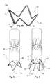
- FIG. 1shows a first embodiment of leg extension for a stent grafting system according to the present invention
- FIG. 2shows a further embodiment of a leg extension for a stent grafting system according to the present invention
- FIG. 3shows a still further embodiment of a leg extension for a stent grafting system according to the present invention
- FIG. 3Ashows detail of the flared stent of the embodiment of FIG. 3 in a laid flat configuration
- FIG. 3Bshows detail of the flared stent of the embodiment of FIG. 3 in a frusto-conical configuration
- FIG. 4shows a still further embodiment of a leg extension for a stent grafting system according to the present invention
- FIG. 5Ashows an alternative embodiment of a leg extension for a stent grafting system according to the present invention
- FIG. 5Bshows a form of flared stent useful for the connection region of the present invention and in particular the embodiment shown in FIG. 5A ;
- FIG. 6shows an alternative embodiment of a leg extension for a stent grafting system according to the present invention
- FIG. 7shows an outside view of a connection between a branched iliac stent graft and a leg extension for a stent grafting system according to one embodiment of the invention
- FIG. 8shows a longitudinal cross sectional view of the connected components shown in FIG. 7 ;
- FIG. 9shows a schematic view of a stent grafting system incorporating a leg extension according to the present invention assembled within the vasculature of a patient.
- a first embodiment of leg extension 10 for a stent grafting systemcomprises a tubular body 12 of a biocompatible graft material with the tubular body supported by self expanding stents 15 .
- a connection region 14 comprising a flared stent 16 in this embodiment covered by a graft material cover 18is at the distal end 24 of the leg extension 10 .
- the tubular bodyhas a external proximal sealing surface 20 at its proximal end 22 .
- the external proximal sealing surfacehas self expanding stents within the tubular body.
- the distal end 24also has a sealing surface 26 .
- the distal sealing surfacehas self expanding stents within the tubular body.
- the external proximal sealing surface 20is arranged to seal within the leg of a bifurcated stent graft and the distal sealing surface 26 is adapted to seal within the proximal end of a branched iliac stent graft as will be discussed later.
- leg extension 10has been shown as a particular length the length may vary and hence the number of intermediate stents 12 and the length of the tubular body can vary. There may be one, two or more self expanding stents within the sealing regions 20 and 26 and one, two or more self expanding stents 15 outside the tubular body 12 between the sealing regions 20 and 26 .
- FIG. 2shows an alternative embodiment according to the present invention in which the leg extension 30 is substantially similar to that shown in FIG. 1 except that at the distal end 32 of the connection portion 18 there is a resilient ring 34 formed from a shape memory metal such as a nickel alloy nitinol metal stitched to the cover 18 by stitching 36 as well as being attached to the distal bends 33 of the flared stent 16 .
- the resilient ring 34assists in maintaining the flare in the connection portion and hence maintaining a connection as discussed above.
- FIG. 3shows a still further embodiment of a leg extension according to the present invention.
- the leg extension 40comprises a tubular body 42 of a biocompatible graft material with an uncovered stent 44 providing the connection region 46 .
- the uncovered stent 44is a self expanding stent formed into a zig zag frusto conical configuration and is connected by the bends at the narrower end 43 of the stent to one end of the tubular body 42 such that it forms the flared configuration to comprise the connection region 46 .
- FIG. 3Ashows detail of the flared stent of the embodiment of FIG. 3 in a laid flat configuration
- FIG. 3Bshows detail of the flared stent of the embodiment of FIG. 3 in a frusto-conical configuration
- the stent 44comprises struts 47 , proximal bends 48 a and distal bends 48 b between the struts.
- the stentis initially formed into a flat configuration from a shape memory metal wire as shown in FIG. 3A and then after heat treatment is formed into a frusto-conical shape and has a welded, adhered or crimped scarf joint 49 to connect the ends of the wire into a continuous zig-zag shape.
- FIG. 4shows a still further embodiment of a leg extension according to the present invention.
- the leg extension 50has a tubular body 52 of a biocompatible graft material and the connection region 54 comprises a zig zag stent 56 which is partially covered by a biocompatible graft material 58 .
- alternate gaps between pairs of adjacent strutsare left bare or uncovered.
- FIG. 5Ashows a still further embodiment of a stent graft according to the present invention.
- the leg extension stent graft 60comprises a tubular body 62 of biocompatible graft material with a four lobed stent 64 fastened to the distal end 66 .
- a covering of graft material 68is stitched along the struts of the four lobed stent 64 to provide a petal effect.
- the stent 64is a self expanding stent formed into a zig zag configuration from a shape memory metal such as the nickel alloy nitinol metal.
- FIG. 5Bshows the form of stent according to the embodiment of the invention shown in FIG. 5A .
- the stent 64is formed from a single length of nitinol wire which commences at a loop 70 adjacent a bend 70 a and forms a series of struts 74 with bends 76 in between them for two circuits before terminating at loop 72 adjacent to bend 72 a with an overlap of one extra strut.
- the wiremay be 0.15 mm diameter.
- the wireis formed into the four lobed frusto-conical shape and then heat treated to memorize that shape.
- FIG. 6shows a still further embodiment of a leg extension according to the present invention.
- the leg extension 61comprises a tubular body 63 of a biocompatible graft material with an uncovered stent 65 providing the connection region 67 .
- the uncovered stent 65is a self expanding stent formed into a zig zag frusto conical configuration and is connected by the bends 69 at the narrower end of the stent to one end of the tubular body 63 such that it forms the flared configuration to comprise the connection region 67 .
- a ring 68formed from a shape memory metal such as a nickel alloy nitinol wire is stitched to the outer bends.
- FIG. 7 and FIG. 8show one arrangement by which a leg extension according to the present invention is connected into a branched iliac stent graft.
- the branched iliac stent graft 80comprises a tubular body 82 of a biocompatible graft material and a side arm 84 extending from the tubular body. At the proximal end of the tubular body is a ring reinforcement 86 .
- the leg extension 10of the type shown in FIG.
- FIG. 9shows a schematic view of the vasculature of a patient particularly showing the aorta and aortic bifurcation extending down towards the iliac arteries.
- the vasculaturecomprises an aorta 100 in the region between the renal arteries 102 and the aortic bifurcation 104 .
- Common iliac arteries 106 and 108extend from the aortic bifurcation 104 .
- the common iliac arteries 106 and 108each bifurcate into internal iliac arteries 110 and 112 and external iliac arteries 114 and 116 respectively.
- the aorta 100has an aneurysm 118 which also extends down the common iliac artery 106 towards the iliac bifurcation 117 .
- a bifurcated aortic stent graft 120has been deployed into the aorta 100 .
- the proximal end 122 of the bifurcated stent graft 120is engaged onto a non-aneurysed portion 124 of the aorta just distal of the renal arteries.
- the stent graft 120includes a supra renal exposed stent 126 with barbs 128 engaging the wall of the aorta proximal of the renal arteries 102 .
- the stent graft 120has a short leg 130 and a long leg 132 extending from a bifurcation 134 at its distal end 136 .
- the long leg 132has a sealing surface 138 at its distal end and this engages in a sealing manner into an non-aneurysed portion of the common iliac artery 108 .
- the aneurysm in the common iliac artery 106requires the placement of an iliac stent graft 140 with a branch 142 from which a covered extension piece 144 can extend down the internal iliac artery 110 .
- the distal end 148 of the iliac stent graft 140engages in a sealing manner into an non-aneurysed portion of the external iliac artery 114 .
- the short leg 130does not extend down to the aortic bifurcation and hence it is necessary to provide an iliac extension piece 150 which goes between the short leg 130 of the bifurcated aortic stent graft 120 and the proximal end 152 of the iliac stent graft 140 . It is to the configuration of this iliac extension piece 150 that the present invention is directed.
- the iliac extension piece 150can be any of the embodiments shown in FIGS. 1 to 6 depending upon the requirements of a particular situation.
- the leg extension 150extends into the lumen of the branched iliac graft 140 at the proximal end 152 of the branched iliac stent graft 140 and extends into the tubular body thereof until its flared connection region fits into the wider portion of the branched iliac stent graft where the side arm 142 extends from the tubular body. With the flared portion extending into the expanded portion on the tubular body a good connection between the two components is obtained even though there is a relatively short overlap.
Landscapes
- Health & Medical Sciences (AREA)
- Gastroenterology & Hepatology (AREA)
- Pulmonology (AREA)
- Cardiology (AREA)
- Oral & Maxillofacial Surgery (AREA)
- Transplantation (AREA)
- Engineering & Computer Science (AREA)
- Biomedical Technology (AREA)
- Heart & Thoracic Surgery (AREA)
- Vascular Medicine (AREA)
- Life Sciences & Earth Sciences (AREA)
- Animal Behavior & Ethology (AREA)
- General Health & Medical Sciences (AREA)
- Public Health (AREA)
- Veterinary Medicine (AREA)
- Prostheses (AREA)
Abstract
Description
Claims (8)
Priority Applications (2)
| Application Number | Priority Date | Filing Date | Title |
|---|---|---|---|
| US11/894,227US8021412B2 (en) | 2006-08-18 | 2007-08-20 | Iliac extension with flared cuff |
| US13/211,759US8449600B2 (en) | 2006-08-18 | 2011-08-17 | Iliac extension with flared cuff |
Applications Claiming Priority (2)
| Application Number | Priority Date | Filing Date | Title |
|---|---|---|---|
| US83896306P | 2006-08-18 | 2006-08-18 | |
| US11/894,227US8021412B2 (en) | 2006-08-18 | 2007-08-20 | Iliac extension with flared cuff |
Related Child Applications (1)
| Application Number | Title | Priority Date | Filing Date |
|---|---|---|---|
| US13/211,759DivisionUS8449600B2 (en) | 2006-08-18 | 2011-08-17 | Iliac extension with flared cuff |
Publications (2)
| Publication Number | Publication Date |
|---|---|
| US20080046065A1 US20080046065A1 (en) | 2008-02-21 |
| US8021412B2true US8021412B2 (en) | 2011-09-20 |
Family
ID=38814448
Family Applications (2)
| Application Number | Title | Priority Date | Filing Date |
|---|---|---|---|
| US11/894,227Active2028-06-01US8021412B2 (en) | 2006-08-18 | 2007-08-20 | Iliac extension with flared cuff |
| US13/211,759Active2027-12-05US8449600B2 (en) | 2006-08-18 | 2011-08-17 | Iliac extension with flared cuff |
Family Applications After (1)
| Application Number | Title | Priority Date | Filing Date |
|---|---|---|---|
| US13/211,759Active2027-12-05US8449600B2 (en) | 2006-08-18 | 2011-08-17 | Iliac extension with flared cuff |
Country Status (5)
| Country | Link |
|---|---|
| US (2) | US8021412B2 (en) |
| EP (1) | EP2068761B1 (en) |
| JP (1) | JP5392655B2 (en) |
| AU (1) | AU2007284361B2 (en) |
| WO (1) | WO2008021556A1 (en) |
Cited By (18)
| Publication number | Priority date | Publication date | Assignee | Title |
|---|---|---|---|---|
| US20090125095A1 (en)* | 2007-11-01 | 2009-05-14 | Cook Incorporated | Flexible stent graft |
| US20110022154A1 (en)* | 2007-08-08 | 2011-01-27 | Hamer Rochelle M | Endoluminal prosthetic conduit systems and method of coupling |
| AU2013207592B1 (en)* | 2013-07-11 | 2013-11-14 | Cook Medical Technologies Llc | An iliac stent graft |
| US8709068B2 (en) | 2007-03-05 | 2014-04-29 | Endospan Ltd. | Multi-component bifurcated stent-graft systems |
| US9427339B2 (en) | 2011-10-30 | 2016-08-30 | Endospan Ltd. | Triple-collar stent-graft |
| US20160287376A1 (en)* | 2012-04-12 | 2016-10-06 | Sanford Health | Combination Double-Barreled and Debranching Stent Grafts and Methods for Use |
| US9545324B2 (en) | 2013-03-13 | 2017-01-17 | Cook Medical Technologies Llc | Pre-loaded iliac branch device and methods of deployment |
| US9597204B2 (en) | 2011-12-04 | 2017-03-21 | Endospan Ltd. | Branched stent-graft system |
| US9770350B2 (en) | 2012-05-15 | 2017-09-26 | Endospan Ltd. | Stent-graft with fixation elements that are radially confined for delivery |
| US9839510B2 (en) | 2011-08-28 | 2017-12-12 | Endospan Ltd. | Stent-grafts with post-deployment variable radial displacement |
| US9918825B2 (en) | 2009-06-23 | 2018-03-20 | Endospan Ltd. | Vascular prosthesis for treating aneurysms |
| US9956101B2 (en) | 2014-12-04 | 2018-05-01 | Trivascular, Inc. | Internal iliac preservation devices and methods |
| US9993360B2 (en) | 2013-01-08 | 2018-06-12 | Endospan Ltd. | Minimization of stent-graft migration during implantation |
| US10350052B2 (en) | 2012-04-12 | 2019-07-16 | Sanford Health | Debranching visceral stent graft and methods for use |
| US10470871B2 (en) | 2001-12-20 | 2019-11-12 | Trivascular, Inc. | Advanced endovascular graft |
| US10485684B2 (en) | 2014-12-18 | 2019-11-26 | Endospan Ltd. | Endovascular stent-graft with fatigue-resistant lateral tube |
| US10603197B2 (en) | 2013-11-19 | 2020-03-31 | Endospan Ltd. | Stent system with radial-expansion locking |
| US11311397B2 (en) | 2019-10-23 | 2022-04-26 | Medtronic Vascular, Inc. | Branch stent graft and delivery method for endovascular treatment of the iliac artery aneurysms |
Families Citing this family (52)
| Publication number | Priority date | Publication date | Assignee | Title |
|---|---|---|---|---|
| DE10221076A1 (en)* | 2002-05-11 | 2003-11-27 | Ruesch Willy Gmbh | stent |
| US9198786B2 (en) | 2003-09-03 | 2015-12-01 | Bolton Medical, Inc. | Lumen repair device with capture structure |
| US7763063B2 (en) | 2003-09-03 | 2010-07-27 | Bolton Medical, Inc. | Self-aligning stent graft delivery system, kit, and method |
| US11259945B2 (en) | 2003-09-03 | 2022-03-01 | Bolton Medical, Inc. | Dual capture device for stent graft delivery system and method for capturing a stent graft |
| US8500792B2 (en) | 2003-09-03 | 2013-08-06 | Bolton Medical, Inc. | Dual capture device for stent graft delivery system and method for capturing a stent graft |
| US11596537B2 (en) | 2003-09-03 | 2023-03-07 | Bolton Medical, Inc. | Delivery system and method for self-centering a proximal end of a stent graft |
| US20080264102A1 (en) | 2004-02-23 | 2008-10-30 | Bolton Medical, Inc. | Sheath Capture Device for Stent Graft Delivery System and Method for Operating Same |
| US20070198078A1 (en)* | 2003-09-03 | 2007-08-23 | Bolton Medical, Inc. | Delivery system and method for self-centering a Proximal end of a stent graft |
| US8292943B2 (en) | 2003-09-03 | 2012-10-23 | Bolton Medical, Inc. | Stent graft with longitudinal support member |
| WO2008021556A1 (en) | 2006-08-18 | 2008-02-21 | William A. Cook Australia Pty. Ltd. | Stent graft extension |
| US9180030B2 (en) | 2007-12-26 | 2015-11-10 | Cook Medical Technologies Llc | Low profile non-symmetrical stent |
| US8574284B2 (en) | 2007-12-26 | 2013-11-05 | Cook Medical Technologies Llc | Low profile non-symmetrical bare alignment stents with graft |
| US9226813B2 (en) | 2007-12-26 | 2016-01-05 | Cook Medical Technologies Llc | Low profile non-symmetrical stent |
| US8992593B2 (en)* | 2007-12-26 | 2015-03-31 | Cook Medical Technologies Llc | Apparatus and methods for deployment of a modular stent-graft system |
| GB2476451A (en) | 2009-11-19 | 2011-06-29 | Cook William Europ | Stent Graft |
| US20090287145A1 (en)* | 2008-05-15 | 2009-11-19 | Altura Interventional, Inc. | Devices and methods for treatment of abdominal aortic aneurysms |
| CN102076281B (en) | 2008-06-30 | 2014-11-05 | 波顿医疗公司 | Systems and methods for abdominal aortic aneurysm |
| US9050184B2 (en) | 2008-08-13 | 2015-06-09 | Allergan, Inc. | Dual plane breast implant |
| EP3284447B1 (en) | 2009-03-13 | 2020-05-20 | Bolton Medical Inc. | System for deploying an endoluminal prosthesis at a surgical site |
| US9757263B2 (en) | 2009-11-18 | 2017-09-12 | Cook Medical Technologies Llc | Stent graft and introducer assembly |
| EP2506799A4 (en)* | 2009-12-01 | 2014-10-29 | Altura Medical Inc | Modular endograft devices and associated systems and methods |
| WO2012040240A1 (en) | 2010-09-20 | 2012-03-29 | Altura Medical, Inc. | Stent graft delivery systems and associated methods |
| US8753386B2 (en)* | 2010-11-15 | 2014-06-17 | W. L. Gore & Associates, Inc. | Stent-graft having facing side branch portals |
| WO2013059623A1 (en)* | 2011-10-21 | 2013-04-25 | Merit Medical Systems, Inc. | Devices and methods for stenting an airway |
| EP2846743B1 (en) | 2012-04-12 | 2016-12-14 | Bolton Medical Inc. | Vascular prosthetic delivery device |
| DK2836162T3 (en)* | 2012-04-12 | 2016-09-05 | Sanford Health | AORTABUESTENT GRAFT WITH DOUBLE-CROSSED MAIN BODIES AND METHODS OF USE |
| US8882828B2 (en) | 2012-04-27 | 2014-11-11 | Medtronic Vascular, Inc. | Ring on a closed web stent-graft for use in tip capture |
| CA2881535A1 (en) | 2012-08-10 | 2014-02-13 | Altura Medical, Inc. | Stent delivery systems and associated methods |
| DE102012111225A1 (en) | 2012-11-21 | 2014-05-22 | Jotec Gmbh | Vascular implant with lateral branch |
| MX360302B (en) | 2012-12-14 | 2018-10-29 | Sanford Health | Combination double-barreled and debranching stent grafts. |
| US10561509B2 (en) | 2013-03-13 | 2020-02-18 | DePuy Synthes Products, Inc. | Braided stent with expansion ring and method of delivery |
| WO2014144809A1 (en)* | 2013-03-15 | 2014-09-18 | Altura Medical, Inc. | Endograft device delivery systems and associated methods |
| US9439751B2 (en) | 2013-03-15 | 2016-09-13 | Bolton Medical, Inc. | Hemostasis valve and delivery systems |
| AU2013206465B1 (en)* | 2013-06-18 | 2014-01-16 | Cook Medical Technologies Llc | Endovascular graft with an expanded lumen at a bifurcation |
| US9956096B2 (en)* | 2013-08-15 | 2018-05-01 | Cook Medical Technologies Llc | Assembly for treating branched vessels |
| US9662232B2 (en)* | 2014-04-11 | 2017-05-30 | Red Vascular Technologies, LLC | Alignment system for multiple branch endografts |
| US10206796B2 (en) | 2014-08-27 | 2019-02-19 | DePuy Synthes Products, Inc. | Multi-strand implant with enhanced radiopacity |
| US10076428B2 (en) | 2016-08-25 | 2018-09-18 | DePuy Synthes Products, Inc. | Expansion ring for a braided stent |
| US10292851B2 (en) | 2016-09-30 | 2019-05-21 | DePuy Synthes Products, Inc. | Self-expanding device delivery apparatus with dual function bump |
| WO2018134368A1 (en)* | 2017-01-20 | 2018-07-26 | Syddansk Universitet | Monolithic aorto-iliac preservation stent graft |
| AU2019204522A1 (en) | 2018-07-30 | 2020-02-13 | DePuy Synthes Products, Inc. | Systems and methods of manufacturing and using an expansion ring |
| US10456280B1 (en) | 2018-08-06 | 2019-10-29 | DePuy Synthes Products, Inc. | Systems and methods of using a braided implant |
| US10278848B1 (en) | 2018-08-06 | 2019-05-07 | DePuy Synthes Products, Inc. | Stent delivery with expansion assisting delivery wire |
| EP3849468A4 (en)* | 2018-09-12 | 2022-05-25 | Endologix LLC | INFLATABLE INFLATING STRUCTURE AND INFLATABLE CUFF STENT GRAFT SYSTEMS AND PROCEDURES |
| CN109464213B (en)* | 2018-12-20 | 2020-12-15 | 深圳市先健畅通医疗有限公司 | Covered stent and covered stent system |
| US11039944B2 (en) | 2018-12-27 | 2021-06-22 | DePuy Synthes Products, Inc. | Braided stent system with one or more expansion rings |
| US11219518B2 (en)* | 2019-11-15 | 2022-01-11 | Medtronic Vascular, Inc. | Oblique seam for reduced stent graft packing density in delivery system |
| RU2742451C1 (en)* | 2020-03-04 | 2021-02-05 | Заза Александрович Кавтеладзе | Bifurcation stent-graft system for treating aneurism of abdominal aorta and method of treating aneurism of abdominal aorta using thereof |
| EP4585192A3 (en) | 2020-06-24 | 2025-10-15 | Bolton Medical, Inc. | Anti-backspin component for vascular prosthesis delivery device |
| KR102575514B1 (en)* | 2021-06-23 | 2023-09-06 | 재단법인 아산사회복지재단 | Eustachian tube stent and manufacturing method thereof |
| EP4568616A2 (en)* | 2022-08-09 | 2025-06-18 | The General Hospital Corporation | Endovascular biologic stent |
| US20240156622A1 (en)* | 2022-11-15 | 2024-05-16 | Merit Medical Systems, Inc. | Balloon expandable stent prostheses and balloon expandable branching stent prostheses |
Citations (27)
| Publication number | Priority date | Publication date | Assignee | Title |
|---|---|---|---|---|
| US4502159A (en) | 1982-08-12 | 1985-03-05 | Shiley Incorporated | Tubular prostheses prepared from pericardial tissue |
| US5711969A (en) | 1995-04-07 | 1998-01-27 | Purdue Research Foundation | Large area submucosal tissue graft constructs |
| US5720776A (en)* | 1991-10-25 | 1998-02-24 | Cook Incorporated | Barb and expandable transluminal graft prosthesis for repair of aneurysm |
| WO1998053761A1 (en) | 1997-05-26 | 1998-12-03 | William A. Cook Australia Pty. Ltd. | A prosthesis and a method and means of deploying a prosthesis |
| US5922019A (en)* | 1995-11-27 | 1999-07-13 | Schneider (Europe) A.G. | Conical stent |
| US5968096A (en) | 1996-04-05 | 1999-10-19 | Purdue Research Foundation | Method of repairing perforated submucosal tissue graft constructs |
| US6033435A (en)* | 1997-11-03 | 2000-03-07 | Divysio Solutions Ulc | Bifurcated stent and method for the manufacture and delivery of same |
| US6206931B1 (en) | 1996-08-23 | 2001-03-27 | Cook Incorporated | Graft prosthesis materials |
| US6358284B1 (en) | 1996-12-10 | 2002-03-19 | Med Institute, Inc. | Tubular grafts from purified submucosa |
| US6379710B1 (en) | 1996-12-10 | 2002-04-30 | Purdue Research Foundation | Biomaterial derived from vertebrate liver tissue |
| US20020065552A1 (en) | 2000-08-23 | 2002-05-30 | Jayaraman Ramesh B. | Coated vascular grafts and methods of use |
| US20030163188A1 (en)* | 2002-02-22 | 2003-08-28 | Haverkost Patrick A. | Method and system for deploying multi-part endoluminal devices |
| WO2003082153A2 (en) | 2002-03-25 | 2003-10-09 | Cook Incorporated | Branched vessel prothesis |
| US6645242B1 (en)* | 2000-12-11 | 2003-11-11 | Stephen F. Quinn | Bifurcated side-access intravascular stent graft |
| US6666892B2 (en) | 1996-08-23 | 2003-12-23 | Cook Biotech Incorporated | Multi-formed collagenous biomaterial medical device |
| US6695875B2 (en) | 2000-03-14 | 2004-02-24 | Cook Incorporated | Endovascular stent graft |
| WO2004017867A1 (en) | 2002-08-23 | 2004-03-04 | William A. Cook Australia Pty. Ltd. | Composite prosthesis |
| US6814752B1 (en)* | 2000-03-03 | 2004-11-09 | Endovascular Technologies, Inc. | Modular grafting system and method |
| WO2005032340A2 (en) | 2003-09-29 | 2005-04-14 | Secant Medical, Llc | Integral support stent graft assembly |
| WO2005034808A1 (en) | 2003-10-10 | 2005-04-21 | William A. Cook Australia Pty. Ltd. | Fenestrated stent grafts |
| WO2005044148A1 (en) | 2003-10-24 | 2005-05-19 | Aptus Endosystems, Inc. | Multi-lumen prosthesis systems and methods |
| US6945992B2 (en)* | 2003-04-22 | 2005-09-20 | Medtronic Vascular, Inc. | Single-piece crown stent |
| US20060100686A1 (en) | 2001-11-28 | 2006-05-11 | Aptus Endosystems, Inc. | Devices, systems, and methods for prosthesis delivery and implantation |
| US20060287704A1 (en)* | 2005-06-01 | 2006-12-21 | William A. Cook Australia Pty. Ltd. | Iliac artery stent graft |
| US20070233227A1 (en)* | 2006-03-30 | 2007-10-04 | Medtronic Vascular, Inc. | Prosthesis With Coupling Zone and Methods |
| WO2008021557A1 (en) | 2006-08-18 | 2008-02-21 | William A. Cook Australia Pty. Ltd. | Stent graft |
| WO2008021556A1 (en) | 2006-08-18 | 2008-02-21 | William A. Cook Australia Pty. Ltd. | Stent graft extension |
Family Cites Families (6)
| Publication number | Priority date | Publication date | Assignee | Title |
|---|---|---|---|---|
| US6045557A (en)* | 1995-11-10 | 2000-04-04 | Baxter International Inc. | Delivery catheter and method for positioning an intraluminal graft |
| GB2378137A (en)* | 2001-07-31 | 2003-02-05 | John Reece Jenkins | A stent comprising a framework of shape memory metal |
| EP3424463A1 (en)* | 2003-11-08 | 2019-01-09 | Cook Medical Technologies LLC | Aorta and branch vessel stent grafts and system |
| US20050192659A1 (en)* | 2004-01-23 | 2005-09-01 | Terry Dahl | Apparatus and method for performing a surgical procedure |
| US20060064036A1 (en)* | 2004-09-21 | 2006-03-23 | Cook Incorporated | Variable flexibility wire guide |
| US8864819B2 (en)* | 2004-12-17 | 2014-10-21 | Cook Medical Technologies Llc | Stented side branch graft |
- 2007
- 2007-08-20WOPCT/US2007/018409patent/WO2008021556A1/enactiveApplication Filing
- 2007-08-20JPJP2009524705Apatent/JP5392655B2/enactiveActive
- 2007-08-20USUS11/894,227patent/US8021412B2/enactiveActive
- 2007-08-20AUAU2007284361Apatent/AU2007284361B2/enactiveActive
- 2007-08-20EPEP07837089.7Apatent/EP2068761B1/enactiveActive
- 2011
- 2011-08-17USUS13/211,759patent/US8449600B2/enactiveActive
Patent Citations (32)
| Publication number | Priority date | Publication date | Assignee | Title |
|---|---|---|---|---|
| US4502159A (en) | 1982-08-12 | 1985-03-05 | Shiley Incorporated | Tubular prostheses prepared from pericardial tissue |
| US5720776A (en)* | 1991-10-25 | 1998-02-24 | Cook Incorporated | Barb and expandable transluminal graft prosthesis for repair of aneurysm |
| US5711969A (en) | 1995-04-07 | 1998-01-27 | Purdue Research Foundation | Large area submucosal tissue graft constructs |
| US5885619A (en) | 1995-04-07 | 1999-03-23 | Purdue Research Foundation | Large area submucosal tissue graft constructs and method for making the same |
| US5955110A (en) | 1995-04-07 | 1999-09-21 | Purdue Research Foundation, Inc. | Multilayered submucosal graft constructs and method for making the same |
| US5922019A (en)* | 1995-11-27 | 1999-07-13 | Schneider (Europe) A.G. | Conical stent |
| US5968096A (en) | 1996-04-05 | 1999-10-19 | Purdue Research Foundation | Method of repairing perforated submucosal tissue graft constructs |
| US6666892B2 (en) | 1996-08-23 | 2003-12-23 | Cook Biotech Incorporated | Multi-formed collagenous biomaterial medical device |
| US6206931B1 (en) | 1996-08-23 | 2001-03-27 | Cook Incorporated | Graft prosthesis materials |
| US6358284B1 (en) | 1996-12-10 | 2002-03-19 | Med Institute, Inc. | Tubular grafts from purified submucosa |
| US6379710B1 (en) | 1996-12-10 | 2002-04-30 | Purdue Research Foundation | Biomaterial derived from vertebrate liver tissue |
| WO1998053761A1 (en) | 1997-05-26 | 1998-12-03 | William A. Cook Australia Pty. Ltd. | A prosthesis and a method and means of deploying a prosthesis |
| US6033435A (en)* | 1997-11-03 | 2000-03-07 | Divysio Solutions Ulc | Bifurcated stent and method for the manufacture and delivery of same |
| US6814752B1 (en)* | 2000-03-03 | 2004-11-09 | Endovascular Technologies, Inc. | Modular grafting system and method |
| US6695875B2 (en) | 2000-03-14 | 2004-02-24 | Cook Incorporated | Endovascular stent graft |
| US20020065552A1 (en) | 2000-08-23 | 2002-05-30 | Jayaraman Ramesh B. | Coated vascular grafts and methods of use |
| US6645242B1 (en)* | 2000-12-11 | 2003-11-11 | Stephen F. Quinn | Bifurcated side-access intravascular stent graft |
| US20060100686A1 (en) | 2001-11-28 | 2006-05-11 | Aptus Endosystems, Inc. | Devices, systems, and methods for prosthesis delivery and implantation |
| US20030163188A1 (en)* | 2002-02-22 | 2003-08-28 | Haverkost Patrick A. | Method and system for deploying multi-part endoluminal devices |
| WO2003082153A2 (en) | 2002-03-25 | 2003-10-09 | Cook Incorporated | Branched vessel prothesis |
| US20030199967A1 (en)* | 2002-03-25 | 2003-10-23 | Cook Incorporated | Bifurcated/branch vessel prosthesis |
| US20040082990A1 (en)* | 2002-08-23 | 2004-04-29 | William A. Cook Australia Pty. Ltd. | Composite prosthesis |
| WO2004017867A1 (en) | 2002-08-23 | 2004-03-04 | William A. Cook Australia Pty. Ltd. | Composite prosthesis |
| US6945992B2 (en)* | 2003-04-22 | 2005-09-20 | Medtronic Vascular, Inc. | Single-piece crown stent |
| WO2005032340A2 (en) | 2003-09-29 | 2005-04-14 | Secant Medical, Llc | Integral support stent graft assembly |
| WO2005034808A1 (en) | 2003-10-10 | 2005-04-21 | William A. Cook Australia Pty. Ltd. | Fenestrated stent grafts |
| US7413573B2 (en)* | 2003-10-10 | 2008-08-19 | William A. Cook Australia Pty. Ltd. | Fenestrated stent grafts |
| WO2005044148A1 (en) | 2003-10-24 | 2005-05-19 | Aptus Endosystems, Inc. | Multi-lumen prosthesis systems and methods |
| US20060287704A1 (en)* | 2005-06-01 | 2006-12-21 | William A. Cook Australia Pty. Ltd. | Iliac artery stent graft |
| US20070233227A1 (en)* | 2006-03-30 | 2007-10-04 | Medtronic Vascular, Inc. | Prosthesis With Coupling Zone and Methods |
| WO2008021557A1 (en) | 2006-08-18 | 2008-02-21 | William A. Cook Australia Pty. Ltd. | Stent graft |
| WO2008021556A1 (en) | 2006-08-18 | 2008-02-21 | William A. Cook Australia Pty. Ltd. | Stent graft extension |
Non-Patent Citations (3)
| Title |
|---|
| U.S. Appl. No. 60/405,769, filed Aug. 23, 2002, Hartley. |
| U.S. Appl. No. 60/686,252, filed Jun. 1, 2005, Hartley. |
| U.S. Appl. No. 60/838,776, filed Aug. 18, 2006, Chuter. |
Cited By (37)
| Publication number | Priority date | Publication date | Assignee | Title |
|---|---|---|---|---|
| US11439497B2 (en) | 2001-12-20 | 2022-09-13 | Trivascular, Inc. | Advanced endovascular graft |
| US10470871B2 (en) | 2001-12-20 | 2019-11-12 | Trivascular, Inc. | Advanced endovascular graft |
| US8709068B2 (en) | 2007-03-05 | 2014-04-29 | Endospan Ltd. | Multi-component bifurcated stent-graft systems |
| US8979920B2 (en)* | 2007-08-08 | 2015-03-17 | W. L. Gore & Associates, Inc. | Endoluminal prosthetic conduit systems and method of coupling |
| US20140005765A1 (en)* | 2007-08-08 | 2014-01-02 | W.L. Gore & Associates, Inc. | Endoluminal prosthetic conduit systems and method of coupling |
| US8551157B2 (en)* | 2007-08-08 | 2013-10-08 | W. L. Gore & Associates, Inc. | Endoluminal prosthetic conduit systems and method of coupling |
| US20110022154A1 (en)* | 2007-08-08 | 2011-01-27 | Hamer Rochelle M | Endoluminal prosthetic conduit systems and method of coupling |
| US9107741B2 (en) | 2007-11-01 | 2015-08-18 | Cook Medical Technologies Llc | Flexible stent graft |
| US20090125095A1 (en)* | 2007-11-01 | 2009-05-14 | Cook Incorporated | Flexible stent graft |
| US10028849B2 (en) | 2007-11-01 | 2018-07-24 | Cook Medical Technologies Llc | Flexible stent graft |
| US11090148B2 (en) | 2009-06-23 | 2021-08-17 | Endospan Ltd. | Vascular prosthesis for treating aneurysms |
| US9918825B2 (en) | 2009-06-23 | 2018-03-20 | Endospan Ltd. | Vascular prosthesis for treating aneurysms |
| US9839510B2 (en) | 2011-08-28 | 2017-12-12 | Endospan Ltd. | Stent-grafts with post-deployment variable radial displacement |
| US9427339B2 (en) | 2011-10-30 | 2016-08-30 | Endospan Ltd. | Triple-collar stent-graft |
| US9597204B2 (en) | 2011-12-04 | 2017-03-21 | Endospan Ltd. | Branched stent-graft system |
| US10492900B2 (en) | 2012-04-12 | 2019-12-03 | Sanford Health | Debranching great vessel stent graft and methods for use |
| US12201511B2 (en) | 2012-04-12 | 2025-01-21 | Sanford Health | Debranching visceral stent grant and methods for use |
| US10350052B2 (en) | 2012-04-12 | 2019-07-16 | Sanford Health | Debranching visceral stent graft and methods for use |
| US10357353B2 (en)* | 2012-04-12 | 2019-07-23 | Sanford Health | Combination double-barreled and debranching stent grafts and methods for use |
| US20160287376A1 (en)* | 2012-04-12 | 2016-10-06 | Sanford Health | Combination Double-Barreled and Debranching Stent Grafts and Methods for Use |
| US12023237B2 (en) | 2012-04-12 | 2024-07-02 | Sanford Health | Debranching visceral stent grant and methods for use |
| US11419713B2 (en) | 2012-04-12 | 2022-08-23 | Sanford Health | Debranching visceral stent graft and methods for use |
| US11998441B2 (en) | 2012-04-12 | 2024-06-04 | Sanford Health | Debranching visceral stent grant and methods for use |
| US9770350B2 (en) | 2012-05-15 | 2017-09-26 | Endospan Ltd. | Stent-graft with fixation elements that are radially confined for delivery |
| US9993360B2 (en) | 2013-01-08 | 2018-06-12 | Endospan Ltd. | Minimization of stent-graft migration during implantation |
| US9545324B2 (en) | 2013-03-13 | 2017-01-17 | Cook Medical Technologies Llc | Pre-loaded iliac branch device and methods of deployment |
| US9408689B2 (en) | 2013-07-11 | 2016-08-09 | Cook Medical Technologies Llc | Iliac stent graft |
| AU2013207592B1 (en)* | 2013-07-11 | 2013-11-14 | Cook Medical Technologies Llc | An iliac stent graft |
| US10603197B2 (en) | 2013-11-19 | 2020-03-31 | Endospan Ltd. | Stent system with radial-expansion locking |
| US11918498B2 (en) | 2014-12-04 | 2024-03-05 | Trivascular, Inc. | Internal iliac preservation devices and methods |
| US11033413B2 (en) | 2014-12-04 | 2021-06-15 | Trivascular, Inc. | Internal iliac preservation devices and methods |
| US9956101B2 (en) | 2014-12-04 | 2018-05-01 | Trivascular, Inc. | Internal iliac preservation devices and methods |
| US11419742B2 (en) | 2014-12-18 | 2022-08-23 | Endospan Ltd. | Endovascular stent-graft with fatigue-resistant lateral tube |
| US10485684B2 (en) | 2014-12-18 | 2019-11-26 | Endospan Ltd. | Endovascular stent-graft with fatigue-resistant lateral tube |
| US12193954B2 (en) | 2014-12-18 | 2025-01-14 | Endospan Ltd. | Endovascular stent-graft with fatigue-resistant lateral tube |
| US11311397B2 (en) | 2019-10-23 | 2022-04-26 | Medtronic Vascular, Inc. | Branch stent graft and delivery method for endovascular treatment of the iliac artery aneurysms |
| US12023266B2 (en) | 2019-10-23 | 2024-07-02 | Medtronic Vascular, Inc. | Branch stent graft and delivery method for endovascular treatment of the iliac artery aneurysms |
Also Published As
| Publication number | Publication date |
|---|---|
| JP2010501207A (en) | 2010-01-21 |
| EP2068761B1 (en) | 2019-02-13 |
| JP5392655B2 (en) | 2014-01-22 |
| WO2008021556A1 (en) | 2008-02-21 |
| EP2068761A1 (en) | 2009-06-17 |
| US20080046065A1 (en) | 2008-02-21 |
| AU2007284361A1 (en) | 2008-02-21 |
| US20110301693A1 (en) | 2011-12-08 |
| AU2007284361B2 (en) | 2012-06-14 |
| US8449600B2 (en) | 2013-05-28 |
Similar Documents
| Publication | Publication Date | Title |
|---|---|---|
| US8021412B2 (en) | Iliac extension with flared cuff | |
| US11241320B2 (en) | Stent with a crush-resistant zone | |
| US7645298B2 (en) | Stent graft fenestration | |
| US9358097B2 (en) | Iliac leg extension stent graft | |
| JP4406649B2 (en) | Intraluminal prosthesis for interconnection module related applications | |
| US8043363B2 (en) | Endoluminal prosthesis | |
| US8864819B2 (en) | Stented side branch graft | |
| US20050149166A1 (en) | Branch vessel prosthesis with anchoring device and method | |
| US9931231B2 (en) | Support structures for prostheses with branching portions | |
| AU2012202706B2 (en) | Stent graft extension |
Legal Events
| Date | Code | Title | Description |
|---|---|---|---|
| AS | Assignment | Owner name:COOK INCORPORATED, INDIANA Free format text:ASSIGNMENT OF ASSIGNORS INTEREST;ASSIGNORS:HARTLEY, DAVID E.;DUCKE, WERNER D.;REEL/FRAME:019960/0559 Effective date:20070924 Owner name:WILLIAM A. COOK AUSTRALIA PTY. LTD., AUSTRALIA Free format text:ASSIGNMENT OF ASSIGNORS INTEREST;ASSIGNORS:HARTLEY, DAVID E.;DUCKE, WERNER D.;REEL/FRAME:019960/0559 Effective date:20070924 | |
| AS | Assignment | Owner name:COOK MEDICAL TECHNOLOGIES LLC, INDIANA Free format text:ASSIGNMENT OF ASSIGNORS INTEREST;ASSIGNOR:COOK INCORPORATED;REEL/FRAME:026392/0581 Effective date:20110603 | |
| STCF | Information on status: patent grant | Free format text:PATENTED CASE | |
| AS | Assignment | Owner name:COOK MEDICAL TECHNOLOGIES LLC, INDIANA Free format text:ASSIGNMENT OF ASSIGNORS INTEREST;ASSIGNOR:WILLIAM A. COOK AUSTRALIA PTY. LTD.;REEL/FRAME:030261/0595 Effective date:20130418 | |
| FPAY | Fee payment | Year of fee payment:4 | |
| MAFP | Maintenance fee payment | Free format text:PAYMENT OF MAINTENANCE FEE, 8TH YEAR, LARGE ENTITY (ORIGINAL EVENT CODE: M1552); ENTITY STATUS OF PATENT OWNER: LARGE ENTITY Year of fee payment:8 | |
| MAFP | Maintenance fee payment | Free format text:PAYMENT OF MAINTENANCE FEE, 12TH YEAR, LARGE ENTITY (ORIGINAL EVENT CODE: M1553); ENTITY STATUS OF PATENT OWNER: LARGE ENTITY Year of fee payment:12 | |
| AS | Assignment | Owner name:WILMINGTON TRUST, NATIONAL ASSOCIATION, AS COLLATERAL AGENT, DELAWARE Free format text:SECURITY INTEREST;ASSIGNOR:COOK MEDICAL TECHNOLOGIES LLC;REEL/FRAME:066700/0277 Effective date:20240227 |