US8021402B2 - Distal radius plate - Google Patents
Distal radius plateDownload PDFInfo
- Publication number
- US8021402B2 US8021402B2US11/713,856US71385607AUS8021402B2US 8021402 B2US8021402 B2US 8021402B2US 71385607 AUS71385607 AUS 71385607AUS 8021402 B2US8021402 B2US 8021402B2
- Authority
- US
- United States
- Prior art keywords
- plate
- head
- prominence
- distal
- set forth
- Prior art date
- Legal status (The legal status is an assumption and is not a legal conclusion. Google has not performed a legal analysis and makes no representation as to the accuracy of the status listed.)
- Active, expires
Links
Images


Classifications
- A—HUMAN NECESSITIES
- A61—MEDICAL OR VETERINARY SCIENCE; HYGIENE
- A61B—DIAGNOSIS; SURGERY; IDENTIFICATION
- A61B17/00—Surgical instruments, devices or methods
- A61B17/56—Surgical instruments or methods for treatment of bones or joints; Devices specially adapted therefor
- A61B17/58—Surgical instruments or methods for treatment of bones or joints; Devices specially adapted therefor for osteosynthesis, e.g. bone plates, screws or setting implements
- A61B17/68—Internal fixation devices, including fasteners and spinal fixators, even if a part thereof projects from the skin
- A61B17/80—Cortical plates, i.e. bone plates; Instruments for holding or positioning cortical plates, or for compressing bones attached to cortical plates
- A61B17/8061—Cortical plates, i.e. bone plates; Instruments for holding or positioning cortical plates, or for compressing bones attached to cortical plates specially adapted for particular bones
- A—HUMAN NECESSITIES
- A61—MEDICAL OR VETERINARY SCIENCE; HYGIENE
- A61B—DIAGNOSIS; SURGERY; IDENTIFICATION
- A61B17/00—Surgical instruments, devices or methods
- A61B17/56—Surgical instruments or methods for treatment of bones or joints; Devices specially adapted therefor
- A61B17/58—Surgical instruments or methods for treatment of bones or joints; Devices specially adapted therefor for osteosynthesis, e.g. bone plates, screws or setting implements
- A61B17/68—Internal fixation devices, including fasteners and spinal fixators, even if a part thereof projects from the skin
- A61B17/80—Cortical plates, i.e. bone plates; Instruments for holding or positioning cortical plates, or for compressing bones attached to cortical plates
- A61B17/8052—Cortical plates, i.e. bone plates; Instruments for holding or positioning cortical plates, or for compressing bones attached to cortical plates immobilised relative to screws by interlocking form of the heads and plate holes, e.g. conical or threaded
- A61B17/8057—Cortical plates, i.e. bone plates; Instruments for holding or positioning cortical plates, or for compressing bones attached to cortical plates immobilised relative to screws by interlocking form of the heads and plate holes, e.g. conical or threaded the interlocking form comprising a thread
- A—HUMAN NECESSITIES
- A61—MEDICAL OR VETERINARY SCIENCE; HYGIENE
- A61B—DIAGNOSIS; SURGERY; IDENTIFICATION
- A61B17/00—Surgical instruments, devices or methods
- A61B17/16—Instruments for performing osteoclasis; Drills or chisels for bones; Trepans
- A61B17/17—Guides or aligning means for drills, mills, pins or wires
- A61B17/1728—Guides or aligning means for drills, mills, pins or wires for holes for bone plates or plate screws
- A—HUMAN NECESSITIES
- A61—MEDICAL OR VETERINARY SCIENCE; HYGIENE
- A61B—DIAGNOSIS; SURGERY; IDENTIFICATION
- A61B17/00—Surgical instruments, devices or methods
- A61B17/16—Instruments for performing osteoclasis; Drills or chisels for bones; Trepans
- A61B17/17—Guides or aligning means for drills, mills, pins or wires
- A61B17/1739—Guides or aligning means for drills, mills, pins or wires specially adapted for particular parts of the body
- A61B17/1782—Guides or aligning means for drills, mills, pins or wires specially adapted for particular parts of the body for the hand or wrist
- A—HUMAN NECESSITIES
- A61—MEDICAL OR VETERINARY SCIENCE; HYGIENE
- A61B—DIAGNOSIS; SURGERY; IDENTIFICATION
- A61B17/00—Surgical instruments, devices or methods
- A61B17/56—Surgical instruments or methods for treatment of bones or joints; Devices specially adapted therefor
- A61B17/58—Surgical instruments or methods for treatment of bones or joints; Devices specially adapted therefor for osteosynthesis, e.g. bone plates, screws or setting implements
- A61B17/68—Internal fixation devices, including fasteners and spinal fixators, even if a part thereof projects from the skin
- A61B17/80—Cortical plates, i.e. bone plates; Instruments for holding or positioning cortical plates, or for compressing bones attached to cortical plates
- A61B17/8033—Cortical plates, i.e. bone plates; Instruments for holding or positioning cortical plates, or for compressing bones attached to cortical plates having indirect contact with screw heads, or having contact with screw heads maintained with the aid of additional components, e.g. nuts, wedges or head covers
- A61B17/8047—Cortical plates, i.e. bone plates; Instruments for holding or positioning cortical plates, or for compressing bones attached to cortical plates having indirect contact with screw heads, or having contact with screw heads maintained with the aid of additional components, e.g. nuts, wedges or head covers wherein the additional element surrounds the screw head in the plate hole
- A—HUMAN NECESSITIES
- A61—MEDICAL OR VETERINARY SCIENCE; HYGIENE
- A61B—DIAGNOSIS; SURGERY; IDENTIFICATION
- A61B17/00—Surgical instruments, devices or methods
- A61B17/56—Surgical instruments or methods for treatment of bones or joints; Devices specially adapted therefor
- A61B17/58—Surgical instruments or methods for treatment of bones or joints; Devices specially adapted therefor for osteosynthesis, e.g. bone plates, screws or setting implements
- A61B17/68—Internal fixation devices, including fasteners and spinal fixators, even if a part thereof projects from the skin
- A61B17/80—Cortical plates, i.e. bone plates; Instruments for holding or positioning cortical plates, or for compressing bones attached to cortical plates
- A61B17/8052—Cortical plates, i.e. bone plates; Instruments for holding or positioning cortical plates, or for compressing bones attached to cortical plates immobilised relative to screws by interlocking form of the heads and plate holes, e.g. conical or threaded
- A—HUMAN NECESSITIES
- A61—MEDICAL OR VETERINARY SCIENCE; HYGIENE
- A61B—DIAGNOSIS; SURGERY; IDENTIFICATION
- A61B17/00—Surgical instruments, devices or methods
- A61B17/56—Surgical instruments or methods for treatment of bones or joints; Devices specially adapted therefor
- A61B17/58—Surgical instruments or methods for treatment of bones or joints; Devices specially adapted therefor for osteosynthesis, e.g. bone plates, screws or setting implements
- A61B17/68—Internal fixation devices, including fasteners and spinal fixators, even if a part thereof projects from the skin
- A61B17/84—Fasteners therefor or fasteners being internal fixation devices
- A61B17/86—Pins or screws or threaded wires; nuts therefor
- A61B17/8605—Heads, i.e. proximal ends projecting from bone
Definitions
- the present inventionrelates to an orthopedic plate for fixation of the radius bone, and further in particular to the distal terminus or head of a distal radial plate for internal fixation of a distal radial fracture.
- the wristis the joint formed at the intersection of the radius, the ulna, the carpals and the metacarpals.
- the wristis the most frequently injured area of the upper extremity with three fourths of wrist injuries involving a fracture of the distal radius, and/or of the radius. These injuries usually present in an emergency room setting, and often involve a fall on an outstretched hand. While the past conventional wisdom has included a belief that such injuries will tend to heal sufficiently on their own, there is often a loss of function and an early onset of arthritis that can be precipitated by the misdiagnosis and improper treatment of such injuries.
- the treatments known for wrist traumahave included external stabilization and fixation such as by plaster casts, external fixators, and orthopedic plates. Casting alone, presents the possibility of misalignment of the fragments which can lead to severe loss of function and early onset of arthritis, if the fracture is not properly reduced, and/or if the fragments do not stay in a reduced state, in particular where the patient is not compliant.
- External fixatorshave been demonstrated to have an efficacy, but are cumbersome, cosmetically unappealing, and can lead to the possibility of infection at the attachment sites.
- the plate in accordance with the present inventionhas a distal portion or head having a profile which flares from the sides of the plate to a leading edge that includes a central oblique linking area that helps to mark the placement of the plate relative to the radius.
- the headis shaped like a heart where the lobes have been asymmetrically truncated, like the palm of a hand, or like a modified kidney shape.
- the plateis designed to specifically accommodate the distal portion of the radial bone and further is provided in a right hand and left hand version, which are mirror images of each other.
- the thumb side of the headincludes the most distally extending prominence, which also includes the highest elevation and is shaped to buttress the volar surface of the radial styloid.
- the front edge of the headincludes the central skewed or oblique linking area, which is a small oblique edge about two thirds of the way across the distal edge that leads from a first relatively transverse edge area into the second edge area of the distal edge that extends at a slight diagonal angle relative to the first edge area across the distal radius to a second prominence which sits under the ridge of the lunate fossa.
- the head profilecurves upward, and outward from the proximal plate portion in a first rounded side into a first prominence which is the styloid prominence of the head to support the radial styloid on the volar side of the radius, and in a second rounded side on the other side to a second prominence which is the lunate prominence of the head to support the ridge of the lunate fossa on the volar side.
- the distal edge of the headforms two more or less, transverse segments between the first and second prominences with a skewed edge linking the first and second segments.
- the skewed areais intended to help locate the depression which is located toward the center of the radial bone, at the volar terminal of the ridge of the lunate fossa.
- the headhas a complex topography in the Z direction which echoes a generalized shape for the distal volar surface of a radius.
- the lunate prominence of the headhas a lower elevation in the Z direction than the elevation of the styloid prominence in the direction relative to the radius.
- the longitudinal axis at the center of the proximal portion of the bonedefines the Y direction, and the X direction extends transverse in a direction in which the bone widens.
- the plateincludes an oblique depression, or cup, that extends from the rounded pinky side of the head and gradually morphs into the elevated styloid prominence in one diagonal direction and rises less gradually upward into the lunate prominence on the other side of the head.
- This distal cupundulates to define a superficial (i.e. relative to its surface) serpentine as it links into the proximal portion of the plate.
- the platemimics the spiral of the radial bone as it extends proximally away from the distal portion.
- the proximal portion of the plateappears to twist or spiral along the longitudinal axis, and includes a tighter radial bend as it extends proximally since the bone becomes smaller and more circular in cross-section.
- the platecurves along the longitudinal axis in the X direction toward the thumb side.
- the plateis designed in general to accommodate the goal of being thick and/or rigid enough to provide optimal stabilization, and yet being as thin and therefore minimally invasive as possible given the general abundance of ligaments, blood vessels, and nerves in the indicated area.
- Strengthis an issue for radial plates as the area of the distal radius is subject to surprisingly large forces that are generated by the tendons and ligaments of the hands in gripping objects.
- the plateis somewhat thicker in the neck area to provide for additional strength at the junction of the head and the proximal portion of the plate.
- the headpreferably includes holes or bores for pegs which extend into the distal portion of the radius to lock fragments into position.
- the plateis provided in a first and a second embodiment relative to the peg holes.
- the angles of the pegsare fixed, and more specifically, the angles of the axes of the pegs are fixed relative to an arbitrary origin located in the center of one of the screw holes in the proximal portion of the plate.
- the peg holesare threaded, and the peg angles are determined first by using a drill guide, which is in particular an individual drill guide that may be threaded into the threads of the peg hole (or may be tapered to allow for a friction fit, depending on the preference of the surgeon) and subsequently used to drill a guide hole into the bone.
- a drill guidewhich is in particular an individual drill guide that may be threaded into the threads of the peg hole (or may be tapered to allow for a friction fit, depending on the preference of the surgeon) and subsequently used to drill a guide hole into the bone.
- the pegsare threaded only at the top section although they may alternatively, or in combination, include threads along the body portion that is used to lock the bone into position relative to the plate.
- the threaded head of the pegsalso preferably includes a taper in the minor diameter, which allows the peg to be locked into position in the plate as they are drawn into the closed position.
- the first hole and the fourth holethere are a plurality of fixed peg holes, including one in each of the styloid and lunate prominences (the first hole and the fourth hole), which splay outward and away from the plate such that they diverge away from one another to be capable of locking a styloid fragment and/or a fragment from the lunate fossa portion of the radial bone.
- a second hole, most distal holeis located generally under the skewed linking area of the head, which defines a peg axis that extends through the radius and distally toward the scaphoid or navicular bone and a third hole is distally aligned between the two holes of the prominences but is slightly backed off proximally from the second hole, with a peg axis that is more transverse than the peg axis of the second hole.
- the fourth peg holeis the hole of the lunate prominence which is slightly more proximal than the first hole which is located in the styloid prominence.
- a fifth holeis located in the first rounded side, which is on the styloid or thumbward side, toward the intersection between the proximal portion of the plate, and the plate head.
- the axis defined by this holediverges outwardly toward the lateral portion of the radius (in a supine position).
- a sixth holeis located in a central portion of the head such as on a longitudinal axis of the plate, and a final seventh hole is located most proximally at the intersection of the head and the proximal portion of the plate, with the axis of the peg appearing to be more or less transverse relative to the plane defined by the opening of the peg hole.
- one or more peg holeshave a variable axis and one of more peg holes have an axis which is fixed.
- this embodimentincludes a locking mechanism, which allows the pegs to be put in at a desired orientation and than locked.
- the headincludes three variable locking pegs, and preferably, two of the three variable locking pegs are the pegs located in the styloid (hole 1 ) and lunate prominences (hole 4 ), and the third is located in the central portion of the head (i.e. hole number six above) and that the remainder of the holes are fixed.
- the radial plate of the present inventionfurther includes a proximal portion that extends longitudinally along the radial bone.
- the plateis intended to be placed along the volar, medial and/or lateral surface of the radial bone.
- the proximal portionhas a curved surface which faces, or in some, but not necessarily all instances, touches the radial surface. More specifically, the curved surface is intended broadly to face the bone and to touch along its surface so as to support it on the radially facing surface of the plate (i.e. the surface facing the surface of the radial bone) so much as is allowed given the particular variations in individual bones.
- This proximal portion of the platechanges the radial as defined by a cross-section taken in the Z plane normal to the longitudinal axis of the plate curve as it advances proximally along the bone from a shallower to a sharper radius, and further spirals downward toward the side of the plate which includes the lunate prominence.
- the proximal portionhas a plurality of screw holes, including one or more which are positioned along a central portion of the proximal portion of the plate and further includes two or more which are offset from the central portion of the plate.
- the screw holesare threaded so as to accept screws having threaded heads which will lock into position, or alternatively so that a screw with a rounded smooth head can be screwed into the bone and mesh with the internal threads of the screw holes.
- the proximal portion of the plateincludes a proximal set of tabs or “ears” which are offset from the longitudinal axis of the plate, and further which allow the placement of screw holes that are offset from the longitudinal axis of the plate, as well as being offset longitudinally from each other.
- Thisallows the plate to be contoured about the circumference of the radial bone, and for the screws to be positioned at convergent angles to provide for better pullout values, i.e. such that it requires a greater force to pull the screws from the bone.
- This embodimentmay also include an intermediate set of ears that similarly have a pair of offset intermediate threaded screw holes that are both longitudinally and laterally, or radially offset from the longitudinal axis of the plate, and which accept screws so as to have their axes at convergent angles.
- the plateincludes a central screw hole which is located between the proximal pair of ears, and the intermediate pair of ears. This screw hole is preferably positioned so that the axis forms a right angle relative to the longitudinal axis of the plate, and further relative to a lateral axis through the hole.
- a point in the center of the central screw holecan be used to define the origin of the plate, and the angles of the screw and pegs holes can be referenced with X, Y, and Z coordinates relative to this central hole. Further, the topography of the head can be defined using this coordinate system, which permits the manufacture of the plate using computer generated imaging.
- the plateDistal to the intermediate pair of ears, the plate includes a slot which is radiused at either end to accept a screw having a head of the same dimensions as the threaded screw holes.
- the slotis elongated along the longitudinal axis of the plate. This allows the plate to be loosely attached by inserting a screw through the slot, and prior to tightening the plate can be slid in the longitudinal direction to determine the optimal location of the plate on the radius.
- the slotalso allows the radial bone to be viewed through the plate. This feature can be especially useful in the event that a more proximal portion of the bone includes a fracture.
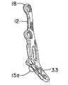
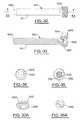
- FIG. 1is a top view of the distal radial plate and plate head in accordance with a first embodiment of the invention
- FIG. 2is a perspective view of the plate of FIG. 1 viewed from the outer proximal surface looking toward the head with the styloid side of the plate downward;
- FIG. 3is a cross section of the plate of FIG. 1 taken along line 3 - 3 in FIG. 1 ;
- FIG. 3Ais a detailed view of the central screw hole of FIG. 3 ;
- FIG. 4is a cross section of the plate of FIG. 3 taken along line 4 - 4 in FIG. 3 ;
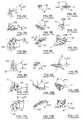
- FIG. 5Ais a detail of the head of the distal radial plate of FIG. 1 showing the angle of the axis of the screw for hole 1 in the XY plane;
- FIG. 5Bis a detail of the head of the distal radial plate of FIG. 1 showing the angle of the axis of the screw for hole 1 in the XZ plane;
- FIG. 5Cis a detail of the head of the distal radial plate of FIG. 1 showing the angle of the axis of the screw for hole 1 in the YZ plane;
- FIG. 6Ais a detail of the head of the distal radial plate of FIG. 1 showing the angle of the axis of the screw for hole 2 and hole K 2 in the XY plane;
- FIG. 6Bis a detail of the head of the distal radial plate of FIG. 1 showing the angle of the axis of the screw for hole 2 and hole K 2 in the XZ plane;
- FIG. 6Cis a detail of the head of the distal radial plate of FIG. 1 showing the angle of the axis of the screw for hole 2 and hole K 2 in the YZ plane;
- FIG. 7Ais a detail of the head of the distal radial plate of FIG. 1 showing the angle of the axis of the screw for hole 3 and hole K 3 in the XY plane;
- FIG. 7Bis a detail of the head of the distal radial plate of FIG. 1 showing the angle of the axis of the screw for hole 3 and hole K 3 in the XZ plane;
- FIG. 7Cis a detail of the head of the distal radial plate of FIG. 1 showing the angle of the axis of the screw for hole 3 and hole K 3 in the YZ plane;
- FIG. 8Ais a detail of the head of the distal radial plate of FIG. 1 showing the angle of the axis of the screw for hole 4 in the XY plane;
- FIG. 8Bis a detail of the head of the distal radial plate of FIG. 1 showing the angle of the axis of the screw for hole 4 in the XZ plane;
- FIG. 8Cis a detail of the head of the distal radial plate of FIG. 1 showing the angle of the axis of the screw for hole 4 in the YZ plane;
- FIG. 9Ais a detail of the head of the distal radial plate of FIG. 1 showing the angle of the axis of the screw for hole 5 and hole K 5 in the XY plane;
- FIG. 9Bis a detail of the head of the distal radial plate of FIG. 1 showing the angle of the axis of the screw for hole 5 and hole K 5 in the XZ plane;
- FIG. 9Cis a detail of the head of the distal radial plate of FIG. 1 showing the angle of the axis of the screw for hole 5 and hole K 5 in the YZ plane;
- FIG. 10Ais a detail of the head of the distal radial plate of FIG. 1 showing the angle of the axis of the screw for hole 6 in the XY plane;
- FIG. 10Bis a detail of the head of the distal radial plate of FIG. 1 showing the angle of the axis of the screw for hole 6 in the XZ plane;
- FIG. 10Cis a detail of the head of the distal radial plate of FIG. 1 showing the angle of the axis of the screw for hole 6 in the YZ plane;
- FIG. 11Ais a detail of the head of the distal radial plate of FIG. 1 showing the angle of the axis of the screw for hole 7 and hole K 7 in the XY plane;
- FIG. 11Bis a detail of the head of the distal radial plate of FIG. 1 showing the angle of the axis of the screw for hole 7 and hole K 7 in the XZ plane;
- FIG. 11Cis a detail of the head of the distal radial plate of FIG. 1 showing the angle of the axis of the screw for hole 7 and hole K 7 in the YZ plane;
- FIG. 12is a view taken from the radial styloid side edge of the plate of FIG. 1 ;
- FIG. 13is a view taken from the proximal edge of the plate of FIG. 1 ;
- FIG. 14is a section of the plate taken along line 14 - 14 of FIG. 1 ;
- FIG. 14Ais a detail of the screw hole of FIG. 14 ;
- FIG. 15is a view from the side of the lunate prominence with the plate head in a lowered orientation and viewing the head in partial section to illustrate the detail of the threads of the peg holes;
- FIG. 15Ais a detail of the peg holes from FIG. 15 ;
- FIG. 16is a top view of the plate of FIG. 1 showing the lines at which the lateral sections of FIGS. 16A through 16G ;
- FIG. 16Ais a section in the Y direction taken at line 16 a of FIG. 16 ;
- FIG. 16Bis a section in the Y direction taken at line 16 b of FIG. 16 ;
- FIG. 16Cis a section in the Y direction taken at line 16 c of FIG. 16 ;
- FIG. 16Dis a section in the Y direction taken at line 16 d of FIG. 16 ;
- FIG. 16Eis a section in the Y direction taken at line 16 e of FIG. 16 ;
- FIG. 16Fis a section in the Y direction taken at line 16 f of FIG. 16 ;
- FIG. 16Gis a section in the Y direction taken at line 16 g of FIG. 16 are taken;
- FIG. 17is a cross section of the plate of FIG. 1 taken at line 17 - 17 ;
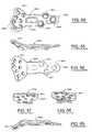
- FIG. 18is a top view of a second embodiment of the distal radius plate of the present invention.
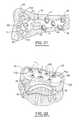
- FIG. 19is a view of the head of the distal radius plate of FIG. 18 with the locking cam inserts in position in the variable locking peg holes;
- FIG. 20is a top view of the plate of FIG. 18 with locking pegs, fixed pegs, and screws in position in the peg and screw holes of the plate;
- FIG. 21is a top view of the plate in accordance with the second embodiment of the invention in position on a radial bone;
- FIG. 22is a view from the proximal portion of the radial bone showing the plate in accordance with the present invention in position on the volar side of the bone and illustrating the angles for the pegs;
- FIG. 23is a top view of a third embodiment of the distal radial plate of the present invention with fixed angle pegs, and having an extended proximal portion;
- FIG. 24is a side perspective view of the embodiment of FIG. 23 ;
- FIG. 25is a top view of a fourth embodiment of the distal radial plate of the present invention with both fixed angle and variable angle locking pegs, and having an extended proximal portion;
- FIG. 26is a detail of the head of the distal radial plate of FIG. 25 showing the locking cam inserts in position in the peg holes of the head;
- FIG. 27is a side perspective view of the embodiment of FIG. 25 ;
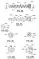
- FIG. 28is a side view of a locking screw that can be used as part of the plate system of the present invention.
- FIG. 29is a cross section of the locking screw of FIG. 28 taken along line 29 - 29 of FIG. 28 ;
- FIG. 29Ais a detail of the screw thread of FIG. 29 ;
- FIG. 29Bis a detail of the screw head of FIG. 29 ;
- FIG. 30is an end view of the insertion tip of the screw of FIG. 28 ;
- FIG. 31is an end view of the torque receiving recess of the head of the screw of FIG. 28 ;
- FIG. 32is a side view of a smooth locking peg that can be used as part of the plate system of the present invention.
- FIG. 33is a cross section of the smooth locking peg of FIG. 32 taken along line 33 - 33 of FIG. 32 ;
- FIG. 33Ais a detail of the locking thread of FIG. 32 ;
- FIG. 34is an end view of the insertion tip of the peg of FIG. 32 ;
- FIG. 35is an end view of the torque receiving recess of the head of the peg of FIG. 32 ;
- FIG. 36is a side view of a smooth variable angle locking peg that can be used as part of the plate system of the present invention.
- FIG. 37is a cross section of the smooth variable locking peg of FIG. 36 taken along line 37 of FIG. 36 ;
- FIG. 38is an end view of the insertion tip of the peg of FIG. 36 ;
- FIG. 39is an end view of the torque receiving recess of the head of the peg of FIG. 36 ;
- FIG. 40is a top view of the locking cam insert which can be used with the plate system of the present invention having the variable locking aspect of the invention
- FIG. 40Ais a detail of the stop pin from FIG. 40 ;
- FIG. 41is a cross section of the locking cam insert of FIG. 40 taken along line 40 - 40 ;
- FIG. 42is a cross section of the locking cam insert of FIG. 40 taken along line 42 - 42 in FIG. 41 ;
- FIG. 43is a side view of the locking cam insert of FIG. 40 showing the cam raceway in phantom;
- FIG. 44is a top view of the plate in accordance with the present invention with the locking cam insert in position, and showing the stop recess in the plate in phantom;
- FIG. 45is a side view of a threaded variable axis locking peg that can be used as part of the plate system of the present invention.
- FIG. 46is a cross section of the threaded variable peg of FIG. 45 taken along line 46 - 46 of FIG. 45 ;
- FIG. 46 ais a detail of the thread of FIG. 45 ;
- FIG. 47is an end view of the insertion tip of the peg of FIG. 45 ;
- FIG. 48is an end view of the torque receiving recess of the head of the peg of FIG. 45 ;
- FIG. 49is a side view of a non-locking screw that can be used as part of the plate system of the present invention.
- FIG. 50is a cross section of the non-locking screw of FIG. 49 taken along line 50 - 50 of FIG. 49 ;
- FIG. 50Ais a detail of the thread of FIG. 50 ;
- FIG. 51is an end view of the insertion tip of the screw of FIG. 49 ;
- FIG. 52is an end view of the torque receiving recess of the head of the screw of FIG. 49 ;
- FIG. 53is a top perspective view of a drill guide that can be used with the plate system of the present invention.
- FIG. 54is a top view of a short version of the orthopedic plate in accordance with the present invention.
- FIG. 55is a first side view of the plate of FIG. 54 ;
- FIG. 56is a bottom view of the plate of FIG. 54 ;
- FIG. 57is an edge view from the distal edge of the plate of FIG. 54 ;
- FIG. 58is a edge view from the proximal edge of the plate of FIG. 54 ;
- FIG. 59is a second side view of the plate of FIG. 54 .
- the present inventionrelates to an orthopedic plate that can be used to stabilize the fracture of a radial bone.
- a first embodiment of the plateis shown generally at 10 in FIG. 1 which includes a first, most distal portion or head 11 which has a profile from the top view similar to the palm of a hand, or which is shaped like a truncated heart, or a modified kidney shape.
- the head 11slopes upward in a complex and organic topography away from the more elongated inversely curving proximal portion 12 of the plate.
- the head 11includes a plurality of holes 13 for pegs, which holes can be internally threaded or not, or can also include means to provide for a variable locking axis.
- the proximal plate portion 12also includes a plurality of holes 14 for screws, which similarly can include internal threads, or be smooth, or include means for a variable locking axis screw.
- the proximal portion of the platealso includes a slot 15 which is situated near the junction of the head 11 and the proximal portion of the plate, or the neck 16 .
- the slot 15can have a smooth internal edge, or can include a textured feature, such as grooves or tracks.
- the proximal portionalso has two sets of tabs or ears, an intermediate pair 17 and a terminal pair 18 which each extend laterally from the longitudinal profile of the plate, and which provide for opposing screw holes that are each offset from the longitudinal axis of the plate and from each other along the longitudinal axis.
- the central point of a central screw hole 19provides a point of reference or origin for mapping in three dimensions the topography or superficial locus of any point on the plate, which in turn enables the plate to be made having the complex curving fully contoured configuration that it does.
- the offset earsprovide for convergence of the screws in the proximal or plate portion 12 of the distal radius plate while still avoiding screw interference, while providing for improved pullout strength as compared to a version where the proximal screws are located along a line, such as the longitudinal axis.
- the edge of the platemay be planar, and so may be surface features, such as an edge about a bore or “counterbore”.
- the bone facing or contacting surface of the plateis designed to correspond to the surface of an idealized bone that represents a generalization of a collection of bones.
- the platehas a lower surface which is substantially free from planes (again meaning that there are no planar surfaces of a size that would defeat the correspondence of the plate with the intended bone site.
- the head portion 11 of the platehas a complex profile which is rounded on either side away from the neck area 16 to form a first prominence 21 and a second prominence 23 .
- the first prominence 21has a more gradual curve than the second prominence and is also the more distally extending of the two prominences. It is intended to support the radial styloid, and thus is termed the styloid prominence herein.
- the plateis provided in a left and a right version, which are mirror images of each other.
- the plateis generally intended to be implanted on the volar side of the radius (i.e. the top side when the arm is supine, and the palm is pointed upward).
- the styloid prominence 21is thus on the lateral facing side of the plate, or the thumbward side.
- the second prominence 23is designed to fit under the ridge of the lunate process, and is thus termed the “lunate” prominence herein.
- the distal edge 22 of the head 11extends in a direction across the longitudinal axis of the proximal portion of the plate in three segments.
- a first portion 25extends substantially transverse to the longitudinal axis of the plate to a point slightly more than, or about midway across the head of the plate.
- a second edge portion 27links the first portion 25 and the third portion 29 and extends at an oblique angle proximally toward the third edge portion. The edge portion 27 or oblique link helps the surgeon to gauge the placement of the plate relative to the lunate ridge of the radial bone.
- the cross sectional dimensionis generally sufficiently uniform that the contours of the top surface 30 generally mirror the contours of the bottom surface 31 .
- “bottom”is used to mean the surface which faces, and which may, but does not necessarily have to touch the bone
- “top”means the outwardly facing surface. These surfaces undulate to mimic the shape or topography of the radial bone.
- the bottom surface of the proximal portion of the plateincludes a concavity or radius 32 along the longitudinal axis where the thumb side of the plate has a greater arc than the pinky side. As might best be viewed in FIG.
- the pinky side of the plate(i.e., in that view, the right side) forms a shallow serpentine on both the top and bottom surfaces which defines a gentle depression or cup 33 which is followed by a rise toward the lunate prominence 23 of the head.
- the cupextends and becomes shallower as the plate surface rises toward the styloid prominence, which has the highest elevation in the Z direction.
- FIG. 13further illustrates this aspect of the plate in accordance with the invention where the X axis is taken through a central screw hole.
- FIGS. 16 through 16Grepresent parallel slices taken in the Z planes at progressive locations along the longitudinal axis. It can be seen from these sections that the head portion 11 of the plate, as well as the proximal portion 12 of the plate is substantially non-planar, meaning that there is no significant portion of either the top surface or the bottom surface of either the head portion, or the proximal portion that defines a single plane. Instead, the head of the plate undulates from a central cup area that has a diagonal aspect from its lowest portion near the neck 16 of the plate on the pinky side of the head to the highest portion at the distal area on the styloid side of the plate.
- the platehas a depression 33 in the top side of the head which extends diagonally in the direction from the styloid prominence 21 toward the necked area 16 under the lunate prominence 23 .
- the top or exterior surface of the head 11has a slightly concave area or cupped area 33 and other areas, such as the styloid prominence 21 and the lunate prominence 23 which are slightly convex on the top surface 30 , or which rise. This transition can be said to cause the head to have top and bottom surfaces 30 , 31 which undulate as they transition from the proximal portion of the plate 12 to the head portion 11 .
- the proximal portion of the plate 12includes a bottom surface 31 which is radiused to fit the curve of the bone as it extends proximally from the wrist joint toward the elbow joint.
- This concave, or radiused areachanges as it extends along the longitudinal axis of the plate.
- the platetransitions from an area that is flatter in the vicinity of the neck 16 , and which increases in the amount of curve as can be seen by comparing FIG. 16D through 16G which illustrate the cross-section of the plate at progressive proximal locations along the longitudinal axis.
- the cross section of the head 11is illustrated in FIGS. 16A through 16C which shows the plate at progressive distal locations along the longitudinal axis of the plate.
- the plate head 11is further provided with a plurality of holes 40 which receive pegs that are implanted into the distal portion of the radius, or into fragments of the bone.
- the distal radius plate head of the present inventionis presented in two embodiments.
- all of the holesdefine a fixed axis for the pegs which they receive.
- the pegs holes 40include internal threads 41 which mate with locking threads on the head of the pegs and which therefore lock the pegs in position in the plate.
- the platecould include peg holes which have no internal threads, or some combination of threaded and non-threaded holes.
- pegscan be used with a plate having threaded holes, where the pegs are not threaded at the top, but include a head that fits within the major diameter of the internal threads.
- the pegsmay be locking pegs which have threads that mate with threads in the holes, or may be free from threads at the head.
- the pegsmay be threaded or non-threaded at the shaft portion.
- the use of the term “pegs”may encompass screws and vice versa.
- the holesinclude a distal hole 42 in the styloid prominence 21 , and a hole in the lunate prominence 45 and one or more (two in the case shown) holes 43 , 44 in the head intermediate to the two side holes.
- One or more proximal set of holesis also advantageously provided.
- a hole 46may be provided under the styloid hole 42 and a hole 48 may be provided proximal to the hole 45 in the lunate prominence 23 , and a hole 47 may be provided between the hole 46 and the hole 48 .
- the angles of these holesdetermine the angles of the pegs that they receive. The angles are defined on a three coordinate matrix where 0,0,0 is the origin and is located at the center of a central screw hole in the plate. FIGS.
- the plate 5 a through 8 cdefines the angles for each of the three axes for the holes.
- the plateis shown as including smaller diameter holes for K wires which help with the placement and angulation of the pegs.
- the holes K 43 -K 48have similar orientations to the holes 43 - 48 (where no K holes are illustrated for holes 42 , 45 and 47 ).
- the anglesare set to provide for the most common dislocation of fragments and to provide for the optimal fixation using the pegs.
- the designcontemplates a plurality of fixed peg holes, including one 42 , 45 in each of the styloid (i.e. hole one) and lunate prominences (i.e. hole four), which splay outward and away from the plate such that they diverge away from one another to be capable of locking a styloid fragment and/or a fragment from the lunate fossa portion of the radial bone.
- a second distal-most hole 43is located generally under the skewed linking area of the head, which defines a peg axis that extends through the radius and distally toward the scaphoid or navicular bone and a third hole 44 is distally aligned between the two holes of the prominences but is slightly backed off proximally from the second hole, with a peg axis that is more transverse than the peg axis of the second hole.
- the fourth peg hole 45is the hole of the lunate prominence which is slightly more proximal than the first hole which is located in the styloid prominence.
- a fifth hole 46is located in the first rounded side, which is on the styloid or thumbward side, toward the intersection between the proximal portion of the plate, and the plate head.
- the axis defined by this holediverges outwardly toward the lateral portion of the radius (in a supine position).
- a sixth hole 47is located in a central portion of the head such as on a longitudinal axis of the plate, and a final seventh hole 48 is located most proximally at the intersection of the head 11 and the proximal portion of the plate 12 at the neck 16 of the plate, with the axis of the peg appearing to be more or less transverse relative to the plane defined by the opening of the peg hole.
- pegsare included which have a variable axis with a locking mechanism. It is particularly preferred that the plate include the fixed and variable axis type of pegs.
- FIGS. 18 through 22 , and 25 through 27illustrate this second embodiment of the invention.
- one or more of the peg holes in the head portion 111 of the plate 110 of the first embodimentmay be replaced with variable locking pegs, or the pegs may be reoriented.
- the proximal portion 112has the same features and is the same as previously described.
- holes 42 , 45 , and 47are each replaced with a variable locking mechanism 142 , 145 , and 147 .
- the mechanismincludes a camming mechanism on the head of the peg which mates with a cam locking insert that fits into and locks into a hole in the plate.
- the cam locking insertincludes an anchor member that causes the cam locking insert to resist rotation as the camming members of the peg engage the cam raceway of the cam locking insert. This mechanism is described in greater detail hereinafter.
- a distal radius platewhich has an elongated proximal portion.
- This designis illustrated in FIGS. 23 through 27 and is shown with a distal head having only fixed angle pegs and having both fixed and variable angle pegs.
- the plate 310has a distal portion, or head 311 and a proximal portion 312 .
- the head portionincludes pegs holes 313 which can be internally threaded so as to define screw holes having fixed axes as is shown in FIGS. 23 and 24 , or as is illustrated in FIGS. 25 , 26 and 27 , one or more of the fixed peg holes may be replaced with a variable axis mechanism, that advantageously also provides for locking of the angle of the axis.
- the elongated version of the plateincludes the features of the previously described version, with screw holes 314 in the proximal portion; an elongated slot 315 located along the central axis of the plate, adjacent the neck 316 which is the area that links the head 311 , and the proximal portion 312 .
- the elongated version of the platefurther includes an intermediate tabbed area 317 having opposing offset ears that each receive a screw through an internally threaded screw hole, and a terminal tabbed area 318 that includes opposing offset ears that likewise each includes internally threaded screw holes.
- This version of the plateincludes a central screw hole 319 that defines the origin for the coordinate system of the plate, and in addition, there are one or more additional longitudinally aligned screw holes 320 .
- the elongated version of the platehas a proximal portion having a spiraling radiused portion similar to the shorter version except with a longer, and thus, more pronounced spiral, as can be seen in FIGS. 24 and 27 .
- the fixed angle head 311is the same as for the shorter version and the fixed angle head 11 of FIG. 1
- the head 411 shown in FIGS. 25-27is the same as the head 111 shown in FIG. 18 .
- FIGS. 28 through 31shows a locking screw which can be used in the head of the distal radius plate of the present invention.
- these screws 510include a threaded shaft portion 511 , and a threaded head 520 .
- the shaft 511has a minor diameter 512 about which the thread 513 spirals.
- the thread 513includes a spiraling radial edge 514 best viewed in the thread detail FIG. 29 a , which defines the major diameter.
- the threadfurther includes a front thrust face 515 which forms an angle of about 20°+/ ⁇ 5° to a plane transverse to the longitudinal axis of the screw.
- the trailing face 516 of the thread 513forms an angle of about 5°+/ ⁇ 2° to the same plane.
- the head of the screw 520includes external locking threads 523 as can be best viewed in the head detail in FIG. 29 b . These threads also include a radial edge 524 , a front thrust face 525 , and a trailing face 526 .
- the angle of the front thrust face 525is the same as the angle of the trailing face relative to a plane which transverses the longitudinal axis of the screw, and is about 30°+/ ⁇ 5° for each angle.
- the locking thread 523 on the head 520 of the screwis a symmetrical v-shaped thread when viewed in profile in cross section.
- the head 520tapers along the longitudinal axis, in both the major and the minor diameter, by a similar amount, as is shown in FIG. 29 b .
- the taperis 7°, or 3.5° per side when measured in cross-section.
- the larger screwis 20° or 10° per side in section.
- the headfurther includes a torque driving recess 530 which has a suitable shape to receive a torque driver. This is shown in FIGS. 29 b and 31 .
- the shape shownis a modified six lobed sinusoidal curve.
- the recessincludes a central cylindrical bore 532 which receives the terminal post of a screwdriver to retain the screw on the driver.
- a transitional area 533is angles to connect the recess 530 and the bore 532 .
- the insertion tip 540 of the screwis blunt and preferably forms a portion of a sphere.
- FIGS. 33 through 35illustrate a distal locking peg 610 which is similar to the locking screws shown in FIGS. 29 through 31 , except that the shaft of the peg 611 is not threaded.
- the head 620however, includes locking threads 623 as previously described for the locking screw, and a torque driving recess 630 as previously described.
- the pegsfurther include a blunt or rounded insertion tip 640 .
- FIGS. 36 through 39shows a peg which can be used with the variable locking mechanism for the present invention.
- the peg 650has a smooth shaft 651 with a rounded or blunt insertion tip 690 .
- the shaftis connected by a neck area 652 to a locking head 670 which may include a torque driving recess 680 with a bore 682 both as previously described to provide for an interference fit with the post of a torque driver so that the peg is self-retained.
- the head 670also includes a pair of wings 672 which act to engage the cam raceways in the cam insert 710 shown in FIGS. 40 through 43 . While the camming mechanism is shown as including only two wings, it should be understood that the head could include more wings, and specifically three or four.
- the wingsextend from about 40° to about 50° and spiral slightly from the base 673 of the head 670 upward toward the top surface 675 .
- the baseis slightly rounded.
- the wingshave a quadrilateral cross section as can be seen in FIG
- the camming insertis a generally circular or ring shaped insert 710 having an expansion gap 712 which is essentially a planar slice taken in the insert so as to create a gap.
- the insert 710has a top surface 714 which is generally planar joined to a co-planar bottom surface 716 by an outwardly curving side surface 718 .
- the groovesare open, and preferably only for a portion of the top 714 where the grooves are located. This open area of the race allows the cams to be introduced into the race.
- the camengages the cam race and causes the insert to expand at the gap. This action causes the insert to lock in the recess 726 in the plate which receives the insert.
- the insert 712includes a stop 724 .
- the stopis a projection that is received in a well 728 in the recess which retains the stop 724 and prohibits the cam insert from turning with the peg as it is turned relative to the plate.
- FIGS. 45 through 48show a variable axis locking screw 750 which is similar to the variable axis locking peg shown in FIGS. 36 through 39 and has a shaft 751 with a blunt or rounded insertion tip 790 .
- the shaft 751tapers throughout its length so that the screw 750 does not include a linking neck area as the peg does.
- the screwdoes include a locking head 760 .
- the locking headincludes a pair of cam wings 770 which are shaped as for the locking peg and which engage the race in the locking insert 710 in the same way as the cam wings of the variable locking peg.
- the shaft of the variable locking screw 750is threaded with a thread 753 that is similar to the screw thread of the locking screw as shown and described for FIGS.
- the head 760further includes a torque driving recess 780 with an optional bore 782 connected to the torque driving recess by a transitional area 781 which retains the screw 750 on the post of a screwdriver.
- FIGS. 49 through 52illustrate a proximal non-locking proximal screw 810 which is intended in particular for use in the proximal portion of the plate when it is desirable that the screw does not lock into the plate.
- the screw 810has a shaft portion 811 having a thread 813 similar to the thread previously described for FIGS. 29 through 31 .
- the thread 813 shown in FIGS. 49 through 52has a taper in the minor diameter 812 over a portion 815 of the shaft 811 , such as the first three turns of the thread. Thereafter, the terminal portion 816 of the shaft 811 has a constant minor diameter 812 .
- the screw 810has a blunt tip 850 and a rounded head 820 having a torque driving recess 830 optionally including a bore 832 to receive the post of a screwdriver to retain the screw on the screwdriver.
- the headhas a spherically rounded lower portion 834 and a rounded upper portion 836 where the maximum outer diameter is smaller than the inner diameter of the threaded proximal screw holes.
- FIG. 53shows a drill guide for either the holes in the distal portion or for the holes in the proximal portion.
- the drill guide 910includes an extending handle 912 with a tapering linking portion 914 and a post 916 which engages the hole in the plate.
- the post 916has an internal hole for the drill bit and can have a smooth tapered surface at the terminal end 918 which engages the hole of the plate by friction, or the post end 918 can include threads to lock into the internal threads of the plate and to fix the angle for the fixed screws.
- FIGS. 29 through 34show a further embodiment of the plate in accordance with the invention. This plate 1010 is comparable to the other embodiments in having a head 1011 joined to a proximal plate portion 1012 .
- the head 1011includes a plurality of peg holes 1013 as previously described and the proximal portion includes a plurality of screw holes 1014 .
- This embodiment of the platehas only a single set of offset tabs 1017 which allows for convergent screws and the plate ends in a terminus 1018 .
- FIGS. 54 through 59show a further embodiment of the plate in accordance with the invention.
- This plate 1610is comparable to the other embodiments in having a head 1611 joined to a proximal plate portion 1612 .
- the head 1611includes a plurality of peg holes 1613 as previously described and the proximal portion includes a plurality of screw holes 1614 .
- This embodiment of the platehas only a single set of offset tabs 1617 which allows for convergent screws and the plate ends in a terminus 1618 .
Landscapes
- Health & Medical Sciences (AREA)
- Orthopedic Medicine & Surgery (AREA)
- Surgery (AREA)
- Life Sciences & Earth Sciences (AREA)
- Heart & Thoracic Surgery (AREA)
- Nuclear Medicine, Radiotherapy & Molecular Imaging (AREA)
- Engineering & Computer Science (AREA)
- Biomedical Technology (AREA)
- Neurology (AREA)
- Medical Informatics (AREA)
- Molecular Biology (AREA)
- Animal Behavior & Ethology (AREA)
- General Health & Medical Sciences (AREA)
- Public Health (AREA)
- Veterinary Medicine (AREA)
- Surgical Instruments (AREA)
Abstract
Description
Claims (23)
Priority Applications (1)
| Application Number | Priority Date | Filing Date | Title |
|---|---|---|---|
| US11/713,856US8021402B2 (en) | 2006-03-07 | 2007-03-05 | Distal radius plate |
Applications Claiming Priority (2)
| Application Number | Priority Date | Filing Date | Title |
|---|---|---|---|
| US77986506P | 2006-03-07 | 2006-03-07 | |
| US11/713,856US8021402B2 (en) | 2006-03-07 | 2007-03-05 | Distal radius plate |
Publications (2)
| Publication Number | Publication Date |
|---|---|
| US20070265629A1 US20070265629A1 (en) | 2007-11-15 |
| US8021402B2true US8021402B2 (en) | 2011-09-20 |
Family
ID=38475504
Family Applications (1)
| Application Number | Title | Priority Date | Filing Date |
|---|---|---|---|
| US11/713,856Active2030-06-09US8021402B2 (en) | 2006-03-07 | 2007-03-05 | Distal radius plate |
Country Status (6)
| Country | Link |
|---|---|
| US (1) | US8021402B2 (en) |
| EP (1) | EP1993456A2 (en) |
| AU (1) | AU2007223991A1 (en) |
| BR (1) | BRPI0708679A2 (en) |
| CA (1) | CA2645022A1 (en) |
| WO (1) | WO2007103376A2 (en) |
Cited By (18)
| Publication number | Priority date | Publication date | Assignee | Title |
|---|---|---|---|---|
| USD662205S1 (en)* | 2011-07-13 | 2012-06-19 | Shoulder Options, Inc. | Suture anchor |
| WO2013152182A1 (en) | 2012-04-05 | 2013-10-10 | Orthohelix Surgical Designs, Inc. | Lateral ankle fusion plate system and jig, and method for use therewith |
| US20140148859A1 (en)* | 2012-11-27 | 2014-05-29 | Solana Surgical, Llc | Orthopedic fusion plate and compression screw |
| US8790378B2 (en) | 2012-02-02 | 2014-07-29 | Biomet C.V. | Distal radius fracture fixation plate with integrated and adjustable volar ulnar facet support |
| WO2014145190A1 (en)* | 2013-03-15 | 2014-09-18 | Gonzalez-Hernadez Eduardo | Bone fixation and reduction apparatus and method for fixation and reduction of a distal bone fracture and malunion |
| US9254154B2 (en) | 2011-03-03 | 2016-02-09 | Toby Orthopaedic, Inc. | Anterior lesser tuberosity fixed angle fixation device and method of use associated therewith |
| US9271776B2 (en) | 2010-10-05 | 2016-03-01 | Toby Orthopaedics, Inc. | System and method for facilitating repair and reattachment of comminuted bone portions |
| US9283008B2 (en) | 2012-12-17 | 2016-03-15 | Toby Orthopaedics, Inc. | Bone plate for plate osteosynthesis and method for use thereof |
| US9402667B2 (en) | 2011-11-09 | 2016-08-02 | Eduardo Gonzalez-Hernandez | Apparatus and method for use of the apparatus for fracture fixation of the distal humerus |
| US9451992B2 (en)* | 2010-12-01 | 2016-09-27 | Facet-Link Inc. | Variable angle bone screw fixation arrangement |
| US9468479B2 (en) | 2013-09-06 | 2016-10-18 | Cardinal Health 247, Inc. | Bone plate |
| US9649141B2 (en) | 2010-05-07 | 2017-05-16 | Mcginley Engineered Solutions, Llc | System for treating bone fractures |
| US9730797B2 (en) | 2011-10-27 | 2017-08-15 | Toby Orthopaedics, Inc. | Bone joint replacement and repair assembly and method of repairing and replacing a bone joint |
| US9730686B2 (en) | 2014-09-03 | 2017-08-15 | Biomet C.V. | System and method of soft tissue anchoring to metaphyseal bone plate |
| US9757240B2 (en) | 2010-10-27 | 2017-09-12 | Toby Orthopaedics, Inc. | System and method for fracture replacement of comminuted bone fractures or portions thereof adjacent bone joints |
| US9833270B2 (en) | 2013-09-19 | 2017-12-05 | Mcginley Engineered Solutions, Llc | Variable angle blade plate system and method |
| US20180235663A1 (en)* | 2015-08-26 | 2018-08-23 | J&L Medical Technology Co., Ltd. | External fixing device for treating a fracture of calcaneal |
| US10188522B2 (en) | 2011-10-27 | 2019-01-29 | Toby Orthopaedics, Inc. | System for replacement of at least a portion of a carpal articular surface of a radius |
Families Citing this family (20)
| Publication number | Priority date | Publication date | Assignee | Title |
|---|---|---|---|---|
| FR2920960B1 (en)* | 2007-09-17 | 2010-09-17 | Small Bone Innovations Interna | OSTEOSYNTHESIS PLATE FOR FRACTURE OF THE LOWER END OF RADIUS |
| US8343228B2 (en)* | 2008-09-03 | 2013-01-01 | The Cleveland Clinic Foundation | Arthroplastic implant with anchor peg for basilar joint and related methods |
| US8231625B2 (en)* | 2008-09-03 | 2012-07-31 | The Cleveland Clinic Foundation | Modular bone fixation device for treatment of fractures and related methods |
| US8506641B2 (en)* | 2008-09-03 | 2013-08-13 | The Cleveland Clinic Foundation | Arthrodesis implant for finger joints and related methods |
| US8167952B2 (en)* | 2008-09-03 | 2012-05-01 | The Cleveland Clinic Foundation | Arthroplastic implant with shield for basilar joint and related methods |
| US8828063B2 (en) | 2008-11-19 | 2014-09-09 | Amei Technologies, Inc. | Fixation plate for use in the Lapidus approach |
| US20120016366A1 (en)* | 2009-04-08 | 2012-01-19 | Eglseder W Andrew | Proximal Radius Locking Plate |
| US10390867B2 (en) | 2009-09-18 | 2019-08-27 | Biomet C.V. | Bone plate system and method |
| WO2011035103A2 (en)* | 2009-09-18 | 2011-03-24 | Depuy Products, Inc. | Disposable orthopaedic surgery kit and components |
| JP2013512042A (en)* | 2009-11-27 | 2013-04-11 | シンセス ゲゼルシャフト ミット ベシュレンクテル ハフツング | Planar fixation concept for distal radius fractures |
| FR2956971B1 (en) | 2010-03-08 | 2012-03-02 | Memometal Technologies | PLATE OSTEOSYNTHESIS SYSTEM |
| FR2956972B1 (en) | 2010-03-08 | 2012-12-28 | Memometal Technologies | ARTICULATED OSTEOSYNTHESIS PLATE |
| WO2012050424A1 (en)* | 2010-10-14 | 2012-04-19 | Sai Yeong Leong | A distal radius plating system |
| US9579133B2 (en) | 2013-02-01 | 2017-02-28 | James Guthlein | Internal fixation device |
| FR3006163B1 (en) | 2013-05-29 | 2016-03-25 | Fx Solutions | HUMERAL PLATE |
| PL3416575T3 (en)* | 2016-02-19 | 2020-06-01 | 41Medical Ag | Device for bone fixation |
| BR112017021208A2 (en) | 2016-10-05 | 2018-08-07 | Wright Medical Technology, Inc. | implant system and method |
| EP3530224A1 (en)* | 2018-02-23 | 2019-08-28 | Medartis Holding AG | Wrist arthrodesis plate |
| WO2021087627A1 (en)* | 2019-11-07 | 2021-05-14 | Bonebridge Ag | Fracture fixation plate |
| WO2025111338A1 (en)* | 2023-11-20 | 2025-05-30 | Arthrex, Inc. | Veterinary ilial fracture plates |
Citations (44)
| Publication number | Priority date | Publication date | Assignee | Title |
|---|---|---|---|---|
| US3741205A (en)* | 1971-06-14 | 1973-06-26 | K Markolf | Bone fixation plate |
| US4388921A (en)* | 1980-05-28 | 1983-06-21 | Institut Straumann Ag | Device comprising a plate and screws for fastening a plate to a bone |
| US4573458A (en)* | 1982-08-17 | 1986-03-04 | Zimmer, Inc. | Bone fixation plate |
| US4988350A (en)* | 1988-06-24 | 1991-01-29 | Wolfgang Herzberg | Device for reconnecting a broken bone |
| US5015248A (en)* | 1990-06-11 | 1991-05-14 | New York Society For The Relief Of The Ruptured & Crippled, Maintaining The Hospital For Special Surgery | Bone fracture fixation device |
| US5197966A (en) | 1992-05-22 | 1993-03-30 | Sommerkamp T Greg | Radiodorsal buttress blade plate implant for repairing distal radius fractures |
| US5531746A (en)* | 1995-04-13 | 1996-07-02 | Fastenetix, L.L.C. | Posterior spinal polyaxial locking lateral mass screw plate assembly |
| US5586985A (en)* | 1994-10-26 | 1996-12-24 | Regents Of The University Of Minnesota | Method and apparatus for fixation of distal radius fractures |
| US5728099A (en)* | 1994-02-21 | 1998-03-17 | Collux A.B. | Implant |
| US5749872A (en)* | 1995-09-08 | 1998-05-12 | Ace Medical Company | Keyed/keyless barrel for bone plates |
| US6096040A (en)* | 1996-06-14 | 2000-08-01 | Depuy Ace Medical Company | Upper extremity bone plates |
| US6221073B1 (en)* | 1999-08-20 | 2001-04-24 | Kinetikos Medical, Inc. | Wrist fusion apparatus and method |
| US6235032B1 (en)* | 1996-08-22 | 2001-05-22 | Waldemar Link (Gmbh & Co) | Calcaneal bone plate |
| USD443060S1 (en)* | 2000-06-01 | 2001-05-29 | Bristol-Myers Squibb Company | Bone plate |
| US20020013587A1 (en)* | 1998-03-31 | 2002-01-31 | Robert A. Winquist | Orthopaedic bone plate |
| US6358250B1 (en) | 2000-02-01 | 2002-03-19 | Hand Innovations, Inc. | Volar fixation system |
| US20020156474A1 (en)* | 2001-04-20 | 2002-10-24 | Michael Wack | Polyaxial locking plate |
| US6488685B1 (en)* | 1995-06-26 | 2002-12-03 | Easton L. Manderson | Extramedullary rod fixateur for bones |
| US6508819B1 (en) | 2001-08-28 | 2003-01-21 | Hand Innovations, Inc. | Method of dorsal wrist fracture fixation |
| US20030105461A1 (en)* | 2001-11-30 | 2003-06-05 | Putnam Matthew D. | Wrist surgery devices and techniques |
| US20030114856A1 (en)* | 2001-12-14 | 2003-06-19 | Nathanson Jeremy J. | Internal osteotomy fixation device |
| US6623486B1 (en) | 1999-09-13 | 2003-09-23 | Synthes (U.S.A.) | bone plating system |
| US6652530B2 (en)* | 2001-09-19 | 2003-11-25 | The University Of Hong Kong | Fixation device |
| US6712820B2 (en) | 2000-02-01 | 2004-03-30 | Hand Innovations, Inc. | Fixation plate system for dorsal wrist fracture fixation |
| US20040102778A1 (en)* | 2002-11-19 | 2004-05-27 | Huebner Randall J. | Adjustable bone plates |
| US20040153073A1 (en) | 2000-02-01 | 2004-08-05 | Hand Innovations, Inc. | Orthopedic fixation system including plate element with threaded holes having divergent axes |
| US20040167522A1 (en)* | 2001-05-28 | 2004-08-26 | Alfred Niederberger | Bone plate |
| US20040193155A1 (en) | 2003-03-27 | 2004-09-30 | Hand Innovations, Inc. | Fracture fixation plate with particular plate hole and fastener engagement and methods of using the same |
| US20050010226A1 (en)* | 2003-05-30 | 2005-01-13 | Grady Mark P. | Bone plate |
| US20050049594A1 (en)* | 2001-04-20 | 2005-03-03 | Wack Michael A. | Dual locking plate and associated method |
| US20050065522A1 (en) | 2003-03-27 | 2005-03-24 | Orbay Jorge L. | Low profile distal radius fracture fixation plate |
| US20050085818A1 (en) | 2003-10-17 | 2005-04-21 | Huebner Randall J. | Systems for distal radius fixation |
| US20050240187A1 (en)* | 2004-04-22 | 2005-10-27 | Huebner Randall J | Expanded fixation of bones |
| US20060173458A1 (en)* | 2004-10-07 | 2006-08-03 | Micah Forstein | Bone fracture fixation system |
| US20060241608A1 (en)* | 2005-03-31 | 2006-10-26 | Mark Myerson | Plate for fusion of the metatarso-phalangeal joint |
| US20060259039A1 (en) | 2005-05-06 | 2006-11-16 | Inion Oy | Plate system for securing bone or bone fragments |
| US20070088360A1 (en)* | 2005-09-19 | 2007-04-19 | Orbay Jorge L | Bone stabilization system including multi-directional threaded fixation element |
| US20070233106A1 (en)* | 2006-02-24 | 2007-10-04 | Synthes (Usa) | Tibal plateau leveling osteotomy plate |
| US7335204B2 (en)* | 2001-07-17 | 2008-02-26 | Tornier Sa | Osteosynthesis plate for the upper end of the arm bone |
| USD576731S1 (en)* | 2007-01-17 | 2008-09-09 | Orthohelix Surgical Designs, Inc. | Orthopedic plate |
| US20080275510A1 (en)* | 2007-05-03 | 2008-11-06 | Medartis Ag | Fixation Device, Combination of a Fixation Device with an Elongate Element, Arrangment with Such a Combination and Osteosynthesis Set |
| US20100125300A1 (en)* | 2008-11-19 | 2010-05-20 | Amei Technologies, Inc. | Fixation plate for use in the lapidus approach |
| US20100152783A1 (en)* | 2008-12-11 | 2010-06-17 | Veterinary Implants Direct, Llc | Universal Surgical Plate with 30 Degree Compression Angle |
| US20100305618A1 (en)* | 2005-01-28 | 2010-12-02 | Orthohelix Surgical Designs, Inc. | Orthopedic plate |
- 2007
- 2007-03-05USUS11/713,856patent/US8021402B2/enactiveActive
- 2007-03-06CACA002645022Apatent/CA2645022A1/ennot_activeAbandoned
- 2007-03-06WOPCT/US2007/005699patent/WO2007103376A2/enactiveApplication Filing
- 2007-03-06EPEP07752402Apatent/EP1993456A2/ennot_activeWithdrawn
- 2007-03-06AUAU2007223991Apatent/AU2007223991A1/ennot_activeAbandoned
- 2007-03-06BRBRPI0708679-2Apatent/BRPI0708679A2/ennot_activeIP Right Cessation
Patent Citations (52)
| Publication number | Priority date | Publication date | Assignee | Title |
|---|---|---|---|---|
| US3741205A (en)* | 1971-06-14 | 1973-06-26 | K Markolf | Bone fixation plate |
| US4388921A (en)* | 1980-05-28 | 1983-06-21 | Institut Straumann Ag | Device comprising a plate and screws for fastening a plate to a bone |
| US4573458A (en)* | 1982-08-17 | 1986-03-04 | Zimmer, Inc. | Bone fixation plate |
| US4988350A (en)* | 1988-06-24 | 1991-01-29 | Wolfgang Herzberg | Device for reconnecting a broken bone |
| US5015248A (en)* | 1990-06-11 | 1991-05-14 | New York Society For The Relief Of The Ruptured & Crippled, Maintaining The Hospital For Special Surgery | Bone fracture fixation device |
| US5197966A (en) | 1992-05-22 | 1993-03-30 | Sommerkamp T Greg | Radiodorsal buttress blade plate implant for repairing distal radius fractures |
| US5973223A (en)* | 1994-02-21 | 1999-10-26 | Collux Ab | Implant for fixing femoral fractures |
| US5728099A (en)* | 1994-02-21 | 1998-03-17 | Collux A.B. | Implant |
| US5586985A (en)* | 1994-10-26 | 1996-12-24 | Regents Of The University Of Minnesota | Method and apparatus for fixation of distal radius fractures |
| US5607426A (en)* | 1995-04-13 | 1997-03-04 | Fastenletix, L.L.C. | Threaded polyaxial locking screw plate assembly |
| US5876402A (en)* | 1995-04-13 | 1999-03-02 | Errico; Joseph P. | Anterior spinal polyaxial locking screw plate assembly having recessed retaining rings |
| US5531746A (en)* | 1995-04-13 | 1996-07-02 | Fastenetix, L.L.C. | Posterior spinal polyaxial locking lateral mass screw plate assembly |
| US6488685B1 (en)* | 1995-06-26 | 2002-12-03 | Easton L. Manderson | Extramedullary rod fixateur for bones |
| US5749872A (en)* | 1995-09-08 | 1998-05-12 | Ace Medical Company | Keyed/keyless barrel for bone plates |
| US6096040A (en)* | 1996-06-14 | 2000-08-01 | Depuy Ace Medical Company | Upper extremity bone plates |
| US6235032B1 (en)* | 1996-08-22 | 2001-05-22 | Waldemar Link (Gmbh & Co) | Calcaneal bone plate |
| US20020013587A1 (en)* | 1998-03-31 | 2002-01-31 | Robert A. Winquist | Orthopaedic bone plate |
| US6221073B1 (en)* | 1999-08-20 | 2001-04-24 | Kinetikos Medical, Inc. | Wrist fusion apparatus and method |
| US20040059334A1 (en) | 1999-09-13 | 2004-03-25 | Synthes (U.S.A.) | Bone plating system |
| US6623486B1 (en) | 1999-09-13 | 2003-09-23 | Synthes (U.S.A.) | bone plating system |
| US20050080421A1 (en) | 1999-09-13 | 2005-04-14 | Synthes (Usa) | Bone plating system |
| US20040153073A1 (en) | 2000-02-01 | 2004-08-05 | Hand Innovations, Inc. | Orthopedic fixation system including plate element with threaded holes having divergent axes |
| US6358250B1 (en) | 2000-02-01 | 2002-03-19 | Hand Innovations, Inc. | Volar fixation system |
| US6364882B1 (en) | 2000-02-01 | 2002-04-02 | Hand Innovations, Inc. | Volar fixation system |
| US20050245931A1 (en) | 2000-02-01 | 2005-11-03 | Orbay Jorge L | Volar fixation system |
| US6712820B2 (en) | 2000-02-01 | 2004-03-30 | Hand Innovations, Inc. | Fixation plate system for dorsal wrist fracture fixation |
| USD443060S1 (en)* | 2000-06-01 | 2001-05-29 | Bristol-Myers Squibb Company | Bone plate |
| US20020156474A1 (en)* | 2001-04-20 | 2002-10-24 | Michael Wack | Polyaxial locking plate |
| US20050049594A1 (en)* | 2001-04-20 | 2005-03-03 | Wack Michael A. | Dual locking plate and associated method |
| US20040167522A1 (en)* | 2001-05-28 | 2004-08-26 | Alfred Niederberger | Bone plate |
| US7335204B2 (en)* | 2001-07-17 | 2008-02-26 | Tornier Sa | Osteosynthesis plate for the upper end of the arm bone |
| US6508819B1 (en) | 2001-08-28 | 2003-01-21 | Hand Innovations, Inc. | Method of dorsal wrist fracture fixation |
| US6652530B2 (en)* | 2001-09-19 | 2003-11-25 | The University Of Hong Kong | Fixation device |
| US20030105461A1 (en)* | 2001-11-30 | 2003-06-05 | Putnam Matthew D. | Wrist surgery devices and techniques |
| US20030114856A1 (en)* | 2001-12-14 | 2003-06-19 | Nathanson Jeremy J. | Internal osteotomy fixation device |
| US20040102778A1 (en)* | 2002-11-19 | 2004-05-27 | Huebner Randall J. | Adjustable bone plates |
| US20050065522A1 (en) | 2003-03-27 | 2005-03-24 | Orbay Jorge L. | Low profile distal radius fracture fixation plate |
| US20040193155A1 (en) | 2003-03-27 | 2004-09-30 | Hand Innovations, Inc. | Fracture fixation plate with particular plate hole and fastener engagement and methods of using the same |
| US20050010226A1 (en)* | 2003-05-30 | 2005-01-13 | Grady Mark P. | Bone plate |
| US20050085818A1 (en) | 2003-10-17 | 2005-04-21 | Huebner Randall J. | Systems for distal radius fixation |
| US20050240187A1 (en)* | 2004-04-22 | 2005-10-27 | Huebner Randall J | Expanded fixation of bones |
| US20060173458A1 (en)* | 2004-10-07 | 2006-08-03 | Micah Forstein | Bone fracture fixation system |
| US20100305618A1 (en)* | 2005-01-28 | 2010-12-02 | Orthohelix Surgical Designs, Inc. | Orthopedic plate |
| US20060241608A1 (en)* | 2005-03-31 | 2006-10-26 | Mark Myerson | Plate for fusion of the metatarso-phalangeal joint |
| US20060259039A1 (en) | 2005-05-06 | 2006-11-16 | Inion Oy | Plate system for securing bone or bone fragments |
| US20070088360A1 (en)* | 2005-09-19 | 2007-04-19 | Orbay Jorge L | Bone stabilization system including multi-directional threaded fixation element |
| US20070233106A1 (en)* | 2006-02-24 | 2007-10-04 | Synthes (Usa) | Tibal plateau leveling osteotomy plate |
| USD576731S1 (en)* | 2007-01-17 | 2008-09-09 | Orthohelix Surgical Designs, Inc. | Orthopedic plate |
| USD589148S1 (en)* | 2007-01-17 | 2009-03-24 | Orthohelix Surgical Designs, Inc. | Orthopedic plate |
| US20080275510A1 (en)* | 2007-05-03 | 2008-11-06 | Medartis Ag | Fixation Device, Combination of a Fixation Device with an Elongate Element, Arrangment with Such a Combination and Osteosynthesis Set |
| US20100125300A1 (en)* | 2008-11-19 | 2010-05-20 | Amei Technologies, Inc. | Fixation plate for use in the lapidus approach |
| US20100152783A1 (en)* | 2008-12-11 | 2010-06-17 | Veterinary Implants Direct, Llc | Universal Surgical Plate with 30 Degree Compression Angle |
Non-Patent Citations (1)
| Title |
|---|
| New Trauma Products from AO Development, Jun. 2006 (p. 9). |
Cited By (32)
| Publication number | Priority date | Publication date | Assignee | Title |
|---|---|---|---|---|
| US9649141B2 (en) | 2010-05-07 | 2017-05-16 | Mcginley Engineered Solutions, Llc | System for treating bone fractures |
| US10111688B2 (en) | 2010-05-07 | 2018-10-30 | Mcginley Engineered Solutions, Llc | System for treating bone fractures |
| US9271776B2 (en) | 2010-10-05 | 2016-03-01 | Toby Orthopaedics, Inc. | System and method for facilitating repair and reattachment of comminuted bone portions |
| US9757240B2 (en) | 2010-10-27 | 2017-09-12 | Toby Orthopaedics, Inc. | System and method for fracture replacement of comminuted bone fractures or portions thereof adjacent bone joints |
| US11266506B2 (en) | 2010-10-27 | 2022-03-08 | Toby Orthopaedics, Inc. | System for fracture replacement of comminuted bone fractures or portions thereof adjacent bone joints |
| US10524919B2 (en) | 2010-10-27 | 2020-01-07 | Toby Orthopaedics, Inc. | System and method for fracture replacement of comminuted bone fractures or portions thereof adjacent bone joints |
| US9451992B2 (en)* | 2010-12-01 | 2016-09-27 | Facet-Link Inc. | Variable angle bone screw fixation arrangement |
| US9254154B2 (en) | 2011-03-03 | 2016-02-09 | Toby Orthopaedic, Inc. | Anterior lesser tuberosity fixed angle fixation device and method of use associated therewith |
| USD662205S1 (en)* | 2011-07-13 | 2012-06-19 | Shoulder Options, Inc. | Suture anchor |
| US11129723B2 (en) | 2011-10-27 | 2021-09-28 | Toby Orthopaedics, Inc | System and method for fracture replacement of comminuted bone fractures or portions thereof adjacent bone joints |
| US10299939B2 (en) | 2011-10-27 | 2019-05-28 | Toby Orthopaedics, Inc. | Bone joint replacement and repair assembly and method of repairing and replacing a bone joint |
| US9730797B2 (en) | 2011-10-27 | 2017-08-15 | Toby Orthopaedics, Inc. | Bone joint replacement and repair assembly and method of repairing and replacing a bone joint |
| US10188522B2 (en) | 2011-10-27 | 2019-01-29 | Toby Orthopaedics, Inc. | System for replacement of at least a portion of a carpal articular surface of a radius |
| US11285020B2 (en) | 2011-10-27 | 2022-03-29 | Toby Orthopaedics, Inc. | Bone joint replacement and repair assembly and method of repairing and replacing a bone joint |
| US9402667B2 (en) | 2011-11-09 | 2016-08-02 | Eduardo Gonzalez-Hernandez | Apparatus and method for use of the apparatus for fracture fixation of the distal humerus |
| US10278750B2 (en) | 2012-02-02 | 2019-05-07 | Biomet C.V. | Method of stabilizing a fracture at a metaphysis defining a concave articular surface |
| US9510881B2 (en) | 2012-02-02 | 2016-12-06 | Biomet C.V. | Method of stabilizing a fracture at a metaphysis defining a concave articular surface |
| US8790378B2 (en) | 2012-02-02 | 2014-07-29 | Biomet C.V. | Distal radius fracture fixation plate with integrated and adjustable volar ulnar facet support |
| EP2844152A4 (en)* | 2012-04-05 | 2016-03-16 | Orthohelix Surgical Des Inc | LATERAL PLATE ANKLE FUSION SYSTEM AND TEMPLATE AND ASSOCIATED METHOD OF USE |
| WO2013152182A1 (en) | 2012-04-05 | 2013-10-10 | Orthohelix Surgical Designs, Inc. | Lateral ankle fusion plate system and jig, and method for use therewith |
| US9421103B2 (en) | 2012-04-05 | 2016-08-23 | Orthohelix Surgical Designs, Inc. | Lateral ankle fusion plate system and jig, and method for use therewith |
| US20140148859A1 (en)* | 2012-11-27 | 2014-05-29 | Solana Surgical, Llc | Orthopedic fusion plate and compression screw |
| US9283008B2 (en) | 2012-12-17 | 2016-03-15 | Toby Orthopaedics, Inc. | Bone plate for plate osteosynthesis and method for use thereof |
| US11583324B2 (en) | 2012-12-17 | 2023-02-21 | Toby Orthopaedics, Llc | Bone plate for plate osteosynthesis and method for use thereof |
| US9956017B2 (en) | 2012-12-17 | 2018-05-01 | Toby Orthopaedics, Inc. | Bone plate for plate osteosynthesis and method for use thereof |
| US10835302B2 (en) | 2012-12-17 | 2020-11-17 | Toby Orthopaedics, Inc. | Bone plate for plate osteosynthesis and method for use thereof |
| WO2014145190A1 (en)* | 2013-03-15 | 2014-09-18 | Gonzalez-Hernadez Eduardo | Bone fixation and reduction apparatus and method for fixation and reduction of a distal bone fracture and malunion |
| US9468479B2 (en) | 2013-09-06 | 2016-10-18 | Cardinal Health 247, Inc. | Bone plate |
| US10117689B2 (en) | 2013-09-19 | 2018-11-06 | Mcginley Engineered Solutions, Llc | Variable angle blade plate system and method |
| US9833270B2 (en) | 2013-09-19 | 2017-12-05 | Mcginley Engineered Solutions, Llc | Variable angle blade plate system and method |
| US9730686B2 (en) | 2014-09-03 | 2017-08-15 | Biomet C.V. | System and method of soft tissue anchoring to metaphyseal bone plate |
| US20180235663A1 (en)* | 2015-08-26 | 2018-08-23 | J&L Medical Technology Co., Ltd. | External fixing device for treating a fracture of calcaneal |
Also Published As
| Publication number | Publication date |
|---|---|
| WO2007103376A3 (en) | 2008-07-31 |
| AU2007223991A1 (en) | 2007-09-13 |
| US20070265629A1 (en) | 2007-11-15 |
| EP1993456A2 (en) | 2008-11-26 |
| BRPI0708679A2 (en) | 2011-06-21 |
| CA2645022A1 (en) | 2007-09-13 |
| WO2007103376A2 (en) | 2007-09-13 |
Similar Documents
| Publication | Publication Date | Title |
|---|---|---|
| US8021402B2 (en) | Distal radius plate | |
| US9149313B2 (en) | Orthopedic plate | |
| US11006988B2 (en) | Orthopedic plate for use in small bone repair | |
| US6440135B2 (en) | Volar fixation system with articulating stabilization pegs | |
| AU2007227098B2 (en) | Bone stabilization system including multi-directional threaded fixation element | |
| EP1251790B1 (en) | Volar fixation system | |
| US20090198285A1 (en) | Subcondylar fracture fixation plate system for tubular bones of the hand | |
| US20050283154A1 (en) | Intramedullary fixation device for metaphyseal long bone fractures | |
| AU2001233015A1 (en) | Volar fixation system | |
| CN216221619U (en) | Tibia far-end front locking plate | |
| ZA200204531B (en) | Bone Plate. |
Legal Events
| Date | Code | Title | Description |
|---|---|---|---|
| AS | Assignment | Owner name:ORTHOHELIX SURGICAL DESIGNS, INC., OHIO Free format text:ASSIGNMENT OF ASSIGNORS INTEREST;ASSIGNORS:MARTIN, AMANDA;KAY, DAVID B.;STRNAD, LEE A.;REEL/FRAME:020829/0530 Effective date:20070302 | |
| AS | Assignment | Owner name:ORTHOHELIX SURGICAL DESIGNS, INC., OHIO Free format text:ASSIGNMENT OF ASSIGNORS INTEREST;ASSIGNOR:WYNKOOP, MARTY;REEL/FRAME:022391/0482 Effective date:20050120 | |
| STCF | Information on status: patent grant | Free format text:PATENTED CASE | |
| AS | Assignment | Owner name:BANK OF AMERICA, N.A., AS ADMINISTRATIVE AGENT, CA Free format text:PATENT SECURITY AGREEMENT;ASSIGNOR:ORTHOHELIX SURGICAL DESIGNS, INC.;REEL/FRAME:029076/0646 Effective date:20121004 | |
| FEPP | Fee payment procedure | Free format text:PAT HOLDER NO LONGER CLAIMS SMALL ENTITY STATUS, ENTITY STATUS SET TO UNDISCOUNTED (ORIGINAL EVENT CODE: STOL); ENTITY STATUS OF PATENT OWNER: LARGE ENTITY | |
| FPAY | Fee payment | Year of fee payment:4 | |
| AS | Assignment | Owner name:ORTHOHELIX SURGICAL DESIGNS, INC., OHIO Free format text:TERMINATION AND RELEASE OF SECURITY INTEREST IN PATENTS;ASSIGNOR:BANK OF AMERICA, N.A., AS ADMINISTRATIVE AGENT;REEL/FRAME:036900/0609 Effective date:20151001 | |
| AS | Assignment | Owner name:MIDCAP FINANCIAL TRUST, AS AGENT, MARYLAND Free format text:SECURITY INTEREST;ASSIGNOR:ORTHOHELIX SURGICAL DESIGNS, INC.;REEL/FRAME:041257/0203 Effective date:20161223 | |
| MAFP | Maintenance fee payment | Free format text:PAYMENT OF MAINTENANCE FEE, 8TH YEAR, LARGE ENTITY (ORIGINAL EVENT CODE: M1552); ENTITY STATUS OF PATENT OWNER: LARGE ENTITY Year of fee payment:8 | |
| AS | Assignment | Owner name:TORNIER US HOLDINGS, INC., MINNESOTA Free format text:RELEASE BY SECURED PARTY;ASSIGNOR:MIDCAP FUNDING IV TRUST;REEL/FRAME:054480/0001 Effective date:20201112 Owner name:INBONE TECHNOLOGIES, INC., TENNESSEE Free format text:RELEASE BY SECURED PARTY;ASSIGNOR:MIDCAP FUNDING IV TRUST;REEL/FRAME:054480/0001 Effective date:20201112 Owner name:BIOMIMETIC THERAPEUTICS, LLC, TENNESSEE Free format text:RELEASE BY SECURED PARTY;ASSIGNOR:MIDCAP FUNDING IV TRUST;REEL/FRAME:054480/0001 Effective date:20201112 Owner name:WRIGHT MEDICAL GROUP INTELLECTUAL PROPERTY, INC., TENNESSEE Free format text:RELEASE BY SECURED PARTY;ASSIGNOR:MIDCAP FUNDING IV TRUST;REEL/FRAME:054480/0001 Effective date:20201112 Owner name:BIOMIMETIC THERAPEUTICS CANADA, INC., TENNESSEE Free format text:RELEASE BY SECURED PARTY;ASSIGNOR:MIDCAP FUNDING IV TRUST;REEL/FRAME:054480/0001 Effective date:20201112 Owner name:ORTHOHELIX SURGICAL DESIGNS, INC., MINNESOTA Free format text:RELEASE BY SECURED PARTY;ASSIGNOR:MIDCAP FUNDING IV TRUST;REEL/FRAME:054480/0001 Effective date:20201112 Owner name:WRIGHT MEDICAL GROUP N.V., NETHERLANDS Free format text:RELEASE BY SECURED PARTY;ASSIGNOR:MIDCAP FUNDING IV TRUST;REEL/FRAME:054480/0001 Effective date:20201112 Owner name:ORTHOPRO, L.L.C., TENNESSEE Free format text:RELEASE BY SECURED PARTY;ASSIGNOR:MIDCAP FUNDING IV TRUST;REEL/FRAME:054480/0001 Effective date:20201112 Owner name:BIOMIMETIC THERAPEUTICS USA, INC., TENNESSEE Free format text:RELEASE BY SECURED PARTY;ASSIGNOR:MIDCAP FUNDING IV TRUST;REEL/FRAME:054480/0001 Effective date:20201112 Owner name:WHITE BOX ORTHOPEDICS, LLC, TENNESSEE Free format text:RELEASE BY SECURED PARTY;ASSIGNOR:MIDCAP FUNDING IV TRUST;REEL/FRAME:054480/0001 Effective date:20201112 Owner name:WRIGHT MEDICAL CAPITAL, INC., TENNESSEE Free format text:RELEASE BY SECURED PARTY;ASSIGNOR:MIDCAP FUNDING IV TRUST;REEL/FRAME:054480/0001 Effective date:20201112 Owner name:WRIGHT MEDICAL GROUP, INC., TENNESSEE Free format text:RELEASE BY SECURED PARTY;ASSIGNOR:MIDCAP FUNDING IV TRUST;REEL/FRAME:054480/0001 Effective date:20201112 Owner name:TORNIER, INC., MINNESOTA Free format text:RELEASE BY SECURED PARTY;ASSIGNOR:MIDCAP FUNDING IV TRUST;REEL/FRAME:054480/0001 Effective date:20201112 Owner name:TROOPER HOLDINGS INC., MINNESOTA Free format text:RELEASE BY SECURED PARTY;ASSIGNOR:MIDCAP FUNDING IV TRUST;REEL/FRAME:054480/0001 Effective date:20201112 Owner name:WRIGHT MEDICAL TECHNOLOGY, INC., TENNESSEE Free format text:RELEASE BY SECURED PARTY;ASSIGNOR:MIDCAP FUNDING IV TRUST;REEL/FRAME:054480/0001 Effective date:20201112 Owner name:SOLANA SURGICAL, LLC, TENNESSEE Free format text:RELEASE BY SECURED PARTY;ASSIGNOR:MIDCAP FUNDING IV TRUST;REEL/FRAME:054480/0001 Effective date:20201112 | |
| MAFP | Maintenance fee payment | Free format text:PAYMENT OF MAINTENANCE FEE, 12TH YEAR, LARGE ENTITY (ORIGINAL EVENT CODE: M1553); ENTITY STATUS OF PATENT OWNER: LARGE ENTITY Year of fee payment:12 | |
| AS | Assignment | Owner name:STRYKER CORPORATION, MICHIGAN Free format text:NUNC PRO TUNC ASSIGNMENT;ASSIGNOR:ORTHOHELIX SURGICAL DESIGNS, INC.;REEL/FRAME:070793/0972 Effective date:20241205 |