US8021326B2 - Instrument driver for robotic catheter system - Google Patents
Instrument driver for robotic catheter systemDownload PDFInfo
- Publication number
- US8021326B2 US8021326B2US11/176,954US17695405AUS8021326B2US 8021326 B2US8021326 B2US 8021326B2US 17695405 AUS17695405 AUS 17695405AUS 8021326 B2US8021326 B2US 8021326B2
- Authority
- US
- United States
- Prior art keywords
- instrument
- catheter
- control element
- catheter member
- base housing
- Prior art date
- Legal status (The legal status is an assumption and is not a legal conclusion. Google has not performed a legal analysis and makes no representation as to the accuracy of the status listed.)
- Active, expires
Links
- 230000000712assemblyEffects0.000claimsdescription33
- 238000000429assemblyMethods0.000claimsdescription33
- 230000033001locomotionEffects0.000claimsdescription28
- 238000005452bendingMethods0.000claimsdescription6
- 238000004891communicationMethods0.000abstractdescription4
- 230000004044responseEffects0.000abstractdescription4
- 238000006073displacement reactionMethods0.000description6
- 238000010926purgeMethods0.000description6
- 238000013461designMethods0.000description5
- 238000000034methodMethods0.000description5
- 230000037361pathwayEffects0.000description5
- 230000007246mechanismEffects0.000description4
- 230000008878couplingEffects0.000description3
- 238000010168coupling processMethods0.000description3
- 238000005859coupling reactionMethods0.000description3
- 238000003780insertionMethods0.000description3
- 230000037431insertionEffects0.000description3
- 239000012530fluidSubstances0.000description2
- 238000012423maintenanceMethods0.000description2
- 238000012546transferMethods0.000description2
- 238000013519translationMethods0.000description2
- 229910000831SteelInorganic materials0.000description1
- 239000004699Ultra-high molecular weight polyethyleneSubstances0.000description1
- 230000002411adverseEffects0.000description1
- 230000004888barrier functionEffects0.000description1
- 230000008901benefitEffects0.000description1
- 210000004204blood vesselAnatomy0.000description1
- 238000007796conventional methodMethods0.000description1
- 238000003745diagnosisMethods0.000description1
- 239000012636effectorSubstances0.000description1
- 210000001035gastrointestinal tractAnatomy0.000description1
- 238000003384imaging methodMethods0.000description1
- 238000009434installationMethods0.000description1
- 238000012977invasive surgical procedureMethods0.000description1
- 238000004519manufacturing processMethods0.000description1
- 229910052751metalInorganic materials0.000description1
- 239000002184metalSubstances0.000description1
- 150000002739metalsChemical class0.000description1
- 230000007935neutral effectEffects0.000description1
- 238000004806packaging method and processMethods0.000description1
- 239000004417polycarbonateSubstances0.000description1
- 229920000515polycarbonatePolymers0.000description1
- 229920000642polymerPolymers0.000description1
- 230000004043responsivenessEffects0.000description1
- 238000012552reviewMethods0.000description1
- 238000005096rolling processMethods0.000description1
- 229920002379silicone rubberPolymers0.000description1
- 239000010959steelSubstances0.000description1
- 230000001360synchronised effectEffects0.000description1
- 238000011282treatmentMethods0.000description1
- 229920000785ultra high molecular weight polyethylenePolymers0.000description1
- 210000001835visceraAnatomy0.000description1
- 238000004804windingMethods0.000description1
Images


Classifications
- A—HUMAN NECESSITIES
- A61—MEDICAL OR VETERINARY SCIENCE; HYGIENE
- A61B—DIAGNOSIS; SURGERY; IDENTIFICATION
- A61B8/00—Diagnosis using ultrasonic, sonic or infrasonic waves
- A61B8/12—Diagnosis using ultrasonic, sonic or infrasonic waves in body cavities or body tracts, e.g. by using catheters
- A—HUMAN NECESSITIES
- A61—MEDICAL OR VETERINARY SCIENCE; HYGIENE
- A61B—DIAGNOSIS; SURGERY; IDENTIFICATION
- A61B34/00—Computer-aided surgery; Manipulators or robots specially adapted for use in surgery
- A61B34/20—Surgical navigation systems; Devices for tracking or guiding surgical instruments, e.g. for frameless stereotaxis
- A—HUMAN NECESSITIES
- A61—MEDICAL OR VETERINARY SCIENCE; HYGIENE
- A61B—DIAGNOSIS; SURGERY; IDENTIFICATION
- A61B34/00—Computer-aided surgery; Manipulators or robots specially adapted for use in surgery
- A61B34/30—Surgical robots
- A—HUMAN NECESSITIES
- A61—MEDICAL OR VETERINARY SCIENCE; HYGIENE
- A61B—DIAGNOSIS; SURGERY; IDENTIFICATION
- A61B34/00—Computer-aided surgery; Manipulators or robots specially adapted for use in surgery
- A61B34/30—Surgical robots
- A61B34/37—Leader-follower robots
- A—HUMAN NECESSITIES
- A61—MEDICAL OR VETERINARY SCIENCE; HYGIENE
- A61B—DIAGNOSIS; SURGERY; IDENTIFICATION
- A61B34/00—Computer-aided surgery; Manipulators or robots specially adapted for use in surgery
- A61B34/70—Manipulators specially adapted for use in surgery
- A61B34/71—Manipulators operated by drive cable mechanisms
- A—HUMAN NECESSITIES
- A61—MEDICAL OR VETERINARY SCIENCE; HYGIENE
- A61B—DIAGNOSIS; SURGERY; IDENTIFICATION
- A61B34/00—Computer-aided surgery; Manipulators or robots specially adapted for use in surgery
- A61B34/70—Manipulators specially adapted for use in surgery
- A61B34/76—Manipulators having means for providing feel, e.g. force or tactile feedback
- A—HUMAN NECESSITIES
- A61—MEDICAL OR VETERINARY SCIENCE; HYGIENE
- A61B—DIAGNOSIS; SURGERY; IDENTIFICATION
- A61B34/00—Computer-aided surgery; Manipulators or robots specially adapted for use in surgery
- A61B34/70—Manipulators specially adapted for use in surgery
- A61B34/77—Manipulators with motion or force scaling
- A—HUMAN NECESSITIES
- A61—MEDICAL OR VETERINARY SCIENCE; HYGIENE
- A61B—DIAGNOSIS; SURGERY; IDENTIFICATION
- A61B8/00—Diagnosis using ultrasonic, sonic or infrasonic waves
- A61B8/42—Details of probe positioning or probe attachment to the patient
- A61B8/4245—Details of probe positioning or probe attachment to the patient involving determining the position of the probe, e.g. with respect to an external reference frame or to the patient
- A61B8/4254—Details of probe positioning or probe attachment to the patient involving determining the position of the probe, e.g. with respect to an external reference frame or to the patient using sensors mounted on the probe
- A—HUMAN NECESSITIES
- A61—MEDICAL OR VETERINARY SCIENCE; HYGIENE
- A61B—DIAGNOSIS; SURGERY; IDENTIFICATION
- A61B8/00—Diagnosis using ultrasonic, sonic or infrasonic waves
- A61B8/44—Constructional features of the ultrasonic, sonic or infrasonic diagnostic device
- A61B8/4444—Constructional features of the ultrasonic, sonic or infrasonic diagnostic device related to the probe
- A61B8/4461—Features of the scanning mechanism, e.g. for moving the transducer within the housing of the probe
- A61B8/4466—Features of the scanning mechanism, e.g. for moving the transducer within the housing of the probe involving deflection of the probe
- A—HUMAN NECESSITIES
- A61—MEDICAL OR VETERINARY SCIENCE; HYGIENE
- A61B—DIAGNOSIS; SURGERY; IDENTIFICATION
- A61B90/00—Instruments, implements or accessories specially adapted for surgery or diagnosis and not covered by any of the groups A61B1/00 - A61B50/00, e.g. for luxation treatment or for protecting wound edges
- A61B90/50—Supports for surgical instruments, e.g. articulated arms
- A—HUMAN NECESSITIES
- A61—MEDICAL OR VETERINARY SCIENCE; HYGIENE
- A61B—DIAGNOSIS; SURGERY; IDENTIFICATION
- A61B10/00—Instruments for taking body samples for diagnostic purposes; Other methods or instruments for diagnosis, e.g. for vaccination diagnosis, sex determination or ovulation-period determination; Throat striking implements
- A61B10/02—Instruments for taking cell samples or for biopsy
- A61B10/06—Biopsy forceps, e.g. with cup-shaped jaws
- A—HUMAN NECESSITIES
- A61—MEDICAL OR VETERINARY SCIENCE; HYGIENE
- A61B—DIAGNOSIS; SURGERY; IDENTIFICATION
- A61B17/00—Surgical instruments, devices or methods
- A61B17/00234—Surgical instruments, devices or methods for minimally invasive surgery
- A61B2017/00238—Type of minimally invasive operation
- A61B2017/00243—Type of minimally invasive operation cardiac
- A61B2017/00247—Making holes in the wall of the heart, e.g. laser Myocardial revascularization
- A—HUMAN NECESSITIES
- A61—MEDICAL OR VETERINARY SCIENCE; HYGIENE
- A61B—DIAGNOSIS; SURGERY; IDENTIFICATION
- A61B17/00—Surgical instruments, devices or methods
- A61B17/00234—Surgical instruments, devices or methods for minimally invasive surgery
- A61B2017/00292—Surgical instruments, devices or methods for minimally invasive surgery mounted on or guided by flexible, e.g. catheter-like, means
- A61B2017/003—Steerable
- A—HUMAN NECESSITIES
- A61—MEDICAL OR VETERINARY SCIENCE; HYGIENE
- A61B—DIAGNOSIS; SURGERY; IDENTIFICATION
- A61B18/00—Surgical instruments, devices or methods for transferring non-mechanical forms of energy to or from the body
- A61B2018/00315—Surgical instruments, devices or methods for transferring non-mechanical forms of energy to or from the body for treatment of particular body parts
- A61B2018/00345—Vascular system
- A61B2018/00351—Heart
- A61B2018/00392—Transmyocardial revascularisation
- A—HUMAN NECESSITIES
- A61—MEDICAL OR VETERINARY SCIENCE; HYGIENE
- A61B—DIAGNOSIS; SURGERY; IDENTIFICATION
- A61B34/00—Computer-aided surgery; Manipulators or robots specially adapted for use in surgery
- A61B34/10—Computer-aided planning, simulation or modelling of surgical operations
- A61B2034/101—Computer-aided simulation of surgical operations
- A61B2034/102—Modelling of surgical devices, implants or prosthesis
- A—HUMAN NECESSITIES
- A61—MEDICAL OR VETERINARY SCIENCE; HYGIENE
- A61B—DIAGNOSIS; SURGERY; IDENTIFICATION
- A61B34/00—Computer-aided surgery; Manipulators or robots specially adapted for use in surgery
- A61B34/10—Computer-aided planning, simulation or modelling of surgical operations
- A61B2034/101—Computer-aided simulation of surgical operations
- A61B2034/105—Modelling of the patient, e.g. for ligaments or bones
- A—HUMAN NECESSITIES
- A61—MEDICAL OR VETERINARY SCIENCE; HYGIENE
- A61B—DIAGNOSIS; SURGERY; IDENTIFICATION
- A61B34/00—Computer-aided surgery; Manipulators or robots specially adapted for use in surgery
- A61B34/10—Computer-aided planning, simulation or modelling of surgical operations
- A61B2034/107—Visualisation of planned trajectories or target regions
- A—HUMAN NECESSITIES
- A61—MEDICAL OR VETERINARY SCIENCE; HYGIENE
- A61B—DIAGNOSIS; SURGERY; IDENTIFICATION
- A61B34/00—Computer-aided surgery; Manipulators or robots specially adapted for use in surgery
- A61B34/20—Surgical navigation systems; Devices for tracking or guiding surgical instruments, e.g. for frameless stereotaxis
- A61B2034/2046—Tracking techniques
- A61B2034/2051—Electromagnetic tracking systems
- A—HUMAN NECESSITIES
- A61—MEDICAL OR VETERINARY SCIENCE; HYGIENE
- A61B—DIAGNOSIS; SURGERY; IDENTIFICATION
- A61B34/00—Computer-aided surgery; Manipulators or robots specially adapted for use in surgery
- A61B34/30—Surgical robots
- A61B2034/301—Surgical robots for introducing or steering flexible instruments inserted into the body, e.g. catheters or endoscopes
- A—HUMAN NECESSITIES
- A61—MEDICAL OR VETERINARY SCIENCE; HYGIENE
- A61B—DIAGNOSIS; SURGERY; IDENTIFICATION
- A61B34/00—Computer-aided surgery; Manipulators or robots specially adapted for use in surgery
- A61B34/70—Manipulators specially adapted for use in surgery
- A61B34/71—Manipulators operated by drive cable mechanisms
- A61B2034/715—Cable tensioning mechanisms for removing slack
- A—HUMAN NECESSITIES
- A61—MEDICAL OR VETERINARY SCIENCE; HYGIENE
- A61B—DIAGNOSIS; SURGERY; IDENTIFICATION
- A61B90/00—Instruments, implements or accessories specially adapted for surgery or diagnosis and not covered by any of the groups A61B1/00 - A61B50/00, e.g. for luxation treatment or for protecting wound edges
- A61B90/03—Automatic limiting or abutting means, e.g. for safety
- A61B2090/033—Abutting means, stops, e.g. abutting on tissue or skin
- A61B2090/034—Abutting means, stops, e.g. abutting on tissue or skin abutting on parts of the device itself
- A61B2090/035—Abutting means, stops, e.g. abutting on tissue or skin abutting on parts of the device itself preventing further rotation
- A—HUMAN NECESSITIES
- A61—MEDICAL OR VETERINARY SCIENCE; HYGIENE
- A61B—DIAGNOSIS; SURGERY; IDENTIFICATION
- A61B90/00—Instruments, implements or accessories specially adapted for surgery or diagnosis and not covered by any of the groups A61B1/00 - A61B50/00, e.g. for luxation treatment or for protecting wound edges
- A61B90/36—Image-producing devices or illumination devices not otherwise provided for
- A61B2090/364—Correlation of different images or relation of image positions in respect to the body
- A61B2090/367—Correlation of different images or relation of image positions in respect to the body creating a 3D dataset from 2D images using position information
- A—HUMAN NECESSITIES
- A61—MEDICAL OR VETERINARY SCIENCE; HYGIENE
- A61B—DIAGNOSIS; SURGERY; IDENTIFICATION
- A61B90/00—Instruments, implements or accessories specially adapted for surgery or diagnosis and not covered by any of the groups A61B1/00 - A61B50/00, e.g. for luxation treatment or for protecting wound edges
- A61B90/36—Image-producing devices or illumination devices not otherwise provided for
- A61B90/37—Surgical systems with images on a monitor during operation
- A61B2090/374—NMR or MRI
- A—HUMAN NECESSITIES
- A61—MEDICAL OR VETERINARY SCIENCE; HYGIENE
- A61B—DIAGNOSIS; SURGERY; IDENTIFICATION
- A61B90/00—Instruments, implements or accessories specially adapted for surgery or diagnosis and not covered by any of the groups A61B1/00 - A61B50/00, e.g. for luxation treatment or for protecting wound edges
- A61B90/36—Image-producing devices or illumination devices not otherwise provided for
- A61B90/37—Surgical systems with images on a monitor during operation
- A61B2090/378—Surgical systems with images on a monitor during operation using ultrasound
- A—HUMAN NECESSITIES
- A61—MEDICAL OR VETERINARY SCIENCE; HYGIENE
- A61B—DIAGNOSIS; SURGERY; IDENTIFICATION
- A61B90/00—Instruments, implements or accessories specially adapted for surgery or diagnosis and not covered by any of the groups A61B1/00 - A61B50/00, e.g. for luxation treatment or for protecting wound edges
- A61B90/39—Markers, e.g. radio-opaque or breast lesions markers
- A61B2090/3925—Markers, e.g. radio-opaque or breast lesions markers ultrasonic
- A—HUMAN NECESSITIES
- A61—MEDICAL OR VETERINARY SCIENCE; HYGIENE
- A61B—DIAGNOSIS; SURGERY; IDENTIFICATION
- A61B90/00—Instruments, implements or accessories specially adapted for surgery or diagnosis and not covered by any of the groups A61B1/00 - A61B50/00, e.g. for luxation treatment or for protecting wound edges
- A61B90/39—Markers, e.g. radio-opaque or breast lesions markers
- A61B2090/397—Markers, e.g. radio-opaque or breast lesions markers electromagnetic other than visible, e.g. microwave
- A—HUMAN NECESSITIES
- A61—MEDICAL OR VETERINARY SCIENCE; HYGIENE
- A61B—DIAGNOSIS; SURGERY; IDENTIFICATION
- A61B34/00—Computer-aided surgery; Manipulators or robots specially adapted for use in surgery
- A61B34/25—User interfaces for surgical systems
- A—HUMAN NECESSITIES
- A61—MEDICAL OR VETERINARY SCIENCE; HYGIENE
- A61B—DIAGNOSIS; SURGERY; IDENTIFICATION
- A61B5/00—Measuring for diagnostic purposes; Identification of persons
- A61B5/72—Signal processing specially adapted for physiological signals or for diagnostic purposes
- A61B5/7271—Specific aspects of physiological measurement analysis
- A61B5/7285—Specific aspects of physiological measurement analysis for synchronizing or triggering a physiological measurement or image acquisition with a physiological event or waveform, e.g. an ECG signal
- A—HUMAN NECESSITIES
- A61—MEDICAL OR VETERINARY SCIENCE; HYGIENE
- A61B—DIAGNOSIS; SURGERY; IDENTIFICATION
- A61B6/00—Apparatus or devices for radiation diagnosis; Apparatus or devices for radiation diagnosis combined with radiation therapy equipment
- A61B6/50—Apparatus or devices for radiation diagnosis; Apparatus or devices for radiation diagnosis combined with radiation therapy equipment specially adapted for specific body parts; specially adapted for specific clinical applications
- A61B6/503—Apparatus or devices for radiation diagnosis; Apparatus or devices for radiation diagnosis combined with radiation therapy equipment specially adapted for specific body parts; specially adapted for specific clinical applications for diagnosis of the heart
- A—HUMAN NECESSITIES
- A61—MEDICAL OR VETERINARY SCIENCE; HYGIENE
- A61B—DIAGNOSIS; SURGERY; IDENTIFICATION
- A61B6/00—Apparatus or devices for radiation diagnosis; Apparatus or devices for radiation diagnosis combined with radiation therapy equipment
- A61B6/50—Apparatus or devices for radiation diagnosis; Apparatus or devices for radiation diagnosis combined with radiation therapy equipment specially adapted for specific body parts; specially adapted for specific clinical applications
- A61B6/504—Apparatus or devices for radiation diagnosis; Apparatus or devices for radiation diagnosis combined with radiation therapy equipment specially adapted for specific body parts; specially adapted for specific clinical applications for diagnosis of blood vessels, e.g. by angiography
- A—HUMAN NECESSITIES
- A61—MEDICAL OR VETERINARY SCIENCE; HYGIENE
- A61B—DIAGNOSIS; SURGERY; IDENTIFICATION
- A61B6/00—Apparatus or devices for radiation diagnosis; Apparatus or devices for radiation diagnosis combined with radiation therapy equipment
- A61B6/54—Control of apparatus or devices for radiation diagnosis
- A61B6/541—Control of apparatus or devices for radiation diagnosis involving acquisition triggered by a physiological signal
- A—HUMAN NECESSITIES
- A61—MEDICAL OR VETERINARY SCIENCE; HYGIENE
- A61B—DIAGNOSIS; SURGERY; IDENTIFICATION
- A61B8/00—Diagnosis using ultrasonic, sonic or infrasonic waves
- A61B8/54—Control of the diagnostic device
- A61B8/543—Control of the diagnostic device involving acquisition triggered by a physiological signal
Definitions
- the inventionrelates generally to robotically controlled surgical systems, and more particularly to catheter instruments and instrument drivers and responsive to signals generated at a master controller for manipulating an instrument used in an invasive surgical procedure.
- Robotic surgical systems and devicesare well suited for use in performing minimally invasive medical procedures, as opposed to conventional techniques wherein the patient's body cavity is open to permit the surgeon's hands access to internal organs.
- a highly controllable yet minimally sized systemto facilitate imaging, diagnosis, and treatment of tissues which may lie deep within a patient, and which may be preferably accessed only via naturally-occurring pathways such as blood vessels or the gastrointestinal tract.
- a robotic medical systemcomprising an operator control station having a master input device, a catheter instrument, and an instrument driver in communication with the operator control station.
- An optional external cablecan be used to provide communication between the instrument driver and operator control station.
- the catheter instrumentincludes an elongate flexible catheter member, a flexible control element, such as, e.g., a cable, extending within the catheter member, and a proximal drivable assembly configured to axially move the control element relative to the catheter member to perform a kinematic function at a distal end of the catheter member.
- the kinematic functioncomprise a deflection of the distal end of the catheter member.
- the kinematic functioncan include other types of functions, such as, e.g., mechanical manipulation of an end effector at the distal end of the catheter member.
- the catheter instrumentincludes a plurality of control elements, in which case, the proximal drivable assembly may be configured to axially and independently move the plurality of control elements within the catheter member to perform a plurality of kinematic functions.
- the instrument driveris configured to operate the drivable assembly to axially move the control element in response to control signals generated, at least in part, by the master input device. In an optional embodiment, the instrument driver is also configured to axially displace the catheter member in response to such control signals.
- the drivable assemblyis mounted to the instrument driver. Although the present inventions should not be so limited, the mechanically close relationship between the drivable assembly and the instrument driver minimizes the errors between the actual and predicted kinematic functions otherwise introduced into the system via intervening structure between the drivable assembly and instrument driver. In one embodiment, the drivable assembly is removably mounted to the instrument driver, e.g., to facilitate the exchange of catheter instruments in the case where they are for single use and/or disposable.
- the catheter memberis a guide member
- the systemfurther comprises a sheath instrument including an elongate flexible sheath catheter member coaxially arranged with the guide catheter member, another flexible control element extending within the sheath catheter member, and another proximal drivable assembly configured to operate by axially moving the other control element relative to the sheath catheter member to perform another kinematic function, e.g., by deflecting the distal end of the sheath catheter member.
- the drivable assembly of the sheath instrumentis mounted to the instrument driver, and the instrument driver is configured to operate the drivable assembly of the sheath instrument in response to control signals generated, at least in part, by the master input device.
- the medical systemmay conveniently comprise a patient table, and a setup mount mounting the instrument driver to the patient table.
- the instrument drivermay be rotatably coupled to the setup mount, whereby the catheter member can be rotated about a longitudinal axis.
- a catheter instrumentcomprises an elongate flexible catheter member, a flexible control element extending within the catheter member, and a drivable assembly mounted on a proximal end of the catheter member.
- the drivable assemblycomprises a base having a mounting surface configured to be mounted on a mounting surface of an instrument driver, and a control element interface assembly mounted within the base and being accessible to a drive element on the instrument driver.
- the control element interface assemblymay be accessible by the drive element at an interface between the respective mounting surfaces of the drivable assembly and instrument driver.
- the drivable assemblymay be configured to be removably mounted to the instrument driver, e.g., to facilitate exchanging of catheter instruments.
- the control element interface assemblyis configured to axially move the control element relative to the catheter member to perform a kinematic function.
- the control elementmay be, e.g., a cable
- the kinematic functioncan be, e.g., a deflection of the distal end of the catheter member.
- control element interface assemblycomprises a pulley configured for selectively spooling and unspooling the control element, and an axel on which the pulley is mounted, the axel being configured to be mated with the drive element of the instrument driver.
- catheter instrumentcomprises a plurality of control elements extending within the catheter member.
- the drivable assemblymay comprise a plurality of control element interface assemblies mounted within the base and being accessible to a plurality of drive elements on the instrument driver. The control element interface assemblies are configured to axially move the control elements relative to the catheter member to perform a plurality of kinematic functions.
- a single control element interface assemblycan be configured to axially move at least two control elements relative to the catheter member to perform at least two kinematic functions.
- the single control element interfacecan be configured to rotate and translate relative to the base to axially move the at least two control elements.
- the basemay comprise a slot (e.g., a rectilinear slot or an arcuate slot) in which the control element interface assembly translates, and the control element interface assembly may comprise at least two pulleys for spooling and spooling the at least two control elements.
- the basecomprises a top portion and a bottom portion having opposing catheter recesses.
- the catheter memberis received within the opposing catheter recesses when the top and bottom portions are sandwiched together.
- the catheter instrumentcomprises a control element tensioning device operably coupled to the control element, thereby maintaining tension in the control element at all times in order to maximize the responsiveness of the drivable assembly to the instrument driver.
- the catheter memberis a guide member, and the catheter instrument further comprises an elongate flexible sheath catheter member coaxially arranged with the guide catheter member, another flexible control element extending within the sheath catheter member, and another proximal drivable assembly mounted on a proximal end of the sheath catheter member.
- the other drivable assemblycomprises another base having a mounting surface configured to be mounted on a mounting surface of the instrument driver, and a control element interface assembly mounted within the other base and being accessible to another drive element on the instrument driver.
- the other control element interface assemblyis configured to axially move the other control element relative to the sheath catheter member to perform another kinematic function.
- the medical systemcomprises the previously described catheter instrument and an instrument driver configured for receiving control signals transmitted from a remote location.
- the instrument drivercomprises a mounting surface on which the base is mounted, a drive element mated with the control element interface assembly, and a motor operably coupled to the drive element.
- the instrument drivermay optionally comprise a movable carriage on which the mounting surface is disposed, such that the instrument base moves with the carriage. The features of the instrument driver will be dictated by the features of the instrument driver.
- the drive element of the instrument drivercan take the form of a socket in which the axel is mounted.
- the instrument drivermay comprises a plurality of drive elements mated with the plurality of control element interface assemblies, and a plurality of motors operably coupled to the plurality of drive elements. If the control element interface assembly is designed to translate within the slot of an associated base, the instrument driver may comprise a movable element associated with the drive element and movable relative to the mounting surface, and another motor operably coupled to the movable element to move the one control element interface assembly relative to the base.
- the shape of the slotwill dictate the path in which the moving element follows. For example, if the slot is rectilinear, the movable element will be configured to move in a rectilinear path, and if the slot is arcuate, the movable element will be configured to move in an arcuate path.
- the instrument drivermay further comprise another mounting surface on which the sheath base is mounted, another drive element mated with the sheath control element interface assembly, and another motor operably coupled to the other drive element.
- FIG. 1is a perspective view of a robotic surgical system constructed in accordance with one embodiment of the present inventions
- FIG. 2is a perspective view of a robotic surgical system constructed in accordance with another embodiment of the present inventions
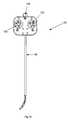
- FIG. 3is a perspective view of a catheter instrument used in either of the robotic surgical systems of FIGS. 1 and 2 ;
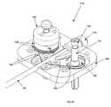
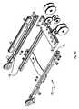
- FIG. 4is a perspective view of a coaxial guide/sheath catheter instrument used in either of the robotic surgical systems of FIGS. 1 and 2 ;
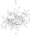
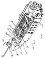
- FIG. 5is a perspective view of the coaxial guide/sheath catheter instrument of FIG. 4 and a portion of an instrument driver on which the catheter instrument is to be mounted;
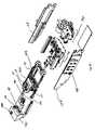
- FIG. 6is a partially disassembled perspective view of a proximal drivable assembly of the catheter instrument of FIG. 3 ;
- FIG. 7is another perspective view of the proximal drivable assembly of FIG. 6 ;
- FIG. 8is a perspective view of one control element interface assembly used in the proximal drivable assembly of FIG. 6 ;
- FIG. 9is a partially disassembled perspective view of the control element interface assembly of FIG. 8 ;
- FIG. 10is a top view of a pulley used in the control element interface assembly of FIG. 8 ;
- FIG. 11is a profile view of the pulley of FIG. 10 ;
- FIG. 12is a top perspective view of a top base portion used in the proximal drivable assembly of FIG. 6 ;
- FIG. 13is a bottom perspective view of the top base portion of FIG. 12 ;
- FIG. 14is a top perspective view of a bottom base portion used in the proximal drivable assembly of FIG. 6 ;
- FIG. 15is a bottom perspective view of the bottom base portion of FIG. 14 ;
- FIG. 16is a top view of another catheter instrument that can be used in either of the robotic surgical systems of FIGS. 1 and 2 ;
- FIG. 17is a partially dissembled top view of the catheter instrument of FIG. 16 ;
- FIG. 18is another partially disassembled top view of the catheter instrument of FIG. 16 ;
- FIG. 19is a partially disassembled perspective view of a proximal drivable assembly used in the catheter instrument of FIG. 16 ;
- FIG. 20is another partially disassembled perspective view of the proximal drivable assembly of FIG. 19 ;
- FIG. 21is a partially disassembled perspective view of another proximal drivable assembly that can be used in the catheter instrument of FIG. 16 ;
- FIG. 22is a partially disassembled top view of the proximal drivable assembly of FIG. 21 ;
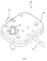
- FIG. 23is a perspective view of a proximal drivable assembly of the sheath instrument shown in FIG. 4 ;
- FIG. 24is a top perspective view of a bottom base portion of the proximal drivable assembly of FIG. 23 ;
- FIG. 25is a bottom view of a top base portion of the proximal drivable assembly of FIG. 23 ;
- FIG. 26is a bottom perspective view of the bottom base portion of FIG. 24 ;
- FIG. 27is a partially disassembled perspective view of another proximal drivable assembly that can be used in the sheath instrument shown in FIG. 4 ;
- FIG. 28is another partially assembled perspective view of the proximal drivable assembly of FIG. 27 ;
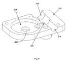
- FIG. 29is a partially disassembled perspective view of still another proximal drivable assembly that can be used in the sheath instrument shown in FIG. 4 ;
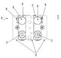
- FIG. 30is a partially disassembled perspective view of yet another proximal drivable assembly that can be used in the sheath instrument shown in FIG. 4 ;
- FIG. 31is a side schematic view of a instrument driver used in either of the robotic catheter systems of FIGS. 1 and 2 ;
- FIG. 32is a top schematic view of the instrument driver of FIG. 31 ;
- FIG. 33is partially disassembled perspective view of the instrument driver of FIG. 31 ;
- FIG. 34is another partially disassembled perspective view of the instrument driver of FIG. 31 ;
- FIG. 35is still another partially disassembled perspective view of the instrument driver of FIG. 31 ;
- FIG. 36is a side view of a motor and cabling assembly used in the instrument driver of FIG. 33 ;
- FIG. 37is a partially disassembled perspective view of the instrument driver of FIG. 33 and an instrument driver mount;
- FIG. 38is a partially cutaway perspective view of another instrument driver that can be used in the either of the robotic catheter systems of FIGS. 1 and 2 ;
- FIG. 39is top view of a carriage used in the instrument driver of FIG. 38 ;
- FIG. 40is an isometric perspective view of an alternate instrument driver, incorporating a winged split carriage design according to one embodiment, shown with a top cover removed and engaging respective guide and sheath instruments;
- FIG. 41is an isometric perspective view of a base member of the guide instrument shown in FIG. 40 ;
- FIG. 42is an isometric view of an underside of the guide instrument base of FIG. 41
- FIG. 43is an exploded perspective isometric view of a top plate of the guide instrument shown in FIG. 40 ;
- FIG. 44is a perspective isometric view of a low-profile control element interface assembly used in the guide instrument of FIG. 40 ;
- FIG. 45is an exploded view of the assembly of FIG. 44 ;
- FIG. 46is a partially exploded view of the instrument driver assembly of FIG. 40 ;
- FIG. 47is a further exploded view of a “wing” structures and associated members of the assembly of FIG. 46 ;
- FIG. 48is an exploded view illustrating relative constrained motion of a carriage base relative to an interface frame in the assembly of FIG. 40 ;
- FIGS. 49 and 50are exploded views of an alternate instrument driver assembly similar to that depicted in FIG. 40 , according to yet another embodiment.
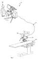
- a robotic surgical system32 includes an operator control station ( 2 ) located remotely from an operating table ( 22 ), an instrument driver ( 16 ) and instrument ( 18 ) coupled to the operating table ( 22 ) by a mounting brace ( 20 ), and a communication link ( 14 ), such as an external cable, that transfers signals between the operator control station ( 2 ) and instrument driver ( 16 ).
- the operator control station ( 2 )has a control button console ( 8 ), a master input device ( 12 ), and a display system ( 4 ).
- the master input device ( 12 )is a multi-degree-of-freedom device having multiple joints and associated encoders, thereby allowing an operator ( 24 ) to remotely control mechanical movements of the instrument ( 18 ).
- the instrument driver mounting brace ( 20 ) of the embodiment illustrated in FIG. 1is a relatively simple, arcuate-shaped structural member configured to position the instrument driver ( 16 ) above a patient (not shown) lying on the table ( 22 ).
- a movable setup mount ( 26 )can be used to movably support the instrument driver ( 16 ) above the table ( 22 ) to provide convenient access to the desired portions of the patient (not shown) and provide a means to lock the instrument driver ( 16 ) into position subsequent to preferred placement. Further details of various embodiments of operator control stations and movable setup mounts are disclosed in U.S. provisional patent application Ser. Nos. 60/677,580 and 60/678,097, which have previously been incorporated herein by reference.
- the instrument ( 18 )generally comprises a proximal drivable assembly ( 82 ), which includes an instrument base ( 48 ) and four control element interface assemblies ( 132 ), a catheter member ( 90 ), the proximal end of which is mounted within the instrument base ( 48 ), and four control or tension elements, such as cables (not shown), extending within the catheter member ( 90 ) and operably coupled to the four control element interface assemblies ( 132 ), such that operation of the interface assemblies ( 132 ) bends the distal end of the catheter member ( 90 ) in four separate directions, e.g., by displacing one of the control elements in the proximal direction to deflect the distal end of the catheter member ( 90 ) in the predetermined direction dictated by the one control element, while allowing the other three control elements to be displaced in the distal direction as a natural consequence of the catheter member deflect.
- the interface assemblies ( 132 )can be operated to displace two circumferentially adjacent control elements
- a set of two instruments ( 28 )comprises the afore-described instrument ( 18 ), which can be referred to as a guide instrument ( 18 ) in this configuration, and a coaxially coupled and independently controllable sheath instrument ( 30 ).
- the sheath instrument ( 30 )generally comprises a drivable assembly ( 84 ), which includes an instrument base ( 46 ) and a single control element interface assembly ( 132 ), a sheath catheter member ( 208 ), the proximal end of which is mounted within the instrument base ( 46 ), and a single control or tension element, such as a cable (not shown) extending within the sheath catheter member ( 208 ) and coupled to the interface assembly ( 132 ), such that operation of the interface assembly ( 132 ) bends the distal end of the sheath catheter member ( 208 ) in one direction.
- a drivable assembly ( 84 )which includes an instrument base ( 46 ) and a single control element interface assembly ( 132 ), a sheath catheter member ( 208 ), the proximal end of which is mounted within the instrument base ( 46 ), and a single control or tension element, such as a cable (not shown) extending within the sheath catheter member ( 208 ) and coupled to the
- the sheath instrument ( 30 )need not be as driveable or controllable as the associated guide instrument ( 18 ), because the sheath instrument ( 30 ) is generally used to contribute to the remote tissue access schema by providing a conduit for the guide instrument ( 18 ), and to generally point the guide catheter member ( 90 ) in the correct direction.
- Such movementis controlled by rolling the sheath catheter member ( 208 ) relative to the patient and bending the sheath catheter member ( 208 ) in one or more directions with the control element.
- the set of instruments ( 28 )is depicted adjacent an instrument driver ( 16 ) to illustrate an exemplary mounting scheme.
- the sheath instrument ( 30 )may be coupled to the depicted instrument driver ( 16 ) at a sheath instrument interface surface ( 38 ) by aligning and sliding holes (not shown) of the sheath instrument base ( 46 ) over pins ( 42 ) extending upward from the interface surface ( 38 ).
- the drivable assembly ( 84 ) of the sheath instrument ( 30 )conveniently mates with an interface socket ( 44 ) of the driver ( 16 ) once the sheath instrument base ( 46 ) is mounted to the instrument driver ( 16 ).
- the guide instrument ( 18 )may be coupled to the instrument driver ( 16 ) at a guide instrument interface surface ( 40 ) by aligning and sliding holes (not shown) of the guide instrument base ( 48 ) over mounting pins ( 42 ) extending upward from the interface surface ( 40 ).
- the drivable assemblies ( 82 ) of the guide instrument ( 18 )conveniently mate with corresponding interface sockets ( 44 ) of the driver ( 16 ) once the guide instrument ( 18 ) is mounted to the instrument driver ( 16 ).
- the interface surface ( 40 )takes the form of a movable carriage on which the guide instrument base ( 48 ) will ride.
- the instruments ( 18 , 30 )are provided for a medical procedure in sterile packaging, while the instrument driver ( 16 ) is not necessarily sterile.
- the nonsterile instrument driver ( 16 )must be isolated from the patient by a sterile barrier of some type. Further details on the mounting of the instruments ( 28 ) to the instrument driver ( 16 ) and the use of sterile drapes are disclosed in U.S. provisional patent application Ser. Nos. 60/677,580 and 60/678,097, which have previously been incorporated herein by reference.
- the driving mechanisms of the instrument driver ( 16 )mate directly with the drivable assemblies of the respective instruments ( 18 ), ( 30 ), thereby obviating the need to utilize intervening coupling devices that may otherwise adversely affect the desired accuracy in the predicted movement of the catheter deflections, e.g., due to unpredictable flexing and bending in the intervening coupling devices. It can also be appreciated that the above-described mounting scheme allows a user to rapidly exchange the instruments ( 18 ), ( 30 ), which are typically used only one time and thus disposable.
- FIGS. 6-15depict certain aspects of the drivable assembly ( 82 ) of the guide instrument ( 18 ).
- the guide instrument base ( 48 ) of the drivable assembly ( 82 )generally comprises a top portion ( 152 ) and bottom portion ( 156 ), which are interfaced together to house the four control element interface assemblies ( 132 ), catheter member ( 90 ), a seal ( 170 ), and a purging port ( 172 ).
- the seal ( 170 )preferably comprises a silicon rubber seal configured to accommodate insertion of working members or instruments, such as, e.g., relatively small profile guidewires (e.g., in the range of 0.035′′ diameter), or relatively larger profile catheters (e.g., of up to 7 French or even larger).
- the purging port ( 172 )may be utilized to purge the guide catheter member ( 90 ), or circulate fluids therein
- each control element interface assembly ( 132 )comprises an axel ( 54 ), a control element pulley ( 136 ), a manual adjustment knob ( 86 ), and a drive engagement knob ( 134 ).
- the pulley ( 136 )is configured to be rotated one way to spool, and thus proximal displace, a respective control element, thereby deflecting the distal end of the catheter member ( 90 ) in the predetermined direction dictated by the proximally displaced control element, and to be rotated the opposite way to unspool, and thus distally displace, the control element, thereby allowing the distal end of the catheter member ( 90 ) to deflect in another direction dictated by another control element interface assembly ( 132 ).
- the manual adjustment knob ( 86 )is configured to facilitate manual adjustment of control element tensions during setup of the instrument ( 18 ) upon the instrument driver ( 16 ). It is held in place against the axel ( 54 ) with a clamp screw ( 138 ), and houses a range of motion limitation pin ( 140 ), which limits the range of motion of the axel ( 54 ) subsequent to setup and tightening of the clamp screw ( 138 ).
- the drive engagement knob ( 134 )may take a shape similar to a screw with a long threaded portion configured to extend through the axel ( 54 ) to engage a tapered nut ( 142 ), as shown.
- Twisting of the drive engagement knob ( 134 )causes the tapered nut ( 142 ) to urge the teeth ( 144 ) of the axel outward, thereby engaging whatever structures surround the lower portion of the axel ( 54 ), including but not limited to an instrument driver interface socket ( 44 ).
- the control element pulley ( 136 )comprises a central hole ( 148 ) sized for a press fit upon the axel ( 54 ), and a control element termination engagement slot ( 146 ) configured to capture a control element terminator, such as a lead or steel cable terminator, that is pushed into the slot before a control element is wound around the pulley ( 136 ) during manufacture or rebuilding.
- the pulley ( 136 )preferably has a flanged shape ( 150 ) to facilitate winding and positional maintenance of a control element.
- the rotation of the pulleys ( 136 )are limited to a predetermined range.
- the previously described motion limitation pins ( 140 )interface with slots ( 154 ) formed in the top portion ( 152 ) of the guide instrument base ( 48 ) (best shown in FIG. 12 ).
- the top portion ( 152 )also comprises two pulley recesses ( 160 ) for accommodating two of the four pulleys (not shown), and associated control element splay tracks ( 158 ) for guiding control elements (not shown) from apertures in the guide catheter member ( 90 ) into the two pulleys.
- the bottom portion ( 156 )includes two additional pulley recesses ( 160 ) for accommodating the remaining two of the four pulleys (not shown), and associated control element splay tracks ( 158 ) for guiding control elements (not shown) from apertures in the guide catheter member ( 90 ) into the remaining two pulleys.
- Each of the top portion ( 152 ) and bottom portion ( 156 )also comprises four axel interface holes ( 660 ) for accommodating the axels ( 54 ) of the corresponding control element interface assemblies ( 132 ).
- the top portion ( 152 ) and bottom portion ( 156 )also have spatially corresponding catheter recesses ( 162 ) and seal recesses ( 164 ) for accommodating the proximal end of the guide catheter member ( 90 ).
- the top ( 152 ) and bottom ( 156 ) portions of the guide instrument base ( 48 )can be “sandwiched” together to capture the proximal end of the guide catheter member ( 90 ) within these recesses.
- the bottom surface of the bottom portion ( 156 )comprises magnets ( 166 ) to facilitate mounting of the guide instrument ( 18 ) on the instrument driver ( 16 ).
- the bottom portion ( 156 )also has mounting pin interface holes ( 168 ) formed through it to accommodate mounting pins ( 42 ) (shown in FIG. 5 ) from the instrument driver ( 16 ). Further, the bottom portion ( 156 ) preferably has a generally asymmetric geometry to ensure that it will only fit the underlying instrument driver ( 16 ) snugly in one way.
- drivable assembly ( 82 ) of the guide instrument ( 18 )comprises four control element interface assemblies ( 132 ) that control four corresponding control elements
- drivable assembliesmay include any number of control element interface assemblies ( 132 ) for controlling the same number of control elements depending on the application.
- a drivable assembly ( 82 )may include one, two, three, or more than four control element interface assemblies ( 132 ), depending on the desired number of control elements to be tensioned.
- FIGS. 16-22other embodiments of guide instruments are depicted having the respective capabilities to drive four control elements with only two control element interface assemblies.
- many of the same componentsare utilized in these embodiments.
- such component matchingis by no means required to accomplish the described functions, and many alternative arrangements are possible within the scope of the inventions disclosed herein.
- a guide instrument ( 174 )has only two control element interface assemblies ( 132 ) configured to drive four control elements ( 192 ) (shown in FIG. 18 ).
- each control element interface assembly ( 132 )comprises a stacked pair of pulleys ( 136 ) to accommodate a respective pair of control elements ( 192 ), as illustrated in FIGS. 19 and 20 .
- Rotation of the pair of pulleys ( 136 ) in the opposite directionunspools, thus distally displacing, the previously proximal displaced control element ( 192 ), while spooling, and thus proximal displacing, the previously distally displaced control element ( 192 ), thereby deflecting the distal end of the catheter member ( 90 ) in the predetermined direction dictated by the newly tensioned control element ( 192 ).
- the control element interface assemblies ( 132 )are also configured to maintain a minimal amount of tension using fixed idler control element pathways ( 196 ) to align the control elements ( 192 ) with the sets of two pulleys ( 136 ) included within the respective control element interface assemblies ( 132 ).
- tensionmay be maintained in the control elements ( 192 ), with pre-tensioning, or pre-stressing, to prevent control element slack.
- Tensionis also maintained on the four control elements ( 192 ) using a slotted guide instrument base ( 188 ).
- the guide instrument base ( 188 )forms slots ( 190 ) through which an instrument driver tensioning mechanism, which will be described in further detail below, may keep control elements ( 192 ) taut during operation of the instrument ( 174 ) by translating the respective control element interface assemblies ( 132 ) within the slots ( 190 ).
- an instrument driver tensioning mechanismwhich will be described in further detail below
- an instrument driver tensioning mechanismwhich will be described in further detail below
- the slots ( 190 )are rectilinear.
- the slots ( 190 )can have any shape, such as arcuate, that allows the respective control element interface assembly ( 132 ) to translate relative to the instrument base ( 188 ).
- slots ( 190 ) in which the respective control element interface assemblies ( 132 ) can translatealso provides an addition means for deflecting the distal end of the catheter member ( 90 ).
- a control element interface assembly ( 132 )can be proximally displaced in a respective slot ( 190 ), which without rotation of the control element interface assembly ( 132 ), tensions both control elements ( 192 ).
- control element interface assembly ( 132 )is proximally translated within the slot ( 190 ), it is rotated in one direction to unspool one of the control elements ( 192 ) to facilitate its axial displacement in the distal direction as the other control element ( 192 ) is axially displaced in the proximal direction by the proximal translation of the control element interface assembly ( 132 ) and spooling of the control element ( 192 ) onto the control element interface assembly ( 132 ).
- the distal end of the catheter memberwill be deflected in the predetermined direction dictated by the other control element ( 192 ).
- a guide instrument ( 176 )is similar to that illustrated in FIG. 19 , with the exception that it comprises four spring-loaded idlers ( 198 ) to assist with tensioning each of the four control elements ( 192 ).
- Each of the control elements ( 192 )passes through a spring loaded idler ( 198 ), which urges the control element ( 192 ) into tension by trying to rotate ( 200 ).
- FIGS. 23-26depict certain aspects of the drivable assembly ( 132 ) of the sheath instrument ( 30 ).
- the sheath instrument base ( 46 ) of the drivable assembly ( 84 )generally comprises a top portion ( 212 ) and bottom portion ( 210 ), which are interfaced together to house the single control element interface assembly ( 132 ), sheath catheter member ( 208 ), a seal ( 204 ), and a purging port ( 206 ).
- the control element interface assembly ( 132 ) of the sheath instrument ( 30 )comprises an axel ( 54 ), a control element pulley (not shown), a manual adjustment knob ( 86 ), and a drive engagement knob ( 134 ) that function in the same manner to control the corresponding control element extending through the sheath catheter member ( 208 ).
- the seal ( 204 )is generally larger than the seal on the guide instrument ( 18 ) due to the larger diameters of elongate members that may be inserted into the sheath instrument ( 30 ) as part of a medical procedure.
- the purging port ( 206 )may be utilized to purge the sheath catheter member ( 208 ), or circulate fluids therein.
- the bottom portion ( 210 )comprises a pulley recess ( 218 ) for accommodating the single pulley (not shown), and an associated control element splay track ( 220 ) for guiding the control element (not shown) from an aperture in the sheath catheter member ( 208 ) into the pulley.
- each of the bottom portion ( 210 ) and top portion ( 212 )also comprises an axel interface hole ( 222 ) for accommodating the axel ( 54 ) of the control element interface assembly 132 .
- the bottom portion ( 210 ) and top portion ( 212 )also have spatially corresponding catheter recesses ( 216 ) and seal recesses ( 214 ) for accommodating the proximal end of the sheath catheter member ( 208 ).
- the bottom ( 210 ) and top ( 212 ) portions of the sheath instrument base ( 46 )can be “sandwiched” together to capture the proximal end of the sheath catheter member ( 208 ) within such recesses.
- the bottom surface of the bottom portion ( 210 )comprises magnets ( 166 ) to facilitate mounting of the sheath instrument ( 30 ) on the instrument driver ( 16 ).
- the bottom portion ( 210 )also has mounting pin interface holes ( 168 ) formed through it to accommodate mounting pins ( 42 ) (shown in FIG. 5 ) from the instrument driver ( 16 ).
- the bottom portion ( 156 )preferably has a generally asymmetric geometry to ensure that it will only fit the underlying instrument driver ( 16 ) snugly in one way.
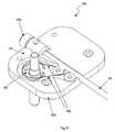
- FIGS. 27-30other embodiments of sheath instruments are depicted having the respective capabilities to drive two control elements with only one control element interface assembly.
- many of the same componentsare utilized in these embodiments.
- such component matchingis by no means required to accomplish the described functions, and many alternative arrangements are possible within the scope of the inventions disclosed herein.
- a sheath instrument ( 186 )has only one control element interface assembly ( 132 ) (shown with manual adjustment knob and control pulley removed) configured to drive two control elements ( 192 ) (shown in FIG. 27 ).
- each control element interface assembly ( 132 )comprises a stacked pair of pulleys (not shown) to accommodate a respective pair of control elements ( 192 ).
- the previously described guide instrument illustrated in FIG. 19comprises a stacked pair of pulleys (not shown) to accommodate a respective pair of control elements ( 192 ).
- the control element interface assembly ( 132 )is also configured to maintain a minimal amount of tension on the two control elements ( 192 ) using a slotted guide instrument base ( 202 ).
- the sheath instrument base ( 202 )forms slots ( 190 ) through which an instrument driver tensioning mechanism may keep control elements ( 192 ) taut during operation of the instrument ( 186 ) by translating the control element interface assembly ( 132 ) within the slot ( 190 ).
- yet another sheath instrument ( 182 )has a single control element interface assembly ( 132 ) (shown with manual adjustment knob removed) and two control elements ( 192 ).
- the sheath instrument ( 182 )is not configured for slotted tensioning. Instead, the control elements ( 192 ) of this embodiment may be pre-tensioned and kept in position with the help of a fixed idler control element pathway ( 196 ) to facilitate maintenance of tension for control purposes.
- still another sheath instrument ( 184 )has a single control element interface assembly ( 132 ) (shown with manual adjustment knob removed) and two control elements ( 192 ), with a spring-loaded idler ( 198 ) tensioning of the control elements ( 192 ).
- the spring-loaded idlersurge ( 200 ) the control elements ( 192 ) into tension to facilitate control.
- FIGS. 31-39depict various aspects of embodiments of an instrument driver ( 16 ).
- the instrument driver ( 16 )comprises a carriage ( 240 ) that is slidably mounted upon a platform ( 246 ), which is slidably mounted to a base structure ( 248 ).
- the slidable mounting ( 250 ) at these interfacesmay be accomplished with high-precision linear bearings.
- the depicted systemhas two cables ( 256 , 258 ) running through a plurality of pulleys ( 244 ) to accomplish motorized, synchronized relative motion of the carriage ( 240 ) and platform ( 246 ) along the slidable interfaces ( 250 ).
- the carriage ( 240 )feels a force of 2*T. Further, as the motor ( 242 ) pulls the carriage displacement cable ( 256 ) by a displacement X, the carriage moves by X/2, and the platform ( 246 ) moves by half that amount, or X/4, due to its “pulleyed” synchronization cable ( 258 ) and termination ( 252 ).
- the instrument driver ( 16 )is depicted as interfaced with the guide instrument ( 18 ) and sheath instrument ( 30 ).
- the sheath instrument interface surface ( 38 )remains stationary, and requires only a simple motor actuation in order for the sheath catheter member ( 208 ) to be deflected using an interfaced control element via a control element interface assembly ( 132 ).
- sheath socket drive pulley272
- sheath instrument interface socket168
- an axel ( 54 ) of a respective control element interface assembly ( 132 ) of the sheath instrument ( 30 )is mated
- a capstan pulleynot shown
- the drive motor for the sheath socket drive schemais hidden under the linear bearing interface assembly.
- the drive schema for the four guide instrument interface sockets ( 270 )is more complicated, due in part to the fact that they are coupled to a carriage ( 240 ) configured to move linearly along a linear bearing interface ( 250 ) to provide for axial movement of the guide instrument ( 90 ) toward the patient relative to the instrument driver ( 16 ), operating table ( 22 ), and sheath instrument ( 30 ).
- the cabling and motor schema that moves the carriage ( 240 ) along the linear bearing interface ( 250 )is an implementation of the diagrammatic view depicted in FIG. 31 .
- the cabling and motor schema that drives each of the four depicted guide instrument interface sockets ( 270 )is an implementation of the diagrammatic view depicted in FIG. 32 .
- a group of four motors ( 290 )is used to respectively drive the four guide instrument interface sockets ( 270 ).
- Each motor ( 290 )has an associated high-precision encoder for controls purposes.
- the instrument interface cable ( 264 )bends around a pulley ( 244 ) and completes part of its loop to an instrument interface pulley ( 260 ) rotatably coupled to the carriage ( 240 ) and coupled to a guide instrument interface socket ( 270 ), around the instrument interface pulley ( 260 ), and back to a motor capstan pulley ( 294 ).
- two ends of a cut cable looppreferably are terminated at each capstan ( 294 ).
- a group of two motorsone hidden, one visible ( 288 )
- encoders292
- the instrument driver ( 16 )is rotatably mounted to an instrument driver base ( 274 ), which is configured to interface with an instrument driver mounting brace (not shown), such as that depicted in FIG. 1 , or a movable setup joint construct (not shown), such as that depicted in FIG. 2 .
- Rotation between the instrument driver base ( 274 ) and an instrument driver base plate ( 276 ) to which it is coupledis facilitated by a heavy-duty flanged bearing structure ( 278 ).
- the flanged bearing structure ( 278 )is configured to allow rotation of the body of the instrument driver ( 16 ) about an axis approximately coincident with the longitudinal axis of a guide instrument (not shown) when the guide instrument is mounted upon the instrument driver ( 16 ) in a neutral position.
- This rotationpreferably is automated or powered by a roll motor ( 280 ) and a simple roll cable loop ( 286 ), which extends around portions of the instrument driver base plate and terminates as depicted ( 282 , 284 ).
- roll rotationmay be manually actuated and locked into place with a conventional clamping mechanism.
- the carriage ( 240 ) depicted in the embodiments of FIGS. 31-37generally comprises a structural box configured to house the instrument interface sockets and associated instrument interface pulleys.
- a split carriage ( 296 )is depicted, comprising a main carriage body ( 304 ) similar to that of the non split carriage depicted in the previous carriage ( 240 ), and either one or two linearly movable portions ( 302 ), which are configured to slide relative to the main carriage body ( 304 ) when driven along either forward or backward relative to the main carriage body ( 304 ) by a gear ( 300 ) placed into one of the guide instrument interface sockets, the gear ( 300 ) configured to interface with a rack ( 298 ) mounted upon the main carriage body ( 304 ) adjacent the gear ( 300 ).
- Each movable portion ( 302 )comprises a guide instrument interface socket ( 270 ) in which an axel ( 54 ) of a respective control element interface assembly ( 132 ) of the guide instrument ( 18 ) is mated.
- the guide instrument ( 18 )has the slotted guide instrument base ( 188 ) illustrated in FIG. 18
- movement of the movable portion ( 302 ) along a rectilinear path relative to the main carriage body ( 304 ) on which the instrument basewill move the control element interface assembly ( 132 ) along the same rectilinear path (i.e., within the rectilinear slots ( 190 )) relative to the instrument base ( 188 ).
- the carriage ( 296 )need not be split on both sides, but may have one split side and one non-split side. Further, while a carriage with four guide instrument interface sockets is suitable for driving a guide instrument with anywhere from one to four control element interface assemblies, the additional hardware required for all four control element interface assemblies may be undesirable if an instrument only requires only one or two.
- FIGS. 40-50another variation of an instrument driver is depicted, comprising a variation of a split carriage design. Unlike embodiments in which each instrument base interface is moved straight along a slot, rotated, or both (independently), the embodiment of FIGS. 40-50 provides rotation and/or arcuate slot motion by a “winged” split carriage design, wherein the tension member pulleys and axles may be rotated about the axle axis, or moved along an arcuate pathway, independently.
- a winged split carriage instrument driver ( 135 )is depicted coupled to a guide instrument ( 215 ) configured for the winged split carriage with a specialized guide instrument base ( 141 ) having two arcuate slots ( 145 ) as opposed to the straight slots of other embodiments.
- One or more electronics boards ( 139 )preferably are coupled to the main housing structure ( 137 ) of the winged split carriage instrument driver ( 135 ).
- the depicted assemblyalso comprises a sheath instrument ( 30 ) movably threaded over at least a portion of the guide instrument ( 215 ) and coupled to the sheath frame block ( 185 ) which is coupled to the main housing structure ( 137 ) when the depicted assembly is fully assembled.
- a winged instrument driver guide instrument base ( 141 )is depicted showing the arcuate slots ( 145 ) in greater detail, as well as a winged instrument driver guide instrument base top plate ( 143 ), which is configured to be fitted down upon the proximal tubular portion of a guide instrument catheter member (not shown) to maintain the relative positioning of the catheter member (not shown) relative to the winged instrument driver guide instrument base ( 141 ).
- An underside isometric view of the guide instrument base ( 141 )is depicted in FIG. 42 .
- a low-profile control element interface assembly( 147 ) is configured to rotate about the longitudinal axis of the interface assembly ( 219 ) while also slidably translating through the associated arcuate slot ( 145 ).
- FIG. 43depicts an exploded view of the winged instrument driver guide instrument base top plate ( 143 ) and winged instrument driver guide instrument base ( 141 ) depicted in FIG. 41 , also showing the arcuate slots ( 145 ) defined therein.
- a low-profile control element interface assembly( 147 ) is shown in isometric view comprising a splined axle ( 157 ) coupled to a pulley flange ( 153 ), and also coupled to a set of control element pulleys ( 155 ) which are compressed between a low-profile manual adjustment knob ( 151 ) and the pulley flange ( 153 ) with a retaining fastener ( 149 ), such as a screw.
- An exploded view of the same structuresis depicted in FIG. 45 . Also shown in FIG.
- low-profile control element interface assembly ( 147 )is a pin ( 159 ) configured to prevent relative rotational displacement between the two control element pulleys ( 155 ) when the low-profile control element interface assembly ( 147 ) is assembled.
- the depicted embodiment of low-profile control element interface assembly ( 147 )may be utilized with any of the aforementioned instrument base and instrument driver assemblies, subject to the requirement that the instrument interface sockets, labeled 44 , for example in FIG. 5 , preferably are also geometrically matched for a splined interface between socket and axle facilitating highly-efficient transfer of loads between the matched socket and axle.
- the low-profile control element interface assembly ( 147 )preferably comprises polymers or metals which may be formed or machined into very high precision subassemblies or parts which are low in weight, high in hardness, and low in fracture toughness.
- each of the components of the low-profile control element interface assembly ( 147 )comprises polycarbonate or ultra-high-molecular-weight polyethylene.
- a winged split carriage assemblyis depicted in semi-exploded view.
- the winged carriage base ( 173 )is configured to rotatably support two independently rotatable wing structures ( 221 ), each comprising a bottom portion ( 165 ) and a top portion ( 163 ).
- a further exploded view of the wing structures ( 221 ) and associated membersare depicted in FIG. 47 .
- Rotatably coupled to the rotatable wing structures ( 221 )is a set of control element pulleys ( 167 ) to which a splined instrument interface socket ( 161 ) is coupled.
- the winged carriage base ( 173 )is configured to slidably couple to a carriage interface frame (not shown) with bearings ( 179 ). As shown in FIG. 48 , slots ( 181 ) constrain the motion of the winged carriage base ( 173 ) relative to the carriage interface frame ( 191 ) to linear motion.
- Shafts and bearingsare utilized to rotatably couple the wing structures ( 221 ) to the winged carriage base and facilitate rotational motion of the wing structures ( 221 ) about the axis of the pertinent coupling shaft ( 171 ). Similar shaft and bearing configurations are utilized to provide for rotation of the control element pulleys ( 167 ) relative to the wing structures ( 221 ).
- the winged split carriage designis configured to allow for independent motion of each of two wing structures ( 221 ), while also allowing for independent rotational motion of two sets of control element pulleys ( 167 ) and thereby instrument interface sockets ( 161 ).
- each of the control element interface assemblies ( 147 )may be rotated about their longitudinal axis, and also arcuately translated through the arcuate slot formed in the instrument base ( 141 ).
- This arrangementprovides for tensioning and control of two control elements, one around each of the control element pulleys ( 167 ) on each of the control element interface assemblies ( 147 ), with actuation of a single control element interface assembly ( 147 ).
- four control elementsmay be driven with the actuation of only two control element interface assemblies ( 147 ).
- FIG. 49an exploded view of an assembly similar to that depicted in FIG. 40 is depicted. Neither the sheath instrument, the two control element interface assemblies, nor the guide instrument catheter member are depicted in FIG. 49 .
- the instrument driver roll assembly ( 195 ) and instrument driver motor/gear assembly ( 193 )are coupled to the main frame ( 137 ) of the instrument driver.
- redundant encoder readers ( 211 ) associated with each of four control element drive motors ( 209 ) of this embodimentfacilitate high precision rotational position readings of the motor shafts and prevent position read errors.
- the motor output shaftsare coupled to bevel gears ( 207 ) which are interfaced with another set of bevel gears ( 213 ) and thereby configured to drive the depicted vertical output shafts ( 205 ).
- the motor/gear interface block ( 203 )is utilized to couple the motors, gears, and shafts into positions relative to each other and the main frame of the instrument driver (not shown), while constraining motions generally to rotational motions of shafts, motors, gears, and bearings.
- the rotation and arcuate translation of the winged structure instrument interface sockets ( 161 ) relative to the winged carriage base ( 173 ) and wing structures ( 221 )is a key difference between the winged split carriage instrument driver and the non-winged embodiments described herein.
Landscapes
- Health & Medical Sciences (AREA)
- Life Sciences & Earth Sciences (AREA)
- Engineering & Computer Science (AREA)
- Surgery (AREA)
- Public Health (AREA)
- Molecular Biology (AREA)
- Veterinary Medicine (AREA)
- Nuclear Medicine, Radiotherapy & Molecular Imaging (AREA)
- Biomedical Technology (AREA)
- Heart & Thoracic Surgery (AREA)
- Medical Informatics (AREA)
- General Health & Medical Sciences (AREA)
- Animal Behavior & Ethology (AREA)
- Robotics (AREA)
- Pathology (AREA)
- Biophysics (AREA)
- Physics & Mathematics (AREA)
- Radiology & Medical Imaging (AREA)
- Oral & Maxillofacial Surgery (AREA)
- Media Introduction/Drainage Providing Device (AREA)
Abstract
Description
Claims (19)
Priority Applications (1)
| Application Number | Priority Date | Filing Date | Title |
|---|---|---|---|
| US11/176,954US8021326B2 (en) | 2004-03-05 | 2005-07-06 | Instrument driver for robotic catheter system |
Applications Claiming Priority (8)
| Application Number | Priority Date | Filing Date | Title |
|---|---|---|---|
| US55096104P | 2004-03-05 | 2004-03-05 | |
| US55302904P | 2004-03-12 | 2004-03-12 | |
| US60086904P | 2004-08-12 | 2004-08-12 | |
| US64450505P | 2005-01-13 | 2005-01-13 | |
| US11/073,363US7972298B2 (en) | 2004-03-05 | 2005-03-04 | Robotic catheter system |
| US67758005P | 2005-05-03 | 2005-05-03 | |
| US67809705P | 2005-05-04 | 2005-05-04 | |
| US11/176,954US8021326B2 (en) | 2004-03-05 | 2005-07-06 | Instrument driver for robotic catheter system |
Related Parent Applications (1)
| Application Number | Title | Priority Date | Filing Date |
|---|---|---|---|
| US11/073,363Continuation-In-PartUS7972298B2 (en) | 2004-03-05 | 2005-03-04 | Robotic catheter system |
Publications (2)
| Publication Number | Publication Date |
|---|---|
| US20060084945A1 US20060084945A1 (en) | 2006-04-20 |
| US8021326B2true US8021326B2 (en) | 2011-09-20 |
Family
ID=46322231
Family Applications (1)
| Application Number | Title | Priority Date | Filing Date |
|---|---|---|---|
| US11/176,954Active2030-04-26US8021326B2 (en) | 2004-03-05 | 2005-07-06 | Instrument driver for robotic catheter system |
Country Status (1)
| Country | Link |
|---|---|
| US (1) | US8021326B2 (en) |
Cited By (63)
| Publication number | Priority date | Publication date | Assignee | Title |
|---|---|---|---|---|
| US20110015484A1 (en)* | 2009-07-16 | 2011-01-20 | Alvarez Jeffrey B | Endoscopic robotic catheter system |
| US20110319910A1 (en)* | 2007-08-14 | 2011-12-29 | Hansen Medical, Inc. | Methods and devices for controlling a shapeable instrument |
| US8652031B2 (en) | 2011-12-29 | 2014-02-18 | St. Jude Medical, Atrial Fibrillation Division, Inc. | Remote guidance system for medical devices for use in environments having electromagnetic interference |
| US9220569B2 (en) | 2013-03-13 | 2015-12-29 | Ethicon Endo-Surgery, Inc. | Electrosurgical device with disposable shaft having translating gear and snap fit |
| US9566201B2 (en) | 2007-02-02 | 2017-02-14 | Hansen Medical, Inc. | Mounting support assembly for suspending a medical instrument driver above an operating table |
| US10143360B2 (en) | 2010-06-24 | 2018-12-04 | Auris Health, Inc. | Methods and devices for controlling a shapeable medical device |
| US10159533B2 (en) | 2014-07-01 | 2018-12-25 | Auris Health, Inc. | Surgical system with configurable rail-mounted mechanical arms |
| US10213264B2 (en) | 2013-03-14 | 2019-02-26 | Auris Health, Inc. | Catheter tension sensing |
| US10350390B2 (en) | 2011-01-20 | 2019-07-16 | Auris Health, Inc. | System and method for endoluminal and translumenal therapy |
| US10357324B2 (en) | 2015-02-20 | 2019-07-23 | Stryker Corporation | Sterile barrier assembly, mounting system, and method for coupling surgical components |
| US10363104B2 (en) | 2014-01-31 | 2019-07-30 | Covidien Lp | Interfaces for surgical systems |
| US10368951B2 (en) | 2005-03-04 | 2019-08-06 | Auris Health, Inc. | Robotic catheter system and methods |
| US10500001B2 (en) | 2015-05-15 | 2019-12-10 | Auris Health, Inc. | Surgical robotics system |
| US20200060516A1 (en)* | 2018-08-24 | 2020-02-27 | Auris Health, Inc. | Manually and robotically controllable medical instruments |
| US10667871B2 (en) | 2014-09-30 | 2020-06-02 | Auris Health, Inc. | Configurable robotic surgical system with virtual rail and flexible endoscope |
| US10702348B2 (en) | 2015-04-09 | 2020-07-07 | Auris Health, Inc. | Surgical system with configurable rail-mounted mechanical arms |
| US10736219B2 (en) | 2016-05-26 | 2020-08-04 | Covidien Lp | Instrument drive units |
| US10751140B2 (en) | 2018-06-07 | 2020-08-25 | Auris Health, Inc. | Robotic medical systems with high force instruments |
| US10849702B2 (en) | 2013-03-15 | 2020-12-01 | Auris Health, Inc. | User input devices for controlling manipulation of guidewires and catheters |
| US10874468B2 (en) | 2004-03-05 | 2020-12-29 | Auris Health, Inc. | Robotic catheter system |
| US10959792B1 (en) | 2019-09-26 | 2021-03-30 | Auris Health, Inc. | Systems and methods for collision detection and avoidance |
| US11007641B2 (en) | 2017-07-17 | 2021-05-18 | Canon U.S.A., Inc. | Continuum robot control methods and apparatus |
| US11020016B2 (en) | 2013-05-30 | 2021-06-01 | Auris Health, Inc. | System and method for displaying anatomy and devices on a movable display |
| US11045265B2 (en) | 2016-05-26 | 2021-06-29 | Covidien Lp | Robotic surgical assemblies and instrument drive units thereof |
| US11096754B2 (en) | 2017-10-04 | 2021-08-24 | Mako Surgical Corp. | Sterile drape assembly for surgical robot |
| US11197728B2 (en) | 2018-09-17 | 2021-12-14 | Auris Health, Inc. | Systems and methods for concomitant medical procedures |
| US11213363B2 (en) | 2013-03-14 | 2022-01-04 | Auris Health, Inc. | Catheter tension sensing |
| US11234780B2 (en) | 2019-09-10 | 2022-02-01 | Auris Health, Inc. | Systems and methods for kinematic optimization with shared robotic degrees-of-freedom |
| US11254009B2 (en) | 2018-12-20 | 2022-02-22 | Auris Health, Inc. | Systems and methods for robotic arm alignment and docking |
| US11272992B2 (en) | 2016-06-03 | 2022-03-15 | Covidien Lp | Robotic surgical assemblies and instrument drive units thereof |
| US11278366B2 (en) | 2017-04-27 | 2022-03-22 | Canon U.S.A., Inc. | Method for controlling a flexible manipulator |
| US11298195B2 (en) | 2019-12-31 | 2022-04-12 | Auris Health, Inc. | Anatomical feature identification and targeting |
| US11357586B2 (en) | 2020-06-30 | 2022-06-14 | Auris Health, Inc. | Systems and methods for saturated robotic movement |
| US11369448B2 (en) | 2019-04-08 | 2022-06-28 | Auris Health, Inc. | Systems, methods, and workflows for concomitant procedures |
| US11504020B2 (en) | 2019-10-15 | 2022-11-22 | Imperative Care, Inc. | Systems and methods for multivariate stroke detection |
| US11602372B2 (en) | 2019-12-31 | 2023-03-14 | Auris Health, Inc. | Alignment interfaces for percutaneous access |
| US11660147B2 (en) | 2019-12-31 | 2023-05-30 | Auris Health, Inc. | Alignment techniques for percutaneous access |
| US11744670B2 (en) | 2018-01-17 | 2023-09-05 | Auris Health, Inc. | Surgical platform with adjustable arm supports |
| US11839969B2 (en) | 2020-06-29 | 2023-12-12 | Auris Health, Inc. | Systems and methods for detecting contact between a link and an external object |
| US11857277B2 (en) | 2019-02-08 | 2024-01-02 | Auris Health, Inc. | Robotically controlled clot manipulation and removal |
| US11931901B2 (en) | 2020-06-30 | 2024-03-19 | Auris Health, Inc. | Robotic medical system with collision proximity indicators |
| US11969157B2 (en) | 2013-03-15 | 2024-04-30 | Auris Health, Inc. | Systems and methods for tracking robotically controlled medical instruments |
| US12023119B2 (en) | 2019-06-26 | 2024-07-02 | Auris Health, Inc. | Systems and methods for robotic arm alignment and docking |
| US12076100B2 (en) | 2018-09-28 | 2024-09-03 | Auris Health, Inc. | Robotic systems and methods for concomitant endoscopic and percutaneous medical procedures |
| US12082895B2 (en) | 2018-12-04 | 2024-09-10 | Mako Surgical Corp. | Robotic surgical system with a mounting assembly for attaching an end effector to a robotic arm |
| US12232838B2 (en) | 2021-08-12 | 2025-02-25 | Imperative Care, Inc. | Method of robotically performing a neurovascular procedure |
| US12245882B2 (en) | 2020-01-07 | 2025-03-11 | Cleerly, Inc. | Systems, methods, and devices for medical image analysis, diagnosis, risk stratification, decision making and/or disease tracking |
| USD1069809S1 (en) | 2022-08-25 | 2025-04-08 | Kandu Health, Inc. | Display screen or portion thereof with graphical user interface |
| US12283046B2 (en) | 2020-01-07 | 2025-04-22 | Cleerly, Inc. | Systems, methods, and devices for medical image analysis, diagnosis, risk stratification, decision making and/or disease tracking |
| US12299885B2 (en) | 2022-03-10 | 2025-05-13 | Cleerly, Inc. | Systems, devices, and methods for non-invasive image-based plaque analysis and risk determination |
| US12318161B2 (en) | 2021-10-05 | 2025-06-03 | Siemens Healthineers Endovascular Robotics, Inc. | Robotic actuation of elongated medical devices |
| US12324696B2 (en) | 2022-03-10 | 2025-06-10 | Cleerly, Inc. | Systems, devices, and methods for non-invasive image-based plaque analysis and risk determination |
| US12324695B2 (en) | 2020-01-07 | 2025-06-10 | Cleerly, Inc. | Systems, methods, and devices for medical image analysis, diagnosis, risk stratification, decision making and/or disease tracking |
| US12324645B2 (en) | 2019-09-26 | 2025-06-10 | Auris Health, Inc. | Systems and methods for collision avoidance using object models |
| US12329397B2 (en) | 2022-08-02 | 2025-06-17 | Imperative Care, Inc. | Fluidics management system |
| US12370002B2 (en) | 2020-03-30 | 2025-07-29 | Auris Health, Inc. | Workspace optimization for robotic surgery |
| US12380560B2 (en) | 2022-03-10 | 2025-08-05 | Cleerly, Inc. | Systems, methods, and devices for image-based plaque analysis and risk determination |
| US12376918B2 (en) | 2018-06-27 | 2025-08-05 | Auris Health, Inc. | Systems and techniques for providing multiple perspectives during medical procedures |
| US12377206B2 (en) | 2023-05-17 | 2025-08-05 | Imperative Care, Inc. | Fluidics control system for multi catheter stack |
| US12414686B2 (en) | 2020-03-30 | 2025-09-16 | Auris Health, Inc. | Endoscopic anatomical feature tracking |
| US12419703B2 (en) | 2022-08-01 | 2025-09-23 | Imperative Care, Inc. | Robotic drive system for achieving supra-aortic access |
| US12433702B2 (en) | 2022-12-01 | 2025-10-07 | Imperative Care, Inc. | Telescoping drive table |
| US12440180B2 (en) | 2024-02-29 | 2025-10-14 | Cleerly, Inc. | Systems, devices, and methods for non-invasive image-based plaque analysis and risk determination |
Families Citing this family (105)
| Publication number | Priority date | Publication date | Assignee | Title |
|---|---|---|---|---|
| US6626899B2 (en) | 1999-06-25 | 2003-09-30 | Nidus Medical, Llc | Apparatus and methods for treating tissue |
| US7976539B2 (en)* | 2004-03-05 | 2011-07-12 | Hansen Medical, Inc. | System and method for denaturing and fixing collagenous tissue |
| US8528565B2 (en)* | 2004-05-28 | 2013-09-10 | St. Jude Medical, Atrial Fibrillation Division, Inc. | Robotic surgical system and method for automated therapy delivery |
| US10863945B2 (en)* | 2004-05-28 | 2020-12-15 | St. Jude Medical, Atrial Fibrillation Division, Inc. | Robotic surgical system with contact sensing feature |
| US7632265B2 (en)* | 2004-05-28 | 2009-12-15 | St. Jude Medical, Atrial Fibrillation Division, Inc. | Radio frequency ablation servo catheter and method |
| US8755864B2 (en)* | 2004-05-28 | 2014-06-17 | St. Jude Medical, Atrial Fibrillation Division, Inc. | Robotic surgical system and method for diagnostic data mapping |
| US7974674B2 (en)* | 2004-05-28 | 2011-07-05 | St. Jude Medical, Atrial Fibrillation Division, Inc. | Robotic surgical system and method for surface modeling |
| US9782130B2 (en)* | 2004-05-28 | 2017-10-10 | St. Jude Medical, Atrial Fibrillation Division, Inc. | Robotic surgical system |
| US10258285B2 (en)* | 2004-05-28 | 2019-04-16 | St. Jude Medical, Atrial Fibrillation Division, Inc. | Robotic surgical system and method for automated creation of ablation lesions |
| US10064540B2 (en) | 2005-02-02 | 2018-09-04 | Intuitive Surgical Operations, Inc. | Visualization apparatus for transseptal access |
| US11478152B2 (en) | 2005-02-02 | 2022-10-25 | Intuitive Surgical Operations, Inc. | Electrophysiology mapping and visualization system |
| US7918787B2 (en) | 2005-02-02 | 2011-04-05 | Voyage Medical, Inc. | Tissue visualization and manipulation systems |
| US7860556B2 (en) | 2005-02-02 | 2010-12-28 | Voyage Medical, Inc. | Tissue imaging and extraction systems |
| US20080015569A1 (en) | 2005-02-02 | 2008-01-17 | Voyage Medical, Inc. | Methods and apparatus for treatment of atrial fibrillation |
| US7860555B2 (en) | 2005-02-02 | 2010-12-28 | Voyage Medical, Inc. | Tissue visualization and manipulation system |
| US8050746B2 (en) | 2005-02-02 | 2011-11-01 | Voyage Medical, Inc. | Tissue visualization device and method variations |
| US7930016B1 (en) | 2005-02-02 | 2011-04-19 | Voyage Medical, Inc. | Tissue closure system |
| US9510732B2 (en) | 2005-10-25 | 2016-12-06 | Intuitive Surgical Operations, Inc. | Methods and apparatus for efficient purging |
| US8078266B2 (en) | 2005-10-25 | 2011-12-13 | Voyage Medical, Inc. | Flow reduction hood systems |
| US20080009747A1 (en)* | 2005-02-02 | 2008-01-10 | Voyage Medical, Inc. | Transmural subsurface interrogation and ablation |
| US8137333B2 (en) | 2005-10-25 | 2012-03-20 | Voyage Medical, Inc. | Delivery of biological compounds to ischemic and/or infarcted tissue |
| US8155910B2 (en) | 2005-05-27 | 2012-04-10 | St. Jude Medical, Atrial Fibrillation Divison, Inc. | Robotically controlled catheter and method of its calibration |
| EP1907041B1 (en)* | 2005-07-11 | 2019-02-20 | Catheter Precision, Inc. | Remotely controlled catheter insertion system |
| US8221310B2 (en) | 2005-10-25 | 2012-07-17 | Voyage Medical, Inc. | Tissue visualization device and method variations |
| ATE472980T1 (en)* | 2006-05-17 | 2010-07-15 | Hansen Medical Inc | ROBOTIC INSTRUMENT SYSTEM |
| KR101477133B1 (en)* | 2006-06-13 | 2014-12-29 | 인튜어티브 서지컬 인코포레이티드 | Minimally invasive surgical system |
| US9055906B2 (en) | 2006-06-14 | 2015-06-16 | Intuitive Surgical Operations, Inc. | In-vivo visualization systems |
| WO2008028149A2 (en) | 2006-09-01 | 2008-03-06 | Voyage Medical, Inc. | Electrophysiology mapping and visualization system |
| US10004388B2 (en) | 2006-09-01 | 2018-06-26 | Intuitive Surgical Operations, Inc. | Coronary sinus cannulation |
| US20080097476A1 (en)* | 2006-09-01 | 2008-04-24 | Voyage Medical, Inc. | Precision control systems for tissue visualization and manipulation assemblies |
| JPWO2008041755A1 (en)* | 2006-10-04 | 2010-02-04 | 東京電力株式会社 | AC / DC converter |
| US10335131B2 (en)* | 2006-10-23 | 2019-07-02 | Intuitive Surgical Operations, Inc. | Methods for preventing tissue migration |
| US20080183036A1 (en) | 2006-12-18 | 2008-07-31 | Voyage Medical, Inc. | Systems and methods for unobstructed visualization and ablation |
| US9226648B2 (en) | 2006-12-21 | 2016-01-05 | Intuitive Surgical Operations, Inc. | Off-axis visualization systems |
| US8131350B2 (en) | 2006-12-21 | 2012-03-06 | Voyage Medical, Inc. | Stabilization of visualization catheters |
| US8108069B2 (en)* | 2007-01-10 | 2012-01-31 | Hansen Medical, Inc. | Robotic catheter system and methods |
| US20080249536A1 (en)* | 2007-02-15 | 2008-10-09 | Hansen Medical, Inc. | Interface assembly for controlling orientation of robotically controlled medical instrument |
| US7922693B2 (en)* | 2007-03-19 | 2011-04-12 | Hansen Medical, Inc. | Apparatus systems and methods for flushing gas from a catheter of a robotic catheter system |
| WO2008118481A2 (en) | 2007-03-26 | 2008-10-02 | Hansen Medical, Inc. | Robotic catheter systems and methods |
| WO2008131303A2 (en) | 2007-04-20 | 2008-10-30 | Hansen Medical, Inc. | Optical fiber shape sensing systems |
| WO2008133956A2 (en)* | 2007-04-23 | 2008-11-06 | Hansen Medical, Inc. | Robotic instrument control system |
| EP2148608A4 (en) | 2007-04-27 | 2010-04-28 | Voyage Medical Inc | Complex shape steerable tissue visualization and manipulation catheter |
| US20090138025A1 (en)* | 2007-05-04 | 2009-05-28 | Hansen Medical, Inc. | Apparatus systems and methods for forming a working platform of a robotic instrument system by manipulation of components having controllably rigidity |
| US8657805B2 (en) | 2007-05-08 | 2014-02-25 | Intuitive Surgical Operations, Inc. | Complex shape steerable tissue visualization and manipulation catheter |
| WO2008141238A1 (en) | 2007-05-11 | 2008-11-20 | Voyage Medical, Inc. | Visual electrode ablation systems |
| US8409234B2 (en)* | 2007-05-25 | 2013-04-02 | Hansen Medical, Inc. | Rotational apparatus system and method for a robotic instrument system |
| US20080312521A1 (en)* | 2007-06-14 | 2008-12-18 | Solomon Edward G | System and method for determining electrode-tissue contact using phase difference |
| US8160690B2 (en)* | 2007-06-14 | 2012-04-17 | Hansen Medical, Inc. | System and method for determining electrode-tissue contact based on amplitude modulation of sensed signal |
| EP2626030A3 (en) | 2007-08-14 | 2017-03-08 | Koninklijke Philips N.V. | Robotic instrument systems and methods utilizing optical fiber sensors |
| US8235985B2 (en) | 2007-08-31 | 2012-08-07 | Voyage Medical, Inc. | Visualization and ablation system variations |
| WO2009092059A2 (en) | 2008-01-16 | 2009-07-23 | Catheter Robotics, Inc. | Remotely controlled catheter insertion system |
| US8858609B2 (en) | 2008-02-07 | 2014-10-14 | Intuitive Surgical Operations, Inc. | Stent delivery under direct visualization |
| US20090228020A1 (en)* | 2008-03-06 | 2009-09-10 | Hansen Medical, Inc. | In-situ graft fenestration |
| US20090254083A1 (en)* | 2008-03-10 | 2009-10-08 | Hansen Medical, Inc. | Robotic ablation catheter |
| US9101735B2 (en) | 2008-07-07 | 2015-08-11 | Intuitive Surgical Operations, Inc. | Catheter control systems |
| US8290571B2 (en)* | 2008-08-01 | 2012-10-16 | Koninklijke Philips Electronics N.V. | Auxiliary cavity localization |
| US9339342B2 (en)* | 2008-09-30 | 2016-05-17 | Intuitive Surgical Operations, Inc. | Instrument interface |
| US9259274B2 (en) | 2008-09-30 | 2016-02-16 | Intuitive Surgical Operations, Inc. | Passive preload and capstan drive for surgical instruments |
| US8333012B2 (en)* | 2008-10-10 | 2012-12-18 | Voyage Medical, Inc. | Method of forming electrode placement and connection systems |
| US8894643B2 (en) | 2008-10-10 | 2014-11-25 | Intuitive Surgical Operations, Inc. | Integral electrode placement and connection systems |
| US8720448B2 (en)* | 2008-11-07 | 2014-05-13 | Hansen Medical, Inc. | Sterile interface apparatus |
| US9468364B2 (en) | 2008-11-14 | 2016-10-18 | Intuitive Surgical Operations, Inc. | Intravascular catheter with hood and image processing systems |
| US8372033B2 (en) | 2008-12-31 | 2013-02-12 | St. Jude Medical, Atrial Fibrillation Division, Inc. | Catheter having proximal heat sensitive deflection mechanism and related methods of use and manufacturing |
| US8602031B2 (en)* | 2009-01-12 | 2013-12-10 | Hansen Medical, Inc. | Modular interfaces and drive actuation through barrier |
| US20100204561A1 (en)* | 2009-02-11 | 2010-08-12 | Voyage Medical, Inc. | Imaging catheters having irrigation |
| US8780339B2 (en) | 2009-07-15 | 2014-07-15 | Koninklijke Philips N.V. | Fiber shape sensing systems and methods |
| US8694071B2 (en) | 2010-02-12 | 2014-04-08 | Intuitive Surgical Operations, Inc. | Image stabilization techniques and methods |
| EP2542290B1 (en)* | 2010-03-02 | 2019-11-06 | Corindus, Inc. | Robotic catheter system with variable drive mechanism |
| US9814522B2 (en) | 2010-04-06 | 2017-11-14 | Intuitive Surgical Operations, Inc. | Apparatus and methods for ablation efficacy |
| US8644988B2 (en) | 2010-05-14 | 2014-02-04 | Intuitive Surgical Operations, Inc. | Drive force control in medical instrument providing position measurements |
| US20130030363A1 (en) | 2011-07-29 | 2013-01-31 | Hansen Medical, Inc. | Systems and methods utilizing shape sensing fibers |
| US9750576B2 (en) | 2011-09-20 | 2017-09-05 | Corindus, Inc. | Variable drive force apparatus and method for robotic catheter system |
| US9533121B2 (en) | 2013-02-26 | 2017-01-03 | Catheter Precision, Inc. | Components and methods for accommodating guidewire catheters on a catheter controller system |
| US9498291B2 (en) | 2013-03-15 | 2016-11-22 | Hansen Medical, Inc. | Touch-free catheter user interface controller |
| US10016244B2 (en) | 2013-08-15 | 2018-07-10 | Intuitive Surgical Operations, Inc. | Robotic instrument driven element |
| CN108784838B (en) | 2013-08-15 | 2021-06-08 | 直观外科手术操作公司 | Instrument sterile adapter drive interface |
| EP3708105B1 (en) | 2013-08-15 | 2022-02-09 | Intuitive Surgical Operations, Inc. | Preloaded surgical instrument interface |
| EP3597135B1 (en) | 2013-08-15 | 2021-12-15 | Intuitive Surgical Operations, Inc. | Variable instrument preload mechanism controller |
| CN109602495B (en) | 2013-08-15 | 2021-05-11 | 直观外科手术操作公司 | Instrument sterile adapter drive features |
| US9724493B2 (en) | 2013-08-27 | 2017-08-08 | Catheter Precision, Inc. | Components and methods for balancing a catheter controller system with a counterweight |
| US9993614B2 (en) | 2013-08-27 | 2018-06-12 | Catheter Precision, Inc. | Components for multiple axis control of a catheter in a catheter positioning system |
| US9999751B2 (en) | 2013-09-06 | 2018-06-19 | Catheter Precision, Inc. | Adjustable nose cone for a catheter positioning system |
| US9750577B2 (en) | 2013-09-06 | 2017-09-05 | Catheter Precision, Inc. | Single hand operated remote controller for remote catheter positioning system |
| US9795764B2 (en) | 2013-09-27 | 2017-10-24 | Catheter Precision, Inc. | Remote catheter positioning system with hoop drive assembly |
| US9700698B2 (en) | 2013-09-27 | 2017-07-11 | Catheter Precision, Inc. | Components and methods for a catheter positioning system with a spreader and track |
| US9737373B2 (en) | 2013-10-24 | 2017-08-22 | Auris Surgical Robotics, Inc. | Instrument device manipulator and surgical drape |
| EP3193767B1 (en) | 2014-09-15 | 2022-04-20 | Covidien LP | Robotically controlling surgical assemblies |
| CN107257669B (en)* | 2015-02-26 | 2021-10-26 | 柯惠Lp公司 | Instrument drive unit comprising a lead screw track |
| CN114795471A (en) | 2015-04-06 | 2022-07-29 | 直观外科手术操作公司 | System and method for registration compensation in image-guided surgery |
| WO2016172299A1 (en)* | 2015-04-22 | 2016-10-27 | Intuitive Surgical Operations, Inc. | Tension regulator for actuation elements, and related remotely actuated instruments, systems, and methods |
| US10959788B2 (en) | 2015-06-03 | 2021-03-30 | Covidien Lp | Offset instrument drive unit |
| KR20180022946A (en)* | 2015-07-09 | 2018-03-06 | 카와사키 주코교 카부시키 카이샤 | Surgical robots |
| CN108348133B (en) | 2015-09-09 | 2020-11-13 | 奥瑞斯健康公司 | Instrument Manipulators for Surgical Robotic Systems |
| GB201521806D0 (en)* | 2015-12-10 | 2016-01-27 | Cambridge Medical Robotics Ltd | Independent tensioning and aligning mechanisms for a surgical instrument |
| GB201521811D0 (en)* | 2015-12-10 | 2016-01-27 | Cambridge Medical Robotics Ltd | Drive assembly interface |
| WO2018057690A1 (en)* | 2016-09-22 | 2018-03-29 | Intuitive Surgical Operations, Inc. | Tension regulation of remotely actuated instruments, and related devices, systems, and methods |
| CN107595394B (en)* | 2017-09-29 | 2024-02-23 | 重庆金山医疗机器人有限公司 | Surgical instrument quick-change mechanism |
| CN116211476A (en)* | 2017-12-29 | 2023-06-06 | 凯奇股份有限公司 | robot controller |
| CN108354668B (en)* | 2018-03-16 | 2024-03-15 | 深圳市罗伯医疗科技有限公司 | Auxiliary robot system for digestive tract operation |
| WO2019222058A1 (en)* | 2018-05-15 | 2019-11-21 | Intuitive Surgical Operations, Inc. | Backend mechanism of a catheter control system |
| CN111603661A (en)* | 2020-06-12 | 2020-09-01 | 绍兴梅奥心磁医疗科技有限公司 | A combined drive device for a catheter and a sheath |
| CN117357043A (en)* | 2022-06-30 | 2024-01-09 | 中国科学院自动化研究所 | Flexible end controllable medical instrument motion control system and medical equipment |
| CN115281588B (en)* | 2022-06-30 | 2023-02-03 | 中国科学院自动化研究所 | Flexible tail end controllable medical instrument motion control system and medical equipment |
| CN115363632B (en)* | 2022-08-01 | 2025-02-11 | 中国科学院自动化研究所 | A flexible medical device |
| US20250108189A1 (en)* | 2023-09-29 | 2025-04-03 | Covidien Lp | Endoluminal robotic catheter control system |
Citations (36)
| Publication number | Priority date | Publication date | Assignee | Title |
|---|---|---|---|---|
| WO1997044089A1 (en) | 1996-05-17 | 1997-11-27 | Biosense Inc. | Self-aligning catheter |
| US5710870A (en) | 1995-09-07 | 1998-01-20 | California Institute Of Technology | Decoupled six degree-of-freedom robot manipulator |
| US5722959A (en)* | 1995-10-24 | 1998-03-03 | Venetec International, Inc. | Catheter securement device |
| US5845646A (en)* | 1996-11-05 | 1998-12-08 | Lemelson; Jerome | System and method for treating select tissue in a living being |
| US6004271A (en)* | 1998-05-07 | 1999-12-21 | Boston Scientific Corporation | Combined motor drive and automated longitudinal position translator for ultrasonic imaging system |
| US6061587A (en)* | 1997-05-15 | 2000-05-09 | Regents Of The University Of Minnesota | Method and apparatus for use with MR imaging |
| US20010009976A1 (en)* | 1997-09-26 | 2001-07-26 | Ep Technologies, Inc. | Systems for recording use of structures deployed in association with heart tissue |
| US20010029366A1 (en)* | 1993-10-15 | 2001-10-11 | Swanson David K. | Composite structures and methods for ablating tissue to form complex lesion patterns in the treatment of cardiac conditions and the like |
| US6381483B1 (en)* | 1998-03-25 | 2002-04-30 | Olympus Optical Co., Ltd. | Therapeutic system |
| US20020087169A1 (en)* | 1998-02-24 | 2002-07-04 | Brock David L. | Flexible instrument |
| US20020138009A1 (en)* | 1998-09-24 | 2002-09-26 | Data Sciences International, Inc. | Implantable sensor with wireless communication |
| US20020177789A1 (en)* | 2001-05-06 | 2002-11-28 | Ferry Steven J. | System and methods for advancing a catheter |
| US6491701B2 (en) | 1998-12-08 | 2002-12-10 | Intuitive Surgical, Inc. | Mechanical actuator interface system for robotic surgical tools |
| US6530913B1 (en)* | 1997-04-04 | 2003-03-11 | Jeffrey Giba | Steerable catheter |
| US6544230B1 (en)* | 1998-03-31 | 2003-04-08 | Transvascular, Inc. | Catheters, systems and methods for percutaneous in situ arterio-venous bypass |
| US20030073908A1 (en)* | 1996-04-26 | 2003-04-17 | 2000 Injectx, Inc. | Method and apparatus for delivery of genes, enzymes and biological agents to tissue cells |
| US20030074011A1 (en)* | 1998-09-24 | 2003-04-17 | Super Dimension Ltd. | System and method of recording and displaying in context of an image a location of at least one point-of-interest in a body during an intra-body medical procedure |
| US6551273B1 (en)* | 2000-08-23 | 2003-04-22 | Scimed Life Systems, Inc. | Catheter having a shaft keeper |
| US20030135204A1 (en)* | 2001-02-15 | 2003-07-17 | Endo Via Medical, Inc. | Robotically controlled medical instrument with a flexible section |
| US6610007B2 (en)* | 2000-04-03 | 2003-08-26 | Neoguide Systems, Inc. | Steerable segmented endoscope and method of insertion |
| WO2003077769A1 (en) | 2002-03-15 | 2003-09-25 | Power Medical Interventions, Inc. | Drive shaft for an electro-mechanical surgical device |
| US6669709B1 (en)* | 1996-03-15 | 2003-12-30 | Transvascular, Inc. | Catheter apparatus and methodology for generating a fistula on-demand between closely associated blood vessels at a pre-chosen anatomic site in-vivo |
| US20040176751A1 (en)* | 2002-08-14 | 2004-09-09 | Endovia Medical, Inc. | Robotic medical instrument system |
| US20040193146A1 (en)* | 2001-02-15 | 2004-09-30 | Endo Via Medical, Inc. | Robotically controlled surgical instruments |
| US20040220588A1 (en)* | 2003-05-01 | 2004-11-04 | James Kermode | Guide assembly |
| US6905460B2 (en)* | 1996-02-20 | 2005-06-14 | Intuitive Surgical, Inc. | Method and apparatus for performing minimally invasive surgical procedures |
| US20050182330A1 (en)* | 1997-10-14 | 2005-08-18 | Transoma Medical, Inc. | Devices, systems and methods for endocardial pressure measurement |
| US20050182295A1 (en)* | 2003-12-12 | 2005-08-18 | University Of Washington | Catheterscope 3D guidance and interface system |
| US20050222554A1 (en) | 2004-03-05 | 2005-10-06 | Wallace Daniel T | Robotic catheter system |
| US20060271036A1 (en)* | 2003-04-30 | 2006-11-30 | Boston Scientific Scimed, Inc. (Formerly Known As Scimed Life Systems, Inc.) | Radio frequency ablation cooling shield |
| US20070038181A1 (en)* | 2005-08-09 | 2007-02-15 | Alexander Melamud | Method, system and device for delivering a substance to tissue |
| US20070060879A1 (en)* | 2001-02-15 | 2007-03-15 | Hansen Medical, Inc. | Coaxial catheter system |
| US7371210B2 (en)* | 1998-02-24 | 2008-05-13 | Hansen Medical, Inc. | Flexible instrument |
| US7404824B1 (en)* | 2002-11-15 | 2008-07-29 | Advanced Cardiovascular Systems, Inc. | Valve aptation assist device |
| US20080300592A1 (en)* | 2001-02-15 | 2008-12-04 | Hansen Medical, Inc. | Catheter driver system |
| US20090054884A1 (en)* | 1997-09-11 | 2009-02-26 | Farley Brian E | Method of ligating hollow anatomical structures |
- 2005
- 2005-07-06USUS11/176,954patent/US8021326B2/enactiveActive
Patent Citations (38)
| Publication number | Priority date | Publication date | Assignee | Title |
|---|---|---|---|---|
| US20010029366A1 (en)* | 1993-10-15 | 2001-10-11 | Swanson David K. | Composite structures and methods for ablating tissue to form complex lesion patterns in the treatment of cardiac conditions and the like |
| US5710870A (en) | 1995-09-07 | 1998-01-20 | California Institute Of Technology | Decoupled six degree-of-freedom robot manipulator |
| US5722959A (en)* | 1995-10-24 | 1998-03-03 | Venetec International, Inc. | Catheter securement device |
| US6905460B2 (en)* | 1996-02-20 | 2005-06-14 | Intuitive Surgical, Inc. | Method and apparatus for performing minimally invasive surgical procedures |
| US6669709B1 (en)* | 1996-03-15 | 2003-12-30 | Transvascular, Inc. | Catheter apparatus and methodology for generating a fistula on-demand between closely associated blood vessels at a pre-chosen anatomic site in-vivo |
| US20030073908A1 (en)* | 1996-04-26 | 2003-04-17 | 2000 Injectx, Inc. | Method and apparatus for delivery of genes, enzymes and biological agents to tissue cells |
| WO1997044089A1 (en) | 1996-05-17 | 1997-11-27 | Biosense Inc. | Self-aligning catheter |
| US5845646A (en)* | 1996-11-05 | 1998-12-08 | Lemelson; Jerome | System and method for treating select tissue in a living being |
| US6530913B1 (en)* | 1997-04-04 | 2003-03-11 | Jeffrey Giba | Steerable catheter |
| US6061587A (en)* | 1997-05-15 | 2000-05-09 | Regents Of The University Of Minnesota | Method and apparatus for use with MR imaging |
| US20090054884A1 (en)* | 1997-09-11 | 2009-02-26 | Farley Brian E | Method of ligating hollow anatomical structures |
| US20010009976A1 (en)* | 1997-09-26 | 2001-07-26 | Ep Technologies, Inc. | Systems for recording use of structures deployed in association with heart tissue |
| US20050182330A1 (en)* | 1997-10-14 | 2005-08-18 | Transoma Medical, Inc. | Devices, systems and methods for endocardial pressure measurement |
| US20020087169A1 (en)* | 1998-02-24 | 2002-07-04 | Brock David L. | Flexible instrument |
| US7371210B2 (en)* | 1998-02-24 | 2008-05-13 | Hansen Medical, Inc. | Flexible instrument |
| US6381483B1 (en)* | 1998-03-25 | 2002-04-30 | Olympus Optical Co., Ltd. | Therapeutic system |
| US6544230B1 (en)* | 1998-03-31 | 2003-04-08 | Transvascular, Inc. | Catheters, systems and methods for percutaneous in situ arterio-venous bypass |
| US6004271A (en)* | 1998-05-07 | 1999-12-21 | Boston Scientific Corporation | Combined motor drive and automated longitudinal position translator for ultrasonic imaging system |
| US20020138009A1 (en)* | 1998-09-24 | 2002-09-26 | Data Sciences International, Inc. | Implantable sensor with wireless communication |
| US20030074011A1 (en)* | 1998-09-24 | 2003-04-17 | Super Dimension Ltd. | System and method of recording and displaying in context of an image a location of at least one point-of-interest in a body during an intra-body medical procedure |
| US20050159789A1 (en)* | 1998-09-24 | 2005-07-21 | Transoma Medical, Inc. | Implantable sensor with wireless communication |
| US6491701B2 (en) | 1998-12-08 | 2002-12-10 | Intuitive Surgical, Inc. | Mechanical actuator interface system for robotic surgical tools |
| US7524320B2 (en) | 1998-12-08 | 2009-04-28 | Intuitive Surgical, Inc. | Mechanical actuator interface system for robotic surgical tools |
| US6610007B2 (en)* | 2000-04-03 | 2003-08-26 | Neoguide Systems, Inc. | Steerable segmented endoscope and method of insertion |
| US6551273B1 (en)* | 2000-08-23 | 2003-04-22 | Scimed Life Systems, Inc. | Catheter having a shaft keeper |
| US20070060879A1 (en)* | 2001-02-15 | 2007-03-15 | Hansen Medical, Inc. | Coaxial catheter system |
| US20040193146A1 (en)* | 2001-02-15 | 2004-09-30 | Endo Via Medical, Inc. | Robotically controlled surgical instruments |
| US20080300592A1 (en)* | 2001-02-15 | 2008-12-04 | Hansen Medical, Inc. | Catheter driver system |
| US20030135204A1 (en)* | 2001-02-15 | 2003-07-17 | Endo Via Medical, Inc. | Robotically controlled medical instrument with a flexible section |
| US20020177789A1 (en)* | 2001-05-06 | 2002-11-28 | Ferry Steven J. | System and methods for advancing a catheter |
| WO2003077769A1 (en) | 2002-03-15 | 2003-09-25 | Power Medical Interventions, Inc. | Drive shaft for an electro-mechanical surgical device |
| US20040176751A1 (en)* | 2002-08-14 | 2004-09-09 | Endovia Medical, Inc. | Robotic medical instrument system |
| US7404824B1 (en)* | 2002-11-15 | 2008-07-29 | Advanced Cardiovascular Systems, Inc. | Valve aptation assist device |
| US20060271036A1 (en)* | 2003-04-30 | 2006-11-30 | Boston Scientific Scimed, Inc. (Formerly Known As Scimed Life Systems, Inc.) | Radio frequency ablation cooling shield |
| US20040220588A1 (en)* | 2003-05-01 | 2004-11-04 | James Kermode | Guide assembly |
| US20050182295A1 (en)* | 2003-12-12 | 2005-08-18 | University Of Washington | Catheterscope 3D guidance and interface system |
| US20050222554A1 (en) | 2004-03-05 | 2005-10-06 | Wallace Daniel T | Robotic catheter system |
| US20070038181A1 (en)* | 2005-08-09 | 2007-02-15 | Alexander Melamud | Method, system and device for delivering a substance to tissue |
Non-Patent Citations (2)
| Title |
|---|
| PCT International Search Report for PCT/US2005/007108, Applicant: Hansen Medical, Inc., Forms PCT/ISA/210 and 220, dated Jun. 26, 2005 (9 pages). |
| PCT Written Opinion of the International Search Authority for PCT/US2005/007108, Applicant: Hansen Medical, Inc., Form PCT/ISA/237, dated Jun. 26, 2005 (6 pages). |
Cited By (102)
| Publication number | Priority date | Publication date | Assignee | Title |
|---|---|---|---|---|
| US10874468B2 (en) | 2004-03-05 | 2020-12-29 | Auris Health, Inc. | Robotic catheter system |
| US11883121B2 (en) | 2004-03-05 | 2024-01-30 | Auris Health, Inc. | Robotic catheter system |
| US10368951B2 (en) | 2005-03-04 | 2019-08-06 | Auris Health, Inc. | Robotic catheter system and methods |
| US12251176B2 (en) | 2005-07-01 | 2025-03-18 | Auris Health, Inc. | Robotic catheter system and methods |
| US9566201B2 (en) | 2007-02-02 | 2017-02-14 | Hansen Medical, Inc. | Mounting support assembly for suspending a medical instrument driver above an operating table |
| US20110319910A1 (en)* | 2007-08-14 | 2011-12-29 | Hansen Medical, Inc. | Methods and devices for controlling a shapeable instrument |
| US20110015484A1 (en)* | 2009-07-16 | 2011-01-20 | Alvarez Jeffrey B | Endoscopic robotic catheter system |
| US10143360B2 (en) | 2010-06-24 | 2018-12-04 | Auris Health, Inc. | Methods and devices for controlling a shapeable medical device |
| US11857156B2 (en) | 2010-06-24 | 2024-01-02 | Auris Health, Inc. | Methods and devices for controlling a shapeable medical device |
| US11051681B2 (en) | 2010-06-24 | 2021-07-06 | Auris Health, Inc. | Methods and devices for controlling a shapeable medical device |
| US10350390B2 (en) | 2011-01-20 | 2019-07-16 | Auris Health, Inc. | System and method for endoluminal and translumenal therapy |
| US8652031B2 (en) | 2011-12-29 | 2014-02-18 | St. Jude Medical, Atrial Fibrillation Division, Inc. | Remote guidance system for medical devices for use in environments having electromagnetic interference |
| US9980777B2 (en) | 2013-03-13 | 2018-05-29 | Ethicon, Llc | Electrosurgical device with disposable shaft having translating gear and snap fit |
| US9220569B2 (en) | 2013-03-13 | 2015-12-29 | Ethicon Endo-Surgery, Inc. | Electrosurgical device with disposable shaft having translating gear and snap fit |
| US10213264B2 (en) | 2013-03-14 | 2019-02-26 | Auris Health, Inc. | Catheter tension sensing |
| US11213363B2 (en) | 2013-03-14 | 2022-01-04 | Auris Health, Inc. | Catheter tension sensing |
| US11969157B2 (en) | 2013-03-15 | 2024-04-30 | Auris Health, Inc. | Systems and methods for tracking robotically controlled medical instruments |
| US12089912B2 (en) | 2013-03-15 | 2024-09-17 | Auris Health, Inc. | User input devices for controlling manipulation of guidewires and catheters |
| US10849702B2 (en) | 2013-03-15 | 2020-12-01 | Auris Health, Inc. | User input devices for controlling manipulation of guidewires and catheters |
| US12232711B2 (en) | 2013-03-15 | 2025-02-25 | Auris Health, Inc. | Systems and methods for tracking robotically controlled medical instruments |
| US11020016B2 (en) | 2013-05-30 | 2021-06-01 | Auris Health, Inc. | System and method for displaying anatomy and devices on a movable display |
| US10363104B2 (en) | 2014-01-31 | 2019-07-30 | Covidien Lp | Interfaces for surgical systems |
| US11478311B2 (en) | 2014-01-31 | 2022-10-25 | Covidien Lp | Interfaces for surgical systems |
| US10159533B2 (en) | 2014-07-01 | 2018-12-25 | Auris Health, Inc. | Surgical system with configurable rail-mounted mechanical arms |
| US10667871B2 (en) | 2014-09-30 | 2020-06-02 | Auris Health, Inc. | Configurable robotic surgical system with virtual rail and flexible endoscope |
| US11534250B2 (en) | 2014-09-30 | 2022-12-27 | Auris Health, Inc. | Configurable robotic surgical system with virtual rail and flexible endoscope |
| US11504203B2 (en) | 2015-02-20 | 2022-11-22 | Stryker Corporation | Sterile barrier assembly, mounting system, and method for coupling surgical components |
| US10357324B2 (en) | 2015-02-20 | 2019-07-23 | Stryker Corporation | Sterile barrier assembly, mounting system, and method for coupling surgical components |
| US12193769B2 (en) | 2015-04-09 | 2025-01-14 | Auris Health, Inc. | Surgical system with configurable rail-mounted mechanical arms |
| US10702348B2 (en) | 2015-04-09 | 2020-07-07 | Auris Health, Inc. | Surgical system with configurable rail-mounted mechanical arms |
| US12226174B2 (en) | 2015-05-15 | 2025-02-18 | Auris Health, Inc. | Surgical robotics system |
| US11464587B2 (en) | 2015-05-15 | 2022-10-11 | Auris Health, Inc. | Surgical robotics system |
| US10500001B2 (en) | 2015-05-15 | 2019-12-10 | Auris Health, Inc. | Surgical robotics system |
| US11045265B2 (en) | 2016-05-26 | 2021-06-29 | Covidien Lp | Robotic surgical assemblies and instrument drive units thereof |
| US11523509B2 (en) | 2016-05-26 | 2022-12-06 | Covidien Lp | Instrument drive units |
| US10973126B2 (en) | 2016-05-26 | 2021-04-06 | Covidien Lp | Instrument drive units |
| US10736219B2 (en) | 2016-05-26 | 2020-08-04 | Covidien Lp | Instrument drive units |
| US11272992B2 (en) | 2016-06-03 | 2022-03-15 | Covidien Lp | Robotic surgical assemblies and instrument drive units thereof |
| US11278366B2 (en) | 2017-04-27 | 2022-03-22 | Canon U.S.A., Inc. | Method for controlling a flexible manipulator |
| US11007641B2 (en) | 2017-07-17 | 2021-05-18 | Canon U.S.A., Inc. | Continuum robot control methods and apparatus |
| US12257018B2 (en) | 2017-10-04 | 2025-03-25 | Mako Surgical Corp. | Sterile drape assembly for surgical robot |
| US11096754B2 (en) | 2017-10-04 | 2021-08-24 | Mako Surgical Corp. | Sterile drape assembly for surgical robot |
| US11832913B2 (en) | 2017-10-04 | 2023-12-05 | Mako Surgical Corp. | Sterile drape assembly for surgical robot |
| US11744670B2 (en) | 2018-01-17 | 2023-09-05 | Auris Health, Inc. | Surgical platform with adjustable arm supports |
| US12310804B2 (en) | 2018-01-17 | 2025-05-27 | Auris Health Inc. | Surgical platform with adjustable arm supports |
| US10751140B2 (en) | 2018-06-07 | 2020-08-25 | Auris Health, Inc. | Robotic medical systems with high force instruments |
| US11826117B2 (en) | 2018-06-07 | 2023-11-28 | Auris Health, Inc. | Robotic medical systems with high force instruments |
| US12376918B2 (en) | 2018-06-27 | 2025-08-05 | Auris Health, Inc. | Systems and techniques for providing multiple perspectives during medical procedures |
| US12114838B2 (en) | 2018-08-24 | 2024-10-15 | Auris Health, Inc. | Manually and robotically controllable medical instruments |
| US10881280B2 (en)* | 2018-08-24 | 2021-01-05 | Auris Health, Inc. | Manually and robotically controllable medical instruments |
| US20200060516A1 (en)* | 2018-08-24 | 2020-02-27 | Auris Health, Inc. | Manually and robotically controllable medical instruments |
| CN113164184B (en)* | 2018-08-24 | 2024-06-14 | 奥瑞斯健康公司 | Medical instrument capable of being controlled manually and robotically |
| CN113164184A (en)* | 2018-08-24 | 2021-07-23 | 奥瑞斯健康公司 | Manually and robotically controllable medical device |
| JP2021534876A (en)* | 2018-08-24 | 2021-12-16 | オーリス ヘルス インコーポレイテッド | Medical equipment that can be controlled manually and by robots |
| US11903661B2 (en) | 2018-09-17 | 2024-02-20 | Auris Health, Inc. | Systems and methods for concomitant medical procedures |
| US11197728B2 (en) | 2018-09-17 | 2021-12-14 | Auris Health, Inc. | Systems and methods for concomitant medical procedures |
| US12076100B2 (en) | 2018-09-28 | 2024-09-03 | Auris Health, Inc. | Robotic systems and methods for concomitant endoscopic and percutaneous medical procedures |
| US12082895B2 (en) | 2018-12-04 | 2024-09-10 | Mako Surgical Corp. | Robotic surgical system with a mounting assembly for attaching an end effector to a robotic arm |
| US11801605B2 (en) | 2018-12-20 | 2023-10-31 | Auris Health, Inc. | Systems and methods for robotic arm alignment and docking |
| US11254009B2 (en) | 2018-12-20 | 2022-02-22 | Auris Health, Inc. | Systems and methods for robotic arm alignment and docking |
| US12157238B2 (en) | 2018-12-20 | 2024-12-03 | Auris Health, Inc. | Systems and methods for robotic arm alignment and docking |
| US11857277B2 (en) | 2019-02-08 | 2024-01-02 | Auris Health, Inc. | Robotically controlled clot manipulation and removal |
| US11369448B2 (en) | 2019-04-08 | 2022-06-28 | Auris Health, Inc. | Systems, methods, and workflows for concomitant procedures |
| US12023119B2 (en) | 2019-06-26 | 2024-07-02 | Auris Health, Inc. | Systems and methods for robotic arm alignment and docking |
| US11234780B2 (en) | 2019-09-10 | 2022-02-01 | Auris Health, Inc. | Systems and methods for kinematic optimization with shared robotic degrees-of-freedom |
| US12357405B2 (en) | 2019-09-10 | 2025-07-15 | Auris Health, Inc. | Systems and methods for kinematic optimization with shared robotic degrees-of-freedom |
| US11771510B2 (en) | 2019-09-10 | 2023-10-03 | Auris Health, Inc. | Systems and methods for kinematic optimization with shared robotic degrees-of-freedom |
| US10959792B1 (en) | 2019-09-26 | 2021-03-30 | Auris Health, Inc. | Systems and methods for collision detection and avoidance |
| US11701187B2 (en) | 2019-09-26 | 2023-07-18 | Auris Health, Inc. | Systems and methods for collision detection and avoidance |
| US12324645B2 (en) | 2019-09-26 | 2025-06-10 | Auris Health, Inc. | Systems and methods for collision avoidance using object models |
| US11504020B2 (en) | 2019-10-15 | 2022-11-22 | Imperative Care, Inc. | Systems and methods for multivariate stroke detection |
| US12186064B2 (en) | 2019-10-15 | 2025-01-07 | Kandu Health, Inc. | Systems and methods for multivariate stroke detection |
| US12414823B2 (en) | 2019-12-31 | 2025-09-16 | Auris Health, Inc. | Anatomical feature tracking |
| US11298195B2 (en) | 2019-12-31 | 2022-04-12 | Auris Health, Inc. | Anatomical feature identification and targeting |
| US12220150B2 (en) | 2019-12-31 | 2025-02-11 | Auris Health, Inc. | Aligning medical instruments to access anatomy |
| US11660147B2 (en) | 2019-12-31 | 2023-05-30 | Auris Health, Inc. | Alignment techniques for percutaneous access |
| US11602372B2 (en) | 2019-12-31 | 2023-03-14 | Auris Health, Inc. | Alignment interfaces for percutaneous access |
| US12283046B2 (en) | 2020-01-07 | 2025-04-22 | Cleerly, Inc. | Systems, methods, and devices for medical image analysis, diagnosis, risk stratification, decision making and/or disease tracking |
| US12396695B2 (en) | 2020-01-07 | 2025-08-26 | Cleerly, Inc. | Systems, methods, and devices for medical image analysis, diagnosis, risk stratification, decision making and/or disease tracking |
| US12245882B2 (en) | 2020-01-07 | 2025-03-11 | Cleerly, Inc. | Systems, methods, and devices for medical image analysis, diagnosis, risk stratification, decision making and/or disease tracking |
| US12324695B2 (en) | 2020-01-07 | 2025-06-10 | Cleerly, Inc. | Systems, methods, and devices for medical image analysis, diagnosis, risk stratification, decision making and/or disease tracking |
| US12414686B2 (en) | 2020-03-30 | 2025-09-16 | Auris Health, Inc. | Endoscopic anatomical feature tracking |
| US12370002B2 (en) | 2020-03-30 | 2025-07-29 | Auris Health, Inc. | Workspace optimization for robotic surgery |
| US12311530B2 (en) | 2020-06-29 | 2025-05-27 | Auris Health, Inc. | Systems and methods for detecting contact between a link and an external object |
| US11839969B2 (en) | 2020-06-29 | 2023-12-12 | Auris Health, Inc. | Systems and methods for detecting contact between a link and an external object |
| US12268460B2 (en) | 2020-06-30 | 2025-04-08 | Auris Health, Inc. | Systems and methods for saturated robotic movement |
| US11357586B2 (en) | 2020-06-30 | 2022-06-14 | Auris Health, Inc. | Systems and methods for saturated robotic movement |
| US11931901B2 (en) | 2020-06-30 | 2024-03-19 | Auris Health, Inc. | Robotic medical system with collision proximity indicators |
| US12376928B2 (en) | 2021-08-12 | 2025-08-05 | Imperative Care, Inc. | Catheter drive system for supra-aortic access |
| US12232838B2 (en) | 2021-08-12 | 2025-02-25 | Imperative Care, Inc. | Method of robotically performing a neurovascular procedure |
| US12318161B2 (en) | 2021-10-05 | 2025-06-03 | Siemens Healthineers Endovascular Robotics, Inc. | Robotic actuation of elongated medical devices |
| US12406365B2 (en) | 2022-03-10 | 2025-09-02 | Cleerly, Inc. | Systems, devices, and methods for non-invasive image-based plaque analysis and risk determination |
| US12324696B2 (en) | 2022-03-10 | 2025-06-10 | Cleerly, Inc. | Systems, devices, and methods for non-invasive image-based plaque analysis and risk determination |
| US12299885B2 (en) | 2022-03-10 | 2025-05-13 | Cleerly, Inc. | Systems, devices, and methods for non-invasive image-based plaque analysis and risk determination |
| US12380560B2 (en) | 2022-03-10 | 2025-08-05 | Cleerly, Inc. | Systems, methods, and devices for image-based plaque analysis and risk determination |
| US12419703B2 (en) | 2022-08-01 | 2025-09-23 | Imperative Care, Inc. | Robotic drive system for achieving supra-aortic access |
| US12329397B2 (en) | 2022-08-02 | 2025-06-17 | Imperative Care, Inc. | Fluidics management system |
| USD1069809S1 (en) | 2022-08-25 | 2025-04-08 | Kandu Health, Inc. | Display screen or portion thereof with graphical user interface |
| US12433702B2 (en) | 2022-12-01 | 2025-10-07 | Imperative Care, Inc. | Telescoping drive table |
| US12440289B2 (en) | 2022-12-01 | 2025-10-14 | Imperative Care, Inc. | Method of priming an interventional device assembly |
| US12377206B2 (en) | 2023-05-17 | 2025-08-05 | Imperative Care, Inc. | Fluidics control system for multi catheter stack |
| US12440180B2 (en) | 2024-02-29 | 2025-10-14 | Cleerly, Inc. | Systems, devices, and methods for non-invasive image-based plaque analysis and risk determination |
Also Published As
| Publication number | Publication date |
|---|---|
| US20060084945A1 (en) | 2006-04-20 |
Similar Documents
| Publication | Publication Date | Title |
|---|---|---|
| US8021326B2 (en) | Instrument driver for robotic catheter system | |
| US11517717B2 (en) | Active drives for robotic catheter manipulators | |
| US20240058080A1 (en) | Active drives for robotic catheter manipulators | |
| EP1133265B1 (en) | Surgical manipulator | |
| US9821477B2 (en) | Stabilizing apparatus for highly articulated probes with link arrangement, methods of formation thereof, and methods of use thereof | |
| US9204933B2 (en) | Modular interfaces and drive actuation through barrier | |
| US20100114116A1 (en) | Medical Device Control System | |
| US20220395339A1 (en) | A hybrid, direct-control and robotic-assisted surgical system | |
| CN106170266A (en) | Modular interface for robotic systems | |
| US11883953B2 (en) | Passive joint device, cable guide, and power transmission mechanism |
Legal Events
| Date | Code | Title | Description |
|---|---|---|---|
| AS | Assignment | Owner name:HANSEN MEDICAL, INC., CALIFORNIA Free format text:ASSIGNMENT OF ASSIGNORS INTEREST;ASSIGNORS:MOLL, FREDERIC H.;WALLACE, DANIEL T.;YOUNGE, ROBERT G.;AND OTHERS;SIGNING DATES FROM 20051214 TO 20051216;REEL/FRAME:016907/0360 Owner name:HANSEN MEDICAL, INC., CALIFORNIA Free format text:ASSIGNMENT OF ASSIGNORS INTEREST;ASSIGNORS:MOLL, FREDERIC H.;WALLACE, DANIEL T.;YOUNGE, ROBERT G.;AND OTHERS;REEL/FRAME:016907/0360;SIGNING DATES FROM 20051214 TO 20051216 | |
| STCF | Information on status: patent grant | Free format text:PATENTED CASE | |
| FEPP | Fee payment procedure | Free format text:PAYOR NUMBER ASSIGNED (ORIGINAL EVENT CODE: ASPN); ENTITY STATUS OF PATENT OWNER: LARGE ENTITY | |
| FEPP | Fee payment procedure | Free format text:PAYOR NUMBER ASSIGNED (ORIGINAL EVENT CODE: ASPN); ENTITY STATUS OF PATENT OWNER: LARGE ENTITY Free format text:PAYER NUMBER DE-ASSIGNED (ORIGINAL EVENT CODE: RMPN); ENTITY STATUS OF PATENT OWNER: LARGE ENTITY | |
| FPAY | Fee payment | Year of fee payment:4 | |
| AS | Assignment | Owner name:AURIS HEALTH, INC., CALIFORNIA Free format text:ASSIGNMENT OF ASSIGNORS INTEREST;ASSIGNOR:HANSEN MEDICAL, INC.;REEL/FRAME:047090/0629 Effective date:20180824 | |
| MAFP | Maintenance fee payment | Free format text:PAYMENT OF MAINTENANCE FEE, 8TH YEAR, LARGE ENTITY (ORIGINAL EVENT CODE: M1552); ENTITY STATUS OF PATENT OWNER: LARGE ENTITY Year of fee payment:8 | |
| MAFP | Maintenance fee payment | Free format text:PAYMENT OF MAINTENANCE FEE, 12TH YEAR, LARGE ENTITY (ORIGINAL EVENT CODE: M1553); ENTITY STATUS OF PATENT OWNER: LARGE ENTITY Year of fee payment:12 |