US8021307B2 - Apparatus and method for sensor deployment and fixation - Google Patents
Apparatus and method for sensor deployment and fixationDownload PDFInfo
- Publication number
- US8021307B2 US8021307B2US11/180,840US18084005AUS8021307B2US 8021307 B2US8021307 B2US 8021307B2US 18084005 AUS18084005 AUS 18084005AUS 8021307 B2US8021307 B2US 8021307B2
- Authority
- US
- United States
- Prior art keywords
- implant assembly
- vessel
- intracorporeal device
- wire
- wire loop
- Prior art date
- Legal status (The legal status is an assumption and is not a legal conclusion. Google has not performed a legal analysis and makes no representation as to the accuracy of the status listed.)
- Active, expires
Links
Images


Classifications
- A—HUMAN NECESSITIES
- A61—MEDICAL OR VETERINARY SCIENCE; HYGIENE
- A61B—DIAGNOSIS; SURGERY; IDENTIFICATION
- A61B5/00—Measuring for diagnostic purposes; Identification of persons
- A61B5/02—Detecting, measuring or recording for evaluating the cardiovascular system, e.g. pulse, heart rate, blood pressure or blood flow
- A61B5/021—Measuring pressure in heart or blood vessels
- A61B5/0215—Measuring pressure in heart or blood vessels by means inserted into the body
- A—HUMAN NECESSITIES
- A61—MEDICAL OR VETERINARY SCIENCE; HYGIENE
- A61B—DIAGNOSIS; SURGERY; IDENTIFICATION
- A61B5/00—Measuring for diagnostic purposes; Identification of persons
- A61B5/03—Measuring fluid pressure within the body other than blood pressure, e.g. cerebral pressure ; Measuring pressure in body tissues or organs
- A—HUMAN NECESSITIES
- A61—MEDICAL OR VETERINARY SCIENCE; HYGIENE
- A61B—DIAGNOSIS; SURGERY; IDENTIFICATION
- A61B5/00—Measuring for diagnostic purposes; Identification of persons
- A61B5/07—Endoradiosondes
- A61B5/076—Permanent implantation
Definitions
- This inventionrelates generally to implantation of intracorporeal devices into vessels, and to fixing the devices, either permanently or temporarily, within the vessel.
- fixation deviceshould be passive and maintain a separation distance between the sensor and the vessel wall.
- the deployed size and radial strength of the deviceshould be sufficient to prevent its migration into vessels that would be occluded by the dimensions of the sensor while creating minimal stress concentrations where the fixation device contacts the vessel wall.
- intracorporeal devicescan be designed sufficiently small in size so that when deployed in organs or regions with sufficiently redundant blood flow, the device can embolize on its own without harming the organ or the host.
- the fixation deviceshould be sufficiently versatile as not to depend, within physiologically relevant ranges, on the size of the vessel in order to maintain its position.
- Prior art devicesinclude a self-expansible stent on which an intracorporeal device is mounted. This stent maintains a known length when implanted in a vessel where only the approximate diameter can be determined.
- Other devices and methodsinclude fixation of a sensor in a bodily lumen, in which the sensor support is coupled to a fixation device.
- the fixation deviceis a stent or ring, has a sensor support coupled thereto and is intended to be sutured to the vessel wall or held in place by plastically deforming the structure using a balloon catheter.
- the ringis essentially a stent with an abbreviated length and suffers from the same shortcomings as traditional stent devices.
- a stentis designed with mechanical characteristics that enable it to hold open diseased vessels post dilation. Therefore, the radial strength of the stent is greater than the inward radial forces exerted during vessel recoil. This primary requirement leads to a mismatch in compliance, with that of the stent dominating. Subsequently, stress concentrations are created at the interface of the stent and vessel. These stress concentrations are greatest at the terminal ends of the stent where there is an abrupt transition in stiffness between the stented and unstented segments of the vessel. As undiseased vessels are usually more compliant compared to diseased ones, this problem is amplified when placing a stent in healthy vasculature.
- this inventioncomprises an apparatus and method of deployment and fixation of an implant assembly by using a delivery apparatus to deliver an intracorporeal device to a deployment site and fixation of the device using an anchoring structure.
- the intracorporeal devicemay be either a wired or a wireless device.
- an implant assemblyhaving a an anchor for fixation within a vessel.
- a further aspect of this inventionto provide an anchoring structure adapted to be delivered via a delivery apparatus, such as a catheter.
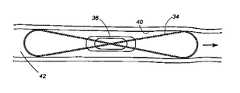
- FIG. 1is an isometric view of a first embodiment of an implant assembly of this invention having two opposed wire loops.
- FIG. 2is a top view of the implant assembly of FIG. 1 .
- FIG. 3is a side view of the implant assembly of FIG. 1 fixed in a vessel.
- FIG. 4is a top view of a second embodiment of an implant assembly of the invention having opposed wire loops.
- FIG. 5is a top view of the implant assembly of FIG. 4 fixed in a vessel.
- FIG. 6is a top view of a third embodiment of an implant assembly of this invention having two opposed wire loops.
- FIG. 7is an isometric view of the implant assembly of FIG. 6 .
- FIG. 8is an isometric view of the implant assembly of FIG. 6 fixed in a vessel.
- FIG. 9is a top view of a fourth embodiment of an implant assembly of this invention having opposed wire loops.
- FIG. 10is an isometric view of the implant assembly of FIG. 9 .
- FIG. 11is an isometric view of the implant assembly of FIG. 9 fixed in a vessel.
- FIG. 12is an isometric view of a fourth embodiment of an implant assembly of this invention having a radial wire array expansible structure.
- FIG. 13is an isometric view of a fifth embodiment of an implant assembly having an alternative radial wire array.
- FIG. 14is an isometric view of a sixth embodiment of an implant assembly of this invention having two radial wire array expansible structures.
- FIG. 15is an isometric view of the implant assembly of FIG. 12 fixed in a vessel.
- FIG. 16is an isometric view of a seventh embodiment of an implant assembly of this invention having a radial wire array expansible structure.
- FIG. 17is an isometric view of the implant assembly of FIG. 16 fixed in a vessel.
- FIG. 18is an isometric view of an eighth embodiment of an implant assembly of this invention having a daisy petal wire expansible structure.
- FIG. 19is an isometric view of a ninth embodiment of an implant assembly of this invention having a daisy petal expansible structure on each end of an intracorporeal device.
- FIG. 20is an isometric view of a tenth embodiment of an implant assembly of this invention having a daisy petal wire expansible structure.
- FIG. 21is an isometric view of an eleventh embodiment of an implant assembly of this invention having a daisy petal wire expansible structure.
- FIG. 22is an isometric view of the implant assembly of FIG. 18 fixed in a vessel.
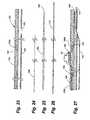
- FIG. 23is a side cross-sectional view of a delivery apparatus of this invention.
- FIG. 24is a side view of a tether wire of the delivery apparatus of this invention.
- FIG. 25is a side view of a core wire of the delivery apparatus of this invention.
- FIG. 26is a side view of a guidewire of the delivery apparatus of this invention.
- FIG. 27is a side cross-sectional view of the delivery system of this invention comprising the components of FIGS. 23-26 .
- FIG. 28is a side cross-sectional view of the delivery system of this invention comprising the components of FIGS. 23-26 and the intracorporeal device of FIGS. 4 and 5 .
- FIG. 29is a side cross-sectional view of a delivery system of this invention comprising the intracorporeal device of FIGS. 18 and 20 .
- FIG. 30is an isometric view of the components shown in FIG. 29 .
- An implant assembly of this inventionincludes an intracorporeal device and an anchoring structure used to stabilize the intracorporeal device in the body, such as in a vessel.
- Delivery systems of this inventionare used to deploy and secure the implant assembly in a desired location in a vessel and include a delivery apparatus and an implant assembly.
- the intracorporeal devicemay be a pressure sensor, further described below.
- the anchoring structuremay be a structure capable of being introduced into the body via a delivery apparatus, such as a catheter, and then lodging within the vessel.
- Anchoring structures of this inventionmay be formed from metal or polymer, and may be in the form of a wire structure. Wire structures of this invention may include structure including opposed wire loops, radial wire array structures, and daisy petal structures, all further described below.
- All of the implant assemblies of this inventionobstruct approximately 50% or less of the cross-sectional area of the vessel in which it resides. Preferably, the implant assemblies obstruct 20% or less of the cross-sectional area of the vessel. Minimizing the obstruction of flow within the vessel allows the sensor to remain secured in position in a vessel without creating significant impact to the flow within the vessel.
- the intracorporeal device used to couple to the anchoring structures described belowhas a width of about 0.5 to about 4 mm, a height of about 0.5 to about 4 mm, and a length of about 0.5 to about 12 mm.
- the intracorporeal devicehas a width of 3.2 mm, a height of 2 mm, and a length of 10 mm. Examples of such devices are disclosed in commonly owned U.S. Pat. No. 6,855,115; and in co-pending, commonly owned applications Ser. Nos. 10/054,671; 10/886,829; 10/215,377; 10/215,379; 10/943,772 incorporated herein by reference.
- One implant assembly of this invention adapted for deployment and fixation within a vesselincludes an intracorporeal device and a wire structure having wire loops.
- the loopsmay traverse the length of the device or may be limited to one end of the device.
- an implant assembly 30 having a double loop structure 32includes a wire 34 attached to an intracorporeal device 36 at an anchor point (not shown).
- the wire 34is threaded through an end of the intracorporeal device 36 at a hole 38 .
- the anchor pointis formed by crimping a piece of metal to the wire and trimming off the excess wire, so that the crimped-on metal comprises the terminal end of the wire. This metal end also provides a radiopaque marker for fluoroscopic visualization of the device.
- the wire 34is threaded through the hole 38 on one end of the device, the wire is pulled with sufficient force to bury the anchor fixedly into the silicone coating of the intracorporeal device.
- the wire 34is then looped around to form the double loop configuration 32 .
- the second free endis also inserted under the coating and the anchor is buried in the coating to fix the anchor. In this manner, the ends of the wire are inserted under the coating of the intracorporeal device 36 and away from the sensor.
- the wire 34contacts the inner surface 40 of the wall of the vessel 42 , as shown in FIG. 3 .
- the arrow shown in FIG. 3indicates the direction of blood flow.
- the loop structurehas a “figure eight” shape.
- Implant assembly 31 having a double loop structure 33includes a wire 35 attached to sensor body 37 at an anchor point (not shown). The ends of the wire 35 are inserted under the coating of the sensor body 37 and away from the sensor as described in the previous example. Upon deployment of the implant assembly 31 , the wire 35 contacts the inner surface 41 of the wall of the vessel 43 , as shown in FIG. 5 .
- the arrow shown in FIG. 5indicates the direction of blood flow.
- the opposed loop structureis constructed of a single wire. In an alternative embodiment, the opposed loop structure is constructed of more than one wire.
- the structureincludes a plurality of wire loops 44 encircling an intracorporeal device 46 .
- the wire 48is threaded from end to end in a circular fashion, through one or more holes 50 located on each end of the sensor, to form the loops.
- the free end of the wireis used to create another anchor as described above.
- the second free endis then pulled back into the silicone coating with sufficient force to bury the second anchor fixedly in the silicone coating.
- the location of the second anchorlies on the opposite side of the sensor from the first anchor.
- the wire loopsare then arranged by mechanical means to create wire members that are substantially evenly distributed radially around the longitudinal axis of the sensor.
- the wire loopsmay be attached to the intracorporeal device 40 by threading through one hole 50 located near the edge of the device 46 as referenced to the longitudinal axis of the device 46 , as shown in FIG. 6 .
- the wire loopsmay be attached to the intracorporeal device 46 by threading through two holes 50 located near each edge of the device 46 , as shown in FIG. 9 .
- each configurationcontacts the inner surface 52 of the wall of the vessel 54 , as shown in FIGS. 8 and 11 .
- the arrows shown in FIGS. 8 and 11indicate the direction of blood flow.
- the wire diameter of the anchoring structurelies in the range of about 0.001 to about 0.015 inches.
- the material comprising the wirecan be any biocompatible material known in the art that possess sufficient elastic properties to be useful for the purpose at hand.
- the materialmay be a metal, such as nitinol, stainless steel, eligiloy, cobalt chrome alloys, or any other suitable metal.
- the biocompatible wireis coated with a dielectric material, such as, but not limited to, PTFE, polyurethane, parylene and diamond-like carbon (DLC) so as not to pose electromagnetic interference with the function of the intracorporeal device when the device comprises an RF sensor.
- a dielectric materialsuch as, but not limited to, PTFE, polyurethane, parylene and diamond-like carbon (DLC)
- FIGS. 12-17Another implant assembly according to this invention includes an intracorporeal device and an anchoring structure having a substantially parabolic-shaped profile, as shown in FIGS. 12-17 .
- an implant assembly 58includes an intracorporeal device 60 and a radial wire array 62 , which includes wire members 64 .
- Members 62may be attached to the intracorporeal device 60 at an anchor point, as described above.
- the radial wire array 62can be attached to the intracorporeal device 60 by threading the wire members 64 through one hole 66 located near the edge of the intracorporeal device 60 , as shown in FIG. 12 .
- the radial wire array 62can be attached to the intracorporeal device 60 by threading the wire members 64 through two holes 66 located near the edge of the device 60 as shown in FIG. 16 .
- the wire endis press-fit into a silicone coating covering the surface of the device to secure the end.
- the radial wire arraymay be formed by crimping a piece of metal at a point substantially midlength of the wire bundle and then threading the wire bundle through a hole near the edge of the intracorporeal device, thus lodging the anchor within the silicone material filling the hole.
- the anchorsecures the end of the radial wire between the surface of the device and the silicone coating covering the surface of the device.
- the crimped metal anchorprovides a radiopaque marker for fluoroscopic visualization of the device.
- the radial wire arrayis self-supporting, as a result of the physical properties of the material.
- the radial wire arraymay include a mechanical expansion structure to support the array to expand and contact the vessel wall.
- a catheter balloonmay be inflated to cause a wire structure to attain and maintain an expanded configuration.
- the intracorporeal device 60can be positioned outside a radial wire array 62 so that one end 72 of the intracorporeal device 60 is fixed to a point at or near the apex of the radial wire array 62 , as shown in FIG. 12 .
- the intracorporeal device 60can also be positioned inside the radial wire array so that one end of the device is fixed to a point at or near the apex of the radial wire array, as shown in FIG. 13 .
- the intracorporeal devicemay have two radial wire arrays 62 attached to the intracorporeal device 60 so that one end of the intracorporeal device is attached to the apex on the exterior of one of the radial wire arrays and the opposing end of said device is attached to the apex on the interior of the second radial wire array, as shown in FIG. 14 .
- the ends of the radial wire arraymay terminate with barbs or hooks 74 as shown in FIGS. 12-15 .
- the hooks 74are turned outwardly with respect to the longitudinal axis of the parabolic profile of the radial wire array 62 .
- the hooks or barbs disposed on the distal ends of the members of the radial wire arrayprevent the implant assembly from being dislodged after the hooks or barbs have engaged the walls of the vessel, as shown in FIG. 15 .
- the hook or barb featuresshould be of sufficient size to achieve adequate device fixation without perforation or dissection of the vessel wall.
- the fit of the radial wires within the walls of the vesselmay fix the device in the vessel without the use of hooks or barbs, as shown in FIG. 17 .
- the arrows shown in FIGS. 15 and 17indicate the direction of blood flow.
- the wire diameter of the radial wire arraylies in the range of about 0.001 to about 0.015 inches.
- the material comprising the wirecan be any biocompatible metal known in the art that possess sufficient elastic properties to be useful for the purpose at hand.
- the metalmay be nitinol, stainless steel, eligiloy, cobalt chrome alloys, or any other suitable metal.
- the biocompatible wirecan optionally be coated with PTFE so as not to pose electromagnetic interference with the function of the intracorporeal device when the device comprises an RF sensor.
- An implant assemblyincludes an intracorporeal device and an anchoring structure having a daisy petal shape, as shown in FIGS. 18-22 .
- the implant assembly 76includes an intracorporeal device 78 and a daisy petal wire structure 80 , which contacts the inner surface 82 of the wall of the vessel 84 , as shown in FIG. 22 .
- the arrow shown in FIG. 22indicates the direction of blood flow.
- the intracorporeal devicehas a proximal end 86 , a distal end 88 , and a longitudinal axis 90 , as shown in FIG. 18 .
- the daisy petal wire structure 80is positioned so that the structure lies in a plane normal to the longitudinal axis 90 of the intracorporeal device 78 .
- the daisy petal wire structure 80may be constructed of a single wire or of a plurality of wires. As shown in FIG. 18 , the daisy petal wire structure 80 includes a plurality of lobes 92 . The structure may have either an even or an odd number of lobes.
- the intracorporeal device 78may have two daisy petal wire structures 80 attached to the device on opposing ends 94 , 96 and located along the longitudinal axis 90 .
- the daisy petal wire structure 80may be attached to the intracorporeal device 78 by threading through a hole 98 located near the edge of the device 78 , as shown in FIG. 20 .
- the daisy petal wire structure 80may be attached to the intracorporeal device 78 by threading through two holes 98 located near the edge of the device 78 , as shown in FIGS. 18 and 21 .
- the daisy petal wire structure 80is attached to the intracorporeal device at an anchor point.
- the anchoris made by crimping a piece of metal to the wire and trimming off the excess wire, so that the crimped-on metal comprises the terminal end of the wire.
- This metal endalso provides a radiopaque marker for fluoroscopic visualization of the device.
- the wireis threaded through the hole or holes on one end of the sensor and the wire is pulled with sufficient force to bury the anchor fixedly into the silicone coating.
- the wireis then threaded from top to bottom in a circular fashion, through the hole or holes located on the end of the sensor, to form the daisy petal structure.
- the free end of the wireis used to create another anchor.
- the second free endis then pulled back into the silicone coating with sufficient force to bury the second anchor fixedly in the silicone coating.
- the wire loopsare then arranged by mechanical means to create wire members that are substantially evenly distributed radially around the longitudinal axis of the sensor.
- the wire diameter in the present inventionlies in the range of about 0.001 to about 0.015 inches.
- the material comprising the wirecan be any biocompatible material known in the art that possess sufficient physical properties to be useful for the purpose at hand and such materials are obvious to one skilled in the art.
- the materialis a metal selected from the group comprising nitinol, stainless steel, eligiloy, and cobalt chrome alloys.
- the biocompatible wiremay be coated with a dielectric material such as, but not limited to, PTFE, polyurethane, parylene and diamond-like carbon (DLC) so as not to pose electromagnetic interference with the function of the intracorporeal device when the device comprises an RF sensor.
- a dielectric materialsuch as, but not limited to, PTFE, polyurethane, parylene and diamond-like carbon (DLC)
- the delivery apparatus 100includes a main lumen 102 adapted to accept a core wire 104 ( FIG. 25 ) and a secondary lumen comprising a first section 106 A and a second section 106 B and adapted to accept a tether wire 108 ( FIG. 24 ).
- the core wire 104shown in FIG. 25 , provides columnar stiffness to the delivery assembly 100 , thereby facilitating advancement of the delivery assembly through the vasculature.
- the core wire 104also prevents buckling of the delivery assembly 100 when the tether wire is pulled proximally during the implant assembly deployment.
- the core wire 104has a decreasing diameter toward its distal end 105 , providing gradual decrease in stiffness from the proximal to the distal end of the delivery assembly 100 .
- the tapered core wire 104can extend past a guidewire aperture 112 in order to reinforce a potential kink point in the delivery apparatus 100 and to facilitate the advancement of the guidewire into the vasculature.
- the core wire 104is fixed in the main lumen 102 using adhesive, thermocompression, or any other suitable fixation mechanism. Fixation of the core wire 104 prevents the core wire from being disturbed by the guidewire 110 , shown in FIG. 26 , when the guidewire 110 enters the main lumen 102 of the delivery apparatus 100 at the guidewire aperture 112 as shown in FIG. 27 .
- the tether wire 108shown in FIG. 24 , is slidably positioned within the first secondary lumen portion 106 A and exits the first secondary lumen portion at an aperture 114 in the wall of the device. As shown in FIG. 27 , the tether wire 108 then passes through the coating of the intracorporeal device 30 , exiting on the opposite side of the device. The free end 118 of the tether wire 108 enters the second portion 106 B of the secondary lumen at the aperture 109 .
- FIG. 28shows an alternate embodiment of a delivery apparatus adapted to deploy the sensor 31 of FIGS. 4 and 5 . Because of the length of the wire loops 35 of the sensor 31 , the proximal and distal ends of the loops must be secured to the delivery apparatus so that, when the delivery apparatus curves, the loops will follow the curvature of the delivery apparatus. Toward that end, the secondary lumen of the delivery apparatus of FIG. 28 is divided into four sections 106 A-D. The tether wire 108 exits the first section 106 A of the secondary lumen and passes over and through wire loops 55 to attach the implant assembly 51 to the delivery apparatus 100 . The tether wire then enters the second portion 106 B of the secondary lumen.
- the tether wirethen exits the second portion 106 B of the secondary lumen and passes through the coating of the sensor 31 .
- the tether wirethen enters the third portion 106 C of the secondary lumen.
- the tether wireexits the third portion 106 C of the secondary lumen, passes over the wire loop 35 , and enters the fourth section 106 D of the secondary lumen. Note that with the proximal and distal wire loops 35 thus secured to the delivery apparatus, it is optional as to whether to pass the tether wire 106 through the coating of the body of the sensor 31 .
- an outer sleeve 116may be provided to constrain an expansible structure 80 of an intracorporeal device 78 .
- the outer sleeve 118may be slidably positioned over the double lumen tube 118 .
- an intracorporeal devicemay be accomplished using either active or passive fixation.
- an intracorporeal deviceis delivered into the vessel and allowed to float in the blood stream until it lodges. After lodging in the vessel, blood flow is maintained due to the configuration of the device and its anchoring structure.
- an intracorporeal deviceincludes an anchoring structure that utilizes radial force to fix the device in the vessel. The radial force is released at a selected point of deployment. Preferably the anchoring structure exerts the minimum radial force that will hold the intracorporeal device in place. The radial force may also include the use of hooks or barbs to actively fix the device.
- the intracorporeal deviceembolizes without an anchor mechanism.
- a vessel introduceris positioned in the access site.
- the access site for the vessel introducermay be the right internal jugular vein, the subclavian artery, the right femoral vein, or any other suitable access site.
- a guidewireis placed in the vasculature and positioned across the desired deployment site with the aid of, e.g., a Swan-Ganz catheter, a diagnostic catheter or any other suitable catheter, such catheter being removed after the guidewire is in position.
- the delivery systemis loaded into the vessel introducer and navigated to the deployment site.
- the delivery system lengthcan be increased or decreased according to standard practice depending on the access site chosen.
- the deployment siteis a vessel, and may be any artery or arteriole in the pulmonary artery vasculature.
- the implant assemblyis deployed by pulling the tether wire proximally to disengage the implant assembly from the delivery apparatus.
- the implant assemblyis allowed to “float” in the vasculature until it reaches a bifurcation in the vasculature.
- the anchoring mechanismprohibits the implant assembly from progressing into smaller vessels, thereby lodging the sensor at a location that is immediately proximal to the bifurcation.
- the delivery assembly and guidewireare then removed from the body.
- an outer sleeveis provided to constrain an expansible structure so that sliding the outer sleeve proximally allows expansion of the expansible structure. If the expansible structure is a radial wire array without hooks or barbs, the implant assembly floats to the next bifurcation where it is lodged in place exactly as described in the previous example. If the radial wire array is equipped with hook or barb features, the implant assembly will remain fixed in the location at which it deployed. The delivery assembly and guidewire are then removed from the body.
- the embodiments described abovemay be employed with a wireless device, as shown in the Figures, or with a wired intracorporeal device.
Landscapes
- Health & Medical Sciences (AREA)
- Life Sciences & Earth Sciences (AREA)
- Molecular Biology (AREA)
- Surgery (AREA)
- Biophysics (AREA)
- Pathology (AREA)
- Engineering & Computer Science (AREA)
- Biomedical Technology (AREA)
- Heart & Thoracic Surgery (AREA)
- Medical Informatics (AREA)
- Cardiology (AREA)
- Physics & Mathematics (AREA)
- Animal Behavior & Ethology (AREA)
- General Health & Medical Sciences (AREA)
- Public Health (AREA)
- Veterinary Medicine (AREA)
- Hematology (AREA)
- Vascular Medicine (AREA)
- Physiology (AREA)
- Prostheses (AREA)
Abstract
Description
Claims (26)
Priority Applications (9)
| Application Number | Priority Date | Filing Date | Title |
|---|---|---|---|
| US11/180,840US8021307B2 (en) | 2005-03-03 | 2005-07-13 | Apparatus and method for sensor deployment and fixation |
| US11/232,668US8118749B2 (en) | 2005-03-03 | 2005-09-22 | Apparatus and method for sensor deployment and fixation |
| AU2006218347AAU2006218347A1 (en) | 2005-03-03 | 2006-03-02 | Apparatus and method for sensor deployment and fixation |
| CA2599413ACA2599413C (en) | 2005-03-03 | 2006-03-02 | Apparatus and method for sensor deployment and fixation |
| EP06737153.4AEP1868496B1 (en) | 2005-03-03 | 2006-03-02 | Apparatus for sensor deployment and fixation |
| EP21169944.2AEP3884858A1 (en) | 2005-03-03 | 2006-03-02 | Apparatus and method for sensor deployment and fixation |
| PCT/US2006/007938WO2006094273A2 (en) | 2005-03-03 | 2006-03-02 | Apparatus and method for sensor deployment and fixation |
| US13/236,091US8355777B2 (en) | 2005-03-03 | 2011-09-19 | Apparatus and method for sensor deployment and fixation |
| US13/286,641US8353841B2 (en) | 2005-03-03 | 2011-11-01 | Apparatus and method for sensor deployment and fixation |
Applications Claiming Priority (3)
| Application Number | Priority Date | Filing Date | Title |
|---|---|---|---|
| US65835805P | 2005-03-03 | 2005-03-03 | |
| US66221005P | 2005-03-14 | 2005-03-14 | |
| US11/180,840US8021307B2 (en) | 2005-03-03 | 2005-07-13 | Apparatus and method for sensor deployment and fixation |
Related Child Applications (2)
| Application Number | Title | Priority Date | Filing Date |
|---|---|---|---|
| US11/232,668Continuation-In-PartUS8118749B2 (en) | 2005-03-03 | 2005-09-22 | Apparatus and method for sensor deployment and fixation |
| US13/236,091ContinuationUS8355777B2 (en) | 2005-03-03 | 2011-09-19 | Apparatus and method for sensor deployment and fixation |
Publications (2)
| Publication Number | Publication Date |
|---|---|
| US20060200030A1 US20060200030A1 (en) | 2006-09-07 |
| US8021307B2true US8021307B2 (en) | 2011-09-20 |
Family
ID=36944996
Family Applications (2)
| Application Number | Title | Priority Date | Filing Date |
|---|---|---|---|
| US11/180,840Active2028-11-29US8021307B2 (en) | 2005-03-03 | 2005-07-13 | Apparatus and method for sensor deployment and fixation |
| US13/236,091Expired - LifetimeUS8355777B2 (en) | 2005-03-03 | 2011-09-19 | Apparatus and method for sensor deployment and fixation |
Family Applications After (1)
| Application Number | Title | Priority Date | Filing Date |
|---|---|---|---|
| US13/236,091Expired - LifetimeUS8355777B2 (en) | 2005-03-03 | 2011-09-19 | Apparatus and method for sensor deployment and fixation |
Country Status (1)
| Country | Link |
|---|---|
| US (2) | US8021307B2 (en) |
Cited By (38)
| Publication number | Priority date | Publication date | Assignee | Title |
|---|---|---|---|---|
| US8682450B2 (en) | 2012-07-31 | 2014-03-25 | Pacesetter, Inc. | Systems and methods for controlling neurostimulation of acupuncture sites using an implantable cardiac rhythm management device |
| US9049995B2 (en) | 2012-01-12 | 2015-06-09 | Pacesetter, Inc. | System and method for detecting pulmonary congestion based on stroke volume using an implantable medical device |
| US9301702B2 (en) | 2012-11-19 | 2016-04-05 | Pacesetter, Inc. | Systems and methods for exploiting pulmonary artery pressure obtained from an implantable sensor to detect cardiac rhythm irregularities |
| US9333365B2 (en) | 2010-07-30 | 2016-05-10 | Medtronic, Inc. | Antenna for an implantable medical device |
| US9566442B2 (en) | 2012-11-19 | 2017-02-14 | Pacesetter, Inc. | Systems and methods for using pulmonary artery pressure from an implantable sensor to detect mitral regurgitation and optimize pacing delays |
| US9610450B2 (en) | 2010-07-30 | 2017-04-04 | Medtronics, Inc. | Antenna for an implantable medical device |
| US10105103B2 (en) | 2013-04-18 | 2018-10-23 | Vectorious Medical Technologies Ltd. | Remotely powered sensory implant |
| WO2018195430A1 (en) | 2017-04-20 | 2018-10-25 | Endotronix, Inc. | Anchoring system for a catheter delivered device |
| US10205488B2 (en) | 2013-04-18 | 2019-02-12 | Vectorious Medical Technologies Ltd. | Low-power high-accuracy clock harvesting in inductive coupling systems |
| US10206592B2 (en) | 2012-09-14 | 2019-02-19 | Endotronix, Inc. | Pressure sensor, anchor, delivery system and method |
| US10213115B2 (en) | 2008-10-31 | 2019-02-26 | Medtronic, Inc. | Method and apparatus to detect ischemia with a pressure sensor |
| US10687716B2 (en) | 2012-11-14 | 2020-06-23 | Vectorious Medical Technologies Ltd. | Drift compensation for implanted capacitance-based pressure transducer |
| US10687794B2 (en) | 2016-12-20 | 2020-06-23 | Medtronic, Inc. | Delivery catheter for implantable medical device |
| US10806352B2 (en) | 2016-11-29 | 2020-10-20 | Foundry Innovation & Research 1, Ltd. | Wireless vascular monitoring implants |
| US10806428B2 (en) | 2015-02-12 | 2020-10-20 | Foundry Innovation & Research 1, Ltd. | Implantable devices and related methods for heart failure monitoring |
| US10874349B2 (en) | 2015-05-07 | 2020-12-29 | Vectorious Medical Technologies Ltd. | Deploying and fixating an implant across an organ wall |
| US11039813B2 (en) | 2015-08-03 | 2021-06-22 | Foundry Innovation & Research 1, Ltd. | Devices and methods for measurement of Vena Cava dimensions, pressure and oxygen saturation |
| US11179048B2 (en)* | 2005-06-21 | 2021-11-23 | St. Jude Medical Luxembourg Holdings Ii S.A.R.L. (“Sjm Lux 11”) | System for deploying an implant assembly in a vessel |
| US11206992B2 (en) | 2016-08-11 | 2021-12-28 | Foundry Innovation & Research 1, Ltd. | Wireless resonant circuit and variable inductance vascular monitoring implants and anchoring structures therefore |
| US11206988B2 (en) | 2015-12-30 | 2021-12-28 | Vectorious Medical Technologies Ltd. | Power-efficient pressure-sensor implant |
| US11344210B2 (en) | 2016-12-20 | 2022-05-31 | Medtronic, Inc. | Delivery catheter for implantable medical device |
| WO2023018922A1 (en) | 2021-08-13 | 2023-02-16 | 3Ive Labs, Llc | Negative pressure therapy system and methods |
| US11622684B2 (en) | 2017-07-19 | 2023-04-11 | Endotronix, Inc. | Physiological monitoring system |
| US11701018B2 (en) | 2016-08-11 | 2023-07-18 | Foundry Innovation & Research 1, Ltd. | Wireless resonant circuit and variable inductance vascular monitoring implants and anchoring structures therefore |
| US11752300B2 (en) | 2015-07-20 | 2023-09-12 | Roivios Limited | Catheter device and method for inducing negative pressure in a patient's bladder |
| US11779238B2 (en) | 2017-05-31 | 2023-10-10 | Foundry Innovation & Research 1, Ltd. | Implantable sensors for vascular monitoring |
| US11896785B2 (en) | 2015-07-20 | 2024-02-13 | Roivios Limited | Ureteral and bladder catheters and methods of inducing negative pressure to increase renal perfusion |
| US11904121B2 (en) | 2015-07-20 | 2024-02-20 | Roivios Limited | Negative pressure therapy system |
| US11918754B2 (en) | 2015-07-20 | 2024-03-05 | Roivios Limited | Ureteral and bladder catheters and methods of inducing negative pressure to increase renal perfusion |
| WO2024059244A1 (en) | 2022-09-15 | 2024-03-21 | 3Ive Labs, Llc | Negative pressure therapy devices, systems, and treatment methods with indwelling urinary catheters |
| US11944495B2 (en) | 2017-05-31 | 2024-04-02 | Foundry Innovation & Research 1, Ltd. | Implantable ultrasonic vascular sensor |
| WO2024073322A2 (en) | 2022-09-30 | 2024-04-04 | Tc1 Llc | Tandem interlace delivery catheter for delivering an intracorporeal sensor |
| US12059543B2 (en) | 2017-08-25 | 2024-08-13 | Roivios Limited | Indwelling pump for facilitating removal of urine from the urinary tract |
| US12064567B2 (en) | 2015-07-20 | 2024-08-20 | Roivios Limited | Percutaneous urinary catheter |
| WO2024172917A1 (en) | 2023-02-14 | 2024-08-22 | Tc1 Llc | Implantable pressure sensor drift detection |
| US12076225B2 (en) | 2015-07-20 | 2024-09-03 | Roivios Limited | Ureteral catheters, bladder catheters, systems, kits and methods for inducing negative pressure to increase renal function |
| WO2024263311A1 (en) | 2023-06-20 | 2024-12-26 | Tc1 Llc | Sensor anchor loop configurations for lodging an implantable wireless sensor in a lumen |
| US12268493B2 (en) | 2016-08-11 | 2025-04-08 | Foundry Innovation & Research 1, Ltd. | Systems and methods for self-directed patient fluid management |
Families Citing this family (27)
| Publication number | Priority date | Publication date | Assignee | Title |
|---|---|---|---|---|
| US8388553B2 (en) | 2004-11-04 | 2013-03-05 | Smith & Nephew, Inc. | Cycle and load measurement device |
| US8021307B2 (en) | 2005-03-03 | 2011-09-20 | Cardiomems, Inc. | Apparatus and method for sensor deployment and fixation |
| US8118749B2 (en)* | 2005-03-03 | 2012-02-21 | Cardiomems, Inc. | Apparatus and method for sensor deployment and fixation |
| AU2006282828B2 (en) | 2005-08-23 | 2013-01-31 | Smith & Nephew, Inc | Telemetric orthopaedic implant |
| US20070112423A1 (en)* | 2005-11-16 | 2007-05-17 | Chu Jack F | Devices and methods for treatment of venous valve insufficiency |
| US9445720B2 (en) | 2007-02-23 | 2016-09-20 | Smith & Nephew, Inc. | Processing sensed accelerometer data for determination of bone healing |
| US8570187B2 (en) | 2007-09-06 | 2013-10-29 | Smith & Nephew, Inc. | System and method for communicating with a telemetric implant |
| US8704124B2 (en) | 2009-01-29 | 2014-04-22 | Smith & Nephew, Inc. | Low temperature encapsulate welding |
| US8465436B2 (en) | 2010-04-27 | 2013-06-18 | Medtronic Vascular, Inc. | Endoluminal implant with locking and centering fixation system |
| US8475372B2 (en) | 2010-10-29 | 2013-07-02 | Medtronic Vascular, Inc. | Implantable medical sensor and fixation system |
| US8864676B2 (en) | 2010-10-29 | 2014-10-21 | Medtronic Vascular, Inc. | Implantable medical sensor and fixation system |
| US8963708B2 (en) | 2011-01-13 | 2015-02-24 | Sensurtec, Inc. | Breach detection in solid structures |
| US8727996B2 (en) | 2011-04-20 | 2014-05-20 | Medtronic Vascular, Inc. | Delivery system for implantable medical device |
| US9351648B2 (en) | 2012-08-24 | 2016-05-31 | Medtronic, Inc. | Implantable medical device electrode assembly |
| GB201616092D0 (en) | 2016-09-21 | 2016-11-02 | Imp Innovations Ltd | Apparatus for securing a device in a vascular lumen |
| CN112437679B (en)* | 2018-09-11 | 2023-02-03 | 朝日英达科株式会社 | Intracorporeal indwelling equipment |
| US12357792B2 (en) | 2019-01-04 | 2025-07-15 | Shifamed Holdings, Llc | Internal recharging systems and methods of use |
| WO2020206366A1 (en)* | 2019-04-05 | 2020-10-08 | Shifamed Holdings, Llc | Delivery devices, systems, and methods of use for positioning and using hemodynamic monitoring systems |
| JP7648607B2 (en) | 2019-09-09 | 2025-03-18 | シファメド・ホールディングス・エルエルシー | ADJUSTABLE SHUNTS AND ASSOCIATED SYSTEMS AND METHODS - Patent application |
| US11253685B2 (en) | 2019-12-05 | 2022-02-22 | Shifamed Holdings, Llc | Implantable shunt systems and methods |
| WO2021217055A1 (en) | 2020-04-23 | 2021-10-28 | Shifamed Holdings, Llc | Intracardiac sensors with switchable configurations and associated systems and methods |
| JP2023540220A (en) | 2020-08-25 | 2023-09-22 | シファメド・ホールディングス・エルエルシー | Adjustable interatrial flow diverter and related systems and methods |
| JP2023540219A (en)* | 2020-08-25 | 2023-09-22 | カナリー メディカル スウィッツァーランド アクチェンゲゼルシャフト | Occlusion device with detection function |
| EP4243915A4 (en) | 2020-11-12 | 2024-08-07 | Shifamed Holdings, LLC | ADJUSTABLE IMPLANTABLE DEVICES AND RELATED METHODS |
| US12090290B2 (en) | 2021-03-09 | 2024-09-17 | Shifamed Holdings, Llc | Shape memory actuators for adjustable shunting systems, and associated systems and methods |
| WO2025136641A1 (en) | 2023-12-20 | 2025-06-26 | Tc1 Llc | Implantable sensor signal lock through single ping transmission |
| WO2025136640A1 (en) | 2023-12-22 | 2025-06-26 | Tc1 Llc | Systems and methods for wavelet transformation based dicrotic notch extraction and arrhythmia detection |
Citations (117)
| Publication number | Priority date | Publication date | Assignee | Title |
|---|---|---|---|---|
| US2769863A (en) | 1953-03-27 | 1956-11-06 | Automatic Elect Lab | Rotary finder with graded multiple |
| US3867950A (en) | 1971-06-18 | 1975-02-25 | Univ Johns Hopkins | Fixed rate rechargeable cardiac pacemaker |
| US3942382A (en) | 1973-10-17 | 1976-03-09 | Siemens Aktiengesellschaft | Pressure transducer |
| US3958558A (en) | 1974-09-16 | 1976-05-25 | Huntington Institute Of Applied Medical Research | Implantable pressure transducer |
| US4026276A (en) | 1976-04-05 | 1977-05-31 | The Johns Hopkins University | Intracranial pressure monitor |
| US4127110A (en) | 1976-05-24 | 1978-11-28 | Huntington Institute Of Applied Medical Research | Implantable pressure transducer |
| US4206762A (en) | 1976-06-21 | 1980-06-10 | Cosman Eric R | Telemetric differential pressure sensing method |
| US4207903A (en) | 1978-04-28 | 1980-06-17 | Medtronic, Inc. | Device for screwing body tissue electrode into body tissue |
| USRE30366E (en) | 1970-09-21 | 1980-08-12 | Rasor Associates, Inc. | Organ stimulator |
| US4237900A (en) | 1979-02-14 | 1980-12-09 | Pacesetter Systems, Inc. | Implantable calibration means and calibration method for an implantable body transducer |
| US4354506A (en) | 1980-01-17 | 1982-10-19 | Naganokeiki Seisakujo Company, Ltd. | Intracranial pressure gauge |
| US4378809A (en) | 1978-04-13 | 1983-04-05 | Cosman Eric R | Audio-telemetric pressure sensing systems and methods |
| CA1158061A (en) | 1980-06-02 | 1983-12-06 | Christopher R. Brown | Industrial process control instrument employing a resonant sensor |
| US4485813A (en) | 1981-11-19 | 1984-12-04 | Medtronic, Inc. | Implantable dynamic pressure transducer system |
| US4494950A (en) | 1982-01-19 | 1985-01-22 | The Johns Hopkins University | Plural module medication delivery system |
| US4521684A (en) | 1982-02-22 | 1985-06-04 | The Foxboro Company | Optical measurement system with light-driven vibrating sensor element |
| US4596563A (en) | 1983-06-09 | 1986-06-24 | Cordis Corporation | Thin-walled multi-layered catheter having a fuseless tip |
| US4713540A (en) | 1985-07-16 | 1987-12-15 | The Foxboro Company | Method and apparatus for sensing a measurand |
| US4718425A (en) | 1985-05-29 | 1988-01-12 | Mitsui Toatsu Chemicals Incorporated | Catheter with pressure sensor |
| US4796641A (en) | 1987-07-06 | 1989-01-10 | Data Sciences, Inc. | Device and method for chronic in-vivo measurement of internal body pressure |
| US4815472A (en) | 1987-06-01 | 1989-03-28 | The Regents Of The University Of Michigan | Multipoint pressure-sensing catheter system |
| US4846191A (en) | 1988-05-27 | 1989-07-11 | Data Sciences, Inc. | Device for chronic measurement of internal body pressure |
| US4890623A (en) | 1988-03-14 | 1990-01-02 | C. R. Bard, Inc. | Biopotential sensing device and method for making |
| US4899752A (en) | 1987-10-06 | 1990-02-13 | Leonard Bloom | System for and method of therapeutic stimulation of a patient's heart |
| US4913147A (en) | 1986-09-23 | 1990-04-03 | Siemens Aktiengesellschaft | Heart pacemaker system with shape-memory metal components |
| US4934369A (en) | 1987-01-30 | 1990-06-19 | Minnesota Mining And Manufacturing Company | Intravascular blood parameter measurement system |
| US4987897A (en) | 1989-09-18 | 1991-01-29 | Medtronic, Inc. | Body bus medical device communication system |
| US5115128A (en) | 1989-01-06 | 1992-05-19 | Lucas Industries Public Limited Companies | Signal extraction apparatus and method |
| US5113868A (en) | 1987-06-01 | 1992-05-19 | The Regents Of The University Of Michigan | Ultraminiature pressure sensor with addressable read-out circuit |
| US5129394A (en) | 1991-01-07 | 1992-07-14 | Medtronic, Inc. | Method and apparatus for controlling heart rate in proportion to left ventricular pressure |
| US5165289A (en) | 1990-07-10 | 1992-11-24 | Johnson Service Company | Resonant mechanical sensor |
| US5181423A (en) | 1990-10-18 | 1993-01-26 | Hottinger Baldwin Messtechnik Gmbh | Apparatus for sensing and transmitting in a wireless manner a value to be measured |
| US5192314A (en) | 1991-12-12 | 1993-03-09 | Daskalakis Michael K | Synthetic intraventricular implants and method of inserting |
| US5207103A (en) | 1987-06-01 | 1993-05-04 | Wise Kensall D | Ultraminiature single-crystal sensor with movable member |
| EP0337035B1 (en) | 1987-04-13 | 1993-11-18 | Cardiac Pacemakers, Inc. (a Minnesota corporation) | Soluble covering for cardiac pacing electrode |
| US5265606A (en) | 1990-07-23 | 1993-11-30 | C. R. Bard, Inc. | System and technique for measuring blood characteristics by centering a sensor in an artery |
| US5353800A (en) | 1992-12-11 | 1994-10-11 | Medtronic, Inc. | Implantable pressure sensor lead |
| US5373852A (en) | 1993-06-25 | 1994-12-20 | The Regents Of The University Of California | Monitoring uterine contractions by radiotelemetric transmission |
| US5411551A (en) | 1992-08-05 | 1995-05-02 | Ultrasonic Sensing And Monitoring Systems, Inc. | Stent assembly with sensor |
| US5431171A (en) | 1993-06-25 | 1995-07-11 | The Regents Of The University Of California | Monitoring fetal characteristics by radiotelemetric transmission |
| US5440300A (en) | 1992-11-25 | 1995-08-08 | Simmonds Precision Products, Inc. | Smart structure with non-contact power and data interface |
| US5487760A (en) | 1994-03-08 | 1996-01-30 | Ats Medical, Inc. | Heart valve prosthesis incorporating electronic sensing, monitoring and/or pacing circuitry |
| US5497099A (en) | 1991-09-06 | 1996-03-05 | Engine Control Systems Ltd. | Antenna system for soot detecting |
| US5515041A (en) | 1993-06-14 | 1996-05-07 | Simmonds Precision Products Inc. | Composite shaft monitoring system |
| US5535752A (en) | 1995-02-27 | 1996-07-16 | Medtronic, Inc. | Implantable capacitive absolute pressure and temperature monitor system |
| US5551427A (en) | 1995-02-13 | 1996-09-03 | Altman; Peter A. | Implantable device for the effective elimination of cardiac arrhythmogenic sites |
| US5566676A (en) | 1992-12-11 | 1996-10-22 | Siemens Medical Systems, Inc. | Pressure data acquisition device for a patient monitoring system |
| US5593430A (en) | 1995-01-27 | 1997-01-14 | Pacesetter, Inc. | Bus system for interconnecting an implantable medical device with a plurality of sensors |
| US5600245A (en) | 1993-10-08 | 1997-02-04 | Hitachi, Ltd. | Inspection apparatus using magnetic resonance |
| US5626630A (en) | 1994-10-13 | 1997-05-06 | Ael Industries, Inc. | Medical telemetry system using an implanted passive transponder |
| US5686841A (en) | 1992-11-30 | 1997-11-11 | Stolar, Inc. | Apparatus and method for the detection and measurement of liquid water and ice layers on the surfaces of solid materials |
| US5695155A (en) | 1995-09-21 | 1997-12-09 | Hughes Aircraft Company | Resonator-based, surface-condition sensor |
| US5702427A (en) | 1996-03-28 | 1997-12-30 | Medtronic, Inc. | Verification of capture using pressure waves transmitted through a pacing lead |
| US5713917A (en) | 1995-10-30 | 1998-02-03 | Leonhardt; Howard J. | Apparatus and method for engrafting a blood vessel |
| US5723791A (en) | 1993-09-28 | 1998-03-03 | Defelsko Corporation | High resolution ultrasonic coating thickness gauge |
| US5722414A (en) | 1993-11-09 | 1998-03-03 | Medwave, Inc. | Continuous non-invasive blood pressure monitoring system |
| US5743267A (en) | 1995-10-19 | 1998-04-28 | Telecom Medical, Inc. | System and method to monitor the heart of a patient |
| US5796827A (en) | 1996-11-14 | 1998-08-18 | International Business Machines Corporation | System and method for near-field human-body coupling for encrypted communication with identification cards |
| US5807265A (en) | 1996-01-09 | 1998-09-15 | Kabushiki Kaisha Tokai Rika Denki Seisakusho | Catheter having pressure detecting ability |
| US5836886A (en) | 1995-11-01 | 1998-11-17 | Kabushiki Kaisha Tokai Rika Denki Seisakusho | Catheter having a sensor |
| US5860938A (en) | 1996-03-07 | 1999-01-19 | Scimed Life Systems, Inc. | Medical pressure sensing guide wire |
| US5899927A (en) | 1996-03-28 | 1999-05-04 | Medtronic, Inc. | Detection of pressure waves transmitted through catheter/lead body |
| US5935084A (en) | 1997-09-30 | 1999-08-10 | Johnson & Johnson Professional, Inc. | Inflatable pressure indicator |
| US5942991A (en) | 1995-06-06 | 1999-08-24 | Diversified Technologies, Inc. | Resonant sensor system and method |
| US5967986A (en) | 1997-11-25 | 1999-10-19 | Vascusense, Inc. | Endoluminal implant with fluid flow sensing capability |
| US6015386A (en) | 1998-05-07 | 2000-01-18 | Bpm Devices, Inc. | System including an implantable device and methods of use for determining blood pressure and other blood parameters of a living being |
| US6015387A (en) | 1997-03-20 | 2000-01-18 | Medivas, Llc | Implantation devices for monitoring and regulating blood flow |
| US6019729A (en) | 1996-11-15 | 2000-02-01 | Kabushiki Kaisha Tokai-Rika-Denki-Seisakusho | Sensor mechanism-equipped catheter |
| US6024704A (en) | 1998-04-30 | 2000-02-15 | Medtronic, Inc | Implantable medical device for sensing absolute blood pressure and barometric pressure |
| US6025725A (en) | 1996-12-05 | 2000-02-15 | Massachusetts Institute Of Technology | Electrically active resonant structures for wireless monitoring and control |
| US6030413A (en) | 1983-12-09 | 2000-02-29 | Endovascular Technologies, Inc. | Artificial graft and implantation method |
| US6033366A (en) | 1997-10-14 | 2000-03-07 | Data Sciences International, Inc. | Pressure measurement device |
| US6053873A (en) | 1997-01-03 | 2000-04-25 | Biosense, Inc. | Pressure-sensing stent |
| US6076016A (en) | 1995-10-19 | 2000-06-13 | Feierbach; Gary F. | Galvanic transdermal conduction communication system and method |
| US6111520A (en) | 1997-04-18 | 2000-08-29 | Georgia Tech Research Corp. | System and method for the wireless sensing of physical properties |
| US6113553A (en) | 1996-03-05 | 2000-09-05 | Lifesensors, Inc. | Telemetric intracranial pressure monitoring system |
| US6134461A (en) | 1998-03-04 | 2000-10-17 | E. Heller & Company | Electrochemical analyte |
| US6140740A (en) | 1997-12-30 | 2000-10-31 | Remon Medical Technologies, Ltd. | Piezoelectric transducer |
| US6159156A (en) | 1997-08-15 | 2000-12-12 | Rijksuniversiteit Leiden | Pressure sensor for use in an artery |
| US6198965B1 (en) | 1997-12-30 | 2001-03-06 | Remon Medical Technologies, Ltd. | Acoustic telemetry system and method for monitoring a rejection reaction of a transplanted organ |
| US6201980B1 (en) | 1998-10-05 | 2001-03-13 | The Regents Of The University Of California | Implantable medical sensor system |
| US6206835B1 (en) | 1999-03-24 | 2001-03-27 | The B. F. Goodrich Company | Remotely interrogated diagnostic implant device with electrically passive sensor |
| US6239724B1 (en) | 1997-12-30 | 2001-05-29 | Remon Medical Technologies, Ltd. | System and method for telemetrically providing intrabody spatial position |
| US6237398B1 (en) | 1997-12-30 | 2001-05-29 | Remon Medical Technologies, Ltd. | System and method for monitoring pressure, flow and constriction parameters of plumbing and blood vessels |
| US6277078B1 (en) | 1999-11-19 | 2001-08-21 | Remon Medical Technologies, Ltd. | System and method for monitoring a parameter associated with the performance of a heart |
| US6278379B1 (en) | 1998-04-02 | 2001-08-21 | Georgia Tech Research Corporation | System, method, and sensors for sensing physical properties |
| US6287253B1 (en) | 1999-06-25 | 2001-09-11 | Sabolich Research & Development | Pressure ulcer condition sensing and monitoring |
| US6373264B1 (en) | 1998-02-19 | 2002-04-16 | Sumitomo Metal Industries, Ltd. | Impedance detection apparatus and method of physical variable |
| US20020077556A1 (en)* | 2000-12-18 | 2002-06-20 | Yitzhack Schwartz | Anchoring mechanism for implantable telemetric medical sensor |
| US6409674B1 (en) | 1998-09-24 | 2002-06-25 | Data Sciences International, Inc. | Implantable sensor with wireless communication |
| US6416474B1 (en) | 2000-03-10 | 2002-07-09 | Ramon Medical Technologies Ltd. | Systems and methods for deploying a biosensor in conjunction with a prosthesis |
| US6442413B1 (en) | 2000-05-15 | 2002-08-27 | James H. Silver | Implantable sensor |
| US6454720B1 (en) | 1998-05-18 | 2002-09-24 | Commissariat A L'energie Atomique | System for measuring physical parameters with a medical probe |
| US20020151816A1 (en) | 2001-01-22 | 2002-10-17 | Rich Collin A. | Wireless MEMS capacitive sensor for physiologic parameter measurement |
| US20020161382A1 (en)* | 2001-03-29 | 2002-10-31 | Neisz Johann J. | Implant inserted without bone anchors |
| US20020188207A1 (en) | 1998-01-08 | 2002-12-12 | Jacob Richter | Anchor for sensor implanted in a bodily lumen |
| US20030031587A1 (en) | 2001-05-15 | 2003-02-13 | Zhenze Hu | Low ionic strength method and composition for reducing bacterial attachment to biomaterials |
| US20030125790A1 (en) | 2001-12-27 | 2003-07-03 | Vitaly Fastovsky | Deployment device, system and method for medical implantation |
| US20030136417A1 (en) | 2002-01-22 | 2003-07-24 | Michael Fonseca | Implantable wireless sensor |
| US20030139677A1 (en) | 2002-01-22 | 2003-07-24 | Michael Fonseca | Implantable wireless sensor for pressure measurement within the heart |
| US6645143B2 (en) | 1999-05-03 | 2003-11-11 | Tricardia, L.L.C. | Pressure/temperature/flow monitor device for vascular implantation |
| US20030216622A1 (en)* | 2002-04-25 | 2003-11-20 | Gavriel Meron | Device and method for orienting a device in vivo |
| US6667725B1 (en) | 2002-08-20 | 2003-12-23 | The United States Of America As Represented By The Administrator Of The National Aeronautics And Space Administration | Radio frequency telemetry system for sensors and actuators |
| EP0646365B1 (en) | 1993-10-01 | 2004-01-28 | Juan Carlos Parodi | Aortic graft |
| US20040044393A1 (en) | 2002-08-27 | 2004-03-04 | Remon Medical Technologies Ltd. | Implant system |
| US20040122494A1 (en) | 2002-01-18 | 2004-06-24 | Eggers Philip E. | System, method and apparatus evaluating tissue temperature |
| US6765493B2 (en) | 1999-09-02 | 2004-07-20 | Transense Technologies Plc | Apparatus and method for interrogating a passive sensor |
| US20040176672A1 (en) | 2000-05-15 | 2004-09-09 | Silver James H. | Implantable, retrievable, thrombus minimizing sensors |
| US20050075697A1 (en) | 2003-10-02 | 2005-04-07 | Medtronic, Inc. | External power source for an implantable medical device having an adjustable carrier frequency and system and method related therefore |
| US20050085703A1 (en) | 1999-10-29 | 2005-04-21 | Medtronic, Inc. | Tactile feedback for indicating validity of communication link with an implantable medical device |
| US20050154321A1 (en) | 2004-01-13 | 2005-07-14 | Remon Medical Technologies Ltd | Devices for fixing a sendor in a lumen |
| US6923769B2 (en) | 2001-05-31 | 2005-08-02 | Denso Corporation | Method and apparatus for monitoring biological abnormality and blood pressure |
| US20050187482A1 (en) | 2003-09-16 | 2005-08-25 | O'brien David | Implantable wireless sensor |
| US20050288596A1 (en)* | 2002-09-26 | 2005-12-29 | Eigler Neal L | Implantable pressure transducer system optimized for reduced thrombosis effect |
| US20060200031A1 (en) | 2005-03-03 | 2006-09-07 | Jason White | Apparatus and method for sensor deployment and fixation |
| US20060200030A1 (en) | 2005-03-03 | 2006-09-07 | Cardiomems, Inc. | Apparatus and method for sensor deployment and fixation |
| WO2007106533A1 (en) | 2006-03-14 | 2007-09-20 | Cardiomems, Inc. | Sensor, delivery system, and method of fixation |
- 2005
- 2005-07-13USUS11/180,840patent/US8021307B2/enactiveActive
- 2011
- 2011-09-19USUS13/236,091patent/US8355777B2/ennot_activeExpired - Lifetime
Patent Citations (122)
| Publication number | Priority date | Publication date | Assignee | Title |
|---|---|---|---|---|
| US2769863A (en) | 1953-03-27 | 1956-11-06 | Automatic Elect Lab | Rotary finder with graded multiple |
| USRE30366E (en) | 1970-09-21 | 1980-08-12 | Rasor Associates, Inc. | Organ stimulator |
| US3867950A (en) | 1971-06-18 | 1975-02-25 | Univ Johns Hopkins | Fixed rate rechargeable cardiac pacemaker |
| US3942382A (en) | 1973-10-17 | 1976-03-09 | Siemens Aktiengesellschaft | Pressure transducer |
| US3958558A (en) | 1974-09-16 | 1976-05-25 | Huntington Institute Of Applied Medical Research | Implantable pressure transducer |
| US4026276A (en) | 1976-04-05 | 1977-05-31 | The Johns Hopkins University | Intracranial pressure monitor |
| US4127110A (en) | 1976-05-24 | 1978-11-28 | Huntington Institute Of Applied Medical Research | Implantable pressure transducer |
| US4206762A (en) | 1976-06-21 | 1980-06-10 | Cosman Eric R | Telemetric differential pressure sensing method |
| US4378809A (en) | 1978-04-13 | 1983-04-05 | Cosman Eric R | Audio-telemetric pressure sensing systems and methods |
| US4207903A (en) | 1978-04-28 | 1980-06-17 | Medtronic, Inc. | Device for screwing body tissue electrode into body tissue |
| US4237900A (en) | 1979-02-14 | 1980-12-09 | Pacesetter Systems, Inc. | Implantable calibration means and calibration method for an implantable body transducer |
| US4354506A (en) | 1980-01-17 | 1982-10-19 | Naganokeiki Seisakujo Company, Ltd. | Intracranial pressure gauge |
| CA1158061A (en) | 1980-06-02 | 1983-12-06 | Christopher R. Brown | Industrial process control instrument employing a resonant sensor |
| US4485813A (en) | 1981-11-19 | 1984-12-04 | Medtronic, Inc. | Implantable dynamic pressure transducer system |
| US4494950A (en) | 1982-01-19 | 1985-01-22 | The Johns Hopkins University | Plural module medication delivery system |
| US4521684A (en) | 1982-02-22 | 1985-06-04 | The Foxboro Company | Optical measurement system with light-driven vibrating sensor element |
| US4596563A (en) | 1983-06-09 | 1986-06-24 | Cordis Corporation | Thin-walled multi-layered catheter having a fuseless tip |
| US6030413A (en) | 1983-12-09 | 2000-02-29 | Endovascular Technologies, Inc. | Artificial graft and implantation method |
| US4718425A (en) | 1985-05-29 | 1988-01-12 | Mitsui Toatsu Chemicals Incorporated | Catheter with pressure sensor |
| US4713540A (en) | 1985-07-16 | 1987-12-15 | The Foxboro Company | Method and apparatus for sensing a measurand |
| US4913147A (en) | 1986-09-23 | 1990-04-03 | Siemens Aktiengesellschaft | Heart pacemaker system with shape-memory metal components |
| US4934369A (en) | 1987-01-30 | 1990-06-19 | Minnesota Mining And Manufacturing Company | Intravascular blood parameter measurement system |
| EP0337035B1 (en) | 1987-04-13 | 1993-11-18 | Cardiac Pacemakers, Inc. (a Minnesota corporation) | Soluble covering for cardiac pacing electrode |
| US4815472A (en) | 1987-06-01 | 1989-03-28 | The Regents Of The University Of Michigan | Multipoint pressure-sensing catheter system |
| US5113868A (en) | 1987-06-01 | 1992-05-19 | The Regents Of The University Of Michigan | Ultraminiature pressure sensor with addressable read-out circuit |
| US5207103A (en) | 1987-06-01 | 1993-05-04 | Wise Kensall D | Ultraminiature single-crystal sensor with movable member |
| US4796641A (en) | 1987-07-06 | 1989-01-10 | Data Sciences, Inc. | Device and method for chronic in-vivo measurement of internal body pressure |
| US4899752A (en) | 1987-10-06 | 1990-02-13 | Leonard Bloom | System for and method of therapeutic stimulation of a patient's heart |
| US4890623A (en) | 1988-03-14 | 1990-01-02 | C. R. Bard, Inc. | Biopotential sensing device and method for making |
| US4846191A (en) | 1988-05-27 | 1989-07-11 | Data Sciences, Inc. | Device for chronic measurement of internal body pressure |
| US5115128A (en) | 1989-01-06 | 1992-05-19 | Lucas Industries Public Limited Companies | Signal extraction apparatus and method |
| US4987897A (en) | 1989-09-18 | 1991-01-29 | Medtronic, Inc. | Body bus medical device communication system |
| US5165289A (en) | 1990-07-10 | 1992-11-24 | Johnson Service Company | Resonant mechanical sensor |
| US5265606A (en) | 1990-07-23 | 1993-11-30 | C. R. Bard, Inc. | System and technique for measuring blood characteristics by centering a sensor in an artery |
| US5181423A (en) | 1990-10-18 | 1993-01-26 | Hottinger Baldwin Messtechnik Gmbh | Apparatus for sensing and transmitting in a wireless manner a value to be measured |
| US5129394A (en) | 1991-01-07 | 1992-07-14 | Medtronic, Inc. | Method and apparatus for controlling heart rate in proportion to left ventricular pressure |
| US5497099A (en) | 1991-09-06 | 1996-03-05 | Engine Control Systems Ltd. | Antenna system for soot detecting |
| US5192314A (en) | 1991-12-12 | 1993-03-09 | Daskalakis Michael K | Synthetic intraventricular implants and method of inserting |
| US5411551A (en) | 1992-08-05 | 1995-05-02 | Ultrasonic Sensing And Monitoring Systems, Inc. | Stent assembly with sensor |
| US5440300A (en) | 1992-11-25 | 1995-08-08 | Simmonds Precision Products, Inc. | Smart structure with non-contact power and data interface |
| US5686841A (en) | 1992-11-30 | 1997-11-11 | Stolar, Inc. | Apparatus and method for the detection and measurement of liquid water and ice layers on the surfaces of solid materials |
| US5353800A (en) | 1992-12-11 | 1994-10-11 | Medtronic, Inc. | Implantable pressure sensor lead |
| US5566676A (en) | 1992-12-11 | 1996-10-22 | Siemens Medical Systems, Inc. | Pressure data acquisition device for a patient monitoring system |
| US5515041A (en) | 1993-06-14 | 1996-05-07 | Simmonds Precision Products Inc. | Composite shaft monitoring system |
| US5703576A (en) | 1993-06-14 | 1997-12-30 | Simmonds Precision Products Inc. | Embeddable DC power supply for smart structure sensors |
| US5431171A (en) | 1993-06-25 | 1995-07-11 | The Regents Of The University Of California | Monitoring fetal characteristics by radiotelemetric transmission |
| US5373852A (en) | 1993-06-25 | 1994-12-20 | The Regents Of The University Of California | Monitoring uterine contractions by radiotelemetric transmission |
| US5538005A (en) | 1993-06-25 | 1996-07-23 | The Regents Of The University Of California | B'method for monitoring fetal characteristics by radiotelemetric transmission |
| US5723791A (en) | 1993-09-28 | 1998-03-03 | Defelsko Corporation | High resolution ultrasonic coating thickness gauge |
| EP0646365B1 (en) | 1993-10-01 | 2004-01-28 | Juan Carlos Parodi | Aortic graft |
| US5600245A (en) | 1993-10-08 | 1997-02-04 | Hitachi, Ltd. | Inspection apparatus using magnetic resonance |
| US5722414A (en) | 1993-11-09 | 1998-03-03 | Medwave, Inc. | Continuous non-invasive blood pressure monitoring system |
| US5487760A (en) | 1994-03-08 | 1996-01-30 | Ats Medical, Inc. | Heart valve prosthesis incorporating electronic sensing, monitoring and/or pacing circuitry |
| US5626630A (en) | 1994-10-13 | 1997-05-06 | Ael Industries, Inc. | Medical telemetry system using an implanted passive transponder |
| US5593430A (en) | 1995-01-27 | 1997-01-14 | Pacesetter, Inc. | Bus system for interconnecting an implantable medical device with a plurality of sensors |
| US5551427A (en) | 1995-02-13 | 1996-09-03 | Altman; Peter A. | Implantable device for the effective elimination of cardiac arrhythmogenic sites |
| US5535752A (en) | 1995-02-27 | 1996-07-16 | Medtronic, Inc. | Implantable capacitive absolute pressure and temperature monitor system |
| US5942991A (en) | 1995-06-06 | 1999-08-24 | Diversified Technologies, Inc. | Resonant sensor system and method |
| US5695155A (en) | 1995-09-21 | 1997-12-09 | Hughes Aircraft Company | Resonator-based, surface-condition sensor |
| US5743267A (en) | 1995-10-19 | 1998-04-28 | Telecom Medical, Inc. | System and method to monitor the heart of a patient |
| US6076016A (en) | 1995-10-19 | 2000-06-13 | Feierbach; Gary F. | Galvanic transdermal conduction communication system and method |
| US5713917A (en) | 1995-10-30 | 1998-02-03 | Leonhardt; Howard J. | Apparatus and method for engrafting a blood vessel |
| US5836886A (en) | 1995-11-01 | 1998-11-17 | Kabushiki Kaisha Tokai Rika Denki Seisakusho | Catheter having a sensor |
| US5807265A (en) | 1996-01-09 | 1998-09-15 | Kabushiki Kaisha Tokai Rika Denki Seisakusho | Catheter having pressure detecting ability |
| US6113553A (en) | 1996-03-05 | 2000-09-05 | Lifesensors, Inc. | Telemetric intracranial pressure monitoring system |
| US5860938A (en) | 1996-03-07 | 1999-01-19 | Scimed Life Systems, Inc. | Medical pressure sensing guide wire |
| US5899927A (en) | 1996-03-28 | 1999-05-04 | Medtronic, Inc. | Detection of pressure waves transmitted through catheter/lead body |
| US5702427A (en) | 1996-03-28 | 1997-12-30 | Medtronic, Inc. | Verification of capture using pressure waves transmitted through a pacing lead |
| US5796827A (en) | 1996-11-14 | 1998-08-18 | International Business Machines Corporation | System and method for near-field human-body coupling for encrypted communication with identification cards |
| US6019729A (en) | 1996-11-15 | 2000-02-01 | Kabushiki Kaisha Tokai-Rika-Denki-Seisakusho | Sensor mechanism-equipped catheter |
| US6025725A (en) | 1996-12-05 | 2000-02-15 | Massachusetts Institute Of Technology | Electrically active resonant structures for wireless monitoring and control |
| US6053873A (en) | 1997-01-03 | 2000-04-25 | Biosense, Inc. | Pressure-sensing stent |
| US6015387A (en) | 1997-03-20 | 2000-01-18 | Medivas, Llc | Implantation devices for monitoring and regulating blood flow |
| US6111520A (en) | 1997-04-18 | 2000-08-29 | Georgia Tech Research Corp. | System and method for the wireless sensing of physical properties |
| US6159156A (en) | 1997-08-15 | 2000-12-12 | Rijksuniversiteit Leiden | Pressure sensor for use in an artery |
| US5935084A (en) | 1997-09-30 | 1999-08-10 | Johnson & Johnson Professional, Inc. | Inflatable pressure indicator |
| US6033366A (en) | 1997-10-14 | 2000-03-07 | Data Sciences International, Inc. | Pressure measurement device |
| US5967986A (en) | 1997-11-25 | 1999-10-19 | Vascusense, Inc. | Endoluminal implant with fluid flow sensing capability |
| US6239724B1 (en) | 1997-12-30 | 2001-05-29 | Remon Medical Technologies, Ltd. | System and method for telemetrically providing intrabody spatial position |
| US6237398B1 (en) | 1997-12-30 | 2001-05-29 | Remon Medical Technologies, Ltd. | System and method for monitoring pressure, flow and constriction parameters of plumbing and blood vessels |
| US6140740A (en) | 1997-12-30 | 2000-10-31 | Remon Medical Technologies, Ltd. | Piezoelectric transducer |
| US6198965B1 (en) | 1997-12-30 | 2001-03-06 | Remon Medical Technologies, Ltd. | Acoustic telemetry system and method for monitoring a rejection reaction of a transplanted organ |
| US20020188207A1 (en) | 1998-01-08 | 2002-12-12 | Jacob Richter | Anchor for sensor implanted in a bodily lumen |
| US6373264B1 (en) | 1998-02-19 | 2002-04-16 | Sumitomo Metal Industries, Ltd. | Impedance detection apparatus and method of physical variable |
| US6134461A (en) | 1998-03-04 | 2000-10-17 | E. Heller & Company | Electrochemical analyte |
| US6278379B1 (en) | 1998-04-02 | 2001-08-21 | Georgia Tech Research Corporation | System, method, and sensors for sensing physical properties |
| US6024704A (en) | 1998-04-30 | 2000-02-15 | Medtronic, Inc | Implantable medical device for sensing absolute blood pressure and barometric pressure |
| US6015386A (en) | 1998-05-07 | 2000-01-18 | Bpm Devices, Inc. | System including an implantable device and methods of use for determining blood pressure and other blood parameters of a living being |
| US6454720B1 (en) | 1998-05-18 | 2002-09-24 | Commissariat A L'energie Atomique | System for measuring physical parameters with a medical probe |
| US6409674B1 (en) | 1998-09-24 | 2002-06-25 | Data Sciences International, Inc. | Implantable sensor with wireless communication |
| US6201980B1 (en) | 1998-10-05 | 2001-03-13 | The Regents Of The University Of California | Implantable medical sensor system |
| US6206835B1 (en) | 1999-03-24 | 2001-03-27 | The B. F. Goodrich Company | Remotely interrogated diagnostic implant device with electrically passive sensor |
| US6645143B2 (en) | 1999-05-03 | 2003-11-11 | Tricardia, L.L.C. | Pressure/temperature/flow monitor device for vascular implantation |
| US6287253B1 (en) | 1999-06-25 | 2001-09-11 | Sabolich Research & Development | Pressure ulcer condition sensing and monitoring |
| US6765493B2 (en) | 1999-09-02 | 2004-07-20 | Transense Technologies Plc | Apparatus and method for interrogating a passive sensor |
| US20050085703A1 (en) | 1999-10-29 | 2005-04-21 | Medtronic, Inc. | Tactile feedback for indicating validity of communication link with an implantable medical device |
| US6277078B1 (en) | 1999-11-19 | 2001-08-21 | Remon Medical Technologies, Ltd. | System and method for monitoring a parameter associated with the performance of a heart |
| US6416474B1 (en) | 2000-03-10 | 2002-07-09 | Ramon Medical Technologies Ltd. | Systems and methods for deploying a biosensor in conjunction with a prosthesis |
| US6442413B1 (en) | 2000-05-15 | 2002-08-27 | James H. Silver | Implantable sensor |
| US20040176672A1 (en) | 2000-05-15 | 2004-09-09 | Silver James H. | Implantable, retrievable, thrombus minimizing sensors |
| US20020077556A1 (en)* | 2000-12-18 | 2002-06-20 | Yitzhack Schwartz | Anchoring mechanism for implantable telemetric medical sensor |
| US6926670B2 (en) | 2001-01-22 | 2005-08-09 | Integrated Sensing Systems, Inc. | Wireless MEMS capacitive sensor for physiologic parameter measurement |
| US20020151816A1 (en) | 2001-01-22 | 2002-10-17 | Rich Collin A. | Wireless MEMS capacitive sensor for physiologic parameter measurement |
| US20020161382A1 (en)* | 2001-03-29 | 2002-10-31 | Neisz Johann J. | Implant inserted without bone anchors |
| US20030031587A1 (en) | 2001-05-15 | 2003-02-13 | Zhenze Hu | Low ionic strength method and composition for reducing bacterial attachment to biomaterials |
| US6923769B2 (en) | 2001-05-31 | 2005-08-02 | Denso Corporation | Method and apparatus for monitoring biological abnormality and blood pressure |
| US20030125790A1 (en) | 2001-12-27 | 2003-07-03 | Vitaly Fastovsky | Deployment device, system and method for medical implantation |
| US20040122494A1 (en) | 2002-01-18 | 2004-06-24 | Eggers Philip E. | System, method and apparatus evaluating tissue temperature |
| US20030139677A1 (en) | 2002-01-22 | 2003-07-24 | Michael Fonseca | Implantable wireless sensor for pressure measurement within the heart |
| US20030136417A1 (en) | 2002-01-22 | 2003-07-24 | Michael Fonseca | Implantable wireless sensor |
| US20030216622A1 (en)* | 2002-04-25 | 2003-11-20 | Gavriel Meron | Device and method for orienting a device in vivo |
| US6667725B1 (en) | 2002-08-20 | 2003-12-23 | The United States Of America As Represented By The Administrator Of The National Aeronautics And Space Administration | Radio frequency telemetry system for sensors and actuators |
| US20040044393A1 (en) | 2002-08-27 | 2004-03-04 | Remon Medical Technologies Ltd. | Implant system |
| US20050288596A1 (en)* | 2002-09-26 | 2005-12-29 | Eigler Neal L | Implantable pressure transducer system optimized for reduced thrombosis effect |
| US20050187482A1 (en) | 2003-09-16 | 2005-08-25 | O'brien David | Implantable wireless sensor |
| US20050075697A1 (en) | 2003-10-02 | 2005-04-07 | Medtronic, Inc. | External power source for an implantable medical device having an adjustable carrier frequency and system and method related therefore |
| US20050154321A1 (en) | 2004-01-13 | 2005-07-14 | Remon Medical Technologies Ltd | Devices for fixing a sendor in a lumen |
| US7572228B2 (en)* | 2004-01-13 | 2009-08-11 | Remon Medical Technologies Ltd | Devices for fixing a sensor in a lumen |
| US20060200031A1 (en) | 2005-03-03 | 2006-09-07 | Jason White | Apparatus and method for sensor deployment and fixation |
| US20060200030A1 (en) | 2005-03-03 | 2006-09-07 | Cardiomems, Inc. | Apparatus and method for sensor deployment and fixation |
| WO2007106533A1 (en) | 2006-03-14 | 2007-09-20 | Cardiomems, Inc. | Sensor, delivery system, and method of fixation |
| US20070270934A1 (en) | 2006-03-14 | 2007-11-22 | David Stern | Sensor, delivery system, and method of fixation |
Non-Patent Citations (24)
| Title |
|---|
| A. Dehennis, K.D. Wise; "A Double-Sided Single-Chip Wireless Pressure Sensor": Engineering Research Center for Wireless Integrated Microsystems; Department of Electrical Engineering and Computer Science; The University of Michigan, Ann Arbor, MI 48109-2122 US. |
| A. Dehennis, K.D. Wise; "A Passive-Telemetry-Based Pressure Sensing System": NSF Engineering Research Center for Wireless Integrated Microsystems; Department of Electrical Engineering and Computer Science; The University of Michigan, Ann Arbor, MI 48109-2122 US. |
| A. Magalski, P. Adamson, F. Gadler, M. Boehm, D. Steinhaus, D. Reynolds,K. Vlach, C. Linde, B. Cremers, B. Sparks, T. Bennet; "Continuous Ambulatory Right Heart Presure Measurements with an Implantable Hemodynamic Monitor: A Multicenter, 12-Month Follow-Up Study of Patients with Chronic Heart Failure"; Journal of Cardiac failure, vol. 8, Apr. 2002, pp. 63-70. |
| B. Sonesson, N. Dias, M. Malina, P. Olofsson, D. Griffin, B. Lindblad, K. Ivancev; "Intra-Aneurysm Pressure Measurements in Successfully Excluded Abdominal Aortic Aneurysm After Endovascular Repair"; Journal of Vascular Surgery, vol. 37, No. 4, Apr. 2003, pp. 733-738. |
| C.S. Skillern, S.L. Stevens, K.T. Piercy, R.L. Donnell, M.B. Freeman, M.H. Goldman; "Endotension in an Experimental Aneurysm Model"; Journal of Vascular Surgery, vol. 36, No. 4, Oct. 2002, pp. 814-817. |
| G. Akingba, A. Cheng, A. Shum, P. Yang; "An Implantable Pressure Sensor for Aneurysmal Disease". |
| G.D. Treharne, I.M. Loftus, M.M. Thompson, N. Leonard, J. Smith, G. Fishwick, PRF Bell; "Quality Control During Endovascular Aneurysm Repair: Monitoring Aneurysmal Sac Pressure and Superficial Femoral Artery Flow Velocity"; J. Endovasc Surg, 1999, 6, pp. 239-245. |
| GWH Schurink, NJM Arts, J Wild, J.M Van Baalen, TAM Chutner, LJ Schultze Kool, JH Van Bockel; "Endoleakage After Stent-Graft Treatment of Abdominal Aneurysm: Implications on Pressure and Imaging-An In Vitro Study"; Journal of Vascular Surgery, vol. 28, No. 2, pp. 234-241. |
| GWH Schurink, NJM Arts, J.M Van Baalen, L.J Schultze Kool, JH Van Bockel; "Experimental Study of the Influence of Endoleakage Size on Pressure in the Aneurysm Sac and the Consequences of Thrombosis"; Bristish Journal of Surgery 2002, 87, pp. 71-78. |
| H.E. Haynes, A.L. Witchey; "Medical electronics: The Pill That Talks"; DEP, Camden, N.J. |
| J. Zhe, R.R. Farmer, V. Modi; "A MEMS Device for Measurement of Skin Friction with Capacitive Sensing"; Department of Mechanical Engineering, Columbia university, NY 10027; Microelectronics research Center, New Jersey institute of Technology, Newark, NJ 07102. |
| J.C. Parodi, R. Berguer, L.M. Ferreira, R. Lamura, M.L. Schererhorn; "intra-eneurysmal Pressure After Incomplete Endovascular Exclusion"; Journal of Vascular Surgery, vol. 24, No. 5, Nov. 2001, pp. 909-914. |
| J.T. Farrar, C. Berkley, V.K. Zworykin; "Telemetering of Intraenteric pressure in man by an Externally Energized Wireless Capsule"; Science, New Series, vol. 131, Issue 3416 (Jun. 17, 1960), 1814. |
| K. Ouriel; "role of intrasac Pressure Measurements After EVAR: Can They Be Followed Noninvasively?"; Combined Session: Vascular Surgery and Interventional Radiology; VII 4.1. |
| K.F. Adams, Jr.; "Guiding Heart Failure Care by Invasive Hemodynamic Measurements: Possible or Useful?"; Journal of cardiac failure, vol. 8, No. 2, Apr. 2002, pp. 71-73. |
| M. Gawenda, J. Heckenkamp, M. Zaehringer, J. Brunkwall; "Intra-Aneurysm Sac Pressure-The Holy Gail of Endoluminal Grafting of AAA"; Eur J Vasc Endovasc Surg, vol. 24, Aug. 2002, pp. 139-145. |
| M. Gawenda, J. Heckenkamp, S. Winter, G. Jaschke, J. Brunkwall; Pressure if Transmitted Through PTFE and Dacron Grafts Leading the Aneurysm Sac Pressure Endoluminal Grafting of AAA-An In Vitro Study; Vascular Centre, university of Cologne, Germany. |
| M.L. Manwaring, V.D. Malbasa, K.L. Manwaring: "Remote Monitoring of Intercranial Pressure"; Institute of Concology; Annals of the Academy of Studencia Apr. 2001; pp. 77-80. |
| P.L. Harris, S. Dimitri; "Predicting failure of endovascular Aneurysm repair"; Eur J Vas Endovasc Surg, vol. 17, Jan. 1999; pp. 1-2. |
| R. Shabetai; "Monitoring Heart Failure Hemodynamics with an Implanted Device: Its Potential to Improve Outcome"; Journal of the American College of Cardiology; vol. 41, No. 4, Feb. 19, 2003; pp. 572-573. |
| R.A. Baum, J.P. Carpenter, C. Cope, M.A. Golden, O.C. Velazquez, D.G. Neschis, M.E. Mitchell, C.F. Barker, R.M. Fairman; "Aneurysm Sac Pressure measurements After Endovascular Repair of Abdominal Aortic Aneurysms"; Journal of Vascular Surgery, vol. 33, No. 1, Jan. 2001, pp. 32-41. |
| S.R. Vallabhane, J. Brennan, G. Gilling-Smith, D. Gould, T. How, R. McWilliams, P.L. Harris; "Aortic Side Branch perfusion Alone Does Not Account for High Intra-Sac Pressure After Endovascular Repair (EVAR) in the Absence of Graft-Related Endoleak"; Royal Liverpool University Hospital, Liverpool, UK. |
| T. Akin, B. Ziaie, K. Najafi; "RF Telemetry Powering and Controlling of Hermetically Sealed Integrated Sensors and Actuators"; Center for Integrated Sensors and Circuits; Department of Electrical Engineering and Computer Science; University of Michigan; Ann Arbor, Michigan 48109-2122; pp. 145-148. |
| T. Chuter, K. Ivancev, M. Malina, T, Resch, J. Brunkwall, B. Lindblad, B. Risberg; "Endovascular and Surgical techniques"; Eur J. Vasc Endovasc Surg vol. 13, Jan. 1997, pp. 85-87. |
Cited By (53)
| Publication number | Priority date | Publication date | Assignee | Title |
|---|---|---|---|---|
| US11179048B2 (en)* | 2005-06-21 | 2021-11-23 | St. Jude Medical Luxembourg Holdings Ii S.A.R.L. (“Sjm Lux 11”) | System for deploying an implant assembly in a vessel |
| US11684276B2 (en) | 2005-06-21 | 2023-06-27 | Tc1, Llc | Implantable wireless pressure sensor |
| US11890082B2 (en) | 2005-06-21 | 2024-02-06 | Tc1 Llc | System and method for calculating a lumen pressure utilizing sensor calibration parameters |
| US10213115B2 (en) | 2008-10-31 | 2019-02-26 | Medtronic, Inc. | Method and apparatus to detect ischemia with a pressure sensor |
| US9333365B2 (en) | 2010-07-30 | 2016-05-10 | Medtronic, Inc. | Antenna for an implantable medical device |
| US9610450B2 (en) | 2010-07-30 | 2017-04-04 | Medtronics, Inc. | Antenna for an implantable medical device |
| US9049995B2 (en) | 2012-01-12 | 2015-06-09 | Pacesetter, Inc. | System and method for detecting pulmonary congestion based on stroke volume using an implantable medical device |
| US8682450B2 (en) | 2012-07-31 | 2014-03-25 | Pacesetter, Inc. | Systems and methods for controlling neurostimulation of acupuncture sites using an implantable cardiac rhythm management device |
| US10206592B2 (en) | 2012-09-14 | 2019-02-19 | Endotronix, Inc. | Pressure sensor, anchor, delivery system and method |
| US10687716B2 (en) | 2012-11-14 | 2020-06-23 | Vectorious Medical Technologies Ltd. | Drift compensation for implanted capacitance-based pressure transducer |
| US9566442B2 (en) | 2012-11-19 | 2017-02-14 | Pacesetter, Inc. | Systems and methods for using pulmonary artery pressure from an implantable sensor to detect mitral regurgitation and optimize pacing delays |
| US9301702B2 (en) | 2012-11-19 | 2016-04-05 | Pacesetter, Inc. | Systems and methods for exploiting pulmonary artery pressure obtained from an implantable sensor to detect cardiac rhythm irregularities |
| US10205488B2 (en) | 2013-04-18 | 2019-02-12 | Vectorious Medical Technologies Ltd. | Low-power high-accuracy clock harvesting in inductive coupling systems |
| US10105103B2 (en) | 2013-04-18 | 2018-10-23 | Vectorious Medical Technologies Ltd. | Remotely powered sensory implant |
| US10806428B2 (en) | 2015-02-12 | 2020-10-20 | Foundry Innovation & Research 1, Ltd. | Implantable devices and related methods for heart failure monitoring |
| US10905393B2 (en) | 2015-02-12 | 2021-02-02 | Foundry Innovation & Research 1, Ltd. | Implantable devices and related methods for heart failure monitoring |
| US10874349B2 (en) | 2015-05-07 | 2020-12-29 | Vectorious Medical Technologies Ltd. | Deploying and fixating an implant across an organ wall |
| US11904121B2 (en) | 2015-07-20 | 2024-02-20 | Roivios Limited | Negative pressure therapy system |
| US11918754B2 (en) | 2015-07-20 | 2024-03-05 | Roivios Limited | Ureteral and bladder catheters and methods of inducing negative pressure to increase renal perfusion |
| US12076225B2 (en) | 2015-07-20 | 2024-09-03 | Roivios Limited | Ureteral catheters, bladder catheters, systems, kits and methods for inducing negative pressure to increase renal function |
| US12064567B2 (en) | 2015-07-20 | 2024-08-20 | Roivios Limited | Percutaneous urinary catheter |
| US12274832B2 (en) | 2015-07-20 | 2025-04-15 | Roivios Limited | Percutaneous urinary catheter |
| US12226594B2 (en) | 2015-07-20 | 2025-02-18 | Roivios Limited | Percutaneous urinary catheter |
| US12023459B2 (en) | 2015-07-20 | 2024-07-02 | Roivios Limited | Negative pressure therapy system |
| US11752300B2 (en) | 2015-07-20 | 2023-09-12 | Roivios Limited | Catheter device and method for inducing negative pressure in a patient's bladder |
| US12364845B2 (en) | 2015-07-20 | 2025-07-22 | Roivios Limited | Pump, system and methods of inducing negative pressure to increase renal perfusion |
| US12357793B2 (en) | 2015-07-20 | 2025-07-15 | Roivios Limited | Ureteral and bladder catheters and methods of inducing negative pressure to increase renal perfusion |
| US11896785B2 (en) | 2015-07-20 | 2024-02-13 | Roivios Limited | Ureteral and bladder catheters and methods of inducing negative pressure to increase renal perfusion |
| US11904113B2 (en) | 2015-07-20 | 2024-02-20 | Roivios Limited | Ureteral and bladder catheters and methods of inducing negative pressure to increase renal perfusion |
| US11039813B2 (en) | 2015-08-03 | 2021-06-22 | Foundry Innovation & Research 1, Ltd. | Devices and methods for measurement of Vena Cava dimensions, pressure and oxygen saturation |
| US11206988B2 (en) | 2015-12-30 | 2021-12-28 | Vectorious Medical Technologies Ltd. | Power-efficient pressure-sensor implant |
| US11419513B2 (en) | 2016-08-11 | 2022-08-23 | Foundry Innovation & Research 1, Ltd. | Wireless resonant circuit and variable inductance vascular monitoring implants and anchoring structures therefore |
| US12310707B2 (en) | 2016-08-11 | 2025-05-27 | Foundry Innovation & Research 1, Ltd. | Wireless resonant circuit and variable inductance vascular monitoring implants and anchoring structures therefore |
| US12268493B2 (en) | 2016-08-11 | 2025-04-08 | Foundry Innovation & Research 1, Ltd. | Systems and methods for self-directed patient fluid management |
| US11701018B2 (en) | 2016-08-11 | 2023-07-18 | Foundry Innovation & Research 1, Ltd. | Wireless resonant circuit and variable inductance vascular monitoring implants and anchoring structures therefore |
| US11206992B2 (en) | 2016-08-11 | 2021-12-28 | Foundry Innovation & Research 1, Ltd. | Wireless resonant circuit and variable inductance vascular monitoring implants and anchoring structures therefore |
| US10806352B2 (en) | 2016-11-29 | 2020-10-20 | Foundry Innovation & Research 1, Ltd. | Wireless vascular monitoring implants |
| US10687794B2 (en) | 2016-12-20 | 2020-06-23 | Medtronic, Inc. | Delivery catheter for implantable medical device |
| US11344210B2 (en) | 2016-12-20 | 2022-05-31 | Medtronic, Inc. | Delivery catheter for implantable medical device |
| WO2018195430A1 (en) | 2017-04-20 | 2018-10-25 | Endotronix, Inc. | Anchoring system for a catheter delivered device |
| US10993669B2 (en) | 2017-04-20 | 2021-05-04 | Endotronix, Inc. | Anchoring system for a catheter delivered device |
| US20210290165A1 (en)* | 2017-04-20 | 2021-09-23 | Endotronix, Inc. | Anchoring system for a catheter delivered device |
| AU2022215284B2 (en)* | 2017-04-20 | 2024-10-10 | Endotronix, Inc. | Anchoring system for a catheter delivered device |
| US11944495B2 (en) | 2017-05-31 | 2024-04-02 | Foundry Innovation & Research 1, Ltd. | Implantable ultrasonic vascular sensor |
| US11779238B2 (en) | 2017-05-31 | 2023-10-10 | Foundry Innovation & Research 1, Ltd. | Implantable sensors for vascular monitoring |
| US11622684B2 (en) | 2017-07-19 | 2023-04-11 | Endotronix, Inc. | Physiological monitoring system |
| US12213760B2 (en) | 2017-07-19 | 2025-02-04 | Endotronix, Inc. | Physiological monitoring system |
| US12059543B2 (en) | 2017-08-25 | 2024-08-13 | Roivios Limited | Indwelling pump for facilitating removal of urine from the urinary tract |
| WO2023018922A1 (en) | 2021-08-13 | 2023-02-16 | 3Ive Labs, Llc | Negative pressure therapy system and methods |
| WO2024059244A1 (en) | 2022-09-15 | 2024-03-21 | 3Ive Labs, Llc | Negative pressure therapy devices, systems, and treatment methods with indwelling urinary catheters |
| WO2024073322A2 (en) | 2022-09-30 | 2024-04-04 | Tc1 Llc | Tandem interlace delivery catheter for delivering an intracorporeal sensor |
| WO2024172917A1 (en) | 2023-02-14 | 2024-08-22 | Tc1 Llc | Implantable pressure sensor drift detection |
| WO2024263311A1 (en) | 2023-06-20 | 2024-12-26 | Tc1 Llc | Sensor anchor loop configurations for lodging an implantable wireless sensor in a lumen |
Also Published As
| Publication number | Publication date |
|---|---|
| US20060200030A1 (en) | 2006-09-07 |
| US8355777B2 (en) | 2013-01-15 |
| US20120078124A1 (en) | 2012-03-29 |
Similar Documents
| Publication | Publication Date | Title |
|---|---|---|
| US8021307B2 (en) | Apparatus and method for sensor deployment and fixation | |
| US8353841B2 (en) | Apparatus and method for sensor deployment and fixation | |
| US20070270934A1 (en) | Sensor, delivery system, and method of fixation | |
| CN109862852B (en) | Endoluminal vascular prosthesis for implantation in the heart or cardiovascular system of a patient | |
| JP5559063B2 (en) | Stent design for use with one or more trigger wires | |
| JP5719327B2 (en) | Helical stent | |
| US8425585B2 (en) | Thoracic arch stent graft and method of delivery | |
| US9532803B2 (en) | Devices for fluid flow through body passages | |
| US8226701B2 (en) | Stent and delivery system for deployment thereof | |
| US8172892B2 (en) | Endovascular graft device and methods for attaching components thereof | |
| US7846198B2 (en) | Vascular prosthesis and methods of use | |
| EP1894545B1 (en) | Multiple in vivo implant delivery device | |
| US20100249897A1 (en) | Device and Method for Delivering an Endovascular Stent-Graft Having a Longitudinally Unsupported Portion | |
| US20090149946A1 (en) | Stent having at least one barb and methods of manufacture | |
| US20090082841A1 (en) | Apparatus for securing stent barbs | |
| MXPA98000715A (en) | Endovascular forced extensions, and yaparato method for your colocac | |
| JP4541008B2 (en) | Anvil bridge stent design | |
| JP2010540108A (en) | Stent deployment apparatus and method | |
| JP4667758B2 (en) | Split bridge stent design | |
| AU2013205766B2 (en) | Apparatus and method for sensor deployment and fixation | |
| US20100179565A1 (en) | Rail for Delivering an Endovascular Stapler |
Legal Events
| Date | Code | Title | Description |
|---|---|---|---|
| AS | Assignment | Owner name:CARDIOMEMS, INC., GEORGIA Free format text:ASSIGNMENT OF ASSIGNORS INTEREST;ASSIGNORS:WHITE, JASON;TUMLIN, KELLY;SIGNING DATES FROM 20050706 TO 20050707;REEL/FRAME:016782/0514 Owner name:CARDIOMEMS, INC., GEORGIA Free format text:ASSIGNMENT OF ASSIGNORS INTEREST;ASSIGNORS:WHITE, JASON;TUMLIN, KELLY;REEL/FRAME:016782/0514;SIGNING DATES FROM 20050706 TO 20050707 | |
| AS | Assignment | Owner name:MEDTRONIC, INC.,MINNESOTA Free format text:SECURITY AGREEMENT;ASSIGNOR:CARDIOMEMS, INC.;REEL/FRAME:017015/0529 Effective date:20051115 Owner name:MEDTRONIC, INC., MINNESOTA Free format text:SECURITY AGREEMENT;ASSIGNOR:CARDIOMEMS, INC.;REEL/FRAME:017015/0529 Effective date:20051115 | |
| STCF | Information on status: patent grant | Free format text:PATENTED CASE | |
| AS | Assignment | Owner name:ST. JUDE MEDICAL, INC., MINNESOTA Free format text:SECURITY AGREEMENT;ASSIGNOR:CARDIOMEMS, INC.;REEL/FRAME:029915/0501 Effective date:20130228 | |
| FEPP | Fee payment procedure | Free format text:PAYOR NUMBER ASSIGNED (ORIGINAL EVENT CODE: ASPN); ENTITY STATUS OF PATENT OWNER: LARGE ENTITY Free format text:PAT HOLDER NO LONGER CLAIMS SMALL ENTITY STATUS, ENTITY STATUS SET TO UNDISCOUNTED (ORIGINAL EVENT CODE: STOL); ENTITY STATUS OF PATENT OWNER: LARGE ENTITY | |
| AS | Assignment | Owner name:CARDIOMEMS LLC, DELAWARE Free format text:CHANGE OF NAME;ASSIGNOR:CARDIOMEMS INC.;REEL/FRAME:034812/0034 Effective date:20140917 | |
| AS | Assignment | Owner name:ST. JUDE MEDICAL LUXEMBOURG HOLDINGS II S.A.R.L. ("SJM LUX II"), LUXEMBOURG Free format text:ASSIGNMENT OF ASSIGNORS INTEREST;ASSIGNOR:CARDIOMEMS LLC;REEL/FRAME:034826/0967 Effective date:20140923 Owner name:ST. JUDE MEDICAL LUXEMBOURG HOLDINGS II S.A.R.L. ( Free format text:ASSIGNMENT OF ASSIGNORS INTEREST;ASSIGNOR:CARDIOMEMS LLC;REEL/FRAME:034826/0967 Effective date:20140923 | |
| AS | Assignment | Owner name:ST. JUDE MEDICAL LUXEMBOURG HOLDINGS II S.A.R.L. ("SJM LUX II"), LUXEMBOURG Free format text:CORRECTIVE ASSIGNMENT TO CORRECT THE TO DELETE INCORRECT US PATENT NO. 8360098 AND REPLACE WITH CORRECT PATENT NO. -- USP 8360984 PREVIOUSLY RECORDED ON REEL 034826 FRAME 0967. ASSIGNOR(S) HEREBY CONFIRMS THE ASSIGNMENT;ASSIGNOR:CARDIOMEMS LLC;REEL/FRAME:035089/0490 Effective date:20140923 Owner name:ST. JUDE MEDICAL LUXEMBOURG HOLDINGS II S.A.R.L. ( Free format text:CORRECTIVE ASSIGNMENT TO CORRECT THE TO DELETE INCORRECT US PATENT NO. 8360098 AND REPLACE WITH CORRECT PATENT NO. -- USP 8360984 PREVIOUSLY RECORDED ON REEL 034826 FRAME 0967. ASSIGNOR(S) HEREBY CONFIRMS THE ASSIGNMENT;ASSIGNOR:CARDIOMEMS LLC;REEL/FRAME:035089/0490 Effective date:20140923 | |
| AS | Assignment | Owner name:CARDIOMEMS LLC, DELAWARE Free format text:CORRECTIVE ASSIGNMENT TO CORRECT THE INCORRECT PATENT NO. 8360098 PREVIOUSLY RECORDED AT REEL: 034812 FRAME: 0034. ASSIGNOR(S) HEREBY CONFIRMS THE CHANGE OF NAME;ASSIGNOR:CARDIOMEMS INC;REEL/FRAME:035225/0040 Effective date:20140917 | |
| FPAY | Fee payment | Year of fee payment:4 | |
| MAFP | Maintenance fee payment | Free format text:PAYMENT OF MAINTENANCE FEE, 8TH YEAR, LARGE ENTITY (ORIGINAL EVENT CODE: M1552); ENTITY STATUS OF PATENT OWNER: LARGE ENTITY Year of fee payment:8 | |
| MAFP | Maintenance fee payment | Free format text:PAYMENT OF MAINTENANCE FEE, 12TH YEAR, LARGE ENTITY (ORIGINAL EVENT CODE: M1553); ENTITY STATUS OF PATENT OWNER: LARGE ENTITY Year of fee payment:12 |